Embed Size (px)
Citation preview

H-CT575-D FU-1904 Printed in Japan <IP>
POWER MODULES
Revised publication, effective Apr. 2019.Superseding publication of H-CT575-C Out. 2018.
Specifications subject to change without notice.
2019
POWER MODULES
www.MitsubishiElectric.com/semiconductors/
Mitsubishi Electric Semiconductors & Devices Website
PowerModules
21
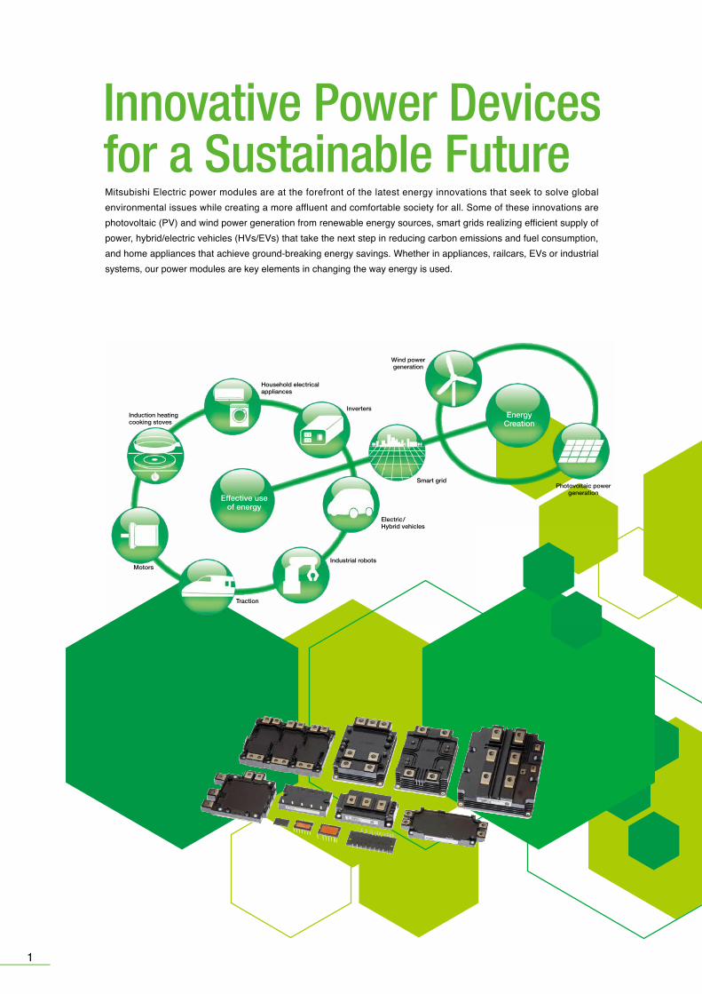
Mitsubishi Electric power modules are at the forefront of the latest energy innovations that seek to solve global environmental issues while creating a more affluent and comfortable society for all. Some of these innovations are photovoltaic (PV) and wind power generation from renewable energy sources, smart grids realizing efficient supply of power, hybrid/electric vehicles (HVs/EVs) that take the next step in reducing carbon emissions and fuel consumption, and home appliances that achieve ground-breaking energy savings. Whether in appliances, railcars, EVs or industrial systems, our power modules are key elements in changing the way energy is used.
Innovative Power Devicesfor a Sustainable Future
Smart gridPhotovoltaic power
generation
Wind powergeneration
Household electricalappliances
Electric/ Hybrid vehicles
MotorsIndustrial robots
Traction
InvertersInduction heatingcooking stoves
Effective useof energy
EnergyCreation
*HV: Hybrid Vehicle *EV: Electric Vehicle *PHEV: Plug-in Hybrid Electric Vehicle
Modules realizing single-control power supply and photocoupler-less systems for household appliances and low-capacity invertersKey Features•Transfer-molded structure incorporating a high thermal conductivity insulation sheet provides heat•High-voltage IC equipped with drive, protection and level-shift circuits for direct control via input signals from a CPU or microcomputer
•Compact board and highly reliable equipment realized through single power-supply and photocoupler-less systems•Includes built-in bootstrap diode (BSD)
Modules with built-in control and protection circuits for AC servo robots and PV power generationKey Features•Built-in protection circuits for short-circuiting, power supply undervoltage and overheating •Highly compatible package with simplified printed circuit board (PCB) design•Special intelligent power modules (IPMs) for power conditioners in PV power generation systems
IGBT modules for general-purpose inverters used in various applicationsKey Features•Various low-inductance packages and power chips available•Compatible with high-frequency, high-voltage (1,700V) applications•Large-capacity modules available for renewable energy systems
High voltage, large capacity and high reliability are realized for traction and power transmission applicationKey Features・Two types of package are realized: "std type" with large output power and "dual type" for
various inverter capacity by easy parallel connection・The abundant field experience more than 20 years especially in the application of bullet train・High reliability due to a long lifetime design and a robust design against severe environment
7th-Generation 1,200V-Class IGBT Chip TechnologyCutting-edge technology realizes energy-saving inverter devices
• Latest thin-wafer processing (n-drift layer) achieves thinner wafer than 6th-generation devices• Performance improved by combining CSTBTTM* and light punch-through (LPT) structures• Inverter system power dissipation mini-mized by its superior performance(lower VCEsat and Eoff)
Focus Technology
*CSTBTTM: Mitsubishi Electric’s unique IGBT that makes use of carrier cumulative effect
Modules realizing high performance and reliability for propulsion inverters in HVs/EVsKey Features•Built-in temperature analog output function realizing highly reliable drive train•High-power/temperature cycle life ensures high reliability•Compliant with the End-of-life Vehicles Directive, regulations relating to substances of environmental concern•High traceability in managing materials/components throughout the entire production process for each product
A small surface mount pakage IPM has been newly developed for fan and low-power motor drive applicationsKey Features・Optimal pin layout realizes easier PCB wiring design and enables smaller PCB size・Newly integrated interlock function in addition to conventional protection features for robust operation・Bootstrap diode is integrated for the P-side drive power supply like conventional DIPIPMTM series,
reducing the number of peripheral external parts
1200V-class IGBT structure
Optimize wafer thicknessImprove performance
6th-gen. IGBT 7th-gen. IGBT
n-drift layer n-drift layer
p+ collector n+ bufferC
E EG
p+ collectorn+ bufferC
E EG
The latest thin wafer process
Comparison of power loss
7th-gen.IGBT
6th-gen. IGBT
5th-gen.IGBT
4th-gen.IGBT
DIPIPMTM
IPMIntelligent Power Modules
IGBT ModulesInsulated Gate Bipolar
Transistor Modules
HVIGBT ModulesHigh-Voltage Insulated Gate Bipolar
Transistor Modules
Power Modules for VehiclesPower Modules for EV/PHEV
MISOPTM
Surface mount package IPM

21
Mitsubishi Electric power modules are at the forefront of the latest energy innovations that seek to solve global environmental issues while creating a more affluent and comfortable society for all. Some of these innovations are photovoltaic (PV) and wind power generation from renewable energy sources, smart grids realizing efficient supply of power, hybrid/electric vehicles (HVs/EVs) that take the next step in reducing carbon emissions and fuel consumption, and home appliances that achieve ground-breaking energy savings. Whether in appliances, railcars, EVs or industrial systems, our power modules are key elements in changing the way energy is used.
Innovative Power Devicesfor a Sustainable Future
Smart gridPhotovoltaic power
generation
Wind powergeneration
Household electricalappliances
Electric/ Hybrid vehicles
MotorsIndustrial robots
Traction
InvertersInduction heatingcooking stoves
Effective useof energy
EnergyCreation
*HV: Hybrid Vehicle *EV: Electric Vehicle *PHEV: Plug-in Hybrid Electric Vehicle
Modules realizing single-control power supply and photocoupler-less systems for household appliances and low-capacity invertersKey Features•Transfer-molded structure incorporating a high thermal conductivity insulation sheet provides heat•High-voltage IC equipped with drive, protection and level-shift circuits for direct control via input signals from a CPU or microcomputer
•Compact board and highly reliable equipment realized through single power-supply and photocoupler-less systems•Includes built-in bootstrap diode (BSD)
Modules with built-in control and protection circuits for AC servo robots and PV power generationKey Features•Built-in protection circuits for short-circuiting, power supply undervoltage and overheating •Highly compatible package with simplified printed circuit board (PCB) design•Special intelligent power modules (IPMs) for power conditioners in PV power generation systems
IGBT modules for general-purpose inverters used in various applicationsKey Features•Various low-inductance packages and power chips available•Compatible with high-frequency, high-voltage (1,700V) applications•Large-capacity modules available for renewable energy systems
High voltage, large capacity and high reliability are realized for traction and power transmission applicationKey Features・Two types of package are realized: "std type" with large output power and "dual type" for
various inverter capacity by easy parallel connection・The abundant field experience more than 20 years especially in the application of bullet train・High reliability due to a long lifetime design and a robust design against severe environment
7th-Generation 1,200V-Class IGBT Chip TechnologyCutting-edge technology realizes energy-saving inverter devices
• Latest thin-wafer processing (n-drift layer) achieves thinner wafer than 6th-generation devices• Performance improved by combining CSTBTTM* and light punch-through (LPT) structures• Inverter system power dissipation mini-mized by its superior performance(lower VCEsat and Eoff)
Focus Technology
*CSTBTTM: Mitsubishi Electric’s unique IGBT that makes use of carrier cumulative effect
Modules realizing high performance and reliability for propulsion inverters in HVs/EVsKey Features•Built-in temperature analog output function realizing highly reliable drive train•High-power/temperature cycle life ensures high reliability•Compliant with the End-of-life Vehicles Directive, regulations relating to substances of environmental concern•High traceability in managing materials/components throughout the entire production process for each product
A small surface mount pakage IPM has been newly developed for fan and low-power motor drive applicationsKey Features・Optimal pin layout realizes easier PCB wiring design and enables smaller PCB size・Newly integrated interlock function in addition to conventional protection features for robust operation・Bootstrap diode is integrated for the P-side drive power supply like conventional DIPIPMTM series,
reducing the number of peripheral external parts
1200V-class IGBT structure
Optimize wafer thicknessImprove performance
6th-gen. IGBT 7th-gen. IGBT
n-drift layer n-drift layer
p+ collector n+ bufferC
E EG
p+ collectorn+ bufferC
E EG
The latest thin wafer process
Comparison of power loss
7th-gen.IGBT
6th-gen. IGBT
5th-gen.IGBT
4th-gen.IGBT
DIPIPMTM
IPMIntelligent Power Modules
IGBT ModulesInsulated Gate Bipolar
Transistor Modules
HVIGBT ModulesHigh-Voltage Insulated Gate Bipolar
Transistor Modules
Power Modules for VehiclesPower Modules for EV/PHEV
MISOPTM
Surface mount package IPM

Surface mount package IPM
43
All-in-one intelligent power modules equipped with 3-phase converter and brake circuit in addition to inverter circuit
Data sheethereFeatured Products
Data sheethere
<Main Features>• Encapsulated with transfer molded resin, integrates three-phase converter,
inverter, brake and control IC• Built-in converter and brake enable system size to be reduced and save design
cost, contributing to total cost reduction• Lower PCB inductance pattern reduces noise, thereby reducing design time
and countermeasure parts required for noise reduction • Built-in BSD*1 with 1,200V withstand voltage reduces number of external parts
and improves reliability
*1 Bootstrap diode*2 Without brake circuit types are also line-up
* For further information, please contact sales office.
PSS05MC1FT, PSS10MC1FT, PSS15MC1FT, PSS25MC1FT, PSS35MC1FT, PSS50MC1F6DIPIPM+TM
P1
RST B
P
NU NV NWN1 N(B)
LVIC
LVIC
Converter Brake Inverter
HVIC
■ Internal circuit diagram
<Main Features>・RC-IGBT*1 incorporated, reducing package size 30% compared to Super-mini DIPIPM・Maximum case temperature increased from 100°C to 115°C, increusing the operating temperature range and leading to easier system design・Additional terminals for floating supply and built-in bootstrap diodes simplify PCB wiring
pattern・Both VOT*2 and OT*3 functions integrated for temperature protection
*1 Reverse conducting IGBT*2 Analog Temperature Output*3 Over Temperature protection
Smaller package size realized by integrating newly designed RC-IGBTRecommended for low-cost inverter and fan controller applications
Featured Products
SLIMDIP-S, SLIMDIP-LSLIMDIPTM
Power supply and control Bootstrap capacitor
Shunt resistor
To motor
NW PUVWNUNV
EVA series, evaluation boards for each DIPIPMTM
Various evaluation boards to easy support system design
Customer Support
SP2SK, SP3SKSurface mount package IPM MISOPTM
<Main Features>・Optimal pin layout realizes easier PCB wiring design and enables smaller PCB size・Insulation distance between pins ensured, realizing easier board mounting without coating process・Newly integrated interlock function in addition to conventional protection features for robust operation・Installing RC-IGBT*1 simultaneously realizes compact package and low loss performance can go thogether・Bootstrap diode is integrated for the P-side drive power supply like conventional DIPIPMTM series, reducing
the number of peripheral external parts
A small Surface mount package IPM has been newly developed for fan and low-power motor drive applications
Data sheethereNew Products
■ Schematic drawing ■ Outline Drawing
2A
3A600V
SP2SK★★
SP3SK★★
Surface mountpackage
Type name Rated current Rated voltage Chips Protection Shape
★★:Under development
RC-IGBT, HVIC,LVIC, BSD
UV, SC, OTVOT, IL
■MISOPTM
*1 Reverse-conducting IGBT
UV: Power supply Under Voltage protectionSC: Short Circuit protectionOT: Over Temperature protectionVOT:Analog Temperature OutputIL:Inter Lock
[Term]
0.76.3
7.019.9
3-4.32-2.6 0.8
0.5
27.4
11-1.00.8 15.0
5.01.4
15.2
19.3
0.84(3.45)
3.3
Low Side Driver
BSD
Input Logic
Protection circuit
Op. AMP
Ref
UV
SC
Temperature sensor
OT
RC-IGBT
Input Logic (UV detection)
High Side Level Shift Driver (UV detection)
Interlock
Unit:mm
UP(8)
VW
FB (7)
VW
FS (6)
VV
FB (5)
VV
FS (4)
VU
FB (3)
VU
FS (2)
VP(9)
WP(10)
VP1(11)
VNC(12)
UN(13)
VN(14)
WN(15)
P(27)
U(26)V(25)
W(24)
NU(23)
NV(22)
NW(21)
VN1(16)
CIN(18)
VOT(19)
FO(17)
Super mini DIPIPMTM evaluation board
EVA11-SDIP DIPIPM+TM evaluation boardEVA14-DIP+
SLIMDIPTM evaluation boardEVA15-SLIM
DIPIPM+TM evaluation
boardEVA03-DIP+
SLIMDIPTM evaluation boardEVA01-SLIM
DIPIPMTM
27
1
21
19
Spe
cific
atio
nsP
rote
ctiv
eF
unct
ion
65
■ Series Matrix of 1200V DIPIPMTM
1200V
Ver.4 CIB/CI Ver.6
LargeMini
DIPIPM+
5
10
15
25
35
50
IGBT/MOSFETUVSCOTVOT
Active inputEmitter pin of N-sideFault outputInsulation voltageInsulation structureRoHS directive
CSTBTP-side/N-side
N-sideー
N-sideHigh(5V)
OpenN-side (UV,SC)
2500VrmsInsulation sheet
Compliant
CSTBTP-side/N-side
N-sideー
N-sideHigh(5V)
OpenN-side (UV,SC)
2500VrmsInsulation sheet
Compliant
CSTBTP-side/N-side
N-sideー
N-sideHigh(5V)
OpenN-side (UV,SC)
2500VrmsInsulation sheet
Compliant
Pin type ー ー ー
CSTBTP-side/N-side/Brake
N-sideー
N-sideHigh(5V)
OpenN-side (UV,SC)
2500VrmsInsulation sheet
Compliant
ー
IC(A)Series
VCES(V)
PSS05S72FT
PSS10S72FT
PSS05SA2FT
PSS10SA2FT
PSS15SA2FT
PSS25SA2FT
PSS35SA2FT
PSS50SA2FT
PS22A72
PS22A73
PS22A74
PS22A76
PS22A78-E
PS22A79
PSS05MC1FTPSS05NC1FT*1
PSS10MC1FTPSS10NC1FT*1
PSS15MC1FTPSS15NC1FT*1
PSS25MC1FTPSS25NC1FT*1
PSS35MC1FTPSS35NC1FT*1
■ Type Name Definition of DIPIPMTM
Chip typeDIPIPM
OptionsVoltage class
Rated current
Circuit construction
FunctionSeriesPackage
PS
BSD: Bootstrap DiodeCSTBTTM: Mitsubishi Electric’s unique IGBT that makes use of the carrier cumulative effectHVIC: High Voltage ICLVIC: Low Voltage ICUV: Power supply Under Voltage protectionOT: Over Temperature protectionSC: Short Circuit protectionVOT: Analog Temperature OutputRoHS: Restriction of hazardous substances in electrical and electronic equipmentCIB: Converter Inverter BrakeCI: Converter Inverter
[Term]
[Notes] *1: PSS**NC1FT is not included brake
Not recommended : Please contact to the sales offices.
Chip
Spec
ifica
tions
Pro
tect
ive
Func
tion
Line-up of DIPIPMTM
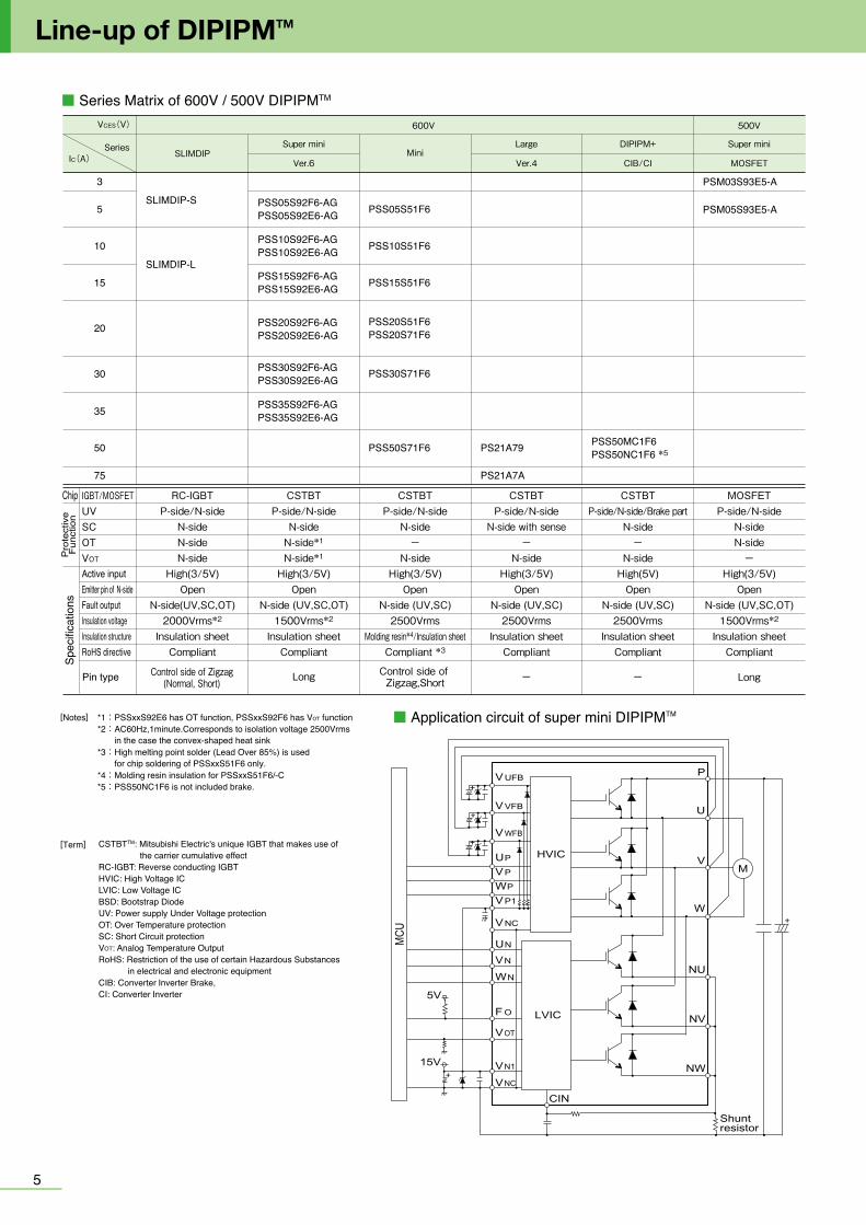
■ Series Matrix of 600V / 500V DIPIPMTM
600V 500V
Super mini
MOSFETVer.6
Super miniSLIMDIP
IGBT/MOSFETUVSCOTVOT
Active inputEmitter pin of N-sideFault outputInsulation voltageInsulation structureRoHS directive
35
50
75
IC(A)Series
VCES(V)
20
5
3
10
15
30
Pin type
■ Application circuit of super mini DIPIPMTM
CSTBTP-side/N-side
N-sideN-side*1
N-side*1
High(3/5V)Open
N-side (UV,SC,OT)1500Vrms*2
Insulation sheetCompliant
Long
RC-IGBTP-side/N-side
N-sideN-sideN-side
High(3/5V)Open
N-side(UV,SC,OT)2000Vrms*2
Insulation sheetCompliant
Control side of Zigzag(Normal, Short)
PSS05S92F6-AGPSS05S92E6-AG
PSS10S92F6-AGPSS10S92E6-AG
PSS15S92F6-AGPSS15S92E6-AG
PSS20S92F6-AGPSS20S92E6-AG
PSS30S92F6-AGPSS30S92E6-AG
PSS35S92F6-AGPSS35S92E6-AG
Mini
Control side of Zigzag,Short
CSTBTP-side/N-side
N-sideー
N-sideHigh(3/5V)
OpenN-side (UV,SC)
2500VrmsMolding resin*4/Insulation sheet
Compliant *3
PSS05S51F6
PSS10S51F6
PSS15S51F6
PSS20S51F6PSS20S71F6
PSS30S71F6
PSS50S71F6
Large
Ver.4
ー
CSTBTP-side/N-side
N-side with senseー
N-sideHigh(3/5V)
OpenN-side (UV,SC)
2500VrmsInsulation sheet
Compliant
PS21A79
PS21A7A
CIB/CI
DIPIPM+
ー
CSTBTP-side/N-side/Brake part
N-sideー
N-sideHigh(5V)
OpenN-side (UV,SC)
2500VrmsInsulation sheet
Compliant
PSS50MC1F6PSS50NC1F6 *5
Long
MOSFETP-side/N-side
N-sideN-side
ーHigh(3/5V)
OpenN-side (UV,SC,OT)
1500Vrms*2
Insulation sheetCompliant
PSM03S93E5-A
PSM05S93E5-A
[Notes] *1:PSSxxS92E6 has OT function, PSSxxS92F6 has VOT function*2:AC60Hz,1minute.Corresponds to isolation voltage 2500Vrms in the case the convex-shaped heat sink*3:High melting point solder (Lead Over 85%) is used for chip soldering of PSSxxS51F6 only.*4:Molding resin insulation for PSSxxS51F6/-C*5:PSS50NC1F6 is not included brake.
CSTBTTM: Mitsubishi Electric's unique IGBT that makes use of the carrier cumulative effectRC-IGBT: Reverse conducting IGBT HVIC: High Voltage ICLVIC: Low Voltage ICBSD: Bootstrap DiodeUV: Power supply Under Voltage protection OT: Over Temperature protectionSC: Short Circuit protectionVOT: Analog Temperature OutputRoHS: Restriction of the use of certain Hazardous Substances in electrical and electronic equipmentCIB: Converter Inverter Brake, CI: Converter Inverter
[Term]
SLIMDIP-S
75 PSS75SA2FT
Chip
+
+
MC
U
M
Shuntresistor
5V
VUFB
VVFB
V WFB
UN
VN
WN
F O
VN1
VNC
P
U
W
LVIC
V VP
WP
UP
VP1
CIN
+
VNC
NW
NU
NV VOT
+
+
15V
HVIC
SLIMDIP-L

Spe
cific
atio
nsP
rote
ctiv
eF
unct
ion
65
■ Series Matrix of 1200V DIPIPMTM
1200V
Ver.4 CIB/CI Ver.6
LargeMini
DIPIPM+
5
10
15
25
35
50
IGBT/MOSFETUVSCOTVOT
Active inputEmitter pin of N-sideFault outputInsulation voltageInsulation structureRoHS directive
CSTBTP-side/N-side
N-sideー
N-sideHigh(5V)
OpenN-side (UV,SC)
2500VrmsInsulation sheet
Compliant
CSTBTP-side/N-side
N-sideー
N-sideHigh(5V)
OpenN-side (UV,SC)
2500VrmsInsulation sheet
Compliant
CSTBTP-side/N-side
N-sideー
N-sideHigh(5V)
OpenN-side (UV,SC)
2500VrmsInsulation sheet
Compliant
Pin type ー ー ー
CSTBTP-side/N-side/Brake
N-sideー
N-sideHigh(5V)
OpenN-side (UV,SC)
2500VrmsInsulation sheet
Compliant
ー
IC(A)Series
VCES(V)
PSS05S72FT
PSS10S72FT
PSS05SA2FT
PSS10SA2FT
PSS15SA2FT
PSS25SA2FT
PSS35SA2FT
PSS50SA2FT
PS22A72
PS22A73
PS22A74
PS22A76
PS22A78-E
PS22A79
PSS05MC1FTPSS05NC1FT*1
PSS10MC1FTPSS10NC1FT*1
PSS15MC1FTPSS15NC1FT*1
PSS25MC1FTPSS25NC1FT*1
PSS35MC1FTPSS35NC1FT*1
■ Type Name Definition of DIPIPMTM
Chip typeDIPIPM
OptionsVoltage class
Rated current
Circuit construction
FunctionSeriesPackage
PS
BSD: Bootstrap DiodeCSTBTTM: Mitsubishi Electric’s unique IGBT that makes use of the carrier cumulative effectHVIC: High Voltage ICLVIC: Low Voltage ICUV: Power supply Under Voltage protectionOT: Over Temperature protectionSC: Short Circuit protectionVOT: Analog Temperature OutputRoHS: Restriction of hazardous substances in electrical and electronic equipmentCIB: Converter Inverter BrakeCI: Converter Inverter
[Term]
[Notes] *1: PSS**NC1FT is not included brake
Not recommended : Please contact to the sales offices.
Chip
Spec
ifica
tions
Pro
tect
ive
Func
tion
Line-up of DIPIPMTM
■ Series Matrix of 600V / 500V DIPIPMTM
600V 500V
Super mini
MOSFETVer.6
Super miniSLIMDIP
IGBT/MOSFETUVSCOTVOT
Active inputEmitter pin of N-sideFault outputInsulation voltageInsulation structureRoHS directive
35
50
75
IC(A)Series
VCES(V)
20
5
3
10
15
30
Pin type
■ Application circuit of super mini DIPIPMTM
CSTBTP-side/N-side
N-sideN-side*1
N-side*1
High(3/5V)Open
N-side (UV,SC,OT)1500Vrms*2
Insulation sheetCompliant
Long
RC-IGBTP-side/N-side
N-sideN-sideN-side
High(3/5V)Open
N-side(UV,SC,OT)2000Vrms*2
Insulation sheetCompliant
Control side of Zigzag(Normal, Short)
PSS05S92F6-AGPSS05S92E6-AG
PSS10S92F6-AGPSS10S92E6-AG
PSS15S92F6-AGPSS15S92E6-AG
PSS20S92F6-AGPSS20S92E6-AG
PSS30S92F6-AGPSS30S92E6-AG
PSS35S92F6-AGPSS35S92E6-AG
Mini
Control side of Zigzag,Short
CSTBTP-side/N-side
N-sideー
N-sideHigh(3/5V)
OpenN-side (UV,SC)
2500VrmsMolding resin*4/Insulation sheet
Compliant *3
PSS05S51F6
PSS10S51F6
PSS15S51F6
PSS20S51F6PSS20S71F6
PSS30S71F6
PSS50S71F6
Large
Ver.4
ー
CSTBTP-side/N-side
N-side with senseー
N-sideHigh(3/5V)
OpenN-side (UV,SC)
2500VrmsInsulation sheet
Compliant
PS21A79
PS21A7A
CIB/CI
DIPIPM+
ー
CSTBTP-side/N-side/Brake part
N-sideー
N-sideHigh(5V)
OpenN-side (UV,SC)
2500VrmsInsulation sheet
Compliant
PSS50MC1F6PSS50NC1F6 *5
Long
MOSFETP-side/N-side
N-sideN-side
ーHigh(3/5V)
OpenN-side (UV,SC,OT)
1500Vrms*2
Insulation sheetCompliant
PSM03S93E5-A
PSM05S93E5-A
[Notes] *1:PSSxxS92E6 has OT function, PSSxxS92F6 has VOT function*2:AC60Hz,1minute.Corresponds to isolation voltage 2500Vrms in the case the convex-shaped heat sink*3:High melting point solder (Lead Over 85%) is used for chip soldering of PSSxxS51F6 only.*4:Molding resin insulation for PSSxxS51F6/-C*5:PSS50NC1F6 is not included brake.
CSTBTTM: Mitsubishi Electric's unique IGBT that makes use of the carrier cumulative effectRC-IGBT: Reverse conducting IGBT HVIC: High Voltage ICLVIC: Low Voltage ICBSD: Bootstrap DiodeUV: Power supply Under Voltage protection OT: Over Temperature protectionSC: Short Circuit protectionVOT: Analog Temperature OutputRoHS: Restriction of the use of certain Hazardous Substances in electrical and electronic equipmentCIB: Converter Inverter Brake, CI: Converter Inverter
[Term]
SLIMDIP-S
75 PSS75SA2FT
Chip
+
+
MC
U
M
Shuntresistor
5V
V UFB
VVFB
V WFB
UN
VN
WN
F O
VN1
VNC
P
U
W
LVIC
V VP
WP
UP
VP1
CIN
+
VNC
NW
NU
NV VOT
+
+
15V
HVIC
SLIMDIP-L

P N U V W
P NC U V W
87
IPM
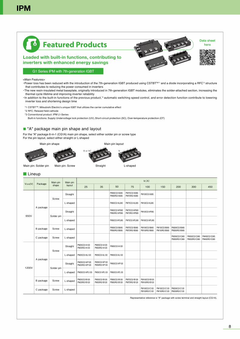
For the "A" package 6-in-1 (CG1A) main pin shape, select either solder pin or screw typeFor the pin layout, select either straight or L-shaped
*1 CSTBT™: Mitsubishi Electric’s unique IGBT that utilizes the carrier cumulative effect*2 RFC: Relaxed field cathode*3 Conventional product: IPM L1-Series Built-in functions: Supply Undervoltage lock protection (UV)、Short-circuit protection (SC), Over-temperature protection (OT)
Loaded with built-in functions, contributing to inverters with enhanced energy savings
Featured ProductsData sheet
here
G1 Series IPM with 7th-generation IGBT
■ "A" package main pin shape and layout
<Main Features>・Power loss has been reduced with the introduction of the 7th-generation IGBT produced using CSTBTTM*1 and a diode incorporating a RFC*2 structure
that contributes to reducing the power consumed in inverters・The new resin-insulated metal baseplate, originally introduced in 7th-generation IGBT modules, eliminates the solder-attached section, increasing the
thermal cycle lifetime and improving inverter reliability・In addition to the built-in functions of the previous product,*3 automatic switching speed control, and error detection function contribute to lowering
inverter loss and shortening design time
Main pin layoutMain pin shape
Main pin: Solder pin Main pin: Screw L-shaped Straight
B or NC N
Representative reference is "A" package with screw terminal and straight layout (CG1A).
■ Lineup
VCES(V) PackageIc(A)
650V
1200V
A package
B package
C package
A package
B package
C package
Main pinshape
Main pinlayout
Straight
L-shaped
Straight
L-shaped
L-shaped
L-shaped
Straight
L-shaped
Straight
L-shaped
L-shaped
L-shaped
Screw
Screw
Screw
Screw
Screw
Screw
Solder pin
Solder pin
Mini DIPIPM (PSSxxS51F6)
Large DIPIPM
(2.54×10)
1.8
8.6
0.8 22.7
168
10±0.3 10±0.3 10±0.3 10±0.3 10±0.3 10±0.3
70 ±0.379 ±0.5
2.54±0.3
31±0
.5
A = 2.54±0.3B = 5.08±0.3
B B B
12 53 4 6 87 9 1110 15 1716 20
303132
333440
294241
18 191412 13
B
B
B
A A A AA A
A 2.8
12.7
Type name , Lot No. 2-ø4.5±0.2
28 27 26 25 24 23 22 21 20 19 18 16 15 13 12 10 9 8 7 6 5 4 3 2 11417 11
3536
2930
37 34 33 32 31
Type name , Lot No.
6.7±0.32.54±0.3
(6.3
)(2
)
(2)(0.5)
46.228(26×1.778)
2.54±0.3
7.62±0.37.62±0.37.62±0.35.76±0.3
1.778±0.2
30.5
15.2
50.
50.
5
(41)
4942±0.15
10.5
6.5±
0.5
2-Ø3.3
28 27 26 25 24 23 22 21 20 19 18 16 15 13 12 10 9 8 7 6 5 4 3 2 11417 11
3536
2930
37 34 33 32 31
Type name , Lot No.
6.7±0.3
(6.3
)(2
)
1.778±0.2
46.228(26×1.778)
2.54±0.32.54±0.3
7.62±0.37.62±0.37.62±0.3
5.76±0.3
10.5
30.5
0.5
0.5
15.2
5
42±0.15
6.5±
0.5
(2)(0.5)
49
(41)
2-Ø3.3
Mini DIPIPM(PSSxxS51F6)Zigzag
■ Outline Drawing of DIPIPMTM
Super mini DIPIPM Ver.6MOSFET Super mini DIPIPMLong
Unit :mm
1.78±0.2
3.3±0.3 3.3±0.3
6.6±0.3 7.62±0.3 7.62±0.3 7.62±0.3 7.62±0.3
1.78±0.21.78±0.2
(11×1.78)
31
15.5
46±0.2 3.25
0.51.51
2
52.5
7.112
.7
28
2930
31 38
1
Type name, Lot No.
4.32±0.2 4.32±0.2
2-ø3.3
0.61
1
2.04±0.3
3.95±0.3
18 25
17 1
Type nameLot No.12
0.28
0.28
8-0.6
14×2.54(=35.56)
3 MIN2-R1.6
4-C1.2
24±0
.5(1
)1.778±0.2
35±0.3
20×1.778(=35.56)38±0.5
16-0.5
2.54±0.2
14±0
.5
5.5±0
.5
HEAT SINK SIDE
0.5 0.50.5 0.5
Mini DIPIPM (PSSxxS71F6)1200V Mini DIPIPM
DIPIPM+
A AAA
1 2
0.5
5.7
1.2 0.6
6.45
13
0.5
36 35 34 33 32 31 30 29 28 27 26
3 4 5 6 7 910 1314151617181920212223 25248
BB
B BA
A=1.778 0.3±
1.778 0.3±1.778 12x
B=3.556 0.3±6.58 0.3±
14.6
50.
3±
340.
5±
8.7 0.3±
8.7 0.3± 8 0.3± 8 0.3± 8 0.3± 8 0.3±
76 0.3±
85 0.5±
8 0.3± 8 0.3± 8 0.3± 8 0.3± 3 0.3±
3 0.3±
8.7 0.3± 8.7 0.3±
SLIMDIPNormal
32.8±0.5
29.8±0.3
5±0.2
5.5±
0.5
9.4±
0.3
15-1.15±0.15
19-0.4
20
0.64-C1.2
21
2-R1.6
0.5
0.45
6×5 ( =30 )
0.3
0.5
0.45
10.8
18.8
(0.1
)
1
1.025
7-0.6
HEAT SINK SIDE
32.8±0.5
29.8±0.3
5±0.2
5.5±
0.5
9.4±
0.3
15-1.15±0.15
19-0.4
20
0.64-C1.2
21
2-R1.6
0.5
0.45
6×5 ( =30 )
S
0.3
0.5
0.45
9.3
18.8
(0.1
)
1
1.025
7-0.6
HEAT SINK SIDE
Line-up of DIPIPMTM
SLIMDIPShort
25 35 50 75 100 150 200 300 450
PM25CG1A120PM25RG1A120
PM25CG1AL120
PM25CG1AP120PM25RG1AP120
PM25CG1APL120
PM25CG1B120PM25RG1B120
PM75CG1A065PM75RG1A065
PM75CG1AP065PM75RG1AP065
PM75CG1APL065
PM75CG1B065PM75RG1B065
PM75CG1B120PM75RG1B120
PM75CG1AL065
PM50CG1A065PM50RG1A065
PM50CG1AP065PM50RG1AP065
PM50CG1APL065
PM50CG1B065PM50RG1B065
PM50CG1AL065
PM35CG1A120PM35RG1A120
PM35CG1AL120
PM35CG1AP120PM35RG1AP120
PM35CG1APL120
PM35CG1B120PM35RG1B120
PM50CG1A120
PM50CG1AL120
PM50CG1AP120
PM50CG1APL120
PM50CG1B120PM50RG1B120
PM100CG1A065
PM100CG1AL065
PM100CG1AP065
PM100CG1APL065
PM100CG1B065PM100RG1B065
PM150CG1B065PM150RG1B065
PM200CG1B065PM200RG1B065
PM200CG1C065PM200RG1C065
PM300CG1C065PM300RG1C065
PM450CG1C065PM450RG1C065
PM200CG1C120PM200RG1C120
PM150CG1C120PM150RG1C120
PM100CG1B120PM100RG1B120
PM100CG1C120PM100RG1C120
P N U V W
P NC U V W
87
IPM
For the "A" package 6-in-1 (CG1A) main pin shape, select either solder pin or screw typeFor the pin layout, select either straight or L-shaped
*1 CSTBT™: Mitsubishi Electric’s unique IGBT that utilizes the carrier cumulative effect*2 RFC: Relaxed field cathode*3 Conventional product: IPM L1-Series Built-in functions: Supply Undervoltage lock protection (UV)、Short-circuit protection (SC), Over-temperature protection (OT)
Loaded with built-in functions, contributing to inverters with enhanced energy savings
Featured ProductsData sheet
here
G1 Series IPM with 7th-generation IGBT
■ "A" package main pin shape and layout
<Main Features>・Power loss has been reduced with the introduction of the 7th-generation IGBT produced using CSTBTTM*1 and a diode incorporating a RFC*2 structure
that contributes to reducing the power consumed in inverters・The new resin-insulated metal baseplate, originally introduced in 7th-generation IGBT modules, eliminates the solder-attached section, increasing the
thermal cycle lifetime and improving inverter reliability・In addition to the built-in functions of the previous product,*3 automatic switching speed control, and error detection function contribute to lowering
inverter loss and shortening design time
Main pin layoutMain pin shape
Main pin: Solder pin Main pin: Screw L-shaped Straight
B or NC N
Representative reference is "A" package with screw terminal and straight layout (CG1A).
■ Lineup
VCES(V) PackageIc(A)
650V
1200V
A package
B package
C package
A package
B package
C package
Main pinshape
Main pinlayout
Straight
L-shaped
Straight
L-shaped
L-shaped
L-shaped
Straight
L-shaped
Straight
L-shaped
L-shaped
L-shaped
Screw
Screw
Screw
Screw
Screw
Screw
Solder pin
Solder pin
Mini DIPIPM (PSSxxS51F6)
Large DIPIPM
(2.54×10)
1.8
8.6
0.8 22.7
168
10±0.3 10±0.3 10±0.3 10±0.3 10±0.3 10±0.3
70 ±0.379 ±0.5
2.54±0.3
31±0
.5
A = 2.54±0.3B = 5.08±0.3
B B B
12 53 4 6 87 9 1110 15 1716 20
303132
333440
294241
18 191412 13
B
B
B
A A A AA A
A 2.8
12.7
Type name , Lot No. 2-ø4.5±0.2
28 27 26 25 24 23 22 21 20 19 18 16 15 13 12 10 9 8 7 6 5 4 3 2 11417 11
3536
2930
37 34 33 32 31
Type name , Lot No.
6.7±0.32.54±0.3
(6.3
)(2
)
(2)(0.5)
46.228(26×1.778)
2.54±0.3
7.62±0.37.62±0.37.62±0.35.76±0.3
1.778±0.2
30.5
15.2
50.
50.
5
(41)
4942±0.15
10.5
6.5±
0.5
2-Ø3.3
28 27 26 25 24 23 22 21 20 19 18 16 15 13 12 10 9 8 7 6 5 4 3 2 11417 11
3536
2930
37 34 33 32 31
Type name , Lot No.
6.7±0.3
(6.3
)(2
)
1.778±0.2
46.228(26×1.778)
2.54±0.32.54±0.3
7.62±0.37.62±0.37.62±0.3
5.76±0.3
10.5
30.5
0.5
0.5
15.2
5
42±0.15
6.5±
0.5
(2)(0.5)
49
(41)
2-Ø3.3
Mini DIPIPM(PSSxxS51F6)Zigzag
■ Outline Drawing of DIPIPMTM
Super mini DIPIPM Ver.6MOSFET Super mini DIPIPMLong
Unit :mm
1.78±0.2
3.3±0.3 3.3±0.3
6.6±0.3 7.62±0.3 7.62±0.3 7.62±0.3 7.62±0.3
1.78±0.21.78±0.2
(11×1.78)
31
15.5
46±0.2 3.25
0.51.51
2
52.5
7.112
.7
28
2930
31 38
1
Type name, Lot No.
4.32±0.2 4.32±0.2
2-ø3.3
0.61
1
2.04±0.3
3.95±0.3
18 25
17 1
Type nameLot No.12
0.28
0.28
8-0.6
14×2.54(=35.56)
3 MIN2-R1.6
4-C1.2
24±0
.5(1
)
1.778±0.2
35±0.3
20×1.778(=35.56)38±0.5
16-0.5
2.54±0.2
14±0
.5
5.5±0
.5
HEAT SINK SIDE
0.5 0.50.5 0.5
Mini DIPIPM (PSSxxS71F6)1200V Mini DIPIPM
DIPIPM+
A AAA
1 2
0.5
5.7
1.2 0.6
6.45
13
0.5
36 35 34 33 32 31 30 29 28 27 26
3 4 5 6 7 910 1314151617181920212223 25248
BB
B BA
A=1.778 0.3±
1.778 0.3±1.778 12x
B=3.556 0.3±6.58 0.3±
14.6
50.
3±
340.
5±
8.7 0.3±
8.7 0.3± 8 0.3± 8 0.3± 8 0.3± 8 0.3±
76 0.3±
85 0.5±
8 0.3± 8 0.3± 8 0.3± 8 0.3± 3 0.3±
3 0.3±
8.7 0.3± 8.7 0.3±
SLIMDIPNormal
32.8±0.5
29.8±0.3
5±0.2
5.5±
0.5
9.4±
0.3
15-1.15±0.15
19-0.4
20
0.64-C1.2
21
2-R1.6
0.5
0.45
6×5 ( =30 )
0.3
0.5
0.45
10.8
18.8
(0.1
)
1
1.025
7-0.6
HEAT SINK SIDE
32.8±0.5
29.8±0.3
5±0.2
5.5±
0.5
9.4±
0.3
15-1.15±0.15
19-0.4
20
0.64-C1.2
21
2-R1.6
0.5
0.45
6×5 ( =30 )
S
0.3
0.5
0.45
9.3
18.8
(0.1
)
1
1.025
7-0.6
HEAT SINK SIDE
Line-up of DIPIPMTM
SLIMDIPShort
25 35 50 75 100 150 200 300 450
PM25CG1A120PM25RG1A120
PM25CG1AL120
PM25CG1AP120PM25RG1AP120
PM25CG1APL120
PM25CG1B120PM25RG1B120
PM75CG1A065PM75RG1A065
PM75CG1AP065PM75RG1AP065
PM75CG1APL065
PM75CG1B065PM75RG1B065
PM75CG1B120PM75RG1B120
PM75CG1AL065
PM50CG1A065PM50RG1A065
PM50CG1AP065PM50RG1AP065
PM50CG1APL065
PM50CG1B065PM50RG1B065
PM50CG1AL065
PM35CG1A120PM35RG1A120
PM35CG1AL120
PM35CG1AP120PM35RG1AP120
PM35CG1APL120
PM35CG1B120PM35RG1B120
PM50CG1A120
PM50CG1AL120
PM50CG1AP120
PM50CG1APL120
PM50CG1B120PM50RG1B120
PM100CG1A065
PM100CG1AL065
PM100CG1AP065
PM100CG1APL065
PM100CG1B065PM100RG1B065
PM150CG1B065PM150RG1B065
PM200CG1B065PM200RG1B065
PM200CG1C065PM200RG1C065
PM300CG1C065PM300RG1C065
PM450CG1C065PM450RG1C065
PM200CG1C120PM200RG1C120
PM150CG1C120PM150RG1C120
PM100CG1B120PM100RG1B120
PM100CG1C120PM100RG1C120

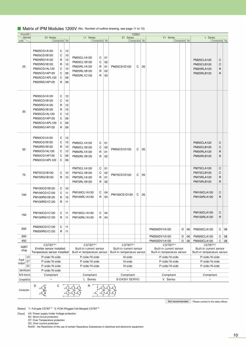
■ Matrix of IPM Modules 1200V (No.: Number of outline drawing, see page 11 to 12)
9
Line-up of IPM
UVOTSC
D C R
IGBTchip
RoHS directiveCompatibility
Connection
1200V
CSTBT*1 Built-in current sensor
Built-in temperature sensor
P-side/N-sideP-side/N-sideP-side/N-side
-CompliantL Series
L1 Series
CSTBT*1
Emitter sensor installedTemperature sensor installed
P-side/N-sideP-side/N-sideP-side/N-sideP-side/N-side
Compliant-
G1 Series
CSTBT*1 Built-in current sensor
Built-in temperature sensor
N-sideN-sideN-side
-Compliant
S-DASH SERVO
S1 Series
CSTBT*1 Built-in current sensor
Built-in temperature sensor
P-side/N-sideP-side/N-sideP-side/N-side
-CompliantV Series
V1 Series
CSTBT*2 Built-in current sensor
Built-in temperature sensor
P-side/N-sideP-side/N-sideP-side/N-side
-Compliant
-
L SeriesSeriesIC(A)
VCES(V)
Not recommended : Please contact to the sales offices.
[Notes]
[Term] UV: Power supply Under Voltage protectionSC: Short Circuit protectionOT: Over Temperature protectionOC: Over current protectionRoHS:the Restriction of the use of certain Hazardous Substances in electrical and electronic equipment
*1: Full-gate CSTBTTM *2: PCM (Plugged Cell Merged) CSTBTTM
No.Connection No.Connection No.Connection No.Connection No.Connection
Faultoutput
Identification
■ Matrix of IPM Modules 650V/600V (No.: Number of outline drawing, see page 11 to 12)
UVOTSC
400/450
600800
300
200
150
100
75
50
D B4 B5 B6 C R
600V650V
P-side/N-sideP-side/N-sideP-side/N-side
-Compliant
-
CSTBT*2 Built-in emitter sensor
Built-in temperature sensor
PM150CLA060PM150RLA060
PM600CLA060
PM100CLA060PM100RLA060
CR
PM75CLA060PM75CLB060PM75RLA060PM75RLB060
CCRR
PM50CLA060PM50CLB060PM50RLA060PM50RLB060
CCRR
CR
PM200CLA060PM200RLA060
CR
PM450CLA060 C 08
C 08
L Series
CSTBT*1 Built-in emitter sensor
Built-in temperature sensorP-side/N-sideP-side/N-sideP-side/N-side
-CompliantL Series
CSTBT*1
Emitter sensor installedTemperature sensor installed
P-side/N-sideP-side/N-sideP-side/N-sideP-side/N-side
Compliant-
PM150CL1A060PM150CL1B060PM150RL1A060PM150RL1B060
CCRR
PM75CL1A060PM75CL1B060PM75RL1A060PM75RL1B060
CCRR
01020102
01020102
PM100CL1A060PM100CL1B060PM100RL1A060PM100RL1B060
CCRR
01020102
CR
0404
PM200CL1A060PM200RL1A060
CCRRR
PM50CL1A060PM50CL1B060PM50RL1A060PM50RL1B060PM50RL1C060
0102010203
L1 SeriesNo.
G1 Series
N-sideN-sideN-side
-Compliant
S-DASH SERVO
CSTBT*1 Built-in emitter sensor
Built-in temperature sensor
C
CPM50CS1D060 05
CPM100CS1D060 05
05PM150CS1D060
C 05PM200CS1D060
S1 Series
P-side/N-sideP-side/N-sideP-side/N-side
-CompliantV Series
CSTBT*1 Built-in emitter sensor
Built-in temperature sensor
DD
PM400DV1A060 D 06
0607
V1 Series
P-side/N-sideP-side/N-sideP-side/N-side
-Compliant
-
CSTBT*1 Built-in emitter sensor
Built-in temperature sensor
PM50B4LA060PM50B5LA060PM50B6LA060PM50B4LB060PM50B5LB060PM50B6LB060PM50B4L1C060PM50B5L1C060PM50B6L1C060
B4B5B6B4B5B6B4B5B6
010101020202030303
PhotovoltaicIC(A)
RoHS directiveCompatibility
Connection
SeriesVCES(V)
UV: Power supply Under Voltage protectionSC: Short Circuit protectionOT: Over Temperature protectionOC: Over current protectionRoHS: Restriction of hazardous substances in electrical and electronic equipment
[Notes]
[Term]
*1: Full-gate CSTBTTM *2: PCM (Plugged Cell Merged) CSTBTTM
Not recommended : Please contact to the sales offices.
Connection No.Connection No.Connection No.Connection No.Connection No.Connection
IGBTchip
Faultoutput
PM75B4LA060PM75B5LA060PM75B6LA060PM75B4LB060PM75B5LB060PM75B6LB060PM75B4L1C060PM75B5L1C060PM75B6L1C060
B4B5B6B4B5B6B4B5B6
010101020202030303
PM75CS1D060 C 05
PM600DV1A060PM800DV1B060
CR
0404
PM300CL1A060PM300RL1A060
CR
PM300CLA060PM300RLA060
Identification
PM75CG1A065PM75RG1A065PM75CG1B065PM75RG1B065PM75CG1AL065PM75CG1AP065PM75CG1APL065PM75RG1AP065
CRCRCCCR
1212101012090909
PM50CG1A065PM50RG1A065PM50CG1B065PM50RG1B065PM50CG1AL065PM50CG1AP065PM50CG1APL065PM50RG1AP065
CRCRCCCR
1212101012090909
PM150CG1B065PM150RG1B065
CR
1010
PM300CG1C065PM300RG1C065
CR
1111
PM450CG1C065PM450RG1C065
CR
1111
PM100CG1A065PM100CG1B065PM100RG1B065PM100CG1AL065PM100CG1AP065PM100CG1APL065
CCRCCC
121010120909
CRCR
10101111
PM200CG1B065PM200RG1B065PM200CG1C065PM200RG1C065
200
300450
150
100
75
50
25
PM25CL1A120PM25CL1B120PM25RL1A120PM25RL1B120PM25RL1C120
CCRRR
0102010203
PM25CG1A120PM25CG1B120PM25RG1A120PM25RG1B120PM25CG1AL120PM25CG1AP120PM25CG1APL120PM25RG1AP120
CCRRCCCR
1210121012090909
PM50CG1A120PM50CG1B120PM50RG1B120PM50CG1AL120PM50CG1AP120PM50CG1APL120
CCRCCC
121010120909
35
PM35CG1A120PM35CG1B120PM35RG1A120PM35RG1B120PM35CG1AL120PM35CG1AP120PM35CG1APL120PM35RG1AP120
CCRRCCCR
1210121012090909
PM100CG1B120PM100CG1C120PM100RG1B120PM100RG1C120
CCRR
10111011
PM75CG1B120PM75RG1B120
CR
1010
PM150CG1C120PM150RG1C120
CR
1111
PM200CG1C120PM200RG1C120
CR
1111
PM75CS1D120 C
PM25CS1D120 C 05
PM50CS1D120 C 05
CPM100CS1D120 05
05
PM200DV1A120
PM300DV1A120PM450DV1A120
D
DD
06
0606
PM50CLA120PM50CLB120PM50RLA120PM50RLB120
CCRR
CCRR
PM25CLA120PM25CLB120PM25RLA120PM25RLB120
08
0808
PM75CL1A120PM75CL1B120PM75RL1A120PM75RL1B120
CCRR
PM50CL1A120PM50CL1B120PM50RL1A120PM50RL1B120
CCRR
01020102
01020102
PM200CLA120
PM300CLA120PM450CLA120
C
CC
PM75CLA120PM75CLB120PM75RLA120PM75RLB120
CCRR
PM150CLA120PM150RLA120
CR
PM100CLA120PM100RLA120
CR
PM150CL1A120PM150RL1A120
CR
0404
PM100CL1A120PM100RL1A120
CR
0404
10

1110
1211
Line-up of IPM
■ Outline Drawing of IPM
PM200,300,450CG1C/RG1C065PM100,150,200CG1C/RG1C120
12Unit:mm
120106766.518.75
163-2
21
1 5 9 13 19
27.5
27.5
55
17.5
17.5
21
19.5 22 30
.831
.9
21
(12)
(30) (60)
(10)
(5)
18.5
(5)
(9)
3-2 3-2 6-23.25 16 16
22+1 –0
.5
2±0.5
2-φ5.3
2-φ2.5
MOUNTING HOLES
SCREWING DEPTH 6.56-M4 NUTS
19-□0.5
35.523.05
3.25 3-2 3-2 3-2 6-210
1 5 9
(2)
4
2058.7
57
2015
.5 3.5
3.5 (10.5)27.5 26 26
(62)(29)
(12)
(5.9
)
120
419
2421.2 30
.933
.4(1
4.75
)(6
.25)
(2)
39 85
1366.5
10 10
4 441
24+1 –0
.5
71±
0.5
106±0.57
4-φ5.3
2-φ2.5
MOUNTING HOLES
(SCREWING DEPTH 7.2)6-M5 NUTS
19-□0.5
2-10
(11.
7)(4
.7)
(5)(
10)
(15) (60)90
(8)
5 8016 16 16
3-23-23-24
1 5
20.4
525
16
18 18 18 18
19.5 2230
.2
16
9 13 19
6-219.55
22+1 –0
.5
2-φ4.3
2-φ5.7
MOUNTING HOLES
SCREWING DEPTH 6.56-M4NUTS
19-□0.5
06
02 0301
04 05
0807 09 PM50,75,100CG1AP/CG1APL065PM50,75RG1AP065PM25,35,50CG1AP/CG1APL120PM25,35RG1AP120
■ Outline Drawing of IPM
C2F1 E2 C1
P
12345
N
123453-M6 NUTS
SCREWING DEPTH 9.5
PM400,600DV1A060PM200,300,450DV1A120
PM50,75,100,150CL1A/RL1A060PM25,50,75CL1A/RL1A120PM50,75B4/B5/B6LA060
PM50,75,100,150CL1B/RL1B060PM25,50,75CL1B/RL1B120PM50,75B4/B5/B6LB060
PM200,300CL1A/RL1A060PM100,150CL1A/RL1A120
PM450,600CLA060PM200,300,450CLA120
PM50RL1C060PM25RL1C120PM50,75,B4/B5/B6L1C060
PM50,75,100,150,200CS1D060PM25,50,75,100CS1D120
PM800DV1B060
106
19.753.25
7
16 15.25 2-φ5.5
6-M5NUTS
MOUNTINGHOLES
6-23-23-23-2
10.75
712
(SCR
EWIN
G DE
PTH)
19-□0.5
32.75 23 23 23
1331
5511.
7532
13.5
17.5
17.5
19.75
1214
.5
1616
12011
1 5 9 13 19
12
227.75 98.25
2.5232323
19.5
5525
.75
25
19-□0.5
9.5
11.5
27.5
106±0.25
66.519.753.25
7
44
354
4
44 44 44 44
16 15.256-23-23-23-2
1616
120
1 5 9 13 19
4-φ2.5
MOUNTINGHOLES
2-φ5.5
10.5 10.5
10.5
10.5
78±
0.5
6.05
6.05
34.7
33.6
24.1
+1 –0.5
10.5 21
.518
.720 11
0
2016
.5
71.5
3.25
2-φ2.5
4-φ5.5MountingHoles
4-φ6.5MountingHoles
19-□0.5
6-2
19 13 9 5 1
1130.15
3-2 3-2 3-2 3.2510 10 10
66.5
26
1811
26
135110±0.56.05
6-M5 Nuts6.05
40.5 11.710.5
LABEL
35.5
36.6
12 7
1 6
13 36
9.08
21 3-2.54
50
53.75 50 53.75
31.843-2.543.22
50
21 3-2.54
31.843-2.543.22
21 3-2.54
31.843-2.543.22
17
12
17
12
17
12
17
12
17
12
17
12
162
172
50±0.5614 22 28 22 2228
11
8-φ5.5MOUNTINGHOLES
6-φ2.5
12-M6NUTS
94.5
7.75
55
3.75
(15.
5)
150
137
123
99
2013.5
5.5
6.5
24-□0.64
13951
2320
.5
25
50
2
1325
2- φ4.3
16.5
90
5 10 2 2 2 10 2 2 2 10 2 2 2 10 2 2 2 2 2 2
12 12 12 12 1210
80
MOUNTINGHOLES
LABEL
5-M4 NUTネジ深さ7.5
23.79 2-2.
54
2-2.
54
2-2.
54
5-2.5410.16 10.16
15
3
197
19 19 19
10.16
106 ±0.3
28 6.5
211
.61.
1
10
16.5
30
7
120
1 4
967.4
5.5750 398.
52.
525
1.65 7 10 15
31.2 42
.7
LABEL
2-φ5.5MOUNTINGHOLES
2-R7
15-□0.64
50±0.5 50±0.5
110±
0.5
29+1
/-0.
5106±0.25
25
14 14 14
25 38 3±0.5
2-φ3.5
56±
0.25
28 26 3.5
120
4-R6.5
70
9.3
LABEL
3–M8NUTS
4
312828
120
181818
4-φ6.5
2-φ3.5
MOUNTING HOLES
C2E1 E2 C1
P
N
12345
12345
LABEL
76±
0.25
3±0.5
4-R6.5 106±0.25
34+1
/-0.
5
90 73
3132.8
Unit:mm
2-φ4.3
2-φ5.7
5 8016
18
(15)
(3)(
10)
17 25
.5
(60)90
6-0.8 6-319-□0.5
22.6
1620.4
525
4 18 18 18
19.552.63-2 3-2 3-2 6-2
2-10
16 16
MOUNTING HOLES
PM50,75,100,150,200CG1B/RG1B065PM25,35,50,75,100CG1B/RG1B120
PM50,75,100CG1A/CG1AL065PM50,75RG1AP065PM25,35,50CG1A/CG1AL120PM25,35RG1A120

1110
1211
Line-up of IPM
■ Outline Drawing of IPM
PM200,300,450CG1C/RG1C065PM100,150,200CG1C/RG1C120
12Unit:mm
120106766.518.75
163-2
21
1 5 9 13 19
27.5
27.5
55
17.5
17.5
21
19.5 22 30
.831
.9
21
(12)
(30) (60)
(10)
(5)
18.5
(5)
(9)
3-2 3-2 6-23.25 16 16
22+1 –0
.5
2±0.5
2-φ5.3
2-φ2.5
MOUNTING HOLES
SCREWING DEPTH 6.56-M4 NUTS
19-□0.5
35.523.05
3.25 3-2 3-2 3-2 6-210
1 5 9
(2)
4
2058.7
57
2015
.5 3.5
3.5 (10.5)27.5 26 26
(62)(29)
(12)
(5.9
)
120
419
2421.2 30
.933
.4(1
4.75
)(6
.25)
(2)
39 85
1366.5
10 10
4 441
24+1 –0
.5
71±
0.5
106±0.57
4-φ5.3
2-φ2.5
MOUNTING HOLES
(SCREWING DEPTH 7.2)6-M5 NUTS
19-□0.5
2-10
(11.
7)(4
.7)
(5)(
10)
(15) (60)90
(8)
5 8016 16 16
3-23-23-24
1 5
20.4
525
16
18 18 18 18
19.5 2230
.2
16
9 13 19
6-219.55
22+1 –0
.5
2-φ4.3
2-φ5.7
MOUNTING HOLES
SCREWING DEPTH 6.56-M4NUTS
19-□0.5
06
02 0301
04 05
0807 09 PM50,75,100CG1AP/CG1APL065PM50,75RG1AP065PM25,35,50CG1AP/CG1APL120PM25,35RG1AP120
■ Outline Drawing of IPM
C2F1 E2 C1
P
12345
N
123453-M6 NUTS
SCREWING DEPTH 9.5
PM400,600DV1A060PM200,300,450DV1A120
PM50,75,100,150CL1A/RL1A060PM25,50,75CL1A/RL1A120PM50,75B4/B5/B6LA060
PM50,75,100,150CL1B/RL1B060PM25,50,75CL1B/RL1B120PM50,75B4/B5/B6LB060
PM200,300CL1A/RL1A060PM100,150CL1A/RL1A120
PM450,600CLA060PM200,300,450CLA120
PM50RL1C060PM25RL1C120PM50,75,B4/B5/B6L1C060
PM50,75,100,150,200CS1D060PM25,50,75,100CS1D120
PM800DV1B060
106
19.753.25
7
16 15.25 2-φ5.5
6-M5NUTS
MOUNTINGHOLES
6-23-23-23-2
10.75
712
(SCR
EWIN
G DE
PTH)
19-□0.5
32.75 23 23 23
1331
5511.
7532
13.5
17.5
17.5
19.75
1214
.5
1616
12011
1 5 9 13 19
12
227.75 98.25
2.5232323
19.5
5525
.75
25
19-□0.5
9.5
11.5
27.5
106±0.25
66.519.753.25
7
44
354
4
44 44 44 44
16 15.256-23-23-23-2
1616
120
1 5 9 13 19
4-φ2.5
MOUNTINGHOLES
2-φ5.5
10.5 10.5
10.5
10.5
78±
0.5
6.05
6.05
34.7
33.6
24.1
+1 –0.5
10.5 21
.518
.720 11
0
2016
.5
71.5
3.25
2-φ2.5
4-φ5.5MountingHoles
4-φ6.5MountingHoles
19-□0.5
6-2
19 13 9 5 1
1130.15
3-2 3-2 3-2 3.2510 10 10
66.5
26
1811
26
135110±0.56.05
6-M5 Nuts6.05
40.5 11.710.5
LABEL
35.5
36.6
12 7
1 6
13 36
9.08
21 3-2.54
50
53.75 50 53.75
31.843-2.543.22
50
21 3-2.54
31.843-2.543.22
21 3-2.54
31.843-2.543.22
17
12
17
12
17
12
17
12
17
12
17
12
162
172
50±0.5614 22 28 22 2228
11
8-φ5.5MOUNTINGHOLES
6-φ2.5
12-M6NUTS
94.5
7.75
55
3.75
(15.
5)
150
137
123
99
2013.5
5.5
6.5
24-□0.64
13951
2320
.5
25
50
2
1325
2- φ4.3
16.5
90
5 10 2 2 2 10 2 2 2 10 2 2 2 10 2 2 2 2 2 2
12 12 12 12 1210
80
MOUNTINGHOLES
LABEL
5-M4 NUTネジ深さ7.5
23.79 2-2.
54
2-2.
54
2-2.
54
5-2.5410.16 10.16
15
3
197
19 19 19
10.16
106 ±0.3
28 6.5
211
.61.
1
10
16.5
30
7
120
1 4
967.4
5.5750 398.
52.
525
1.65 7 10 15
31.2 42
.7
LABEL
2-φ5.5MOUNTINGHOLES
2-R7
15-□0.64
50±0.5 50±0.5
110±
0.5
29+1
/-0.
5
106±0.25
25
14 14 14
25 38 3±0.5
2-φ3.5
56±
0.25
28 26 3.5
120
4-R6.5
70
9.3
LABEL
3–M8NUTS
4
312828
120
181818
4-φ6.5
2-φ3.5
MOUNTING HOLES
C2E1 E2 C1
P
N
12345
12345
LABEL
76±
0.25
3±0.5
4-R6.5 106±0.25
34+1
/-0.
5
90 73
3132.8
Unit:mm
2-φ4.3
2-φ5.7
5 8016
18
(15)
(3)(
10)
17 25
.5
(60)90
6-0.8 6-319-□0.5
22.6
1620.4
525
4 18 18 18
19.552.63-2 3-2 3-2 6-2
2-10
16 16
MOUNTING HOLES
PM50,75,100,150,200CG1B/RG1B065PM25,35,50,75,100CG1B/RG1B120
PM50,75,100CG1A/CG1AL065PM50,75RG1AP065PM25,35,50CG1A/CG1AL120PM25,35RG1A120

1413
std type
Data sheet here
NX type
Featured Products
<Main Features>・New modules equipped with three-phase converter, inverter, and brake circuit(CIB), contributes to simplifying design for inverter systems・CIB modules contribute to compact inverter systems by reducing package size by 36% compared to the Mitsubishi Electric's existing module.(CIB)• Power loss has been reduced with the introduction of the 7th-generation IGBT produced using CSTBTTM*2 and a diode incorporating a relaxed field of
cathode (RFC) structure• The new structure introduced eliminates the solder-attached section, increasing the thermal cycle lifetime, which contributes to improving the
reliability of inverters• The introduction of press-fit pins and PC-TIM*1 contribute to simplifying the assembly process for inverters
*1 PC-TIM: Phase change - thermal interface material*2 CSTBTTM: Mitsubishi Electric’s unique IGBT that makes use of the carrier cumulative effect
■ New structure realizes improved reliability (improved thermal cycle lifetime)
IGBT module 2in1 type■Lineup800A/1700V, 800A/1700V(with enhanced FWD), 1200A/1700V
〈Main Features〉・Next generation high capacity standard package for industrial use・Improved ease of use by applying low impedance package・Reducing the switching loss and optimal for the applications that are used in 1 to 5KHz・Isolation voltage 4kV
New Products
IGBT module T-series (LV100 for industrial)
Under Development
New lineup contributes to simple designdownsizing, energy-savings of industrial inverters.
IGBT Module T/T1-Series
IGBT Modules
◆ Press-fit terminal support (NX)
• Possible to select the control pin shape (soldered terminals/press-fit terminals)• Solder attachment process eliminated
①Main pin
■Press-fit pin
②Signal pin
Base plateSolder
Ceramic insulation board
Chip ChipWire Silicone gel
Base plateSolder
Ceramic insulation board
Wire
NX package structure comparison
7th-generation IGBT
Compared to standard (std) package structure6th-generation IGBT 6th-generation IGBT
Resin insulated metal baseplate Thick metal substrate(TMS)
※Adopts SoLid Cover(SLC) Technology ※Standard package is not available for CIB
ResinAdded pattern thickness
7th-generation IGBT
Ultra sonic bonding adopted
WireChipWireChip
IGBT module
Series nameVoltage class
Rated current capacityConnection type
Outline drawing and other specifications
CM 600 D Y -13 TType Name Definition of IGBT Modules
・High-speed CSTBTTM delivers low-loss performance・Soft switching (resonant) turn-off function (ZVS)・Enhanced inner wiring (skin effect)
NFH Series
CSTBTTM: Mitsubishi Electric’s unique IGBT that makes use of the carrier cumulative effect.
・Lineup includes various package types・6th-generation CSTBTTM delivers low-loss performance・Thinner package (Height: 17mm) (NX type)・Suited to large-capacity applications (MPD type)
S Series
Features of IGBT Module Series
MPD: Mega power dual
■ Internal circuit diagram
Data sheethereFeatured Products
1-in-1 type (H) 2-in-1 type (C2) 4-in-1 type (S)
Contributes to realizing smaller, energy-saving large-capacity inverters
<Main Features>• Compatible with 3-level inverters, reducing power consumption approx. 30%*1
• New package developed*2 contributing to lower inductance and simplified inverter circuit structure• IGBT specifications optimized*3 with development of new compact,
low-inductance package• 4-in-1*4 and 1-in-1/2-in-1*5 lineup contributes to improved compactness and
freedom in inverter design
*1 Comparison between 3-level inverter incorporated in this device and 2-level inverter in conventional device.
*2 1-in-1/2-in-1 type external dimensions of 130x67mm, 4-in-1 type external dimensions of 115x82mm, new package developed with innovative terminal positioning.
*3 IGBT specifications optimized for 3-level inverters, adopting CSTBTTM (Mitsubishi Electric’s unique IGBT that makes use of the carrier cumulative effect).
*4 4-in-1 module with one 3-level inverter arm in one package.*5 Bidirectional switch model as emitter common connection.
Power Modules for 3-level Inverters4-in-1 type1-in-1 / 2-in-1 type
■ Lineup
CM400ST-24S1CM450DY-24TCM450C1Y-24TCM600DY-24TCM600C1Y-24TCM500C2Y-24SCM600HA-34SCM800HA-34SCM1000HA-34SCM400DY-34TCM450C1Y-24TCM300DY-34TCM600C1Y-24TCM1400HA-24SRM1400HA-24SRM600DY-34S RM800DY-34S
External dimensionsW×D(mm)
General use for 3Level inverterModel Module type Rated voltage Rated current Circuit structure
-BRIDGE
AC SwitchBRIDGE
AC SwitchAC SwitchBRIDGEBRIDGEBRIDGEBRIDGE
AC SwitchBRIDGE
AC Switch-
Clamp DiodeClamp DiodeClamp Diode
T type
I type
125kW~630kW
250kW~
500kW~
IGBT
Diode
1200V
1200V
1700V
1700V1200V1700V1200V
1200V
1700V
Circuit topology Inverter range Function400A
500A600A800A1000A400A450A300A600A
600A800A
4in1 115×82
450A
600A
1400A
1in1
2in1
2in1
2in1
1in1
2in1
130×67
108×62
108×62
130×67
108×62
■ Typical circuit of 3level inverter
Clamp Diode
Clamp Diode
I type
AC Switch
BRIDGE
T type
Industrial IGBT module with new standard package "LV100" for high power density inverter, have been developed for the application that high-density inverter is required.

1615
Line-up of IGBT Modules
1700 V IGBT Module 1200 V Diode Module 1700 V Diode Module
50
75
100
150
200
225
300
400
450
600
1000
■ Matrix of IGBT Modules 650V/600V (No.: Number of outline drawing, see page 18 to 23)
650V 600V
Series
Connection
Connection
IC(A)
VCES(V)
D T R M
RoHS directive (2011/65/EU, (EU)2015/863) compliant
RoHS directive (2011/65/EU, (EU)2015/863) compliant■ Matrix of Power Modules for 3-level Inverter (No.: Number of outline drawing, see page 19 to 21)
1200 V IGBT Module
Diode moduleIGBT module
IC/IF
VCES/VRRM
400
450
500
600
800
1000
1400
SC1
3511
★: New Product*Connection of diode module and IGBT module are different.
HHC2 SC1
T/T1-SeriesNX Type
T/S/S1-Seriesstd Type
T-Seriesstd Type
A-SeriesNX Type
NF-Series NF-SeriesNFH Type
CM75MXUB-13T★
CM75MXUB-13T1★
CM75MXUBP-13T★
CM75MXUBP-13T1★
CM100TX-13TCM100TXP-13TCM100MXUB-13T★
CM100MXUB-13T1★
CM100MXUBP-13T★
CM100MXUBP-13T1★
CM100MXUD-13T★
CM100MXUD-13T1★
CM100MXUDP-13T★
CM100MXUDP-13T1★
CM150TX-13TCM150TXP-13TCM150RX-13TCM150RXP-13TCM150MXUD-13T★
CM150MXUD-13T1★
CM150MXUDP-13T★
CM150MXUDP-13T1★
CM200TX-13TCM200TXP-13TCM200RX-13TCM200RXP-13T
CM300DX-13TCM300DXP-13T
CM450DX-13TCM450DXP-13T
CM600DX-13TCM600DXP-13T
CM400ST-24S1CM400C1Y-24S
C1 32CM450C1Y-24T★
C2 36CM500C2Y-24S
C1 32CM600C1Y-24T
H 36CM1400HA-24S
MMMM
D 30
D 30
D 30
D 31
D 31
D 32
D 03
D 03 D 08
D 10
D 11
R 02
R 02
MR
0102
M 01
TTMMMMMMMM
TTRRMMMM
TTRR
DD
DD
DD
42424646
33374242464644444848
3337343844444848
33373438
2839
2839
2839
CM100DY-13T
CM150DY-13T
CM200DY-13T
CM300DY-13T
CM400DY-13T
CM600DY-13T
CM75MX-12A
CM100MX-12ACM100RX-12A
CM150RX-12A
CM200RX-12A
CM300DX-12A
CM400DX-12A
CM75TL-12NFCM75RL-12NF
CM100TL-12NFCM100RL-12NF
CM150DY-12NFCM150TL-12NFCM150RL-12NF
CM200DY-12NF CM200TL-12NFCM200RL-12NF
CM300DY-12NF
CM400DY-12NF
CM600DY-12NF
CM200DU-12NFH
CM300DU-12NFH
CM400DU-12NFH
CM600DU-12NFH
TR
0707
DTR
080707
DTR
080909
TR
0707
D 14
D 13
D 14
D 15
S/S1-Seriesstd Type
S/S1-Seriesstd Type
S/S1-Seriesstd Type
H 36CM1000HA-34S
H 36CM800HA-34S
H 36CM600HA-34S
H 36RM1400HA-24S★
D 32RM600DY-34S
D 32RM800DY-34S
No.Connection No.Connection
No.Connection No.Connection No.Connection No.Connection
No.Connection No.Connection No.Connection
★: New Product
CM50MXUB-13T★
CM50MXUB-13T1★
CM50MXUBP-13T★
CM50MXUBP-13T1★
MMMM
42424646
D
■ Matrix of IGBT Modules 1200V (No.: Number of Outline Drawing, see page 18 to 23) RoHS directive (2011/65/EU, (EU)2015/863) compliant
CM35MXUA-24T★
CM35MXUA-24T1★
CM35MXUAP-24T★
CM35MXUAP-24T1★
MMMM
41414545
MMMM
41414545
MMMMMMMM
4242464643434747
TTRRMMMM
3337343843434747
TTRRMMMM
3337343844444848
TT
3337
DD
2839
DD
2839
DD
2839
DD
2839
DD
2940
1200V
Series
IC
VCES(V)
T/T1-SeriesNX Type
T-Seriesstd Type
S/S1-SeriesNX Type
S/S1-Seriesstd Type
S/S1-SeriesMPD Type
A-Series※1
NF-Series※1
Connection
★: New Product
35
50
75
100
150
200
225
300
400
450
800
900
1000
1400
600
D R MT E E3H
CM50MXUA-24T★
CM50MXUA-24T1★
CM50MXUAP-24T★
CM50MXUAP-24T1★
CM75MXUB-24T★
CM75MXUB-24T1★
CM75MXUBP-24T★
CM75MXUBP-24T1★
CM75MXUC-24T★
CM75MXUC-24T1★
CM75MXUCP-24T★
CM75MXUCP-24T1★
CM100TX-24TCM100TXP-24TCM100RX-24TCM100RXP-24TCM100MXUC-24T★
CM100MXUC-24T1★
CM100MXUCP-24T★
CM100MXUCP-24T1★
CM150TX-24TCM150TXP-24TCM150RX-24TCM150RXP-24TCM150MXUD-24T★
CM150MXUD-24T1★
CM150MXUDP-24T★
CM150MXUDP-24T1★
CM225DX-24TCM225DXP-24T
CM450DX-24TCM450DXP-24T
CM1000DX-24TCM1000DXP-24T
DD
2839
CM800DX-24T1★
CM800DXP-24T1★
CM200TX-24TCM200TXP-24T
CM300DX-24TCM300DXP-24T
CM600DX-24TCM600DXP-24T
CM100DY-24T
CM150DY-24T
CM200DY-24T
CM300DY-24T
CM450DY-24T
CM600DY-24T
CM35MXA-24S
CM50MXA-24S
CM75MXA-24SCM75TX-24SCM75RX-24S
CM100MXA-24SCM100TX-24S1CM100RX-24S1
CM150DX-24SCM150EXS-24SCM150TX-24S1CM150RX-24S1
CM200EXS-24SCM200RXL-24S
CM225DX-24S1
CM300DX-24S1CM300EXS-24SCM300RXL-24S1
CM450DX-24S1
CM600DX-24S1CM600DXL-24S
CM1000DXL-24S
CM300DY-24S
CM450DY-24S
CM600DY-24S
CM800DY-24S
CM1400HA-24S
CM900DUC-24S
CM1400DUC-24S
CM50RL-24NFCM50TL-24NF
CM75RL-24NFCM75TL24NF
CM100DY-24ACM100DY-24NFCM100E3Y-24NFCM100RL-24NFCM100TL-24NFCM100DU-24NFH
CM150DY-24ACM150DY-24NFCM150E3Y-24NFCM150RL-24NFCM150TL-24NFCM150DU-24NFH
CM200DY-24ACM200DY-24NFCM200RL-24NFCM200TL-24NFCM200DU-24NFH
CM300DY-24ACM300DY-24NFCM300DU-24NFH
CM400DY-24ACM400HA-24ACM400DY-24NFCM400DU-24NFH
CM600DY-24ACM600HA-24ACM600DU-24NFCM600DU-24NFH
*1: A-Series have model namse ending with A, NF-Series have model name ending with NF/NFH
D 32
D 32
D 31
D 31
D 30
D 30
D 06
DD
276
D 27
DER
272421
D 27
ER
2421
DETR
03242526
MTR
042526
MTR
040502
M 04
M 04
D 10
D 11
D 11
D 12
H 36
DHDD
11161215
DHDD
11161115
DDD
101114
DDRTD
0810090914
DDE3RTD
080808090913
DDE3RTD
080808070713
RT
0707
RT
0707
D 17
D 17
No.Connection No.Connection No.Connection No.Connection No.Connection No.Connection
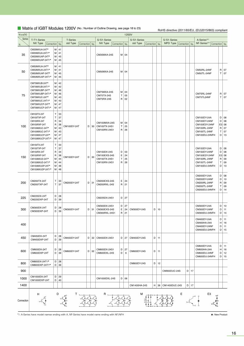
1615
Line-up of IGBT Modules
1700 V IGBT Module 1200 V Diode Module 1700 V Diode Module
50
75
100
150
200
225
300
400
450
600
1000
■ Matrix of IGBT Modules 650V/600V (No.: Number of outline drawing, see page 18 to 23)
650V 600V
Series
Connection
Connection
IC(A)
VCES(V)
D T R M
RoHS directive (2011/65/EU, (EU)2015/863) compliant
RoHS directive (2011/65/EU, (EU)2015/863) compliant■ Matrix of Power Modules for 3-level Inverter (No.: Number of outline drawing, see page 19 to 21)
1200 V IGBT Module
Diode moduleIGBT module
IC/IF
VCES/VRRM
400
450
500
600
800
1000
1400
SC1
3511
★: New Product*Connection of diode module and IGBT module are different.
HHC2 SC1
T/T1-SeriesNX Type
T/S/S1-Seriesstd Type
T-Seriesstd Type
A-SeriesNX Type
NF-Series NF-SeriesNFH Type
CM75MXUB-13T★
CM75MXUB-13T1★
CM75MXUBP-13T★
CM75MXUBP-13T1★
CM100TX-13TCM100TXP-13TCM100MXUB-13T★
CM100MXUB-13T1★
CM100MXUBP-13T★
CM100MXUBP-13T1★
CM100MXUD-13T★
CM100MXUD-13T1★
CM100MXUDP-13T★
CM100MXUDP-13T1★
CM150TX-13TCM150TXP-13TCM150RX-13TCM150RXP-13TCM150MXUD-13T★
CM150MXUD-13T1★
CM150MXUDP-13T★
CM150MXUDP-13T1★
CM200TX-13TCM200TXP-13TCM200RX-13TCM200RXP-13T
CM300DX-13TCM300DXP-13T
CM450DX-13TCM450DXP-13T
CM600DX-13TCM600DXP-13T
CM400ST-24S1CM400C1Y-24S
C1 32CM450C1Y-24T★
C2 36CM500C2Y-24S
C1 32CM600C1Y-24T
H 36CM1400HA-24S
MMMM
D 30
D 30
D 30
D 31
D 31
D 32
D 03
D 03 D 08
D 10
D 11
R 02
R 02
MR
0102
M 01
TTMMMMMMMM
TTRRMMMM
TTRR
DD
DD
DD
42424646
33374242464644444848
3337343844444848
33373438
2839
2839
2839
CM100DY-13T
CM150DY-13T
CM200DY-13T
CM300DY-13T
CM400DY-13T
CM600DY-13T
CM75MX-12A
CM100MX-12ACM100RX-12A
CM150RX-12A
CM200RX-12A
CM300DX-12A
CM400DX-12A
CM75TL-12NFCM75RL-12NF
CM100TL-12NFCM100RL-12NF
CM150DY-12NFCM150TL-12NFCM150RL-12NF
CM200DY-12NF CM200TL-12NFCM200RL-12NF
CM300DY-12NF
CM400DY-12NF
CM600DY-12NF
CM100DUS-12F
CM150DUS-12F
CM200DU-12NFH
CM300DU-12NFH
CM400DU-12NFH
CM600DU-12NFH
TR
0707
DTR
080707
DTR
080909
TR
0707
D 14
D 13
D 13
D 13
D 14
D 15
S/S1-Seriesstd Type
S/S1-Seriesstd Type
S/S1-Seriesstd Type
H 36CM1000HA-34S
H 36CM800HA-34S
H 36CM600HA-34S
H 36RM1400HA-24S★
D 32RM600DY-34S
D 32RM800DY-34S
No.Connection No.Connection
No.Connection No.Connection No.Connection No.Connection
No.Connection No.Connection No.Connection
★: New Product
CM50MXUB-13T★
CM50MXUB-13T1★
CM50MXUBP-13T★
CM50MXUBP-13T1★
MMMM
42424646
D
■ Matrix of IGBT Modules 1200V (No.: Number of Outline Drawing, see page 18 to 23) RoHS directive (2011/65/EU, (EU)2015/863) compliant
CM35MXUA-24T★
CM35MXUA-24T1★
CM35MXUAP-24T★
CM35MXUAP-24T1★
MMMM
41414545
MMMM
41414545
MMMMMMMM
4242464643434747
TTRRMMMM
3337343843434747
TTRRMMMM
3337343844444848
TT
3337
DD
2839
DD
2839
DD
2839
DD
2839
DD
2940
1200V
Series
IC
VCES(V)
T/T1-SeriesNX Type
T-Seriesstd Type
S/S1-SeriesNX Type
S/S1-Seriesstd Type
S/S1-SeriesMPD Type
A-Series※1
NF-Series※1
Connection
★: New Product
35
50
75
100
150
200
225
300
400
450
800
900
1000
1400
600
D R MT E E3H
CM50MXUA-24T★
CM50MXUA-24T1★
CM50MXUAP-24T★
CM50MXUAP-24T1★
CM75MXUB-24T★
CM75MXUB-24T1★
CM75MXUBP-24T★
CM75MXUBP-24T1★
CM75MXUC-24T★
CM75MXUC-24T1★
CM75MXUCP-24T★
CM75MXUCP-24T1★
CM100TX-24TCM100TXP-24TCM100RX-24TCM100RXP-24TCM100MXUC-24T★
CM100MXUC-24T1★
CM100MXUCP-24T★
CM100MXUCP-24T1★
CM150TX-24TCM150TXP-24TCM150RX-24TCM150RXP-24TCM150MXUD-24T★
CM150MXUD-24T1★
CM150MXUDP-24T★
CM150MXUDP-24T1★
CM225DX-24TCM225DXP-24T
CM450DX-24TCM450DXP-24T
CM1000DX-24TCM1000DXP-24T
DD
2839
CM800DX-24T1★
CM800DXP-24T1★
CM200TX-24TCM200TXP-24T
CM300DX-24TCM300DXP-24T
CM600DX-24TCM600DXP-24T
CM100DY-24T
CM150DY-24T
CM200DY-24T
CM300DY-24T
CM450DY-24T
CM600DY-24T
CM35MXA-24S
CM50MXA-24S
CM75MXA-24SCM75TX-24SCM75RX-24S
CM100MXA-24SCM100TX-24S1CM100RX-24S1
CM150DX-24SCM150EXS-24SCM150TX-24S1CM150RX-24S1
CM200EXS-24SCM200RXL-24S
CM225DX-24S1
CM300DX-24S1CM300EXS-24SCM300RXL-24S1
CM450DX-24S1
CM600DX-24S1CM600DXL-24S
CM1000DXL-24S
CM300DY-24S
CM450DY-24S
CM600DY-24S
CM800DY-24S
CM1400HA-24S
CM900DUC-24S
CM1400DUC-24S
CM50RL-24NFCM50TL-24NF
CM75RL-24NFCM75TL24NF
CM100DY-24ACM100DY-24NFCM100E3Y-24NFCM100RL-24NFCM100TL-24NFCM100DU-24NFH
CM150DY-24ACM150DY-24NFCM150E3Y-24NFCM150RL-24NFCM150TL-24NFCM150DU-24NFH
CM200DY-24ACM200DY-24NFCM200RL-24NFCM200TL-24NFCM200DU-24NFH
CM300DY-24ACM300DY-24NFCM300DU-24NFH
CM400DY-24ACM400HA-24ACM400DY-24NFCM400DU-24NFH
CM600DY-24ACM600HA-24ACM600DU-24NFCM600DU-24NFH
*1: A-Series have model namse ending with A, NF-Series have model name ending with NF/NFH
D 32
D 32
D 31
D 31
D 30
D 30
D 06
DD
276
D 27
DER
272421
D 27
ER
2421
DETR
03242526
MTR
042526
MTR
040502
M 04
M 04
D 10
D 11
D 11
D 12
H 36
DHDD
11161215
DHDD
11161115
DDD
101114
DDRTD
0810090914
DDE3RTD
080808090913
DDE3RTD
080808070713
RT
0707
RT
0707
D 17
D 17
No.Connection No.Connection No.Connection No.Connection No.Connection No.Connection
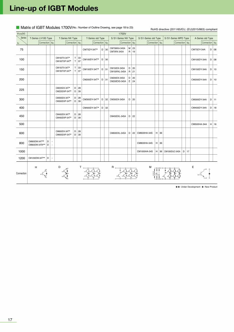
1817
Line-up of IGBT Modules
Connection
■ Matrix of IGBT Modules 1700V(No.: Number of Outline Drawing, see page 18 to 23) RoHS directive (2011/65/EU, (EU)2015/863) compliant1700V
Series
IC
VCES(V)
T-Series NX TypeT-Series LV100 Type T-Series std Type S/S1-Series NX Type S/S1-Series std Type S/S1-Series MPD Type A-Series std Type
D R MT
★★: Under Development ★: New Product
EH
225 CM225DX-34T★CM225DXP-34T★
DD
2839
450 CM450DX-34T★CM450DXP-34T★ CM450DXL-34SA
DD
2839 D 22
600 CM600DX-34T★CM600DXP-34T★ CM600DXL-34SA CM600HA-34SD
D2839 D 22 H 36
1000 CM1000HA-34S CM1000DUC-34SAH 36 D 17
75 CM75DY-34T★ CM75MXA-34SACM75RX-34SA
CM75DY-34AD 30 MR
2319
D 08
100 CM100TX-34T★CM100TXP-34T★
CM100DY-34T★ CM100DY-34ATT
3337
D 30 D 08
150 CM150TX-34T★CM150TXP-34T★
CM150DY-34T★ CM150DX-34SACM150RXL-34SA
CM150DY-34ATT
3337
D 31 DR
2021
D 10
200 CM200DY-34T★CM200DX-34SACM200EXS-34SA CM200DY-34AD 31
DE
2024 D 10
300 CM300DX-34T★CM300DXP-34T★
CM300DY-34T★ CM300DX-34SA CM300DY-34ADD
2839
D 32 D 20 D 11
400 CM400DY-34T★ CM400DY-34AD 32 D 18
500 CM500HA-34A H 16
800 CM800HA-34S H 36CM800DW-34T★★CM800DW-34TA★★
DD
--
1200 CM1200DW-34T★★ D -
No.Connection No.Connection No.Connection No.Connection No.Connection No.Connection No.Connection
■ Outline Drawing of IGBT Modules
CM200TL/RL-12NFCM150,200TL/RL-24NF
09
2020
16.5
18
110±0.5(6.05) (6.05)11.7262617.5
135
10.5
10.5
18.7
110
10.5
10.5
10.5 10.5
(13)
48.7
513
.7526
.54
4-φ5.5
78±
0.5
(6.0
5)
2530.5 25 (13)1146.3
13
24.1
(SCRE
WING
DEPT
H)
6-M5 NUTS
(6.0
5)+1 –0
.5
LABEL
MOUNTINGHOLES
08 CM150,200,300DY-12NFCM100,150DY-24NF CM100,150,200DY-24ACM75,100DY-34ACM100,150E3Y-24NF
TAB#110,t=0.5
80±0.25
94
48 13
47.5
21.2
184
121212
2323 1717
2-φ6.5MOUNTING HOLES
3-M5 NUTS
7716 16 16
LABEL29+1
.0–0
.5
CM75,100,150TL/RL-12NFCM50,75,100TL/RL-24NF
07
2-φ5.5
5511.
7532
(13.5)
106±0.5
13.627
17 1740.78
12011
6-M5NUTS
35
(19.75)
10.75
22 23 23 23
163 23.212
22 (SCR
EWIN
G DE
PTH)
12
1212
12 12 12
+1 –0.5
MOUNTINGHOLES
06CM600,1000DXL-24S
φ0.5*All dimensions with a tolerance of
27262524232221201918171615141312111098765
28293031
34
33
32
353637383940
4142434445464748495051525354555657585960616263
1
2
3
4
A
4-ø5.5MOUNTINGHOLES
110±
0.5
10.74
4.05
41.2
249
.72
3.6
7.75
117.
2
94.5
2222
27.53
22
6
110±0.5
16.9
117.23.6 94.57.75
137
6.5
121.
7
39
12
39
10.53
39
15.2419.0515.2415.24
(21.14)
(20.5
)
121.7
152
(SC
REW
ING
DEP
TH)
LABEL 17 +1 -0
.5
3.5
13
7 13
19.24
6-M6 N
UTS
13.515.14
3.81
3.81
3.81
(3)(6
.5)
05 CM75TX-24S
3.81
3.813.81
15.2415.24
110±0.5
50±
0.5
57.562
9994.5
114.06
39
24.52
15 11.43 11.43 11.43 11.43 11.43 3.81
15.24 3.81
3.81
11.43
11.66
3.81
11.43
3.5
11.66
3.75
3.81
3.81
3.81
3.81
3.81
3.81
3.81
3.81
3.81
3.81
3.81
3.81
3.813.81
4.060.8
3.81
7.75
121.7
4-φ5.5MOUNTINGHOLES
LABEL
1 2 3 4 5 6 7 8 9 10 11 12 13 14 15 16 17 18 19 20 21 22
5253 51 50 49 48 47 46 45 44 43 42 41 40 39 38 37 36 35 34 33 32 31
2324252627282930
6160595857565554
04 CM35,50,75,100MXA-24S
22.8611.4311.43
11.4311.4311.4311.4315
11.4313.094.06
50±
0.5
99110±0.5
94.5
118.1
393.
5
57.5
62
3.81
0.8
3.81
3.81
3.81
3.81
3.81
3.81
3.81
3.81
3.81
3.81
3.81
3.81
3.81
3.813.81
3.813.81
3.81
3.81
3.81
11.43
11.66
11.43
11.66
4.2
121.7
4-φ5.5MOUNTINGHOLES
LABEL
1 2 3 4 5 6 7 8 9 10 11 12 13 14 15 16 17 18 19 20 21 22
5253 51 50 49 48 47 46 45 44 43 42 41 40 39 38 37 36 35 34 33 32 31
2324252627282930
6160595857565554
03 CM300,400DX-12A CM150,200DX-24S
02 CM100,150,200RX-12A CM75RX-24S
01 CM75,100MX-12A
53
54
61
1 22
31
30
23
99
121.7*118.1110±0.5
94.5
*58
.4
0
0.8
3950
±0.
557
.5 62
*4.2
*15.48*11.66
*4.
06
*13
.09
*16
.9*
15*
18.8
*30
.24
*34
.04
*45
.48
*49
.28
*60
.72
*64
.52
*75
.96
*79
.76
*91
.2*
950(7
.75)
*28
.33
*32
.14
*66
.43
*70
.24
*81
.67
*85
.48
*89
.29
*93
.1*
96.9
1
*15.48*19.28*30.72*34.52
*47
.38
*51
.19
*26.9*23.1
*38.34*34.52
0 0 3.75
0.8
3.5 LABEL
4-φ5.5MOUNTINGHOLES
φ0.5*All dimensions with a tolerance of φ0.5*All dimensions with a tolerance of φ0.5*All dimensions with a tolerance of
Unit :mm
34 33 32 31 30 29 28 27 26 25 24 23 22 21 20 19 18 17 16 15 14 13
12111098765
1 2 3 4
35
36
A
6-M5 NUTS
22.8622.86
8.5612 17
22.8620.7113.5
13.6
4
6.5
6.5
(21.
14)
(21.14)
121.7
9994.5
393.
7557
.5 6277
.1
7.75
68.
512
392214
17
110±0.5
50±0
.5
136.9
4-ø5.5MOUNTING HOLES
LABEL
11.43 11.43 11.43 11.43 11.4315
3.81
(20.
5)
3.81
3.81
3.81
3.81
3.81
0.8
3.5
46 45 44 43 42 41 40 39 38 37 36 35 34 33 32 31 30 29 28 27 26 25
24
23
1 2 3 4 5 6 7 8 9 10 11 12 13 14 15 16 17 18 19 20 21 22
47
48
A 15
94.5
110±0.5
41.66
137
6.5
54.2
4.
2
3.75
57
.550
±0.522
6
49.53
99
121.7
152
3.81
22.86
3.81
3.81
17
62
1239
4-M6 NUTS
(14)
(14)
4-ø5.5MOUNTING HOLES
LABEL
6.5
17+1 -0
.5
3.5
13.5
7.75
(13.5)
(21.14)
(SC
REW
ING
DEP
TH)
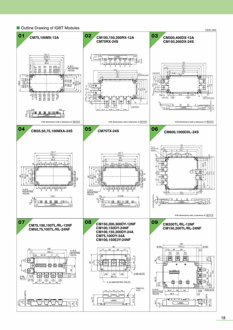
1817
Line-up of IGBT Modules
Connection
■ Matrix of IGBT Modules 1700V(No.: Number of Outline Drawing, see page 18 to 23) RoHS directive (2011/65/EU, (EU)2015/863) compliant1700V
Series
IC
VCES(V)
T-Series NX TypeT-Series LV100 Type T-Series std Type S/S1-Series NX Type S/S1-Series std Type S/S1-Series MPD Type A-Series std Type
D R MT
★★: Under Development ★: New Product
EH
225 CM225DX-34T★CM225DXP-34T★
DD
2839
450 CM450DX-34T★CM450DXP-34T★ CM450DXL-34SA
DD
2839 D 22
600 CM600DX-34T★CM600DXP-34T★ CM600DXL-34SA CM600HA-34SD
D2839 D 22 H 36
1000 CM1000HA-34S CM1000DUC-34SAH 36 D 17
75 CM75DY-34T★ CM75MXA-34SACM75RX-34SA
CM75DY-34AD 30 MR
2319
D 08
100 CM100TX-34T★CM100TXP-34T★
CM100DY-34T★ CM100DY-34ATT
3337
D 30 D 08
150 CM150TX-34T★CM150TXP-34T★
CM150DY-34T★ CM150DX-34SACM150RXL-34SA
CM150DY-34ATT
3337
D 31 DR
2021
D 10
200 CM200DY-34T★CM200DX-34SACM200EXS-34SA CM200DY-34AD 31
DE
2024 D 10
300 CM300DX-34T★CM300DXP-34T★
CM300DY-34T★ CM300DX-34SA CM300DY-34ADD
2839
D 32 D 20 D 11
400 CM400DY-34T★ CM400DY-34AD 32 D 18
500 CM500HA-34A H 16
800 CM800HA-34S H 36CM800DW-34T★★CM800DW-34TA★★
DD
--
1200 CM1200DW-34T★★ D -
No.Connection No.Connection No.Connection No.Connection No.Connection No.Connection No.Connection
■ Outline Drawing of IGBT Modules
CM200TL/RL-12NFCM150,200TL/RL-24NF
09
2020
16.5
18
110±0.5(6.05) (6.05)11.7262617.5
135
10.5
10.5
18.7
110
10.5
10.5
10.5 10.5
(13)
48.7
513
.7526
.54
4-φ5.5
78±
0.5
(6.0
5)
2530.5 25 (13)1146.3
13
24.1
(SCRE
WING
DEPT
H)
6-M5 NUTS
(6.0
5)+1 –0
.5
LABEL
MOUNTINGHOLES
08 CM150,200,300DY-12NFCM100,150DY-24NF CM100,150,200DY-24ACM75,100DY-34ACM100,150E3Y-24NF
TAB#110,t=0.5
80±0.25
94
48 13
47.5
21.2
184
121212
2323 1717
2-φ6.5MOUNTING HOLES
3-M5 NUTS
7716 16 16
LABEL29+1
.0–0
.5
CM75,100,150TL/RL-12NFCM50,75,100TL/RL-24NF
07
2-φ5.5
5511.
7532
(13.5)
106±0.5
13.627
17 1740.78
12011
6-M5NUTS
35
(19.75)
10.75
22 23 23 23
163 23.212
22 (SCR
EWIN
G DE
PTH)
12
1212
12 12 12
+1 –0.5
MOUNTINGHOLES
06CM600,1000DXL-24S
φ0.5*All dimensions with a tolerance of
27262524232221201918171615141312111098765
28293031
34
33
32
353637383940
4142434445464748495051525354555657585960616263
1
2
3
4
A
4-ø5.5MOUNTINGHOLES
110±
0.5
10.74
4.05
41.2
249
.72
3.6
7.75
117.
2
94.5
2222
27.53
22
6
110±0.5
16.9
117.23.6 94.57.75
137
6.5
121.
7
39
12
39
10.53
3915.2419.0515.2415.24
(21.14)
(20.5
)
121.7
152
(SC
REW
ING
DEP
TH)
LABEL 17 +1 -0
.5
3.5
13
7 13
19.24
6-M6 N
UTS
13.515.14
3.81
3.81
3.81
(3)(6
.5)
05 CM75TX-24S
3.81
3.813.81
15.2415.24
110±0.5
50±
0.5
57.562
9994.5
114.06
39
24.52
15 11.43 11.43 11.43 11.43 11.43 3.81
15.24 3.81
3.81
11.43
11.66
3.81
11.43
3.5
11.66
3.75
3.81
3.81
3.81
3.81
3.81
3.81
3.81
3.81
3.81
3.81
3.81
3.81
3.813.81
4.060.8
3.81
7.75
121.7
4-φ5.5MOUNTINGHOLES
LABEL
1 2 3 4 5 6 7 8 9 10 11 12 13 14 15 16 17 18 19 20 21 22
5253 51 50 49 48 47 46 45 44 43 42 41 40 39 38 37 36 35 34 33 32 31
2324252627282930
6160595857565554
04 CM35,50,75,100MXA-24S
22.8611.4311.43
11.4311.4311.4311.4315
11.4313.094.06
50±
0.5
99110±0.5
94.5
118.1
393.
5
57.5
62
3.81
0.8
3.81
3.81
3.81
3.81
3.81
3.81
3.81
3.81
3.81
3.81
3.81
3.81
3.81
3.813.81
3.813.81
3.81
3.81
3.81
11.43
11.66
11.43
11.66
4.2
121.7
4-φ5.5MOUNTINGHOLES
LABEL
1 2 3 4 5 6 7 8 9 10 11 12 13 14 15 16 17 18 19 20 21 22
5253 51 50 49 48 47 46 45 44 43 42 41 40 39 38 37 36 35 34 33 32 31
2324252627282930
6160595857565554
03 CM300,400DX-12A CM150,200DX-24S
02 CM100,150,200RX-12A CM75RX-24S
01 CM75,100MX-12A
53
54
61
1 22
31
30
23
99
121.7*118.1110±0.5
94.5
*58
.4
0
0.8
3950
±0.
557
.5 62
*4.2
*15.48*11.66
*4.
06
*13
.09
*16
.9*
15*
18.8
*30
.24
*34
.04
*45
.48
*49
.28
*60
.72
*64
.52
*75
.96
*79
.76
*91
.2*
950(7
.75)
*28
.33
*32
.14
*66
.43
*70
.24
*81
.67
*85
.48
*89
.29
*93
.1*
96.9
1
*15.48*19.28*30.72*34.52
*47
.38
*51
.19
*26.9*23.1
*38.34*34.52
0 0 3.75
0.8
3.5 LABEL
4-φ5.5MOUNTINGHOLES
φ0.5*All dimensions with a tolerance of φ0.5*All dimensions with a tolerance of φ0.5*All dimensions with a tolerance of
Unit :mm
34 33 32 31 30 29 28 27 26 25 24 23 22 21 20 19 18 17 16 15 14 13
12111098765
1 2 3 4
35
36
A
6-M5 NUTS
22.8622.86
8.5612 17
22.8620.7113.5
13.6
4
6.5
6.5
(21.
14)
(21.14)
121.7
9994.5
393.
7557
.5 6277
.1
7.75
68.
512
392214
17
110±0.5
50±0
.5
136.9
4-ø5.5MOUNTING HOLES
LABEL
11.43 11.43 11.43 11.43 11.4315
3.81
(20.
5)
3.81
3.81
3.81
3.81
3.81
0.8
3.5
46 45 44 43 42 41 40 39 38 37 36 35 34 33 32 31 30 29 28 27 26 25
24
23
1 2 3 4 5 6 7 8 9 10 11 12 13 14 15 16 17 18 19 20 21 22
47
48
A 15
94.5
110±0.5
41.66
137
6.5
54.2
4.
2
3.75
57
.550
±0.522
6
49.53
99
121.7
152
3.81
22.86
3.81
3.81
17
62
1239
4-M6 NUTS
(14)
(14)
4-ø5.5MOUNTING HOLES
LABEL
6.5
17+1 -0
.5
3.5
13.5
7.75
(13.5)
(21.14)
(SC
REW
ING
DEP
TH)
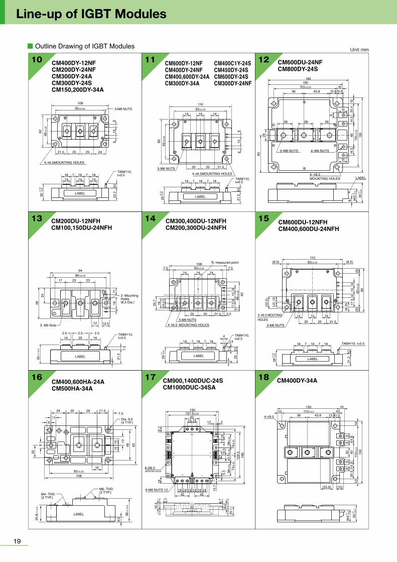
■ Outline Drawing of IGBT Modules
CM400DY-34A18
130
36 43.8 13.8 11.510110±0.2
1013010
1010
20.5
14.5
4014
.511
0±0.
2
99
920
9
(25.9) (15)
4-φ6.5
24.5
+1 –0.5
35+1 –0
.5
17 CM900,1400DUC-24SCM1000DUC-34SA
LABEL
C2G
2E2 G1
E1C1
C1E2
C2E1
MOUNTING HOLES
(SC
REW
ING
DEPT
H)
(SC
REW
ING
DEPT
H)
9-M6 NUTS 12
18
42 42
15.7
42
150
166
42.5
\0.2
538
\0.2
5
137.5\0.25
74\0
.25
14 1414141414
1414
25.1
5.5
10.5
2111
19
129.
5
212
15.7
74\0
.25
38\0
.25
8-Ø6.5
6.7
16.5
16.5
6.7
16 CM400,600HA-24ACM500HA-34A
93±0.25
108
16
29
67.9
17.57.5
10
20
9 10 1348 62
Dia - 6.5(4 TYP.)
24 20
25.8
+1/-0
.5
36+1
/-0.5
(8.5)
M6 - THD.(2 TYP.)M4 - THD.
(2 TYP.)
LABEL
14 CM300,400DU-12NFHCM200,300DU-24NFH
TAB#110,t=0.5
29+1 –0
.58.8
58.2
5
4
4-φ6.5 MOUNTING HOLES3-M6 NUTS
108
62
18 187 7 18
8.522
2.84
7.56
156
717
.5
14 14 14
25 2.521.525
Tc measured point7.57.5
LABEL
25.7
18
48±
0.25
93±0.25
13 CM200DU-12NFHCM100,150DU-24NFH
94
2317
2448
30+1
/-0.
5
421
.2
4
7.5
1118
2 - MountingHoles (6.5 Dia.)
723
3 - M5 Nuts
80±0.25
13.512
16 1625
LABEL
2.5 2.52.5 TAB#110,t=0.5
CM600DU-24NFCM800DY-24S
12
140130
110±0.25
20
1020
.414
.5
9
14.5
408
130
110±
0.25
65
36
3–M8 NUTS 4–M4 NUTS
43.8 13.8 11.510
2626 26
15
35+1 –0
.5
24.5
+1 –0.5
15
4–φ6.5MOUNTING HOLES LABEL
11 CM600DY-12NFCM400DY-24NFCM400,600DY-24ACM300DY-34A
CM400C1Y-24SCM450DY-24SCM600DY-24SCM300DY-24NF
62±
0.25
80
25 25 21.5
4-φ6.5MOUNTING HOLES
8.521
.2
7718
14 14 14
18 18 TAB#110,t=0.5
3-M6 NUTS
LABEL29+1
.0–0
.5
615
6
93±0.25
110
2019
Line-up of IGBT Modules
15 CM600DU-12NFHCM400,600DU-24NFH
3-M6 NUTS
4-φ6.5 MOUTINGHOLES
(8.5)(2
2.2)
9.25(
10)
(8.5)
(9)
(9)
93±0.25
62±
0.25
110
17.5
18.2
5
80
615
6
2514 14 14
25 21.5
LABEL29+1
.0–0
.5
21.2
8.518 18 187 7 TAB#110. t=0.5
CM400DY-12NFCM200DY-24NFCM300DY-24ACM300DY-24SCM150,200DY-34A
10
48±
0.25
62
21.5 25 25 24
4-φ6.5MOUNTING HOLES
8.522
.2
771814 14 14
18 18TAB#110,t=0.5
3-M6 NUTS
LABEL30+1
.0–0
.5
615
693±0.25
108
Unit :mm ■ Outline Drawing of IGBT Modules Unit :mm
CM225DX-24S1CM300DX-24S1CM450DX-24S1CM600DX-24S1
LABEL
152137
121.7
94.57.75110±0.5
4-φ5.5MOUNTING HOLES
(SCR
EWIN
G DE
PTH)
37.72±0.333.91±0.3
0.45±
0.3
57.9
5±0.
3
7.24±
0.3
11.0
5±0.
3
60.5
8±0.
364
.39±
0.3
87.2
5±0.
3
50±
0.5
39 2214
12
(6.5)(15.64)
(15.64
) 3.75
57.5 62
714
17+1 -0
.53.5
(7.75
)
6
4-M6 NUTS
(13.5)(15.14)
27
77.1
CM100RX-24S1CM150RX-24S1
136.9121.7
94.157.75(15.64)
6.5
110±0.5
50±
0.5
57.5
6-M5 NUTS22.8622.8622.8620.7113.5
126 8
2214
13.6
411.5
39
3.75
62
4-φ5.5MOUNTING HOLES
7.24±
0.2
11.0
6±0.
2
22.4
8±0.
226
.3±0.
2
37.7
2±0.
241
.54±
0.2
52.9
6±0.
256
.78±
0.2
68.2±
0.2
72.0
2±0.
2
83.4
4±0.
287
.26±
0.2
106.
3±0.
2
(94.
5)
(7.7
5) 0
LABEL
24CM75MXA-34SA
121.7
94.5
0
(57.5)
62
4-φ5.5 MOUNTING HOLES
3.75
0
4-R6.5
(41.
9)
7.75(102.3)110±0.5
38.27±0.2
23.04±0.2
34.46±0.2
34.0
257
.5
(3.75)
19.22±0.215.42±0.2
106.3±0.211.8±0.20.8
3.5
4
5.34±
0.2
50±
0.5
9.15±
0.2
42.08±0.238.28±0.234.46±0.2
23.04±0.219.22±0.215.42±0.2
7.24±
0.2
11.06±
0.2
22.48±
0.2
26.3±
0.2
37.72±
0.2
41.54±
0.2
52.96±
0.2
56.77±
0.2
60.58±
0.2
72.01±
0.2
75.82±
0.2
79.63±
0.2
(94.5)
(7.75) 0
0
20.58±
0.2
35.82±
0.239
.63±
0.2
51.06±
0.254
.87±
0.258
.68±
0.2
81.54±
0.285
.35±
0.289
.16±
0.2
24.39±
0.2
23CM450DXL-34SACM600DXL-34SA
121.7(20.5)
3.57
(3)
17 +1-0.5
4-φ5.5
121.
7
0
147
0
2227.5322
137
152
3.6
13.5
19.2410.74 88.537.75
6-M6 NUTS(SCREWING DEPTH)
15.14
MOUNTING HOLES
(6.5
)(1
5.64
)
41.22 3922
(8)(12)
49.72
105.9±0.311.36±0.3
117.66±0.3117.21±0.3
105.85±0.3
96.7±0.3
81.46±0.377.65±0.3
58.6±0.3
110±
0.5
9.15±
0.312
.96±
0.3
43.36±0.339.55±0.3
24.31±0.320.5±0.3
94.5±0.3106.3±0.3
24.31±0.320.05±0.3
11.8±0.3
11.35±0.3
110±0.5
22
CM200RXL-24SCM300RXL-24S1CM150RXL-34SA
13
(7.7
5) 07.
24±
0.2
11.0
6±0.
2
110±0.5
110±
0.5
3.6 11
.539
13.5
14.1
422
126
8
6.5
22.4
8±0.
226
.3±
0.2
37.7
2±0.
241
.54±
0.2
52.9
6±0.
256
.78±
0.2
68.2±
0.2
72.0
2±0.
2
83.4
4±0.
287
.26±
0.2
106.
3±0.
2 3.5
6-M522.8622.8622.8620.71
(15.64)
13.585.5818.06
15.1
121.
711
7.2
NUTS
121.7
94.55.864-φ5.5 MOUNTING HOLES
7.75
(94.
5)
(20.
5)LABEL
21CM150DX-34SACM200DX-34SACM300DX-34SA
152137
121.7(15.14)
94.5
(6.5)(15.64) 0
8612
142239
110±0.5
7.24±
0.3
11.0
5±0.
3
60.5
8±0.
364
.39±
0.3
50±
0.5
87.2
5±0.
3
37.72±0.333.91±0.3
57.9
5±0.
30.
45±
0.3
14
7(S
CR
EWIN
G D
EPTH
)
(13.5)7.75
4-φ5.5
4-M6 NUTS
MOUNTING HOLES(94.
5) 3.75
57.5
62
3.5
17+1
-0.5
19
25
1048962
19.05
6257.5
13.1 13
.1
16.4
17
(5.6
)
503.
753922
1417
105
4.2
46.573.71
7.754-φ5.5 MOUNTING HOLES
4-M5 NUT
17.66 3.813.8113.5
LABEL
CM150EXS-24SCM200EXS-24SCM300EXS-24SCM200EXS-34SA
26CM100TX-24S1CM150TX-24S1
121.7
0
(57.5)
4-R6.562
(41.
9)
03.75
0
(102.3)94.57.75
110±0.5
106.31±0.211.8±0.2
43.
5 0.8
16.77±
0.3
42.09±0.338.28±0.334.46±0.3
23.04±0.319.22±0.315.41±0.3
7.24±
0.311
.06±
0.3
22.48±
0.3
37.72±
0.341
.54±
0.3
52.96±
0.356
.78±
0.3
72.02±
0.3
83.44±
0.387
.26±
0.3
15.41±0.319.22±0.323.04±0.3
34.46±0.338.27±0.342.09±0.3
4-φ5.5 MOUNTING HOLES
(94.5)
57.5
0
68.2±
0.3
26.3±
0.3
50±
0.5
20.58±
0.324
.39±
0.3
39.63±
0.343
.44±
0.347
.25±
0.3
62.49±
0.366
.3±0.3
70.11±
0.3
85.35±
0.389
.16±
0.3LABEL
20CM75RX-34SA
136.9121.7110±0.594.57.75(15.64)
7.24±
0.2
110.
6±0.
2
22.4
8±0.
226
.3±
0.2
37.7
2±0.
241
.54±
0.2
52.9
6±0.
256
.78±
0.2
68.2±
0.2
72.2±
0.2
83.4
4±0.
287
.26±
0.2
106.
3±0.
2
(7.
75)
(94
.5)0
6.5
13.5
13.6
414
223911
.577
.1
12
8
50±
0.5
3.75
57.5
62
20.71 22.86 22.86 22.86 6-M5 NUTS
MOUNTING HOLES4-Ø5.5
B
LABEL
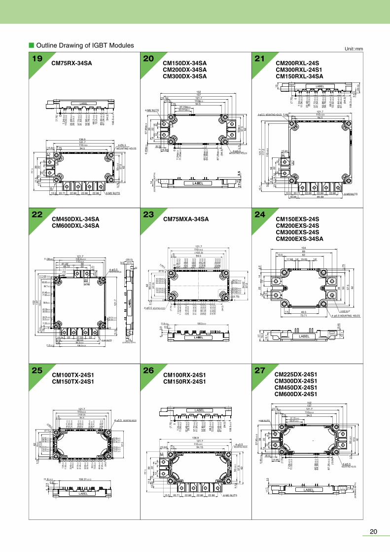
■ Outline Drawing of IGBT Modules
CM400DY-34A18
130
36 43.8 13.8 11.510110±0.2
1013010
1010
20.5
14.5
4014
.511
0±0.
2
99
920
9
(25.9) (15)
4-φ6.5
24.5
+1 –0.5
35+1 –0
.5
17 CM900,1400DUC-24SCM1000DUC-34SA
LABEL
C2G
2E2 G1
E1C1
C1E2
C2E1
MOUNTING HOLES
(SC
REW
ING
DEPT
H)
(SC
REW
ING
DEPT
H)
9-M6 NUTS 12
18
42 42
15.7
42
150
166
42.5
\0.2
538
\0.2
5
137.5\0.25
74\0
.25
14 1414141414
1414
25.1
5.5
10.5
2111
19
129.
5
212
15.7
74\0
.25
38\0
.25
8-Ø6.5
6.7
16.5
16.5
6.7
16 CM400,600HA-24ACM500HA-34A
93±0.25
108
16
29
67.9
17.57.5
10
20
9 10 1348 62
Dia - 6.5(4 TYP.)
24 20
25.8
+1/-0
.5
36+1
/-0.5
(8.5)
M6 - THD.(2 TYP.)M4 - THD.
(2 TYP.)
LABEL
14 CM300,400DU-12NFHCM200,300DU-24NFH
TAB#110,t=0.5
29+1 –0
.58.8
58.2
5
4
4-φ6.5 MOUNTING HOLES3-M6 NUTS
108
62
18 187 7 18
8.522
2.84
7.56
156
717
.5
14 14 14
25 2.521.525
Tc measured point7.57.5
LABEL
25.7
18
48±
0.25
93±0.25
13 CM100,150DUS-12FCM200DU-12NFHCM100,150DU-24NFH
94
2317
2448
30+1
/-0.
5
421
.2
4
7.5
1118
2 - MountingHoles (6.5 Dia.)
723
3 - M5 Nuts
80±0.25
13.512
16 1625
LABEL
2.5 2.52.5 TAB#110,t=0.5
CM600DU-24NFCM800DY-24S
12
140130
110±0.25
20
1020
.414
.5
9
14.5
408
130
110±
0.25
65
36
3–M8 NUTS 4–M4 NUTS
43.8 13.8 11.510
2626 26
15
35+1 –0
.5
24.5
+1 –0.5
15
4–φ6.5MOUNTING HOLES LABEL
11 CM600DY-12NFCM400DY-24NFCM400,600DY-24ACM300DY-34A
CM400C1Y-24SCM450DY-24SCM600DY-24SCM300DY-24NF
62±
0.25
80
25 25 21.5
4-φ6.5MOUNTING HOLES
8.521
.2
7718
14 14 14
18 18 TAB#110,t=0.5
3-M6 NUTS
LABEL29+1
.0–0
.5
615
6
93±0.25
110
2019
Line-up of IGBT Modules
15 CM600DU-12NFHCM400,600DU-24NFH
3-M6 NUTS
4-φ6.5 MOUTINGHOLES
(8.5)
(22.
2)
9.25(
10)
(8.5)
(9)
(9)
93±0.25
62±
0.25
110
17.5
18.2
5
80
615
6
2514 14 14
25 21.5
LABEL29+1
.0–0
.5
21.2
8.5
18 18 187 7 TAB#110. t=0.5
CM400DY-12NFCM200DY-24NFCM300DY-24ACM300DY-24SCM150,200DY-34A
10
48±
0.25
62
21.5 25 25 24
4-φ6.5MOUNTING HOLES
8.522
.2
771814 14 14
18 18TAB#110,t=0.5
3-M6 NUTS
LABEL30+1
.0–0
.5
615
6
93±0.25
108
Unit :mm ■ Outline Drawing of IGBT Modules Unit :mm
CM225DX-24S1CM300DX-24S1CM450DX-24S1CM600DX-24S1
LABEL
152137
121.7
94.57.75110±0.5
4-φ5.5MOUNTING HOLES
(SCR
EWIN
G DE
PTH)
37.72±0.333.91±0.3
0.45±
0.3
57.9
5±0.
3
7.24±
0.3
11.0
5±0.
3
60.5
8±0.
364
.39±
0.3
87.2
5±0.
3
50±
0.5
39 2214
12
(6.5)(15.64)
(15.64
) 3.75
57.5 62
714
17+1 -0
.53.5
(7.75
)
6
4-M6 NUTS
(13.5)(15.14)
27
77.1
CM100RX-24S1CM150RX-24S1
136.9121.7
94.157.75(15.64)
6.5
110±0.5
50±
0.5
57.5
6-M5 NUTS22.8622.8622.8620.7113.5
126 8
2214
13.6
411.5
39
3.75
62
4-φ5.5MOUNTING HOLES
7.24±
0.2
11.0
6±0.
2
22.4
8±0.
226
.3±0.
2
37.7
2±0.
241
.54±
0.2
52.9
6±0.
256
.78±
0.2
68.2±
0.2
72.0
2±0.
2
83.4
4±0.
287
.26±
0.2
106.
3±0.
2
(94.
5)
(7.7
5) 0
LABEL
24CM75MXA-34SA
121.7
94.5
0
(57.5)
62
4-φ5.5 MOUNTING HOLES
3.75
0
4-R6.5
(41.
9)
7.75(102.3)110±0.5
38.27±0.2
23.04±0.2
34.46±0.2
34.0
257
.5
(3.75)
19.22±0.215.42±0.2
106.3±0.211.8±0.20.8
3.5
4
5.34±
0.2
50±
0.5
9.15±
0.2
42.08±0.238.28±0.234.46±0.2
23.04±0.219.22±0.215.42±0.2
7.24±
0.2
11.06±
0.2
22.48±
0.2
26.3±
0.2
37.72±
0.2
41.54±
0.2
52.96±
0.2
56.77±
0.2
60.58±
0.2
72.01±
0.2
75.82±
0.2
79.63±
0.2
(94.5)
(7.75) 0
0
20.58±
0.2
35.82±
0.239
.63±
0.2
51.06±
0.254
.87±
0.258
.68±
0.2
81.54±
0.285
.35±
0.289
.16±
0.2
24.39±
0.2
23CM450DXL-34SACM600DXL-34SA
121.7(20.5)
3.57
(3)
17 +1-0.5
4-φ5.5
121.
7
0
147
0
2227.5322
137
152
3.6
13.5
19.2410.74 88.537.75
6-M6 NUTS(SCREWING DEPTH)
15.14
MOUNTING HOLES
(6.5
)(1
5.64
)
41.22 3922
(8)(12)
49.72
105.9±0.311.36±0.3
117.66±0.3117.21±0.3
105.85±0.3
96.7±0.3
81.46±0.377.65±0.3
58.6±0.3
110±
0.5
9.15±
0.312
.96±
0.3
43.36±0.339.55±0.3
24.31±0.320.5±0.3
94.5±0.3106.3±0.3
24.31±0.320.05±0.3
11.8±0.3
11.35±0.3
110±0.5
22
CM200RXL-24SCM300RXL-24S1CM150RXL-34SA
13
(7.7
5) 07.
24±
0.2
11.0
6±0.
2
110±0.5
110±
0.5
3.6 11
.539
13.5
14.1
422
126
8
6.5
22.4
8±0.
226
.3±
0.2
37.7
2±0.
241
.54±
0.2
52.9
6±0.
256
.78±
0.2
68.2±
0.2
72.0
2±0.
2
83.4
4±0.
287
.26±
0.2
106.
3±0.
2 3.5
6-M522.8622.8622.8620.71
(15.64)
13.585.5818.06
15.1
121.
711
7.2
NUTS
121.7
94.55.864-φ5.5 MOUNTING HOLES
7.75
(94.
5)
(20.
5)LABEL
21CM150DX-34SACM200DX-34SACM300DX-34SA
152137
121.7(15.14)
94.5
(6.5)(15.64) 0
8612
142239
110±0.5
7.24±
0.3
11.0
5±0.
3
60.5
8±0.
364
.39±
0.3
50±
0.5
87.2
5±0.
3
37.72±0.333.91±0.3
57.9
5±0.
30.
45±
0.3
14
7(S
CR
EWIN
G D
EPTH
)
(13.5)7.75
4-φ5.5
4-M6 NUTS
MOUNTING HOLES(94.
5) 3.75
57.5
62
3.5
17+1
-0.5
19
25
1048962
19.05
6257.5
13.1 13
.1
16.4
17
(5.6
)
503.
753922
1417
105
4.2
46.573.71
7.754-φ5.5 MOUNTING HOLES
4-M5 NUT
17.66 3.813.8113.5
LABEL
CM150EXS-24SCM200EXS-24SCM300EXS-24SCM200EXS-34SA
26CM100TX-24S1CM150TX-24S1
121.7
0
(57.5)
4-R6.5
62
(41.
9)
03.75
0
(102.3)94.57.75
110±0.5
106.31±0.211.8±0.2
43.
5 0.8
16.77±
0.3
42.09±0.338.28±0.334.46±0.3
23.04±0.319.22±0.315.41±0.3
7.24±
0.311
.06±
0.3
22.48±
0.3
37.72±
0.341
.54±
0.3
52.96±
0.356
.78±
0.3
72.02±
0.3
83.44±
0.387
.26±
0.3
15.41±0.319.22±0.323.04±0.3
34.46±0.338.27±0.342.09±0.3
4-φ5.5 MOUNTING HOLES
(94.5)
57.5
0
68.2±
0.3
26.3±
0.3
50±
0.5
20.58±
0.324
.39±
0.3
39.63±
0.343
.44±
0.347
.25±
0.3
62.49±
0.366
.3±0.3
70.11±
0.3
85.35±
0.389
.16±
0.3
LABEL
20CM75RX-34SA
136.9121.7110±0.594.57.75(15.64)
7.24±
0.2
110.
6±0.
2
22.4
8±0.
226
.3±
0.2
37.7
2±0.
241
.54±
0.2
52.9
6±0.
256
.78±
0.2
68.2±
0.2
72.2±
0.2
83.4
4±0.
287
.26±
0.2
106.
3±0.
2
(7.
75)
(94
.5)0
6.5
13.5
13.6
414
223911
.577
.1
12
8
50±
0.5
3.75
57.5
62
20.71 22.86 22.86 22.86 6-M5 NUTS
MOUNTING HOLES4-Ø5.5
B
LABEL
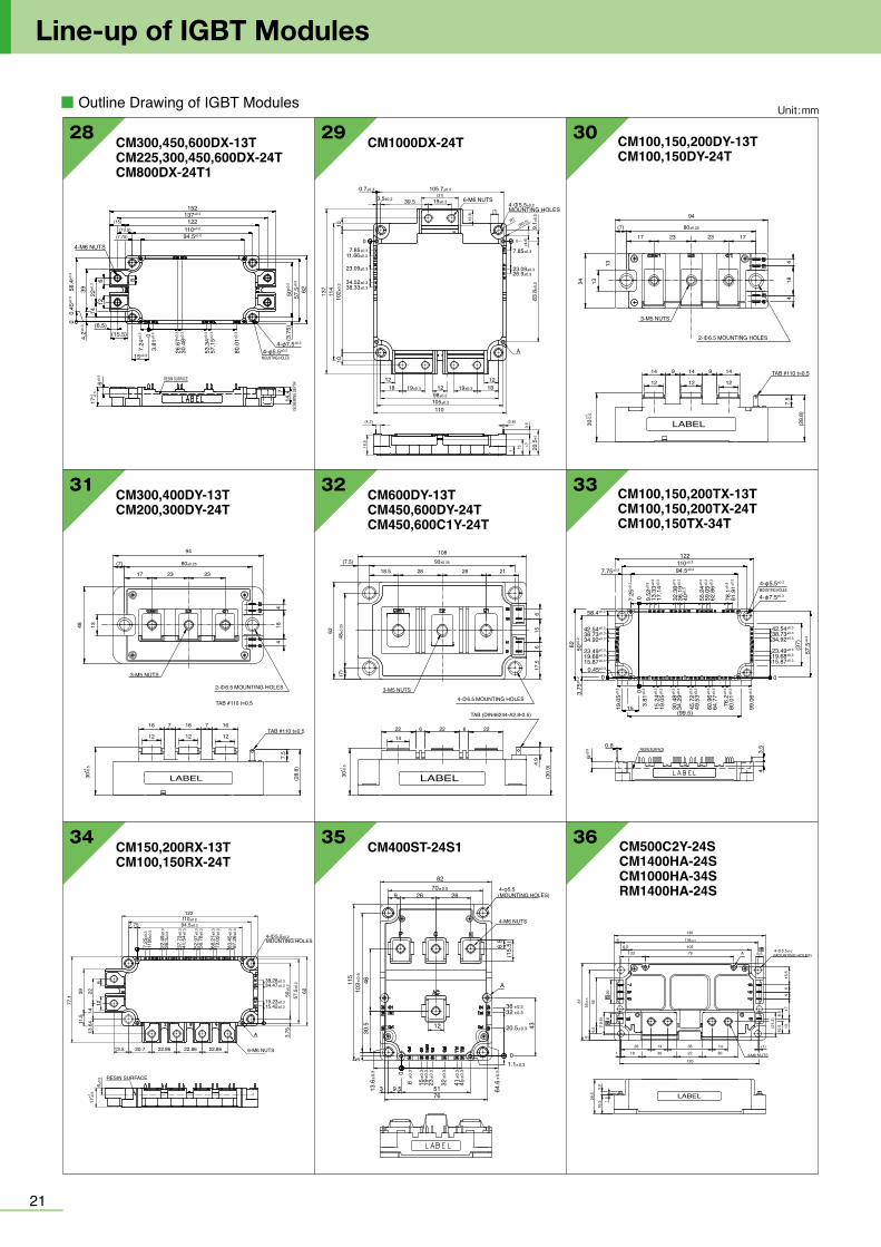
■ Outline Drawing of IGBT Modules
2221
Line-up of IGBT Modules
Unit :mm
3534 36
3231 33
29 3028
CM400ST-24S1
70 0.5±
36 0.3±
A
32 0.3±
20.5 0.3±
1.1 0.3±
64.6
0.3
±
450.
3±
410.
3±
320.
3±
230.
3±
190.
3±
150.
3±
60.
3±
103
0.5
±
13.6
0.3
±
82
26 264-φ5.5
4-M6 NUTS
6.5
43
519.53
0
330
.54611
5
76
12
0
(15.
5)
(MOUNTING HOLES)9
CM100,150,200DY-13TCM100,150DY-24T
80±0.25
30-0
.5+1
(7)
94
23 23 17
184
4
17
13
1334
MOUNTING HOLES
TAB #110 t=0.5
3-M5 NUTS
14 14 1499
12
7.5
(28.
8)
12
LABEL
12
2- 6.5
CM300,400DY-13TCM200,300DY-24T
80±0.25(7)
94
44
181348
2323
3-M5 NUTS
TAB #110 t=0.5
TAB #110 t=0.5
LABEL
16 16 16
12 12 12
7.5
(28.
8)
77
17
MOUNTING HOLES2- 6.5
30-0
.5+1
CM600DY-13TCM450,600DY-24TCM450,600C1Y-24T
93±0.25
48±0
.25
(7.5)108
66
17.5
15
(7)
62
3-M5 NUTS
TAB (DIN46244-A2.8-0.5)
LABEL
22 22 226614
4.9
(30.
9)
18.5 28 28 21
MOUNTING HOLES4- 6.5
30-0
.5+1
CM1000DX-24T
0.7±0.3
3.5±0.2 39.5
105.7±0.3
9.1±
0.2
7.85±0.3
23.09±0.326.9±0.3
83.8
±0.2
19±0.3
20.5
±1
19±0.3
102±
0.2 38.33±0.3
34.52±0.3
23.09±0.3
11.66±0.37.85±0.3
0
1010
137
114
105±0.298±0.2
110
12181218
12
A
19±0.3 6-M6 NUTSMOUNTING HOLES
(31)
(7)
(4.2) (0.8)
3.5
17137
16.5
0
(12.
3)
(4.6
)
R7(R0.5)
4- 5.5±0.2
CM150,200RX-13TCM100,150RX-24T
110±0.294.5±0.2
1106
±0.3
22.4
9±0.
326
.3±0
.3
37.7
3±0.
341
.54±
0.3
52.9
7±0.
356
.78±
0.3
72.0
2±0.
3
87.2
6±0.
3
50±0
.2
38.28±0.334.47±0.3
19.23±0.315.42±0.3
3.75A
6-M6 NUTS22.8622.8622.8620.713.5
RESIN SURFACE
13.6
414
126
223911
.5
77.1 57
.5±0
.2
6±0.
5
17-0
.5+1
62
83.4
5 ±0.
3
68.2
1±0.
3
7.25
±0.3
7.75
122
MOUNTING HOLES4- 5.5±0.2
CM300,450,600DX-13TCM225,300,450,600DX-24TCM800DX-24T1
152137±0.3
122110±0.2
50±0
.2
80.0
1±0.3
57.1
5±0.3
53.3
4±0.3
30.4
8±0.3
26.6
7±0.3
3.81
±0.3
7.24
±0.34.2±0
.3
6±0.5
22±0
.3
58.4
±0.3
0.45
±0.3
3914
8612
0
0
(3.7
5)7
14.4
57.5
±0.2
17+1
-0
.5
62
4-φ5.5±0.2
15±0.3
(15.5)(6.5)
4-φ7.5±0.3
MOUNTING HOLES
RESIN SURFACE
(SCRE
WING
DEPT
H)
94.5±0.2
4-M6 NUTS
(15)
(13.5)(7.75)
CM100,150,200TX-13TCM100,150,200TX-24TCM100,150TX-34T
57.5
±0.2
50±0
.23.
75±0
.262
42.54±0.3
58.4±0.3
7.75±0.2
7.25
±0.3
0 9.52
±0.3
13.3
3±0.3
17.1
4±0.3
32.3
8±0.3
36.1
9±0.3
40±0
.3
55.2
4±0.3
59.0
5±0.3
62.8
6±0.3
78.1
±0.3
81.9
1±0.3
19.0
5±0.3
99.0
6±0.30
15.2
4±0.3
3.81
±0.3
19.0
5±0.3
45.7
2±0.3
49.5
3±0.3
30.4
8±0.3
34.2
9±0.3
60.9
6±0.3
64.7
7±0.3
76.2
±0.3
80.0
1±0.3
38.73±0.3
34.92±0.3
23.49±0.3
19.68±0.3
15.87±0.3
42.54±0.3
38.73±0.3
34.92±0.3
23.49±0.3
19.68±0.3
15.87±0.3
0.45±0.3
00
(37)
0.8
15
6±0.5 3.5
4
4-φ5.5±0.2
4-φ7.5±0.3MOUNTING HOLES
RESIN SURFACE
94.5±0.2110±0.2122
(99.5)
CM500C2Y-24SCM1400HA-24SCM1000HA-34SRM1400HA-24S
130
118±0.5
55±0
.5
676
61056.576 A 6.5 (MOUNTING HOLES)
15.5
1713
10.5
8.5
(21.
2)
(1)1430 30 4-M6 NUTS181 22
120
LABEL
381426
66
22
208
426.
516
.53.
3
29.5
1.5
(19.
6)
4- 5.5±0.2
■ Outline Drawing of IGBT Modules Unit :mm
37 38
40 41 42
43 44 45
39
CM1000DXP-24T
0.7±0.2
3.5±0.2 39.5
105.7±0.2
9.1±
0.2
7.85±0.2
23.09±0.226.9±0.2
83.8
±0.2
19±0.3
20.5
±1
19±0.3
102±
0.2
38.33±0.234.52±0.2
23.09±0.2
11.66±0.27.85±0.2
0
1010
137
114
105±0.298±0.2
110
12181218
12
A
19±0.3 6-M6 NUTS(31)
(7)
(4.2) 0.62
3.5
17
13716.5
0
(12.
3)
(4.6
)
R7(R0.5)
MOUNTING HOLES4- 5.5±0.2
CM150,200RXP-13TCM100,150RXP-24T
110±0.2
94.5±0.2
11.0
6±0.
2
22.4
9±0.
226
.3±0
.2
37.7
3±0.
241
.54±
0.2
52.9
7±0.
256
.78±
0.2
68.2
1±0.
272
.02±
0.2
87.2
6±0.
2
38.28±0.238.28±0.234.47±0.2
19.23±0.215.42±0.2
106.3±0.2
17-0
.5+1
50±0
.2
57.5
±0.2
62
3.75
0
A
6-M6 NUTS22.8622.8622.8620.7
RESIN SURFACE
13.5
13.6
414
223911
.511
.5
77.1
126
83.4
5±0.
2
7.25
±0.2
0.45
±0.2
0
7.75
137122
MOUNTING HOLES4- 5.5±0.2
CM300,450,600DXP-13TCM225,300,450,600DXP-24TCM800DXP-24T1
4-φ5.5±0.2
50±0
.2
22±0
.314
39
8612
714
.43.
75±0
.2
57.5
±0.2
62
(7.2
4)
(58.
4)(0
.45)
0
(3.8
1)
(26.
67)
(30.
48)
(53.
34)
(57.
15)
(80.
01)
0 4-φ7.5±0.3
MOUNTING HOLES
RESIN SURFACE
(SCRE
WING
DEPT
H)
152137±0.3
122110±0.2
94.5±0.2
(15)
(15.5)
(6.5)
(13.5)7.75±0.2
4-M6 NUTS
6±0.5
17+1
-0
.5
CM100,150,200TXP-13TCM100,150,200TXP-24TCM100,150TXP-34T
4-φ5.5±0.2
4-φ7.5±0.3
(37)
(9.5
3)(1
3.34
)(1
7.15
)
(32.
39)
(36.
2)(4
0.01
)
(55.
25)
(59.
06)
(62.
87)
(78.
11)
(81.
92)
57.5
±0.2
3.75
±0.2
50±0
.2
62
(19.
05)
(42.54)
0.78
4.3
5
6±0.5
(38.73)(34.92)(23.49)(19.68)(15.87)
(42.54)(38.73)(34.92)(23.49)(19.68)(15.87)(0.45)
(58.4)
(7.2
5) 00
(3.8
1)
(15.
24)
(19.
05)
(30.
48)
(34.
29)
(45.
72)
(49.
53)
(60.
96)
(64.
77)
(76.
2)(8
0.01
)
(99.
06)
MOUNTING HOLES
RESIN SURFACE
94.5±0.2110±0.2
7.75±0.2
122
0
CM75,100MXUC-24T/24T1 CM100/150MXUD-13T/T1CM150MXUD-24T/T1
CM35,50MXUA-24T/24T1 CM50,75,100MXUB-13T/13T1CM75MXUB-24T/24T1
CM35/50MXUAP-24T/T1
45
01 2
19 18 17 1615 14 13 121120
21
2223
10
3 4 5 6
98
7
(32.38)(28.57)
(13.33)2-R5.5
(9.52)
(12
.21)
(11
.43)
(11
.43)
(22
.86)
(22
.86)
(34
.29)
(34
.29)
(41
.91)
(41.9)
0
(60
.96)
(64
.77)
(38
.1)
(49
.53)
(53
.34)
(73
.89)
(32.38)(28.57)
(13.33)
11(20.95)
(9.52)
B
B
RESIN SURFACE
(38
.1)00
6.5±0
.2
6±0.5
32±0
.2
93±0.2
107.5
LABEL
4-φ6.1
2-φ5.5
2-φ7.5±0.3MOUNTING HOLES
LABEL
RESIN SURFACE
6±0.5
6.9±0
.36.5±0
.332
±0.3
02-R5
.5
12.2
1±0.3
93±0.2
16.0
2±0.3
23.6
4±0.3
27.4
5±0.3
35.0
7±0.3
38.8
8±0.3
50.3
1±0.3
54.1
2±0.3
61.7
4±0.3
65.5
5±0.3
69.3
6±0.3
86.1
±0.3
76.9
8±0.3
73.1
7±0.3
54.1
2±0.3
50.3
1±0.3
46.5
±0.3
38.8
8±0.3
35.0
7±0.3
23.6
4±0.3
19.8
3±0.3
12.2
1±0.3
11.43±0.3
11.43±0.3
7.62±0.3
7.62±0.3
03031
2827 26 25 24 23 22 21 19 18
1716
1514131211109875 63 41 2
20
29
20.95±0.3
20.95±0.3
15.24±0.311.43±0.3
11.43±0.3
7.62±0.3
7.62±0.3
B
0 11
B
93±0
.3
46.5
±0.3
4-φ6.1
2-φ5.5
107.5
2-φ7.5±0.3MOUNTING HOLES
45
LABEL
RESIN SURFACE
6±0.5
93±0
.3
86.1
±0.3
65.5
5±0.3
76.9
8±0.3
73.1
7±0.3
54.1
2±0.3
35.0
7±0.3
23.6
4±0.3
12.2
1±0.3
50.3
1±0.3
46.5
±0.3
61.7
4±0.3
50.3
1±0.3
35.0
7±0.3
23.6
4±0.3
12.2
1±0.3
6.9±0
.30
46.5
±0.3
11.43±0.3
11.43±0.3
7.62±0.3
7.62±0.3
0
2019 18 17 16 1514 13 12
1110
9
76543218
21
2123
B
B
4-φ6.1
93±0.2
107.5
2-φ5.5
2-φ7.5±0.3MOUNTING HOLES
32±0
.3
45
20.95±0.3
20.95±0.3
11.43±0.3
11.43±0.3
7.62±0.3
7.62±0.3
0 11
2-R5.5
6.5±0
.3
6±0.5 RESIN SURFACE
11.8
±0.3
7.24
±0.3
11.0
6±0.3
16.7
7±0.3
22.4
8±0.3
26.3
±0.3
37.7
2±0.3
41.5
4±0.3
52.9
6±0.3
56.7
8±0.3
60.5
8±0.3
72.0
2±0.3
75.8
2±0.3
79.6
4±0.3
106.
31±0
.3038.28±0.342.09±0.3
34.47±0.3
23.04±0.3
19.23±0.3
15.42±0.3
57.9
5±0.3
0.45
±0.3
62
94.5±0.2
110±0.2
122
7.75±0.2
5.34
±0.3
9.15
±0.3
20.5
8±0.3
24.3
9±0.3
35.8
2±0.3
39.6
3±0.3
51.0
6±0.3
54.8
7±0.3
58.6
8±0.3
81.5
4±0.3
85.3
5±0.3
89.1
6±0.3
0
4-φ5.5±0.2
4-φ7.5±0.3
MOUNTING HOLES
38.28±0.3
34.47±0.3
23.03±0.3
19.23±0.3
15.42±0.3
0 0
3.75
±0.2
57.5
±0.2
50±0
.2(
37)
6±0.5 RESIN SURFACE
11.8
±0.3
7.24
±0.3
11.0
6±0.3
14.8
6±0.3
22.4
8±0.3
26.3
±0.3
30.1
±0.3
37.7
2±0.3
41.5
4±0.3
45.3
4±0.3
52.9
6±0.3
56.7
8±0.3
60.5
8±0.3
64.4
±0.3
72.0
2±0.3
75.8
2±0.3
79.6
4±0.3
83.4
4±0.3
106.
31±0
.30
0 0
38.28±0.3
34.47±0.3
23.03±0.326.84±0.3
19.23±0.3
15.42±0.3
(37)
3.75
±0.2
57.5
±0.2
50±0
.2
4-φ5.5±0.2
4-φ7.5±0.3MOUNTING HOLES
38.28±0.342.09±0.3
34.47±0.3
23.04±0.3
19.23±0.3
15.42±0.3
0.45
±0.3
57.9
5±0.3
62
5.34
±0.3
9.15
±0.3
20.5
8±0.3
24.3
9±0.3
28.2
±0.3
35.8
2±0.3
39.6
3±0.3
43.4
4±0.3
51.0
6±0.3
54.8
7±0.3
58.6
8±0.3
81.5
4±0.3
85.3
5±0.3
89.1
6±0.3
0
94.5±0.2110±0.2122
7.75±0.2

■ Outline Drawing of IGBT Modules
2221
Line-up of IGBT Modules
Unit :mm
3534 36
3231 33
29 3028
CM400ST-24S1
70 0.5±
36 0.3±
A
32 0.3±
20.5 0.3±
1.1 0.3±
64.6
0.3
±
450.
3±
410.
3±
320.
3±
230.
3±
190.
3±
150.
3±
60.
3±
103
0.5
±
13.6
0.3
±
82
26 264-φ5.5
4-M6 NUTS
6.5
43
519.53
0
330
.54611
5
76
12
0
(15.
5)
(MOUNTING HOLES)9
CM100,150,200DY-13TCM100,150DY-24T
80±0.25
30-0
.5+1
(7)
94
23 23 17
184
4
17
13
1334
MOUNTING HOLES
TAB #110 t=0.5
3-M5 NUTS
14 14 1499
12
7.5
(28.
8)
12
LABEL
12
2- 6.5
CM300,400DY-13TCM200,300DY-24T
80±0.25(7)
94
44
181348
2323
3-M5 NUTS
TAB #110 t=0.5
TAB #110 t=0.5
LABEL
16 16 16
12 12 12
7.5
(28.
8)
77
17
MOUNTING HOLES2- 6.5
30-0
.5+1
CM600DY-13TCM450,600DY-24TCM450,600C1Y-24T
93±0.25
48±0
.25
(7.5)108
66
17.5
15
(7)
62
3-M5 NUTS
TAB (DIN46244-A2.8-0.5)
LABEL
22 22 226614
4.9
(30.
9)
18.5 28 28 21
MOUNTING HOLES4- 6.5
30-0
.5+1
CM1000DX-24T
0.7±0.3
3.5±0.2 39.5
105.7±0.3
9.1±
0.2
7.85±0.3
23.09±0.326.9±0.3
83.8
±0.2
19±0.3
20.5
±1
19±0.3
102±
0.2 38.33±0.3
34.52±0.3
23.09±0.3
11.66±0.37.85±0.3
0
1010
137
114
105±0.298±0.2
110
12181218
12
A
19±0.3 6-M6 NUTSMOUNTING HOLES
(31)
(7)
(4.2) (0.8)
3.5
17137
16.5
0
(12.
3)
(4.6
)
R7(R0.5)
4- 5.5±0.2
CM150,200RX-13TCM100,150RX-24T
110±0.294.5±0.2
1106
±0.3
22.4
9±0.
326
.3±0
.3
37.7
3±0.
341
.54±
0.3
52.9
7±0.
356
.78±
0.3
72.0
2±0.
3
87.2
6±0.
3
50±0
.2
38.28±0.334.47±0.3
19.23±0.315.42±0.3
3.75A
6-M6 NUTS22.8622.8622.8620.713.5
RESIN SURFACE
13.6
414
126
223911
.5
77.1 57
.5±0
.2
6±0.
5
17-0
.5+1
62
83.4
5 ±0.
3
68.2
1±0.
3
7.25
±0.3
7.75
122
MOUNTING HOLES4- 5.5±0.2
CM300,450,600DX-13TCM225,300,450,600DX-24TCM800DX-24T1
152137±0.3
122110±0.2
50±0
.2
80.0
1±0.3
57.1
5±0.3
53.3
4±0.3
30.4
8±0.3
26.6
7±0.3
3.81
±0.3
7.24
±0.34.2±0
.3
6±0.5
22±0
.3
58.4
±0.3
0.45
±0.3
3914
8612
0
0
(3.7
5)7
14.4
57.5
±0.2
17+1
-0
.5
62
4-φ5.5±0.2
15±0.3
(15.5)(6.5)
4-φ7.5±0.3
MOUNTING HOLES
RESIN SURFACE
(SCRE
WING
DEPT
H)
94.5±0.2
4-M6 NUTS
(15)
(13.5)(7.75)
CM100,150,200TX-13TCM100,150,200TX-24TCM100,150TX-34T
57.5
±0.2
50±0
.23.
75±0
.262
42.54±0.3
58.4±0.3
7.75±0.2
7.25
±0.3
0 9.52
±0.3
13.3
3±0.3
17.1
4±0.3
32.3
8±0.3
36.1
9±0.3
40±0
.3
55.2
4±0.3
59.0
5±0.3
62.8
6±0.3
78.1
±0.3
81.9
1±0.3
19.0
5±0.3
99.0
6±0.30
15.2
4±0.3
3.81
±0.3
19.0
5±0.3
45.7
2±0.3
49.5
3±0.3
30.4
8±0.3
34.2
9±0.3
60.9
6±0.3
64.7
7±0.3
76.2
±0.3
80.0
1±0.3
38.73±0.3
34.92±0.3
23.49±0.3
19.68±0.3
15.87±0.3
42.54±0.3
38.73±0.3
34.92±0.3
23.49±0.3
19.68±0.3
15.87±0.3
0.45±0.3
00
(37)
0.8
15
6±0.5 3.5
4
4-φ5.5±0.2
4-φ7.5±0.3MOUNTING HOLES
RESIN SURFACE
94.5±0.2110±0.2122
(99.5)
CM500C2Y-24SCM1400HA-24SCM1000HA-34SRM1400HA-24S
130
118±0.5
55±0
.5
676
61056.576 A 6.5 (MOUNTING HOLES)
15.5
1713
10.5
8.5
(21.
2)
(1)1430 30 4-M6 NUTS181 22
120
LABEL
381426
66
22
208
426.
516
.53.
3
29.5
1.5
(19.
6)
4- 5.5±0.2
■ Outline Drawing of IGBT Modules Unit :mm
37 38
40 41 42
43 44 45
39
CM1000DXP-24T
0.7±0.2
3.5±0.2 39.5
105.7±0.2
9.1±
0.2
7.85±0.2
23.09±0.226.9±0.2
83.8
±0.2
19±0.3
20.5
±1
19±0.3
102±
0.2
38.33±0.234.52±0.2
23.09±0.2
11.66±0.27.85±0.2
0
1010
137
114
105±0.298±0.2
110
12181218
12
A
19±0.3 6-M6 NUTS(31)
(7)
(4.2) 0.62
3.5
17
13716.5
0
(12.
3)
(4.6
)
R7(R0.5)
MOUNTING HOLES4- 5.5±0.2
CM150,200RXP-13TCM100,150RXP-24T
110±0.2
94.5±0.2
11.0
6±0.
2
22.4
9±0.
226
.3±0
.2
37.7
3±0.
241
.54±
0.2
52.9
7±0.
256
.78±
0.2
68.2
1±0.
272
.02±
0.2
87.2
6±0.
2
38.28±0.238.28±0.234.47±0.2
19.23±0.215.42±0.2
106.3±0.2
17-0
.5+1
50±0
.2
57.5
±0.2
62
3.75
0
A
6-M6 NUTS22.8622.8622.8620.7
RESIN SURFACE
13.5
13.6
414
223911
.511
.5
77.1
126
83.4
5±0.
2
7.25
±0.2
0.45
±0.2
0
7.75
137122
MOUNTING HOLES4- 5.5±0.2
CM300,450,600DXP-13TCM225,300,450,600DXP-24TCM800DXP-24T1
4-φ5.5±0.2
50±0
.2
22±0
.314
39
8612
714
.43.
75±0
.2
57.5
±0.2
62
(7.2
4)
(58.
4)(0
.45)
0
(3.8
1)
(26.
67)
(30.
48)
(53.
34)
(57.
15)
(80.
01)
0 4-φ7.5±0.3
MOUNTING HOLES
RESIN SURFACE
(SCRE
WING
DEPT
H)
152137±0.3
122110±0.2
94.5±0.2
(15)
(15.5)
(6.5)
(13.5)7.75±0.2
4-M6 NUTS
6±0.5
17+1
-0
.5
CM100,150,200TXP-13TCM100,150,200TXP-24TCM100,150TXP-34T
4-φ5.5±0.2
4-φ7.5±0.3
(37)
(9.5
3)(1
3.34
)(1
7.15
)
(32.
39)
(36.
2)(4
0.01
)
(55.
25)
(59.
06)
(62.
87)
(78.
11)
(81.
92)
57.5
±0.2
3.75
±0.2
50±0
.2
62
(19.
05)
(42.54)
0.78
4.3
5
6±0.5
(38.73)(34.92)(23.49)(19.68)(15.87)
(42.54)(38.73)(34.92)(23.49)(19.68)(15.87)(0.45)
(58.4)
(7.2
5) 00
(3.8
1)
(15.
24)
(19.
05)
(30.
48)
(34.
29)
(45.
72)
(49.
53)
(60.
96)
(64.
77)
(76.
2)(8
0.01
)
(99.
06)
MOUNTING HOLES
RESIN SURFACE
94.5±0.2110±0.2
7.75±0.2
122
0
CM75,100MXUC-24T/24T1 CM100/150MXUD-13T/T1CM150MXUD-24T/T1
CM35,50MXUA-24T/24T1 CM50,75,100MXUB-13T/13T1CM75MXUB-24T/24T1
CM35/50MXUAP-24T/T1
45
01 2
19 18 17 1615 14 13 121120
21
2223
10
3 4 5 6
98
7
(32.38)(28.57)
(13.33)2-R5.5
(9.52)
(12
.21)
(11
.43)
(11
.43)
(22
.86)
(22
.86)
(34
.29)
(34
.29)
(41
.91)
(41.9)
0
(60
.96)
(64
.77)
(38
.1)
(49
.53)
(53
.34)
(73
.89)
(32.38)(28.57)
(13.33)
11(20.95)
(9.52)
B
B
RESIN SURFACE
(38
.1)00
6.5±0
.2
6±0.5
32±0
.2
93±0.2
107.5
LABEL
4-φ6.1
2-φ5.5
2-φ7.5±0.3MOUNTING HOLES
LABEL
RESIN SURFACE
6±0.5
6.9±0
.36.5±0
.332
±0.3
02-R5
.5
12.2
1±0.3
93±0.2
16.0
2±0.3
23.6
4±0.3
27.4
5±0.3
35.0
7±0.3
38.8
8±0.3
50.3
1±0.3
54.1
2±0.3
61.7
4±0.3
65.5
5±0.3
69.3
6±0.3
86.1
±0.3
76.9
8±0.3
73.1
7±0.3
54.1
2±0.3
50.3
1±0.3
46.5
±0.3
38.8
8±0.3
35.0
7±0.3
23.6
4±0.3
19.8
3±0.3
12.2
1±0.3
11.43±0.3
11.43±0.3
7.62±0.3
7.62±0.3
03031
2827 26 25 24 23 22 21 19 18
1716
1514131211109875 63 41 2
20
29
20.95±0.3
20.95±0.3
15.24±0.311.43±0.3
11.43±0.3
7.62±0.3
7.62±0.3
B
0 11
B
93±0
.3
46.5
±0.3
4-φ6.1
2-φ5.5
107.5
2-φ7.5±0.3MOUNTING HOLES
45
LABEL
RESIN SURFACE
6±0.5
93±0
.3
86.1
±0.3
65.5
5±0.3
76.9
8±0.3
73.1
7±0.3
54.1
2±0.3
35.0
7±0.3
23.6
4±0.3
12.2
1±0.3
50.3
1±0.3
46.5
±0.3
61.7
4±0.3
50.3
1±0.3
35.0
7±0.3
23.6
4±0.3
12.2
1±0.3
6.9±0
.30
46.5
±0.3
11.43±0.3
11.43±0.3
7.62±0.3
7.62±0.3
0
2019 18 17 16 1514 13 12
1110
9
76543218
21
2123
B
B
4-φ6.1
93±0.2
107.5
2-φ5.5
2-φ7.5±0.3MOUNTING HOLES
32±0
.3
45
20.95±0.3
20.95±0.3
11.43±0.3
11.43±0.3
7.62±0.3
7.62±0.3
0 11
2-R5.5
6.5±0
.3
6±0.5 RESIN SURFACE
11.8
±0.3
7.24
±0.3
11.0
6±0.3
16.7
7±0.3
22.4
8±0.3
26.3
±0.3
37.7
2±0.3
41.5
4±0.3
52.9
6±0.3
56.7
8±0.3
60.5
8±0.3
72.0
2±0.3
75.8
2±0.3
79.6
4±0.3
106.
31±0
.30
38.28±0.342.09±0.3
34.47±0.3
23.04±0.3
19.23±0.3
15.42±0.3
57.9
5±0.3
0.45
±0.3
62
94.5±0.2
110±0.2
122
7.75±0.2
5.34
±0.3
9.15
±0.3
20.5
8±0.3
24.3
9±0.3
35.8
2±0.3
39.6
3±0.3
51.0
6±0.3
54.8
7±0.3
58.6
8±0.3
81.5
4±0.3
85.3
5±0.3
89.1
6±0.3
0
4-φ5.5±0.2
4-φ7.5±0.3
MOUNTING HOLES
38.28±0.3
34.47±0.3
23.03±0.3
19.23±0.3
15.42±0.3
0 0
3.75
±0.2
57.5
±0.2
50±0
.2(
37)
6±0.5 RESIN SURFACE
11.8
±0.3
7.24
±0.3
11.0
6±0.3
14.8
6±0.3
22.4
8±0.3
26.3
±0.3
30.1
±0.3
37.7
2±0.3
41.5
4±0.3
45.3
4±0.3
52.9
6±0.3
56.7
8±0.3
60.5
8±0.3
64.4
±0.3
72.0
2±0.3
75.8
2±0.3
79.6
4±0.3
83.4
4±0.3
106.
31±0
.30
0 0
38.28±0.3
34.47±0.3
23.03±0.326.84±0.3
19.23±0.3
15.42±0.3
(37)
3.75
±0.2
57.5
±0.2
50±0
.2
4-φ5.5±0.2
4-φ7.5±0.3MOUNTING HOLES
38.28±0.342.09±0.3
34.47±0.3
23.04±0.3
19.23±0.3
15.42±0.3
0.45
±0.3
57.9
5±0.3
62
5.34
±0.3
9.15
±0.3
20.5
8±0.3
24.3
9±0.3
28.2
±0.3
35.8
2±0.3
39.6
3±0.3
43.4
4±0.3
51.0
6±0.3
54.8
7±0.3
58.6
8±0.3
81.5
4±0.3
85.3
5±0.3
89.1
6±0.3
0
94.5±0.2110±0.2122
7.75±0.2
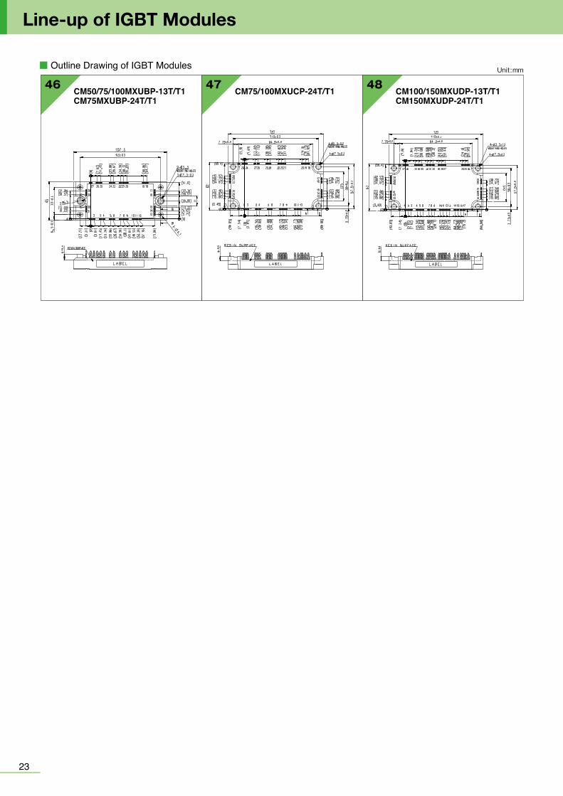
2423
Line-up of IGBT Modules
■ Outline Drawing of IGBT Modules Unit :mm
HVIGBT Modules
46 47 48CM50/75/100MXUBP-13T/T1CM75MXUBP-24T/T1
CM75/100MXUCP-24T/T1 CM100/150MXUDP-13T/T1CM150MXUDP-24T/T1
<Main Features>・Power loss reduced by incorporating 7th-generation IGBT and RFC*1 diode・Industry-leading power*2 for increased inverter capacity・External size reduced 33% while maintaining the same voltage resistance
and rated current as conventional products,*3 contributing to inverter downsizing
・Optimal package internal structure realizes improved heat dissipation, humidity resistance and flame retardance, increasing product life*1 RFC : Relaxed field of cathode*2 3.3kV - 6.5kV (as of Apr. 5, 2018 based on Mitsubishi Electric research)*3 Comparison of X Series CM1200HC-66X and H Series CM1200HC-66H
<Main Features>・ Power loss reduced by incorporating 7th-generation IGBT and RFC *1 diode・ Industry's highest 3.3kV/600A Si module power density of 8.57A/cm2 *4
contributes to increased power output and efficiency・Terminal layout optimized for easy paralleling and flexible inverter
configurations and capacities・New package structure offers extra reliability
*4 As of Apr. 5, 2018, based on Mitsubishi Electric research
■ Positioning from conventional series
H Series(CM1200HC-66H)
X Series(CM1800HC-66X)
X Series(CM1200HC-66X)
X Series B Type(CM1200HCB-66X)
1.5 times rated current
Compatible external shape
2/3 size
For smaller inverterFor smaller inverter For quicker designFor quicker design
For larger output powerFor larger output power
■ Various current ratings for optimal system designInverter capacities
500A 1000A 1500A 2000A 2500A
450A 600A
900A 1200A
1350A 1800A
1800A 2400A
450A/3.3kV product parallel connection600A/3.3kV product parallel connection
Two 450A and 600A products added to the LV100 3.3kV product lineup combined with other parallel products in answer to the need of inverters with various capacities
1 parallel
2 parallel
3 parallel
4 parallel
New Products
1.7kV 3.3kV 4.5kV 6.6kVstd Type
X Series HVIGBT Modules std type
Existing compatible package: Standard type Contributes to smaller, higher-capacity inverter systems by expanding lineup
■ Product lineup
1200A1600A2400A
1200A 900A1000A 600A
2400A3600A
1200A1800A
900A1350A1500A
600A900A1000A
X Series HVIGBT Modules dual type
New common frame package: dual type Class-leading current density contributes to increased power output in inverter systems
■ Product lineup
■ Internal circuit diagram
■ Internal circuit diagram
C type/G type(130mm×140mm)
C type/G type(190mm×140mm)
E4 type(190mm×140mm)
LV100 HV100
LV100 1.7kV
1000A
1200A
3.3kV
450A
600A
HV100 4.5kV
350A
450A
3.3kV
450A
600A
6.6kV
225A
300A
dual type
std type

2625
Line-up of HVIGBT Modules
■Series Matrix of HVIGBT/HVIPM(No.: Number of Outline Drawing, see page 29 to 31)
1700V 2500V 3300V
X-Series S-SeriesN-Series H-Series H-Series X-Series R-Series H-Series
Connection
★★: Under Development ★: New Product
CM450DC-66X★★CM450DG-66X★★
D2D2
CG
2021450A
CM600DY-34HCM600E2Y-34H
D1E2
BB
0101
CM600DC-66X★★CM600DG-66X★★
D2D2
CG
2021600A
CM1000DC-34X★★ D2 C 20 CM1000HC-66RCM1000E4C-66R
HE4
CC
08101000A
CM1500HC-66RCM1500HG-66R
HH
CG
17191500A
CM1600HC-34H H C 02CM1600HC-34X★★ H C 161600A
CM1800HC-34H H C 06 CM1800HC-66X★CM1800HG-66X★★
HH
CG
1718
CM1800HC-34NCM1800HCB-34N
HH
CC
05061800A
CM2400HC-34H H C 06CM2400HC-34NCM2400HCB-34N
HH
CC
0506
CM2400HC-34X★★CM2400HCB-34X★★
HH
CC
16172400A
CM3600HC-34X★★ H C 173600A
IC(A)
VCES(V)
CM400HG-66HCM400DY-66H
HD1
GB
0715400A CM400DY-50H D1 B 15
CM800DZ-34HCM800HA-34H
D1H
CB
01ー
CM800HC-66HCM800E4C-66HCM800E6C-66H
HE4E2
CCC
030606
800A CM800DZB-34N D1 C 01 CM800HB-50H H B 03
CM1200HC-34H H C 02CM1200DC-34X★★CM1200E4C-34X★★
D2E4
CC
2016
CM1200HC-66X★★CM1200HCB-66X★★CM1200E4C-66X★★
HHE4
CCC
161717
CM1200HG-66HCM1200HC-66HPM1200HCE330-1
HHH
CCB
090614
CM1200HCB-34NCM1200DC-34NCM1200E4C-34NCM1200DC-34S
HD1E4D1
CCCC
03040504
1200A CM1200HC-50H H C 06
■Series Matrix of HVIGBT/HVIPM(No.: Number of Outline Drawing, see page 29 to 31)
4500V 6500V
X-Series R-Series H-Series X-Series R-Series H-Series
★★: Under Development ★: New Product
IC(A)
VCES(V)
350A CM350DG-90X★★ D2 G 21
225A CM225DG-130X★★ D2 G 21
300A CM300DG-130X★★ D2 G 21
750A CM750HG-130R H G 11
200A CM200HG-130H H G 7
450A CM450DG-90X★★ D2 G 21
1000A CM1000HG-130XA★ H G 19CM1000HG-90X★★ H G 18
1350A CM1350HC-90X★★CM1350HG-90X★★
HH
CG
1719
1500A CM1500HC-90XA★CM1500HG-90X★★
HH
CG
1719
900A CM900HG-130X★★ H G 19CM900HC-90X★★CM900HG-90X★★CM900HGB-90X★★CM900E4G-90X★★
HHHE4
CGGC
16181919
CM900HG-90HCM900HC-90H
HH
GC
1309
800A CM800HC-90RCM800HG-90R
HH
CG
0813
1200ACM1200HC-90RCM1200HC-90RACM1200HG-90R
HHH
CCG
101011
600A CM600HG-90H H G 12 CM600HG-130H H G 11CM600HG-130X★★CM600HGB-130X★★CM600E4G-130X
HHE4
GGG
181919
400ACM400HG-130HCM400E2G-130HCM400E4G-130H
HE2E4
GGG
120909
Connection
H E4 D1 D2E2/E6 H E4E2/E6 D2
[Type]B:Cu base plate 6kV IsolationC:AlSiC base plate 6kV IsolationG:AlSiC base plate 10kV Isolation
[Type]B:Cu base plate 6kV IsolationC:AlSiC base plate 6kV IsolationG:AlSiC base plate 10kV Isolation
Connection No.TypeConnection No.TypeConnection No.TypeConnection No.TypeConnection No.TypeConnection No.TypeConnection No.TypeConnection No.Type Connection No.Type Connection No.Type Connection No.Type Connection No.Type Connection No.Type
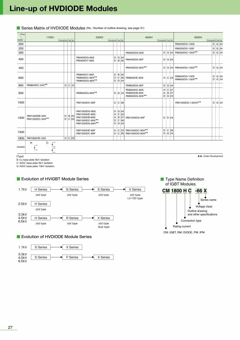
2827
■ Outline Drawing of HVIGBT Modules
Line-up of HVDIODE Modules
09 CM1200HG-66HCM900HG-90HCM400E2G/E4G-130HCM600HG-130H
07 08
02
04
03
05
01
06
CM1000HC-66RCM800HC-90R
CM400HG-66HCM200HG-130H
CM1200,1600HC-34HCM600DY-34HCM600E2Y-34HCM800DZ-34H CM800DZB-34N
CM1200HCB-34NCM800HB-50H,-66HCM800HC-66H
CM1800,2400HCB-34NCM1800,2400HC-34HCM1200HB/HC-50H,-66HCM800E4C/E6C-66HCM900HC-90H
CM1200E4C-34N CM1800,2400HC-34N
CM1200DB/DC-34NCM1200DC-34S
6
5
4
3
2
1
61.2±0.5 61.2±0.512±0.3
6-M8 NUTS
17±
0.19±
0.1
124±
0.25
44±
0.3
190±0.5
57±0.25 57±0.2557±0.25
140±
0.5
8-φ 7MOUNTING HOLES
3-M4 NUTS 14±0.3 59.2±0.5
5±0.
15
SCREWING DEPTHMIN. 7.7
SCREWING DEPTHMIN. 16.5
48+1
.0 0
130
3020
140
4-M8 NUTS
6-φ7 MOUNTING HOLES
11457±0.25
55.253
11.85
5 38
57±0.25
124±
0.25
5-M4 NUTS
57
1640 44
18
LABEL
130
140
4-M8 NUTS
6-φ7MOUNTING HOLES
11457±0.25
61.518
5 38
57±0.25
124±
0.25
3020
16.5 2.518.5
3-M4 NUTS
LABEL
130
40 140
4-M8 NUTS
6-φ7MOUNTING HOLES
11457±0.25 57±0.25
124±
0.25
3-M4 NUTS10.65
48.861.5
10.35
18
5 38
20
LABEL
1906-M8 NUTS
8-φ7MOUNTING HOLES
17157±0.25 57±0.25 57±0.25
61.5 61.513
5 3840
20
140
124±
0.25
3-M4 NUTS 41.2579.420.25
LABEL11.85±0.2
20±
0.1
4 2
3 1
130±0.557±0.25 57±0.25
140±
0.5
124±
0.25
30±
0.2
55.2±0.3
6-φ7 MOUNTING HOLES
4-M8 NUTS
6-M4 NUTS
53±0.2 57±0.240±0.2 44±0.2
5±0.
2
SCREWING DEPTHMIN. 16.5
SCREWING DEPTHMIN. 7.7
38+1 -0
4 2
3 1
20±
0.1
140±
0.5
124±
0.25
18±0.2
4-M8 NUTS
6-φ7 MOUNTING HOLES
3-M4 NUTS
130±0.557±0.25 57±0.25
40±
0.2
61.5±0.3
10.35±0.210.65±0.2
48.8±0.2
5±0.
2
SCREWING DEPTHMIN. 16.5
SCREWING DEPTHMIN. 7.7
38+1 -0
10.65±0.3 10.35±0.3
48.8±0.3
18±0.3
61.5±0.3
28±
0.5
5±0.
2
9±0.
2
40±
0.3
57±0.25 57±0.25
130±0.5
124±
0.25
140±
0.5
SCREWING DEPTHMIN. 16.5
6-φ7 MOUNTING HOLES
SCREWING DEPTHMIN. 7.7
4-M8 NUTS
3-M4 NUTS
38+1 0
20+0
.1-0
.2
1
2
3
4
17±
0.1
140±
0.5
124±
0.25
44±
0.3
73±0.557±0.25
2
1
16.2±0.3
2-M8 NUTS
4-φ 7 MOUNTING HOLES
28.7
36
521.6±0.3
5.8
5 ±0.
15
36.2
SCREWING DEPTHMIN. 16.5
SCREWING DEPTHMIN. 4
48+1
.0 0
18±0.216±0.2
12.9±0.3
Unit :mm
CM: IGBT, RM: DIODE, PM: IPM
Rating current
Connection type
Outline drawingand other specifications
Voltage class
Series name
Type Name Definition of IGBT Modules
CM 1800 H C -66 X
■ Series Matrix of HVDIODE Modules (No.: Number of outline drawing, see page 31)
CD 22RM800DC-34X★★
GD 24RM900DG-66X★★
H D
RM1200DB-34SRM1200DC-34X★★
RM1800HE-34S
BC
C
DD
H
2222
23
200250300
400
450
600
900
1000
1200
1500
1800
1700V 3300V 4500V 6500VIF(A)
VPRM
Connection
★★: Under Development[Type]B:Cu base plate 6kV IsolationC:AlSiC base plate 6kV IsolationG:AlSiC base plate 10kV Isolation
RM200DG-130S
RM250DG-130F
RM600DG-130SRM600DG-130X★★
G
G
GG
D
D
DD
24
24
2424
RM1000DG-130XA★★ GD
800
RM600HE-90S
RM1200DG-90F
RM900HC-90SRM900DB-90SRM900DG-90X★★
RM400DG-90F
RM300DG-90S
C
CBG
G
H
HDD
D
23
24
GD 24
RM450DG-90X★★ GD 24
272724
RM800DG-90F GD 24
DD 24
24
RM400DG-66SRM400DY-66S
RM600DY-66SRM600DC-66X★★
RM600DG-66X★★
RM1500HE-66FRM1500DC-66F
GB
BCG
CC
DD
DDD
HD
2425
252624
RM1000DC-66F CD 26
2326
RM1200DG-66SRM1200HE-66SRM1200DB-66SRM1200DC-66X★★
RM1200DG-66X★★
GCBCG
DHDDD
2423272624
GD 24RM450DG-130X★★
CG
DD
2624
RM1500DC-90X★★
RM1500DG-90X★★
Connection No.Type Connection No.Type Connection No.Type Connection No.Type
RM300DG-130X★★ GD 24
■ Evolution of HVIGBT Module Series
H Series
std type
N Series
std type
S Series
std type
X Series
std typeLV100 type
1.7kV
H Series
std type
R Series
std type
X Series
std typedual type
3.3kV4.5kV6.5kV
H Series
std type
2.5kV
■ Evolution of HVDIODE Module Series
S Series X Series1.7kV
S Series F Series X Series3.3kV4.5kV6.5kV

2827
■ Outline Drawing of HVIGBT Modules
Line-up of HVDIODE Modules
09 CM1200HG-66HCM900HG-90HCM400E2G/E4G-130HCM600HG-130H
07 08
02
04
03
05
01
06
CM1000HC-66RCM800HC-90R
CM400HG-66HCM200HG-130H
CM1200,1600HC-34HCM600DY-34HCM600E2Y-34HCM800DZ-34H CM800DZB-34N
CM1200HCB-34NCM800HB-50H,-66HCM800HC-66H
CM1800,2400HCB-34NCM1800,2400HC-34HCM1200HB/HC-50H,-66HCM800E4C/E6C-66HCM900HC-90H
CM1200E4C-34N CM1800,2400HC-34N
CM1200DB/DC-34NCM1200DC-34S
6
5
4
3
2
1
61.2±0.5 61.2±0.512±0.3
6-M8 NUTS
17±
0.19±
0.1
124±
0.25
44±
0.3
190±0.5
57±0.25 57±0.2557±0.25
140±
0.5
8-φ 7MOUNTING HOLES
3-M4 NUTS 14±0.3 59.2±0.5
5±0.
15
SCREWING DEPTHMIN. 7.7
SCREWING DEPTHMIN. 16.5
48+1
.0 0
13030
20
140
4-M8 NUTS
6-φ7 MOUNTING HOLES
11457±0.25
55.253
11.85
5 3857±0.25
124±
0.25
5-M4 NUTS
57
1640 44
18
LABEL
130
140
4-M8 NUTS
6-φ7MOUNTING HOLES
11457±0.25
61.518
5 38
57±0.25
124±
0.25
3020
16.5 2.518.5
3-M4 NUTS
LABEL
130
40 140
4-M8 NUTS
6-φ7MOUNTING HOLES
11457±0.25 57±0.25
124±
0.25
3-M4 NUTS10.65
48.861.5
10.35
18
5 38
20
LABEL
1906-M8 NUTS
8-φ7MOUNTING HOLES
17157±0.25 57±0.25 57±0.25
61.5 61.513
5 3840
20
140
124±
0.25
3-M4 NUTS 41.2579.420.25
LABEL11.85±0.2
20±
0.1
4 2
3 1
130±0.557±0.25 57±0.25
140±
0.5
124±
0.25
30±
0.2
55.2±0.3
6-φ7 MOUNTING HOLES
4-M8 NUTS
6-M4 NUTS
53±0.2 57±0.240±0.2 44±0.2
5±0.
2
SCREWING DEPTHMIN. 16.5
SCREWING DEPTHMIN. 7.7
38+1 -0
4 2
3 1
20±
0.1
140±
0.5
124±
0.25
18±0.2
4-M8 NUTS
6-φ7 MOUNTING HOLES
3-M4 NUTS
130±0.557±0.25 57±0.25
40±
0.2
61.5±0.3
10.35±0.210.65±0.2
48.8±0.2
5±0.
2
SCREWING DEPTHMIN. 16.5
SCREWING DEPTHMIN. 7.7
38+1 -0
10.65±0.3 10.35±0.3
48.8±0.3
18±0.3
61.5±0.3
28±
0.5
5±0.
2
9±0.
2
40±
0.3
57±0.25 57±0.25
130±0.5
124±
0.25
140±
0.5
SCREWING DEPTHMIN. 16.5
6-φ7 MOUNTING HOLES
SCREWING DEPTHMIN. 7.7
4-M8 NUTS
3-M4 NUTS
38+1 0
20+0
.1-0
.2
1
2
3
4
17±
0.1
140±
0.5
124±
0.25
44±
0.3
73±0.557±0.25
2
1
16.2±0.3
2-M8 NUTS
4-φ 7 MOUNTING HOLES
28.7
36
521.6±0.3
5.8
5 ±0.
15
36.2
SCREWING DEPTHMIN. 16.5
SCREWING DEPTHMIN. 4
48+1
.0 0
18±0.216±0.2
12.9±0.3
Unit :mm
CM: IGBT, RM: DIODE, PM: IPM
Rating current
Connection type
Outline drawingand other specifications
Voltage class
Series name
Type Name Definition of IGBT Modules
CM 1800 H C -66 X
■ Series Matrix of HVDIODE Modules (No.: Number of outline drawing, see page 31)
CD 22RM800DC-34X★★
GD 24RM900DG-66X★★
H D
RM1200DB-34SRM1200DC-34X★★
RM1800HE-34S
BC
C
DD
H
2222
23
200250300
400
450
600
900
1000
1200
1500
1800
1700V 3300V 4500V 6500VIF(A)
VPRM
Connection
★★: Under Development[Type]B:Cu base plate 6kV IsolationC:AlSiC base plate 6kV IsolationG:AlSiC base plate 10kV Isolation
RM200DG-130S
RM250DG-130F
RM600DG-130SRM600DG-130X★★
G
G
GG
D
D
DD
24
24
2424
RM1000DG-130XA★★ GD
800
RM600HE-90S
RM1200DG-90F
RM900HC-90SRM900DB-90SRM900DG-90X★★
RM400DG-90F
RM300DG-90S
C
CBG
G
H
HDD
D
23
24
GD 24
RM450DG-90X★★ GD 24
272724
RM800DG-90F GD 24
DD 24
24
RM400DG-66SRM400DY-66S
RM600DY-66SRM600DC-66X★★
RM600DG-66X★★
RM1500HE-66FRM1500DC-66F
GB
BCG
CC
DD
DDD
HD
2425
252624
RM1000DC-66F CD 26
2326
RM1200DG-66SRM1200HE-66SRM1200DB-66SRM1200DC-66X★★
RM1200DG-66X★★
GCBCG
DHDDD
2423272624
GD 24RM450DG-130X★★
CG
DD
2624
RM1500DC-90X★★
RM1500DG-90X★★
Connection No.Type Connection No.Type Connection No.Type Connection No.Type
RM300DG-130X★★ GD 24
■ Evolution of HVIGBT Module Series
H Series
std type
N Series
std type
S Series
std type
X Series
std typeLV100 type
1.7kV
H Series
std type
R Series
std type
X Series
std typedual type
3.3kV4.5kV6.5kV
H Series
std type
2.5kV
■ Evolution of HVDIODE Module Series
S Series X Series1.7kV
S Series F Series X Series3.3kV4.5kV6.5kV

3029
Line-up of HVIGBT Modules
■ Outline Drawing of HVIGBT Modules Unit :mm
11
13 14 PM1200HCE330-1
17(16.5)
18.3
15.8
5
(14)
(15)
(15)
61.5±0.3
41
61.5±0.3
124±
0.3
140±
0.3
6-M8NUTS13 Screwing depth16.5mm
(Electrode thickness 1.0mm)
8-ø6.5 MOUNTING HOLES
2-M3 Screwing
38
9.3
+1.0
0
2.6
2311
190±0.357±0.3
40
4557±0.357±0.3
10 CM1000E4C-66RCM1500HC-66RCM1200HC-90RCM1200HC-90RA
CM800HG-90R
16 CM1200E4C-34XCM1600HC-34XCM2400HC-34XCM1200HC-66XCM900HC-90X
CM1500HG-66RCM1200HG-90RCM750HG-130R
12 CM600HG-90HCM400HG-130H
28±
0.5
5±0.
3
20.25±0.341.25±0.3
79.4±0.3
124±
0.25
140±
0.5
61.5±0.361.5±0.3
57±0.25 57±0.25 57±0.25
40±
0.3
13±0.3
190±0.5
SCREWING DEPTHMIN. 16.5
SCREWING DEPTHMIN. 7.7
6-M8 NUTS
3-M4 NUTS
8-φ7 MOUNTING HOLES
38+1 0
1
2
3
4
5
6
4
3
2
1
61.2±0.5
16.5±0.3
4-M8 NUTS
17±
0.1
9±0.
1
124±
0.25
44±
0.3
130±0.5
57±0.25 57±0.25
140±
0.5
6-φ7 MOUNTING HOLES
3-M4 NUTS 28.5±0.5
42.5±0.3 30.7±0.5
5±0.
15
SCREWING DEPTHMIN. 7.7
SCREWING DEPTHMIN. 16.5
48+1
.0 0
38+1
.0 0
Unit :mm
14 0.3
380.5
50.2
6-M8 NUTS
3-M4 NUTS 8-φ7MOUNTING HOLES
SCREWING DEPTHMIN 16.5SCREWING DEPTHMIN 7.7
4-M8 NUTS
3-M4 NUTS 6-φ7 MOUNTING HOLES
SCREWING DEPTHMIN 7.7 SCREWING DEPTHMIN 16.5
380.
5
14 0.3
440.
3
15 CM400DY-50H/66H
17 CM2400HCB-34X, CM3600HC-34XCM1200E4C-66X, CM1200HCB-66XCM1800HC-66XCM1350HC-90XCM1500HC-90XA
18 CM900HG-90XCM1000HG-90XCM600HG-130X
130114
2040
24.536.37.2
53.6
61.5
385
0+2
280+2
18
48.8
140
E1
E2
E1E2(C1)
G1
G2
C1
C2
CM
C2
57±0.25
124±
0.25
6-φ 6 MOUNTING HOLES
SCREWINGDEPTHMIN 11.7
SCREWINGDEPTHMIN 7.7
4-M 8 NUTS
5-M 4 NUTS
57±0.25
57±0.25 57±0.25
10.35±0.310.65±0.3
61.5±0.3
18±0.3
48.8±0.3
40±
0.3
124±
0.25
9±0.
2
28±
0.5
5±0.
214
0±0.
5
130±0.5
4-M8 NUTS
SCREWINGDEPTHMIN 7.7
SCREWINGDEPTHMIN 16.5
3-M4 NUTS
20-0
.2+0
.1
38-0+1
6-φ 7MOUNTING HOLES
140±
0.5
124±
0.25
9±0.
25±
0.2
28±
0.5
40±
0.3
57±0.25 57±0.25
20.25±0.3
13±0.3
41.25±0.3
79.4±0.3
61.5±0.3 61.5±0.3
57±0.25
190±0.5 6-M8 NUTS
SCREWINGDEPTHMIN 16.5
3-M4 NUTS
20-0
.2+0
.138
0+1
8-φ 7MOUNTING HOLES
SCREWINGDEPTHMIN 7.7
48-0+1
17-0
.2+0
.1
130±0.5
57±0.25 57±0.25
140±
0.5
44±
0.3
9±0.
2
14±0.3 28.5±0.3
59.2±0.3
61.2±0.316.5±0.3
124±
0.25
38±
0.5
5±0.
2
6-φ 7MOUNTING HOLES
SCREWINGDEPTHMIN 16.5
SCREWINGDEPTHMIN 7.7
3-M4 NUTS
4-M8 NUTS
2019 CM1800HG-66XCM900HGB-90X, CM900E4G-90XCM1350HG-90X, CM1500HG-90XCM600HGB-130X, CM600E4G-130XCM900HG-130X, CM1000HG-130XA
CM1000DC-34XCM1200DC-34XCM450DC-66XCM600DC-66X
21 CM450DG-66X, CM600DG-66XCM350DG-90X, CM450DG-90XCM225DG-130X, CM300DG-130X
6-M8 NUTS
3-M4 NUTS
190±0.5
14±0.3
12±0.3
59.2±0.3
61.2±0.361.2±0.3
57±0.25 57±0.25 57±0.25
44±
0.3
38±
0.5
5±0.
2
17-0
.2+0
.148
-0+1
SCREWINGDEPTHMIN 16.5
SCREWINGDEPTHMIN 7.7
8-φ 7MOUNTINGHOLES
140±
0.5
124±
0.25
4-φ6.5 MOUNTING HOLES
8-M3 NUTS
7-M8 NUTS
86±0.25
82±0.3
46±0.3
99.5±0.5
46±0.3
144±
0.5
140±
0.5
127±
0.25
25.2
5±0.
3
4.5±
0.3
29.5
±0.
3
122.
5±0.
3 69±
0.3
53.5
±0.
3
22.5
±0.
3
13±
0.3
9.5±
0.3
44±
0.3
53.5
±0.
3
99.5±0.5
(18)
(7.2)
44±0.3
18 +0.1-0.2
18 +0.1-0.2
4-M8 NUTS
6-M3 NUTS
4-φ8.5 MOUMTING HOLES
86±0.25
67±0.3
44±0.3
122.
5±0.
3
144±
0.5
140±
0.5
127±
0.25
59±
0.3
49.5
±0.
3
84.2
±0.
3
59±
0.3
31.5
±0.
3
9.5±
0.3
(4.5)
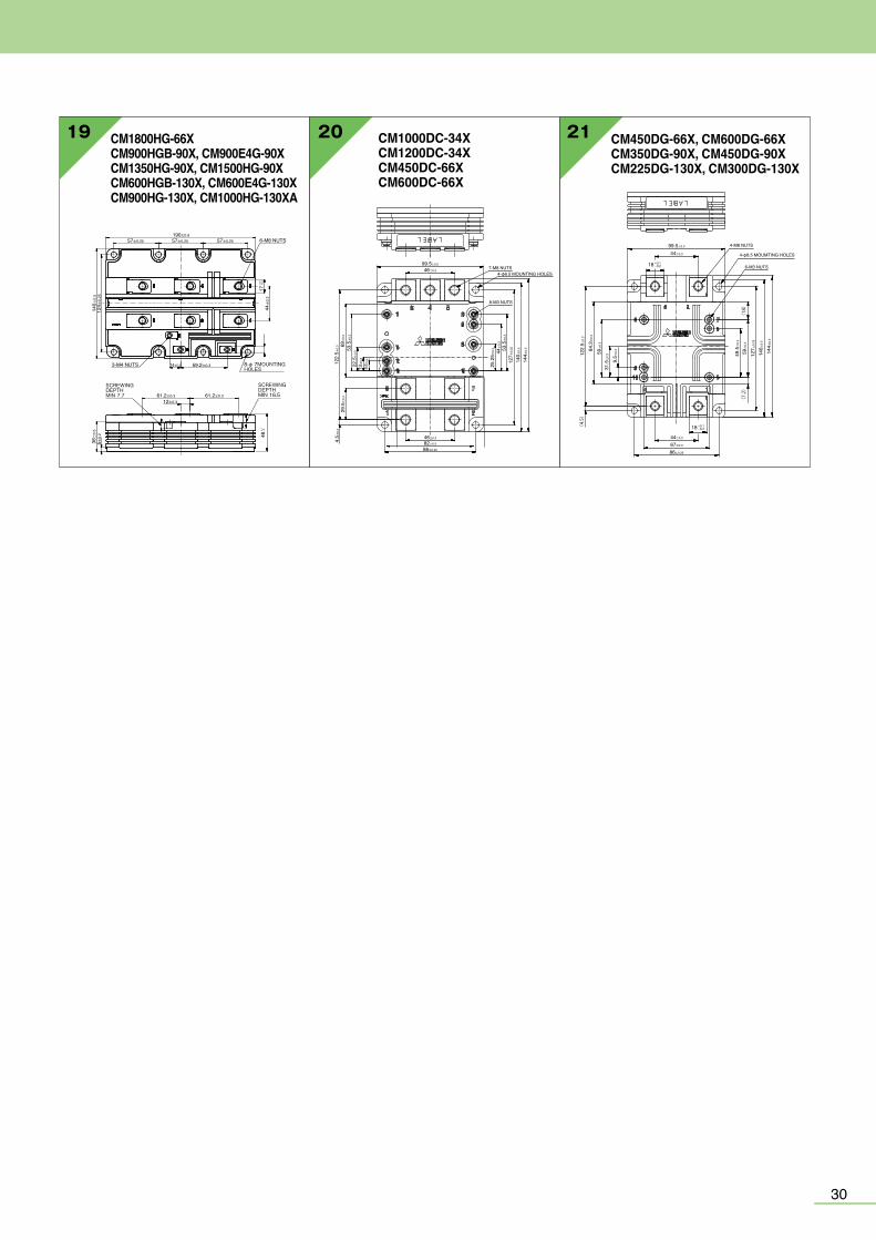

3231
Line-up of HVDIODE Modules Line-up of MOSFET Modules
■ Outline Drawing of HVDIODE Modules Unit :mm
23
2625RM400,600DY-66S
RM1800HE-34SRM1200HE-66S RM600HE-90SRM1500HE-66F
27 RM1200DB-66SRM900DB/HC-90S
22 24
130
140
4 - M8 NUTS
LABEL
6-φ7 MOUNTING HOLES
11457±0.25
61.518
5 38
57±0.25
124±
0.25
4020
4-φ6.5 MOUNTING HOLES
130
>PPS< 114±
0.3
74±0.3
38+1
.0 0
29.7 9.
361
.5
40
90
4-M8 NUTS
SCREWING DEPTHMIN. 16.5
38+1 –0
4-M8 NUTS
CM
40
57±0.2557±0.25
140
130
1861.5
124±
0.25
205
6-φ7 MOUNTING HOLES
4
3
2
1
55.2±0.311.85±0.2
4-M8 NUTS
20±
0.1
130±0.5
57±0.25 57±0.2514
0±0.
5
124±
0.25
30±
0.2
6-φ7 MOUNTING HOLES
5±0.
2
38+1
.0 0
SCREWING DEPTHMIN. 16.5
>PET+PBT<
5±0.
2
40±
0.3
57±0.25 57±0.25
130±0.5
124±
0.25
140±
0.5
18±0.3
61.5±0.3
4-M8 NUTS
SCREWING DEPTHMIN. 16.5
6-φ7 MOUNTING HOLES
38+1 0
20+0
.1-0
.2
1
2
3
4
RM1000,1500DC-66FRM600DC-66XRM1200DC-66XRM1500DC-90X
RM1200DB-34SRM800DC-34XRM1200DC-34X
RM400/1200DG-66SRM300DG-90SRM200/600DG-130SRM400/800/1200DG-90FRM250DG-130FRM600/900/1200DG-66XRM450/900/1500DG-90XRM300/450/600DG-130XRM1000DG-130XA
4
3
2
1
61.2±0.516.5±0.3
4-M8 NUTS
17±
0.1
124±
0.25
44±
0.3
130±0.557±0.25 57±0.25
140±
0.5
6-φ7 MOUNTING HOLES
5±0.
15
48+1
.0 0
SCREWING DEPTHMIN. 16.5
100200300
ID (A)
VDSS
Connection
FM200TU-07A, -2A, -3AFM400TU-07A, -2A, -3AFM600TU-07A, -2A, -3A
11.5
9.1
11097
83 8.812 12.916.5 16 1632
1 1314
7
612
6.5
11.5
35 26 25
16.5 32 32
6.520
44
6738
90 80
R6.5
ø6.5
ø6.5ø6.5
Unit :mm
T
RoHS directive (2011/65/EU, (EU)2015/863) compliant
Outline Drawing of MOSFET Modules
Series Matrix of MOSFET Modules
FM200TU-07AFM400TU-07AFM600TU-07A
75V
TTT
Connection
FM200TU-2AFM400TU-2AFM600TU-2A
100V
TTT
Connection
FM200TU-3AFM400TU-3AFM600TU-3A
150V
TTT
Connection

3231
Line-up of HVDIODE Modules Line-up of MOSFET Modules
■ Outline Drawing of HVDIODE Modules Unit :mm
23
2625RM400,600DY-66S
RM1800HE-34SRM1200HE-66S RM600HE-90SRM1500HE-66F
27 RM1200DB-66SRM900DB/HC-90S
22 24
130
140
4 - M8 NUTS
LABEL
6-φ7 MOUNTING HOLES
11457±0.25
61.518
5 38
57±0.25
124±
0.25
4020
4-φ6.5 MOUNTING HOLES
130
>PPS< 114±
0.3
74±0.3
38+1
.0 0
29.7 9.
361
.5
40
90
4-M8 NUTS
SCREWING DEPTHMIN. 16.5
38+1 –0
4-M8 NUTS
CM
40
57±0.2557±0.25
140
130
1861.5
124±
0.25
205
6-φ7 MOUNTING HOLES
4
3
2
1
55.2±0.311.85±0.2
4-M8 NUTS
20±
0.1
130±0.5
57±0.25 57±0.25
140±
0.5
124±
0.25
30±
0.2
6-φ7 MOUNTING HOLES
5±0.
2
38+1
.0 0
SCREWING DEPTHMIN. 16.5
>PET+PBT<
5±0.
2
40±
0.3
57±0.25 57±0.25
130±0.5
124±
0.25
140±
0.5
18±0.3
61.5±0.3
4-M8 NUTS
SCREWING DEPTHMIN. 16.5
6-φ7 MOUNTING HOLES
38+1 0
20+0
.1-0
.2
1
2
3
4
RM1000,1500DC-66FRM600DC-66XRM1200DC-66XRM1500DC-90X
RM1200DB-34SRM800DC-34XRM1200DC-34X
RM400/1200DG-66SRM300DG-90SRM200/600DG-130SRM400/800/1200DG-90FRM250DG-130FRM600/900/1200DG-66XRM450/900/1500DG-90XRM300/450/600DG-130XRM1000DG-130XA
4
3
2
1
61.2±0.516.5±0.3
4-M8 NUTS
17±
0.1
124±
0.25
44±
0.3
130±0.557±0.25 57±0.25
140±
0.5
6-φ7 MOUNTING HOLES
5±0.
15
48+1
.0 0
SCREWING DEPTHMIN. 16.5
100200300
ID (A)
VDSS
Connection
FM200TU-07A, -2A, -3AFM400TU-07A, -2A, -3AFM600TU-07A, -2A, -3A
11.5
9.1
11097
83 8.812 12.916.5 16 1632
1 1314
7
612
6.5
11.5
35 26 25
16.5 32 32
6.520
44
6738
90 80
R6.5
ø6.5
ø6.5ø6.5
Unit :mm
T
RoHS directive (2011/65/EU, (EU)2015/863) compliant
Outline Drawing of MOSFET Modules
Series Matrix of MOSFET Modules
FM200TU-07AFM400TU-07AFM600TU-07A
75V
TTT
Connection
FM200TU-2AFM400TU-2AFM600TU-2A
100V
TTT
Connection
FM200TU-3AFM400TU-3AFM600TU-3A
150V
TTT
Connection
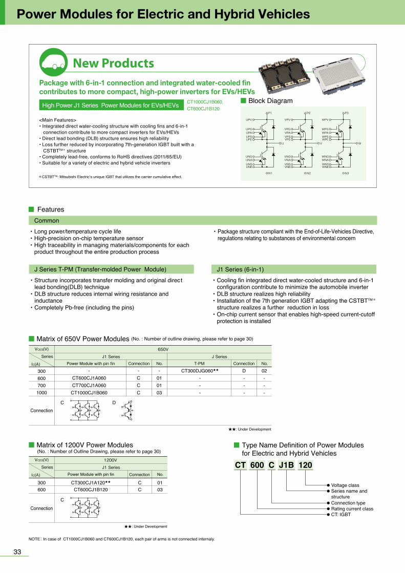
UPV
UPGUPAUPSUPE
VPV
VPGVPAVPSVPE
WPV
WPGWPAWPSWPE
UNGUNAUNSUNE
U
VNGVNAVNSVNE
V
WNGWNAWNSWNE
W
P1
N1
P2
N2
P3
N3
■ Matrix of 650V Power Modules (No. : Number of outline drawing, please refer to page 30)
New ProductsPackage with 6-in-1 connection and integrated water-cooled fin contributes to more compact, high-power inverters for EVs/HEVs
3433
Power Modules for Electric and Hybrid Vehicles
*CSTBTTM: Mitsubishi Electric’s unique IGBT that utilizes the carrier cumulative effect.
■ Matrix of 1200V Power Modules (No. : Number of Outline Drawing, please refer to page 30)
Type Name Definition of Power Modules for Electric and Hybrid Vehicles
Features
・Long power/temperature cycle life・High-precision on-chip temperature sensor・High traceability in managing materials/components for each
product throughout the entire production process
Common・Package structure compliant with the End-of-Life-Vehicles Directive,
regulations relating to substances of environmental concern
・Structure incorporates transfer molding and original direct lead bonding(DLB) technique
・DLB structure reduces internal wiring resistance and inductance
・Completely Pb-free (including the pins)
J Series T-PM (Transfer-molded Power Module)・Cooling fin integrated direct water-cooled structure and 6-in-1
configuration contribute to minimize the automobile inverter・DLB structure realizes high reliability・Installation of the 7th generation IGBT adapting the CSTBTTM*
structure realizes a further reduction in loss・On-chip current sensor that enables high-speed current-cutoff
protection is installed
J1 Series (6-in-1)
02 CT300DJG06001
■ Outline Drawing of Power Modules for Electric and Hybrid Vehicles
03 CT1000CJ1B060CT600CJ1B120
Unit :mm
<Main Features>• Integrated direct water-cooling structure with cooling fins and 6-in-1 connection contribute to more compact inverters for EVs/HEVs• Direct lead bonding (DLB) structure ensures high reliability• Loss further reduced by incorporating 7th-generation IGBT built with a CSTBTTM* structure• Completely lead-free, conforms to RoHS directives (2011/65/EU)• Suitable for a variety of electric and hybrid vehicle inverters
CT1000CJ1B060,CT600CJ1B120High Power J1 Series Power Modules for EVs/HEVs 23
36.8
13.2
53.2
83.2
77.2
6
16
38.557.5
68.7
2.5
12.4 0.3±
26.6
0.3
±
7.3
0.2
±
13.7
0.2
±
23.2
0.3
±
43.2
0.3
±
66.4
0.1
±
73.7
0.2
±
79.4
80.
2±
2.54 0.2±
6.75 0.3±9 0.2±
17.45 0.2±
32.83 0.2±
48 0.3±
60.83 0.2±
86.2 0.2±86.2 0.1±
13.0
80.
2±
15.2
0.2
±
51.2
0.2
±
66.4
0.1
±
86.2 0.1±
62.33
A
UNAUNSUNEUNG
UPG
PPV
N
U
V
W
UPEUPSUPAVPGVPEVPSVPA
WPGWPEWPSWPA
VNAVNSVNEVNG
WNAWNSWNEWNG
0.2±
40.33 0.2±
18.45 0.2±
for self tapping screw
4xφ5.5
4xφ74xφ9
24-□0.64□1
12.5
66.4
18.9
3.5mm x 5mm
88.792.25xM5 8Max.
78.7 0.3±
φ5.4
3-φ6
2-φ2.5
42.6
69.5
49.6
12
6.33
10.1
6
125.
08
5.08P=
2.54
12
P=2.
5444
0.2
±
7
16.7
0.5
± 0.64
6.5
2-1.
5
3.36
50.
2±
23.8 1± 23.8 1±
18.5 0.2±
170.
2± 8.
7
AP
PGPEPSPV
NSNENGNKNA
N
U
29.25 0.4±
9-□0.64
1 M MA29.25 0.4±■ Block Diagram
CT: IGBT
Voltage class
Rating current classConnection type
Series name and structure
CT 600 C J1B 120No.Connection
1200V
J1 SeriesPower Module with pin fin
Series
IC(A)
VCES(V)
★★: Under Development
No. No.Connection Connection
650V
J1 Series J SeriesPower Module with pin fin T-PM
Connection
Series
IC(A)
VCES(V)
8-φ5.58-φ12.8
48.8
16.412-M6 MAX.13MM
3.5×8MM
16.4 16.43-16
5.1
9.3
4.6
6-4.986-4.987-4.987-4.987-4.98 6-4.98
3-32 38.4
53.95
50.7553.4562.25
3-7.5
3-15
.6
3-6.
64
3-9.1
3-10.8
6-12
.7(p
=2.5
4)3-8
.5
124.
5
14.65 14.65 14.653-19.5
3-14.5
3-7 3-7
3-14.5
101.
4
163131.4
75.4
33.7
3-50
.44
48.8 48.8
39-□0.64
8-φ98-φ7
INLET OF COOLING WATER
FOR SELF TAPPING SCREWUNAUNSUNE1UNG1UNE2UNG2
VNAVNSVNE1VNG1VNE2VNG2
WNAWNSWNE1WNG1WNE2WNG2
WPG1WPE1
WPSWPA
WPG2WPE2
WPV
VPG1VPE1
VPSVPA
VPG2VPE2
VPV
UPG1UPE1
UPSUPA
UPG2UPE2
UPV
CT600CJ1A060CT700CJ1A060CT300CJ1A120
CT600CJ1B120 C600
Connection
03CT300CJ1A120★★ C300 01
C
-CT600CJ1A060CT700CJ1A060CT1000CJ1B060
-CCC
CT300DJG060★★
---
D---
02---
-010103
3006007001000
DC
★★: Under Development
NOTE: In case of CT1000CJ1B060 and CT600CJ1B120, each pair of arms is not connected internaly.
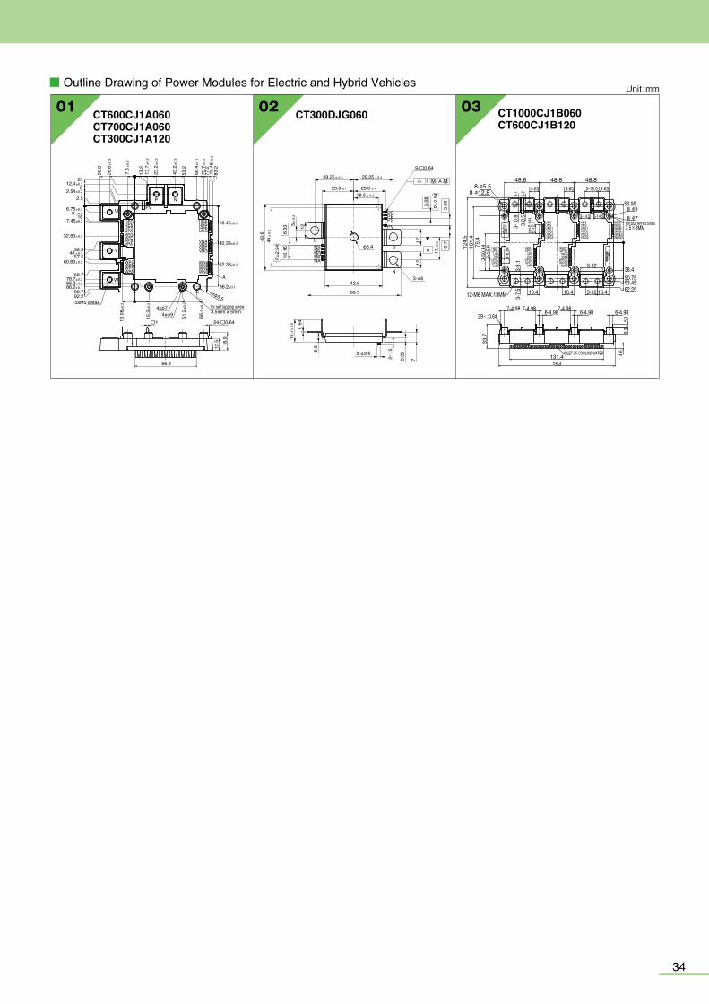
UPV
UPGUPAUPSUPE
VPV
VPGVPAVPSVPE
WPV
WPGWPAWPSWPE
UNGUNAUNSUNE
U
VNGVNAVNSVNE
V
WNGWNAWNSWNE
W
P1
N1
P2
N2
P3
N3
■ Matrix of 650V Power Modules (No. : Number of outline drawing, please refer to page 30)
New ProductsPackage with 6-in-1 connection and integrated water-cooled fin contributes to more compact, high-power inverters for EVs/HEVs
3433
Power Modules for Electric and Hybrid Vehicles
*CSTBTTM: Mitsubishi Electric’s unique IGBT that utilizes the carrier cumulative effect.
■ Matrix of 1200V Power Modules (No. : Number of Outline Drawing, please refer to page 30)
Type Name Definition of Power Modules for Electric and Hybrid Vehicles
Features
・Long power/temperature cycle life・High-precision on-chip temperature sensor・High traceability in managing materials/components for each
product throughout the entire production process
Common・Package structure compliant with the End-of-Life-Vehicles Directive,
regulations relating to substances of environmental concern
・Structure incorporates transfer molding and original direct lead bonding(DLB) technique
・DLB structure reduces internal wiring resistance and inductance
・Completely Pb-free (including the pins)
J Series T-PM (Transfer-molded Power Module)・Cooling fin integrated direct water-cooled structure and 6-in-1
configuration contribute to minimize the automobile inverter・DLB structure realizes high reliability・Installation of the 7th generation IGBT adapting the CSTBTTM*
structure realizes a further reduction in loss・On-chip current sensor that enables high-speed current-cutoff
protection is installed
J1 Series (6-in-1)
02 CT300DJG06001
■ Outline Drawing of Power Modules for Electric and Hybrid Vehicles
03 CT1000CJ1B060CT600CJ1B120
Unit :mm
<Main Features>• Integrated direct water-cooling structure with cooling fins and 6-in-1 connection contribute to more compact inverters for EVs/HEVs• Direct lead bonding (DLB) structure ensures high reliability• Loss further reduced by incorporating 7th-generation IGBT built with a CSTBTTM* structure• Completely lead-free, conforms to RoHS directives (2011/65/EU)• Suitable for a variety of electric and hybrid vehicle inverters
CT1000CJ1B060,CT600CJ1B120High Power J1 Series Power Modules for EVs/HEVs 23
36.8
13.2
53.2
83.2
77.2
6
16
38.557.5
68.7
2.5
12.4 0.3±
26.6
0.3
±
7.3
0.2
±
13.7
0.2
±
23.2
0.3
±
43.2
0.3
±
66.4
0.1
±
73.7
0.2
±
79.4
80.
2±
2.54 0.2±
6.75 0.3±9 0.2±
17.45 0.2±
32.83 0.2±
48 0.3±
60.83 0.2±
86.2 0.2±86.2 0.1±
13.0
80.
2±
15.2
0.2
±
51.2
0.2
±
66.4
0.1
±
86.2 0.1±
62.33
A
UNAUNSUNEUNG
UPG
PPV
N
U
V
W
UPEUPSUPAVPGVPEVPSVPA
WPGWPEWPSWPA
VNAVNSVNEVNG
WNAWNSWNEWNG
0.2±
40.33 0.2±
18.45 0.2±
for self tapping screw
4xφ5.5
4xφ74xφ9
24-□0.64□1
12.5
66.4
18.9
3.5mm x 5mm
88.792.25xM5 8Max.
78.7 0.3±
φ5.4
3-φ6
2-φ2.5
42.6
69.5
49.6
12
6.33
10.1
6
125.
08
5.08P=
2.54
12
P=2.
5444
0.2
±
7
16.7
0.5
± 0.64
6.5
2-1.
5
3.36
50.
2±
23.8 1± 23.8 1±
18.5 0.2±
170.
2± 8.
7
AP
PGPEPSPV
NSNENGNKNA
N
U
29.25 0.4±
9-□0.64
1 M MA29.25 0.4±■ Block Diagram
CT: IGBT
Voltage class
Rating current classConnection type
Series name and structure
CT 600 C J1B 120No.Connection
1200V
J1 SeriesPower Module with pin fin
Series
IC(A)
VCES(V)
★★: Under Development
No. No.Connection Connection
650V
J1 Series J SeriesPower Module with pin fin T-PM
Connection
Series
IC(A)
VCES(V)
8-φ5.58-φ12.8
48.8
16.412-M6 MAX.13MM
3.5×8MM
16.4 16.43-16
5.1
9.3
4.6
6-4.986-4.987-4.987-4.987-4.98 6-4.98
3-32 38.4
53.95
50.7553.4562.25
3-7.5
3-15
.6
3-6.
64
3-9.1
3-10.8
6-12
.7(p
=2.5
4)3-8
.5
124.
5
14.65 14.65 14.653-19.5
3-14.5
3-7 3-7
3-14.5
101.
4
163131.4
75.4
33.7
3-50
.44
48.8 48.8
39-□0.64
8-φ98-φ7
INLET OF COOLING WATER
FOR SELF TAPPING SCREWUNAUNSUNE1UNG1UNE2UNG2
VNAVNSVNE1VNG1VNE2VNG2
WNAWNSWNE1WNG1WNE2WNG2
WPG1WPE1
WPSWPA
WPG2WPE2
WPV
VPG1VPE1
VPSVPA
VPG2VPE2
VPV
UPG1UPE1
UPSUPA
UPG2UPE2
UPV
CT600CJ1A060CT700CJ1A060CT300CJ1A120
CT600CJ1B120 C600
Connection
03CT300CJ1A120★★ C300 01
C
-CT600CJ1A060CT700CJ1A060
CT1000CJ1B060
-CCC
CT300DJG060★★
---
D---
02---
-010103
3006007001000
DC
★★: Under Development
NOTE: In case of CT1000CJ1B060 and CT600CJ1B120, each pair of arms is not connected internaly.
H-CT575-E FU-1905 Printed in Japan <IP>
POWER MODULES
Revised publication, effective May 2019.Superseding publication of H-CT575-D Apr. 2019.
Specifications subject to change without notice.
2019
POWER MODULES
www.MitsubishiElectric.com/semiconductors/
Mitsubishi Electric Semiconductors & Devices Website
PowerModules


![ELCODIS.COM - ELECTRONIC COMPONENTS DISTRIBUTORdatasheet.elcodis.com/pdf2/73/7/730774/m63016fp.pdf · MITSUBISHI SEMICONDUCTORS M63016FP Spindle Motor AND 4CH ACTUATOR Drive IC [FEATURES]](https://img.pdfslide.net/doc/110x75/60d8ba5e32d4de45ed059731/-electronic-components-distributordatasheetelcodiscompdf2737730774m63016fppdf.jpg)