Embed Size (px)
Citation preview

INDEX
Copyright © ATSG 2008
MITSUBISHI MONTEROR/V4A51 AND V5A51
(4 Speed) (5 Speed)
AUTOMATIC TRANSMISSION SERVICE GROUP18635 S.W. 107 AVENUEMIAMI, FLORIDA 33157
(305) 670-4161
QUICK EXTERNAL IDENTIFICATION .......................................................................................................................IDENTIFICATION CODE STAMPING LOCATION ....................................................................................................4 SPEED COMPONENT APPLICATION CHART ........................................................................................................5 SPEED COMPONENT APPLICATION CHART ........................................................................................................ELECTRONIC COMPONENT DESCRIPTION .............................................................................................................SOLENOID CONNECTOR IDENTIFICATION AND RESISTANCE CHART ...........................................................4 SPEED WIRE SCHEMATIC ........................................................................................................................................4 SPEED CONNECTOR IDENTIFICATION .................................................................................................................5 SPEED WIRE SCHEMATIC ........................................................................................................................................5 SPEED CONNECTOR IDENTIFICATION .................................................................................................................DIAGNOSTIC TROUBLE CODE DESCRIPTION ........................................................................................................AIR CHECKS ....................................................................................................................................................................LINE PRESSURE TEST SPECS, PRESSURE TAP LOCATIONS, FLUID SPECIFICATION .................................TRANSMISSION DISASSEMBLY ..................................................................................................................................COMPONENT REBUILD SECTION TRANSMISSION CASE ASSEMBLY ..................................................................................................................... EXTENSION HOUSING OR 4WD ADAPTER HOUSING ................................................................................... 2WD SPEEDOMETER GEAR ASSEMBLY .......................................................................................................... OIL PUMP ASSEMBLY ........................................................................................................................................... OVERDRIVE AND REVERSE CLUTCH HOUSING ASSEMBLY ...................................................................... PLANETARY GEAR TRAIN AND LOW SPRAG ASSEMBLY ............................................................................. REVERSE SUN GEAR AND HUB ASSEMBLY .................................................................................................... CENTER SUPPORT ASSEMBLY ........................................................................................................................... REDUCTION ANNULUS AND UNDERDRIVE CLUTCH HOUSING ASSEMBLY .......................................... 2ND BRAKE CLUTCH PISTON AND RETAINER ASSEMBLY ......................................................................... REDUCTION SERVO ASSEMBLY ......................................................................................................................... DIRECT CLUTCH HOUSING ASSEMBLY ........................................................................................................... 4 SPEED OUTPUT SHAFT SUPPORT .................................................................................................................. 5 SPEED OUTPUT SHAFT SUPPORT AND DIRECT SPRAG ASSEMBLY ..................................................... DIRECT SPRAG FREEWHEEL DIRECTION ...................................................................................................... LOW SPRAG FREEWHEEL DIRECTION ............................................................................................................ REDUCTION CARRIER AND OUTPUT SHAFT ASSEMBLY ............................................................................ VALVE BODY ASSEMBLY ...................................................................................................................................... CHECK BALL LOCATIONS ....................................................................................................................................TRANSMISSION ASSEMBLY (4 SPEED) .....................................................................................................................TRANSMISSION ASSEMBLY (5 SPEED) .....................................................................................................................REDUCTION BAND ADJUSTMENT .............................................................................................................................TORQUE SPECIFICATIONS ..........................................................................................................................................THRUST BEARING IDENTIFICATION .......................................................................................................................SPECIAL SERVICE TOOLS ...........................................................................................................................................
345678
1415161719202124
4548495155626666707576788182848586889197
100112124125126

INTRODUCTIONR/V4A51 AND V5A51
AUTOMATIC TRANSMISSION SERVICE GROUP18635 S.W. 107 AVENUEMIAMI, FLORIDA 33157
(305) 670-4161 1
No part of any ATSG publication may be reproduced, stored in any retrieval system or transmitted in any form or by any means, including but not limited to electronic, mechanical, photocopying, recording or otherwise, without written permission of Automatic Transmission Service Group. This includes all text illustrations, tables and charts.
The information and part numbers contained in this booklet havebeen carefully compiled from industry sources known for their
reliability, but ATSG does not guarantee its accuracy.
Copyright © ATSG 2008
1st PrintingNovember, 2008
DALE ENGLANDFIELD SERVICE CONSULTANT
ED KRUSETECHNICAL CONSULTANT
WAYNE COLONNAPRESIDENT
PETER LUBANTECHNICAL CONSULTANT
JIM DIALTECHNICAL CONSULTANT
GREGORY LIPNICKTECHNICAL CONSULTANT
RICHARD GRAHAMTECHNICAL CONSULTANT
JON GLATSTEINTECHNICAL CONSULTANT
DAVID CHALKERTECHNICAL CONSULTANT
ROLAND ALVAREZTECHNICAL CONSULTANT
GREG CATANZAROTECHNICAL CONSULTANT
GERALD CAMPBELLTECHNICAL CONSULTANT
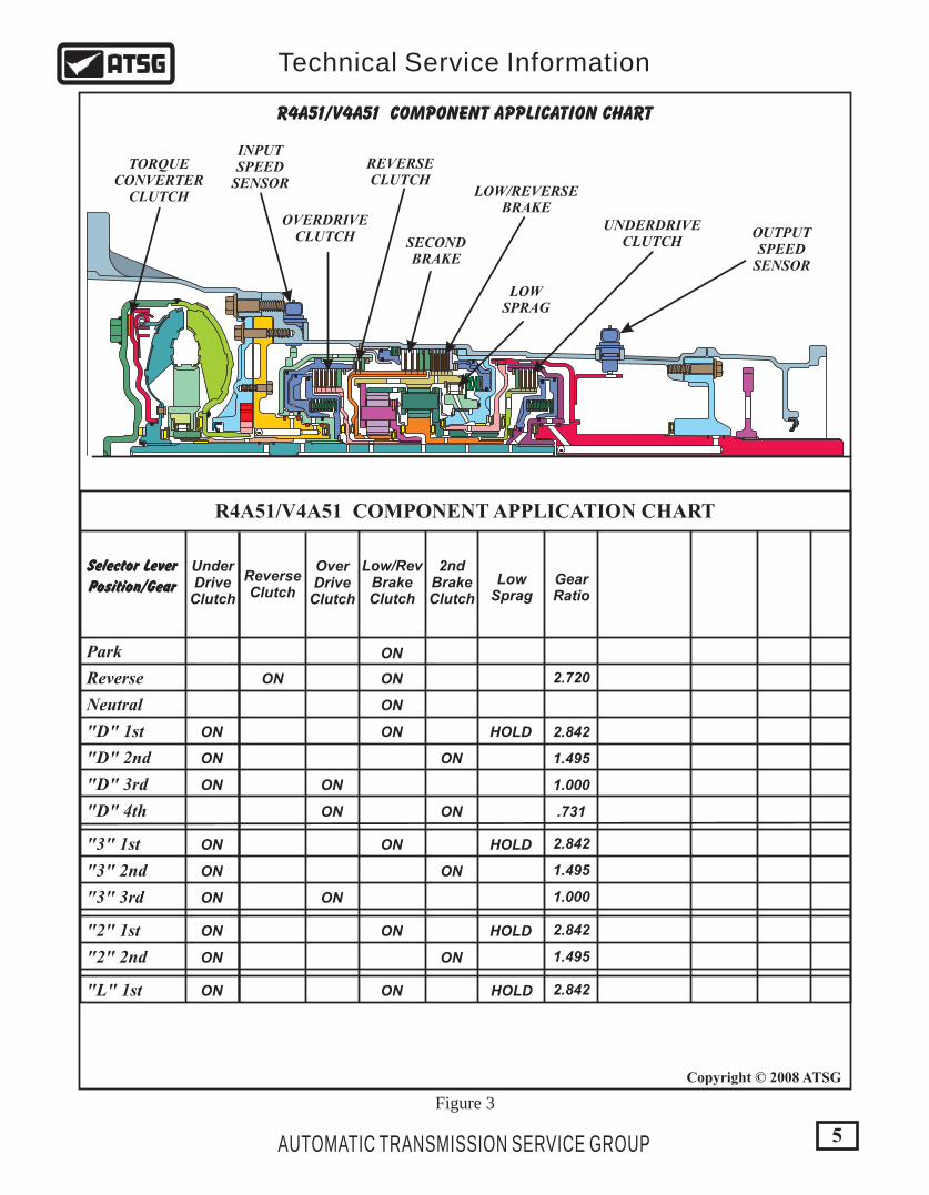
This is a four speed, Rear Wheel Drive transmission, with fully electronic controls for the upshifts and downshifts, with 4th gear being overdrive. The individual gear ratios are achieved through two planetary gear sets connected one behind the other. The components of the planetary gear sets are driven or held by means of five multiple plate clutch packs, and a low sprag. To minimize fuel consumption, the torque converter clutch is applied by the PCM, depending on throttle position and vehicle speed. These units are currently found in Mitsubishi Montero 1999-2002 models, equipped with 3.0L and 3.5L engines.
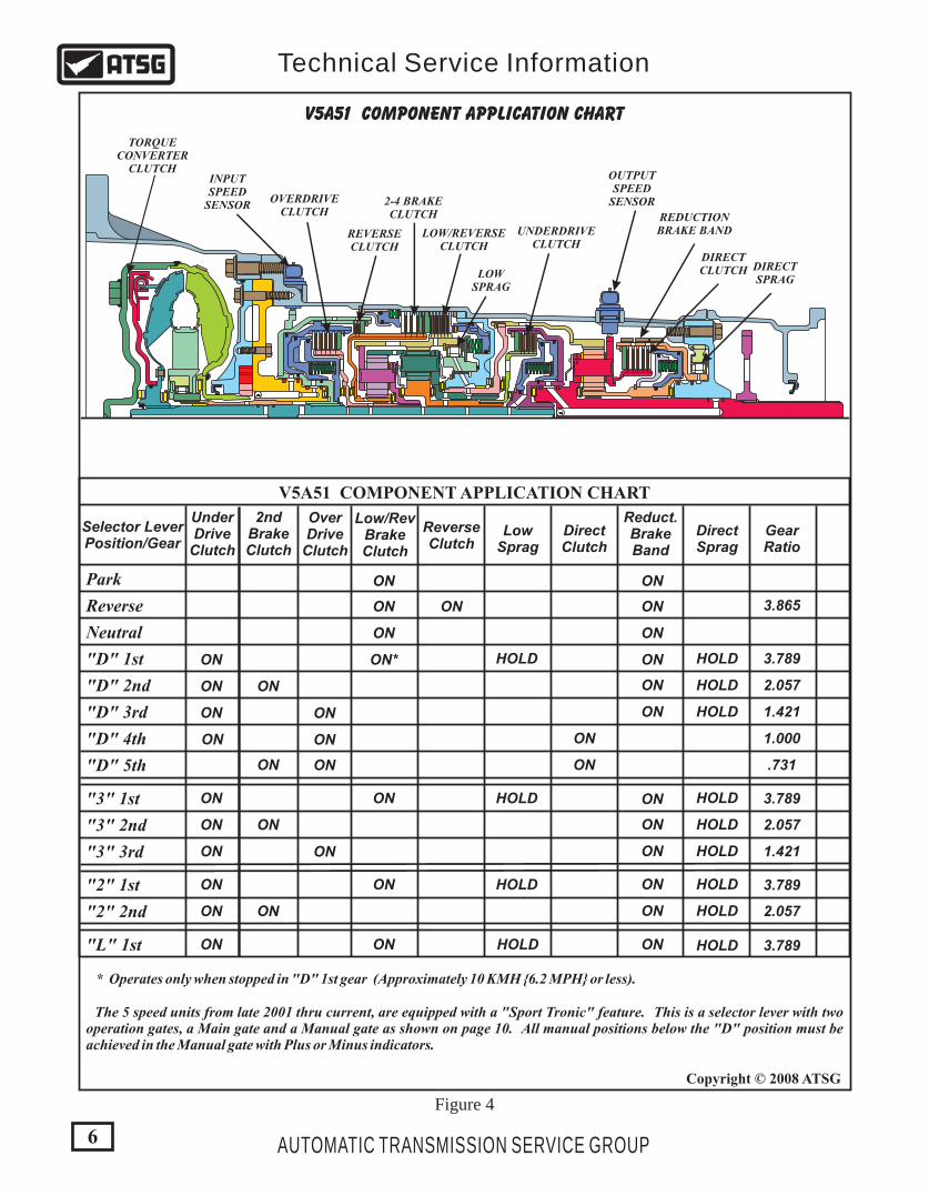
This is a five speed, Rear Wheel Drive transmission, with fully electronic controls for the upshifts and downshifts, with 5th gear being overdrive. The individual gear ratios are achieved through 3 planetary gear sets connected one behind the other. The components of the planetary gear sets are driven or held by means of six multiple plate clutch packs, 1 band, and two sprags. To minimize fuel consumption, the torque converter clutch is applied by the PCM, depending on throttle position and vehicle speed. These units are currently found in Mitsubishi Montero 2001-Up models, equipped with 3.5L and 3.8L engines.
We wish to thank Mitsubishi Motor Company for the information and illustrationsthat have made this booklet possible. A special thanks also to Bob Nuttall for
information and suggestions that has made this a very accurate booklet.
R/V4A51 R=2WD, V=4WD
V5A51 V=4WD
3
Copyright © 2008 ATSG
AUTOMATIC TRANSMISSION SERVICE GROUP
Technical Service Information
PREFACE The information contained within this manual is designed as both a teaching aid and self learning guide for automotive technicians, who aspire to broaden their working knowledge of automatic transmissions. A basic understanding of hydraulics and electronics is also a prerequisite to mastering this transmission. This manual will cover both the 4 speed unit (R/V4A51), and the 5 speed unit (V5A51), in both the "R" 2WD and "V" 4WD versions. Currently, there are no 2WD 5 speed units available, only the 4 speed.
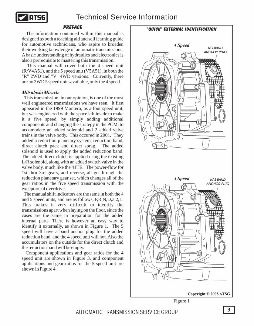
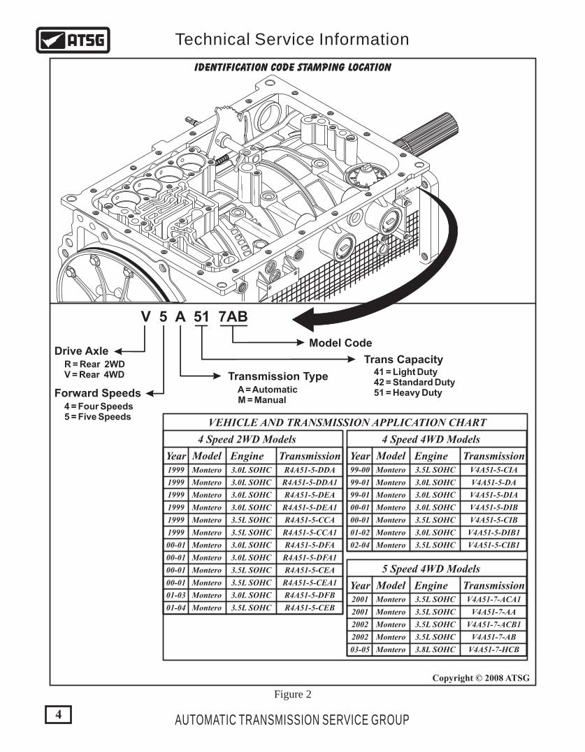
Mitsubishi Miracle This transmission, in our opinion, is one of the most well engineered transmissions we have seen. It first appeared in the 1999 Montero, as a four speed unit, but was engineered with the space left inside to make it a five speed, by simply adding additional components and changing the strategy in the PCM, to accomodate an added solenoid and 2 added valve trains in the valve body. This occured in 2001. They added a reduction planetary system, reduction band, direct clutch pack and direct sprag. The added solenoid is used to apply the added reduction band. The added direct clutch is applied using the existing L/R solenoid, along with an added switch valve in the valve body, much like the 41TE. The power-flow for 1st thru 3rd gears, and reverse, all go through the reduction planetary gear set, which changes all of the gear ratios in the five speed transmission with the exception of overdrive. The manual shift indicators are the same in both the 4 and 5 speed units, and are as follows, P,R,N,D,3,2,L. This makes it very difficult to identify the transmissions apart when laying on the floor, since the cases are the same in preparation for the added internal parts. There is however an easy way to identify it externally, as shown in Figure 1. The 5 speed will have a band anchor plug for the added reduction band, and the 4 speed unit will not. Also the accumulators on the outside for the direct clutch and the reduction band will be empty. Component applications and gear ratios for the 4 speed unit are shown in Figure 3, and component applications and gear ratios for the 5 speed unit are shown in Figure 4.
4 Speed
5 Speed HAS BANDANCHOR PLUG
NO BANDANCHOR PLUG
Figure 1
"QUICK" EXTERNAL IDENTIFICATION
4
Copyright © 2008 ATSG
AUTOMATIC TRANSMISSION SERVICE GROUP
Technical Service Information
6 00
6 00
1010
V5A51 7AB
BL7430
IDENTIFICATION CODE STAMPING LOCATION
V 5 A 51 7AB
Drive AxleModel Code
Forward Speeds
Transmission Type
Trans Capacity R = Rear 2WD V = Rear 4WD
4 = Four Speeds 5 = Five Speeds
A = Automatic M = Manual
41 = Light Duty 42 = Standard Duty 51 = Heavy Duty
VEHICLE AND TRANSMISSION APPLICATION CHART
Year1999
1999
1999
1999
1999
1999
00-01
00-01
00-01
00-01
01-03
01-04
ModelMontero
Montero
Montero
Montero
Montero
Montero
Montero
Montero
Montero
Montero
Montero
Montero
Engine
4 Speed 2WD Models
3.0L SOHC
3.0L SOHC
3.0L SOHC
3.0L SOHC
3.5L SOHC
3.5L SOHC
3.0L SOHC
3.0L SOHC
3.5L SOHC
3.5L SOHC
3.0L SOHC
3.5L SOHC
TransmissionR4A51-5-DDA
R4A51-5-DDA1
R4A51-5-DEA
R4A51-5-DEA1
R4A51-5-CCA
R4A51-5-CCA1
R4A51-5-DFA
R4A51-5-DFA1
R4A51-5-CEA
R4A51-5-CEA1
R4A51-5-DFB
R4A51-5-CEB
Year
99-01
99-00
99-01
00-01
00-01
01-02
02-04
Model
Montero
Montero
Montero
Montero
Montero
Montero
Montero
Engine
4 Speed 4WD Models
3.0L SOHC
3.5L SOHC
3.0L SOHC
3.0L SOHC
3.5L SOHC
3.0L SOHC
3.5L SOHC
Transmission
V4A51-5-DA
V4A51-5-CIA
V4A51-5-DIA
V4A51-5-DIB
V4A51-5-CIB
V4A51-5-DIB1
V4A51-5-CIB1
Year2001
2001
2002
2002
03-05
ModelMontero
Montero
Montero
Montero
Montero
Engine
5 Speed 4WD Models
3.5L SOHC
3.5L SOHC
3.5L SOHC
3.5L SOHC
3.8L SOHC
TransmissionV4A51-7-ACA1
V4A51-7-AA
V4A51-7-ACB1
V4A51-7-AB
V4A51-7-HCB
Figure 2
5
Copyright © 2008 ATSG
AUTOMATIC TRANSMISSION SERVICE GROUP
Technical Service Information
Selector LeverPosition/Gear
UnderDrive
Clutch
ReverseClutch
OverDrive
Clutch
Low/RevBrakeClutch
2ndBrakeClutch
LowSprag
GearRatio
Park
Reverse
Neutral
"D" 1st
"D" 2nd
"D" 3rd
"D" 4th
"3" 1st
"3" 2nd
"3" 3rd
"2" 1st
"2" 2nd
"L" 1st
ON
ON ON
ON
ON ON HOLD 2.842
2.720
2.842
2.842
2.842
1.495
1.495
1.495
1.000
1.000
.731
ON ON
ON ON
ON ON
ON ON HOLD
ON ON
ON ON
ON ON HOLD
ON ON
ON ON HOLD
R4A51/V4A51 COMPONENT APPLICATION CHART
Figure 3
OVERDRIVECLUTCH
REVERSECLUTCH
SECONDBRAKE
LOW/REVERSEBRAKE
UNDERDRIVECLUTCH
LOWSPRAG
TORQUECONVERTER
CLUTCH
INPUTSPEED
SENSOR
OUTPUTSPEED
SENSOR
R4A51/V4A51 COMPONENT APPLICATION CHART
Selector LeverPosition/Gear
UnderDrive
Clutch
OverDrive
Clutch
Low/RevBrakeClutch
2ndBrakeClutch
LowSprag
DirectSprag
Reduct.BrakeBand
DirectClutch
GearRatio
Park
Reverse
Neutral
"D" 1st
"D" 2nd
"D" 3rd
"D" 4th
"D" 5th
"3" 1st
"3" 2nd
"3" 3rd
"2" 1st
"2" 2nd
"L" 1st
ON ON
ReverseClutch
ONON ON
ON ON
ON ON* ON
ON
ON
ON
ON
ON
ON
ON
ON
ON
HOLD HOLD
HOLD
HOLD
HOLD
HOLD
HOLD
HOLD
HOLD
HOLD
3.865
3.789
3.789
3.789
3.789
2.057
2.057
2.057
1.000
1.421
1.421
.731
ON ON
ON ON
ON
ON
ON
ON ON
ON ON HOLD
ON ON
ON ON
ON ON HOLD
ON ON
ON ON HOLD
Figure 4
V5A51 COMPONENT APPLICATION CHART
OUTPUTSPEED
SENSOR
UNDERDRIVECLUTCH
LOWSPRAG
LOW/REVERSECLUTCH
REVERSECLUTCH
2-4 BRAKECLUTCH
OVERDRIVECLUTCH
DIRECTCLUTCH
REDUCTIONBRAKE BAND
INPUTSPEED
SENSOR
DIRECTSPRAG
* Operates only when stopped in "D" 1st gear (Approximately 10 KMH {6.2 MPH} or less).
The 5 speed units from late 2001 thru current, are equipped with a "Sport Tronic" feature. This is a selector lever with two operation gates, a Main gate and a Manual gate as shown on page 10. All manual positions below the "D" position must be achieved in the Manual gate with Plus or Minus indicators.
6
Copyright © 2008 ATSG
AUTOMATIC TRANSMISSION SERVICE GROUP
Technical Service Information
V5A51 COMPONENT APPLICATION CHART
TORQUECONVERTER
CLUTCH
7
Copyright © 2008 ATSG
AUTOMATIC TRANSMISSION SERVICE GROUP
Technical Service Information
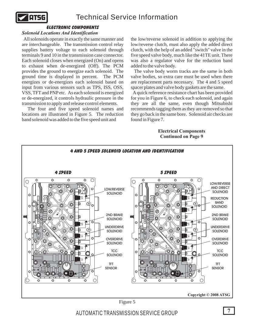
ELECTRONIC COMPONENTSSolenoid Locations And Identification
All solenoids operate in exactly the same manner and are interchangeable. The transmission control relay supplies battery voltage to each solenoid through terminals 9 and 10 in the transmission case connector. Each solenoid closes when energized (On) and opens to exhaust when de-energized (Off). The PCM provides the ground to energize each solenoid. The ground time is displayed in percent. The PCM energizes or de-energizes each solenoid based on input from various sensors such as TPS, ISS, OSS, VSS, TFT and PNP etc. As each solenoid is energized or de-energized, it controls hydraulic pressure in the transmission to apply and release control elements. The four and five speed solenoid names and locations are illustrated in Figure 5. The reduction band solenoid was added to the five speed unit and
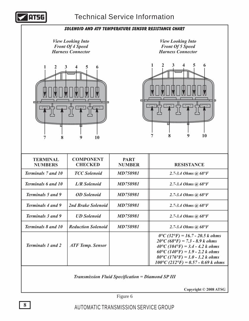
the low/reverse solenoid in addition to applying the low/reverse clutch, must also apply the added direct clutch, with the help of an added "switch" valve in the five speed valve body, much like the 41TE unit. There was also a regulator valve for the reduction band added to the valve body. The valve body worm tracks are the same in both valve bodies, so extra care must be used when there are replacement parts necessary. The 4 and 5 speed spacer plates and valve body gaskets are the same. A quick reference resistance chart has been provided for you in Figure 6, to check each solenoid, and again they are all the same, even though Mitsubishi recommends tagging them as they are removed so that they go back in the same bore. Solenoid air checks are found in Figure 7.
006
0X18
- 2
- 2
777
006
0X18
- 2
- 2
777
4 AND 5 SPEED SOLENOID LOCATION AND IDENTIFICATION
4 SPEED 5 SPEED
Figure 5
LOW/REVERSESOLENOID
LOW/REVERSEAND DIRECTSOLENOID
REDUCTIONBAND
SOLENOID
2ND BRAKESOLENOID
2ND BRAKESOLENOID
UNDERDRIVESOLENOID
UNDERDRIVESOLENOID
OVERDRIVESOLENOID
OVERDRIVESOLENOID
TCCSOLENOID
TCCSOLENOID
TFTSENSOR
TFTSENSOR
Electrical ComponentsContinued on Page 9
8
Copyright © 2008 ATSG
AUTOMATIC TRANSMISSION SERVICE GROUP
Technical Service Information
SOLENOID AND ATF TEMPERATURE SENSOR RESISTANCE CHART
TERMINALNUMBERS
Terminals 7 and 10
Terminals 6 and 10
Terminals 5 and 9
Terminals 4 and 9
Terminals 3 and 9
Terminals 8 and 10
Terminals 1 and 2
TCC Solenoid MD758981
MD758981
MD758981
MD758981
MD758981
MD758981
L/R Solenoid
OD Solenoid
2nd Brake Solenoid
UD Solenoid
Reduction Solenoid
ATF Temp. Sensor
0°C (32°F) = 16.7 - 20.5 k ohms20°C (68°F) = 7.3 - 8.9 k ohms40°C (104°F) = 3.4 - 4.2 k ohms60°C (140°F) = 1.9 - 2.2 k ohms80°C (176°F) = 1.0 - 1.2 k ohms
100°C (212°F) = 0.57 - 0.69 k ohms
2.7-3.4 Ohms @ 68°F
2.7-3.4 Ohms @ 68°F
2.7-3.4 Ohms @ 68°F
2.7-3.4 Ohms @ 68°F
2.7-3.4 Ohms @ 68°F
2.7-3.4 Ohms @ 68°F
COMPONENTCHECKED RESISTANCE
PARTNUMBER
Figure 6
1 12 23 34 45 56 6
7 78 89 910 10
View Looking IntoFront Of 4 Speed
Harness Connector
View Looking IntoFront Of 5 Speed
Harness Connector
Transmission Fluid Specification = Diamond SP III
MADE IN U.S.A
AIR OUT
NO AIR
9
Copyright © 2008 ATSG
Copyright © 2008 ATSG
AUTOMATIC TRANSMISSION SERVICE GROUP
Technical Service Information
LinePressure
Feed
PressureOut To
ComponentControledExhaust
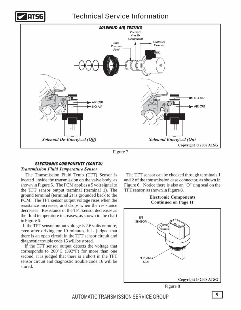
Solenoid De-Energized (Off) Solenoid Energized (On)
TFTSENSOR
"O" RINGSEAL
MADE IN U.S.A
AIR OUT
NO AIR
SOLENOID AIR TESTING
Figure 7
ELECTRONIC COMPONENTS (CONT'D)Transmission Fluid Temperature Sensor
The Transmission Fluid Temp (TFT) Sensor is located inside the transmission on the valve body, as shown in Figure 5. The PCM applies a 5 volt signal to the TFT sensor output terminal (terminal 1). The ground terminal (terminal 2) is grounded back to the PCM. The TFT sensor output voltage rises when the resistance increases, and drops when the resistance decreases. Resistance of the TFT sensor decreases as the fluid temperature increases, as shown in the chart in Figure 6. If the TFT sensor output voltage is 2.6 volts or more, even after driving for 10 minutes, it is judged that there is an open circuit in the TFT sensor circuit and diagnostic trouble code 15 will be stored. If the TFT sensor output detects the voltage that corresponds to 200°C (392°F) for more than one second, it is judged that there is a short in the TFT sensor circuit and diagnostic trouble code 16 will be stored.
The TFT sensor can be checked through terminals 1 and 2 of the transmission case connector, as shown in Figure 6. Notice there is also an "O" ring seal on the TFT sensor, as shown in Figure 8.
Electronic ComponentsContinued on Page 11
Figure 8
X1000 r/min
876
54
3
2
1
0
ND
54321
RP
X1000 r/min
876
54
3
2
1
0
ND
3
2
L
RP
H
C
X1000 r/min0
1
23 4 5
6
7
8L
2
3
D
N
R
P
P
R +
N
D
P
R
N
D
3
2
L
P
R
N
D
3
2
L
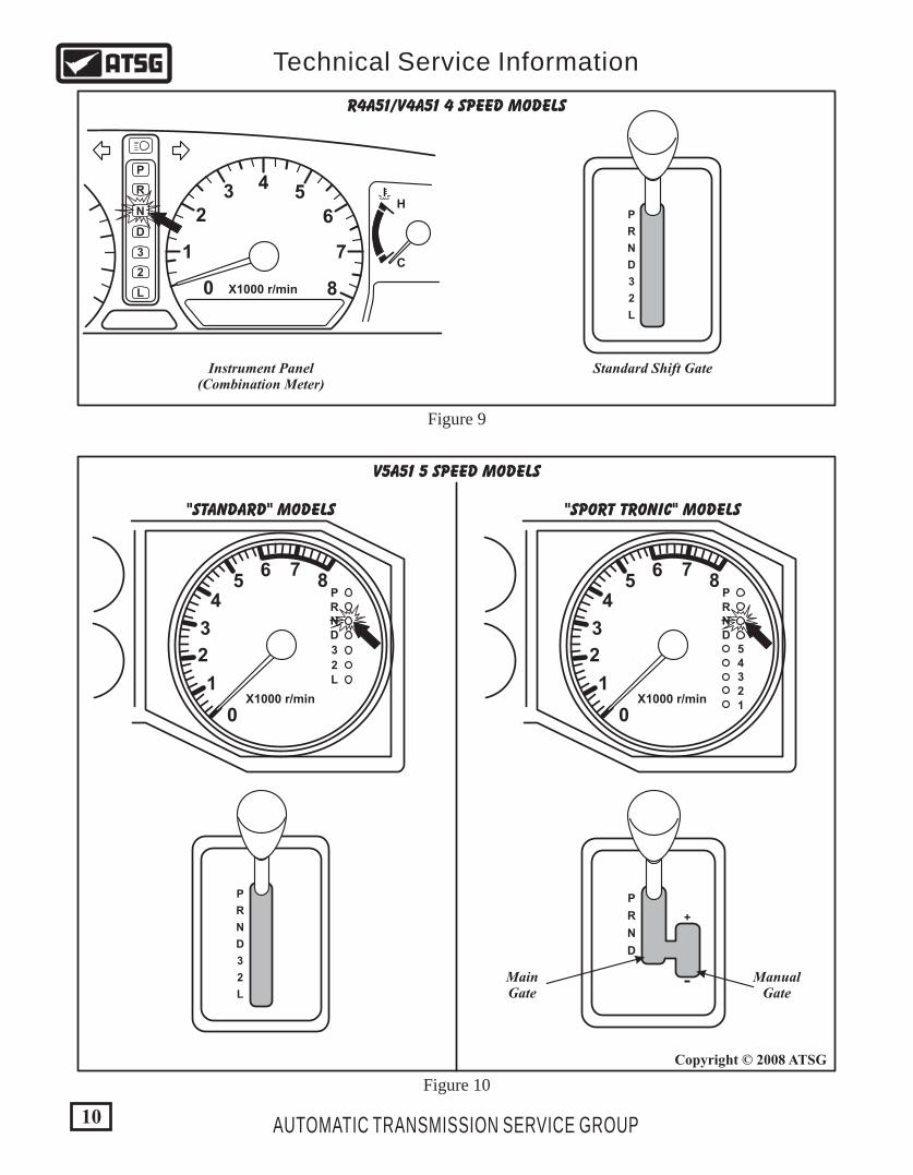
R4A51/V4A51 4 SPEED MODELS
V5A51 5 SPEED MODELS
"STANDARD" MODELS "SPORT TRONIC" MODELS
Instrument Panel(Combination Meter)
Standard Shift Gate
ManualGate
MainGate
Figure 9
Figure 10
10
Copyright © 2008 ATSG
AUTOMATIC TRANSMISSION SERVICE GROUP
Technical Service Information
11
Copyright © 2008 ATSG
AUTOMATIC TRANSMISSION SERVICE GROUP
Technical Service Information
ELECTRONIC COMPONENTS (CONT'D)Manual Shift Gate (4 Speed Models) Trouble Code Diagnosis
Check "N" Range Light
"Standard" Shift Gate (5 Speed Models)
"Sport Tronic" Shift Gate (5 Speed Models)
A 7 position (P, R, N, D, 3, 2, L) manual selector lever is used in all vehicles with the 4 speed transmission. The Manual Selector Lever assembly and indicators in the instrument panel are illustrated in Figure 9. Each indicator represents the gear that is selected with the manual selector lever. Mitsubishi refers to the instrument panel as a "Combination Meter" in their wire schematics and text.
A 7 position (P, R, N, D, 3, 2, L) manual selector lever is used in some 2001 vehicles equipped with the 5 speed transmission. The Manual Selector Lever assembly and indicators in the instrument panel are illustrated in Figure 10. Each indicator represents the gear that is selected with the manual selector lever. Mitsubishi refers to the instrument panel as a "Combination Meter" in their wire schematics and text.
A 4 position (P, R, N, D) Sport Tronic selector lever is used in some 2001 vehicles equipped with the 5 speed transmission. The Manual Selector Lever assembly and indicators in the instrument panel are illustrated in Figure 10. Each indicator represents the gear that is selected with the manual selector lever. The 5 speed units from late 2001 thru current, are equipped with a "Sport Tronic" feature. This is a selector lever with two operation gates, a Main gate and a Manual gate, and is shown in Figure 10. All manual positions below the "D" position must be selected using the Manual gate with the Plus or Minus indicators. Please refer to Figure 10. Mitsubishi refers to the instrument panel as a "Combination Meter" in their wire schematics and text.
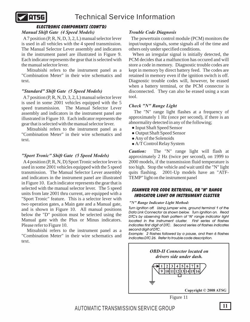
SCANNER FOR CODE RETRIEVAL, OR "N" RANGEINDICATOR LIGHT ON INSTRUMENT CLUSTER
OBD-II Connector located ondrivers side under dash.
"N" Range Indicator Light Method:
1
9
2
10
3
11
4
12
5
13
6
14
7
15
8
16
Turn ignition off. Using jumper wire, ground terminal 1 of the Data Link Connector as shown below. Turn ignition on. Read DTC's by observing flash pattern of "N" range indicator light located in the instrument cluster. First series of flashes indicates first digit of DTC. Second series of flashes indicates second digit of DTC.Example: 2 flashes followed by a pause, and then 6 flashes indicates DTC 26. Refer to trouble code description.
The powertrain control module (PCM) monitors the input/output signals, some signals all of the time and others only under specified conditions. When an irregular signal is initially detected, the PCM decides that a malfunction has occured and will store a code in memory. Diagnostic trouble codes are kept in memory by direct battery feed. The codes are retained in memory even if the ignition switch is off. Diagnostic trouble codes will, however, be erased when a battery terminal, or the PCM connector is disconnected. They can also be erased using a scan tool.
The "N" range light flashes at a frequency of approximately 1 Hz (once per second), if there is an abnormality detected in any of the following; Input Shaft Speed Sensor Output Shaft Speed Sensor Any of the Solenoids A/T Control Relay System
Caution: The "N" range light will flash at approximately 2 Hz (twice per second), on 1999 to 2000 models, if the transmission fluid temperature is too high. Stop the vehicle and wait until the "N" light quits flashing. 2001-Up models have an "ATF-TEMP" light on the instrument panel
Figure 11
12
Copyright © 2008 ATSG
Copyright © 2008 ATSG
AUTOMATIC TRANSMISSION SERVICE GROUP
Technical Service Information
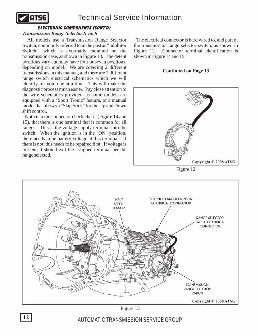
All models use a Transmission Range Selector Switch, commonly referred to in the past as "Inhibitor Switch", which is externally mounted on the transmission case, as shown in Figure 13. The detent positions vary and may have four or seven positions, depending on model. We are covering 2 different transmissions in this manual, and there are 2 different range switch electrical schematics which we will identify for you, one at a time. This will make the diagnostic process much easier. Pay close attention to the wire schematics provided, as some models are equipped with a "Sport Tronic" feature, or a manual mode, that allows a "Slap Stick" for the Up and Down shift control. Notice in the connector check charts (Figure 14 and 15), that there is one terminal that is common for all ranges. This is the voltage supply terminal into the switch. When the ignition is in the "ON" position, there needs to be battery voltage at this terminal. If there is not, this needs to be repaired first. If voltage is present, it should exit the assigned terminal per the range selected.
B 2
TRANSMISSIONRANGE SELECTOR
SWITCH
RANGE SELECTORSWITCH ELECTRICAL
CONNECTOR
SOLENOID AND TFT SENSORELECTRICAL CONNECTOR
INPUTSPEED
SENSOR
Figure 13
ELECTRONIC COMPONENTS (CONT'D)Transmission Range Selector Switch
B 2
The electrical connector is hard wired to, and part of the transmission range selector switch, as shown in Figure 12. Connector terminal identification is shown in Figure 14 and 15.
Figure 12
Continued on Page 13
13
Copyright © 2008 ATSGCopyright © 2008 ATSG
AUTOMATIC TRANSMISSION SERVICE GROUP
Technical Service Information
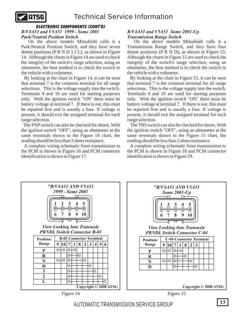
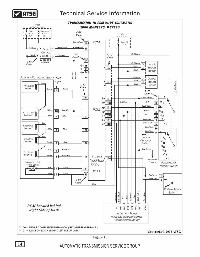
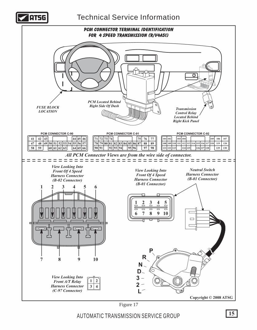
On the above models Mitsubishi calls it a Park/Neutral Position Switch, and they have seven detent positions (P R N D 3 2 L), as shown in Figure 14. Although the charts in Figure 14 are used to check the integrity of the switch's range selection, using an ohmmeter, the best method is to check the switch in the vehicle with a voltmeter. By looking at the chart in Figure 14, it can be seen that terminal 7 is the common terminal for all range selections. This is the voltage supply into the switch. Terminals 9 and 10 are used for starting purposes only. With the ignition switch "ON" there must be battery voltage at terminal 7. If there is not, this must be repaired first and is usually a fuse. If voltage is present, it should exit the assigned terminal for each range selection. The PNP switch can also be checked for shorts. With the ignition switch "OFF", using an ohmmeter at the same terminals shown in the Figure 14 chart, the reading should be less than 2 ohms resistance. A complete wiring schematic from transmission to the PCM is shown in Figure 16 and PCM connector identification is shown in Figure 17.
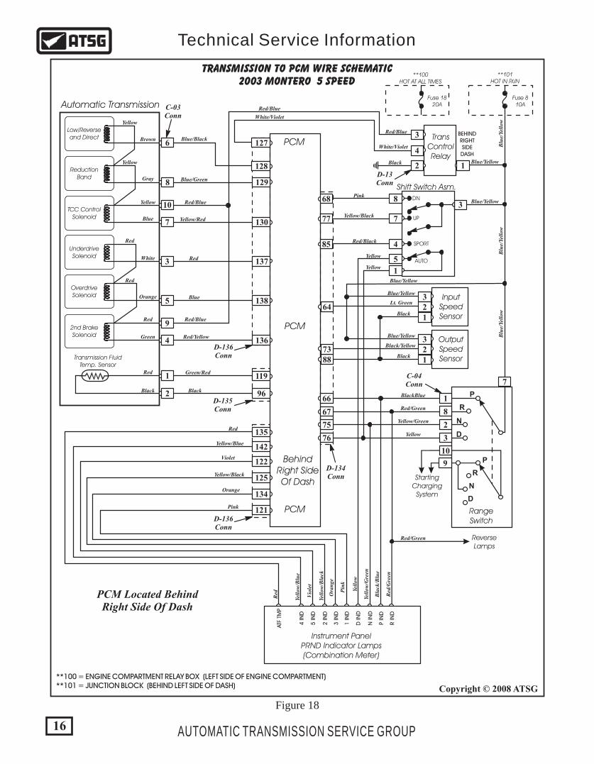
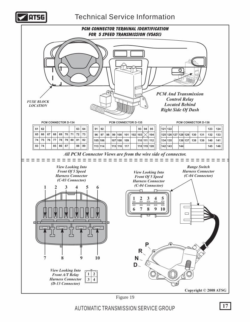
On the above models Mitsubishi calls it a Transmission Range Switch, and they have four detent positions (P R N D), as shown in Figure 15. Although the charts in Figure 15 are used to check the integrity of the switch's range selection, using an ohmmeter, the best method is to check the switch in the vehicle with a voltmeter. By looking at the chart in Figure 15, it can be seen that terminal 7 is the common terminal for all range selections. This is the voltage supply into the switch. Terminals 9 and 10 are used for starting purposes only. With the ignition switch "ON" there must be battery voltage at terminal 7. If there is not, this must be repaired first and is usually a fuse. If voltage is present, it should exit the assigned terminal for each range selection. The TRS switch can also be checked for shorts. With the ignition switch "OFF", using an ohmmeter at the same terminals shown in the Figure 15 chart, the reading should be less than 2 ohms resistance. A complete wiring schematic from transmission to the PCM is shown in Figure 18 and PCM connector identification is shown in Figure 19.
R/V4A51 and V5A51 1999 - Some 2001Park/Neutral Position Switch
R/V4A51 and V5A51 Some 2001-UpTransmission Range Switch
ELECTRONIC COMPONENTS (CONT'D)
View Looking Into TransaxlePRNDL Switch Connector B-01
"R/V4A51 AND V5A511999 - Some 2001
1
6
2
7
3
8
4
9
5
10
Position/Range
B-02 Connector Terminal
9 10 7 1 8 2 3 4 5 6
PRND32L
View Looking Into TransaxlePRNDL Switch Connector C-04
"R/V4A51 AND V5A51Some 2001-Up
1
6
2
7
3
8
4
9
5
10
Position/Range
C-04 Connector Terminal
9 10 7 1 8 2 3
PRND
Figure 14 Figure 15
Low/ReverseSolenoid
TCC ControlSolenoid
UnderdriveSolenoid
OverdriveSolenoid
2nd BrakeSolenoid
TRANSMISSION TO PCM WIRE SCHEMATIC2000 MONTERO 4 SPEED
PCM
PCM
BehindRight SideOf Dash
PCM
PCM Located behindRight Side of Dash
Transmission FluidTemp. Sensor
Automatic Transmission B-02Conn
C-90Conn
C-90Conn
C-97Conn
C-91Conn
C-92Conn
C-92Conn
129
6
10
7 107
3 120
5
4
9
130
106
50
66
89
889776
1
2
4
32
1
124
TransControlRelay
FuseLink 640A
DedicatedFuse 510A
Fuse 1010A
**101HOT IN RUN
**100HOT AT ALL TIMES
Red Red/Blue
Red/Blue
Red/Blue
Red
/Blu
e
Red
/Blu
e
White
Red
Black Black
Black
Black
Yellow
White/Green White/Green
Black/Green
Red/Green
Red/Green
Red/Green
Black/Yellow
Black/White
Bla
ck/W
hit
e
Bla
ck/Y
ello
w
RedRed/Blue
Yellow/Black
Yellow/Red
Yellow
Blue
Blue/Black
Blue/Black
Red
/Gre
en
Black
Yellow
Yellow
Red
Red
Black
Green BlackRed
Orange Blue
Green
White
Blue
Brown
Pattern SelectSwitch
1
2Green/Blue
Gre
en/B
lue
Red/Green
ReverseLamps
Red/Green
Red
Yell
ow
Blu
e
Yell
ow/B
lack
Yell
ow/R
ed
P IN
D
L IN
D
R IN
D
3 IN
D
N IN
D
2 IN
D
D IN
D
HO
LD
Instrument PanelPRND32L Indicator Lamps
(Combination Meter)
**100 = ENGINE COMPARTMENT RELAY BOX (LEFT INNER FENDER PANEL) **101 = JUNCTION BLOCK (BEHIND LEFT SIDE OF DASH)
D
N
R
P
3
2
L
Park/NeutralPosition Switch
StartingCharging
System
1
8
2
3
4
5
6
10
9
7
D
N
R
P
3
2
L
D
N
R
P
3
2
1
InputSpeedSensor
OutputSpeedSensor
3
3
2
2
1
1
White
Black
Black
Black
103
104
101
108
121
102
109
122
110
126
BEHIND RIGHTKICK PANEL
B-01Conn
50
14
Copyright © 2008 ATSG
AUTOMATIC TRANSMISSION SERVICE GROUP
Technical Service Information
Figure 16
15
Copyright © 2008 ATSG
AUTOMATIC TRANSMISSION SERVICE GROUP
Technical Service Information
FUSE BLOCKLOCATION
PCM CONNECTOR TERMINAL IDENTIFICATIONFOR 4 SPEED TRANSMISSION (R/V4A51)
654321
7 8 9 10
View Looking IntoFront Of 4 Speed
Harness Connector(B-02 Connector)
View Looking IntoFront A/T Relay
Harness Connector(C-97 Connector)
View Looking IntoFront Of 4 Speed
Harness Connector(B-01 Connector)
Neutral SwitchHarness Connector(B-01 Connector)
PCM Located BehindRight Side Of Dash
TransmissionControl Relay
Located BehindRight Kick Panel
All PCM Connector Views are from the wire side of connector.
PCM CONNECTOR C-90 PCM CONNECTOR C-91 PCM CONNECTOR C-92
41
47 48 49 50 51 52 53 54 55 56 57
58 59 60 61 62 63 64 65 66
42 43 44 45 46
125 126 127 128 129 130124123122121
113 114 115 116 117 118 119 120112111110109108
104 105 106 10710310210171 72 73 74 75 76 77
78 79 80 81 82 83 84 85 86 87 88 89
90 91 92 93 94 95 96 97 98
1
6
2
7
3
8
4
9
5
10
Figure 17
32L
PR
ND
B 223
1
3
2
4
16
Copyright © 2008 ATSG
AUTOMATIC TRANSMISSION SERVICE GROUP
Technical Service Information
Low/Reverseand Direct
ReductionBand
TCC ControlSolenoid
UnderdriveSolenoid
OverdriveSolenoid
2nd BrakeSolenoid
TRANSMISSION TO PCM WIRE SCHEMATIC2003 MONTERO 5 SPEED
PCM
PCM
BehindRight SideOf Dash
PCM
PCM Located BehindRight Side Of Dash
Transmission FluidTemp. Sensor
Automatic Transmission C-03Conn
D-13Conn
D-136Conn
D-136Conn
D-135Conn
C-04Conn
127
128
6
10
7 130
3 137
5
4
9
138
136
InputSpeedSensor
OutputSpeedSensor
3
3
2
2
1
188
64
73
1
2
3
4
2 1
3
135
119
142
122
125
134
121
96
8 129Shift Switch Asm.
UP
SPORT
AUTO
DN68 8
77 7
85
5
4
1
D-134Conn
D
D
N
N
R
R
P
P
RangeSwitch
StartingCharging
System
ReverseLamps
66
67
1
8
75 2
76 3
10
9
7
TransControlRelay
Fuse 1820A
Fuse 810A
**101HOT IN RUN
**100HOT AT ALL TIMES
Red Red/Blue
Red/Blue
Red/Blue
White/Violet
White/Violet
Red/Blue
Red
Black Black
Green/Red
Yellow
Yellow
Yellow
Yellow/Black
Blue/Yellow
Blue/Yellow
Blue/Yellow
Blue/Yellow
Blue/Yellow
BlackBlue
Red/Green
Red/Green
Red
/Gre
en
Bla
ck/B
lue
Yell
ow/G
reen
Yell
ow
Pin
k
Pink
Vio
let
Violet
Red
Red
Yell
ow/B
lack
Yellow/Black
Yell
ow/B
lue
Yellow/Blue
Ora
nge
Orange
Yellow/Green
Yellow
Black/Yellow
Lt. Green
Black
Black
Blu
e/Ye
llow
Blu
e/Ye
llow
Blu
e/Ye
llow
Pink
Red/Black
Black
Yellow/Red
Yellow
Yellow
Red
Red
Red
Green Red/Yellow
Orange Blue
Blue/Green
Blue/Black
White
Blue
Gray
Brown
R IN
D
1 IN
D
P IN
D
3 IN
D
N IN
D
2 IN
D
D IN
D
5 IN
D
4 IN
D
ATF
TM
P
Instrument PanelPRND Indicator Lamps(Combination Meter)
**100 = ENGINE COMPARTMENT RELAY BOX (LEFT SIDE OF ENGINE COMPARTMENT) **101 = JUNCTION BLOCK (BEHIND LEFT SIDE OF DASH)
BEHINDRIGHTSIDEDASH
Figure 18
17
Copyright © 2008 ATSG
AUTOMATIC TRANSMISSION SERVICE GROUP
Technical Service Information
121
125
134
142
122
126
135
143
127 128
136
144
129
137
130
138
131
139
123
PCM CONNECTOR D-136
132
140
145
124
133
141
146
91
96
105
113
92
97
106
114
98 99
107
115 116 117
100
108
101
109
102
9493
PCM CONNECTOR D-135
103
111110
119118
95
104
112
120
61
65
74
83
62
66
75
74
67
76
68
77
85
69
78
86
70
79
87
63
72
81
88
71
80
PCM CONNECTOR D-134
64
73
82
89
PCM CONNECTOR TERMINAL IDENTIFICATIONFOR 5 SPEED TRANSMISSION (V5A51)
1 2 3 4 5 6
7 8 9 10
View Looking IntoFront Of 5 Speed
Harness Connector(C-03 Connector)
View Looking IntoFront Of 5 Speed
Harness Connector(C-04 Connector)
PCM And TransmissionControl Relay
Located BehindRight Side Of Dash
Range SwitchHarness Connector(C-04 Connector)
All PCM Connector Views are from the wire side of connector.
1
6
2
7
3
8
4
9
5
10
Figure 19
PR
ND
B 223
FUSE BLOCKLOCATION
View Looking IntoFront A/T Relay
Harness Connector(D-13 Connector)
1
3
2
4

INPUT SPEED SENSOR INPUT SPEED SENSOR CIRCUIT OPERATION
CONDITIONS TO SET DTC
OUTPUT SPEED SENSOR CIRCUIT OPERATION
OUTPUT SPEED SENSOR
3
1
2
2
1
3
Bla
ck/O
ran
ge
Wh
ite
Bla
ckG
rou
ndPCM Terminal Numbers Vary
Between 4 and 5 Speed Units.(Refer to Wire Schematics Figure 16 and 18)
PCM Terminal Numbers VaryBetween 4 and 5 Speed Units.
(Refer to Wire Schematics Figure 16 and 18)
Sig
nal
Pow
er
3
1
2
2
1
3Black/Orange
Green/Yellow
BlackGround
Signal
Power
Figure 20
Figure 21
CONDITIONS TO SET DTC
When the key is turned on, you should see battery voltage at input speed sensor terminal 3. A coil built into the input shaft speed sensor generates a 0 - 5 volt pulse signal at both ends of this coil when the input shaft rotates. The pulse signal frequency increases with a rise in input shaft speed. Both ends of the coil are connected to the PCM, via the input shaft speed sensor connector (terminals 1 and 2), as shown in Figure 20. The PCM detects the input shaft speed by the signal input from terminal 2. The input shaft speed sensor generates the pulse signal as the teeth on the reverse clutch housing pass the magnetic tip of the sensor.
When the key is turned on, you should see battery voltage at output speed sensor terminal 3. A coil built into the output shaft speed sensor generates a 0-5 volt pulse signal at both ends of this coil when the output shaft rotates. The pulse signal frequency increases with a rise in output shaft speed. Both ends of the coil are connected to the PCM, via the output shaft speed sensor connector (terminals 1 and 2), as shown in Figure 21. The PCM detects the output shaft speed by the signal input from terminal 2. The output shaft speed sensor generates the pulse signal as the teeth on the output shaft pass the magnetic tip of the sensor.
If no output pulse is detected from the input shaft speed sensor for one second or more, while driving in 3rd or 4th gear at a speed of 30 km/h (19 mph) or more, there is an open or short in the input shaft speed sensor circuit, and a DTC is set. When a DTC is output four times, transmission is locked into 3rd or 2nd gear as a failsafe measure, and the "N" range light flashes once per second.
If the output from the output speed sensor is continuously 50% lower than vehicle speed for one second or more, while driving in 3rd or 4th gear at a speed of 30 km/h (19 mph) or more, there is an open or short in the output speed sensor circuit, and a DTC is set. When a DTC is output four times, the transmission is locked into 3rd or 2nd gear as a failsafe measure, and the "N" range light flashes once per second.
18
Copyright © 2008 ATSG
Copyright © 2008 ATSG
AUTOMATIC TRANSMISSION SERVICE GROUP
Technical Service Information
DIAGNOSTIC TROUBLE CODES
CODE OBD II COMPONENT DESCRIPTION11
12
14
15
16
21
22
23
26
27
28
29
31
32
33
34
*35
36
52
53
54
56
41
42
43
44
*45
46
P0705
----
P0500
P0753
P0758
P0763
P0768
P0773
P0743
P0741
P0742
P1751
----
P0731
P0732
P0733
P0734
P0735
P0736
P0715
P0720
P0713
P0712
Short Circuit
Open Circuit
Out Of Adjustment
Open Circuit
Short Circuit
Open Circuit
Open/Short Circuit
Open/Short Circuit
Short Circuit
Open Circuit
Short Circuit
Open/Short Circuit
Open/Short Circuit
Open/Short Circuit
Open/Short Circuit
Open/Short Circuit
Open/Short Circuit
Open/Short Circuit
Defective System
Clutch Stuck On
Open/Short Circuit
Open Circuit
Mechanical Solenoid FailureLow Line PressureLow Fluid LevelSealing Ring FailurePiston Seal FailureValve Body Malfunction
Throttle Position Sensor
Throttle Position Sensor
Throttle Position Sensor
Transmission Fluid Temperature System
Transmission Fluid Temperature System
Crankshaft Position Sensor System
Input Shaft Speed Sensor System
Output Shaft Speed Sensor System
Stoplight Switch System
Transmission Range Switch System
Transmission Range Switch System
Vehicle Speed Sensor System
Low/Reverse-Direct Solenoid System
Underdrive Solenoid System
2nd Brake Solenoid System
Overdrive Solenoid System
Reduction Band Solenoid System
Torque Converter Clutch Solenoid System
Torque Converter Clutch Solenoid System, Performance
Torque Converter Clutch Solenoid System
Transmission Control Relay System
"N" Range Light System
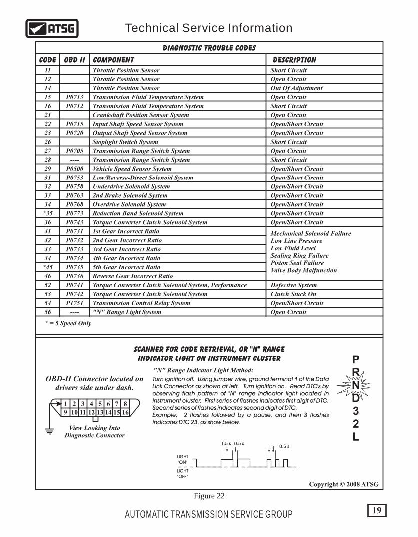
* = 5 Speed Only
1st Gear Incorrect Ratio
2nd Gear Incorrect Ratio
3rd Gear Incorrect Ratio
4th Gear Incorrect Ratio
5th Gear Incorrect Ratio
Reverse Gear Incorrect Ratio
SCANNER FOR CODE RETRIEVAL, OR "N" RANGEINDICATOR LIGHT ON INSTRUMENT CLUSTER
OBD-II Connector located ondrivers side under dash.
View Looking IntoDiagnostic Connector
"N" Range Indicator Light Method:
1
9
2
10
3
11
4
12
5
13
6
14
7
15
8
16
Turn ignition off. Using jumper wire, ground terminal 1 of the Data Link Connector as shown at left. Turn ignition on. Read DTC's by observing flash pattern of "N" range indicator light located in instrument cluster. First series of flashes indicates first digit of DTC. Second series of flashes indicates second digit of DTC.Example: 2 flashes followed by a pause, and then 3 flashes indicates DTC 23, as show below.
PRND32L
1.5 s 0.5 s
LIGHT"ON"
LIGHT"OFF"
0.5 s
19
Copyright © 2008 ATSG
AUTOMATIC TRANSMISSION SERVICE GROUP
Technical Service Information
Figure 22
ELECTRONIC CONTROLS (CONT'D)Innovative Electronic Control System
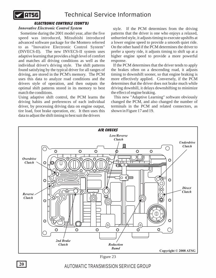
Sometime during the 2001 model year, after the five speed was introduced, Mitsubishi introduced advanced software package for the Montero referred to as "Inovative Electronic Control System" (INVECS-II). The new INVECS-II system uses adaptive learning that provides a high level of comfort and matches all driving conditions as well as the individual driver's driving style. The shift patterns found satisfying by the typical driver for all ranges of driving, are stored in the PCM's memory. The PCM uses this data to analyze road conditions and the drivers style of operation, and then outputs the optimal shift patterns stored in its memory to best match the conditions.Using adaptive shift control, the PCM learns the driving habits and preferences of each individual driver, by processing driving data on engine output, tire load, foot brake operation, etc. It then uses this data to adjust the shift timing to best suit the drivers
style. If the PCM determines from the driving patterns that the driver is one who enjoys a relaxed, unhurried style, it adjusts timing to execute upshifts at a lower engine speed to provide a smooth quiet ride. On the other hand if the PCM determines the driver to prefer a sporty ride, it adjusts timing to shift up at a higher engine speed to provide a more powerful response. If the PCM determines that the driver tends to apply the brakes often on a descending road, it adjusts timing to downshift sooner, so that engine braking is more effectively applied. Conversely, if the PCM determines that the driver does not brake much while driving downhill, it delays downshifting to minimize the effect of engine braking. This new "Adaptive Learning" software obviously changed the PCM, and also changed the number of terminals in the PCM and related connectors, as shown in Figure 17 and 19.
OverdriveClutch
UnderdriveClutch
DirectClutch
ReductionBamd
ReverseClutch
2nd BrakeClutch
Low/ReverseClutch
AIR CHECKS
20
Copyright © 2008 ATSG
AUTOMATIC TRANSMISSION SERVICE GROUP
Technical Service Information
Figure 23
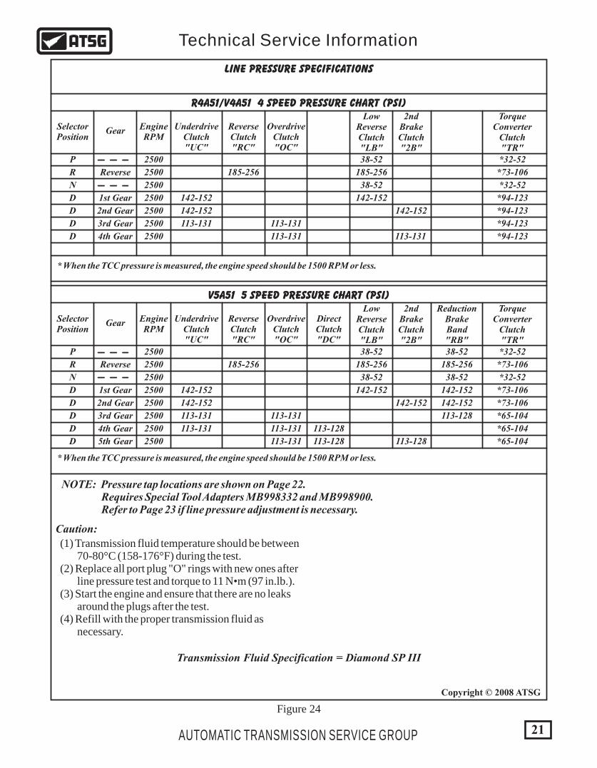
Figure 24
R4A51/V4A51 4 SPEED PRESSURE CHART (PSI)
EngineRPM
UnderdriveClutch"UC"
OverdriveClutch"OC"
LowReverseClutch"LB"
2ndBrakeClutch"2B"
TorqueConverter
Clutch"TR"
ReverseClutch"RC"
SelectorPosition
Gear
Reverse
1st Gear
2500
2500
2500
2500 142-152
38-52
185-256
38-52
142-152
*32-52
*73-106
*32-52
*94-123
185-256
P
R
N
D
4th Gear 2500 *94-123113-131 113-131D
3rd Gear 2500 113-131 *94-123113-131D
2nd Gear 2500 142-152 142-152 *94-123D
* When the TCC pressure is measured, the engine speed should be 1500 RPM or less.
V5A51 5 SPEED PRESSURE CHART (PSI)
EngineRPM
UnderdriveClutch"UC"
OverdriveClutch"OC"
DirectClutch"DC"
LowReverseClutch"LB"
2ndBrakeClutch"2B"
ReductionBrakeBand"RB"
TorqueConverter
Clutch"TR"
ReverseClutch"RC"
SelectorPosition
Gear
Reverse
1st Gear
2500
2500
2500
2500 142-152
38-52
185-256
38-52
142-152
38-52
185-256
38-52
142-152
*32-52
*73-106
*32-52
*73-106
185-256
P
R
N
D
5th Gear 2500 113-128 *65-104113-131 113-128D
4th Gear 2500 113-131 *65-104113-131 113-128D
3rd Gear 2500 113-131 113-128 *65-104113-131D
2nd Gear 2500 142-152 142-152 142-152 *73-106D
* When the TCC pressure is measured, the engine speed should be 1500 RPM or less.
LINE PRESSURE SPECIFICATIONS
NOTE: Pressure tap locations are shown on Page 22. Requires Special Tool Adapters MB998332 and MB998900. Refer to Page 23 if line pressure adjustment is necessary.
Caution:
(1) Transmission fluid temperature should be between 70-80°C (158-176°F) during the test. (2) Replace all port plug "O" rings with new ones after line pressure test and torque to 11 N•m (97 in.lb.). (3) Start the engine and ensure that there are no leaks around the plugs after the test. (4) Refill with the proper transmission fluid as necessary.
Transmission Fluid Specification = Diamond SP III
21
Copyright © 2008 ATSG
AUTOMATIC TRANSMISSION SERVICE GROUP
Technical Service Information
TR
TA
LB UCOC 2B
RC
B 223
RB DC
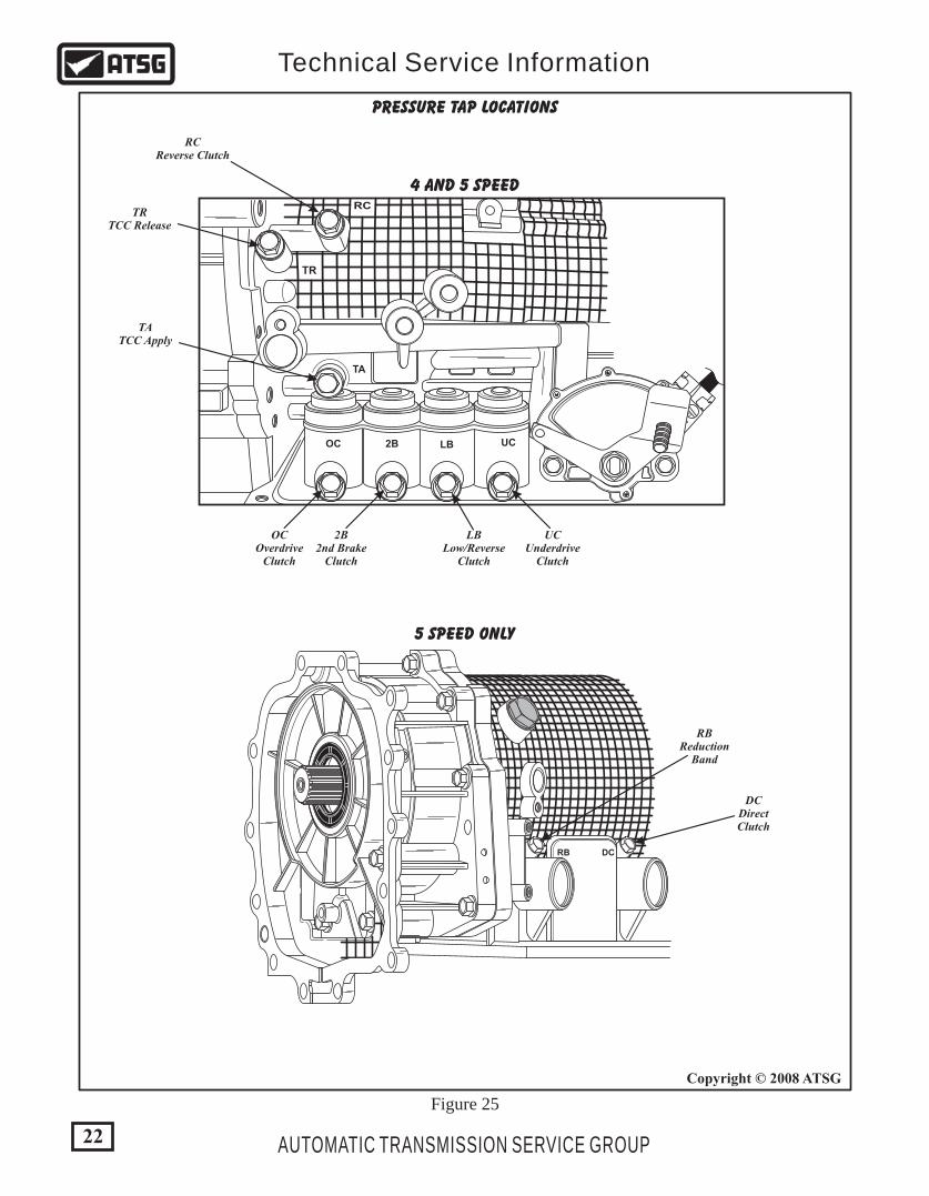
PRESSURE TAP LOCATIONS
4 AND 5 SPEED
5 SPEED ONLY
RCReverse Clutch
TRTCC Release
TATCC Apply
OCOverdrive
Clutch
UCUnderdrive
Clutch
DCDirectClutch
RBReduction
Band
LBLow/Reverse
Clutch
2B2nd Brake
Clutch
22
Copyright © 2008 ATSG
AUTOMATIC TRANSMISSION SERVICE GROUP
Technical Service Information
Figure 25

23
Copyright © 2008 ATSG
AUTOMATIC TRANSMISSION SERVICE GROUP
Technical Service Information
372
180X
302 MANUAL VALVE SLIDER 336 MANUAL VALVE
302
336
Line Pressure Adjusting Screw
ADJUSTING LINE PRESSUREAdjustment Procedure
1. Drain the transmission fluid. Note: Pressure test must be performed before attempting any adjustments. 2. Remove the transmission oil pan. 3. Turn the adjusting screw shown in Figure 26 to adjust line pressure to the nominal value. The pressure increases when the screw is turned counter-clockwise. Note: Adjust to the middle of the nominal range when transmission is in "D" position. Nominal line pressure is 142-152 PSI. Each complete turn of the adjusting screw changes pressure 5.1 PSI. 4. Install the transmission pan and transmission fluid. 5. Repeat the line pressure test, and re-adjust the line pressure as necessary.
Figure 26
B 2
SAFETY PRECAUTIONS
EXTERNAL COMPONENTS
TRANSMISSION DISASSEMBLY
Service information provided in this manual by ATSG is intended for use by professional, qualified technicians. Attempting repairs or service without the appropriate training, tools and equipment could cause injury to you or others. The service procedures we recommend and describe in this manual are effective methods of performing service and repair on this unit. Some of the procedures require the use of special tools that are designed for specific purposes. This manual contains CAUTIONS that you must observe carefully in order to reduce the risk of injury to yourself or others. This manual also contains NOTES that must be carefully followed in order to avoid improper service that may damage the vehicle, tools and/or equipment.
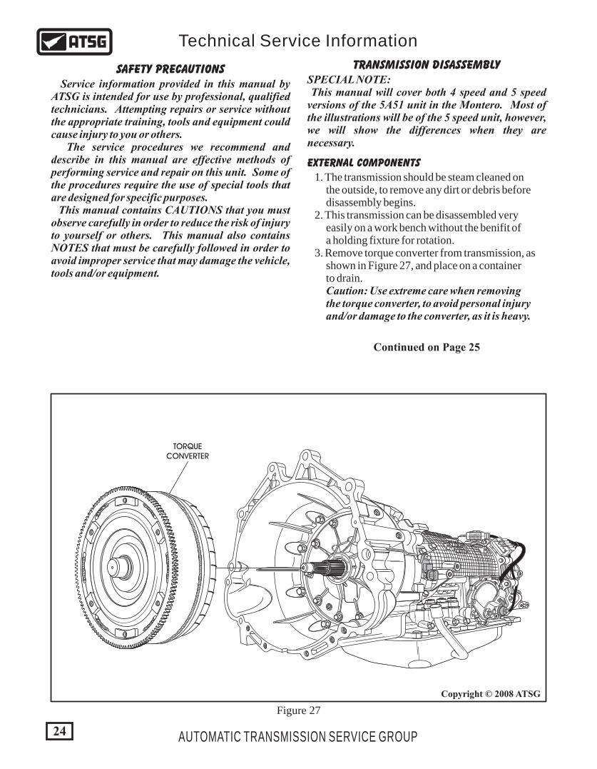
TORQUECONVERTER
1. The transmission should be steam cleaned on the outside, to remove any dirt or debris before disassembly begins. 2. This transmission can be disassembled very easily on a work bench without the benifit of a holding fixture for rotation. 3. Remove torque converter from transmission, as shown in Figure 27, and place on a container to drain. Caution: Use extreme care when removing the torque converter, to avoid personal injury and/or damage to the converter, as it is heavy.
24
Copyright © 2008 ATSG
AUTOMATIC TRANSMISSION SERVICE GROUP
Technical Service Information
Continued on Page 25
Figure 27
SPECIAL NOTE: This manual will cover both 4 speed and 5 speed versions of the 5A51 unit in the Montero. Most of the illustrations will be of the 5 speed unit, however, we will show the differences when they are necessary.
25
Copyright © 2008 ATSG
Copyright © 2008 ATSG
AUTOMATIC TRANSMISSION SERVICE GROUP
Technical Service Information
EXTERNAL COMPONENTS (CONT'D)TRANSMISSION DISASSEMBLY
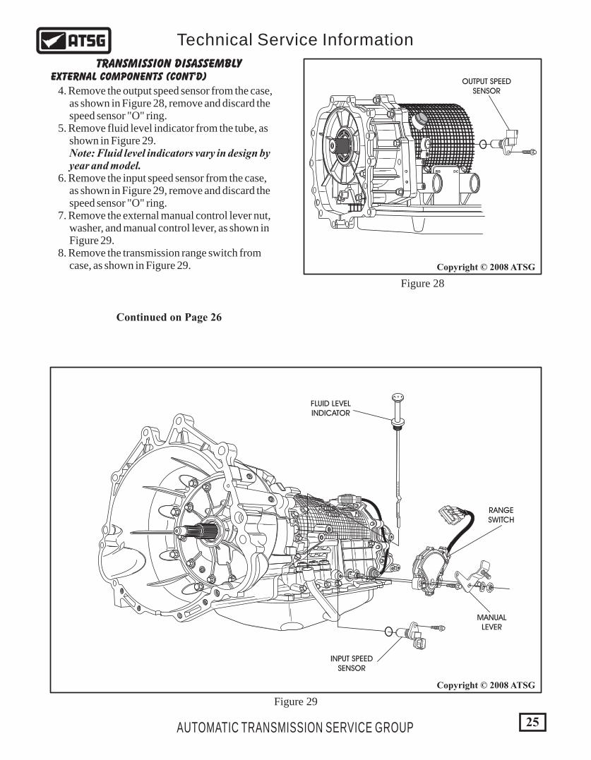
4. Remove the output speed sensor from the case, as shown in Figure 28, remove and discard the speed sensor "O" ring. 5. Remove fluid level indicator from the tube, as shown in Figure 29. Note: Fluid level indicators vary in design by year and model. 6. Remove the input speed sensor from the case, as shown in Figure 29, remove and discard the speed sensor "O" ring. 7. Remove the external manual control lever nut, washer, and manual control lever, as shown in Figure 29. 8. Remove the transmission range switch from case, as shown in Figure 29.
B 2
FLUID LEVELINDICATOR
INPUT SPEEDSENSOR
OUTPUT SPEEDSENSOR
RANGESWITCH
MANUALLEVER
HO
TA
DJU
ST A
T H
OT
A T F
RB DC
Figure 28
Figure 29
Continued on Page 26

EXTERNAL COMPONENTS (CONT'D)TRANSMISSION DISASSEMBLY
9. Remove the 4WD adapter housing, as shown in Figure 30, or the 2WD extension housing. Both are similar in their removal, and bolt locations and lengths are the same on both versions. Note: Exploded views of both versions are shown in Figure 32 and 33. 10. Set the adapter housing, or extension housing aside for component rebuild.
11. Remove the parking gear snap ring from the output shaft, as shown in Figure 31. 12. Remove the parking gear using a puller that is capable of 2200 pounds. Note: There are two versions of the parking gear. One that uses a "heat shrink" process for installation and one that does not. Two ID grooves is the normal type and three ID grooves is the shrink fit type. 13. Some parking gears may be removed without using a puller.
Continued on Page 28
572
575
574
572 4WD ADAPTER HOUSING. 574 35MM (1.378") ADAPTER HOUSING BOLT (8 REQUIRED). 575 90MM (3.543") ADAPTER HOUSING BOLT (3 REQUIRED).
570
571
ID GROOVESFACE
REARWARD
570 PARKING GEAR. 571 PARKING GEAR RETAINING SNAP RING.
Figure 30 Figure 31
26
Copyright © 2008 ATSGCopyright © 2008 ATSG
AUTOMATIC TRANSMISSION SERVICE GROUP
Technical Service Information
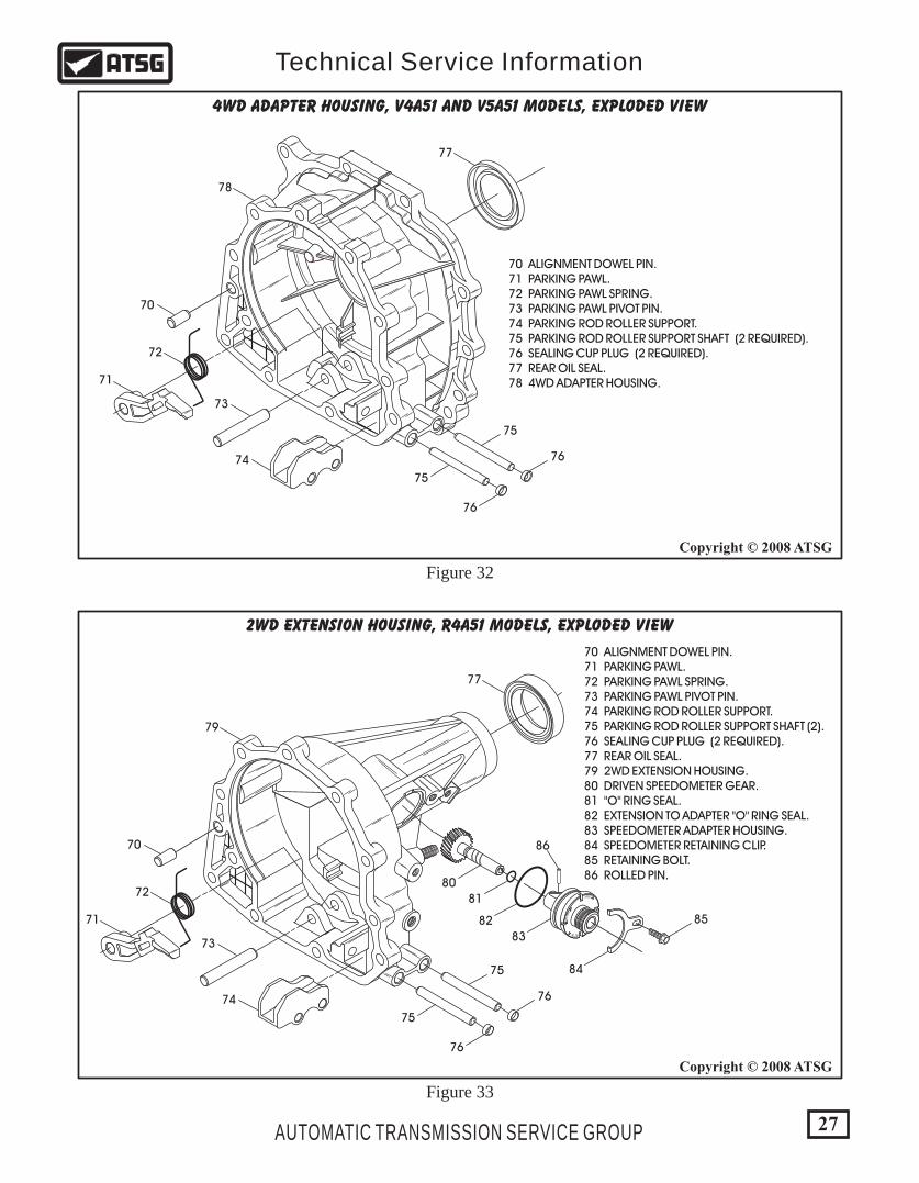
Figure 33
Figure 32
4WD ADAPTER HOUSING, V4A51 AND V5A51 MODELS, EXPLODED VIEW
2WD EXTENSION HOUSING, R4A51 MODELS, EXPLODED VIEW
70
71
72
73
74
75
76
75
76
77
78
70 ALIGNMENT DOWEL PIN. 71 PARKING PAWL. 72 PARKING PAWL SPRING. 73 PARKING PAWL PIVOT PIN. 74 PARKING ROD ROLLER SUPPORT. 75 PARKING ROD ROLLER SUPPORT SHAFT (2). 76 SEALING CUP PLUG (2 REQUIRED). 77 REAR OIL SEAL. 79 2WD EXTENSION HOUSING. 80 DRIVEN SPEEDOMETER GEAR. 81 "O" RING SEAL. 82 EXTENSION TO ADAPTER "O" RING SEAL. 83 SPEEDOMETER ADAPTER HOUSING. 84 SPEEDOMETER RETAINING CLIP. 85 RETAINING BOLT. 86 ROLLED PIN.
70 ALIGNMENT DOWEL PIN. 71 PARKING PAWL. 72 PARKING PAWL SPRING. 73 PARKING PAWL PIVOT PIN. 74 PARKING ROD ROLLER SUPPORT. 75 PARKING ROD ROLLER SUPPORT SHAFT (2 REQUIRED). 76 SEALING CUP PLUG (2 REQUIRED). 77 REAR OIL SEAL. 78 4WD ADAPTER HOUSING.
70
71
72
73
74
75
76
75
80
81
82
83
84
85
86
76
77
79
20-2
2
13-
92
82-62
23-25
27
Copyright © 2008 ATSG
Copyright © 2008 ATSG
AUTOMATIC TRANSMISSION SERVICE GROUP
Technical Service Information
28
Copyright © 2008 ATSG
AUTOMATIC TRANSMISSION SERVICE GROUP
Technical Service Information
INTERNAL COMPONENTSTRANSMISSION DISASSEMBLY
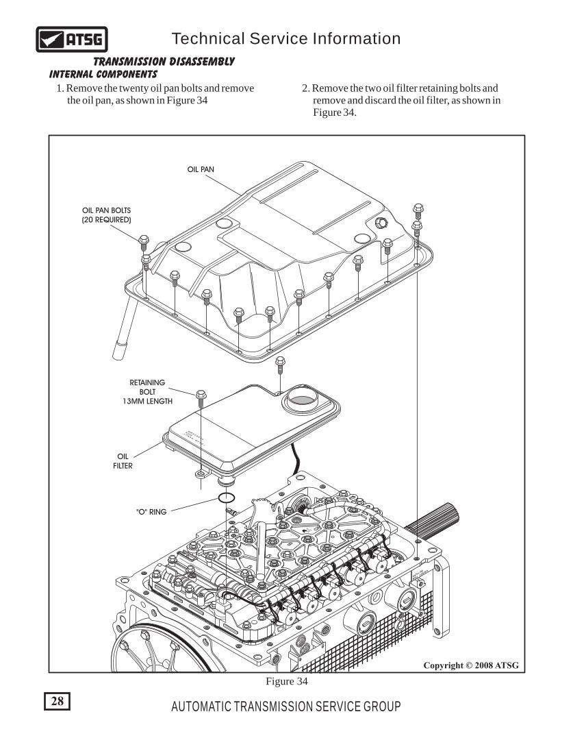
1. Remove the twenty oil pan bolts and remove the oil pan, as shown in Figure 34
2. Remove the two oil filter retaining bolts and remove and discard the oil filter, as shown in Figure 34.
6 00
6 00
1010
V5A51 7AB
BL7430
180X
6
00
- 2777
>PA
66 - G
F 30
<
NO
K
MR
52
88
36
Figure 34
RETAININGBOLT
13MM LENGTH
OILFILTER
OIL PAN
OIL PAN BOLTS(20 REQUIRED)
"O" RING
6 00
6 00
1010
V5A51 7AB
BL7430
180X
6
00
- 2777
Figure 35
29
Copyright © 2008 ATSG
AUTOMATIC TRANSMISSION SERVICE GROUP
Technical Service Information
TFTSENSOR
DETENTSPRING
DISCONNECTEDWIRE HARNESS
RETAININGBOLT
25MM LENGTH
RETAININGBOLT
10MM LENGTH
"O" RINGSEAL
INTERNAL COMPONENTS (CONT'D)TRANSMISSION DISASSEMBLY
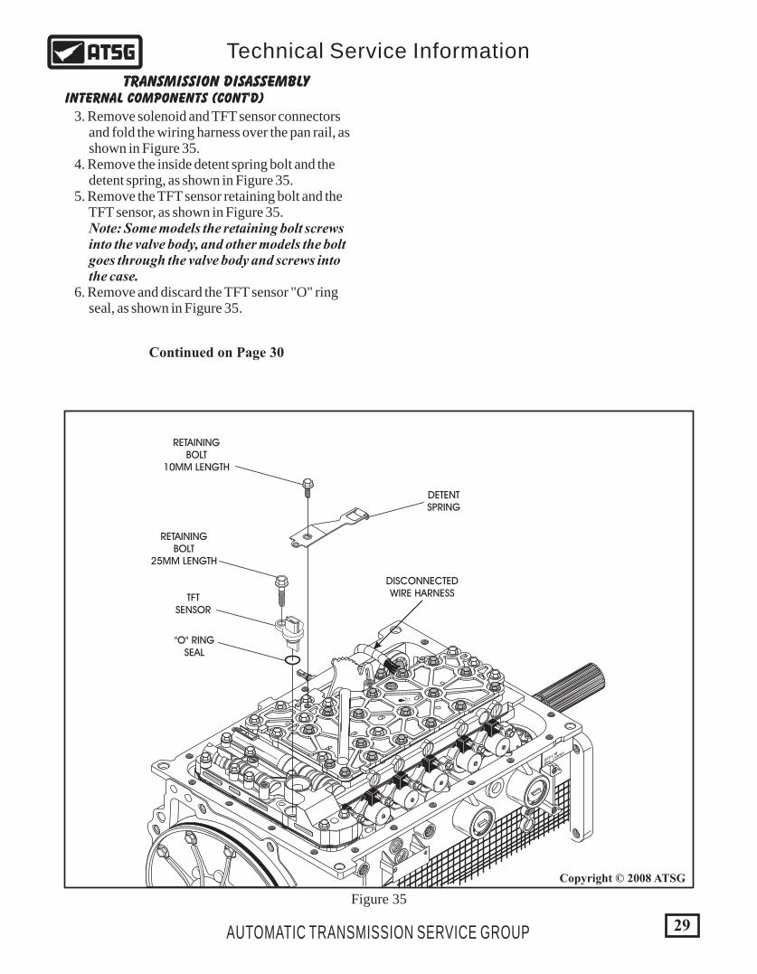
3. Remove solenoid and TFT sensor connectors and fold the wiring harness over the pan rail, as shown in Figure 35. 4. Remove the inside detent spring bolt and the detent spring, as shown in Figure 35. 5. Remove the TFT sensor retaining bolt and the TFT sensor, as shown in Figure 35. Note: Some models the retaining bolt screws into the valve body, and other models the bolt goes through the valve body and screws into the case. 6. Remove and discard the TFT sensor "O" ring seal, as shown in Figure 35.
Continued on Page 30
6 00
6 00
1010
V5A51 7AB
BL7430
180X
6
00
- 2777
368
368
36
36
36
5 SPEEDONLY
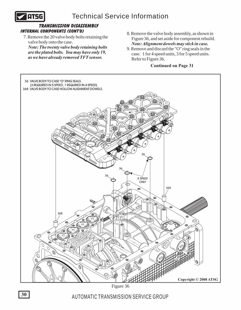
36 VALVE BODY TO CASE "O" RING SEALS. (3 REQUIRED IN 5 SPEED, 1 REQUIRED IN 4 SPEED) 368 VALVE BODY TO CASE HOLLOW ALIGNMENT DOWELS.
INTERNAL COMPONENTS (CONT'D)TRANSMISSION DISASSEMBLY
7. Remove the 20 valve body bolts retaining the valve body onto the case. Note: The twenty valve body retaining bolts are the plated bolts. You may have only 19, as we have already removed TFT sensor.
8. Remove the valve body assembly, as shown in Figure 36, and set aside for component rebuild. Note: Alignment dowels may stick in case. 9. Remove and discard the "O" ring seals in the case. 1 for 4 speed units, 3 for 5 speed units. Refer to Figure 36.
Continued on Page 31
30
Copyright © 2008 ATSG
AUTOMATIC TRANSMISSION SERVICE GROUP
Technical Service Information
Figure 36
31
Copyright © 2008 ATSG
Copyright © 2008 ATSG
AUTOMATIC TRANSMISSION SERVICE GROUP
Technical Service Information
INTERNAL COMPONENTS (CONT'D)TRANSMISSION DISASSEMBLY
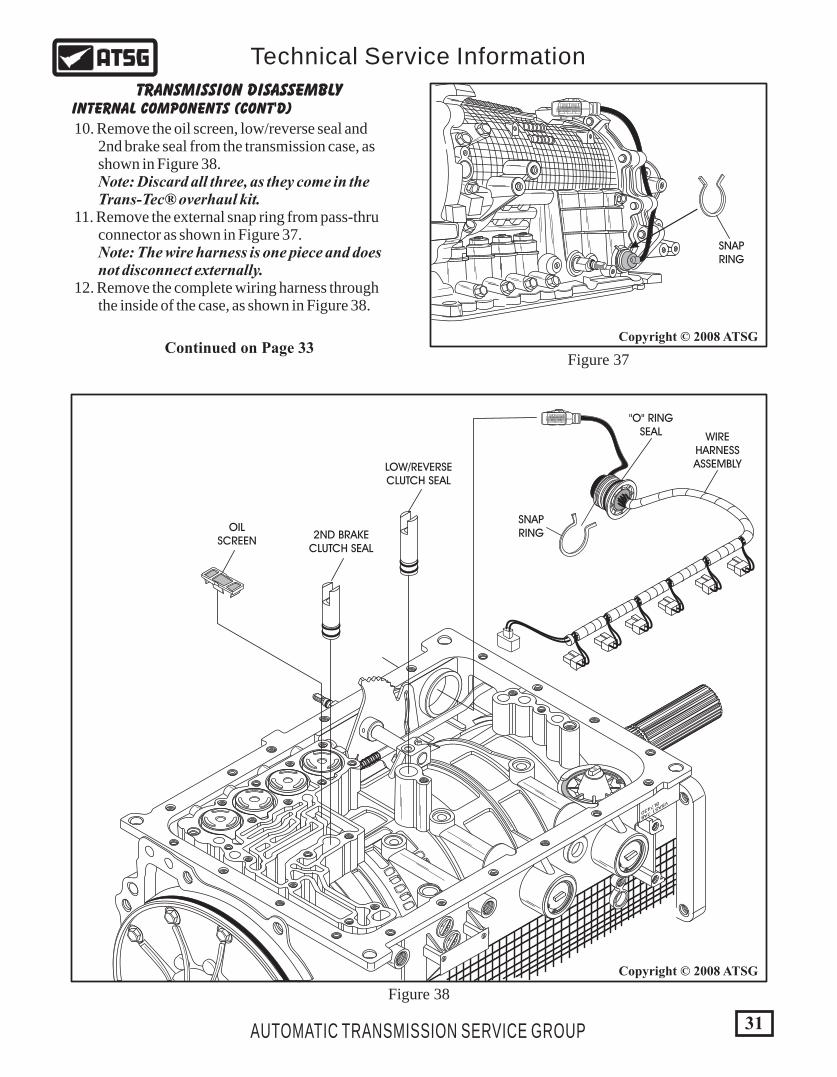
10. Remove the oil screen, low/reverse seal and 2nd brake seal from the transmission case, as shown in Figure 38. Note: Discard all three, as they come in the Trans-Tec® overhaul kit. 11. Remove the external snap ring from pass-thru connector as shown in Figure 37. Note: The wire harness is one piece and does not disconnect externally. 12. Remove the complete wiring harness through the inside of the case, as shown in Figure 38.
6 00
6 00
1010
V5A51 7AB
BL7430
WIREHARNESSASSEMBLY
"O" RINGSEAL
SNAPRING
SNAPRING
LOW/REVERSECLUTCH SEAL
OILSCREEN
2ND BRAKECLUTCH SEAL
Figure 37
Figure 38
Continued on Page 33

32
Copyright © 2008 ATSG
AUTOMATIC TRANSMISSION SERVICE GROUP
Technical Service Information
6 00
6 00
1010
V5A51 7AB
BL7430
16
15
19
22
20
23
25
26
27
32
33
34
35
36
5 SPEEDONLY
28
29
29
30
31
15
15
17
18
21
24
15 ACCUMULATOR PISTON SCARF-CUT SEAL (ALL, 6 REQUIRED) 16 OVERDRIVE CLUTCH ACCUMULATOR PISTON 17 OVERDRIVE CLUTCH ACCUMULATOR OUTER SPRING 18 2ND BRAKE CLUTCH ACCUMULATOR PISTON 19 2ND BRAKE CLUTCH ACCUMULATOR OUTER SPRING 20 2ND BRAKE CLUTCH ACCUMULATOR INNER SPRING 21 LOW/REVERSE CLUTCH ACCUMULATOR PISTON 22 LOW/REVERSE CLUTCH ACCUMULATOR OUTER SPRING 23 LOW/REVERSE CLUTCH ACCUMULATOR INNER SPRING 24 UNDERDRIVE CLUTCH ACCUMULATOR PISTON 25 UNDERDRIVE CLUTCH ACCUMULATOR OUTER SPRING 26 UNDERDRIVE CLUTCH ACCUMULATOR INNER SPRING 27 DIRECT CLUTCH ACCUMULATOR COVER SNAP RING 28 DIRECT CLUTCH ACCUMULATOR COVER 29 ACCUMULATOR COVER "O" RING SEAL (2 REQUIRED) 30 DIRECT CLUTCH ACCUMULATOR SPRING 31 DIRECT CLUTCH ACCUMULATOR PISTON 32 REDUCTION BAND ACCUMULATOR COVER SNAP RING 33 REDUCTION BAND ACCUMULATOR COVER 34 REDUCTION BAND ACCUMULATOR SPRING 35 REDUCTION BAND ACCUMULATOR PISTON 36 VALVE BODY TO CASE "O" RING SEAL (3 REQUIRED IN 5 SPEED, 1 REQUIRED IN 4 SPEED)
ACCUMULATOR PISTON AND SPRING LOCATIONS EXPLODED VIEW
Figure 39
1010
V5A51 7AB
BL7430
1010
40
41
42
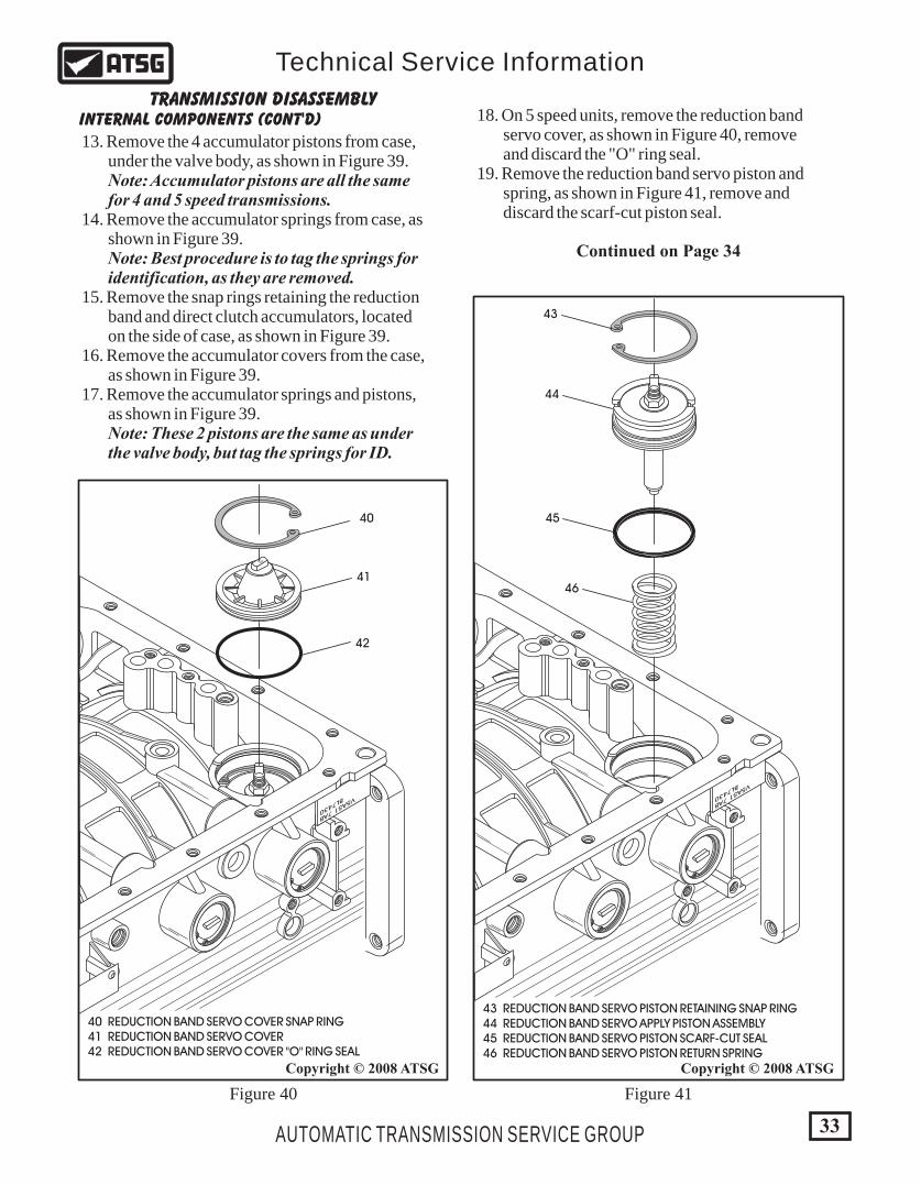
40 REDUCTION BAND SERVO COVER SNAP RING 41 REDUCTION BAND SERVO COVER 42 REDUCTION BAND SERVO COVER "O" RING SEAL
33
Copyright © 2008 ATSG Copyright © 2008 ATSG
AUTOMATIC TRANSMISSION SERVICE GROUP
Technical Service Information
INTERNAL COMPONENTS (CONT'D)TRANSMISSION DISASSEMBLY
13. Remove the 4 accumulator pistons from case, under the valve body, as shown in Figure 39. Note: Accumulator pistons are all the same for 4 and 5 speed transmissions. 14. Remove the accumulator springs from case, as shown in Figure 39. Note: Best procedure is to tag the springs for identification, as they are removed. 15. Remove the snap rings retaining the reduction band and direct clutch accumulators, located on the side of case, as shown in Figure 39. 16. Remove the accumulator covers from the case, as shown in Figure 39. 17. Remove the accumulator springs and pistons, as shown in Figure 39. Note: These 2 pistons are the same as under the valve body, but tag the springs for ID.
Continued on Page 34
1010
V5A51 7AB
BL7430
43
44
45
46
43 REDUCTION BAND SERVO PISTON RETAINING SNAP RING 44 REDUCTION BAND SERVO APPLY PISTON ASSEMBLY 45 REDUCTION BAND SERVO PISTON SCARF-CUT SEAL 46 REDUCTION BAND SERVO PISTON RETURN SPRING
18. On 5 speed units, remove the reduction band servo cover, as shown in Figure 40, remove and discard the "O" ring seal. 19. Remove the reduction band servo piston and spring, as shown in Figure 41, remove and discard the scarf-cut piston seal.
Figure 40 Figure 41
INTERNAL COMPONENTS (CONT'D)TRANSMISSION DISASSEMBLY
Continued on Page 35
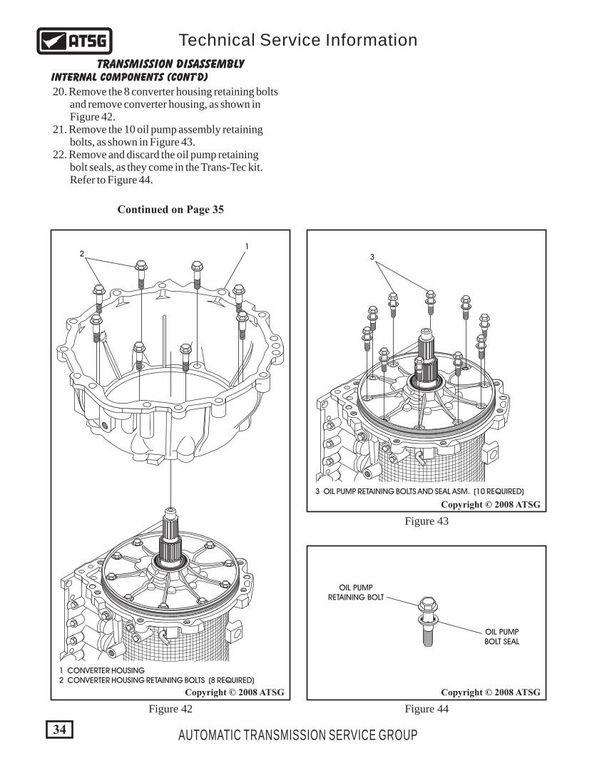
20. Remove the 8 converter housing retaining bolts and remove converter housing, as shown in Figure 42. 21. Remove the 10 oil pump assembly retaining bolts, as shown in Figure 43. 22. Remove and discard the oil pump retaining bolt seals, as they come in the Trans-Tec kit. Refer to Figure 44.
34
Copyright © 2008 ATSG
Copyright © 2008 ATSG
Copyright © 2008 ATSG
AUTOMATIC TRANSMISSION SERVICE GROUP
Technical Service Information
12
1 CONVERTER HOUSING 2 CONVERTER HOUSING RETAINING BOLTS (8 REQUIRED)
3
OIL PUMPRETAINING BOLT
OIL PUMPBOLT SEAL
3 OIL PUMP RETAINING BOLTS AND SEAL ASM. (10 REQUIRED)
Figure 42 Figure 44
Figure 43
35
Copyright © 2008 ATSG
AUTOMATIC TRANSMISSION SERVICE GROUP
Technical Service Information
MITSUBISHIMD998333
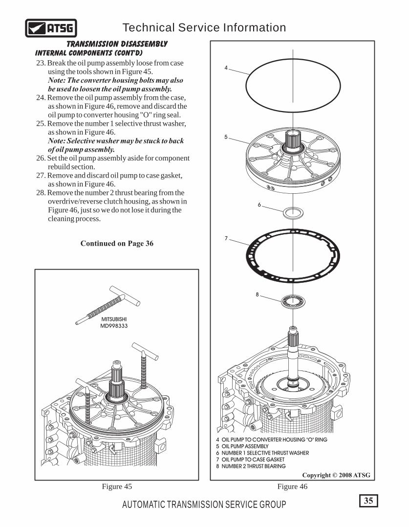
4 OIL PUMP TO CONVERTER HOUSING "O" RING 5 OIL PUMP ASSEMBLY 6 NUMBER 1 SELECTIVE THRUST WASHER 7 OIL PUMP TO CASE GASKET 8 NUMBER 2 THRUST BEARING
4
5
6
7
8
Figure 45 Figure 46
INTERNAL COMPONENTS (CONT'D)TRANSMISSION DISASSEMBLY
Continued on Page 36
23. Break the oil pump assembly loose from case using the tools shown in Figure 45. Note: The converter housing bolts may also be used to loosen the oil pump assembly. 24. Remove the oil pump assembly from the case, as shown in Figure 46, remove and discard the oil pump to converter housing "O" ring seal. 25. Remove the number 1 selective thrust washer, as shown in Figure 46. Note: Selective washer may be stuck to back of oil pump assembly. 26. Set the oil pump assembly aside for component rebuild section. 27. Remove and discard oil pump to case gasket, as shown in Figure 46. 28. Remove the number 2 thrust bearing from the overdrive/reverse clutch housing, as shown in Figure 46, just so we do not lose it during the cleaning process.
INTERNAL COMPONENTS (CONT'D)TRANSMISSION DISASSEMBLY
Continued on Page 37
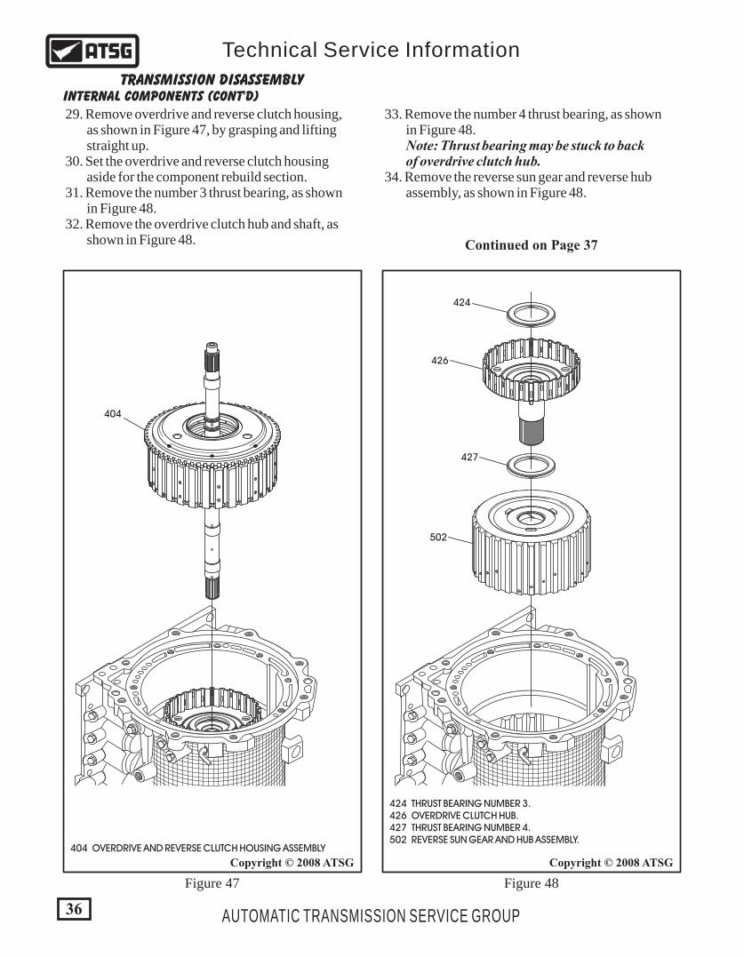
29. Remove overdrive and reverse clutch housing, as shown in Figure 47, by grasping and lifting straight up. 30. Set the overdrive and reverse clutch housing aside for the component rebuild section. 31. Remove the number 3 thrust bearing, as shown in Figure 48. 32. Remove the overdrive clutch hub and shaft, as shown in Figure 48.
33. Remove the number 4 thrust bearing, as shown in Figure 48. Note: Thrust bearing may be stuck to back of overdrive clutch hub. 34. Remove the reverse sun gear and reverse hub assembly, as shown in Figure 48.
404 OVERDRIVE AND REVERSE CLUTCH HOUSING ASSEMBLY
424
426
427
502
404
36
Copyright © 2008 ATSGCopyright © 2008 ATSG
AUTOMATIC TRANSMISSION SERVICE GROUP
Technical Service Information
Figure 47 Figure 48
424 THRUST BEARING NUMBER 3. 426 OVERDRIVE CLUTCH HUB. 427 THRUST BEARING NUMBER 4. 502 REVERSE SUN GEAR AND HUB ASSEMBLY.
509
510
428
429
433
434
436
435437
C
37
Copyright © 2008 ATSGCopyright © 2008 ATSG
AUTOMATIC TRANSMISSION SERVICE GROUP
Technical Service Information
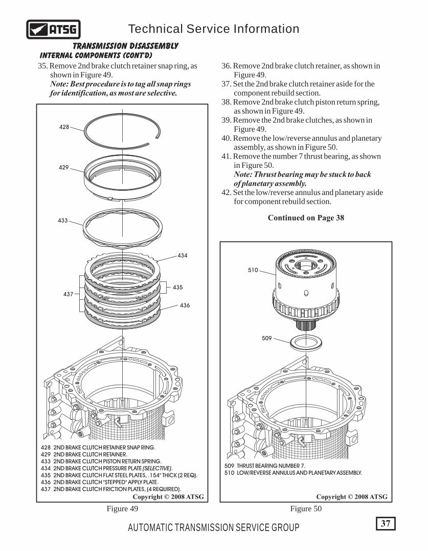
428 2ND BRAKE CLUTCH RETAINER SNAP RING. 429 2ND BRAKE CLUTCH RETAINER. 433 2ND BRAKE CLUTCH PISTON RETURN SPRING. 434 2ND BRAKE CLUTCH PRESSURE PLATE (SELECTIVE). 435 2ND BRAKE CLUTCH FLAT STEEL PLATES, .154" THICK (2 REQ). 436 2ND BRAKE CLUTCH "STEPPED" APPLY PLATE. 437 2ND BRAKE CLUTCH FRICTION PLATES, (4 REQUIRED).
Figure 49 Figure 50
INTERNAL COMPONENTS (CONT'D)TRANSMISSION DISASSEMBLY
35. Remove 2nd brake clutch retainer snap ring, as shown in Figure 49. Note: Best procedure is to tag all snap rings for identification, as most are selective.
36. Remove 2nd brake clutch retainer, as shown in Figure 49. 37. Set the 2nd brake clutch retainer aside for the component rebuild section. 38. Remove 2nd brake clutch piston return spring, as shown in Figure 49. 39. Remove the 2nd brake clutches, as shown in Figure 49. 40. Remove the low/reverse annulus and planetary assembly, as shown in Figure 50. 41. Remove the number 7 thrust bearing, as shown in Figure 50. Note: Thrust bearing may be stuck to back of planetary assembly. 42. Set the low/reverse annulus and planetary aside for component rebuild section.
509 THRUST BEARING NUMBER 7. 510 LOW/REVERSE ANNULUS AND PLANETARY ASSEMBLY.
Continued on Page 38
B
438
441
443
444
439
440
442
38
Copyright © 2008 ATSGCopyright © 2008 ATSG
AUTOMATIC TRANSMISSION SERVICE GROUP
Technical Service Information
Figure 51 Figure 52
INTERNAL COMPONENTS (CONT'D)TRANSMISSION DISASSEMBLY
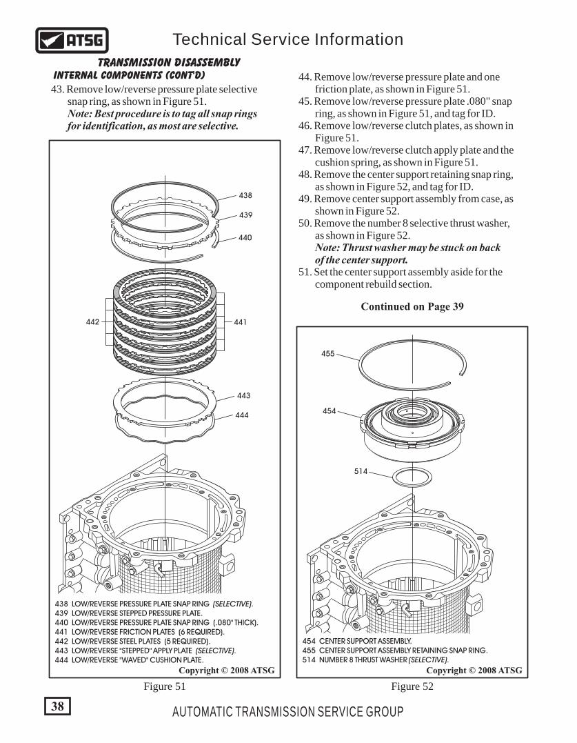
44. Remove low/reverse pressure plate and one friction plate, as shown in Figure 51. 45. Remove low/reverse pressure plate .080" snap ring, as shown in Figure 51, and tag for ID. 46. Remove low/reverse clutch plates, as shown in Figure 51. 47. Remove low/reverse clutch apply plate and the cushion spring, as shown in Figure 51. 48. Remove the center support retaining snap ring, as shown in Figure 52, and tag for ID. 49. Remove center support assembly from case, as shown in Figure 52. 50. Remove the number 8 selective thrust washer, as shown in Figure 52. Note: Thrust washer may be stuck on back of the center support. 51. Set the center support assembly aside for the component rebuild section.
Continued on Page 39
43. Remove low/reverse pressure plate selective snap ring, as shown in Figure 51. Note: Best procedure is to tag all snap rings for identification, as most are selective.
454 CENTER SUPPORT ASSEMBLY. 455 CENTER SUPPORT ASSEMBLY RETAINING SNAP RING. 514 NUMBER 8 THRUST WASHER (SELECTIVE).
514
454
455
438 LOW/REVERSE PRESSURE PLATE SNAP RING (SELECTIVE). 439 LOW/REVERSE STEPPED PRESSURE PLATE. 440 LOW/REVERSE PRESSURE PLATE SNAP RING (.080" THICK). 441 LOW/REVERSE FRICTION PLATES (6 REQUIRED). 442 LOW/REVERSE STEEL PLATES (5 REQUIRED). 443 LOW/REVERSE "STEPPED" APPLY PLATE (SELECTIVE). 444 LOW/REVERSE "WAVED" CUSHION PLATE.

39
Copyright © 2008 ATSG
AUTOMATIC TRANSMISSION SERVICE GROUP
Technical Service Information
"4 SPEED" INTERNAL COMPONENTS (CONT'D)TRANSMISSION DISASSEMBLY
After the center support has been removed, the disassembly process changes between the 4 speed and 5 speed units. This of course is because of the added reduction planetary, reduction band, direct clutch and direct sprag, all in the rear of case.
We will begin here with the 4 speed disassembly below the center support, as shown in Figure 53. The 5 speed disassembly below the center support begins on Page 42.
514 NUMBER 8 THRUST WASHER (SELECTIVE REAR END-PLAY). 515 NUMBER 9 THRUST BEARING. 517 REDUCTION RING GEAR OUTPUT FLANGE. 518 NUMBER 10 THRUST BEARING. 519 UNDERDRIVE CLUTCH HUB. 520 NUMBER 11 THRUST BEARING. 533 COMPLETE UNDERDRIVE CLUTCH HOUSING ASSEMBLY. 535 NUMBER 12 THRUST BEARING. 536 UNDERDRIVE CLUTCH BUTT-CUT TEFLON SEAL RINGS. 537 OUTPUT SHAFT BUSHING. 539 OUTPUT SHAFT STEEL HOOK-JOINT SEAL RINGS. 554 NUMBER 13 THRUST BEARING RETAINER. 555 NUMBER 13 THRUST BEARING. 556 OUTPUT SHAFT ASSEMBLY. 557 OUTPUT SHAFT SUPPORT.
517
515514
520
519
518
533
535
537
556
536539
555
557
554
4 SPEED BELOW CENTER SUPPORT EXPLODED VIEW
Continued on Page 40
Figure 53
"4 SPEED" INTERNAL COMPONENTS (CONT'D)TRANSMISSION DISASSEMBLY
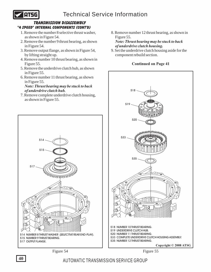
1. Remove the number 8 selective thrust washer, as shown in Figure 54. 2. Remove the number 9 thrust bearing, as shown in Figure 54. 3. Remove output flange, as shown in Figure 54, by lifting straight up. 4. Remove number 10 thrust bearing, as shown in Figure 55. 5. Remove the underdrive clutch hub, as shown in Figure 55. 6. Remove number 11 thrust bearing, as shown in Figure 55. Note: Thrust bearing may be stuck to back of underdrive clutch hub. 7. Remove complete underdrive clutch housing, as shown in Figure 55.
514
515
517
519
520
518
514 NUMBER 8 THRUST WASHER (SELECTIVE REAR END-PLAY). 515 NUMBER 9 THRUST BEARING. 517 OUTPUT FLANGE.
533
535
518 NUMBER 10 THRUST BEARING. 519 UNDERDRIVE CLUTCH HUB. 520 NUMBER 11 THRUST BEARING. 533 COMPLETE UNDERDRIVE CLUTCH HOUSING ASSEMBLY. 535 NUMBER 12 THRUST BEARING.
Figure 54 Figure 55
8. Remove number 12 thrust bearing, as shown in Figure 55. Note: Thrust bearing may be stuck to back of underdrive clutch housing. 9. Set the underdrive clutch housing aside for the component rebuild section.
Continued on Page 41
40
Copyright © 2008 ATSG
AUTOMATIC TRANSMISSION SERVICE GROUP
Technical Service Information
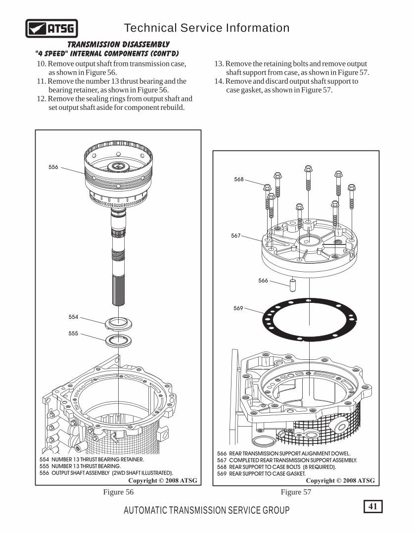
566 REAR TRANSMISSION SUPPORT ALIGNMENT DOWEL. 567 COMPLETED REAR TRANSMISSION SUPPORT ASSEMBLY. 568 REAR SUPPORT TO CASE BOLTS (8 REQUIRED). 569 REAR SUPPORT TO CASE GASKET.
568
566
567
569
555
556
554
554 NUMBER 13 THRUST BEARING RETAINER. 555 NUMBER 13 THRUST BEARING. 556 OUTPUT SHAFT ASSEMBLY (2WD SHAFT ILLUSTRATED).
Figure 56 Figure 57
41
Copyright © 2008 ATSGCopyright © 2008 ATSG
AUTOMATIC TRANSMISSION SERVICE GROUP
Technical Service Information
"4 SPEED" INTERNAL COMPONENTS (CONT'D)TRANSMISSION DISASSEMBLY
10. Remove output shaft from transmission case, as shown in Figure 56. 11. Remove the number 13 thrust bearing and the bearing retainer, as shown in Figure 56. 12. Remove the sealing rings from output shaft and set output shaft aside for component rebuild.
13. Remove the retaining bolts and remove output shaft support from case, as shown in Figure 57. 14. Remove and discard output shaft support to case gasket, as shown in Figure 57.
553
552
R
600 567
565
535537
538
536539
515
534
514
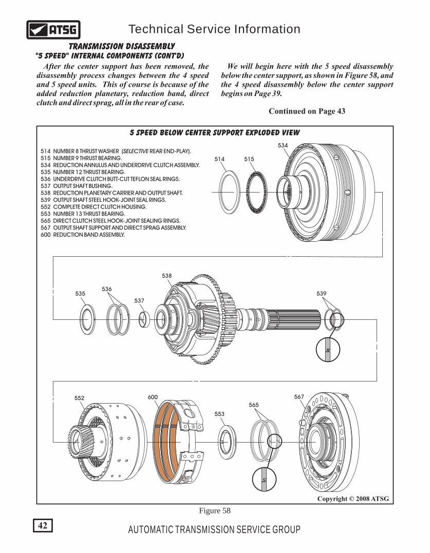
514 NUMBER 8 THRUST WASHER (SELECTIVE REAR END-PLAY). 515 NUMBER 9 THRUST BEARING. 534 REDUCTION ANNULUS AND UNDERDRIVE CLUTCH ASSEMBLY. 535 NUMBER 12 THRUST BEARING. 536 UNDERDRIVE CLUTCH BUTT-CUT TEFLON SEAL RINGS. 537 OUTPUT SHAFT BUSHING. 538 REDUCTION PLANETARY CARRIER AND OUTPUT SHAFT. 539 OUTPUT SHAFT STEEL HOOK-JOINT SEAL RINGS. 552 COMPLETE DIRECT CLUTCH HOUSING. 553 NUMBER 13 THRUST BEARING. 565 DIRECT CLUTCH STEEL HOOK-JOINT SEALING RINGS. 567 OUTPUT SHAFT SUPPORT AND DIRECT SPRAG ASSEMBLY. 600 REDUCTION BAND ASSEMBLY.
5 SPEED BELOW CENTER SUPPORT EXPLODED VIEW
"5 SPEED" INTERNAL COMPONENTS (CONT'D)TRANSMISSION DISASSEMBLY
After the center support has been removed, the disassembly process changes between the 4 speed and 5 speed units. This of course is because of the added reduction planetary, reduction band, direct clutch and direct sprag, all in the rear of case.
We will begin here with the 5 speed disassembly below the center support, as shown in Figure 58, and the 4 speed disassembly below the center support begins on Page 39.
Continued on Page 43
Figure 58
42
Copyright © 2008 ATSG
AUTOMATIC TRANSMISSION SERVICE GROUP
Technical Service Information

535
536
538
539
43
Copyright © 2008 ATSGCopyright © 2008 ATSG
AUTOMATIC TRANSMISSION SERVICE GROUP
Technical Service Information
"5 SPEED" INTERNAL COMPONENTS (CONT'D)TRANSMISSION DISASSEMBLY
1. Remove the number 8 selective thrust washer, as shown in Figure 59. 2. Remove the number 9 thrust bearing, as shown in Figure 59. 3. Remove the reduction annulus and underdrive clutch assembly, as shown in Figure 59, and set aside for the component rebuild section. 4. Remove number 12 thrust bearing, as shown in Figure 60. 5. Remove reduction planetary carrier and output shaft, as shown in Figure 60. 6. Remove and discard underdrive clutch butt-cut teflon seal rings, as shown in Figure 60. 7. Remove and discard the steel hook-joint seal rings, as shown in Figure 60.
535 NUMBER 12 THRUST BEARING. 536 UNDERDRIVE CLUTCH BUTT-CUT TEFLON SEAL RINGS. 538 REDUCTION PLANETARY CARRIER AND OUTPUT SHAFT. 539 OUTPUT SHAFT STEEL HOOK-JOINT SEAL RINGS.
514 NUMBER 8 THRUST WASHER (SELECTIVE REAR END-PLAY). 515 NUMBER 9 THRUST BEARING. 534 REDUCTION ANNULUS AND UNDERDRIVE CLUTCH ASSEMBLY.
515
534
514
Figure 59 Figure 60
Continued on Page 44

566 REAR TRANSMISSION SUPPORT ALIGNMENT DOWEL. 567 OUTPUT SHAFT SUPPORT AND DIRECT SPRAG ASSEMBLY. 568 REAR SUPPORT TO CASE BOLTS (8 REQUIRED). 569 REAR SUPPORT TO CASE GASKET.
568
566
567
569
R
"5 SPEED" INTERNAL COMPONENTS (CONT'D)TRANSMISSION DISASSEMBLY
8. Remove the complete direct clutch housing, as shown in Figure 61, and set the drum aside for the component rebuild section. 9. Remove number 13 thrust bearing, as shown in Figure 61. Note: Thrust bearing may be stuck to back of the direct clutch housing. 10. Remove the reduction band assembly from the case, as shown in Figure 61. 11. Remove the eight retaining bolts holding the output shaft support, as shown in Figure 62.
12. Remove output shaft support and direct sprag assembly, as shown in Figure 62, and set aside for the component rebuild section. 13. Remove and discard output shaft support to case gasket, as shown in Figure 62.
Figure 61 Figure 62
Disassembly Complete
44
Copyright © 2008 ATSGCopyright © 2008 ATSG
AUTOMATIC TRANSMISSION SERVICE GROUP
Technical Service Information
552
600
553
552 COMPLETE DIRECT CLUTCH HOUSING. 553 NUMBER 13 THRUST BEARING. 600 REDUCTION BAND ASSEMBLY.
6 00
6 00
1010
V5A51 7AB
BL7430
45AUTOMATIC TRANSMISSION SERVICE GROUP
Technical Service Information
COMPONENT REBUILD
Copyright © 2008 ATSG
TRANSMISSION CASE ASSEMBLY
10
5253
54
55
58
56
57
PARKING LINKAGE AND RELATED PARTS EXPLODED VIEW
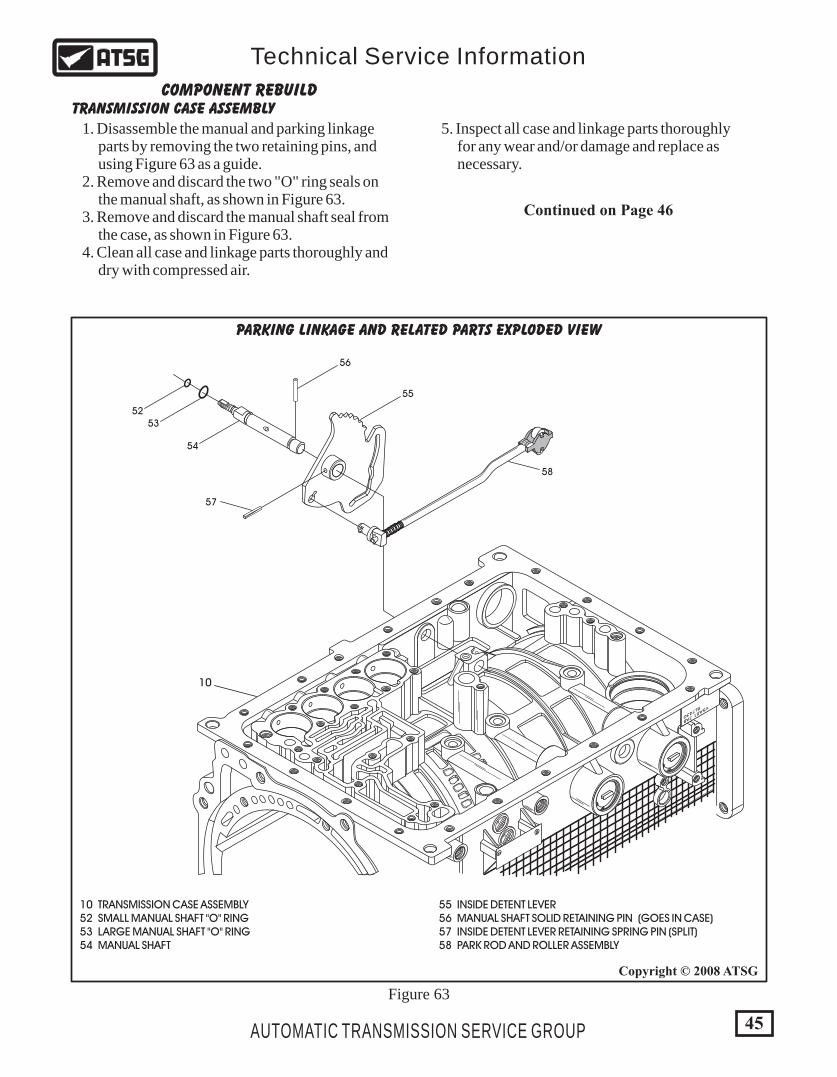
1. Disassemble the manual and parking linkage parts by removing the two retaining pins, and using Figure 63 as a guide. 2. Remove and discard the two "O" ring seals on the manual shaft, as shown in Figure 63. 3. Remove and discard the manual shaft seal from the case, as shown in Figure 63. 4. Clean all case and linkage parts thoroughly and dry with compressed air.
5. Inspect all case and linkage parts thoroughly for any wear and/or damage and replace as necessary.
Figure 63
Continued on Page 46
10 TRANSMISSION CASE ASSEMBLY 52 SMALL MANUAL SHAFT "O" RING 53 LARGE MANUAL SHAFT "O" RING 54 MANUAL SHAFT
55 INSIDE DETENT LEVER 56 MANUAL SHAFT SOLID RETAINING PIN (GOES IN CASE) 57 INSIDE DETENT LEVER RETAINING SPRING PIN (SPLIT) 58 PARK ROD AND ROLLER ASSEMBLY
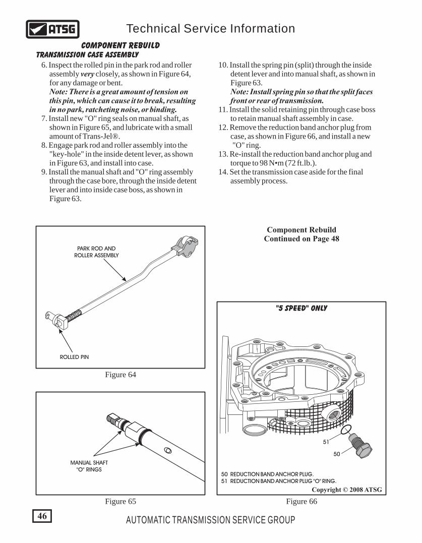
MANUAL SHAFT"O" RINGS
ROLLED PIN
PARK ROD ANDROLLER ASSEMBLY
50
51
COMPONENT REBUILD
"5 SPEED" ONLY
TRANSMISSION CASE ASSEMBLY
6. Inspect the rolled pin in the park rod and roller assembly very closely, as shown in Figure 64, for any damage or bent. Note: There is a great amount of tension on this pin, which can cause it to break, resulting in no park, ratcheting noise, or binding. 7. Install new "O" ring seals on manual shaft, as shown in Figure 65, and lubricate with a small amount of Trans-Jel®. 8. Engage park rod and roller assembly into the "key-hole" in the inside detent lever, as shown in Figure 63, and install into case. 9. Install the manual shaft and "O" ring assembly through the case bore, through the inside detent lever and into inside case boss, as shown in Figure 63.
Component RebuildContinued on Page 48
Figure 64
Figure 65 Figure 66
50 REDUCTION BAND ANCHOR PLUG. 51 REDUCTION BAND ANCHOR PLUG "O" RING.
10. Install the spring pin (split) through the inside detent lever and into manual shaft, as shown in Figure 63. Note: Install spring pin so that the split faces front or rear of transmission. 11. Install the solid retaining pin through case boss to retain manual shaft assembly in case. 12. Remove the reduction band anchor plug from case, as shown in Figure 66, and install a new "O" ring. 13. Re-install the reduction band anchor plug and torque to 98 N•m (72 ft.lb.). 14. Set the transmission case aside for the final assembly process.
46
Copyright © 2008 ATSG
AUTOMATIC TRANSMISSION SERVICE GROUP
Technical Service Information

47
Copyright © 2008 ATSG
Copyright © 2008 ATSG
AUTOMATIC TRANSMISSION SERVICE GROUP
Technical Service Information
4WD ADAPTER HOUSING, V4A51 AND V5A51 MODELS, EXPLODED VIEW
2WD EXTENSION HOUSING, R4A51 MODELS, EXPLODED VIEW
70
71
72
73
74
75
76
75
76
77
78
70 ALIGNMENT DOWEL PIN. 71 PARKING PAWL. 72 PARKING PAWL SPRING. 73 PARKING PAWL PIVOT PIN. 74 PARKING ROD ROLLER SUPPORT. 75 PARKING ROD ROLLER SUPPORT SHAFT (2). 76 SEALING CUP PLUG (2 REQUIRED). 77 REAR OIL SEAL. 79 2WD EXTENSION HOUSING. 80 DRIVEN SPEEDOMETER GEAR. 81 "O" RING SEAL. 82 EXTENSION TO ADAPTER "O" RING SEAL. 83 SPEEDOMETER ADAPTER HOUSING. 84 SPEEDOMETER RETAINING CLIP. 85 RETAINING BOLT. 86 ROLLED PIN.
70 ALIGNMENT DOWEL PIN. 71 PARKING PAWL. 72 PARKING PAWL SPRING. 73 PARKING PAWL PIVOT PIN. 74 PARKING ROD ROLLER SUPPORT. 75 PARKING ROD ROLLER SUPPORT SHAFT (2 REQUIRED). 76 SEALING CUP PLUG (2 REQUIRED). 77 REAR OIL SEAL. 78 4WD ADAPTER HOUSING.
70
71
72
73
74
75
76
75
80
81
82
83
84
85
86
76
77
79
20-2
2
13-
92
82-62
23-25
Figure 67
Figure 68
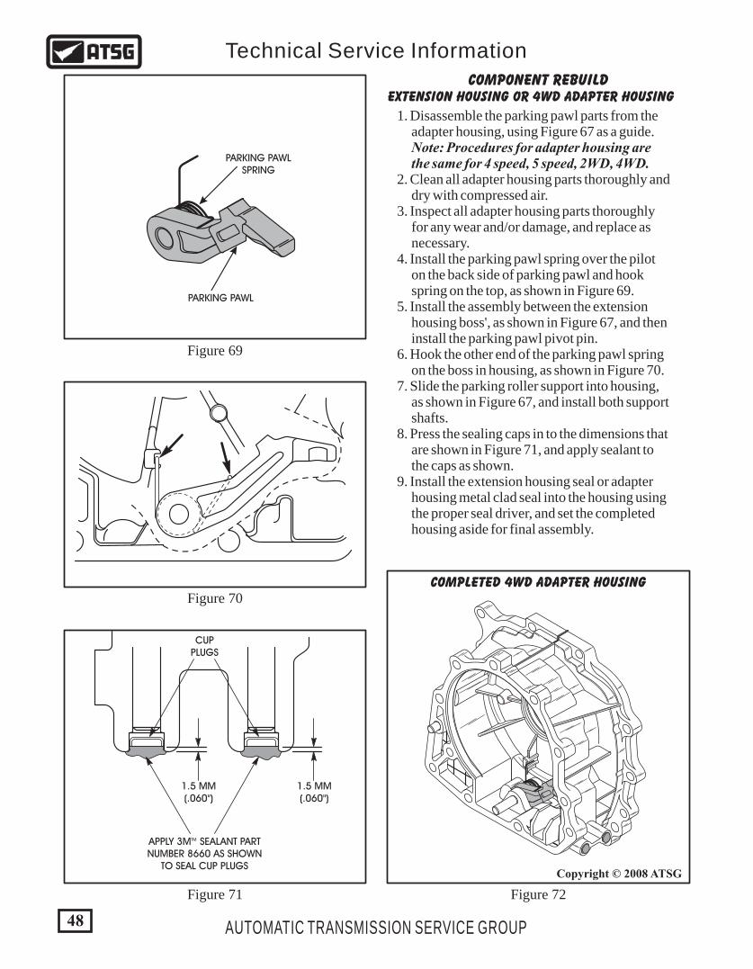
48
Copyright © 2008 ATSG
AUTOMATIC TRANSMISSION SERVICE GROUP
Technical Service Information
1.5 MM(.060")
CUPPLUGS
TMAPPLY 3M SEALANT PARTNUMBER 8660 AS SHOWN
TO SEAL CUP PLUGS
1.5 MM(.060")
PARKING PAWL
PARKING PAWLSPRING
COMPONENT REBUILDEXTENSION HOUSING OR 4WD ADAPTER HOUSING
1. Disassemble the parking pawl parts from the adapter housing, using Figure 67 as a guide. Note: Procedures for adapter housing are the same for 4 speed, 5 speed, 2WD, 4WD. 2. Clean all adapter housing parts thoroughly and dry with compressed air. 3. Inspect all adapter housing parts thoroughly for any wear and/or damage, and replace as necessary. 4. Install the parking pawl spring over the pilot on the back side of parking pawl and hook spring on the top, as shown in Figure 69. 5. Install the assembly between the extension housing boss', as shown in Figure 67, and then install the parking pawl pivot pin. 6. Hook the other end of the parking pawl spring on the boss in housing, as shown in Figure 70. 7. Slide the parking roller support into housing, as shown in Figure 67, and install both support shafts. 8. Press the sealing caps in to the dimensions that are shown in Figure 71, and apply sealant to the caps as shown. 9. Install the extension housing seal or adapter housing metal clad seal into the housing using the proper seal driver, and set the completed housing aside for final assembly.
Figure 69
Figure 70
Figure 71 Figure 72
COMPLETED 4WD ADAPTER HOUSING
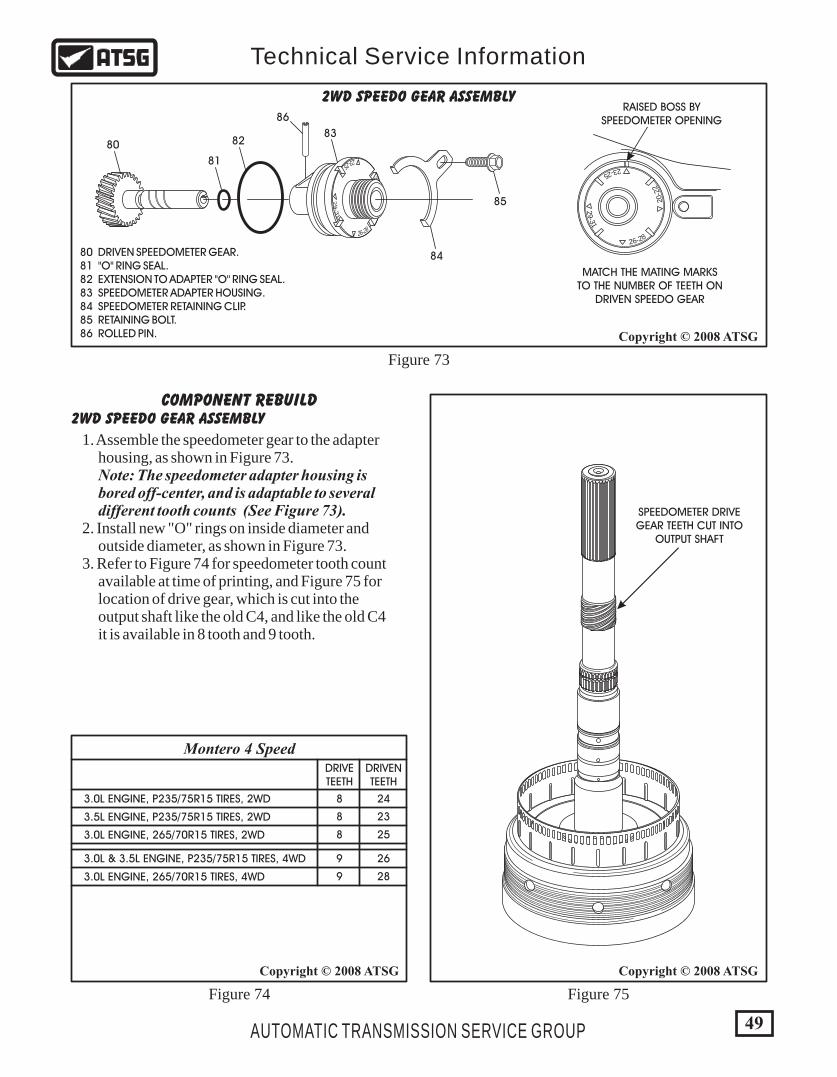
20-2
2
13-
92
82-62
23-25
49
Copyright © 2008 ATSGCopyright © 2008 ATSG
Copyright © 2008 ATSG
AUTOMATIC TRANSMISSION SERVICE GROUP
Technical Service Information
RAISED BOSS BYSPEEDOMETER OPENING
80
81
8283
86
84
85
MATCH THE MATING MARKSTO THE NUMBER OF TEETH ON
DRIVEN SPEEDO GEAR
SPEEDOMETER DRIVEGEAR TEETH CUT INTO
OUTPUT SHAFT
DRIVETEETH
8
8
8
9
9
3.0L ENGINE, P235/75R15 TIRES, 2WD
3.0L ENGINE, 265/70R15 TIRES, 2WD
3.0L ENGINE, 265/70R15 TIRES, 4WD
3.5L ENGINE, P235/75R15 TIRES, 2WD
3.0L & 3.5L ENGINE, P235/75R15 TIRES, 4WD
DRIVENTEETH
24
23
25
28
26
20-2
2
13-9
2
82-62
23-25
COMPONENT REBUILD2WD SPEEDO GEAR ASSEMBLY
2WD SPEEDO GEAR ASSEMBLY
1. Assemble the speedometer gear to the adapter housing, as shown in Figure 73. Note: The speedometer adapter housing is bored off-center, and is adaptable to several different tooth counts (See Figure 73). 2. Install new "O" rings on inside diameter and outside diameter, as shown in Figure 73. 3. Refer to Figure 74 for speedometer tooth count available at time of printing, and Figure 75 for location of drive gear, which is cut into the output shaft like the old C4, and like the old C4 it is available in 8 tooth and 9 tooth.
Figure 73
Figure 74 Figure 75
Montero 4 Speed
80 DRIVEN SPEEDOMETER GEAR. 81 "O" RING SEAL. 82 EXTENSION TO ADAPTER "O" RING SEAL. 83 SPEEDOMETER ADAPTER HOUSING. 84 SPEEDOMETER RETAINING CLIP. 85 RETAINING BOLT. 86 ROLLED PIN.

- 3
R14
918
D 3
1 3
6062
6465
66
67
68
6970
6163
60 OIL PUMP BODY TO CONVERTER HOUSING "O" RING SEAL. 61 CONVERTER HUB SEAL. 62 OIL PUMP BODY. 63 OIL PUMP BODY CONVERTER HUB BUSHING. (NO BUSHING IN EARLY 4 SPEED UNITS) 64 OIL PUMP OUTER GEAR. 65 OIL PUMP INNER GEAR.
66 OIL PUMP COVER TURBINE SHAFT BUSHING. 67 OIL PUMP COVER ASSEMBLY. 68 OIL PUMP COVER TO PUMP BODY BOLTS (7 REQUIRED). 69 OIL PUMP COVER LARGE "HOOK-JOINT" SEAL RINGS (2). 70 OIL PUMP COVER SMALL "HOOK-JOINT" SEAL RINGS (2). 400 NUMBER 1 SELECTIVE THRUST WASHER.
OIL PUMP ASSEMBLY EXPLODED VIEW
400
Figure 76
50
Copyright © 2008 ATSG
AUTOMATIC TRANSMISSION SERVICE GROUP
Technical Service Information

62 OIL PUMP BODY. 64 OIL PUMP OUTER GEAR. 65 OIL PUMP INNER GEAR.
64
MARKSFACING UP
65
62
61 CONVERTER HUB SEAL. 62 OIL PUMP BODY.
61
62
STAKE BUSHING IN PLACE
62 OIL PUMP BODY. 63 OIL PUMP BODY CONVERTER HUB BUSHING.
62
63
51
Copyright © 2008 ATSG
Copyright © 2008 ATSG Copyright © 2008 ATSG
Copyright © 2008 ATSG
AUTOMATIC TRANSMISSION SERVICE GROUP
Technical Service Information
COMPONENT REBUILDOIL PUMP ASSEMBLY
1. Disassemble the oil pump assembly using Figure 76 as a guide. 2. Clean all oil pump parts thoroughly and dry with compressed air. 3. Inspect all oil pump parts thoroughly for any wear and/or damage. 4. Install new oil pump body bushing as needed, as shown in Figure 77, using a proper bushing driver (No bushing in early 4 speed units). 5. Stake the bushing in place using a small punch, as shown in Figure 78. 6. Turn the oil pump body over and install a new converter seal, as shown in Figure 79, using the proper seal driver.
7. Install the outer and inner gears into the pump body, with the marks facing up, as shown in Figure 80. 8. Lubricate the pump gears with a small amount of the proper fluid.
Figure 77
Figure 78
Figure 79
Figure 80
Continued on Page 52

62 PRE-ASSEMBLED OIL PUMP BODY. 67 OIL PUMP COVER ASSEMBLY. 68 OIL PUMP COVER TO PUMP BODY BOLTS (7 REQUIRED).
- 3 R14918
D 3
1 3
68
67
62
Straight Edge
66 OIL PUMP COVER TURBINE SHAFT BUSHING. 67 OIL PUMP COVER ASSEMBLY.
66
67
INNER GEAR TO FACE .0008" - .0015"
.0008" - .002"
.004" - .006"
COMPONENT
Oil Pump Specifications
SPECIFICATION
OUTER GEAR TO FACE
OUTER GEAR TO BODY
52
Copyright © 2008 ATSGCopyright © 2008 ATSG
Copyright © 2008 ATSG
AUTOMATIC TRANSMISSION SERVICE GROUP
Technical Service Information
OIL PUMP ASSEMBLY (CONT'D) 10. Install new stator shaft bushings as necessary, as shown in Figure 82, using the proper driver. 11. Install Sonnax® pump alignment tool through the pump bushing, as shown in Figure 83. Note: Pump alignment tool must be aligned perfectly to fit through the bushing because of the tight tolerances. 12. Install the oil pump cover onto the oil pump body, as shown in Figure 83, and install the 7 retaining bolts. 13. Finger tighten at this time.
Figure 81
Figure 82 Figure 83
Continued on Page 53
SONNAX® PUMPALIGNMENT TOOLNUMBER 41005-TL
9. Measure the oil pump gear clearances using a feeler gauge and a straight edge, as shown in Figure 81. Note: Pump clearance specifications are also shown in Figure 81.
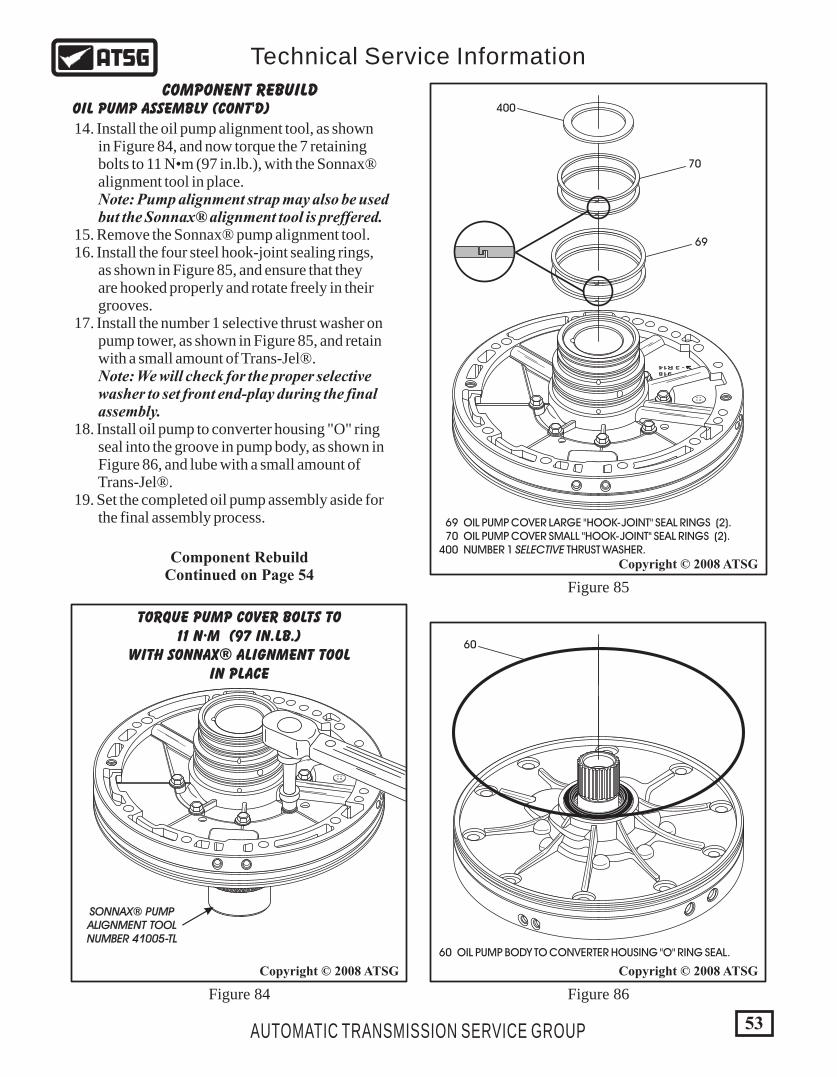
- 3 R14918
D 3
1 3
TORQUE PUMP COVER BOLTS TO11 N·M (97 IN.LB.)
WITH SONNAX® ALIGNMENT TOOLIN PLACE
53
Copyright © 2008 ATSG
Copyright © 2008 ATSG Copyright © 2008 ATSG
AUTOMATIC TRANSMISSION SERVICE GROUP
Technical Service Information
COMPONENT REBUILDOIL PUMP ASSEMBLY (CONT'D)
14. Install the oil pump alignment tool, as shown in Figure 84, and now torque the 7 retaining bolts to 11 N•m (97 in.lb.), with the Sonnax® alignment tool in place. Note: Pump alignment strap may also be used but the Sonnax® alignment tool is preffered. 15. Remove the Sonnax® pump alignment tool. 16. Install the four steel hook-joint sealing rings, as shown in Figure 85, and ensure that they are hooked properly and rotate freely in their grooves. 17. Install the number 1 selective thrust washer on pump tower, as shown in Figure 85, and retain with a small amount of Trans-Jel®. Note: We will check for the proper selective washer to set front end-play during the final assembly. 18. Install oil pump to converter housing "O" ring seal into the groove in pump body, as shown in Figure 86, and lube with a small amount of Trans-Jel®. 19. Set the completed oil pump assembly aside for the final assembly process.
Component RebuildContinued on Page 54
69 OIL PUMP COVER LARGE "HOOK-JOINT" SEAL RINGS (2). 70 OIL PUMP COVER SMALL "HOOK-JOINT" SEAL RINGS (2). 400 NUMBER 1 SELECTIVE THRUST WASHER.
- 3 R14918
D 3
1 3
70
69
400
Figure 84 Figure 86
Figure 85
60 OIL PUMP BODY TO CONVERTER HOUSING "O" RING SEAL.
60
SONNAX® PUMPALIGNMENT TOOLNUMBER 41005-TL
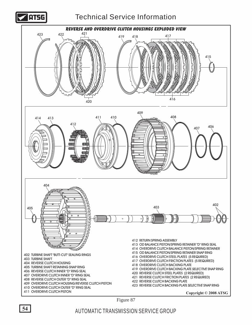
54
Copyright © 2008 ATSG
AUTOMATIC TRANSMISSION SERVICE GROUP
Technical Service Information
R 1
REVERSE AND OVERDRIVE CLUTCH HOUSINGS EXPLODED VIEW
403
404
405
406407
409
416
417418419
408
402
410411
412
413414
415W
420
421422423
402 TURBINE SHAFT "BUTT-CUT" SEALING RINGS 403 TURBINE SHAFT 404 REVERSE CLUTCH HOUSING 405 TURBINE SHAFT RETAINING SNAP RING 406 REVERSE CLUTCH INNER "D" RING SEAL 407 OVERDRIVE CLUTCH INNER "D" RING SEAL 408 REVERSE CLUTCH OUTER "D" RING SEAL 409 OVERDRIVE CLUTCH HOUSING/REVERSE CLUTCH PISTON 410 OVERDRIVE CLUTCH OUTER "D" RING SEAL 411 OVERDRIVE CLUTCH PISTON
412 RETURN SPRING ASSEMBLY 413 OD BALANCE PISTON/SPRING RETAINER "D" RING SEAL 414 OVERDRIVE CLUTCH BALANCE PISTON/SPRING RETAINER 415 OD BALANCE PISTON/SPRING RETAINER SNAP RING 416 OVERDRIVE CLUTCH STEEL PLATES (5 REQUIRED) 417 OVERDRIVE CLUTCH FRICTION PLATES (5 REQUIRED) 418 OVERDRIVE CLUTCH BACKING PLATE 419 OVERDRIVE CLUTCH BACKING PLATE SELECTIVE SNAP RING 420 REVERSE CLUTCH STEEL PLATES (2 REQUIRED) 421 REVERSE CLUTCH FRICTION PLATES (2 REQUIRED) 422 REVERSE CLUTCH BACKING PLATE 423 REVERSE CLUTCH BACKING PLATE SELECTIVE SNAP RING
Figure 87
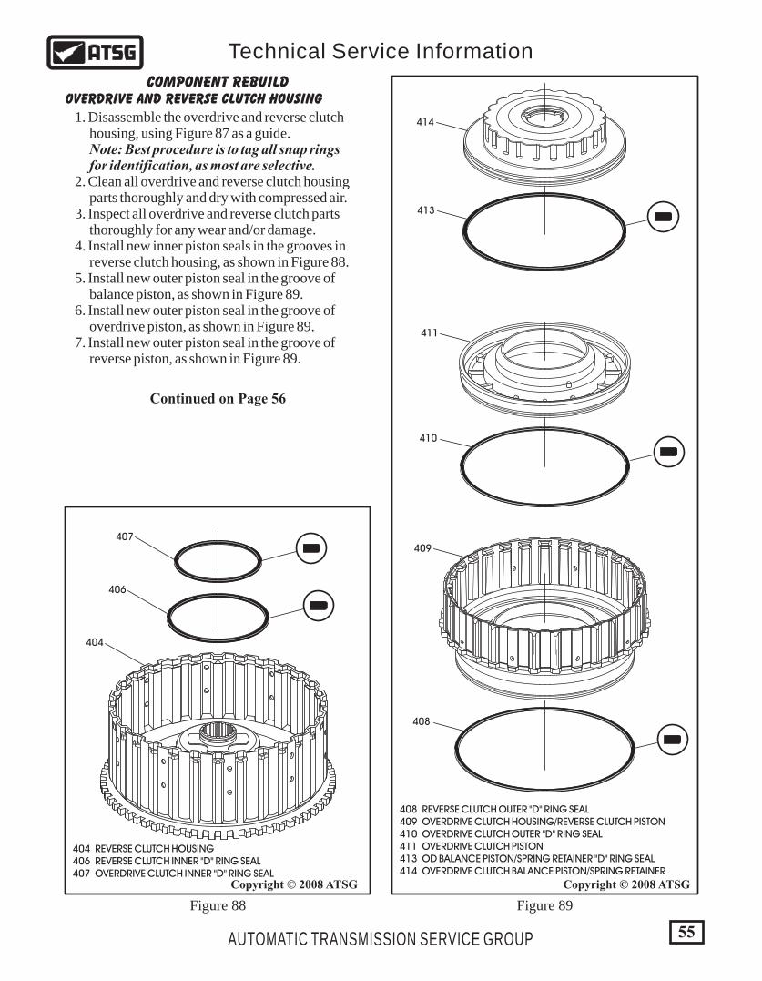
404 REVERSE CLUTCH HOUSING 406 REVERSE CLUTCH INNER "D" RING SEAL 407 OVERDRIVE CLUTCH INNER "D" RING SEAL
408 REVERSE CLUTCH OUTER "D" RING SEAL 409 OVERDRIVE CLUTCH HOUSING/REVERSE CLUTCH PISTON 410 OVERDRIVE CLUTCH OUTER "D" RING SEAL 411 OVERDRIVE CLUTCH PISTON 413 OD BALANCE PISTON/SPRING RETAINER "D" RING SEAL 414 OVERDRIVE CLUTCH BALANCE PISTON/SPRING RETAINER
55
Copyright © 2008 ATSGCopyright © 2008 ATSG
AUTOMATIC TRANSMISSION SERVICE GROUP
Technical Service Information
407
406
414
413
410
411
408
409
404
OVERDRIVE AND REVERSE CLUTCH HOUSINGCOMPONENT REBUILD
1. Disassemble the overdrive and reverse clutch housing, using Figure 87 as a guide. Note: Best procedure is to tag all snap rings for identification, as most are selective. 2. Clean all overdrive and reverse clutch housing parts thoroughly and dry with compressed air. 3. Inspect all overdrive and reverse clutch parts thoroughly for any wear and/or damage. 4. Install new inner piston seals in the grooves in reverse clutch housing, as shown in Figure 88. 5. Install new outer piston seal in the groove of balance piston, as shown in Figure 89. 6. Install new outer piston seal in the groove of overdrive piston, as shown in Figure 89. 7. Install new outer piston seal in the groove of reverse piston, as shown in Figure 89.
Figure 88 Figure 89
Continued on Page 56

404 REVERSE CLUTCH HOUSING 409 OVERDRIVE CLUTCH HOUSING/REVERSE CLUTCH PISTON
404 REVERSE CLUTCH HOUSING 411 OVERDRIVE CLUTCH PISTON 412 RETURN SPRING ASSEMBLY 414 OVERDRIVE CLUTCH BALANCE PISTON/SPRING RETAINER 415 OD BALANCE PISTON/SPRING RETAINER SNAP RING
404
411
PISTON"TAB"
SPRINGHOLE
412
414
415
404HOLE "A"
HOLE "B"
409
56
Copyright © 2008 ATSGCopyright © 2008 ATSG
AUTOMATIC TRANSMISSION SERVICE GROUP
Technical Service Information
Figure 90 Figure 91
OVERDRIVE AND REVERSE CLUTCH HOUSING (CONT'D)COMPONENT REBUILD
8. Lubricate all seals with a small amount of Trans-Jel®, before assembly begins. 9. Install overdrive housing/reverse clutch piston into the reverse clutch housing, as shown in Figure 90. Note: As you install, ensure the lube holes in the two pieces are aligned, as it is shown in Figure 90. 10. Install the overdrive clutch piston into housing, as shown in Figure 91. 11. Install piston return spring assembly, as shown in Figure 91. Note: Ensure that holes in return spring are aligned with tabs on piston (See Figure 91). 12. Install overdrive balance piston, as shown in Figure 91. 13. Compress the assembly and install snap ring, as shown in Figure 91, and ensure snap ring is fully seated.
Continued on Page 57

R 1
404 REVERSE CLUTCH HOUSING 416 OVERDRIVE CLUTCH STEEL PLATES , .098" THICK (5 REQ.) 417 OVERDRIVE CLUTCH FRICTION PLATES (5 REQUIRED) 418 OVERDRIVE CLUTCH BACKING PLATE, .130" THICK 419 OVERDRIVE CLUTCH BACKING PLATE SELECTIVE SNAP RING
404
418
"R1" STAMPFACES UP
419
416
417
OVERDRIVE CLUTCH RETURN SPRINGRETAINER SELECTIVE SNAP RING
THICKNESS
1.48 MM (.058")
1.53 MM (.060")
1.58 MM (.062")
1.63 MM (.064")
I.D. SYMBOL
BROWN
BLACK
NONE
BROWN
PART NUMBER
MR336158
MR336159
MR336160
MR336161
SNAP RING CLEARANCE SHOULD BE0.09MM (.004")
57
Copyright © 2008 ATSGCopyright © 2008 ATSG
AUTOMATIC TRANSMISSION SERVICE GROUP
Technical Service Information
Figure 92 Figure 93
OVERDRIVE AND REVERSE CLUTCH HOUSING (CONT'D)COMPONENT REBUILD
14. While the assembly is compressed, measure with a feeler gauge, the snap ring clearance, as shown in Figure 92. Note: Make a selection as necessary from the chart in Figure 92. 15. Install overdrive clutch plates beginning with a steel plate and alternating with friction plates, as shown in Figure 93. Note: Steel plates must be installed so that no teeth are blocking lube holes, as shown in Figure 97. All plates should be soaked for 30 minutes in the proper fluid before assembly, and the number of plates may vary. 16. Install the overdrive clutch backing plate, as shown in Figure 93, and the "R1" stamp must face up as shown, and must be oriented the same as the steel plates. 17. Install overdrive clutch backing plate selective snap ring, as shown in Figure 93.
Continued on Page 58
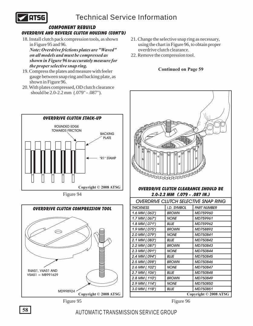
OVERDRIVE AND REVERSE CLUTCH HOUSING (CONT'D)COMPONENT REBUILD
18. Install clutch pack compression tools, as shown in Figure 95 and 96. Note: Overdrive frictions plates are "Waved" on all models and must be compressed as shown in Figure 96 to accurately measure for the proper selective snap ring. 19. Compress the plates and measure with feeler gauge between snap ring and backing plate, as shown in Figure 96. 20. With plates compressed, OD clutch clearance should be 2.0-2.2 mm (.079" - .087").
21. Change the selective snap ring as necessary, using the chart in Figure 96, to obtain proper overdrive clutch clearance. 22. Remove the compression tool.
Continued on Page 59
58
Copyright © 2008 ATSGCopyright © 2008 ATSG
Copyright © 2008 ATSG
AUTOMATIC TRANSMISSION SERVICE GROUP
Technical Service Information
R 1
OVERDRIVE CLUTCH SELECTIVE SNAP RINGTHICKNESS
1.6 MM (.063")
1.7 MM (.067")
1.8 MM (.071")
1.9 MM (.075")
2.0 MM (.079")
2.1 MM (.083")
2.2 MM (.087")
2.3 MM (.091")
2.4 MM (.094")
2.5 MM (.098")
2.6 MM (.102")
2.7 MM (.106")
2.8 MM (.110")
2.9 MM (.114")
3.0 MM (.118")
I.D. SYMBOL
BROWN
NONE
BLUE
BROWN
NONE
BLUE
BROWN
NONE
BLUE
BROWN
NONE
BLUE
BROWN
NONE
BLUE
PART NUMBER
MD759960
MD759961
MD759962
MD758892
MD750841
MD750842
MD750843
MD750844
MD750845
MD750846
MD750847
MD750848
MD750849
MD750850
MD750851
OVERDRIVE CLUTCH CLEARANCE SHOULD BE2.0-2.2 MM (.079 - .087 IN.)
ROUNDED EDGETOWARDS FRICTION
BACKINGPLATE
"R1" STAMP
OVERDRIVE CLUTCH STACK-UP
R4A51, V4A51 ANDV5A51 = MB991629
MD998924
OVERDRIVE CLUTCH COMPRESSION TOOL
Figure 94
Figure 95 Figure 96

59
Copyright © 2008 ATSGCopyright © 2008 ATSG
AUTOMATIC TRANSMISSION SERVICE GROUP
Technical Service Information
404 REVERSE CLUTCH HOUSING 420 REVERSE CLUTCH STEEL PLATES (2 REQUIRED) 421 REVERSE CLUTCH FRICTION PLATES (2 REQUIRED) 422 REVERSE CLUTCH BACKING PLATE 423 REVERSE CLUTCH BACKING PLATE SELECTIVE SNAP RING
R 1
404
422
423
"W" STAMPFACES UP
420421
W
LUBEHOLE
LUBEHOLE
SPACE BETWEENTEETH ON STEEL PLATE
ROUNDED EDGETOWARDS FRICTION
BACKINGPLATE
"W" STAMP
REVERSE CLUTCH STACK-UP
OVERDRIVE AND REVERSE CLUTCH HOUSING (CONT'D)COMPONENT REBUILD
23. Install the reverse clutch plates beginning with a steel plate and alternating with frictions, as shown in Figure 98. Note: Steel plates must be installed so that no teeth are blocking lube holes, as shown in Figure 97. All plates should be soaked for 30 minutes in the proper fluid before assembly, and the number of plates may vary. 24. Install the reverse clutch backing plate, as shown in Figure 98, and the "W" stamp must face up as shown, and must be oriented the same as the steel plates. 25. Install the reverse clutch selective snap ring, as shown in Figure 98.
Continued on Page 60
Figure 97 Figure 98
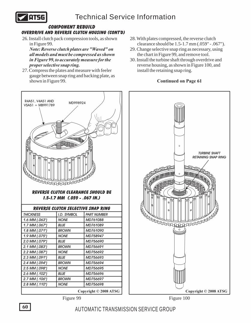
R 1
W
60
Copyright © 2008 ATSGCopyright © 2008 ATSG
AUTOMATIC TRANSMISSION SERVICE GROUP
Technical Service Information
REVERSE CLUTCH SELECTIVE SNAP RINGTHICKNESS
1.6 MM (.063")
1.7 MM (.067")
1.8 MM (.071")
1.9 MM (.075")
2.0 MM (.079")
2.1 MM (.083")
2.2 MM (.087")
2.3 MM (.091")
2.4 MM (.094")
2.5 MM (.098")
2.6 MM (.102")
2.7 MM (.106")
2.8 MM (.110")
I.D. SYMBOL
NONE
BLUE
BROWN
NONE
BLUE
BROWN
NONE
BLUE
BROWN
NONE
BLUE
BROWN
NONE
PART NUMBER
MD761088
MD761089
MD761090
MD758947
MD756690
MD756691
MD756692
MD756693
MD756694
MD756695
MD756696
MD756697
MD756698
REVERSE CLUTCH CLEARANCE SHOULD BE1.5-1.7 MM (.059 - .067 IN.)
R 1
W
TURBINE SHAFTRETAINING SNAP RING
Figure 99 Figure 100
R4A51, V4A51 ANDV5A51 = MB991789
MD998924
OVERDRIVE AND REVERSE CLUTCH HOUSING (CONT'D)COMPONENT REBUILD
26. Install clutch pack compression tools, as shown in Figure 99. Note: Reverse clutch plates are "Waved" on all models and must be compressed as shown in Figure 99, to accurately measure for the proper selective snap ring. 27. Compress the plates and measure with feeler gauge between snap ring and backing plate, as shown in Figure 99. Continued on Page 61
28. With plates compressed, the reverse clutch clearance should be 1.5-1.7 mm (.059" - .067"). 29. Change selective snap ring as necessary, using the chart in Figure 99, and remove tool. 30. Install the turbine shaft through overdrive and reverse housing, as shown in Figure 100, and install the retaining snap ring.
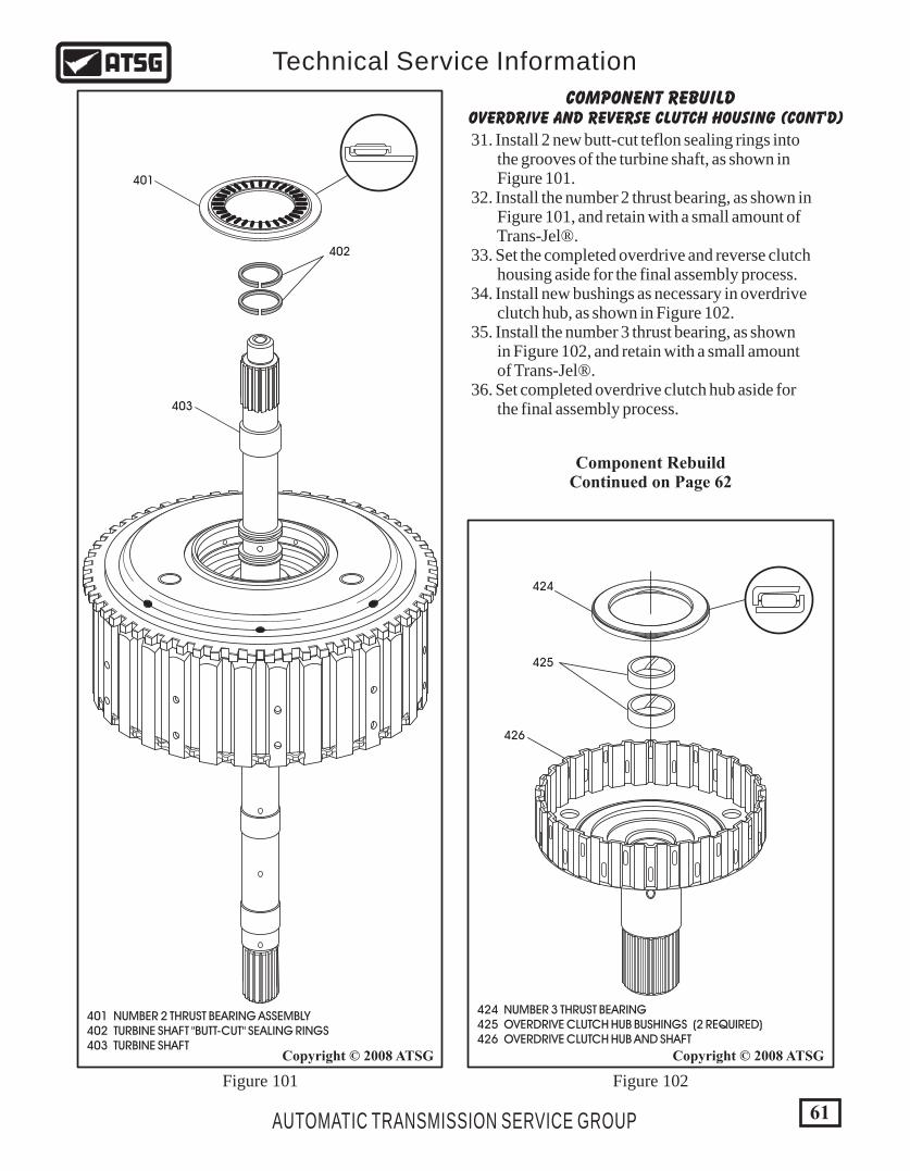
424 NUMBER 3 THRUST BEARING 425 OVERDRIVE CLUTCH HUB BUSHINGS (2 REQUIRED) 426 OVERDRIVE CLUTCH HUB AND SHAFT
424
425
426
401
401 NUMBER 2 THRUST BEARING ASSEMBLY 402 TURBINE SHAFT "BUTT-CUT" SEALING RINGS 403 TURBINE SHAFT
402
403
61
Copyright © 2008 ATSGCopyright © 2008 ATSG
AUTOMATIC TRANSMISSION SERVICE GROUP
Technical Service Information
OVERDRIVE AND REVERSE CLUTCH HOUSING (CONT'D)COMPONENT REBUILD
31. Install 2 new butt-cut teflon sealing rings into the grooves of the turbine shaft, as shown in Figure 101. 32. Install the number 2 thrust bearing, as shown in Figure 101, and retain with a small amount of Trans-Jel®. 33. Set the completed overdrive and reverse clutch housing aside for the final assembly process. 34. Install new bushings as necessary in overdrive clutch hub, as shown in Figure 102. 35. Install the number 3 thrust bearing, as shown in Figure 102, and retain with a small amount of Trans-Jel®. 36. Set completed overdrive clutch hub aside for the final assembly process.
Figure 101 Figure 102
Component RebuildContinued on Page 62
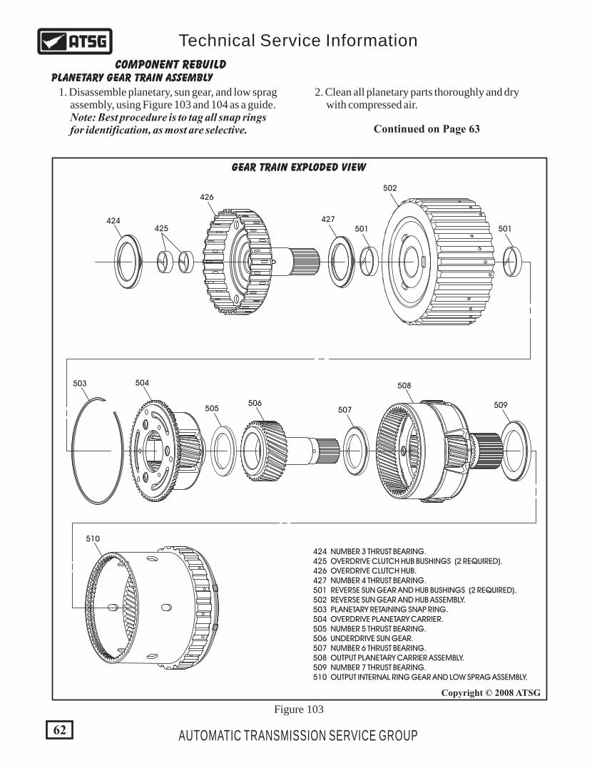
GEAR TRAIN EXPLODED VIEW
503 504
505506
507
508
509
510
424 NUMBER 3 THRUST BEARING. 425 OVERDRIVE CLUTCH HUB BUSHINGS (2 REQUIRED). 426 OVERDRIVE CLUTCH HUB. 427 NUMBER 4 THRUST BEARING. 501 REVERSE SUN GEAR AND HUB BUSHINGS (2 REQUIRED). 502 REVERSE SUN GEAR AND HUB ASSEMBLY. 503 PLANETARY RETAINING SNAP RING. 504 OVERDRIVE PLANETARY CARRIER. 505 NUMBER 5 THRUST BEARING. 506 UNDERDRIVE SUN GEAR. 507 NUMBER 6 THRUST BEARING. 508 OUTPUT PLANETARY CARRIER ASSEMBLY. 509 NUMBER 7 THRUST BEARING. 510 OUTPUT INTERNAL RING GEAR AND LOW SPRAG ASSEMBLY.
Figure 103
424425
426
427501 501
502
62
Copyright © 2008 ATSG
AUTOMATIC TRANSMISSION SERVICE GROUP
Technical Service Information
PLANETARY GEAR TRAIN ASSEMBLYCOMPONENT REBUILD
1. Disassemble planetary, sun gear, and low sprag assembly, using Figure 103 and 104 as a guide. Note: Best procedure is to tag all snap rings for identification, as most are selective.
2. Clean all planetary parts thoroughly and dry with compressed air.
Continued on Page 63
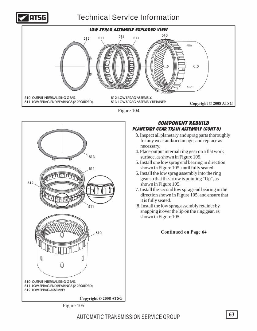
510 OUTPUT INTERNAL RING GEAR. 511 LOW SPRAG END BEARINGS (2 REQUIRED).
512 LOW SPRAG ASSEMBLY. 513 LOW SPRAG ASSEMBLY RETAINER.
LOW SPRAG ASSEMBLY EXPLODED VIEW
510
511
512
511
513
510 OUTPUT INTERNAL RING GEAR. 511 LOW SPRAG END BEARINGS (2 REQUIRED). 512 LOW SPRAG ASSEMBLY.
COMPONENT REBUILDPLANETARY GEAR TRAIN ASSEMBLY (CONT'D)
3. Inspect all planetary and sprag parts thoroughly for any wear and/or damage, and replace as necessary. 4. Place output internal ring gear on a flat work surface, as shown in Figure 105. 5. Install one low sprag end bearing in direction shown in Figure 105, until fully seated. 6. Install the low sprag assembly into the ring gear so that the arrow is pointing "Up", as shown in Figure 105. 7. Install the second low sprag end bearing in the direction shown in Figure 105, and ensure that it is fully seated. 8. Install the low sprag assembly retainer by snapping it over the lip on the ring gear, as shown in Figure 105.
Figure 104
Figure 105
Continued on Page 64
510511511 512
513
63
Copyright © 2008 ATSG
Copyright © 2008 ATSG
AUTOMATIC TRANSMISSION SERVICE GROUP
Technical Service Information
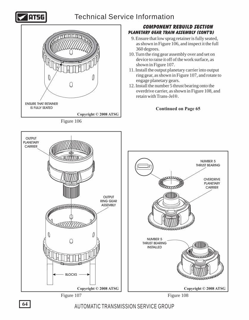
COMPONENT REBUILD SECTIONPLANETARY GEAR TRAIN ASSEMBLY (CONT'D)
9. Ensure that low sprag retainer is fully seated, as shown in Figure 106, and inspect it the full 360 degrees. 10. Turn the ring gear assembly over and set on device to raise it off of the work surface, as shown in Figure 107. 11. Install the output planetary carrier into output ring gear, as shown in Figure 107, and rotate to engage planetary gears. 12. Install the number 5 thrust bearing onto the overdrive carrier, as shown in Figure 108, and retain with Trans-Jel®.
Continued on Page 65
Figure 106
Figure 107 Figure 108
ENSURE THAT RETAINERIS FULLY SEATED
OUTPUTPLANETARYCARRIER
OUTPUTRING GEARASSEMBLY
NUMBER 5THRUST BEARING
NUMBER 5THRUST BEARING
INSTALLED
OVERDRIVEPLANETARYCARRIER
BLOCKS
64
Copyright © 2008 ATSGCopyright © 2008 ATSG
Copyright © 2008 ATSG
AUTOMATIC TRANSMISSION SERVICE GROUP
Technical Service Information
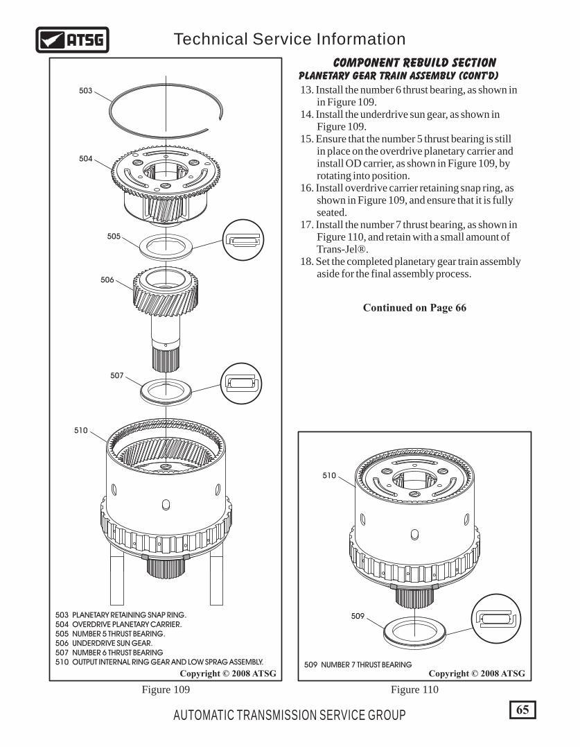
COMPONENT REBUILD SECTIONPLANETARY GEAR TRAIN ASSEMBLY (CONT'D)
13. Install the number 6 thrust bearing, as shown in in Figure 109. 14. Install the underdrive sun gear, as shown in Figure 109. 15. Ensure that the number 5 thrust bearing is still in place on the overdrive planetary carrier and install OD carrier, as shown in Figure 109, by rotating into position. 16. Install overdrive carrier retaining snap ring, as shown in Figure 109, and ensure that it is fully seated. 17. Install the number 7 thrust bearing, as shown in Figure 110, and retain with a small amount of Trans-Jel®. 18. Set the completed planetary gear train assembly aside for the final assembly process.
Continued on Page 66
503
504
505
506
507
509
510
510
503 PLANETARY RETAINING SNAP RING. 504 OVERDRIVE PLANETARY CARRIER. 505 NUMBER 5 THRUST BEARING. 506 UNDERDRIVE SUN GEAR. 507 NUMBER 6 THRUST BEARING 510 OUTPUT INTERNAL RING GEAR AND LOW SPRAG ASSEMBLY. 509 NUMBER 7 THRUST BEARING
65
Copyright © 2008 ATSGCopyright © 2008 ATSG
AUTOMATIC TRANSMISSION SERVICE GROUP
Technical Service Information
Figure 109 Figure 110
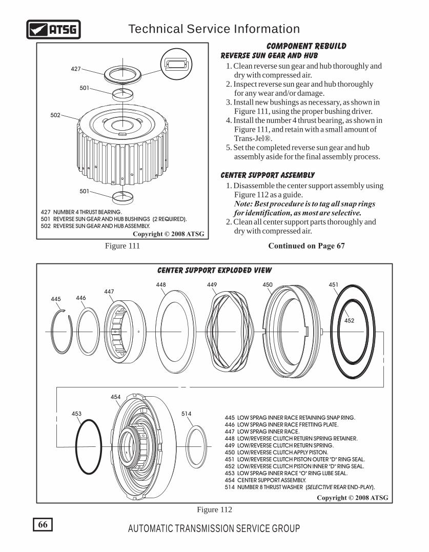
427 NUMBER 4 THRUST BEARING. 501 REVERSE SUN GEAR AND HUB BUSHINGS (2 REQUIRED). 502 REVERSE SUN GEAR AND HUB ASSEMBLY.
427
501
501
502
66
Copyright © 2008 ATSG
Copyright © 2008 ATSG
AUTOMATIC TRANSMISSION SERVICE GROUP
Technical Service Information
514
445 446447
448 449 450
453
454
451
452
445 LOW SPRAG INNER RACE RETAINING SNAP RING. 446 LOW SPRAG INNER RACE FRETTING PLATE. 447 LOW SPRAG INNER RACE. 448 LOW/REVERSE CLUTCH RETURN SPRING RETAINER. 449 LOW/REVERSE CLUTCH RETURN SPRING. 450 LOW/REVERSE CLUTCH APPLY PISTON. 451 LOW/REVERSE CLUTCH PISTON OUTER "D" RING SEAL. 452 LOW/REVERSE CLUTCH PISTON INNER "D" RING SEAL. 453 LOW SPRAG INNER RACE "O" RING LUBE SEAL. 454 CENTER SUPPORT ASSEMBLY. 514 NUMBER 8 THRUST WASHER (SELECTIVE REAR END-PLAY).
CENTER SUPPORT EXPLODED VIEW
Figure 111
Figure 112
COMPONENT REBUILDREVERSE SUN GEAR AND HUB
CENTER SUPPORT ASSEMBLY
1. Clean reverse sun gear and hub thoroughly and dry with compressed air. 2. Inspect reverse sun gear and hub thoroughly for any wear and/or damage. 3. Install new bushings as necessary, as shown in Figure 111, using the proper bushing driver. 4. Install the number 4 thrust bearing, as shown in Figure 111, and retain with a small amount of Trans-Jel®. 5. Set the completed reverse sun gear and hub assembly aside for the final assembly process.
1. Disassemble the center support assembly using Figure 112 as a guide. Note: Best procedure is to tag all snap rings for identification, as most are selective. 2. Clean all center support parts thoroughly and dry with compressed air.
Continued on Page 67
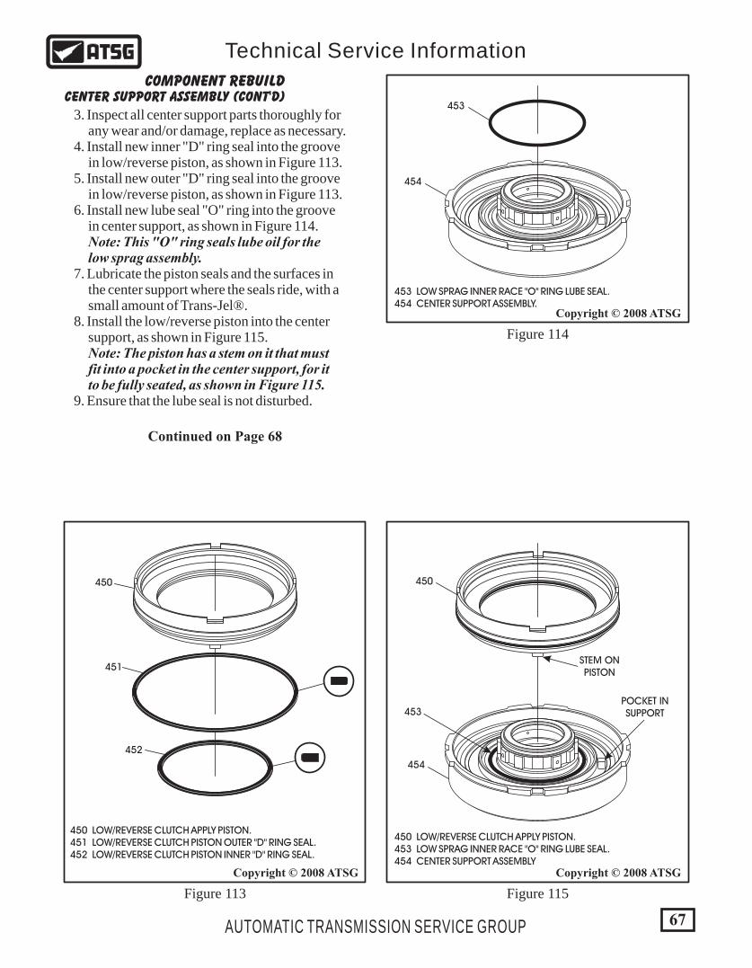
67
Copyright © 2008 ATSG
Copyright © 2008 ATSG
Copyright © 2008 ATSG
AUTOMATIC TRANSMISSION SERVICE GROUP
Technical Service Information
450
451
452
450 LOW/REVERSE CLUTCH APPLY PISTON. 451 LOW/REVERSE CLUTCH PISTON OUTER "D" RING SEAL. 452 LOW/REVERSE CLUTCH PISTON INNER "D" RING SEAL.
450 LOW/REVERSE CLUTCH APPLY PISTON. 453 LOW SPRAG INNER RACE "O" RING LUBE SEAL. 454 CENTER SUPPORT ASSEMBLY
450
454
453
STEM ONPISTON
POCKET INSUPPORT
453 LOW SPRAG INNER RACE "O" RING LUBE SEAL. 454 CENTER SUPPORT ASSEMBLY.
454
453
Figure 113 Figure 115
Figure 114
COMPONENT REBUILDCENTER SUPPORT ASSEMBLY (CONT'D)
3. Inspect all center support parts thoroughly for any wear and/or damage, replace as necessary. 4. Install new inner "D" ring seal into the groove in low/reverse piston, as shown in Figure 113. 5. Install new outer "D" ring seal into the groove in low/reverse piston, as shown in Figure 113. 6. Install new lube seal "O" ring into the groove in center support, as shown in Figure 114. Note: This "O" ring seals lube oil for the low sprag assembly. 7. Lubricate the piston seals and the surfaces in the center support where the seals ride, with a small amount of Trans-Jel®. 8. Install the low/reverse piston into the center support, as shown in Figure 115. Note: The piston has a stem on it that must fit into a pocket in the center support, for it to be fully seated, as shown in Figure 115. 9. Ensure that the lube seal is not disturbed.
Continued on Page 68
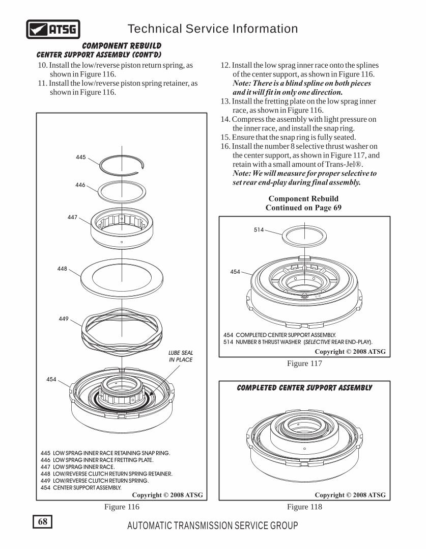
Copyright © 2008 ATSGCopyright © 2008 ATSG
Copyright © 2008 ATSG
445 LOW SPRAG INNER RACE RETAINING SNAP RING. 446 LOW SPRAG INNER RACE FRETTING PLATE. 447 LOW SPRAG INNER RACE. 448 LOW/REVERSE CLUTCH RETURN SPRING RETAINER. 449 LOW/REVERSE CLUTCH RETURN SPRING. 454 CENTER SUPPORT ASSEMBLY.
454
LUBE SEALIN PLACE
445
446
447
448
449
68 AUTOMATIC TRANSMISSION SERVICE GROUP
Technical Service Information
COMPLETED CENTER SUPPORT ASSEMBLY
# 2 # 2
514
454
454 COMPLETED CENTER SUPPORT ASSEMBLY. 514 NUMBER 8 THRUST WASHER (SELECTIVE REAR END-PLAY).
Figure 116 Figure 118
Figure 117
Component RebuildContinued on Page 69
COMPONENT REBUILDCENTER SUPPORT ASSEMBLY (CONT'D)
10. Install the low/reverse piston return spring, as shown in Figure 116. 11. Install the low/reverse piston spring retainer, as shown in Figure 116.
12. Install the low sprag inner race onto the splines of the center support, as shown in Figure 116. Note: There is a blind spline on both pieces and it will fit in only one direction. 13. Install the fretting plate on the low sprag inner race, as shown in Figure 116. 14. Compress the assembly with light pressure on the inner race, and install the snap ring. 15. Ensure that the snap ring is fully seated. 16. Install the number 8 selective thrust washer on the center support, as shown in Figure 117, and retain with a small amount of Trans-Jel®. Note: We will measure for proper selective to set rear end-play during final assembly.
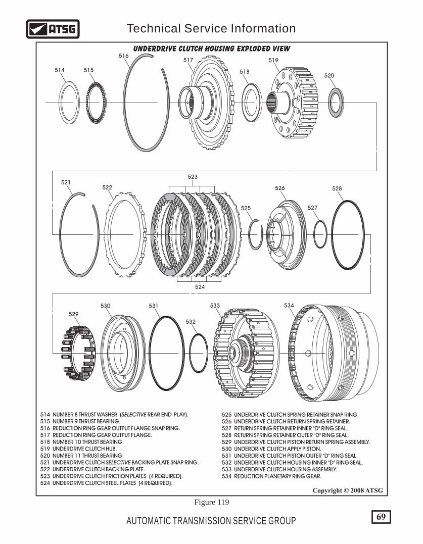
69
Copyright © 2008 ATSG
AUTOMATIC TRANSMISSION SERVICE GROUP
Technical Service Information
UNDERDRIVE CLUTCH HOUSING EXPLODED VIEW
520
517 519
518515514
525 527
526 528
530 531 533 534
529
532
524
523521
516
522
Figure 119
514 NUMBER 8 THRUST WASHER (SELECTIVE REAR END-PLAY). 515 NUMBER 9 THRUST BEARING. 516 REDUCTION RING GEAR OUTPUT FLANGE SNAP RING. 517 REDUCTION RING GEAR OUTPUT FLANGE. 518 NUMBER 10 THRUST BEARING. 519 UNDERDRIVE CLUTCH HUB. 520 NUMBER 11 THRUST BEARING. 521 UNDERDRIVE CLUTCH SELECTIVE BACKING PLATE SNAP RING. 522 UNDERDRIVE CLUTCH BACKING PLATE. 523 UNDERDRIVE CLUTCH FRICTION PLATES (4 REQUIRED). 524 UNDERDRIVE CLUTCH STEEL PLATES (4 REQUIRED).
525 UNDERDRIVE CLUTCH SPRING RETAINER SNAP RING. 526 UNDERDRIVE CLUTCH RETURN SPRING RETAINER. 527 RETURN SPRING RETAINER INNER "D" RING SEAL. 528 RETURN SPRING RETAINER OUTER "D" RING SEAL. 529 UNDERDRIVE CLUTCH PISTON RETURN SPRING ASSEMBLY. 530 UNDERDRIVE CLUTCH APPLY PISTON. 531 UNDERDRIVE CLUTCH PISTON OUTER "D" RING SEAL. 532 UNDERDRIVE CLUTCH HOUSING INNER "D" RING SEAL. 533 UNDERDRIVE CLUTCH HOUSING ASSEMBLY. 534 REDUCTION PLANETARY RING GEAR.

527
SNAP RING GROOVE"D" RING SEAL GROOVEEXHAUST GROOVE
533
532
527 RETURN SPRING RETAINER INNER "D" RING SEAL. 532 UNDERDRIVE CLUTCH HOUSING INNER "D" RING SEAL. 533 UNDERDRIVE CLUTCH HOUSING ASSEMBLY.
530
531
526
528
526 UNDERDRIVE CLUTCH RETURN SPRING RETAINER. 528 RETURN SPRING RETAINER OUTER "D" RING SEAL. 530 UNDERDRIVE CLUTCH APPLY PISTON.
70
Copyright © 2008 ATSGCopyright © 2008 ATSG
Copyright © 2008 ATSG
AUTOMATIC TRANSMISSION SERVICE GROUP
Technical Service Information
COMPONENT REBUILDREDUCTION ANNULUS, UNDERDRIVE CLUTCH
1. Disassemble reduction annulus and underdrive clutch housing using Figure 119 as a guide. Note: Best procedure is to tag all snap rings fpr identification, as most are selective. 2. Clean all reduction annulus and underdrive clutch housing parts thoroughly and dry with compressed air.
3. Inspect all reduction annulus and underdrive clutch housing parts thoroughly for any wear and/or damage, replace as necessary. 4. Install underdrive clutch piston inner "D" ring seal, as shown in Figure 120. 5. Install underdrive clutch return spring retainer inner "D" ring seal, as shown in Figure 120. Note: This seal can be installed in the wrong groove "very" easily. There is a snap ring groove, seal groove, and an exhaust groove. The "D" ring seal goes in the 2nd groove, as shown in Figure 121. 6. Install the outer "D" ring seal into groove of the underdrive clutch piston, as shown in Figure 122. 7. Install the outer "D" ring seal into groove of the underdrive clutch spring retainer, as shown in Figure 122.
Figure 120
Figure 121 Figure 122
Continued on Page 71
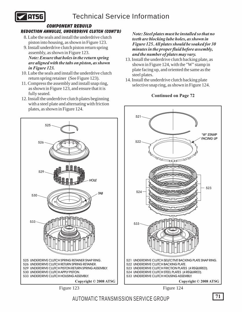
525
533533
529
524523
521
522
"W" STAMPFACING UP
W526
HOLE
TAB530
525 UNDERDRIVE CLUTCH SPRING RETAINER SNAP RING. 526 UNDERDRIVE CLUTCH RETURN SPRING RETAINER. 529 UNDERDRIVE CLUTCH PISTON RETURN SPRING ASSEMBLY. 530 UNDERDRIVE CLUTCH APPLY PISTON. 533 UNDERDRIVE CLUTCH HOUSING ASSEMBLY.
521 UNDERDRIVE CLUTCH SELECTIVE BACKING PLATE SNAP RING.522 UNDERDRIVE CLUTCH BACKING PLATE.523 UNDERDRIVE CLUTCH FRICTION PLATES (4 REQUIRED).524 UNDERDRIVE CLUTCH STEEL PLATES (4 REQUIRED).533 UNDERDRIVE CLUTCH HOUSING ASSEMBLY.
71
Copyright © 2008 ATSGCopyright © 2008 ATSG
AUTOMATIC TRANSMISSION SERVICE GROUP
Technical Service Information
COMPONENT REBUILDREDUCTION ANNULUS, UNDERDRIVE CLUTCH (CONT'D)
8. Lube the seals and install the underdrive clutch piston into housing, as shown in Figure 123. 9. Install underdrive clutch piston return spring assembly, as shown in Figure 123. Note: Ensure that holes in the return spring are aligned with the tabs on piston, as shown in Figure 123. 10. Lube the seals and install the underdrive clutch return spring retainer (See Figure 123). 11. Compress the assembly and install snap ring, as shown in Figure 123, and ensure that it is fully seated. 12. Install the underdrive clutch plates beginning with a steel plate and alternating with friction plates, as shown in Figure 124.
Note: Steel plates must be installed so that no teeth are blocking lube holes, as shown in Figure 125. All plates should be soaked for 30 minutes in the proper fluid before assembly, and the number of plates may vary. 13. Install the underdrive clutch backing plate, as shown in Figure 124, with the "W" stamp in plate facing up, and oriented the same as the steel plates. 14. Install the underdrive clutch backing plate selective snap ring, as shown in Figure 124.
Continued on Page 72
Figure 123 Figure 124

UNDERDRIVE CLUTCH SELECTIVE SNAP RINGTHICKNESS
1.6 MM (.063")
1.7 MM (.067")
1.8 MM (.071")
1.9 MM (.075")
2.0 MM (.079")
2.1 MM (.083")
2.2 MM (.087")
2.3 MM (.091")
2.4 MM (.094")
2.5 MM (.098")
2.6 MM (.102")
2.7 MM (.106")
2.8 MM (.110")
2.9 MM (.114")
3.0 MM (.118")
I.D. SYMBOL
BROWN
NONE
BLUE
BROWN
NONE
BLUE
BROWN
NONE
BLUE
BROWN
NONE
BLUE
BROWN
NONE
BLUE
PART NUMBER
MD759960
MD759961
MD759962
MD758892
MD750841
MD750842
MD750843
MD750844
MD750845
MD750846
MD750847
MD750848
MD750849
MD750850
MD750851
UNDERDRIVE CLUTCH CLEARANCE SHOULD BE1.6-1.8 MM (.063 - .071 IN.)
72
Copyright © 2008 ATSGCopyright © 2008 ATSG
AUTOMATIC TRANSMISSION SERVICE GROUP
Technical Service Information
COMPONENT REBUILDREDUCTION ANNULUS, UNDERDRIVE CLUTCH (CONT'D)
15. Install clutch pack compression tools, as shown in Figure 126. Note: Underdrive clutch plates are "Waved" on all models and must be compressed, as shown in Figure 126, to accurately measure for the proper selective snap ring. 16. Compress the plates and measure with feeler gauge between snap ring and backing plate, as shown in Figure 126. 17. With plates compressed UD clutch clearance should be 1.6-1.8 mm (.063"-.071"). 18. Change the selective snap ring as necessary, using the chart in Figure 126, to obtain proper underdrive clutch clearance. 19. Remove the compression tools.
LUBEHOLE
LUBEHOLE
MB991629
MD998924
SPACE BETWEENTEETH ON STEEL PLATE
ROUNDED EDGETOWARDS FRICTION
BACKINGPLATE
"W" STAMP
UNDERDRIVE CLUTCH STACK-UP
Figure 125 Figure 126
Continued on Page 73
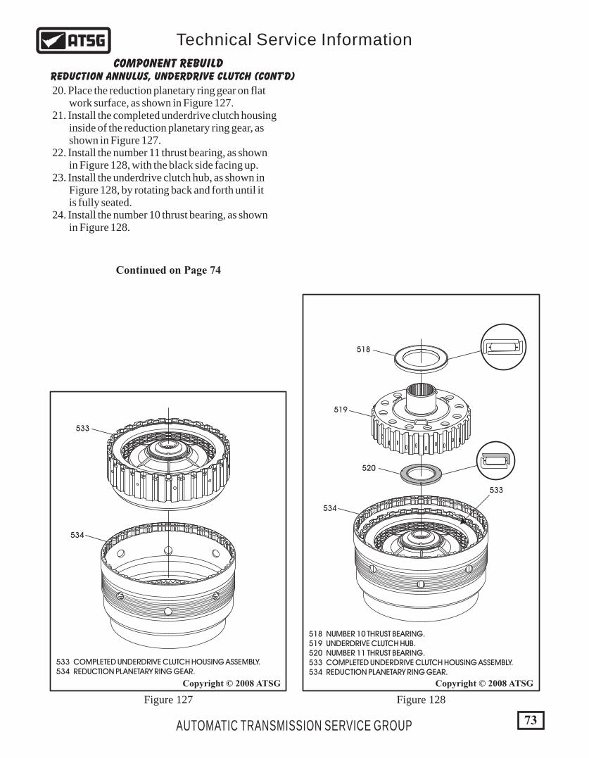
534
534
533
533
533 COMPLETED UNDERDRIVE CLUTCH HOUSING ASSEMBLY. 534 REDUCTION PLANETARY RING GEAR.
518 NUMBER 10 THRUST BEARING. 519 UNDERDRIVE CLUTCH HUB. 520 NUMBER 11 THRUST BEARING. 533 COMPLETED UNDERDRIVE CLUTCH HOUSING ASSEMBLY. 534 REDUCTION PLANETARY RING GEAR.
519
520
518
73
Copyright © 2008 ATSGCopyright © 2008 ATSG
AUTOMATIC TRANSMISSION SERVICE GROUP
Technical Service Information
COMPONENT REBUILDREDUCTION ANNULUS, UNDERDRIVE CLUTCH (CONT'D)
20. Place the reduction planetary ring gear on flat work surface, as shown in Figure 127. 21. Install the completed underdrive clutch housing inside of the reduction planetary ring gear, as shown in Figure 127. 22. Install the number 11 thrust bearing, as shown in Figure 128, with the black side facing up. 23. Install the underdrive clutch hub, as shown in Figure 128, by rotating back and forth until it is fully seated. 24. Install the number 10 thrust bearing, as shown in Figure 128.
Continued on Page 74
Figure 127 Figure 128
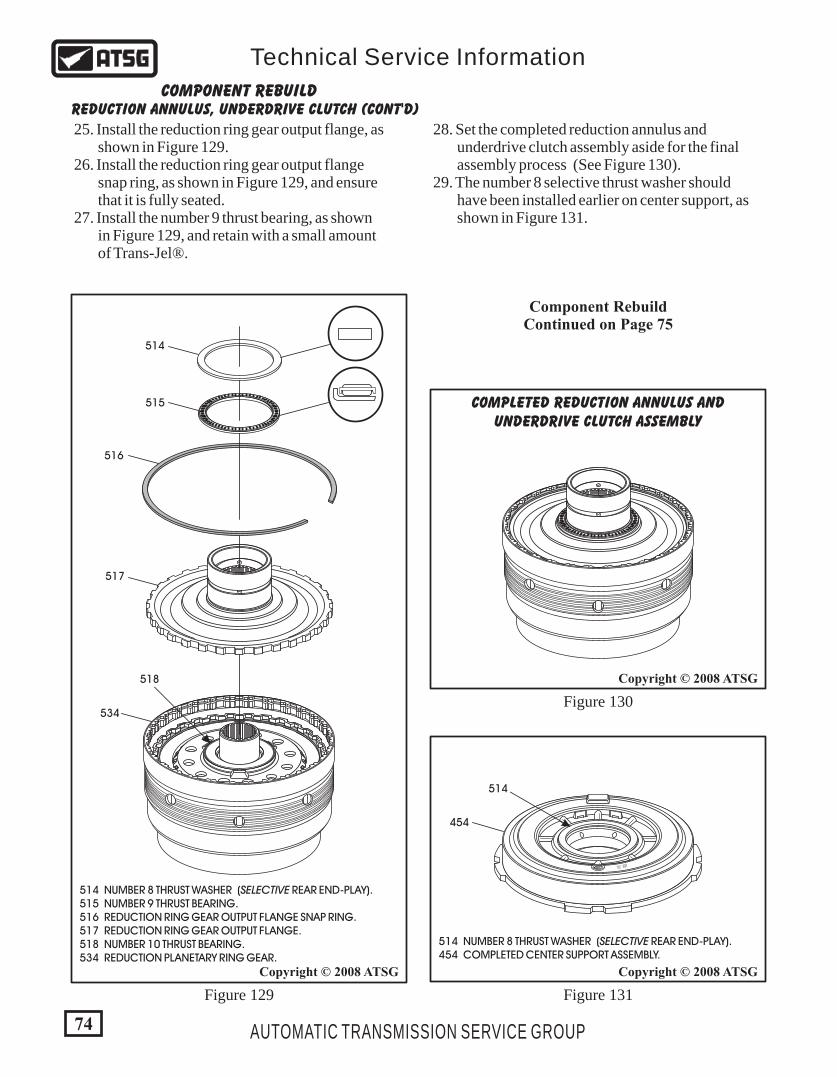
534
514 NUMBER 8 THRUST WASHER (SELECTIVE REAR END-PLAY). 515 NUMBER 9 THRUST BEARING. 516 REDUCTION RING GEAR OUTPUT FLANGE SNAP RING. 517 REDUCTION RING GEAR OUTPUT FLANGE. 518 NUMBER 10 THRUST BEARING. 534 REDUCTION PLANETARY RING GEAR.
514 NUMBER 8 THRUST WASHER (SELECTIVE REAR END-PLAY). 454 COMPLETED CENTER SUPPORT ASSEMBLY.
518
514
515
516
517
514
# 2 # 2
454
COMPLETED REDUCTION ANNULUS ANDUNDERDRIVE CLUTCH ASSEMBLY
COMPONENT REBUILDREDUCTION ANNULUS, UNDERDRIVE CLUTCH (CONT'D)
25. Install the reduction ring gear output flange, as shown in Figure 129. 26. Install the reduction ring gear output flange snap ring, as shown in Figure 129, and ensure that it is fully seated. 27. Install the number 9 thrust bearing, as shown in Figure 129, and retain with a small amount of Trans-Jel®.
28. Set the completed reduction annulus and underdrive clutch assembly aside for the final assembly process (See Figure 130). 29. The number 8 selective thrust washer should have been installed earlier on center support, as shown in Figure 131.
Component RebuildContinued on Page 75
Figure 129 Figure 131
Figure 130
74
Copyright © 2008 ATSGCopyright © 2008 ATSG
Copyright © 2008 ATSG
AUTOMATIC TRANSMISSION SERVICE GROUP
Technical Service Information
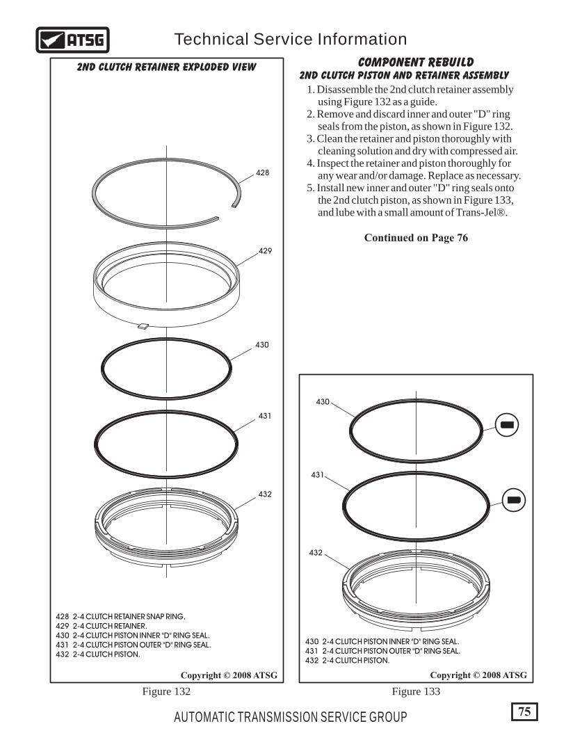
75AUTOMATIC TRANSMISSION SERVICE GROUP
Technical Service Information
Copyright © 2008 ATSG
COMPONENT REBUILD2ND CLUTCH PISTON AND RETAINER ASSEMBLY
1. Disassemble the 2nd clutch retainer assembly using Figure 132 as a guide. 2. Remove and discard inner and outer "D" ring seals from the piston, as shown in Figure 132. 3. Clean the retainer and piston thoroughly with cleaning solution and dry with compressed air. 4. Inspect the retainer and piston thoroughly for any wear and/or damage. Replace as necessary. 5. Install new inner and outer "D" ring seals onto the 2nd clutch piston, as shown in Figure 133, and lube with a small amount of Trans-Jel®.
429
430
430
431
431
432
432
Figure 132 Figure 133
2ND CLUTCH RETAINER EXPLODED VIEW
Continued on Page 76
428
428 2-4 CLUTCH RETAINER SNAP RING. 429 2-4 CLUTCH RETAINER. 430 2-4 CLUTCH PISTON INNER "D" RING SEAL. 431 2-4 CLUTCH PISTON OUTER "D" RING SEAL. 432 2-4 CLUTCH PISTON.
Copyright © 2008 ATSG
430 2-4 CLUTCH PISTON INNER "D" RING SEAL. 431 2-4 CLUTCH PISTON OUTER "D" RING SEAL. 432 2-4 CLUTCH PISTON.
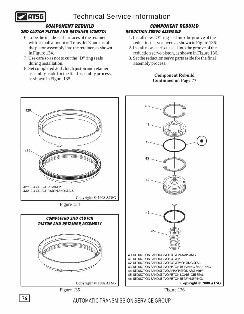
40 REDUCTION BAND SERVO COVER SNAP RING. 41 REDUCTION BAND SERVO COVER. 42 REDUCTION BAND SERVO COVER "O" RING SEAL. 43 REDUCTION BAND SERVO PISTON RETAINING SNAP RING. 44 REDUCTION BAND SERVO APPLY PISTON ASSEMBLY. 45 REDUCTION BAND SERVO PISTON SCARF-CUT SEAL. 46 REDUCTION BAND SERVO PISTON RETURN SPRING.
76 AUTOMATIC TRANSMISSION SERVICE GROUP
Technical Service Information
Copyright © 2008 ATSG
432
429
COMPONENT REBUILD COMPONENT REBUILD2ND CLUTCH PISTON AND RETAINER (CONT'D) REDUCTION SERVO ASSEMBLY
6. Lube the inside seal surfaces of the retainer with a small amount of Trans-Jel® and install the piston assembly into the retainer, as shown in Figure 134. 7. Use care so as not to cut the "D" ring seals during installation. 8. Set completed 2nd clutch piston and retainer assembly aside for the final assembly process, as shown in Figure 135.
Component RebuildContinued on Page 77
Figure 134
Figure 135 Figure 136
Copyright © 2008 ATSG Copyright © 2008 ATSG
COMPLETED 2ND CLUTCHPISTON AND RETAINER ASSEMBLY
1010
40
41
42
429 2-4 CLUTCH RETAINER. 432 2-4 CLUTCH PISTON AND SEALS.
43
44
45
46
1. Install new "O" ring seal into the groove of the reduction servo cover, as shown in Figure 136. 2. Install new scarf-cut seal into the groove of the reduction servo piston, as shown in Figure 136. 3. Set the reduction servo parts aside for the final assembly process.
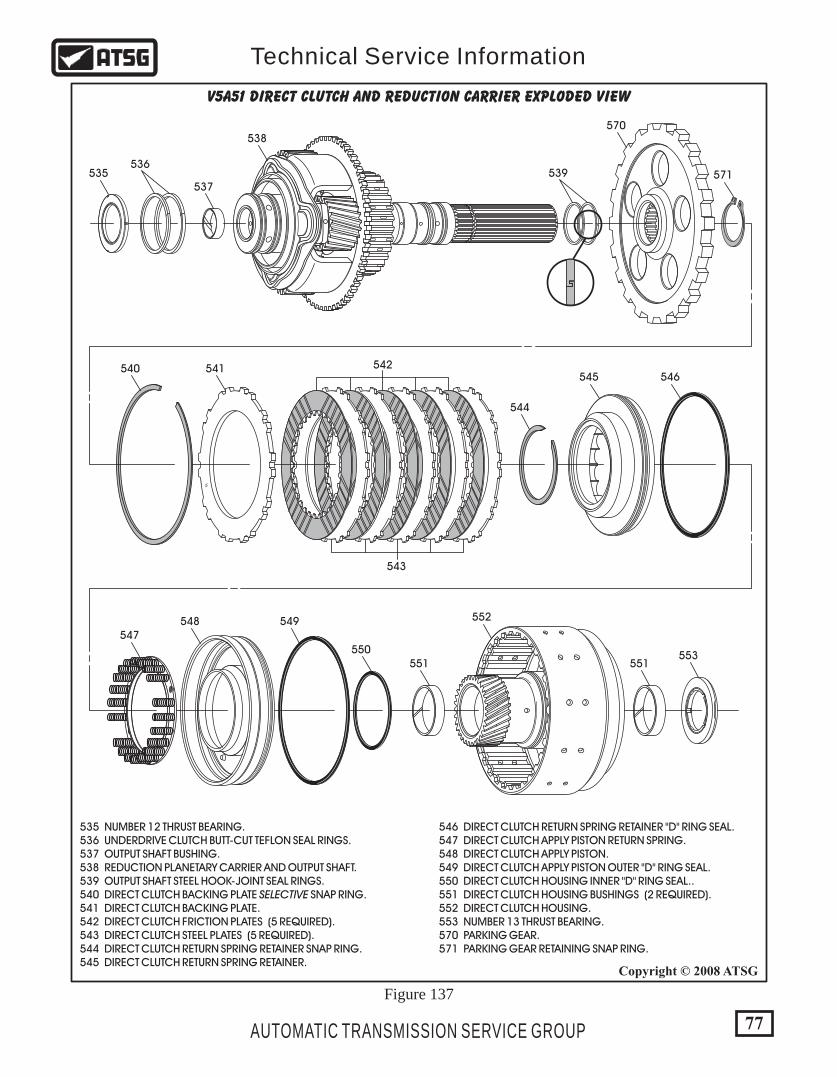
77AUTOMATIC TRANSMISSION SERVICE GROUP
Technical Service Information
Copyright © 2008 ATSG
R
535
540
544
545 546
547548 549
550551 551
552
553
541 542
543
537
538570
571536
539
535 NUMBER 12 THRUST BEARING. 536 UNDERDRIVE CLUTCH BUTT-CUT TEFLON SEAL RINGS. 537 OUTPUT SHAFT BUSHING. 538 REDUCTION PLANETARY CARRIER AND OUTPUT SHAFT. 539 OUTPUT SHAFT STEEL HOOK-JOINT SEAL RINGS. 540 DIRECT CLUTCH BACKING PLATE SELECTIVE SNAP RING. 541 DIRECT CLUTCH BACKING PLATE. 542 DIRECT CLUTCH FRICTION PLATES (5 REQUIRED). 543 DIRECT CLUTCH STEEL PLATES (5 REQUIRED). 544 DIRECT CLUTCH RETURN SPRING RETAINER SNAP RING. 545 DIRECT CLUTCH RETURN SPRING RETAINER.
546 DIRECT CLUTCH RETURN SPRING RETAINER "D" RING SEAL. 547 DIRECT CLUTCH APPLY PISTON RETURN SPRING. 548 DIRECT CLUTCH APPLY PISTON. 549 DIRECT CLUTCH APPLY PISTON OUTER "D" RING SEAL. 550 DIRECT CLUTCH HOUSING INNER "D" RING SEAL.. 551 DIRECT CLUTCH HOUSING BUSHINGS (2 REQUIRED). 552 DIRECT CLUTCH HOUSING. 553 NUMBER 13 THRUST BEARING. 570 PARKING GEAR. 571 PARKING GEAR RETAINING SNAP RING.
V5A51 DIRECT CLUTCH and reduction carrier exploded view
Figure 137
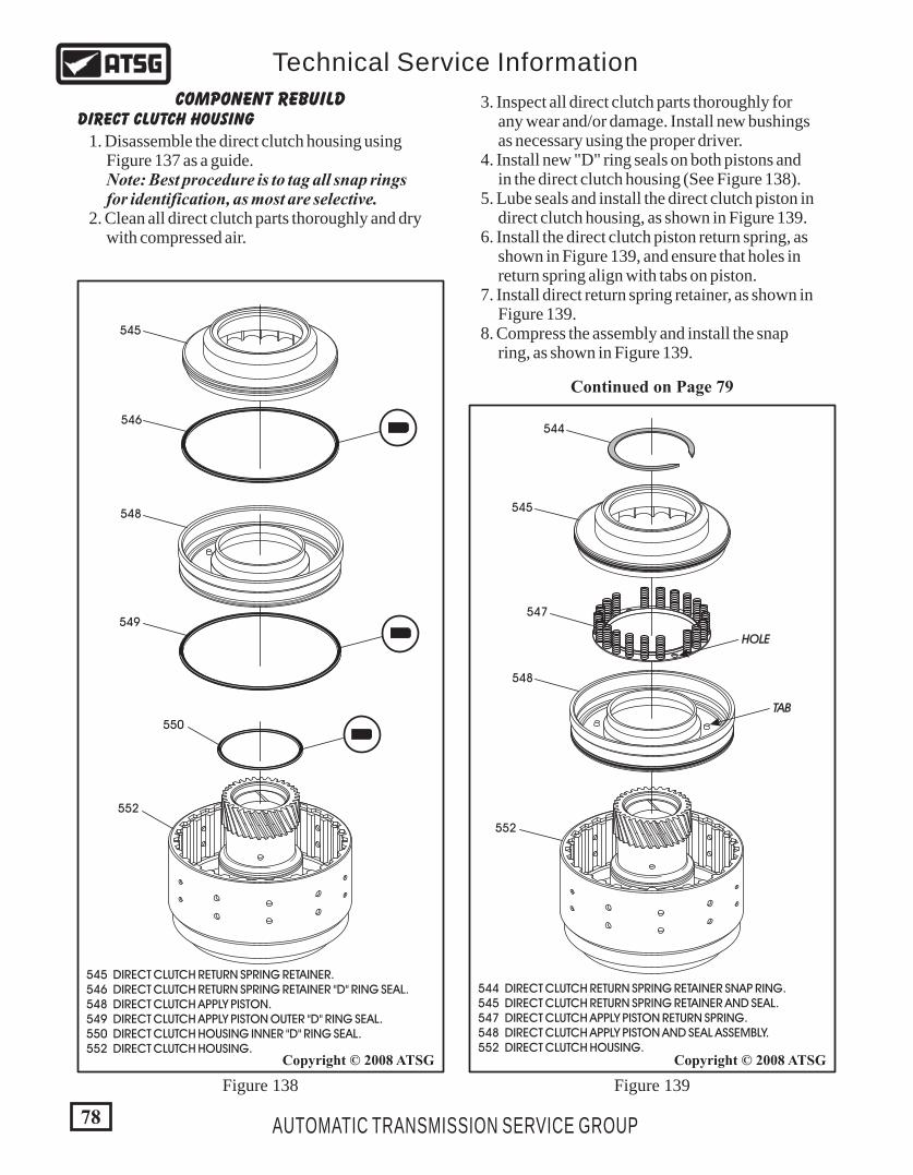
548
545
544
547
HOLE
TAB
552
544 DIRECT CLUTCH RETURN SPRING RETAINER SNAP RING. 545 DIRECT CLUTCH RETURN SPRING RETAINER AND SEAL. 547 DIRECT CLUTCH APPLY PISTON RETURN SPRING. 548 DIRECT CLUTCH APPLY PISTON AND SEAL ASSEMBLY. 552 DIRECT CLUTCH HOUSING.
78
Copyright © 2008 ATSGCopyright © 2008 ATSG
AUTOMATIC TRANSMISSION SERVICE GROUP
Technical Service Information
552
550
548
549
545
546
545 DIRECT CLUTCH RETURN SPRING RETAINER. 546 DIRECT CLUTCH RETURN SPRING RETAINER "D" RING SEAL. 548 DIRECT CLUTCH APPLY PISTON. 549 DIRECT CLUTCH APPLY PISTON OUTER "D" RING SEAL. 550 DIRECT CLUTCH HOUSING INNER "D" RING SEAL. 552 DIRECT CLUTCH HOUSING.
DIRECT CLUTCH HOUSINGCOMPONENT REBUILD
1. Disassemble the direct clutch housing using Figure 137 as a guide. Note: Best procedure is to tag all snap rings for identification, as most are selective. 2. Clean all direct clutch parts thoroughly and dry with compressed air.
3. Inspect all direct clutch parts thoroughly for any wear and/or damage. Install new bushings as necessary using the proper driver. 4. Install new "D" ring seals on both pistons and in the direct clutch housing (See Figure 138). 5. Lube seals and install the direct clutch piston in direct clutch housing, as shown in Figure 139. 6. Install the direct clutch piston return spring, as shown in Figure 139, and ensure that holes in return spring align with tabs on piston. 7. Install direct return spring retainer, as shown in Figure 139. 8. Compress the assembly and install the snap ring, as shown in Figure 139.
Figure 138 Figure 139
Continued on Page 79
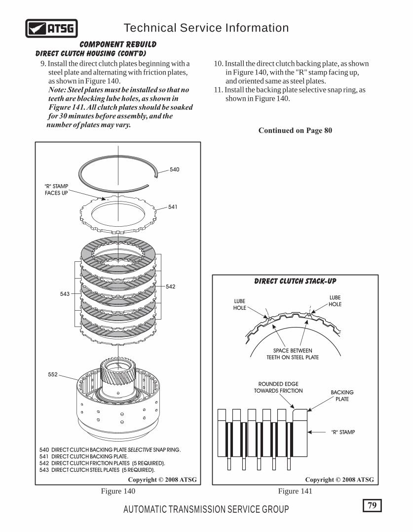
79
Copyright © 2008 ATSG Copyright © 2008 ATSG
AUTOMATIC TRANSMISSION SERVICE GROUP
Technical Service Information
R
552
540
"R" STAMPFACES UP
541
542
543
540 DIRECT CLUTCH BACKING PLATE SELECTIVE SNAP RING. 541 DIRECT CLUTCH BACKING PLATE. 542 DIRECT CLUTCH FRICTION PLATES (5 REQUIRED). 543 DIRECT CLUTCH STEEL PLATES (5 REQUIRED).
DIRECT CLUTCH HOUSING (CONT'D)COMPONENT REBUILD
9. Install the direct clutch plates beginning with a steel plate and alternating with friction plates, as shown in Figure 140. Note: Steel plates must be installed so that no teeth are blocking lube holes, as shown in Figure 141. All clutch plates should be soaked for 30 minutes before assembly, and the number of plates may vary.
10. Install the direct clutch backing plate, as shown in Figure 140, with the "R" stamp facing up, and oriented same as steel plates. 11. Install the backing plate selective snap ring, as shown in Figure 140.
Continued on Page 80
Figure 140 Figure 141
LUBEHOLE
LUBEHOLE
SPACE BETWEENTEETH ON STEEL PLATE
ROUNDED EDGETOWARDS FRICTION BACKING
PLATE
"R" STAMP
DIRECT CLUTCH STACK-UP
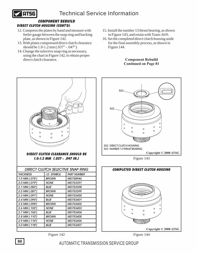
552 DIRECT CLUTCH HOUSING. 553 NUMBER 13 THRUST BEARING.
R
DIRECT CLUTCH SELECTIVE SNAP RINGTHICKNESS
1.9 MM (.075")
2.0 MM (.079")
2.1 MM (.083")
2.2 MM (.087")
2.3 MM (.091")
2.4 MM (.094")
2.5 MM (.098")
2.6 MM (.102")
2.7 MM (.106")
2.8 MM (.110")
2.9 MM (.114")
3.0 MM (.118")
I.D. SYMBOL
BROWN
NONE
BLUE
BROWN
NONE
BLUE
BROWN
NONE
BLUE
BROWN
NONE
BLUE
PART NUMBER
MD758946
MD753397
MD753398
MD753399
MD753400
MD753401
MD753402
MD753403
MD753404
MD753405
MD753406
MD753407
DIRECT CLUTCH CLEARANCE SHOULD BE1.0-1.2 MM (.037 - .047 IN.)
DIRECT CLUTCH HOUSING (CONT'D)COMPONENT REBUILD
12. Compress the plates by hand and measure with feeler gauge between the snap ring and backing plate, as shown in Figure 142. 13. With plates compressed direct clutch clearance should be 1.0-1.2 mm (.037" - .047"). 14. Change the selective snap ring as necessary, using the chart in Figure 142, to obtain proper direct clutch clearance.
15. Install the number 13 thrust bearing, as shown in Figure 143, and retain with Trans-Jel®. 16. Set the completed direct clutch housing aside for the final assembly process, as shown in Figure 144.
Component RebuildContinued on Page 81
80
Copyright © 2008 ATSG
Copyright © 2008 ATSG
AUTOMATIC TRANSMISSION SERVICE GROUP
Technical Service Information
Figure 142 Figure 144
Figure 143
553
552
COMPLETED DIRECT CLUTCH HOUSING
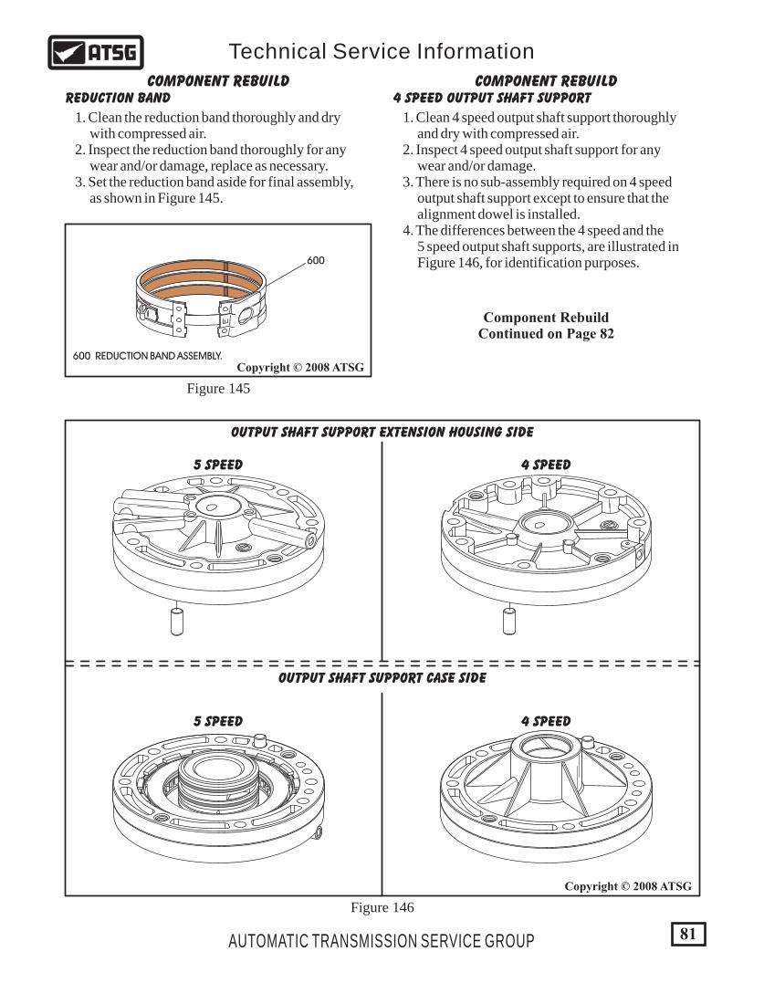
81AUTOMATIC TRANSMISSION SERVICE GROUP
Technical Service Information
Copyright © 2008 ATSG
Copyright © 2008 ATSG
OUTPUT SHAFT SUPPORT EXTENSION HOUSING SIDE
5 SPEED
5 SPEED
4 SPEED
4 SPEED
OUTPUT SHAFT SUPPORT CASE SIDE
600
REDUCTION BAND 4 SPEED OUTPUT SHAFT SUPPORTCOMPONENT REBUILD COMPONENT REBUILD
Figure 145
Figure 146
1. Clean the reduction band thoroughly and dry with compressed air. 2. Inspect the reduction band thoroughly for any wear and/or damage, replace as necessary. 3. Set the reduction band aside for final assembly, as shown in Figure 145.
1. Clean 4 speed output shaft support thoroughly and dry with compressed air. 2. Inspect 4 speed output shaft support for any wear and/or damage. 3. There is no sub-assembly required on 4 speed output shaft support except to ensure that the alignment dowel is installed. 4. The differences between the 4 speed and the 5 speed output shaft supports, are illustrated in Figure 146, for identification purposes.
600 REDUCTION BAND ASSEMBLY.
Component RebuildContinued on Page 82
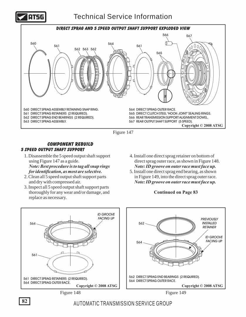
82 AUTOMATIC TRANSMISSION SERVICE GROUP
Technical Service Information
565
560561 561
561
566 567
562 562563
564
564
DIRECT SPRAG AND 5 SPEED OUTPUT SHAFT SUPPORT EXPLODED VIEW
561 DIRECT SPRAG RETAINERS (2 REQUIRED). 564 DIRECT SPRAG OUTER RACE.
564 DIRECT SPRAG OUTER RACE. 565 DIRECT CLUTCH STEEL "HOOK-JOINT" SEALING RINGS. 566 REAR TRANSMISSION SUPPORT ALIGNMENT DOWEL. 567 REAR OUTPUT SHAFT SUPPORT (5 SPEED).
560 DIRECT SPRAG ASSEMBLY RETAINING SNAP RING. 561 DIRECT SPRAG RETAINERS (2 REQUIRED). 562 DIRECT SPRAG END BEARINGS (2 REQUIRED). 563 DIRECT SPRAG ASSEMBLY.
562 DIRECT SPRAG END BEARINGS (2 REQUIRED). 564 DIRECT SPRAG OUTER RACE.
562
564
PREVIOUSLYINSTALLEDRETAINER
ID GROOVEFACING UP
ID GROOVEFACING UP
Copyright © 2008 ATSGCopyright © 2008 ATSG
Copyright © 2008 ATSG
Figure 147
Figure 148 Figure 149
5 SPEED OUTPUT SHAFT SUPPORTCOMPONENT REBUILD
1. Disassemble the 5 speed output shaft support using Figure 147 as a guide. Note: Best procedure is to tag all snap rings for identification, as most are selective. 2. Clean all 5 speed output shaft support parts and dry with compressed air. 3. Inspect all 5 speed output shaft support parts thoroughly for any wear and/or damage, and replace as necessary.
Continued on Page 83
4. Install one direct sprag retainer on bottom of direct sprag outer race, as shown in Figure 148. Note: ID groove on outer race must face up. 5. Install one direct sprag end bearing, as shown in Figure 149, into the direct sprag outer race. Note: ID groove on outer race must face up.

83AUTOMATIC TRANSMISSION SERVICE GROUP
Technical Service Information
565
567
565 DIRECT CLUTCH STEEL "HOOK-JOINT" SEALING RINGS. 567 REAR OUTPUT SHAFT SUPPORT (5 SPEED).
560
564566
567
560 DIRECT SPRAG ASSEMBLY RETAINING SNAP RING. 564 COMPLETED DIRECT SPRAG ASSEMBLY. 566 REAR TRANSMISSION SUPPORT ALIGNMENT DOWEL. 567 REAR OUTPUT SHAFT SUPPORT (5 SPEED).
Copyright © 2008 ATSG
Copyright © 2008 ATSG
Figure 150 Figure 152
Figure 151
561 DIRECT SPRAG RETAINERS (2 REQUIRED). 562 DIRECT SPRAG END BEARINGS (2 REQUIRED). 563 DIRECT SPRAG ASSEMBLY. 564 DIRECT SPRAG OUTER RACE.
561
562
563
564
ID GROOVEFACING UP
"LIP" ON SPRAGFACES DOWN
Copyright © 2008 ATSG
5 SPEED OUTPUT SHAFT SUPPORT (CONT'D)COMPONENT REBUILD
Continued on Page 84
6. Install the direct sprag assembly into the outer race, as shown in Figure 150, with the "lip" on sprag cage facing down. Note: The direct sprag cage has no arrows on it to help with direction of installation. The "lip" must face down, with the ID groove on the race facing up, as shown in Figure 150. 7. Install the second direct sprag end bearing, as shown in Figure 150, with the smooth side facing up. 8. Install the second direct sprag retainer by snapping it over the lip on the outer race, as shown in Figure 150. 9. Install the completed direct sprag assembly, as shown in Figure 151, into the output shaft support with ID groove facing up. 10. Install the direct sprag assembly retaining snap ring, as shown in Figure 151. 11. Install the alignment dowel, if removed, into output shaft support, as shown in Figure 151. 12. Install the two direct clutch, steel, hook-joint sealing rings, as shown in Figure 152.

COMPLETED OUTPUT SHAFT SUPPORTAND DIRECT SPRAG ASSEMBLY
5 SPEED
Copyright © 2008 ATSG
Copyright © 2008 ATSG
Copyright © 2008 ATSG
R
5 SPEED OUTPUT SHAFT SUPPORT (CONT'D)COMPONENT REBUILD DIRECT CLUTCH HOUSING SHOULD
FREEWHEEL CLOCKWISE AND LOCKCOUNTER-CLOCKWISE WHILE HOLDING
OUTPUT SHAFT SUPPORT
Component RebuildContinued on Page 85
13. Install the completed direct clutch housing onto the completed output shaft support, as shown in Figure 153. 14. The direct clutch housing should freewheel clockwise, and lock counter-clockwise, as shown in Figure 154. Note: There are two ways to mis-assemble the direct sprag. Proper assembly is as follows; 1. The sprag cage must go into the outer race with the "lip" facing down, while the ID groove on the race is facing up. 2. The completed direct sprag assembly must go into the rear support with the ID groove facing up. 15. Set the completed output shaft support aside for the final assembly process (See Figure 155).
R
FR LEEWHEE
Figure 153
Figure 155
Figure 154
84 AUTOMATIC TRANSMISSION SERVICE GROUP
Technical Service Information
Turn
Hold
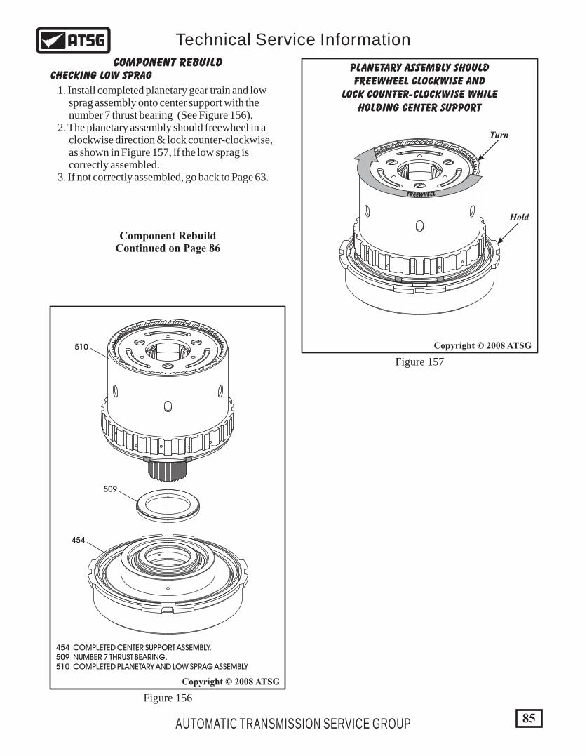
85
Copyright © 2008 ATSG
Copyright © 2008 ATSG
AUTOMATIC TRANSMISSION SERVICE GROUP
Technical Service Information
CHECKING LOW SPRAGCOMPONENT REBUILD PLANETARY ASSEMBLY SHOULD
FREEWHEEL CLOCKWISE ANDLOCK COUNTER-CLOCKWISE WHILE
HOLDING CENTER SUPPORT
509
454
510
454 COMPLETED CENTER SUPPORT ASSEMBLY. 509 NUMBER 7 THRUST BEARING. 510 COMPLETED PLANETARY AND LOW SPRAG ASSEMBLY
FR LEEWHEE
1. Install completed planetary gear train and low sprag assembly onto center support with the number 7 thrust bearing (See Figure 156). 2. The planetary assembly should freewheel in a clockwise direction & lock counter-clockwise, as shown in Figure 157, if the low sprag is correctly assembled. 3. If not correctly assembled, go back to Page 63.
Figure 156
Figure 157
Component RebuildContinued on Page 86
Turn
Hold
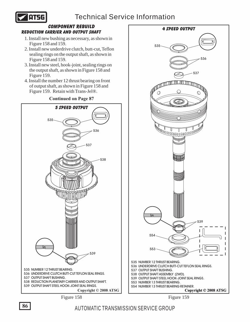
86
Copyright © 2008 ATSG
AUTOMATIC TRANSMISSION SERVICE GROUP
Technical Service Information
535 NUMBER 12 THRUST BEARING. 536 UNDERDRIVE CLUTCH BUTT-CUT TEFLON SEAL RINGS. 537 OUTPUT SHAFT BUSHING. 538 OUTPUT SHAFT ASSEMBLY (2WD). 539 OUTPUT SHAFT STEEL HOOK-JOINT SEAL RINGS. 553 NUMBER 13 THRUST BEARING. 554 NUMBER 13 THRUST BEARING RETAINER.
Copyright © 2008 ATSGCopyright © 2008 ATSG
553
554
535 NUMBER 12 THRUST BEARING. 536 UNDERDRIVE CLUTCH BUTT-CUT TEFLON SEAL RINGS. 537 OUTPUT SHAFT BUSHING. 538 REDUCTION PLANETARY CARRIER AND OUTPUT SHAFT. 539 OUTPUT SHAFT STEEL HOOK-JOINT SEAL RINGS.
535
535
536
536
537
537
538
539
539
5 SPEED OUTPUT
4 SPEED OUTPUT
Figure 158 Figure 159
REDUCTION CARRIER AND OUTPUT SHAFTCOMPONENT REBUILD
1. Install new bushing as necessary, as shown in Figure 158 and 159. 2. Install new underdrive clutch, butt-cut, Teflon sealing rings on the output shaft, as shown in Figure 158 and 159. 3. Install new steel, hook-joint, sealing rings on the output shaft, as shown in Figure 158 and Figure 159. 4. Install the number 12 thrust bearing on front of output shaft, as shown in Figure 158 and Figure 159. Retain with Trans-Jel®.
Continued on Page 87
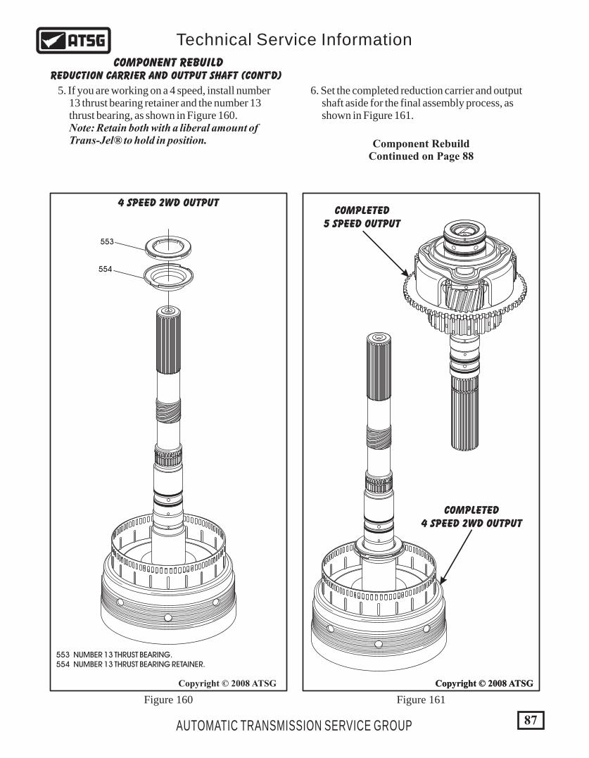
87AUTOMATIC TRANSMISSION SERVICE GROUP
Technical Service Information
Copyright © 2008 ATSGCopyright © 2008 ATSGCopyright © 2008 ATSG
553 NUMBER 13 THRUST BEARING. 554 NUMBER 13 THRUST BEARING RETAINER.
4 SPEED 2WD OUTPUT
COMPLETED4 SPEED 2WD OUTPUT
COMPLETED5 SPEED OUTPUT
553
554
Figure 160 Figure 161
5. If you are working on a 4 speed, install number 13 thrust bearing retainer and the number 13 thrust bearing, as shown in Figure 160. Note: Retain both with a liberal amount of Trans-Jel® to hold in position.
REDUCTION CARRIER AND OUTPUT SHAFT (CONT'D)COMPONENT REBUILD
6. Set the completed reduction carrier and output shaft aside for the final assembly process, as shown in Figure 161.
Component RebuildContinued on Page 88
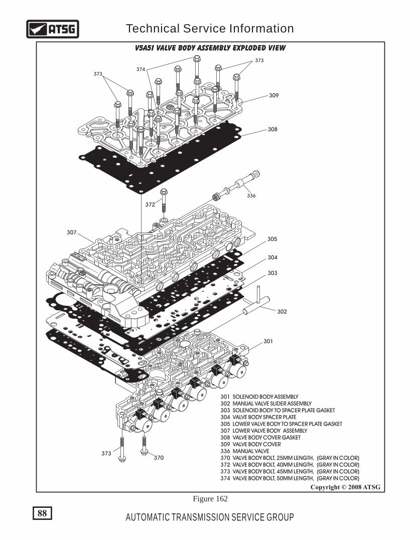
180X
6
00
- 2777
301
370373
302
303
304
305
372
308
309
307
301 SOLENOID BODY ASSEMBLY 302 MANUAL VALVE SLIDER ASSEMBLY 303 SOLENOID BODY TO SPACER PLATE GASKET 304 VALVE BODY SPACER PLATE 305 LOWER VALVE BODY TO SPACER PLATE GASKET 307 LOWER VALVE BODY ASSEMBLY 308 VALVE BODY COVER GASKET 309 VALVE BODY COVER 336 MANUAL VALVE 370 VALVE BODY BOLT, 25MM LENGTH, (GRAY IN COLOR) 372 VALVE BODY BOLT, 40MM LENGTH, (GRAY IN COLOR) 373 VALVE BODY BOLT, 45MM LENGTH, (GRAY IN COLOR) 374 VALVE BODY BOLT, 50MM LENGTH, (GRAY IN COLOR)
336
373
373
374
V5A51 VALVE BODY ASSEMBLY EXPLODED VIEW
88
Copyright © 2008 ATSG
AUTOMATIC TRANSMISSION SERVICE GROUP
Technical Service Information
Figure 162
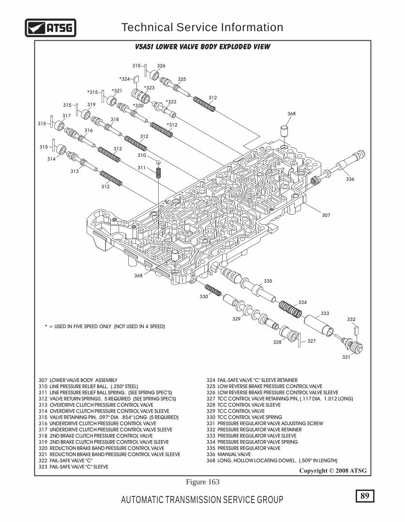
307 LOWER VALVE BODY ASSEMBLY 310 LINE PRESSURE RELIEF BALL, (.250" STEEL) 311 LINE PRESSURE RELIEF BALL SPRING, (SEE SPRING SPEC'S) 312 VALVE RETURN SPRINGS, 5 REQUIRED (SEE SPRING SPECS) 313 OVERDRIVE CLUTCH PRESSURE CONTROL VALVE 314 OVERDRIVE CLUTCH PRESSURE CONTROL VALVE SLEEVE 315 VALVE RETAINING PIN, .097" DIA .854" LONG (5 REQUIRED) 316 UNDERDRIVE CLUTCH PRESSURE CONTROL VALVE 317 UNDERDRIVE CLUTCH PRESSURE CONTROL VALVE SLEEVE 318 2ND BRAKE CLUTCH PRESSURE CONTROL VALVE 319 2ND BRAKE CLUTCH PRESSURE CONTROL VALVE SLEEVE 320 REDUCTION BRAKE BAND PRESSURE CONTROL VALVE 321 REDUCTION BRAKE BAND PRESSURE CONTROL VALVE SLEEVE 322 FAIL-SAFE VALVE "C" 323 FAIL-SAFE VALVE "C" SLEEVE
324 FAIL-SAFE VALVE "C" SLEEVE RETAINER 325 LOW REVERSE BRAKE PRESSURE CONTROL VALVE 326 LOW REVERSE BRAKE PRESSURE CONTROL VALVE SLEEVE 327 TCC CONTROL VALVE RETAINING PIN, (.117 DIA. 1.012 LONG) 328 TCC CONTROL VALVE SLEEVE 329 TCC CONTROL VALVE 330 TCC CONTROL VALVE SPRING 331 PRESSURE REGULATOR VALVE ADJUSTING SCREW 332 PRESSURE REGULATOR VALVE RETAINER 333 PRESSURE REGULATOR VALVE SLEEVE 334 PRESSURE REGULATOR VALVE SPRING 335 PRESSURE REGULATOR VALVE 336 MANUAL VALVE 368 LONG, HOLLOW LOCATING DOWEL, (.509" IN LENGTH)
307
336
368
368
* = USED IN FIVE SPEED ONLY (NOT USED IN 4 SPEED)
327
330
333
334
335
331
332329
328
310
311
312
312
312
*312
312
313
314
315
315
315
*315
*324
315
316
317318
319 *320
*321
*322
325
326
*323
V5A51 LOWER VALVE BODY EXPLODED VIEW
89
Copyright © 2008 ATSG
AUTOMATIC TRANSMISSION SERVICE GROUP
Technical Service Information
Figure 163

301 SOLENOID BODY ASSEMBLY 302 MANUAL VALVE SLIDER ASSEMBLY 324 SWITCHING VALVE BORE PLUG RETAINER 332 VALVE RETAINER (3 REQUIRED) 337 SWITCHING VALVE 338 SWITCHING VALVE BORE PLUG 339 FAIL-SAFE VALVE "A1" 340 FAIL-SAFE VALVE "A" SPRING 341 FAIL-SAFE VALVE "A2" 342 FAIL-SAFE VALVE "A" SLEEVE 343 FAIL-SAFE VALVE "B" 344 FAIL-SAFE VALVE "B" SLEEVE 345 TCC PRESSURE CONTROL VALVE SPRING 346 TCC PRESSURE CONTROL VALVE 347 TCC PRESSURE CONTROL VALVE BORE PLUG 348 SMALL SOLENOID "O" RING (1 REQUIRED ON EACH SOL.) 349 MEDIUM SOLENOID "O" RING (1 REQUIRED ON EACH SOL.) 350 LARGE SOLENOID "O" RING (1 REQUIRED ON EACH SOL.) 351 LOW REVERSE BRAKE/DIRECT CLUTCH SOLENOID 352 REDUCTION BRAKE SOLENOID (5 SPEED ONLY) 353 2ND BRAKE SOLENOID 354 UNDERDRIVE CLUTCH SOLENOID 355 OVERDRIVE CLUTCH SOLENOID 356 TORQUE CONVERTER CLUTCH SOLENOID 357 SOLENOID RETAINING BRACKET 358 SOLENOID RETAINING BRACKET BOLTS (7 REQUIRED) 359 UNDERDRIVE CLUTCH CHECKBALL 360 OVERDRIVE CLUTCH CHECKBALL 361 REVERSE CLUTCH CHECKBALL 362 CHECKBALL SPRINGS (3 REQUIRED) 363 LOW REVERSE SHUTTLE BALL, (.250" RUBBER)
337
338
339
340
341
342
343
344
345
346
347
348
350
*352
353
354
355
356
357358
358
358
358
358
358
358
351
349
301
302
324332
332
332
367359
360
361
362
363 364
365
366
367
V5A51 SOLENOID BODY EXPLODED VIEW 364 LOW REVERSE BRAKE ACCUMULATOR SPRING 365 LOW REVERSE BRAKE ACCUMULATOR 366 LOW REVERSE BRAKE ACCUMULATOR SCARF-CUT SEAL RING 367 SHORT, HOLLOW LOCATING DOWEL, (.351" IN LENGTH)
* = USED IN FIVE SPEED ONLY (NOT USED IN 4 SPEED)
90
Copyright © 2008 ATSG
AUTOMATIC TRANSMISSION SERVICE GROUP
Technical Service Information
Figure 164

311
310
359360
361364
363
365
366
362(3 USED)
310 LINE PRESSURE RELIEF BALL, .250" STEEL 311 LINE PRESSURE RELIEF SPRING 359 UNDERDRIVE CLUTCH BALL AND SPRING, 250" STEEL 360 OVERDRIVE CLUTCH BALL AND SPRING, 250" STEEL 361 REVERSE CLUTCH BALL AND SPRING, 250" STEEL
362 SPRING FOR 3 STEEL BALLS, ALL THE SAME 363 LOW/REVERSE SHUTTLE BALL, .250" RUBBER 364 LOW/REVERSE BRAKE ACCUMULATOR SPRING 365 LOW/REVERSE BRAKE ACCUMULATOR 366 LOW/REVERSE BRAKE ACCUM. "SCARF-CUT" SEAL RING
Lower Valve Body
Solenoid Valve Body
R/V4A51 & V5A 51 VALVE BODY CHECK BALL AND RETAINER LOCATIONS
}
These Two RetainersUsed In 5 Speed Only
91
Copyright © 2008 ATSG
AUTOMATIC TRANSMISSION SERVICE GROUP
Technical Service Information
Figure 165
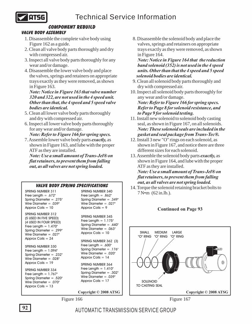
SPRING NUMBER 364Free Length = 1.410"Spring Diameter = .302"Wire Diameter = .039"Approx Coils = 17
SPRING NUMBER 362 (3)Free Length = .600"Spring Diameter = .176"Wire Diameter = .020"Approx Coils = 14
SPRING NUMBER 311Free Length = .672"Spring Diameter = .275"Wire Diameter = .039"Approx Coils = 10
SPRING NUMBER 334Free Length = 1.767"Spring Diameter = .520"Wire Diameter = .070"Approx Coils = 13
SPRING NUMBER 330Free Length = 1.094"Spring Diameter = .232"Wire Diameter = .028"Approx Coils = 19
SPRING NUMBER 340Free Length = .862"Spring Diameter = .349"Wire Diameter = .027"Approx Coils = 9
SPRING NUMBER 345Free Length = 1.175"Spring Diameter = .440"Wire Diameter = .063"Approx Coils = 10
SPRING NUMBER 312(5 USED IN FIVE SPEED)(4 USED IN FOUR SPEED)Free Length = 1.470"Spring Diameter = .299"Wire Diameter = .027"Approx Coils = 24
VALVE BODY SPRING SPECIFICATIONS
Figure 166 Figure 167
COMPONENT REBUILDVALVE BODY ASSEMBLY
1. Disassemble the complete valve body using Figure 162 as a guide. 2. Clean all valve body parts thoroughly and dry with compressed air. 3. Inspect all valve body parts thoroughly for any wear and/or damage. 4. Disassemble the lower valve body and place the valves, springs and retainers on appropriate trays exactly as they were removed, as shown in Figure 163. Note: Notice in Figure 163 that valve number 320 and 322, are not used in the 4 speed unit. Other than that, the 4 speed and 5 speed valve bodies are identical. 5. Clean all lower valve body parts thoroughly and dry with compressed air. 6. Inspect all lower valve body parts thoroughly for any wear and/or damage. Note: Refer to Figure 166 for spring specs. 7. Assemble lower valve body parts exactly, as shown in Figure 163, and lube with the proper ATF as they are installed. Note: Use a small amount of Trans-Jel® on flat retainers, to prevent them from falling out, as all valves are not spring loaded.
8. Disassemble the solenoid body and place the valves, springs and retainers on appropriate trays exactly as they were removed, as shown in Figure 164. Note: Notice in Figure 164 that the reduction band solenoid (352) is not used in the 4 speed units. Other than that the 4 speed and 5 speed solenoid bodies are identical. 9. Clean all solenoid body parts thoroughly and dry with compressed air. 10. Inspect all solenoid body parts thoroughly for any wear and/or damage. Note: Refer to Figure 166 for spring specs. Refer to Page 8 for solenoid resistance, and to Page 9 for solenoid testing. 11. Install new solenoid to solenoid body casting seal, as shown in Figure 167, on all solenoids. Note: These solenoid seals are included in the gasket and seal package from Trans-Tec®. 12. Install 3 new "O" rings on each solenoid, as shown in Figure 167, and notice there are three different sizes for each solenoid. 13. Assemble the solenoid body parts exactly, as shown in Figure 164, and lube with the proper ATF as they are installed. Note: Use a small amount of Trans-Jel® on flat retainers, to prevent them from falling out, as all valves are not spring loaded. 14. Torque the solenoid retaining bracket bolts to 7 N•m (62 in.lb.).
SMALL"O" RING
MEDIUM"O" RING
LARGE"O" RING
SOLENOIDTO CASTING SEAL
Continued on Page 93
92
Copyright © 2008 ATSGCopyright © 2008 ATSG
AUTOMATIC TRANSMISSION SERVICE GROUP
Technical Service Information
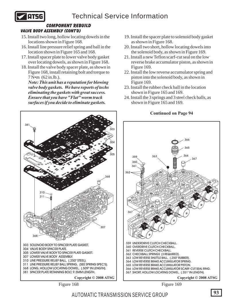
367359
360
361
362
363 364
365
366
367
359 UNDERDRIVE CLUTCH CHECKBALL. 360 OVERDRIVE CLUTCH CHECKBALL. 361 REVERSE CLUTCH CHECKBALL. 362 CHECKBALL SPRINGS (3 REQUIRED). 363 LOW REVERSE SHUTTLE BALL, (.250" RUBBER). 364 LOW REVERSE BRAKE ACCUMULATOR SPRING. 365 LOW REVERSE BRAKE ACCUMULATOR PISTON. 366 LOW REVERSE BRAKE ACCUMULATOR SCARF-CUT SEAL RING. 367 SHORT, HOLLOW LOCATING DOWEL, (.351" IN LENGTH).
381
304
305
368
310
311
307
368
303
303 SOLENOID BODY TO SPACER PLATE GASKET. 304 VALVE BODY SPACER PLATE. 305 LOWER VALVE BODY TO SPACER PLATE GASKET. 307 LOWER VALVE BODY ASSEMBLY. 310 LINE PRESSURE RELIEF BALL, (.250" STEEL). 311 LINE PRESSURE RELIEF BALL SPRING, (SEE SPRING SPEC'S). 368 LONG, HOLLOW LOCATING DOWEL, (.509" IN LENGTH). 381 SPACER PLATE RETAINING BOLT, 9.5MM LENGTH.
93
Copyright © 2008 ATSGCopyright © 2008 ATSG
AUTOMATIC TRANSMISSION SERVICE GROUP
Technical Service Information
Figure 168 Figure 169
COMPONENT REBUILDVALVE BODY ASSEMBLY (CONT'D)
15. Install two long, hollow locating dowels in the locations shown in Figure 168. 16. Install line pressure relief spring and ball in the location shown in Figure 165 and 168. 17. Install spacer plate to lower valve body gasket over locating dowels, as shown in Figure 168. 18. Install the valve body spacer plate, as shown in Figure 168, install retaining bolt and torque to 7 N•m (62 in.lb.). Note: This unit has a reputation for blowing valve body gaskets. We have reports of techs eliminating the gaskets with great success. Ensure that you have "Flat" worm track surfaces if you decide to eliminate gaskets.
19. Install the spacer plate to solenoid body gasket as shown in Figure 168. 20. Install two short, hollow locating dowels into the solenoid body, as shown in Figure 169. 21. Install a new Teflon scarf-cut seal on the low reverse brake accumulator piston, as shown in Figure 169. 22. Install the low reverse accumulator spring and piston into the solenoid body, as shown in Figure 169. 23. Install the rubber check ball in the location shown in Figure 165 and 169. 24. Install the 3 springs and 3 steel check balls, as shown in Figure 165 and 169.
Continued on Page 94
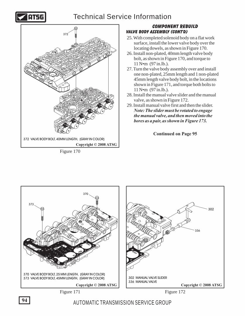
180X
372
372 VALVE BODY BOLT, 40MM LENGTH, (GRAY IN COLOR)
370
373
180X
370 VALVE BODY BOLT, 25 MM LENGTH, (GRAY IN COLOR) 373 VALVE BODY BOLT, 45MM LENGTH, (GRAY IN COLOR)
COMPONENT REBUILDVALVE BODY ASSEMBLY (CONT'D)
25. With completed solenoid body on a flat work surface, install the lower valve body over the locating dowels, as shown in Figure 170. 26. Install non-plated, 40mm length valve body bolt, as shown in Figure 170, and torque to 11 N•m (97 in.lb.). 27. Turn the valve body assembly over and install one non-plated, 25mm length and 1 non-plated 45mm length valve body bolt, in the locations shown in Figure 171, and torque both bolts to 11 N•m (97 in.lb.). 28. Install the manual valve slider and the manual valve, as shown in Figure 172. 29. Install manual valve first and then the slider. Note: The slider must be rotated to engage the manual valve, and then moved into the bores as a pair, as shown in Figure 173.
Continued on Page 95
94
Copyright © 2008 ATSGCopyright © 2008 ATSG
Copyright © 2008 ATSG
AUTOMATIC TRANSMISSION SERVICE GROUP
Technical Service Information
Figure 170
Figure 171 Figure 172
302 MANUAL VALVE SLIDER 336 MANUAL VALVE
302
336
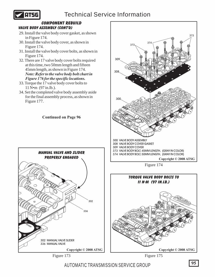
302 MANUAL VALVE SLIDER 336 MANUAL VALVE
336
302
MANUAL VALVE AND SLIDERPROPERLY ENGAGED
95
Copyright © 2008 ATSG
Copyright © 2008 ATSG
Copyright © 2008 ATSG
AUTOMATIC TRANSMISSION SERVICE GROUP
Technical Service Information
180X
6
00
- 2777
TORQUE VALVE BODY BOLTS TO11 N·M (97 IN.LB.)
300 VALVE BODY ASSEMBLY 308 VALVE BODY COVER GASKET 309 VALVE BODY COVER 373 VALVE BODY BOLT, 45MM LENGTH, (GRAY IN COLOR) 374 VALVE BODY BOLT, 50MM LENGTH, (GRAY IN COLOR)
180X
308
300
309
373
373
374
6
00
- 2777
COMPONENT REBUILDVALVE BODY ASSEMBLY (CONT'D)
29. Install the valve body cover gasket, as shown in Figure 174. 30. Install the valve body cover, as shown in Figure 174. 31. Install the valve body cover bolts, as shown in Figure 174. 32. There are 17 valve body cover bolts required at this time, two 50mm length and fifteen 45mm length, as shown in Figure 174. Note: Refer to the valve body bolt chart in Figure 176 for the specific locations. 33. Torque the 17 valve body cover bolts to 11 N•m (97 in.lb.). 34. Set the completed valve body assembly aside for the final assembly process, as shown in Figure 177.
Continued on Page 96
Figure 173 Figure 175
Figure 174
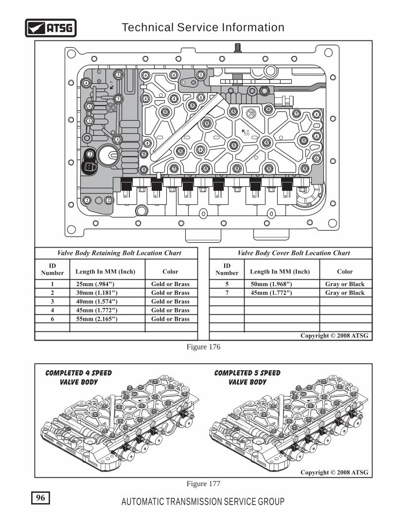
Copyright © 2008 ATSG
IDNumber
1 Gold or Brass25mm (.984")
2 Gold or Brass30mm (1.181")
3 Gold or Brass40mm (1.574")
4 Gold or Brass45mm (1.772")
6 Gold or Brass55mm (2.165")
Length In MM (Inch) Color
Valve Body Retaining Bolt Location Chart
IDNumber
5 Gray or Black50mm (1.968")
7 Gray or Black45mm (1.772")
Length In MM (Inch) Color
Valve Body Cover Bolt Location Chart
006
0X18
- 2
1
2
2 2
3
3
3
4
4
4
4
4
4
47
7
55
5
5
5 5 5 5
55
5
5
5
5
5
4
6
4
4
3
3
- 2777
96 AUTOMATIC TRANSMISSION SERVICE GROUP
Technical Service Information
Figure 176
Figure 177
180X
6
00
- 2777
180X
6
00
- 2777
COMPLETED 5 SPEEDVALVE BODY
COMPLETED 4 SPEEDVALVE BODY
Copyright © 2008 ATSG
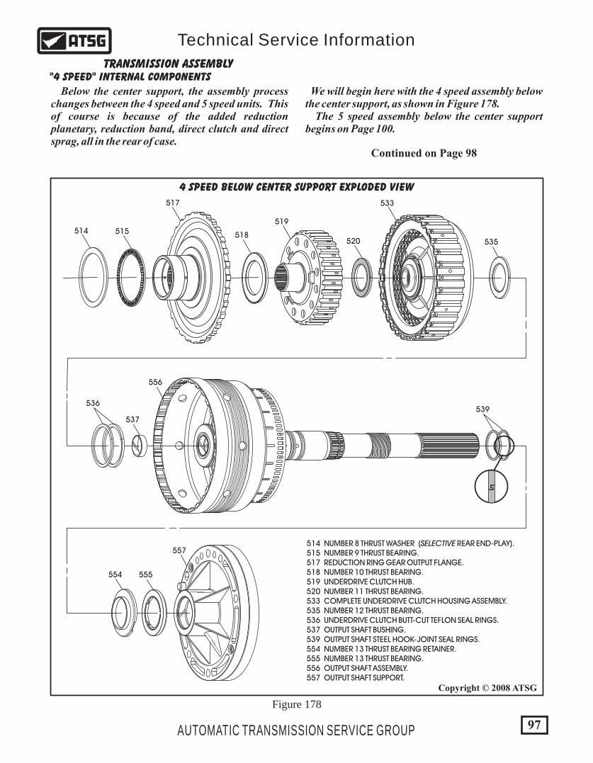
97AUTOMATIC TRANSMISSION SERVICE GROUP
Technical Service Information
Copyright © 2008 ATSG
"4 SPEED" INTERNAL COMPONENTSTRANSMISSION ASSEMBLY
Below the center support, the assembly process changes between the 4 speed and 5 speed units. This of course is because of the added reduction planetary, reduction band, direct clutch and direct sprag, all in the rear of case.
We will begin here with the 4 speed assembly below the center support, as shown in Figure 178. The 5 speed assembly below the center support begins on Page 100.
514 NUMBER 8 THRUST WASHER (SELECTIVE REAR END-PLAY). 515 NUMBER 9 THRUST BEARING. 517 REDUCTION RING GEAR OUTPUT FLANGE. 518 NUMBER 10 THRUST BEARING. 519 UNDERDRIVE CLUTCH HUB. 520 NUMBER 11 THRUST BEARING. 533 COMPLETE UNDERDRIVE CLUTCH HOUSING ASSEMBLY. 535 NUMBER 12 THRUST BEARING. 536 UNDERDRIVE CLUTCH BUTT-CUT TEFLON SEAL RINGS. 537 OUTPUT SHAFT BUSHING. 539 OUTPUT SHAFT STEEL HOOK-JOINT SEAL RINGS. 554 NUMBER 13 THRUST BEARING RETAINER. 555 NUMBER 13 THRUST BEARING. 556 OUTPUT SHAFT ASSEMBLY. 557 OUTPUT SHAFT SUPPORT.
517
515514
520
519
518
533
535
537
556
536539
555
557
554
4 SPEED BELOW CENTER SUPPORT EXPLODED VIEW
Continued on Page 98
Figure 178
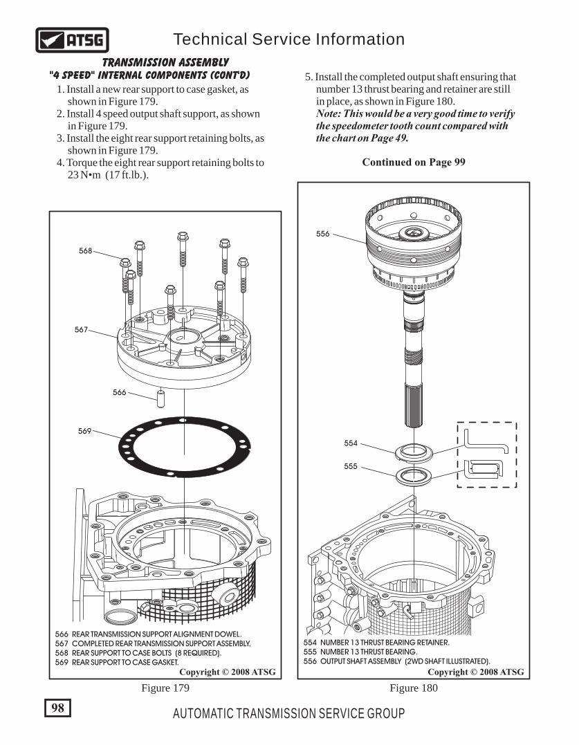
98 AUTOMATIC TRANSMISSION SERVICE GROUP
Technical Service Information
566 REAR TRANSMISSION SUPPORT ALIGNMENT DOWEL. 567 COMPLETED REAR TRANSMISSION SUPPORT ASSEMBLY. 568 REAR SUPPORT TO CASE BOLTS (8 REQUIRED). 569 REAR SUPPORT TO CASE GASKET.
568
566
567
569
Figure 179
Copyright © 2008 ATSG
555
556
554
554 NUMBER 13 THRUST BEARING RETAINER. 555 NUMBER 13 THRUST BEARING. 556 OUTPUT SHAFT ASSEMBLY (2WD SHAFT ILLUSTRATED).
Figure 180
Copyright © 2008 ATSG
"4 SPEED" INTERNAL COMPONENTS (CONT'D)TRANSMISSION ASSEMBLY
1. Install a new rear support to case gasket, as shown in Figure 179. 2. Install 4 speed output shaft support, as shown in Figure 179. 3. Install the eight rear support retaining bolts, as shown in Figure 179. 4. Torque the eight rear support retaining bolts to 23 N•m (17 ft.lb.).
5. Install the completed output shaft ensuring that number 13 thrust bearing and retainer are still in place, as shown in Figure 180. Note: This would be a very good time to verify the speedometer tooth count compared with the chart on Page 49.
Continued on Page 99

99AUTOMATIC TRANSMISSION SERVICE GROUP
Technical Service Information
519
520
518
533
535
518 NUMBER 10 THRUST BEARING. 519 UNDERDRIVE CLUTCH HUB. 520 NUMBER 11 THRUST BEARING. 533 COMPLETE UNDERDRIVE CLUTCH HOUSING ASSEMBLY. 535 NUMBER 12 THRUST BEARING.
Figure 181
Continued on Page 100
Copyright © 2008 ATSG
"4 SPEED" INTERNAL COMPONENTS (CONT'D)TRANSMISSION ASSEMBLY
514
515
517
514 NUMBER 8 THRUST WASHER (SELECTIVE REAR END-PLAY). 515 NUMBER 9 THRUST BEARING. 517 OUTPUT FLANGE.
Figure 182
6. Verify that the number 12 thrust bearing is still in place on the output shaft (See Figure 181). 7. Install completed underdrive clutch housing, as shown in Figure 181. 8. Install the number 11 thrust bearing onto the underdrive clutch housing and retain with a small amount of Trans-Jel® (See Figure 181).
9. Install the underdrive clutch hub, as shown in Figure 181, by rotating back and forth until it is fully seated. 10. Install the number 10 thrust bearing onto the underdrive clutch hub, as shown in Figure 181. 11. Install the output flange into the splines of the output shaft, as shown in Figure 182. 12. Install the number 9 thrust bearing over the hub of the output flange, as shown in Figure 182. 13. Install the number 8 selective thrust washer on top of the number 9 thrust bearing, as shown in Figure 182. Note: You are now ready to check rear end clearance and install center support which is the same for both units and will be covered under the 5 speed section.
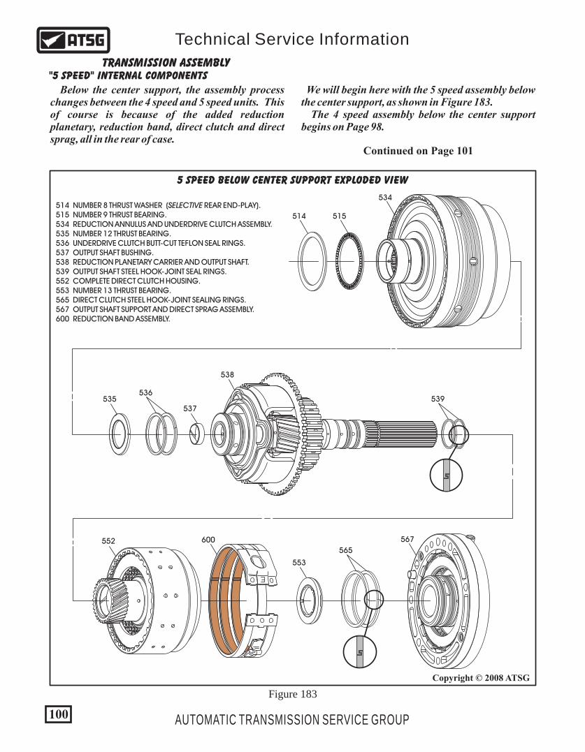
553
552
R
600 567
565
535537
538
536539
515
534
514
514 NUMBER 8 THRUST WASHER (SELECTIVE REAR END-PLAY). 515 NUMBER 9 THRUST BEARING. 534 REDUCTION ANNULUS AND UNDERDRIVE CLUTCH ASSEMBLY. 535 NUMBER 12 THRUST BEARING. 536 UNDERDRIVE CLUTCH BUTT-CUT TEFLON SEAL RINGS. 537 OUTPUT SHAFT BUSHING. 538 REDUCTION PLANETARY CARRIER AND OUTPUT SHAFT. 539 OUTPUT SHAFT STEEL HOOK-JOINT SEAL RINGS. 552 COMPLETE DIRECT CLUTCH HOUSING. 553 NUMBER 13 THRUST BEARING. 565 DIRECT CLUTCH STEEL HOOK-JOINT SEALING RINGS. 567 OUTPUT SHAFT SUPPORT AND DIRECT SPRAG ASSEMBLY. 600 REDUCTION BAND ASSEMBLY.
5 SPEED BELOW CENTER SUPPORT EXPLODED VIEW
"5 SPEED" INTERNAL COMPONENTSTRANSMISSION ASSEMBLY
Below the center support, the assembly process changes between the 4 speed and 5 speed units. This of course is because of the added reduction planetary, reduction band, direct clutch and direct sprag, all in the rear of case.
We will begin here with the 5 speed assembly below the center support, as shown in Figure 183. The 4 speed assembly below the center support begins on Page 98.
Continued on Page 101
Figure 183
100
Copyright © 2008 ATSG
AUTOMATIC TRANSMISSION SERVICE GROUP
Technical Service Information
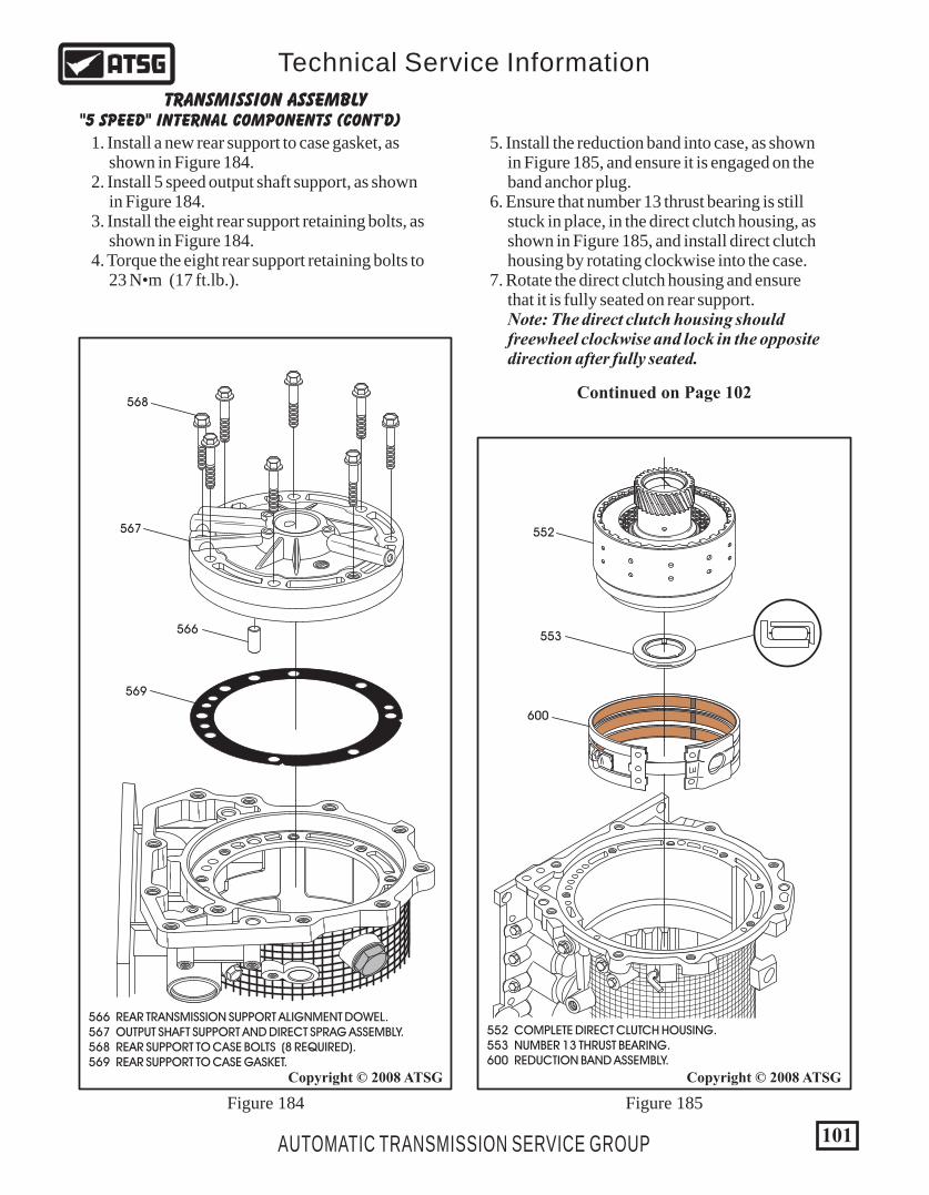
101AUTOMATIC TRANSMISSION SERVICE GROUP
Technical Service Information
"5 SPEED" INTERNAL COMPONENTS (CONT'D)TRANSMISSION ASSEMBLY
566 REAR TRANSMISSION SUPPORT ALIGNMENT DOWEL. 567 OUTPUT SHAFT SUPPORT AND DIRECT SPRAG ASSEMBLY. 568 REAR SUPPORT TO CASE BOLTS (8 REQUIRED). 569 REAR SUPPORT TO CASE GASKET.
568
566
567
569
Figure 184
Copyright © 2008 ATSG
R
Figure 185
Copyright © 2008 ATSG
552
600
553
552 COMPLETE DIRECT CLUTCH HOUSING. 553 NUMBER 13 THRUST BEARING. 600 REDUCTION BAND ASSEMBLY.
1. Install a new rear support to case gasket, as shown in Figure 184. 2. Install 5 speed output shaft support, as shown in Figure 184. 3. Install the eight rear support retaining bolts, as shown in Figure 184. 4. Torque the eight rear support retaining bolts to 23 N•m (17 ft.lb.).
5. Install the reduction band into case, as shown in Figure 185, and ensure it is engaged on the band anchor plug. 6. Ensure that number 13 thrust bearing is still stuck in place, in the direct clutch housing, as shown in Figure 185, and install direct clutch housing by rotating clockwise into the case. 7. Rotate the direct clutch housing and ensure that it is fully seated on rear support. Note: The direct clutch housing should freewheel clockwise and lock in the opposite direction after fully seated.
Continued on Page 102
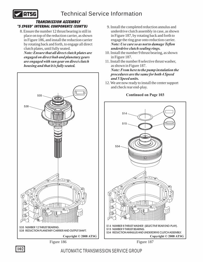
Continued on Page 103
"5 SPEED" INTERNAL COMPONENTS (CONT'D)TRANSMISSION ASSEMBLY
102 AUTOMATIC TRANSMISSION SERVICE GROUP
Technical Service Information
535
538
Copyright © 2008 ATSG
535 NUMBER 12 THRUST BEARING. 538 REDUCTION PLANETARY CARRIER AND OUTPUT SHAFT.
Figure 186
Copyright © 2008 ATSG
514 NUMBER 8 THRUST WASHER (SELECTIVE REAR END-PLAY). 515 NUMBER 9 THRUST BEARING. 534 REDUCTION ANNULUS AND UNDERDRIVE CLUTCH ASSEMBLY.
515
534
514
Figure 187
8. Ensure the number 12 thrust bearing is still in place on top of the reduction carrier, as shown in Figure 186, and install the reduction carrier by rotating back and forth, to engage all direct clutch plates, until fully seated. Note: Ensure that all direct clutch plates are engaged on direct hub and planetary gears are engaged with sun gear on direct clutch housing and that it is fully seated.
9. Install the completed reduction annulus and underdrive clutch assembly in case, as shown in Figure 187, by rotating back and forth to engage the ring gear onto reduction carrier. Note: Use care so as not to damage Teflon underdrive clutch sealing rings. 10. Install the number 9 thrust bearing, as shown in Figure 187. 11. Install the number 8 selective thrust washer, as shown in Figure 187. Note: From here to the pump instalation the procedures are the same for both 4 Speed and 5 Speed units. 12. We are now ready to install the center support and check rear end-play.
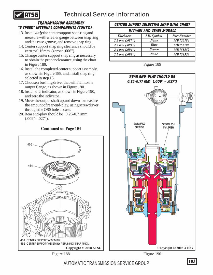
0
0
1010
5050
2020
4040
3030
103AUTOMATIC TRANSMISSION SERVICE GROUP
Technical Service Information
"5 SPEED" INTERNAL COMPONENTS (CONT'D)TRANSMISSION ASSEMBLY
Continued on Page 104
13. Install only the center support snap ring and measure with a feeler gauge between snap ring and the case groove, and remove snap ring. 14. Center support snap ring clearance should be zero to 0.16mm (zero to .006"). 15. Change center support snap ring as necessary to obtain the proper clearance, using the chart in Figure 189. 16. Install the completed center support assembly, as shown in Figure 188, and install snap ring selected in step 15. 17. Choose a bushing driver that will fit into the output flange, as shown in Figure 190. 18. Install dial indicator, as shown in Figure 190, and zero the indicator. 19. Move the output shaft up and down to measure the amount of rear end-play, using screwdriver through the OSS hole in case. 20. Rear end-play should be 0.25-0.71mm (.009" - .027").
Copyright © 2008 ATSG Copyright © 2008 ATSG
Figure 188
454 CENTER SUPPORT ASSEMBLY. 455 CENTER SUPPORT ASSEMBLY RETAINING SNAP RING.
454
455
Figure 190
Figure 189
REAR END-PLAY SHOULD BE0.25-0.71 MM (.009" - .027")
BUSHINGDRIVER
NUMBER 8WASHER
R/V4A51 AND V5A51 MODELS
CENTER SUPORT SELECTIVE SNAP RING CHART
2.2 mm (.087")
2.3 mm (.091")
2.4 mm (.094")
2.5 mm (.098")
Thickness
MD756784
MD756785
MD758552
MD758553
Part Number
None
Brown
None
Blue
I.D. Symbol
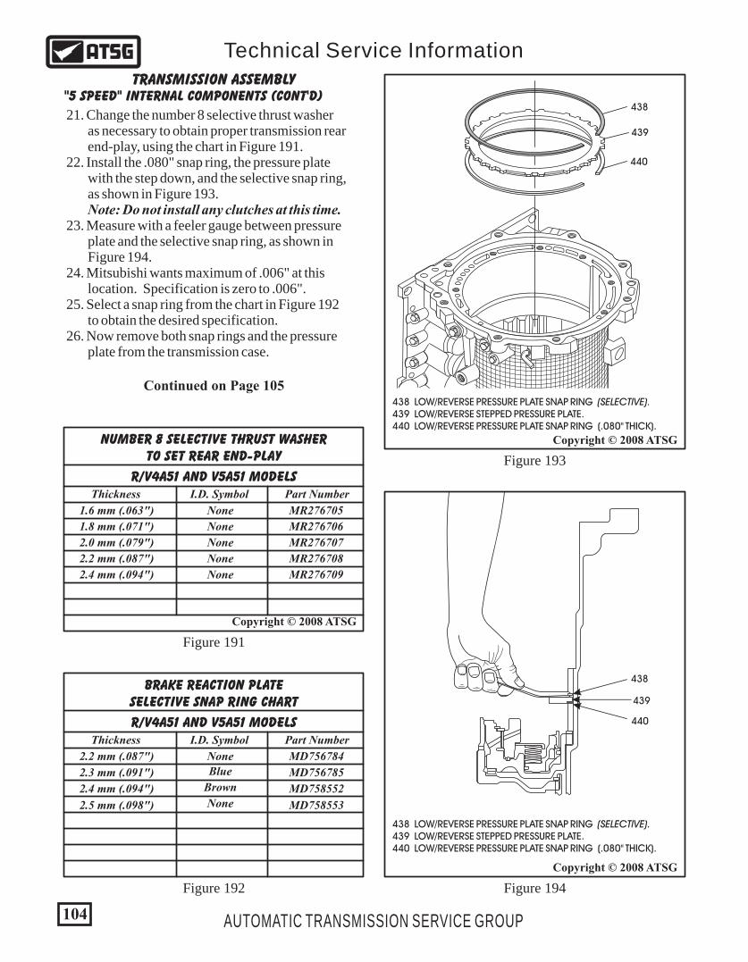
104
Copyright © 2008 ATSG
AUTOMATIC TRANSMISSION SERVICE GROUP
Technical Service Information
21. Change the number 8 selective thrust washer as necessary to obtain proper transmission rear end-play, using the chart in Figure 191. 22. Install the .080" snap ring, the pressure plate with the step down, and the selective snap ring, as shown in Figure 193. Note: Do not install any clutches at this time. 23. Measure with a feeler gauge between pressure plate and the selective snap ring, as shown in Figure 194. 24. Mitsubishi wants maximum of .006" at this location. Specification is zero to .006". 25. Select a snap ring from the chart in Figure 192 to obtain the desired specification. 26. Now remove both snap rings and the pressure plate from the transmission case.
R/V4A51 AND V5A51 MODELS
NUMBER 8 SELECTIVE THRUST WASHERTO SET REAR END-PLAY
1.6 mm (.063")
1.8 mm (.071")
2.0 mm (.079")
2.2 mm (.087")
2.4 mm (.094")
Thickness
MR276705
MR276706
MR276707
MR276708
MR276709
Part Number
None
None
None
None
None
I.D. Symbol
"5 SPEED" INTERNAL COMPONENTS (CONT'D)TRANSMISSION ASSEMBLY
Figure 191
Figure 192 Figure 194
Figure 193
438
438
439
439
440
440
Copyright © 2008 ATSG
Copyright © 2008 ATSG
438 LOW/REVERSE PRESSURE PLATE SNAP RING (SELECTIVE). 439 LOW/REVERSE STEPPED PRESSURE PLATE. 440 LOW/REVERSE PRESSURE PLATE SNAP RING (.080" THICK).
438 LOW/REVERSE PRESSURE PLATE SNAP RING (SELECTIVE). 439 LOW/REVERSE STEPPED PRESSURE PLATE. 440 LOW/REVERSE PRESSURE PLATE SNAP RING (.080" THICK).
Continued on Page 105
R/V4A51 AND V5A51 MODELS
BRAKE REACTION PLATESELECTIVE SNAP RING CHART
2.2 mm (.087")
2.3 mm (.091")
2.4 mm (.094")
2.5 mm (.098")
Thickness
MD756784
MD756785
MD758552
MD758553
Part Number
None
Brown
None
Blue
I.D. Symbol

105AUTOMATIC TRANSMISSION SERVICE GROUP
Technical Service Information
B
438
441
443
444
439
440
442
Copyright © 2008 ATSG
Figure 195
438 LOW/REVERSE PRESSURE PLATE SNAP RING (SELECTIVE). 439 LOW/REVERSE STEPPED PRESSURE PLATE. 440 LOW/REVERSE PRESSURE PLATE SNAP RING (.080" THICK). 441 LOW/REVERSE FRICTION PLATES (6 REQUIRED). 442 LOW/REVERSE STEEL PLATES (5 REQUIRED). 443 LOW/REVERSE "STEPPED" APPLY PLATE (SELECTIVE). 444 LOW/REVERSE "WAVED" CUSHION PLATE.
"5 SPEED" INTERNAL COMPONENTS (CONT'D)TRANSMISSION ASSEMBLY
Continued on Page 106
27. Install the low/reverse brake cushion plate, as shown in Figure 195. 28. Install low/reverse brake "stepped" selective apply plate, as shown in Figure 195, with the step facing down.
29. Install the low/reverse clutch plates beginning with a friction plate and alternating with steel plates, as shown in Figure 195. Note: "Do not" yet install the last friction. All clutch plates should be soaked in proper ATF for 30 minutes before assembly, and the number of plates may vary from illustration. 30. Install the .080" thick snap ring into the case groove, as shown in Figure 195. 31. Now install the last friction, the pressure plate with the step facing down and the selective snap ring that you chose in Step 23. Refer to Figure 195. 32. Measure the low/reverse clutch clearance using a feeler gauge carefully, between top friction and pressure plate, as shown in Figure 196. 33. The low/reverse clutch clearance should be 1.65 - 2.11 mm (.065" - .083"). 34. Change the selective apply plate as necessary to obtain specified clearance, using the chart in Figure 197.
Figure 196
Copyright © 2008 ATSG
Low/ReverseClutch Clearance
1.65-2.11 mm(.065 - .083")
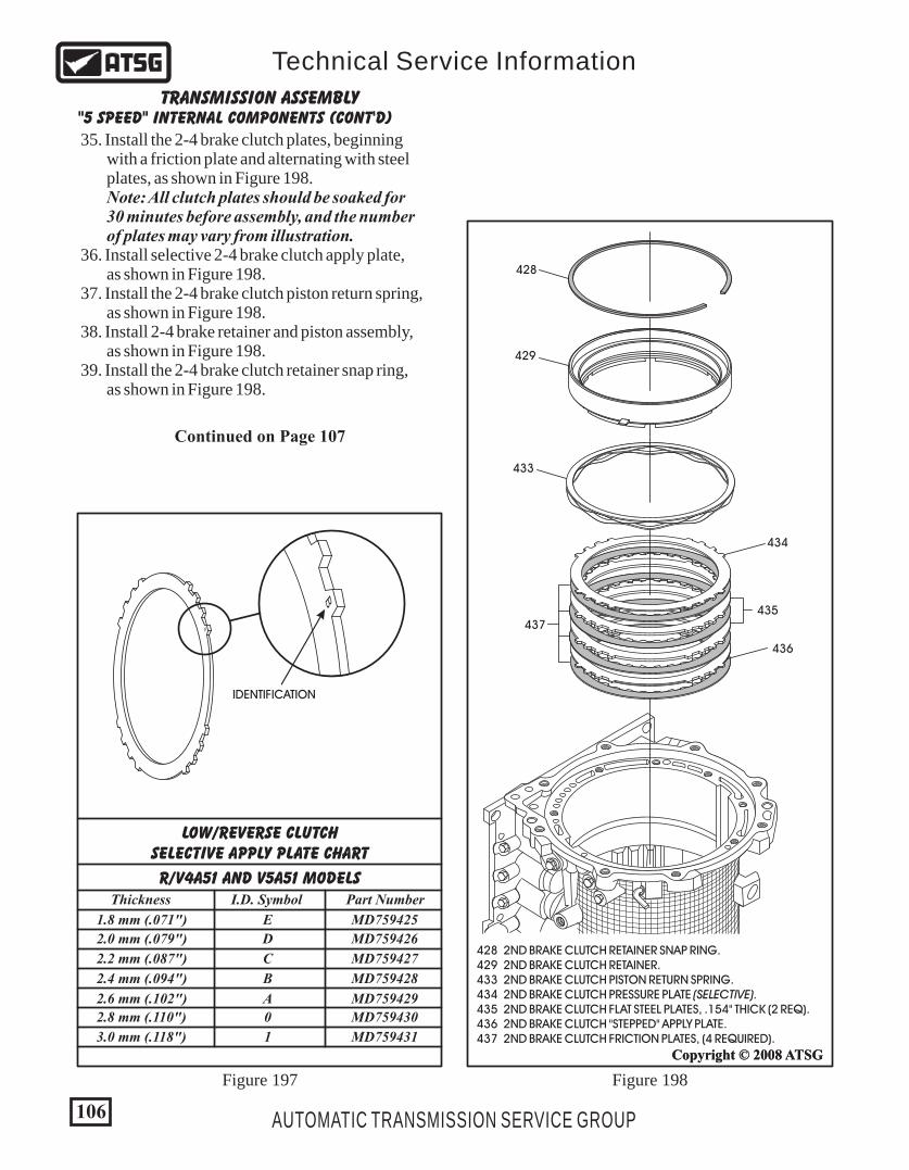
106 AUTOMATIC TRANSMISSION SERVICE GROUP
Technical Service Information
"5 SPEED" INTERNAL COMPONENTS (CONT'D)TRANSMISSION ASSEMBLY
Continued on Page 107
LOW/REVERSE CLUTCHSELECTIVE APPLY PLATE CHART
R/V4A51 AND V5A51 MODELSThickness Part NumberI.D. Symbol
B
B
IDENTIFICATION
1.8 mm (.071")
2.0 mm (.079")
2.2 mm (.087")
2.4 mm (.094")
2.6 mm (.102")
2.8 mm (.110")
3.0 mm (.118")
MD759425
MD759426
MD759427
MD759428
MD759429
MD759430
MD759431
E
D
C
B
A
0
1
Figure 197
35. Install the 2-4 brake clutch plates, beginning with a friction plate and alternating with steel plates, as shown in Figure 198. Note: All clutch plates should be soaked for 30 minutes before assembly, and the number of plates may vary from illustration. 36. Install selective 2-4 brake clutch apply plate, as shown in Figure 198. 37. Install the 2-4 brake clutch piston return spring, as shown in Figure 198. 38. Install 2-4 brake retainer and piston assembly, as shown in Figure 198. 39. Install the 2-4 brake clutch retainer snap ring, as shown in Figure 198.
Copyright © 2008 ATSG
428
429
433
434
436
435437
C
Copyright © 2008 ATSG
428 2ND BRAKE CLUTCH RETAINER SNAP RING. 429 2ND BRAKE CLUTCH RETAINER. 433 2ND BRAKE CLUTCH PISTON RETURN SPRING. 434 2ND BRAKE CLUTCH PRESSURE PLATE (SELECTIVE). 435 2ND BRAKE CLUTCH FLAT STEEL PLATES, .154" THICK (2 REQ). 436 2ND BRAKE CLUTCH "STEPPED" APPLY PLATE. 437 2ND BRAKE CLUTCH FRICTION PLATES, (4 REQUIRED).
Figure 198

107AUTOMATIC TRANSMISSION SERVICE GROUP
Technical Service Information
509
510
Copyright © 2008 ATSG
Figure 201
509 THRUST BEARING NUMBER 7. 510 PLANETARY GEAR TRAIN AND LOW SPRAG ASSEMBLY.
2ND BRAKE CLUTCHSELECTIVE APPLY PLATE CHART
R/V4A51 AND V5A51 MODELS
1.8 mm (.071")
2.0 mm (.079")
2.2 mm (.087")
2.4 mm (.094")
2.6 mm (.102")
2.8 mm (.110")
3.0 mm (.118")
1.6 mm (.063")
Thickness
MR336391
MR336392
MR336393
MR336394
MR336395
MR336396
MR336397
MR336390
Part Number
F
E
D
C
B
A
0
1
I.D. Symbol
B
B
IDENTIFICATION
Figure 200
Copyright © 2008 ATSG
2-4 BrakeClutch Clearance
1.49-1.95 mm(.058 - .077")
Figure 199
"5 SPEED" INTERNAL COMPONENTS (CONT'D)TRANSMISSION ASSEMBLY
40. Measure the 2-4 brake clutch clearance with a feeler gauge, between the apply plate and the 2-4 clutch piston, as shown in Figure 200. 41. The 2-4 brake clutch clearance should be 1.49 - 1.95 mm (.058" - .077"). 42. Change the selective apply plate as necessary, using the chart in Figure 199, to obtain proper 2-4 brake clutch clearance. 43. Now, remove the complete 2-4 brake clutch pack, using Figure 198 as a guide. 44. Install the completed planetary gear set and low sprag assembly, by rotating in a clockwise direction to engage the low/reverse frictions and ensuring the number 7 thrust bearing is still in place, as shown in Figure 201. Note: Planetary gear set should freewheel clockwise and lock counter-clockwise.
Continued on Page 108
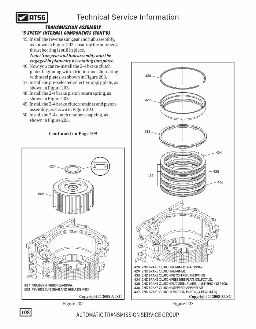
Copyright © 2008 ATSG
428
429
433
434
436
435437
C
428 2ND BRAKE CLUTCH RETAINER SNAP RING. 429 2ND BRAKE CLUTCH RETAINER. 433 2ND BRAKE CLUTCH PISTON RETURN SPRING. 434 2ND BRAKE CLUTCH PRESSURE PLATE (SELECTIVE). 435 2ND BRAKE CLUTCH FLAT STEEL PLATES, .154" THICK (2 REQ). 436 2ND BRAKE CLUTCH "STEPPED" APPLY PLATE. 437 2ND BRAKE CLUTCH FRICTION PLATES, (4 REQUIRED).
Figure 203
108 AUTOMATIC TRANSMISSION SERVICE GROUP
Technical Service Information
427
502
Copyright © 2008 ATSG
Figure 202
427 NUMBER 4 THRUST BEARING. 502 REVERSE SUN GEAR AND HUB ASSEMBLY.
TRANSMISSION ASSEMBLY"5 SPEED" INTERNAL COMPONENTS (CONT'D)
45. Install the reverse sun gear and hub assembly, as shown in Figure 202, ensuring the number 4 thrust bearing is still in place. Note: Sun gear and hub assembly must be engaged in planetary by rotating into place. 46. Now you can re-install the 2-4 brake clutch plates beginning with a friction and alternating with steel plates, as shown in Figure 203. 47. Install the pre-selected selective apply plate, as shown in Figure 203. 48. Install the 2-4 brake piston return spring, as shown in Figure 203. 49. Install the 2-4 brake clutch retainer and piston assembly, as shown in Figure 203. 50. Install the 2-4 clutch retainer snap ring, as shown in Figure 203.
Continued on Page 109
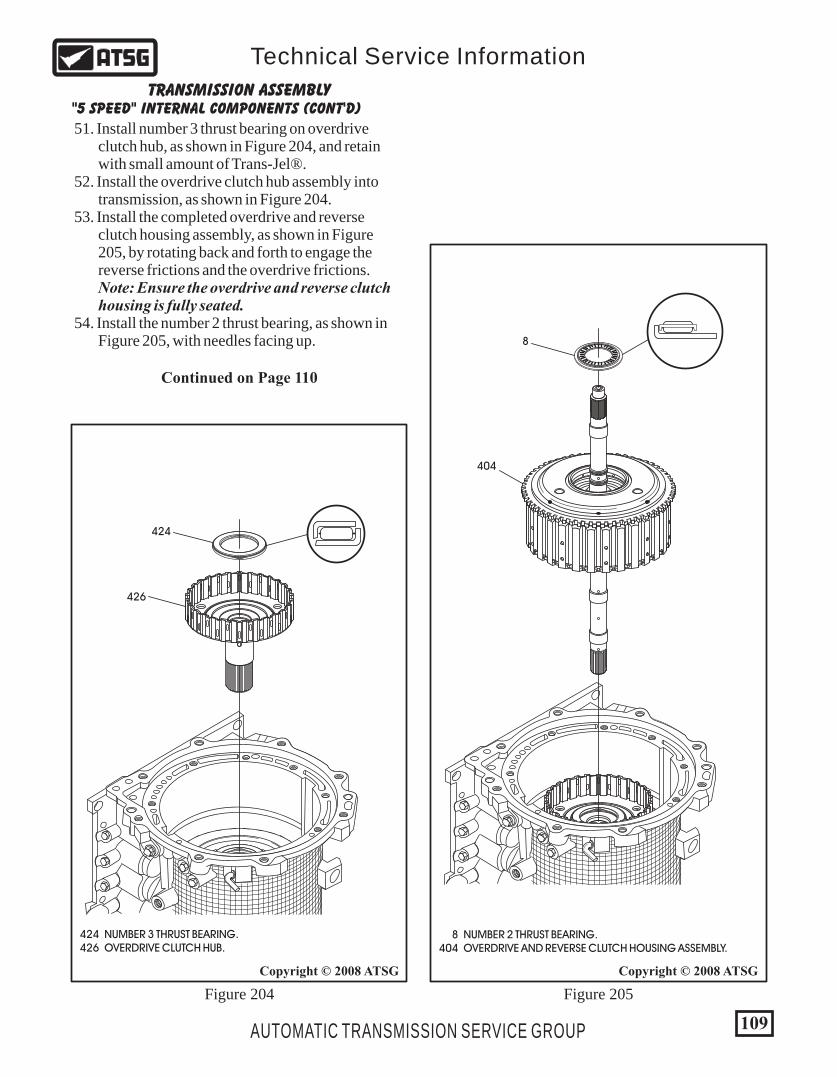
109AUTOMATIC TRANSMISSION SERVICE GROUP
Technical Service Information
424
426
Copyright © 2008 ATSG
Figure 204
424 NUMBER 3 THRUST BEARING. 426 OVERDRIVE CLUTCH HUB.
TRANSMISSION ASSEMBLY"5 SPEED" INTERNAL COMPONENTS (CONT'D)
51. Install number 3 thrust bearing on overdrive clutch hub, as shown in Figure 204, and retain with small amount of Trans-Jel®. 52. Install the overdrive clutch hub assembly into transmission, as shown in Figure 204. 53. Install the completed overdrive and reverse clutch housing assembly, as shown in Figure 205, by rotating back and forth to engage the reverse frictions and the overdrive frictions. Note: Ensure the overdrive and reverse clutch housing is fully seated. 54. Install the number 2 thrust bearing, as shown in Figure 205, with needles facing up.
Continued on Page 110
8 NUMBER 2 THRUST BEARING. 404 OVERDRIVE AND REVERSE CLUTCH HOUSING ASSEMBLY.
404
Copyright © 2008 ATSG
Figure 205
8
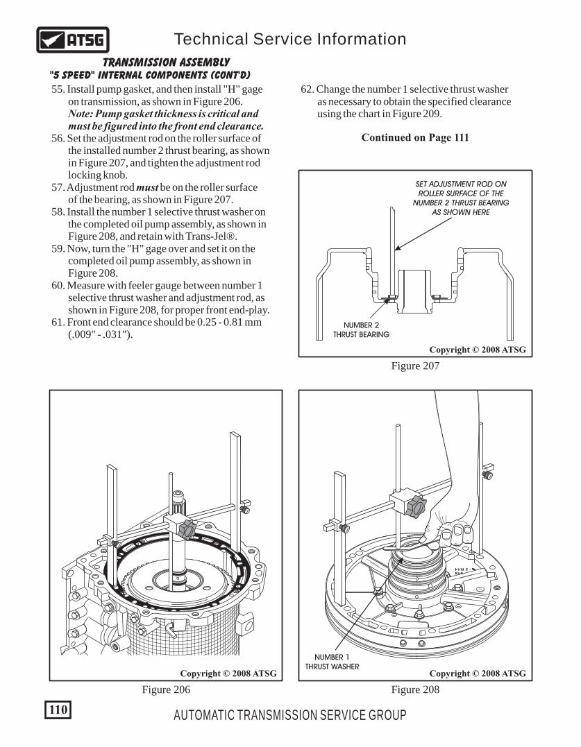
- 3 R14918
D 3
1 3
110
Copyright © 2008 ATSG
Copyright © 2008 ATSG
Copyright © 2008 ATSG
AUTOMATIC TRANSMISSION SERVICE GROUP
Technical Service Information
SET ADJUSTMENT ROD ONROLLER SURFACE OF THE
NUMBER 2 THRUST BEARINGAS SHOWN HERE
NUMBER 2THRUST BEARING
NUMBER 1THRUST WASHER
Figure 207
Figure 206 Figure 208
TRANSMISSION ASSEMBLY"5 SPEED" INTERNAL COMPONENTS (CONT'D)
55. Install pump gasket, and then install "H" gage on transmission, as shown in Figure 206. Note: Pump gasket thickness is critical and must be figured into the front end clearance. 56. Set the adjustment rod on the roller surface of the installed number 2 thrust bearing, as shown in Figure 207, and tighten the adjustment rod locking knob. 57. Adjustment rod must be on the roller surface of the bearing, as shown in Figure 207. 58. Install the number 1 selective thrust washer on the completed oil pump assembly, as shown in Figure 208, and retain with Trans-Jel®. 59. Now, turn the "H" gage over and set it on the completed oil pump assembly, as shown in Figure 208. 60. Measure with feeler gauge between number 1 selective thrust washer and adjustment rod, as shown in Figure 208, for proper front end-play. 61. Front end clearance should be 0.25 - 0.81 mm (.009" - .031").
Continued on Page 111
62. Change the number 1 selective thrust washer as necessary to obtain the specified clearance using the chart in Figure 209.
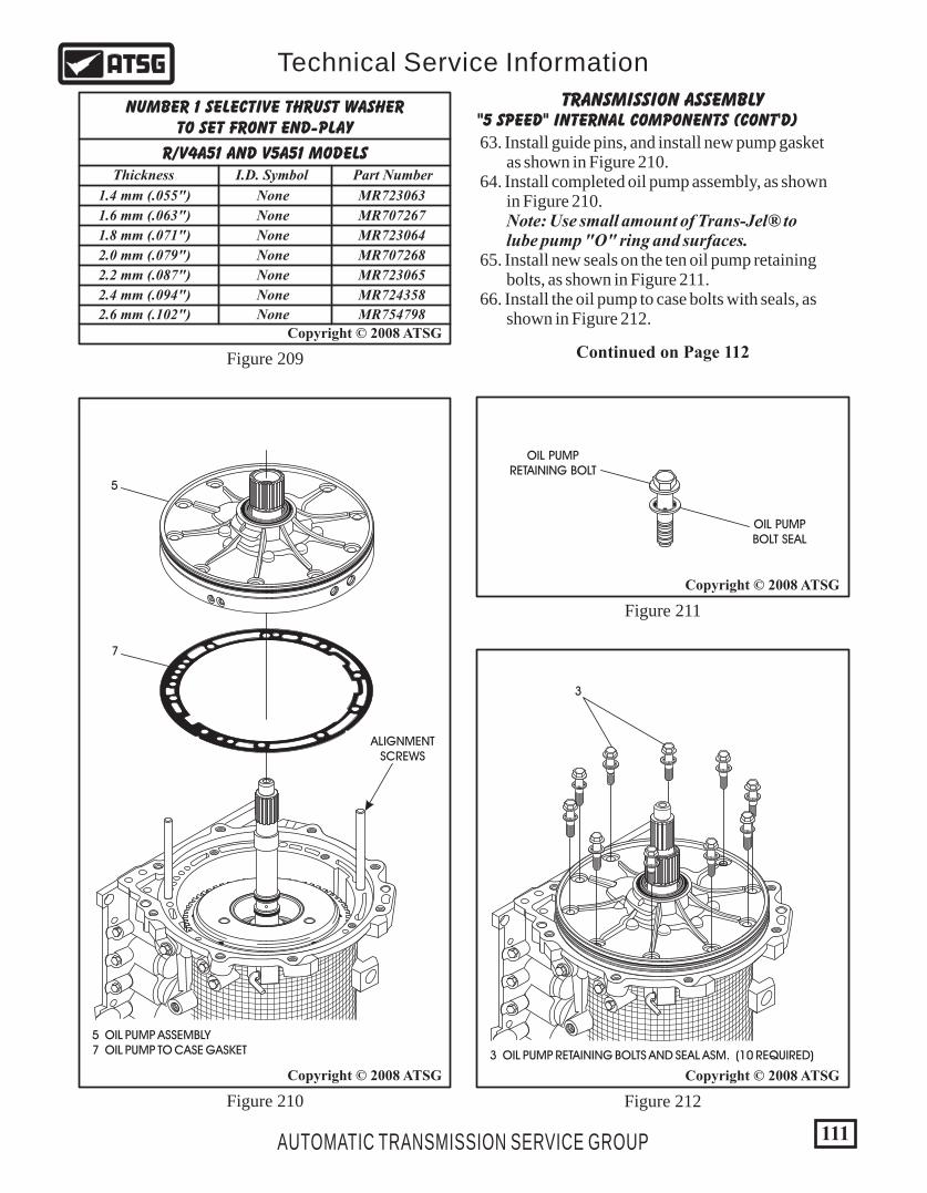
111
Copyright © 2008 ATSG
AUTOMATIC TRANSMISSION SERVICE GROUP
Technical Service Information
R/V4A51 AND V5A51 MODELS
NUMBER 1 SELECTIVE THRUST WASHERTO SET FRONT END-PLAY
1.6 mm (.063")
1.4 mm (.055")
1.8 mm (.071")
2.0 mm (.079")
2.2 mm (.087")
2.4 mm (.094")
2.6 mm (.102")
Thickness
MR707267
MR723063
MR723064
MR707268
MR723065
MR724358
MR754798
Part Number
None
None
None
None
None
None
None
I.D. Symbol
Figure 209
63. Install guide pins, and install new pump gasket as shown in Figure 210. 64. Install completed oil pump assembly, as shown in Figure 210. Note: Use small amount of Trans-Jel® to lube pump "O" ring and surfaces. 65. Install new seals on the ten oil pump retaining bolts, as shown in Figure 211. 66. Install the oil pump to case bolts with seals, as shown in Figure 212.
TRANSMISSION ASSEMBLY"5 SPEED" INTERNAL COMPONENTS (CONT'D)
Continued on Page 112
Copyright © 2008 ATSG
5 OIL PUMP ASSEMBLY 7 OIL PUMP TO CASE GASKET
5
7
ALIGNMENTSCREWS
Figure 210
Copyright © 2008 ATSG
OIL PUMPRETAINING BOLT
OIL PUMPBOLT SEAL
Figure 211
Copyright © 2008 ATSG
3
3 OIL PUMP RETAINING BOLTS AND SEAL ASM. (10 REQUIRED)
Figure 212

1010
V5A51 7AB
BL7430
40 REDUCTION BAND SERVO COVER SNAP RING. 41 REDUCTION BAND SERVO COVER AND "O" RING ASSEMBLY.
1010
"5 SPEED" INTERNAL COMPONENTS (CONT'D)TRANSMISSION ASSEMBLY
Continued on Page 113
112 AUTOMATIC TRANSMISSION SERVICE GROUP
Technical Service Information
Copyright © 2008 ATSG
Copyright © 2008 ATSG
1010
V5A51 7AB
BL7430
43
44
46
43 REDUCTION BAND SERVO PISTON RETAINING SNAP RING. 44 REDUCTION BAND SERVO APPLY PISTON ASSEMBLY. 46 REDUCTION BAND SERVO PISTON RETURN SPRING.
Figure 214
Figure 213
67. Torque the ten oil pump assembly to case bolts to 23 N•m (17 ft.lb.), as shown in Figure 213. Note: Install dial indicator on turbine shaft and verify front end-play is correct. 68. Install the reduction servo return spring into case, as shown in Figure 214. 69. Install pre-assembled reduction servo piston and seal assembly, as shown in Figure 214, compress the spring and install snap ring, with flat side facing down. Note: Place the cavity in the piston and the opening in the snap ring, to opening in case as shown in Figure 214. 70. Turn the adjusting screw in completely with a substantial amount of torque to ensure band is fully seated on anchor plug and servo pin. 71. Torque the adjustment screw to 44 in.lb. and back off 5-1/2 to 5-3/4 turns, and torque the lock nut to 18 N•m (13 ft.lb.). Note: Mitsubishi supplies a special tool to hold the piston from turning during the adjustment process, as shown in Figure 214. A screwdriver, bent just right and cut off, will serve the same purpose. 72. Install the pre-assembled reduction servo cover and snap ring, flat side facing down, as shown in Figure 215.
TORQUE OIL PUMP TO CASE BOLTS TO23 N•M (17 FT.LB.) AND RE-CHECKEND-PLAY WITH DIAL INDICATOR
40
41
INSTALLS INTO PISTONCAVITY, AS SHOWN
OPENING IN SNAP RINGTO OPENING IN CASE
PISTON HOLDINGTOOL MB991693
Copyright © 2008 ATSG
Figure 215

113
Copyright © 2008 ATSG
Copyright © 2008 ATSG
AUTOMATIC TRANSMISSION SERVICE GROUP
Technical Service Information
"5 SPEED" INTERNAL COMPONENTS (CONT'D)TRANSMISSION ASSEMBLY
73. Install the complete wiring harness through the inside of the case, as shown in Figure 217. 74. Install the external snap ring into groove of the pass-thru connector, as shown in Figure 216. 75. Install new low/reverse seal and new 2nd brake seal into transmission case cavities, as shown in Figure 217. Note: Install both seals so that the notched section is parallel with the centerline of the transmission, as shown in Figure 217. 76. Install oil screen into case cavity, as shown in Figure 217.
6 00
6 00
1010
V5A51 7AB
BL7430
WIREHARNESSASSEMBLY
"O" RINGSEAL
SNAPRING
SNAPRING
LOW/REVERSECLUTCH SEAL
OILSCREEN
2ND BRAKECLUTCH SEAL
Figure 216
Figure 217
Continued on Page 115
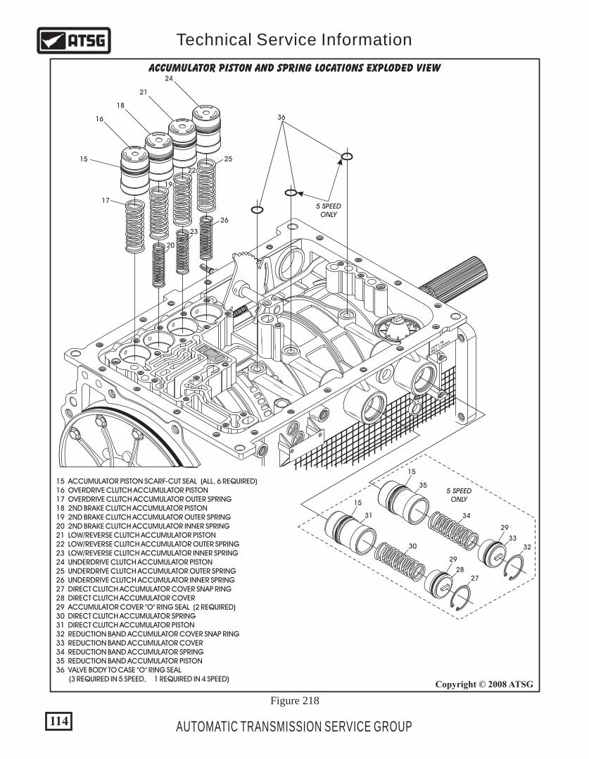
114
Copyright © 2008 ATSG
AUTOMATIC TRANSMISSION SERVICE GROUP
Technical Service Information
6 00
6 00
1010
V5A51 7AB
BL7430
16
15
19
22
20
23
25
26
27
32
33
34
5 SPEEDONLY
35
36
5 SPEEDONLY
28
29
29
30
31
15
15
17
18
21
24
15 ACCUMULATOR PISTON SCARF-CUT SEAL (ALL, 6 REQUIRED) 16 OVERDRIVE CLUTCH ACCUMULATOR PISTON 17 OVERDRIVE CLUTCH ACCUMULATOR OUTER SPRING 18 2ND BRAKE CLUTCH ACCUMULATOR PISTON 19 2ND BRAKE CLUTCH ACCUMULATOR OUTER SPRING 20 2ND BRAKE CLUTCH ACCUMULATOR INNER SPRING 21 LOW/REVERSE CLUTCH ACCUMULATOR PISTON 22 LOW/REVERSE CLUTCH ACCUMULATOR OUTER SPRING 23 LOW/REVERSE CLUTCH ACCUMULATOR INNER SPRING 24 UNDERDRIVE CLUTCH ACCUMULATOR PISTON 25 UNDERDRIVE CLUTCH ACCUMULATOR OUTER SPRING 26 UNDERDRIVE CLUTCH ACCUMULATOR INNER SPRING 27 DIRECT CLUTCH ACCUMULATOR COVER SNAP RING 28 DIRECT CLUTCH ACCUMULATOR COVER 29 ACCUMULATOR COVER "O" RING SEAL (2 REQUIRED) 30 DIRECT CLUTCH ACCUMULATOR SPRING 31 DIRECT CLUTCH ACCUMULATOR PISTON 32 REDUCTION BAND ACCUMULATOR COVER SNAP RING 33 REDUCTION BAND ACCUMULATOR COVER 34 REDUCTION BAND ACCUMULATOR SPRING 35 REDUCTION BAND ACCUMULATOR PISTON 36 VALVE BODY TO CASE "O" RING SEAL (3 REQUIRED IN 5 SPEED, 1 REQUIRED IN 4 SPEED)
ACCUMULATOR PISTON AND SPRING LOCATIONS EXPLODED VIEW
Figure 218

77. Install the accumulator springs and pistons with new seals, as shown in Figure 218. Note: Use the chart in Figure 219 to ID the springs, if you forgot to tag them. 78. Install the direct clutch and reduction band accumulator pistons with new seals and the springs, as shown in Figure 218. 79. Install new seals on the covers and install them into case, and install snap rings, as shown in Figure 218. Note: These two accumulators are not used in the 4 speed transmissions. 80. Remove the two long hollow alignment dowels from the valve body and install them into the case in the positions shown in Figure 220. 81. Install the valve body to case "O" ring seals in case cavities, as shown in Figure 220, retain with small amount of Trans-Jel®. Note: Only one used in 4 speed units.
115AUTOMATIC TRANSMISSION SERVICE GROUP
Technical Service Information
"5 SPEED" INTERNAL COMPONENTS (CONT'D)TRANSMISSION ASSEMBLY ACCUMULATOR SPRING
IDENTIFICATION
Continued on Page 116
6 00
6 00
1010
V5A51 7AB
BL7430
368
368
36
36
36
5 SPEEDONLY
36 VALVE BODY TO CASE "O" RING SEALS. (3 REQUIRED IN 5 SPEED, 1 REQUIRED IN 4 SPEED) 368 VALVE BODY TO CASE HOLLOW ALIGNMENT DOWELS.
Copyright © 2008 ATSG
Figure 220
18
NO. ACCUMULATOR
Low/Reverse Clutch
Underdrive Clutch
Direct Clutch
Reduction Band
2nd Brake Clutch
Overdrive Clutch None Not Used
Not Used
Not Used
Full Surface 2/3rds
2/3rds Full Surface
Half or 2/3rds Half or 2/3rds
None
None
I.D. "Bluing"Outer
I.D. "Bluing"Inner
16
18
21
24
31
35
242116
OR
NOTE: The shaded areas are theidentification "Bluing".
Figure 219
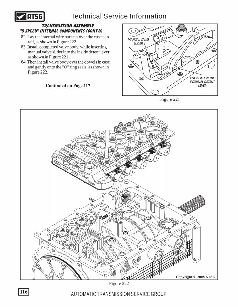
6 00
6 00
1010
V5A51 7AB
BL7430
180X
6
00
- 2777
Figure 222
116
Copyright © 2008 ATSG
AUTOMATIC TRANSMISSION SERVICE GROUP
Technical Service Information
82. Lay the internal wire harness over the case pan rail, as shown in Figure 222. 83. Install completed valve body, while inserting manual valve slider into the inside detent lever, as shown in Figure 221. 84. Then install valve body over the dowels in case and gently onto the "O" ring seals, as shown in Figure 222.
"5 SPEED" INTERNAL COMPONENTS (CONT'D)TRANSMISSION ASSEMBLY
Continued on Page 117
MANUAL VALVESLIDER
ENGAGED IN THEINTERNAL DETENT
LEVER
Figure 221
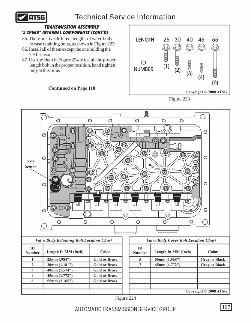
006
0X18
- 2
1
2
2 2
3
3
3
4
4
4
4
4
4
47
7
55
5
5
5 5 5 5
55
5
5
5
5
5
4
6
4
4
3
3
- 2777
85. There are five different lengths of valve body to case retaining bolts, as shown in Figure 223. 86. Install all of them except the one holding the TFT sensor. 87. Use the chart in Figure 224 to install the proper length bolt in the proper position, hand tighten only at this time.
"5 SPEED" INTERNAL COMPONENTS (CONT'D)TRANSMISSION ASSEMBLY
Continued on Page 118
117AUTOMATIC TRANSMISSION SERVICE GROUP
Technical Service Information
Copyright © 2008 ATSG
Copyright © 2008 ATSG
IDNumber
1 Gold or Brass25mm (.984")
2 Gold or Brass30mm (1.181")
3 Gold or Brass40mm (1.574")
4 Gold or Brass45mm (1.772")
6 Gold or Brass55mm (2.165")
Length In MM (Inch) Color
Valve Body Retaining Bolt Location Chart
IDNumber
5 Gray or Black50mm (1.968")
7 Gray or Black45mm (1.772")
Length In MM (Inch) Color
Valve Body Cover Bolt Location Chart
30
(2)
25
(1)
LENGTH
IDNUMBER
40
(3)
45
(4)
55
(6)
Figure 223
Figure 224
TFTSensor

6 00
6 00
1010
V5A51 7AB
BL7430
180X
6
00
- 2777
"5 SPEED" INTERNAL COMPONENTS (CONT'D)TRANSMISSION ASSEMBLY
88. Install new "O" ring seal onto the TFT sensor, as shown in Figure 225. 89. Install the completed TFT sensor into the valve body, as shown in Figure 225, and hand tighten only at this time. Note: Some models the retaining bolt screws into the valve body, and other models the bolt goes through the valve body and screws into the case. 90. Now, you can torque all valve body to case retaining bolts to 11 N•m (97 in.lb.), as shown in Figure 225. 91. Install the inside detent detent spring and bolt, as shown in Figure 225, and torque the bolt to 6 N•m (52 in.lb.).
Continued on Page 119
118 AUTOMATIC TRANSMISSION SERVICE GROUP
Technical Service Information
Copyright © 2008 ATSG
Copyright © 2008 ATSG
TFTSENSOR
DETENTSPRING
DISCONNECTEDWIRE HARNESS
RETAININGBOLT
25MM LENGTH
RETAININGBOLT
10MM LENGTH
"O" RINGSEAL
Figure 225
Beginning in mid-year 2000 Mitsubishi introduced an expanded capacity transmission oil pan that is deeper and requires a oil filter with a longer pick up tube, and a longer dipstick. This package was introduced to help eliminate an overheat condition and is available under OEM part number MR593383.
>PA
66 - G
F 30
<
NO
K
MR
52
88
36
>PA
66 - G
F 30
<
NO
K EarlyOil Filter
LateOil Filter
Figure 226
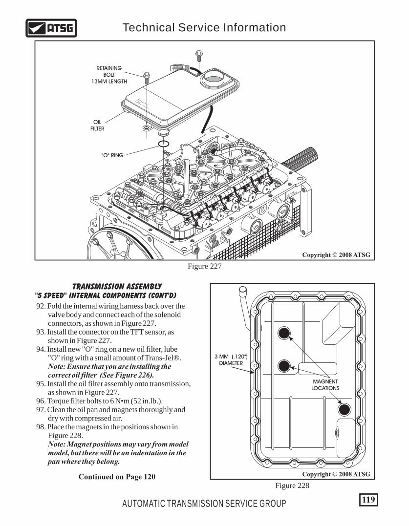
119AUTOMATIC TRANSMISSION SERVICE GROUP
Technical Service Information
"5 SPEED" INTERNAL COMPONENTS (CONT'D)TRANSMISSION ASSEMBLY
92. Fold the internal wiring harness back over the valve body and connect each of the solenoid connectors, as shown in Figure 227. 93. Install the connector on the TFT sensor, as shown in Figure 227. 94. Install new "O" ring on a new oil filter, lube "O" ring with a small amount of Trans-Jel®. Note: Ensure that you are installing the correct oil filter (See Figure 226). 95. Install the oil filter assembly onto transmission, as shown in Figure 227. 96. Torque filter bolts to 6 N•m (52 in.lb.). 97. Clean the oil pan and magnets thoroughly and dry with compressed air. 98. Place the magnets in the positions shown in Figure 228. Note: Magnet positions may vary from model model, but there will be an indentation in the pan where they belong.
Copyright © 2008 ATSG
Figure 227
RETAININGBOLT
13MM LENGTH
OILFILTER
"O" RING
6 00
6 00
1010
V5A51 7AB
BL7430
180X
6
00
- 2777
>PA
66 - G
F 30
<
NO
K
MR
52
88
36
Continued on Page 120Figure 228
3 MM (.120")DIAMETER
MAGNENTLOCATIONS
Copyright © 2008 ATSG
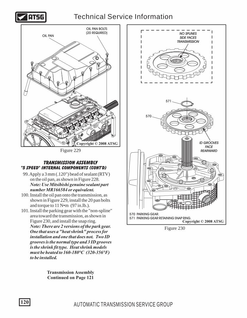
6 00
6 00
1010
V5A51 7AB
BL7430
180X
6
00
- 2777
>PA
66 - G
F 30
<
NO
K
MR
52
88
36
Copyright © 2008 ATSG
120 AUTOMATIC TRANSMISSION SERVICE GROUP
Technical Service Information
Figure 229
"5 SPEED" INTERNAL COMPONENTS (CONT'D)
99. Apply a 3 mm (.120") bead of sealant (RTV) on the oil pan, as shown in Figure 228. Note: Use Mitsibishi genuine sealant part number MR166584 or equivalent.100. Install the oil pan onto the transmission, as shown in Figure 229, install the 20 pan bolts and torque to 11 N•m (97 in.lb.).101. Install the parking gear with the "non-spline" area toward the transmission, as shown in Figure 230, and install the snap ring. Note: There are 2 versions of the park gear. One that uses a "heat shrink" process for installation and one that does not. Two ID grooves is the normal type and 3 ID grooves is the shrink fit type. Heat shrink models must be heated to 160-180°C (320-356°F) to be installed.
OIL PAN
OIL PAN BOLTS(20 REQUIRED)
570
571
ID GROOVESFACE
REARWARD
570 PARKING GEAR. 571 PARKING GEAR RETAINING SNAP RING.
Figure 230
Copyright © 2008 ATSG
NO SPLINESSIDE FACES
TRANSMISSION
TRANSMISSION ASSEMBLY
Transmission AssemblyContinued on Page 121
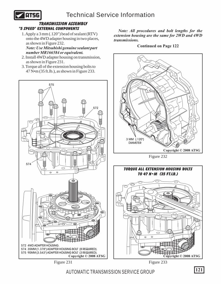
121AUTOMATIC TRANSMISSION SERVICE GROUP
Technical Service Information
"5 SPEED" EXTERNAL COMPONENTSTRANSMISSION ASSEMBLY
Continued on Page 122
572
575
574
572 4WD ADAPTER HOUSING. 574 35MM (1.378") ADAPTER HOUSING BOLT (8 REQUIRED). 575 90MM (3.543") ADAPTER HOUSING BOLT (3 REQUIRED).
Figure 231
Copyright © 2008 ATSG Copyright © 2008 ATSG
1. Apply a 3 mm (.120") bead of sealant (RTV) onto the 4WD adapter housing in two places, as shown in Figure 232. Note: Use Mitsubishi genuine sealant part number MR166584 or equivalent. 2. Install 4WD adapter housing on transmission, as shown in Figure 231. 3. Torque all of the extension housing bolts to 47 N•m (35 ft.lb.), as shown in Figure 233.
Figure 232
Figure 233
Copyright © 2008 ATSG
3 MM (.120")DIAMETER
TORQUE ALL EXTENSION HOUSING BOLTSTO 47 N•M (35 FT.LB.)
Note: All procedures and bolt lengths for the extension housing are the same for 2WD and 4WD transmissions.

Copyright © 2008 ATSG Copyright © 2008 ATSG
12
1 CONVERTER HOUSING 2 CONVERTER HOUSING RETAINING BOLTS (8 REQUIRED)
Figure 234 Figure 236
Figure 235
122 AUTOMATIC TRANSMISSION SERVICE GROUP
Technical Service Information
TRANSMISSION ASSEMBLY"5 SPEED" EXTERNAL PARTS (CONT'D)
4. Lubricate the oil pump "O" ring and the inside surface of the converter housing with a small amount of Trans-Jel®. 5. Apply a 2 mm (.080") bead of sealant (RTV) to the case side of the converter housing, as shown in Figure 235. Note: Use Mitsubishi genuine sealant part number MR166584 or equivalent. 6. Install the converter housing onto transmission case, as shown in Figure 234, and install the eight retaining bolts.
Copyright © 2008 ATSG
2 MM (.080")DIAMETER
7. Torque the eight converter housing retaining bolts to 47 N•m (35 ft.lb.), as shown in Figure 236.
Continued on Page 123
TORQUE CONVERTER HOUSING BOLTSTO 47 N·M (35 FT.LB.)
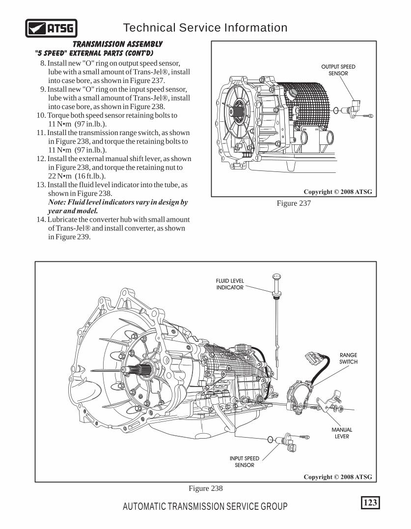
123
Copyright © 2008 ATSG
AUTOMATIC TRANSMISSION SERVICE GROUP
Technical Service Information
TRANSMISSION ASSEMBLY"5 SPEED" EXTERNAL PARTS (CONT'D)
8. Install new "O" ring on output speed sensor, lube with a small amount of Trans-Jel®, install into case bore, as shown in Figure 237. 9. Install new "O" ring on the input speed sensor, lube with a small amount of Trans-Jel®, install into case bore, as shown in Figure 238. 10. Torque both speed sensor retaining bolts to 11 N•m (97 in.lb.). 11. Install the transmission range switch, as shown in Figure 238, and torque the retaining bolts to 11 N•m (97 in.lb.). 12. Install the external manual shift lever, as shown in Figure 238, and torque the retaining nut to 22 N•m (16 ft.lb.). 13. Install the fluid level indicator into the tube, as shown in Figure 238. Note: Fluid level indicators vary in design by year and model. 14. Lubricate the converter hub with small amount of Trans-Jel® and install converter, as shown in Figure 239.
B 2
FLUID LEVELINDICATOR
INPUT SPEEDSENSOR
RANGESWITCH
MANUALLEVER
HO
TA
DJU
ST A
T H
OT
A T F
Figure 238
Copyright © 2008 ATSG
OUTPUT SPEEDSENSOR
RB DC
Figure 237

B 2
TORQUECONVERTER
Copyright © 2008 ATSG
Copyright © 2008 ATSG
Figure 239
Figure 240
124 AUTOMATIC TRANSMISSION SERVICE GROUP
Technical Service Information
TORQUE SPECIFICATIONS
CONGRATULATIONSYOU ARE FINISHED!
Component
Output Shaft Support to Case
Oil Pump Assembly to Case
Oil Pump Cover to Pump Body
Reduction Band Adjustment Locking Nut
Reduction Band Anchor
Valve Body to Case
Valve Body Cover to Valve Body
Valve Body to Solenoid Body
Solenoid Bracket to Solenoid Body
Spacer Plate to Valve Body
Oil Filter to Valve Body
Detent Spring to Valve Body
Oil Pan to Case
4WD Adapter Housing/Extension Housing to Case
Speedometer Adapter to 2WD Extension Housing
Converter Housing to Case
Output Speed Sensor to Case
Input Speed Sensor to Case
Transmission Range Sensor to Case
External Manual Shift Lever Nut
Oil Pressure Test Plugs
N•m
23
23
11
18
98
11
11
11
7
7
6
6
11
47
18
47
11
11
11
22
11
Ft.Lb.
17
17
13
72
35
13
35
97
In.Lb.
97
97
97
97
62
62
52
52
97
97
97
97
97
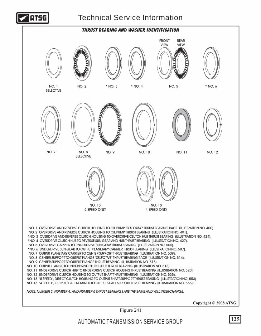
125
Copyright © 2008 ATSG
AUTOMATIC TRANSMISSION SERVICE GROUP
Technical Service Information
NO. 1SELECTIVE
NO. 2
NO. 9 NO. 10 NO. 11 NO. 12
NO. 135 SPEED ONLY
NO. 134 SPEED ONLY
* NO. 3 * NO. 4 NO. 5
NO. 7 NO. 8SELECTIVE
REARVIEW
FRONTVIEW
* NO. 6
THRUST BEARING AND WASHER IDENTIFICATION
NO. 1 OVERDRIVE AND REVERSE CLUTCH HOUSING TO OIL PUMP "SELECTIVE" THRUST BEARING RACE iLLUSTRATION NO. 400). NO. 2 OVERDRIVE AND REVERSE CLUTCH HOUSING TO OIL PUMP THRUST BEARING (ILLUSTRATION NO. 401). *NO. 3 OVERDRIVE AND REVERSE CLUTCH HOUSING TO OVERDRIVE CLUTCH HUB THRUST BEARING (ILLUSTRATION NO. 424). *NO. 4 OVERDRIVE CLUTCH HUB TO REVERSE SUN GEAR AND HUB THRUST BEARING (ILLUSTRATION NO. 427). NO. 5 OVERDRIVE CARRIER TO UNDERDRIVE SUN GEAR THRUST BEARING (ILLUSTRATION NO. 505). *NO. 6 UNDERDRIVE SUN GEAR TO OUTPUT PLANETARY CARRIER THRUST BEARING (ILLUSTRATION NO. 507). NO. 7 OUTPUT PLANETARY CARRIER TO CENTER SUPPORT THRUST BEARING (ILLUSTRATION NO. 509). NO. 8 CENTER SUPPORT TO OUTPUT FLANGE "SELECTIVE" THRUST BEARING RACE (ILLUSTRATION NO. 514). NO. 9 CENTER SUPPORT TO OUTPUT FLANGE THRUST BEARING (ILLUSTRATION NO. 515). NO. 10 OUTPUT FLANGE TO UNDERDRIVE CLUTCH HUB THRUST BEARING (ILLUSTRATION NO. 518). NO. 11 UNDERDRIVE CLUTCH HUB TO UNDERDRIVE CLUTCH HOUSING THRUST BEARING (ILLUSTRATION NO. 520). NO. 12 UNDERDRIVE CLUTCH HOUSING TO OUTPUT SHAFT THRUST BEARING (ILLUSTRATION NO. 535). NO. 13 "5 SPEED", DIRECT CLUTCH HOUSING TO OUTPUT SHAFT SUPPORT THRUST BEARING (ILLUSTRATION NO. 553) NO. 13 "4 SPEED", OUTPUT SHAFT RETAINER TO OUTPUT SHAFT SUPPORT THRUST BEARING (ILLUSTRATION NO. 555).
NOTE: NUMBER 3, NUMBER 4, AND NUMBER 6 THRUST BEARINGS ARE THE SAME AND WILL INTERCHANGE.
Figure 241
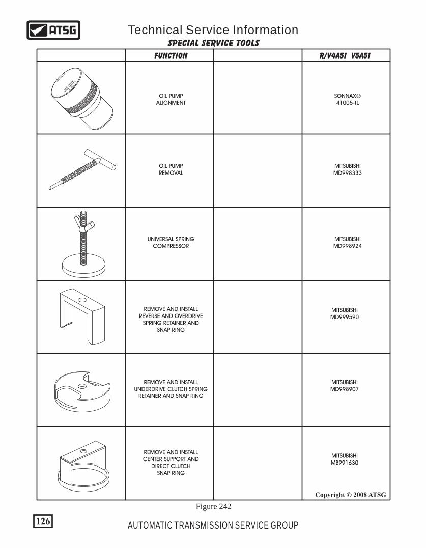
FUNCTION R/V4A51 V5A51
126
Copyright © 2008 ATSG
AUTOMATIC TRANSMISSION SERVICE GROUP
Technical Service InformationSPECIAL SERVICE TOOLS
MITSUBISHIMD998333
MITSUBISHIMD998924
UNIVERSAL SPRINGCOMPRESSOR
REMOVE AND INSTALLUNDERDRIVE CLUTCH SPRING
RETAINER AND SNAP RING
REMOVE AND INSTALLCENTER SUPPORT AND
DIRECT CLUTCHSNAP RING
REMOVE AND INSTALLREVERSE AND OVERDRIVE
SPRING RETAINER ANDSNAP RING
OIL PUMPREMOVAL
MITSUBISHIMD998907
MITSUBISHIMD999590
MITSUBISHIMB991630
SONNAX
KM
PUM
P
ALIG
NM
ENT
TOOL
SONNAX®41005-TL
OIL PUMPALIGNMENT
Figure 242
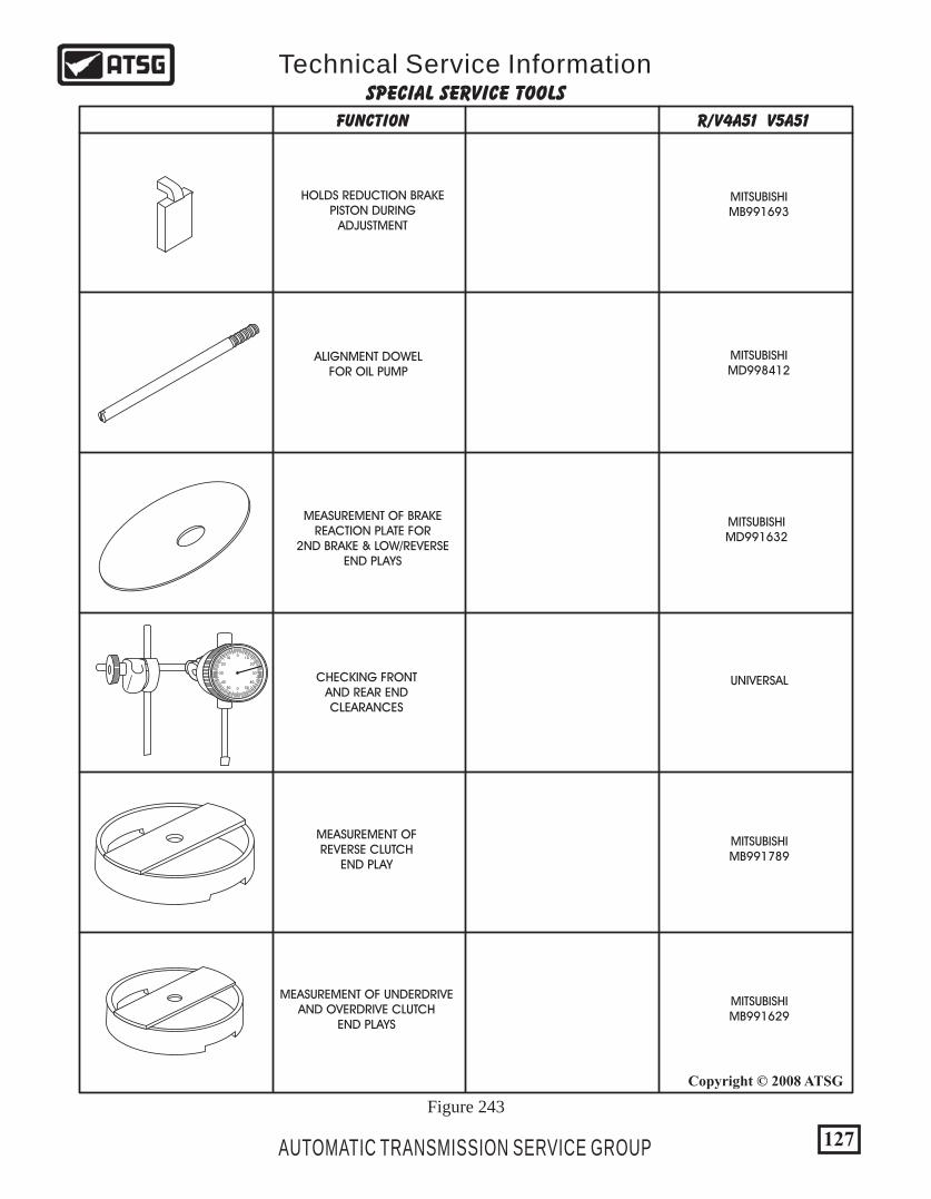
127
Copyright © 2008 ATSG
AUTOMATIC TRANSMISSION SERVICE GROUP
Technical Service InformationSPECIAL SERVICE TOOLS
FUNCTION R/V4A51 V5A51
HOLDS REDUCTION BRAKEPISTON DURING
ADJUSTMENT
ALIGNMENT DOWELFOR OIL PUMP
MEASUREMENT OF BRAKEREACTION PLATE FOR
2ND BRAKE & LOW/REVERSEEND PLAYS
UNIVERSAL
MITSUBISHIMB991789
MITSUBISHIMB991629
MITSUBISHIMD991632
MITSUBISHIMD998412
MITSUBISHIMB991693
CHECKING FRONTAND REAR ENDCLEARANCES
MEASUREMENT OFREVERSE CLUTCH
END PLAY
MEASUREMENT OF UNDERDRIVEAND OVERDRIVE CLUTCH
END PLAYS
0
0
1010
5050
2020
4040
3030
Figure 243
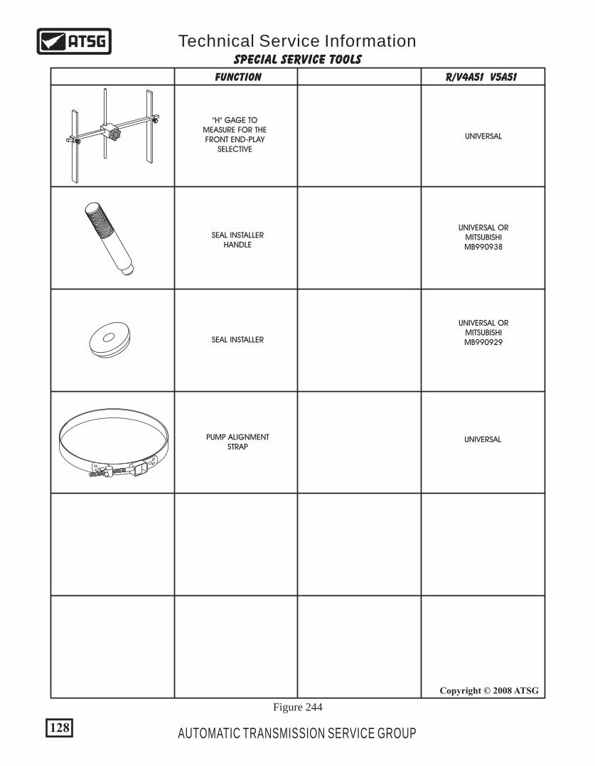
FUNCTION R/V4A51 V5A51
128
Copyright © 2008 ATSG
AUTOMATIC TRANSMISSION SERVICE GROUP
Technical Service InformationSPECIAL SERVICE TOOLS
UNIVERSAL
UNIVERSAL ORMITSUBISHIMB990929
UNIVERSAL ORMITSUBISHIMB990938
"H" GAGE TOMEASURE FOR THEFRONT END-PLAY
SELECTIVE
SEAL INSTALLERHANDLE
SEAL INSTALLER
UNIVERSALPUMP ALIGNMENTSTRAP
Figure 244