Embed Size (px)
Citation preview

Mixed Signal OscilloscopesMSO5000B, DPO5000B Series Datasheet
Designing with today’s faster data rates and tighter timing margins requiresan oscilloscope with outstanding signal acquisition performance andanalysis capabilities. Tektronix MSO/DPO5000B Series oscilloscopesprovide exceptional signal fidelity, with 2 GHz bandwidth and 10 GS/ssample rate, along with advanced analysis and math capabilities, on yourbench and in your lab. Run Windows®-based analysis software right on theoscilloscope. Point and click Visual Triggers enable you to capture complexsignals with ease. MSO models include 16 digital timing channels, and allmodels can be equipped to decode common serial protocols, providing acomprehensive view of your systems.
Key performance specifications
2 GHz, 1 GHz, 500 MHz, and 350 MHz bandwidth models
Up to 10 GS/s real-time sample rate on one or two channels and up to5 GS/s on all four channels
Up to 250 megapoint record length with MultiView zoom™
>250,000 wfms/s maximum waveform capture rate with FastAcq®acquisition
FastFrame™ segmented memory acquisition mode with up to290,000 segments and >310,000 waveforms per second capture rate
Standard 10 MΩ passive voltage probes with less than 4 pF capacitiveloading and 500 MHz or 1 GHz analog bandwidth
>11 bits vertical resolution using HiRes sampling
User-selectable bandwidth limit and DSP filters for lower noise andbetter measurement accuracy
Key analysis features
Wave inspector® controls provide easy navigation and automatedsearch of waveform data
Suite of advanced triggers, with standard Visual Trigger and Search
53 automated measurements, selectable filtering, waveform math andFFT analysis
Waveform histogram, eye diagram, TIE (jitter/timing) measurement andanalysis
User-definable math using MATLAB, Visual Studio and Excel
Optional analysis for memory, advanced jitter, serial data, power andWideband RF
Key protocol features
Trigger and decode options for mid-speed (100 Mb/s to 1 Gb/s) buses
Trigger and decode options for low-speed (<10 Mb/s) buses
Compliance test options for USB2.0, Ethernet, USB power, MOST,BroadR-Reach
Mask testing on communication, computing and video standards
Mixed signal design and analysis (MSO Series)
16 digital channels (user upgradeable)
MagniVu™ high-speed acquisition provides 60.6 ps timing resolution onall digital channels
Automated triggering, decode, and search on parallel buses
Per-channel threshold settings
www.tek.com/MSO5000 1
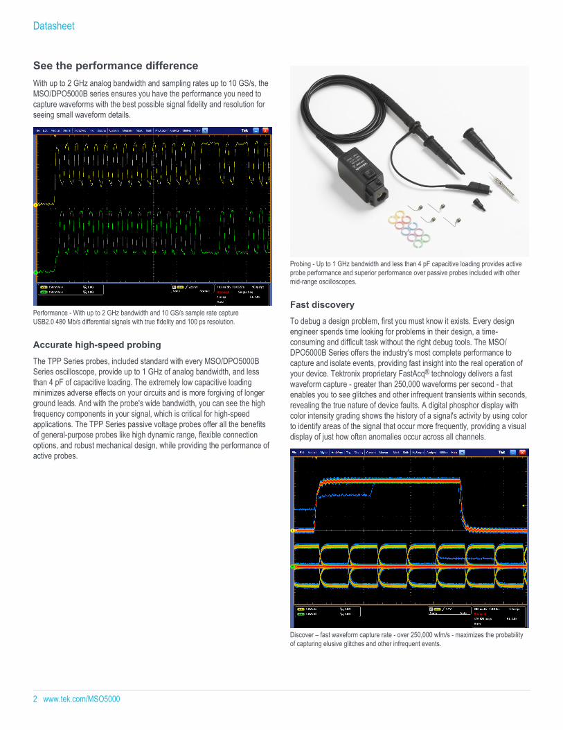
See the performance differenceWith up to 2 GHz analog bandwidth and sampling rates up to 10 GS/s, theMSO/DPO5000B series ensures you have the performance you need tocapture waveforms with the best possible signal fidelity and resolution forseeing small waveform details.
Performance - With up to 2 GHz bandwidth and 10 GS/s sample rate captureUSB2.0 480 Mb/s differential signals with true fidelity and 100 ps resolution.
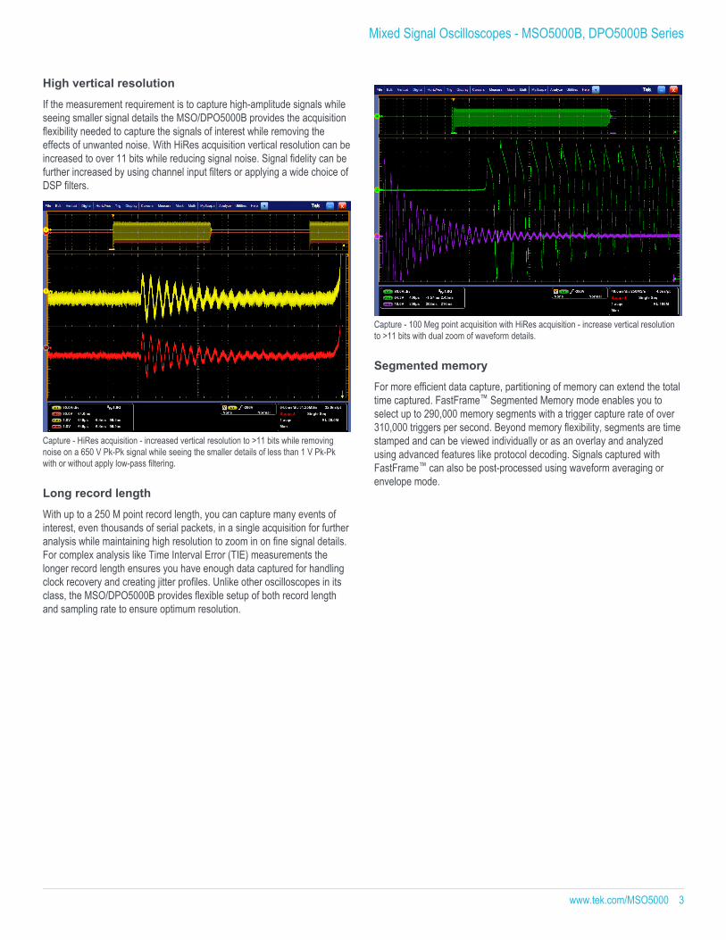
Accurate high-speed probing
The TPP Series probes, included standard with every MSO/DPO5000BSeries oscilloscope, provide up to 1 GHz of analog bandwidth, and lessthan 4 pF of capacitive loading. The extremely low capacitive loadingminimizes adverse effects on your circuits and is more forgiving of longerground leads. And with the probe's wide bandwidth, you can see the highfrequency components in your signal, which is critical for high-speedapplications. The TPP Series passive voltage probes offer all the benefitsof general-purpose probes like high dynamic range, flexible connectionoptions, and robust mechanical design, while providing the performance ofactive probes.
Probing - Up to 1 GHz bandwidth and less than 4 pF capacitive loading provides activeprobe performance and superior performance over passive probes included with othermid-range oscilloscopes.
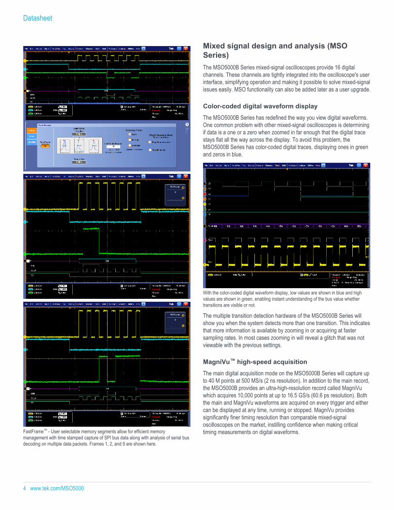
Fast discovery
To debug a design problem, first you must know it exists. Every designengineer spends time looking for problems in their design, a time-consuming and difficult task without the right debug tools. The MSO/DPO5000B Series offers the industry's most complete performance tocapture and isolate events, providing fast insight into the real operation ofyour device. Tektronix proprietary FastAcq® technology delivers a fastwaveform capture - greater than 250,000 waveforms per second - thatenables you to see glitches and other infrequent transients within seconds,revealing the true nature of device faults. A digital phosphor display withcolor intensity grading shows the history of a signal's activity by using colorto identify areas of the signal that occur more frequently, providing a visualdisplay of just how often anomalies occur across all channels.
Discover – fast waveform capture rate - over 250,000 wfm/s - maximizes the probabilityof capturing elusive glitches and other infrequent events.
Datasheet
2 www.tek.com/MSO5000
High vertical resolution
If the measurement requirement is to capture high-amplitude signals whileseeing smaller signal details the MSO/DPO5000B provides the acquisitionflexibility needed to capture the signals of interest while removing theeffects of unwanted noise. With HiRes acquisition vertical resolution can beincreased to over 11 bits while reducing signal noise. Signal fidelity can befurther increased by using channel input filters or applying a wide choice ofDSP filters.
Capture - HiRes acquisition - increased vertical resolution to >11 bits while removingnoise on a 650 V Pk-Pk signal while seeing the smaller details of less than 1 V Pk-Pkwith or without apply low-pass filtering.
Long record length
With up to a 250 M point record length, you can capture many events ofinterest, even thousands of serial packets, in a single acquisition for furtheranalysis while maintaining high resolution to zoom in on fine signal details.For complex analysis like Time Interval Error (TIE) measurements thelonger record length ensures you have enough data captured for handlingclock recovery and creating jitter profiles. Unlike other oscilloscopes in itsclass, the MSO/DPO5000B provides flexible setup of both record lengthand sampling rate to ensure optimum resolution.
Capture - 100 Meg point acquisition with HiRes acquisition - increase vertical resolutionto >11 bits with dual zoom of waveform details.
Segmented memory
For more efficient data capture, partitioning of memory can extend the totaltime captured. FastFrame™ Segmented Memory mode enables you toselect up to 290,000 memory segments with a trigger capture rate of over310,000 triggers per second. Beyond memory flexibility, segments are timestamped and can be viewed individually or as an overlay and analyzedusing advanced features like protocol decoding. Signals captured withFastFrame™ can also be post-processed using waveform averaging orenvelope mode.
Mixed Signal Oscilloscopes - MSO5000B, DPO5000B Series
www.tek.com/MSO5000 3
FastFrame™ - User selectable memory segments allow for efficient memorymanagement with time stamped capture of SPI bus data along with analysis of serial busdecoding on multiple data packets. Frames 1, 2, and 9 are shown here.
Mixed signal design and analysis (MSOSeries)The MSO5000B Series mixed-signal oscilloscopes provide 16 digitalchannels. These channels are tightly integrated into the oscilloscope's userinterface, simplifying operation and making it possible to solve mixed-signalissues easily. MSO functionality can also be added later as a user upgrade.
Color-coded digital waveform display
The MSO5000B Series has redefined the way you view digital waveforms.One common problem with other mixed-signal oscilloscopes is determiningif data is a one or a zero when zoomed in far enough that the digital tracestays flat all the way across the display. To avoid this problem, theMSO5000B Series has color-coded digital traces, displaying ones in greenand zeros in blue.
With the color-coded digital waveform display, low values are shown in blue and highvalues are shown in green, enabling instant understanding of the bus value whethertransitions are visible or not.
The multiple transition detection hardware of the MSO5000B Series willshow you when the system detects more than one transition. This indicatesthat more information is available by zooming in or acquiring at fastersampling rates. In most cases zooming in will reveal a glitch that was notviewable with the previous settings.
MagniVu™ high-speed acquisition
The main digital acquisition mode on the MSO5000B Series will capture upto 40 M points at 500 MS/s (2 ns resolution). In addition to the main record,the MSO5000B provides an ultra-high-resolution record called MagniVuwhich acquires 10,000 points at up to 16.5 GS/s (60.6 ps resolution). Boththe main and MagniVu waveforms are acquired on every trigger and eithercan be displayed at any time, running or stopped. MagniVu providessignificantly finer timing resolution than comparable mixed-signaloscilloscopes on the market, instilling confidence when making criticaltiming measurements on digital waveforms.
Datasheet
4 www.tek.com/MSO5000

The MagniVu high-resolution record provides 60.6 ps timing resolution, enabling you tomake critical timing measurements on your digital waveforms.
Versatile trigger and searchDiscovering a device fault is only the first step. Next, you must capture theevent of interest to identify root cause. The MSO/DPO5000B Seriesprovides a complete set of triggers - including runt, glitch, width, timeout,transition, pattern, state, setup/hold violation, serial packet, and paralleldata - to help quickly find your event.
Visual trigger
Finding the right characteristic of a complex signal can require hours ofcollecting and sorting through thousands of acquisitions for the event ofinterest. Defining a trigger that isolates the desired event and shows dataonly when the event occurs speeds up this process. Visual Trigger andSearch makes the identification of the desired waveform events quick andeasy by scanning through all waveform acquisitions and comparing them toon-screen areas (geometric shapes). Areas can be created using a varietyof shapes including triangles, rectangles, hexagons, trapezoids, and user-specified shapes to fit the area to the particular trigger behavior desired.Set up to eight areas and condition based on Boolean logic conditions.
Visual Trigger- Capture signals on two channels with Visual triggering with multipledefined areas and markers showing repeat occurrences.
Navigation and search
Finding your event of interest in a long waveform record can be timeconsuming without the right search tools. With today's record lengthspushing beyond a million data points, locating your event can meanscrolling through thousands of screens of signal activity.
The MSO/DPO5000B Series offers the industry's most comprehensivesearch and waveform navigation with its innovative Wave Inspector®controls. These controls speed panning and zooming through your record.With a unique force-feedback system, you can move from one end of yourrecord to the other in just seconds. User marks allow you to mark anylocation that you may want to reference later for further investigation. Or,automatically search your record for criteria you define. Wave Inspector willinstantly search your entire record, including analog, digital, and bus data.Along the way it will automatically mark every occurrence of your definedevent so you can quickly move between events. The standard AdvancedSearch and Mark capability of the MSO/DPO5000B Series can even searchfor up to eight different events simultaneously and stop a live acquisitionwhen it finds an event of interest, saving even more time.
Mixed Signal Oscilloscopes - MSO5000B, DPO5000B Series
www.tek.com/MSO5000 5
Search - Results of an advanced search for a runt pulse or a narrow glitch within a longwaveform record.
Comprehensive analysisVerifying that your prototype's performance matches simulations and meetsthe project's design goals requires analyzing its behavior. Tasks can rangefrom simple checks of rise times and pulse widths to sophisticated powerloss analysis, characterization of system clocks, and investigation of noisesources. The MSO/DPO5000B Series offers a comprehensive set ofintegrated analysis tools including waveform- and screen-based cursors,53 automated measurements, advanced waveform math including arbitraryequation editing, waveform histograms, and FFT analysis.
Analyze - Waveform histogram of the rising and falling edge of a 622 Mb/s signalshowing the distribution of edge position (jitter) over time. Included are numericmeasurements made on the waveform histogram data.
The standard limit test package enables long-term signal monitoring,characterizing signals during design, and production line testing. Limit testcompares a tested signal to a known good or "golden" version of the samesignal with user-defined vertical and horizontal tolerances. You can tailor alimit test to your specific requirements by defining test duration in a numberof waveforms, setting a violation threshold that must be met beforeconsidering a test a failure, counting hits with statistical information, andsetting actions upon violations, test failure, and test complete.
Custom analysis
When signal analysis needs extend beyond the standard or optionalanalysis features, the Microsoft Windows 10 based MSO/DPO5000B serieshas the flexibility to support custom analysis. Apply your custom algorithmsusing custom MATLAB and .NET math plug-ins for analysis functions thatare integrated in the oscilloscope user interface for more seamlessoperation.
Custom analysis - Waterfall display generated from oscilloscope data using MATLAB.
Jitter analysis
Every MSO/DPO5000B Series oscilloscope includes the DPOJETEssentials jitter and eye pattern analysis software package, extending theoscilloscope's measurement capabilities to take measurements overcontiguous clock and data cycles in a single-shot real-time acquisition. Thisenables measurement of key jitter and timing analysis parameters such asTime Interval Error and Phase Noise to help characterize possible systemtiming issues. Analysis tools such as plots for time trends and histogramsquickly show how timing parameters change over time, and spectrumanalysis quickly shows the precise frequency and amplitude of jitter andmodulation sources.
Datasheet
6 www.tek.com/MSO5000
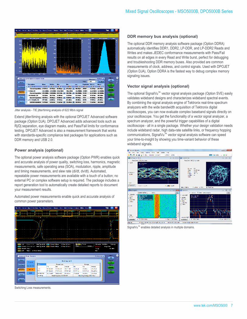
Jitter analysis - TIE jitter/timing analysis of 622 Mb/s signal
Extend jitter/timing analysis with the optional DPOJET Advanced softwarepackage (Option DJA). DPOJET Advanced adds advanced tools such asRj/Dj separation, eye diagram masks, and Pass/Fail limits for conformancetesting. DPOJET Advanced is also a measurement framework that workswith standards-specific compliance test packages for applications such asDDR memory and USB 2.0.
Power analysis (optional)
The optional power analysis software package (Option PWR) enables quickand accurate analysis of power quality, switching loss, harmonics, magneticmeasurements, safe operating area (SOA), modulation, ripple, amplitudeand timing measurements, and slew rate (di/dt, dv/dt). Automated,repeatable power measurements are available with a touch of a button; noexternal PC or complex software setup is required. The package includes areport generation tool to automatically create detailed reports to documentyour measurement results.
Automated power measurements enable quick and accurate analysis ofcommon power parameters.
Switching Loss measurements.
DDR memory bus analysis (optional)
The optional DDR memory analysis software package (Option DDRA)automatically identifies DDR1, DDR2, LP-DDR, and LP-DDR2 Reads andWrites and makes JEDEC conformance measurements with Pass/Failresults on all edges in every Read and Write burst, perfect for debuggingand troubleshooting DDR memory buses. Also provided are commonmeasurements of clock, address, and control signals. Used with DPOJET(Option DJA), Option DDRA is the fastest way to debug complex memorysignaling issues.
Vector signal analysis (optional)
The optional SignalVu™ vector signal analysis package (Option SVE) easilyvalidates wideband designs and characterizes wideband spectral events.By combining the signal analysis engine of Tektronix real-time spectrumanalyzers with the wide bandwidth acquisition of Tektronix digitaloscilloscopes, you can now evaluate complex baseband signals directly onyour oscilloscope. You get the functionality of a vector signal analyzer, aspectrum analyzer, and the powerful trigger capabilities of a digitaloscilloscope - all in a single package. Whether your design validation needsinclude wideband radar, high data-rate satellite links, or frequency hoppingcommunications, SignalVu™ vector signal analysis software can speedyour time-to-insight by showing you time-variant behavior of thesewideband signals.
SignalVu™ enables detailed analysis in multiple domains.
Mixed Signal Oscilloscopes - MSO5000B, DPO5000B Series
www.tek.com/MSO5000 7

Protocol triggering and analysis (optional)On a serial bus, a single signal often includes address, control, data, andclock information. This can make isolating events of interest difficult. TheMSO/DPO5000B Series offers a robust set of tools for debugging serialbuses with automatic trigger and decode on I2C, SPI, CAN, LIN, FlexRay,RS-232/422/485/UART, MIL-STD-1553, Ethernet, and USB 2.0, anddecode for 8b/10b, PCI Express, and MIPI D-PHY DSI-1 and CSI-2 serialbuses.
Triggering on a USB full-speed serial bus. A bus waveform provides decoded packetcontent including Start, Sync, PID, Address, End Point, CRC, Data values, and Stop.
Serial triggering
Trigger on packet content such as start of packet, specific addresses,specific data content, unique identifiers, etc. on popular serial interfacessuch as I2C, SPI, CAN, LIN, FlexRay, RS-232/422/485/UART, MIL-STD-1553, Ethernet, and USB 2.0.
Bus display
Provides a higher-level, combined view of the individual signals (clock,data, chip enable, etc.) that make up your bus, making it easy to identifywhere packets begin and end and identifying subpacket components suchas address, data, identifier, CRC, etc.
Bus decoding
Tired of having to visually inspect the waveform to count clocks, determineif each bit is a 1 or a 0, combine bits into bytes, and determine the hexvalue? Let the oscilloscope do it for you! Once you've set up a bus, theMSO/DPO5000B Series will decode each packet on the bus, and displaythe value in hex, binary, decimal (USB only) or ASCII (USB andRS-232/422/485/UART only) in the bus waveform.
Event table display
In addition to seeing decoded packet data on the bus waveform itself, youcan view all captured packets in a tabular view much like you would see ina software listing. Packets are time stamped and listed consecutively withcolumns for each component (Address, Data, etc.).
Event table showing decoded SPI serial packet data with bus timing waveform for a longacquisition.
Compliance testing
Serial bus compliance test (optional)
Software packages for automated compliance test are available forEthernet 10BASE-T, 10BASE-Te, 100BASE-TX, and 1000BASE-T (OptionET3), MOST50 and MOST150 electrical (Option MOST), BroadR-Reach/100BASE-T1 (Option BRR), and USB 2.0 (Option USB2) physical-layerdevices. These software packages enable you to conduct testing using thestandard's specified compliance tests.
USB 2.0 Compliance Testing.
Datasheet
8 www.tek.com/MSO5000

Mask testing
The optional mask test (Option MTM) software package is useful for long-term signal monitoring, characterizing signals during design, and productionline testing. The mask test software includes a robust set of masks fortelecommunications and computer standards for easily checkingcompliance to a standard. Additionally, custom masks can be created andused for characterizing signals. With mask testing you can tailor a test toyour specific requirements by defining test duration in a number ofwaveforms, setting a violation threshold that must be met beforeconsidering a test a failure, counting hits with statistical information, andsetting actions upon violations, test failure, and test complete.
Designed to make your work easier
Large, high-resolution touchscreen display
The MSO/DPO5000B Series features a 10.4 in. (264 mm) XGA colordisplay with an integrated touch screen for seeing intricate signal details.
High resolution display quality with touch screen, mouse and stylus operation.
Dedicated front panel controls
Per-channel vertical controls provide simple and intuitive operation. Nolonger do you need to share one set of vertical controls across all fourchannels.
Floating licenses
Floating licenses offer an alternative method to manage your Tektronixasset. Floating licenses allow license-key enabled options to be easilymoved among all your MSO/DPO5000, DPO7000, and DPO/DSA/MSO70000 Series of Tektronix oscilloscopes. Floating licenses areavailable for many license-key enabled options. To order a floating versionof an option license add “DPOFL-“ prefix to the option name. (e.g. DPOFL-ET3)
Check www.tek.com for additional information about floating licenseoptions.
Easy data storage
Two USB 2.0 host ports on the front panel enable easy transfer ofscreenshots, instrument settings, and waveform data to a USB flash drive.
The rear panel contains four additional USB 2.0 host ports and a USBdevice port for controlling the oscilloscope remotely from a PC or forconnecting USB peripherals. An integrated 10/100/1000BASE-T Ethernetport enables easy connection to networks and a Video Out port to drive anexternal monitor or projector. A standard ≥ 480 GB removable solid statedisk drive makes customizing settings for different users easy and enablesuse in secure environments.
Connectivity and remote operation
There are many ways to connect to your MSO/DPO5000B Seriesoscilloscope to conduct extended analysis. The first makes use of theWindows Remote Desktop capability – connect directly to your oscilloscopeand operate the user interface remotely through the built-in RemoteDesktop. A second way to connect is through Tektronix OpenChoice®software which makes use of the fast embedded bus, transferringwaveform data directly from acquisition to analysis applications on theWindows desktop at much faster speeds than conventional GPIB transfers.
Industry-standard protocols, such as TekVISA™ interface and ActiveXcontrols are included for using and enhancing Windows applications fordata analysis and documentation. IVI-COM instrument drivers are includedto enable easy communication with the oscilloscope using GPIB, serialdata, and LAN connections from programs running on the instrument or anexternal PC. Or, use the Software Developer's Kit (SDK) to help createcustom software to automate multistep processes in waveform collectionand analysis with Visual BASIC, C, C++, MATLAB, LabVIEW,LabWindows/CVI, and other common Application DevelopmentEnvironments (ADE).
Mixed Signal Oscilloscopes - MSO5000B, DPO5000B Series
www.tek.com/MSO5000 9
TekScope Anywhere™ off-line analysis
TekScope Anywhere™ brings the power of the oscilloscope analysisenvironment to the PC. Users now have the flexibility to perform analysistasks including timing, eye, and jitter analysis outside the lab. Waveformdata and setups 1 from Tektronix MDO3000, MDO4000, MSO/DPO5000,DPO7000C, or MSO/DPO70000C/D/DX/SX Series oscilloscopes canquickly be shared among team members and remote sites, resulting inimproved efficiency.
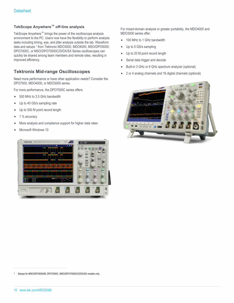
Tektronix Mid-range OscilloscopesNeed more performance or have other application needs? Consider theDPO7000, MDO4000, or MDO3000 series.
For more performance, the DPO7000C series offers:
500 MHz to 3.5 GHz bandwidth
Up to 40 GS/s sampling rate
Up to 500 M point record length
1 % accuracy
More analysis and compliance support for higher data rates
Microsoft Windows 10
For mixed-domain analysis or greater portability, the MDO4000 andMDO3000 series offer:
100 MHz to 1 GHz bandwidth
Up to 5 GS/s sampling
Up to 20 M point record length
Serial data trigger and decode
Built-in 3 GHz or 6 GHz spectrum analyzer (optional)
2 or 4 analog channels and 16 digital channels (optional)
1 Setups for MSO/DPO5000/B, DPO7000C, MSO/DPO70000C/D/DX/SX models only.
Datasheet
10 www.tek.com/MSO5000

SpecificationsAll specifications are guaranteed unless noted otherwise. All specifications apply to all models unless noted otherwise.
Model overview
MSO5034BDPO5034B
MSO5054BDPO5054B
MSO5104BDPO5104B
MSO5204BDPO5204B
Input Channels 4 Bandwidth 350 MHz 500 MHz 1 GHz 2 GHzRise Time (Calculated) 1 ns 700 ps 350 ps 175 psDC Gain Accuracy ±1.5%, derated at 0.10%/°C above 30 °CBandwidth Limits Depending on instrument model: 1 GHz, 500 MHz, 350 MHz, 250 MHz, and 20 MHzEffective Number of Bits (Typical) 6 bits (10 divisionp-p sine wave input at instrument bandwidth, 100 mV/div, 50 Ω Input Impedance, maximum sample rate, 1 k
point record length)Random Noise (RMS, typical, sample mode, full BW, 50 Ω)
1 mV/div 173 μV 178 μV 68 μV 70 μV2 mV/div 216 μV 236 μV 128 μV 158 μV5 mV/div 231 μV 281 μV 214 μV 307 μV10 mV/div 305 μV 340 μV 315 μV 485 μV20 mV/div 504 μV 523 μV 547 μV 791 μV50 mV/div 1.15 mV 1.17 mV 1.29 mV 1.82 mV100 mV/div 2.40 mV 2.46 mV 3.08 mV 4.75 mV1 V/div 22.96 mV 22.98 mV 23.15 mV 29.58 mV
Maximum Sample Rate (All channels) 5 GS/s 5 GS/s 5 GS/s 5 GS/sMaximum Sample Rate (1 or2 channels)
5 GS/s 5 GS/s 10 GS/s 10 GS/s
Maximum Equivalent Time SamplingRate
400 GS/s
Maximum Record Length withStandard Configuration
25 M 25 M (4 ch)50 M (1 or 2 ch)
Maximum Record Length with Option5RL
50 M 50 M (4 ch)125 M (1 or 2 ch)
Maximum Record Length with Option10RL
125 M 125 M (4 ch)250 M (1 or 2 ch)
Vertical system analog channels
Input coupling AC, DC
Input resistance 1 MΩ ±1%, 50 Ω ±1%
Input sensitivity range 1 MΩ: 1 mV/div to 10 V/div
50 Ω: 1 mV/div to 1 V/div
Vertical resolution 8 bits (>11 bits with Hi Res)
Mixed Signal Oscilloscopes - MSO5000B, DPO5000B Series
www.tek.com/MSO5000 11

Maximum input voltage, 1 MΩ 300 VRMS CAT II, with peaks ≤ ±425 V
For <100 mV/div derate at 20 dB/decade above 100 kHz to 30 VRMS at 1 MHz, 10 dB/decade above 1 MHz
For ≥100 mV/div derate at 20 dB/decade above 3 MHz to 30 VRMS at 30 MHz, 10 dB/decade above 30 MHz
Maximum input voltage, 50 Ω 5 VRMS, with peaks ≤ ±20 V
Position range ±5 divisions
Delay between any Two Channels(Typical)
≤100 ps (50 Ω, DC coupling and equal V/div at or above 10 mV/div)
Offset range1 mV/div - 50 mV/div 1 MΩ: ±1 V
50 Ω: ±1 V50.5 mV/div - 99.5 mV/div 1 MΩ: ±0.5 V
50 Ω: ±0.5 V100 mV/div - 500 mV/div 1 MΩ: ±10 V
50 Ω: ±10 V505 mV/div - 995 mV/div 1 MΩ: ±5 V
50 Ω: ±5 V1 V/div - 5 V/div 1 MΩ: ±100 V
50 Ω: ±5 V5.05 V/div - 10 V/div 1 MΩ: ±50 V
50 Ω: NA
Offset Accuracy ±(0.005 × |offset – position| + DC Balance)
Note: Both position and constant offset term must be converted to volts by multiplying by the appropriate volts/div term
Channel-to-channel isolation (Anytwo channels at equal verticalscale settings) (typical)
≥100:1 at ≤100 MHz and ≥30:1 at >100 MHz up to the rated BW
Vertical system digital channels
Input Channels 16 Digital (D15 - D0)
Thresholds Per-channel Thresholds
Threshold Selections TTL, ECL, User
User-defined Threshold Range ±40 V
Threshold Accuracy ±(100 mV + 3% of threshold setting)
Maximum Input Voltage ±42 Vpeak
Input Dynamic Range 30 Vp-p ≤200 MHz
10 Vp-p >200 MHz
Minimum Voltage Swing 400 mV
Datasheet
Vertical system analog channels
12 www.tek.com/MSO5000

Input Impedance 100 kΩ
Probe Loading 3 pF
Vertical Resolution 1 bit
Horizontal system analog channels
Maximum Duration at HighestReal-Time Sample Rate
25 ms
Time Base Range 12.5 ps/div to 8,000,000 s/div
Time resolution (in ET/IT mode) 2.5 ps/div
Time base delay time range –10 divisions to 1000 s
Channel-to-channel deskew range ±75 ns
Time base accuracy ±5 ppm over any ≥1 ms interval
Horizontal system digital channels
Maximum Sample Rate (Main) 500 MS/s (2 ns resolution)
Maximum record length (main) 25 M Standard
Up to 40 M with Record Length options
Maximum sample rate (MagniVu) 16.5 GS/s (60.6 ps resolution)
Maximum record length (MagniVu) 10k points centered around the trigger
Minimum detectable pulse width 1 ns
Channel-to-channel skew (typical) 200 ps
Maximum input toggle rate 500 MHz at minimum input swing; higher toggle rates can be achieved at higher amplitudes
Trigger system
Main trigger modes Auto, Normal, and Single
Trigger coupling DC, AC, HF Rej (attenuates >50 kHz), LF Rej (attenuates <50 kHz), Noise Reject (reduces sensitivity)
Trigger holdoff range 250 ns to 8 s
Enhanced triggering User-selectable; corrects the difference in timing between the trigger path and the acquired data (not available in FastAcq)
Trigger jitter ≤100 fsRMS using Enhanced Trigger
≤10 psRMS without Enhanced Trigger and in Fast Acq mode
≤100 psRMS for non-Edge-type trigger modes
Mixed Signal Oscilloscopes - MSO5000B, DPO5000B Series
Vertical system digital channels
www.tek.com/MSO5000 13
Trigger sensitivityInternal DC coupled For 1 MΩ: 1 mV/div to 4.98 mV/div: 0.75 div from DC to 50MHz, increasing to 1.3 div at instrument bandwidth ≥5 mV/div: 0.40 div
from DC to 50 MHz, increasing to 1 div at instrument bandwidth
For 50 Ω (MSO5204, DPO5204, MSO5104, DPO5104): 0.40 div from DC to 50 MHz, increasing to 1 div at instrument bandwidth
For 50 Ω (MSO5054, DPO5054, MSO5034, DPO5034): 1 mV/div to 4.98 mV/div: 0.75 div from DC to 50MHz, increasing to 1.3 divat instrument bandwidth ≥5 mV/div: 0.40 div from DC to 50 MHz, increasing to 1 div at instrument bandwidth
External (auxiliary input) 1 MΩ 200 mV from DC to 50 MHz, increasing to 500 mV at 250 MHz
Trigger level rangeAny channel ±8 divisions from center of screenExternal (auxiliary input) ±8 VLine Fixed at about 50% of line voltage
Trigger modesEdge Positive, negative, or either slope on any channel or front-panel auxiliary input. Coupling includes DC, AC, HF reject, LF reject, and
noise rejectGlitch Trigger on or reject glitches of positive, negative, or either polarity. Programmable glitch width is 4 ns minimum to 8 s maximumRunt Trigger on a pulse that crosses one threshold but fails to cross a second threshold before crossing the first againWidth Trigger on width of positive or negative pulse either within or outside selectable limits (4 ns to 8 s)Timeout Trigger on an event which remains high, low, or either, for a specified time period (4 ns to 8 s)Transition Trigger on pulse edge rates that are faster or slower than specified. Slope may be positive, negative, or eitherSetup/Hold Trigger on violations of both setup time and hold time between clock and data present on any two input channelsPattern Trigger when any logical pattern of signals goes false or stays true for specified period of time (4 ns to 1 s). Pattern (AND, OR,
NAND, NOR) specified for all analog and digital input channels defined as High, Low, or Don't CareParallel Bus Trigger on specified data value on defined parallel busState Any logical pattern of analog channels and digital channels (MSO models) clocked by edge on another channel. Trigger on rising
or falling clock edgeVideo Trigger on all lines, specific line number, odd, even, or all fields on NTSC, PAL, SECAM, and HDTV 480p/60, 576p/50, 875i/60,
720p/30, 720p/50, 720p/60, 1080/24sF, 1080i/50, 1080p/25, 1080i/60, 1080p/24, 1080p/25, 1080p/50, 1080p/60, Bi-level, Tri-levelTrigger Sequences Main, Delayed by Time, Delayed by Events. All sequences can include separate horizontal delay after the trigger event to position
the acquisition window in timeA/B Sequence Event TriggerTypes
Edge
Trigger Delay by Time 4 ns to 8 sTrigger Delay by Events 1 to 4,000,000 eventsVisual Trigger Trigger on up to 8 user-specified areas, including rectangle, triangle, trapezoid, hexagon, and user-specified shapes on any of the
analog channelsI2C (Optional) Provided as part of Opt. SR-EMBD. Trigger on Start, Repeated Start, Stop, Missing ACK, Address (7 or 10 bit), Data, or Address
and Data on I2C buses up to 10 Mb/sSPI (Optional) Provided as part of Opt. SR-EMBD. Trigger on Slave Select, Idle Time, or Data (1-16 words) on SPI buses up to 10 Mb/sCAN (Optional) Provided as part of Opt. SR-AUTO. Trigger on Start of Frame, Type of Frame (Data, Remote, Error, or Overload), Identifier, Data,
Identifier and Data, EOF, Missing Ack, Bit Stuff Error, and CRC Error on CAN buses up to 1 Mb/sLIN (Optional) Provided as part of Opt. SR-AUTO. Trigger on Sync, Identifier, Data, Identifier and Data, Wakeup Frame, Sleep Frame, and Error
on LIN buses up to 1 Mb/sFlexRay (Optional) Provided as part of Opt. SR-AUTO. Trigger on Indicator Bits (Normal, Payload, Null, Sync, Startup), Cycle Count, Header Fields
(Indicator Bits, Identifier, Payload Length, Header CRC, and Cycle Count), Identifier, Data, Identifier and Data, End Of Frame, andError on FlexRay buses up to 10 Mb/s
MIL-STD-1553 (Optional) Provided as part of Opt. SR-AERO. Trigger on Sync, Command Word, Status Word, Data Word, Idle Time, and Error on MIL-STD-1553 buses up to 1 Mb/s
Datasheet
Trigger system
14 www.tek.com/MSO5000

Ethernet (Optional) Provided as part of Opt. SR-ENET. Trigger on Start of Packet, MAC Address, MAC Q-tag, MAC Length/Type, MAC Data, IPHeader, TCP Header,
TCP/IPV4 Data, End of Packet, and FCS(CRC) Error on 10BASE-T and 100BASE-TX buses.RS-232/422/485/UART(Optional)
Provided as part of Opt. SR-COMP. Trigger on Start Bit, End of Packet, Data, and Parity Error up to 10 Mb/s
USB 2.0 Low Speed:(Optional)
Provided as part of Opt. SR-USB.
Trigger on Sync, Reset, Suspend, Resume, End of Packet, Token (Address) Packet, Data Packet, Handshake Packet, SpecialPacket, Error.
Token Packet Trigger – Any token type, SOF, OUT, IN, SETUP; Address can be specified for Any, OUT, IN, and SETUP tokentypes. Address can be further specified to trigger on ≤, <, =, >, ≥, != a particular value, or inside or outside a range. Frame numbercan be specified for SOF token using Binary, Hex, Unsigned Decimal, and Don't Care digits.
Data Packet Trigger – Any data type, DATA0, DATA1; Data can be further specified to trigger on ≤, <, =, >, ≥, != a particular datavalue, or inside or outside a range.
Handshake Packet Trigger – Any handshake type, ACK, NAK, STALL.
Special Packet Trigger – Any special type, Reserved.
Error Trigger – PID Check, CRC5 or CRC16, Bit Stuffing.USB 2.0 Full Speed: (Optional) Provided as part of Opt. SR-USB.
Trigger on Sync, Reset, Suspend, Resume, End of Packet, Token (Address) Packet, Data Packet, Handshake Packet, SpecialPacket, Error.
Token Packet Trigger – Any token type, SOF, OUT, IN, SETUP; Address can be specified for Any, OUT, IN, and SETUP tokentypes. Address can be further specified to trigger on ≤, <, =, >, ≥, != a particular value, or inside or outside a range. Frame numbercan be specified for SOF token using Binary, Hex, Unsigned Decimal, and Don't Care digits.
Data Packet Trigger – Any data type, DATA0, DATA1; Data can be further specified to trigger on ≤, <, =, >, ≥, != a particular datavalue, or inside or outside a range.
Handshake Packet Trigger – Any handshake type, ACK, NAK, STALL.
Special Packet Trigger – Any special type, PRE, Reserved.
Error Trigger – PID Check, CRC5 or CRC16, Bit Stuffing.USB 2.0 High Speed:(Optional)
Provided as part of Opt. SR-USB.
Trigger on Sync, Reset, Suspend, Resume, End of Packet, Token (Address) Packet, Data Packet, Handshake Packet, SpecialPacket, Error.
Token Packet Trigger – Any token type, SOF, OUT, IN, SETUP; Address can be specified for Any, OUT, IN, and SETUP tokentypes. Address can be further specified to trigger on ≤, <, =, >, ≥, != a particular value, or inside or outside a range. Frame numbercan be specified for SOF token using Binary, Hex, Unsigned Decimal, and Don't Care digits.
Data Packet Trigger – Any data type, DATA0, DATA1, DATA2, DATAM; Data can be further specified to trigger on ≤, <, =, >, ≥, !=a particular data value, or inside or outside a range.
Handshake Packet Trigger – Any handshake type, ACK, NAK, STALL, NYET.
Special Packet Trigger – Any special type, ERR, SPLIT, PING, Reserved. SPLIT packet components that can be specified include:
Hub Address
Start/Complete – Don't Care, Start (SSPLIT), Complete (CSPLIT) Port Address
Start and End bits – Don't Care, Control/Bulk/Interrupt (Full-speed Device, Low-speed Device), Isochronous (Data is Middle, Datais End, Data is Start, Data is All)
Endpoint Type – Don't Care, Control, Isochronous, Bulk, Interrupt
Error Trigger – PID Check, CRC5, CRC16, Any.
Note: USB 2.0 High-speed triggering, decoding, and search only available on 1 GHz and 2 GHz models.
Mixed Signal Oscilloscopes - MSO5000B, DPO5000B Series
Trigger system
www.tek.com/MSO5000 15

Acquisition system
Acquisition modesSample Acquire sampled valuesPeak detect Captures narrow glitches as narrow as 100 ps (2 GHz and 1 GHz models) or 200 ps (500 MHz and 350 MHz models) at all real-
time sampling ratesAveraging From 2 to 10,000 waveforms included in averageEnvelope Min-Max envelope reflecting Peak Detect data over multiple acquisitionsHi-Res Real-time boxcar averaging reduces random noise and increases resolutionRoll mode Scrolls sequential waveform points across the display in a right-to-left rolling motion at sweep speeds slower than 50 ms/div. Up to
20 MS/s with a maximum record length of 10 MFastAcq® FastAcq optimizes the instrument for analysis of dynamic signals and capture of infrequent eventsMaximum FastAcq waveformcapture rate
>250,000 wfms/s on all 4 channels simultaneously
Waveform database Accumulate waveform database providing three-dimensional array of amplitude, time, and countsFastFrame™ Acquisition memory divided into segments; maximum trigger rate >310,000 waveforms per second. Time of arrival recorded with
each event. Frame finder tool helps to visually identify transients
Automated Search and Mark Automatically mark events and document waveforms. Search positive/negative slopes or both, glitches, runts, pulse widths,transition rate, setup and hold, timeout, windows, or find any logic or state pattern, up to 8 different event types on any of the4 analog channels. Search DDR Read or Write bursts with Opt. DDRA. Event table summarizes all found events. All events aretime stamped in reference to trigger position. Stop acquisitions when an event is found
Waveform analysis
Waveform measurementsCursors Waveform and ScreenAutomatic measurements 53, of which 8 can be displayed on-screen at any one time. Measurements include: Period, Frequency, Delay, Rise Time, Fall
Time, Positive Duty Cycle, Negative Duty Cycle, Positive Width, Negative Width, Burst Width, Phase, Positive Overshoot, NegativeOvershoot, Peak-to-Peak, Amplitude, High, Low, Maximum, Minimum, Mean, Cycle Mean, RMS, Cycle RMS, Area, Cycle Area
Eye-pattern measurements Extinction Ratio (absolute, %, dB), Eye Height, Eye Width, Eye Top, Eye Base, Crossing %, Jitter (p-p, RMS, 6sigma), Noise (p-p,RMS), Signal/Noise Ratio, Cycle Distortion, Q-Factor
Measurement statistics Mean, Minimum, Maximum, Standard DeviationReference levels User-definable reference levels for automatic measurements can be specified in either percent or unitsGating Isolate the specific occurrence within an acquisition to take measurements on, using either screen or waveform cursorsWaveform histogram A waveform histogram provides an array of data values representing the total number of hits inside a user-defined region of the
display. A waveform histogram is both a visual graph of the hit distribution and a numeric array of values that can be measured.Sources – Channel 1, Channel 2, Channel 3, Channel 4, Ref 1, Ref 2, Ref 3, Ref 4,Math 1,Math 2,Math 3,Math 4
Types – Vertical, HorizontalWaveform histogrammeasurements
Waveform Count, Hits in Box, Peak Hits, Median, Maximum, Minimum, Peak-to-Peak, Mean (μ), Standard Deviation (sigma),μ +1sigma, μ +2sigma, μ +3sigma
Waveform processing/mathArithmetic Add, Subtract, Multiply, Divide waveforms and scalarsAlgebraic expressions Define extensive algebraic expressions including waveforms, scalars, user-adjustable variables, and results of parametric
measurements. Perform math on math using complex equations. e.g. (Integral (CH1 – Mean(CH1)) × 1.414 × VAR1)Math functions Average, Invert, Integrate, Differentiate, Square Root, Exponential, Log10, Log e, Abs, Ceiling, Floor, Min, Max, Sin, Cos, Tan,
ASin, ACos, ATan, Sinh, Cosh, TanhRelational Boolean result of comparison >, <, ≥, ≤, ==, !=Frequency domain functions(FFT)
Spectral Magnitude and Phase, Real and Imaginary Spectra
FFT vertical units Magnitude: Linear, dB, dBm
Phase: Degrees, radians, group delay
Datasheet
16 www.tek.com/MSO5000

FFT window functions Rectangular, Hamming, Hanning, Kaiser-Bessel, Blackman-Harris, Gaussian, Flattop2, Tek ExponentialWaveform definition As an arbitrary math expressionFiltering functions User-definable filters. Users specify a filter containing the coefficients of the filter. Filter files providedCustom math functions Custom MATLAB and .NET plug-ins can be included in the math waveform definitionMask function A function that generates a waveform database pixmap from a sample waveform. Sample count can be defined
Software
IVI driver Provides a standard instrument programming interface for common applications such as LabVIEW, LabWindows/CVI,Microsoft .NET and MATLAB. IVI-COM standard
LXI Class C web interface Connect to the MSO/DPO5000B Series through a standard Web browser by simply entering the oscilloscope's IP address in theaddress bar of the browser. The web interface enables viewing of instrument status and configuration, as well as status andmodification of network settings. All web interaction conforms to LXI Class C specification
Display system
Display type 10.4 in. (264 mm) liquid-crystal active-matrix color display with touch screen
Display resolution 1024 horizontal × 768 vertical pixels (XGA)
Waveform styles Vectors, dots, variable persistence, infinite persistence
Color palettes Normal, green, gray, temperature, spectral, and user defined
Display format YT, XY
Computer system
Operating system Microsoft Windows 10 Enterprise IoT Edition
CPU Intel i5-4400E 2.7 GHz processor
PC system memory ≥4 GB
Solid state disk drive Removable solid state disk drive, 512 GB
Mouse Optical wheel mouse, USB interface
Keyboard Order 119-7083-xx for small keyboard; USB interface and hub
Mixed Signal Oscilloscopes - MSO5000B, DPO5000B Series
Waveform analysis
www.tek.com/MSO5000 17

Input output ports
USB 2.0 High-speed host ports Supports USB mass storage devices, printers, keyboard, and mouse. Two ports on front and four ports on rear of instrument. Canbe disabled individually
USB 1.1 Full-speed device port Rear-panel connector allows for communication/control of oscilloscope through USBTMC or GPIB (with a TEK-USB-488 adapter)
LAN port RJ-45 connector, supports 10/100/1000BASE-T
Video out port DB-15 female connector, connect to show the oscilloscope display on an external monitor or projector. Support for extendeddesktop and clone mode
Audio ports Miniature phono jacks
Keyboard port PS/2 compatible
Mouse port PS/2 compatible
Auxiliary input Front-panel BNC connector. Input impedance 1 MΩ. Max input 300 VRMS with peaks ≤ ±425 V
Auxiliary out (software switchable) Trigger Out: A TTL compatible pulse when the oscilloscope triggers
Time Base Reference Out: A TTL compatible output of internal 10 MHz reference oscillator
External reference in Time base system can phase lock to an external 10 MHz reference (10 MHz ±1%)
Probe compensator output Front-panel pins
Amplitude: 2.5 V
Frequency: 1 kHz
LAN eXtensions forInstrumentation (LXI)
Class: LXI Class C Version: 1.3
Optional TekVPI® external powersupply
Required when total oscilloscope probe power usage exceeds 15 W.
Output Voltage 12 VOutput Current 5 APower Consumption 50 W
Power source
Power source voltage 100 to 240 V ±10%
Power source frequency 45 Hz to 66 Hz (85 to 264 V)
360 Hz to 440 Hz (100 to 132 V)
Power consumption 275 W maximum
Datasheet
18 www.tek.com/MSO5000
Physical characteristics
Dimensions mm in.Height 233 9.16 Width 439 17.29 Depth 206 8.12
Weight kg lb.Net 6.7 14.9 Shipping 12.5 27.5
Rackmount configuration 5U
Cooling clearance in. mmTop 0 0 Bottom 0 0 Left Side 2 51 Right Side 0 0 Front 0 0 Rear 2 51
EMC environmental and safety
TemperatureOperating 0 °C to +50 °CNonoperating –20 °C to +60 °C
HumidityOperating 8% to 90% relative humidity with a maximum wet-bulb temperature of 29 °C at or below +50 °C (upper limit de-rates to 20.6%
relative humidity at +50 °C). NoncondensingNonoperating 5% to 98% relative humidity with a maximum wet-bulb temperature of 40 °C at or below +60 °C (upper limit de-rates to 29.8%
relative humidity at +60 °C). Noncondensing
AltitudeOperating 3,000 m (9,843 ft.)Nonoperating 9,144 m (30,000 ft.)
RegulatoryElectromagnetic compatibility 2004/108/ECCertifications UL61010-1; CSA61010-1, EN61010-1; IEC 61010-1
Mixed Signal Oscilloscopes - MSO5000B, DPO5000B Series
www.tek.com/MSO5000 19
Ordering information
DPO5000B modelsDPO5034B 350 MHz, 5 GS/s, 25 M record length, 4-channel digital phosphor oscilloscope
DPO5054B 500 MHz, 5 GS/s, 25 M record length, 4-channel digital phosphor oscilloscope
DPO5104B 1 GHz, 10/5 GS/s (2/4 ch), 50 M/25 M record length, 4-channel digital phosphor oscilloscope
DPO5204B 2 GHz, 10/5 GS/s (2/4 ch), 50 M/25 M record length, 4-channel digital phosphor oscilloscope
MSO5000B modelsMSO5034B 350 MHz, 5 GS/s, 25 M record length, 4+16 channel mixed signal oscilloscope
MSO5054B 500 MHz, 5 GS/s, 25 M record length, 4+16 channel mixed signal oscilloscope
MSO5104B 1 GHz, 10/5 GS/s (2/4 ch), 50 M/25 M record length, 4+16 channel mixed signal oscilloscope
MSO5204B 2 GHz, 10/5 GS/s (2/4 ch), 50 M/25 M record length, 4+16 channel mixed signal oscilloscope
Standard accessoriesTPP0500B One passive voltage probe per analog channel (500 MHz, 10X, 3.9 pF) for 500 MHz and 350 MHz models
TPP1000 One passive voltage probe per analog channel (1 GHz, 10X, 3.9 pF) for 2 GHz and 1 GHz models
200-5130-xx Front cover
119-6107-xx Touch-screen stylus
071-298x-xx User Manual (please specify language when ordering)
— Advanced Search and Mark, DPOJET Essentials, Visual Trigger and Search, and Limit Test all included standard
— Accessory pouch
— Mouse
— Calibration Certificate documenting measurement traceability to National Metrology Institute(s), Z 540-1 Compliance and ISO9001
— Power Cord (please specify power plug option when ordering)
— One-year warranty
P6616 16-channel logic probe for MSO Models
020-2662-xx Logic probe accessory kit for MSO Models
OptionsRecord length options Option MSO5034B
DPO5034BMSO5054BDPO5054B
MSO5104BDPO5104BMSO5204BDPO5204B
Opt. 5RL 50 M/Ch 125 M max, 50 M/ChOpt. 10RL 125 M/Ch 250 M max, 125 M/Ch
Datasheet
20 www.tek.com/MSO5000
Advanced analysis optionsOption DescriptionOpt. BRR BroadR-Reach/100BASE-T1 Compliance Testing (Requires TF-GBE-BTP and TF-BRR-CFD Test Fixtures) (Available on 1 GHz and 2 GHz
models only.)Opt. DDRA DDR Memory bus analysis (Requires Opt. DJA) (Available on 1 GHz and 2 GHz models only.)Opt. DJA Jitter and Eye Analysis Tools – Advanced (DPOJET)Opt. DJAN DPOJET Noise, jitter, and eye analysis tools (Requires Opt. DJA)Opt. ET3 Ethernet compliance test (Requires TF-GBE-BTP or TF-GBE-ATP Ethernet Test Fixture)Opt. MOST MOST Essentials – Electrical compliance and debug test solution for MOST50 and MOST150 (Requires Opt. DJA)Opt. MTM Mask testing
– ITU-T (64 Kb/s to 155 Mb/s)– ANSI T1.102 (1.544 Mb/s to 155 Mb/s)– Ethernet IEEE 802.3, ANSI X3.263 (125 Mb/s to1.25 Gb/s)– SONET/SDH (51.84 Mb/s to 622 Mb/s)– Fibre Channel (133 Mb/s to 2.125 Gb/s)– Fibre Channel Electrical (133 Mb/s to 1.06 Gb/s)– USB (12 Mb/s to 480 Mb/s)– IEEE 1394b (491.5 Mb/s to 1.966 Gb/s)– Rapid I/O Serial (up to 1.25 Gb/s)– Rapid I/O LP-LVDS (500 Mb/s to 1 Gb/s)– OIF Standards (1.244 Gb/s)– CPRI, V4.0 (1.228 Gb/s)– Video (143.18 Mb/s to 360 Mb/s)
Opt. PWR Power measurement and analysisOpt. SR-AERO Aerospace serial triggering and analysis (MIL-STD-1553).
Enables triggering on packet-level information on MIL-STD-1553 buses and analytical tools such as bus views, packet decoding, search tools,and packet decode tables with time stamp information.Signal Inputs – Any Ch1 - Ch4Recommended probing – Differential
Opt. SR-AUTO Automotive serial triggering and analysis (CAN/LIN/FlexRay).Enables triggering on packet-level information on CAN, LIN, and FlexRay buses and analytical tools such as digital views of the signal, bus views,packet decoding, search tools, and packet decode tables with time stamp information.Signal Inputs – Any Ch1 - Ch4 (and any D0 - D15 on MSO models)Recommended probing – LIN: single-ended; CAN/FlexRay: differential
Opt. SR-COMP Computer serial triggering and analysis (RS-232/422/485/UART)Enables triggering on packet-level information on RS-232/422/485/UART buses and analytical tools such as digital views of the signal, bus views,packet decoding, search tools, and packet decode tables with time stamp information.Signal Inputs – Any Ch1 - Ch4 (and any D0 - D15 on MSO models)Recommended probing – RS-232/UART: single ended; RS-422/485: differential
Opt. SR-DPHY MIPI® D-PHY serial analysis.Enables analysis of MIPI DSI-1 and CSI-2 buses with analytical tools such as digital views of the signal, bus views, packet decoding, searchtools, and packet decode tables with time stamp information.Signal Inputs – Any Ch1 - Ch4Recommended probing – Differential
Opt. SR-EMBD Embedded serial triggering and analysis (I2C, SPI)Enables triggering on packet-level information on I2C and 2-wire and 3-wire SPI buses and analytical tools such as digital views of the signal, busviews, packet decoding, search tools, and packet decode tables with time stamp information.Signal Inputs – I2C: Any Ch1 - Ch4 (and any D0 - D15 on MSO models); SPI: Any Ch1 - Ch4 (and any D0 - D15 on MSO models)Recommended probing – I2C, SPI: single ended
Opt. SR-ENET Ethernet serial triggering and analysis (10BASE-T, 100BASE-TX)Enables triggering on packet-level information on Ethernet buses as well as analytical tools such as bus views, packet decoding, search tools,and packet decode tables with time stamp information.Signal Inputs – Any Ch1 - Ch4.Recommended probing – Differential
Mixed Signal Oscilloscopes - MSO5000B, DPO5000B Series
www.tek.com/MSO5000 21

Option DescriptionOpt. SR-USB USB 2.0 serial triggering and analysis (LS, FS, HS)
Enables triggering on packet-level content for low-speed, full-speed, and high-speed USB serial buses. Also enables analytical tools such as busviews, packet decoding, search tools, and packet decode tables with time stamp information for low-speed, full-speed, and high-speed USB serialbuses.Signal Inputs – Low-speed and Full-speed: Any Ch1 - Ch4 (and any D0 - D15 on MSO models) for single ended, Any Ch1 - Ch4 for differential;High-speed: Any Ch1 - Ch4Recommended probing – Low-speed and Full-speed: Single ended or differential; High-speed: Differential (USB high-speed supported only on1 GHz and 2 GHz models.)
Opt. SSD Additional customer-installable removable Solid State Drive with Microsoft Windows 10 OS, TekScope, and applications software installedOpt. SVA AM/FM/PM Audio Signal Analysis (Requires Opt. SVE)Opt. SVE SignalVu® Essentials – Vector signal analysis softwareOpt. SVM SignalVu® General Purpose Modulation Analysis (Requires Opt. SVE)Opt. SVP SignalVu® Advanced Signal Analysis (including pulse measurements) (Requires Opt. SVE)Opt. SVT SignalVu® Frequency and Phase Settling Time Measurements (Requires Opt. SVE)Opt. SV26 SignalVu® APCO P25 measurements (Requires Opt. SVE)Opt. USB2 USB 2.0 Automated Compliance Test Application (Requires TDSUSBF USB Test Fixture. 2 GHz bandwidth required for high-speed USB)Opt. USBPWR Automated compliance test solution for USB power adapters
Bundle optionsThese bundled items must be purchased at the same time as the instrument purchase.
Option DescriptionOpt. PS2 Power Solution Bundle: DPOPWR, THDP0200, TCP0030A, 067-1686-xx (Deskew fixture)Opt. PS3 Power Solution Bundle: DPOPWR, TMDP0200, TCP0020, 067-1686-xx (Deskew fixture)
Floating optionsFloating licenses offer an alternative method to manage your Tektronix asset. Floating licenses allow license-key enabled options to be easily moved among all your MSO/DPO5000, DPO7000, and DPO/DSA/MSO70000 Series Tektronix oscilloscopes. Floating licenses are available for the following license-key enabled options.
Check http://www.tek.com/products/oscilloscopes/floatinglicenses for additional information about floating license options.
Option DescriptionDPOFL-BRR BroadR-Reach/100BASE-T1 Compliance Testing (Requires TF-GBE-BTP and TF-BRR-CFD Test Fixtures) (Available on 1 GHz
and 2 GHz models only)DPOFL-DDRA DDR Memory bus analysis (Requires Opt. DJA) (Available on 1 GHz and 2 GHz models only)DPOFL-DJA Jitter and Eye Analysis Tools – Advanced (DPOJET)DPOFL-DJAN DPOJET Noise, jitter, and eye analysis tools (Requires Opt. DJA)DPOFL-ET3 Ethernet compliance testing (Requires TF-GBE-BTP or TF-GBE-ATP Ethernet test fixture.)DPOFL-MOST MOST Essentials – Electrical compliance and debug test solution (MOST50, MOST150) (Requires Opt. DJA)DPOFL-MTM Mask testingDPOFL-PWR Power measurement and analysisDPOFL-SR-AERO Aerospace serial triggering and analysis (MIL-STD-1553)DPOFL-SR-AUTO Automotive serial triggering and analysis (CAN/LIN/FlexRay)DPOFL-SR-COMP Computer serial triggering and analysis (RS-232/422/485/UART)DPOFL-SR-DPHY MIPI® D-PHY serial analysisDPOFL-SR-EMBD Embedded serial triggering and analysis (I2C, SPI)DPOFL-SR-ENET Ethernet serial triggering and analysis (10BASE-T and 100BASE-TX)
Datasheet
22 www.tek.com/MSO5000

Option DescriptionDPOFL-SR-PCIE PCI Express serial analysis (Available on ≥1 GHz models only)DPOFL-SR-USB USB 2.0 serial triggering and analysis (LS, FS, HS)DPOFL-SR-810B 8b/10b serial analysisDPOFL-SVA SignalVu® AM/FM/PM/Direct Audio measurements (Requires Opt. SVE)DPOFL-SVE SignalVu® Essentials – Vector signal analysis softwareDPOFL-SVM SignalVu® General purpose modulation analysis (Requires Opt. SVE)DPOFL-SVP SignalVu® Pulse – Advanced signal analysis (Requires Opt. SVE)DPOFL-SVT SignalVu® Settling time measurements (Requires Opt. SVE)DPOFL-SV26 SignalVu® APCO P25 measurements (Requires Opt. SVE)DPOFL-USB2 USB 2.0 Automated Compliance Test Application (Requires TDSUSBF USB Test Fixture. 2 GHz bandwidth required for high-
speed USB)DPOFL-USBPWR Automated compliance test solution for USB power adapters
Power plug optionsOpt. A0 North America power plug (115 V, 60 Hz)
Opt. A1 Universal Euro power plug (220 V, 50 Hz)
Opt. A2 United Kingdom power plug (240 V, 50 Hz)
Opt. A3 Australia power plug (240 V, 50 Hz)
Opt. A5 Switzerland power plug (220 V, 50 Hz)
Opt. A6 Japan power plug (100 V, 50/60 Hz)
Opt. A10 China power plug (50 Hz)
Opt. A11 India power plug (50 Hz)
Opt. A12 Brazil power plug (60 Hz)
Opt. A99 No power cord
User manual optionsOpt. L0 English manual
Opt. L1 French manual
Opt. L3 German manual
Opt. L5 Japanese manual
Opt. L7 Simplified Chinese manual
Opt. L8 Traditional Chinese manual
Opt. L9 Korean manual
Opt. L10 Russian manual
Mixed Signal Oscilloscopes - MSO5000B, DPO5000B Series
www.tek.com/MSO5000 23

Service optionsOpt. C3 Calibration Service 3 Years
Opt. C5 Calibration Service 5 Years
Opt. D1 Calibration Data Report
Opt. D3 Calibration Data Report 3 Years (with Opt. C3)
Opt. D5 Calibration Data Report 5 Years (with Opt. C5)
Opt. R3 Repair Service 3 Years (including warranty)
Opt. R5 Repair Service 5 Years (including warranty)
Probes and accessories are not covered by the oscilloscope warranty and Service Offerings. Refer to the datasheet of each probe and accessory model for its unique warrantyand calibration terms.
Upgrade optionsTo upgrade your MSO/DPO5000B Series oscilloscope, order DPO-UP and an option listed below. For example, to add option DDRA, DDR Memory Technology AnalysisPackage, order DPO-UP DDRA.
To upgrade record length:RL25E From standard 25 M/channel configuration to Opt. 5RL configurationRL210E From standard 25 M/channel configuration to Opt. 10RL configurationRL510E From Opt. 5RL configuration to Opt. 10RL configuration
To add a solid state hard diskdrive:
SSDE Add an additional customer-installable removable Solid State Drive assembly with Microsoft Windows 7 OS, TekScope, andapplications software installed
DPO5SSD-W10 Add an additional customer-installable removable Solid State Drive assembly with Microsoft Windows 10 OS, TekScope, andapplications software installed. Note: order DPO5SSD-W10, do not order DPO-UP for this SSD.
To upgrade MSO/DPO5000B Serieswith:
BRR Add Opt. BRR - BroadR-Reach/100BASE-T1 Compliance Testing (Requires TF-GBE-BTP and TF-BRR-CFD Test Fixtures)(Available on 1 GHz and 2 GHz models only)
DDRA Add Opt. DDRA (Requires Opt. DJA.) (Available on 1 GHz and 2 GHz models only)DJAE Add Opt. DJA – Jitter and Eye Analysis Tools - Advanced (DPOJET)DJAN Add Opt. DJAN - DPOJET Noise, jitter, and eye analysis tools (Requires Opt. DJA)ET3 Add Opt. ET3 – Ethernet Compliance Testing (Requires TF-GBE-BTP or TF-GBE-ATP Ethernet Test Fixture)MOST Add Opt. MOST – MOST Essentials - Electrical Compliance and Debug Test Solution (MOST50, MOST150) (Requires Opt. DJA)MTM Add Opt. MTM – Mask TestingPWR Add Opt. PWR – Power Measurement and AnalysisSR-AERO Add Opt. SR-AERO – Aerospace Serial Triggering and Analysis (MIL-STD-1553)SR-AUTO Add Opt. SR-AUTO – Automotive Serial Triggering and Analysis (CAN/LIN/FlexRay)SR-COMP Add Opt. SR-COMP – Computer Serial Triggering and Analysis (RS-232/422/485/UART)SR-DPHY Add Opt. SR-DPHY – MIPI D-PHY Serial Analysis (DSI-1, CSI-2)SR-EMBD Add Opt. SR-EMBD – Embedded Serial Triggering and Analysis (I2C, SPI)SR-ENET Add Opt. SR-ENET – Ethernet Serial Triggering and Analysis (10BASE-T and 100BASE-TX)SR-PCIE Add PCI Express Serial Analysis (Available on ≥1 GHz models only.)SR-USB Add Opt. SR-USB – USB 2.0 Serial Triggering and Analysis (LS, FS, HS)SR-810B Add 8b/10b Serial Analysis
Datasheet
24 www.tek.com/MSO5000

SVA Add SignalVu AM/FM/Direct Audio Measurements (Requires Opt. SVE)SVEE Add Opt. SVE – SignalVu Essentials - Vector Signal Analysis SoftwareSVM Add SignalVu General-purpose Modulation Analysis (Requires Opt. SVE)SVP Add SignalVu Pulse - Advanced Signal Analysis (Requires Opt. SVE)SVT Add SignalVu Settling Time Measurements - Frequency and Phase (Requires Opt. SVE)SV26 Add Opt. SV26 - SignalVu® APCO P25 measurements (Requires Opt. SVE)USB2 Add Opt. USB2 – USB 2.0 Automated Compliance Test Application (Requires TDSUSBF USB Test Fixture) (2 GHz bandwidth
required for high-speed USB)USBPWR Add Opt. USBPWR - Automated compliance test solution for USB power adapters
To upgrade DPO5000B Series toMSO:
MSOE Add 16 digital channels to a DPO5000B
Recommended accessoriesAccessories
077-0076-xx Service manual (PDF only)077-0010-xx Programmer manual (PDF only)077-0063-xx Performance verification and specifications manual (PDF only)TPA-BNC TekVPI-to-TekProbe BNC adapterTEK-DPG Deskew Pulse GeneratorTEK-USB-488 GPIB-to-USB adapterHCTEK54 Hard transit caseRMD5000 Rackmount kit119-7083-xx Mini keyboard (USB interface)119-7275-xx Mini multimedia keyboard119-7465-xx or 119-8726-xx TekVPI external power supply – Required when probe power usage exceeds 15 W. Power cord not included. Specify power cord
when ordering.020-3071-xx DPO Demo 3 board with dual-A to single-B USB cableK420 Oscilloscope cartNEX-HD2HEADER 2 Mictor connector to square pin adapter
Test fixtures067-1686-xx Probe Calibration / Power Deskew test fixtureTDSUSBF Test fixture for use with Opt. USB2TF-BRR-CFD Automotive Ethernet Compliance Clock Frequency Divider fixtureTF-GBE-BTP Basic test package for 10/100/1000BASE-T Ethernet testsTF-GBE-ATP Advanced test package for 10/100/1000BASE-T Ethernet (includes 1000BASE-T jitter test channel cable)TF-GBE-EE Additional test fixture for Energy Efficient Ethernet measurements. Order through Crescent Heart Software (http://www.c-h-s.com)
AdaptersP6701B Optical/Electrical converter (multi mode). Requires TekVPI® to TekProbe BNC adapter (TPA-BNC).P6703B Optical/Electrical converter (single mode). Requires TekVPI® to TekProbe BNC adapter (TPA-BNC).
2 Notice to EU customers: This product is not updated to comply with the RoHS 2 Directive 2011/65/EU and will not be shipped to the EU. Customers may be able to purchase products frominventory that were placed on the EU market prior to July 22, 2017 until supplies are depleted. Tektronix is committed to helping you with your solution needs. Please contact your local salesrepresentative for further assistance or to determine if alternative product(s) are available. Tektronix will continue service to the end of worldwide support life.
Mixed Signal Oscilloscopes - MSO5000B, DPO5000B Series
www.tek.com/MSO5000 25

Probes Tektronix offers over 100 different probes to meet your application needs. For a comprehensive listing of available probes, pleasevisit www.tek.com/probes.
TPP0500B 500 MHz, 10X TekVPI® passive voltage probe with 3.9 pF input capacitanceTPP1000 1 GHz, 10X TekVPI passive voltage probe with 3.9 pF input capacitanceTPP0502 500 MHz, 2X TekVPI passive voltage probeTAP2500 2.5 GHz TekVPI active single-ended voltage probeTAP1500 1.5 GHz TekVPI active single-ended voltage probeTDP3500 3.5 GHz TekVPI differential voltage probe with ±2 V differential input voltageTDP1500 1.5 GHz TekVPI differential voltage probe with ±8.5 V differential input voltageTDP1000 1 GHz TekVPI differential voltage probe with ±42 V differential input voltageTDP0500 500 MHz TekVPI differential voltage probe with ±42 V differential input voltageTIVM1 Differential Probe; 1 GHz, Up to 50X, ±50 V, TekVPI, 3 Meter CableTIVM1L Differential Probe; 1 GHz, Up to 50X, ±50 V, TekVPI, 10 Meter CableTIVH08 Differential Probe; 800 MHz, Up to 2500X, ±2.5 kV, TekVPI, 3 Meter CableTIVH08L Differential Probe; 800 MHz, Up to 2500X, ±2.5 kV, TekVPI, 10 Meter CableTIVH05 Differential Probe; 500 MHz, Up to 2500X, ±2.5 kV, TekVPI, 3 Meter CableTIVH05L Differential Probe; 500 MHz, Up to 2500X, ±2.5 kV, TekVPI, 10 Meter CableTIVH02 Differential Probe; 200 MHz, Up to 2500X, ±2.5 kV, TekVPI, 3 Meter CableTIVH02L Differential Probe; 200 MHz, Up to 2500X, ±2.5 kV, TekVPI, 10 Meter CableTCP0150 20 MHz TekVPI 150 Ampere AC/DC current probeTCP0030A 120 MHz TekVPI 30 Ampere AC/DC current probeTCP0020 50 MHz TekVPI 20 Ampere AC/DC current probeTPP0850 2.5 kV, 800 MHz TekVPI high-voltage passive probeTRCP0300 30 MHz, 250 mA to 300 A, AC current probeTRCP0600 30 MHz, 500 mA to 600 A, AC current probeTRCP3000 16 MHz, 500 mA to 3000 A, AC current probeTMDP0200 ±750 V, 200 MHz high-voltage differential probeTHDP0200 ±1.5 kV, 200 MHz high-voltage differential probeTHDP0100 ±6 kV, 100 MHz high-voltage differential probeP5100A 2.5 kV, 500 MHz, 100X high-voltage passive probe
Recommended software
TekScopeNL-BAS TekScope Anywhere™ Waveform Analysis and Visualization Node locked license.
TekScopeFL-BAS TekScope Anywhere™ Waveform Analysis and Visualization floating license.
TekScopeNL-DJA Advanced Jitter Analysis for TekScope Anywhere™ Node locked license.
TekScopeFL-DJA Advanced Jitter Analysis for TekScope Anywhere™ floating license.
GRL-USB-PD USB Power Delivery electrical compliance and decode.
Tektronix is registered to ISO 9001 and ISO 14001 by SRI Quality System Registrar.
Product(s) complies with IEEE Standard 488.1-1987, RS-232-C, and with Tektronix Standard Codes and Formats.
Datasheet
26 www.tek.com/MSO5000

Mixed Signal Oscilloscopes - MSO5000B, DPO5000B Series
www.tek.com/MSO5000 27

Datasheet
ASEAN / Australasia (65) 6356 3900 Austria 00800 2255 4835* Balkans, Israel, South Africa and other ISE Countries +41 52 675 3777 Belgium 00800 2255 4835* Brazil +55 (11) 3759 7627 Canada 1 800 833 9200 Central East Europe and the Baltics +41 52 675 3777 Central Europe & Greece +41 52 675 3777 Denmark +45 80 88 1401 Finland +41 52 675 3777 France 00800 2255 4835* Germany 00800 2255 4835*Hong Kong 400 820 5835 India 000 800 650 1835 Italy 00800 2255 4835*Japan 81 (3) 6714 3086 Luxembourg +41 52 675 3777 Mexico, Central/South America & Caribbean 52 (55) 56 04 50 90 Middle East, Asia, and North Africa +41 52 675 3777 The Netherlands 00800 2255 4835* Norway 800 16098 People's Republic of China 400 820 5835 Poland +41 52 675 3777 Portugal 80 08 12370 Republic of Korea +822 6917 5084, 822 6917 5080 Russia & CIS +7 (495) 6647564 South Africa +41 52 675 3777 Spain 00800 2255 4835* Sweden 00800 2255 4835* Switzerland 00800 2255 4835*Taiwan 886 (2) 2656 6688 United Kingdom & Ireland 00800 2255 4835* USA 1 800 833 9200
* European toll-free number. If not accessible, call: +41 52 675 3777
For Further Information. Tektronix maintains a comprehensive, constantly expanding collection of application notes, technical briefs and other resources to help engineers working on the cutting edge of technology. Please visit www.tek.com.
Copyright © Tektronix, Inc. All rights reserved. Tektronix products are covered by U.S. and foreign patents, issued and pending. Information in this publication supersedes that in all previously published material. Specification andprice change privileges reserved. TEKTRONIX and TEK are registered trademarks of Tektronix, Inc. All other trade names referenced are the service marks, trademarks, or registered trademarks of their respective companies.
12 Mar 2018 48W-29560-8
www.tek.com/MSO5000


![Provincial Constituency Reference Map - District Peshawar · T uc l fa j n between ALHASAN [] ... PK - 9 PK - 5 PK - 11 PK - 4 PK - 3 PK - 2 PK - 1 Legend Districts Boundary Provincial](https://img.pdfslide.net/doc/110x75/5c01b81309d3f22b088d1121/provincial-constituency-reference-map-district-t-uc-l-fa-j-n-between-alhasan.jpg)