Embed Size (px)
Citation preview

Mixed Signal OscilloscopesMSO3000 Series, DPO3000 Series Datasheet
With the MSO/DPO3000 mixed signal oscilloscope series, you can analyzeup to 20 analog and digital signals with a single instrument to quickly findand diagnose problems in complex designs. Bandwidths up to 500 MHzand a minimum of 5x oversampling on all channels ensure you have theperformance you need for many of today's mainstream applications. Tocapture long windows of signal activity while maintaining fine timingresolution, the MSO/DPO3000 offers a deep record length of 5 M pointsstandard on all channels.
Key performance specifications
500, 300, 100 MHz bandwidth models
Bandwidth is upgradable (up to 500 MHz)
2 and 4 analog channel models
2.5 GS/s sample rate on all channels
5 mega-point record length on all channels
>50,000 wfm/s maximum waveform capture rate
Suite of advanced triggers
Key features
Wave Inspector® Controls provide easy navigation and automatedsearch of waveform data
29 automated measurements, and FFT analysis for simplifiedwaveform analysis
16 digital channels (MSO series)
Mixed signal design and analysis (MSO series)Automated triggering, decode, and search on parallel busesMultichannel setup and hold triggeringMagniVu™ high-speed acquisition provides 121.2 ps fine timingresolution on digital channels
Optional serial triggering and analysis - automated serial triggering,decode, and search options for I2C, SPI, CAN, LIN, RS-232/422/485/UART, and I2S/LJ/RJ/TDM
TekVPI® probe interface supports active, differential, and currentprobes for automatic scaling and units
9 in. (229 mm) WVGA widescreen color display
Small footprint and lightweight – Only 5.8 in. (147 mm) deep and 9 lb.(4 kg)
Connectivity
USB 2.0 host port on both the front panel and rear panel for quick andeasy data storage, printing, and connecting a USB keyboard
USB 2.0 device port on the rear panel for easy connection to a PC ordirect printing to a PictBridge®-compatible printer
Integrated 10/100 Ethernet port for network connection and video outport to export the oscilloscope display to a monitor or projector
Optional application support
Power analysis
HDTV and custom video analysis
www.tektronix.com 1
Feature-rich tools for debugging mixedsignal designsWith Wave Inspector® controls for rapid waveform navigation, automatedserial and parallel bus analysis, and automated power analysis – yourTektronix oscilloscope provides the feature-rich tools you need to simplifyand speed debug of your complex design.
Comprehensive features speed every stageof debugThese oscilloscopes offer a robust set of features to speed every stage ofdebugging your design – from quickly discovering an anomaly andcapturing it, to searching your waveform record for the event and analyzingits characteristics and your device’s behavior.
Discover
To debug a design problem, first you must know it exists. Every designengineer spends time looking for problems in their design, a time-consuming and frustrating task without the right debug tools.
The industry’s most complete visualization of signals provides fast insightinto the real operation of your device. A fast waveform capture rate –greater than 50,000 waveforms per second – enables you to see glitchesand other infrequent transients within seconds, revealing the true nature ofdevice faults. A digital phosphor display with intensity grading shows thehistory of a signal’s activity by intensifying areas of the signal that occurmore frequently, providing a visual display of just how often anomaliesoccur.
Discover ‒ Fast waveform capture rate - over 50,000 wfm/s - maximizes the probabilityof capturing elusive glitches and other infrequent events.
Capture
Discovering a device fault is only the first step. Next, you must capture theevent of interest to identify root cause.
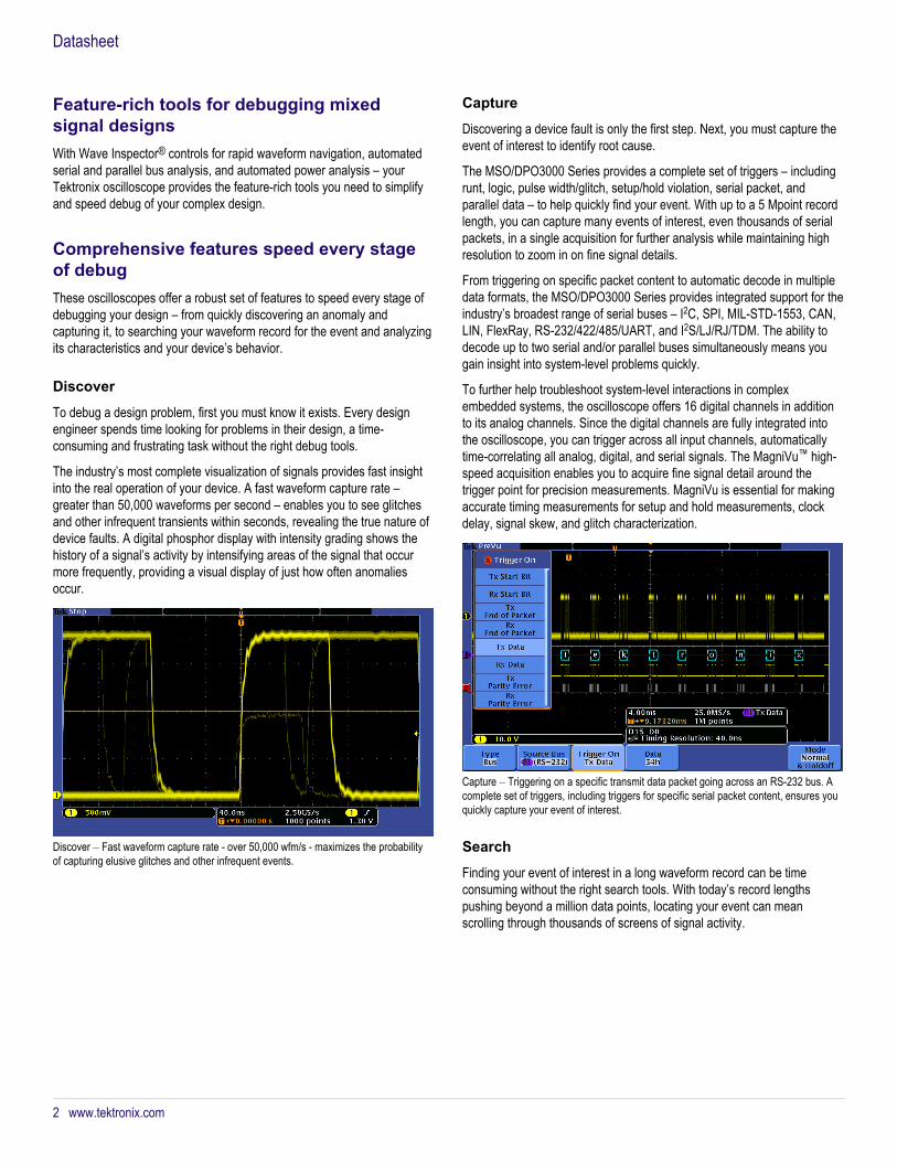
The MSO/DPO3000 Series provides a complete set of triggers – includingrunt, logic, pulse width/glitch, setup/hold violation, serial packet, andparallel data – to help quickly find your event. With up to a 5 Mpoint recordlength, you can capture many events of interest, even thousands of serialpackets, in a single acquisition for further analysis while maintaining highresolution to zoom in on fine signal details.
From triggering on specific packet content to automatic decode in multipledata formats, the MSO/DPO3000 Series provides integrated support for theindustry’s broadest range of serial buses – I2C, SPI, MIL-STD-1553, CAN,LIN, FlexRay, RS-232/422/485/UART, and I2S/LJ/RJ/TDM. The ability todecode up to two serial and/or parallel buses simultaneously means yougain insight into system-level problems quickly.
To further help troubleshoot system-level interactions in complexembedded systems, the oscilloscope offers 16 digital channels in additionto its analog channels. Since the digital channels are fully integrated intothe oscilloscope, you can trigger across all input channels, automaticallytime-correlating all analog, digital, and serial signals. The MagniVu™ high-speed acquisition enables you to acquire fine signal detail around thetrigger point for precision measurements. MagniVu is essential for makingaccurate timing measurements for setup and hold measurements, clockdelay, signal skew, and glitch characterization.
Capture ‒ Triggering on a specific transmit data packet going across an RS-232 bus. Acomplete set of triggers, including triggers for specific serial packet content, ensures youquickly capture your event of interest.
Search
Finding your event of interest in a long waveform record can be timeconsuming without the right search tools. With today’s record lengthspushing beyond a million data points, locating your event can meanscrolling through thousands of screens of signal activity.
Datasheet
2 www.tektronix.com

The innovative Wave Inspector® controls give you the industry’s mostcomprehensive search and waveform navigation capability. These controlsspeed panning and zooming through your record. With a unique force-feedback system, you can move from one end of your record to the other injust seconds. User marks allow you to mark any location that you may wantto reference later for further investigation. Or, automatically search yourrecord for criteria you define. Wave Inspector will instantly search yourentire record, including analog, digital, and serial bus data. Along the way itwill automatically mark every occurrence of your defined event so you canquickly move between events.
Search ‒ I2C decode showing results from a Wave Inspector search for Address value50. Wave Inspector controls provide unprecedented efficiency in viewing and navigatingwaveform data.
Analyze
Verifying that your prototype’s performance matches simulations and meetsthe project’s design goals requires analyzing its behavior. Tasks can rangefrom simple checks of rise times and pulse widths to sophisticated powerloss analysis and investigation of noise sources.
The oscilloscope offers a comprehensive set of integrated analysis toolsincluding waveform- and screen-based cursors, automated measurements,advanced waveform math including arbitrary equation editing, FFTanalysis, and trend plots for visually determining how a measurement ischanging over time. Specialized application support for serial bus analysis,power supply design, and video design and development is also available.
For extended analysis, National Instrument’s LabVIEW SignalExpress®Tektronix Edition provides over 200 built-in functions including time andfrequency domain analysis, limit testing, data logging, and customizablereports.
Analyze ‒ FFT analysis of a pulsed signal. A comprehensive set of integrated analysistools speeds verification of your design's performance.
Wave Inspector® navigation and searchWith long record lengths, a single acquisition can include thousands ofscreens of waveform data. Wave Inspector®, the industry’s best tool fornavigation and search, enables you to find events of interest in seconds.
Wave Inspector controls provide unprecedented efficiency in viewing, navigating, andanalyzing waveform data. Zip through your long record by turning the outer pan control(1). Get details from the beginning to end in seconds. See something of interest and wantto see more details? Just turn the inner zoom control (2).
Zoom and pan
A dedicated, two-tier front-panel control provides intuitive control of bothzooming and panning. The inner control adjusts the zoom factor (or zoomscale); turning it clockwise activates zoom and goes to progressively higherzoom factors, while turning it counterclockwise results in lower zoomfactors and eventually turning zoom off. No longer do you need to navigatethrough multiple menus to adjust your zoom view. The outer control pansthe zoom box across the waveform to quickly get to the portion of waveformyou are interested in. The outer control also utilizes force-feedback todetermine how fast to pan on the waveform. The farther you turn the outercontrol, the faster the zoom box moves. Pan direction is changed by simplyturning the control the other way.
MSO3000 Series and DPO3000 Series Mixed Signal Oscilloscopes
www.tektronix.com 3
Play/Pause
A dedicated Play/Pause front-panel button scrolls the waveform across thedisplay automatically while you look for anomalies or an event of interest.Playback speed and direction are controlled using the intuitive pan control.Once again, turning the control further makes the waveform scroll fasterand changing direction is as simple as turning the control the other way.
User marks
Press the Set Mark front-panel button to place one or more marks on thewaveform. Navigating between marks is as simple as pressing thePrevious (←) and Next (→) buttons on the front panel.
Search marks
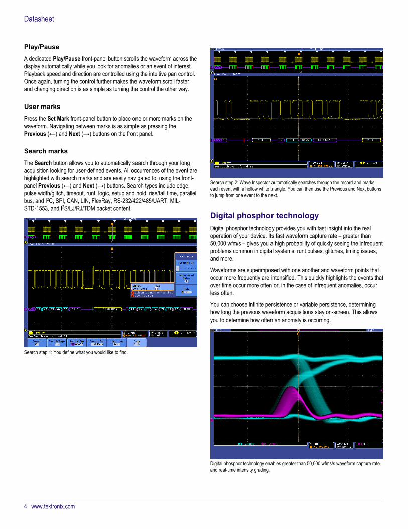
The Search button allows you to automatically search through your longacquisition looking for user-defined events. All occurrences of the event arehighlighted with search marks and are easily navigated to, using the front-panel Previous (←) and Next (→) buttons. Search types include edge,pulse width/glitch, timeout, runt, logic, setup and hold, rise/fall time, parallelbus, and I2C, SPI, CAN, LIN, FlexRay, RS-232/422/485/UART, MIL-STD-1553, and I2S/LJ/RJ/TDM packet content.
Search step 1: You define what you would like to find.
Search step 2: Wave Inspector automatically searches through the record and markseach event with a hollow white triangle. You can then use the Previous and Next buttonsto jump from one event to the next.
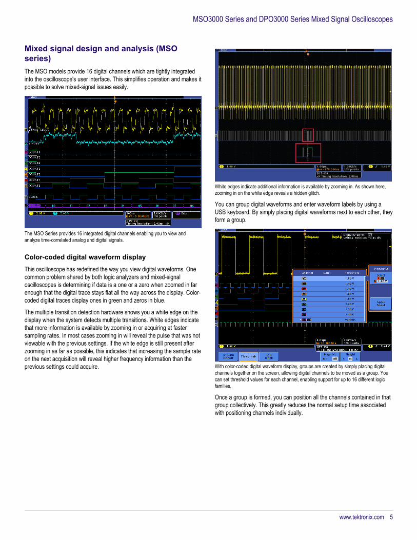
Digital phosphor technologyDigital phosphor technology provides you with fast insight into the realoperation of your device. Its fast waveform capture rate – greater than50,000 wfm/s – gives you a high probability of quickly seeing the infrequentproblems common in digital systems: runt pulses, glitches, timing issues,and more.
Waveforms are superimposed with one another and waveform points thatoccur more frequently are intensified. This quickly highlights the events thatover time occur more often or, in the case of infrequent anomalies, occurless often.
You can choose infinite persistence or variable persistence, determininghow long the previous waveform acquisitions stay on-screen. This allowsyou to determine how often an anomaly is occurring.
Digital phosphor technology enables greater than 50,000 wfms/s waveform capture rateand real-time intensity grading.
Datasheet
4 www.tektronix.com
Mixed signal design and analysis (MSOseries)The MSO models provide 16 digital channels which are tightly integratedinto the oscilloscope's user interface. This simplifies operation and makes itpossible to solve mixed-signal issues easily.
The MSO Series provides 16 integrated digital channels enabling you to view andanalyze time-correlated analog and digital signals.
Color-coded digital waveform display
This oscilloscope has redefined the way you view digital waveforms. Onecommon problem shared by both logic analyzers and mixed-signaloscilloscopes is determining if data is a one or a zero when zoomed in farenough that the digital trace stays flat all the way across the display. Color-coded digital traces display ones in green and zeros in blue.
The multiple transition detection hardware shows you a white edge on thedisplay when the system detects multiple transitions. White edges indicatethat more information is available by zooming in or acquiring at fastersampling rates. In most cases zooming in will reveal the pulse that was notviewable with the previous settings. If the white edge is still present afterzooming in as far as possible, this indicates that increasing the sample rateon the next acquisition will reveal higher frequency information than theprevious settings could acquire.
White edges indicate additional information is available by zooming in. As shown here,zooming in on the white edge reveals a hidden glitch.
You can group digital waveforms and enter waveform labels by using aUSB keyboard. By simply placing digital waveforms next to each other, theyform a group.
With color-coded digital waveform display, groups are created by simply placing digitalchannels together on the screen, allowing digital channels to be moved as a group. Youcan set threshold values for each channel, enabling support for up to 16 different logicfamilies.
Once a group is formed, you can position all the channels contained in thatgroup collectively. This greatly reduces the normal setup time associatedwith positioning channels individually.
MSO3000 Series and DPO3000 Series Mixed Signal Oscilloscopes
www.tektronix.com 5

MagniVu™ high-speed acquisition
The main digital acquisition mode on the MSO3000 Series will capture upto 5 Mpoints at 500 MS/s (2 ns resolution). In addition to the main record,the MSO3000 provides an ultra high-resolution record called MagniVuwhich acquires 10,000 points at up to 8.25 GS/s (121.2 ps resolution). Bothmain and MagniVu waveforms are acquired on every trigger and can beswitched between in the display at any time, running or stopped. MagniVuprovides significantly finer timing resolution than comparable MSOs on themarket, instilling confidence when making critical timing measurements ondigital waveforms.
The MagniVu high-resolution record provides 121.2 ps timing resolution, enabling you totake critical timing measurements on your digital waveforms.
P6316 MSO probe
This unique probe design offers two eight-channel pods, simplifying theprocess of connecting to the device-under-test. When connecting to squarepins, the P6316 can connect directly to 8×2 square pin headers spaced ontenth-inch centers. When more attachment flexibility is required, you canuse the included flying lead sets and grabbers to clip onto surface mountdevices or test points. The P6316 offers outstanding electricalcharacteristics applying only 8 pF of capacitive loading with 101 kΩ inputimpedance.
The P6316 MSO probe offers two eight-channel pods to simplify connecting to yourdevice.
Serial triggering and analysis (optional)On a serial bus, a single signal often includes address, control, data, andclock information. This can make isolating events of interest difficult.Automatic trigger, decode, and search on bus events and conditions givesyou a robust set of tools for debugging serial buses.
Triggering on a specific data packet going across an I2C bus. The yellow waveform isclock and the blue waveform is the data. A bus waveform provides decoded packetcontent including Start, Address, Read/Write, Data, and Stop.
Serial triggering
Trigger on packet content such as start of packet, specific addresses,specific data content, unique identifiers, etc. on popular serial interfacessuch as I2C, SPI, MIL-STD-1553, CAN, LIN, FlexRay, RS-232/422/485/UART, and I2S/LJ/RJ/TDM.
Bus display
Provides a higher-level, combined view of the individual signals (clock,data, chip enable, etc.) that make up your bus, making it easy to identifywhere packets begin and end and identifying sub-packet components suchas address, data, identifier, CRC, etc.
Bus decoding
Tired of having to visually inspect the waveform to count clocks, determineif each bit is a 1 or a 0, combine bits into bytes, and determine the hexvalue? Let the oscilloscope do it for you! Once you’ve set up a bus, theMSO/DPO3000 Series will decode each packet on the bus, and display thevalue in hex, binary, decimal (LIN, FlexRay, and MIL-STD-1553 only),signed decimal (I2S/LJ/RJ/TDM only), or ASCII (MIL-STD-1553 andRS-232/422/485/UART only) in the bus waveform.
Datasheet
6 www.tektronix.com
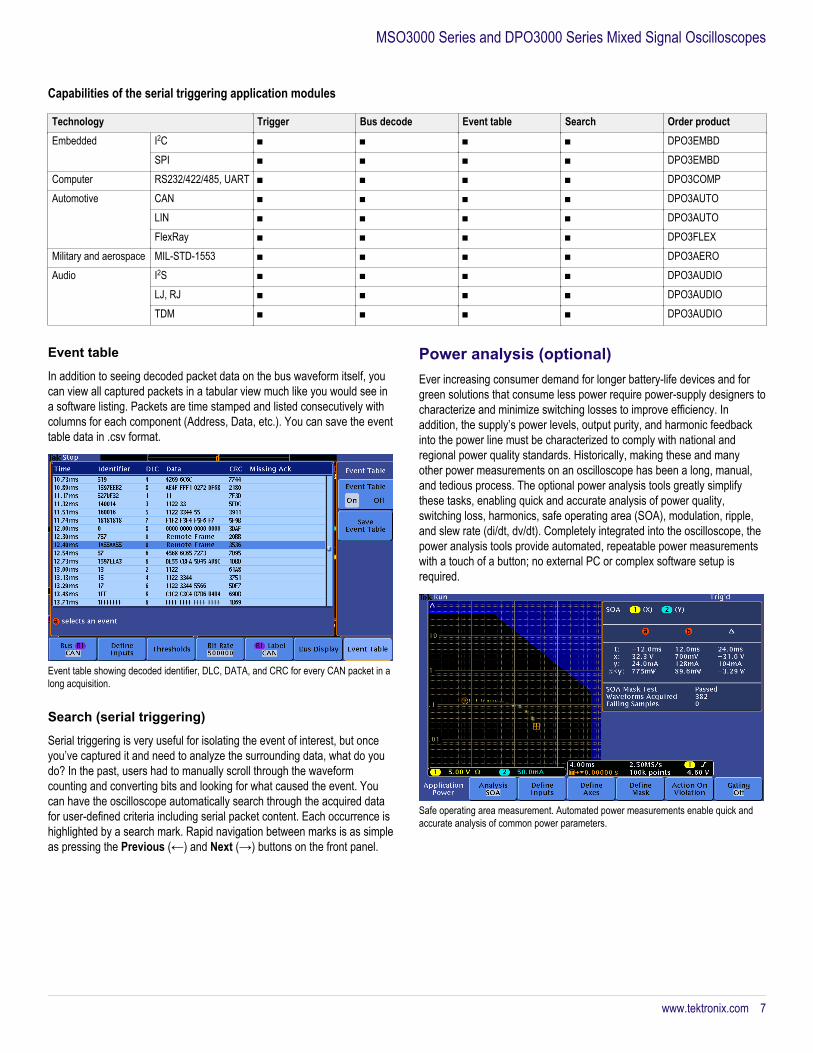
Event table
In addition to seeing decoded packet data on the bus waveform itself, youcan view all captured packets in a tabular view much like you would see ina software listing. Packets are time stamped and listed consecutively withcolumns for each component (Address, Data, etc.). You can save the eventtable data in .csv format.
Event table showing decoded identifier, DLC, DATA, and CRC for every CAN packet in along acquisition.
Search (serial triggering)
Serial triggering is very useful for isolating the event of interest, but onceyou’ve captured it and need to analyze the surrounding data, what do youdo? In the past, users had to manually scroll through the waveformcounting and converting bits and looking for what caused the event. Youcan have the oscilloscope automatically search through the acquired datafor user-defined criteria including serial packet content. Each occurrence ishighlighted by a search mark. Rapid navigation between marks is as simpleas pressing the Previous (←) and Next (→) buttons on the front panel.
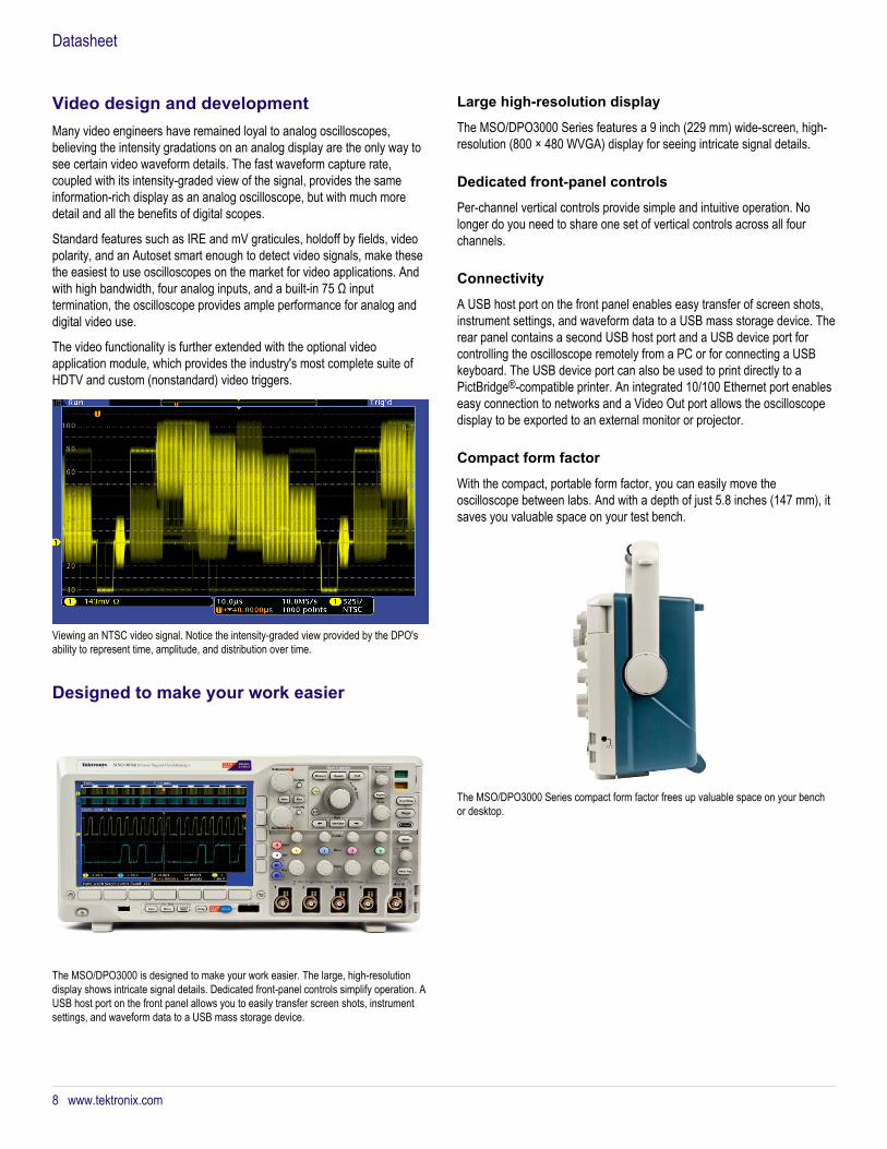
Power analysis (optional)Ever increasing consumer demand for longer battery-life devices and forgreen solutions that consume less power require power-supply designers tocharacterize and minimize switching losses to improve efficiency. Inaddition, the supply’s power levels, output purity, and harmonic feedbackinto the power line must be characterized to comply with national andregional power quality standards. Historically, making these and manyother power measurements on an oscilloscope has been a long, manual,and tedious process. The optional power analysis tools greatly simplifythese tasks, enabling quick and accurate analysis of power quality,switching loss, harmonics, safe operating area (SOA), modulation, ripple,and slew rate (di/dt, dv/dt). Completely integrated into the oscilloscope, thepower analysis tools provide automated, repeatable power measurementswith a touch of a button; no external PC or complex software setup isrequired.
Safe operating area measurement. Automated power measurements enable quick andaccurate analysis of common power parameters.
Capabilities of the serial triggering application modules
Technology Trigger Bus decode Event table Search Order productEmbedded I2C ■ ■ ■ ■ DPO3EMBD
SPI ■ ■ ■ ■ DPO3EMBDComputer RS232/422/485, UART ■ ■ ■ ■ DPO3COMPAutomotive CAN ■ ■ ■ ■ DPO3AUTO
LIN ■ ■ ■ ■ DPO3AUTOFlexRay ■ ■ ■ ■ DPO3FLEX
Military and aerospace MIL-STD-1553 ■ ■ ■ ■ DPO3AEROAudio I2S ■ ■ ■ ■ DPO3AUDIO
LJ, RJ ■ ■ ■ ■ DPO3AUDIOTDM ■ ■ ■ ■ DPO3AUDIO
MSO3000 Series and DPO3000 Series Mixed Signal Oscilloscopes
www.tektronix.com 7
Video design and developmentMany video engineers have remained loyal to analog oscilloscopes,believing the intensity gradations on an analog display are the only way tosee certain video waveform details. The fast waveform capture rate,coupled with its intensity-graded view of the signal, provides the sameinformation-rich display as an analog oscilloscope, but with much moredetail and all the benefits of digital scopes.
Standard features such as IRE and mV graticules, holdoff by fields, videopolarity, and an Autoset smart enough to detect video signals, make thesethe easiest to use oscilloscopes on the market for video applications. Andwith high bandwidth, four analog inputs, and a built-in 75 Ω inputtermination, the oscilloscope provides ample performance for analog anddigital video use.
The video functionality is further extended with the optional videoapplication module, which provides the industry's most complete suite ofHDTV and custom (nonstandard) video triggers.
Viewing an NTSC video signal. Notice the intensity-graded view provided by the DPO'sability to represent time, amplitude, and distribution over time.
Designed to make your work easier
The MSO/DPO3000 is designed to make your work easier. The large, high-resolutiondisplay shows intricate signal details. Dedicated front-panel controls simplify operation. AUSB host port on the front panel allows you to easily transfer screen shots, instrumentsettings, and waveform data to a USB mass storage device.
Large high-resolution display
The MSO/DPO3000 Series features a 9 inch (229 mm) wide-screen, high-resolution (800 × 480 WVGA) display for seeing intricate signal details.
Dedicated front-panel controls
Per-channel vertical controls provide simple and intuitive operation. Nolonger do you need to share one set of vertical controls across all fourchannels.
Connectivity
A USB host port on the front panel enables easy transfer of screen shots,instrument settings, and waveform data to a USB mass storage device. Therear panel contains a second USB host port and a USB device port forcontrolling the oscilloscope remotely from a PC or for connecting a USBkeyboard. The USB device port can also be used to print directly to aPictBridge®-compatible printer. An integrated 10/100 Ethernet port enableseasy connection to networks and a Video Out port allows the oscilloscopedisplay to be exported to an external monitor or projector.
Compact form factor
With the compact, portable form factor, you can easily move theoscilloscope between labs. And with a depth of just 5.8 inches (147 mm), itsaves you valuable space on your test bench.
The MSO/DPO3000 Series compact form factor frees up valuable space on your benchor desktop.
Datasheet
8 www.tektronix.com

TekVPI® probe interface
The TekVPI probe interface sets the standard for ease of use in probing. Inaddition to the secure, reliable connection that the interface provides,TekVPI probes feature status indicators and controls, as well as a probemenu button right on the comp box itself. This button brings up a probemenu on the oscilloscope display with all relevant settings and controls forthe probe. The TekVPI interface enables direct attachment of currentprobes without requiring a separate power supply. TekVPI probes can becontrolled remotely through USB, GPIB, or LAN, enabling more versatilesolutions in ATE environments.
TekVPI probe interface simplifies connecting your probes to the oscilloscope.
Extended analysis
Exporting data and measurements is as simple as connecting a USB cablefrom the oscilloscope to your PC. Key software applications – NI LabVIEWSignalExpress™ Tektronix Edition LE, OpenChoice® Desktop, andMicrosoft Excel and Word toolbars – are included standard with eachoscilloscope to enable fast and easy direct communication with yourWindows PC.
NI LabVIEW SignalExpress Tektronix Edition LE enables you to instantlyacquire, generate, analyze, compare, import, and save measurement dataand signals using an intuitive drag-and-drop user interface that does notrequire any programming. The optional Professional Version offers over200 built-in functions that provide additional signal processing, advancedanalysis, sweeping, limit testing and user-defined step capabilities.
For simple tasks, the included OpenChoice Desktop enables fast and easycommunication between the oscilloscope and your PC through USB or LANfor transferring settings, waveforms, and screen images.
NI LabVIEW SignalExpress™ Tektronix Edition is a fully interactive measurement andanalysis software package developed jointly with National Instruments and optimized forthe MSO/DPO Series.
OpenChoice® Desktop software enables seamless connection between the oscilloscopeand your PC.
MSO3000 Series and DPO3000 Series Mixed Signal Oscilloscopes
www.tektronix.com 9
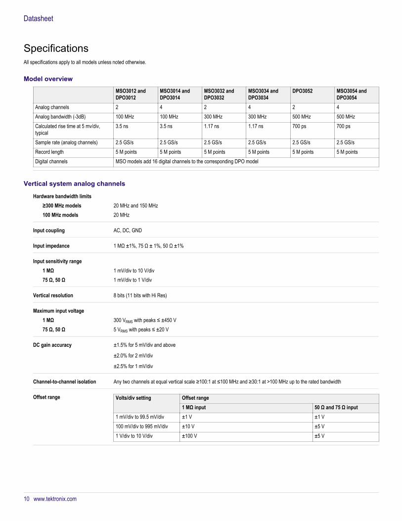
SpecificationsAll specifications apply to all models unless noted otherwise.
Model overview
MSO3012 andDPO3012
MSO3014 andDPO3014
MSO3032 andDPO3032
MSO3034 andDPO3034
DPO3052 MSO3054 andDPO3054
Analog channels 2 4 2 4 2 4 Analog bandwidth (-3dB) 100 MHz 100 MHz 300 MHz 300 MHz 500 MHz 500 MHzCalculated rise time at 5 mv/div,typical
3.5 ns 3.5 ns 1.17 ns 1.17 ns 700 ps 700 ps
Sample rate (analog channels) 2.5 GS/s 2.5 GS/s 2.5 GS/s 2.5 GS/s 2.5 GS/s 2.5 GS/sRecord length 5 M points 5 M points 5 M points 5 M points 5 M points 5 M pointsDigital channels MSO models add 16 digital channels to the corresponding DPO model
Vertical system analog channels
Hardware bandwidth limits≥300 MHz models 20 MHz and 150 MHz100 MHz models 20 MHz
Input coupling AC, DC, GND
Input impedance 1 MΩ ±1%, 75 Ω ± 1%, 50 Ω ±1%
Input sensitivity range1 MΩ 1 mV/div to 10 V/div75 Ω, 50 Ω 1 mV/div to 1 V/div
Vertical resolution 8 bits (11 bits with Hi Res)
Maximum input voltage1 MΩ 300 VRMS with peaks ≤ ±450 V75 Ω, 50 Ω 5 VRMS with peaks ≤ ±20 V
DC gain accuracy ±1.5% for 5 mV/div and above
±2.0% for 2 mV/div
±2.5% for 1 mV/div
Channel-to-channel isolation Any two channels at equal vertical scale ≥100:1 at ≤100 MHz and ≥30:1 at >100 MHz up to the rated bandwidth
Offset range Volts/div setting Offset range1 MΩ input 50 Ω and 75 Ω input
1 mV/div to 99.5 mV/div ±1 V ±1 V100 mV/div to 995 mV/div ±10 V ±5 V1 V/div to 10 V/div ±100 V ±5 V
Datasheet
10 www.tektronix.com

Vertical system digital channels
Thresholds Threshold per set of 8 channels
Threshold selections TTL, CMOS, ECL, PECL, User-defined
User-defined threshold range –15 V to +25 V
Maximum input voltage –20 V to +30 V
Threshold accuracy ±[100 mV + 3% of threshold setting]
Maximum input dynamic range 50 Vp-p (threshold setting dependent)
Minimum voltage swing 500 mVp-p
Input resistance 101 kΩ
Probe loading 8 pF
Vertical resolution 1 bit
Horizontal system analog channels
Maximum duration of timecaptured at highest sample rate(all channels)
2 ms
Seconds/division range 1 ns/div to 1000 s/div
Time-base delay time range -10 divisions to 5000 s
Channel-to-channel deskew range ±100 ns
Time base accuracy ±10 ppm over any ≥1 ms interval
Horizontal system digital channels
Seconds/division range 1 ns/div to 1000 s/div
Maximum record length (main, allchannels)
5 M points
Maximum sample rate (MagniVu,all channels)
8.25 GS/s (121.2 ps resolution)
Maximum record length (MagniVu,all channels)
10 k points centered on the trigger
Minimum detectible pulse width 2.0 ns
Channel-to-channel skew 500 ps, typical, digital channel to digital channel only This is the propagation path skew and ignores skew contributions due tobandpass distortion, threshold inaccuracies (see Threshold accuracy), and sample binning (see Digital channel timing resolution)
MSO3000 Series and DPO3000 Series Mixed Signal Oscilloscopes
www.tektronix.com 11

Trigger system
Trigger modes Auto, Normal, and Single
Trigger coupling DC, AC, HF reject (attenuates >50 kHz), LF reject (attenuates <50 kHz), noise reject (reduces sensitivity)
Trigger holdoff range 20 ns to 8 s
Trigger sensitivity, typical Edge type, DC coupled
Trigger Source SensitivityAny input channel 0.50 div from DC to 50 MHz, increasing to 1 div at oscilloscope
bandwidthAux input (external trigger) 200 mV from DC to 50 MHz, increasing to 500 mV at 250 MHzLine Fixed
Trigger level rangesAny input channel ±8 divisions from center of screen, ±8 divisions from 0 V when vertical LF reject trigger coupling is selectedAux Input (external trigger) ±8 VLine The line trigger level is fixed at about 50% of the line voltage.
Trigger typesEdge Positive or negative slope on any channel or front-panel auxiliary input. Coupling includes DC, AC, HF reject, LF reject, and noise
reject.Sequence (B-trigger) Trigger Delay by Time: 8 ns to 8 s. Or Trigger Delay by Events: 1 to 9,999,999 events.Pulse Width Trigger on width of positive or negative pulses that are >, <, =, ≠, or inside/outside a specified period of time.Timeout Trigger on an event which remains high, low, or either, for a specified time period (4 ns to 8 s).Runt Trigger on a pulse that crosses one threshold but fails to cross a second threshold before crossing the first again.Logic Trigger when any logical pattern of channels goes false or stays true for specified period of time. Any input can be used as a clock
to look for the pattern on a clock edge. Pattern (AND, OR, NAND, NOR) specified for all input channels defined as High, Low, orDon’t Care.
Setup and Hold Trigger on violations of both setup time and hold time between clock and data present on any of the analog and digital inputchannels.
Rise/Fall Time Trigger on pulse edge rates that are faster or slower than specified. Slope may be positive, negative, or either.Video Trigger on all lines, odd, even, or all fields on NTSC, PAL, and SECAM video signals.Extended Video (optional) Trigger on 480p/60, 576p/50, 720p/30, 720p/50, 720p/60, 875i/60, 1080i/50, 1080i/60, 1080p/24, 1080p/24sF, 1080p/25, 1080p/
30, 1080p/50, 1080p/60, and custom bi-level and tri-level sync video standards.I2C (optional) Trigger on Start, Repeated Start, Stop, Missing ACK, Address (7 or 10 bit), Data, or Address and Data on I2C buses up to 10 Mb/s.SPI (optional) Trigger on SS, MOSI, MISO, or MOSI and MISO on SPI buses up to 10.0 Mb/s.RS-232/422/485/UART(optional)
Trigger on Tx Start Bit, Rx Start Bit, Tx End of Packet, Rx End of Packet, Tx Data, Rx Data, Tx Parity Error, and Rx Parity Error upto 10 Mb/s.
CAN (optional) Trigger on Start of Frame, Frame Type (data, remote, error, overload), Identifier (standard or extended), Data, Identifier and Data,End of Frame, Missing ACK, or Bit Stuffing Error on CAN signals up to 1 Mb/s. Data can be further specified to trigger on ≤, <, =,>, ≥, or ≠ a specific data value. User-adjustable sample point is set to 50% by default.
LIN (optional) Trigger on Sync, Identifier, Data, Identifier and Data, Wakeup Frame, Sleep Frame, Errors such as Sync, Parity, or ChecksumErrors up to 100 kb/s (by LIN definition, 20 kb/s).
FlexRay (optional) Trigger on Start of Frame, Type of Frame (Normal, Payload, Null, Sync, Startup), Identifier, Cycle Count, Complete Header Field,Data, Identifier and Data, End of Frame or Errors such as Header CRC, Trailer CRC, Null Frame, Sync Frame, or Startup FrameErrors up to 100 Mb/s.
Datasheet
12 www.tektronix.com

MIL-STD-1553 (optional) Trigger on Sync, Word Type 1 (Command, Status, Data), Command Word (set RT Address, T/R, Sub-address/Mode, Data WordCount/Mode Code, and Parity individually), Status Word (set RT Address, Message Error, Instrumentation, Service Request Bit,Broadcast Command Received, Busy, Subsystem Flag, Dynamic Bus Control Acceptance (DBCA), Terminal Flag, and Parityindividually), Data Word (user-specified 16-bit data value), Error (Sync, Parity, Manchester, Non-contiguous data), Idle Time(minimum time selectable from 2 µs to 100 µs; maximum time selectable from 2 µs to 100 µs; trigger on < minimum, > maximum,inside range, outside range). RT Address can be further specified to trigger on =, ≠, <, >, ≤, ≥ a particular value, or inside oroutside of a range.
I2S/LJ/RJ/TDM (optional) Trigger on Word Select, Frame Sync, or Data. Data can be further specified to trigger on ≤, <, =, >, ≥, ≠ a specific data value, orinside or outside of a range. Maximum data rate for I2S/LJ/RJ is 12.5 Mb/s. Maximum data rate for TDM is 25 Mb/s.
Parallel (available on MSOmodels only)
Trigger on a parallel bus data value. Parallel bus can be from 1 to 16 bits (from the digital channels) plus 2 or 4 bits (from theanalog channels) in size. Binary and Hex radices are supported.
Acquisition system
Acquisition ModesSample Acquire sampled values.Peak Detect Captures glitches as narrow as 2 ns at all sweep speeds.Averaging From 2 to 512 waveforms included in average.Envelope Min-max envelope reflecting Peak Detect data over multiple acquisitions.Hi Res Real-time boxcar averaging reduces random noise and increases vertical resolution.Roll Scrolls waveforms right to left across the screen at sweep speeds slower than or equal to 40 ms/div.
Waveform measurements
Cursors Waveform and Screen.
Automatic measurements 29, of which up to four can be displayed on-screen at any one time. Measurements include: Period, Frequency, Delay, Rise Time,Fall Time, Positive Duty Cycle, Negative Duty Cycle, Positive Pulse Width, Negative Pulse Width, Burst Width, Phase, PositiveOvershoot, Negative Overshoot, Peak to Peak, Amplitude, High, Low, Max, Min, Mean, Cycle Mean, RMS, Cycle RMS, PositivePulse Count, Negative Pulse Count, Rising Edge Count, Falling Edge Count, Area and Cycle Area.
Measurement statistics Mean, Min, Max, Standard Deviation.
Reference levels User-definable reference levels for automatic measurements can be specified in either percent or units.
Gating Isolate the specific occurrence within an acquisition to take measurements on, using either the screen, or waveform cursors.
Power measurements (optional)
Power Quality Measurements VRMS, VCrest Factor, Frequency, IRMS, ICrest Factor, True Power, Apparent Power, Reactive Power, Power Factor, Phase Angle.
Switching loss measurementsPower loss Ton, Toff, Conduction, Total.Energy loss Ton, Toff, Conduction, Total.
Harmonics THD-F, THD-R, RMS measurements. Graphical and table displays of harmonics. Test to IEC61000-3-2 Class A and MIL-STD-1399, Section 300A.
Ripple measurements VRipple and IRipple.
Modulation Analysis Graphical display of +Pulse Width, –Pulse Width, Period, Frequency, +Duty Cycle, and –Duty Cycle modulation types.
1 Trigger selection of Command Word will trigger on Command and ambiguous Command/Status words. Trigger selection of Status Word will trigger on Status and ambiguous Command/Status words.
MSO3000 Series and DPO3000 Series Mixed Signal Oscilloscopes
Trigger system
www.tektronix.com 13
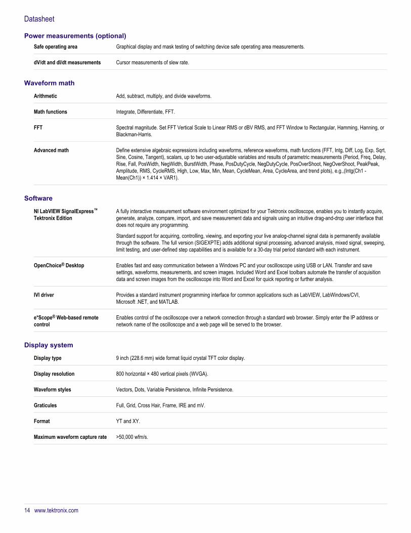
Safe operating area Graphical display and mask testing of switching device safe operating area measurements.
dV/dt and dI/dt measurements Cursor measurements of slew rate.
Waveform math
Arithmetic Add, subtract, multiply, and divide waveforms.
Math functions Integrate, Differentiate, FFT.
FFT Spectral magnitude. Set FFT Vertical Scale to Linear RMS or dBV RMS, and FFT Window to Rectangular, Hamming, Hanning, orBlackman-Harris.
Advanced math Define extensive algebraic expressions including waveforms, reference waveforms, math functions (FFT, Intg, Diff, Log, Exp, Sqrt,Sine, Cosine, Tangent), scalars, up to two user-adjustable variables and results of parametric measurements (Period, Freq, Delay,Rise, Fall, PosWidth, NegWidth, BurstWidth, Phase, PosDutyCycle, NegDutyCycle, PosOverShoot, NegOverShoot, PeakPeak,Amplitude, RMS, CycleRMS, High, Low, Max, Min, Mean, CycleMean, Area, CycleArea, and trend plots), e.g.,(Intg(Ch1 -Mean(Ch1)) × 1.414 × VAR1).
Software
NI LabVIEW SignalExpress™Tektronix Edition
A fully interactive measurement software environment optimized for your Tektronix oscilloscope, enables you to instantly acquire,generate, analyze, compare, import, and save measurement data and signals using an intuitive drag-and-drop user interface thatdoes not require any programming.
Standard support for acquiring, controlling, viewing, and exporting your live analog-channel signal data is permanently availablethrough the software. The full version (SIGEXPTE) adds additional signal processing, advanced analysis, mixed signal, sweeping,limit testing, and user-defined step capabilities and is available for a 30-day trial period standard with each instrument.
OpenChoice® Desktop Enables fast and easy communication between a Windows PC and your oscilloscope using USB or LAN. Transfer and savesettings, waveforms, measurements, and screen images. Included Word and Excel toolbars automate the transfer of acquisitiondata and screen images from the oscilloscope into Word and Excel for quick reporting or further analysis.
IVI driver Provides a standard instrument programming interface for common applications such as LabVIEW, LabWindows/CVI,Microsoft .NET, and MATLAB.
e*Scope® Web-based remotecontrol
Enables control of the oscilloscope over a network connection through a standard web browser. Simply enter the IP address ornetwork name of the oscilloscope and a web page will be served to the browser.
Display system
Display type 9 inch (228.6 mm) wide format liquid crystal TFT color display.
Display resolution 800 horizontal × 480 vertical pixels (WVGA).
Waveform styles Vectors, Dots, Variable Persistence, Infinite Persistence.
Graticules Full, Grid, Cross Hair, Frame, IRE and mV.
Format YT and XY.
Maximum waveform capture rate >50,000 wfm/s.
Datasheet
Power measurements (optional)
14 www.tektronix.com

Input/output ports
USB 2.0 high-speed host port Supports USB mass storage devices, printers, and keyboards. One port available on rear panel and one on front panel.
LAN port (Ethernet) RJ-45 connector, supports 10/100BASE-T.
GPIB interface Available as an optional accessory that connects to the USB Device and USB Host port with the TEK-USB-488 GPIB to USBAdapter. The control interface is incorporated in the instrument user interface.
Video out port DB-15 female connector, connect to show the oscilloscope display on an external monitor or projector. SVGA resolution.
Auxiliary input Front-panel BNC connector. Input Impedance 1 MΩ. Max input 300 VRMS CAT II with peaks ≤ ±425 V.
Probe compensator output voltageand frequency
Front-panel pins
Amplitude 0 to 2.5 VFrequency 1 kHz
Trigger out Rear-panel BNC connector, provides a negative-polarity pulse when the oscilloscope triggers.
Kensington-style lock Rear-panel security slot connects to standard Kensington-style lock.
Power source
Power source voltage 85 to 265 V ±10%
Power source frequency 45 to 440 Hz (85 to 265 V)
Power consumption 120 W maximum
Optional TekVPI® external powersupply 2
Output voltage 12 VOutput current 5 APower consumption 50 W
Physical characteristics
Dimensions mm in.Height 203.2 8 Width 416.6 16.4 Depth 147.3 5.8
Weight kg lb.Net 4.17 9.2 Shipping 8.62 19
Rackmount configuration 5U
Cooling clearance 2 in. (51 mm) required on left side and rear of instrument
2 Required when total oscilloscope probe power usage exceeds 20 W.
MSO3000 Series and DPO3000 Series Mixed Signal Oscilloscopes
www.tektronix.com 15

EMC, environment, and safety
TemperatureOperating 0 ºC to +50 ºC (+32 ºF to 122 ºF)Nonoperating -40 ºC to +71 ºC (-40 ºF to 160 ºF)
HumidityOperating High: 30 ºC to 50 ºC, 5% to 45% relative humidity Low: 0 ºC to 30 ºC, 5% to 95% relative humidityNonoperating High: 30 ºC to 50 ºC, 5%to 45% relative humidity Low: 0 ºC to 30 ºC, 5% to 95% relative humidity
AltitudeOperating 3,000 meters (9,843 feet)Nonoperating 12,000 meters (39,370 feet)
Random vibrationOperating 0.31 GRMS from 5 to 500 Hz, 10 minutes each axis, 3 axes, 30 minutes totalNonoperating 2.46 GRMS from 5 to 500 Hz, 10 minutes each axis, 3 axes, 30 minutes total
RegulatoryElectromagnetic compatibility EC Council Directive 2004/108/ECSafety UL61010-1:2004, CAN/CSA-C22.2 No. 61010.1: 2004, Low Voltage Directive 2006/95/EC and EN61010-1:2001,
IEC 61010-1:2001, ANSI 61010-1-2004, ISA 82.02.01
Ordering information
DPO3000 and MSO3000 modelsDPO3012 100 MHz, 2.5 GS/s, 5 M record length, 2-channel digital phosphor oscilloscope
DPO3014 100 MHz, 2.5 GS/s, 5 M record length, 4-channel digital phosphor oscilloscope
DPO3032 300 MHz, 2.5 GS/s, 5 M record length, 2-channel digital phosphor oscilloscope
DPO3034 300 MHz, 2.5 GS/s, 5 M record length, 4-channel digital phosphor oscilloscope
DPO3052 500 MHz, 2.5 GS/s, 5 M record length, 2-channel digital phosphor oscilloscope
DPO3054 500 MHz, 2.5 GS/s, 5 M record length, 4-channel digital phosphor oscilloscope
MSO3012 100 MHz, 2.5 GS/s, 5 M record length, 2+16 channel mixed-signal oscilloscope
MSO3014 100 MHz, 2.5 GS/s, 5 M record length, 4+16 channel mixed-signal oscilloscope
MSO3032 300 MHz, 2.5 GS/s, 5 M record length, 2+16 channel mixed-signal oscilloscope
MSO3034 300 MHz, 2.5 GS/s, 5 M record length, 4+16 channel mixed-signal oscilloscope
MSO3054 500 MHz, 2.5 GS/s, 5 M record length, 4+16 channel mixed-signal oscilloscope
Datasheet
16 www.tektronix.com
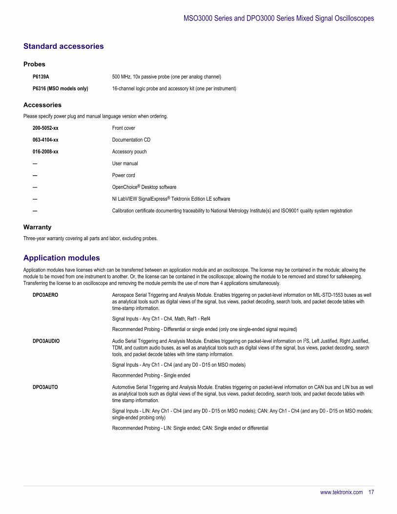
Standard accessories
Probes
P6139A 500 MHz, 10x passive probe (one per analog channel)
P6316 (MSO models only) 16-channel logic probe and accessory kit (one per instrument)
AccessoriesPlease specify power plug and manual language version when ordering.
200-5052-xx Front cover
063-4104-xx Documentation CD
016-2008-xx Accessory pouch
— User manual
— Power cord
— OpenChoice® Desktop software
— NI LabVIEW SignalExpress® Tektronix Edition LE software
— Calibration certificate documenting traceability to National Metrology Institute(s) and ISO9001 quality system registration
WarrantyThree-year warranty covering all parts and labor, excluding probes.
Application modulesApplication modules have licenses which can be transferred between an application module and an oscilloscope. The license may be contained in the module; allowing themodule to be moved from one instrument to another. Or, the license can be contained in the oscilloscope; allowing the module to be removed and stored for safekeeping.Transferring the license to an oscilloscope and removing the module permits the use of more than 4 applications simultaneously.
DPO3AERO Aerospace Serial Triggering and Analysis Module. Enables triggering on packet-level information on MIL-STD-1553 buses as wellas analytical tools such as digital views of the signal, bus views, packet decoding, search tools, and packet decode tables withtime-stamp information.
Signal Inputs - Any Ch1 - Ch4, Math, Ref1 - Ref4
Recommended Probing - Differential or single ended (only one single-ended signal required)
DPO3AUDIO Audio Serial Triggering and Analysis Module. Enables triggering on packet-level information on I2S, Left Justified, Right Justified,TDM, and custom audio buses, as well as analytical tools such as digital views of the signal, bus views, packet decoding, searchtools, and packet decode tables with time stamp information.
Signal Inputs - Any Ch1 - Ch4 (and any D0 - D15 on MSO models)
Recommended Probing - Single ended
DPO3AUTO Automotive Serial Triggering and Analysis Module. Enables triggering on packet-level information on CAN bus and LIN bus as wellas analytical tools such as digital views of the signal, bus views, packet decoding, search tools, and packet decode tables withtime stamp information.
Signal Inputs - LIN: Any Ch1 - Ch4 (and any D0 - D15 on MSO models); CAN: Any Ch1 - Ch4 (and any D0 - D15 on MSO models;single-ended probing only)
Recommended Probing - LIN: Single ended; CAN: Single ended or differential
MSO3000 Series and DPO3000 Series Mixed Signal Oscilloscopes
www.tektronix.com 17
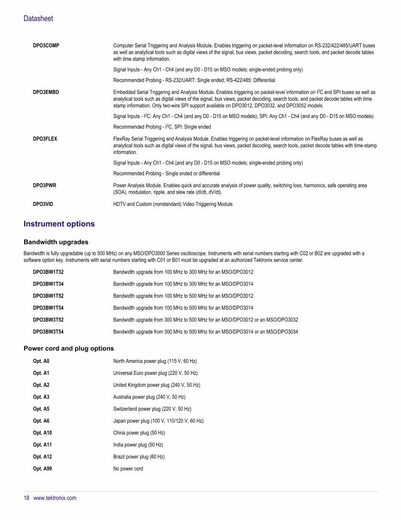
DPO3COMP Computer Serial Triggering and Analysis Module. Enables triggering on packet-level information on RS-232/422/485/UART busesas well as analytical tools such as digital views of the signal, bus views, packet decoding, search tools, and packet decode tableswith time stamp information.
Signal Inputs - Any Ch1 - Ch4 (and any D0 - D15 on MSO models; single-ended probing only)
Recommended Probing - RS-232/UART: Single ended; RS-422/485: Differential
DPO3EMBD Embedded Serial Triggering and Analysis Module. Enables triggering on packet-level information on I2C and SPI buses as well asanalytical tools such as digital views of the signal, bus views, packet decoding, search tools, and packet decode tables with timestamp information. Only two-wire SPI support available on DPO3012, DPO3032, and DPO3052 models.
Signal Inputs - I2C: Any Ch1 - Ch4 (and any D0 - D15 on MSO models); SPI: Any Ch1 - Ch4 (and any D0 - D15 on MSO models)
Recommended Probing - I2C, SPI: Single ended
DPO3FLEX FlexRay Serial Triggering and Analysis Module. Enables triggering on packet-level information on FlexRay buses as well asanalytical tools such as digital views of the signal, bus views, packet decoding, search tools, packet decode tables with time-stampinformation.
Signal Inputs - Any Ch1 - Ch4 (and any D0 - D15 on MSO models; single-ended probing only)
Recommended Probing - Single ended or differential
DPO3PWR Power Analysis Module. Enables quick and accurate analysis of power quality, switching loss, harmonics, safe operating area(SOA), modulation, ripple, and slew rate (dI/dt, dV/dt).
DPO3VID HDTV and Custom (nonstandard) Video Triggering Module.
Instrument options
Bandwidth upgradesBandwidth is fully upgradable (up to 500 MHz) on any MSO/DPO3000 Series oscilloscope. Instruments with serial numbers starting with C02 or B02 are upgraded with asoftware option key. Instruments with serial numbers starting with C01 or B01 must be upgraded at an authorized Tektronix service center.
DPO3BW1T32 Bandwidth upgrade from 100 MHz to 300 MHz for an MSO/DPO3012
DPO3BW1T34 Bandwidth upgrade from 100 MHz to 300 MHz for an MSO/DPO3014
DPO3BW1T52 Bandwidth upgrade from 100 MHz to 500 MHz for an MSO/DPO3012
DPO3BW1T54 Bandwidth upgrade from 100 MHz to 500 MHz for an MSO/DPO3014
DPO3BW3T52 Bandwidth upgrade from 300 MHz to 500 MHz for an MSO/DPO3012 or an MSO/DPO3032
DPO3BW3T54 Bandwidth upgrade from 300 MHz to 500 MHz for an MSO/DPO3014 or an MSO/DPO3034
Power cord and plug options
Opt. A0 North America power plug (115 V, 60 Hz)
Opt. A1 Universal Euro power plug (220 V, 50 Hz)
Opt. A2 United Kingdom power plug (240 V, 50 Hz)
Opt. A3 Australia power plug (240 V, 50 Hz)
Opt. A5 Switzerland power plug (220 V, 50 Hz)
Opt. A6 Japan power plug (100 V, 110/120 V, 60 Hz)
Opt. A10 China power plug (50 Hz)
Opt. A11 India power plug (50 Hz)
Opt. A12 Brazil power plug (60 Hz)
Opt. A99 No power cord
Datasheet
18 www.tektronix.com
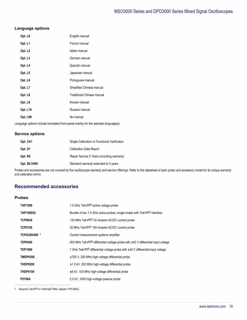
Language options
Opt. L0 English manual
Opt. L1 French manual
Opt. L2 Italian manual
Opt. L3 German manual
Opt. L4 Spanish manual
Opt. L5 Japanese manual
Opt. L6 Portuguese manual
Opt. L7 Simplified Chinese manual
Opt. L8 Traditional Chinese manual
Opt. L9 Korean manual
Opt. L10 Russian manual
Opt. L99 No manual
Language options include translated front-panel overlay for the selected language(s).
Service options
Opt. CA1 Single Calibration or Functional Verification
Opt. D1 Calibration Data Report
Opt. R5 Repair Service 5 Years (including warranty)
Opt. SILV400 Standard warranty extended to 5 years
Probes and accessories are not covered by the oscilloscope warranty and service offerings. Refer to the datasheet of each probe and accessory model for its unique warrantyand calibration terms.
Recommended accessories
Probes
TAP1500 1.5 GHz TekVPI® active voltage probe
TAP1500X2 Bundle of two 1.5 GHz active probes, single ended with TekVPI® interface
TCP0030 120 MHz TekVPI® 30 Ampere AC/DC current probe
TCP0150 20 MHz TekVPI® 150 Ampere AC/DC current probe
TCPA300/400 3 Current measurement systems amplifier
TDP0500 500 MHz TekVPI® differential voltage probe with ±42 V differential input voltage
TDP1000 1 GHz TekVPI® differential voltage probe with ±42 V differential input voltage
TMDP0200 ±750 V, 200 MHz high-voltage differential probe
THDP0200 ±1.5 kV, 200 MHz high-voltage differential probe
THDP0100 ±6 kV, 100 MHz high-voltage differential probe
P5100A 2.5 kV, 100X high-voltage passive probe
3 Requires TekVPI® to TekProbe® BNC adapter (TPA-BNC).
MSO3000 Series and DPO3000 Series Mixed Signal Oscilloscopes
www.tektronix.com 19
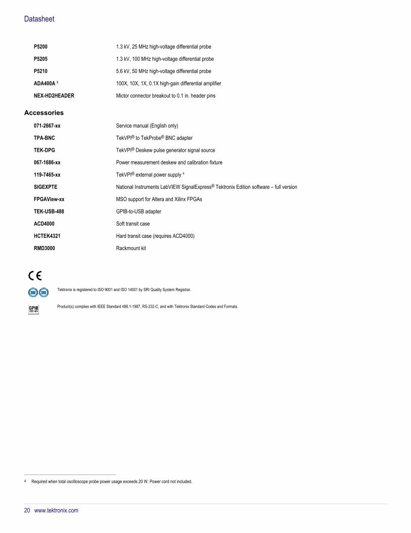
P5200 1.3 kV, 25 MHz high-voltage differential probe
P5205 1.3 kV, 100 MHz high-voltage differential probe
P5210 5.6 kV, 50 MHz high-voltage differential probe
ADA400A 3 100X, 10X, 1X, 0.1X high-gain differential amplifier
NEX-HD2HEADER Mictor connector breakout to 0.1 in. header pins
Accessories
071-2667-xx Service manual (English only)
TPA-BNC TekVPI® to TekProbe® BNC adapter
TEK-DPG TekVPI® Deskew pulse generator signal source
067-1686-xx Power measurement deskew and calibration fixture
119-7465-xx TekVPI® external power supply 4
SIGEXPTE National Instruments LabVIEW SignalExpress® Tektronix Edition software – full version
FPGAView-xx MSO support for Altera and Xilinx FPGAs
TEK-USB-488 GPIB-to-USB adapter
ACD4000 Soft transit case
HCTEK4321 Hard transit case (requires ACD4000)
RMD3000 Rackmount kit
Tektronix is registered to ISO 9001 and ISO 14001 by SRI Quality System Registrar.
Product(s) complies with IEEE Standard 488.1-1987, RS-232-C, and with Tektronix Standard Codes and Formats.
4 Required when total oscilloscope probe power usage exceeds 20 W. Power cord not included.
Datasheet
20 www.tektronix.com

MSO3000 Series and DPO3000 Series Mixed Signal Oscilloscopes
www.tektronix.com 21
Datasheet
ASEAN / Australasia (65) 6356 3900 Austria 00800 2255 4835* Balkans, Israel, South Africa and other ISE Countries +41 52 675 3777 Belgium 00800 2255 4835* Brazil +55 (11) 3759 7627 Canada 1 800 833 9200 Central East Europe and the Baltics +41 52 675 3777 Central Europe & Greece +41 52 675 3777 Denmark +45 80 88 1401 Finland +41 52 675 3777 France 00800 2255 4835* Germany 00800 2255 4835*Hong Kong 400 820 5835 India 000 800 650 1835 Italy 00800 2255 4835*Japan 81 (3) 6714 3010 Luxembourg +41 52 675 3777 Mexico, Central/South America & Caribbean 52 (55) 56 04 50 90 Middle East, Asia, and North Africa +41 52 675 3777 The Netherlands 00800 2255 4835* Norway 800 16098 People's Republic of China 400 820 5835 Poland +41 52 675 3777 Portugal 80 08 12370 Republic of Korea 001 800 8255 2835 Russia & CIS +7 (495) 6647564 South Africa +41 52 675 3777 Spain 00800 2255 4835* Sweden 00800 2255 4835* Switzerland 00800 2255 4835*Taiwan 886 (2) 2722 9622 United Kingdom & Ireland 00800 2255 4835* USA 1 800 833 9200
* European toll-free number. If not accessible, call: +41 52 675 3777 Updated 10 April 2013
For Further Information. Tektronix maintains a comprehensive, constantly expanding collection of application notes, technical briefs and other resources to help engineers working on the cutting edge of technology. Please visit www.tektronix.com.
Copyright © Tektronix, Inc. All rights reserved. Tektronix products are covered by U.S. and foreign patents, issued and pending. Information in this publication supersedes that in all previously published material. Specification and pricechange privileges reserved. TEKTRONIX and TEK are registered trademarks of Tektronix, Inc. All other trade names referenced are the service marks, trademarks, or registered trademarks of their respective companies.
16 Jul 2013 3GW-21364-11
www.tektronix.com