Embed Size (px)
Citation preview
EN Manual
MK2430_D00053_00_M_XXEN/07.2015
Alarm indicator and test combination
Software version: 4.1x
COMTRAXX® MK800

Photos: Bender archives.
Bender GmbH & Co. KGP.O. Box 1161 • 35301 Gruenberg • GermanyLondorfer Straße 65 • 35305 Gruenberg • GermanyTel.: +49 6401 807-0 • Fax: +49 6401 807-259E-mail: [email protected] • www.bender.de
© Bender GmbH & Co. KGAll rights reserved.
Reprinting only with permissionof the publisher.
Subject to change!

Table of Contents
1. How to get the most out of this manual ............................................. 7
1.1 How to use this manual ......................................................................................... 7
1.2 Explanation of symbols and notes .................................................................... 8
2. Safety instructions .................................................................................. 9
2.1 Intended use ............................................................................................................. 9
2.2 Qualified personnel .............................................................................................. 10
2.3 General safety instructions ................................................................................ 11
2.4 Delivery conditions, warranty and liability ................................................... 11
3. System description .............................................................................. 13
3.1 MEDICS® .................................................................................................................... 13
3.2 Characteristics ........................................................................................................ 14
3.3 Functionality ........................................................................................................... 16
3.3.1 Display/operating elements .............................................................................. 16
3.3.2 Programmable messages ................................................................................... 16
3.3.3 History memory ...................................................................................................... 17
3.4 Versions ..................................................................................................................... 17
3.4.1 MK800-12 ................................................................................................................. 17
3.4.2 MK800-11 ................................................................................................................. 17
3.4.3 Interfaces .................................................................................................................. 17
3.4.3.1 Internal BMS bus ............................................................................................ 18
3.4.3.2 External BMS bus ............................................................................................ 18
3.4.3.3 USB interface ................................................................................................... 18
4. Installation and connection ............................................................... 19
4.1 Installation ............................................................................................................... 19
4.1.1 Flush-mounting ..................................................................................................... 19
4.1.2 Cavity wall mounting ........................................................................................... 20
3MK2430_D00053_00_M_XXEN/07.2015
Table of contents
4.1.3 Control panel mounting without enclosure ................................................ 21
4.1.4 Control panel mounting with enclosure ....................................................... 22
4.1.5 Use bezel frame ...................................................................................................... 23
4.1.6 Surface-mounting enclosure ............................................................................. 24
4.2 Connection .............................................................................................................. 26
4.2.1 Connection details ................................................................................................ 27
4.2.2 Wiring diagram ....................................................................................................... 28
4.2.2.1 Connection assignment MK800-12 ......................................................... 30
4.2.2.2 Connection assignment MK800-11 ......................................................... 30
4.2.3 Examples for BMS bus connection and addressing .................................. 31
4.2.4 Address settings and their meaning ............................................................... 35
5. Commissioning and testing ................................................................ 37
5.1 Tests before switching on .................................................................................. 38
5.2 Tests after switching on ...................................................................................... 39
5.3 Make settings (parameterisation) .................................................................... 39
5.3.1 Settings on the MK800 ........................................................................................ 40
5.3.2 Settings using the TMK-SET software ............................................................. 41
5.3.3 Tests after parameter setting ........................................................................... 42
5.4 Periodic verification and service ...................................................................... 43
5.4.1 Periodic verification .............................................................................................. 43
5.4.2 Service and support .............................................................................................. 44
5.4.3 Maintenance ............................................................................................................ 45
6. Troubleshooting ................................................................................... 47
6.1 MK800 error messages ........................................................................................ 47
6.2 Malfunctions ............................................................................................................ 49
7. Operation ............................................................................................... 51
7.1 Operator control and display elements ........................................................ 51
7.2 Quick reference guide .......................................................................................... 53
7.2.1 Display under normal operating conditions ............................................... 53
7.2.2 Display during fault condition .......................................................................... 53
4 MK2430_D00053_00_M_XXEN/07.2015
Table of contents
7.2.3 Test function ........................................................................................................... 55
8. Menu mode: Operation and setting ................................................. 57
8.1 Switching on and calling the main menu ..................................................... 57
8.2 Menu overview diagram ..................................................................................... 59
8.3 Main menu functions ........................................................................................... 60
8.4 The main menu ...................................................................................................... 60
8.4.1 Exit .............................................................................................................................. 60
8.4.2 Menu 2: Measured values ................................................................................... 60
8.4.3 Menu 3: History ...................................................................................................... 61
8.4.4 Menu 4: Settings .................................................................................................... 63
8.4.4.1 Exit ....................................................................................................................... 64
8.4.4.2 Settings menu 2: Alarm addresses .......................................................... 64
8.4.4.3 Settings menu 3: Test addresses .............................................................. 65
8.4.4.4 Settings menu 4: Value addresses ........................................................... 66
8.4.4.5 Settings menu 5: Digital inputs ................................................................ 67
8.4.4.6 Settings menu 6: Buzzer (and LED) .......................................................... 69
8.4.4.7 Settings menu 7: Common reset .............................................................. 69
8.4.4.8 Settings menu 8: Clock ................................................................................ 70
8.4.4.9 Settings menu 9: Language ....................................................................... 71
8.4.4.10 Settings menu 10: Interface ....................................................................... 72
8.4.4.11 Settings menu 11: Relays ............................................................................ 73
8.4.4.12 Settings menu 12: Password ...................................................................... 74
8.4.4.13 Settings menu 13: Service menu .............................................................. 74
8.4.5 Menu 5: Control ...................................................................................................... 75
8.4.5.1 Exit ....................................................................................................................... 75
8.4.5.2 Control menu 2: Reset (AlarmClear) ........................................................ 75
8.4.5.3 Control menu 3: EDS Start/Stop ............................................................... 76
8.4.5.4 Control menu 4: Test communication ................................................... 76
8.4.5.5 Control menu 5: Reset mode ..................................................................... 77
8.4.6 Menu 6: External devices .................................................................................... 77
8.4.7 Menu 7: Info ............................................................................................................. 79
8.5 Overview of setting options .............................................................................. 80
5MK2430_D00053_00_M_XXEN/07.2015
Table of contents
9. Technical data ........................................................................................ 83
9.1 Technical data ......................................................................................................... 83
9.1.1 Standards, approvals and certifications ........................................................ 87
9.2 Ordering information ........................................................................................... 87
6 MK2430_D00053_00_M_XXEN/07.2015

1. How to get the most out of this manual
1.1 How to use this manual This operating manual describes the MK800 alarm indicator and test combination with the software version indicated on the cover page. The functions and processes de-scribed may vary from those featured in other versions. This manual is intended for qualified personnel working in electrical engineering and electronics and in particular for those designing, installing and operating electrical equipment in medical locations.
Chapter "Operation" on page 51 can also be used as a quick reference guide by medical personnel.
Before using the devices, please read this operating manual, the supplement entitled "Important safety instructions for Bender Products" and the instruction leaflets supplied with the individual system components. Keep this document in an easily accessible location near to the devices.
Should you have any questions, please do not hesitate to contact. Please contact our Technical Sales Department. We are also happy to provide on-site service. Please con-tact our Service Department for more information.
Although great care has been taken in the drafting of this operating manual, it may nev-ertheless contain errors and mistakes. Bender cannot accept any liability for injury to persons or damage to property resulting from errors or mistakes in this manual.
7MK2430_D00053_00_M_XXEN/07.2015

How to get the most out of this manual
1.2 Explanation of symbols and notes The following terms and symbols are used to denote hazards and instructions in Bender documentation:
This signal word indicates that there is a high risk of danger that will resultin death or serious injury if not avoided.
This signal word indicates a medium risk of danger that can lead to deathor serious injury if not avoided.
This signal word indicates a low level risk that can result in minor or mod-erate injury or damage to property if not avoided.
This symbol denotes information intended to assist the user in making op-timum use of the product.
DANGER
WARNING
CAUTION
8 MK2430_D00053_00_M_XXEN/07.2015

2. Safety instructions
2.1 Intended useThe universal MK800 alarm indicator and test combination is used for visual and audible indication of operating status and alarm messages from Bender's EDS, RCMS, ATICS® and MEDICS® systems. In MEDICS® monitoring systems, the MK800 meets the requirements of DIN VDE 0100-710 in respect of test functions for IT system monitoring and alarms from transfer switching devices. IT system monitoring equipment can be tested using the program-mable "TEST" button.
Important display functions: Normal operation indicator (green LED) Insulation fault Overload Overtemperature Messages from EDS… insulation fault location systems and RCMS… residual cur-
rent monitoring systems Interruption of the system conductor or PE conductor connection of the
ISOMETER® Supply line failure Power supply fault conditions and transfer switching device faults Device failure Test results Measured values
The clear text display makes information easy to understand. The connection between the MK800 and the changeover and monitoring modules is implemented with bus technology. During normal operation, the MK800 indicates that the system is ready for operation. Version MK800-11 features 16 digital inputs allowing messages from other technical equipment to be recorded and displayed on the MK800, for example from medical gases or battery supported safety power supply systems (BSV systems).
9MK2430_D00053_00_M_XXEN/07.2015

Safety instructions
MK800 are used in: Medical locations Industrial and office buildings Public buildings
Please heed the limits of the application area indicated in the technical specifications. Use which deviates from or is beyond the scope of these technical specifications is con-sidered non-compliant.
Use for intended purpose includes: Device-specific settings compliant with local equipment and operating condi-
tions. The observation of all information in the operating manual. Compliance with test intervals.
2.2 Qualified personnelOnly appropriately qualified personnel may work with the Bender devices. Personnel who are familiar with the installation, commissioning and operation of the equipment and have undergone appropriate training are considered qualified. Personnel must have read this manual and understood all safety-related instructions.
10 MK2430_D00053_00_M_XXEN/07.2015

Safety instructions
2.3 General safety instructionsBender devices are designed and built in accordance with the state of the art and accept-ed rules in respect of technical safety. However, the use of such devices may introduce risks to life and limb of the user or third parties and/or result in damage to Bender equip-ment or other property. Only use Bender devices:
– as intended– In perfect working order– in compliance with the accident prevention regulations and guidelines appli-
cable at the location of use Eliminate all faults immediately which may endanger safety. Do not make any unauthorised changes and only use replacement parts and
optional accessories purchased from or recommended by the manufacturer of the devices. Failure to observe this requirement can result in fire, electric shock and injury.
Reference signs must always be clearly legible. Replace damaged or illegible signs immediately.
Make sure that the dimensions of the BSV (battery-supported safety power sup-ply), the generator set and the whole wiring are adequate. The applicable national and international standards must be observed here. Only in this way selective operation of safety devices can be achieved and a high degree of safety in case of overload and short circuit can be ensured.
2.4 Delivery conditions, warranty and liabilityThe conditions of sale and delivery set out by Bender apply.Conditions of sale and delivery can be obtained from Bender in printed or electronic for-mat.
11MK2430_D00053_00_M_XXEN/07.2015

Safety instructions
12 MK2430_D00053_00_M_XXEN/07.2015

3. System description
3.1 MEDICS®
The MK800 alarm indicator and test combinations are integral components of the MED-ICS® system. MEDICS® is an intelligent system that guarantees safe power supply in medical locations.
Example of a section of a hospital where a MEDICS® system is installed:
13MK2430_D00053_00_M_XXEN/07.2015
System description
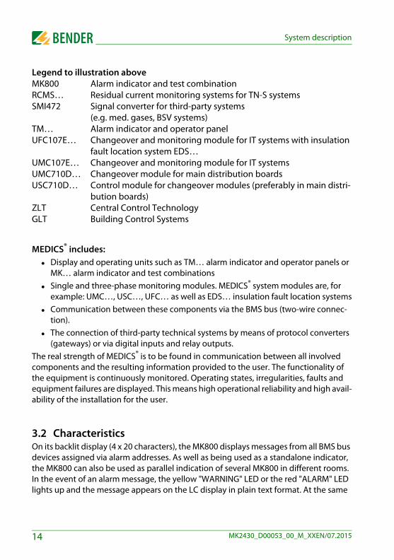
Legend to illustration aboveMK800 Alarm indicator and test combinationRCMS… Residual current monitoring systems for TN-S systemsSMI472 Signal converter for third-party systems
(e.g. med. gases, BSV systems)TM… Alarm indicator and operator panelUFC107E… Changeover and monitoring module for IT systems with insulation
fault location system EDS… UMC107E… Changeover and monitoring module for IT systemsUMC710D… Changeover module for main distribution boardsUSC710D… Control module for changeover modules (preferably in main distri-
bution boards)ZLT Central Control TechnologyGLT Building Control Systems
MEDICS® includes: Display and operating units such as TM… alarm indicator and operator panels or
MK… alarm indicator and test combinations Single and three-phase monitoring modules. MEDICS® system modules are, for
example: UMC…, USC…, UFC… as well as EDS… insulation fault location systems Communication between these components via the BMS bus (two-wire connec-
tion). The connection of third-party technical systems by means of protocol converters
(gateways) or via digital inputs and relay outputs.The real strength of MEDICS® is to be found in communication between all involved components and the resulting information provided to the user. The functionality of the equipment is continuously monitored. Operating states, irregularities, faults and equipment failures are displayed. This means high operational reliability and high avail-ability of the installation for the user.
3.2 CharacteristicsOn its backlit display (4 x 20 characters), the MK800 displays messages from all BMS bus devices assigned via alarm addresses. As well as being used as a standalone indicator, the MK800 can also be used as parallel indication of several MK800 in different rooms.In the event of an alarm message, the yellow "WARNING" LED or the red "ALARM" LED lights up and the message appears on the LC display in plain text format. At the same
14 MK2430_D00053_00_M_XXEN/07.2015
System description
time there is an audible signal (can be acknowledged/muted). If a second message is re-ceived whilst the first is still pending, the audible signal will sound again and the mes-sages will appear alternately on the LC display. In addition, the address of the device triggering the alarm can be called up. The audible signal sounds again once a config-urable period of time has elapsed (repetition can be deactivated).
Internal device parameters (alarm addresses, test addresses…) and also the parameter setting of EDS and RCMS systems can be accessed via the menu system. MK800 can be used as a master device in installations with several IT and EDS systems.The "TEST" button can be used to check the function of the associated devices such as insulation monitoring devices, LIM (Line Isolation Monitors) or GFCI (Ground Fault Cir-cuit interrupters). The message is only available on the MK800 on which the button "TEST" was pressed. The test and its individual evaluations are carried out sequentially. Finally a message appears indicating either a successful test or a fault.
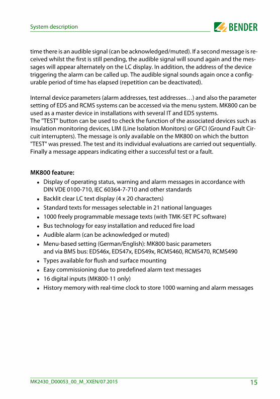
MK800 feature: Display of operating status, warning and alarm messages in accordance with
DIN VDE 0100-710, IEC 60364-7-710 and other standards Backlit clear LC text display (4 x 20 characters) Standard texts for messages selectable in 21 national languages 1000 freely programmable message texts (with TMK-SET PC software) Bus technology for easy installation and reduced fire load Audible alarm (can be acknowledged or muted) Menu-based setting (German/English): MK800 basic parameters
and via BMS bus: EDS46x, EDS47x, EDS49x, RCMS460, RCMS470, RCMS490 Types available for flush and surface mounting Easy commissioning due to predefined alarm text messages 16 digital inputs (MK800-11 only) History memory with real-time clock to store 1000 warning and alarm messages
15MK2430_D00053_00_M_XXEN/07.2015

System description
3.3 Functionality
3.3.1 Display/operating elementsThe backlit display features 4 lines of 20 characters each. It assists medical and technical personnel during the decision-making process with information that is always clear and unambiguous. Every alarm message comprises three lines which appear spontaneously and three additional lines which can be displayed at the touch of a button. The fourth line contains status information (the number of messages, test procedures, menu infor-mation). Below the text display, three LEDs are arranged. They indicate:Normal operation (green), warnings (yellow) or alarms (red). Five buttons are available to acknowledge or to mute alarm and warning messages, for testing the assigned devices and for the menu system.
3.3.2 Programmable messagesStandard message texts can be activated by enabling alarm addresses. These texts are available in 21 national languages. Alarm addresses can be enabled via the device menu system (without personal computer). Individual message texts each comprising 6 lines à 20 characters can be programmed with the TMK-SET PC software. An LED (yellow or red) and an audible signal can be assigned to each message. For this purpose, the PC is connected to the USB interface or BMS bus (RS-485).
************************************ SYSTEM READY ! ***
COMTRAXX©
16 MK2430_D00053_00_M_XXEN/07.2015
System description
3.3.3 History memoryWarnings and alarms are automatically written to the history memory with date and time stamp. 1000 text messages can be stored. Each subsequent message overwrites the oldest message (message 1001 will overwrite message 1 etc.). The history memory can be read out via the operating menu or the TMK-history PC software.
3.4 Versions
3.4.1 MK800-12The MK800-12 is used for visual and audible indication of alarms from Bender EDS, RCMS and MEDICS® systems and for testing assigned devices (insulation monitoring de-vices, LIM, GFCI). Furthermore, the MK800-12 can be used as parallel indication in con-junction with MK800-11 and SMI472-12. The programmed message texts are displayed on the LCD in the selected national language.
3.4.2 MK800-11The MK800-11 features all the functions of the MK800-12. In addition, the MK800-11 provides 16 digital inputs and a programmable relay output.
All digital inputs, divided into four groups of 4, are galvanically isolated from each other. The input voltage is AC/DC 10…30 V/2…5 mA (HIGH = 10…30 V; LOW=0…2 V). In prac-tice, these digital inputs (IN1…IN16) are controlled via an internal or external voltage and potential-free contacts (N/C or N/O operation configurable). The voltage required for these inputs is provided via the power supply unit, which also supplies power to the MK800. Any message text can be assigned to the inputs.
3.4.3 InterfacesMK800 feature an internal BMS bus, an external BMS bus and a USB interface.
17MK2430_D00053_00_M_XXEN/07.2015

System description
3.4.3.1 Internal BMS busThe internal BMS bus is used for communication with BMS bus devices,
– e.g. modules like UMC…, UMA… , UFA…, UFC…, LFC…, ATICS– or devices like RCMS…, EDS…, SMI…, SMO…, alarm indicator and operator
panelsThe MK800 is the master whenever the address is set to 1. An address setting of 2…150 denotes operation as a slave. This setting is only possible when the external BMS bus is disconnected.
The master is responsible for specific tasks: – as a "master clock", it synchronises the time of all devices on the internal BMS
bus;– it controls the data traffic on the BMS bus.
3.4.3.2 External BMS busThe external BMS bus is used as a coupling between alarm indicator and operator pan-els, MK800 and central data recording devices via SMI472-12.The device with address 1 (master) synchronises the time of all devices on the external BMS bus as "master clock". The master function is cyclically passed starting from address 1.
3.4.3.3 USB interfaceA PC can also be connected to the MK800 via the USB interface with a USB cable (Type A plug onto Type B plug).To access the interface, the MK800 has to be removed.
Only the connected MK800 can be read out and set via the USB interface.
Programming and reading the MK800Connect the MK800 to a PC: directly via the USB interface or via an RS-232/RS-485 converter DI-2 or a USB/RS-485 converter DI-2USB to the
internal or external BMS bus.
You can use the optional TMK-SET PC software to display and change the MK800 set-tings. The optional PC software TMK history can be used to read out the MK800.
18 MK2430_D00053_00_M_XXEN/07.2015

4. Installation and connection
4.1 Installation
Overview of enclosure variantsThe MK800 is suitable for flush-mounting as well as for installation in a control panel or cavity wall.The MK800E is only suitable for panel mounting without rear cover.The MK800A and MK800AF in the surface-mounting enclosure are suitable for surface mounting.
4.1.1 Flush-mounting
Dimension diagram flush-mounting enclosure UP800
Fig. 4.1: MK800 in the flush-mounting enclosure. Dimensions in mm.The MK800 is fixed to its enclosure with four screws.
/
19MK2430_D00053_00_M_XXEN/07.2015
Installation and connection
Flush-mounting
1. Insert the cardboard that has been supplied into the flush-mounting enclo-sure to stabilise the enclosure and to provide protection against pollution during mounting.
2. Insert the enclosure so that it is flush with the wall surface. The flush-mount-ing enclosure must not be installed lopsidedly or warped, and must not be installed too deep below the surface.
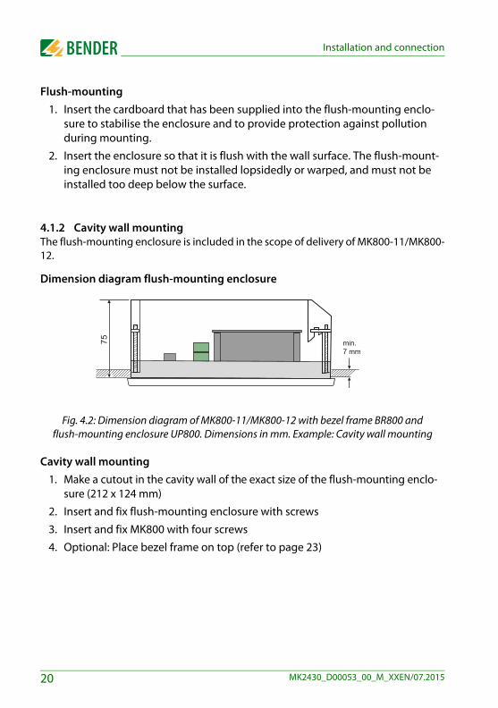
4.1.2 Cavity wall mounting The flush-mounting enclosure is included in the scope of delivery of MK800-11/MK800-12.
Dimension diagram flush-mounting enclosure
Fig. 4.2: Dimension diagram of MK800-11/MK800-12 with bezel frame BR800 and flush-mounting enclosure UP800. Dimensions in mm. Example: Cavity wall mounting
Cavity wall mounting
1. Make a cutout in the cavity wall of the exact size of the flush-mounting enclo-sure (212 x 124 mm)
2. Insert and fix flush-mounting enclosure with screws
3. Insert and fix MK800 with four screws
4. Optional: Place bezel frame on top (refer to page 23)
75 min.7 mm
20 MK2430_D00053_00_M_XXEN/07.2015
Installation and connection
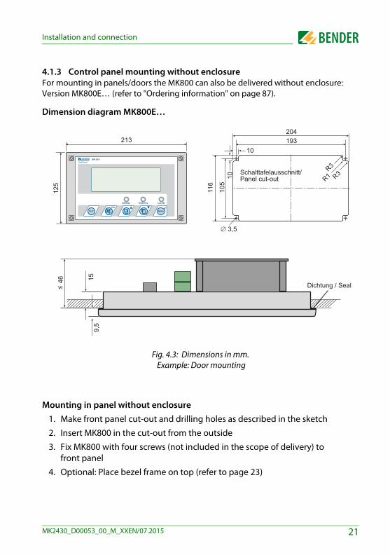
4.1.3 Control panel mounting without enclosure For mounting in panels/doors the MK800 can also be delivered without enclosure: Version MK800E… (refer to "Ordering information" on page 87).
Dimension diagram MK800E…
Fig. 4.3: Dimensions in mm. Example: Door mounting
Mounting in panel without enclosure
1. Make front panel cut-out and drilling holes as described in the sketch
2. Insert MK800 in the cut-out from the outside
3. Fix MK800 with four screws (not included in the scope of delivery) to front panel
4. Optional: Place bezel frame on top (refer to page 23)
COMTRAXX©
125
21MK2430_D00053_00_M_XXEN/07.2015
Installation and connection
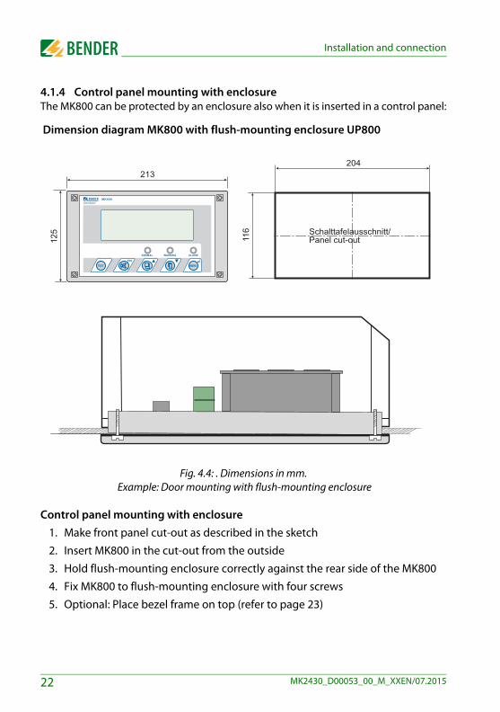
4.1.4 Control panel mounting with enclosure The MK800 can be protected by an enclosure also when it is inserted in a control panel:
Dimension diagram MK800 with flush-mounting enclosure UP800
Fig. 4.4: . Dimensions in mm. Example: Door mounting with flush-mounting enclosure
Control panel mounting with enclosure
1. Make front panel cut-out as described in the sketch
2. Insert MK800 in the cut-out from the outside
3. Hold flush-mounting enclosure correctly against the rear side of the MK800
4. Fix MK800 to flush-mounting enclosure with four screws
5. Optional: Place bezel frame on top (refer to page 23)
COMTRAXX©
125
22 MK2430_D00053_00_M_XXEN/07.2015

Installation and connection
4.1.5 Use bezel frameThe MK800 can optionally be covered with a bezel frame. This frame is not included in the scope of delivery and has to be ordered separately (refer to "Ordering information" on page 87).
Fig. 4.5: Dimension diagram MK800 with bezel frame
After mounting the MK800, the bezel frame is attached to the front of the device.
COMTRAXX©
23MK2430_D00053_00_M_XXEN/07.2015
Installation and connection
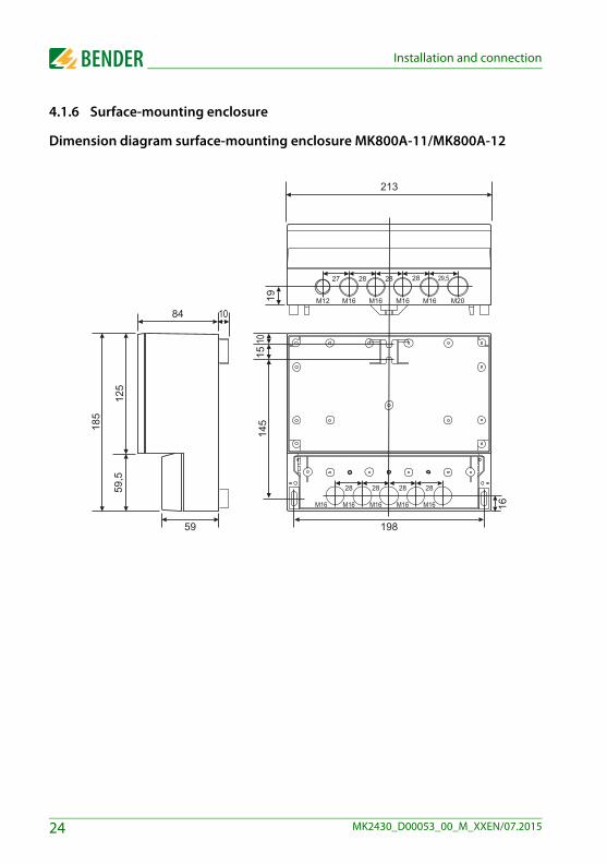
4.1.6 Surface-mounting enclosure
Dimension diagram surface-mounting enclosure MK800A-11/MK800A-12
24 MK2430_D00053_00_M_XXEN/07.2015

Installation and connection
Dimension diagram surface-mounting enclosure with door MK800AF-11/MK800AF-12
Installation of the surface-mounting enclosure
1. Use the empty enclosure as a template for marking the drilling holes. Make the drilling holes in accordance with the material of the subsurface.
2. Fix the empty enclosure with screws. Maximum diameter of the screws: Thread 3 mm, bolt head 7 mm
3. Only in MK800AF: Connect aluminium front panel to the protective conductor (PE).
4. Fix MK800 to the enclosure with screws.
A smooth and even surface is a precondition for installation. Only the fas-tening screws specified below should be used. Failure to observe this canresult in deformation or damage to the enclosure.
25MK2430_D00053_00_M_XXEN/07.2015
Installation and connection
4.2 Connection
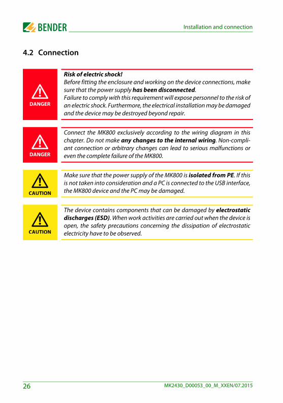
Risk of electric shock!Before fitting the enclosure and working on the device connections, makesure that the power supply has been disconnected.Failure to comply with this requirement will expose personnel to the risk ofan electric shock. Furthermore, the electrical installation may be damagedand the device may be destroyed beyond repair.
Connect the MK800 exclusively according to the wiring diagram in thischapter. Do not make any changes to the internal wiring. Non-compli-ant connection or arbitrary changes can lead to serious malfunctions oreven the complete failure of the MK800.
Make sure that the power supply of the MK800 is isolated from PE. If thisis not taken into consideration and a PC is connected to the USB interface,the MK800 device and the PC may be damaged.
The device contains components that can be damaged by electrostaticdischarges (ESD). When work activities are carried out when the device isopen, the safety precautions concerning the dissipation of electrostaticelectricity have to be observed.
DANGER
DANGER
CAUTION
CAUTION
26 MK2430_D00053_00_M_XXEN/07.2015
Installation and connection
4.2.1 Connection details Connect the MK800 to the supply voltage US (terminals +/-).
– If you are connecting the MK800 to a DC 24 V supply: Take the line voltage drop into account if you are using long supply cables for the supply voltage.
– Consider the maximum permissible cable lengths for the supply voltage US when using an AN450 or AN410 power supply unit (refer to "Technical data").
Connect the internal and external BMS bus according to the instructions in the "BMS bus" leaflet. Use a shielded and twisted cable with a diameter of at least 0.8 mm for the interface line (e.g. J-Y(St)Y n x 2 x 0.8). The shield must be connected to earth at one end. Please note that, when routing the supply voltage Us, a 4-wire cable (2 x BUS, 2 x Us) with suit-able cross section is required.
Use the DIP switches S1 and S2 to set the terminating resistor for the internal and external BMS bus: S1 = external BMS bus; S2 = internal BMS bus. Factory setting S1 and S2: off.
MK800-11 only: Use cables with a cross section of at least 0.75 mm2 when con-necting the digital inputs and the relay output. The maximum cable length per connection is 500 m.
27MK2430_D00053_00_M_XXEN/07.2015

Installation and connection
4.2.2 Wiring diagram
off
on
off
on
off
on
off
on
eAeB
eSiA
iBiS
eA e
B eS
iA i
B iS
exte
rnal
BM
S
inte
rnal
BM
S, g
roup
Ain
tern
al B
MS
, gro
up B
Dig
ital i
nput
s
MK
800-
11 o
nly
DI-1
DL
Bus
2
Bus
2
inte
rner
Bus
absc
hluß
Bus
1
P2
P1
5V
off
onO
N 12
34
Bus
2
B/N
A/P
Bus
15V
B/N
N
Pow
er
L
A/P
Bus
1
19
25
43
76
8
28 MK2430_D00053_00_M_XXEN/07.2015
Installation and connection
Legend to wiring diagram
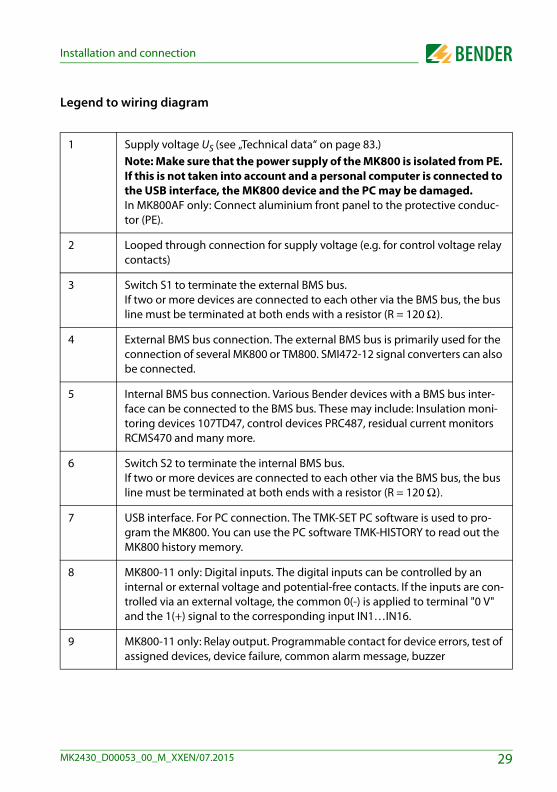
1 Supply voltage US (see „Technical data“ on page 83.)Note: Make sure that the power supply of the MK800 is isolated from PE. If this is not taken into account and a personal computer is connected to the USB interface, the MK800 device and the PC may be damaged. In MK800AF only: Connect aluminium front panel to the protective conduc-tor (PE).
2 Looped through connection for supply voltage (e.g. for control voltage relay contacts)
3 Switch S1 to terminate the external BMS bus. If two or more devices are connected to each other via the BMS bus, the bus line must be terminated at both ends with a resistor (R = 120 Ω).
4 External BMS bus connection. The external BMS bus is primarily used for the connection of several MK800 or TM800. SMI472-12 signal converters can also be connected.
5 Internal BMS bus connection. Various Bender devices with a BMS bus inter-face can be connected to the BMS bus. These may include: Insulation moni-toring devices 107TD47, control devices PRC487, residual current monitors RCMS470 and many more.
6 Switch S2 to terminate the internal BMS bus. If two or more devices are connected to each other via the BMS bus, the bus line must be terminated at both ends with a resistor (R = 120 Ω).
7 USB interface. For PC connection. The TMK-SET PC software is used to pro-gram the MK800. You can use the PC software TMK-HISTORY to read out the MK800 history memory.
8 MK800-11 only: Digital inputs. The digital inputs can be controlled by an internal or external voltage and potential-free contacts. If the inputs are con-trolled via an external voltage, the common 0(-) is applied to terminal "0 V" and the 1(+) signal to the corresponding input IN1…IN16.
9 MK800-11 only: Relay output. Programmable contact for device errors, test of assigned devices, device failure, common alarm message, buzzer
29MK2430_D00053_00_M_XXEN/07.2015

Installation and connection
4.2.2.1 Connection assignment MK800-12The MK800-12 edition receives all messages from the BMS bus. These messages can be received, for example, from an 107TD47, an MK800-11, a signal converter SMI47x, an EDS… or a RCMS….
4.2.2.2 Connection assignment MK800-11The MK800-11 alarm indicator and test combination provides additional terminal strips for the 16 digital inputs and one optional relay output.
US Supply voltage US: looped through connection for supply voltage US. Note: Make sure that the power supply of the MK800 is isolated from PE. If this is not taken into consideration and if a personal computer is connected to the USB interface, the MK800 device and the PC may be damaged.
eA, eB, eS External BMS bus with shield S
iA, iB, iS Internal BMS bus with shield S
USB USB connection. Cable: type A plug on type B plug.
S1, S2 Switch S1 to terminate the external BMS bus and switch S2 to terminate the internal BMS bus.
IN1…IN16 Digital inputs 1…16
0 V (IN1…4) Common connection "0" for digital inputs 1…4
0 V (IN5…8) Common connection "0" for digital inputs 5…8
0 V (IN9…12) Common connection "0" for digital inputs 9…12
0 V (IN12…16) Common connection "0" for digital inputs 12…16
11, 12, 14 Relay output
30 MK2430_D00053_00_M_XXEN/07.2015
Installation and connection
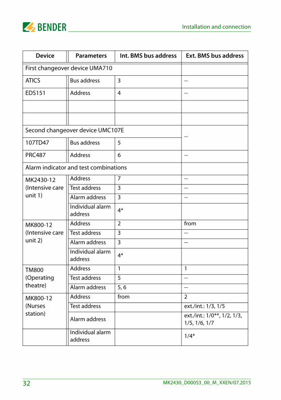
4.2.3 Examples for BMS bus connection and addressing
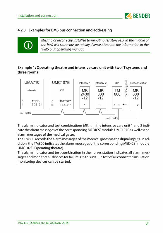
Example 1: Operating theatre and intensive care unit with two IT systems and three rooms
The alarm indicator and test combinations MK… in the intensive care unit 1 and 2 indi-cate the alarm messages of the corresponding MEDICS® module UMC107E as well as the alarm messages of the medical gases. The TM800 records the alarm messages of the medical gases via the digital inputs. In ad-dition, the TM800 indicates the alarm messages of the corresponding MEDICS® module UMC107E (Operating theatre). The alarm indicator and test combination in the nurses station indicates all alarm mes-sages and monitors all devices for failure. On this MK… a test of all connected insulation monitoring devices can be started.
Missing or incorrectly installed terminating resistors (e.g. in the middle ofthe bus) will cause bus instability. Please also note the information in the"BMS bus" operating manual.
UMA710
3 ATICS4 EDS151
31MK2430_D00053_00_M_XXEN/07.2015
Installation and connection
Device Parameters Int. BMS bus address Ext. BMS bus address
First changeover device UMA710
ATICS Bus address 3 --
EDS151 Address 4 --
Second changeover device UMC107E--
107TD47 Bus address 5
PRC487 Address 6 --
Alarm indicator and test combinations
MK2430-12(Intensive care unit 1)
Address 7 --
Test address 3 --
Alarm address 3 --
Individual alarm address
4*
MK800-12 (Intensive care unit 2)
Address 2 from
Test address 3 --
Alarm address 3 --
Individual alarm address
4*
TM800(Operating theatre)
Address 1 1
Test address 5 --
Alarm address 5, 6 --
MK800-12(Nurses station)
Address from 2
Test address ext./int.: 1/3, 1/5
Alarm addressext./int.: 1/0**, 1/2, 1/3, 1/5, 1/6, 1/7
Individual alarm address
1/4*
32 MK2430_D00053_00_M_XXEN/07.2015

Installation and connection
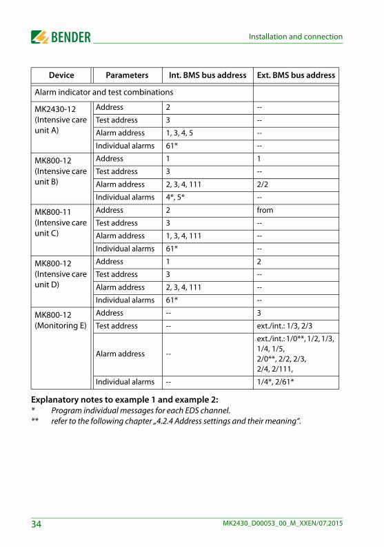
Example 2: Intensive care area with two IT systems and four rooms
The alarm indicator and test combinations MK… in the intensive care units A and B or C and D indicate all alarm messages of the corresponding MEDICS® module UMA710 or UFC107E. On this MK… a test of all corresponding insulation monitoring devices can be started. The MK800-11 (C) records the alarm messages of the medical gases via the digital in-puts. The MKs B, C, D and E indicate the alarm messages of the medical gases. The MK800-12 (E) allows monitoring of the entire installation. It indicates all alarm mes-sages and monitors all devices for failure. On this MK… a test of all connected insulation monitoring devices can be started.
Device Parameters Int. BMS bus address Ext. BMS bus address
Changeover and monitoring module UFA710 (Intensive care unit A, B)
ATICS Bus address 3 --
EDS151 Address 4 --
EDS151 Address 5 --
Changeover and monitoring module UFC107E (Intensive care unit C, D)
107TD47 Bus address 3 --
PRC487 Address 4 --
PGH474 Address 111 --
EDS474-12 Address 61 --
UFA710
Intensiv A, B
3 ATICS4 EDS1515 EDS151
int. BMS int. BMS
ext. BMS
med
ical
gas
es
33MK2430_D00053_00_M_XXEN/07.2015
Installation and connection
Explanatory notes to example 1 and example 2:* Program individual messages for each EDS channel. ** refer to the following chapter „4.2.4 Address settings and their meaning“.
Alarm indicator and test combinations
MK2430-12(Intensive care unit A)
Address 2 --
Test address 3 --
Alarm address 1, 3, 4, 5 --
Individual alarms 61* --
MK800-12(Intensive care unit B)
Address 1 1
Test address 3 --
Alarm address 2, 3, 4, 111 2/2
Individual alarms 4*, 5* --
MK800-11(Intensive care unit C)
Address 2 from
Test address 3 --
Alarm address 1, 3, 4, 111 --
Individual alarms 61* --
MK800-12 (Intensive care unit D)
Address 1 2
Test address 3 --
Alarm address 2, 3, 4, 111 --
Individual alarms 61* --
MK800-12(Monitoring E)
Address -- 3
Test address -- ext./int.: 1/3, 2/3
Alarm address --
ext./int.: 1/0**, 1/2, 1/3, 1/4, 1/5, 2/0**, 2/2, 2/3, 2/4, 2/111,
Individual alarms -- 1/4*, 2/61*
Device Parameters Int. BMS bus address Ext. BMS bus address
34 MK2430_D00053_00_M_XXEN/07.2015
Installation and connection
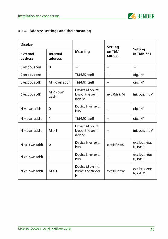
4.2.4 Address settings and their meaning
Display
MeaningSettingon TM/MK800
Settingin TMK-SETExternal
addressInternal address
0 (ext bus on) 0 -- -- --
0 (ext bus on) 1 TM/MK itself -- dig. IN*
0 (ext bus off ) M = own addr. TM/MK itself -- dig. IN*
0 (ext bus off )M <> own addr.
Device M on int. bus of the own device
ext: 0/int: M int. bus: int M
N = own addr. 0Device N on ext. bus
-- dig. IN*
N = own addr. 1 TM/MK itself -- dig. IN*
N = own addr. M > 1Device M on int. bus of the own device
-- int. bus: int M
N <> own addr. 0Device N on ext. bus
ext: N/int: 0ext. bus: ext: N, int: 0
N <> own addr. 1Device N on ext. bus
--ext. bus: ext: N, int: 0
N <> own addr. M > 1Device M on int. bus of the device N
ext: N/int: Mext. bus: ext: N, int: M
35MK2430_D00053_00_M_XXEN/07.2015
Installation and connection
Explanatory notes to digital inputs (only MK800-11)Alarm messages from digital inputs on TM/MK800 are always displayed on the device itselfregardless of whether an individual message has been programmed or not (exception: thechannel is deactivated). An entry into the alarm address table is not required. - If no individual message is programmed, the standard text will be displayed. - An alarm message can also be programmed to be displayed without text/LED/buzzer (si-
lent message). - Note: Flashing alarm messages are not allowed!
In principle, all alarm messages are stored in the history memory (Exception: channel is de-activated): - If no individual message is programmed, the standard text will be displayed or stored in
the history memory. - If the message has been programmed without a text (silent message), its source (DigIn or
address and channel no.) will be stored in the history memory (no individual text possi-ble!).
- TEST messages are only stored in the history memory of the device that triggered the mes-sage.
Transmission via BMS bus: All alarm messages are actively sent (i.e. as a new message) via the external or internal BMS.
Operating messages are actively sent via the external BMS bus and are not stored in thehistory memory. - Note: Flashing messages must be avoided where possible, and on no account be sig-
nalled via the int./ext. BMS bus! - The first 16 digital inputs can be configured as "flashing" and in this case are not signalled
via the external BMS. This is only permissible for messages with a flashing frequency of0.5 Hz!
Inputs that are assigned to operating messages or switching commands are not displayedwith a text message or stored in the history memory.
36 MK2430_D00053_00_M_XXEN/07.2015
5. Commissioning and testing
Start commissioning according to the following commissioning pattern:
1. Tests before switching on
2. Tests after switching on
3. Set parameters (parameterisation) – Settings at the MK800– Settings in the TMK-SET software
4. Tests after parameter setting
Write down all settings and keep it together with the device and installa-tion documentation.When setting the MK800 with the configuration software TMK-SET, aproject file is created. Save this file. Create a backup copy of this file andkeep it in a safe place.
37MK2430_D00053_00_M_XXEN/07.2015

Commissioning and testing
5.1 Tests before switching on
Continue with chapter „5.2 Tests after switching on“
������������ ����������� ��������� ��������
� ��������������� ������������������ ����� �� �������������������
���������������������� ������������� �������������������������������� ����� �!������������������ �����"���� ���� ���������� ���������� ������������
� #� ������������� ������ ���������� �����"
��$���������� ������� ������ �
�������%���"&�'�"(� �!����� ��������� ��������
� ��$���������� ������� ������ ����������$
� ������� �����������������& )
�������&� ��������������������������� ��� ��������%����������#�������*+���*�������,
�-./�,�+�"""(
���
���
���
���011� ���2�������� �������� ��������������������
� ������
��$��� ������ ��
���
���011� ���2������������������������ �������
� ��������
��$��� ������ ��
���
�������� ������������� ��������� ��������
��$��� ������ ��
���
���
������������������� ����� �!��������� �� �������������� ������
��������������������������
��$��� ������ ��,����������$����������������� ������������������ �"
���
3��������������4��������� ������* �!����*
��������� �������������������
��$��� ������ ��
���
��������������������������������� ������
5������ �����������"
���
!������� ������������� �"+������ ����������*��������������������� �*"*
�
�
�
�
�
�
�
�
38 MK2430_D00053_00_M_XXEN/07.2015

Commissioning and testing
5.2 Tests after switching on
Continue with chapter „5.3 Make settings (parameterisation)“
5.3 Make settings (parameterisation)
All settings can be carried out via the TMK-SET software. Alternatively,some settings can be carried out via the MK800 menu (see diagrams).
6���$���������������� ������%����������0"7("
8 ������9����5���� �������� ��#:�
� ��$��� ������ ��"�����4�����,�� �������� ���� ������������� ���������������� ������������"
!������� �������������� �������������0�;�����
���������"
���
������������������� �������� ����"
� ��������� ���������������� ���������
��������
��$����� ��� ������������"����������������������������� ����
������� ������������������"
� �������������������� �����������������
�
������
6 ��������#6������������+�!���� ������"�!���������+�!���*!�������*������ �"�6���$�����������0��������� ������������ �� ������� ����������������
� ��$��� ������ ��
���
!�����������������
�
39MK2430_D00053_00_M_XXEN/07.2015

Commissioning and testing
5.3.1 Settings on the MK800For details refer to "Menu 4: Settings" on page 63.
Continue with chapter „5.3.3 Tests after parameter setting“
!�����������
!���%���"&�'�"(� �!�������������
!������������������������������������
!��������������������������� ���� ������
���011� 5��� �������������������������� ���������
�����&5#!�
6���������<<���� ����������������������� ���������
�� �������������
6 �� ���$� ����������� �& ��
���
!�������&����
5��� �������������'��� 5���+�0!:+�8/"'�� �������������������%� ���������������� �="/"-(
�
!�������*�������*,>���������"�� ������������ ��)
;����2�!��������� ��������������������� ��"
�
� �������<<�����������
!��������������������� ��
�
���
�
40 MK2430_D00053_00_M_XXEN/07.2015

Commissioning and testing
5.3.2 Settings using the TMK-SET software
Continue with chapter „5.3.3 Tests after parameter setting“
!�����������
!�������� ��
!�����<<��
6 �� ���$� ����������� �& ��
���011�
��������������2�!��������� ����� ������������������"
;����2�!��������� ����� ������������������"
!�����������������"
!���������������2�:����������4��������'�"
#� ��������������������� ����������������
��������"
:�������������������� ����������������� ��"
���
���
:������������������������������� ��������4�����
��������"�������������,���������0��� ������� ��"
:�������������������"
!����������������������� ����"
!������������������� ��"
!������������������������ ��"
������������ ������������ ������������������"
���
5��� ���������������������� ���������������&5#!�
!�������*�������*,>���������"�� ������������ ��)
���
�
41MK2430_D00053_00_M_XXEN/07.2015

Commissioning and testing
5.3.3 Tests after parameter setting
(*) Messages which can be created by a BMS device are simulated.
!������*+����� ��*��� ����������*:'��������������*"���������'�������������
���������9�
� ��$��� ������ ��
!����������������������%�"�"���������������,
�������� �������("�?������������������������ ������������*+����� ��������� �*������ �"�������������
� ����������������������������
���
�
���
�������������� � ������ �"
��$��� ������ ��� ������������������ ������� ���������������
���������������
� ��$��� ������ ��
42 MK2430_D00053_00_M_XXEN/07.2015

Commissioning and testing
5.4 Periodic verification and service
5.4.1 Periodic verificationThe following periodic verification must be performed on electrical installations in com-pliance with the local or national regulations that apply. For your Bender products, we recommend:
* This test must only be performed by an authorised electrically skilled person in agree-ment with the medical locations concerned.
Task By Interval
Functional test of IT system monitoring (insulation, load current, transformer temperature and connection moni-toring) by pressing the "TEST" button on the alarm indicator and test com-bination or on the alarm indicator and operator panel.
Medical personnel
Once every working day
Functional test of the transfer switching device*: Functional test of the automatic transfer switching devices. Follow the instructions in chapter "Testing of the transfer switching device"!
Electri-cally skilled person
Once every six months
Functional test of the IT system monitoring (insulation, load current, trans-former temperature and connection monitoring) on the insulation moni-toring device.
Electri-cally skilled person
Once every six months
Checking the setting values and the changeover periods
Electri-cally skilled person
Once every 12 months
Test of the transfer switching device, the IT system monitoring, and the connection to the SCADA system (Supervisory Control and Data Acquisi-tion) (if applicable) and the interaction between the components in the system.
The test includes the following:
- Inspection: Marking, display elements, mechanical components, wiring, parameterisation, connection of third-party systems, evaluation of fault memory
- Measurement: Internal/external supply voltages/potentials, bus volt-age, bus protocol, bus scan
- Testing: Device function, device communication - Documentation: Test results, recommendations for elimination of
defects
Bender service
Once every 24 months
43MK2430_D00053_00_M_XXEN/07.2015

Commissioning and testing
Before carrying out the tests, please refer to the instructions relating to the functional tests in the check list. If no national directives apply, you should perform the tests recom-mended by DIN VDE 0100-710 (VDE 0100-710).
5.4.2 Service and supportFor commissioning, troubleshooting and periodic verificationBender offers:
First Level SupportTechnical support by phone or e-mail for all Bender products Questions regarding specific customer applications Commissioning Troubleshooting
Telephone: +49 6401 807-760*Fax: +49 6401 807-259In Germany only: 0700BenderHelp (Telephone and Fax)E-mail: [email protected]
Repair serviceRepair, calibration, update and replacement service for all Bender products Repair, calibration, testing and analysing of Bender products Hardware and software update for Bender devices Delivery of replacement devices for faulty or incorrectly delivered Bender devices Extended warranty for Bender devices with in-house repair service or replace-
ment device at no extra cost
Telephone: +49 6401 807-780** (technical issues)+49 6401 807-784**, -785** (commercial issues)
Fax: +49 6401 807-789E-mail: [email protected]
Please send the devices for repair to the following address:Bender GmbH, Repair-Service, Londorfer Straße 65, 35305 Grünberg
44 MK2430_D00053_00_M_XXEN/07.2015

Commissioning and testing
Field ServiceOn-site service for all Bender products Commissioning, parameter setting, maintenance, troubleshooting for Bender
products Analysis of the electrical installation in the building (power quality test, EMC test,
thermography) Practical training courses for customers
Telephone: +49 6401 807-752**, -762 **(technical issues)+49 6401 807-753** (commercial issues)
Fax: +49 6401 807-759E-mail: [email protected]
*Available from 7.00 a.m. to 8.00 p.m. 365 days a year (CET/UTC+1)**Mo-Thu 7.00 a.m. - 8.00 p.m., Fr 7.00 a.m. - 13.00 p.m.
Internet: www.bender.de
5.4.3 MaintenanceMK800 does not contain any parts that require maintenance. Despite this, the intervals specified for periodic verification should be adhered to.
45MK2430_D00053_00_M_XXEN/07.2015

Commissioning and testing
46 MK2430_D00053_00_M_XXEN/07.2015
6. Troubleshooting
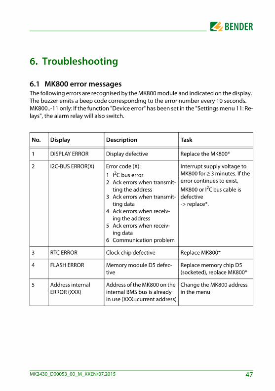
6.1 MK800 error messagesThe following errors are recognised by the MK800 module and indicated on the display. The buzzer emits a beep code corresponding to the error number every 10 seconds. MK800..-11 only: If the function "Device error" has been set in the "Settings menu 11: Re-lays", the alarm relay will also switch.
No. Display Description Task
1 DISPLAY ERROR Display defective Replace the MK800*
2 I2C-BUS ERROR(X) Error code (X):1 I2C bus error2 Ack errors when transmit-
ting the address3 Ack errors when transmit-
ting data4 Ack errors when receiv-
ing the address5 Ack errors when receiv-
ing data6 Communication problem
Interrupt supply voltage to MK800 for ≥ 3 minutes. If the error continues to exist, MK800 or I2C bus cable is defective -> replace*.
3 RTC ERROR Clock chip defective Replace MK800*
4 FLASH ERROR Memory module D5 defec-tive
Replace memory chip D5 (socketed), replace MK800*
5 Address internal ERROR (XXX)
Address of the MK800 on the internal BMS bus is already in use (XXX=current address)
Change the MK800 address in the menu
47MK2430_D00053_00_M_XXEN/07.2015
Troubleshooting
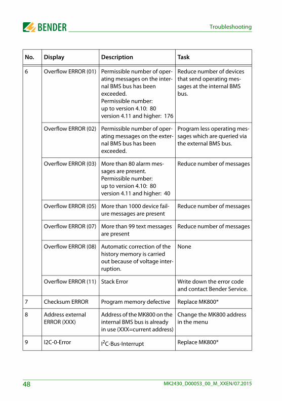
6 Overflow ERROR (01) Permissible number of oper-ating messages on the inter-nal BMS bus has been exceeded. Permissible number:up to version 4.10: 80version 4.11 and higher: 176
Reduce number of devices that send operating mes-sages at the internal BMS bus.
Overflow ERROR (02) Permissible number of oper-ating messages on the exter-nal BMS bus has been exceeded.
Program less operating mes-sages which are queried via the external BMS bus.
Overflow ERROR (03) More than 80 alarm mes-sages are present. Permissible number:up to version 4.10: 80version 4.11 and higher: 40
Reduce number of messages
Overflow ERROR (05) More than 1000 device fail-ure messages are present
Reduce number of messages
Overflow ERROR (07) More than 99 text messages are present
Reduce number of messages
Overflow ERROR (08) Automatic correction of the history memory is carried out because of voltage inter-ruption.
None
Overflow ERROR (11) Stack Error Write down the error code and contact Bender Service.
7 Checksum ERROR Program memory defective Replace MK800*
8 Address external ERROR (XXX)
Address of the MK800 on the internal BMS bus is already in use (XXX=current address)
Change the MK800 address in the menu
9 I2C-0-Error I2C-Bus-Interrupt Replace MK800*
No. Display Description Task
48 MK2430_D00053_00_M_XXEN/07.2015

Troubleshooting
* Please write down the error, the error number and if applicable the error code. This infor-mation facilitates the diagnosis and repair of the device.
6.2 Malfunctions List of possible errors and proposals for elimination of the faults. This error list does not claim to be exhaustive.Possible error codes occurring after carrying out a test are listed in chapter "Test func-tion" on page 55f.
10 I2C-1-Error I2C-Bus-Interrupt Replace MK800*
Errors Possible cause and actions
MK800 display blank. Check AC/DC 24 V power supply.
Display is lit upbut the screen is empty.
Replace the MK800
Function buttons do not operate. Replace the MK800
LEDs don't light. Replace the MK800
Character matrix visible on the dis-play, but firmware doesn't run.
Processor does not start; replace MK800.
Time is reset to zero in case of short-term voltage failure.
Replace the MK800
Error during the transmission of the assignments or basic settings via the USB interface.
MK800 address not properly set (menu); MK800 address does not match setting of TMK-SET config-uration software; USB cable defective; wrong serial interface (com port) set in TMK-SET software.
Error on internal BMS bus. Device addresses on the internal bus incorrectly set; interface cables A/B mixed up; network incorrectly terminated or not at all; incorrect parameter setting with TMK-SET.
No. Display Description Task
49MK2430_D00053_00_M_XXEN/07.2015

Troubleshooting
Functional error of the digital inputs. Digital inputs not correctly set with TMK-SET. Defec-tive connection (does not match pre-assignment). Incorrect setting "neutral/medical".
Errors Possible cause and actions
50 MK2430_D00053_00_M_XXEN/07.2015
7. Operation
This chapter can also be used by the medical personnel as a quick reference guide.
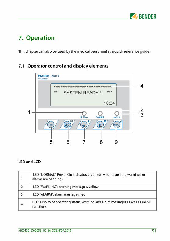
7.1 Operator control and display elements
LED and LCD
1 LED "NORMAL": Power On indicator, green (only lights up if no warnings or alarms are pending)
2 LED "WARNING": warning messages, yellow
3 LED "ALARM": alarm messages, red
4LCD: Display of operating status, warning and alarm messages as well as menu functions
************************************ SYSTEM READY ! ***
COMTRAXX©
1
765
23
4
8 9
51MK2430_D00053_00_M_XXEN/07.2015

Operation
Functions of the buttons:
In operating mode In menu mode
5
"TEST" buttonPress and release: LED testPress and hold down: Trigger the test of assigned devices (insulation moni-toring devices, LIM, GFCI).
No function
6 button (mute button)
Mute the buzzer after an alarm mes-sage/acknowledge the alarm
"ESC" button Exit function (without saving) or go up one menu level.When the buzzer is activated, the ESC button will mute the buzzer.
7
button (scroll)Scroll through the warnings and alarms if there is more than one mes-sage pending
Arrow button "▲"to move up in the menu
8 button (additional text)
Toggle between display text and addi-tional alarm text (if available)
Arrow button "▼"to move down in the menu
9
"MENU" buttonStarts menu mode for setting the MK800;for display and control functions
"↵" button (ENTER button)To confirm the selected menu item
52 MK2430_D00053_00_M_XXEN/07.2015

Operation
7.2 Quick reference guideThe illustrations below serve as examples.
7.2.1 Display under normal operating conditionsThere are no warnings or alarms pending. The green "Normal" LED is lit. The LC display shows the programmed standard display. A maximum of 3 measuring values can be displayed in lines 1…3. Example:
– Line 1…3: User-definable standard display text– Line 4: Status bar, indicates the time of day (can be switched off).
7.2.2 Display during fault conditionA warning or an alarm message exists. Depending on the type of fault, either the yellow LED "Warning" or the red LED
"Alarm" will light up. The green LED "Normal" no longer lights up. The buzzer sounds simultaneously. If the cause of fault cannot be remedied
immediately, the buzzer can be muted by pressing the " " (6) button. The LC display shows details about the message.
– Line 1: Standard display: "System:" Enter user-defined text here: "Inten-sive care unit 03"
– Line 2…3: Message text, measured value (if available)
Power supply: OKMed. gases: OK
09:50
Intensive care unit 03Insulation faultMeasured value 43 kΩxx/yy zzz 09:50
53MK2430_D00053_00_M_XXEN/07.2015

Operation
– Line 4: Status linexx = Consecutive number of message displayed yy = Number of pending messages
= Message text page, in this case page 1zzz = Insulation fault location or test in progress
(refer to table)09:50 = Time (example)
Possible displays during insulation fault location or testing:
Only when the external bus is in "Off" position:
Press the button" " (7) to receive further information.
– Line 1: Date and time the message occurred– Line 2: Device triggering the message– Line 3: Address and channel of the device triggering the message
zzz Meaning
EDSa EDS insulation fault location in progress (automatic)
EDSp Continuous EDS insulation fault location in progress
EDSs Single-pass EDS fault location in progress
EDSEDS insulation fault location process has been completed, the current measuring sequence is still running
TESTTest is running. The message "TEST" flashes if the message cur-rently displayed has caused the test.
noMA No master on the internal bus
MAST Device is "substitute master" on the internal bus.
since: 25:01:12 16:52Device: IsometerAddr/Ch: 003/01xx/yy 17:30
54 MK2430_D00053_00_M_XXEN/07.2015
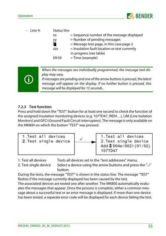
Operation
– Line 4: Status linexx = Sequence number of the message displayed yy = Number of pending messages
= Message text page, in this case page 2zzz = Insulation fault location or test currently in progress (see table) 09:50 = Time (example)
7.2.3 Test functionPress and hold down the "TEST" button for at least one second to check the function of the assigned insulation monitoring devices (e.g. 107TD47, IRDH…), LIM (Line Isolation Monitors) and GFCI (Ground Fault Circuit interrupters). The message is only available on the MK800 on which the button "TEST" was pressed.
1. Test all devices Tests all devices set in the "test addresses" menu.2. Test single device Select a device using the arrow buttons and press the "↵"
button.During the tests, the message "TEST" is shown in the status line. The message "TEST" flashes if the message currently displayed has been caused by the test.The associated devices are tested one after another. The MK800 automatically evalu-ates the messages that appear. Once the process is complete, either a common mes-sage about a successful test or an error message is displayed. If more than one device has been tested, a separate error code will be displayed for each device failing the test.
When the messages are individually programmed, the message text dis-play may vary.If messages are pending and one of the arrow buttons is pressed, the latestmessage will appear on the display. If no further button is pressed, thismessage will be displayed for 15 seconds.
1.Test all devices2.Test single device
1.Test all devices2.Test single deviceAdd 004e/002i(01/02)107TD47
55MK2430_D00053_00_M_XXEN/07.2015

Operation
The following error codes are displayed in the event of an Isometer® failing the test:
Notes regarding error codes For MK800 devices operating as slaves on the BMS bus a timeout of 50 seconds
applies to error code 0 and 14. Error code 14 occurs when the slave is requested to carry out a test; the test com-
mand, however, cannot be sent because MK800 was not queried. This can be the case if the address gap upstream of the MK800 is so large that the master does not query the MK800 (refer to "BMS bus" operating manual). This error code is not so much an indication of a faulty ISOMETER® but that the BMS bus system is faulty.
Error code
Error code description for the 107TD47 ISOMETER® (hospital)
Error code description for the IRDH… ISOMETER® (industry)
Note
0
No messages received from the ISOMETER® although the test command was confirmed by the ISOMETER®.
No messages received from the ISOMETER® although the test command was confirmed by the ISOMETER®.
1 Only insulation fault message received
Only insulation fault message from channel 1 received
Channel 1
2 Only overload message receivedOnly insulation fault message from channel 2 received
Channel 2
3 Only insulation fault message and overload message received
Channel 1 and 2
4 Only overtemperature message received
Channel 3
5 Only insulation fault message and overtemperature message received
Channel 1 and 3
6 Only overload message and over-temperature message received
Channel 2 and 3
14 Test command could not be sent because no query was made (slave).
Test command could not be sent because no query was made (slave).
Slave only
15 ISOMETER® did not confirm the test command (no answer).
ISOMETER® did not confirm the test command (no answer).
56 MK2430_D00053_00_M_XXEN/07.2015

8. Menu mode: Operation and setting
8.1 Switching on and calling the main menuIf the MK800 is connected to the power supply, the following information appears on the display for approx. 3 seconds. Details about the address and the firmware version of the device are displayed. This information is also available in the "Info" menu.
If there are no messages pending, the standard display will be shown when the starting procedure is completed.
The TMK-SET software allows you to change the standard display and the message texts.
If the MK800 has not been turned on for several days, a longer time may berequired for start-up (approx. 30 seconds). In this case, enter time and date again.
MK800-11 Addr.:01/001Software 4.02 D279Date: 02/05/12www.bender.de
*********************** SYSTEM READY! **Bender GmbH Grünberg 09:50
57MK2430_D00053_00_M_XXEN/07.2015

Menu mode: Operation and setting
Press the button "Menu" to open the main menu.
5.Control6.External devices7.Info
The following buttons can be used in the main menu: ESC Exit function or go up one menu level▲, ▼ Select menu items
↵ Confirm the selected menu item (Enter)
The menu mode is exited automatically if no buttons are pressed in one ofthe menus for more than five minutes (exception: "test communication" inthe "Control" menu and "position mode" in the "External devices" menu).
Some menus are password-protected. Password protection is only effec-tive if the password has been enabled (switched on).When an attempt is made to open one of these menus, the password entryscreen appears automatically:
Once a valid password has been entered, full access will be given to allmenus (except to the service menu) until menu mode is exited.
1.Exit2.Values3.History4.Settings
Please enter Password0 0 0
58 MK2430_D00053_00_M_XXEN/07.2015

Menu mode: Operation and setting
8.2 Menu overview diagramThe following diagram will help you to navigate through the menus:
1":'��
-"�8�����
."!�������
="6 ��� �
/"3��� ��
@":'��������������
A"���
-"���������������
1":'��
/"+�������������
."8��������������
="��������������
@" �<<��
A"6 �� �������
"6� �$
B"C�������
1�"���������
11";����
1-"#���� ��
1/"!����������
1":'��
-";�����%�����6����(
/":�!������&�� �
."+����6 ��������� �
="!�����;������ ��
59MK2430_D00053_00_M_XXEN/07.2015
Menu mode: Operation and setting
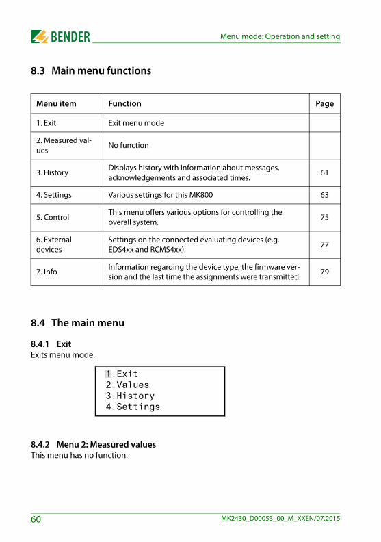
8.3 Main menu functions
8.4 The main menu
8.4.1 ExitExits menu mode.
8.4.2 Menu 2: Measured valuesThis menu has no function.
Menu item Function Page
1. Exit Exit menu mode
2. Measured val-ues
No function
3. History Displays history with information about messages, acknowledgements and associated times.
61
4. Settings Various settings for this MK800 63
5. ControlThis menu offers various options for controlling the overall system.
75
6. External devices
Settings on the connected evaluating devices (e.g. EDS4xx and RCMS4xx).
77
7. InfoInformation regarding the device type, the firmware ver-sion and the last time the assignments were transmitted.
79
1.Exit2.Values3.History4.Settings
60 MK2430_D00053_00_M_XXEN/07.2015

Menu mode: Operation and setting
8.4.3 Menu 3: HistoryThe MK800 can store up to 1000 messages in the history memory (ring buffer). If more than 1000 messages are recorded by the MK800, message 1001 will overwrite the entry 1.The "History" menu provides information about messages, acknowledgements and their time stamps. It also indicates whether an alarm is still pending or when it was ac-knowledged or muted with the " " button. The complete content of the history mem-ory with additional texts and address of the device sending the message can be displayed on a PC and printed out using the TMK-History software version V3 or higher. All interfaces of MK800 can be used for connection.
1. Use the arrow buttons to select the entry you require. The latest entry appears first on the display. Older messages can be selected using the arrow buttons.
2. Press the "↵" button to call up the message text of the selected entry. The path the message took to reach MK800 appears in the last line. In this case an insulation fault was received via the internal BMS bus from address 003, chan-nel 01. The table on the following page contains information about other possible displays.
3. If analogue values are displayed, as shown in the example above, the maxi-mum and minimum values can be displayed by pressing the "" button.
4. Press the "↵" to return to entry selection.Repeat these operating steps for all messages you need. Then press "ESC" button to exit the menu.
Entry: 0003/0003From: 04.12.11 16:00Ack.: 04.12.11 16:00To: 04.12.11 16:03
System: 01Insulation faultMeas. value: Addr/Ch: 01/003/01
61MK2430_D00053_00_M_XXEN/07.2015
Menu mode: Operation and setting
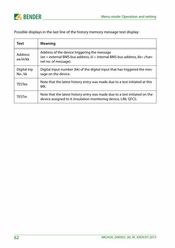
Possible displays in the last line of the history memory message text display:
Text Meaning
Address: ee/iii/kk
Address of the device triggering the message (ee = external BMS bus address, iii = internal BMS bus address, kk= chan-nel no. of message).
Digital Inp No.: kk
Digital input number (kk) of the digital input that has triggered the mes-sage on the device.
TESTexNote that the latest history entry was made due to a test initiated at this MK.
TESTinNote that the latest history entry was made due to a test initiated on the device assigned to it (insulation monitoring device, LIM, GFCI).
62 MK2430_D00053_00_M_XXEN/07.2015

Menu mode: Operation and setting
8.4.4 Menu 4: SettingsThe following menu items are available for configuring the MK800:
Menu item Function Page
1. Exit Exit "Settings" menu; go up one menu level
2. Alarm addresses
Setting bus addresses for devices so that the alarm mes-sages of these devices can be displayed on this MK800.
64
3. Test addressesSetting bus addresses for devices which are required to carry out a test when the "TEST" button is pressed.
65
4. Measured value addresses
No function 66
5. Digital inputs
MK800-11only: Setting of the operating behaviour for digital inputs.
67
6. Buzzer (and LED)
Setting of the frequency and repetition rate of buzzer sig-nal.
69
7. Common reset
Determine if the MK800 should respond to a common acknowledgement initiated by the reset button of another device.
69
8. Clock
Setting of the date and time of the real-time clock on this MK800. At the same time this setting is sent via BMS bus and all other devices are synchronised. The device with address 1 (MK800 or alarm indicator and operator panel) synchronises all other devices every hour.
70
9. LanguageSelection of operating language for the MK800 (German or English).
71
10. InterfaceSetting of the device address and baud rate for this MK800.
72
11. RelayMode of operation and function of the common alarm relay (alarm relay) on the MK800-11
73
12. Password Change password, activate/deactivate password. 74
13. Service menu
These settings can only be made by authorised Bender Service personnel. Retrieve information about the device status, enter settings for special operating conditions and execute a firmware update.
74
63MK2430_D00053_00_M_XXEN/07.2015
Menu mode: Operation and setting
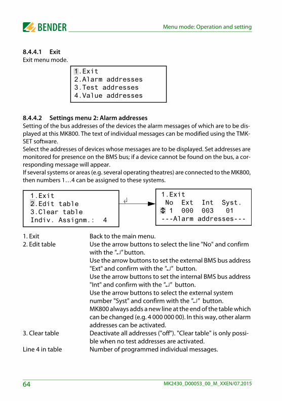
8.4.4.1 ExitExit menu mode.
8.4.4.2 Settings menu 2: Alarm addressesSetting of the bus addresses of the devices the alarm messages of which are to be dis-played at this MK800. The text of individual messages can be modified using the TMK-SET software. Select the addresses of devices whose messages are to be displayed. Set addresses are monitored for presence on the BMS bus; if a device cannot be found on the bus, a cor-responding message will appear. If several systems or areas (e.g. several operating theatres) are connected to the MK800, then numbers 1…4 can be assigned to these systems.
1. Exit Back to the main menu.2. Edit table Use the arrow buttons to select the line "No" and confirm
with the "↵" button. Use the arrow buttons to set the external BMS bus address "Ext" and confirm with the "↵" button.Use the arrow buttons to set the internal BMS bus address "Int" and confirm with the "↵" button.Use the arrow buttons to select the external system number "Syst" and confirm with the "↵" button.MK800 always adds a new line at the end of the table which can be changed (e.g. 4 000 000 00). In this way, other alarm addresses can be activated.
3. Clear table Deactivate all addresses ("off"). "Clear table" is only possi-ble when no test addresses are activated.
Line 4 in table Number of programmed individual messages.
1.Exit2.Alarm addresses3.Test addresses4.Value addresses
1.Exit No Ext Int Syst. 1 000 003 01---Alarm addresses---
1.Exit2.Edit table3.Clear tableIndiv. Assignm.: 4
64 MK2430_D00053_00_M_XXEN/07.2015

Menu mode: Operation and setting
Possible settings for the system number "Syst":
8.4.4.3 Settings menu 3: Test addressesSet the bus addresses for insulation monitoring devices (z. B. 107TD47, IRDH…), transfer switching devices with monitoring functions (ATICS®), LIM (Line Isolation Monitors) and GFCI (Ground Fault Circuit interrupters), which are required to carry out a test when the "TEST" button is pressed. The setting can only be made for devices which have also been activated in the "Alarm addresses" menu and/or programmed for individual alarm texts. Individual alarm texts are a minimum requirement for Channel 1…3 (setting "107TD47") Channel 1, 2 (setting "IRDHxxx") Channel 1 (setting "GFCI") Channel 1, 2, 3, 6, 7, 9 (setting "LIM")
1. Exit Back to the main menu.2. Edit table Use the arrow buttons to select the line "No" and confirm
with the "↵" button. Use the arrow buttons to set the external BMS bus address "Ext" and confirm with the "↵" button.Use the arrow buttons to set the internal BMS bus address "Int" and confirm with the "↵" button.
Syst Meaning
00 No text appears in line 1 of the alarm message.
01…04 Texts of "System 01" to "System 04" are displayed.
T Programmed text is displayed.
Off Deletes the current line of the table
1.Exit2.Edit table 3.Clear table
1.Exit Nr Ext Int Type 1 000 003 107TD---Test addresses---
65MK2430_D00053_00_M_XXEN/07.2015

Menu mode: Operation and setting
Use the arrow buttons to select insulation monitoring de-vice "Type" and confirm with the "↵" button.MK800 always adds a new line at the end of the table which can be changed (e.g. 4 000 000 off). This way, other test ad-dresses can be activated.
3. Clear table Deactivate all addresses ("off").
Possible settings for "Type":
8.4.4.4 Settings menu 4: Value addressesCurrently has no function.
Syst Meaning
107TD Insulation monitoring device, e. g. 107TD47
IRDHx Industrial insulation monitoring device, e. g. IRDH…
GFCI Ground Fault Circuit Interrupter
LIM Line Isolation Monitor
Off Deletes the current line of the table
66 MK2430_D00053_00_M_XXEN/07.2015

Menu mode: Operation and setting
8.4.4.5 Settings menu 5: Digital inputsSetting the operating behaviour for the digital inputs IN1…IN16 (for MK800-11 only). The following setting can be made individually for each input: "24V" (high) or "0V" (low). When the input is set to "24V" an alarm message will be sent when the voltage at the input is 10…30 V. When the input is set to "0V" an alarm message will be sent when the voltage is 0…2 V. It is for this reason that you should always set unused digital inputs to "off".
1. Exit Back to the main menu.2. Operation mode Select the digital input using the arrow buttons and con-
firm with the"↵" button.Use the arrow buttons to select "0 V", "24 V" or "Off". Press the "↵" button to accept the entry. Repeat the procedure to set more digital inputs.
3. Function Set the message text category to "neutral" or "medical", see chapter "Alarm texts for digital inputs" on page 67.
Alarm texts for digital inputsA neutral or specific alarm message can be assigned to all digital inputs. A neutral alarm message indicates the alarm, the channel and the address of the device triggering the alarm. In comparison, the specific alarm message (medical) signals a non-modifiable pre-programmed alarm e. g. "Alarm: oxygen". Assign the inputs according to the table "Neutral and specific alarm messages" on page 68.The TMK-SET PC software can be used to assign other messages to individual or all dig-ital inputs.The alarm messages in the following table are sent to other MK… or alarm indicator and operator panels via BMS bus and displayed there in plain text format.
If freely programmable alarm messages need to be displayed on a different MK800 or on an alarm indicator and operator panel, the alarm messages programmed for the dis-play device must be identical.
1.Exit2.Input: 01: 24V Alarm at 24V---Digital inputs---
1.Exit2.Operat. principle3.Function: neutral
67MK2430_D00053_00_M_XXEN/07.2015
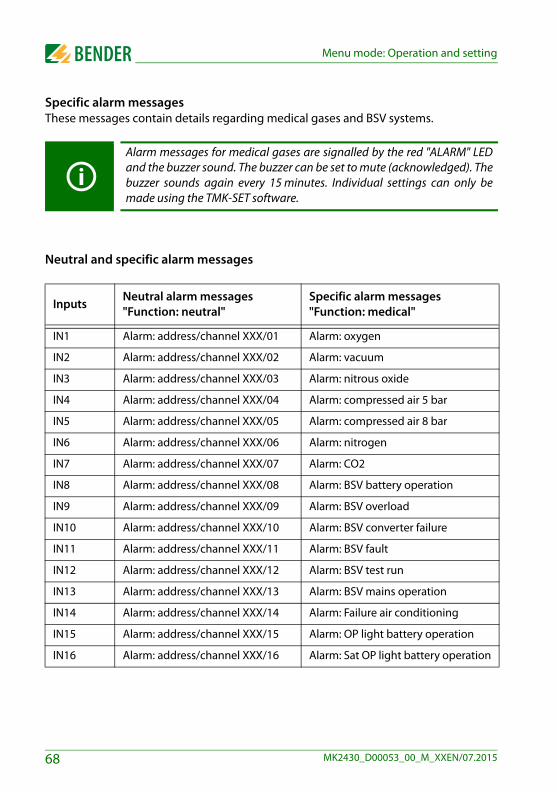
Menu mode: Operation and setting
Specific alarm messagesThese messages contain details regarding medical gases and BSV systems.
Neutral and specific alarm messages
Alarm messages for medical gases are signalled by the red "ALARM" LEDand the buzzer sound. The buzzer can be set to mute (acknowledged). Thebuzzer sounds again every 15 minutes. Individual settings can only bemade using the TMK-SET software.
Inputs Neutral alarm messages"Function: neutral"
Specific alarm messages"Function: medical"
IN1 Alarm: address/channel XXX/01 Alarm: oxygen
IN2 Alarm: address/channel XXX/02 Alarm: vacuum
IN3 Alarm: address/channel XXX/03 Alarm: nitrous oxide
IN4 Alarm: address/channel XXX/04 Alarm: compressed air 5 bar
IN5 Alarm: address/channel XXX/05 Alarm: compressed air 8 bar
IN6 Alarm: address/channel XXX/06 Alarm: nitrogen
IN7 Alarm: address/channel XXX/07 Alarm: CO2
IN8 Alarm: address/channel XXX/08 Alarm: BSV battery operation
IN9 Alarm: address/channel XXX/09 Alarm: BSV overload
IN10 Alarm: address/channel XXX/10 Alarm: BSV converter failure
IN11 Alarm: address/channel XXX/11 Alarm: BSV fault
IN12 Alarm: address/channel XXX/12 Alarm: BSV test run
IN13 Alarm: address/channel XXX/13 Alarm: BSV mains operation
IN14 Alarm: address/channel XXX/14 Alarm: Failure air conditioning
IN15 Alarm: address/channel XXX/15 Alarm: OP light battery operation
IN16 Alarm: address/channel XXX/16 Alarm: Sat OP light battery operation
68 MK2430_D00053_00_M_XXEN/07.2015

Menu mode: Operation and setting
8.4.4.6 Settings menu 6: Buzzer (and LED)The buzzer will sound in the event of an alarm. Setting of the audio frequency and rep-etition rate of the two consecutive buzzer sounds.
1. Exit Back to the main menu.2. Warning3. Alarm A variety of signals can be preset for "Warning" and
"Alarm". An individual buzzer sound can be selected via TMK-SET.
During the setting procedure the selected buzzer signal sounds and the LED lights up or flashes.
8.4.4.7 Settings menu 7: Common resetSetting indicating whether this MK800 should respond (On) or not (Off) to the acknowl-edgement of the buzzer (buzzer mute) initiated by pressing buzzer mute button " " on another MK… or TM… operator panel. When common acknowledgement is activated, a buzzer of an MK800 can also be acknowledged (muted) by an MK… or a TM… in another room. The alarm message itself will remain visible on the display until its cause has been rec-tified.
1. Exit Back to the main menu.2. C.Reset Int: Setting for the internal BMS bus:
"On" buzzer can be acknowledged externally"Off" buzzer cannot be acknowledged externally
2. C.Reset Ext.: Setting for the external BMS bus: "On" buzzer can be acknowledged externally"Off" buzzer cannot be acknowledged externally
1.Exit2.Warning: 63.Alarm: 8
1.Exit2.C.Reset Int.: On3.C.Reset Ext.: On
69MK2430_D00053_00_M_XXEN/07.2015

Menu mode: Operation and setting
8.4.4.8 Settings menu 8: ClockThis menu is used to set the time, date and date format display. These settings remain stored after a supply failure for approx. 5 days. The clock adjusts itself automatically to the Central European Summertime (CEST) and Wintertime (CET). Adjust the time again if the time no longer corresponds to the local time after automatic switchover. The automatic switchover can be deactivated (menu item "5. Summertime").
1. Exit Back to the main menu2. Time Set the time (hours and minutes)3. Date Set date (according to the format indicated in line 4)4. Format Select German (tt. mm. jj) or
American (mm/ tt/jj)5. Daylight sav. Setting for automatic switchover to
Central European Summertime:auto automatic switchover off no switchover
Time and date of the system can be set on any MK… or TM… panel. Thesettings are transferred via the BMS bus to the master device (address 1),which transfers the settings to all other MK… or TM… panels.
1.Exit (CEST)2.Time: 11:453.Date: 27.07.114.Format: dd.mm.yy
70 MK2430_D00053_00_M_XXEN/07.2015

Menu mode: Operation and setting
8.4.4.9 Settings menu 9: LanguageSelection of the language for menu operation and message display (alarm and operat-ing messages) at the MK800. Changes will be effective immediately.
1. Exit Back to the main menu.2. Menu Set the operating language for the menu: German or
English3. Mess. Select the language for the message display. You may se-
lect:
German English French
Italian Spanish Portuguese
Portuguese (Brazil) Dutch Norwegian
Swedish Finnish Danish
Polish Hungarian Czech
Slovenian Croatian Serbian
Turkish Indonesian Russian
The language setting activates the language-specific characters. Howev-er, user-defined alarm texts remain unchanged. For this reason, youshould only program and transfer individual alarm texts after languageselection.
1.Exit2.Menu: English3.Messg.: English
71MK2430_D00053_00_M_XXEN/07.2015

Menu mode: Operation and setting
8.4.4.10 Settings menu 10: InterfaceSetting of the own device address and the transfer rate (baud rate) for the connection to the BMS bus.
1.Exit Back to the main menu.2. Addr. external Setting of the external BMS bus address.
Addresses between 1 and 99 may be selected (factory setting: 1)."Off" = external Bus is switched off.
3. Baud external The baud rate of the external BMS bus is selectable: 19200, 38400 or 57600 bit/s, (factory setting: 57600 bit/s). This set-ting can also be carried out when the external bus is switched off.
4. Addr. internal Setting of the internal BMS bus address. Addresses between 1 and 150* may be selected, (factory setting: 1).This setting can only be changed when the external bus has been switched off before.On the internal BMS bus the baud rate is set to a fixed value of 9600 bits/s.
Change the corresponding device address if several MK800 are connected to one BMS bus. One MK800 must have the address 1 (master). All other MK800 are addressed in consecutive order: 2,3,4…. Gaps between addresses should be avoided. Only in this way the functionality of the system can be ensured (also refer to the "BMS bus" manual).
Data exchange will only work between devices with the same baud rate.
* The addresses 100…103 are intended for special tasks (e.g. programming) and thereforecannot be assigned.
1.Exit2.Addr. ext.: 13.Baud ext.: 576004.Addr. int.: 1
72 MK2430_D00053_00_M_XXEN/07.2015

Menu mode: Operation and setting
8.4.4.11 Settings menu 11: RelaysSet the operation mode and function for the optional alarm relay of the alarm indicator and test combination. This menu only exists on the MK800..-11.
1. Exit Back to the main menu.2. Operation princ. Set the operation mode:
N/O operationN/C operation
3. Mode Optional alarm relay switches in the event of:
Setting Description
Programma-ble
Programming via TMK-SET -> individual alarms or operating messages
Device errorRelay switches in case of an internal fault on the MK800-11.
Common fault alarm
Relay switches in case of any warning or alarm message.
Device failure
Relay switches as soon as the MK800 recognises a device failure.
TestRelay switches for approx. 1 second once a test has been started via the "TEST“ button on the assigned devices (insulation monitoring devices, LIM, GFCI).
Buzzer
The relay switches as soon as the buzzer sounds. Also other signalling devices can be installed to indicate pend-ing messages on the TM800.
1.Exit2.Operat.princ.: N/O3.Mode: Device error
73MK2430_D00053_00_M_XXEN/07.2015
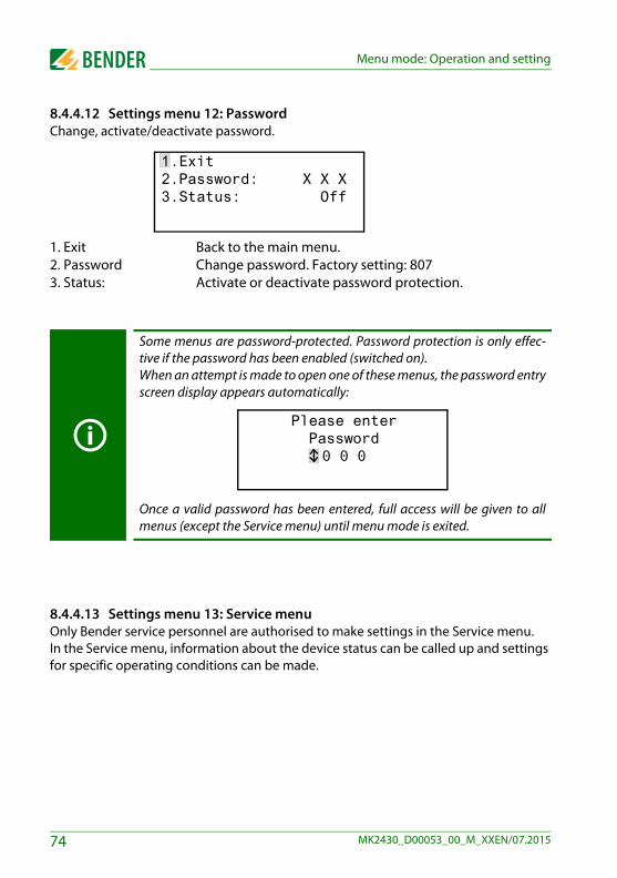
Menu mode: Operation and setting
8.4.4.12 Settings menu 12: PasswordChange, activate/deactivate password.
1. Exit Back to the main menu.2. Password Change password. Factory setting: 8073. Status: Activate or deactivate password protection.
8.4.4.13 Settings menu 13: Service menuOnly Bender service personnel are authorised to make settings in the Service menu. In the Service menu, information about the device status can be called up and settings for specific operating conditions can be made.
Some menus are password-protected. Password protection is only effec-tive if the password has been enabled (switched on).When an attempt is made to open one of these menus, the password entryscreen display appears automatically:
Once a valid password has been entered, full access will be given to allmenus (except the Service menu) until menu mode is exited.
1.Exit2.Password: X X X3.Status: Off
Please enter Password0 0 0
74 MK2430_D00053_00_M_XXEN/07.2015

Menu mode: Operation and setting
8.4.5 Menu 5: ControlThis menu offers various options for controlling individual devices or the overall system:
8.4.5.1 ExitExit menu mode.
8.4.5.2 Control menu 2: Reset (AlarmClear)Press the "↵" button to reset all fault messages pending on the BMS bus. "Reset done!" will then appear in the last line.
This reset command is sent via the BMS bus. Note that some devices (e.g. PRC487) do not respond to this reset.
Menu item Function Page
1. Exit Exit "Control" menu; go up one menu level
2. Reset (AlarmClear)
Resetting all fault messages pending on the BMS bus 75
3. EDS Start/StopManual starting/stopping of test procedure on the EDS system
76
4. Test Communication
Testing of communication via the BMS bus (MK800-11 only).
76
5. Reset modeDetermine whether a reset is to be carried out via the internal BMS bus only or also via the external BMS bus.
77
1.Exit2.Reset (AlarmClear) 3.EDS start/stop4.Test Communication
1.Exit2.Reset (AlarmClear) 3.EDS start/stop Reset done!
75MK2430_D00053_00_M_XXEN/07.2015

Menu mode: Operation and setting
8.4.5.3 Control menu 3: EDS Start/StopPress the "↵" button to manually start and stop the measuring procedure of the EDS sys-tem. This function can only be activated by the master. The current status appears in the last line.
Insulation fault location running Once started, the EDS4xx-12 and PGH47x run continuously. If the menu is exited, the stand-ard display "EDSp" will appear in the last line in order to indicate continuous running*.
Insulation fault location stop Stops the EDS4xx-12 and PGH47x from contin-uous operation. If you exit the menu, the standard display "EDS" will appear in the last line until the current test pass finishes.
* Other abbreviations that might appear in the last line of the display:EDSa Automatic mode: Insulation fault location has been started
by e.g. ISOMETER®, ATICS® or isoMED427P on PGH47x.EDSs Single mode: A single run has been started by IN2 on
PGH47x.
8.4.5.4 Control menu 4: Test communicationTesting the communication via the BMS bus. For this purpose, a fault message is simu-lated on a digital input. This fault message is sent to evaluating devices (such as MK…, TM…, SMO…) via the BMS bus. Check that these devices are responding to the fault message as requested.
Channel 003 Setting the channel whose message is to be activated.
1.Exit2.Reset (AlarmClear) 3.EDS start/stopEDS system running
1.Exit2.Reset (AlarmClear) 3.EDS start/stopEDS system stop
1.Exit2.Channel: 3
-Test communication-
76 MK2430_D00053_00_M_XXEN/07.2015

Menu mode: Operation and setting
8.4.5.5 Control menu 5: Reset modeSet whether the reset command should have an effect on the internal BMS bus only or also on the external bus: Setting possibilities
– internal only– internal and external
8.4.6 Menu 6: External devicesThis menu is used to set and control external devices. Functions include for example displaying information about connected devices (address, software version, device type) or continuous displaying a channel on a connected evaluating device.
Select the BMS bus to which the external device is connected.
Internal bus Devices connected to the internal bus of this MK800 can be displayed and adjusted.
External bus Devices connected to the external bus of this MK800 can be displayed and adjusted. If other Bender devices utilising an internal bus (TM…, MK…) are addressed via the exter-nal bus, also the devices connected to this internal bus can be displayed and adjusted. Devices which can be parameterised:EDS46x, EDS47x, EDS49x, RCMS460, RCMS470, RCMS490
1. Exit 2. Internal interface3. External interface
77MK2430_D00053_00_M_XXEN/07.2015

Menu mode: Operation and setting
All devices connected to the BMS bus are indicated. Select the address of the external device to be displayed (e.g. EDS4xx-12 or RCMS4xx-12).
Address, type and version of the connected device are displayed. If no device is detect-ed under the address, the character "?" appears. Use the arrow buttons to select the ad-dress of the external device and confirm your selection with the "↵" button.
If the device has been recognised, the MK800 will read the current settings of the con-nected device. The first line of the display shows the device type.Use the Up/Down buttons to select the appropriate function or device setting and con-firm with the "↵" button. Example:
in the EDS or RCMS menu there are various setting possibilities available. These are de-scribed in more detail in the operating manuals for the corresponding systems.
1. Exit (internal!)001: MK800-11 V4.04002: EDS470 V3.20003: 107TD47 V2.52
1. Exit (107TD47)2. Position mode
1. Exit (107TD47) 2. Channel: 1 Re= 20 KΩ
1. Exit (EDS470)2. General3. Channel4. Relay
78 MK2430_D00053_00_M_XXEN/07.2015

Menu mode: Operation and setting
8.4.7 Menu 7: Info
Information regarding device type, firmware version and last time assignments were transmitted. Assignments are settings carried out via PC software (e.g. TMK-SET):
Enter standard text Assign texts and functions to the alarm messages and digital inputs of the MK800 Set parameters
Select:
ESC Exit menu mode
▲ Show date of last assignment transmission:
▼(press once) Show version of standard texts and version of the boot loader (in-ternal software for updates).
MK800-11 Addr.:01/001Software 4.02 D279Date: 02/09/12www.bender.de
Assignmentsprogrammedon: 12.07.09 07:07
Text version: 2.00Bootloader 2.20
79MK2430_D00053_00_M_XXEN/07.2015

Menu mode: Operation and setting
▼(press twice) The alarm addresses, test addresses and individual mes-sages and the number of the devices will be displayed. Switching commands: On MK800 without function.
↵ Go back to the main menu
8.5 Overview of setting optionsThe MK800 supports various settings. The table below shows where the individual pa-rameters can be set.
Alarm addresses: 0Test addresses: 0Indiv. Assignm.: 0Switch.cmd.: 00/00
80 MK2430_D00053_00_M_XXEN/07.2015

Menu mode: Operation and setting
Para
met
er
Adj
usta
ble
via
N
ame
Ran
ge
Fact
ory
setti
ng
Use
rse
tting
TM
800/
MK
800
Men
u no
. TM
800/
MK
800
Serv
ice
men
u ite
m
TMK
set
Para
met
er m
enu
Not
e
Buzz
er s
ettin
gs
War
ning
A
larm
(0
),1..9
(0
),1..9
6 8
4.6.
2 4.
6.3
--Bu
zzer
set
tings
Fr
eque
ncy
setti
ng 1
, 2, b
uzze
r int
erva
l for
ALA
RM
and
W
ARN
ING
, sel
ectio
n of
pre
defin
ed m
essa
ges
(pre
set)
Com
mon
rese
t I
nt.
Ext
. y/
n y/
n y y
4.7.
2 4.
7.3
--Bu
zzer
mut
e vi
a bu
s R
S-4
85 in
t.
RS
-485
ext
.
Set
ting
whe
ther
an
exte
rnal
dev
ice
shou
ld re
spon
d to
an
alar
m a
ckno
wle
dgem
ent t
o m
ute
the
buzz
er o
n th
e in
t. (e
xt.)
BM
S
Clo
ck/d
ate
For
mat
S
umm
ertim
e dd
.mm
.yy
/ m
m/d
d/yy
au
to/o
ff
dd.m
m.y
y au
to4.
8.4
4.8.
5 --
Clo
ck /D
ate/
CE
ST
auto
mat
ic
Set
the
time
and
date
/ au
tom
at. s
umm
ertim
e/w
inte
rtim
e on
/off
Lang
uage
Men
u M
essa
ge
Deu
tsch
/Eng
lish
20 la
ngua
ges
Deu
tsch
Deu
tsch
4.9.
2 4.
9.3
--La
ngua
ge
Men
u la
ngua
ge s
ettin
g
Inte
rface
A
ddr.
exte
rnal
Bau
d ex
tern
al
Add
r. in
tern
al
1..9
9/of
f
1980
0.. 5
7600
1.
.150
/off
1
5760
0 1
4.10
.2
4.10
.3
4.10
.4
--
RS
-485
set
tings
ex
tern
al a
ddre
ss
exte
rnal
bau
d ra
te
inte
rnal
add
ress
Sw
itch
off u
nuse
d ex
tern
al in
terfa
ce
Ext
. BM
S o
ff fo
r sin
gle
pane
ls: f
aste
r int
erna
l co
mm
unic
atio
n.
In c
ase
of c
omm
unic
atio
n pr
oble
ms,
redu
ce th
e ba
ud
rate
. In
t. B
MS
off
for p
aral
lel p
anel
: fas
ter e
xter
nal
com
mun
icat
ion.
In
tern
al a
ddre
ss c
an o
nly
be s
et w
hen
the
ext.
BM
S is
sw
itche
d of
f. D
igita
l out
put 1
Fu
nctio
n O
pera
ting
mod
e
4.
11
--
Dig
ital
outp
ut 1
S
ettin
g of
the
func
tion
for t
he fi
rst d
igita
l out
put o
r rel
ay:
Test
/dev
ice
erro
r/com
mon
ala
rm/d
evic
e fa
ilure
/ pr
ogra
mm
able
Pa
ssw
ord
prom
pt
Pas
swor
d S
tatu
s X
X X
on
/off
807
on4.
12.2
4.
12.3
--
Pass
wor
d re
quire
d C
hang
ing
the
pass
wor
d A
ctiv
atin
g/de
activ
atin
g th
e pa
ssw
ord
prom
pt
Res
et m
ode
in
t./in
t.+ex
t. in
t.
5.5
--
Res
et m
ode
*)
Det
erm
ine
the
effe
ct o
f the
RE
SE
T co
mm
and
(for d
evic
es
with
faul
t mem
ory:
ED
S, R
CM
S, I
SOM
ETE
R) v
ia B
MS
H
isto
ry b
uffe
r --
--
--
--
2. H
isto
ry
2.2
Cle
ar H
isto
ry
Dia
gnos
tic in
form
atio
n H
isto
ry m
emor
y re
set
Dis
play
the
num
ber o
f ava
ilabl
e da
ta re
cord
s.
Cle
ar a
ll da
ta re
cord
s in
the
hist
ory
mem
ory.
R
eset
cou
nter
--
--
--
--
3 R
eset
cou
nter
3.2.
Cle
ar R
eset
Cou
nt.
Res
et c
ount
er
rese
t
Dis
play
the
Pow
er-D
own,
Wat
chdo
g an
d ex
tern
al re
set
coun
ters
Res
et a
ll re
set c
ount
ers
--
--
--
--
-- 4.
Dig
italIN
/Tas
kbits
--
Indi
catio
n of
the
digi
tal i
nput
sta
tes
and
task
s --
--
--
--
--
5. B
I800
-In/B
MIx
x-O
ut
-- a)
Tes
t of i
ndiv
idua
l out
puts
: set
the
outp
ut n
umbe
r b)
Dis
play
the
butto
ns th
at a
re p
ress
ed
Tim
e-O
ut in
t. Ti
me-
Out
ext
. 42
ms…
200
ms
10 m
s…10
0 m
s 60
ms
10 m
s
--
6. S
ettin
g Ti
meo
ut/S
P
6.2.
Tim
e-O
ut in
t. 6.
3. T
ime-
Out
ext
.
Tim
eout
R
S485
int.*
) /
RS4
85 e
xt.*
)
Tim
eout
on
int.
BM
S: 0
60 m
s Ti
meo
ut o
n ex
t. B
MS
: 010
ms
at 5
6 kB
d M
ay o
nly
be c
hang
ed fo
r tes
t pur
pose
s!
Dis
play
the
stac
k lo
ad i
n %
(R
: Pro
gram
sta
ck; C
: Dat
a st
ack)
--
--
--
--
--
7. T
imin
g An
alys
is 1
7.
2 R
eset
val
ues
-- In
dica
tion
(and
rese
t) of
the
max
. res
pons
e tim
es w
ith th
e as
soci
ated
add
ress
on
the
int.
and
ext.
bus
81MK2430_D00053_00_M_XXEN/07.2015

Menu mode: Operation and setting
Param
eter
A
djus
tabl
e vi
a
Nam
e R
ange
Fa
ctor
y se
tting
U
ser
setti
ng
TM80
0/M
K80
0M
enu
no.
TM80
0/M
K80
0Se
rvic
e m
enu
item
TM
Kse
t Pa
ram
eter
men
u N
ote
Max
Slav
eTim
e 50
0..3
000
ms
3000
ms
--
8. T
imin
g An
alys
is 2
8.
2. M
axSl
aveT
ime
Max
Slav
eTim
e
RS4
85 e
xt.*
) a)
Indi
catio
n (a
nd s
ettin
g) o
f the
Max
SlvT
ime
(300
0 m
s)
Whe
n th
e tim
e is
exc
eede
d, p
refe
renc
e is
giv
en to
the
ext.
inte
rface
b) In
dica
tion
of th
e Sl
aveT
imeE
xt (m
s)
c) In
dica
tion
of th
e M
.Del
ay E
xt (m
s)
Back
light
D
ispl
ay T
ime
auto
m /
alw
.on
on/o
ff au
tom
on
--
9. B
ackl
ight
/Dis
.Tim
e 9.
2 Ba
cklig
ht
9.3
Dis
play
Tim
e LC
D B
ackl
ight
Sh
ow d
ate/
time*
)
Bac
kgro
und
light
ing
auto
mat
ical
ly s
witc
hed
on w
hen
oper
ated
or i
n th
e ev
ent o
f an
alar
m o
r con
tinuo
usly
sw
itche
d on
. D
eact
ivat
e tim
e di
spla
y in
the
stan
dard
dis
play
.
Max
.Adr
ess
Gap
1.
.93
--
10. A
ddr.G
ap/F
aultC
nt
10.2
Max
.Add
ress
Gap
M
ax.A
ddre
ss G
ap
RS4
85 e
xt.*
) N
umbe
r of p
asse
s on
the
ext.
bus
until
the
failu
re
mes
sage
is c
reat
ed.
Max
.Fau
lt C
ount
0.
.9
3
-- 10
.3 M
ax.F
ault
Cou
nt
10.4
Add
r.
Max
.Fau
lt C
ount
D
evic
e fa
ilure
ala
rm*)
M
ax. p
erm
issi
ble
num
ber o
f mis
sing
ans
wer
s un
til a
fa
ilure
mes
sage
is g
ener
ated
. Affe
cts
the
int.
and
ext.
BM
S. W
hen
the
setti
ng <
3 is
sel
ecte
d, th
e in
t. B
MS
is
set t
o 3.
D
ispl
ay o
f the
failu
re c
ount
er fo
r an
addr
ess
on th
e in
t. B
MS:
„—“:
no fa
ilure
, „0“
: fai
lure
mes
sage
alre
ady
activ
ated
.
Buzz
er
Buz
zer-T
ype
On/
Off
for 1
..9 h
A
C /
DC
O
n AC
--
--
11. B
uzze
r On/
Off/
Type
11
.2 B
uzze
r On/
Off
11.3
Buz
zer-
Type
Bu
zzer
On/
Off*
) Bu
zzer
type
*)
e.g.
, for
the
time
of c
omm
issi
onin
g, th
e bu
zzer
can
be
switc
hed
off f
or 1
...9
h.S
ettin
g of
the
buzz
er ty
pe :
AC
for i
nt. P
iezo
/ D
C
Setti
ngs
Ext
. Bus
0/1
On
/ Off
1 On
--
12. S
ettin
gs E
xt. B
us
12.2
D…
……
……
……
…
12.3
ED
S/R
CM
S v
alue
Send
sta
te c
hang
e of
dig
. in
puts
via
ext
. bus
*)
Send
ED
S/R
CM
S s
tatu
s vi
a ex
t. bu
s*)
Dea
ctiv
atin
g th
e fo
rwar
ding
of o
pera
ting
mes
sage
s
- of t
he d
igita
l inp
uts
1-16
to th
e ex
tern
al b
us (e
.g.
fo
r fla
shin
g m
essa
ges)
- o
f all
ED
S/R
CM
S d
evic
es o
n th
e in
t. B
MS
Setti
ngs
Int.
Bus
A
LMI I
dle-
Tim
e M
axVa
riatio
n
ATI
CS
Mai
nten
ance
1 s
/ 2 s
0.
.50
%
On
/ Off
2 s
25 %
Off
--
13. S
ettin
gs In
t. B
us
13.2
ALM
I Idl
e-Ti
me
13.3
Max
Varia
tion
13.4
ATI
CS
Mai
nten
.
ALM
I Idl
e-Ti
me
RS
485
int.*
) M
axVa
riatio
n*)
Show
ATI
CS
ser
vice
no
tes*
)
Tim
e be
twee
n 2
ALM
I que
ries
on th
e in
tern
al B
MS.
If
the
valu
e on
the
int.
BM
S e
xcee
ds th
e M
axVa
riatio
n,
the
valu
e w
ill b
e se
nt a
gain
via
the
ext.
BM
S.
Sha
ll te
st a
nd s
ervi
ce m
essa
ges
from
ATI
CS
chan
nel 6
be
indi
cate
d?
Tim
e/M
essa
ge
3...8
s
3 s
--
14. T
ime/
Mes
sage
14
.2 T
ime
Inte
rval
for m
essa
ges
Tim
e in
terv
al a
t whi
ch m
essa
ges
are
disp
laye
d al
tern
atel
y, if
diff
eren
t mes
sage
s oc
cur s
imul
tane
ousl
y.
Dis
play
of t
he o
pera
ting,
ala
rm a
nd fa
ilure
mes
sage
s cu
rren
tly p
endi
ng.
Fact
ory
Set
ting
--
--
--
15. F
acto
ry S
ettin
g 15
.2. R
eset
Par
amet
er
15.3
. Res
et a
ll
R
eset
of t
he m
emor
y co
nten
t:
- Onl
y re
set i
nter
nal p
aram
eter
s.
- In
addi
tion
rese
t all
tabl
es, s
witc
hing
com
man
ds, t
exts
(th
at m
eans
, res
et to
del
iver
y st
ate)
.
--
--
--
16. F
irmw
are-
Upd
ate
--
Man
ual f
irmw
are
upda
te (o
nly
requ
ired,
if a
faul
t occ
urs
durin
g pr
ogra
m-c
ontro
lled
upda
tes)
*) T
MK
-SE
T on
ly d
ispl
ayed
in “E
xper
t Mod
e”
82 MK2430_D00053_00_M_XXEN/07.2015
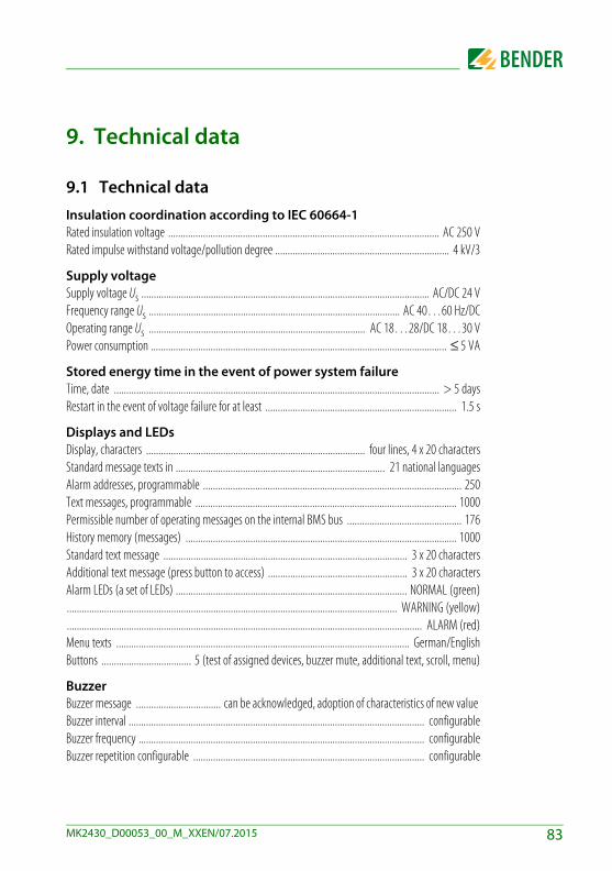
9. Technical data
9.1 Technical data
Insulation coordination according to IEC 60664-1 Rated insulation voltage ............................................................................................................. AC 250 VRated impulse withstand voltage/pollution degree ...................................................................... 4 kV/3
Supply voltageSupply voltage Us .................................................................................................................... AC/DC 24 VFrequency range Us ..................................................................................................... AC 40…60 Hz/DCOperating range Us ....................................................................................... AC 18…28/DC 18…30 VPower consumption ....................................................................................................................... ≤ 5 VA
Stored energy time in the event of power system failureTime, date ................................................................................................................................... > 5 daysRestart in the event of voltage failure for at least ............................................................................. 1.5 s
Displays and LEDsDisplay, characters ........................................................................................ four lines, 4 x 20 charactersStandard message texts in .................................................................................... 21 national languagesAlarm addresses, programmable ........................................................................................................ 250Text messages, programmable ......................................................................................................... 1000Permissible number of operating messages on the internal BMS bus .............................................. 176History memory (messages) ............................................................................................................. 1000Standard text message .................................................................................................. 3 x 20 charactersAdditional text message (press button to access) ........................................................ 3 x 20 charactersAlarm LEDs (a set of LEDs) ............................................................................................. NORMAL (green)..................................................................................................................................... WARNING (yellow)............................................................................................................................................... ALARM (red)Menu texts ...................................................................................................................... German/EnglishButtons .................................... 5 (test of assigned devices, buzzer mute, additional text, scroll, menu)
BuzzerBuzzer message .................................. can be acknowledged, adoption of characteristics of new value Buzzer interval ....................................................................................................................... configurableBuzzer frequency ................................................................................................................... configurableBuzzer repetition configurable ............................................................................................. configurable
83MK2430_D00053_00_M_XXEN/07.2015
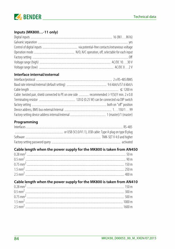
Technical data
Inputs (MK800…-11 only)Digital inputs ................................................................................................................... 16 (IN1…IN16)Galvanic separation .............................................................................................................................. yesControl of digital inputs ................................................. via potential-free contacts/extraneous voltageOperation mode ......................................................... N/O, N/C operation, off, selectable for each inputFactory setting ....................................................................................................................................... Off Voltage range (high) .................................................................................................... AC/DC 10…30 VVoltage range (low) ......................................................................................................... AC/DC 0…2 V
Interface internal/externalInterface/protocol ........................................................................................................... 2 x RS-485/BMSBaud rate internal/external (default setting) ........................................................ 9.6 kbit/s/57.6 kbit/sCable length ............................................................................................................................. ≤ 1200 mCable: twisted pair, shield connected to PE on one side .............. recommended: J-Y(St)Y min. 2 x 0.8Terminating resistor ................................................... 120 Ω (0.25 W) can be connected via DIP switchfactory setting ......................................................................................................... both on "off" positionDevice address, BMS bus external/internal .................................................................. 1…150/1…99Factory setting device address internal/external .................................................. 1 (master)/1 (master)
ProgrammingInterfaces ........................................................................................................................................ RS-485 .................................................................... or USB (V2.0/V1.1), USB cable: Type A plug on type B plug
Software .......................................................................................................... TMK-SET V 4.0 and higherFactory setting password query ................................................................................................. activated
Cable length when the power supply for the MK800 is taken from AN4500.28 mm2 ........................................................................................................................................... 50 m0.5 mm2 ............................................................................................................................................. 90 m0.75 mm2 ......................................................................................................................................... 150 m1.5 mm2 ........................................................................................................................................... 250 m2.5 mm2 ........................................................................................................................................... 400 m
Cable length when the power supply for the MK800 is taken from AN4100.28 mm2 ......................................................................................................................................... 150 m0.5 mm2 ........................................................................................................................................... 300 m0.75 mm2 ......................................................................................................................................... 500 m1.5 mm2 ......................................................................................................................................... 1000 m2.5 mm2 ......................................................................................................................................... 1600 m
84 MK2430_D00053_00_M_XXEN/07.2015
Technical data
ColoursFront foil ........................................................................ RAL 7035 (light grey) / RAL 7040 (basalt grey)Marking ................................................................................................................ RAL 5005 (signal blue)Front plate ............................................................................................................... RAL 7035 (light grey)
Switching elements (MK800-11 only)Number ................................................................................................................... 1 changeover contactFunction ............................................................................................................................ programmableOperation mode ......................................................................... N/C or N/O operation (programmable)Electrical service life under rated operating conditions ............................. 10,000 switching operationsContact data acc. to IEC 60947-5-1:Utilisation category ............................................................................................ AC-13 AC-14 DC-12Rated operational voltage ................................................................................... 24 V 24 V 24 V Rated operational current ..................................................................................... 5 A 3 A 1 AMinimum contact rating ...................................................................................... 1 mA at AC/DC > 10 V
Environment/EMC EMC immunity ........................................................................................................ acc. to EN 61000-6-2EMC emission .......................................................................................................... acc. to EN 61000-6-3Ambient temperatures:Operating temperature ........................................................................................................ -5…+55 °CTransport ............................................................................................................................ -25…+70 °CLong-term storage ............................................................................................................. -25…+55 °CClassification of climatic conditions acc. to IEC 60721:Stationary use (IEC 60721-3-3) ......................................... 3K5 (no condensation, no formation of ice)Transport (IEC 60721-3-2) .................................................................................................................. 2K3Long-term storage (IEC 60721-3-1) ................................................................................................... 1K4Classification of mechanical conditions acc. to IEC 60721:Stationary use (IEC 60721-3-3) ........................................................................................................ 3M4Transport (IEC 60721-3-2) ................................................................................................................ 2M2Long-term storage (IEC 60721-3-1) ................................................................................................. 1M3
Option "W" data different from the standard versionClassification of climatic conditions acc. to IEC 60721:Stationary use (IEC 60721-3-3) ............................ 3K5 (condensation and formation of ice is possible)Classification of mechanical conditions acc. to IEC 60721:Stationary use (IEC 60721-3-3) ........................................................................................................ 3M7
85MK2430_D00053_00_M_XXEN/07.2015

Technical data
ConnectionConnection ...................................................................................................... pluggable screw terminalsConnection properties (supply voltage, BMS bus):Rigid/flexible/conductor sizes .................................................. 0.2…2.5/0.2…2.5 mm2/AWG 24-12Flexible with ferrules, without/with plastic sleeve .................................. 0.25…2.5/0.25…2.5 mm2
Connection properties (inputs):Rigid/flexible/conductor sizes ............................................ 0.08…1.5/0.08…1.5 mm2/ AWG 28-16Flexible with ferrules, without/with plastic sleeve .................................. 0.25…1.5/0.25…0.5 mm2
Stripping length ................................................................................................................................ 7 mmTightening torque .................................................................................. 0.5…0.6 Nm (4.5…5.3 lb-in)
OtherOperation mode ...................................................................................................... continuous operationMounting ........................................................................................................................ display-orientedDegree of protection, built-in components (DIN EN 60529) ............................................................ IP50Degree of protection, terminals (DIN EN 60529) ............................................................................... IP20Flammability class ..................................................................................................................... UL94 V-0Weight:Flush-mounting/cavity wall (MK800) ......................................................................................... ≤ 950 gSurface-mounting (MK800A) ...................................................................................................... ≤ 880 gSurface-mounting (MK800AF) .................................................................................................. ≤ 1150 g
86 MK2430_D00053_00_M_XXEN/07.2015

Technical data
9.1.1 Standards, approvals and certificationsThe MK800 alarm indicator and test combination meets the requirements of the stand-ards DIN VDE 0100-710 (VDE 0100-710) and IEC 60364-7-710.
9.2 Ordering information
Type Description Art. No.
MK800-11 Alarm indicator and test combination acc. to DIN VDE 0100-710,with BMS bus and USB interface, 16 digital inputs, one relay output, alarm texts programmable via interfaces and personal computer, standard text display,Version: Flush-mounting enclosure; Menu languages German/English.
B 9510 0100
MK800-12 Alarm indicator and test combination acc. to DIN VDE 0100-710,with BMS bus and USB interface,alarm texts programmable via interfaces and personal computer, standard text display, version: Flush-mounting enclosure; Menu languages: German/English
B 9510 0101
MK800A-11 As MK800-11, but with surface-mounting enclosure. B 9510 0102
MK800A-12 As MK800-12, but with surface-mounting enclosure. B 9510 0103
MK800AF-11
As MK800-11, but with surface-mounting enclosure with front door.
B 9510 0104
MK800AF-12
As MK800-12, but with surface-mounting enclosure with front door.
B 9510 0105
MK800E-11 As MK800-11, but as built-in type without enclosure. B 9510 0106
MK800E-12 As MK800-12, but as built-in type without enclosure. B 9510 0107
87MK2430_D00053_00_M_XXEN/07.2015

Technical data
UP800 Flush-mounting enclosure for MK800 B 9510 0110
BR800-1 Bezel frame silver for MK800 B 9510 0111
BR800-2 Bezel frame white for MK800 B 9510 0112
Parameteri-sation software
- TMK-SET V 4.x parameterisation software for MK2430, MK800, TM800,- TMK-History V 3.x for MK2430, MK800, TM800, TM1000 and PRC1470- USB driver software for MK2430, MK800 and TM800- MEDISET V1.x parameterisation software for TM1000 and PRC1470
by Internetdownload
Type Description Art. No.
88 MK2430_D00053_00_M_XXEN/07.2015
INDEX
AAccident prevention 11Acknowledgement 69Acknowledgements 61Additional text 52Address settings 32Alarm
- Repetition 15Alarm addresses 16, 64Alarm indicator and operator panel 18Alarm message 14, 16
- neutral 67- specific 67
Alarm relay 47, 73Assignments 79Automatic mode 76
BBaud rate 72Beep code 47Bender service personnel 74BMS bus
- internal 18BMS bus address 72Buzzer
- Audio frequency 69- Reminder 68
CCable length 27Cable lengths 27Cavity wall mounting 20Changeover periods 43Characteristics 15Clear text display 9
Commissioning 37Commissioning pattern 37Common acknowledgement 69Connection 27Control 75Control panel mounting
- with enclosure 22
DDate 70Date format 70Device address 72Diagram 59Digital inputs 67digital inputs 29Dimensions 11Display 16Display and operating units 14Display functions 9Displaying information 77Disturbances 11
Eelectrostatic electricity 26ENTER button 52Equipment failures 14Error list 49Errors 47Evaluating devices 77Example 14External devices 77
FFault
- condition 53
89MK2430_D00053_00_M_XXEN/07.2015

INDEX
Firmware version 57, 79Flush-mounting enclosure 20Front panel 21Functional test 43Functionality 14
GGases
- medical 9, 68Gateways 14
HHistory memory 17, 18, 61
- read out 17
IIndication
- audible 9- visual 9
Individual alarm texts 65Inputs
- digital 14, 17, 27, 67Installation documentation 37Intended use 9Interface 17, 72interface 17
LLanguage 71LEDs 16Liability 7
MMain menu 58Master 18Master clock 18Measurement addresses 66medical gases 68
MEDICS® 13Menu mode 58Message text display 62Message texts 15, 17MK800-11 17MK800-12 17Monitoring modules 14
NNational languages 15, 16Navigation 59Normal
- operating conditions 53
OOffice buildings 10Operation 51Ordering information 87
PPanel mounting
- without enclosure 21Parallel indication 14, 17Parameter setting 15Parameterisation 39Parameters 80Password 58, 74Periodic verification 43Personnel 10Plain text 14Planer 7potential free contacts 17potential-free contacts 29Protocol converters 14
QQuick reference guide 51
90 MK2430_D00053_00_M_XXEN/07.2015
INDEX
RRelay mode 73Relay output 27, 29, 30Relay outputs 14Replacement parts 11Reset 75Reset mode 77Risks 11
SScroll 52Selective operation 11Service menu 74Setting possibilities 80Setting values 43Settings 18, 39, 40, 41, 63Shape stability 20Single mode 76Slave 18Software 16, 18Standard display 57Standards 87Starting procedure 57Starting the EDS system 76Status information 16Status line 54, 55Summertime 70Surface-mounting enclosure 24, 25Switching on 38, 39System components 7System number 65
TTerminating resistor 29, 31Terminating resistor
27Termination of the BMS bus 30TEST 52Test 55
- Error code 55- Error code note 56
Test addresses 65Test communication 76Test intervals 10Test procedure 76Tests 37Text display 16Text messages 17Time 70
- entire system 70- synchronise 18
TMK HISTORY 18, 61TMK-SET 18, 39, 41, 64, 67, 68Transfer rate 72
UUSB cable 18USB interface 18Use
- intended 10
VValue addresses 66
WWarranty 11Wiring diagram 26
91MK2430_D00053_00_M_XXEN/07.2015

92 MK2430_D00053_00_M_XXEN/07.2015


Photos: Bender archives.
Bender GmbH & Co. KGP.O. Box 1161 • 35301 Gruenberg • GermanyLondorfer Straße 65 • 35305 Gruenberg • GermanyTel.: +49 6401 807-0 • Fax: +49 6401 807-259E-mail: [email protected] • www.bender.de
BENDER Group