Embed Size (px)
Citation preview
95C-10753-02
ML7984 Valve Actuator
PRODUCT DATA
APPLICATIONThe ML7984 is a self-contained, self-adjusting, linear motor-ized linkage that mounts directly onto V5011 two-way or V5013 three-way valves and provides up to 19 mm (3/4”) of linear travel (stem lift). For use with Series 70 2-10Vdc, 4-20mA electronic and Series 90 135 Ω, Electronic (Super Mod) modulating signal controllers.
FEATURESThe ML7984 valve actuator provides the following features:
• Allows the use of one common transformer power supply for multiple actuators and controllers
• Field-configurable DIP switches for Series 70 / 90 control-ler
• Field-configurable DIP switches for Direct / Reverse action• Field-selectable terminals for 2-10Vdc / 4-20 mA signal
input• One device for either Vac or Vdc power supply application• Compatible with 3 -wire system (one common wire for
both signal & power inputs)
• Separate models available for V5011/13 A and C or V5011/13 F and G valve body types
• Self-contained, motorized valve linkage.• Linkage self-adjusts to valve stroke of up to 19 mm (3/4”)• Multipoise mounting• Strong valve seat closing force 710 Newton (160 lbs.)• Compact size for easy installation in confined areas• Electronic current sensing provides internal protection and
positive full closing force• Field-addable auxiliary switches available
SPECIFICATIONS
Ambient RatingOperating Temperature: 0°C to 55°C (32°F to 130°F)
Shipping Temperature: -40°C to +65°C (-40°F to 150°F)
Relative Humidity: 15% to 95% at 40°C (104°F)
Acoustic Noise55 dBA max. Sound Pressure Level at 1 m (39”) distance.
Electrical RatingsPower supply/consumption: 24V (Nominal), 50/60Hz or 24 to 28 Vdc. 6VA(Running), 12VA(Valve seating)
Input ImpedanceVoltage Model -- 20 KΩ
Current Model --237 Ω
Shipping WeightApprox. 1 kg (2.2 lbs)
ML7984 VaLVe actuator
95C-10753—02 2
Accessories/Parts272630A: Auxiliary switch assembly (1-SPDT)
272630B: Auxiliary switch assembly (2-SPDT)
40003793-003: Mounting hardware bag assembly
272822: Resistor kit for multiple Series 90 application and for ML7984 to replace the old ML784 (4-20 mA)
Mechanical RatingsStroke: 19mm (3/4”) or less
Stroke timing: Approx. 63 seconds for 3/4” stroke
Closing Force: 710N (160 lbs.) Nominal*
*Rating applies to both directions.
Performance SpecificationsLife Expectancy (at rated load and power conditions): 50,000 full stroke cycles plus 1,000,000 repositions at 10% stem travel or 10 years, whichever occurs first.
NOTE: Rapid repositioning will result in reduced service life of the actuator.
INSTALLATION
CAUTIONEquipment Damage Hazard.Installer must be a trained service technician.Do not electrically operate the ML7984 before assembly to the valve because damage not ap-parent to the installer may occur.
Mounting1. Ensure that the valve body is installed correctly, that is,
the arrow points in the direction of the flow.2. Although the actuator can be mounted in any position,
it is preferable that the ML7984 is mounted above the valve body. This will minimize the risk of damage to the ML7984 in the event of condensation or a valve gland leak.
3. Remove the stem button (Fig 3) from the valve stem. Save the set screw inside the stem button for later installation. The button itself is not needed.
4. Slide the position indicator (plastic disk or rubber O-ring) over the valve stem. (See inset, Fig 3) Indica-tor will selfalign to the marking on the yoke after one complete operating cycle.
4(102) 3 - 1 3 / 6 4
( 8 2)
3 -1 /16( 7 8)
1/4 – 20 NUT [2]
1-3 /8 (35)MOUNTINGDIA.
3 /4(19) NOMINAL
STROKE
7/8 (22)KNOCKOUT
M32553
25/32(20)
4-1 /16(103)
1 - 1 7 / 3 2( 3 9 )
2 ( 5 1 )
4 - 1 / 6 4( 1 0 2 )
1/4 – 28UNF
51/64(21)
2-3 /32(53)
17/64(7)
25/64(10)13 /64
(6 ) 3 / 1 6 ( 5 ) DIA.3-7 /32 (82)
2-13/64 (56)
1-21/32(42)
3-3 /32(78)
7-3 /64(179)
4-9 /16(116)
2-23/32 (69)YELLOW
2-53/64 (72) SILVER
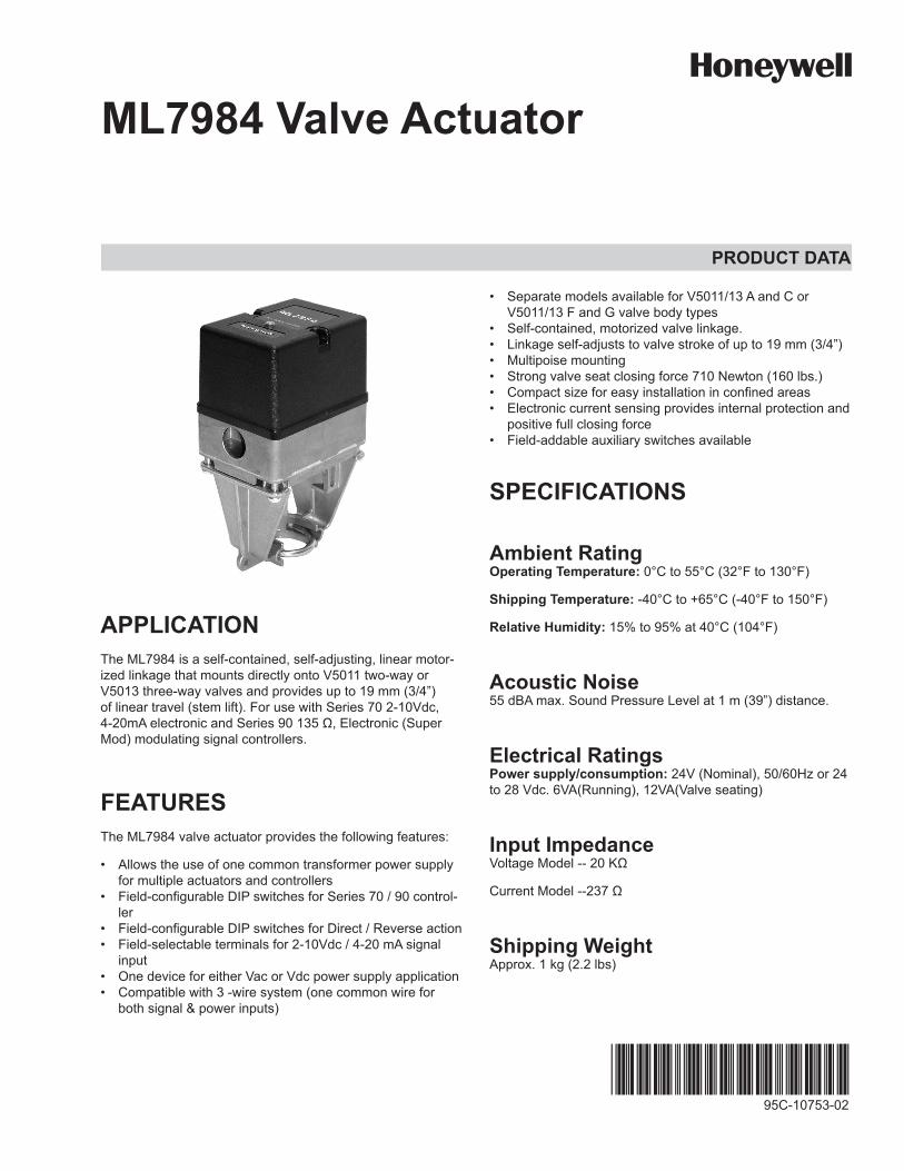
Fig 1. Dimesions of ML7984 valve actuator in mm (in.).
ML7984 VaLVe actuator
3 95C-10753—02
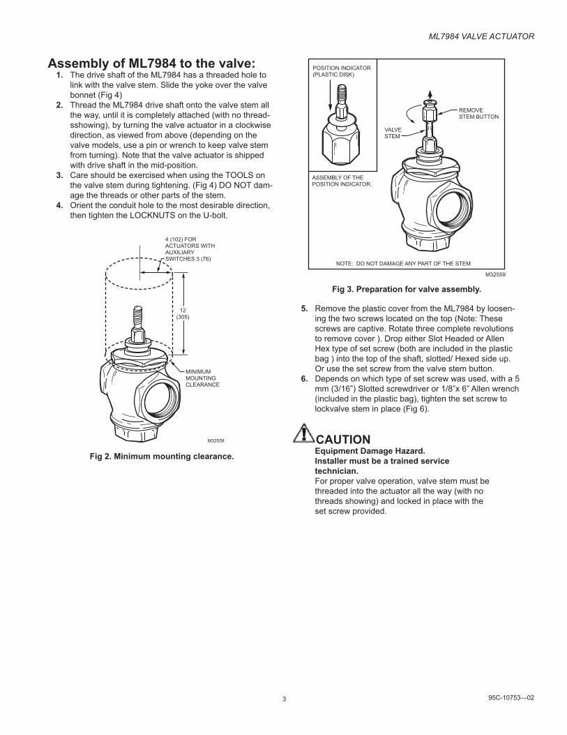
Assembly of ML7984 to the valve:1. The drive shaft of the ML7984 has a threaded hole to
link with the valve stem. Slide the yoke over the valve bonnet (Fig 4)
2. Thread the ML7984 drive shaft onto the valve stem all the way, until it is completely attached (with no thread-sshowing), by turning the valve actuator in a clockwise direction, as viewed from above (depending on the valve models, use a pin or wrench to keep valve stem from turning). Note that the valve actuator is shipped with drive shaft in the mid-position.
3. Care should be exercised when using the TOOLS on the valve stem during tightening. (Fig 4) DO NOT dam-age the threads or other parts of the stem.
4. Orient the conduit hole to the most desirable direction, then tighten the LOCKNUTS on the U-bolt.
MINIMUMMOUNTINGCLEARANCE
12(305)
4 (102) FOR ACTUATORS WITH AUXILIARY SWITCHES 3 (76)
M32558
Fig 2. Minimum mounting clearance.
ASSEMBLY OF THEPOSITION INDICATOR.
POSITION INDICATOR(PLASTIC DISK)
VALVESTEM
NOTE: DO NOT DAMAGE ANY PART OF THE STEM
REMOVESTEM BUTTON
M32559
Fig 3. Preparation for valve assembly.
5. Remove the plastic cover from the ML7984 by loosen-ing the two screws located on the top (Note: These screws are captive. Rotate three complete revolutions to remove cover ). Drop either Slot Headed or Allen Hex type of set screw (both are included in the plastic bag ) into the top of the shaft, slotted/ Hexed side up. Or use the set screw from the valve stem button.
6. Depends on which type of set screw was used, with a 5 mm (3/16”) Slotted screwdriver or 1/8”x 6” Allen wrench (included in the plastic bag), tighten the set screw to lockvalve stem in place (Fig 6).
CAUTIONEquipment Damage Hazard.Installer must be a trained service technician.For proper valve operation, valve stem must be threaded into the actuator all the way (with no threads showing) and locked in place with the set screw provided.
ML7984 VaLVe actuator
95C-10753—02 4
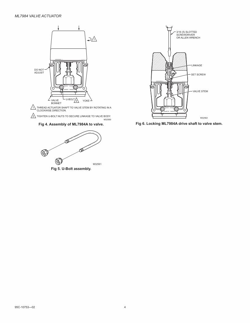
M32560
VALVEBONNET
U-BOLT YOKE
THREAD ACTUATOR SHAFT TO VALVE STEM BY ROTATING IN A CLOCKWISE DIRECTION.
TIGHTEN U-BOLT NUTS TO SECURE LINKAGE TO VALVE BODY.
1
2
2
1
DO NOTADJUST
Fig 4. Assembly of ML7984A to valve.
M32561
Fig 5. U-Bolt assembly.
M32562
3/16 (5) SLOTTED SCREWDRIVER OR ALLEN WRENCH
LINKAGE
SET SCREW
VALVE STEM
Fig 6. Locking ML7984A drive shaft to valve stem.
ML7984 VaLVe actuator
5 95C-10753—02
SIGNALSOURCE
(VDC) ML7984
ML7984
ML7984
24 VACL1
OR
28 VDC
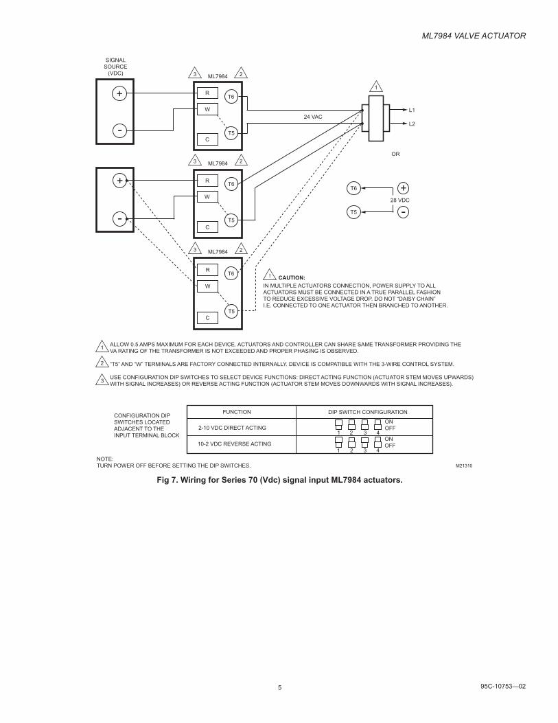
IN MULTIPLE ACTUATORS CONNECTION, POWER SUPPLY TO ALLACTUATORS MUST BE CONNECTED IN A TRUE PARALLEL FASHIONTO REDUCE EXCESSIVE VOLTAGE DROP. DO NOT “DAISY CHAIN” I.E. CONNECTED TO ONE ACTUATOR THEN BRANCHED TO ANOTHER.
CAUTION:
ALLOW 0.5 AMPS MAXIMUM FOR EACH DEVICE. ACTUATORS AND CONTROLLER CAN SHARE SAME TRANSFORMER PROVIDING THEVA RATING OF THE TRANSFORMER IS NOT EXCEEDED AND PROPER PHASING IS OBSERVED.
“T5” AND “W” TERMINALS ARE FACTORY CONNECTED INTERNALLY. DEVICE IS COMPATIBLE WITH THE 3-WIRE CONTROL SYSTEM.
USE CONFIGURATION DIP SWITCHES TO SELECT DEVICE FUNCTIONS: DIRECT ACTING FUNCTION (ACTUATOR STEM MOVES UPWARDS)WITH SIGNAL INCREASES) OR REVERSE ACTING FUNCTION (ACTUATOR STEM MOVES DOWNWARDS WITH SIGNAL INCREASES).
CONFIGURATION DIPSWITCHES LOCATEDADJACENT TO THE INPUT TERMINAL BLOCK
NOTE:TURN POWER OFF BEFORE SETTING THE DIP SWITCHES.
FUNCTION DIP SWITCH CONFIGURATION
2-10 VDC DIRECT ACTING
10-2 VDC REVERSE ACTING
ONOFF
ONOFF
+
-
++
- -
T6
T5
L2
1
1
2
3
3 2
R
W
C
T6
T5
3 2
R
W
C
T6
T5
3 2
R
W
C
T6
T5
!
1 2 3 4
1 2 3 4
M21310
Fig 7. Wiring for Series 70 (Vdc) signal input ML7984 actuators.
ML7984 VaLVe actuator
95C-10753—02 6
SIGNALSOURCE
(mA) ML7984
ML7984(MASTER)
ML7984(SLAVE)
24 VACL1
OR
28 VDC
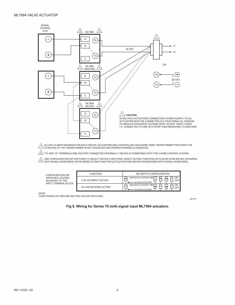
IN MULTIPLE ACTUATORS CONNECTION, POWER SUPPLY TO ALLACTUATORS MUST BE CONNECTED IN A TRUE PARALLEL FASHIONTO REDUCE EXCESSIVE VOLTAGE DROP. DO NOT “DAISY CHAIN” I.E. CONNECTED TO ONE ACTUATOR THEN BRANCHED TO ANOTHER.
CAUTION:
ALLOW 0.5 AMPS MAXIMUM FOR EACH DEVICE. ACTUATORS AND CONTROLLER CAN SHARE SAME TRANSFORMER PROVIDING THEVA RATING OF THE TRANSFORMER IS NOT EXCEEDED AND PROPER PHASING IS OBSERVED.
“T5” AND “W” TERMINALS ARE FACTORY CONNECTED INTERNALLY. DEVICE IS COMPATIBLE WITH THE 3-WIRE CONTROL SYSTEM.
USE CONFIGURATION DIP SWITCHES TO SELECT DEVICE FUNCTIONS: DIRECT ACTING FUNCTION (ACTUATOR STEM MOVES UPWARDS)WITH SIGNAL INCREASES) OR REVERSE ACTING FUNCTION (ACTUATOR STEM MOVES DOWNWARDS WITH SIGNAL INCREASES).
CONFIGURATION DIPSWITCHES LOCATEDADJACENT TO THE INPUT TERMINAL BLOCK
NOTE:TURN POWER OFF BEFORE SETTING THE DIP SWITCHES.
FUNCTION DIP SWITCH CONFIGURATION
4-20 mA DIRECT ACTING
20-4 MA REVERSE ACTING
ONOFF
ONOFF
+
-
+
+--
T6
T5
L2
1
1
2
3
3 2
R
W
C
T6
T5
3 2
R
W
C
T6
T5
3 2
R
W
C
T6
T5
!
1 2 3 4
1 2 3 4
M21311
1
1
MASTER ACTUATOR
SLAVE ACTUATORMASTER ACTUATOR
SLAVE ACTUATOR
Fig 8. Wiring for Series 70 (mA) signal input ML7984 actuators.
ML7984 VaLVe actuator
7 95C-10753—02
SIGNALSOURCE
(135 OHM) ML7984
ML7984
ML7984
24 VACL1
OR
28 VDC
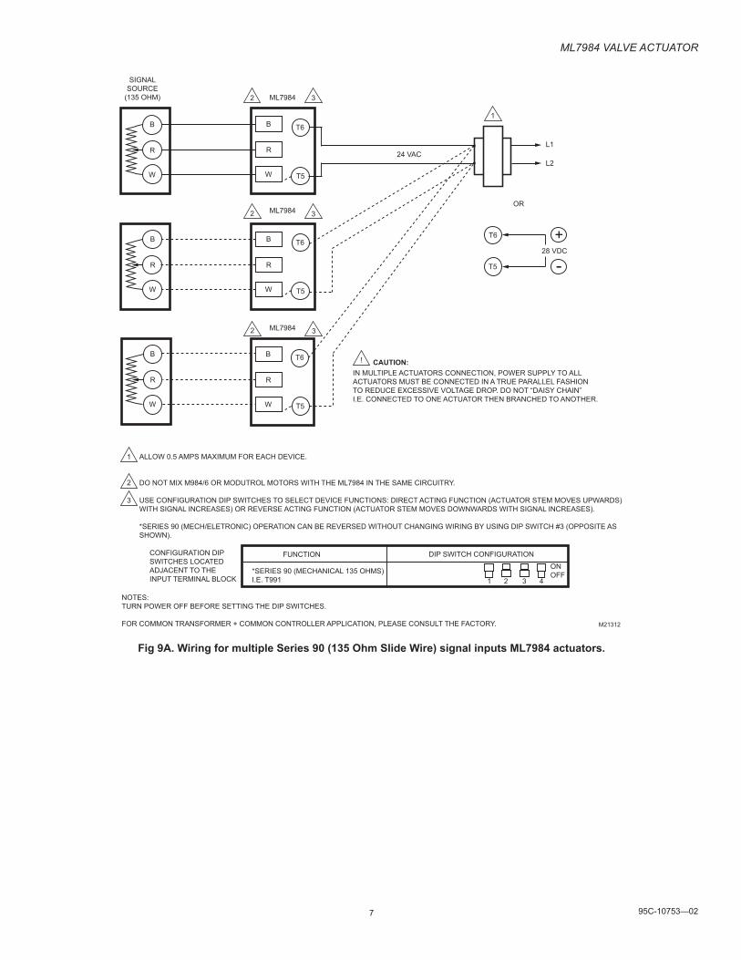
IN MULTIPLE ACTUATORS CONNECTION, POWER SUPPLY TO ALLACTUATORS MUST BE CONNECTED IN A TRUE PARALLEL FASHIONTO REDUCE EXCESSIVE VOLTAGE DROP. DO NOT “DAISY CHAIN” I.E. CONNECTED TO ONE ACTUATOR THEN BRANCHED TO ANOTHER.
CAUTION:
ALLOW 0.5 AMPS MAXIMUM FOR EACH DEVICE.
DO NOT MIX M984/6 OR MODUTROL MOTORS WITH THE ML7984 IN THE SAME CIRCUITRY.
USE CONFIGURATION DIP SWITCHES TO SELECT DEVICE FUNCTIONS: DIRECT ACTING FUNCTION (ACTUATOR STEM MOVES UPWARDS)WITH SIGNAL INCREASES) OR REVERSE ACTING FUNCTION (ACTUATOR STEM MOVES DOWNWARDS WITH SIGNAL INCREASES).
*SERIES 90 (MECH/ELETRONIC) OPERATION CAN BE REVERSED WITHOUT CHANGING WIRING BY USING DIP SWITCH #3 (OPPOSITE ASSHOWN).
CONFIGURATION DIPSWITCHES LOCATEDADJACENT TO THE INPUT TERMINAL BLOCK
NOTES:TURN POWER OFF BEFORE SETTING THE DIP SWITCHES.
FOR COMMON TRANSFORMER + COMMON CONTROLLER APPLICATION, PLEASE CONSULT THE FACTORY.
FUNCTION DIP SWITCH CONFIGURATION
*SERIES 90 (MECHANICAL 135 OHMS)I.E. T991
ONOFF
+
-
T6
T5
L2
1
1
2
3
2 3
B
R
W
T6
T5
2 3
2 3
!
1 2 3 4
M21312
B
R
W
B
R
W
B
R
W
B
R
W
T6
T5
B
R
W
T6
T5
Fig 9A. Wiring for multiple Series 90 (135 Ohm Slide Wire) signal inputs ML7984 actuators.
ML7984 VaLVe actuator
95C-10753—02 8
SIGNALSOURCE
(135 OHM) ML7984
ML7984
ML7984
24 VACL1
OR
28 VDC
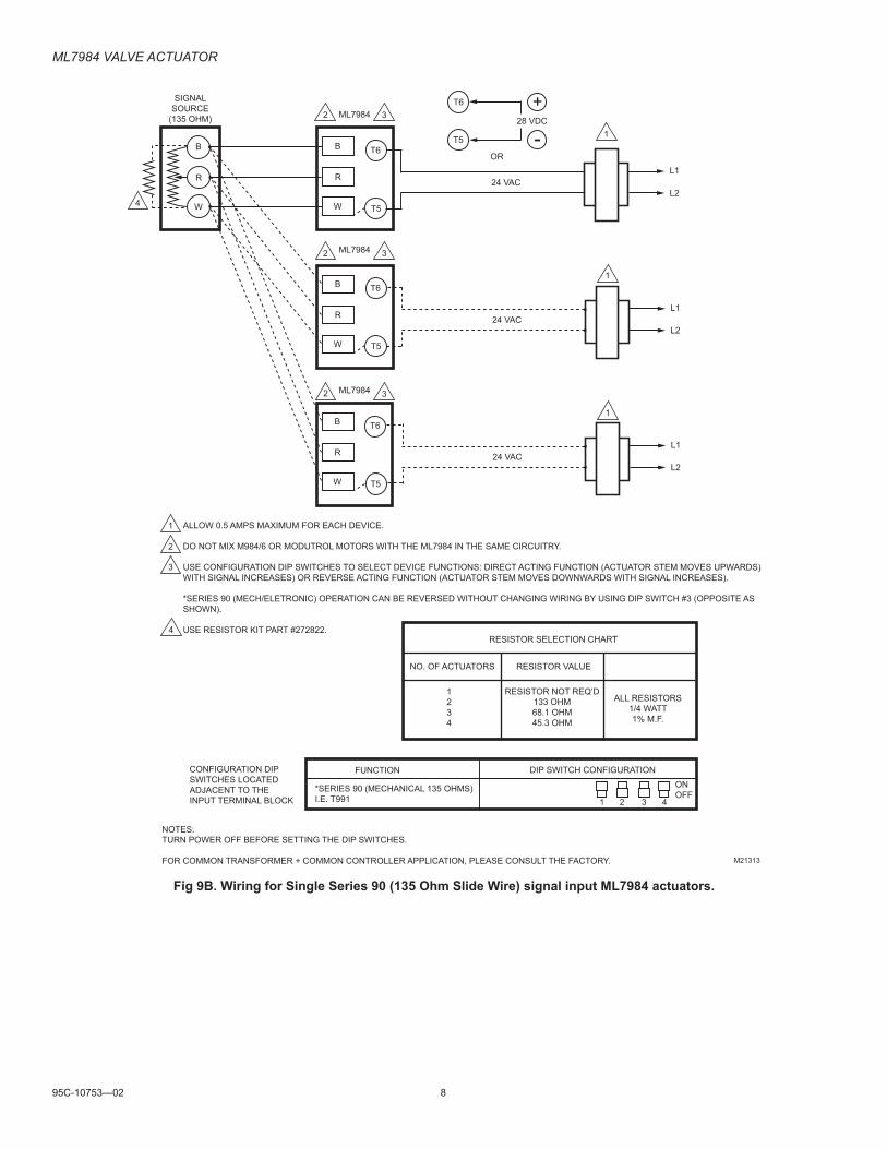
ALLOW 0.5 AMPS MAXIMUM FOR EACH DEVICE.
DO NOT MIX M984/6 OR MODUTROL MOTORS WITH THE ML7984 IN THE SAME CIRCUITRY.
USE CONFIGURATION DIP SWITCHES TO SELECT DEVICE FUNCTIONS: DIRECT ACTING FUNCTION (ACTUATOR STEM MOVES UPWARDS)WITH SIGNAL INCREASES) OR REVERSE ACTING FUNCTION (ACTUATOR STEM MOVES DOWNWARDS WITH SIGNAL INCREASES).
*SERIES 90 (MECH/ELETRONIC) OPERATION CAN BE REVERSED WITHOUT CHANGING WIRING BY USING DIP SWITCH #3 (OPPOSITE ASSHOWN).
USE RESISTOR KIT PART #272822.
CONFIGURATION DIPSWITCHES LOCATEDADJACENT TO THE INPUT TERMINAL BLOCK
NOTES:TURN POWER OFF BEFORE SETTING THE DIP SWITCHES.
FOR COMMON TRANSFORMER + COMMON CONTROLLER APPLICATION, PLEASE CONSULT THE FACTORY.
FUNCTION DIP SWITCH CONFIGURATION
*SERIES 90 (MECHANICAL 135 OHMS)I.E. T991
ONOFF
+
-
T6
T5
L2
1
1
2
3
2 3
B
R
W
T6
T5
2 3
2 3
1 2 3 4
M21313
B
R
W
B
R
W
T6
T5
B
R
W
T6
T5
4
24 VACL1
L2
24 VACL1
L2
1
1
4RESISTOR SELECTION CHART
NO. OF ACTUATORS RESISTOR VALUE
1234
RESISTOR NOT REQ’D133 OHM68.1 OHM45.3 OHM
ALL RESISTORS1/4 WATT1% M.F.
Fig 9B. Wiring for Single Series 90 (135 Ohm Slide Wire) signal input ML7984 actuators.
ML7984 VaLVe actuator
9 95C-10753—02
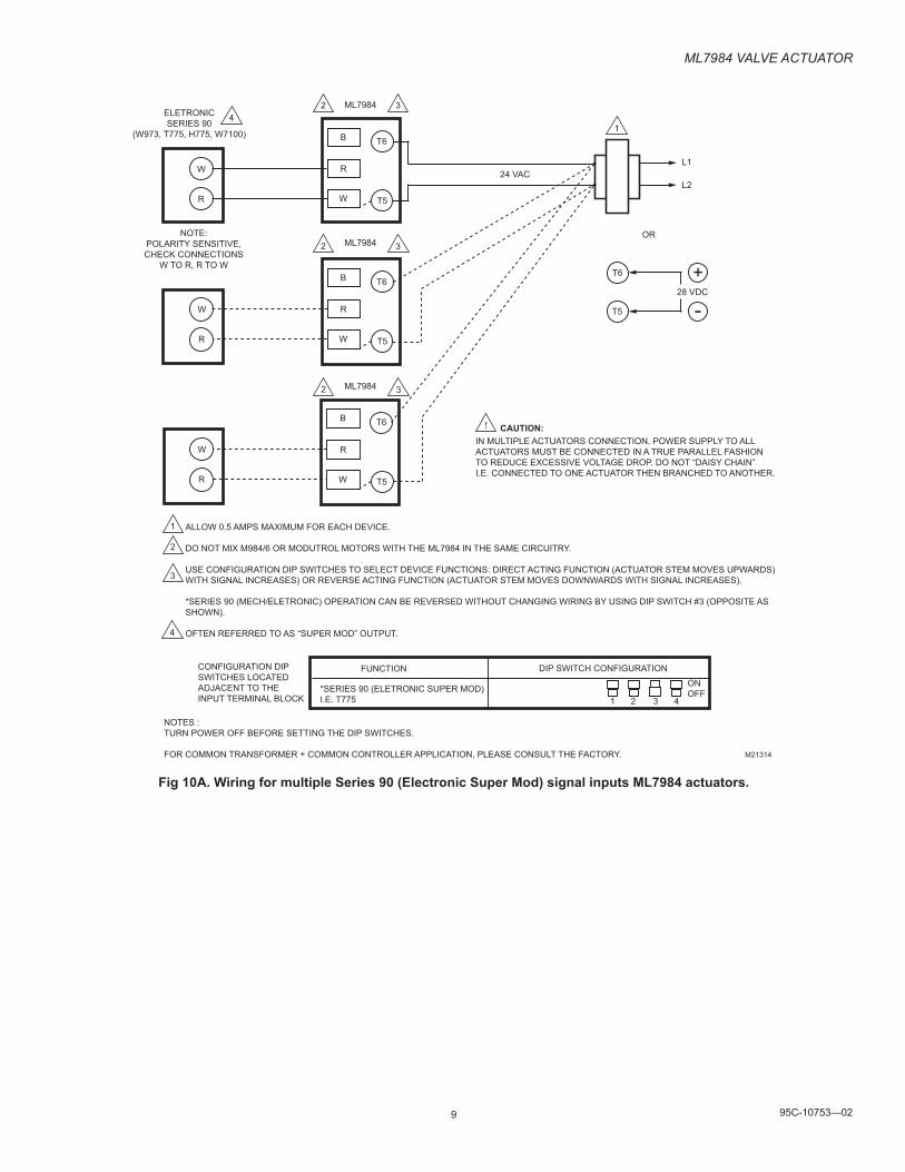
ELETRONICSERIES 90
(W973, T775, H775, W7100)
ML7984
ML7984
ML7984
24 VACL1
OR
28 VDC
IN MULTIPLE ACTUATORS CONNECTION, POWER SUPPLY TO ALLACTUATORS MUST BE CONNECTED IN A TRUE PARALLEL FASHIONTO REDUCE EXCESSIVE VOLTAGE DROP. DO NOT “DAISY CHAIN” I.E. CONNECTED TO ONE ACTUATOR THEN BRANCHED TO ANOTHER.
CAUTION:
ALLOW 0.5 AMPS MAXIMUM FOR EACH DEVICE.
DO NOT MIX M984/6 OR MODUTROL MOTORS WITH THE ML7984 IN THE SAME CIRCUITRY.
USE CONFIGURATION DIP SWITCHES TO SELECT DEVICE FUNCTIONS: DIRECT ACTING FUNCTION (ACTUATOR STEM MOVES UPWARDS)WITH SIGNAL INCREASES) OR REVERSE ACTING FUNCTION (ACTUATOR STEM MOVES DOWNWARDS WITH SIGNAL INCREASES).
*SERIES 90 (MECH/ELETRONIC) OPERATION CAN BE REVERSED WITHOUT CHANGING WIRING BY USING DIP SWITCH #3 (OPPOSITE ASSHOWN).
OFTEN REFERRED TO AS “SUPER MOD” OUTPUT.
CONFIGURATION DIPSWITCHES LOCATEDADJACENT TO THE INPUT TERMINAL BLOCK
NOTES :TURN POWER OFF BEFORE SETTING THE DIP SWITCHES.
FOR COMMON TRANSFORMER + COMMON CONTROLLER APPLICATION, PLEASE CONSULT THE FACTORY.
FUNCTION DIP SWITCH CONFIGURATION
*SERIES 90 (ELETRONIC SUPER MOD)I.E. T775
ONOFF
+
-
T6
T5
L2
1
1
2
3
2 3
B
R
W
T6
T5
2 3
2 3
!
1 2 3 4
M21314
W
R
W
R
W
R
B
R
W
T6
T5
B
R
W
T6
T5
4
4
NOTE:POLARITY SENSITIVE,CHECK CONNECTIONS
W TO R, R TO W
Fig 10A. Wiring for multiple Series 90 (Electronic Super Mod) signal inputs ML7984 actuators.
ML7984 VaLVe actuator
95C-10753—02 10
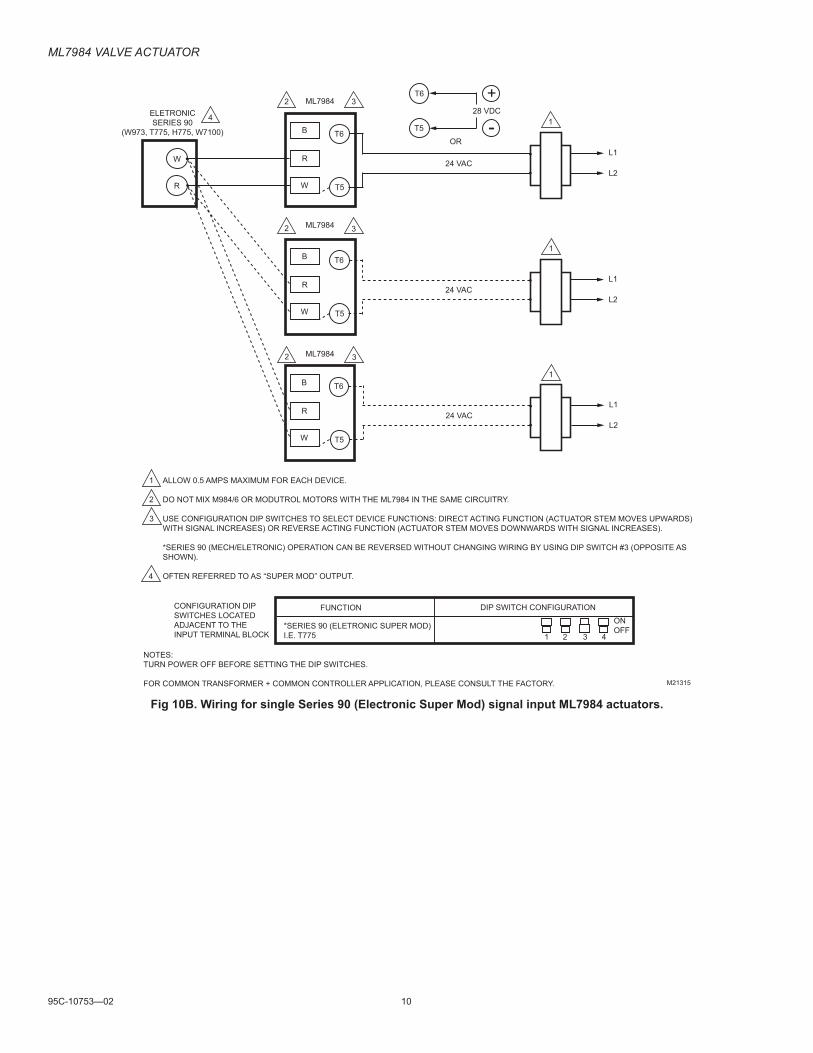
ELETRONICSERIES 90
(W973, T775, H775, W7100)
ML7984
ML7984
ML7984
24 VACL1
OR
28 VDC
ALLOW 0.5 AMPS MAXIMUM FOR EACH DEVICE.
DO NOT MIX M984/6 OR MODUTROL MOTORS WITH THE ML7984 IN THE SAME CIRCUITRY.
USE CONFIGURATION DIP SWITCHES TO SELECT DEVICE FUNCTIONS: DIRECT ACTING FUNCTION (ACTUATOR STEM MOVES UPWARDS)WITH SIGNAL INCREASES) OR REVERSE ACTING FUNCTION (ACTUATOR STEM MOVES DOWNWARDS WITH SIGNAL INCREASES).
*SERIES 90 (MECH/ELETRONIC) OPERATION CAN BE REVERSED WITHOUT CHANGING WIRING BY USING DIP SWITCH #3 (OPPOSITE ASSHOWN).
OFTEN REFERRED TO AS “SUPER MOD” OUTPUT.
CONFIGURATION DIPSWITCHES LOCATEDADJACENT TO THE INPUT TERMINAL BLOCK
NOTES:TURN POWER OFF BEFORE SETTING THE DIP SWITCHES.
FOR COMMON TRANSFORMER + COMMON CONTROLLER APPLICATION, PLEASE CONSULT THE FACTORY.
FUNCTION DIP SWITCH CONFIGURATION
*SERIES 90 (ELETRONIC SUPER MOD)I.E. T775
ONOFF
+
-
T6
T5
L2
1
1
2
3
2 3
B
R
W
T6
T5
2 3
2 3
1 2 3 4
M21315
W
R
B
R
W
T6
T5
B
R
W
T6
T5
4
4
24 VACL1
L2
24 VACL1
L2
1
1
Fig 10B. Wiring for single Series 90 (Electronic Super Mod) signal input ML7984 actuators.
ML7984 VaLVe actuator
11 95C-10753—02
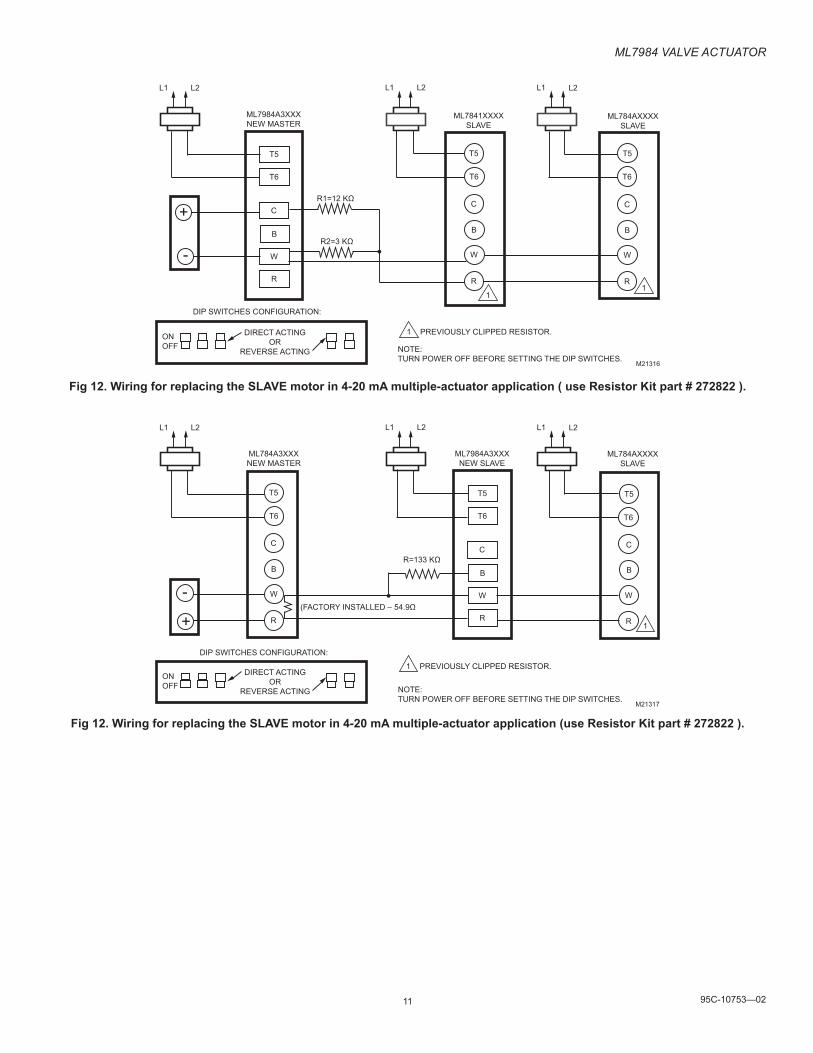
T6 T6
T5 T5
C
B
W
R
C
B
W
R
T5
T6
C
B
W
R
ONOFF
DIP SWITCHES CONFIGURATION:
NOTE:TURN POWER OFF BEFORE SETTING THE DIP SWITCHES.
ML7984A3XXXNEW MASTER
ML7841XXXXSLAVE
ML784AXXXXSLAVE
L1 L2 L2 L2L1 L1
R1=12 KΩ
R2=3 KΩ
+
-
DIRECT ACTINGOR
REVERSE ACTINGM21316
PREVIOUSLY CLIPPED RESISTOR.1
11
Fig 12. Wiring for replacing the SLAVE motor in 4-20 mA multiple-actuator application ( use Resistor Kit part # 272822 ).
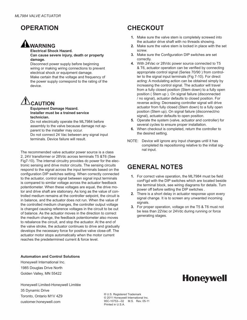
T6 T6
T5 T5
C
B
W
R
C
B
W
R
T5
T6
C
B
W
R
ONOFF
DIP SWITCHES CONFIGURATION:
NOTE:TURN POWER OFF BEFORE SETTING THE DIP SWITCHES.
ML784A3XXXNEW MASTER
ML7984A3XXXNEW SLAVE
ML784AXXXXSLAVE
L1 L2 L2 L2L1 L1
R=133 KΩ
+
-
DIRECT ACTINGOR
REVERSE ACTINGM21317
(FACTORY INSTALLED – 54.9Ω
PREVIOUSLY CLIPPED RESISTOR.1
1
Fig 12. Wiring for replacing the SLAVE motor in 4-20 mA multiple-actuator application (use Resistor Kit part # 272822 ).
ML7984 VaLVe actuator
Automation and Control SolutionsHoneywell International Inc.1985 Douglas Drive NorthGolden Valley, MN 55422
Honeywell Limited-Honeywell Limitée35 Dynamic DriveToronto, Ontario M1V 4Z9customer.honeywell.com
® U.S. Registered Trademark© 2011 Honeywell International Inc.95C-10753—02 M.S. Rev. 05-11Printed in U.S.A.
OPERATION
WARNINGElectrical Shock Hazard.Can cause severe injury, death or property damage.Disconnect power supply before beginning wiring or making wiring connections to prevent electrical shock or equipment damage.Make certain that the voltage and frequency of the power supply correspond to the rating of the device.
CAUTIONEquipment Damage Hazard.Installer must be a trained service technician.Do not electrically operate the ML7984 before assembly to the valve because damage not ap-parent to the installer may occur.Do not connect 24 Vac between any signal input terminals. Device failure will result.
The recommended valve actuator power source is a class 2, 24V transformer or 28Vdc across terminals T5 &T6 (See Fig7-10). The internal circuitry provides dc power for the elec-tronic sensing and drive motor circuits. The sensing circuits respond to the signal across the input terminals based on the configuration DIP switches setting. When correctly connected to the actuator, control signal between signal input terminals is compared to similar voltage across the actuator feedback potentiometer. When these voltages are equal, the drive mo-tor and drive shaft are stationary. As long as the value of con-trolled medium remains at the controller setpoint, the circuit is in balance, and the actuator does not run. When the value of the controlled medium changes, the controller output voltage is changed causing reference voltages in the circuit to be out of balance. As the actuator moves in the direction to correct the medium change, the feedback potentiometer also moves to rebalance the circuit, and stop the actuator. At the end of the valve stroke, the actuator continues to drive and gradually develops the necessary force for positive valve close-off. The actuator motor stops automatically when the motor current reaches the predetermined current & force level.
CHECKOUT1. Make sure the valve stem is completely screwed into
the actuator drive shaft with no threads showing.2. Make sure the valve stem is locked in place with the set
screw.3. Make sure the Configuration DIP switches are set
correctly.4. With 24Vac or 28Vdc power source connected to T5
& T6, actuator operation can be verified by connecting appropriate control signal (Series 70/90 ) from control-ler to the signal input terminals (Fig 7-10). For direct acting: A modulating action can be obtained simply by increasing the control signal. The actuator will travel from a fully closed position (Stem down) to a fully open position ( Stem up ). On signal failure (disconnected / no signal), actuator defaults to closed position. For reverse acting: Decreasing controller signal will drive actuator from fully closed (Stem down) to a fully open position (Stem up). On signal failure (disconnect/no signal), actuator defaults to open position.
5. Operate the system (valve, actuator and controller) for several cycles to ensure proper installation.
6. When checkout is completed, return the controller to the desired setting.
NOTE: Device will ignore any input changes until it has completed its repositioning relative to the initial sig-nal input.
GENERAL NOTES1. For correct valve operation, the ML7984 must be field
conFigd with the DIP switches which are located beside the terminal block, see wiring diagrams for details. Turn power off before setting the DIP switches .
2. There is a short delay in actuator response upon every signal change. It is to screen any unwanted incoming signals.
3. For proper operation, voltage on the T5 & T6 must not be less than 22Vac or 24Vdc during running or force generating stages.