Embed Size (px)
Citation preview

MAGUIRE PRODUCTS, INC.11 Crozerville RoadAston, PA 19014, USATel: + 1 610 459 4300 Fax: +1 610 459 [email protected]
MAGUIRE EUROPE Tame Park, Tamworth B77 5DY, UK
Tel: + 44 1827 265 850 Fax: +44 1827 265 [email protected]
DEVICENET PROTOCOL MANUALAugust 8th, 2001
Maguire WSB Blender MLAN Gateway
Data Computer CommunicationsIntegrated to MLAN - Maguire Local Area Network

Copyright Maguire Products Inc, Aston PA, USA. 2001
2

Table of Contents:
PRODUCT RANGE OVERVIEW________________________________________________________4
PRODUCT CODES___________________________________________________________________4EXTERNAL / INTERNAL GATEWAY SPECIFICATIONS___________________________________________4COMMUNICATION SPEEDS_____________________________________________________________4EXTERNAL / INTERNAL GATEWAY SPECIFICATIONS___________________________________________5
OPERATION – MLAN GATEWAY______________________________________________________5
POWER REQUIREMENTS – EXTERNAL UNITS ONLY__________________________________________5LED OPERATION___________________________________________________________________5INSTALLATION – DEFAULT ADDRESS & SPEED______________________________________________5CONFIGURING DEVICENET NETWORK NODE ADDRESS AND BIT-RATE____________________________5DEVICENET WIRING CONNECTIONS______________________________________________________6INSTALLATION & CONNECTION OF AN EXTERNAL MLAN GATEWAY UNIT___________________________7INSTALLATION & CONNECTION OF AN INTERNAL MLAN GATEWAY CARD__________________________8
PROGRAMMING OVERVIEW_________________________________________________________9
INTRODUCTION_____________________________________________________________________9PROGRAMMING CONSIDERATIONS_______________________________________________________9MLAN COMMAND HISTORY__________________________________________________________11
DEVICENET COMMUNICATION FOR WSB_____________________________________________12
GENERAL INFORMATION_____________________________________________________________12COMMAND STRUCTURE_____________________________________________________________13COMMS STATUS EXPLANATIONS_______________________________________________________13ADDITIONS TO THE MLAN COMMAND DESCRIPTIONS FOR USE WITH DEVICENET___________________13DEVICENET SLAVE PARAMETERISATION: USER-PARAMETERS__________________________________14DEVICENET EDS FILE (ELECTRONIC DATA SHEET)_________________________________________14DEVICENET COMMAND EXAMPLE______________________________________________________15DEVICENET REFERENCE NUMBERS FOR BLENDER PARAMETERS_______________________________16
DATA COMMANDS________________________________________________________________17
CLEAR TOTALS___________________________________________________________________17CLEAR TOTALS IMMEDIATELY_________________________________________________________17GET ALL PARAMETERS______________________________________________________________18GET BATCH INFO__________________________________________________________________18GET CYCLE WEIGHT AND TIME________________________________________________________19GET DISPLAY_____________________________________________________________________19GET PARAMETER__________________________________________________________________20GET SETTINGS____________________________________________________________________21GET STATUS_____________________________________________________________________24GET STEADY STATE RATE___________________________________________________________26GET TARGET THROUGHPUT & STATUS__________________________________________________27GET TOTALS_____________________________________________________________________28GET TYPE_______________________________________________________________________30GET VERSION____________________________________________________________________30GET WEIGHT UNITS________________________________________________________________31SEND KEYSTROKE_________________________________________________________________31SEND SETTINGS___________________________________________________________________33SET BATCH WEIGHT________________________________________________________________35SET DATE AND TIME_______________________________________________________________36SET STEADY STATE RATE___________________________________________________________38SET TAG________________________________________________________________________39SET TARGET THROUGHPUT__________________________________________________________39SET WEIGHT UNITS________________________________________________________________39SILENCE ALARM___________________________________________________________________39START/STOP/STATUS_______________________________________________________________39STOP CYCLE / STOP RETRY__________________________________________________________39PARAMETER TABLE FROM FOUR SOFTWARE BLENDER SOFTWARE______________________________39Parameter Table for 12 Component Blender Software (Sample as of version 01003T)___________39
3

Trademark Credits
Maguire is a registered trademark of Maguire Product Inc.
Microsoft and MS-DOS are trademarks of Microsoft Corporation. IBM is a trademark of International Business Machine Corporation.
Profibus is a trademark of Siemens PLC.
Warranty Disclaimer
Maguire Products, Inc. disclaims all warranties, expressed or implied, including but not limited to, the warranties of merchantability and fitness for a particular purpose.
4

Product Range Overview
The MLAN Gateway is designed to be connected to either a Profibus DP compliant network, a DeviceNet compliant network or a Modbus RTU compliant network.
There are 2 types of configuration of the MLAN Gateway Module as illustrated below:
Product Codes
Product Codes for the units are as follows:
Description Maguire Code Reference #
External DIN Rail Unit NMS – 030 P349-2-B-4900DeviceNet NMS – 030 P229-2-B-4902Modbus NMS – 030 P255-2-B4903Profibus NMS – 030 P215-2-B4901
The External DIN-Rail boxed unit automatically detects which type of network is connected and adapts the configuration to the network found.
Due to the type of physical interface required, the Internal Card is either DeviceNet only, or Profibus / Modbus. When utilizing the Internal MLAN Gateway Card this replaces the standard RS 232 Serial Port.
External / Internal Gateway Specifications
General External Size H90 x W105 x D60mmMounting Direct onto 35mm DIN railFieldbus Interface Profibus, Modbus RTU and DeviceNetHost Interface MLANOperating Temperature 0-55 COperating Humidity 30-90% non-condensing
Power Requirements Supply Voltage 11 - 30Volts dcMaximum Power 3 Watts
Communication Speeds
The DeviceNet interface supports the Bit rates defined by the DeviceNet specification i.e. 125KBits, 250KBits and 500KBits.
5
External Fieldbus DIN Rail Mountable Box for Profibus, Modbus and DeviceNet Communications
Internal Communications Card mounted inside the Maguire WSB Controller for Modus, Profibus and DeviceNet. (Profibus / Modus Card shown)

External / Internal Gateway Specifications
General External Size H90 x W105 x D60mmMounting Direct onto 35mm DIN railFieldbus Interface Profibus, Modbus RTU and DeviceNetHost Interface MLANOperating Temperature 0-55 COperating Humidity 30-90% non-condensing
Power Requirements Supply Voltage 11 - 30Volts dcMaximum Power 3 Watts
Operation – MLAN Gateway
Power Requirements – External Units Only
The External MLAN Gateway unit requires 11 to 30 Volts DC to be connected via the screw terminals independent of which Fieldbus is being used.
LED Operation
The LED is the Network status LED and has different meaning depending on which Fieldbus is active.
DeviceNet State: LED Colour:
No active devices or Network not connected OffBus Fault or Duplicate Mac ID Test failed RedNo master has been allocated but network is active Flashing GreenMaster has been allocated Green
Installation – Default Address & Speed
Configuring DeviceNet Network Node Address and Bit-Rate
The DeviceNet Interface extracts its network node address and data transmission rate ( bit-rate) from the identification number of the blender. The blender identification number is a three-digit number in the range 1 to 255 which can be entered via the keypad at the front of the blender unit. Firstly enter the password (*22222) to enable the other keypad commands. Then use the “*66” keypad command to enter the identification number. Finally, use the “*23” keypad command to store the identification number within the blender’s non-volatile memory.
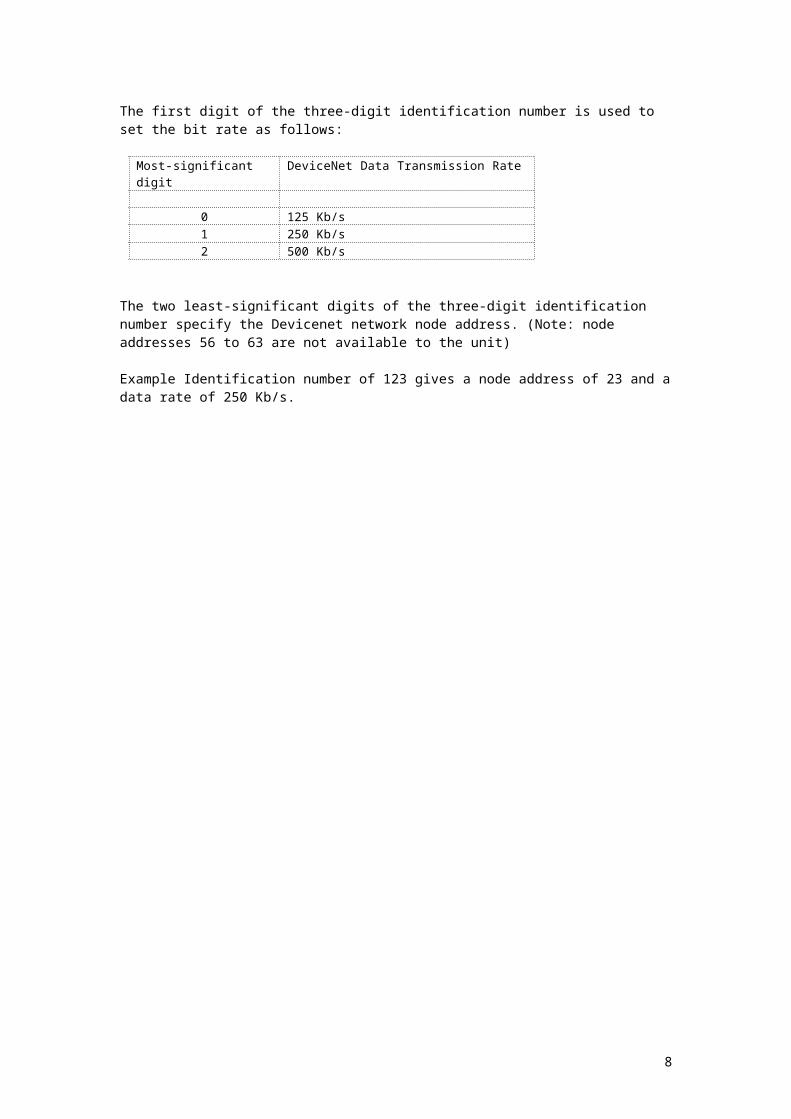
The first digit of the three-digit identification number is used to set the bit rate as follows:
Most-significant digit DeviceNet Data Transmission Rate
0 125 Kb/s1 250 Kb/s2 500 Kb/s
The two least-significant digits of the three-digit identification number specify the Devicenet network node address. (Note: node addresses 56 to 63 are not available to the unit)
Example Identification number of 123 gives a node address of 23 and a data rate of 250 Kb/s.
6

DeviceNet Wiring Connections
On External Maguire Gateways the DeviceNet connections are made directly to the screw terminals on the top side of the Gateway. These are colour coded as follows:
Colour Use
Black V-, 0V.Blue CAN_L.
Shield DRAIN.White CAN_H.
For the internal unit the connections are as per the standard for 5-way connector and are: -
DeviceNet Connections (Internal Card)
Looking into the connector, the five connections are, left to right, as follows:
Use Description Colour
V- 0v return for +24v supply BlackCAN_L Data Low BlueShield Chassis Ground Bare-wireCAN_H Data High WhiteV+ +24v Supply (+11v to +30V) Red
7
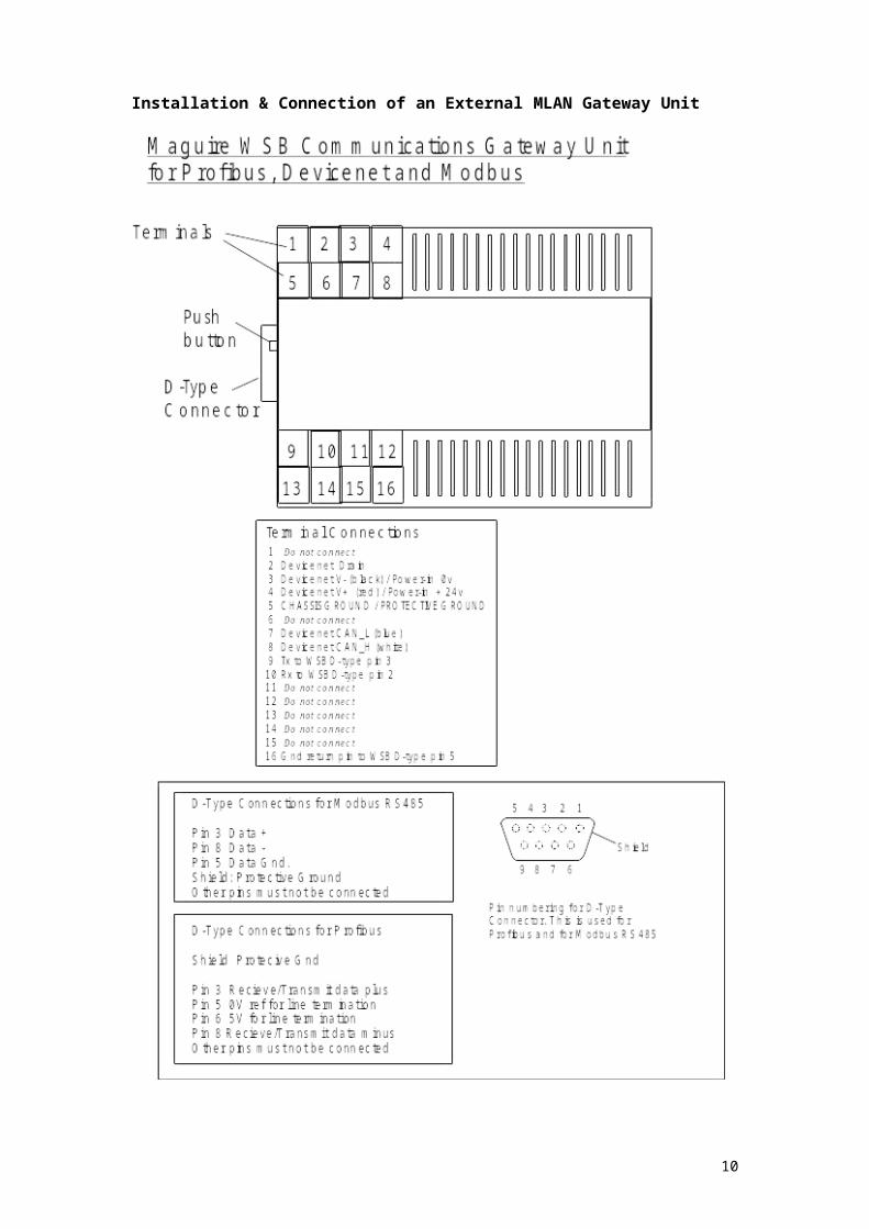
Installation & Connection of an External MLAN Gateway Unit
8

Installation & Connection of an Internal MLAN Gateway Card
To fit an internal MLAN Gateway Card to an existing Maguire blender controller please follow these instructions;
Firstly remove the 4 screws on top of the Controller, 3 from the left hand side, and then 3 screws underneath the controller towards the front side. Once the controller is open then do the following;
Once all of the screws have been removed from the controller open the controller to expose all internal cards and wiring.
The MLAN Gateway replaces the RS232 Computer port situated on the left hand side panel of the controller.
The Computer port is shown from reverse, being the top port on the panel.
To remove the existing computer port unscrew the two connection screws and remove the ribbon connector from the main board.
Using the two connector screws from the computer port you have removed, fit the MLAN Gateway in place of the computer port. Then connect the ribbon cable from the MLAN gateway onto the RS232 position on the main board of the controller.
Once the card has been installed, it is then necessary to provide the MLAN Gateway with a 24V DC feed.
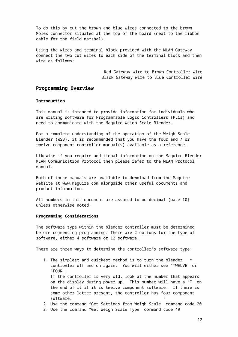
To do this by cut the brown and blue wires connected to the brown Molex connector situated at the top of the board (next to the ribbon cable for the field marshal).
Using the wires and terminal block provided with the MLAN Gateway connect the two cut wires to each side of the terminal block and then wire as follows:
Red Gateway wire to Brown Controller wireBlack Gateway wire to Blue Controller wire
9
Programming Overview
Introduction
This manual is intended to provide information for individuals who are writing software for Programmable Logic Controllers (PLCs) and need to communicate with the Maguire Weigh Scale Blender.
For a complete understanding of the operation of the Weigh Scale Blender (WSB), it is recommended that you have the four and / or twelve component controller manual(s) available as a reference.
Likewise if you require additional information on the Maguire Blender MLAN Communication Protocol then please refer to the MLAN Protocol manual.
Both of these manuals are available to download from the Maguire website at www.maguire.com alongside other useful documents and product information.
All numbers in this document are assumed to be decimal (base 10) unless otherwise noted.
Programming Considerations
The software type within the blender controller must be determined before commencing programming. There are 2 options for the type of software, either 4 software or 12 software.
There are three ways to determine the controller’s software type:
1. The simplest and quickest method is to turn the blender controller off and on again. You will either see “TWELVE” or “FOUR”. If the controller is very old, look at the number that appears on the display during power up. This number will have a “T” on the end of it if it is twelve component software. If there is some other letter present, the controller has four component software.
2. Use the command “Get Settings from Weigh Scale” command code 20 3. Use the command “Get Weigh Scale Type” command code 49
Messages and responses are different according to which type of software is used. For example, the “Send Settings to the Weigh Scale” command (command code 19) has different formats for each software type.
Finally, the blender series must be known. Blender load cells read in either tenths of grams or whole grams. These are as follows:
Load Cells for the Micro blender, 100 and 200 series of blenders read in tenths of grams.
Load Cells for the 400, 900, and 1800 series of blenders read in whole grams.
For example, a response of 234 from a 100 or 200 series blender indicates that 23.4 grams of material have been processed. A response of 234 from a 400, 900, or 1800 series blender indicates that 234 grams of material have been processed.
10

Summary of all MLAN commands
MLAN Command Code Description
Clear Totals 24 Resets all materials totals to zero at the end of the next blender cycle.Clear Totals Immediately
28 Resets all materials totals to zero immediately.
Get Address 54 Returns Controller Address *** Not supported by the MLAN Gateway Adapter ***
Get All Parameters 22 Returns all of the parameters and their values *** Not supported by the MLAN Gateway Adapter ***
Get Batch Info 84 Returns the batch weight, current portion of the batch, accumulated total and batch count number.(See WSB Manual for more information on how the WSB operates)
Get Cycle Weight & Time
50 Returns the size of the last batch / cycle and the duration of time between the last two cycles.
Get Display 56 Returns the current display buffer.Get Parameter 69 Returns the value of a specific parameter.Get Settings 20 Returns the mix percentages and component types along with the recipe, work
order and operator number.Get Status 53 Returns the current state of all signal inputs and outputs.Get Steady State Rate 64 Returns the steady state throughput rate of the blender.Get Target Throughput & Status
29 Returns the current target throughput and the extrusion control status.
Get Totals 16 Returns the current totals and resets the internal flagGet Totals 17 Returns the current totals without resetting the internal flagGet Type 49 Returns the controller software type (4 or 12) and load cell type (tenths of grams
or full grams)Get Version 80 Returns the version of software in the controller.Get Weigh Units 85 Returns the units that the blender is using to display totals – Pounds, Kilograms,
Ounces or GramsSend Keystroke 87 Sends a virtual keystroke to the keypad on the controller – see Set Remote
KeypadSend Settings 19 Sets the mix percentages and material types – also sets work order and operator
numbers.Set Batch Weight 83 Sets the size of a single batch in blender in grams. Set Date & Time 81 Sets the Date and Time of a blender.Set Parameter 68 Sets the value of a specific parameter.Set Remote Keypad 88 Enable / Disable Controller Keypad and or the “Send Keystroke” commandSet Steady Rate 65 Sets the steady state throughput rate of the blender – this tells the blender the
rate to report back for the “Get Steady State Rate” commandSet Tag 90 Sets either recipe, operator or work order number on the controller.Set Target Throughput 30 Sets the target throughput rate for extrusion control mode.Set Weight Units 86 Sets the weight unit used by the blender to display totals such as pounds or kilos.Silence Alarm 82 Silences the alarm for a specific blenderStart / Stop / Status 55 Instructs the blender to stop at the end of the current cycle, start up, or return
current operating status. Stop Cycle / Stop Retry 27 Instructs the blender to abort current cycle or current material dispense.
Aborting current cycle cause blender to start a new cycle.Aborting current dispense causes the blender to start dispensing the next material in its current settings.
11
MLAN Command HistoryThe following table documents when commands have been added to the MLAN software. The chip version number can be found on the MLAN chip within the controller.
In most cases with the introduction of new commands to the software in MLAN chips, 12 software chips were either first to be updated or both the 12 software and the 4 software chips were updated at the same time.
Not all chips are listed below. What are listed are chips that marked a change in the software and were available for testing. If your chip is not listed, it may indicate that your chip did not mark a change in the software or possibly it was not available for testing when this information was compiled.
Chips versions numbers indicate a date. For instance chip "60603A" means 1996 (6), June (06), 3rd (03) followed by "T" or “TC” for twelve software or "A" or “WS” for four software. Your chip version number may fall somewhere in between the chips listed below if it is not directly listed.
Other Notes:
Controllers using chips prior to 60603A (06/03/1996) have an earlier circuit board, which would need replacement if the chip is to be updated.
Chips after 90317A (03/17/1999) will have all parameters available.
Chips prior to 90317A (03/17/1999), please see chart on the following page.
MLAN Command Chip Version Printed on Chip
MLAN Command Chip Version Printed on Chip
Get Version 60603A Get Weight Units 60710TClear Totals 20414A Set Remote Keypad 60911TClear Totals Immediately 80609A Send Keystroke 60911TGet Address 50925A Send Settings 20414TGet All Parameters 60809A Set Batch Weight 60603AGet Batch Info 60603A Set Date & Time 60603AGet Cycle, Weight & Time 30913A Set Parameter 70529AGet Display 50925A Set Steady State Rate 70916TGet Parameter 70205T Set Tag 60710TGet Settings 20414A Set Target Throughput 90317AGet Status 41019A Set Weight Units 60710TGet Steady State Rate 60603A Silence Alarm 60603AGet Target Throughput Status
90317A Start / Stop / Status 60603A
Get Totals 20414A Stop Cycle / Stop Retry 71222TGet Type 20414A XT Parameters 60603A
PLEASE NOTE:
Depending on the date of the chip in your controller, all commands may not be available. The chips can be upgraded, so if you need a newer chip, please contact your nearest Maguire reseller.
12

DeviceNet Communication for WSB
General Information
Within the constraints of DeviceNet, the protocol used has been designed to be as consistent as possible with the MLAN command set.
The DeviceNet Polled Input/Output for a slave node appears as a block of output registers/memory, and a block of input registers/memory.
The registers are generally word (two-byte) values. Values shown are decimal (base 10) values.
Table 1: General Command Format Output on DeviceNet (Polled I/O Data) Output Address (Word offset) Function0 Command Code1 Variable 12 Variable 23 to 32 Variables 3..4..5…
.Table 2: Input Data: Reply to Command Input Address (Byte offset) Function0 Totalized Comms Error count1 Command Confirmation2 Comms Status (current command)3 Variable 14 Variable 25 to 32 Variables 3..4..5…
On an Allen Bradley PLC for example output registers may be referred to as:
O:S.0O:S.1
Where “S” is the slot number within the PLC where the DeviceNet scanner card resides. If this were slot 1, then the first two output words would be
O:1.0 and O:1.1.
Similarly the first two input words would be referred to as
I:1.0 and I:1.1
Commands are initiated by writing the appropriate values to a set of output registers. The precise sequence is described in the following paragraphs. The sequence is important. The reply to each command can be read from the input registers. Once again the operational sequence is important.
The command codes are the same as those used for the MLAN communication. The number denoting each command is shown in table 3.
13

The parameters (variables) associated with the command should be written first (address 1 upwards), followed by the command number (address 0). The writing of the command number causes the WSB DeviceNet interface to execute the command. It is the change in this value that initiates the slave action. Consequently, if two commands of the same type are to be executed consecutively, then a “Null-Command” (zero) should be executed between the two similar commands.
The checksum specified in the MLAN protocol is NOT used in the DeviceNet communication. Error checking is taken care of automatically by the Profibus software.
The DeviceNet Input and Output parameters are arranged in word (two-byte) values as this is more easily accommodated by certain PLCs than byte-orientated information.
When the blender controller has executed the command, the command number is echoed in the “command-confirmation” input word. Note that the command confirmation always echoes the command number so that the PLC can know which command is being acknowledged.
This differs slightly from the MLAN protocol where some commands reply with the “48” reply code. As the data is cyclic, this echo is necessary to confirm which command is being replied to.
Command Structure
In order to send a command to the WSB over DeviceNet, the PLC should apply the following procedure.
1. Write the variables associated with the commands to output register addresses 1 upwards.
2. Write the command number to address 03. Repeatedly read input address 1 until its value matches the command placed in
output location 04. Read Comms Status (current command): input location 25. If Comms Status (step 4) was zero, then the variables of the command reply can be
read from locations 3, 4, 5..
Totalized Error Count
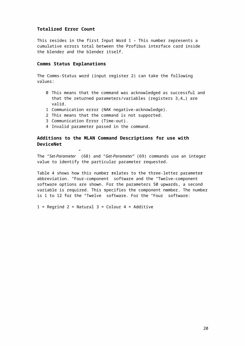
This resides in the first Input Word 1 – This number represents a cumulative errors total between the Profibus interface card inside the blender and the blender itself.
Comms Status Explanations
The Comms-Status word (input register 2) can take the following values:
0 This means that the command was acknowledged as successful and that the returned parameters/variables (registers 3,4…) are valid.
1 Communication error (NAK negative-acknowledge).2 This means that the command is not supported.3 Communication Error (Time-out).4 Invalid parameter passed in the command.
Additions to the MLAN Command Descriptions for use with DeviceNet
The “Set-Parameter” (68) and “Get-Parameter” (69) commands use an integer value to identify the particular parameter requested.
Table 4 shows how this number relates to the three-letter parameter abbreviation. “Four-component” software and the “Twelve-component” software options are shown. For the parameters 50 upwards, a second variable is required. This specifies the component number. The number is 1 to 12 for the “Twelve” software. For the “Four” software:
14

1 = Regrind 2 = Natural 3 = Colour 4 = Additive
15

DeviceNet Slave Parameterisation: User-parameters
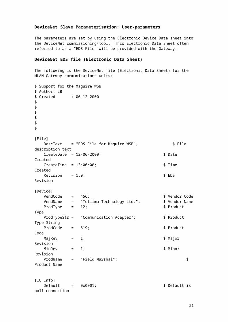
The parameters are set by using the Electronic Device Data sheet into the DeviceNet commissioning tool. This Electronic Data Sheet often referred to as a “EDS File” will be provided with the Gateway.
DeviceNet EDS file (Electronic Data Sheet)
The following is the DeviceNet file (Electronic Data Sheet) for the MLAN Gateway communications units:
$ Support for the Maguire WSB$ Author: LB$ Created : 06-12-2000$$$$$$
[File] DescText = "EDS File for Maguire WSB"; $ File description text CreateDate = 12-06-2000; $ Date Created CreateTime = 13:00:00; $ Time Created Revision = 1.0; $ EDS Revision
[Device] VendCode = 456; $ Vendor Code VendName = "Tellima Technology Ltd."; $ Vendor Name ProdType = 12; $ Product Type ProdTypeStr = "Communication Adapter"; $ Product Type String ProdCode = 819; $ Product Code MajRev = 1; $ Major Revision MinRev = 1; $ Minor Revision ProdName = "Field Marshal"; $ Product Name
[IO_Info] Default = 0x0001; $ Default is poll connection PollInfo = 0x0003, 1, 1; $ Default In is 1 default out is 1
Input1 = 66, $ Produce 66 bytes maximum 8, $ 8 bits valid 0x0001, $ Only Poll "I/O Data", $ Name String 66, $ Path Size
16

"20 04 24 01 30 03", $ Path Descriptor "33 Words of Messaging"; $ Help String Output1 = 66, $ Consume 66 bytes maximum 8, $ 8 bits valid 0x0001, $ Only Poll "I/O Data", $ Name String 66, $ Path Size "20 04 24 01 30 03", $ Path Descriptor "33 Words of Messaging"; $ Help String
DeviceNet Command Example
The example below illustrates the “Get-Parameter _LA (Lag Time) for component 3” command over DeviceNet. The Purpose of this would be to retrieve the setting for the Lag Time (LA parameter) for hopper / component number 3 on a blender:
Example Get Parameter Command _LA component 3 Output Address (word offset) Function Description
0 69 MLAN Command Code Get Parameter1 62 Profibus Reference number for the LA Parameter2 3 Hopper / Component number3 to 32 Unused
Table 2: Input Data: Reply to Command Input Address (Byte offset) Reply Description
0 0 Totalized errors 01 69 Command confirmation 692 0 Comms status (ok) 03 20 (_AL value) 204 Unused5 to 32 Unused
Explanations of returned values:
0 is the totalized errors (not specific to this command)69 confirms that the get parameter command has been executed0 means that the command executed successfully20 is the _AL value returned for component 3
Please refer to Table 4 on the next page to see the DeviceNet reference number for other MLAN parameters.
17

DeviceNet Reference Numbers for Blender Parameters(Reference Table 4)
Profibus Reference #
4 Software Parameters
12 Software Parameters
Profibus Reference #
4 Software Parameters
4 Software Component #
12 Software Parameters
12 Software Component #
1 FLG FLG 50 _TY 1 TO 12 2 MIX MIX 51 _CS 1 TO 12 3 FCV FCV 52 RAL 1 _AL 1 TO 12 4 DTI DTI NAL 2 5 KDF KDF CAL 3 6 WDF WDF AAL 4 7 BER BER 53 CXT 3 _XT 1 TO 12 8 ROC ROC AXT 4 9 ROV ROV 54 RSE 1 _SE 1 TO 12 10 RHL RHL CSE 3 11 FUL FUL ASE 4 12 MAX MAX 55 RWT 1 _WT 1 TO 12 13 TH TH NWT 2 14 TL TL CWT 3 15 PRT PRT AWT 4 16 RLO 56 RTI 1 _TI 1 TO 12 17 DLY DLY NTI 2 18 LT1 CTI 3 19 LT2 ATI 4 20 PRC PRC 57 RMI 1 _MI 1 TO 12 21 STL STL NMI 2 22 LCL LCL CMI 3 23 LCH LCH AMI 4 24 LCF LCF 58 RNC 1 _NC 1 TO 12 25 LCZ LCZ NNC 2 26 DS1 CNC 3 27 DS2 ANC 4 28 SCR SCR 59 RPT 1 _PT 1 TO 12 28 BCR BCR NPT 2 30 XCV XCV CPT 3 31 XRC XRC APT 4 32 TCV TCV 60 RRP 1 _RP 1 TO 12 33 TRC TRC NRP 2 34 XTP XTP CRP 3 35 XAL XAL ARP 4 36 XUL XUL 61 RRD 1 _RD 1 TO 12 37 CPL CPL NRD 2 38 MPO MPO CRD 3 ARD 4 62 RLA 1 _LA 1 TO 12 NLA 2 CLA 3
18

Data Commands
Clear TotalsDescription: Resets the totals to zero.
Command Format
Output Word # Name Size Range DescriptionO:1.0 Command Code 1 24 Clear Totals Command
Response Format
Input Word # Name Size Range Description
I:1.0 Totalized Error Count 1 0 to 65535Cumulative Communication Errors Totals
I:1.1 Command Confirmation 1 24Command Completed; subsequent values now valid
I:1.2Comms Status (Current Command) 1 0 to 4
0 = Command Executed Successfully1 = Command Failed
NOTE: The totals will not be erased until the end of the current cycle. If the blender is idle, the totals will be cleared at the end of the next cycle.
Clear Totals ImmediatelyDescription: Resets the totals to zero.
Command Format
Output Word # NameSize Range Description
O:1.0 Command Code 1 28Clear Totals Immediately Command
Response Format
Input Word # NameSize Range Description
I:1.0 Totalized Error Count 1 0 to 65535Cumulative Communication Errors Totals
I:1.1 Command Confirmation 1 28Command Completed; subsequent values now valid
I:1.2Comms Status (Current Command) 1 0 to 4
0 = Command Executed Successfully1 = Command Failed
NOTE: The totals will be erased immediately.
19
Get All ParametersDescription: Gets all of the parameters and their values.
*** This MLAN command is not supported by Profibus as data size exceeds allowable field ***
Get Batch InfoDescription: Returns the batch weight, current portion, accumulated total, and batch count.
Command Format
Output Word # Name Size Range Description
O:1.0 Command Code 1 84Get Batch Information Command
Response Format
Input Word # Name Size Range Description
I:1.0 Totalized Error Count 1 0 to 65535Cumulative Communication Errors Totals
I:1.1 Command Confirmation 1 84Command Completed; subsequent values now valid
I:1.2Comms Status (Current Command) 1 0 to 4
Must be 0 for subsequent variables to be valid
I:1.3 Batch Weight 1 0 to 65535Batch Weight (Pounds or Kilos only)
I:1.4 Current portion 1 0 to 65535Completed portion of current batch
I:1.5 Accumulative Total 1 0 to 65535Total weight of all completed batches
I:1.6 Batch Count 1 0 to 65535Total number of completed batches
Note 1: Batch weight is given in pounds if "Get Weight Units" returns either pounds or ounces.If "Get Weight Units" returns either kilograms or grams, then batch weight is in kilograms.
20
Get Cycle Weight and TimeDescription: Returns the size of the last batch/cycle and the duration of time between
the last two cycles.
Command Format
Output Word # NameSize Range Description
O:1.0 Command Code 1 50Get Batch Information Command
Response Format
Input Word # NameSize Range Description
I:1.0 Totalized Error Count 1 0 to 65535Cumulative Communication Errors Totals
I:1.1 Command Confirmation 1 50Command Completed; subsequent values now valid
I:1.2Comms Status (Current Command) 1 0 to 4
Must be 0 for subsequent variables to be valid
I:1.3 Cycle Weight 1 0 to 65536Grams (or tenths of grams) in last cycle
I:1.4 –I:1.5Cycle Time 2 0 to 4294967295 Number of interrupts during
the last cycle (244/sec)
Get DisplayDescription: Returns the current light emitting diode (LED) buffer.
Command Format
Output Word # Name Size Range DescriptionO:1.0 Command Code 1 56 Get Display Command
Response Format
Input Word # Name Size Range Description
I:1.0 Totalized Error Count 1 0 to 65535Cumulative Communication Errors Totals
I:1.1 Command Confirmation 1 56Command Completed; subsequent values now valid
I:1.2Comms Status (Current Command) 1 0 to 4
Must be 0 for subsequent variables to be valid
I:1.3 - I:1.10 Display 8 ASCII
ASCII characters currently displayed on LED. 1 Char per Word
IW6 is the leftmost character
21

Get ParameterDescription: Gets a single parameter.
Command Format
Output Word # NameSize Range Description
O:1.0 Command Code 1 69 Get Parameter Command
O:1.1 Parameter reference number 1 0 to 63Parameter number – please refer to table below
O:1.2 Component Number 11 to 41 to 12
1 – 4 = 4 Software (R,N,C,A)1 – 12= 12 Software (1,2,3,4,5,6,7,8,9,10,11,12)
Response Format
Input Word # NameSize Range Description
I:1.0 Totalized Error Count 1 0 to 65535
Cumulative Communication Errors Totals
I:1.1 Command Confirmation 1 69
Command Completed; subsequent values now valid
I:1.2 Comms Status (Current Command) 1 0 to 4Must be 0 for subsequent variables to be valid
I:1.3 Parameter Value 1 0 to 65535The value of the parameter.
NOTE: Parameter definitions are given in the blender manual.
22

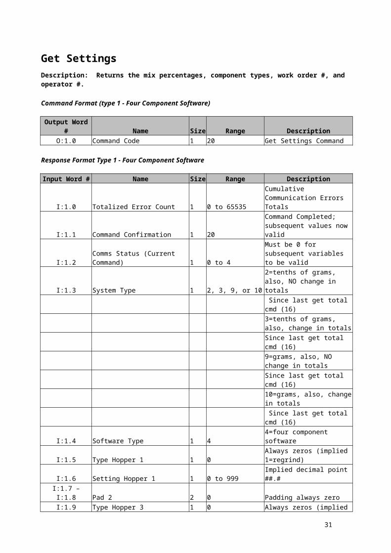
Get SettingsDescription: Returns the mix percentages, component types, work order #, and operator #.
Command Format (type 1 - Four Component Software)
Output Word # Name Size Range DescriptionO:1.0 Command Code 1 20 Get Settings Command
Response Format Type 1 - Four Component Software
Input Word # Name Size Range Description
I:1.0 Totalized Error Count 1 0 to 65535Cumulative Communication Errors Totals
I:1.1 Command Confirmation 1 20Command Completed; subsequent values now valid
I:1.2Comms Status (Current Command) 1 0 to 4
Must be 0 for subsequent variables to be valid
I:1.3 System Type 1 2, 3, 9, or 102=tenths of grams, also, NO change in totals
Since last get total cmd (16)
3=tenths of grams, also, change in totals
Since last get total cmd (16)
9=grams, also, NO change in totals
Since last get total cmd (16)
10=grams, also, change in totals
Since last get total cmd (16)I:1.4 Software Type 1 4 4=four component software
I:1.5 Type Hopper 1 1 0Always zeros (implied 1=regrind)
I:1.6 Setting Hopper 1 1 0 to 999 Implied decimal point ##.# I:1.7 – I:1.8 Pad 2 2 0 Padding always zero
I:1.9 Type Hopper 3 1 0Always zeros (implied 3=color)
I:1.10 Setting Hopper 3 1 0 to 999 Implied decimal point ##.#
I:1.11 Type Hopper 4 1 0Padding always zeros (implied 3=additive)
I:1.12 Setting Hopper 4 1 0 to 999 Implied decimal point ##.# I:1.13 – I:1.28 Pad 5-12 16 0 Padding always zero
I:1.29 Recipe number 1 100 to 65535 Recipe numberI:1.30 Operator number 1 0 to 999 Operator number
I:1.31 – I:1.32 Work Order Number 2 0 to 999999 Work order number
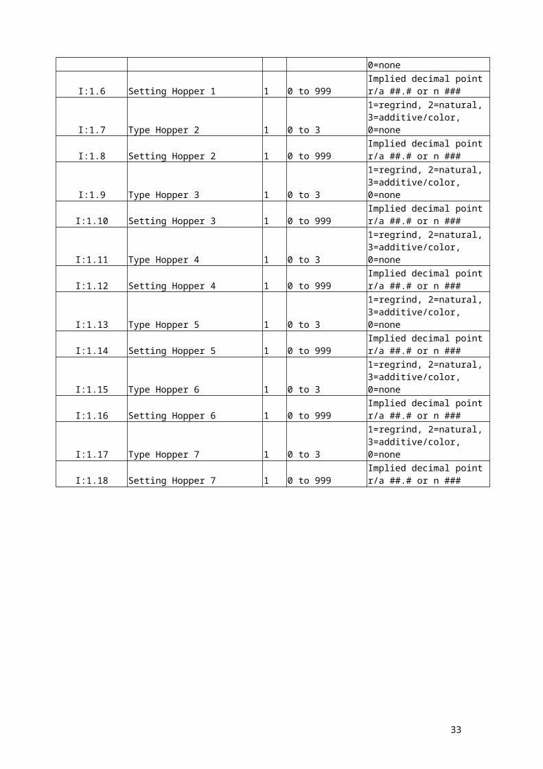
Response Format Type 2 - Twelve Component Software
Input Word # Name Size Range Description
I:1.0 Totalized Error Count 1 0 to 65535Cumulative Communication Errors Totals
I:1.1 Command Confirmation 1 20Command Completed; subsequent values now valid
23

I:1.2Comms Status (Current Command) 1 0 to 4
Must be 0 for subsequent variables to be valid
I:1.3 System Type 1 2, 3, 9, or 102=tenths of grams, also, NO change in totals
Since last get total cmd (16)
3=tenths of grams, also, change in totals
Since last get total cmd (16)
9=grams, also, NO change in totals
Since last get total cmd (16)
10=grams, also, change in totals
Since last get total cmd (16)
I:1.4 Software Type 1 1212=twelve component software
I:1.5 Type Hopper 1 1 0 to 31=regrind, 2=natural, 3=additive/color, 0=none
I:1.6 Setting Hopper 1 1 0 to 999Implied decimal point r/a ##.# or n ###
I:1.7 Type Hopper 2 1 0 to 31=regrind, 2=natural, 3=additive/color, 0=none
I:1.8 Setting Hopper 2 1 0 to 999Implied decimal point r/a ##.# or n ###
I:1.9 Type Hopper 3 1 0 to 31=regrind, 2=natural, 3=additive/color, 0=none
I:1.10 Setting Hopper 3 1 0 to 999Implied decimal point r/a ##.# or n ###
I:1.11 Type Hopper 4 1 0 to 31=regrind, 2=natural, 3=additive/color, 0=none
I:1.12 Setting Hopper 4 1 0 to 999Implied decimal point r/a ##.# or n ###
I:1.13 Type Hopper 5 1 0 to 31=regrind, 2=natural, 3=additive/color, 0=none
I:1.14 Setting Hopper 5 1 0 to 999Implied decimal point r/a ##.# or n ###
I:1.15 Type Hopper 6 1 0 to 31=regrind, 2=natural, 3=additive/color, 0=none
I:1.16 Setting Hopper 6 1 0 to 999Implied decimal point r/a ##.# or n ###
I:1.17 Type Hopper 7 1 0 to 31=regrind, 2=natural, 3=additive/color, 0=none
I:1.18 Setting Hopper 7 1 0 to 999Implied decimal point r/a ##.# or n ###
24

Response Format Type 2 - Twelve Component Software - continued
I:1.19 Type Hopper 8 1 0 to 31=regrind, 2=natural, 3=additive/color, 0=none
I:1.20 Setting Hopper 8 1 0 to 999Implied decimal point r/a ##.# or n ###
I:1.21 Type Hopper 9 1 0 to 31=regrind, 2=natural, 3=additive/color, 0=none
I:1.22 Setting Hopper 9 1 0 to 999Implied decimal point r/a ##.# or n ###
I:1.23 Type Hopper 10 1 0 to 31=regrind, 2=natural, 3=additive/color, 0=none
I:1.24 Setting Hopper 10 1 0 to 999Implied decimal point r/a ##.# or n ###
I:1.25 Type Hopper 11 1 0 to 31=regrind, 2=natural, 3=additive/color, 0=none
I:1.26 Setting Hopper 11 1 0 to 999Implied decimal point r/a ##.# or n ###
I:1.27 Type Hopper 12 1 0 to 31=regrind, 2=natural, 3=additive/color, 0=none
I:1.28 Setting Hopper 12 1 0 to 999Implied decimal point r/a ##.# or n ###
I:1.29 Recipe number 1 100 to 65536 Recipe numberI:1.30 Operator number 1 0 to 999 Operator number
I:1.31 – I:1.32 Work Order Number 2 0 to 999999 Work order number
25

Get StatusDescription: Returns the current state of all signal inputs and outputs.
Command Format
Output Word # Name Size Range DescriptionO:1.0 Command Code 1 53 Get Status Command
Response Format
Input Word # Name Size Range Description
I:1.0 Totalized Error Count 1 0 to 65535Cumulative Communication Errors Totals
I:1.1 Command Confirmation 1 20Command Completed; subsequent values now valid
I:1.2Comms Status (Current Command) 1 0 to 4
Must be 0 for subsequent variables to be valid
I:1.3 Output Status 1 0 to 65535 See note 1I:1.4 Alarm Status 1 0 to 255 See note 2I:1.5 Sensor Status 1 0 to 255 See note 3
Note 1a - Output status for FOUR component software
BIT Name Value Description0 Mixer Valve 1=open 0=closed Rightmost bit1 Reserved 1=open 0=closed 2 Reserved 1=open 0=closed 3 Reserved 1=open 0=closed 4 Reserved 1=open 0=closed 5 Reserved 1=open 0=closed 6 Reserved 1=open 0=closed 7 Reserved 1=open 0=closed 8 Mix Motor 1=open 0=closed 9 Alarm 1=open 0=closed
10 Weigh Bin Valve 1=open 0=closed 11 Additive 1=open 0=closed 12 Color 1=open 0=closed 13 Natural 1=on 0=off 14 Regrind 1=open 0=closed 15 Reserved 1=on 0=off Leftmost bit
26

Note 1b - Output status for TWELVE component software
BIT Name Value Description0 Component 1 1=open 0=closed Rightmost bit1 Component 2 1=open 0=closed 2 Component 3 1=open 0=closed 3 Component 4 1=open 0=closed 4 Component 5 1=open 0=closed 5 Component 6 1=open 0=closed 6 Component 7 1=open 0=closed 7 Component 8 1=open 0=closed 8 Component 9 1=open 0=closed 9 Component 10 1=open 0=closed
10 Component 11 1=open 0=closed 11 Component 12 1=open 0=closed 12 Weigh Bin Valve 1=open 0=closed 13 Mix Motor 1=on 0=off 14 Mixer Valve 1=open 0=closed 15 Alarm 1=on 0=off Leftmost bit
Note 2 - Alarm Status
BIT Name Value Description
0 to 6 Alarm Code1 to 12=Component alarm
Bit 0 is the rightmost bit
13 = Batch Alarm 14 = Bail Out Alarm 15 = Dump Alarm 7 Alarm Silenced 1 = silenced Leftmost bit
8-15 Unused
Note 3 - Sensor Status
BIT Name Value Description0 Empty bin mix motor 1=yes 0=no Rightmost bit
sensor or switch 1 to 3 Reserved
4 Manual Mode 1=yes 0=no 5 Program Mode 1=yes 0=no 6 Running Mode 1=yes 0=no 7 Soft Stop Mode * 1=yes 0=no Leftmost bit
* See Start/Stop/Status command
8-15 Unused
27

Get Steady State RateDescription: Returns throughput rate.
Command Format
Output Word # Name Size Range Description
O:1.0 Command Code 1 64Get Steady State Rate Command
Response Format
Input Word # Name Size Range Description
I:1.0 Totalized Error Count 1 0 to 65535Cumulative Communication Errors Totals
I:1.1 Command Confirmation 1 64Command Completed; subsequent values now valid
I:1.2Comms Status (Current Command) 1 0 to 4
Must be 0 for subsequent variables to be valid
I:1.3 – I:1.4 Steady State Rate 2 0 to 4294967295Grams (or tenths of grams) per hour
28

Get Target Throughput & StatusDescription: Returns the target throughput rate for extrusion control.
See XCV parameter in blender manual for more information.
Command Format
Output Word # Name Size Range Description
O:1.0 Command Code 1 29Get Target Throughput & Status Command
Response Format
Input Word # Name Size Range Description
I:1.0 Totalized Error Count 1 0 to 65535Cumulative Communication Errors Totals
I:1.1 Command Confirmation 1 29Command Completed; subsequent values now valid
I:1.2Comms Status (Current Command) 1 0 to 4
Must be 0 for subsequent variables to be valid
I:1.3 Status 1 0 to 255 See note 1
I:1.4 Steady State Rate 20 to 4294967295
Grams (or tenths of grams) per hour
Note 1 – Status
BIT Name Value Description
0 Extrusion control1=on 0=off Bit 0 is the rightmost bit
1 1=steady 0=not steady T or no T on display
2 1=Throughput 0=Voltage Controlling mode
3 1=Grams 0=Tenths of Grams Weight unit of rate
4 1=Yield 0=Weight See note 25 - 15 Reserved Leftmost bit
Note 2: If the extrusion process is being controlled by weight, then the output will be a steadyweight per time (e.g. lbs/hr). If however the extrusion process is being controlled by yield, then the output will be a steady weight per length (e.g. lbs/foot).
29

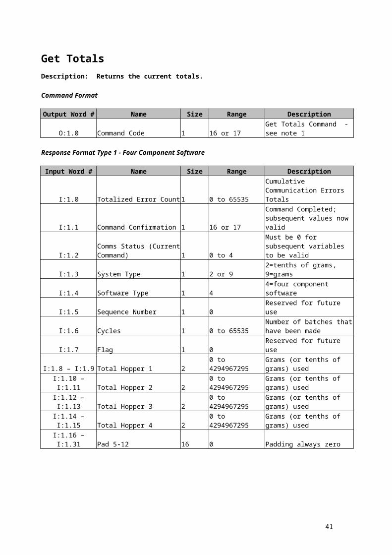
Get TotalsDescription: Returns the current totals.
Command Format
Output Word # Name Size Range Description
O:1.0 Command Code 1 16 or 17Get Totals Command - see note 1
Response Format Type 1 - Four Component Software
Input Word # Name Size Range Description
I:1.0 Totalized Error Count 1 0 to 65535Cumulative Communication Errors Totals
I:1.1 Command Confirmation 1 16 or 17Command Completed; subsequent values now valid
I:1.2Comms Status (Current Command) 1 0 to 4
Must be 0 for subsequent variables to be valid
I:1.3 System Type 1 2 or 9 2=tenths of grams, 9=gramsI:1.4 Software Type 1 4 4=four component softwareI:1.5 Sequence Number 1 0 Reserved for future use
I:1.6 Cycles 1 0 to 65535Number of batches that have been made
I:1.7 Flag 1 0 Reserved for future use
I:1.8 – I:1.9 Total Hopper 1 2 0 to 4294967295Grams (or tenths of grams) used
I:1.10 – I:1.11 Total Hopper 2 20 to 4294967295 Grams (or tenths of grams)
used
I:1.12 – I:1.13 Total Hopper 3 20 to 4294967295 Grams (or tenths of grams)
used
I:1.14 – I:1.15 Total Hopper 4 20 to 4294967295 Grams (or tenths of grams)
usedI:1.16 – I:1.31 Pad 5-12 16 0 Padding always zero
30
Response Format Type 2 - Twelve Component Software - continued
Input Word # Name Size Range Description
I:1.0 Totalized Error Count 1 0 to 65535Cumulative Communication Errors Totals
I:1.1 Command Confirmation 1 16 or 17Command Completed; subsequent values now valid
I:1.2Comms Status (Current Command) 1 0 to 4
Must be 0 for subsequent variables to be valid1 = No totals available
I:1.3 System Type 1 2 or 9 2=tenths of grams, 9=gramsI:1.4 Software Type 1 4 4=four component softwareI:1.5 Sequence Number 1 0 Reserved for future use
I:1.6 Cycles 1 0 to 65535Number of batches that have been made
I:1.7 Flag 1 0 Reserved for future use
I:1.8 – I:1.9 Total Hopper 1 2 0 to 4294967295Grams (or tenths of grams) used
I:1.10 – I:1.11 Total Hopper 2 20 to 4294967295 Grams (or tenths of grams)
used
I:1.12 – I:1.13 Total Hopper 3 20 to 4294967295 Grams (or tenths of grams)
used
I:1.14 – I:1.15 Total Hopper 4 20 to 4294967295 Grams (or tenths of grams)
used
I:1.16 – I:.17 Total Hopper 5 20 to 4294967295 Grams (or tenths of grams)
used
I:1.18 – I:1.19 Total Hopper 6 20 to 4294967295 Grams (or tenths of grams)
used
I:1.20 – I:1.21 Total Hopper 7 20 to 4294967295 Grams (or tenths of grams)
used
I:1.22 – I:1.23 Total Hopper 8 20 to 4294967295 Grams (or tenths of grams)
used
I:1.24 – I:1.25 Total Hopper 9 20 to 4294967295 Grams (or tenths of grams)
used
I:1.26 – I:1.27 Total Hopper 10 20 to 4294967295 Grams (or tenths of grams)
used
I:1.28 – I:1.29 Total Hopper 11 20 to 4294967295 Grams (or tenths of grams)
used
I:1.30 – I:1.31 Total Hopper 12 20 to 4294967295 Grams (or tenths of grams)
used
Note 1: If the "Command Code" is set to 16, the controller will reset an internal flag indicatingthat the totals have been received. If, however, "Command Code" is set to 17, the flagwill NOT be reset. See the "System Type" part of the "Get Settings" command for howthe internal flag is used.
31

Get TypeDescription: Returns the software type (4 or 12) and load cell type (2 or 9),
(tenths of grams or whole grams)
Command Format
Output Word # Name Size Range DescriptionO:1.0 Command Code 1 49 Get Type Command
Response Format
Input Word # Name Size Range Description
I:1.0 Totalized Error Count 1 0 to 65535Cumulative Communication Errors Totals
I:1.1 Command Confirmation 1 49Command Completed; subsequent values now valid
I:1.2Comms Status (Current Command) 1 0 to 4
Must be 0 for subsequent variables to be valid
I:1.3 System Type 1 2 or 9 2=tenths of grams, 9=gramsI:1.4 Software Type 1 4 or 12 4=four component software
12=twelve component software
Get VersionDescription: Returns the version of the software in the controller.
Command Format
Output Word # NameSize Range Description
O:1.0 Command Code 1 80 Get Version Command
Response Format
Input Word # NameSize Range Description
I:1.0 Totalized Error Count 1 0 to 65535Cumulative Communication Errors Totals
I:1.1 Command Confirmation 1 80Command Completed; subsequent values now valid
I:1.2Comms Status (Current Command) 1 0 to 4
Must be 0 for subsequent variables to be valid
I:1.3 – I:1.8 Version Number 6 ASCIISoftware version number (ASCII)
32
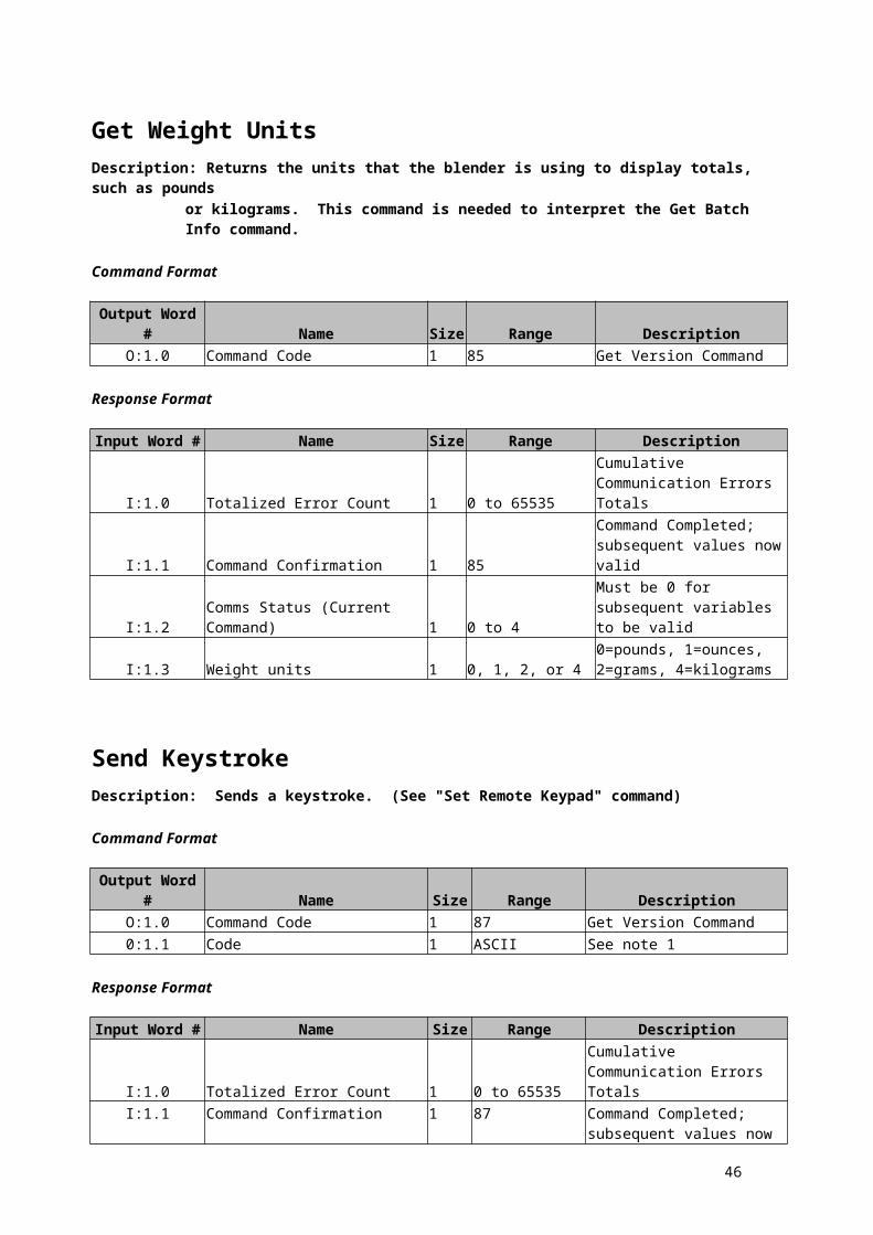
Get Weight UnitsDescription: Returns the units that the blender is using to display totals, such as pounds
or kilograms. This command is needed to interpret the Get Batch Info command.
Command Format
Output Word # Name Size Range DescriptionO:1.0 Command Code 1 85 Get Version Command
Response Format
Input Word # Name Size Range Description
I:1.0 Totalized Error Count 1 0 to 65535Cumulative Communication Errors Totals
I:1.1 Command Confirmation 1 85Command Completed; subsequent values now valid
I:1.2Comms Status (Current Command) 1 0 to 4
Must be 0 for subsequent variables to be valid
I:1.3 Weight units 1 0, 1, 2, or 40=pounds, 1=ounces, 2=grams, 4=kilograms
Send KeystrokeDescription: Sends a keystroke. (See "Set Remote Keypad" command)
Command Format
Output Word # Name Size Range DescriptionO:1.0 Command Code 1 87 Get Version Command0:1.1 Code 1 ASCII See note 1
Response Format
Input Word # Name Size Range Description
I:1.0 Totalized Error Count 1 0 to 65535Cumulative Communication Errors Totals
I:1.1 Command Confirmation 1 87Command Completed; subsequent values now valid
I:1.2Comms Status (Current Command) 1 0 to 4
0 = ack1 = nak
Please refer to notes on the next page:
33

Notes reference Send Keystroke Command:
KEY CODE KEY CODEVIEW Q * *RECP h 0 0BTCH H CE XFAST I HOLD MEXIT E DUMP D ---------------------- -------------------SET S PARA KOPER O ZERO ZTIME T FULL FCAL L MIX G ---------------------- ALRM kTAG eREG R ----------------------1 12 23 3NAT / A A ----------------------4 45 56 6COL / B B ----------------------7 78 89 9ADD / C C ----------------------
34

Send SettingsDescription: Sets the mix percentages, component types, work order #, and operator #.
Command Format Type 1 - Four Component Software
Output Word # Name Size Range DescriptionO:1.0 Command Code 1 19 Send Settings CommandO:1.1 Type Hopper 1 1 1 Always 1=regrindO:1.2 Setting Hopper 1 1 0 to 999 Implied decimal point ##.# O:1.3 Type Hopper 2 1 2 Always 2=naturalO:1.4 Setting Hopper 2 1 0 Always onO:1.5 Type Hopper 3 1 3 Always 3=colorO:1.6 Setting Hopper 3 1 0 to 255 Implied decimal point ##.# O:1.7 Type Hopper 4 1 3 Always 3=additiveO:1.8 Setting Hopper 4 1 0 to 999 Implied decimal point ##.#
O:1.9 – O:1.24 Padding 16 0 Padding always zeroO:1.25 Recipe number 1 100 to 65536 Recipe number
O:1.26 – O:1.27 Work Order Number 2 0 to 999999 Work order numberO:1.28 Operator number 1 0 to 999 Operator number
Command Format Type 2 - Twelve Component Software
Output Word # Name Size Range DescriptionO:1.0 Command Code 1 19 Send Settings Command
O:1.1 Type Hopper 1 1 0 to 31=regrind, 2=natural, 3=additive/color, 0=none
O:1.2 Setting Hopper 1 1 0 to 999Implied decimal point r/a ##.# or n ###
O:1.3 Type Hopper 2 1 0 to 31=regrind, 2=natural, 3=additive/color, 0=none
O:1.4 Setting Hopper 2 1 0 to 999Implied decimal point r/a ##.# or n ###
O:1.5 Type Hopper 3 1 0 to 31=regrind, 2=natural, 3=additive/color, 0=none
O:1.6 Setting Hopper 3 1 0 to 999Implied decimal point r/a ##.# or n ###
O:1.7 Type Hopper 4 1 0 to 31=regrind, 2=natural, 3=additive/color, 0=none
O:1.8 Setting Hopper 4 1 0 to 999Implied decimal point r/a ##.# or n ###
O:1.9 Type Hopper 5 1 0 to 31=regrind, 2=natural, 3=additive/color, 0=none
O:1.10 Setting Hopper 5 1 0 to 999Implied decimal point r/a ##.# or n ###
35

Command Format Type 2 - Twelve Component Software – continued
O:1.11 Type Hopper 6 1 0 to 31=regrind, 2=natural, 3=additive/color, 0=none
O:1.12 Setting Hopper 6 1 0 to 999Implied decimal point r/a ##.# or n ###
O:1.13 Type Hopper 7 1 0 to 31=regrind, 2=natural, 3=additive/color, 0=none
O:1.14 Setting Hopper 7 1 0 to 999Implied decimal point r/a ##.# or n ###
O:1.15 Type Hopper 8 1 0 to 31=regrind, 2=natural, 3=additive/color, 0=none
O:1.16 Setting Hopper 8 1 0 to 999Implied decimal point r/a ##.# or n ###
O:1.17 Type Hopper 9 1 0 to 31=regrind, 2=natural, 3=additive/color, 0=none
O:1.18 Setting Hopper 9 1 0 to 999Implied decimal point r/a ##.# or n ###
O:1.19 Type Hopper 10 1 0 to 31=regrind, 2=natural, 3=additive/color, 0=none
O:1.20 Setting Hopper 10 1 0 to 999Implied decimal point r/a ##.# or n ###
O:1.21 Type Hopper 11 1 0 to 31=regrind, 2=natural, 3=additive/color, 0=none
O:1.22 Setting Hopper 11 1 0 to 999Implied decimal point r/a ##.# or n ###
O:1.23 Type Hopper 12 1 0 to 31=regrind, 2=natural, 3=additive/color, 0=none
O:1.24 Setting Hopper 12 1 0 to 999Implied decimal point r/a ##.# or n ###
O:1.25 Recipe number 1 100 to 999 Recipe numberO:1.26 – O:1.27 Work Order Number 2 0 to 999999 Work order number
O:1.28 Operator number 1 0 to 999 Operator number
Response Format
Input Word # Name Size Range Description
I:1.0 Totalized Error Count 1 0 to 65535Cumulative Communication Errors Totals
I:1.1 Command Confirmation 1 19Command Completed; subsequent values now valid
I:1.2Comms Status (Current Command) 1 0 to 4
0 = ack1 = nak4 = invalid parameter
36

Set Batch WeightDescription: Sets the batch flag parameter and the batch weight.
Command Format
Output Word # Name Size Range DescriptionO:1.0 Command Code 1 83 Set Batch Weight Command
O:1.1 Batch Weight 1 0 to 65536Batch weight (pounds or kilograms only)
(See "Get Weight Units" command for units)
See note 2
O:1.2 Flag 1 0,1, or 20=no batch, 1=alarm & stop, 2=alarm & cont.
See note 1
Response Format
Input Word # Name Size Range Description
I:1.0 Totalized Error Count 1 0 to 65535Cumulative Communication Errors Totals
I:1.1 Command Confirmation 1 19Command Completed; subsequent values now valid
I:1.2Comms Status (Current Command) 1 0 to 4
0 = ack1 = nak4 = invalid parameter
NOTE 1: A flag of 0 means to stop running batches. A flag of 1 means to sound the alarm and stop running at the end of the batch. A flag of 2 means to sound the alarm but continue running at the end of the batch.
NOTE 2: Batch weight is given in pounds if "Get Weight Units" returns either pounds or ounzes.If "Get Weight Units" returns either kilograms or grams, then batch weight is in kilograms.
37

Set Date And TimeDescription: Sets the date and time for a particular blender. If the address is 0, all WSBs
are set with the new date and time and NO response is sent back.
Command Format
Output Word # NameSize Range Description
O:1.0 Command Code 1 81 Set Date and Time Command
O:1.1 – O:1.4 Date and TIme 4See note 1 See note 1
Note 1 - Date and Time
Bit # Name Range Description0 to 7 Padding 0 8 to 11 Seconds (ones place) 0 to 9 yy/mm/dd hh:mm:sS12 to 14 Seconds (tens place) 0 to 5 yy/mm/dd hh:mm:Ss15 Padding 0 16 to 19 Minutes (ones place) 0 to 9 yy/mm/dd hh:mM:ss20 to 22 Minutes (tens place) 0 to 5 yy/mm/dd hh:Mm:ss23 Padding 0 24 to 27 Hours (ones place) 0 to 9 yy/mm/dd hH:mm:ss28 to 29 Hours (tens place) 0 to 2 yy/mm/dd Hh:mm:ss30 Padding 0 31 One 1
32 to 34 Day of week 1 to 7 1 = sunday, 2=monday, ..., 7=saturday
35 Padding 0 36 One 1 37 Padding 0 38 to 39 Padding 0 40 to 43 Day (ones place) 0 to 9 yy/mm/dD hh:mm:ss44 to 45 Day (tens place) 0 to 3 yy/mm/Dd hh:mm:ss46 to 47 Padding 0 48 to 51 Month (ones place) 0 to 9 yy/mM/dd hh:mm:ss52 Month (tens place) 0 or 1 yy/Mm/dd hh:mm:ss53 to 55 Padding 0 56 to 59 Year (ones place) 0 to 9 yY/mm/dd hh:mm:ss60 to 63 Years (tens place) 0 to 9 Yy/mm/dd hh:mm:ss
Response Format
Input Word # Name Size Range DescriptionI:1.0 Totalized Error Count 1 0 to 65535 Cumulative Communication Errors Totals
I:1.1 Command Confirmation 1 81Command Completed; subsequent values now valid
I:1.2Comms Status (Current Command) 1 0 to 4 0 = ack 1 = nak 4 = invalid parameter
38

Set ParameterDescription: Sets a single parameter.
Command Format
Output Word # Name Size Range DescriptionO:1.0 Command Code 1 68 Set Parameter Command
O:1.1Parameter reference number 1 0 to 63
Parameter number – please refer to table below
O:1.2 Component Number 11 to 41 to 12
1 – 4 = 4 Software (R,N,C,A)1 – 12= 12 Software (1,2,3,4,5,6,7,8,9,10,11,12)
O:1.3 Parameter Value 1 0 TO 65535 Value of the Parameter
Response FormatInput Word # Name Size Range Description
I:1.0 Totalized Error Count 1 0 to 65535Cumulative Communication Errors Totals
I:1.1 Command Confirmation 1 68Command Completed; subsequent values now valid
I:1.2Comms Status (Current Command) 1 0 to 4
0 = ack1 = nak4 = invalid parameter
NOTE: Parameters explanations are given in the blender manual.
Set Remote KeypadDescription: Enables or disables the controller's keypad and/or the "Send Keystroke"
MLAN command.
Command Format
Output Word # NameSize Range Description
O:1.0 Command Code 1 88 Set Remote Keypad Command O:1.1 FLAG 1 0 or 1 See note 1
Response Format
Input Word # Name Size Range DescriptionI:1.0 Totalized Error Count 1 0 to 65535 Cumulative Communication Errors Totals
I:1.1 Command Confirmation 1 88Command Completed; subsequent values now valid
I:1.2Comms Status (Current Command) 1 0 to 4
0 = ack1 = nak4 = invalid parameter
Note 1: A flag of 0 enables the keypad on the controller and disables the "Send Keystroke" MLAN command. A flag of 1 disables the keypad and enables the command.
39

Set Steady State RateDescription: Sets throughput rate. Note however that the blender will continue to reset
the rate accordingly to how much material is being consumed. This is useful ifyou know that the rate just changed, such as in extrusion control, and you don'twant to wait until the blender figures it out.
Command Format
Output Word # Name Size Range Description
O:1.0 Command Code 1 65Set Steady State Rate Command
O:1.1 – O:1.2 Steady State Rate 2 0 to 4294967295Grams (or tenths of grams) per hour
Response Format
Input Word # Name Size Range Description
I:1.0 Totalized Error Count 1 0 to 65535Cumulative Communication Errors Totals
I:1.1 Command Confirmation 1 65Command Completed; subsequent values now valid
I:1.2Comms Status (Current Command) 1 0 to 4
0 = ack1 = nak4 = invalid parameter
40
Set TagDescription: Sets a tag value, recipe, work order, and operator #.
Command Format
Output Word # Name Size Range DescriptionO:1.0 Command Code 1 90 Set Tag Command
O:1.1 – O:1.2 Tag ID 2 ASCIITwo letter acronym designating tag.
"RC" = Recipe (1 char per word)
"WO" = Work Order (1 char per word)
"OP" = Operator (1 char per word)
O:1.3 Tag Value 2 0 to 4294967295 The value of the tag.
Recipe numbers: 0 to 65,536.
Work order numbers: 0 to 999,999.
Operator numbers: 0 to 999.
Response Format
Input Word # Name Size Range Description
I:1.0 Totalized Error Count 1 0 to 65535Cumulative Communication Errors Totals
I:1.1 Command Confirmation 1 90Command Completed; subsequent values now valid
I:1.2Comms Status (Current Command) 1 0 to 4
0 = ack1 = nak4 = invalid parameter
41

Set Target ThroughputDescription: Sets the Target Throughput for extrusion control.
See XCV parameter in blender manual for more information.
Command Format
Output Word # Name Size Range Description
O:1.0 Command Code 1 30Set Target Throughput Command
0:1.1 – O:1.2 Target Throughput 2 0 to 4294967295
Response Format
Input Word # Name Size Range Description
I:1.0 Totalized Error Count 1 0 to 65535Cumulative Communication Errors Totals
I:1.1 Command Confirmation 1 30Command Completed; subsequent values now valid
I:1.2Comms Status (Current Command) 1 0 to 4
0 = ack1 = nak4 = invalid parameter
Set Weight UnitsDescription: Sets the units that the blender uses to display totals, such as pounds
or kilograms.
Command Format
Output Word # NameSize Range Description
O:1.0 Command Code 1 86 Set Weight Units Command
O:1.1 Weight units 10, 1, 2, or 4
0=pounds, 1=ounces, 2=grams, 4=kilograms
Response Format
Input Word # NameSize Range Description
I:1.0 Totalized Error Count 1 0 to 65535Cumulative Communication Errors Totals
I:1.1 Command Confirmation 1 86Command Completed; subsequent values now valid
I:1.2Comms Status (Current Command) 1 0 to 4
0 = ack1 = nak4 = invalid parameter
42

Silence AlarmDescription: Has the same effect as if the silence alarm button was pressed.
Command Format
Output Word # Name Size Range DescriptionO:1.0 Command Code 1 82 Silence Alarm Command
Response Format
Input Word # Name Size Range Description
I:1.0 Totalized Error Count 1 0 to 65535Cumulative Communication Errors Totals
I:1.1 Command Confirmation 1 82
Command Completed; subsequent values now valid
I:1.2Comms Status (Current Command) 1 0 to 4
0 = ack1 = nak4 = invalid parameter
43

Start/Stop/StatusDescription: Either causes the WSB to stop at the end of the current cycle, start up again,
or return its current status.
Command Format
Output Word # NameSize Range Description
O:1.0 Command Code 1 55 Start / Stop / Status Command
O:1.1 Subcommand 1 0, 1, or 20=mode status, 1=soft stop, 2=soft start
Response Format (Subcommand 1:stop or 2:start)
Input Word # NameSize Range Description
I:1.0 Totalized Error Count 1 0 to 65535Cumulative Communication Errors Totals
I:1.1 Command Confirmation 1 55Command Completed; subsequent values now valid
I:1.2Comms Status (Current Command) 1 0 to 4
0 = ack1 = nak4 = invalid parameter
Response Format (Subcommand 0:mode status)
Input Word # NameSize Range Description
I:1.0 Totalized Error Count 1 0 to 65535Cumulative Communication Errors Totals
I:1.1 Command Confirmation 1 55Command Completed; subsequent values now valid
I:1.2Comms Status (Current Command) 1 0 to 4
0 = ack1 = nak4 = invalid parameter
I:1.3 Mode 1 0,1,or 2
0 = Hard Stop1= Soft stop2 = Automatic Mode / Running Mode
44

Stop Cycle / Stop RetryDescription: Either causes the WSB to abort the current cycle or the current dispense.
Aborting the current cycle causes the WSB to start the next cycle.Aborting the current dispense causes the WSB to start dispensing thenext component.
Command Format
Output Word # Name Size Range Description
O:1.0 Command Code 1 27Stop Cycle / Stop / Retry Command
O:1.1 Subcommand 1 1 or 21 = Stop Cycle; 2 = Stop Retry
Response Format
Input Word # Name Size Range Description
I:1.0 Totalized Error Count 1 0 to 65535Cumulative Communication Errors Totals
I:1.1 Command Confirmation 1 27
Command Completed; subsequent values now valid
I:1.2Comms Status (Current Command) 1 0 to 4
0 = ack1 = nak4 = invalid parameter
45
Parameter Table from Four Software Blender Software Sample of Software Table
Name Value Name ValueFLG 0 NWT 20800RAL 0 NTI 7808NAL 4 CWT 1024CAL 4 CTI 31232AAL 4 AWT 1024MIX 3010 ATI 31232FCV 5 RMI 325DTI 10 NMI 325KDF 2 CMI 4WDF 2 AMI 1BER 200 RNC 1CXT 0 NNC 1AXT 0 CNC 1ROC 0 ANC 1ROV 0 RRP 10RHL 0 NRP 10FUL 4000 CRP 10MAX 6000 ARP 10TH 200 RRD 81TL 100 NRD 81
PRT 0 CRD 2RSE 1000 ARD 5CSE 1000 RLA 20ASE 1000 NLA 20RLO 50 CLA 15DLY 488 ALA 15LT1 0 PRC 10LT2 0 STL 244RPT 0 LCL 80NPT 0 LCH 120CPT 0 LCF 79APT 0 LCZ 583RWT 20800 XTP 20010RTI 7808
46

Parameter Table for 12 Component Blender Software (Sample as of version 01003T)Prior chip versions may not contain all listed parameters, future chip versions may contain additional parameters.
Name Value Name Value Name Value Name ValueFLG 00000 2TY 00002 5PT 00000 9SE 01000MIX 03010 2CS 00000 5RP 00010 9WT 26000FCV 00006 2AL 00004 5RD 00500 9TI 00976DTI 00006 2XT 00000 5LA 00020 9MI 00001KDF 00010 2SE 01000 5PO 00000 9NC 00010WDF 00010 2WT 26000 6TY 00002 9PT 00000BER 01000 2TI 00976 6CS 00000 9RP 00010ROC 00000 2MI 00001 6AL 00004 9RD 00500ROV 00000 2NC 00010 6XT 00000 9LA 00020RHL 00000 2PT 00000 6SE 01000 9PO 00000FUL 20000 2RP 00010 6WT 26000 ATY 00002MAX 30000 2RD 00500 6TI 00976 ACS 00000 TH 01000 2LA 00020 6MI 00001 AAL 00004 TL 00500 2PO 00000 6NC 00010 AXT 00000PRT 00000 3TY 00002 6PT 00000 ASE 01000DLY 00488 3CS 00000 6RP 00010 AWT 26000PRC 00010 3AL 00004 6RD 00500 ATI 00976STL 00122 3XT 00000 6LA 00020 AMI 00001LCL 00027 3SE 01000 6PO 00000 ANC 00010LCH 00039 3WT 26000 7TY 00002 APT 00000LCF 00079 3TI 00976 7CS 00000 ARP 00010LCZ 00583 3MI 00001 7AL 00004 ARD 00500DS1 00000 3NC 00010 7XT 00000 ALA 00020DS2 00000 3PT 00000 7SE 01000 APO 00000XCV 00000 3RP 00010 7WT 26000 BTY 00002XRC 00001 3RD 00500 7TI 00976 BCS 00000TCV 00000 3LA 00020 7MI 00001 BAL 00004TRC 00004 3PO 00000 7NC 00010 BXT 00000XTP 05050 4TY 00002 7PT 00000 BSE 01000MPO 00183 4CS 00000 7RP 00010 BWT 26000SCR 00000 4AL 00004 7RD 00500 BTI 00976XAL 00005 4XT 00000 7LA 00020 BMI 00001XUL 00200 4SE 01000 7PO 00000 BNC 00010BCR 00000 4WT 26000 8TY 00002 BPT 00000CPL 00000 4TI 00976 8CS 00000 BRP 00010PTD 00020 4MI 00001 8AL 00004 BRD 00500MCT 00000 4NC 00010 8XT 00000 BLA 000201TY 00002 4PT 00000 8SE 01000 BPO 000001CS 00000 4RP 00010 8WT 26000 CTY 000021AL 00004 4RD 00500 8TI 00976 CCS 000001XT 00000 4LA 00020 8MI 00001 CAL 000041SE 01000 4PO 00000 8NC 00010 CXT 000001WT 26000 5TY 00002 8PT 00000 CSE 010001TI 00976 5CS 00000 8RP 00010 CWT 260001MI 00001 5AL 00004 8RD 00500 CTI 009761NC 00010 5XT 00000 8LA 00020 CMI 000011PT 00000 5SE 01000 8PO 00000 CNC 000101RP 00010 5WT 26000 9TY 00002 CPT 000001RD 00500 5TI 00976 9CS 00000 CRP 000101LA 00020 5MI 00001 9AL 00004 CRD 005001PO 00000 5NC 00010 9XT 00000 CLA 00020
CPO 00000
47