Embed Size (px)
Citation preview

--------------------------------------------------------------------------------------------------------------------This manual may not be copied or reproduced in any way without the express written consent of
MLCS Woodworking.
Copyright 2012. MLCS Woodworking. Page 1
MLCS MARVEL 423 in 1 Router Kit
Instruction ManualFor #9059
WARNING: Please read this manual fully and be sure you understand its instructionsprior to assembling and operating this tool. Inspect for damage and missing partsupon receipt. Please contact MLCS Woodworking with any problems or questions.

--------------------------------------------------------------------------------------------------------------------This manual may not be copied or reproduced in any way without the express written consent of
MLCS Woodworking.
Copyright 2012. MLCS Woodworking. Page 2
TABLE OF CONTENTS
SECTION 1: Technical Data………………………….…..2
SECTION 2: General Instructions…………………….….3-5
SECTION 3: Unpacking & Checking Contents..………..6
SECTION 4: Assembly, Adjustments & Operations…....7-16
SECTION 5: Maintenance..…………………………….…17
SECTION 6: Exploded Diagram & Parts List………….…18-21
TECHNICAL DATA
Item number/name……………………………..9059/Marvel 42
Motor………………………………120 Volts, 60 HZ, 5.5 Amps
Rated power..……………………………………………..…1 hp
No load speed………………………… 20,000 or 30,000 RPM
Bit shank diameter…………………………………..1/8” or 1/4”
NOTE: If using an extension cord while operating this tool, observe the minimum gaugerequirement as shown in the chart below. Use only UL listed extension cord.
Gauge Total Extension Cord Length in Feet 16 25 feet
14 25, 50 feet 12 25, 50, 100 feet

--------------------------------------------------------------------------------------------------------------------This manual may not be copied or reproduced in any way without the express written consent of
MLCS Woodworking.
Copyright 2012. MLCS Woodworking. Page 3
General Instructions for 110V Routers
WARNING!!KEEP TOOLS AND EQUIPMENT OUT OF THE REACH OF YOUNG CHILDREN!!
Good Working Practices/SafetyThe following suggestions will enable you to observe good working practices, keep yourself andfellow workers safe and maintain your tools and equipment in good working order.
Primary Precautions
This tool is supplied with a molded 15 Amp Plug and polarized 2 wire power cable. Beforeusing the tool, inspect the cable and the plug to make sure that neither is damaged. If anydamage is visible have the tool inspected/repaired by a suitably qualified person. If it isnecessary to replace the plug, it is preferable to use an 'unbreakable' type that will resist damageon site. Only use a 15 Amp plug. Make sure the cable clamp is tightened securely. If extensioncords are to be used, carry out the same safety checks on them, and ensure that they are correctlyrated to safely supply the current that is required for your machine.
Work Place/Environment
Always carry the router in its carrying case. If the case is not available do not carry therouter with a cutter installed and protruding below the base.
The router is not designed for use in any situation where it is liable to get wet. If router isset up in the open, and it starts to rain, cover it up or move it into a dry area. If the routerhas gotten wet, dry it off as soon as possible with a cloth or paper towel. Do not use AC-powered machines anywhere within a site area that is flooded or anywhere liquid ispuddled, and do not trail extension cords across wet areas. Clean the router with a dampsoapy cloth if needed. Do not use any solvents or cleaners, as these may cause damageto the plastic parts or to the electrical components.
Keep the work area as uncluttered as possible. This includes personnel as well asmaterial. Under no circumstances should CHILDREN be allowed in work areas.
It is good practice to leave the router unplugged until work is about to begin. Make sureto unplug the machine when it is not in use, or unattended. Always disconnect by pullingon the plug body and not the cord. Once you are ready to begin working, install thecutter, and remove all tools used in the installation operations (if any) and place themsafely out of the way.

--------------------------------------------------------------------------------------------------------------------This manual may not be copied or reproduced in any way without the express written consent of
MLCS Woodworking.
Copyright 2012. MLCS Woodworking. Page 4
Clamp the work-piece to a stable work surface. Check to make sure that the “cuttingpath”' is unobstructed, and observe the old woodworkers' adage of “never placing yourhands closer than one hand’s length to the cutting tool”. Do not attempt to machine anysmall pieces or work any material that cannot be held securely in a clamp.
Make sure you are in a comfortable stance before you start to work, balanced, notreaching etc.
If the work you are carrying out is liable to generate flying dust or chips, wear theappropriate safety clothing, goggles, gloves, masks etc. If the work operation appears tobe excessively noisy, wear ear protection. If you wear your hair in a long style, wearing ahat, cap, or safety helmet will minimize the possibility of your hair being caught up in therotating parts of the tool. Likewise, consideration should be given to the removal of ringsand wristwatches, since these are liable to be a 'snag' hazard.
Do not work with cutting tools of any kind if you are tired or if you are being subjected todistraction.
Do not use power tools within the designated safety areas where flammable liquids arestored or in areas where there may be flammable gases present.
Check that your cutting bits are undamaged and are kept clean and sharp, this willmaintain their optimal operating performance and lessen the loading on the tool.
Above all, BE OBSERVENT. Make sure you know what is happening around you, andUSE COMMON SENSE.
--------------------------------------------------------------------------------------------------------------------This manual may not be copied or reproduced in any way without the express written consent of
MLCS Woodworking.
Copyright 2012. MLCS Woodworking. Page 5
Additional Safety instructions for use of Routers
1. Make sure you have read and fully understood the General instructions and safety precautionsthat are printed in the preceding pages of this manual.
2. Before connecting the router to the power supply, check the tool for obvious signs of damage,paying particular attention to the plug and the power cord. Correct any damage you discover.Be sure the router bit you are about to fit is the correct tool for the job. Check the bit for damage,make sure it is sharp and clean, check that you have the correct collet for the tool shank size youare about to fit, and ensure that a sufficient length of the shank is inserted in the collet toguarantee a secure fixing. Make sure the tools you use to fit the router bit, or the accessories, arethe correct ones. DO NOT risk damaging the tool by using the wrong size collet wrenches, allenkeys, etc. Make sure the 'chip screens' (if available) are fitted securely. If dust extraction isavailable, connect it.
3. Check that there are no foreign objects, e.g. old nails, screws, small stones etc., embedded inthe work-piece.
4. Set the depth of cut, either as a single depth or incrementally (for deep cuts). Install and setthe guide fence if required.
5. Ensure the machine is switched off. ('0' showing) (Never turn on the power unless you areactually holding the machine). Plug the power cord into a correctly rated switched outlet. If youare working outside, check that any extension cords in use are rated for outside work.
6. Make sure you are holding the machine in a safe position, the cutter bit is not in contact withanything, and the 'cutting depth' is locked. Give the machine a quick "burst", to ensure thateverything is working correctly, checking especially for vibration that might indicate that thecutter is incorrectly installed. If a vibration is present, disconnect the machine, re-install thecutter, and test again.
8. Make sure that the power cord is safely routed away from the operating area, and that therouter movement during the operation will not drag it within range of the cutter.
--------------------------------------------------------------------------------------------------------------------This manual may not be copied or reproduced in any way without the express written consent of
MLCS Woodworking.
Copyright 2012. MLCS Woodworking. Page 6
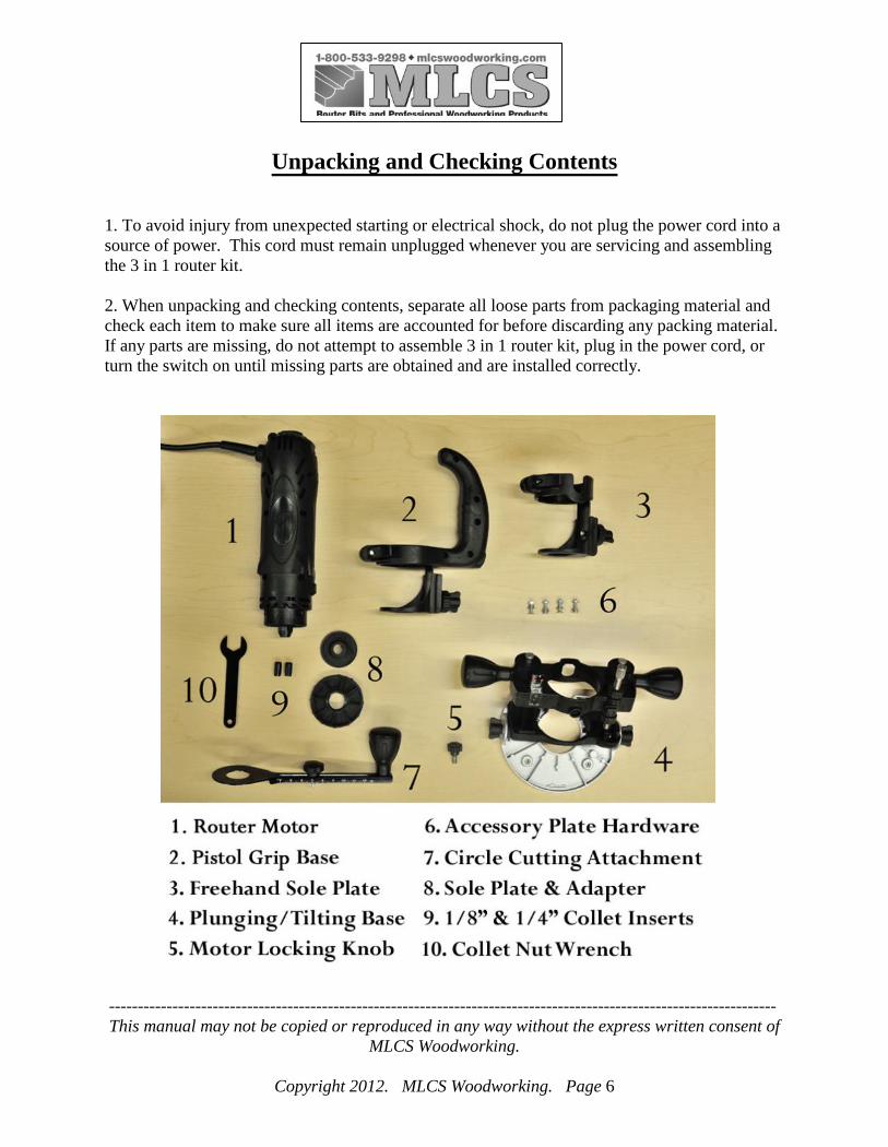
Unpacking and Checking Contents
1. To avoid injury from unexpected starting or electrical shock, do not plug the power cord into asource of power. This cord must remain unplugged whenever you are servicing and assemblingthe 3 in 1 router kit.
2. When unpacking and checking contents, separate all loose parts from packaging material andcheck each item to make sure all items are accounted for before discarding any packing material.If any parts are missing, do not attempt to assemble 3 in 1 router kit, plug in the power cord, orturn the switch on until missing parts are obtained and are installed correctly.

--------------------------------------------------------------------------------------------------------------------This manual may not be copied or reproduced in any way without the express written consent of
MLCS Woodworking.
Copyright 2012. MLCS Woodworking. Page 7
Assembly and Adjustments
Function DescriptionThis tool can be used as a router/edge trimmer or as cut-out tool, when different accessories areinstalled.
Caution! Do not use this tool for drilling holes. It is not intended to be used as a drill.
ON/OFF switch:
The power switch is located near the top of the motor housing. The power is turned on bysliding the power switch upward. Sliding the power switch downward interrupts the power andturns the tool off.
WARNING! Never use the tool if its switch cannot turn it on or off smoothly.
WARNING! Never use tool without the motor installed in the freehand sole plate, pistolgrip handle or plunging/tilting router base.
HIGH / LOW SPEED switch:
The Marvel 42 has two-speed settings. There is a sliding switch on the top of the motor housingto switch between the two speeds. Changing speeds should only be done with the powerswitched off.

--------------------------------------------------------------------------------------------------------------------This manual may not be copied or reproduced in any way without the express written consent of
MLCS Woodworking.
Copyright 2012. MLCS Woodworking. Page 8
Changing Collet Inserts:
The Marvel 42 is supplied with both 1/8” and 1/4” collet inserts. To change the collet insert,loosen and remove the collet nut and insert the desired collet for the bit you intend to install inthe router. Replace the collet nut but do not tighten it fully unless there is a router bit insertedinto the collet as it is possible to permanently distort the collet insert doing this. This could makeinserting bits into the collet difficult or cause you to need to replace the collet insert.
Inserting A Router Bit into the Collet:
With the collet nut loose, slide the router bit into the collet insert. Make sure that you have atleast 3/4” of the router bit shank inserted into the collet. Do not bottom out the bit in the collet. Ifyou insert the shank to the bottom of the collet bore, make sure to pull it out at least 1/16” to 1/8”to allow the collet insert to properly secure the router bit in the collet. There is a button on themotor housing that will lock the spindle to allow you to tighten and loosen the collet nut usingthe supplied wrench. It will be necessary for the spindle to rotate until the spindle lock pinengages the locking hole on the spindle. Before tightening the bit, make sure the flutes of the bitare completely visible outside the collet. Otherwise, it can result in broken bits and possibleinjury. The power cord should be unplugged from the power source when making bit changes toprevent the router from being turned on by accident.
--------------------------------------------------------------------------------------------------------------------This manual may not be copied or reproduced in any way without the express written consent of
MLCS Woodworking.
Copyright 2012. MLCS Woodworking. Page 9
WARNING! Never use dull or damaged bits. Damaged bits can break without warning.Dull bits may overload the motor, cut slowly and are difficult to control. They will alsooverheat and possibly break.
Operations
1. Before operation:1) Before turning the tool ON, check to make sure bit and all accessories fasteners are
securely tightened.2) Avoid cutting your fingers. Make sure all of your fingers are far back from the work-
piece before operation. Keep your hand far away from moving parts.3) Turn off all circuit breakers and remove all fuses in the work area when cutting into walls
or blind areas.4) Always set the depth guide to the appropriate depth. Use tool with the depth guide plate
against the work surface for better control of the tool.5) Before starting the tool, make sure that the bit does not touch the work piece.6) Before cutting the work-piece, let the tool turn for a while without load.
2. During operation:1) Always hold the tool with two hands during start-up and operation. When starting, motor
torque will cause the tool to twist.2) Always make sure the work- piece is free of nails and other foreign objects. If the bit
strikes a nail it will jump sideways and possibly break.3) WARNING! Do not attempt to make cutouts around an opening which has live
electrical wires. If a live wire is contacted, the bit could conduct the electric current tothe tool, creating an electric shock hazard for the operator. Always hold the tool by itsinsulated housing when working in area where there is a possibility of contacting electricwires. Always wear eye protection when operating this tool.
4) When cutting drywall electrical outlet openings, using the outlet as a guide, always cut ina counter clockwise direction. The natural tendency of the tool to pull to the left willcause a "hugging” action toward the outlet box, resulting in a neater cut. (Note: Exceptfor cutting around outlet boxes in drywall, always cut in a clock wise direction).CAUTION! The fine dust produced by cutting glass-fiber, expended compoundmaterials, etc., can shorten the tool life.
3. After operation:1) When the cut is complete, turn the tool OFF, wait until it comes to a complete stop and
remove it from the work-piece.
--------------------------------------------------------------------------------------------------------------------This manual may not be copied or reproduced in any way without the express written consent of
MLCS Woodworking.
Copyright 2012. MLCS Woodworking. Page 10
2) Never lay the tool down until the tool comes to a complete stop. A spinning bit can comein contact with the ground surface and the workbench and pull it out of your control.
3) Never touch the bit immediately after use. The bit may be too hot to be handled withyour hand and may burn your fingers.
4. Working procedure:
Before attempting to work on an actual project, make a few practice cuts on somescraps of material which are the same type of material as used in your actual projectto see how the cutters will work in that material and make any necessaryadjustments to the cutting depth or motor speed.
Freehand Routing:
Use the router base with small router bits to perform various freehand routing projects.Insert the appropriate size collet (1/8” or 1/4") for the router bit you will be using. Install therouter bit and securely tighten it. Adjust the router base height to the correct routing depth.Before turning the switch ON, make sure the router bit is not in contact with anything. Holdingthe two height adjusting knobs with both hands, carefully lower the bit onto the work-piece andguide the bit around the stock in a clockwise direction.
Cutting a Straight Line with a Straight Edge Guide:
To cut a straight line, you can use a straight edge template to guide the router base. Draw astraight line on the work-piece where you wish to make the cut. Draw a second straight lineparallel to the cut line back into the work-piece at the distance between the router base (flat side)and the router bit. Clamp the straight edge guide onto the stock at the secondary line. Place theflat side of the router base against the straight edge with the bit near the start of the cutting line.Turn the switch ON while firmly holding the tool. Slide the router plate against the straight edgewhile making the cut.
Cutting Curved Line with a Template:
To cut a curved line, you can use a curved template to guide the router base. Make a templatefrom hard board or other similar material to the shape you required. Note: Radius of curve mustbe greater than 2 1/2" for router base to properly follow the curved template. Mark the locationof cut to be made. Mark the work-piece approximately 2 1/16" back into the work-piece (awayfrom the cutting line). Clamp or use double sided tape to secure the template onto the work-piecethat is to be cut. Place the curved portion of the router base against the template with the bit nearthe start of the cutting line.
--------------------------------------------------------------------------------------------------------------------This manual may not be copied or reproduced in any way without the express written consent of
MLCS Woodworking.
Copyright 2012. MLCS Woodworking. Page 11
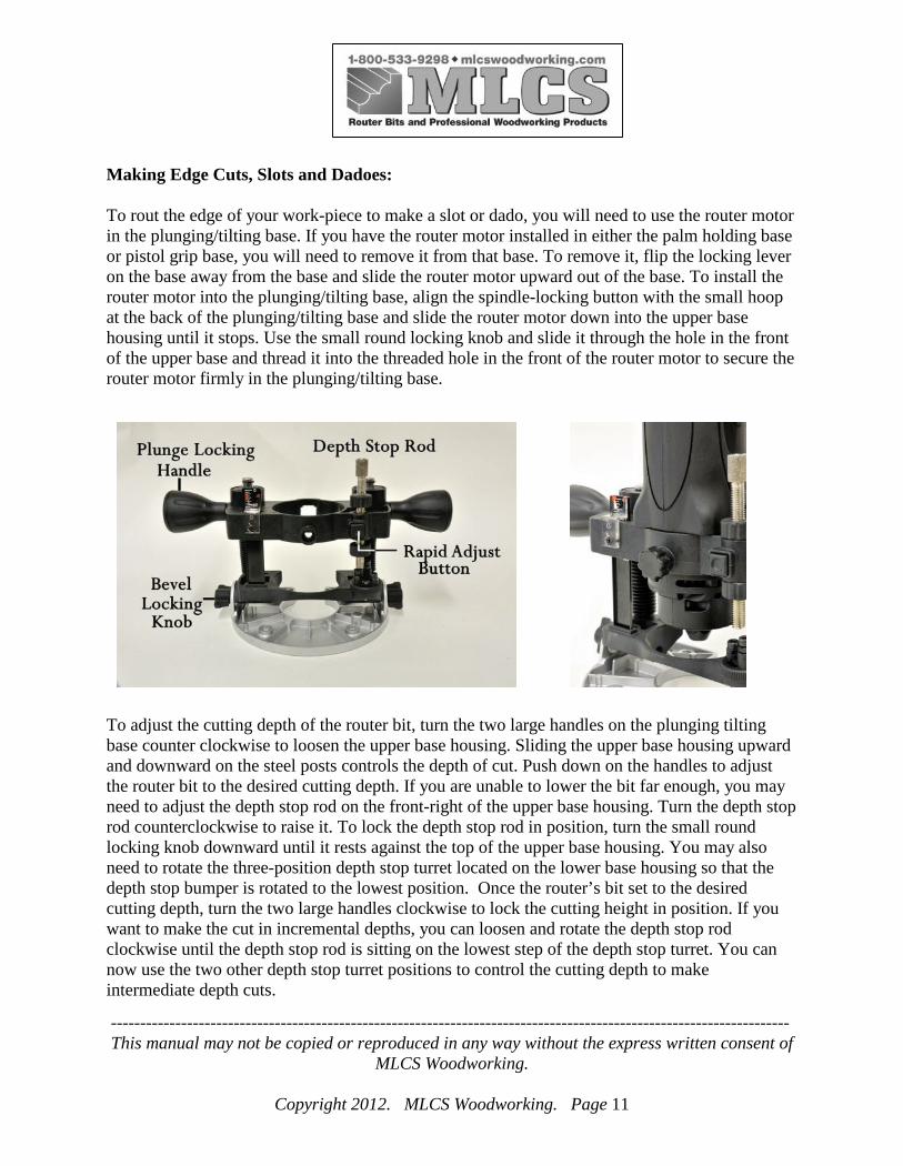
Making Edge Cuts, Slots and Dadoes:
To rout the edge of your work-piece to make a slot or dado, you will need to use the router motorin the plunging/tilting base. If you have the router motor installed in either the palm holding baseor pistol grip base, you will need to remove it from that base. To remove it, flip the locking leveron the base away from the base and slide the router motor upward out of the base. To install therouter motor into the plunging/tilting base, align the spindle-locking button with the small hoopat the back of the plunging/tilting base and slide the router motor down into the upper basehousing until it stops. Use the small round locking knob and slide it through the hole in the frontof the upper base and thread it into the threaded hole in the front of the router motor to secure therouter motor firmly in the plunging/tilting base.
To adjust the cutting depth of the router bit, turn the two large handles on the plunging tiltingbase counter clockwise to loosen the upper base housing. Sliding the upper base housing upwardand downward on the steel posts controls the depth of cut. Push down on the handles to adjustthe router bit to the desired cutting depth. If you are unable to lower the bit far enough, you mayneed to adjust the depth stop rod on the front-right of the upper base housing. Turn the depth stoprod counterclockwise to raise it. To lock the depth stop rod in position, turn the small roundlocking knob downward until it rests against the top of the upper base housing. You may alsoneed to rotate the three-position depth stop turret located on the lower base housing so that thedepth stop bumper is rotated to the lowest position. Once the router’s bit set to the desiredcutting depth, turn the two large handles clockwise to lock the cutting height in position. If youwant to make the cut in incremental depths, you can loosen and rotate the depth stop rodclockwise until the depth stop rod is sitting on the lowest step of the depth stop turret. You cannow use the two other depth stop turret positions to control the cutting depth to makeintermediate depth cuts.

--------------------------------------------------------------------------------------------------------------------This manual may not be copied or reproduced in any way without the express written consent of
MLCS Woodworking.
Copyright 2012. MLCS Woodworking. Page 12
Adjusting the Depth Stop on the Plunging/Tilting Base:
The depth stop is located on the front right of the plunging/tilting base. It allows you to preset acutting depth and plunge the router bit to the preset depth. The router should be turned off beforeattempting to adjust the depth stop position. To adjust the position the upper and lower lockingknobs need to be backed off the upper base housing to allow the depth rod to be turned. Thebutton in the middle of the upper housing where the rod threads through allows for rapidadjustment by disengaging the threads from the rod. To make rapid changes, push the button inand position the rod close to the final position. Release the button and fine tune the position ofthe depth rod by turning the rod upward or downward until you have it adjusted to the exactposition you need it. To secure it in place, turn the upper and lower locking knobs against theupper base housing, which will prevent any movement during use. Do not attempt to adjust thedepth stop rod position while the router is running.
Using Template Guide Bushings with the Marvel 42 and Plunging Base:
The aluminum base is molded with four through holes and hex nut recesses in it to allow you touse a sub base on the bottom of the aluminum base. There are also four screws and hex nutslocated in the small parts bag in the compartment on the case lid with the clear plastic door overit. This will allow you to use the MLCS #9339 Universal Base Plate on the Marvel router anduse Porter Cable style template guide bushings with this base. Align the (4) recessed slots in theaccessory baseplate with the (4) holes in the aluminum base. Use the tapered washers included inthe #9339 Universal Baseplate with the (4) machine screws included with the Marvel 40 andsecure the baseplate to the base with the (4) hex nuts. The hex nuts will fit into the recess to keepthem from spinning as the baseplate screws are tightened.
--------------------------------------------------------------------------------------------------------------------This manual may not be copied or reproduced in any way without the express written consent of
MLCS Woodworking.
Copyright 2012. MLCS Woodworking. Page 13
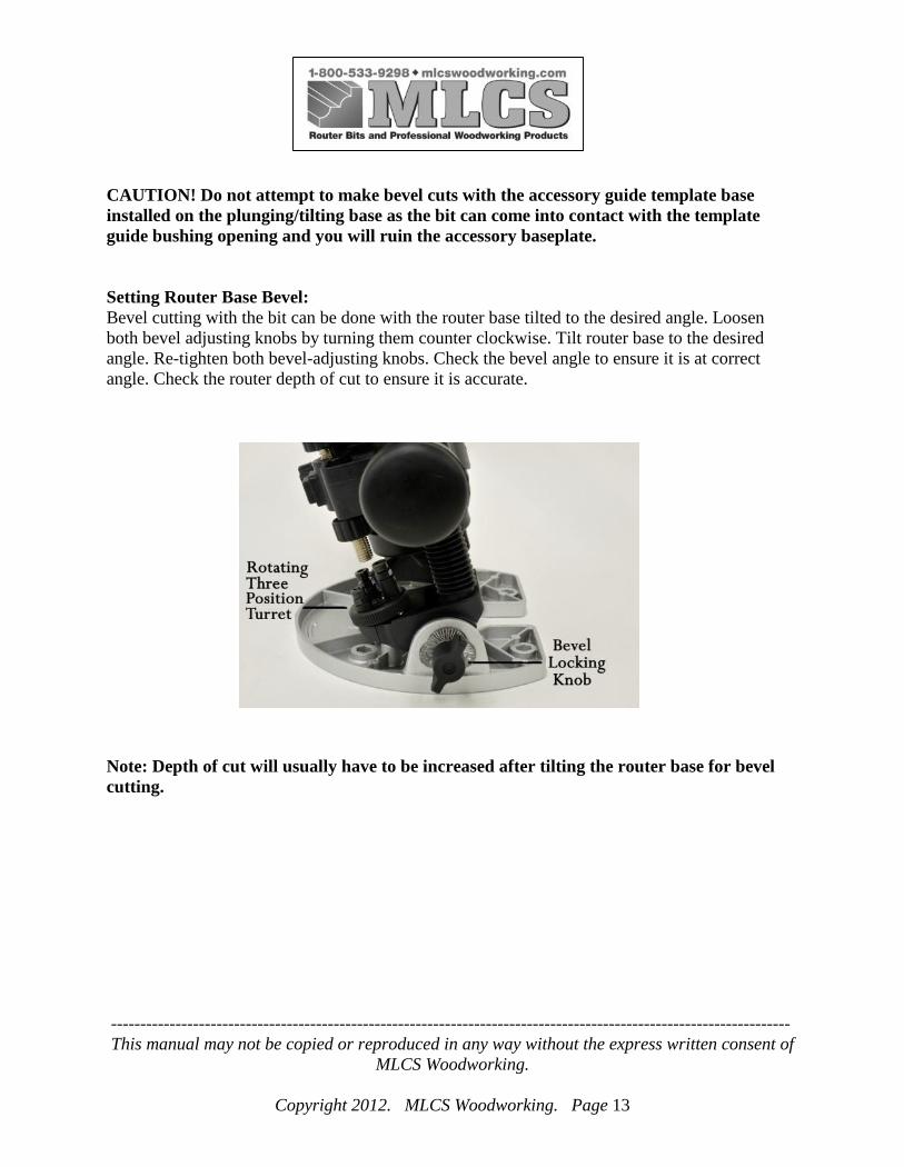
CAUTION! Do not attempt to make bevel cuts with the accessory guide template baseinstalled on the plunging/tilting base as the bit can come into contact with the templateguide bushing opening and you will ruin the accessory baseplate.
Setting Router Base Bevel:Bevel cutting with the bit can be done with the router base tilted to the desired angle. Loosenboth bevel adjusting knobs by turning them counter clockwise. Tilt router base to the desiredangle. Re-tighten both bevel-adjusting knobs. Check the bevel angle to ensure it is at correctangle. Check the router depth of cut to ensure it is accurate.
Note: Depth of cut will usually have to be increased after tilting the router base for bevelcutting.

--------------------------------------------------------------------------------------------------------------------This manual may not be copied or reproduced in any way without the express written consent of
MLCS Woodworking.
Copyright 2012. MLCS Woodworking. Page 14
Installing the Circle Cutting Attachment:
The circle cutting attachment will allow you cut circles from a minimum diameter of 4” to amaximum diameter of 12”. The circle cutting attachment will require using the palm held base ifyou want to hold the router motor with the palm of your hand or the t-handle base if you want toguide the router by holding the pistol grip base. Unscrew the sole plate from the D-shaped ring toremove the mounting hardware from the circle cutting attachment. Place the D-shaped ring intothe top side of the base you plan to use, aligning the flat edge on the nut with the flat edge on thethrough hole in the base and with the threads protruding through the bottom of the base. Placethe circle cutter arm over the exposed threads and secure to the base by threading the sole plateback onto the D-shaped ring. Insert the router motor into the base and lock in place at the desiredheight by flipping the locking lever on the base to secure the router in the base. The cut should bemade by making multiple passes, adjusting the cutting depth each time until the final cut willallow you to completely cut through the stock thickness.
Making a Circle Cut:
To make a circle, drill a 1/8” diameter hole to a depth of 9/32” in the center of the circle for thepivot pin to be inserted into. Adjust the pivot pin to position on the circle-cutting jig using thescale on the side of the circle-cutting jig. Turn the knob clockwise to lock the pivot pin at thedesired diameter.
The cut is made by inserting the pivot pin into the 1/8” center hole with the router bit and routerheld above the stock. Carefully turn the router on and slowly plunge the rotating router bit intothe stock until the sole plate sits squarely on the stock. With one hand holding the router or pistolgrip handle and the other hand on the ball knob on the end opposite the router, slowly rotate therouter around the pivot pin until you have completed a full circle around the pivot point. Turn therouter off and allow the bit to come to a full stop before removing the router bit from the cut.Readjust the cutting depth and repeat until you have completed making the circular cut out.

--------------------------------------------------------------------------------------------------------------------This manual may not be copied or reproduced in any way without the express written consent of
MLCS Woodworking.
Copyright 2012. MLCS Woodworking. Page 15
Installing Freehand Sole Plate and Pistol Grip Base:
To install the router motor into the freehand sole plate base or pistol grip base, make sure thelocking lever is released by flipping it away from the base. Align the spindle-locking button withthe U-shaped recess in the upper base and slide the router motor down into the upper base housinguntil it stops. Flip the locking lever against the base to lock the motor into the base.
WARNING! Do not use the freehand sole plate or pistol grip base for making “standard”router cuts. These bases are designed to be used with the circle cutting accessory or whenusing the Marvel 40 to cut electrical box openings in drywall. Limited control with thisaccessory could cause you to loose control and increase the chance of serious injury. Use ahigh speed steel spiral bit that will allow you to plunge cut through the drywall when usingthe tool to make the cut outs.
Adjusting the Cutter Depth using the Freehand Sole and Pistol Grip Bases:
Loosen the butterfly knob on the height adjustment wheel. Use the height adjustment wheel toposition the bit to the required cutting depth. Tighten the butterfly knob to lock the cutting depthat your desired position. Before starting to cut, you should re-check bit depth and make sure soleplate is securely tightened. Re-check the collect to make sure the bit is securely fastened.
--------------------------------------------------------------------------------------------------------------------This manual may not be copied or reproduced in any way without the express written consent of
MLCS Woodworking.
Copyright 2012. MLCS Woodworking. Page 16
Cutting Out Openings for Electrical Boxes:
DO NOT use excessive pressure and fast speed while cutting. The motor speed switchshould be set to operate on the lower of the two speeds when cutting drywall.
CAUTION! Do not attempt cutting around outlet boxes in drywall until:1) You have either turned the breaker OFF or removed the fuses that interrupt all electricity
in the vicinity of the electric box.2) You have read the instructions and understand the correct procedure for cutting out an
opening in drywall.
Before installing drywall, push the electrical wires to the back of the box far as possible toreduce the likelihood of the wires being cut by the bit when cutting the opening. Beforeoperation, mark the drywall sheet as close as possible to the center of the box opening. The markshould be made on the side of the drywall that will be facing you. Adjust the depth of cut so thebit will protrude at least 1/16”, but no more than 1/8" beyond the thickness of the drywall.Properly fasten the drywall to the studded wall. With the heel of the base resting against thedrywall and the bit at an angle to the drywall, without touching it, turn the motor on and carefullyplunge the bit through the drywall at the mark indicating the center of the box. Tilt the base sothat it sits flush on the drywall. Move the bit slowly to the right until you feel the bit contactingthe inside of the box. Pull the bit out far enough to slip it over the edge of the electrical box.Once the bit is outside the electrical box, push it back to full depth beside the outside edge of theelectrical box. Move the tool upward while applying slight pressure toward the center of the box.When you feel the bit reach the top right hand corner of the box, move the tool to the left whileapplying slight pressure downward toward the center of the box. Continue moving the toolaround the box in a counter clockwise direction while maintaining slight pressure toward thecenter of the box. When the box cutout is complete, turn the tool OFF and remove it from thecutout. The rotating cutting action of the bit will cause a slight pull to the left when cutting.Natural variations in the structure of wood will cause the bit to wander. When cutting a hole in avertical surface, avoid ending the cut at the bottom of the hole. Always start and end the cut atthe top, so the cutout part will not drop onto the rotating bit. Always turn the tool OFF beforeremoving it from the work-piece.

--------------------------------------------------------------------------------------------------------------------This manual may not be copied or reproduced in any way without the express written consent of
MLCS Woodworking.
Copyright 2012. MLCS Woodworking. Page 17
MAINTENANCE
WARNING! Unplug the tool before changing accessories or bits and making adjustments.
1. Do not clean the tool by using highly volatile liquids such as solvent, gasoline or petroleumproduct, etc, because the chemical substances contained in these liquids may damage the plastic.2. Always keep the tool handle free from oil or grease.3. Always re-tighten collet and all adjustments before starting the tool after a bit or accessoryhas been changed. Loose bits and adjustments can cause unexpected shifting of the tool,resulting in loss of control and injury from the bit or tool being thrown.4. CAUTION! To avoid shock or fire, replace power cord immediately if it is worn or damagedin any way.5. When the carbon brushes have been worn to their limitation, they should be replaced. Bothcarbon brushes should be replaced at the same time.6. WARNING! Use only accessories recommended by MLCS to avoid injury to the operatoror damage to the tool.

--------------------------------------------------------------------------------------------------------------------This manual may not be copied or reproduced in any way without the express written consent of
MLCS Woodworking.
Copyright 2012. MLCS Woodworking. Page 18
Exploded Diagram and Parts List for #9059 Marvel 42
PART NO. PART NAME QTY PART NO. PART NAME QTY PART NO. PART NAME QTY
1 Sole Plate 1 14 Left Handle 1 28 Switch Shockproof Pad 1
2 Locating Sleeve 1 15 Cross Recess Head Screw 16 29 Right Case 1
3 Height Adjustment Wheel 1 16 Left Case 1 30 Right Handle 1
4 Lock Screw 1 17 Strain Relief 1 31 Short Lock Bar 1
5 Lock Spring 1 18 Power Cord 1 32 Brush Spring Washer 2
6 Pin 1 19 Cord Anchor 1 33 Brush 2
7 Spindle Lock Button 1 20 Circuit Board 1 34 Brush Sleeve 2
8 Handle Bracket 1 22 Two Speed Push Switch 1 35 Stator 1
9 Lock Pin 1 23 Power Switch 1 36 Rotor 1
10 Spring 1 24 Bearing Sleeve 1 37 Front Bearing 1
11 Lock Pin Washer 1 25 Connecting Switch Cord 1 38 Collet (1/4" and 1/8") 1
12 Lock Lever 1 26 Switch 1 39 Collet Nut 1
13 Round Pin 1 27 Rear Bearing 1 40 Hexagon Nut 1

--------------------------------------------------------------------------------------------------------------------This manual may not be copied or reproduced in any way without the express written consent of
MLCS Woodworking.
Copyright 2012. MLCS Woodworking. Page 19
Exploded Diagram and Parts List for the Plunging/Tilting Base
PART NO. PART NAME QTY PART NO. PART NAME QTY PART NO. PART NAME QTY
1 Router Base 1 12 Lifting Spring 2 22 Nut 2
2 M4 Hexagon Nut 2 13 Locking Block 1 23 Router Base (upper) 1
3 Locking Disc 2 14 Spring 1 24 M4x20 Screw 1
4 Locking Screw 2 15 Handle 2 25 M4x16 Screw 1
6 M4x8 Screw 3 16 Locking Copper Bead 2 26 M4x10 Screw 1
7 Router Base (middle) 1 17 Ruler-Indicating Plate 1 27 Set Screw 1
8 M4 Hexagon Nut 4 18 M5 Square Nut 2 28 Adjusting Wheel 1
9 Ruler 1 19 Guide Bushing 2 29 Bushing 2
10 Guide Rod 2 20 C-Ring 2 30 5mm Ball Bearing 1
11 Dust Cover 2 21 Lifting Rod 1 31 Spring 1

--------------------------------------------------------------------------------------------------------------------This manual may not be copied or reproduced in any way without the express written consent of
MLCS Woodworking.
Copyright 2012. MLCS Woodworking. Page 20
Exploded Diagram and Parts List for the Freehand Sole Plate
Part No. Part Name Qty1 Sole Plate Sleeve 12 Lock Wrench 13 Round Pin 14 Sole Plate Bracket 15 Sole Plate 16 Locating Sleeve 17 Regulating Wheel 18 Clamping Screw 19 Short Lock Bar 1

--------------------------------------------------------------------------------------------------------------------This manual may not be copied or reproduced in any way without the express written consent of
MLCS Woodworking.
Copyright 2012. MLCS Woodworking. Page 21
Exploded Diagram and Parts List for Circle Cutting Attachment
Part No. Part Name Qty1 Guide Base Bottom 12 Circle Cutting Guide Plate 13 Guide Base Upper 14 Distance Lock Screw 15 Cup Handle 16 5mm Flat Washer 17 Handle Bushing 18 5mm Flat Washer 19 5mm Spring Washer 1
10 M5 Hexagon Nut 111 M6 Square Nut 1