Embed Size (px)
Citation preview
www.mellanox.com
MLNX_VPI for WindowsInstallation Guide

Mellanox Technologies350 Oakmead Parkway, Suite 100 Sunnyvale, CA 94085 U.S.A.www.mellanox.comTel: (408) 970-3400Fax: (408) 970-3403
Mellanox Technologies, Ltd.PO Box 586 Hermon BuildingYokneam 20692IsraelTel: +972-4-909-7200Fax: +972-4-959-3245
© Copyright 2010. Mellanox Technologies, Inc. All Rights Reserved.Mellanox®, BridgeX®, ConnectX®, InfiniBlast®, InfiniBridge®, InfiniHost®, InfiniRISC®, InfiniScale®, InfiniPCI®, and Virtual Protocol Interconnect® are registered trademarks of Mellanox Technologies, Ltd. CORE-Direct®, FabricIT, and PhyX are trademarks of Mellanox Technologies, Ltd.
All other marks and names mentioned herein may be trademarks of their respective companies.
Document Number: 3217
Rev 2.1.1
Mellanox Technologies2
NOTE:
THIS INFORMATION IS PROVIDED BY MELLANOX FOR INFORMATIONAL PURPOSES ONLY AND ANY EXPRESS OR IMPLIED WARRANTIES, INCLUDING, BUT NOT LIM-ITED TO, THE IMPLIED WARRANTIES OF MERCHANTABILITY AND FITNESS FOR A PARTICULAR PURPOSE ARE DISCLAIMED. IN NO EVENT SHALL MELLANOX BE LIA-BLE FOR ANY DIRECT, INDIRECT, INCIDENTAL, SPECIAL, EXEMPLARY, OR CONSE-QUENTIAL DAMAGES (INCLUDING, BUT NOT LIMITED TO, PROCUREMENT OF SUBSTITUTE GOODS OR SERVICES; LOSS OF USE, DATA, OR PROFITS; OR BUSINESS INTERRUPTION) HOWEVER CAUSED AND ON ANY THEORY OF LIABILITY, WHETHER IN CONTRACT, STRICT LIABILITY, OR TORT (INCLUDING NEGLIGENCE OR OTHERWISE) ARISING IN ANY WAY OUT OF THE USE OF THIS HARDWARE, EVEN IF ADVISED OF THE POSSIBILITY OF SUCH DAMAGE.
Rev 2.1.1
Mellanox Technologies 3
Table of Contents
Chapter 1 Introduction 41.1 Scope 41.2 Web Page and Documentation 41.3 Hardware and Software Requirements 4
1.3.1 Hardware Requirements 41.3.2 Software Requirements 5
Chapter 2 Identifying Mellanox Adapters on Your Machine 6Chapter 3 Downloading MLNX_VPI 8Chapter 4 Installing MLNX_VPI 9
4.1 Attended Installation 94.2 Unattended Installation 13
Chapter 5 Installation Results 14Chapter 6 Assigning Port IP After Installation 15Chapter 7 Port Protocol Configuration 18Chapter 8 Advanced Configuration for InfiniBand Driver 20
8.1 WDS Installation 208.2 Modifying Configuration After Installation 25
8.2.1 Modifying Mellanox HCA Configuration 258.2.2 Modifying IPoIB Configuration 25
Chapter 9 Advanced Configuration for Ethernet Driver 269.1 Displaying Adapter Related Information 269.2 Creating a Load Balancing and Fail-Over (LBFO) Bundle 279.3 Creating a Port VLAN 32
9.3.1 Removing a Port VLAN 349.4 Configuring Advanced Features 35
9.4.1 Receive Rings in RSS Mode 37
Chapter 10 Uninstalling MLNX_VPI 40
IntroductionRev 2.1.1
Mellanox Technologies4
1 Introduction
1.1 Scope
This document describes how to install and test MLNX_VPI for Windows on a single host machine with Mellanox hardware installed.
1.2 Web Page and Documentation
To access the MLNX_VPI Windows Web page, please visit http://www.mellanox.com and navi-gate to Products--> InfiniBand & VPI Software/Drivers --> MLNX_VPI_Windows. The page pro-vides access to the SW package and to reference documentation such as release notes, user manuals, FAQ, troubleshooting, and archive.
After installing MLNX_VPI (see the installation section below), you will find release notes and other documentation under the installation directory (default: Program Files\ Mellanox\ MLNX_VPI\ Documentation\”.
1.3 Hardware and Software Requirements
1.3.1 Hardware Requirements
Required Disk Space for Installation• 100 MB
Platforms
MLNX_VPI SW will install the appropriate drivers according the Mellanox network card capabil-ity, please refer to the list below:
VPI• Mellanox ConnectX VPI (MT25408) - PCIe 2.0 IB SDR / 10GigE Network Adapter• Mellanox ConnectX VPI (MT25418) - PCIe 2.0 2.5GT/s, IB DDR / 10GigE Network Adapter• Mellanox ConnectX VPI (MT26418) - PCIe 2.0 5GT/s, IB DDR / 10GigE Network Adapter• Mellanox ConnectX VPI (MT26488) - PCIe 2.0 5GT/s, IB DDR / 10GigE Network Adapter• Mellanox ConnectX VPI (MT26428) - PCIe 2.0 5GT/s, IB QDR / 10GigE Network Adapter• Mellanox ConnectX VPI (MT26438) - PCIe 2.0 5GT/s, IB QDR / 10GigE Network Adapter
IB Only• InfiniHost (MT23108) - Mellanox InfiniBand HCA• InfiniHost (MT25208) - Mellanox InfiniBand HCA for PCI Express• InfiniHost III Ex (MT25218) - Mellanox InfiniBand HCA for PCI Express• InfiniHost III Lx (MT24204) - Mellanox InfiniBand HCA for PCI Express
Rev 2.1.1
Mellanox Technologies 5
• InfiniHost III Lx (MT25204) - Mellanox InfiniBand HCA for PCI Express
Ethernet Only• Mellanox ConnectX EN (MT25448) - PCIe 2.0 2.5GT/s, 10GigE Ethernet Adapter• Mellanox ConnectX EN (MT25458) - PCIe 2.0 2.5GT/s, 10GigE 10GBaseT Ethernet Adapter• Mellanox ConnectX EN (MT26448) - PCIe 2.0 5GT/s, 10GigE Ethernet Adapter• Mellanox ConnectX EN (MT26458) - PCIe 2.0 5GT/s, 10GigE 10GBaseT Ethernet Adapter• Mellanox ConnectX EN (MT26468) - PCIe 2.0 5GT/s, 10GigE Ethernet Adapter• Mellanox ConnectX EN (MT26478) - PCIe 2.0 5GT/s, 40GigE Ethernet Adapter
1.3.2 Software Requirements
Operating Systems• Windows Server 2003• Windows Server 2008• Windows Server 2008-R2
Pre-installed Software
For Windows Server 2003 only: Prior to installing MLNX_VPI on your machine, the NDIS API, version 5.2 must be installed.
Installer Privileges
On Windows Server 2003: The installation requires administrator privileges on the machine.
On Windows Server 2008: The installation of MLNX_VPI requires elevated administrator privi-leges when UAC (User Account Control) is activated. To set elevated administrator privileges click start-->Programs-->Accessories, then right-click over "Command Prompt" and select "Run as administrator". (To activate/de-activate UAC, click start-->Settings-->Control Panel-->User Accounts.)
Identifying Mellanox Adapters on Your MachineRev 2.1.1
Mellanox Technologies6
2 Identifying Mellanox Adapters on Your Machine
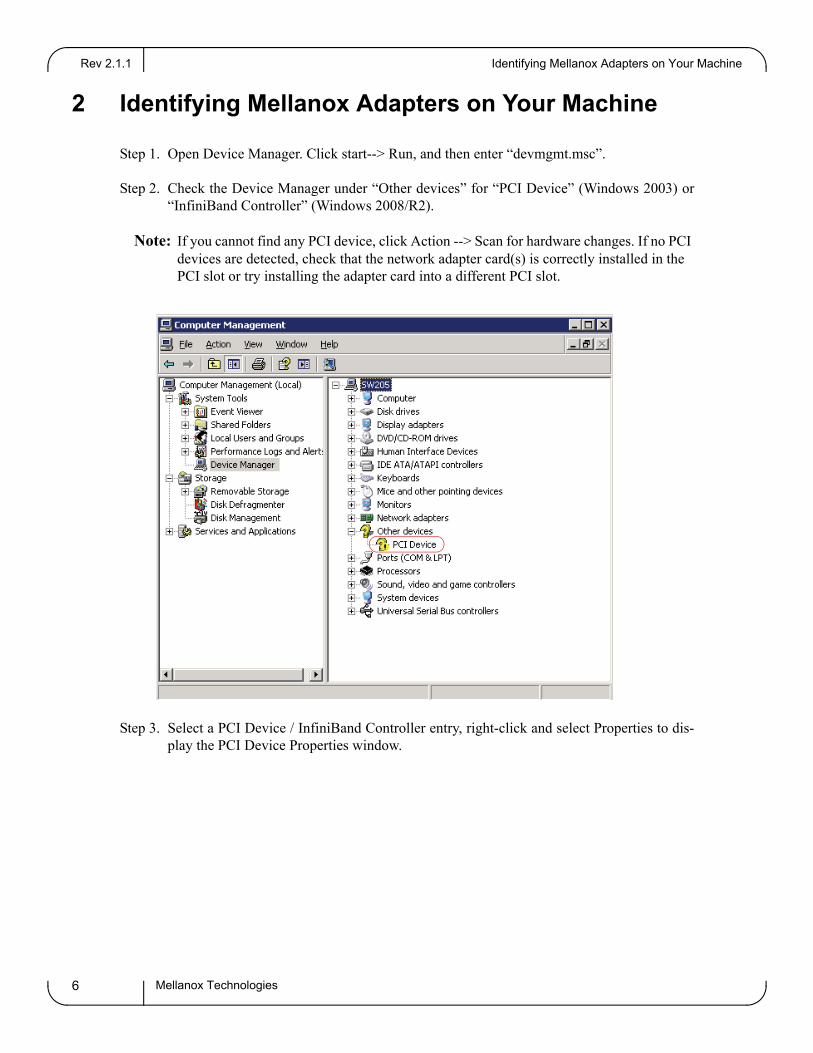
Step 1. Open Device Manager. Click start--> Run, and then enter “devmgmt.msc”.
Step 2. Check the Device Manager under “Other devices” for “PCI Device” (Windows 2003) or “InfiniBand Controller” (Windows 2008/R2).
Note: If you cannot find any PCI device, click Action --> Scan for hardware changes. If no PCI devices are detected, check that the network adapter card(s) is correctly installed in the PCI slot or try installing the adapter card into a different PCI slot.
Step 3. Select a PCI Device / InfiniBand Controller entry, right-click and select Properties to dis-play the PCI Device Properties window.
Rev 2.1.1
Mellanox Technologies 7
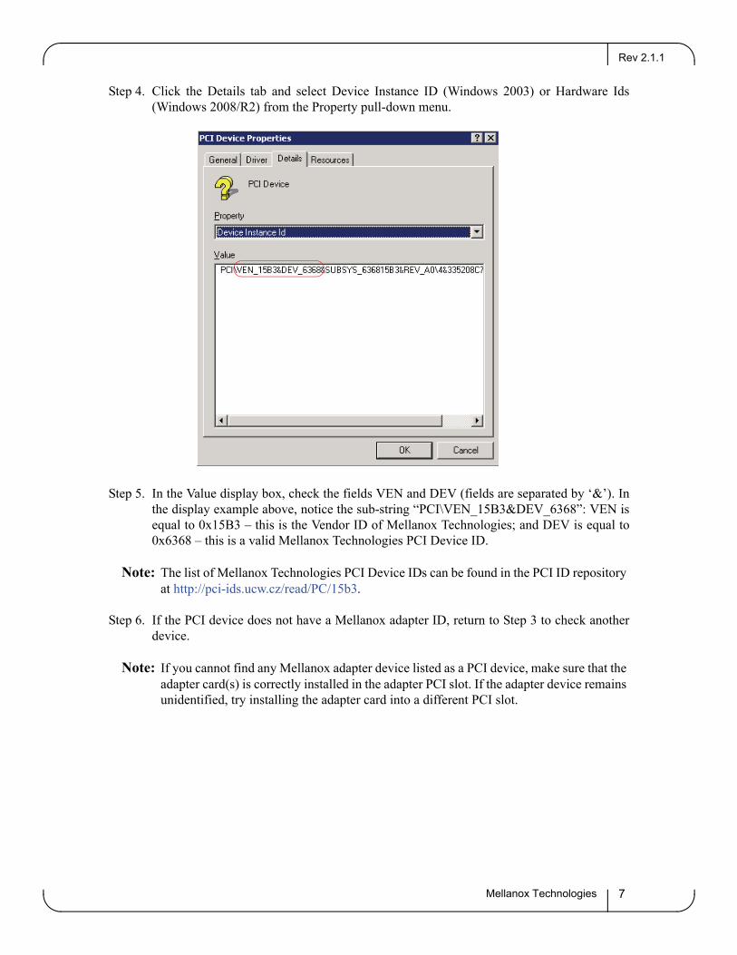
Step 4. Click the Details tab and select Device Instance ID (Windows 2003) or Hardware Ids (Windows 2008/R2) from the Property pull-down menu.
Step 5. In the Value display box, check the fields VEN and DEV (fields are separated by ‘&’). In the display example above, notice the sub-string “PCI\VEN_15B3&DEV_6368”: VEN is equal to 0x15B3 – this is the Vendor ID of Mellanox Technologies; and DEV is equal to 0x6368 – this is a valid Mellanox Technologies PCI Device ID.
Note: The list of Mellanox Technologies PCI Device IDs can be found in the PCI ID repository at http://pci-ids.ucw.cz/read/PC/15b3.
Step 6. If the PCI device does not have a Mellanox adapter ID, return to Step 3 to check another device.
Note: If you cannot find any Mellanox adapter device listed as a PCI device, make sure that the adapter card(s) is correctly installed in the adapter PCI slot. If the adapter device remains unidentified, try installing the adapter card into a different PCI slot.
Downloading MLNX_VPIRev 2.1.1
Mellanox Technologies8
3 Downloading MLNX_VPI
Follow these steps to download the appropriate MSI to your machine.
Step 1. Verify the machine architecture.a. Open a CMD console (Click start-->Run and enter CMD).b. enter the following command:
> echo %PROCESSOR_ARCHITECTURE%
On an x86 (32-bit) machine, the output will be “x86”. On an x64 (64-bit) machine, the output will be “AMD64” or “Intel 64”.
Step 2. Go to the MLNX_VPI for Windows Web page at http://www.mellanox.com --> Products --> Software/Drivers --> InfiniBand & VPI SW/Drivers --> Mellanox WinOF for Windows (MLNX_WinOF_VPI)
Step 3. Download the appropriate MSI according to the architecture of your machine (see Step 1). The MSI’s name has the format MLNX_WinOF_VPI_<arch>_<version>.msi, where arch can be either x86 or x64.
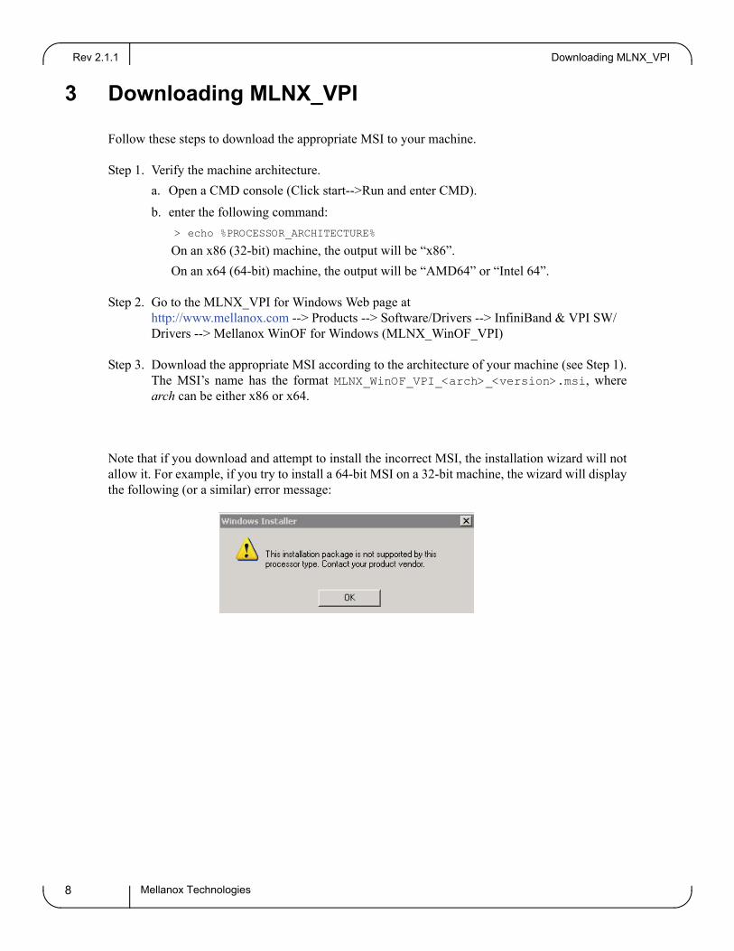
Note that if you download and attempt to install the incorrect MSI, the installation wizard will not allow it. For example, if you try to install a 64-bit MSI on a 32-bit machine, the wizard will display the following (or a similar) error message:
Rev 2.1.1
Mellanox Technologies 9
4 Installing MLNX_VPI
This sections provides instructions for two types of installation:• “Attended Installation” (see below)
An attended installation is an installation procedure that requires frequent user intervention.• “Unattended Installation” on page 13
An unattended installation is an automated installation procedure that requires no user intervention.
4.1 Attended Installation
Note: The installation requires administrator privileges on the machine.
Double click the MSI and follow the GUI instructions to install MLNX_VPI.
The following is an example of a MLNX_VPI x64 installation session.
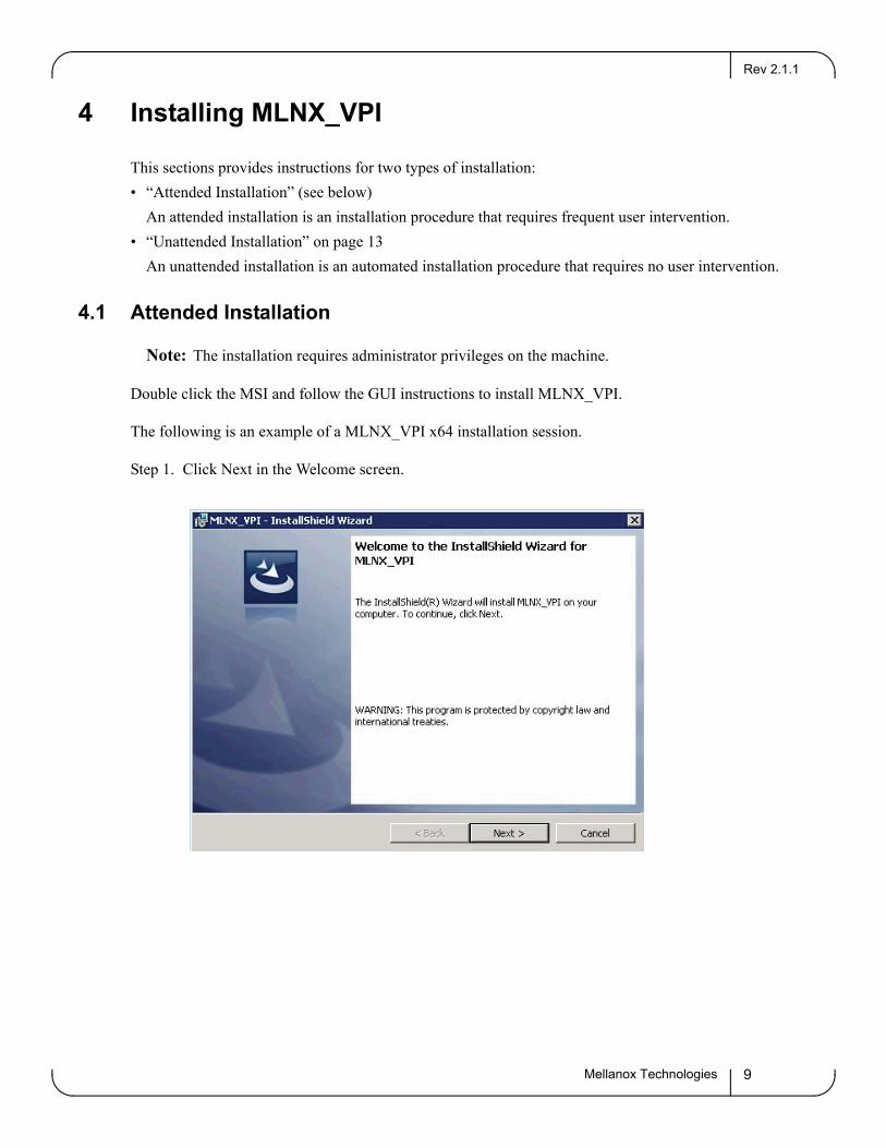
Step 1. Click Next in the Welcome screen.
Installing MLNX_VPIRev 2.1.1
Mellanox Technologies10
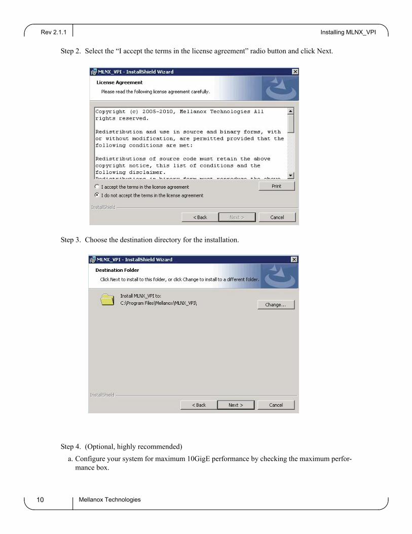
Step 2. Select the “I accept the terms in the license agreement” radio button and click Next.
Step 3. Choose the destination directory for the installation.
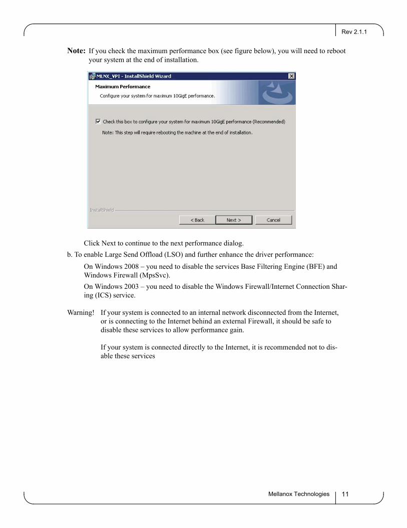
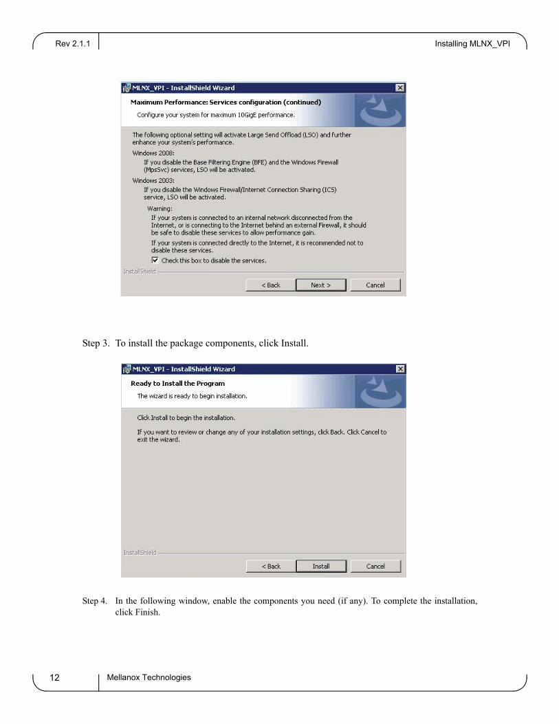
Step 4. (Optional, highly recommended)a. Configure your system for maximum 10GigE performance by checking the maximum perfor-
mance box.
Rev 2.1.1
Mellanox Technologies 11
Note: If you check the maximum performance box (see figure below), you will need to reboot your system at the end of installation.
Click Next to continue to the next performance dialog.b. To enable Large Send Offload (LSO) and further enhance the driver performance:
On Windows 2008 – you need to disable the services Base Filtering Engine (BFE) and Windows Firewall (MpsSvc).On Windows 2003 – you need to disable the Windows Firewall/Internet Connection Shar-ing (ICS) service.
Warning! If your system is connected to an internal network disconnected from the Internet, or is connecting to the Internet behind an external Firewall, it should be safe to disable these services to allow performance gain. If your system is connected directly to the Internet, it is recommended not to dis-able these services
Installing MLNX_VPIRev 2.1.1
Mellanox Technologies12
Step 3. To install the package components, click Install.
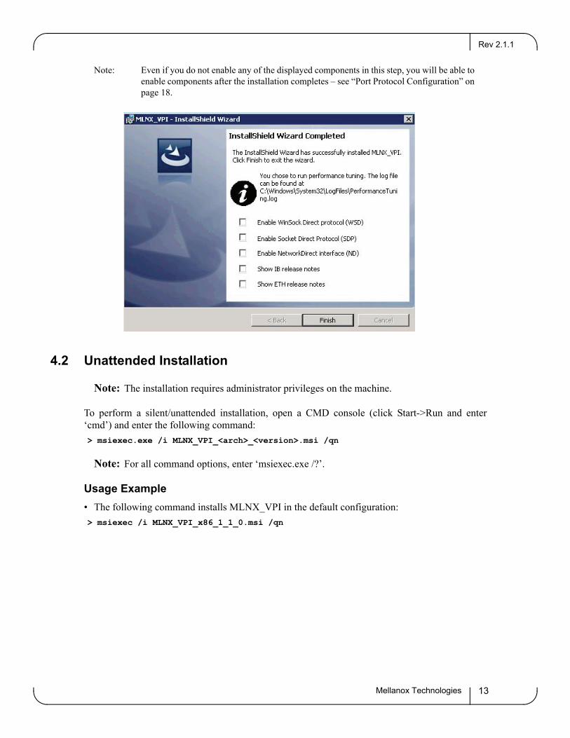
Step 4. In the following window, enable the components you need (if any). To complete the installation, click Finish.
Rev 2.1.1
Mellanox Technologies 13
Note: Even if you do not enable any of the displayed components in this step, you will be able to enable components after the installation completes – see “Port Protocol Configuration” on page 18.
4.2 Unattended Installation
Note: The installation requires administrator privileges on the machine.
To perform a silent/unattended installation, open a CMD console (click Start->Run and enter ‘cmd’) and enter the following command:> msiexec.exe /i MLNX_VPI_<arch>_<version>.msi /qn
Note: For all command options, enter ‘msiexec.exe /?’.
Usage Example• The following command installs MLNX_VPI in the default configuration:> msiexec /i MLNX_VPI_x86_1_1_0.msi /qn
Installation ResultsRev 2.1.1
Mellanox Technologies14
5 Installation Results
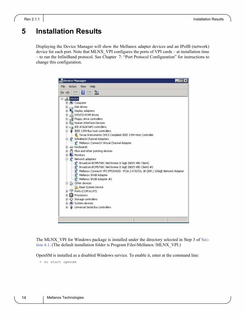
Displaying the Device Manager will show the Mellanox adapter devices and an IPoIB (network) device for each port. Note that MLNX_VPI configures the ports of VPI cards – at installation time – to run the InfiniBand protocol. See Chapter 7: “Port Protocol Configuration” for instructions to change this configuration.
The MLNX_VPI for Windows package is installed under the directory selected in Step 3 of Sec-tion 4.1. (The default installation folder is Program Files\Mellanox \MLNX_VPI.)
OpenSM is installed as a disabled Windows service. To enable it, enter at the command line: > sc start opensm
Rev 2.1.1
Mellanox Technologies 15
6 Assigning Port IP After Installation
By default, your machine is configured to obtain an automatic IP address via a DHCP server. In some cases, the DHCP server may require the MAC address of the network adapter installed in your machine. To obtain the MAC address, open a CMD console and enter the command ‘ipconfig /all’ ; the MAC address is displayed as “Physical Address”.
To assign a static IP addresses to a network port after installation, perform the following steps:
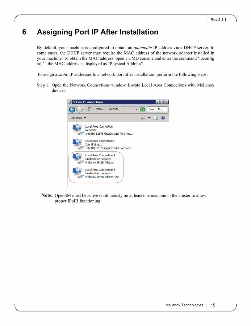
Step 1. Open the Network Connections window. Locate Local Area Connections with Mellanox devices.
Note: OpenSM must be active continuously on at least one machine in the cluster to allow proper IPoIB functioning.
Assigning Port IP After InstallationRev 2.1.1
Mellanox Technologies16
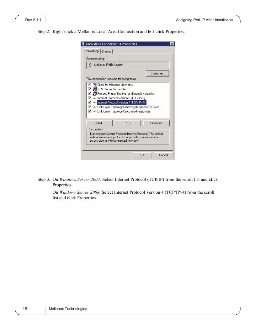
Step 2. Right-click a Mellanox Local Area Connection and left-click Properties.
Step 3. On Windows Server 2003: Select Internet Protocol (TCP/IP) from the scroll list and click Properties.On Windows Server 2008: Select Internet Protocol Version 4 (TCP/IPv4) from the scroll list and click Properties.
Rev 2.1.1
Mellanox Technologies 17
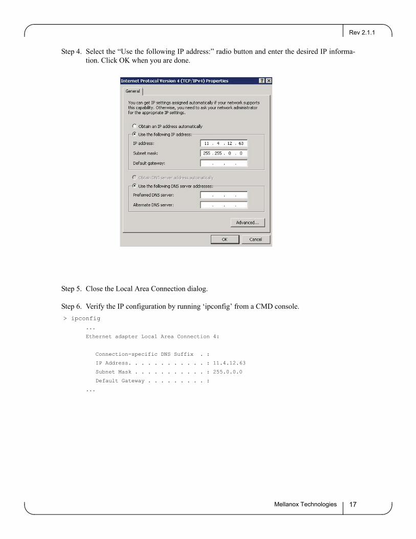
Step 4. Select the “Use the following IP address:” radio button and enter the desired IP informa-tion. Click OK when you are done.
Step 5. Close the Local Area Connection dialog.
Step 6. Verify the IP configuration by running ‘ipconfig’ from a CMD console.> ipconfig
...
Ethernet adapter Local Area Connection 4:
Connection-specific DNS Suffix . :
IP Address. . . . . . . . . . . . : 11.4.12.63
Subnet Mask . . . . . . . . . . . : 255.0.0.0
Default Gateway . . . . . . . . . :
...
Port Protocol ConfigurationRev 2.1.1
Mellanox Technologies18
7 Port Protocol Configuration
After MLNX_VPI installation, it is possible to change the network protocol that runs on each port of VPI adapter cards. Each port can be set to run either InfiniBand or Ethernet.
Note: For dual port adapters only: If you wish to configure InfiniBand on one port and Ethernet on the other port, you must set Port 1 as InfiniBand.
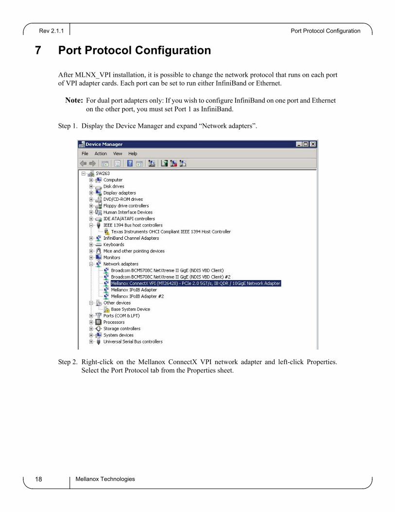
Step 1. Display the Device Manager and expand “Network adapters”.
Step 2. Right-click on the Mellanox ConnectX VPI network adapter and left-click Properties. Select the Port Protocol tab from the Properties sheet.
Rev 2.1.1
Mellanox Technologies 19
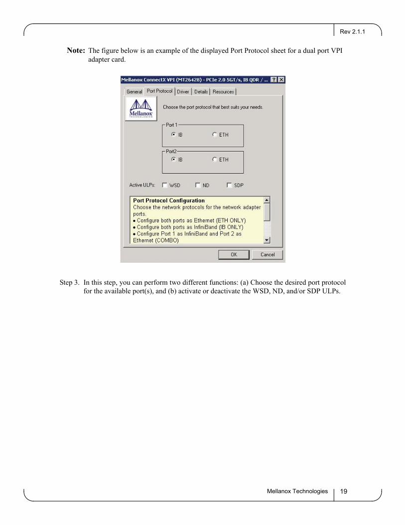
Note: The figure below is an example of the displayed Port Protocol sheet for a dual port VPI adapter card.
Step 3. In this step, you can perform two different functions: (a) Choose the desired port protocol for the available port(s), and (b) activate or deactivate the WSD, ND, and/or SDP ULPs.
Advanced Configuration for InfiniBand DriverRev 2.1.1
Mellanox Technologies20
8 Advanced Configuration for InfiniBand Driver
8.1 WDS Installation
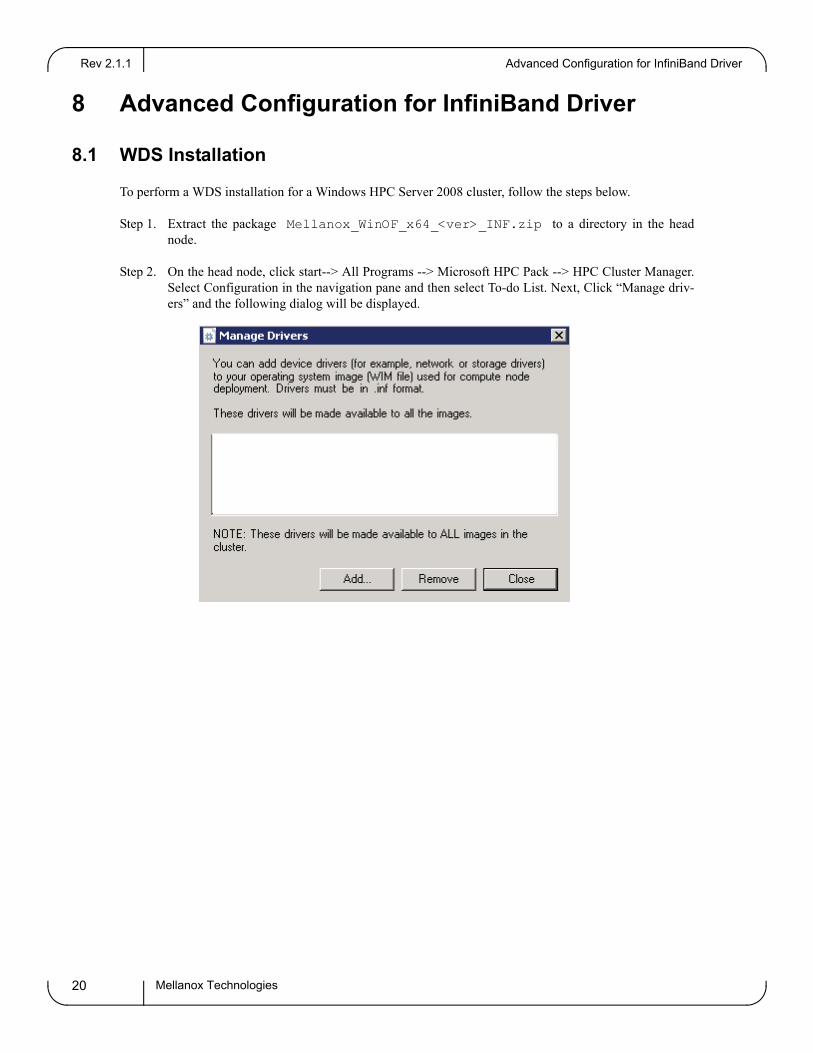
To perform a WDS installation for a Windows HPC Server 2008 cluster, follow the steps below.
Step 1. Extract the package Mellanox_WinOF_x64_<ver>_INF.zip to a directory in the head node.
Step 2. On the head node, click start--> All Programs --> Microsoft HPC Pack --> HPC Cluster Manager. Select Configuration in the navigation pane and then select To-do List. Next, Click “Manage driv-ers” and the following dialog will be displayed.
Rev 2.1.1
Mellanox Technologies 21
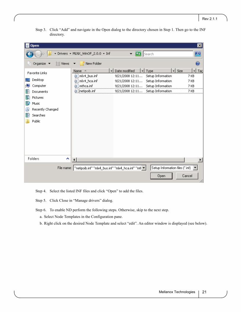
Step 3. Click “Add” and navigate in the Open dialog to the directory chosen in Step 1. Then go to the INF directory.
Step 4. Select the listed INF files and click “Open” to add the files.
Step 5. Click Close in “Manage drivers” dialog.
Step 6. To enable ND perform the following steps. Otherwise, skip to the next step.
a. Select Node Templates in the Configuration pane.
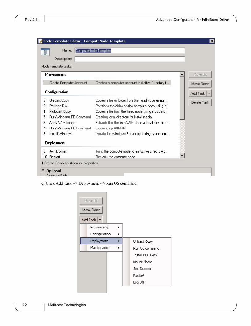
b. Right click on the desired Node Template and select “edit”. An editor window is displayed (see below).
Advanced Configuration for InfiniBand DriverRev 2.1.1
Mellanox Technologies22
c. Click Add Task --> Deployment --> Run OS command.
Rev 2.1.1
Mellanox Technologies 23
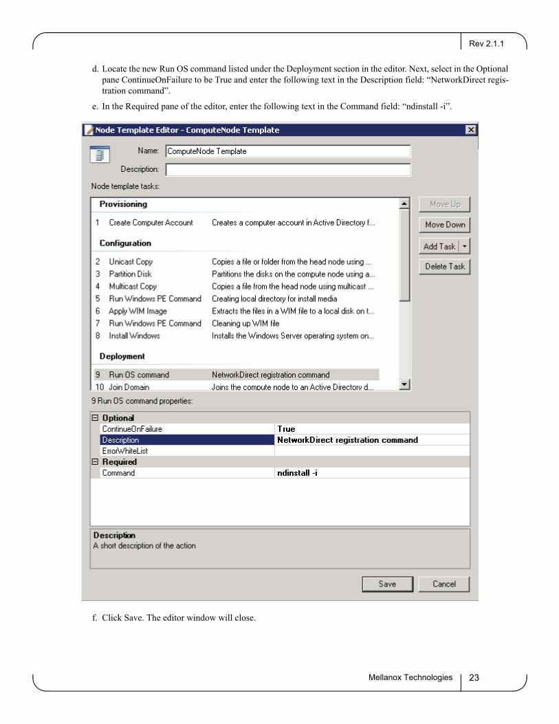
d. Locate the new Run OS command listed under the Deployment section in the editor. Next, select in the Optional pane ContinueOnFailure to be True and enter the following text in the Description field: “NetworkDirect regis-tration command”.
e. In the Required pane of the editor, enter the following text in the Command field: “ndinstall -i”.
f. Click Save. The editor window will close.
Advanced Configuration for InfiniBand DriverRev 2.1.1
Mellanox Technologies24
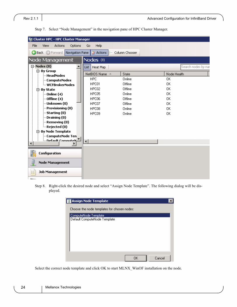
Step 7. Select “Node Management” in the navigation pane of HPC Cluster Manager.
Step 8. Right-click the desired node and select “Assign Node Template”. The following dialog will be dis-played.
Select the correct node template and click OK to start MLNX_WinOF installation on the node.
Rev 2.1.1
Mellanox Technologies 25
8.2 Modifying Configuration After Installation
8.2.1 Modifying Mellanox HCA Configuration
To modify HCA configuration after installation, perform the following steps:
a. Open the Registry editor by clicking Start->Run and entering ‘regedit’.
b. In the navigation pane, expand HKEY_LOCAL_MACHINE->SYSTEM->CurrentControlSet->Services.
c. Expand (in the navigation pane) the HCA driver service entry:
- ‘mtcha’ for the InfiniHost family- ‘mlx4_hca’ and ‘mlx4_bus’ for the ConnectX family
d. Click the Parameters entry in the expanded driver service entry to display HCA parameters.
e. Double click the desired HCA parameter and modify it. Repeat this step for all the parameters you wish to mod-ify.
f. Close the Registry editor after completing all modifications.
g. Open Device Manager and expand the correct InfiniBand Channel Adapters entry (i.e., the adapter with modi-fied parameters).
h. Right click the expanded HCA entry and left-click Disable. This disables the device.
i. Right click the expanded HCA entry and left-click Enable. This re-enables the device.
Note: For the changes to take effect, you must disable and re-enable the HCA (steps h and i above).
8.2.2 Modifying IPoIB Configuration
To modify the IPoIB configuration after installation, perform the following steps:
a. Open Device Manager and expand Network Adapters in the device display pane.
b. Right-click the Mellanox IPoIB Adapter entry and left-click Properties.
c. Click the Advanced tab and modify the desired properties.
Note: The IPoIB network interface is automatically restarted once you finish modifying IPoIB parameters.
You need to restart opensm after modifying IPoIB configuration.
Advanced Configuration for Ethernet DriverRev 2.1.1
Mellanox Technologies26
9 Advanced Configuration for Ethernet Driver
9.1 Displaying Adapter Related Information
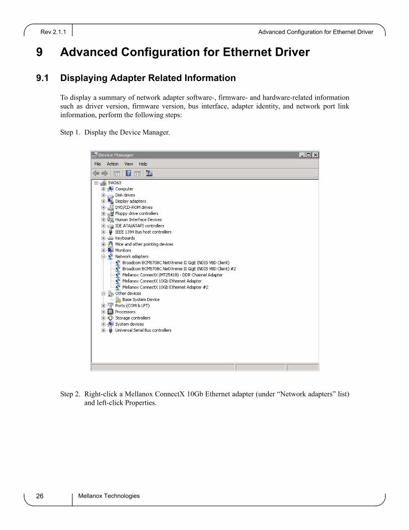
To display a summary of network adapter software-, firmware- and hardware-related information such as driver version, firmware version, bus interface, adapter identity, and network port link information, perform the following steps:
Step 1. Display the Device Manager.
Step 2. Right-click a Mellanox ConnectX 10Gb Ethernet adapter (under “Network adapters” list) and left-click Properties.
Rev 2.1.1
Mellanox Technologies 27
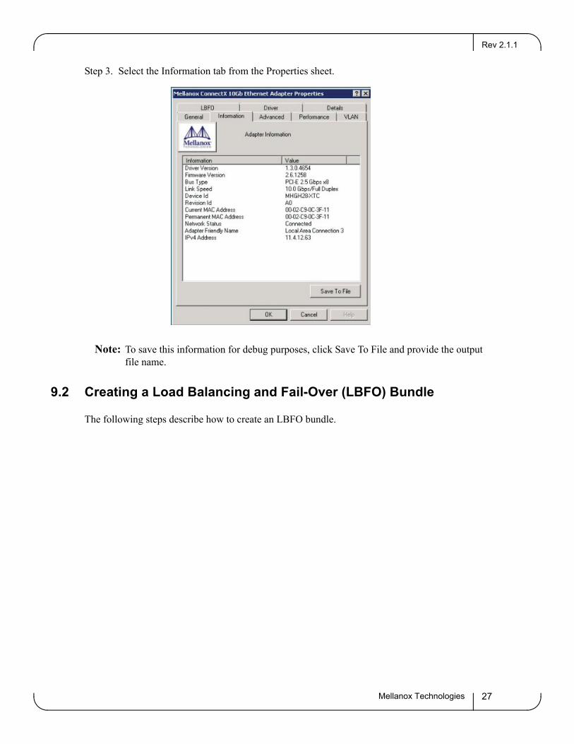
Step 3. Select the Information tab from the Properties sheet.
Note: To save this information for debug purposes, click Save To File and provide the output file name.
9.2 Creating a Load Balancing and Fail-Over (LBFO) Bundle
The following steps describe how to create an LBFO bundle.
Advanced Configuration for Ethernet DriverRev 2.1.1
Mellanox Technologies28
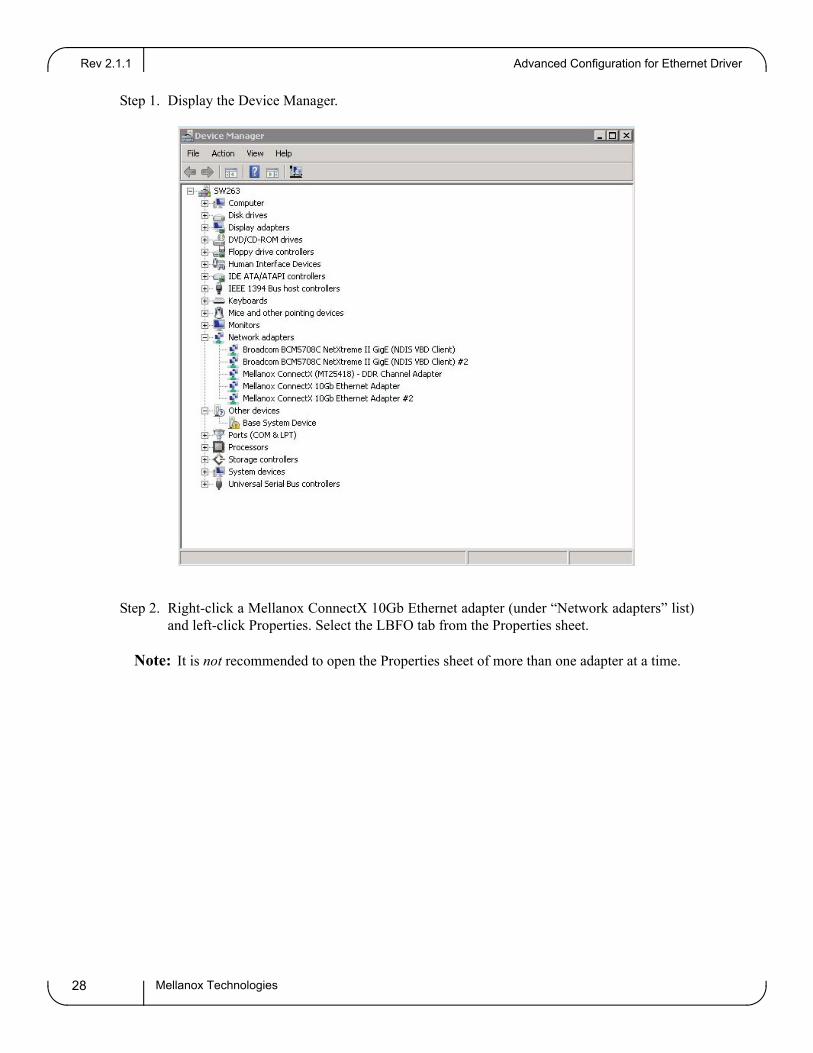
Step 1. Display the Device Manager.
Step 2. Right-click a Mellanox ConnectX 10Gb Ethernet adapter (under “Network adapters” list) and left-click Properties. Select the LBFO tab from the Properties sheet.
Note: It is not recommended to open the Properties sheet of more than one adapter at a time.
Rev 2.1.1
Mellanox Technologies 29
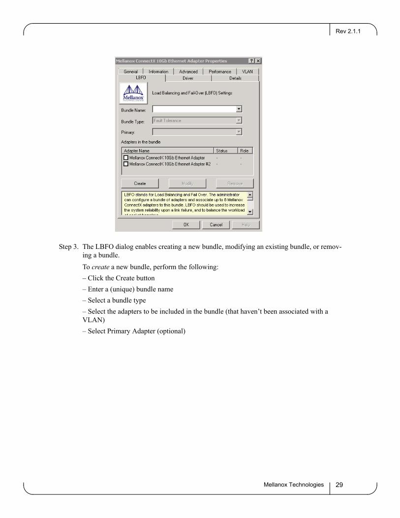
Step 3. The LBFO dialog enables creating a new bundle, modifying an existing bundle, or remov-ing a bundle.To create a new bundle, perform the following:– Click the Create button– Enter a (unique) bundle name– Select a bundle type– Select the adapters to be included in the bundle (that haven’t been associated with a VLAN)– Select Primary Adapter (optional)
Advanced Configuration for Ethernet DriverRev 2.1.1
Mellanox Technologies30
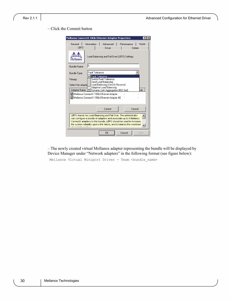
– Click the Commit button
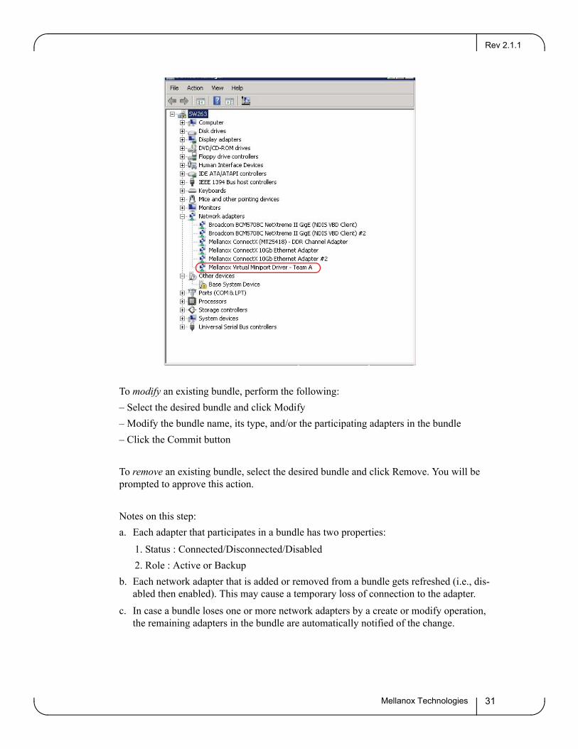
– The newly created virtual Mellanox adapter representing the bundle will be displayed by Device Manager under “Network adapters” in the following format (see figure below):
Mellanox Virtual Miniport Driver - Team <bundle_name>
Rev 2.1.1
Mellanox Technologies 31
To modify an existing bundle, perform the following:– Select the desired bundle and click Modify– Modify the bundle name, its type, and/or the participating adapters in the bundle– Click the Commit button
To remove an existing bundle, select the desired bundle and click Remove. You will be prompted to approve this action.
Notes on this step:a. Each adapter that participates in a bundle has two properties: 1. Status : Connected/Disconnected/Disabled 2. Role : Active or Backupb. Each network adapter that is added or removed from a bundle gets refreshed (i.e., dis-
abled then enabled). This may cause a temporary loss of connection to the adapter.c. In case a bundle loses one or more network adapters by a create or modify operation,
the remaining adapters in the bundle are automatically notified of the change.
Advanced Configuration for Ethernet DriverRev 2.1.1
Mellanox Technologies32
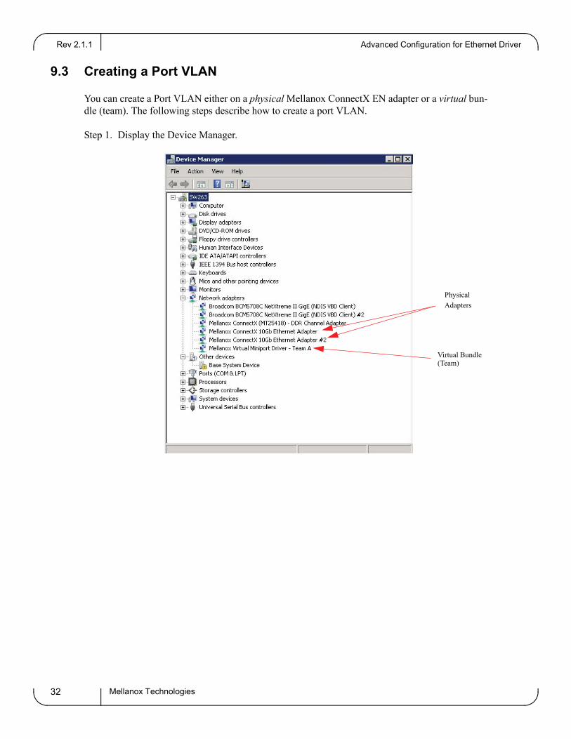
9.3 Creating a Port VLAN
You can create a Port VLAN either on a physical Mellanox ConnectX EN adapter or a virtual bun-dle (team). The following steps describe how to create a port VLAN.
Step 1. Display the Device Manager.
PhysicalAdapters
Virtual Bundle(Team)
Rev 2.1.1
Mellanox Technologies 33
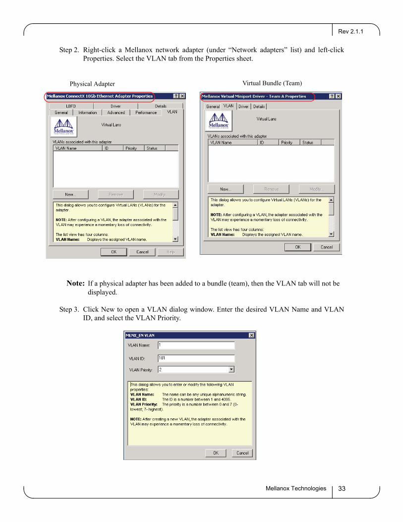
Step 2. Right-click a Mellanox network adapter (under “Network adapters” list) and left-click Properties. Select the VLAN tab from the Properties sheet.
Note: If a physical adapter has been added to a bundle (team), then the VLAN tab will not be displayed.
Step 3. Click New to open a VLAN dialog window. Enter the desired VLAN Name and VLAN ID, and select the VLAN Priority.
Physical Adapter Virtual Bundle (Team)
Advanced Configuration for Ethernet DriverRev 2.1.1
Mellanox Technologies34
Notes:a. After installing the first virtual adapter (VLAN) on a specific port, the port becomes
disabled. This means that it is not possible to bind to this port until all the virtual adapt-ers associated with it are removed.
b. After creating a new VLAN, make sure to set the IP address.c. When using VLAN, the network address is configured by means of the VLAN ID.
Therefore the VLAN ID on both ends of the connection must be the same.
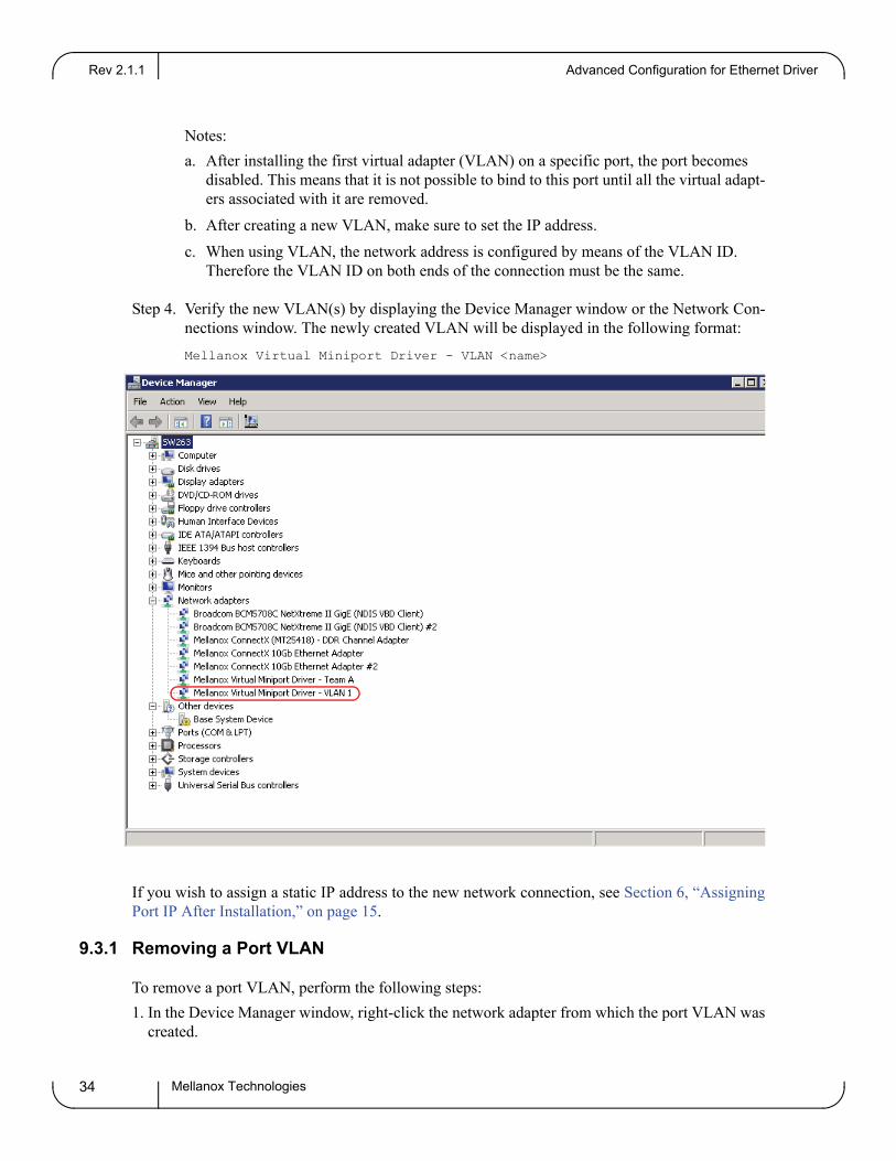
Step 4. Verify the new VLAN(s) by displaying the Device Manager window or the Network Con-nections window. The newly created VLAN will be displayed in the following format:Mellanox Virtual Miniport Driver - VLAN <name>
If you wish to assign a static IP address to the new network connection, see Section 6, “Assigning Port IP After Installation,” on page 15.
9.3.1 Removing a Port VLAN
To remove a port VLAN, perform the following steps:1. In the Device Manager window, right-click the network adapter from which the port VLAN was
created.
Rev 2.1.1
Mellanox Technologies 35
2. Left-click Properties.3. Select the VLAN tab from the Properties sheet.4. Select the VLAN to be removed.5. Click Remove and confirm the operation.
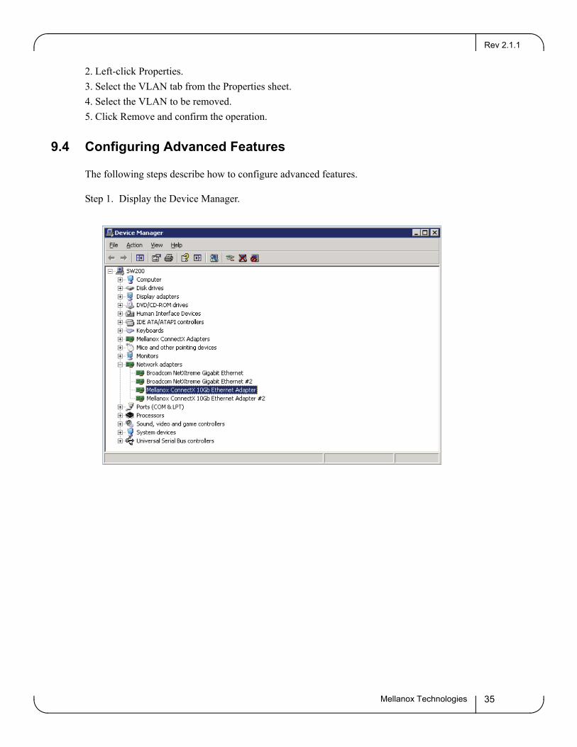
9.4 Configuring Advanced Features
The following steps describe how to configure advanced features.
Step 1. Display the Device Manager.
Advanced Configuration for Ethernet DriverRev 2.1.1
Mellanox Technologies36
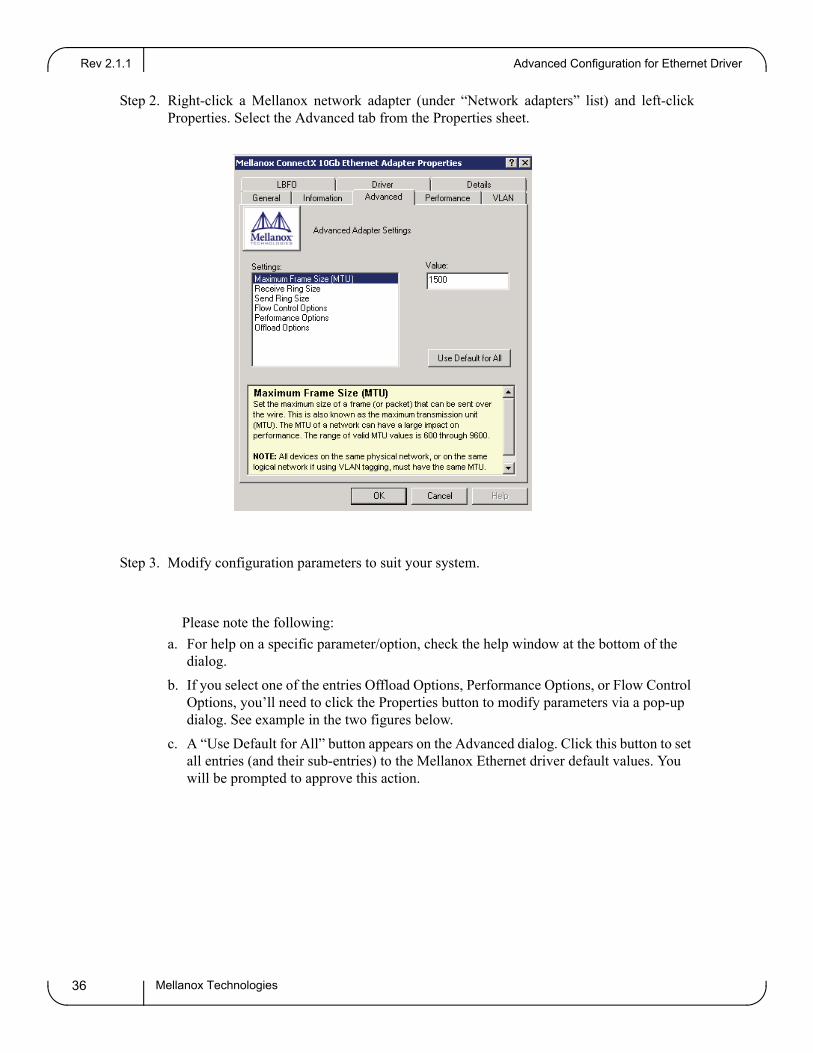
Step 2. Right-click a Mellanox network adapter (under “Network adapters” list) and left-click Properties. Select the Advanced tab from the Properties sheet.
Step 3. Modify configuration parameters to suit your system.
Please note the following:
a. For help on a specific parameter/option, check the help window at the bottom of the dialog.
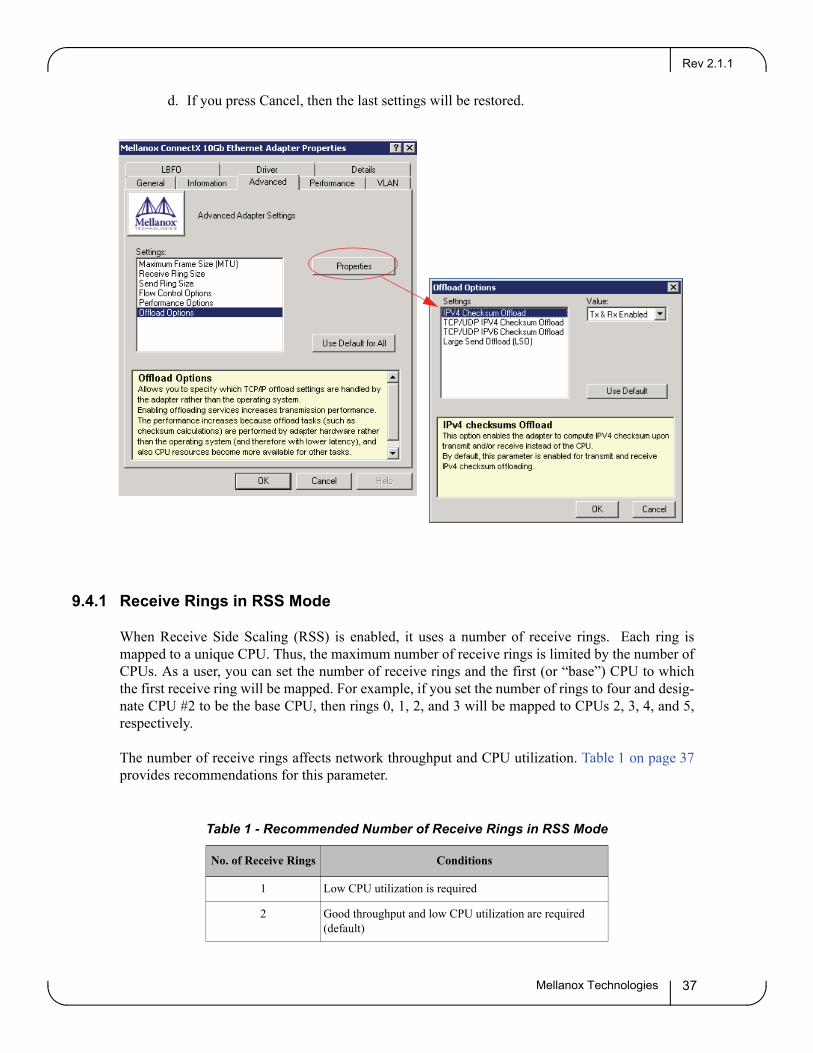
b. If you select one of the entries Offload Options, Performance Options, or Flow Control Options, you’ll need to click the Properties button to modify parameters via a pop-up dialog. See example in the two figures below.
c. A “Use Default for All” button appears on the Advanced dialog. Click this button to set all entries (and their sub-entries) to the Mellanox Ethernet driver default values. You will be prompted to approve this action.
Rev 2.1.1
Mellanox Technologies 37
d. If you press Cancel, then the last settings will be restored.
9.4.1 Receive Rings in RSS Mode
When Receive Side Scaling (RSS) is enabled, it uses a number of receive rings. Each ring is mapped to a unique CPU. Thus, the maximum number of receive rings is limited by the number of CPUs. As a user, you can set the number of receive rings and the first (or “base”) CPU to which the first receive ring will be mapped. For example, if you set the number of rings to four and desig-nate CPU #2 to be the base CPU, then rings 0, 1, 2, and 3 will be mapped to CPUs 2, 3, 4, and 5, respectively.
The number of receive rings affects network throughput and CPU utilization. Table 1 on page 37provides recommendations for this parameter.
Table 1 - Recommended Number of Receive Rings in RSS Mode
No. of Receive Rings Conditions
1 Low CPU utilization is required
2 Good throughput and low CPU utilization are required (default)
Advanced Configuration for Ethernet DriverRev 2.1.1
Mellanox Technologies38
To set the number of receive rings and the base CPU, perform the following:a. Go to the following registry key:
On Windows Server 2003: HKEY_LOCAL_MACHINE\SYSTEM\CurrentControlSet\Services\Tcpip\ParametersOn Windows Server 2008: HKEY_LOCAL_MACHINE\SYSTEM\CurrentControlSet\Services\Ndis\Parameters
b. Modify the parameter MaxNumRssCpus according to the recommendations in the table above.c. Set the parameter RssBaseCpu.
Note: If one or both parameters do not exist, please create them – their type is “REG_DWORD”.
d. Reboot the machine for the changes to take effect.
Updating Firmware
The following steps describe how to burn new firmware downloaded from Mellanox Technolo-gies’ Web pages under http://www.mellanox.com --> Support --> Firmware Download.
Step 1. Install the firmware tools package, MFT for Windows (WinMFT), on your machine. You can download it from http://www.mellanox.com --> Downloads --> Management Tools. Please check also the documentation on the same Web page.
Step 2. Open a CMD console. (Click Start-->Run and enter ‘cmd’.)
Step 3. Start mst. > net start mst
Step 4. Identify your target device for firmware update.a. Get the list of device names on your machine. > mst status
Found 2 devices:
mt25448_pciconf0
mt25448_pci_cr0
b. Your Ethernet device is the one with the postfix “_pci_cr0”. In the example listed above, this will be mt25448_pci_cr0. Use the string “mtXXXXX” to identify the device type by checking the Web
4 or more Applications demand maximum throughput and maximum transactions per second
Table 1 - Recommended Number of Receive Rings in RSS Mode
No. of Receive Rings Conditions
Rev 2.1.1
Mellanox Technologies 39
page http://pci-ids.ucw.cz/read/PC/15b3. In the example above, mtXXXXX=mt25448, and the device is a ConnectX EN.
c. Query the existing device firmware by running the following:> flint -d mt25448_pci_cr0 q
Image type: ConnectX
FW Version: 2.6.000
Device ID: 25448
Chip Revision: A0
Description: Port1 Port2
MACs: 0002c90018a4 0002c90018a5
Board ID: n/a (MT_0930110004) !!! <---- PSID
VSD: n/a
PSID: MT_0930110004
d. Now go to the Mellanox firmware download page at: http://www.mellanox.com --> Support --> Firmware Download.
e. Go to the correct firmware download page according to the device type identified in step (b) above.
Step 6. Using the PSID (Board ID) obtained in Step 4(c), download the appropriate firmware binary image (*.bin.zip) and unzip it.
Note: Make sure that the currently burnt firmware on your device is older than what is pro-vided on the Web page.
Step 7. Burn the firmware image using the flint utility (part of your installed WinMFT).
Note: Make sure that you burn the correct binary image to your adapter card. Burning the wrong image may cause severe firmware corruption. Please review Step 4 and Step 6 above.
> flint -d mt25448_pci_cr0 -image <image>.bin burn
Note: You may need to run ‘unzip’ on the downloaded firmware image prior to the burn opera-tion.
Step 8. Reboot your machine after the firmware burning is completed.
Uninstalling MLNX_VPIRev 2.1.1
Mellanox Technologies40
10 Uninstalling MLNX_VPI
Attended Uninstall
To uninstall MLNX_VPI on a single node, perform one of the following options:a. On Windows Server 2003: Click Start->Control Panel-> Add Remove Programs->
MLNX_VPI-> Remove. On Windows Server 2008: Click Start->Control Panel-> Programs and Features-> MLNX_VPI-> Remove. (NOTE: This requires elevated administrator privileges – see Section 1.3.2, “Software Requirements,” on page 5 for details.)
b. Double click the MSI and follow the instructions of the install wizard.
Unattended Uninstall
To uninstall MLNX_VPI in unattended mode, open a CMD console and enter the following com-mand:
> msiexec.exe /x MLNX_VPI_<arch>_<version>.msi /qn /forcerestart
Note: The ‘/forcerestart’ parameter forces the machine to restart after uninstalling the MLNX_VPI MSI. This is recommended action for a complete uninstall procedure.
Note: For all command options, enter ‘msiexec.exe /?’.