Embed Size (px)
Citation preview

Part Number: 180952-1CDRevision: 4
MLX300HARDWARE INSTALLATION, SOFTWARE UPGRADE AND OPTIONS INSTRUCTIONS
Upon receipt of the product and prior to initial operation, read instructions thoroughly, and retain for future reference.
1 of 92
180952-1CD
MLX300 Hardware Installation, Software
Upgrade and OptionsCopyright © 2018, 2017 Yaskawa America, Inc.
Terms of Use and Copyright NoticeAll rights reserved. This manual is freely available as a service to Yaskawa customers to assist in the operation of Motoman robots, related equipment and software This manual is copyrighted property of Yaskawa and may not be sold or redistributed in any way. You are welcome to copy this document to your computer or mobile device for easy access but you may not copy the PDF files to another website, blog, cloud storage site or any other means of storing or distributing Online content.
Printed in the United States of America
First Printing, 2017
YASKAWA America, Inc.Motoman Robotics Division100 Automation WayMiamisburg, OH 45342Phone: 937-847-6200
www.motoman.com
ii 180952-1CD 2 of 92
180952-1CD
SafetySummary of Warning Information
MLX300 Hardware Installation, Software
Upgrade and OptionsSafety
Summary of Warning Information
This manual is provided to help users establish safe conditions for operating the equipment. Specific considerations and precautions are also described in the manual, but appear in the form of Dangers, Warnings, Cautions, and Notice.
It is important that users operate the equipment in accordance with this instruction manual and any additional information which may be provided by Yaskawa. Address any questions regarding the safe and proper operation of the equipment to Customer Support.
Notes for Safe Operation
Read this manual carefully before installation, operation, maintenance, or inspection of the manipulator.
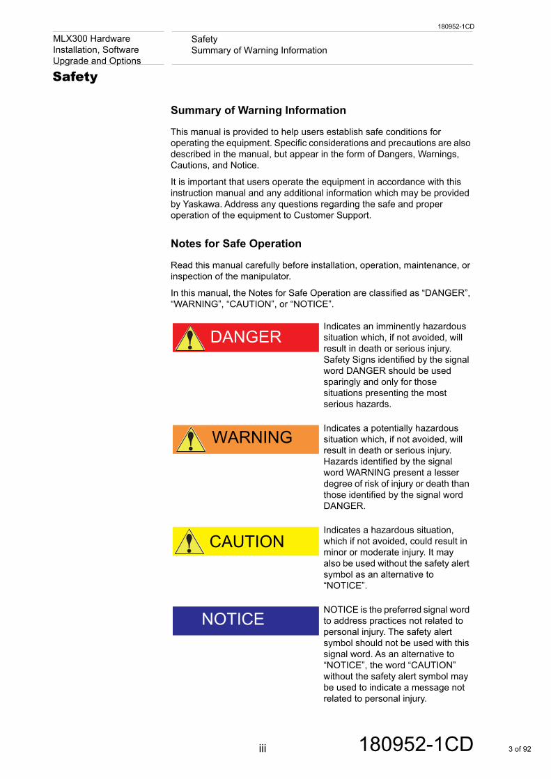
In this manual, the Notes for Safe Operation are classified as “DANGER”, “WARNING”, “CAUTION”, or “NOTICE”.
DANGERIndicates an imminently hazardous situation which, if not avoided, will result in death or serious injury. Safety Signs identified by the signal word DANGER should be used sparingly and only for those situations presenting the most serious hazards.
WARNINGIndicates a potentially hazardous situation which, if not avoided, will result in death or serious injury. Hazards identified by the signal word WARNING present a lesser degree of risk of injury or death than those identified by the signal word DANGER.
CAUTIONIndicates a hazardous situation, which if not avoided, could result in minor or moderate injury. It may also be used without the safety alert symbol as an alternative to “NOTICE”.
NOTICENOTICE is the preferred signal word to address practices not related to personal injury. The safety alert symbol should not be used with this signal word. As an alternative to “NOTICE”, the word “CAUTION” without the safety alert symbol may be used to indicate a message not related to personal injury.
iii 180952-1CD 3 of 92
180952-1CD
SafetyNotes for Safe Operation
MLX300 Hardware Installation, Software
Upgrade and OptionsItems described as “CAUTION” may result in a serious accident in some situations.
WARNING• This instruction manual is intended to explain the MLX300 software
and operating instructions. Make sure to read and understand this manual thoroughly before installing and operating the MLX300.
Failure to read and understand this manual may result is serious injury or death.
• Maintenance and inspection must be performed by specified personnel.
Failure to observe this Warning may result in electric shock or serious injury.
iv 180952-1CD 4 of 92
180952-1CD
SafetyNotes for Safe Operation
MLX300 Hardware Installation, Software
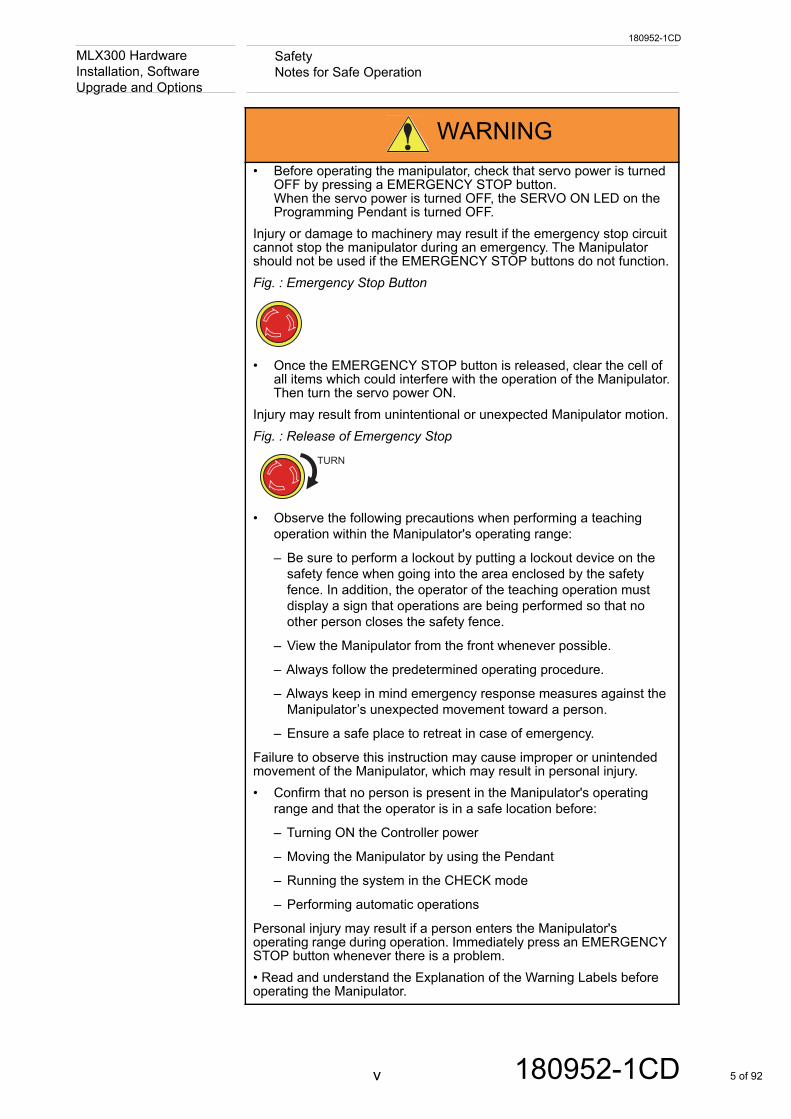
Upgrade and OptionsWARNING• Before operating the manipulator, check that servo power is turned
OFF by pressing a EMERGENCY STOP button.When the servo power is turned OFF, the SERVO ON LED on the Programming Pendant is turned OFF.
Injury or damage to machinery may result if the emergency stop circuit cannot stop the manipulator during an emergency. The Manipulator should not be used if the EMERGENCY STOP buttons do not function.Fig. : Emergency Stop Button
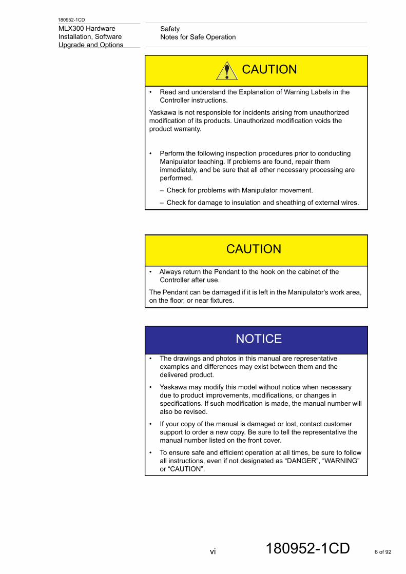
• Once the EMERGENCY STOP button is released, clear the cell of all items which could interfere with the operation of the Manipulator.Then turn the servo power ON.
Injury may result from unintentional or unexpected Manipulator motion.Fig. : Release of Emergency Stop
TURN
• Observe the following precautions when performing a teaching operation within the Manipulator's operating range:
– Be sure to perform a lockout by putting a lockout device on the safety fence when going into the area enclosed by the safety fence. In addition, the operator of the teaching operation must display a sign that operations are being performed so that no other person closes the safety fence.
– View the Manipulator from the front whenever possible.
– Always follow the predetermined operating procedure.
– Always keep in mind emergency response measures against the Manipulator’s unexpected movement toward a person.
– Ensure a safe place to retreat in case of emergency.
Failure to observe this instruction may cause improper or unintended movement of the Manipulator, which may result in personal injury.• Confirm that no person is present in the Manipulator's operating
range and that the operator is in a safe location before:
– Turning ON the Controller power
– Moving the Manipulator by using the Pendant
– Running the system in the CHECK mode
– Performing automatic operations
Personal injury may result if a person enters the Manipulator's operating range during operation. Immediately press an EMERGENCY STOP button whenever there is a problem. • Read and understand the Explanation of the Warning Labels before operating the Manipulator.
v 180952-1CD 5 of 92
180952-1CD
SafetyNotes for Safe Operation
MLX300 Hardware Installation, Software
Upgrade and OptionsCAUTION• Read and understand the Explanation of Warning Labels in the
Controller instructions.
Yaskawa is not responsible for incidents arising from unauthorized modification of its products. Unauthorized modification voids the product warranty.
• Perform the following inspection procedures prior to conducting Manipulator teaching. If problems are found, repair them immediately, and be sure that all other necessary processing are performed.
– Check for problems with Manipulator movement.
– Check for damage to insulation and sheathing of external wires.
CAUTION• Always return the Pendant to the hook on the cabinet of the
Controller after use.
The Pendant can be damaged if it is left in the Manipulator's work area, on the floor, or near fixtures.
NOTICE• The drawings and photos in this manual are representative
examples and differences may exist between them and the delivered product.
• Yaskawa may modify this model without notice when necessary due to product improvements, modifications, or changes in specifications. If such modification is made, the manual number will also be revised.
• If your copy of the manual is damaged or lost, contact customer support to order a new copy. Be sure to tell the representative the manual number listed on the front cover.
• To ensure safe and efficient operation at all times, be sure to follow all instructions, even if not designated as “DANGER”, “WARNING” or “CAUTION”.
vi 180952-1CD 6 of 92
180952-1CD
SafetyProgramming, Operation, and Maintenance Safety
MLX300 Hardware Installation, Software
Upgrade and OptionsProgramming, Operation, and Maintenance Safety
CAUTIONAll operators, programmers, maintenance personnel, supervisors, and anyone working near the system must become familiar with the operation of this equipment.
Improper operation can result in personal injury and/or damage to the equipment. Only trained personnel familiar with the operation, manuals, electrical design, and equipment interconnections of this equipment should be permitted to program, or maintain the system. All personnel involved with the operation of the equipment must understand potential dangers of operation.
• Inspect the equipment to be sure no potentially hazardous conditions exist. Be sure the area is clean and free of water, oil, debris, etc.
• Be sure that all safeguards are in place. Check all safety equipment for proper operation. Repair or replace any non-functioning safety equipment immediately.
• Check the EMERGENCY STOP button at the operator station for proper operation before programming. The equipment must be in EMEGENCY STOP (E-Stop) mode whenever it is not in use.
• Back up all programs and jobs onto suitable media before program changes are made. To avoid loss of information, programs, or jobs, a backup must always be made before any service procedures are done and before any changes are made to options, accessories, or equipment.
• Any modifications to the Controller unit can cause severe personal injury or death, as well as damage to the Manipulator. Do not make any modifications to the Controller unit. Making any changes without the written permission from Yaskawa will void the warranty.
• Some operations require standard passwords and some require special passwords.
• The equipment allows modifications to the software for maximum performance. Care must be taken when making modifications. All modifications made to the software will change the way the equipment operates and can cause severe personal injury or death, as well as damage parts of the system. Double check all modifications under every mode of operation to ensure that the changes have not created hazards or dangerous situations.
• This equipment has multiple sources of electrical supply. Electrical interconnections are made between the Controller and other equipment. Disconnect and lockout/tagout all electrical circuits before making any modifications or connections.
• Do not perform any maintenance procedures before reading and understanding the proper procedures in the appropriate manual.
• Use proper replacement parts.
Improper connections can damage equipment. All connections must be made within the standard voltage and current ratings of the equipment.
vii 180952-1CD 7 of 92
180952-1CD
SafetySafeguarding Tips
MLX300 Hardware Installation, Software
Upgrade and OptionsSafeguarding Tips
Mechanical Safety Devices
CAUTIONAll operators, programmers, maintenance personnel, supervisors, and anyone working near the system must become familiar with the operation of this equipment. All personnel involved with the operation of the equipment must understand potential dangers of operation. General safeguarding tips are as follows:
Improper operation can result in personal injury and/or damage to the equipment. Only trained personnel familiar with the operation of this equipment, the operator's manuals, the system equipment, and options and accessories should be permitted to operate this equipment.
• Improper connections can damage the equipment. All connections must be made within the standard voltage and current ratings of the equipment.
• The system must be placed in EMERGENCY STOP (E-Stop) mode whenever it is not in use.
• In accordance with ANSI/RIA R15.06-2012, section 4.2.5, Sources of Energy, use lockout/tagout procedures during equipment maintenance. Refer also to Section 1910.147 (29CFR, Part 1910), Occupational Safety and Health Standards for General Industry (OSHA).
CAUTIONThe safe operation of this equipment is ultimately the users responsibility. The conditions under which the equipment will be operated safely should be reviewed by the user. The user must be aware of the various national codes, ANSI/RIA R15.06-2012 safety standards, and other local codes that may pertain to the installation and use of this equipment.
Additional safety measures for personnel and equipment may be required depending on system installation, operation, and/or location. The following safety equipment is provided as standard:
Additional safety measures for personnel and equipment may be required depending on system installation, operation, and/or location. The following safety equipment is provided as standard:
• Safety barriers
• Door interlocks
• EMERGENCY STOP button located on the operator station
Check all safety equipment frequently for proper operation. Repair or replace any non-functioning safety equipment immediately.
viii 180952-1CD 8 of 92
180952-1CD
SafetyMaintenance Safety
MLX300 Hardware Installation, Software
Upgrade and OptionsMaintenance Safety
National Safety Standard
We suggest that you obtain and review a copy of the ANSI/RIA National Safety Standard for Industrial Robots and Robot Systems (ANSI/RIA R15.06-2012). You can obtain this document from the Robotic Industries Association (RIA) at the following address:
Robotic Industries Association900 Victors WayP.O. Box 3724
Ann Arbor, Michigan 48106TEL: (734) 994-6088FAX: (734) 994-3338
www.roboticsonline.com
Ultimately, well-trained personnel are the best safeguard against accidents and damage that can result from improper operation of the equipment. The customer is responsible for providing adequately trained personnel to operate, program, and maintain the equipment.
NEVER ALLOW UNTRAINED PERSONNEL TO OPERATE, PROGRAM, OR REPAIR THE EQUIPMENT!
We recommend approved Yaskawa training courses for all personnel involved with the operation, programming, or repair of the equipment.
This equipment has been tested and found to comply with the limits for a Class A digital device, pursuant to part 15 of the FCC rules. These limits are designed to provide reasonable protection against harmful interference when the equipment is operated in a commercial environment. This equipment generates, uses, and can radiate radio frequency energy and, if not installed and used in accordance with the instruction manual, may cause harmful interference to radio communications.
WARNING• Turn the power OFF, disconnect and lockout/tagout all electrical
circuits before making any modifications or connections.
Perform only the maintenance described in this manual. Maintenance other than specified in this manual should be performed only by Yaskawa-trained, qualified personnel.
ix 180952-1CD 9 of 92
180952-1CD
SafetyDefinition of Terms Used Often in This Manual
MLX300 Hardware Installation, Software
Upgrade and OptionsDefinition of Terms Used Often in This Manual
The MOTOMAN is a Yaskawa industrial robot product.
The MOTOMAN usually consists of the Manipulator, Controller, Programming Pendant, and supply cables.
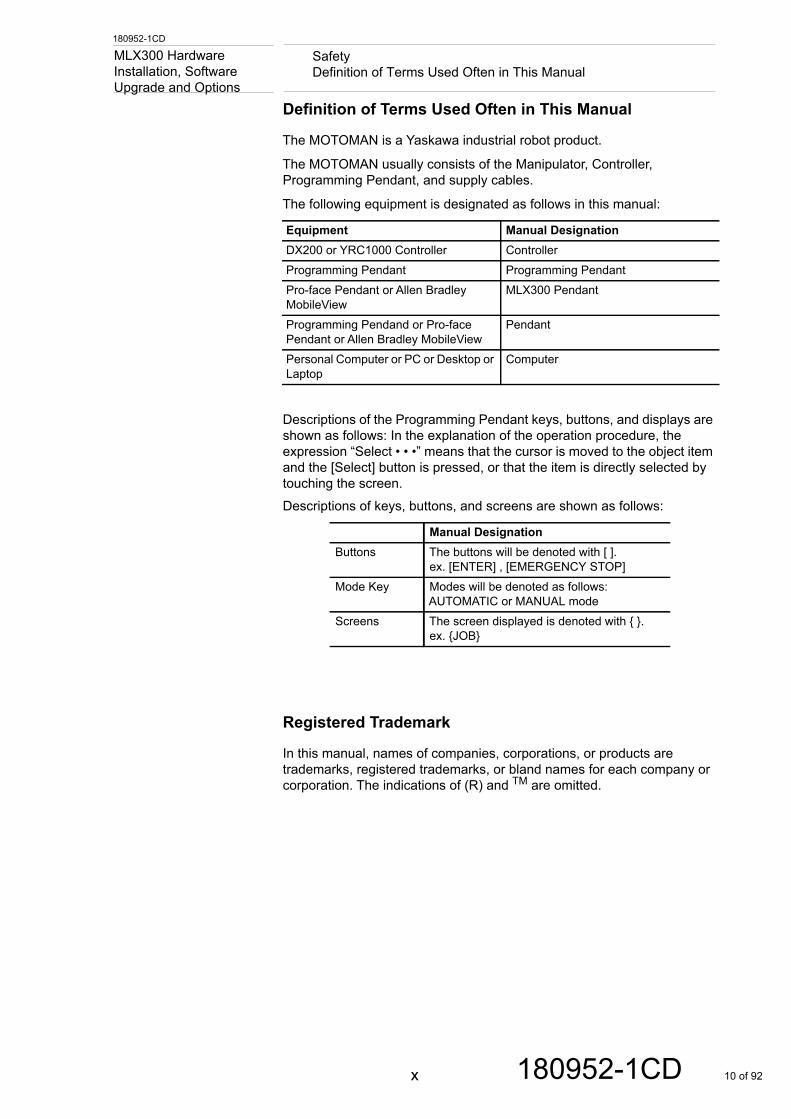
The following equipment is designated as follows in this manual:
Descriptions of the Programming Pendant keys, buttons, and displays are shown as follows: In the explanation of the operation procedure, the expression “Select • • •” means that the cursor is moved to the object item and the [Select] button is pressed, or that the item is directly selected by touching the screen.Descriptions of keys, buttons, and screens are shown as follows:
Registered Trademark
In this manual, names of companies, corporations, or products are trademarks, registered trademarks, or bland names for each company or corporation. The indications of (R) and TM are omitted.
Equipment Manual DesignationDX200 or YRC1000 Controller ControllerProgramming Pendant Programming PendantPro-face Pendant or Allen Bradley MobileView
MLX300 Pendant
Programming Pendand or Pro-face Pendant or Allen Bradley MobileView
Pendant
Personal Computer or PC or Desktop or Laptop
Computer
Manual DesignationButtons The buttons will be denoted with [ ].
ex. [ENTER] , [EMERGENCY STOP]Mode Key Modes will be denoted as follows:
AUTOMATIC or MANUAL modeScreens The screen displayed is denoted with { }.
ex. {JOB}
x 180952-1CD 10 of 92
180952-1CD
Customer Support InformationRegistered Trademark
MLX300 Hardware Installation, Software
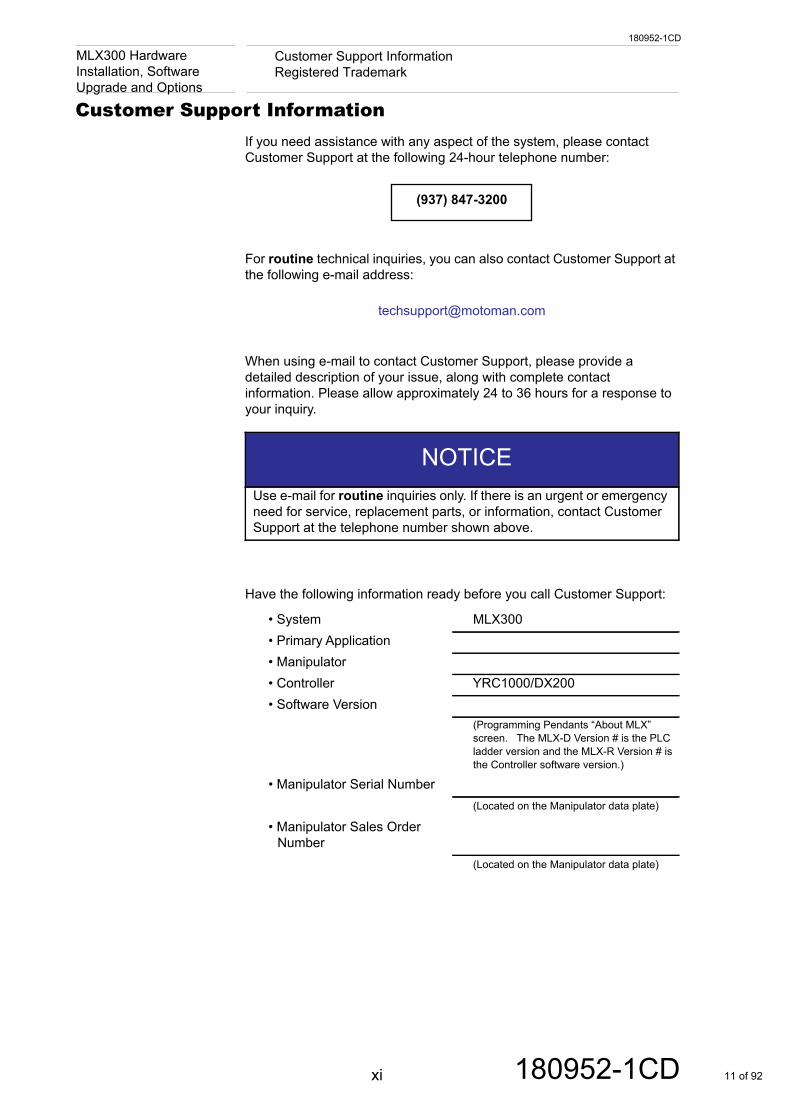
Upgrade and OptionsCustomer Support InformationIf you need assistance with any aspect of the system, please contact Customer Support at the following 24-hour telephone number:
For routine technical inquiries, you can also contact Customer Support at the following e-mail address:
When using e-mail to contact Customer Support, please provide a detailed description of your issue, along with complete contact information. Please allow approximately 24 to 36 hours for a response to your inquiry.
Have the following information ready before you call Customer Support:
NOTICEUse e-mail for routine inquiries only. If there is an urgent or emergency need for service, replacement parts, or information, contact Customer Support at the telephone number shown above.
• System MLX300• Primary Application• Manipulator• Controller YRC1000/DX200• Software Version
(Programming Pendants “About MLX” screen. The MLX-D Version # is the PLC ladder version and the MLX-R Version # is the Controller software version.)
• Manipulator Serial Number(Located on the Manipulator data plate)
• Manipulator Sales Order Number
(Located on the Manipulator data plate)
(937) 847-3200
xi 180952-1CD 11 of 92
180952-1CD
Table of ContentsMLX300 Hardware Installation, Software
Upgrade and OptionsTable of Contents
1 Introduction ..................................................................................................................................... 1-1
1.1 About This Document ........................................................................................................ 1-1
1.2 System Overview............................................................................................................... 1-2
1.3 Reference Documentation ................................................................................................. 1-3
1.4 Quick Start Guide .............................................................................................................. 1-4
2 MLX300 Hardware Installation........................................................................................................ 2-1
2.1 MLX300 Hardware Configurations..................................................................................... 2-1
2.2 MLX300 Pendant Options.................................................................................................. 2-7
2.3 MLX300 Hardware Options and Requirements ................................................................. 2-8
2.3.1 Minimum Requirements........................................................................................ 2-82.3.1.1 List of Optional PLC, Pendant, and HMI Hardware................................. 2-8
2.4 Pendant Interface Drawings .............................................................................................. 2-9
2.4.1 Installing a Pro-Face Pendant to the DX200 Controller........................................ 2-9
2.4.2 Installing a Pro-Face Pendant to the YRC1000 Controller ................................. 2-10
2.4.3 Installing a MobileView Pendant to the DX200 Controller .................................. 2-11
2.4.4 Adding a MobileView Pendant to the YRC1000 Controller ................................ 2-12
2.5 Pendant Bypass Plug Drawings ...................................................................................... 2-13
2.5.1 Pro-Face Bypass Plug........................................................................................ 2-13
2.5.2 MobileView Bypass Plug .................................................................................... 2-13
2.6 Enabling Device............................................................................................................... 2-14
2.6.1 Adding an Enabling Device to the DX200 Controller.......................................... 2-14
2.6.2 Adding an Enabling Device to the YRC1000 Controller ..................................... 2-15
2.7 External E-Stop and Safety Fence .................................................................................. 2-16
2.7.1 Adding External E-Stop and Safety Gate Wiring to DX200................................ 2-16
2.7.2 Adding External E-Stop and Safety Gate Wiring to YRC1000 ........................... 2-17
2.8 Controller Inputs and Outputs.......................................................................................... 2-18
2.8.1 DX200 Controller I/O .......................................................................................... 2-18
2.8.2 YRC1000 Controller I/O...................................................................................... 2-19
3 MLX300 Software ........................................................................................................................... 3-1
3.1 PLC Ladder Software ........................................................................................................ 3-1
xii 180952-1CD 12 of 92
180952-1CD
Table of ContentsMLX300 Hardware Installation, Software
Upgrade and Options3.2 Rockwell HMI and Pendant Software ................................................................................3-2
3.2.1 MobileView Settings .............................................................................................3-3
3.3 Pro-face HMI and Pendant Software .................................................................................3-4
4 Collision Detection Setup................................................................................................................4-1
4.1 Summary of Operations to Change Collision Detection.....................................................4-1
4.2 Login as Manager ..............................................................................................................4-2
4.3 Collision Detection Setting - AUTO Mode..........................................................................4-3
4.4 Collision Detection Setting - TEACH Mode........................................................................4-5
5 Soft Limits Adjustments...................................................................................................................5-1
6 Brake Release.................................................................................................................................6-1
7 Shipping Position ............................................................................................................................7-1
8 MLX300 PLC Software Version Upgrade Procedure ......................................................................8-1
8.1 Export Manipulator Application Data from RSLogix Ladder...............................................8-1
8.2 Export non-MLX Tasks from the RSLogix Ladder .............................................................8-2
8.3 Download New Version of MLX300 PLC Software ............................................................8-2
8.4 Setup I/O Configuration in RSLogix Ladder.......................................................................8-2
8.5 Import Tasks into the New RSLogix Ladder ......................................................................8-2
8.6 Import the Manipulator Application Data into the PLC Ladder...........................................8-3
9 Motosim EG-VRC Virtual Controller Setup Procedure....................................................................9-1
9.1 Pre-requisites.....................................................................................................................9-1
9.2 Debug Mode for Simulation ...............................................................................................9-1
9.3 Create a MotoSim EG-VRC Project...................................................................................9-2
9.4 Starting Online Function ....................................................................................................9-6
9.5 Option to use Motosim with the Manipulator Disconnected ...............................................9-7
Appendix A ....................................................................................................................................... A-1
A.1 Method to Disconnect Programming Pendant with Software ........................................... A-1
A.2 Method to Reconnect Programming Pendant with Software............................................ A-2
Appendix B ....................................................................................................................................... B-1
B.1 Glossary ........................................................................................................................... B-1
xiii 180952-1CD 13 of 92
180952-1CD
1 Introduction1.1 About This Document
MLX300 Hardware Installation, Software
Upgrade and Options1 Introduction
1.1 About This Document
This manual provides the following information:
Chapter 1 “Introduction”Provides general information about the Manual, Software and its components.
Chapter 2 “MLX300 Hardware Installation”This chapter provides Hardware installation procedures.
Chapter 3 “MLX300 Software”This chapter provides information concerning the software.
Chapter 4 “Collision Detection Setup”Provides information concerning Collision Detection including how to set it up.
Chapter 5 “Soft Limits Adjustments”This chapter provides information for adjusting the Soft Limits.
Chapter 6 “Brake Release”This chapter provides information on how to release the brakes.
Chapter 7 “Shipping Position”This chapter provides information on how to ship the Manipulator.
Chapter 8 “MLX300 PLC Software Version Upgrade Procedure”This chapter provides information on upgrading software
Chapter 9 “Motosim EG-VRC Virtual Controller Setup Procedure”This chapter provides information on how to set up the Motosim EG-VRC software.
Appendix AThis appendix provides information on how to connect and disconnect Programming Pendant with software.
Appendix BThis appendix contains a list and terms that may be needed to know with this system.
1-1 180952-1CD 14 of 92
180952-1CD
1 Introduction1.2 System Overview
MLX300 Hardware Installation, Software
Upgrade and Options1.2 System Overview
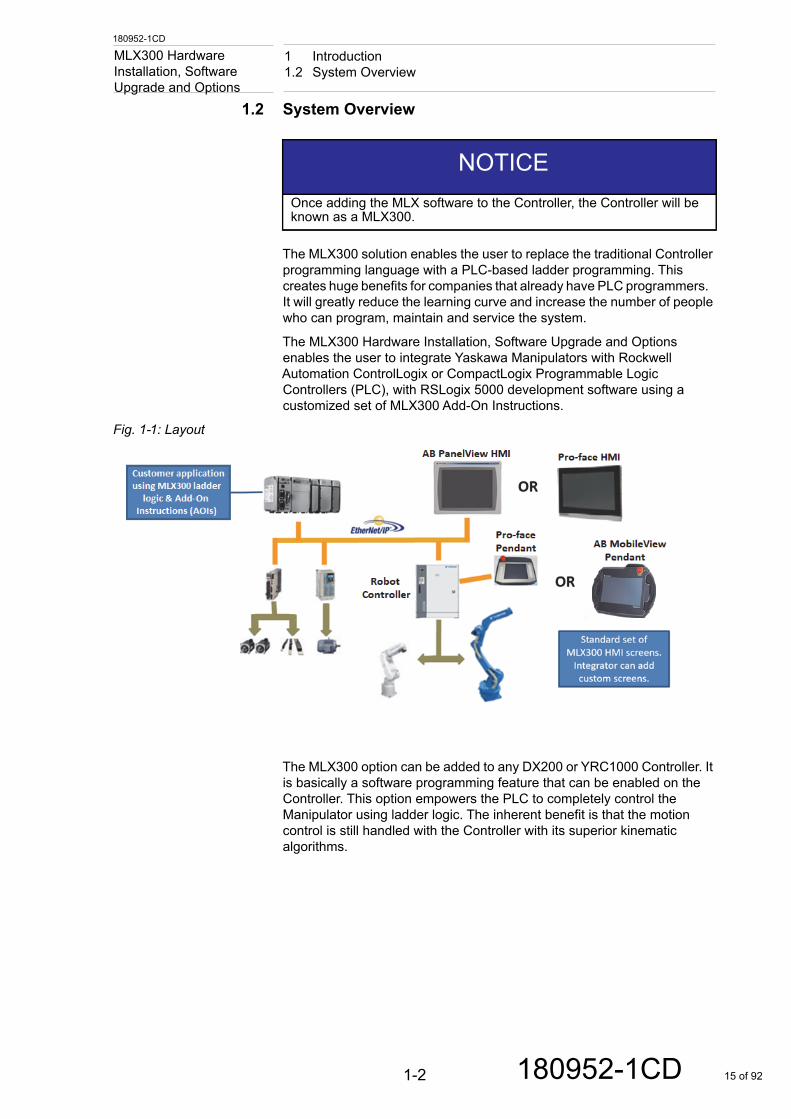
The MLX300 solution enables the user to replace the traditional Controller programming language with a PLC-based ladder programming. This creates huge benefits for companies that already have PLC programmers. It will greatly reduce the learning curve and increase the number of people who can program, maintain and service the system.
The MLX300 Hardware Installation, Software Upgrade and Options enables the user to integrate Yaskawa Manipulators with Rockwell Automation ControlLogix or CompactLogix Programmable Logic Controllers (PLC), with RSLogix 5000 development software using a customized set of MLX300 Add-On Instructions.
Fig. 1-1: Layout
The MLX300 option can be added to any DX200 or YRC1000 Controller. It is basically a software programming feature that can be enabled on the Controller. This option empowers the PLC to completely control the Manipulator using ladder logic. The inherent benefit is that the motion control is still handled with the Controller with its superior kinematic algorithms.
NOTICEOnce adding the MLX software to the Controller, the Controller will be known as a MLX300.
1-2 180952-1CD 15 of 92
180952-1CD
1 Introduction1.3 Reference Documentation
MLX300 Hardware Installation, Software
Upgrade and Options1.3 Reference Documentation
For additional information on individual components of the Software, refer to the following documentation that is included with the system:
• Yaskawa Motoman Manipulator Manual –Varies by Manipulator Supplied
• Yaskawa Motoman Controller Instruction Manual\–YRC1000 (179531-1CD)–DX200 (165292-1CD)
• Yaskawa Controller Maintenance Manual–YRC1000 (178643-1CD)–DX200 (165293-1CD)
• Yaskawa Operator's Manual for the application–Varies by Controller and application
• Yaskawa Controller Concurrent I/O Manual –YRC1000 (178648-1CD)–DX200 (165294-1CD)
• Yaskawa Controller INFORM User’s Manual–YRC1000 (178649-1CD)–DX200 (165301-1CD)
• Yaskawa MotoSim EG-VRC Operators Manual (156225-1CD)
• Yaskawa MLX300 Application Backup Manual (181925-1CD)
• Yaskawa MLX300 Software and Operating User’s Manual (180247-1CD)
• Vendor manuals for system components not manufactured by Yaskawa
1-3 180952-1CD 16 of 92
1 Introduction1.4 Quick Start Guide
1-4
180952-1CDMLX300 Hardware Installation, Software Upgrade and Options
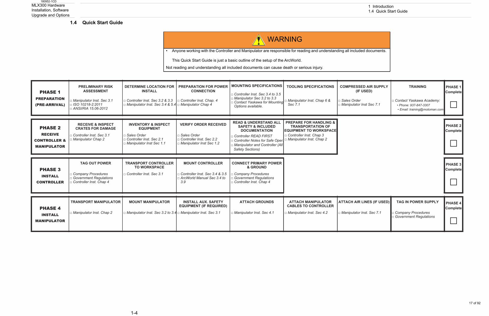
1.4 Quick Start Guide
WARNING• Anyone working with the Controller and Manipulator are responsible for reading and understanding all included documents.
This Quick Start Guide is just a basic outline of the setup of the ArcWorld.
Not reading and understanding all included documents can cause death or serious injury.
PHASE 1PREPARATION (PRE-ARRIVAL)
PRELIMINARY RISK ASSESSMENT
DETERMINE LOCATION FOR INSTALL
PREPARATION FOR POWER CONNECTION
MOUNTING SPECIFICATIONS □ Controller Inst. Sec 3.4 to 3.5 □ Manipulator Sec 3.2 to 3.3 □ Contact Yaskawa for Mounting
Options available.
TOOLING SPECIFICATIONS COMPRESSED AIR SUPPLY(IF USED)
TRAINING PHASE 1Complete
□ □ Manipulator Inst. Sec 3.1 □ ISO 10218-2:2011 □ ANSI/RIA 15.06-2012
□ Controller Inst. Sec 3.2 & 3.3 □ Manipulator Inst. Sec 3.4 & 5.4
□ Controller Inst. Chap. 4 □ Manipulator Chap 4
□ Manipulator Inst. Chap 6 & Sec 7.1
□ Sales Order □ Manipulator Inst Sec 7.1
□ Contact Yaskawa Academy: • Phone: 937-847-3307 • Email: [email protected]
PHASE 2RECEIVE
CONTROLLER & MANIPULATOR
RECEIVE & INSPECT CRATES FOR DAMAGE
INVENTORY & INSPECT EQUIPMENT
VERIFY ORDER RECEIVED READ & UNDERSTAND ALL SAFETY & INCLUDED
DOCUMENTATION
PREPARE FOR HANDLING & TRANSPORTATION OF
EQUIPMENT TO WORKSPACEPHASE 2Complete
□ □ Controller Inst. Sec 3.1 □ Manipulator Chap 2
□ Sales Order □ Controller Inst. Sec 2.1 □ Manipulator Inst Sec 1.1
□ Sales Order □ Controller Inst. Sec 2.2 □ Manipulator Inst Sec 1.2
□ Controller READ FIRST □ Controller Notes for Safe Oper. □ Manipulator and Controller (All
Safety Sections)
□ Controller Inst. Chap 3 □ Manipulator Inst. Chap 2
PHASE 3INSTALL
CONTROLLER
TAG OUT POWER TRANSPORT CONTROLLER TO WORKSPACE
MOUNT CONTROLLER CONNECT PRIMARY POWER& GROUND
PHASE 3Complete
□ □ Company Procedures □ Government Regulations □ Controller Inst. Chap 4
□ Controller Inst. Sec 3.1
□ Controller Inst. Sec 3.4 & 3.5 □ ArcWorld Manual Sec 3.4 to
3.9
□ Company Procedures □ Government Regulations □ Controller Inst. Chap 4
PHASE 4INSTALL
MANIPULATOR
TRANSPORT MANIPULATOR MOUNT MANIPULATOR INSTALL AUX. SAFETY EQUIPMENT (IF REQUIRED)
ATTACH GROUNDS ATTACH MANIPULATOR CABLES TO CONTROLLER
ATTACH AIR LINES (IF USED) TAG IN POWER SUPPLY PHASE 4Complete
□ □ Manipulator Inst. Chap 2 □ Manipulator Inst. Sec 3.2 to 3.4
□ Manipulator Inst. Sec 3.1
□ Manipulator Inst. Sec 4.1 □ Manipulator Inst. Sec 4.2 □ Manipulator Inst. Sec 7.1 □ Company Procedures □ Government Regulations
17 of 92
180952-1CD
2 MLX300 Hardware Installation2.1 MLX300 Hardware Configurations
MLX300 Hardware Installation, Software
Upgrade and Options2 MLX300 Hardware Installation
2.1 MLX300 Hardware Configurations
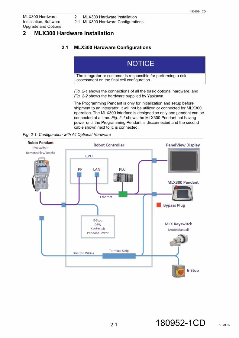
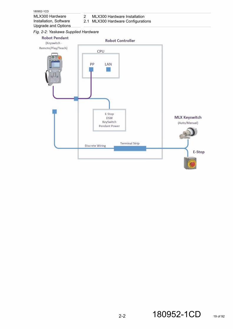
Fig. 2-1 shows the connections of all the basic optional hardware, and Fig. 2-2 shows the hardware supplied by Yaskawa.
The Programming Pendant is only for initialization and setup before shipment to an integrator. It will not be utilized or connected for MLX300 operation. The MLX300 interface is designed so only one pendant can be connected at a time. Fig. 2-1 shows the MLX300 Pendant not having power until the Programming Pendant is disconnected and the second cable shown next to it, is connected.
Fig. 2-1: Configuration with All Optional Hardware
NOTICEThe integrator or customer is responsible for performing a risk assessment on the final cell configuration.
2-1 180952-1CD 18 of 92
180952-1CD
2 MLX300 Hardware Installation2.1 MLX300 Hardware Configurations
MLX300 Hardware Installation, Software
Upgrade and OptionsFig. 2-2: Yaskawa Supplied Hardware2-2 180952-1CD 19 of 92
180952-1CD
2 MLX300 Hardware Installation2.1 MLX300 Hardware Configurations
MLX300 Hardware Installation, Software
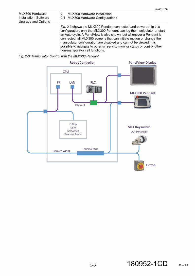
Upgrade and OptionsFig. 2-3 shows the MLX300 Pendant connected and powered. In this configuration, only the MLX300 Pendant can jog the manipulator or start an Auto cycle. A PanelView is also shown, but whenever a Pendant is connected, all MLX300 screens that can initiate motion or change the manipulator configuration are disabled and cannot be viewed. It is possible to navigate to other screens to monitor status or control other non-manipulator cell functions.
Fig. 2-3: Manipulator Control with the MLX300 Pendant
2-3 180952-1CD 20 of 92
180952-1CD
2 MLX300 Hardware Installation2.1 MLX300 Hardware Configurations
MLX300 Hardware Installation, Software
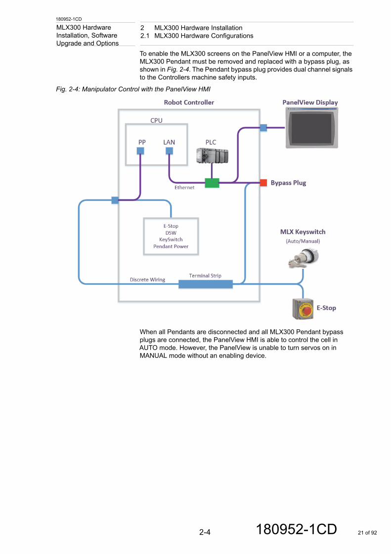
Upgrade and OptionsTo enable the MLX300 screens on the PanelView HMI or a computer, the MLX300 Pendant must be removed and replaced with a bypass plug, as shown in Fig. 2-4. The Pendant bypass plug provides dual channel signals to the Controllers machine safety inputs.
Fig. 2-4: Manipulator Control with the PanelView HMI
When all Pendants are disconnected and all MLX300 Pendant bypass plugs are connected, the PanelView HMI is able to control the cell in AUTO mode. However, the PanelView is unable to turn servos on in MANUAL mode without an enabling device.
2-4 180952-1CD 21 of 92
180952-1CD
2 MLX300 Hardware Installation2.1 MLX300 Hardware Configurations
MLX300 Hardware Installation, Software
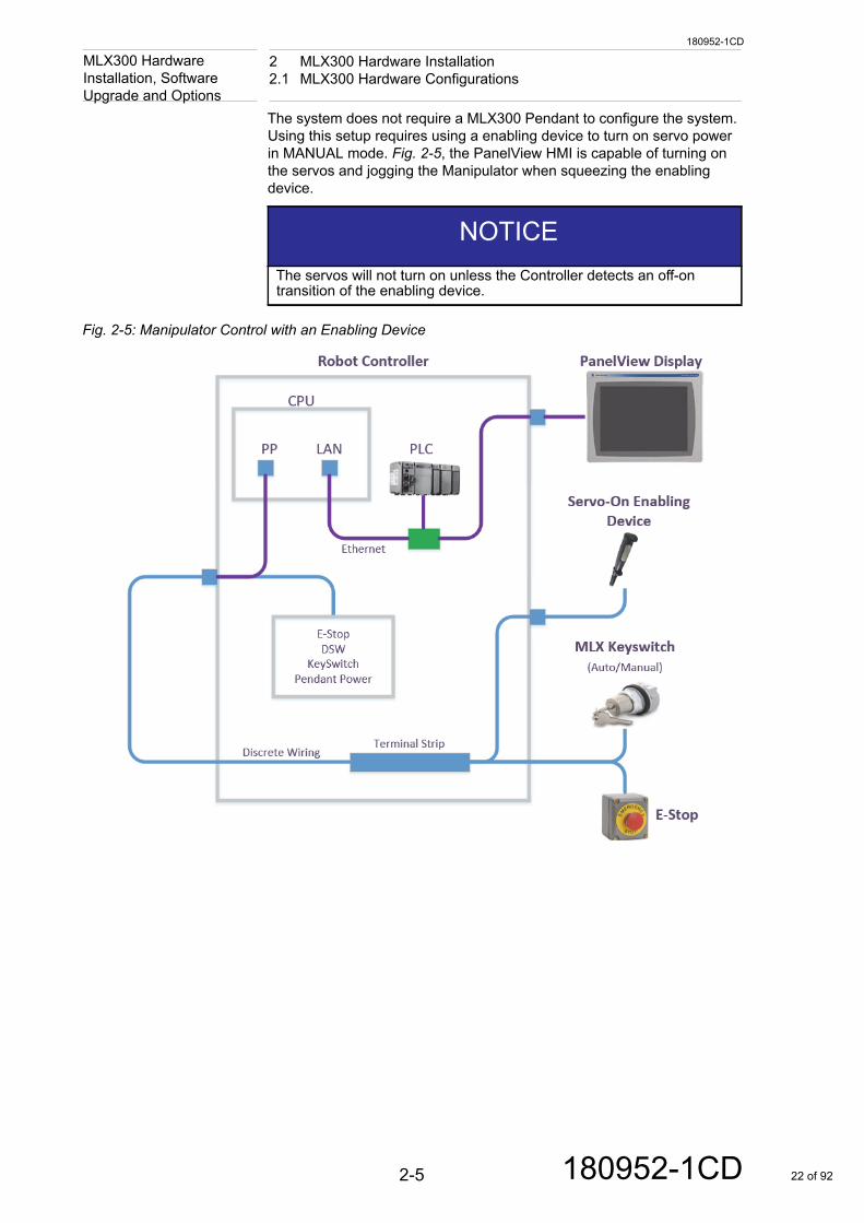
Upgrade and OptionsThe system does not require a MLX300 Pendant to configure the system. Using this setup requires using a enabling device to turn on servo power in MANUAL mode. Fig. 2-5, the PanelView HMI is capable of turning on the servos and jogging the Manipulator when squeezing the enabling device.
Fig. 2-5: Manipulator Control with an Enabling Device
NOTICEThe servos will not turn on unless the Controller detects an off-on transition of the enabling device.
2-5 180952-1CD 22 of 92
180952-1CD
2 MLX300 Hardware Installation2.1 MLX300 Hardware Configurations
MLX300 Hardware Installation, Software
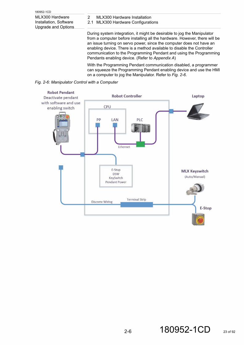
Upgrade and OptionsDuring system integration, it might be desirable to jog the Manipulator from a computer before installing all the hardware. However, there will be an issue turning on servo power, since the computer does not have an enabling device. There is a method available to disable the Controller communication to the Programming Pendant and using the Programming Pendants enabling device. (Refer to Appendix A)With the Programming Pendant communication disabled, a programmer can squeeze the Programming Pendant enabling device and use the HMI on a computer to jog the Manipulator. Refer to Fig. 2-6.
Fig. 2-6: Manipulator Control with a Computer
2-6 180952-1CD 23 of 92
180952-1CD
2 MLX300 Hardware Installation2.2 MLX300 Pendant Options
MLX300 Hardware Installation, Software
Upgrade and Options2.2 MLX300 Pendant Options
For a typical MLX300 system, there are two teach pendants. The Programming Pendant comes with the MLX300 package. This Pendant is primarily for the initial Controller initialization and setup, which is done by Yaskawa before shipment. The Programming Pendant is disconnected for MLX300 operations.
A MLX300 Pendant can be added by the integrator for MLX300 HMI operations, which includes a Manipulator program control, jogging, and teaching points.
Yaskawa provides software HMI screens for two choices; the Pro-face Pendant and the Allen Bradley MobileView Pendant. This software platform is designed to provide a seamless transition from the previous generation of MLX Controllers. Technical tutorials on how to use the MLX HMI are available on the Motoman website.
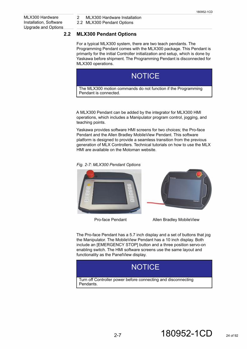
Fig. 2-7: MLX300 Pendant Options
The Pro-face Pendant has a 5.7 inch display and a set of buttons that jog the Manipulator. The MobileView Pendant has a 10 inch display. Both include an [EMERGENCY STOP] button and a three position servo-on enabling switch. The HMI software screens use the same layout and functionality as the PanelView display.
NOTICEThe MLX300 motion commands do not function if the Programming Pendant is connected.
NOTICETurn off Controller power before connecting and disconnecting Pendants.
Pro-face Pendant Allen Bradley MobileView
2-7 180952-1CD 24 of 92
180952-1CD
2 MLX300 Hardware Installation2.3 MLX300 Hardware Options and Requirements
MLX300 Hardware Installation, Software
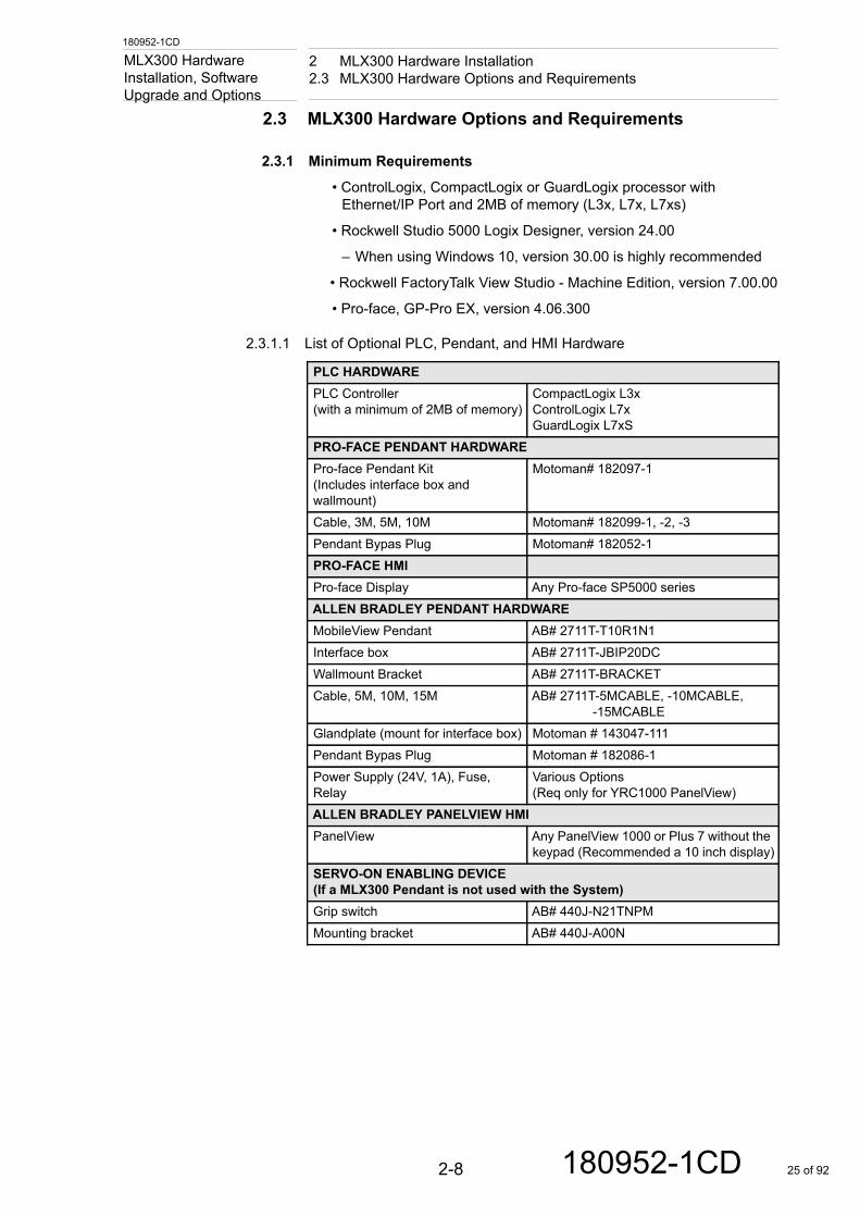
Upgrade and Options2.3 MLX300 Hardware Options and Requirements
2.3.1 Minimum Requirements
• ControlLogix, CompactLogix or GuardLogix processor with Ethernet/IP Port and 2MB of memory (L3x, L7x, L7xs)
• Rockwell Studio 5000 Logix Designer, version 24.00
– When using Windows 10, version 30.00 is highly recommended
• Rockwell FactoryTalk View Studio - Machine Edition, version 7.00.00
• Pro-face, GP-Pro EX, version 4.06.300
2.3.1.1 List of Optional PLC, Pendant, and HMI Hardware
PLC HARDWAREPLC Controller (with a minimum of 2MB of memory)
CompactLogix L3x ControlLogix L7xGuardLogix L7xS
PRO-FACE PENDANT HARDWAREPro-face Pendant Kit(Includes interface box and wallmount)
Motoman# 182097-1
Cable, 3M, 5M, 10M Motoman# 182099-1, -2, -3Pendant Bypas Plug Motoman# 182052-1PRO-FACE HMIPro-face Display Any Pro-face SP5000 seriesALLEN BRADLEY PENDANT HARDWAREMobileView Pendant AB# 2711T-T10R1N1Interface box AB# 2711T-JBIP20DCWallmount Bracket AB# 2711T-BRACKETCable, 5M, 10M, 15M AB# 2711T-5MCABLE, -10MCABLE,
-15MCABLEGlandplate (mount for interface box) Motoman # 143047-111Pendant Bypas Plug Motoman # 182086-1Power Supply (24V, 1A), Fuse, Relay
Various Options (Req only for YRC1000 PanelView)
ALLEN BRADLEY PANELVIEW HMIPanelView Any PanelView 1000 or Plus 7 without the
keypad (Recommended a 10 inch display)SERVO-ON ENABLING DEVICE (If a MLX300 Pendant is not used with the System)Grip switch AB# 440J-N21TNPMMounting bracket AB# 440J-A00N
2-8 180952-1CD 25 of 92
180952-1CD
2 MLX300 Hardware Installation2.4 Pendant Interface Drawings
MLX300 Hardware Installation, Software
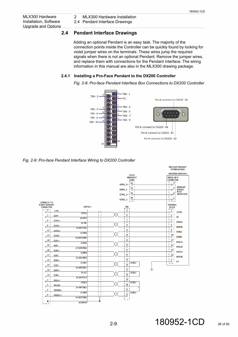
Upgrade and Options2.4 Pendant Interface Drawings
Adding an optional Pendant is an easy task. The majority of the connection points inside the Controller can be quickly found by looking for violet jumper wires on the terminals. These wires jump the required signals when there is not an optional Pendant. Remove the jumper wires, and replace them with connections for the Pendant interface. The wiring information in this manual are also in the MLX300 drawing package.
2.4.1 Installing a Pro-Face Pendant to the DX200 Controller
Fig. 2-8: Pro-face Pendant Interface Box Connections to DX200 Controller
Fig. 2-9: Pro-face Pendant Interface Wiring to DX200 Controller
2-9 180952-1CD 26 of 92
180952-1CD
2 MLX300 Hardware Installation2.4 Pendant Interface Drawings
MLX300 Hardware Installation, Software
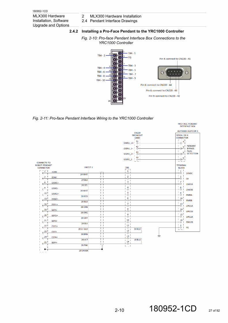
Upgrade and Options2.4.2 Installing a Pro-Face Pendant to the YRC1000 Controller
Fig. 2-10: Pro-face Pendant Interface Box Connections to the YRC1000 Controller
Fig. 2-11: Pro-face Pendant Interface Wiring to the YRC1000 Controller
2-10 180952-1CD 27 of 92

180952-1CD
2 MLX300 Hardware Installation2.4 Pendant Interface Drawings
MLX300 Hardware Installation, Software
Upgrade and Options2.4.3 Installing a MobileView Pendant to the DX200 Controller
Fig. 2-12: MobileView Pendant Interface Box Connections to the DX200 Controller
Fig. 2-13: MobileView Pendant Wiring to DX200 Controller
2-11 180952-1CD 28 of 92
180952-1CD
2 MLX300 Hardware Installation2.4 Pendant Interface Drawings
MLX300 Hardware Installation, Software
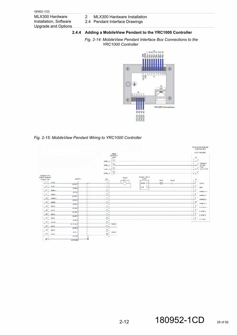
Upgrade and Options2.4.4 Adding a MobileView Pendant to the YRC1000 Controller
Fig. 2-14: MobileView Pendant Interface Box Connections to theYRC1000 Controller
Fig. 2-15: MobileView Pendant Wiring to YRC1000 Controller
2-12 180952-1CD 29 of 92
180952-1CD
2 MLX300 Hardware Installation2.5 Pendant Bypass Plug Drawings
MLX300 Hardware Installation, Software
Upgrade and Options2.5 Pendant Bypass Plug Drawings
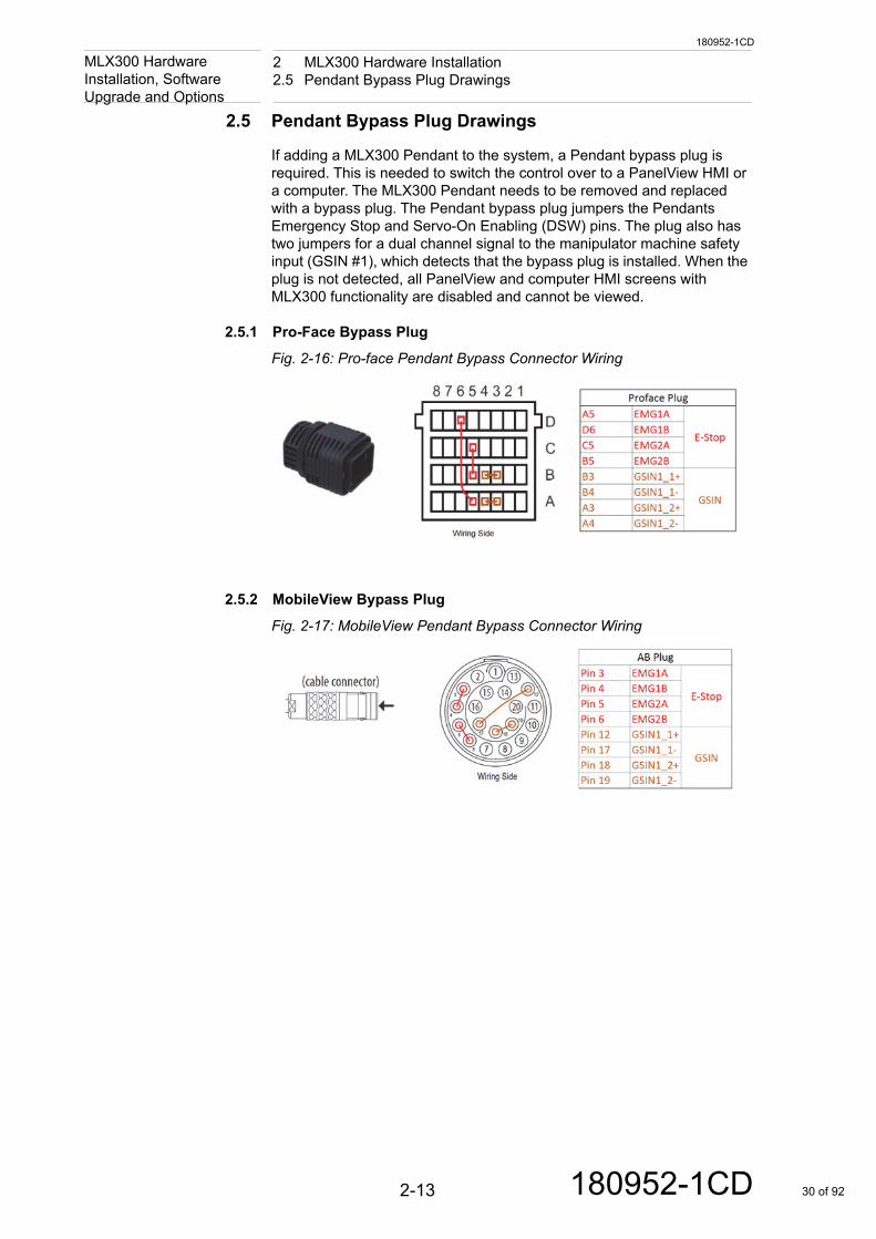
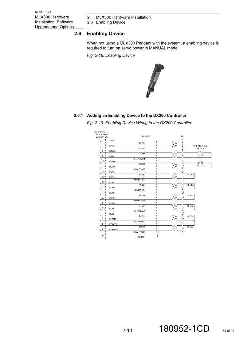
If adding a MLX300 Pendant to the system, a Pendant bypass plug is required. This is needed to switch the control over to a PanelView HMI or a computer. The MLX300 Pendant needs to be removed and replaced with a bypass plug. The Pendant bypass plug jumpers the Pendants Emergency Stop and Servo-On Enabling (DSW) pins. The plug also has two jumpers for a dual channel signal to the manipulator machine safety input (GSIN #1), which detects that the bypass plug is installed. When the plug is not detected, all PanelView and computer HMI screens with MLX300 functionality are disabled and cannot be viewed.
2.5.1 Pro-Face Bypass Plug
Fig. 2-16: Pro-face Pendant Bypass Connector Wiring
2.5.2 MobileView Bypass Plug
Fig. 2-17: MobileView Pendant Bypass Connector Wiring
2-13 180952-1CD 30 of 92
180952-1CD
2 MLX300 Hardware Installation2.6 Enabling Device
MLX300 Hardware Installation, Software
Upgrade and Options2.6 Enabling Device
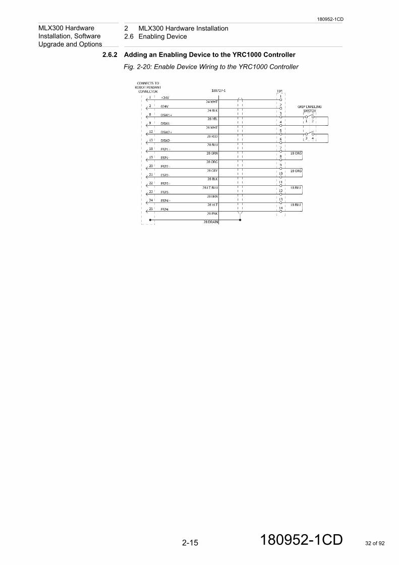
When not using a MLX300 Pendant with the system, a enabling device is required to turn on servo power in MANUAL mode.
Fig. 2-18: Enabling Device
2.6.1 Adding an Enabling Device to the DX200 Controller
Fig. 2-19: Enabling Device Wiring to the DX200 Controller
2-14 180952-1CD 31 of 92
180952-1CD
2 MLX300 Hardware Installation2.6 Enabling Device
MLX300 Hardware Installation, Software
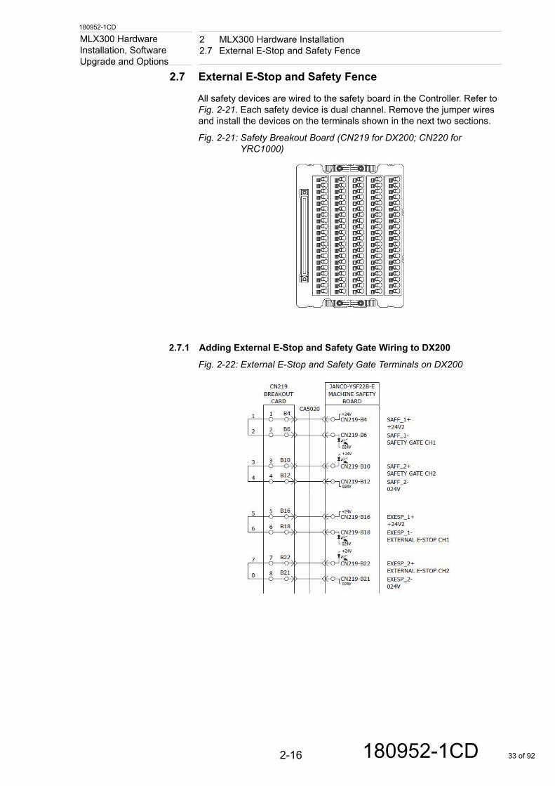
Upgrade and Options2.6.2 Adding an Enabling Device to the YRC1000 Controller
Fig. 2-20: Enable Device Wiring to the YRC1000 Controller
2-15 180952-1CD 32 of 92
180952-1CD
2 MLX300 Hardware Installation2.7 External E-Stop and Safety Fence
MLX300 Hardware Installation, Software
Upgrade and Options2.7 External E-Stop and Safety Fence
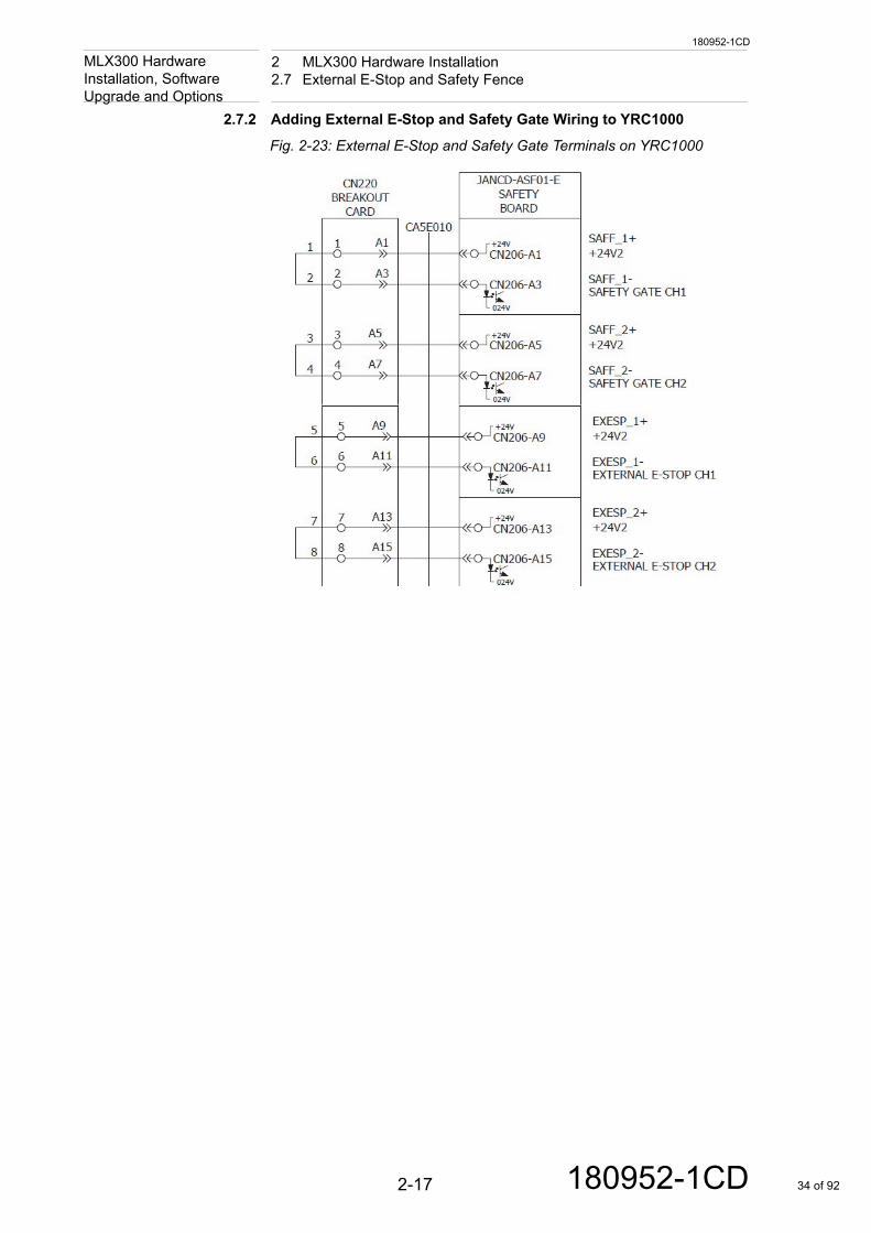
All safety devices are wired to the safety board in the Controller. Refer to Fig. 2-21. Each safety device is dual channel. Remove the jumper wires and install the devices on the terminals shown in the next two sections.
Fig. 2-21: Safety Breakout Board (CN219 for DX200; CN220 for YRC1000)
2.7.1 Adding External E-Stop and Safety Gate Wiring to DX200
Fig. 2-22: External E-Stop and Safety Gate Terminals on DX200
2-16 180952-1CD 33 of 92
180952-1CD
2 MLX300 Hardware Installation2.7 External E-Stop and Safety Fence
MLX300 Hardware Installation, Software
Upgrade and Options2.7.2 Adding External E-Stop and Safety Gate Wiring to YRC1000
Fig. 2-23: External E-Stop and Safety Gate Terminals on YRC1000
2-17 180952-1CD 34 of 92
180952-1CD
2 MLX300 Hardware Installation2.8 Controller Inputs and Outputs
MLX300 Hardware Installation, Software
Upgrade and Options2.8 Controller Inputs and Outputs
The MLX300 PLC program can control the DX200 Controller or YRC1000 Controller inputs and outputs.
Manipulator I/O wiring connections are in the MLX300 drawing package provided with the Manipulator.
2.8.1 DX200 Controller I/O
The DX200 I/O has 24 inputs and 24 outputs.
• Inputs:– Manipulator: 1-24 (sinking)– PLC: ControllerDigitalInputs.0 to .23
• Outputs:– Manipulator:
• 1-8 (sinking)• 9-24 (relays)
– PLC Outputs: • ControllerDigitalOutputs 0 to .23
Also, refer to the “Universal I/O Signal Assignment” section of the DX200 Instructions manual (165292-1CD.)
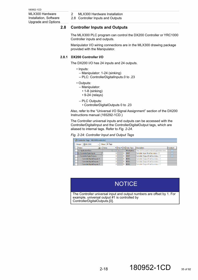
The Controller universal inputs and outputs can be accessed with the ControllerDigitalInput and the ControllerDigitalOutput tags, which are aliased to internal tags. Refer to Fig. 2-24.
Fig. 2-24: Controller Input and Output Tags
NOTICEThe Controller universal input and output numbers are offset by 1. For example, universal output #1 is controlled by ControllerDigitalOutputs.[0].
2-18 180952-1CD 35 of 92
180952-1CD
2 MLX300 Hardware Installation2.8 Controller Inputs and Outputs
MLX300 Hardware Installation, Software
Upgrade and Options2.8.2 YRC1000 Controller I/O
The YRC1000 I/O has 16 inputs and 16 outputs.
• Inputs:– Manipulator: 9-24 (sinking)– PLC: ControllerDigitalInputs.8 to .23
• Outputs:– Manipulator:
• 9-16 (sinking)• 17-24 (relays)
– PLC Outputs: • ControllerDigitalOutputs.8 to .23
Also, refer to the Read First Safety Requirements and Instruction Assembly. In this manual assembly refer to the “Robot General-Purpose I/O Signal Assignment” section of the YRC1000 Instruction manual (178642-1CD)
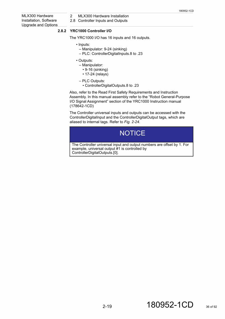
The Controller universal inputs and outputs can be accessed with the ControllerDigitalInput and the ControllerDigitalOutput tags, which are aliased to internal tags. Refer to Fig. 2-24.
NOTICEThe Controller universal input and output numbers are offset by 1. For example, universal output #1 is controlled by ControllerDigitalOutputs.[0].
2-19 180952-1CD 36 of 92
180952-1CD
3 MLX300 Software3.1 PLC Ladder Software
MLX300 Hardware Installation, Software
Upgrade and Options3 MLX300 Software
The package includes a base RSLogix5000 ladder with 43 AOIs that are specific to the Manipulator configuration and motion control. A complete set of HMI screens were developed for the Pro-face Pendant, the AB MobileView Pendant and the AB PanelViews. The HMI software can be operate a basic Manipulator, or it can be customized for a complex application. Technical tutorials on how to use the MLX HMI are available on the Motoman website.
3.1 PLC Ladder Software
The MLX300 comes with software for both the Rockwell ControlLogix and CompactLogix PLC. The “x_x_x” in the file names below is the version number.
• MLX300_CompactLogix_vx_x_x.ACD
• MLX300_ControlLogix_vx_x_x.ACD
Use Rockwell Studio 5000 Logix Designer, version 24, or newer to download the appropriate ladder to the PLC. Refer to the MLX300 Software and Operations manual for more details on how to use the AOIs to configure and move the Manipulator.
3-1 180952-1CD 37 of 92
180952-1CD
3 MLX300 Software3.2 Rockwell HMI and Pendant Software
MLX300 Hardware Installation, Software
Upgrade and Options3.2 Rockwell HMI and Pendant Software
The end user and integrator must use caution and do appropriate testing when deploying .APA files to different devices. Test each device to make sure the appropriate access is granted, paying special attention to match the criteria mentioned in this section.
FactoryTalk View project files (.APA) are provided with every MLX300 system. Two sets of files were created to help the integrator enforce “single point of control” requirements. This will be explained after the file names.
• MLX300_Pendant_MobileView_vx_x_x.APA
– As the name suggested, software should be installed in the MobileView. This Pendant will allow access to all of the jogging and teaching features available. There will be no limitation to screen access when the appropriate user login is used.
• MLX300_HMI_PCorPanelView_vx_x_x.APA
– This software must be installed in any remote stations, such as PanelView HMIs, or computer. The MLX300 screens in this HMI software will be disable and invisible when a Pendant is connected. The intent here is enforce “single point of control”, by allowing only one interface to jog the Manipulator. To access the MLX300 screens in this software, the Programming Pendant must be disconnected, the MLX300 Pendant must be disconnected, and the MLX300 Pendant bypass plug must be installed. The Pendant bypass plug provides dual channel signals to the Controllers machine safety inputs. It is critical that only this software is used in PanelView stations!
Use Factory Talk View Studio - Machine Edition, version 7.0 or higher to download the screens to the HMI. The default resolution of the MLX300 HMI Project is 640x480. This should be changed to match the desired resolution for the MobileView (1280x800). This can be done under the “Project Settings” in Factory Talk View Studio, after making the change all screens will automatically scale to the new size.
CAUTION
• End user and integrator must do appropriate testing when deploying .APA files to different devices.
This responsibility lies entirely on the end user and integrator.
NOTICE• It is up to the integrator or end user to perform a risk assessment,
before placing the system into production.
• The default password for the expert login is no password.
3-2 180952-1CD 38 of 92
180952-1CD
3 MLX300 Software3.2 Rockwell HMI and Pendant Software
MLX300 Hardware Installation, Software
Upgrade and Options3.2.1 MobileView Settings
A few other settings in the MobileView should be changed. The project file that is loaded into the MobileView includes momentary push button functionality. When the buttons are pressed for a long time, the default interaction is for this to act as a “right mouse click.” It is desirable to change this functionality.
These settings are described in the Rockwell's manual and are also listed here to draw attention. Any documentation in the Rockwell manual or documentation should override the procedure or screenshots that follow.
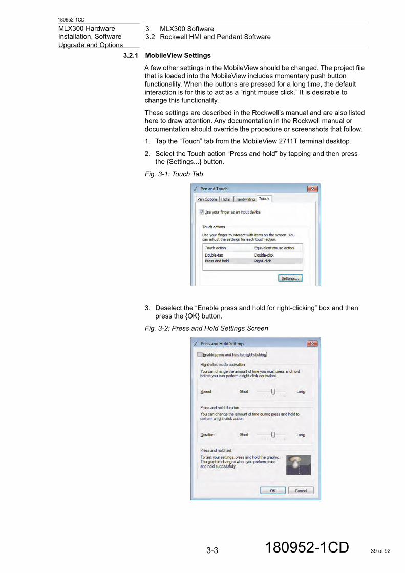
1. Tap the “Touch” tab from the MobileView 2711T terminal desktop.
2. Select the Touch action “Press and hold” by tapping and then press the {Settings...} button.
Fig. 3-1: Touch Tab
3. Deselect the “Enable press and hold for right-clicking” box and then press the {OK} button.
Fig. 3-2: Press and Hold Settings Screen
3-3 180952-1CD 39 of 92
180952-1CD
3 MLX300 Software3.3 Pro-face HMI and Pendant Software
MLX300 Hardware Installation, Software
Upgrade and Options4. Tap the {Apply} button on the “Touch” tab.
5. Enable EWF to save the settings by referring to page 35 of the Rockwell manual for details on how to manipulate this feature.
3.3 Pro-face HMI and Pendant Software
The Pro-face HMI screens are almost identical to the Rockwell MoblieView screens. One difference is the jog buttons are dedicated to the buttons on the sides of the Pendant, instead of on the touch screen.
• MLX300_Pendant_Proface_vx_x_x–This software is for the Pro-face Pendant, Motoman part number
182097-1
• MLX300_HMI_Proface_vx_x_x–This software is for the Pro-face HMI, which could be any SP5000
series display.
Use Pro-face GP-Pro EX, version 4.06.300 or higher to download the software to the Pendant.
NOTICEThe right-click functionality for the touch screen is now disabled
NOTICEThe default password for the expert login is “EXPERT1”. The Pro-face HMI password is different than the Rockwell HMI password, because it requires a number.
3-4 180952-1CD 40 of 92
180952-1CD
4 Collision Detection Setup4.1 Summary of Operations to Change Collision Detection
MLX300 Hardware Installation, Software
Upgrade and Options4 Collision Detection Setup
The collision detection feature is setup with default values at Yaskawa before shipment. It is possible to make the settings more sensitive for the actual application. Once the production cycle is operating, the programmer can observe the maximum monitored torque values for each axis, and enter new detection levels.
4.1 Summary of Operations to Change Collision Detection
The collision detection settings can be viewed and adjusted only with the Programming Pendant. Follow the steps below to monitor and make adjustments.
1. With the power off, connect the Programming Pendant, and turn power on.
2. Disconnect the Pendant communication using procedures in Appendix A.1 "Method to Disconnect Programming Pendant with Software".
3. With the Pendant key-switch set to REMOTE, and the MLX300 key-switch set to AUTO mode, cycle the production sequence for 30 minutes to warm-up the Manipulator. The MLX300 jobs cannot be started with the MLX300 Pendant, since it is not connected. The jobs can be started with an HMI display or computer. (Refer to section 2.1 “MLX300 Hardware Configurations” on page 2-1)
4. Connect the Programming Pendant communication with the procedure in Appendix A.2 "Method to Reconnect Programming Pendant with Software".
5. Switch the Programming Pendant key-switch to TEACH mode.
6. Referring to section 4.2 “Login as Manager” and section 4.3 “Collision Detection Setting - AUTO Mode”, clear the detection level of all axes.
7. Disconnect the Programming Pendant communication.
8. With the Programming Pendant key-switch in REMOTE, and the MLX300 key-switch in AUTO, cycle the production sequence for 15 minutes, or enough time to get a good maximum disturbance feedback.
9. Connect the Programming Pendant communication.
10. Switch the Programming Pendant key-switch to TEACH mode
11. Referring to section 4.2 through section 4.4, enter the new detection levels of all axes. Use condition file #8 for AUTO mode settings and #9 for MANUAL mode settings.
NOTICEHigher collision detection settings are used internally when the Manipulator is cold after a power-up. This will compensate for the changes in grease viscosity as the Manipulator warms up. The grease needs to be warmed up to be able to get valid readings. It is important to cycle the Manipulator for over 30 minutes, before setting up collision detection. During the warm-up period, collision detection alarms will not work until the detection levels increase above the setting plus the internal offset.
4-1 180952-1CD 41 of 92
180952-1CD
4 Collision Detection Setup4.2 Login as Manager
MLX300 Hardware Installation, Software
Upgrade and Options4.2 Login as Manager
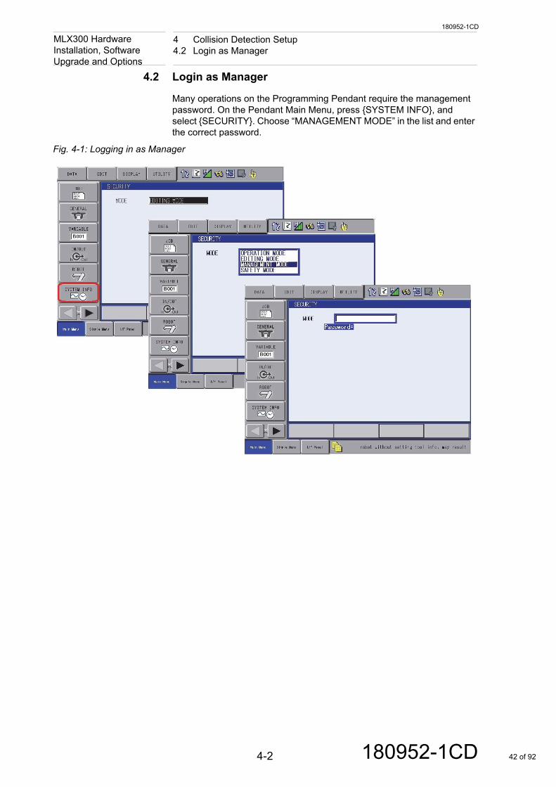
Many operations on the Programming Pendant require the management password. On the Pendant Main Menu, press {SYSTEM INFO}, and select {SECURITY}. Choose “MANAGEMENT MODE” in the list and enter the correct password.
Fig. 4-1: Logging in as Manager
4-2 180952-1CD 42 of 92
180952-1CD
4 Collision Detection Setup4.3 Collision Detection Setting - AUTO Mode
MLX300 Hardware Installation, Software
Upgrade and Options4.3 Collision Detection Setting - AUTO Mode
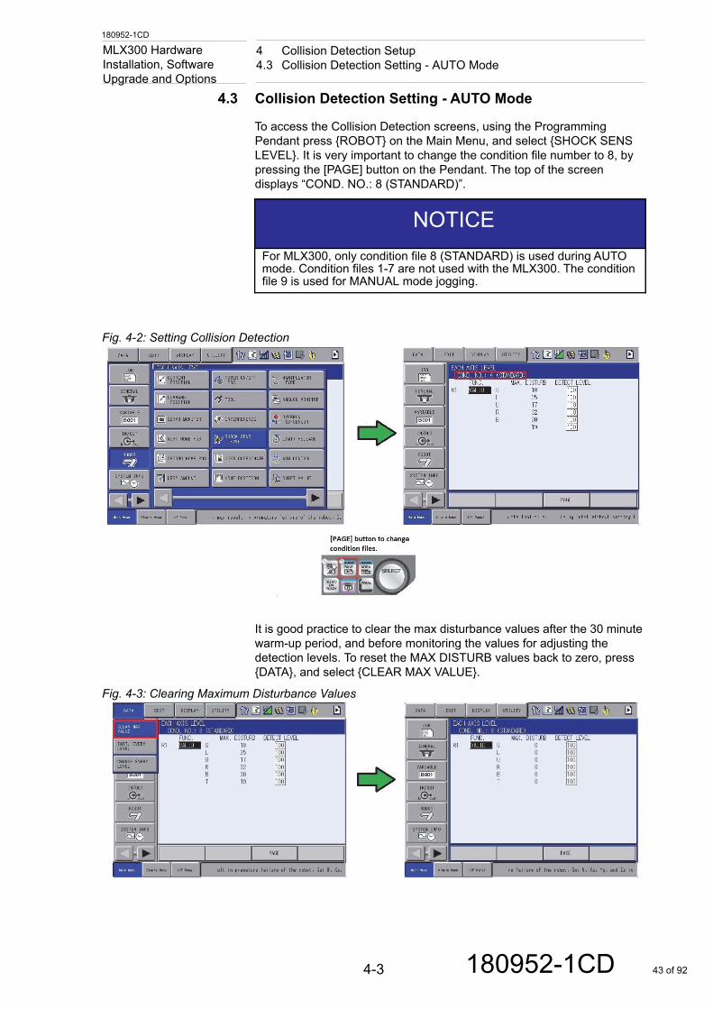
To access the Collision Detection screens, using the Programming Pendant press {ROBOT} on the Main Menu, and select {SHOCK SENS LEVEL}. It is very important to change the condition file number to 8, by pressing the [PAGE] button on the Pendant. The top of the screen displays “COND. NO.: 8 (STANDARD)”.
Fig. 4-2: Setting Collision Detection
It is good practice to clear the max disturbance values after the 30 minute warm-up period, and before monitoring the values for adjusting the detection levels. To reset the MAX DISTURB values back to zero, press {DATA}, and select {CLEAR MAX VALUE}.
Fig. 4-3: Clearing Maximum Disturbance Values
NOTICEFor MLX300, only condition file 8 (STANDARD) is used during AUTO mode. Condition files 1-7 are not used with the MLX300. The condition file 9 is used for MANUAL mode jogging.
4-3 180952-1CD 43 of 92

180952-1CD
4 Collision Detection Setup4.3 Collision Detection Setting - AUTO Mode
MLX300 Hardware Installation, Software
Upgrade and OptionsRun the production sequence for a multiple of cycles to get good feedback for the “MAX DISTURB” column. The max disturbance is the monitored max torque for each axis. The “DETECT LEVEL” settings for each axis can be adjusted to make it more sensitive. It is recommended to make the detection settings 15 higher than the maximum disturbance values monitored.
Fig. 4-4: Setting Detection Level
NOTICEThe DETECT LEVEL range is 0-300. 100 is the factory default.
4-4 180952-1CD 44 of 92
180952-1CD
4 Collision Detection Setup4.4 Collision Detection Setting - TEACH Mode
MLX300 Hardware Installation, Software
Upgrade and Options4.4 Collision Detection Setting - TEACH Mode
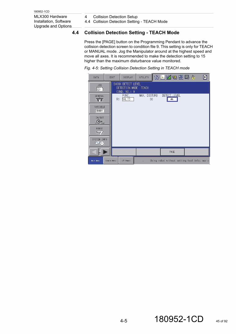
Press the [PAGE] button on the Programming Pendant to advance the collision detection screen to condition file 9. This setting is only for TEACH or MANUAL mode. Jog the Manipulator around at the highest speed and move all axes. It is recommended to make the detection setting to 15 higher than the maximum disturbance value monitored.
Fig. 4-5: Setting Collision Detection Setting in TEACH mode
4-5 180952-1CD 45 of 92
5-1
180952-1CD
180952-1CD
5 Soft Limits AdjustmentsMLX300 Hardware Installation, Software Upgrade and Options
5 Soft Limits Adjustments
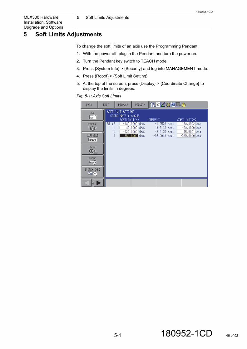
To change the soft limits of an axis use the Programming Pendant.
1. With the power off, plug in the Pendant and turn the power on.
2. Turn the Pendant key switch to TEACH mode.
3. Press {System Info} > {Security} and log into MANAGEMENT mode.
4. Press {Robot} > {Soft Limit Setting}
5. At the top of the screen, press {Display} > {Coordinate Change} to display the limits in degrees.
Fig. 5-1: Axis Soft Limits
46 of 92
6-1
180952-1CD
180952-1CD
6 Brake ReleaseMLX300 Hardware Installation, Software Upgrade and Options
6 Brake Release
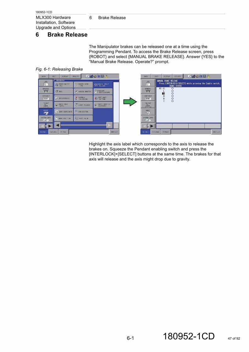
The Manipulator brakes can be released one at a time using the Programming Pendant. To access the Brake Release screen, press {ROBOT} and select {MANUAL BRAKE RELEASE}. Answer {YES} to the “Manual Brake Release. Operate?” prompt.
Fig. 6-1: Releasing Brake
Highlight the axis label which corresponds to the axis to release the brakes on. Squeeze the Pendant enabling switch and press the [INTERLOCK]+[SELECT] buttons at the same time. The brakes for that axis will release and the axis might drop due to gravity.
47 of 92
180952-1CD
7 Shipping PositionMLX300 Hardware Installation, Software
Upgrade and Options7 Shipping Position
Before shipping a Manipulator to a different location, place the Manipulator in its standard shipping position. Reference the Manipulator Instructions for details concerning position and shipping brackets.
Use the Programming Pendant to move the Manipulator into the shipping position.
1. With the power off, plug in the Pendant and turn power on.
2. Turn the Pendant key switch to TEACH mode.
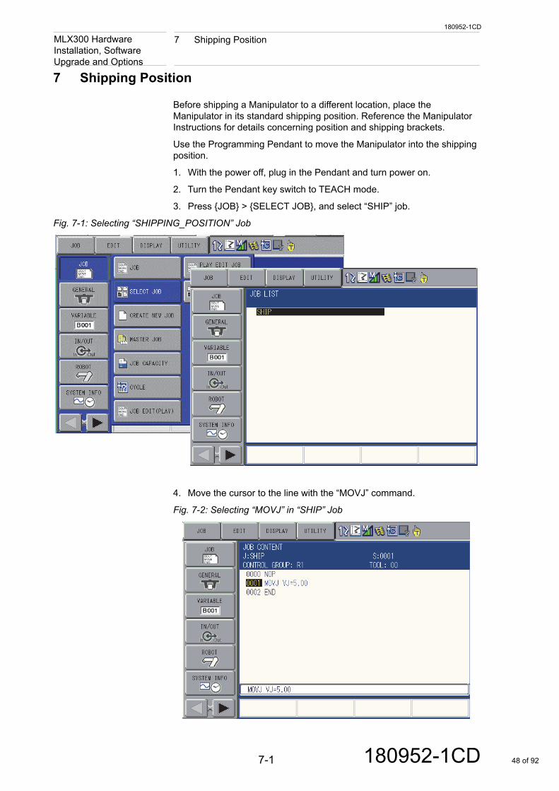
3. Press {JOB} > {SELECT JOB}, and select “SHIP” job.
Fig. 7-1: Selecting “SHIPPING_POSITION” Job
4. Move the cursor to the line with the “MOVJ” command.
Fig. 7-2: Selecting “MOVJ” in “SHIP” Job
7-1 180952-1CD 48 of 92
180952-1CD
7 Shipping PositionMLX300 Hardware Installation, Software
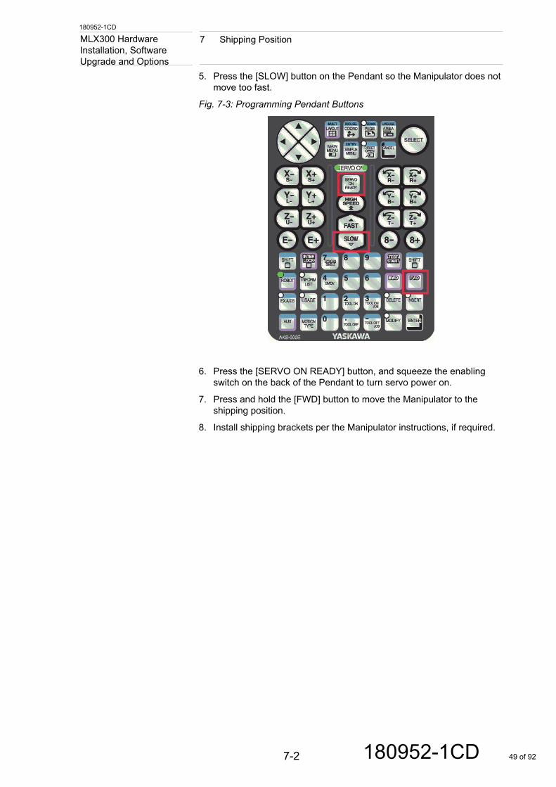
Upgrade and Options5. Press the [SLOW] button on the Pendant so the Manipulator does not move too fast.
Fig. 7-3: Programming Pendant Buttons
6. Press the [SERVO ON READY] button, and squeeze the enabling switch on the back of the Pendant to turn servo power on.
7. Press and hold the [FWD] button to move the Manipulator to the shipping position.
8. Install shipping brackets per the Manipulator instructions, if required.
7-2 180952-1CD 49 of 92
180952-1CD
8 MLX300 PLC Software Version Upgrade Procedure8.1 Export Manipulator Application Data from RSLogix Ladder
MLX300 Hardware Installation, Software
Upgrade and Options8 MLX300 PLC Software Version Upgrade Procedure
Follow the steps below when installing a new MLX300 PLC software version. By following the steps below all the application data will be save and restored.
8.1 Export Manipulator Application Data from RSLogix Ladder
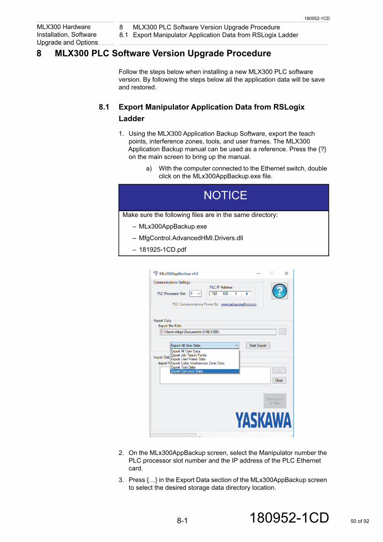
1. Using the MLX300 Application Backup Software, export the teach points, interference zones, tools, and user frames. The MLX300 Application Backup manual can be used as a reference. Press the {?} on the main screen to bring up the manual.
a) With the computer connected to the Ethernet switch, double click on the MLx300AppBackup.exe file.
2. On the MLx300AppBackup screen, select the Manipulator number the PLC processor slot number and the IP address of the PLC Ethernet card.
3. Press {…} in the Export Data section of the MLx300AppBackup screen to select the desired storage data directory location.
NOTICEMake sure the following files are in the same directory:
– MLx300AppBackup.exe
– MfgControl.AdvancedHMI.Drivers.dll
– 181925-1CD.pdf
8-1 180952-1CD 50 of 92
180952-1CD
8 MLX300 PLC Software Version Upgrade Procedure8.2 Export non-MLX Tasks from the RSLogix Ladder
MLX300 Hardware Installation, Software
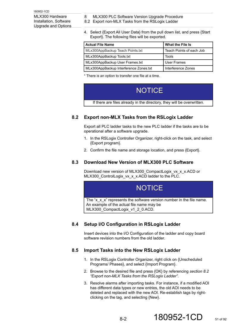
Upgrade and Options4. Select {Export All User Data} from the pull down list, and press {Start Export}. The following files will be exported.
* There is an option to transfer one file at a time.
8.2 Export non-MLX Tasks from the RSLogix Ladder
Export all PLC ladder tasks to the new PLC ladder if the tasks are to be operational after a software upgrade.
1. In the RSLogix Controller Organizer, right-click on the task, and select {Export program}.
2. Confirm the file name and storage location, and press {Export}.
8.3 Download New Version of MLX300 PLC Software
Download new version of MLX300_CompactLogix_vx_x_x.ACD or MLX300_ControlLogix_vx_x_x.ACD ladder to the PLC.
8.4 Setup I/O Configuration in RSLogix Ladder
Insert devices into the I/O Configuration of the ladder and copy board software revision numbers from the old ladder.
8.5 Import Tasks into the New RSLogix Ladder
1. In the RSLogix Controller Organizer, right click on {Unscheduled Programs/ Phases}, and select {Import Program}.
2. Browse to the desired file and press {OK} by referencing section 8.2 “Export non-MLX Tasks from the RSLogix Ladder”.
3. Resolve alarms after importing tasks. For instance, if a modified AOI has different data types or new entries, the old AOI needs to be deleted and replaced with the new AOI. Re-establish tags by right-clicking on the tag, and selecting {New}.
Actual File Name What the File IsMLx300AppBackup Teach Points.txt Teach Points of each JobMLx300AppBackup Tools.txt ToolsMLx300AppBackup User Frames.txt User FramesMLx300AppBackup Interference Zones.txt Interference Zones
NOTICEIf there are files already in the directory, they will be overwritten.
NOTICEThe “x_x_x” represents the software version number in the file name. An example of the actual file name may be MLX300_CompactLogix_v1_2_0.ACD.
8-2 180952-1CD 51 of 92
180952-1CD
8 MLX300 PLC Software Version Upgrade Procedure8.6 Import the Manipulator Application Data into the PLC Ladder
MLX300 Hardware Installation, Software
Upgrade and Options8.6 Import the Manipulator Application Data into the PLC Ladder
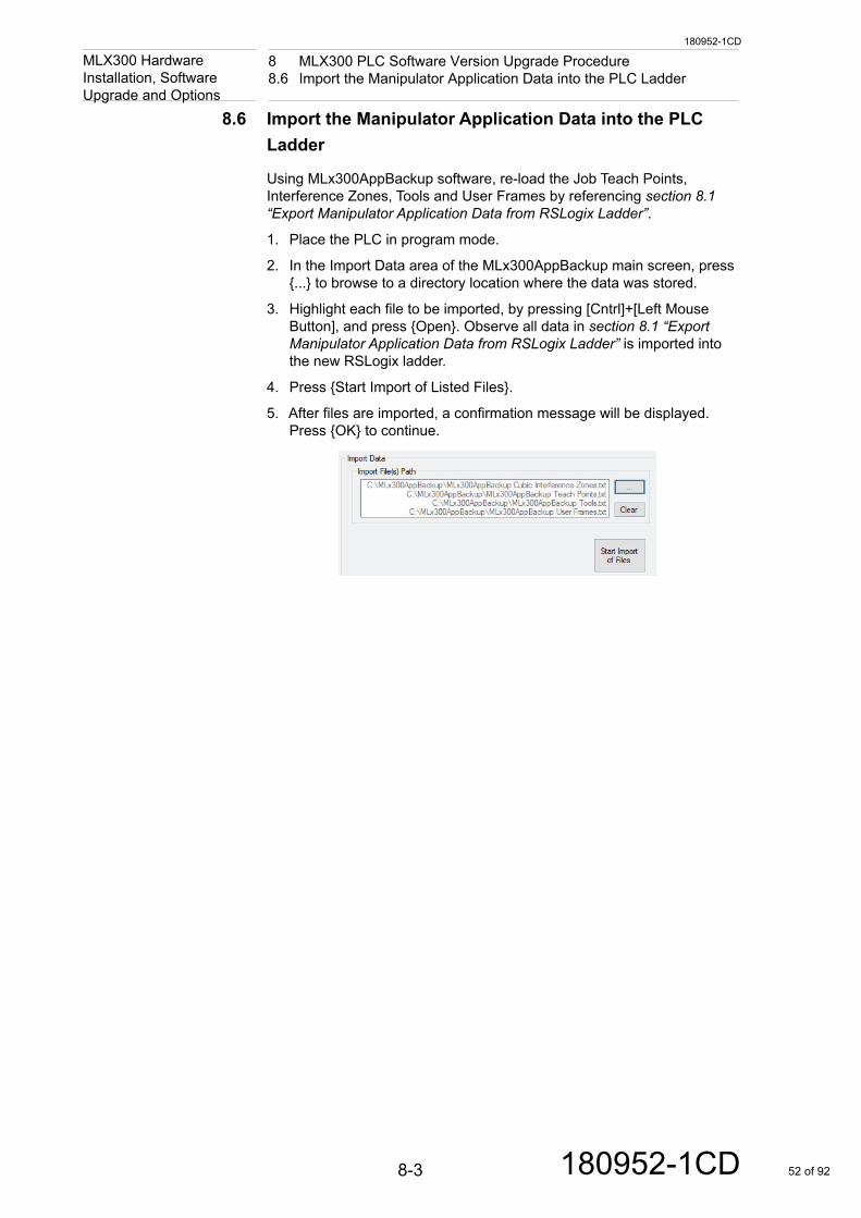
Using MLx300AppBackup software, re-load the Job Teach Points, Interference Zones, Tools and User Frames by referencing section 8.1 “Export Manipulator Application Data from RSLogix Ladder”.
1. Place the PLC in program mode.
2. In the Import Data area of the MLx300AppBackup main screen, press {...} to browse to a directory location where the data was stored.
3. Highlight each file to be imported, by pressing [Cntrl]+[Left Mouse Button], and press {Open}. Observe all data in section 8.1 “Export Manipulator Application Data from RSLogix Ladder” is imported into the new RSLogix ladder.
4. Press {Start Import of Listed Files}.
5. After files are imported, a confirmation message will be displayed.Press {OK} to continue.
8-3 180952-1CD 52 of 92
180952-1CD
9 Motosim EG-VRC Virtual Controller Setup Procedure9.1 Pre-requisites
MLX300 Hardware Installation, Software
Upgrade and Options9 Motosim EG-VRC Virtual Controller Setup Procedure
9.1 Pre-requisites
• MotoSim EG-VRC 2015 License or newer
–MotoSim EG-VRC needs a valid License dongle
• Manipulator Controller settings
–Network Ethernet Server - Must be active and have correct IP settings
–Ethernet Server - Must be active
• Manipulator parameters (Already set before shipment)
–S1D199 = 1 - Using absolute feedback data
–Pseudo Input 87015 = ON CMD REMOTE SEL
9.2 Debug Mode for Simulation
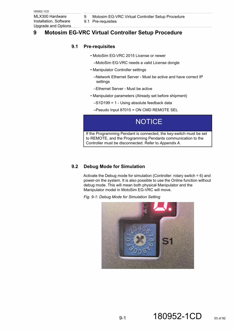
Activate the Debug mode for simulation (Controller: rotary switch = 6) and power-on the system. It is also possible to use the Online function without debug mode. This will mean both physical Manipulator and the Manipulator model in MotoSim EG-VRC will move.
Fig. 9-1: Debug Mode for Simulation Setting
NOTICEIf the Programming Pendant is connected, the key-switch must be set to REMOTE, and the Programming Pendants communication to the Controller must be disconnected. Refer to Appendix A.
9-1 180952-1CD 53 of 92
180952-1CD
9 Motosim EG-VRC Virtual Controller Setup Procedure9.3 Create a MotoSim EG-VRC Project
MLX300 Hardware Installation, Software
Upgrade and Options9.3 Create a MotoSim EG-VRC Project
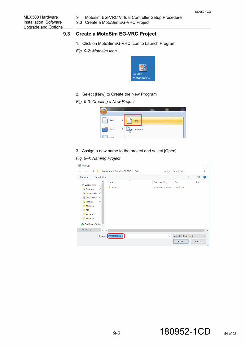
1. Click on MotoSimEG-VRC Icon to Launch Program
Fig. 9-2: Motosim Icon
2. Select [New] to Create the New Program
Fig. 9-3: Creating a New Project
3. Assign a new name to the project and select [Open]
Fig. 9-4: Naming Project
9-2 180952-1CD 54 of 92
180952-1CD
9 Motosim EG-VRC Virtual Controller Setup Procedure9.3 Create a MotoSim EG-VRC Project
MLX300 Hardware Installation, Software
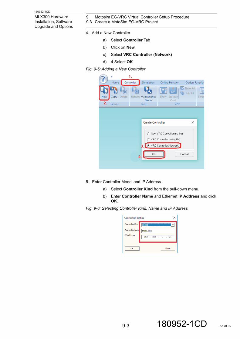
Upgrade and Options4. Add a New Controller
a) Select Controller Tab
b) Click on New
c) Select VRC Controller (Network)
d) 4.Select OK
Fig. 9-5: Adding a New Controller
5. Enter Controller Model and IP Address
a) Select Controller Kind from the pull-down menu.
b) Enter Controller Name and Ethernet IP Address and click OK.
Fig. 9-6: Selecting Controller Kind, Name and IP Address
9-3 180952-1CD 55 of 92
180952-1CD
9 Motosim EG-VRC Virtual Controller Setup Procedure9.3 Create a MotoSim EG-VRC Project
MLX300 Hardware Installation, Software
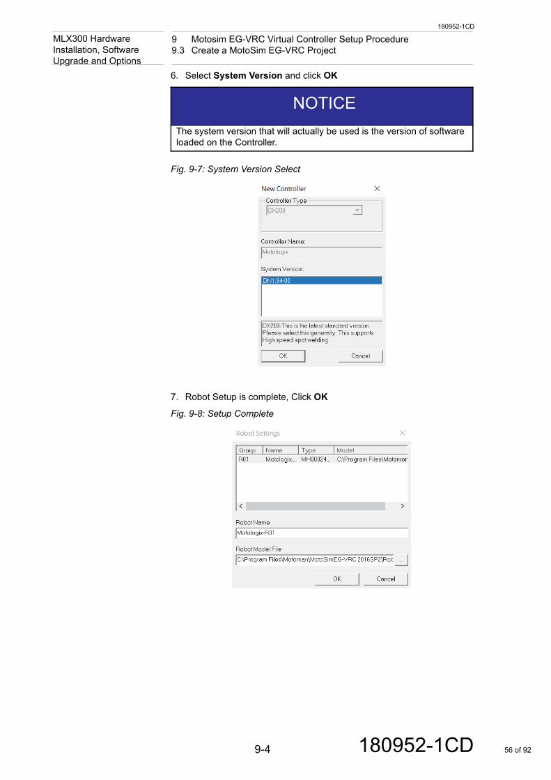
Upgrade and Options6. Select System Version and click OK
Fig. 9-7: System Version Select
7. Robot Setup is complete, Click OK
Fig. 9-8: Setup Complete
NOTICEThe system version that will actually be used is the version of software loaded on the Controller.
9-4 180952-1CD 56 of 92
180952-1CD
9 Motosim EG-VRC Virtual Controller Setup Procedure9.3 Create a MotoSim EG-VRC Project
MLX300 Hardware Installation, Software
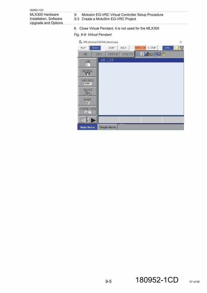
Upgrade and Options8. Close Virtual Pendant, it is not used for the MLX300
Fig. 9-9: Virtual Pendant
9-5 180952-1CD 57 of 92
180952-1CD
9 Motosim EG-VRC Virtual Controller Setup Procedure9.4 Starting Online Function
MLX300 Hardware Installation, Software
Upgrade and Options9.4 Starting Online Function
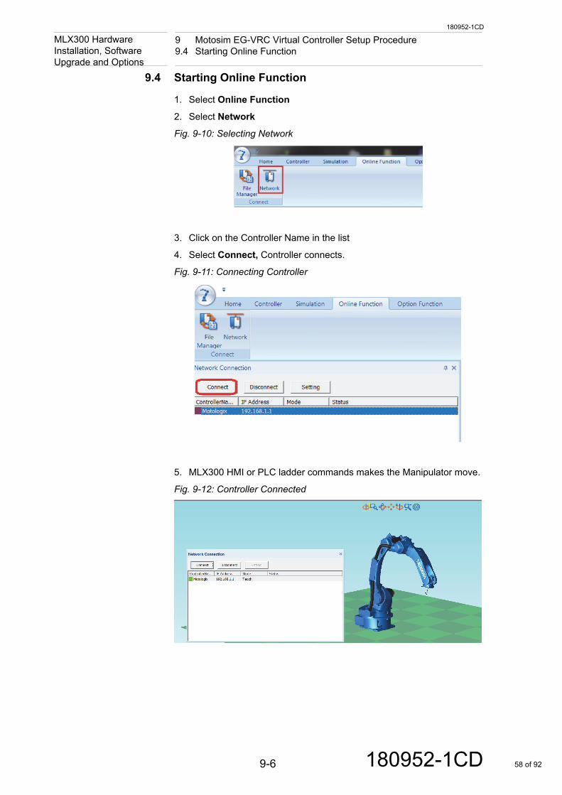
1. Select Online Function
2. Select Network
Fig. 9-10: Selecting Network
3. Click on the Controller Name in the list
4. Select Connect, Controller connects.
Fig. 9-11: Connecting Controller
5. MLX300 HMI or PLC ladder commands makes the Manipulator move.
Fig. 9-12: Controller Connected
9-6 180952-1CD 58 of 92
180952-1CD
9 Motosim EG-VRC Virtual Controller Setup Procedure9.5 Option to use Motosim with the Manipulator Disconnected
MLX300 Hardware Installation, Software
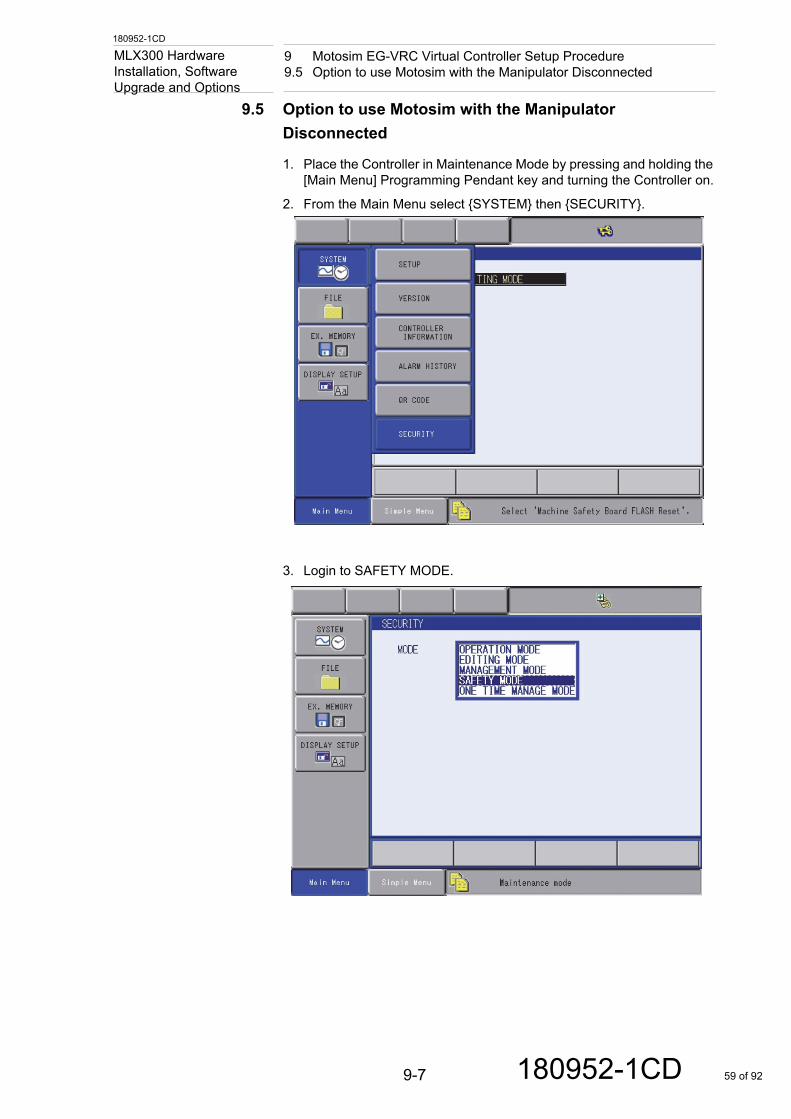
Upgrade and Options9.5 Option to use Motosim with the Manipulator Disconnected
1. Place the Controller in Maintenance Mode by pressing and holding the [Main Menu] Programming Pendant key and turning the Controller on.
2. From the Main Menu select {SYSTEM} then {SECURITY}.
3. Login to SAFETY MODE.
9-7 180952-1CD 59 of 92
180952-1CD
9 Motosim EG-VRC Virtual Controller Setup Procedure9.5 Option to use Motosim with the Manipulator Disconnected
MLX300 Hardware Installation, Software
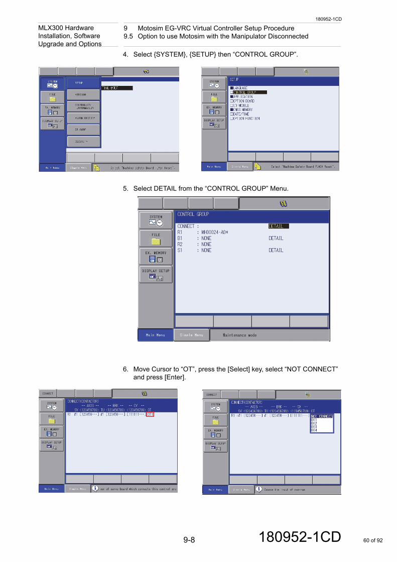
Upgrade and Options4. Select {SYSTEM}, {SETUP} then “CONTROL GROUP”.
5. Select DETAIL from the “CONTROL GROUP” Menu.
6. Move Cursor to “OT”, press the [Select] key, select “NOT CONNECT” and press [Enter].
9-8 180952-1CD 60 of 92
180952-1CD
9 Motosim EG-VRC Virtual Controller Setup Procedure9.5 Option to use Motosim with the Manipulator Disconnected
MLX300 Hardware Installation, Software
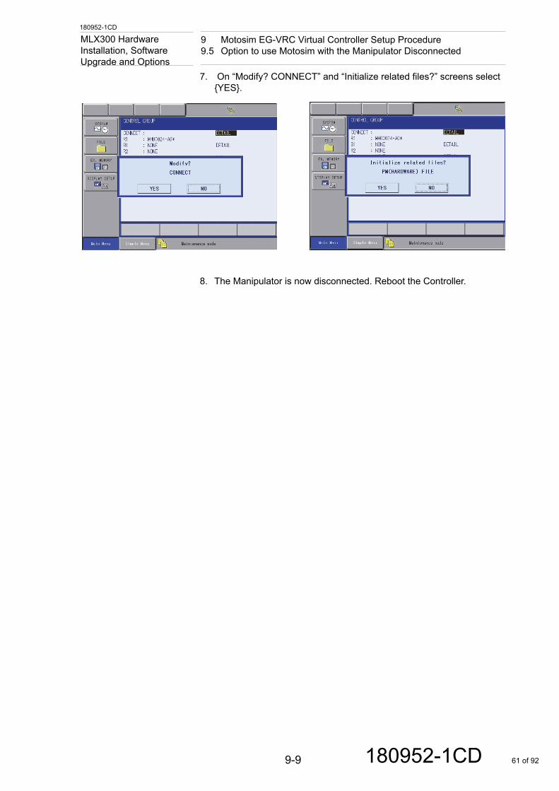
Upgrade and Options7. On “Modify? CONNECT” and “Initialize related files?” screens select {YES}.
8. The Manipulator is now disconnected. Reboot the Controller.
9-9 180952-1CD 61 of 92
180952-1CD
Appendix AA.1 Method to Disconnect Programming Pendant with Software
MLX300 Hardware Installation, Software
Upgrade and OptionsAppendix A
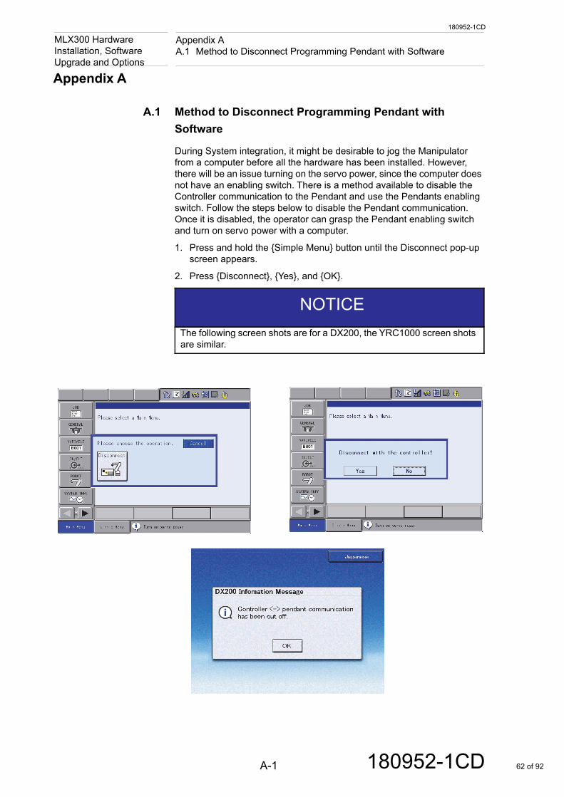
A.1 Method to Disconnect Programming Pendant with Software
During System integration, it might be desirable to jog the Manipulator from a computer before all the hardware has been installed. However, there will be an issue turning on the servo power, since the computer does not have an enabling switch. There is a method available to disable the Controller communication to the Pendant and use the Pendants enabling switch. Follow the steps below to disable the Pendant communication. Once it is disabled, the operator can grasp the Pendant enabling switch and turn on servo power with a computer.
1. Press and hold the {Simple Menu} button until the Disconnect pop-up screen appears.
2. Press {Disconnect}, {Yes}, and {OK}.
NOTICEThe following screen shots are for a DX200, the YRC1000 screen shots are similar.
A-1 180952-1CD 62 of 92
180952-1CD
Appendix AA.2 Method to Reconnect Programming Pendant with Software
MLX300 Hardware Installation, Software
Upgrade and OptionsA.2 Method to Reconnect Programming Pendant with Software
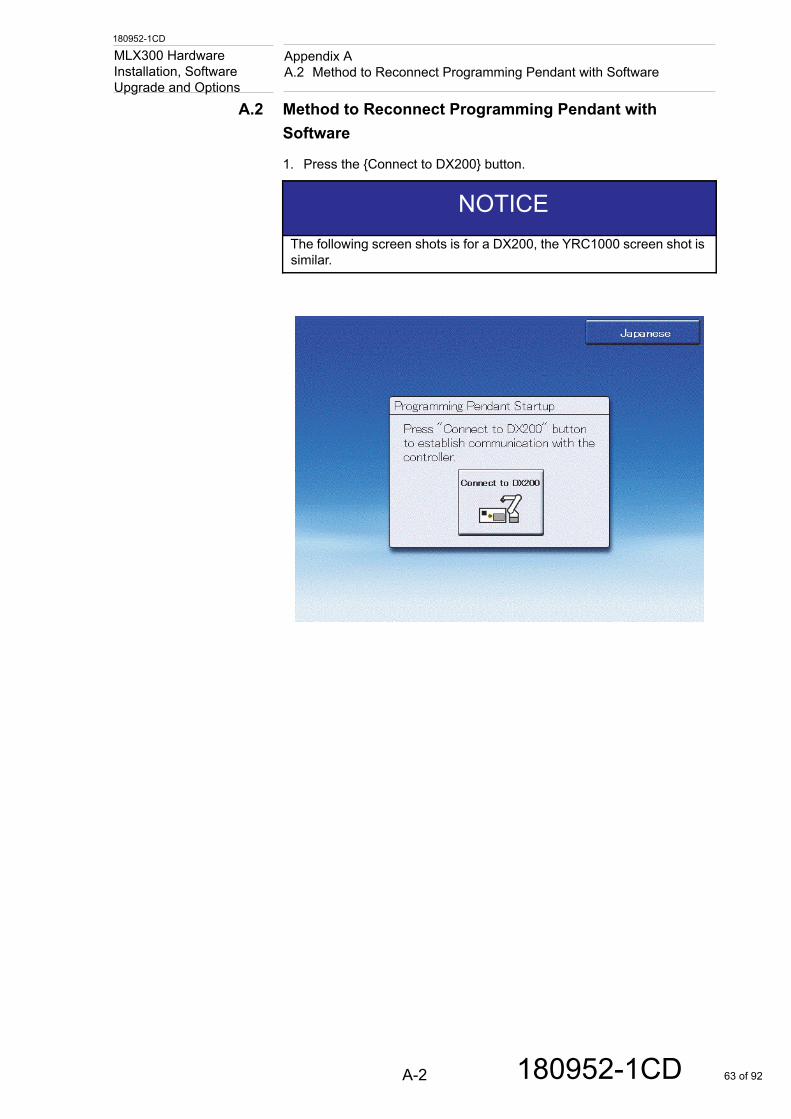
1. Press the {Connect to DX200} button.
NOTICEThe following screen shots is for a DX200, the YRC1000 screen shot is similar.
A-2 180952-1CD 63 of 92
180247-1CD
Appendix B3
MLX300
Appendix B
B.1 Glossary
3
3D Graphic Display FunctionThe 3D Graphic Display Function (this will be called 3D Display Function) is that, a 3D model of the Manipulator is displayed on the Programming Pendant window, and the current value of the Manipulator can be confirmed. By using the multi-window function, the job's teaching position displayed in the job content can also be confirmed on the 3D display window. When the functional safety function is valid, the functional safety range can also be displayed.
A
Absolute Data (ABSO Data)Absolute Data (ABSO Data) is a correction factor for data that establishes an indicated value of zero when the Manipulator is at the predetermined Home (calibration position).
AC BitAOI output bit that turns on when motion begins executing and off when motion completes.
AccuracyAccuracy is the measurement of the deviation between the command characteristic and the attained characteristic (R15.05-2), or the precision with which a computed or calculated Manipulator position can be attained. Accuracy is normally worse than the arm's repeatability. Accuracy is not constant over the workspace, due to the effect of link kinematics.
Active Compliant RobotAn active compliant Manipulator is one in which motion modification during the performance of a task is initiated by the control system. The induced motion modification is slight, but sufficient to facilitate the completion of a desired task.
Actual PositionThe position or location of the tool control point. Note that this will not be exactly the same as the demand position, due to a multitude of unsensed errors, such as link deflection, transmission irregularity, tolerances in link lengths, etc.
ActuatorA power mechanism used to effect motion, or maintain position of the Manipulator (for example, a motor which converts electrical energy to effect motion of the Manipulator) (R15.07). The actuator responds to a signal received from the control system.
Add on Instruction (AOI)An Add On Instruction is a custom function block that can be inserted into a Rockwell PLC ladder.
B-1 180247-1CD 64 of 92
180247-1CD
Appendix BB
MLX300
AlgorithmsSelf-contained step-by-step set of instructions to perform
ANSI/RIA R15.06-2012 American National Standard for Industrial Robots and Robot SystemsThis standard provides guidelines for the manufacture and integration of Industrial Robots and Robot Systems with emphasis on their safe use, the importance of risk assessment and establishing personnel safety. This standard is a national adoption of the International Standards ISO 10218-1 and ISO 10218-2 for Industrial Robots and Robot Systems, and offers a global safety standard for the manufacture and integration of such systems.
APA Files See Factory Talk View
ArcWorldRobotic welding systems delivering flexible integrated robotics into the welding processes. ArcWorlds can be configured with multiple Manipulators, a heavy-duty Positioner or servo-controlled external axes for coordinated motion.
Automatic ModeSee "Play Mode".
AxisA direction used to specify the Manipulator motion in a linear or rotary mode. (ISO 8373)
Axis BacklashPlay between drive train gears
Axis InterferenceThe Axis Interference Area is a function that judges the current position of each axis and outputs a signal based on whether the current position is within a predefined range.
B
BaseThe stable platform to which an industrial robotic arm is attached.
Base Coordinate SystemThe Base Coordinate System (sometimes referred to as World Coordinate System) defines a common reference point for a cell or application. This is useful when using multiple Manipulators or devices as positions defined in Base Coordinates will be the same for all Manipulators and devices.
Burn-inBurn-In is a Manipulator testing procedure where all components of the Manipulator are operated continuously for an extended period of time. This is done to test movement and movement programming of the Manipulator at early stages to avoid malfunctions after deployment.
Bypass PlugProvides dual channel signals to the Controllers machine safety inputs
B-2 180247-1CD 65 of 92
180247-1CD
Appendix BC
MLX300
C
Computer Aided Design (CAD)Computer Aided Design (CAD). Computer graphic applications designed to allow engineering of objects (or parts), which are to be manufactured. A computer is used as a tool to design schematics and produce blueprints, which enable the accurate production of the object. The CAD system enables the three dimensional drawings of basic figures, exact sizing and placement of components, making lines of specified length, width, or angle, as well as satisfying varying geometric shapes. This system also allows the designer to test a simulated part under different stresses, loads, etc.
Cartesian CoordinatesCartesian Coordinates is a type of coordinate system that specifies the location of a point in two dimensional space by a pair of numerical numbers, which further specify the distance to fixed axes that are perpendicular to each other. In simple terms, an XY graph represents a two dimensional Cartesian Coordinate System. When a point is specified in a three dimensional space (XYZ graph), it constitutes a three dimensional Cartesian coordinate system. A Manipulator’s TCP position is specified in a Cartesian Coordinate.
Cartesian ManipulatorA Cartesian Manipulator is a Manipulator arm with prismatic joints, which allows movement along one or more of the three- axes in the X, Y, Z coordinate system.
Cartesian TopologyA topology, which uses prismatic joints throughout, normally arranged to be perpendicular to each other.
Cartesian-coordinate RobotA Cartesian-coordinate Robot is a Manipulator whose Manipulator-arm degrees of freedom are defined by Cartesian Coordinates. This describes motions that are east-west, north-south and up-down, as well as rotary motions to change orientation.
Category 3 (Cat3)Category 3 (Cat 3) means that the safety related parts of the control system will be designed so that:
• Single faults will not prevent the safety function from working correctly.
• Single faults will be detected at or before the next demand of the safety function.
• When a single fault does occur, a safe state shall be maintained until the detected fault is corrected.
• All reasonably foreseeable faults are detected.
CautionIndicates a hazardous situation, which if not avoided, could result in minor or moderate injury. It may also be used without the safety alert symbol as an alternative to “NOTICE”.
B-3 180247-1CD 66 of 92
180247-1CD
Appendix BC
MLX300
Centrifugal ForceWhen a body rotates about an axis other than one at it's center of mass, it exerts an outward radial force called centrifugal force upon the axis, which restrains it from moving in a straight tangential line. To offset this force, the Manipulator must exert an opposing torque at the joint of rotation.
Circular Motion TypeA calculated path that the Manipulator executes, and is circular in shape.
ClampAn end-effector which serves as a pneumatic hand that controls the grasping and releasing of an object. Tactile, and feed-back force sensors are used to manage the applied force to the object by the clamp. See "End-effector".
ClampingThe maximum permissible force acting on a body region, resulting from a Manipulator collision where the period of contact results in a plastic deformation of a person’s soft tissue.
Clamping ForceWhen contact can cause a body part(s) to be clamped.
Closed-loopControl achieved by a by means of feedback information. As a Manipulator is in action, its sensors continually communicate information to the Controller, which is used to further guide the Manipulator within the given task. Many sensors are used to feed back information about the Manipulator's placement, speed, torque, applied forces, as well as the placement of a targeted moving object, etc. See "Feedback".
Command InterpreterA module or set of modules that determines what the received command means. The command is broken down into parts (parsed) and processed.
Command PositionThe endpoint position of a Manipulator motion that the Controller is trying to achieve.
ComplianceDisplacement of a Manipulator in response to a force or torque. A high compliance means the Manipulator moves a good bit when it is stressed. This is called spongy or springy. Low compliance would be a stiff system when stressed.
ConfigurationThe arrangement of links created by a particular set of joint positions on the Manipulator. Note that there may be several configurations resulting in the same endpoint position.
Contact SensorA device that detects the presence of an object or measures the amount of applied force or torque applied on the object through physical contact with it. Contact sensing can be used to determine location, identity, and orientation of work pieces.
B-4 180247-1CD 67 of 92
180247-1CD
Appendix BC
MLX300
Continuous PathDescribes the process where by a Manipulator is controlled over the entire path traversed, as opposed to a point-to-point method of traversal. This is used when the trajectory of the end-effector is most important to provide a smooth movement, such as in spray painting etc. See "Point-to-Point".
Control AlgorithmA monitor used to detect trajectory deviations in which sensors detect such deviations and torque applications are computed for the actuators.
Control CommandAn instruction fed to the Manipulator by means of the human-to-machine input device. See Programming Pendant. This command is received by the Controller system and is interpreted. Then, the proper instruction is fed to the Manipulator's actuators, which enable it to react to the initial command. Many times, the command must be interpreted with the use of logic units and specific algorithms. See "Input Devices" and "Instruction Cycle".
Control DeviceAny piece of control hardware providing a means for human intervention in the control of a Manipulator or Manipulator system, such as an EMERGENCY STOP button, a START button, or a selector switch. (R15.06)
Control ModeThe means by which instructions are communicated to the Manipulator.
ControllabilityThe property of a system by which an input signal can take the system from an initial state to a desired state along a predictable path within a predetermined period of time.
ControllerAn information processing device whose inputs are both the desired and measured position, velocity or other pertinent variables in a process and whose outputs are drive signals to a controlling motor or actuator. (R15.02)
Controller SystemThe control mechanism is usually a computer of some type, which is used to store data (both Manipulator and work environment), and store and execute programs, which operate the Manipulator. The Controller System contains the programs, data, algorithms; logic analysis, and various other processing activities, which enable it to perform. See "Robot".
Coordinate System or FrameA Coordinate System (or Frame) defines a reference position and orientation from which a Manipulator position can be measured. All Manipulator positions are defined with reference to a Coordinate System. Yaskawa Manipulators utilize the following Coordinate Systems:
• "Base Coordinate System"
• "Robot Coordinate System"
• "User Coordinate System"
• "Cartesian Coordinates"
B-5 180247-1CD 68 of 92
180247-1CD
Appendix BD
MLX300
Central Processing Unit (CPU)The Central Processing Unit (CPU) is the main circuit board and processor of the Controller System.
Cubic Interference AreaThis area is a rectangular parallelepiped, which is parallel to the base coordinate, Manipulator coordinate or user coordinate. The Controller judges whether the current position of the Manipulator’s TCP is inside or outside this area, and outputs this status as a signal.
CycleA single execution of a complete set of moves and functions contained within a Manipulator program. (R15.05-2)
Cyclic Coordinate SystemA coordinate system that defines the position of any point in terms of an angular dimension, a radial dimension and a height from a reference plane. These three dimensions specify a point on a cylinder.
Cyclo DriveA brand name for a speed reduction device that converts high speed low torque to low speed high torque, usually used on the major (larger) axis.
Cylindrical TopologyA topology where the arm follows a radius of a horizontal circle, with a prismatic joint to raise or lower the circle. Not popular in industry.
D
DangerIndicates an imminently hazardous situation which, if not avoided, will result in death or serious injury. Safety Signs identified by the signal word DANGER should be used sparingly and only for those situations presenting the most serious hazards.
Dead Man SwitchDeprecated term. See "Enabling Device".
Degrees of FreedomThe number of independent directions or joints of the Manipulator (R15.07), which would allow the Manipulator to move its end effector through the required sequence of motions. For arbitrary positioning, six degrees of freedom are needed: three for position (left-right, forward-backward and up- down), and three for orientation (yaw, pitch and roll).
Direct-driveJoint actuation, including no transmission elements (i.e., the link is bolted onto the output of the motor.)
DN BitAOI output bit that turns on when the Controller has acknowledged the motion command and motion has been queued.
DowntimeA period of time, in which, a Manipulator or production line is shut down, due to malfunction or failure. See "Uptime".
B-6 180247-1CD 69 of 92
180247-1CD
Appendix BE
MLX300
DriveA speed (gear) reducer to convert high speed low torque to low speed high torque. See "Harmonic Drive", "Cyclo Drive" and "Rotary Vector Drive (RV)".
Drop DeliveryA method of introducing an object to the workplace by gravity. Usually, a chute or container is so placed that, when work on the part is finished, it will fall or drop into a chute or onto a conveyor with little or no transport by the Manipulator.
DynamicsThe study of motion, the forces that cause the motion and the forces due to motion. The dynamics of a Manipulator arm are very complicated as they result from the kinematic behavior of all masses within the arm's structure. The Manipulator arm kinematics are complicated in themselves.
E
Electromagnetic Interference (EMI)EMI is a disturbance generated by an external source that affects an electrical circuit by electromagnetic induction, electrostatic coupling, or conduction.
Emergency StopThe operation of a circuit using hardware-based components that overrides all other Manipulator controls, removes drive power from the Manipulator actuators, and causes all moving parts to stop. (R15.06)
Enable SwitchSee "Enabling Device".
Enabling DeviceA manually operated device which when continuously activated, permits motion. Releasing the device shall stop Manipulator motion and motion of associated equipment that may present a hazard. (R15.06)
EncoderA feedback device in the Manipulator arm that provides current position (and orientation of the arm) data to the Controller. A beam of light passes through a rotating code disk that contains a precise pattern of opaque and transparent segments on its surface. Light that is transmitted through the disk strikes photo-detectors, which convert the light pattern to electrical signals. See "Feedback", "Closed-loop" and "Feedback Sensor".
EnvelopeIs the range of movement available. This range is determined by the length of a Manipulator's arm and the design of its axes. Each axis contributes its own range of motion.
EN BitAOI output bit that turns on when the instruction is enabled.
B-7 180247-1CD 70 of 92
180247-1CD
Appendix BF
MLX300
End-effectorAn accessory device or tool, specifically designed for attachment to the Manipulator wrist or tool mounting plate to enable the Manipulator to perform its intended task. (Examples may include: gripper, spot weld gun, arc weld gun, spray point gun or any other application tools.) (R15.06)
EndpointThe nominal commanded position that a Manipulator will attempt to achieve at the end of a path of motion. The end of the distal link.
EOATSee "Gripper" or "End-effector".
ErrorThe difference between the actual response of a Manipulator and a command issued.
ExpandabilityBeing able to add resources to the system, such as memory, larger hard drive, new I/O card, etc.
External Force LimitThe threshold limit where the Manipulator moves to or retains position, even when external forces are applied (provided that forces do not exceed limits that would cause an error).
F
Factory Talk View Project FilesWindows-based software files for creating Manipulator monitoring and controls
FeedbackThe return of information from a Manipulator or sensor to the processor of the Manipulator to provide self-correcting control of the Manipulator. See "Feedback Control" and "Feedback Sensor".
Feedback ControlA type of system control obtained when information from a Manipulator or sensor is returned to the Controller in order to obtain a desired Manipulator effect. See "Feedback", "Closed-loop" and"Feedback Sensor".
Feedback SensorA mechanism through which information from sensing devices is fed back to the Manipulator's control unit. The information is utilized in the subsequent direction of the Manipulator's motion. See "Closed-loop" and "Feedback Control".
FlexibilityThe ability of a Manipulator to perform a variety of different tasks.
Force FeedbackA sensing technique using electrical signals to control a Manipulator end-effector during the task of the end-effector. Information is fed from the force sensors of the end-effector to the Manipulator control unit during the particular task to enable enhanced operation of the end-effector.
B-8 180247-1CD 71 of 92
180247-1CD
Appendix BG
MLX300
See "Feedback", "Feedback Sensor" and "Force Sensor".
Force SensorA sensor capable of measuring the forces and torque exerted by a Manipulator and its wrist. Such sensors usually contain strain gages. The sensor provides information needed for force feedback. See "Force Feedback"
Forward Kinematic SolutionThe calculation required to find the endpoint position, given the joint positions. For most Manipulator topologies this is easier than finding the inverse kinematic solution.
Forward KinematicsComputational procedures which determine where the end-effector of a Manipulator is located in space. The procedures use mathematical algorithms along with joint sensors to determine its location.
FrameA coordinate system used to determine a position and orientation of an object in space, as well as the Manipulator's position within its model.
Functional Safety Unit (FSU)The Functional Safety Unit (FSU) is a component of the Manipulator Controller that provides programmable safety functions that enable collaborative operation of the Manipulator. As these safety functions are programmable, the FSU allows the minimization of nearby overall equipment footprint, as well as human accessible areas. The FSU consists of two parallel Central Processing Units (CPUs) run concurrently, thereby providing dual channel checking. In addition, the FSU acquires Manipulator position from its encoders independently from the motion control system of the Manipulator. Based on this feedback, the FSU monitors the Manipulator and tool’s position, speed and posture.
G
Gravity LoadingThe force exerted downward, due to the weight of the Manipulator arm and/or the load at the end of the arm. The force creates an error with respect to position accuracy of the end effector. A compensating force can be computed and applied bringing the arm back to the desired position.
GripperAn end effector that is designed for seizing and holding (ISO 8373) and “grips” or grabs an object. It is attached to the last link of the arm. It may hold an object using several different methods, such as: applying pressure between its “fingers”, or may use magnetization or vacuum to hold the object, etc. See "End-effector".
H
HandA clamp or gripper used as an end-effector to grasp objects. See "End-effector", and "Gripper".
B-9 180247-1CD 72 of 92
180247-1CD
Appendix BH
MLX300
HardstopPhysical block that defines the movement stop positions
Harmonic DriveCompact lightweight speed reducer that converts high speed low torque to low speed high torque. Usually found on the minor (smaller) axis.
HarnessUsually several wires, bundled together to deliver power and/or signal communications to/from devices. For example, the Manipulator motors are connected to the Controller through a wire harness.
Hazardous MotionUnintended/unexpected Manipulator motion that may cause injury.
HeadstockPositioner column containing the driving mechanism
HMISee Human Machine Interface
HoldA stopping of all movements of a Manipulator during its sequence, in which some power is maintained on the Manipulator. For example, program execution stops, however power to the servo motors remain on, if restarting is desired.
Home PositionA known and fixed location on the basic coordinate axis of the Manipulator where it comes to rest, or to an indicated zero position for each axis. This position is unique for each model of Manipulator. On Manipulators there are indicator marks that show the Home position for the respective axis.
Human Machine InterfaceAn interface which permits a manipulator responding to commands from a human operator
IECInternational Electrotechnical Commission
Inductive SensorThe class of proximity sensors, which has half of a ferrite core, whose coil is part of an oscillator circuit. When a metallic object enters this field, at some point, the object will absorb enough energy from the field to cause the oscillator to stop oscillating. This signifies that an object is present in a given proximity. See "Proximity Sensor".
Industrial RobotA re-programmable multi-functional Manipulator designed to move material, parts, tools or specialized devices through variable programmed motions for the performance of a variety of tasks (R15.06). The principle components are: one or more arms that can move in several directions, a Manipulator, and a computer Controller that gives detailed movement instructions.
B-10 180247-1CD 73 of 92
180247-1CD
Appendix BH
MLX300
INFORMThe Manipulator programming language for Yaskawa Manipulators is INFORM. INFORM language allows the Manipulator user to: instruct the Manipulator to use its basic capabilities to fulfill a defined set of expectations and also to describe to the Manipulator, through a definition of parameters and conditions, what the expectations are in some given situations or scenarios. In simple terms, the INFORM programming language allows the user to instruct the Manipulator on what to do, when to do it, where to do it and how to do it.
Input DevicesA variety of devices, which allow a human to machine interface. This allows the human to program, control, and simulate the Manipulator. Such devices include Programming Pendant, computer keyboards, a mouse, joy-sticks, push buttons, operator panel, operator pedestal etc.
InstructionA line of programming code that causes action from the system Controller. See "Command Position".
Instruction CycleThe time it takes for a Controller system's cycle to decode a command or instruction before it is executed. The Instruction Cycle must be analyzed very closely by Manipulator programmers to enable speedy and proper reaction to varying commands.
IntegrateTo fit together different subsystems, such as Manipulators and other automation devices, or at least different versions of subsystems in the same control shell.
IntegratorA company that provides value added services that results in creation of automation solutions by combining a Manipulator and other automation and controls equipment to create an automation solution for end users.
Intelligent RobotA Manipulator that can be programmed to make performance choices contingent on sensory inputs with little or no help from human intervention. See "Robot".
Interference AreaInterference Area is a function that prevents interference between multiple Manipulators or the Manipulator and peripheral device. The areas can be set up to 64 areas. Three types of methods to use each interference area are as follows: Cubic Interference, Outside of Cubic Area and Axis Interference.
InterpolationThe method by which endpoint paths are created. In general, to specify a motion a few knot points are defined before all the intermediate positions between them are calculated by mathematical interpolation. The interpolation algorithm used therefore has a dramatic effect of the quality of motion.
IP BitAOI output bit that turns on and stays on during motion processing and execution.
B-11 180247-1CD 74 of 92
180247-1CD
Appendix BJ
MLX300
ISOInternational Organization for Standardization
ISO 10218-1 Robots and robotic devices — Safety requirements for industrial robots — Part 1: RobotsA robot specific safety specification that addresses manufacturer requirements, functionality, required safety performance, hazards, protective measures and documentation for the robot itself.
ISO 10218-2 Robots and robotic devices — Safety requirements for industrial robots — Part 2: Robot systems and integrationA companion document to ISO 10218-1. This safety specification provides guidance to both end users and robot integrators as it pertains to the safe design, Installation and commissioning of robot systems, as well as recommended procedures, safeguarding and information required for use.
ISO TS 15066(ANSI RIA 15.606): Robots and robotic devices - Collaborative robotsProvides detailed guidance not found in ISO 10218 parts 1 or 2 for the safe use of industrial robots operating collaboratively.
J
Jacobian matrixThe Jacobian matrix relates the rates of change of joint values with the rates of change of endpoint co-ordinates. Essentially it is a set of algorithm calculations that are processed to control the positioning of a Manipulator.
JOBJOB is the name for a Manipulator program created using INFORM programming language. Typically, a JOB consists of instructions that tell the Controller what to do and data that the program uses when it is running.
JointA part of the Manipulator system, which allows a rotation and/or translational degree of freedom of a link of end-effector.
Joint Interpolated MotionA method of coordinating the movement of the joints, such that all joints arrive at the desired location simultaneously. This method of servo control produces a predictable path regardless of speed and results in the fastest pick and place cycle time for a particular move.
Joint Motion TypeAlso known as Point-to-Point Motion, Joint Motion Type is a method of path interpolation that commands the movement of the Manipulator by moving each joint directly to the commanded position so that all axis arrive to the position at the same time. Although the path is predictable, it will not be linear.
B-12 180247-1CD 75 of 92
180247-1CD
Appendix BK
MLX300
Joint Spacea. Joint Space (or Joint Coordinates) is just a method of defining the position of the Manipulator in terms of the value of each axis instead of as a TCP position. For example, the Home Position of a Manipulator is often defined in Joint Space as each axis being at 0 degrees.b. The set of joint positions.
JointsThe parts of the Manipulator arm which actually bend or move.
K
KinematicsThe relationship between the motion of the endpoint of a Manipulator and the motion of the joints. For a Cartesian Manipulator this is a set of simple linear functions (linear tracks that may be arranged in X, Y, Z directions), for a revolute topology (joints that rotate) however, the kinematics are much more complicated involving complicated combinations of trigonometry functions. The kinematics of an arm is normally split into forward and inverse solutions.
L
LaserAcronym for Light Amplification by Stimulated Emission of Radiation. A device that produces a coherent monochromatic beam of light which is extremely narrow and focused but still within the visible light spectrum. This is commonly used as a non-contact sensor for Manipulators. Robotic applications include: distance finding, identifying accurate locations, surface mapping, bar code scanning, cutting, welding etc.
Linear Interpolated MotionIs a method of path interpolation that commands the movement of the Manipulator by moving each joint in a coordinated motion so that all axis arrive to the position at the same time. The path of the Tool Control Point (TCP) is predictable and will be linear.
Linear Motion TypeIs a method of path interpolation that commands the movement of the Manipulator by moving each joint in a coordinated motion so that all axis arrive to the position at the same time. The path of the Tool Control Point (TCP) is predictable and will be linear.
LinkA rigid part of a Manipulator, which connects adjacent joints.
Load Cycle TimeA manufacturing or assembly line process term, which describes the complete time to unload the last work piece and load the next one.
B-13 180247-1CD 76 of 92
180247-1CD
Appendix BM
MLX300
M
Magnetic DetectorsManipulator sensors that can sense the presence of ferromagnetic material. Solid-state detectors with appropriate amplification and processing can locate a metal object to a high degree of precision. See "Sensor".
ManipulatorA machine or robotic mechanism of which usually consists of a series of segments (jointed or sliding relative to one another) for the purpose of grasping and/or moving objects (pieces or tools), usually in several degrees of freedom. The control of the Manipulator may be by an operator, a programmable electronic Controller or any logic system (for example cam device, wired, etc.) (ISO 8373) See "Wrist" and "End-effector"
Manual ModeSee "Teach Mode".
Material HandlingThe process by which an industrial robotic arm transfers materials from one place to another.
Mirror Shift FunctionWith the Mirror Shift Function, a job is converted to the job in which the path is symmetrical to that of the original job. This conversion can be performed for the specified coordinate among the X-Y, X-Z or Y-Z coordinate of the Manipulator coordinates and the user coordinates. The Mirror Shift Function is classified into the following three: the Pulse Mirror Shift Function, the Manipulator Coordinates Mirror Shift Function and the User Coordinates Mirror Shift Function.
MLX300 SoftwareEnables the user to replace the traditional YRC1000 and DX200 Controller programming language with a PLC-based ladder programming.
Mode SwitchAs per safety standards, an industrial Manipulator has three distinct modes of operation. These are TEACH (also called Manual) and PLAY (also called Automatic) and REMOTE. Switching between these modes is performed using a key switch on the Programming Pendant and is called Mode Switch.
ModularityThe property of flexibility built into a Manipulator and control system by assembling separate units, which can be easily joined to or arranged with other parts or units.
ModuleSelf-contained component of a package. This component may contain sub-components known as sub-modules.
MotomountYaskawa proprietary mounting block allowing for limited play on multiple axis
B-14 180247-1CD 77 of 92
180247-1CD
Appendix BN
MLX300
Motion AxisThe line defining the axis of motion either linear or rotary segment of a Manipulator.
MotorSee "Servo Motor".
MutingWhile testing a Manipulator program, the deactivation of any presence sensing safeguarding devices during the full Manipulator cycle or a portion of the cycle.
N
NoticeNOTICE is the preferred signal word to address practices not related to personal injury. The safety alert symbol should not be used with this signal word. As an alternative to “NOTICE”, the word “CAUTION” without the safety alert symbol may be used to indicate a message not related to personal injury.
O
Off-line ProgrammingA programming method where the task program is defined on devices or computers separate from the Manipulator for later input of programming information to the Manipulator. (ISO 8373)b. A means of programming a Manipulator while the Manipulator is functioning. This becomes important in manufacturing and assembly line production due to keeping productivity high while the Manipulator is being programmed for other tasks.
OperatorThe person designated to start, monitor and stop the intended productive operation of a Manipulator system. An operator may also interface with a Manipulator for productive purposes. (R15.06)
Optical EncoderA detection sensor, which measures linear or rotary motion by detecting the movement of markings past a fixed beam of light. This can be used to count revolutions, identify parts, etc.
Optical Proximity SensorsManipulator sensors which measure visible or invisible light reflected from an object to determine distance. Lasers are used for greater accuracy.
OrientationThe angle formed by the major axis of an object relative to a reference axis. It must be defined relative to a three dimensional coordinate system. Angular position of an object with respect to the Manipulator's reference system. See "Roll", "Pitch" and "Yaw".
B-15 180247-1CD 78 of 92
180247-1CD
Appendix BP
MLX300
P
PalletizingThe process of stacking packages (i.e., boxes, bags, containers, etc.) in an organized fashion on a pallet.
PAM Function – Position Adjustment by ManualPosition Adjustment by Manual allows position adjustment by simple operations while observing the motion of the Manipulator, and without stopping the Manipulator. Positions can be adjusted in both teach mode and play mode.
Parallel Shift Functionparallel shift function Parallel Shift refers to the shifting of an object from a fixed position in such a way that all points within the object move an equal distance. In the model for Parallel Shift shown in the following, the shift value can be defined as the distance L (three dimensional coordinate displacement). The Parallel Shift Function is relevant to the actual operation of the Manipulator because it can be used to reduce the amount of work involved in teaching by shifting a taught path (or position). In the example in the figure below, the taught position A is shifted in increments of the distance L (this is actually a three dimensional XYZ displacement that can be recognized by the Manipulator).
PathThe continuous locus of positions (or points in three dimensional space) traversed by the tool center point and described in a specified coordinate system. (R15.05-2)
Payload - MaximumThe maximum mass that the Manipulator can manipulate at a specified speed, acceleration/deceleration, center of gravity location (offset), and repeatability under continuous operation over a specified working space. Maximum payload is specified in kilograms. (R15.05-2)
PC BitAOI output bit that turns on when motion execution is complete.
Pendant [Programming Pendant]See "Programming Pendant"
Pendant TeachingThe mapping and recording of the position and orientation of a Manipulator and/or Manipulator system as the Manipulator is manually moved in increments from an initial state along a path to a final goal state. The position and orientation of each critical point (joints, Manipulator base, etc.) is recorded and stored in a database for each taught position the Manipulator passes through on its path toward its final goal. The Manipulator may now repeat the path on its own by following the path stored in the database.
B-16 180247-1CD 79 of 92
180247-1CD
Appendix BP
MLX300
Performance Level d (PLd)ISO Performance Level (PL) “d” means that the average probability of dangerous failure per hour of the safety related parts of the control system falls within = 10-7 to < 10-6. Additionally, other factors such as proper installation, maintenance and protection against environmental factors also apply. This is the minimum performance level specified in ISO 10218-2 section 5.2.2, unless a risk assessment would allow a lower value to be used.
Performance Level e (PLe)ISO Performance Level (PL) “e” means that the average probability of dangerous failure per hour of the safety related parts of the control system falls within = 10-8 to < 10-7. Additionally, other factors such as proper installation, maintenance and protection against environmental factors also apply.
Pick and Place CycleThe amount of time it takes for a Manipulator to pick up an object and place it in a desired location, then return to its rest position. This includes time during the acceleration and deceleration phases of a particular task. The Manipulator movement is controlled from one point location in space to another in a Point-to-Point (PTP) motion system. Each point is programmed into the Manipulator's control memory and then played back during the work cycle.
Pick-and-Place TaskA repetitive part transfer task composed of a picking action followed by a placing action.
Pinch PointsA pinch point is any point at which it is possible for a person or part of a person’s body to be caught between moving parts of a machine, or between the moving and stationary parts of a machine, or between material and any part of the machine. A pinch point does not have to cause injury to a limb or body part, although it might cause injury – it only has to trap or pinch the person to prevent them from escaping or removing the trapped part from the pinch point.
PitchRotation of the end-effector in a vertical plane around the end of the Manipulator arm. See and "Yaw".
Pitch LineIdeal line of the gear
Play ModeAfter a Manipulator is programmed in Teach Mode, the Controller can be switched to Play Mode to execute the Manipulator program. In Play Mode, the Manipulator program is played back. This is the mode in which Manipulators are used in production.
B-17 180247-1CD 80 of 92
180247-1CD
Appendix BP
MLX300
Playback OperationPlayback is the operation by which the taught job is played back. This function is used to decide where to resume the playback on the start operation after suspending the playback and moving the cursor or selecting other jobs. 0: Starts operation where the cursor is located in the job displayed at the moment. 1: The playback continuation window appears. Select “YES” and the playback resumes where the cursor has been located when the playback suspended. If “NO” is selected, the playback resumes where the cursor is located in the job displayed at the moment. Modes Switch on the Programming Pendant: PLAY – job is started up by [START] on the Programming Pendant and REMOTE job is started by a peripheral device (external start input).
PLCSee Programmable Logic Controller
Point-to-PointManipulator motion in which a limited number of points along a projected path of motion is specified. The Manipulator moves from point to point rather than a continuous smooth path.
PoseAlternative term for Manipulator configuration, which describes the linear and angular position. The linear position includes the azimuth, elevation and range of the object. The angular position includes the roll, pitch and yaw of the object. See "Roll", "Pitch" and "Yaw".
PositionThe definition of an object's location in 3D space, usually defined by a 3D coordinate system using X, Y and Z coordinates.
Position LevelThe position level is the degree of approximation of the Manipulator to a taught position. The position level can be added to move instructions MOVJ (joint interpolation) and MOVL (linear interpolation). If the position level is not set, the precision depends on the operation speed. Setting an appropriate level moves the Manipulator in a path suitable to circumferential conditions and the workpiece.
Position VariablesPosition Variables are used in a Manipulator program (JOB) to define a location in 3D space, usually defined by a 3D coordinate system using X, Y and Z coordinates. As it is a variable, the value can change depending on conditions or on information passed to the JOB.
PositionerComplete device used to position parts for welding
Presence-sensing Safeguarding DeviceA device designed, constructed and installed to create a sensing field to detect an intrusion into such field by people, Manipulators or objects. See "Sensor".
B-18 180247-1CD 81 of 92
180247-1CD
Appendix BQ
MLX300
Programmable Logical Controller (PLC)A solid-state control system, which has a user programmable memory for storage of instructions to implement specific functions such as: I/O control logic, timing, counting arithmetic and data manipulation. A PLC consists of a central processor, input/output interface, memory and programming device, which typically uses relay equivalent symbols. The PLC is purposely designed as an industrial control system, which may perform functions equivalent to a relay panel or a wired solid-state logic control system, and may be integrated into the Manipulator control system.
Programmable RobotA feature that allows a Manipulator to be instructed to perform a sequence of steps and then to perform this sequence in a repetitive manner. It can then be reprogrammed to perform a different sequence of steps if desired.
Programming PendantA Yaskawa hand-held input device, linked to the control system with which a Manipulator can be programmed or moved. (ISO 8373) This enables the human operator to stand in the most favorable position to observe, control and record the desired movements in the Manipulator's memory.
Proximity SensorA non-contact sensing device used to sense when objects are a short distance away, and it can determine the distance of the object. Several types include: radio frequency, magnetic bridge, ultrasonic and photoelectric. Commonly used for: high speed counting, sensing metal objects, level control, reading coding marks and limit switches. See "Inductive Sensor".
Pulse CoordinatesYaskawa Manipulators define Manipulator joint axes position in degrees for revolute joints. Pulse is also another way to specify Manipulator joint position, and it does so in Manipulator motor encoder pulse counts.
Q
Quality Assurance (QA)Describes the methods, policies and procedures necessary to conduct quality assurance testing during design, manufacturing and deliver phases of creating, reprogramming, or maintaining Manipulators.
Quasi-static ClampingA type of contact between a person and part of a Manipulator system where the body part can be clamped between the moving part of the Manipulator system & another fixed or moving part of the Manipulator cell
R
Range of MotionThe full movement potential of the Manipulator.
ReachThe volume of space (envelope), which a Manipulator's end-effector can reach in at least one orientation.
B-19 180247-1CD 82 of 92

180247-1CD
Appendix BR
MLX300
Real-time SystemA computer system in which the computer is required to perform its tasks within the time restraints of some process simultaneously with the system it is assisting. The computer processes system data (input) from the sensors for the purpose of monitoring and computing system control parameters (outputs) required for the correct operation of a system or process. The computer is required to do its work fast enough to keep pace with an operator interacting with it through a terminal device (such as a screen or keyboard). The operator interacting with the computer has access, retrieval and storage capability through a database management system. System access allows the operator to intervene and alter the system's operation.
Record-playback RobotA Manipulator for which the critical points along desired trajectories are stored in sequence by recording the actual values of the joint-position encoders of the Manipulator as it is moved under operational control. To perform the task, these points are played back to the Manipulator's servo-system. See "Servo-system".
Rectangular-Coordinate RobotA Manipulator whose Manipulator arm moves in linear motions along a set of Cartesian or rectangular axis in X, Y and Z directions. The shape of the work envelope forms a rectangular figure. See "Work Envelope".
ReliabilityThe probability or percentage of time that a device will function without failure over a specified time period or amount of usage (R15.02). Also called: the Manipulator's uptime or the Mean Time Between Failure (MTBF).
RemanufactureTo upgrade or modify Manipulators to the revised specifications of the manufacturer. (R15.06)
Remote ModeRemote Mode is a type of Play Mode where the automatic execution of Manipulator program is initiated from an external device (not the Programming Pendant). During this mode, the use of the Programming Pendant is disabled.
RepeatabilityA measure of how close an arm can repeatedly obtain a taught position. For instance: once a Manipulator is manually placed in a particular location and this location is resolved by the Manipulator, the repeatability specifies how accurately the Manipulator can return to that exact location. The degree of resolution within the Manipulator control system determines the repeatability. In general, an arm's repeatability can never be better than its resolution. See "Teach" and "Accuracy".
ResolutionThe amount of Manipulator joint motion required for the position sensing to change by one count. Although the resolution of each joint feedback sensor is normally constant, the resolution of the endpoint in world coordinates is not constant for revolute arms, due to the non-linearity of the arm's kinematics.
B-20 180247-1CD 83 of 92
180247-1CD
Appendix BR
MLX300
Revolute JointThe joints of a Manipulator, which are capable of rotary motion.
Risk AssessmentThe process of evaluating the intended use of a machine or system for foreseeable hazards and then determining the level of risk involved for the tasks identified.
Risk MitigationA secondary step in the risk assessment process that involves reducing the level of risk for the identified tasks, by applying risk reduction measures in order to eliminate or mitigate the hazards.
RobotA re-programmable, multi-functional Manipulator designed to move material, parts, tools or specified devices through variable programmed motions for the performance of a variety of tasks. Common elements which make up a Manipulator are: Controller, Manipulator and end-effector. See "Manipulator", "Controller" and "End-effector".
Robot Coordinate SystemThe Robot Coordinate System is defined in the base axis of a Manipulator, and points in the Robot Coordinate System will be relative to the base of the Manipulator. Note that by default the Base Coordinate System and Robot Coordinate System are the same.
Robot IntegratorSee "Integrator".
Robot Programming LanguageAn interface between a human user and a Manipulator, which relates human commands to the Manipulator.
Robot Range Limit MonitoringMonitors the Manipulator arm or its tool to be in the designated safety area
Robot SimulationA method for emulating and predicting the behavior and the operation of a robotic system based on the model (i.e.,. computer graphics) of the physical system. (R15.07)
RollRotation of the Manipulator end effector in a plane perpendicular to the end of the Manipulator arm. See "Pitch" and "Yaw".
Rotary JointA joint which twists, swings or bends about an axis.
Rotary Vector Drive (RV)A brand name for a speed reduction device that converts high speed low torque to low speed high torque, usually used on the major (larger) axis. See "Cyclo Drive" and "Harmonic Drive".
Rotational MotionA joint which twists, swings or bends about an axis. An example of this is the elbow of a human arm.
B-21 180247-1CD 84 of 92
180247-1CD
Appendix BS
MLX300
RPIRequested Packet Interval
S
SafeguardA barrier guard, device or safety procedure designed for the protection of personnel. (R15.06)
Safety Integrity LevelSafety Integrity Level (SIL) is IEC’s method for determining the performance level of a safety system. SIL 2 corresponds to ISO Performance Level “d”, and SIL 3 corresponds to ISO Performance Level “e”. ISO 10218 allows for the use of either.
Safety Logic CircuitThe safety logic circuit monitors safety critical external devices such as the light curtains and FSU generated signals. The safety logic circuit is programmed via an intuitive user interface that is supported on the Yaskawa Programming Pendant. It enables to set up the logical operations, such as stopping the Manipulator or outputting a signal if the servos are on.
Safety Monitored StopCollaborative feature designed to allow safe human-Manipulator interaction. Only when Manipulator motion ceases can the human safety enter the collaborative workspace. Servos can remain energized in accordance with a category 2 stop in accordance with ISO 10218-1:2011, 5.4. A risk assessment shall be used to determine if any additional safeguarding is necessary to mitigate risks within the Manipulator system.
Second Home PositionApart from the “home position” of the Manipulator, the second home position can be set up as a check point for absolute data. The initial value of the second home position is the home position (where all axes are at pulse 0). The second home position can be changed.
Security ModeLevels of operator modes on the Controllers, include: Operation Mode, Edit Mode, Management Mode, Safety Mode and One Time Management mode.
SensorInstruments used as input devices for Manipulators, which enable it to determine aspects regarding the Manipulator's environment, as well as the Manipulator's own positioning. Sensors respond to physical stimuli (such as heat, light, sound, pressure, magnetism and motion), and they transmit the resulting signal or data for providing a measurement, operating a control or both. (R15.06)
Sensory FeedbackVariable data measured by sensors and relayed to the Controller in a Closed-loop System. If the Controller receives feedback that lies outside an acceptable range, then an error has occurred. The Controller sends an error signal to the Manipulator. The Manipulator makes the necessary adjustments in accordance with the error signal.
B-22 180247-1CD 85 of 92

180247-1CD
Appendix BS
MLX300
Servo ControlThe process by which the control system of the Manipulator checks if the attained pose of the Manipulator corresponds to the pose specified by the motion planning with required performance and safety criteria. (ISO 8373)
Servo MotorAn electrical power mechanism used to effect motion or maintains position of the Manipulator (for example, a motor which converts electrical energy to effect motion of the Manipulator) (R15.07). The motor responds to a signal received from the control system and often incorporates an encoder to provide feedback to the control loop.
Servo PackAn alternating, current electrical power mechanism that is controlled through logic to convert electrical supply power that is in a sine wave form to a Pulse Width Modulated (PWM) square form, delivered to the motors for motor control: speed, direction, acceleration, deceleration and braking control.
Servo-controlled RobotThe control of a Manipulator through the use of a Closed-loop Servo-system, in which the position of the Manipulator axis is measured by feedback devices and is stored in the Controller's memory. See Closed-loop System and Servo-system.
Servo-systemA system in which the Controller issues commands to the motors, the motors drive the arm, and an encoder sensor measures the motor rotary motions and signals the amount of the motion back to the Controller. This process is continued many times per second until the arm is repositioned to the point requested. See "Servo-controlled Robot"
Shock Detection FunctionShock detection is a function supported by the Controller that reduces the impact of a Manipulator collision by stopping the Manipulator without any external sensor when the tool or the Manipulator collide with a peripheral device.
SILSee "Safety Integrity Level"
SimulationA graphical computer program that represents the Manipulator and its environment, which emulates the Manipulator's behavior during a simulated run of the Manipulator. This is used to determine a Manipulator's behavior in certain situations, before actually commanding the Manipulator to perform such tasks. Simulation items to consider are: the 3D modeling of the environment, kinematics emulation, path-planning emulation and simulation of sensors. See "Sensor", "Forward Kinematics" and "Robot".
SingularityA configuration where two joints of the Manipulator arm become co-axial (aligned along a common axis). In a singular configuration, smooth path following is normally impossible and the Manipulator may lose control. The term originates from the behavior of the Jacobian matrix, which becomes singular (i.e., has no inverse) in these configurations.
B-23 180247-1CD 86 of 92
180247-1CD
Appendix BS
MLX300
SLURBTSLURBT are terms that Yaskawa Motoman uses to describe each axis of the Manipulator for convenience. The definition of each value is as follows:S – Swing or SwivelL – Lower ArmU – Upper ArmR – RotateB – BendT – Twist
Softlimit Setting FunctionThe Softlimit Setting Function is a function to set the axis travel limit range of the Manipulator motion in software.
Speed and Separation MonitoringCollaborative feature that allows both the operator and Manipulator to work in proximity to one another by ensuring the Manipulator will slow down and stop before a contact situation occurs. In order for this feature to be safely implemented, functional safety and additional detection hardware must be used. A risk assessment shall be used to determine if any additional safeguarding is necessary to mitigate risks within the Manipulator system.
SplineA smooth, continuous function used to approximate a set of functions that are uniquely defined on a set of sub-intervals. The approximating function and the set of functions being approximated intersect at a sufficient number of points to insure a high degree of accuracy in the approximation. The purpose for the smooth function is to allow a Manipulator to complete a task without jerky motion.
Spline Motion TypeA calculated path that the Manipulator executes-that may be parabolic in shape. A spline motion may also accomplish a free form curve with mixtures of circular and parabolic shapes.
Standstill MonitoringUsing the Axis Speed Monitor function will activate an emergency stop condition if a motion occurs.
Stop Position MonitoringSee "Standstill Monitoring"
Sweep AxisPositioner axis that sweeps back and forth
Swing ArmCasting or weldment attached headstock or tailstock column containing secondary axes
System IntegratorSee "Integrator"
B-24 180247-1CD 87 of 92
180247-1CD
Appendix BT
MLX300
T
TailstockPositioner column containing the driven or idler side.
TeachTo program a Manipulator arm by manually guiding it through a series of motions and recording the position in the Controller memory for playback.
Teach LockWhile the Teach Lock is set, the mode of operation is tied to the Teach Mode and the machines cannot be played back using either [START] or external input. For safety purposes, always set the mode switch to “TEACH” before beginning to teach.
Teach ModeA Controller mode in which a Manipulator is programmed by manually guiding it through a series of motions and recording the position in the Controller memory for playback. Industrial Manipulators that do not have an active Power and Force Limiting Function require the use of a Three Position Enabling Device in Teach Mode.
Teach PendantSee "Programming Pendant"
Teaching WindowTeaching Window is a user interface screen on the Programming Pendant. This window contains the JOB CONTENT window and teaching is conducted within this window. The JOB CONTENT window contains the following items: line numbers, cursor, instructions, additional items, comments, etc.
Through-beamAn object detection system used within a Manipulator's imaging sensor system. A finely focused beam of light is mounted at one end and a detector at the other. When the beam of light is broken, an object is sensed.
Time Measuring FunctionTime measuring function measures the execution time for the specified section in the job or the signal output time of the specified signal.
ToolA term used loosely to define a working apparatus mounted to the end of the Manipulator arm, such as a hand, gripper, welding torch, screw driver, etc. See "Gripper" and "End-effector".
Tool & arm InterferenceIn a system with one Controller and multiple Manipulators, the Tool & Arm Interference Check Function can be used to detect possible interference to avoid collision during operation. The following three patterns can be checked:
• Arm against arm
• Arm against tool
• Tool against tool
B-25 180247-1CD 88 of 92
180247-1CD
Appendix BT
MLX300
Tool against toolInterference is checked by using a cylinder that is slightly larger than the arm or tool. A sphere is placed on both ends of the cylinder. If the cylinder and spheres of one Manipulator have any contact with those of the other while moving, the Manipulators stop because interference was detected.
Tool Center Point (TCP)The Tool Center Point (TCP) defines the tip of the current tool as defined relative to the tool flange. For example, for a welding Manipulator, the TCP will generally be defined at the tip of the welding gun. After defining and configuring the TCP, the Manipulator motion will be defined relative to this frame (i.e., rotation in the Rx direction would cause rotation around the X-axis and positions will be taught in this frame.
Tool Control PointSee "Tool Center Point (TCP)"
Tool CoordinatesWhen the tool attached to the Manipulator moves, so does its tool coordinate system in reference to a fixed coordinate system, for example, world coordinates. In general, the tool coordinates do not align with the world XYZ coordinates.
Tool FrameA coordinate system attached to the end-effector of a Manipulator (relative to the base frame).
Total Index TimeSum of the main axis sweep time and the secondary axis sweep times
Tooling EnvelopeVolume in which the tooling can be present when rotated on its own axis
Tooling FixtureTooling designed for the application to be mounted on a Positioner axis where parts will be loaded and processed
Tooling PlatePlate used to attach tooling to motomounts
Tooling SweepTime necessary to rotate tooling between positions
Trajectory Generation (Calculation)The computation of motion functions that allow the movement of joints in a smooth controlled manner.
TransducerA device that converts energy from one form to another. Generally, a device that converts an input signal into an output signal of a different form. It can also be thought of as a device which converts static signals detected in the environment (such as pressure) into an electrical signal that is sent to a Manipulator's control system.
B-26 180247-1CD 89 of 92
180247-1CD
Appendix BU
MLX300
U
UptimeA period of time in which a Manipulator or production line is operating or available to operate, as opposed to downtime.
User Coordinate SettingUser coordinates are defined by three points that have been taught to the Manipulator through axis operations. These three defining points are ORG, XX, and XY, as shown in the diagram below. These three points of positional data are registered in a user coordinate file. ORG is the home position, and XX is a point on the X-axis. XY is a point on the Y-axis side of the user coordinates that has been taught, and the directions of Y- and Z-axes are determined by point XY.
User Coordinate SystemThe User Coordinate System is any reference point that a user has defined for their application. This is often attached to an object such as a pallet and allows a user to teach points relative to this object. For example, a set of position could be taught relative to a User Coordinate System attached to a pallet and then easily transferred to a different User Coordinate System on another pallet. This allows for positions to be reused efficiently. See also, "User Coordinate Setting"
User Define Types (UDT)UDTs can be defined in the PLC ladder to define a custom structure of PLC tags.
V
Vision SensorA sensor that identifies the shape, location, orientation, or dimensions of an object through visual feedback, such as a television camera.
W
WarningIndicates a potentially hazardous situation which, if not avoided, will result in death or serious injury. Hazards identified by the signal word WARNING present a lesser degree of risk of injury or death than those identified by the signal word DANGER.
Work EnvelopeThe set of all points which a Manipulator can reach without intrusion. Sometimes the shape of the work space, and the position of the Manipulator itself can restrict the work envelope.
Work Envelope (Space)The volume of space within which the Manipulator can perform given tasks.
B-27 180247-1CD 90 of 92
180247-1CD
Appendix BX
MLX300
Work Home PositionThe Work Home Position is a reference point for Manipulator operations. It prevents interference with peripheral device by ensuring that the Manipulator is always within a set range as a precondition for operations such as starting the line. The Manipulator can be moved to the set Work Home Position by operation from the Programming Pendant, or by signal input from an external device. When the Manipulator is in the vicinity of the Work Home Position, the Work Home Position signal turns ON.
Work PieceAny part which is being worked, refined or manufactured prior to its becoming a finished product.
WorkspaceThe volume of space within which the Manipulator can perform given tasks.
World CoordinatesA reference coordinate system in which the Manipulator arm moves in linear motions along a set of Cartesian or rectangular axes in X, Y, and Z directions. The shape of the work envelope forms a rectangular figure. See "Rectangular-Coordinate Robot".
World ModelA three dimensional representation of the Manipulator's work environment, including objects and their position and orientation in this environment, which is stored in Manipulator memory. As objects are sensed within the environment the Controller system continually updates the World Model. Manipulators use this World Model to aid in determining its actions in order to complete given tasks.
WristA set of rotary joints between the arm and the Manipulator end-effector that allow the end-effector to be oriented to the work-piece. In most cases the wrist can have degrees of freedom which enable it to grasp an object with roll, pitch, and yaw orientation. See "End-effector", "Roll", "Pitch", "Yaw" and "Work Piece".
Wrist [Secondary Axis]An interconnected set of links and powered joints between the arm and end- effector, which supports, positions and orientates the end effector. (ISO 8373)
X
Y
YawRotation of the end-effector in a horizontal plane around the end of the Manipulator arm. Side to side motion at an axis. See "Roll" and "Pitch".
Z
B-28 180247-1CD 91 of 92
MLX300HARDWARE INSTALLATION, SOFTWARE UPGRADE AND OPTIONS INSTRUCTIONS
HEAD OFFICE2-1 Kurosakishiroishi, Yahatanishi-ku, Kitakyushu 806-0004, JapanPhone +81-93-645-7703 Fax +81-93-645-7802
100 Automation Way, Miamisburg, OH 45342, U.S.A. Phone +1-937-847-6200 Fax +1-937-847-6277
YASKAWA America Inc. (Motoman Robotics Division)
Yaskawastrasse 1, 85391 Allershausen, GermanyPhone +49-8166-90-100 Fax +49-8166-90-103
YASKAWA Europe GmbH Robotics Divsion )
Phone +82-2-784-7844 Fax +82-2-784-8495
151 Lorong Chuan, #04-02A, New Tech Park, Singapore 556741Phone +65-6282-3003 Fax +65-6289-3003
YASKAWA Electric (Singapore) PTE Ltd.
No7 Yongchang North Road, Beijing E&T Development Area China 100176Phone +86-10-6788-2858 Fax +86-10-6788-2878
YASKAWA SHOUGANG ROBOT Co. Ltd.
#426, Udyog Vihar, Phase- IV, Gurgaon, Haryana, IndiaFax +91-124-475-8542Phone +91-124-475-8500
YASKAWA India Private Ltd. (Robotics Division)
YASKAWA Electric (China) Co., Ltd.22F, One Corporate Avenue, No.222, Hubin Road, Huangpu District, Shanghai 200021, ChinaPhone +86-21-5385-2200 Fax 86-21-5385-3299
YASKAWA Electric (Thailand) Co., Ltd.59,1st-5th Floor, Flourish Building, Soi Ratchadapisek 18,Ratchadapisek Road, Huaykwang, Bangkok 10310, THAILANDPhone +66-2-017-0099 Fax +66-2-017-0199
12F, No.207, Sec. 3, Beishin Rd., Shindian District, New Taipei City 23143, TaiwanFax +886-2-8913-1513Phone +886-2-8913-1333
YASKAWA Electric Taiwan Corporation
Secure Building-Gedung B Lantai Dasar & Lantai 1 JI. Raya Protokol Halim Perdanakusuma, Jakarta 13610, Indonesia
Fax +62-21-2982-6741Phone +62-21-2982-6470
PT. YASKAWA Electric Indonesia
Phone +46-480-417-800 Fax +46-486-414-10
YASKAWA Nordic ABVerkstadsgatan 2, Box 504 ,SE-385 25 Torsas, Sweden
35F, Three IFC, 10 Gukjegeumyung-ro, Yeongdeungpo-gu, Seoul, Korea 07326YASKAWA Electric Korea Corporation
180952-1CD
Specifications are subject to change without noticefor ongoing product modifications and improvements.
MANUAL NO.
492 of 92