Embed Size (px)
Citation preview
809773A1.CDR
STOP
RUNNING RELAY ARELAY A
STOPPED RELAY BRELAY B
TRIPPED AUX RELAY 1AUX RELAY 1
ALARM AUX RELAY 2AUX RELAY 2
VALUE
MESSAGE
AUTO MANUAL
STORE
RESET
ACTUAL
SETPOINT
START
A
START
A
START
B
START
B
MM3 MOTOR MANAGER 3Instruction Manual
GE publication number: 1601-0107-A7 (GEK-106295F)
Copyright © 2007 GE Multilin
ISO9001:2000GE MULT I L
I N
RE
GISTERED
GE Multilin's Quality Management System is
registered to ISO9001:2000
QMI # 005094UL # A3775
GE Multilin
215 Anderson Avenue, Markham, Ontario
Canada L6E 1B3
Tel: (905) 294-6222 Fax: (905) 201-2098
Internet: http://www.GEmultilin.com
GE Consumer & IndustrialMultilin
*1601-0107-A7*

© 2007 GE Multilin Incorporated. All rights reserved.
GE Multilin MM3 Motor Manager 3 instruction manual for revision 1.2x.
MM3 Motor Manager 3, EnerVista, EnerVista Launchpad, EnerVista MM3 Setup, and FlexLogic are registered trademarks of GE Multilin Inc.
The contents of this manual are the property of GE Multilin Inc. This documentation is furnished on license and may not be reproduced in whole or in part without the permission of GE Multilin. The content of this manual is for informational use only and is subject to change without notice.
Part numbers contained in this manual are subject to change without notice, and should therefore be verified by GE Multilin before ordering.
Part number: 1601-0107-A7 (October 2007)
TABLE OF CONTENTS
MM3 MOTOR MANAGER 3 – INSTRUCTION MANUAL i
TABLE OF CONTENTS
1: INTRODUCTION OVERVIEW ........................................................................................................................................... 1-1DESCRIPTION ........................................................................................................................ 1-1FEATURES ............................................................................................................................. 1-1ORDER CODES ...................................................................................................................... 1-5ACCESSORIES ....................................................................................................................... 1-5
TECHNICAL SPECIFICATIONS ...................................................................................................... 1-6PROTECTION ......................................................................................................................... 1-6INPUTS .................................................................................................................................. 1-7OUTPUTS ............................................................................................................................... 1-7COMMUNICATIONS .............................................................................................................. 1-8CONFORMANCE ................................................................................................................... 1-8
2: INSTALLATION MOUNTING ......................................................................................................................................... 2-1DESCRIPTION ........................................................................................................................ 2-1
WIRING ................................................................................................................................................. 2-2TYPICAL WIRING .................................................................................................................. 2-2
INPUTS AND OUTPUTS .................................................................................................................. 2-3PHASE CT INPUTS ............................................................................................................... 2-3GROUND FAULT CT INPUT ................................................................................................ 2-3SUPPLY VOLTAGE ................................................................................................................ 2-3GROUND SURGE .................................................................................................................. 2-3EXTERNAL CONNECTIONS .................................................................................................. 2-3THERMISTOR INPUT ............................................................................................................. 2-3ANALOG INPUT .................................................................................................................... 2-4ANALOG OUTPUT ................................................................................................................ 2-4AUXILIARY 2 COIL ............................................................................................................... 2-4OUTPUT RELAYS .................................................................................................................. 2-4SERIAL COMMUNICATION PORT ........................................................................................ 2-4SWITCH INPUTS ................................................................................................................... 2-5PROGRAMMABLE SWITCH INPUTS ..................................................................................... 2-5STOP ...................................................................................................................................... 2-5START A AND START B ....................................................................................................... 2-5LOCAL ISOLATOR NO ......................................................................................................... 2-6CONTACTOR STATUS ........................................................................................................... 2-6DIELECTRIC STRENGTH TESTING ....................................................................................... 2-6
STARTER TYPES ................................................................................................................................. 2-7FULL-VOLTAGE NON-REVERSING STARTER ..................................................................... 2-7FULL-VOLTAGE REVERSING STARTER ............................................................................... 2-9TWO-SPEED STARTER ......................................................................................................... 2-11SLIP RING STARTER ............................................................................................................. 2-16PRIMARY RESISTANCE STARTER ......................................................................................... 2-18INVERTER STARTER .............................................................................................................. 2-20AUTOTRANSFORMER OPEN TRANSITION STARTER .......................................................... 2-21AUTOTRANSFORMER CLOSED TRANSITION STARTER ...................................................... 2-25PART WINDING STARTER ................................................................................................... 2-29WYE-DELTA OPEN TRANSITION STARTER ........................................................................ 2-30WYE-DELTA CLOSED TRANSITION STARTER .................................................................... 2-32
ii MM3 MOTOR MANAGER 3 – INSTRUCTION MANUAL
TABLE OF CONTENTS
DUTY/STANDBY STARTER ................................................................................................... 2-34SOFT STARTER ...................................................................................................................... 2-36
3: HARDWARE USER INTERFACE .............................................................................................................................. 3-1DESCRIPTION ........................................................................................................................ 3-1MESSAGE DISPLAY .............................................................................................................. 3-1INDICATOR LEDS ................................................................................................................. 3-2
KEYPAD ................................................................................................................................................. 3-4SETPOINTS KEY .................................................................................................................... 3-4ACTUAL VALUES KEY .......................................................................................................... 3-4STORE KEY ............................................................................................................................ 3-4STOP KEY .............................................................................................................................. 3-5RESET KEY ............................................................................................................................ 3-5START A/B KEYS ................................................................................................................. 3-5MESSAGE UP/DOWN KEYS ................................................................................................ 3-5MESSAGE LEFT/RIGHT KEYS .............................................................................................. 3-5VALUE KEYS ......................................................................................................................... 3-5
HARDWARE DESCRIPTION ........................................................................................................... 3-6MM3 MOTOR MANAGER 3 DESIGN ................................................................................ 3-6
4: SOFTWARE OVERVIEW ........................................................................................................................................... 4-1DESCRIPTION ........................................................................................................................ 4-1REQUIREMENTS .................................................................................................................... 4-2CHECKING IF INSTALLATION/UPGRADE IS REQUIRED ..................................................... 4-2INSTALLING ENERVISTA MM3 SETUP .............................................................................. 4-2
CONFIGURATION .............................................................................................................................. 4-5SERIAL COMMUNICATIONS ................................................................................................. 4-5ETHERNET COMMUNICATIONS ........................................................................................... 4-7
USING ENERVISTA MM3 SETUP ................................................................................................. 4-8SAVING SETPOINTS TO A FILE ............................................................................................ 4-8FIRMWARE UPGRADES ........................................................................................................ 4-9LOADING SETPOINT FILES .................................................................................................. 4-10ENTERING SETPOINTS ......................................................................................................... 4-11VIEWING ACTUAL VALUES .................................................................................................. 4-12
CHASSIS MOUNT UNITS ................................................................................................................ 4-15DESCRIPTION ........................................................................................................................ 4-15SETTING THE BAUD RATE AND PARITY ............................................................................. 4-15
5: SETPOINTS OVERVIEW ........................................................................................................................................... 5-1SETPOINTS MAIN MENU ..................................................................................................... 5-1DESCRIPTION ........................................................................................................................ 5-3SETPOINT MESSAGE ABBREVIATIONS ............................................................................... 5-4
S1 CONFIGURATION ....................................................................................................................... 5-5COMMUNICATIONS .............................................................................................................. 5-5MOTOR IDENTIFICATION ..................................................................................................... 5-5STARTER ................................................................................................................................ 5-6CT/VT INPUTS ..................................................................................................................... 5-7THERMISTOR ......................................................................................................................... 5-8FAULT MODE ........................................................................................................................ 5-9STATISTICS ............................................................................................................................ 5-9PROGRAMMABLE MESSAGE ................................................................................................ 5-10
TABLE OF CONTENTS
MM3 MOTOR MANAGER 3 – INSTRUCTION MANUAL iii
PREFERENCES ....................................................................................................................... 5-10S2 PROTECTION ................................................................................................................................ 5-11
MOTOR PROTECTION: THERMAL ........................................................................................ 5-11MOTOR PROTECTION: GROUND FAULT ............................................................................ 5-16MOTOR PROTECTION: OPTIONS ........................................................................................ 5-17LOAD PROTECTION .............................................................................................................. 5-19UNDER/OVERVOLTAGE PROTECTION ................................................................................ 5-21
S3 PROCESS ....................................................................................................................................... 5-22PROGRAMMABLE INPUTS .................................................................................................... 5-22INTERLOCK NAMES .............................................................................................................. 5-27STOP CONFIGURATION ....................................................................................................... 5-27ANALOG INPUT .................................................................................................................... 5-28ANALOG OUTPUT ................................................................................................................ 5-29PROCESS OPTIONS .............................................................................................................. 5-30
S4 CONTROL ...................................................................................................................................... 5-31UNDERVOLTAGE AUTO RESTART ....................................................................................... 5-31AUXILIARY RELAY CONFIGURATION .................................................................................. 5-32
S5 MONITORING ............................................................................................................................... 5-35PLANT CONDITION .............................................................................................................. 5-35PRESET COUNTERS AND TIMERS ....................................................................................... 5-36
S6 FACTORY DATA ........................................................................................................................... 5-37PRODUCT FIRMWARE IDENTIFICATION ............................................................................. 5-37PRODUCT MODEL IDENTIFICATION ................................................................................... 5-37FACTORY SERVICE DATA .................................................................................................... 5-37
S7 TESTING ......................................................................................................................................... 5-38TEST CONFIGURATION ........................................................................................................ 5-38TEST RELAYS AND LEDS .................................................................................................... 5-38CURRENT SIMULATION ........................................................................................................ 5-39ANALOG OUTPUT SIMULATION ......................................................................................... 5-40ANALOG INPUT SIMULATION ............................................................................................. 5-41SWITCH INPUTS SIMULATION ............................................................................................ 5-41THERMISTOR SIMULATION .................................................................................................. 5-42
6: ACTUAL VALUES OVERVIEW ........................................................................................................................................... 6-1ACTUAL VALUES MAIN MENU ........................................................................................... 6-1DEFAULT MESSAGE SELECTION ......................................................................................... 6-2ACTUAL VALUES ABBREVIATIONS ..................................................................................... 6-2
A1 DATA ............................................................................................................................................... 6-3MOTOR DATA ....................................................................................................................... 6-3PROCESS DATA .................................................................................................................... 6-4PROGRAMMABLE MESSAGE ............................................................................................... 6-5
A2 STATUS .......................................................................................................................................... 6-6TRIP DATA ............................................................................................................................ 6-6ALARM DATA ........................................................................................................................ 6-7MOTOR STATUS ................................................................................................................... 6-10
A3 INPUTS ........................................................................................................................................... 6-12INPUT CONTACTS STATUS .................................................................................................. 6-12
A4 STATISTICS ................................................................................................................................... 6-13TIMERS .................................................................................................................................. 6-13COUNTERS ............................................................................................................................ 6-13
iv MM3 MOTOR MANAGER 3 – INSTRUCTION MANUAL
TABLE OF CONTENTS
7: TESTING INJECTION TESTING ........................................................................................................................ 7-1PRIMARY INJECTION TESTING ............................................................................................ 7-1SECONDARY INJECTION TESTING ...................................................................................... 7-1
FUNCTIONAL TESTS ........................................................................................................................ 7-3PHASE CURRENT FUNCTIONS ............................................................................................ 7-3UNBALANCE EXAMPLES ...................................................................................................... 7-4GROUND FAULT CURRENT FUNCTIONS ........................................................................... 7-5INPUT FUNCTIONS ............................................................................................................... 7-5THERMISTOR INPUT TESTS ................................................................................................. 7-5POWER FAIL TEST ................................................................................................................ 7-6
8: COMMUNICATIONS MM3 MOTOR MANAGER 3 MODBUS PROTOCOL ............................................................... 8-1OVERVIEW ............................................................................................................................ 8-1ELECTRICAL INTERFACE ....................................................................................................... 8-1DATA FRAME FORMAT AND DATA RATE .......................................................................... 8-2DATA PACKET FORMAT ....................................................................................................... 8-2ERROR CHECKING ................................................................................................................ 8-3TIMING .................................................................................................................................. 8-4
SUPPORTED MODBUS FUNCTIONS ......................................................................................... 8-5DESCRIPTION ........................................................................................................................ 8-5FUNCTION CODE 01H ........................................................................................................ 8-5FUNCTION CODE 03H ........................................................................................................ 8-6FUNCTION CODE 04H ........................................................................................................ 8-6FUNCTION CODE 05H ........................................................................................................ 8-7FUNCTION CODE 06H ........................................................................................................ 8-8FUNCTION CODE 07H ........................................................................................................ 8-8FUNCTION CODE 08H ........................................................................................................ 8-10FUNCTION CODE 10H ........................................................................................................ 8-10ERROR RESPONSES .............................................................................................................. 8-11
APPLICATIONS ................................................................................................................................... 8-12PERFORMING COMMANDS USING FUNCTION CODE 10H ............................................. 8-12STORING ADDRESSES USING THE BROADCAST COMMAND ........................................... 8-12USING THE USER-DEFINABLE MEMORY MAP .................................................................. 8-13
MODBUS MEMORY MAP ................................................................................................................ 8-16DESCRIPTION ........................................................................................................................ 8-16MODBUS DATA FORMATS .................................................................................................. 8-43
9: APPLICATIONS CONTROL WIRE APPLICATIONS ................................................................................................. 9-1TWO-WIRE CONTROL .......................................................................................................... 9-1HOA TWO-WIRE HAND / TWO-WIRE AUTO .................................................................. 9-2HOA THREE-WIRE HAND / TWO-WIRE AUTO ................................................................ 9-4 HOA THREE-WIRE HAND / THREE-WIRE AUTO ............................................................ 9-5HA THREE-WIRE HAND / TWO-WIRE AUTO ................................................................... 9-6
10: MISCELLANEOUS ASYMMETRICAL STARTING CURRENT ..................................................................................... 10-1OVERVIEW ............................................................................................................................ 10-1
CT ISOLATION .................................................................................................................................... 10-4MM3 MOTOR MANAGER 3 CT WITHSTAND .................................................................. 10-4CT SIZE AND SATURATION ................................................................................................. 10-4
MM3 MOTOR MANAGER 3 FAQ .................................................................................................. 10-7
TABLE OF CONTENTS
MM3 MOTOR MANAGER 3 – INSTRUCTION MANUAL v
FREQUENTLY ASKED QUESTIONS ...................................................................................... 10-7INSTALLATION CHECKLIST ........................................................................................................... 10-9
OVERVIEW ............................................................................................................................ 10-9MM3 MOTOR MANAGER 3 GROUNDING ........................................................................ 10-9GROUNDING OF PHASE AND GROUND CTS .................................................................... 10-9RS485 COMMUNICATIONS PORT ..................................................................................... 10-9SWITCH INPUTS ................................................................................................................... 10-10THERMISTOR AND ANALOG INPUTS .................................................................................. 10-10STOP SWITCH INPUT ........................................................................................................... 10-10CONTACTOR STATUS FEEDBACK ....................................................................................... 10-10
EU DECLARATION OF CONFORMITY ........................................................................................ 10-11EU DECLARATION ............................................................................................................... 10-11
CHANGE NOTES ................................................................................................................................ 10-12REVISION HISTORY .............................................................................................................. 10-12CHANGES TO THE MM3 MOTOR MANAGER 3 MANUAL .............................................. 10-12
GE MULTILIN WARRANTY ............................................................................................................. 10-13WARRANTY STATEMENT ..................................................................................................... 10-13
INDEX

vi MM3 MOTOR MANAGER 3 – INSTRUCTION MANUAL
TABLE OF CONTENTS
MM3 MOTOR MANAGER 3 – INSTRUCTION MANUAL 1–1
MM3 Motor Manager 3
Chapter 1: Introduction
GE Consumer & IndustrialMultilin
STOP
RUNNING RELAY ARELAY A
STOPPED RELAY BRELAY B
TRIPPED AUX RELAY 1AUX RELAY 1
ALARM AUX RELAY 2AUX RELAY 2
VALUE
MESSAGE
AUTO MANUAL
STORE
RESET
ACTUAL
SETPOINT
START
A
START
A
START
B
START
B
Introduction
1.1 Overview
1.1.1 Description The MM3 Motor Manager 3 combines control functions normally found in a low voltage motor control center (MCC) with motor protection. This compact, microprocessor based device, provides sophisticated control and protective relaying at significant cost savings over an MCC design using discrete devices.
Standard features simplify maintenance and plant expansion. One MM3 Motor Manager 3 is required for every starter unit in the MCC. The contactor can be energized and de-energized using the MM3 Motor Manager 3's direct-wired inputs or via the serial port. Full voltage non-reversing, full voltage Reversing, two-speed, autotransformer, inverter, wye-delta, slip ring, and part winding type starters may be completely controlled by the MM3 Motor Manager 3 using the two contactor outputs.
Motor protection is included for the most common causes of failure to prevent costly shutdowns and rewinds. These include three-phase overload, stalled rotor, ground fault and loss of phase.
A two-wire RS485 Modbus communications port is provided for high speed communications with a complete line-up of MCCs. Any MM3 Motor Manager 3 may be interrogated on demand to determine both actual and setpoint operating parameters. Fast response time to a request for alarm or trip status makes real time control of a complete process possible. Statistical recording of running hours and number of starts and trips assists with predictive maintenance scheduling.
1.1.2 Features The MM3 Motor Manager 3 has been developed with economy in mind. The customer is able to choose from different options to achieve maximum benefit from the relay when integrated into the process environment. The standard MM3 Motor Manager 3 comes with
1–2 MM3 MOTOR MANAGER 3 – INSTRUCTION MANUAL
OVERVIEW CHAPTER 1: INTRODUCTION
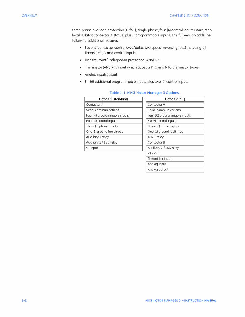
three-phase overload protection (49/51), single-phase, four (4) control inputs (start, stop, local isolator, contactor A status) plus 4 programmable inputs. The full version adds the following additional features:
• Second contactor control (wye/delta, two speed, reversing, etc.) including all timers, relays and control inputs
• Undercurrent/underpower protection (ANSI 37)
• Thermistor (ANSI 49) input which accepts PTC and NTC thermistor types
• Analog input/output
• Six (6) additional programmable inputs plus two (2) control inputs
Table 1–1: MM3 Motor Manager 3 Options
Option 1 (standard) Option 2 (full)
Contactor A Contactor A
Serial communications Serial communications
Four (4) programmable inputs Ten (10) programmable inputs
Four (4) control inputs Six (6) control inputs
Three (3) phase inputs Three (3) phase inputs
One (1) ground fault input One (1) ground fault input
Auxiliary 1 relay Aux 1 relay
Auxiliary 2 / ESD relay Contactor B
VT input Auxiliary 2 / ESD relay
VT input
Thermistor input
Analog input
Analog output
CHAPTER 1: INTRODUCTION OVERVIEW
MM3 MOTOR MANAGER 3 – INSTRUCTION MANUAL 1–3
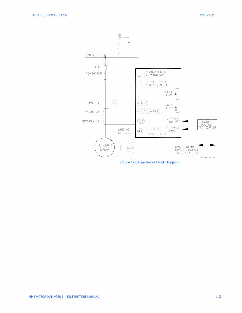
Figure 1-1: Functional block diagram
1–4 MM3 MOTOR MANAGER 3 – INSTRUCTION MANUAL
OVERVIEW CHAPTER 1: INTRODUCTION
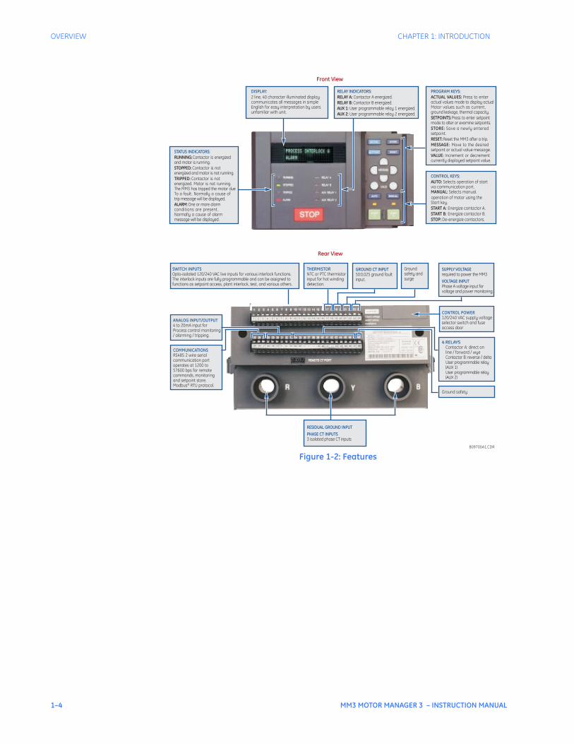
Figure 1-2: Features
10
STATUS INDICATORS:RUNNING:Contactor is energizedand motor is running.STOPPED: Contactor is notenergized and motor is not running.TRIPPED: Contactor is notenergized. Motor is not running.The MM3 has tripped the motor dueTo a fault. Normally a cause oftrip message will be displayed.ALARM: One or more alarmconditions are present .Normally a cause of alarmmessage will be displayed.
Front View
PROGRAM KEYS:ACTUAL VALUES: Press to enteractual values mode to display actualMotor values such as current,ground leakage, thermal capacity.SETPOINTS:Press to enter setpointmode to alter or examine setpoints.STORE: Save a newly enteredsetpoint.RESET:Reset the MM3 after a trip.MESSAGE: Move to the desiredsetpoint or actual value message.VALUE: Increment or decrementcurrently displayed setpoint value.
CONTROL KEYS:AUTO: Selects operation of startvia communication port.MANUAL: Selects manual.operation of motor using theStart key.START A: Energize contactor A.START B: Energize contactor B.STOP: De-energize contactors.
RELAY INDICATORS:RELAY A: Contactor A energized.RELAY B: Contactor B energized.AUX 1: User programmable relay 1 energized.AUX 2: User programmable relay 2 energized.
DISPLAY:2 line, 40 character illuminated displaycommunicates all messages in simpleEnglish for easy interpretation by usersunfamiliar with unit.
GROUND CT INPUT50:0.025 ground faultinput.
Rear View
SUPPLY VOLTAGErequired to power the MM3
VOLTAGE INPUTPhase A voltage input forvoltage and power monitoring.
SWITCH INPUTSOpto-isolated 120/240 VAC live inputs for various interlock functions.The interlock inputs are fully programmable and can be assigned tofunctions as setpoint access, plant interlock, test, and various others.
COMMUNICATIONSRS485 2 wire serialcommunication portoperates at 1200 to57600 bps for remotecommands, monitoringand setpoint store.Modbus® RTU protocol.
Groundsafety andsurge
THERMISTORNTC or PTC thermistorinput for hot windingdetection.
ANALOG INPUT/OUTPUT4 to 20mA input forProcess control monitoring/ alarming / tripping.
4 RELAYSContactor A: direct online / forward / wyeContactor B: reverse / deltaUser programmable relay(AUX 1)User programmable relay(AUX 2)
CONTROL POWER120/240 VAC supply voltageselector switch and fuseaccess door
Ground safety
RESIDUAL GROUND INPUTPHASE CT INPUTS3 isolated phase CT inputs
809700A1.CDR

CHAPTER 1: INTRODUCTION OVERVIEW
MM3 MOTOR MANAGER 3 – INSTRUCTION MANUAL 1–5
1.1.3 Order codes The order codes for the MM3 Motor Manager 3 are shown below.
This instruction manual describes the features of a MM3 Motor Manager 3 with all options included.
Examples:
• MM3 Motor Manager 3–2–E–N–120: full-featured MM3 Motor Manager 3, ESD relay, chassis mount unit with 120 V AC control power
• MM3 Motor Manager 3–1–A–W–240: basic MM3 Motor Manager 3 with auxiliary 2 relay, local display and 240 V AC control power
1.1.4 Accessories The following accessories are available for the MM3 Motor Manager 3:
• EnerVista MM3 Setup software: no-charge software package to aid in setting up MM3 Motor Manager 3 operating parameters (available online at http://www.GEmultilin.com)
• RS-232/485: RS232 to RS485 converter box designed for harsh industrial environments
• 5A Phase CT: 300, 350, 400, 500, 600, 750, 1000
• 50:0.025 ground CT: For sensitive ground detection on high resistance grounded systems
• Control key cover: Covers the auto/manual LEDs, keys and keypad start buttons
Table 1–2: Selection guideMM3
Motor Manag
er 3
– – – –
Base unit MM3 Motor Manag
er 3
| | | | Product family
MM3 Motor Manager 3 options
1 | | | Option 1: basic unit2 | | | Option 2: full unit
Relay E | | ESD relayA | | Auxiliary 2 relay
Display N | No display (chassis unit)W | With local display
Power 120 120 V AC control voltage240 240 V AC control voltage
NOTE
1–6 MM3 MOTOR MANAGER 3 – INSTRUCTION MANUAL
TECHNICAL SPECIFICATIONS CHAPTER 1: INTRODUCTION
1.2 Technical specifications
Design and specifications subject to change without notice.
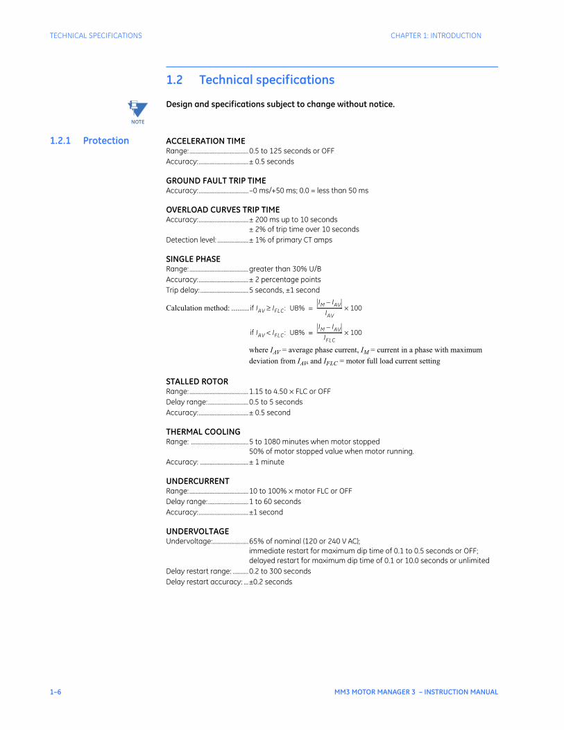
1.2.1 Protection ACCELERATION TIMERange: ......................................0.5 to 125 seconds or OFFAccuracy:................................± 0.5 seconds
GROUND FAULT TRIP TIMEAccuracy:................................–0 ms/+50 ms; 0.0 = less than 50 ms
OVERLOAD CURVES TRIP TIMEAccuracy:................................± 200 ms up to 10 seconds
± 2% of trip time over 10 secondsDetection level: ....................± 1% of primary CT amps
SINGLE PHASERange: ......................................greater than 30% U/BAccuracy:................................± 2 percentage pointsTrip delay:...............................5 seconds, ±1 second
Calculation method: .........
where IAV = average phase current, IM = current in a phase with maximum deviation from IAV, and IFLC = motor full load current setting
STALLED ROTORRange: ......................................1.15 to 4.50 × FLC or OFFDelay range:..........................0.5 to 5 seconds Accuracy:................................± 0.5 second
THERMAL COOLINGRange: .....................................5 to 1080 minutes when motor stopped
50% of motor stopped value when motor running.Accuracy: ...............................± 1 minute
UNDERCURRENTRange: ......................................10 to 100% × motor FLC or OFFDelay range:..........................1 to 60 seconds Accuracy:................................±1 second
UNDERVOLTAGEUndervoltage:.......................65% of nominal (120 or 240 V AC);
immediate restart for maximum dip time of 0.1 to 0.5 seconds or OFF;delayed restart for maximum dip time of 0.1 or 10.0 seconds or unlimited
Delay restart range: ..........0.2 to 300 secondsDelay restart accuracy: ...±0.2 seconds
NOTE
if IAV IFLC≥ : UB%IM IAV–
IAV--------------------- 100×=
if IAV IFLC< : UB%IM IAV–
IFLC--------------------- 100×=
CHAPTER 1: INTRODUCTION TECHNICAL SPECIFICATIONS
MM3 MOTOR MANAGER 3 – INSTRUCTION MANUAL 1–7
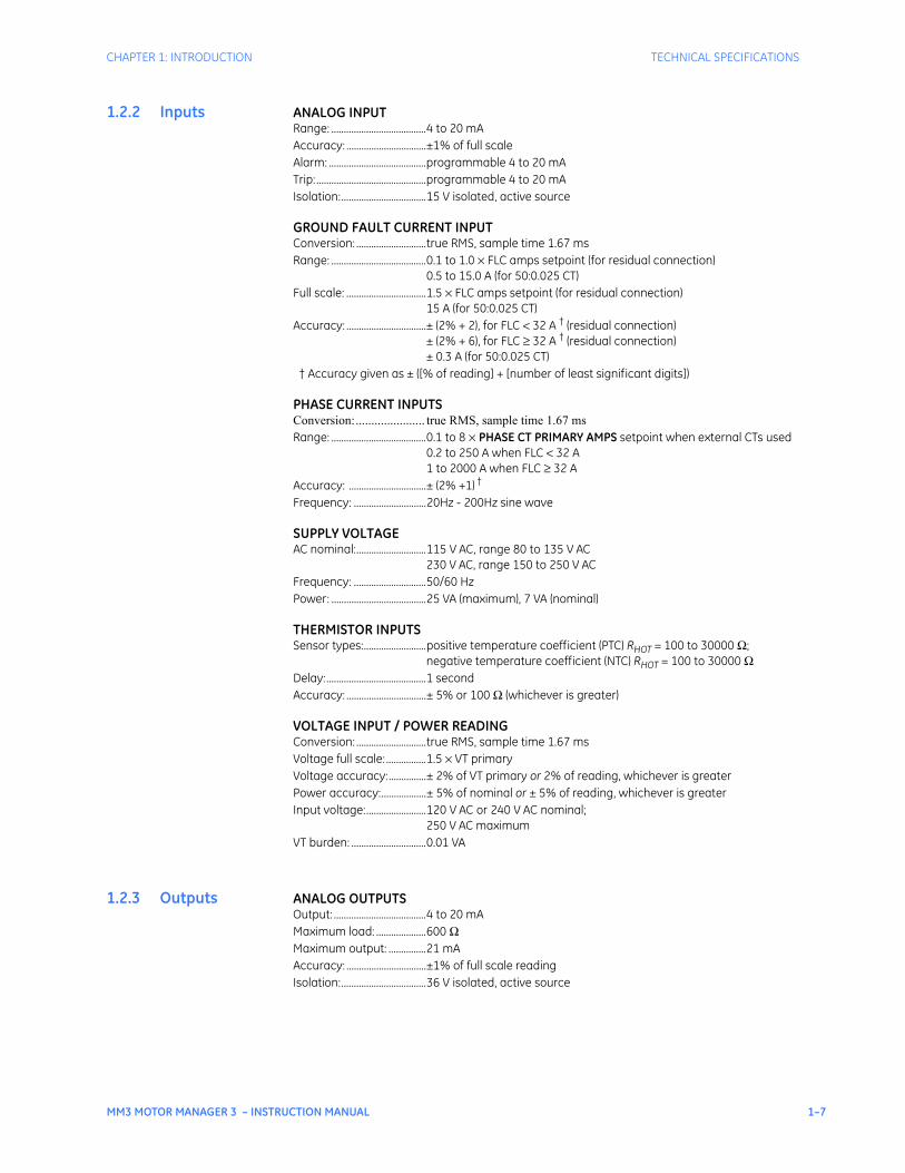
1.2.2 Inputs ANALOG INPUTRange: ......................................4 to 20 mAAccuracy: ................................±1% of full scaleAlarm: .......................................programmable 4 to 20 mATrip: ............................................programmable 4 to 20 mAIsolation:..................................15 V isolated, active source
GROUND FAULT CURRENT INPUTConversion: ............................true RMS, sample time 1.67 msRange: ......................................0.1 to 1.0 × FLC amps setpoint (for residual connection)
0.5 to 15.0 A (for 50:0.025 CT)Full scale: ................................1.5 × FLC amps setpoint (for residual connection)
15 A (for 50:0.025 CT)Accuracy: ................................± (2% + 2), for FLC < 32 A † (residual connection)
± (2% + 6), for FLC ≥ 32 A † (residual connection)± 0.3 A (for 50:0.025 CT)
† Accuracy given as ± ([% of reading] + [number of least significant digits])
PHASE CURRENT INPUTSConversion:...................... true RMS, sample time 1.67 msRange: ......................................0.1 to 8 × PHASE CT PRIMARY AMPS setpoint when external CTs used
0.2 to 250 A when FLC < 32 A1 to 2000 A when FLC ≥ 32 A
Accuracy: ...............................± (2% +1) †
Frequency: .............................20Hz - 200Hz sine wave
SUPPLY VOLTAGEAC nominal:............................115 V AC, range 80 to 135 V AC
230 V AC, range 150 to 250 V ACFrequency: .............................50/60 HzPower: ......................................25 VA (maximum), 7 VA (nominal)
THERMISTOR INPUTSSensor types:.........................positive temperature coefficient (PTC) RHOT = 100 to 30000 Ω;
negative temperature coefficient (NTC) RHOT = 100 to 30000 ΩDelay:........................................1 secondAccuracy: ................................± 5% or 100 Ω (whichever is greater)
VOLTAGE INPUT / POWER READINGConversion: ............................true RMS, sample time 1.67 msVoltage full scale: ................1.5 × VT primaryVoltage accuracy:...............± 2% of VT primary or 2% of reading, whichever is greaterPower accuracy:..................± 5% of nominal or ± 5% of reading, whichever is greaterInput voltage:........................120 V AC or 240 V AC nominal;
250 V AC maximumVT burden: ..............................0.01 VA
1.2.3 Outputs ANALOG OUTPUTSOutput: .....................................4 to 20 mAMaximum load: ....................600 ΩMaximum output: ...............21 mAAccuracy: ................................±1% of full scale readingIsolation:..................................36 V isolated, active source
1–8 MM3 MOTOR MANAGER 3 – INSTRUCTION MANUAL
TECHNICAL SPECIFICATIONS CHAPTER 1: INTRODUCTION
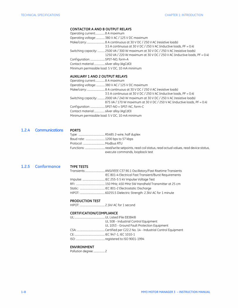
CONTACTOR A AND B OUTPUT RELAYSOperating current:..............8 A maximumOperating voltage: .............380 V AC / 125 V DC maximumMake/carry: ...........................8 A continuous at 30 V DC / 250 V AC (resistive loads)
3.5 A continuous at 30 V DC / 250 V AC (inductive loads, PF = 0.4)Switching capacity: ...........2500 VA / 300 W maximum at 30 V DC / 250 V AC (resistive loads)
1250 VA / 220 W maximum at 30 V DC / 250 V AC (inductive loads, PF = 0.4)Configuration: ......................SPST-NO, form-AContact material:................silver alloy (AgCdO)Minimum permissible load: 5 V DC, 10 mA minimum
AUXILIARY 1 AND 2 OUTPUT RELAYSOperating current:..............8 A maximumOperating voltage: .............380 V AC / 125 V DC maximumMake/carry: ...........................8 A continuous at 30 V DC / 250 V AC (resistive loads)
3.5 A continuous at 30 V DC / 250 V AC (inductive loads, PF = 0.4)Switching capacity: ...........2000 VA / 240 W maximum at 30 V DC / 250 V AC (resistive loads)
875 VA / 170 W maximum at 30 V DC / 250 V AC (inductive loads, PF = 0.4)Configuration: ......................SPST-NO + SPST-NC, form-CContact material:................silver alloy (AgCdO)Minimum permissible load: 5 V DC, 10 mA minimum
1.2.4 Communications PORTSType: ........................................RS485 2-wire, half duplexBaud rate: .............................1200 bps to 57 kbpsProtocol: .................................Modbus RTUFunctions: .............................. read/write setpoints, read coil status, read actual values, read device status,
execute commands, loopback test
1.2.5 Conformance TYPE TESTSTransients:..............................ANSI/IEEE C37.90.1 Oscillatory/Fast Risetime Transients
IEC 801-4 Electrical Fast Transient/Burst RequirementsImpulse: .................................. IEC 255-5 5 kV Impulse Voltage TestRFI: ............................................150 MHz, 450 MHz 5W Handheld Transmitter at 25 cmStatic: ...................................... IEC 801-2 Electrostatic DischargeHIPOT: ......................................60255.5 Dielectric Strength: 2.3kV AC for 1 minute
PRODUCTION TESTHIPOT: ......................................2.1kV AC for 1 second
CERTIFICATION/COMPLIANCEUL:..............................................UL Listed (File E83849)
UL 508 - Industrial Control EquipmentUL 1053 - Ground Fault Protection Equipment
CSA: ...........................................Certified per C22.2 No. 14 - Industrial Control Equipment CE: .............................................. IEC 947-1, IEC 1010-1ISO: ............................................ registered to ISO 9001-1994
ENVIRONMENTPollution degree: .................2
CHAPTER 1: INTRODUCTION TECHNICAL SPECIFICATIONS
MM3 MOTOR MANAGER 3 – INSTRUCTION MANUAL 1–9
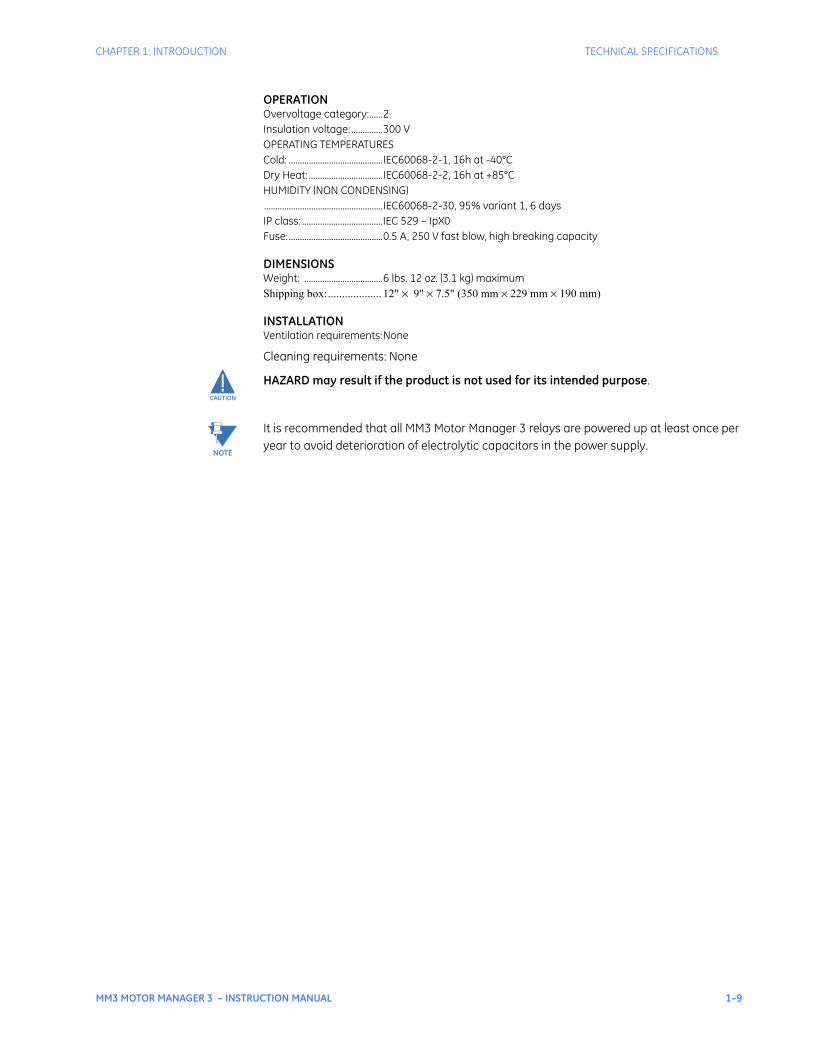
OPERATIONOvervoltage category:......2Insulation voltage: ..............300 VOPERATING TEMPERATURES Cold: ..........................................IEC60068-2-1, 16h at -40°C Dry Heat: .................................IEC60068-2-2, 16h at +85°C HUMIDITY (NON CONDENSING) .....................................................IEC60068-2-30, 95% variant 1, 6 days IP class: ....................................IEC 529 – IpX0Fuse:..........................................0.5 A, 250 V fast blow, high breaking capacity
DIMENSIONSWeight: ...................................6 lbs. 12 oz. (3.1 kg) maximumShipping box:................... 12" × 9" × 7.5" (350 mm × 229 mm × 190 mm)
INSTALLATIONVentilation requirements:None
Cleaning requirements: None
HAZARD may result if the product is not used for its intended purpose.
It is recommended that all MM3 Motor Manager 3 relays are powered up at least once per year to avoid deterioration of electrolytic capacitors in the power supply.
CAUTION
NOTE

1–10 MM3 MOTOR MANAGER 3 – INSTRUCTION MANUAL
TECHNICAL SPECIFICATIONS CHAPTER 1: INTRODUCTION
MM3 MOTOR MANAGER 3 – INSTRUCTION MANUAL 2–1
MM3 Motor Manager 3
Chapter 2: Installation
GE Consumer & IndustrialMultilin
STOP
RUNNING RELAY ARELAY A
STOPPED RELAY BRELAY B
TRIPPED AUX RELAY 1AUX RELAY 1
ALARM AUX RELAY 2AUX RELAY 2
VALUE
MESSAGE
AUTO MANUAL
STORE
RESET
ACTUAL
SETPOINT
START
A
START
A
START
B
START
B
Installation
2.1 Mounting
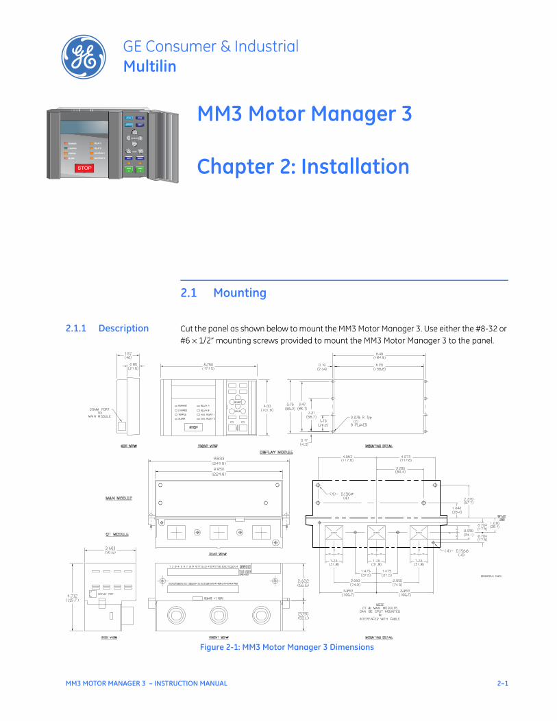
2.1.1 Description Cut the panel as shown below to mount the MM3 Motor Manager 3. Use either the #8-32 or #6 × 1/2” mounting screws provided to mount the MM3 Motor Manager 3 to the panel.
Figure 2-1: MM3 Motor Manager 3 Dimensions
2–2 MM3 MOTOR MANAGER 3 – INSTRUCTION MANUAL
WIRING CHAPTER 2: INSTALLATION
2.2 Wiring
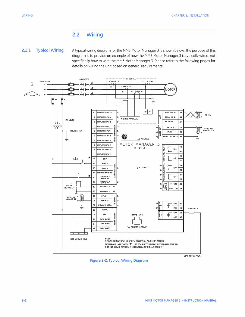
2.2.1 Typical Wiring A typical wiring diagram for the MM3 Motor Manager 3 is shown below. The purpose of this diagram is to provide an example of how the MM3 Motor Manager 3 is typically wired, not specifically how to wire the MM3 Motor Manager 3. Please refer to the following pages for details on wiring the unit based on general requirements.
Figure 2-2: Typical Wiring Diagram
CHAPTER 2: INSTALLATION INPUTS AND OUTPUTS
MM3 MOTOR MANAGER 3 – INSTRUCTION MANUAL 2–3
2.3 Inputs and Outputs
2.3.1 Phase CT Inputs
For motor full-load currents up to 250 A, the phase conductors can be directly connected to the MM3 Motor Manager 3 without phase CTs. If external CTs are required, the secondary winding should be looped though the MM3 Motor Manager 3 doughnut opening.
Selected CTs should be capable of supplying the required current to the total secondary load which consists of the connection wiring burden. The CT must not saturate under maximum current conditions which can be up to 8 times motor full load during starting.
2.3.2 Ground Fault CT Input
The ground fault detection consists of a 50:0.025 input (terminal 19) and a common input (terminal 20), or residual connection of phase CTs (only the common input should be externally grounded). Residual ground fault protection provides a sensitivity of 10% of motor full load current. The 50:0.025 core balance (zero-sequence) CT input can be used for improved sensitivity when measuring the ground fault current.
Care must be taken when enabling the ground fault trip feature. If the interrupting device (contactor or circuit breaker) is not rated to break ground fault current (low resistance or solidly grounded systems), the feature should be disabled. The 50:0.025 input is only recommended to be used on resistance grounded systems.
2.3.3 Supply Voltage A supply voltage of 120/240 V AC at 50/60 Hz is required to power the MM3 Motor Manager 3. The label on the back of the unit specifies the voltage that has been internally set. To change the voltage setting, open the sliding door on the back of the MM3 Motor Manager 3 and locate the supply voltage selector slide switch. The selector slide switch has a label affixed to show the 120/240 V AC positions. Set the slide switch to the desired voltage.
2.3.4 Ground Surge This is an additional ground terminal provided for dissipating transient signals and surges. This must be connected by a thick wire or braid to the system ground for reliable operation.
2.3.5 External Connections
Signal wiring is to box terminals that can accommodate wire as large as 12 gauge. Consult Figure 2-2: Typical Wiring Diagram on page 2–2. Other features can be wired as required.
2.3.6 Thermistor Input
Either a positive temperature coefficient (PTC) or negative temperature coefficient (NTC) thermistor may be directly connected to the MM3 Motor Manager 3. By specifying the hot and cold thermistor resistance, the MM3 Motor Manager 3 automatically determines the thermistor type as NTC or PTC. Use thermistors with hot and cold resistance values in the range 100 to 30000 Ω. If no thermistor is connected, the S1 CONFIGURATION THERMISTOR THERMISTOR TRIP and S1 CONFIGURATION THERMISTOR THERMISTOR ALARM setpoints must be set to “Disable”.
NOTE

2–4 MM3 MOTOR MANAGER 3 – INSTRUCTION MANUAL
INPUTS AND OUTPUTS CHAPTER 2: INSTALLATION
2.3.7 Analog Input The MM3 Motor Manager 3 accepts an analog input from a standard 4 to 20 mA source. This input can be used for process control monitoring to provide status and/or alarm and tripping signals related to the input signal level. The analog input messages (S3 PROCESS
ANALOG INPUT setpoints page) can be programmed to show user-defined names and units.
2.3.8 Analog Output The MM3 Motor Manager 3 is available with a single analog current output for one parameter. The choice of output is selected with the S3 PROCESS ANALOG OUTPUT ANALOG OUTPUT TYPE setpoint. The analog output current scale is 4 to 20 mA.
2.3.9 Auxiliary 2 Coil The AUX 2 relay can be internally energized by the MM3 Motor Manager 3 or externally energized by applying a +24 V DC signal to these terminals. Correct polarity is required (terminal 35 = +24 V DC, terminal 34 = 0 V DC).
2.3.10 Output Relays There are up to four (4) output relays on the MM3 Motor Manager 3. Contact switching rating for the output relays as well can be found in Technical specifications on page 1–6.
• Contactor A relay (terminals 46 and 47): non-reversing, forward, low speed, etc.
• Contactor B relay (terminals 44 and 45): reversing, high speed, etc.
• AUX 1 relay (terminals 40 to 43): field programmable
• AUX 2 relay (terminals 36 to 39): field programmable or hard-wired 24 V DC coil
2.3.11 Serial Commu-nication Port
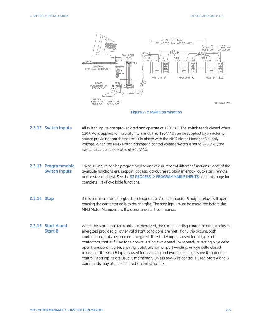
A serial port provides communication capabilities to the MM3 Motor Manager 3. Multiple MM3 Motor Manager 3 relays can be connected together with a 24 AWG stranded, shielded twisted-pair with a characteristic impedance of 120 Ω such as Belden 9841 or equivalent. The total length of communications wiring should not exceed 4000 feet. Care should be used when routing the communications wiring to avoid power AC lines and other sources of electrical noise.
Correct polarity is essential for the communications port to operate. Terminal 25 (“+”) of every MM3 Motor Manager 3 in a serial communication link must be connected together. Similarly, terminal 26 (“–”) of every MM3 Motor Manager 3 must also be connected together. The shield wire must be connected to terminal 27 (485 serial ground) on every unit in the link to provide a common ground potential for all units. Each relay should be daisy-chained to the next one. Avoid star or stub connected configurations if possible to avoid potential communication problems.
A terminating resistor and capacitor network is required to prevent communication errors. Only the last MM3 Motor Manager 3 and the master computer driver should have the terminating network to ensure proper matching. Using terminating resistors and capacitors on all the MM3 Motor Manager 3s would load down the communication network while omitting them at the ends could cause reflections resulting in communication errors.
CHAPTER 2: INSTALLATION INPUTS AND OUTPUTS
MM3 MOTOR MANAGER 3 – INSTRUCTION MANUAL 2–5
Figure 2-3: RS485 termination
2.3.12 Switch Inputs All switch inputs are opto-isolated and operate at 120 V AC. The switch reads closed when 120 V AC is applied to the switch terminal. This 120 V AC can be supplied by an external source providing that the source is in phase with the MM3 Motor Manager 3 supply voltage. When the MM3 Motor Manager 3 control voltage switch is set to 240 V AC, the switch circuit also operates at 240 V AC.
2.3.13 Programmable Switch Inputs
These 10 inputs can be programmed to one of a number of different functions. Some of the available functions are: setpoint access, lockout reset, plant interlock, auto start, remote permissive, and test. See the S3 PROCESS PROGRAMMABLE INPUTS setpoints page for complete list of available functions.
2.3.14 Stop If this terminal is de-energized, both contactor A and contactor B output relays will open causing the contactor coils to de-energize. The stop input must be energized before the MM3 Motor Manager 3 will process any start commands.
2.3.15 Start A and Start B
When the start input terminals are energized, the corresponding contactor output relay is energized provided all other valid start conditions are met. If any trip occurs, both contactor outputs become de-energized. The start A input is used for all types of contactors, that is: full voltage non-reversing, two-speed (low-speed), reversing, wye delta open transition, inverter, slip ring, autotransformer, part winding, or wye delta closed transition. The start B input is used for reversing and two-speed (high-speed) contactor control. Start inputs are usually momentary unless two-wire control is used. Start A and B commands may also be initiated via the serial link.

2–6 MM3 MOTOR MANAGER 3 – INSTRUCTION MANUAL
INPUTS AND OUTPUTS CHAPTER 2: INSTALLATION
2.3.16 Local Isolator NO
The local isolator NO auxiliary contacts are used to prevent motor starts in the event of the local isolator being in the “open” position. To prevent starts, the MM3 Motor Manager 3 produces a trip when the local isolator input is open. A local isolator trip is automatically reset when the local isolator is reclosed.
The local isolator input can be enabled or disabled as required. The factory default is disabled.
2.3.17 Contactor Status
The MM3 Motor Manager 3 must know the state of the contactor at all times in order to detect discrepancies in contactor close/open commands and also to display the state of the contactor. There are two contactor status inputs on the MM3 Motor Manager 3, one for contactor A, the other for contactor B.
Auxiliary contacts mechanically linked to the contactor itself are used to feed back to the contactor status inputs. No status change following a start command indicates an open contactor control circuit and no status change following stop command indicates a welded contactor. Appropriate messages and alarms are displayed for these conditions and the status can be read via the serial port.
If the motor contactor is externally energized, the MM3 Motor Manager 3 will seal in the output relay and display an “EXTERNAL START” message. If the motor contactor is externally de-energized, the MM3 Motor Manager 3 will drop out the output relay and display an “EXTERNAL STOP” message.
2.3.18 Dielectric Strength Testing
It may be required to test a complete MCC with MM3 Motor Manager 3s installed for dielectric strength. This is also known as “flash” or “hipot” testing. The MM3 Motor Manager 3 is rated for 1800 V AC for 1 minute or 2200 V AC for 1 second isolation between switch inputs, relay outputs, VT voltage input, supply voltage inputs and ground terminals 21 and 48.
When performing dielectric tests, the connection to the surge ground terminal (22) must be removed. A filter network is used on the AC input to filter out RF and EMI noise. The filter capacitors and transient absorbers could be damaged by the high voltages relative to surge ground on the AC input.
Under no circumstances should any inputs other than switches, relays, supply voltage, and VT input be dielectric tested.
CAUTION
CHAPTER 2: INSTALLATION STARTER TYPES
MM3 MOTOR MANAGER 3 – INSTRUCTION MANUAL 2–7
2.4 Starter Types
2.4.1 Full-voltage Non-reversing Starter
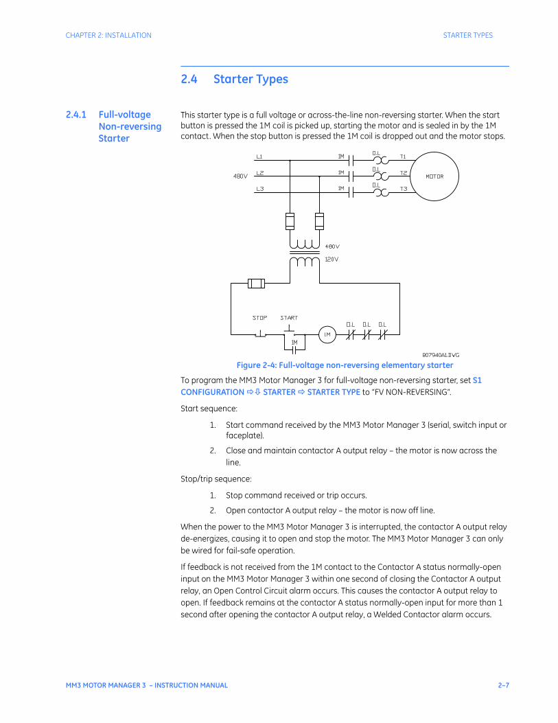
This starter type is a full voltage or across-the-line non-reversing starter. When the start button is pressed the 1M coil is picked up, starting the motor and is sealed in by the 1M contact. When the stop button is pressed the 1M coil is dropped out and the motor stops.
Figure 2-4: Full-voltage non-reversing elementary starter
To program the MM3 Motor Manager 3 for full-voltage non-reversing starter, set S1 CONFIGURATION STARTER STARTER TYPE to “FV NON-REVERSING”.
Start sequence:
1. Start command received by the MM3 Motor Manager 3 (serial, switch input or faceplate).
2. Close and maintain contactor A output relay – the motor is now across the line.
Stop/trip sequence:
1. Stop command received or trip occurs.
2. Open contactor A output relay – the motor is now off line.
When the power to the MM3 Motor Manager 3 is interrupted, the contactor A output relay de-energizes, causing it to open and stop the motor. The MM3 Motor Manager 3 can only be wired for fail-safe operation.
If feedback is not received from the 1M contact to the Contactor A status normally-open input on the MM3 Motor Manager 3 within one second of closing the Contactor A output relay, an Open Control Circuit alarm occurs. This causes the contactor A output relay to open. If feedback remains at the contactor A status normally-open input for more than 1 second after opening the contactor A output relay, a Welded Contactor alarm occurs.
2–8 MM3 MOTOR MANAGER 3 – INSTRUCTION MANUAL
STARTER TYPES CHAPTER 2: INSTALLATION
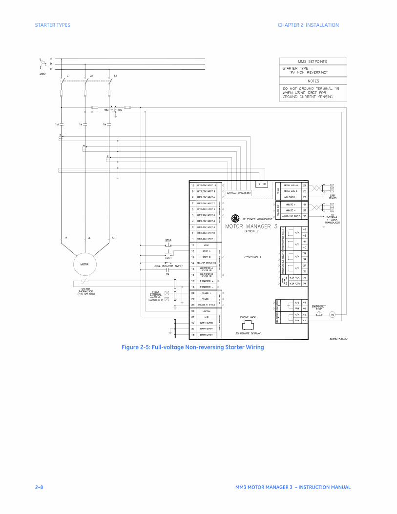
Figure 2-5: Full-voltage Non-reversing Starter Wiring
CHAPTER 2: INSTALLATION STARTER TYPES
MM3 MOTOR MANAGER 3 – INSTRUCTION MANUAL 2–9
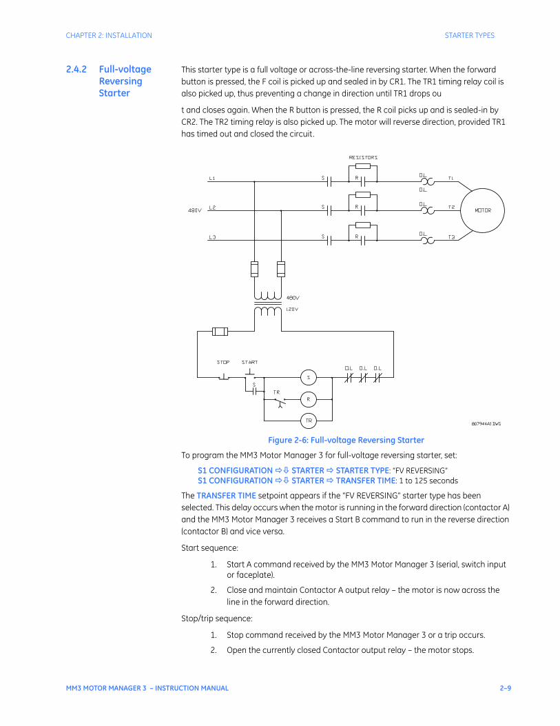
2.4.2 Full-voltage Reversing Starter
This starter type is a full voltage or across-the-line reversing starter. When the forward button is pressed, the F coil is picked up and sealed in by CR1. The TR1 timing relay coil is also picked up, thus preventing a change in direction until TR1 drops ou
t and closes again. When the R button is pressed, the R coil picks up and is sealed-in by CR2. The TR2 timing relay is also picked up. The motor will reverse direction, provided TR1 has timed out and closed the circuit.
Figure 2-6: Full-voltage Reversing Starter
To program the MM3 Motor Manager 3 for full-voltage reversing starter, set:
S1 CONFIGURATION STARTER STARTER TYPE: “FV REVERSING”S1 CONFIGURATION STARTER TRANSFER TIME: 1 to 125 seconds
The TRANSFER TIME setpoint appears if the “FV REVERSING” starter type has been selected. This delay occurs when the motor is running in the forward direction (contactor A) and the MM3 Motor Manager 3 receives a Start B command to run in the reverse direction (contactor B) and vice versa.
Start sequence:
1. Start A command received by the MM3 Motor Manager 3 (serial, switch input or faceplate).
2. Close and maintain Contactor A output relay – the motor is now across the line in the forward direction.
Stop/trip sequence:
1. Stop command received by the MM3 Motor Manager 3 or a trip occurs.
2. Open the currently closed Contactor output relay – the motor stops.
2–10 MM3 MOTOR MANAGER 3 – INSTRUCTION MANUAL
STARTER TYPES CHAPTER 2: INSTALLATION
Reverse (if the motor is running in the forward direction) sequence:
1. Start B command is received by the MM3 Motor Manager 3 (serial, switch input or faceplate).
2. Open Contactor A relay – the motor is now off line
3. Wait the required transfer time.
4. Close and maintain Contactor B output relay – the motor is now across the line in the reverse direction.
All output relays de-energize when the MM3 Motor Manager 3 power is interrupted, causing them to open and stop the motor. The MM3 Motor Manager 3 can only be wired for fail-safe operation.
If used, the VT input must have a separate PT so that the current and voltage inputs remain in phase regardless of which direction the motor is running. See the following figure.
If feedback is not received from either the F or the R contactor to Contactor Status N.O. inputs within one second of closing Contactor A or B output relays, an OPEN CONTROL CIRCUIT alarm will occur. This will cause the currently closed relay to open.
If feedback remains at the Contactor (A or B) Status N.O. input more than one second after opening Contactor A or B output relays, a WELDED CONTACTOR alarm will occur.
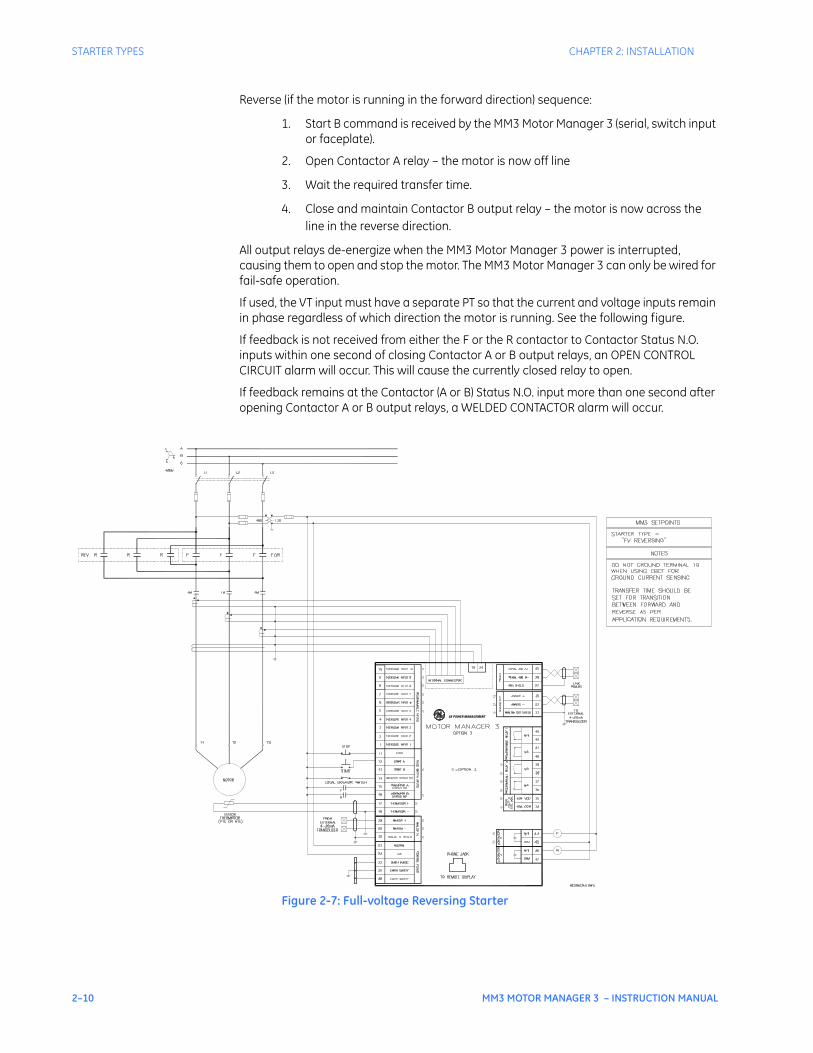
Figure 2-7: Full-voltage Reversing Starter
GE POWER MANAGEMENT
CHAPTER 2: INSTALLATION STARTER TYPES
MM3 MOTOR MANAGER 3 – INSTRUCTION MANUAL 2–11
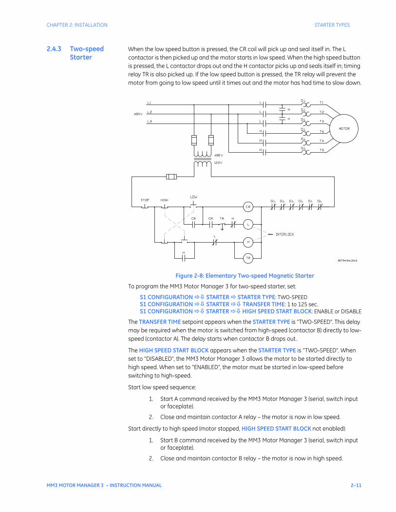
2.4.3 Two-speed Starter
When the low speed button is pressed, the CR coil will pick up and seal itself in. The L contactor is then picked up and the motor starts in low speed. When the high speed button is pressed, the L contactor drops out and the H contactor picks up and seals itself in; timing relay TR is also picked up. If the low speed button is pressed, the TR relay will prevent the motor from going to low speed until it times out and the motor has had time to slow down.
Figure 2-8: Elementary Two-speed Magnetic Starter
To program the MM3 Motor Manager 3 for two-speed starter, set:
S1 CONFIGURATION STARTER STARTER TYPE: TWO-SPEEDS1 CONFIGURATION STARTER TRANSFER TIME: 1 to 125 sec.S1 CONFIGURATION STARTER HIGH SPEED START BLOCK: ENABLE or DISABLE
The TRANSFER TIME setpoint appears when the STARTER TYPE is “TWO-SPEED”. This delay may be required when the motor is switched from high-speed (contactor B) directly to low-speed (contactor A). The delay starts when contactor B drops out.
The HIGH SPEED START BLOCK appears when the STARTER TYPE is “TWO-SPEED”. When set to “DISABLED”, the MM3 Motor Manager 3 allows the motor to be started directly to high speed. When set to “ENABLED”, the motor must be started in low-speed before switching to high-speed.
Start low speed sequence:
1. Start A command received by the MM3 Motor Manager 3 (serial, switch input or faceplate).
2. Close and maintain contactor A relay – the motor is now in low speed.
Start directly to high speed (motor stopped, HIGH SPEED START BLOCK not enabled):
1. Start B command received by the MM3 Motor Manager 3 (serial, switch input or faceplate).
2. Close and maintain contactor B relay – the motor is now in high speed.
2–12 MM3 MOTOR MANAGER 3 – INSTRUCTION MANUAL
STARTER TYPES CHAPTER 2: INSTALLATION
Start directly to high speed (motor stopped, HIGH SPEED START BLOCK enabled) sequence:
1. Start B command received by the MM3 Motor Manager 3 (serial, switch input or faceplate).
2. No response to start B commands.
Low to high speed transition sequence:
1. Start B command is received (serial, switch input or faceplate).
2. Open contactor A output relay.
3. Close and maintain Contactor B relay – the motor is now in high speed.
High to low speed transition sequence:
1. Start A command is received (serial, switch input or faceplate).
2. Open contactor B output relay.
3. Wait for the programmed transfer time.
4. Close and maintain contactor A.
Stop/trip sequence:
1. Stop command received by the MM3 Motor Manager 3 or a trip occurs.
2. Open the currently closed contactor output relay.
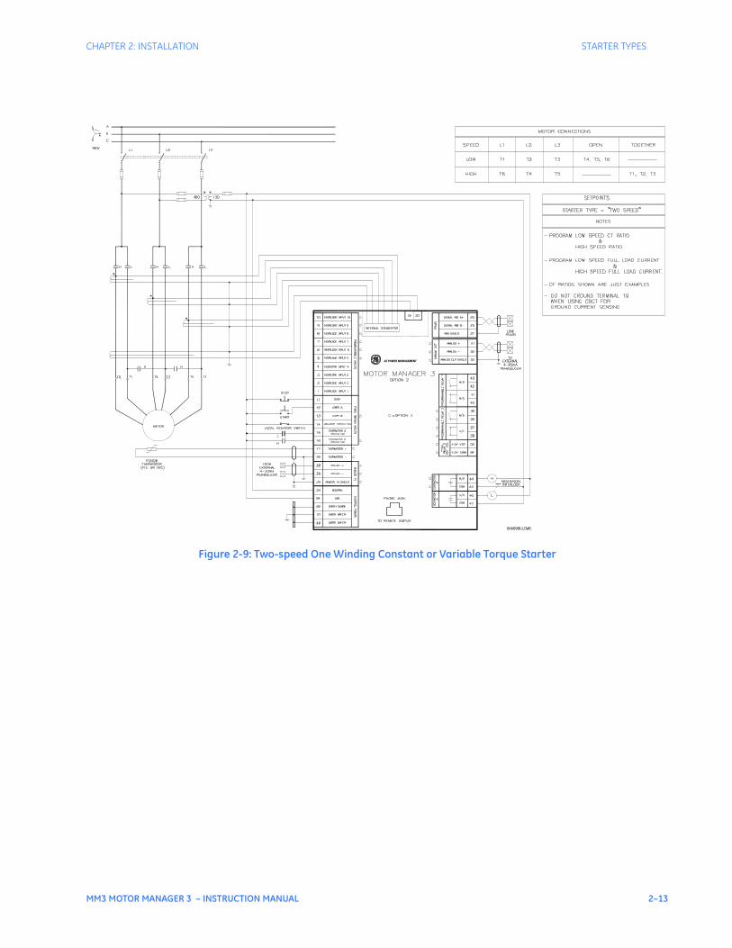
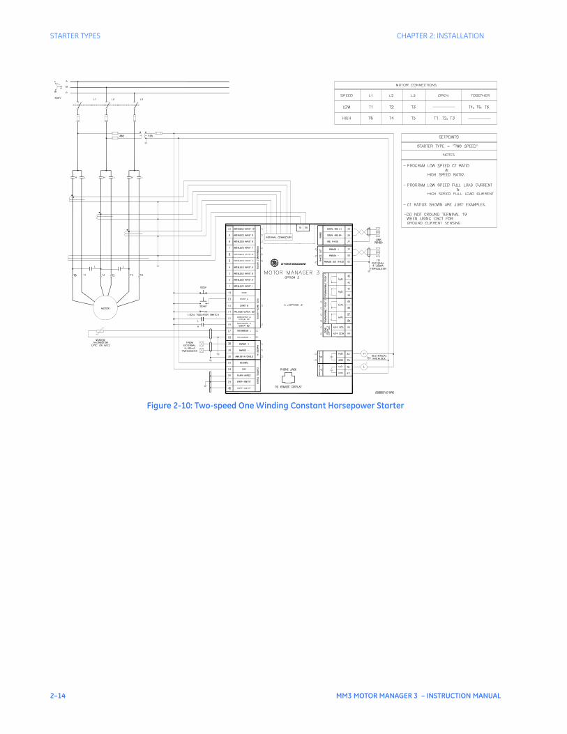
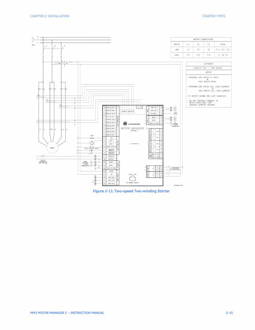
There are many different configurations for the TWO SPEED starter type. Three of the more popular ones are illustrated here: two-speed one winding constant or variable torque, two-speed one winding constant horsepower, and two-speed two winding.
When the power to the MM3 Motor Manager 3 is interrupted, all MM3 Motor Manager 3 output relays de-energize, causing them to open and stop the motor. The MM3 Motor Manager 3 can only be wired for fail-safe operation.
If feedback is not received from the L or H contacts to the Contactor A or B Status N.O. input within one second of closing Contactor A relay, an OPEN CONTROL CIRCUIT alarm will occur. This will cause Contactor A and B output relays to open.
If feedback remains at the Contactor A or B Status N.O. input more than one second after opening the Contactor A or B output relays, a WELDED CONTACTOR alarm will occur.
CHAPTER 2: INSTALLATION STARTER TYPES
MM3 MOTOR MANAGER 3 – INSTRUCTION MANUAL 2–13
Figure 2-9: Two-speed One Winding Constant or Variable Torque Starter
GE POWER MANAGEMENT
2–14 MM3 MOTOR MANAGER 3 – INSTRUCTION MANUAL
STARTER TYPES CHAPTER 2: INSTALLATION
Figure 2-10: Two-speed One Winding Constant Horsepower Starter
GE POWER MANAGEMENT
CHAPTER 2: INSTALLATION STARTER TYPES
MM3 MOTOR MANAGER 3 – INSTRUCTION MANUAL 2–15
Figure 2-11: Two-speed Two-winding Starter
GE POWER MANAGEMENT
2–16 MM3 MOTOR MANAGER 3 – INSTRUCTION MANUAL
STARTER TYPES CHAPTER 2: INSTALLATION
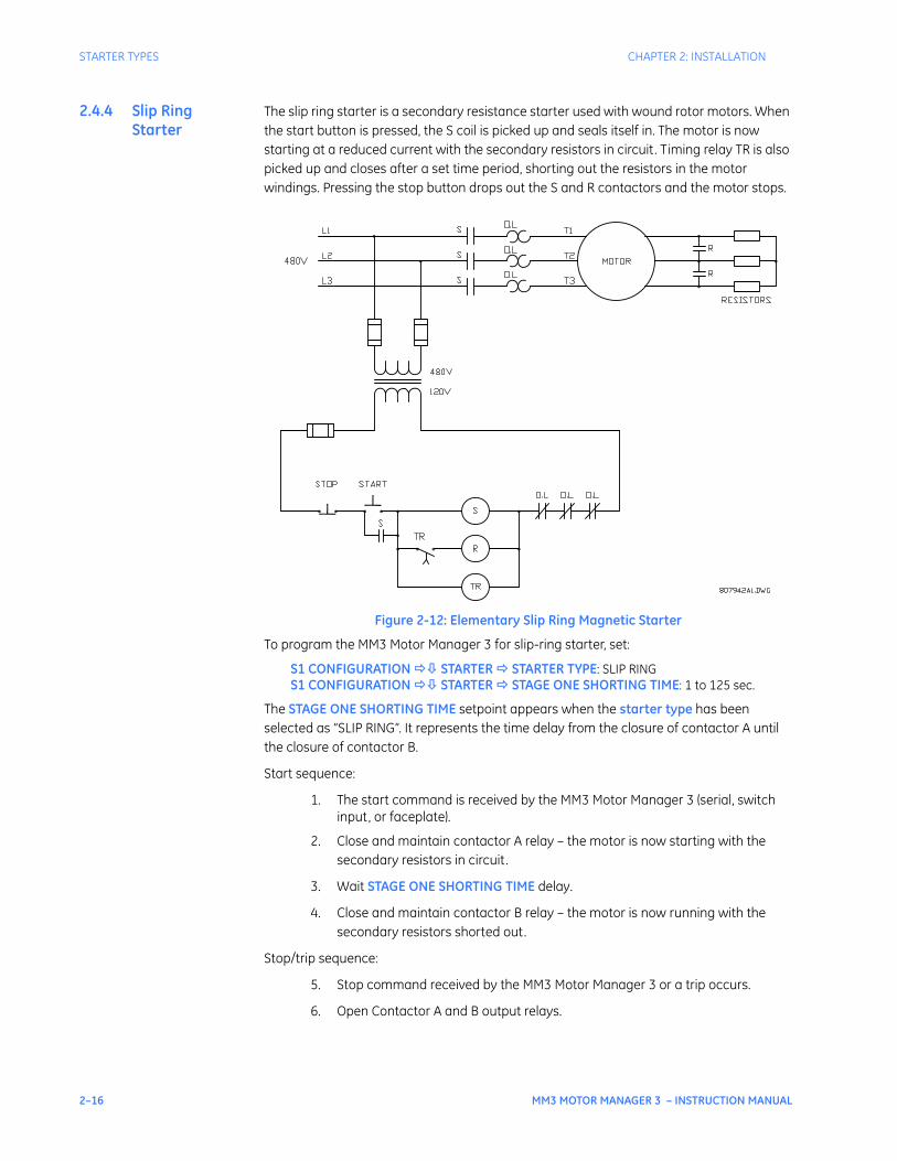
2.4.4 Slip Ring Starter
The slip ring starter is a secondary resistance starter used with wound rotor motors. When the start button is pressed, the S coil is picked up and seals itself in. The motor is now starting at a reduced current with the secondary resistors in circuit. Timing relay TR is also picked up and closes after a set time period, shorting out the resistors in the motor windings. Pressing the stop button drops out the S and R contactors and the motor stops.
Figure 2-12: Elementary Slip Ring Magnetic Starter
To program the MM3 Motor Manager 3 for slip-ring starter, set:
S1 CONFIGURATION STARTER STARTER TYPE: SLIP RINGS1 CONFIGURATION STARTER STAGE ONE SHORTING TIME: 1 to 125 sec.
The STAGE ONE SHORTING TIME setpoint appears when the starter type has been selected as “SLIP RING”. It represents the time delay from the closure of contactor A until the closure of contactor B.
Start sequence:
1. The start command is received by the MM3 Motor Manager 3 (serial, switch input, or faceplate).
2. Close and maintain contactor A relay – the motor is now starting with the secondary resistors in circuit.
3. Wait STAGE ONE SHORTING TIME delay.
4. Close and maintain contactor B relay – the motor is now running with the secondary resistors shorted out.
Stop/trip sequence:
5. Stop command received by the MM3 Motor Manager 3 or a trip occurs.
6. Open Contactor A and B output relays.
CHAPTER 2: INSTALLATION STARTER TYPES
MM3 MOTOR MANAGER 3 – INSTRUCTION MANUAL 2–17
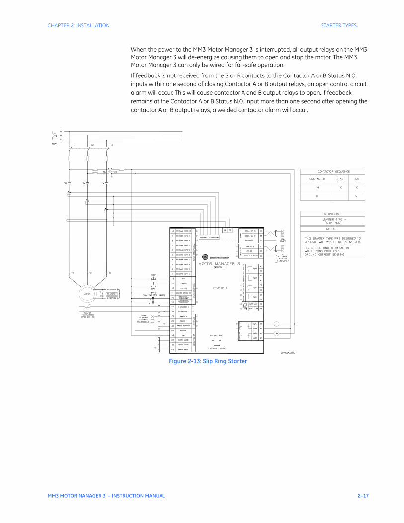
When the power to the MM3 Motor Manager 3 is interrupted, all output relays on the MM3 Motor Manager 3 will de-energize causing them to open and stop the motor. The MM3 Motor Manager 3 can only be wired for fail-safe operation.
If feedback is not received from the S or R contacts to the Contactor A or B Status N.O. inputs within one second of closing Contactor A or B output relays, an open control circuit alarm will occur. This will cause contactor A and B output relays to open. If feedback remains at the Contactor A or B Status N.O. input more than one second after opening the contactor A or B output relays, a welded contactor alarm will occur.
Figure 2-13: Slip Ring Starter
GE POWER MANAGEMENT
2–18 MM3 MOTOR MANAGER 3 – INSTRUCTION MANUAL
STARTER TYPES CHAPTER 2: INSTALLATION
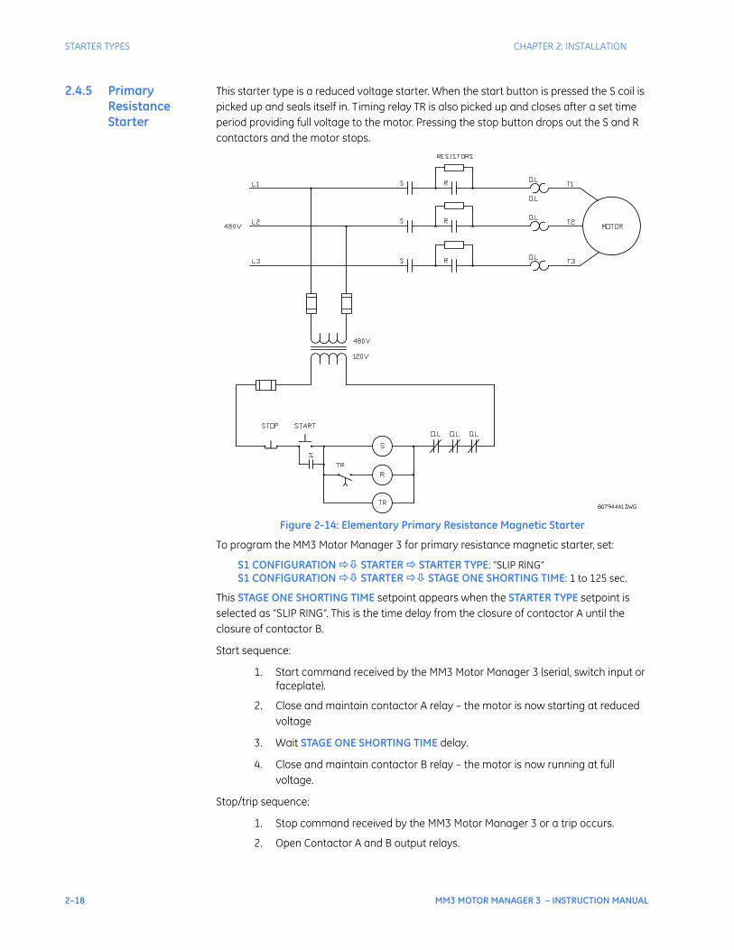
2.4.5 Primary Resistance Starter
This starter type is a reduced voltage starter. When the start button is pressed the S coil is picked up and seals itself in. Timing relay TR is also picked up and closes after a set time period providing full voltage to the motor. Pressing the stop button drops out the S and R contactors and the motor stops.
Figure 2-14: Elementary Primary Resistance Magnetic Starter
To program the MM3 Motor Manager 3 for primary resistance magnetic starter, set:
S1 CONFIGURATION STARTER STARTER TYPE: “SLIP RING”S1 CONFIGURATION STARTER STAGE ONE SHORTING TIME: 1 to 125 sec.
This STAGE ONE SHORTING TIME setpoint appears when the STARTER TYPE setpoint is selected as “SLIP RING”. This is the time delay from the closure of contactor A until the closure of contactor B.
Start sequence:
1. Start command received by the MM3 Motor Manager 3 (serial, switch input or faceplate).
2. Close and maintain contactor A relay – the motor is now starting at reduced voltage
3. Wait STAGE ONE SHORTING TIME delay.
4. Close and maintain contactor B relay – the motor is now running at full voltage.
Stop/trip sequence:
1. Stop command received by the MM3 Motor Manager 3 or a trip occurs.
2. Open Contactor A and B output relays.
CHAPTER 2: INSTALLATION STARTER TYPES
MM3 MOTOR MANAGER 3 – INSTRUCTION MANUAL 2–19
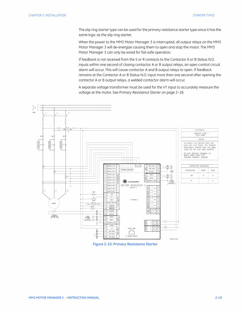
The slip ring starter type can be used for the primary resistance starter type since it has the same logic as the slip ring starter.
When the power to the MM3 Motor Manager 3 is interrupted, all output relays on the MM3 Motor Manager 3 will de-energize causing them to open and stop the motor. The MM3 Motor Manager 3 can only be wired for fail-safe operation.
If feedback is not received from the S or R contacts to the Contactor A or B Status N.O. inputs within one second of closing contactor A or B output relays, an open control circuit alarm will occur. This will cause contactor A and B output relays to open. If feedback remains at the Contactor A or B Status N.O. input more than one second after opening the contactor A or B output relays, a welded contactor alarm will occur.
A separate voltage transformer must be used for the VT input to accurately measure the voltage at the motor. See Primary Resistance Starter on page 2–18.
Figure 2-15: Primary Resistance Starter
GE POWER MANAGEMENT
2–20 MM3 MOTOR MANAGER 3 – INSTRUCTION MANUAL
STARTER TYPES CHAPTER 2: INSTALLATION
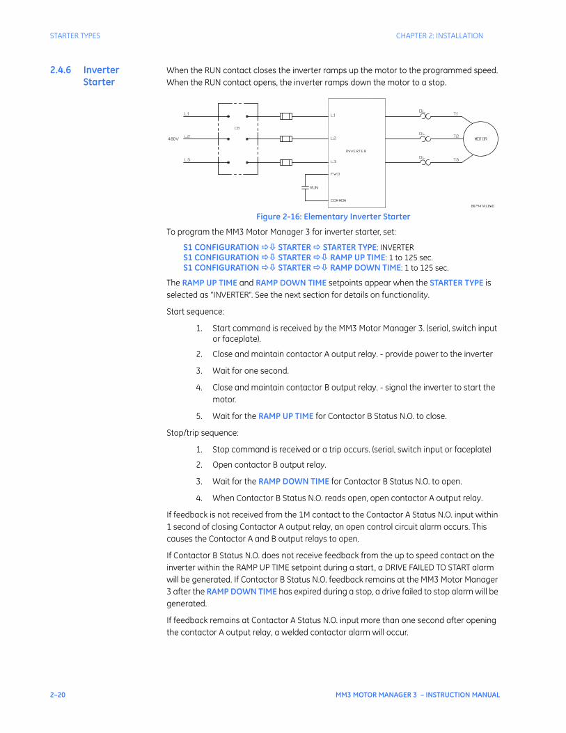
2.4.6 Inverter Starter
When the RUN contact closes the inverter ramps up the motor to the programmed speed. When the RUN contact opens, the inverter ramps down the motor to a stop.
Figure 2-16: Elementary Inverter Starter
To program the MM3 Motor Manager 3 for inverter starter, set:
S1 CONFIGURATION STARTER STARTER TYPE: INVERTERS1 CONFIGURATION STARTER RAMP UP TIME: 1 to 125 sec.S1 CONFIGURATION STARTER RAMP DOWN TIME: 1 to 125 sec.
The RAMP UP TIME and RAMP DOWN TIME setpoints appear when the STARTER TYPE is selected as “INVERTER”. See the next section for details on functionality.
Start sequence:
1. Start command is received by the MM3 Motor Manager 3. (serial, switch input or faceplate).
2. Close and maintain contactor A output relay. - provide power to the inverter
3. Wait for one second.
4. Close and maintain contactor B output relay. - signal the inverter to start the motor.
5. Wait for the RAMP UP TIME for Contactor B Status N.O. to close.
Stop/trip sequence:
1. Stop command is received or a trip occurs. (serial, switch input or faceplate)
2. Open contactor B output relay.
3. Wait for the RAMP DOWN TIME for Contactor B Status N.O. to open.
4. When Contactor B Status N.O. reads open, open contactor A output relay.
If feedback is not received from the 1M contact to the Contactor A Status N.O. input within 1 second of closing Contactor A output relay, an open control circuit alarm occurs. This causes the Contactor A and B output relays to open.
If Contactor B Status N.O. does not receive feedback from the up to speed contact on the inverter within the RAMP UP TIME setpoint during a start, a DRIVE FAILED TO START alarm will be generated. If Contactor B Status N.O. feedback remains at the MM3 Motor Manager 3 after the RAMP DOWN TIME has expired during a stop, a drive failed to stop alarm will be generated.
If feedback remains at Contactor A Status N.O. input more than one second after opening the contactor A output relay, a welded contactor alarm will occur.
CHAPTER 2: INSTALLATION STARTER TYPES
MM3 MOTOR MANAGER 3 – INSTRUCTION MANUAL 2–21
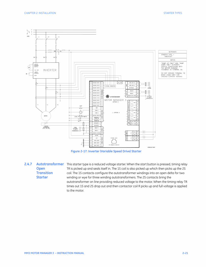
Figure 2-17: Inverter (Variable Speed Drive) Starter
2.4.7 Autotransformer Open Transition Starter
This starter type is a reduced voltage starter. When the start button is pressed, timing relay TR is picked up and seals itself in. The 1S coil is also picked up which then picks up the 2S coil. The 1S contacts configure the autotransformer windings into an open delta for two winding or wye for three winding autotransformers. The 2S contacts bring the autotransformer on line providing reduced voltage to the motor. When the timing relay TR times out 1S and 2S drop out and then contactor coil R picks up and full voltage is applied to the motor.
GE POWER MANAGEMENT
2–22 MM3 MOTOR MANAGER 3 – INSTRUCTION MANUAL
STARTER TYPES CHAPTER 2: INSTALLATION
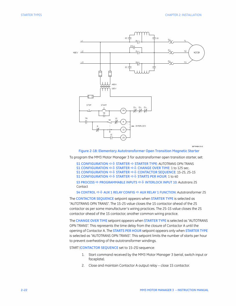
Figure 2-18: Elementary Autotransformer Open Transition Magnetic Starter
To program the MM3 Motor Manager 3 for autotransformer open transition starter, set:
S1 CONFIGURATION STARTER STARTER TYPE: AUTOTRANS OPN TRANSS1 CONFIGURATION STARTER CHANGE OVER TIME: 1 to 125 sec.S1 CONFIGURATION STARTER CONTACTOR SEQUENCE: 1S-2S, 2S-1SS1 CONFIGURATION STARTER STARTS PER HOUR: 1 to 40
S3 PROCESS PROGRAMMABLE INPUTS INTERLOCK INPUT 10: Autotrans 2S Contact
S4 CONTROL AUX 1 RELAY CONFIG AUX RELAY 1 FUNCTION: Autotransformer 2S
The CONTACTOR SEQUENCE setpoint appears when STARTER TYPE is selected as “AUTOTRANS OPN TRANS”. The 1S-2S value closes the 1S contactor ahead of the 2S contactor as per some manufacturer’s wiring practices. The 2S-1S value closes the 2S contactor ahead of the 1S contactor, another common wiring practice.
The CHANGE OVER TIME setpoint appears when STARTER TYPE is selected as “AUTOTRANS OPN TRANS”. This represents the time delay from the closure of Contactor A until the opening of Contactor A. The STARTS PER HOUR setpoint appears only when STARTER TYPE is selected as “AUTOTRANS OPN TRANS”. This setpoint limits the number of starts per hour to prevent overheating of the autotransformer windings.
START (CONTACTOR SEQUENCE set to 1S-2S) sequence:
1. Start command received by the MM3 Motor Manager 3 (serial, switch input or faceplate).
2. Close and maintain Contactor A output relay – close 1S contactor.

CHAPTER 2: INSTALLATION STARTER TYPES
MM3 MOTOR MANAGER 3 – INSTRUCTION MANUAL 2–23
3. Wait 20 ms, close and maintain the auxiliary 1 output relay – power is applied to the autotransformer.
4. Wait for the time set in the CHANGE OVER TIME setpoint.
5. Open contactor A and auxiliary output relays.
6. Wait 20 ms.
7. Close and maintain contactor B output relay.
Start (CONTACTOR SEQUENCE set to 2S-1S) sequence:
1. Start command received by the MM3 Motor Manager 3 (serial, switch input or faceplate).
2. Close and maintain the auxiliary output relay; power is applied to the autotransformer.
3. Wait 20 ms, close and maintain contactor A output relay – close the 1S contactor.
4. Wait for the time set in the CHANGE OVER TIME setpoint.
5. Open contactor A and auxiliary output relays.
6. Wait 20 ms.
7. Close and maintain contactor B output relay.
Stop/trip sequence:
1. Stop command received by the MM3 Motor Manager 3 or a trip occurs.
2. Open contactor B output relay.
If feedback is not received from the 1S, 2S or R contacts to the contactor A, B or auxiliary relay status N.O. inputs within one second of closing contactors A, B or the auxiliary relay, an open control circuit alarm will occur. This opens contactors A, B and the auxiliary relay.
If feedback remains at any of the Status N.O. inputs for more than one second after opening the its respective relay, a welded contactor alarm will occur.
2–24 MM3 MOTOR MANAGER 3 – INSTRUCTION MANUAL
STARTER TYPES CHAPTER 2: INSTALLATION
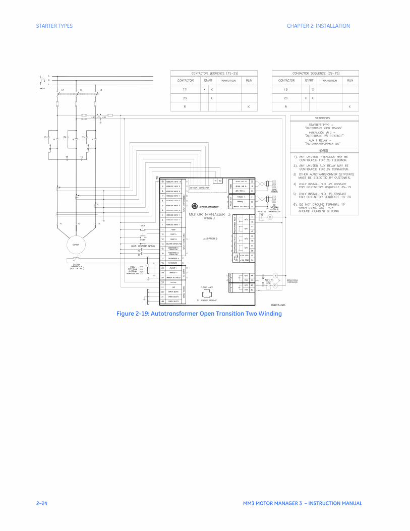
Figure 2-19: Autotransformer Open Transition Two Winding
GE POWER MANAGEMENT
CHAPTER 2: INSTALLATION STARTER TYPES
MM3 MOTOR MANAGER 3 – INSTRUCTION MANUAL 2–25
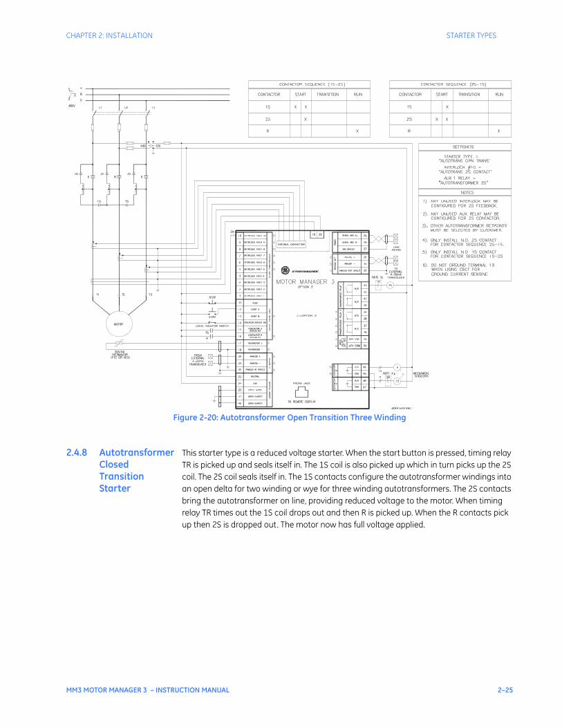
Figure 2-20: Autotransformer Open Transition Three Winding
2.4.8 Autotransformer Closed Transition Starter
This starter type is a reduced voltage starter. When the start button is pressed, timing relay TR is picked up and seals itself in. The 1S coil is also picked up which in turn picks up the 2S coil. The 2S coil seals itself in. The 1S contacts configure the autotransformer windings into an open delta for two winding or wye for three winding autotransformers. The 2S contacts bring the autotransformer on line, providing reduced voltage to the motor. When timing relay TR times out the 1S coil drops out and then R is picked up. When the R contacts pick up then 2S is dropped out. The motor now has full voltage applied.
GE POWER MANAGEMENT
2–26 MM3 MOTOR MANAGER 3 – INSTRUCTION MANUAL
STARTER TYPES CHAPTER 2: INSTALLATION
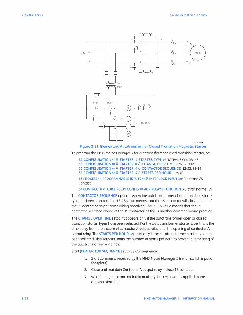
Figure 2-21: Elementary Autotransformer Closed Transition Magnetic Starter
To program the MM3 Motor Manager 3 for autotransformer closed transition starter, set:
S1 CONFIGURATION STARTER STARTER TYPE: AUTOTRANS CLS TRANSS1 CONFIGURATION STARTER CHANGE OVER TIME: 1 to 125 sec.S1 CONFIGURATION STARTER CONTACTOR SEQUENCE: 1S-2S, 2S-1SS1 CONFIGURATION STARTER STARTS PER HOUR: 1 to 40
S3 PROCESS PROGRAMMABLE INPUTS INTERLOCK INPUT 10: Autotrans 2S Contact
S4 CONTROL AUX 1 RELAY CONFIG AUX RELAY 1 FUNCTION: Autotransformer 2S
The CONTACTOR SEQUENCE appears when the autotransformer closed transition starter type has been selected. The 1S-2S value means that the 1S contactor will close ahead of the 2S contactor as per some wiring practices. The 2S-1S value means that the 2S contactor will close ahead of the 1S contactor as this is another common wiring practice.
The CHANGE OVER TIME setpoint appears only if the autotransformer open or closed transition starter types have been selected. For the autotransformer starter type, this is the time delay from the closure of contactor A output relay until the opening of contactor A output relay. The STARTS PER HOUR setpoint only if the autotransformer starter type has been selected. This setpoint limits the number of starts per hour to prevent overheating of the autotransformer windings.
Start (CONTACTOR SEQUENCE set to 1S-2S) sequence:
1. Start command received by the MM3 Motor Manager 3 (serial, switch input or faceplate).
2. Close and maintain Contactor A output relay – close 1S contactor.
3. Wait 20 ms, close and maintain auxiliary 1 relay; power is applied to the autotransformer.

CHAPTER 2: INSTALLATION STARTER TYPES
MM3 MOTOR MANAGER 3 – INSTRUCTION MANUAL 2–27
4. Wait for the time set in the CHANGE OVER TIME setpoint.
5. Open contactor A output relay and wait 20 ms.
6. Close and maintain Contactor B output relay.
7. Wait 40 ms.
8. Open Aux. 1 output relay.
Start (CONTACTOR SEQUENCE set to 2S-1S) sequence:
1. Start command received by the MM3 Motor Manager 3 (serial, switch input or faceplate).
2. Close and maintain auxiliary 1 output relay – power is applied to the autotransformer.
3. Wait 40 ms, close and maintain contactor A relay – close the 1S contactor.
4. Wait for the time set in the CHANGE OVER TIME setpoint.
5. Open contactor A output relay and wait 20 ms.
6. Close and maintain contactor B output relay.
7. Wait 40 ms, then open auxiliary 1 output relay.
Stop/trip sequence:
1. Stop command received by the MM3 Motor Manager 3 or a trip occurs.
2. Open contactor B output relay.
If feedback is not received by the contactor A, B or auxiliary relay status N.O. inputs within one second of closing contactors A, B or the auxiliary output relays, an open control circuit alarm will occur. This will cause contactors A, B and the auxiliary relay to open.
If feedback remains at any of the status N.O. inputs for more than one second after opening its respective relay, a welded contactor alarm will occur.
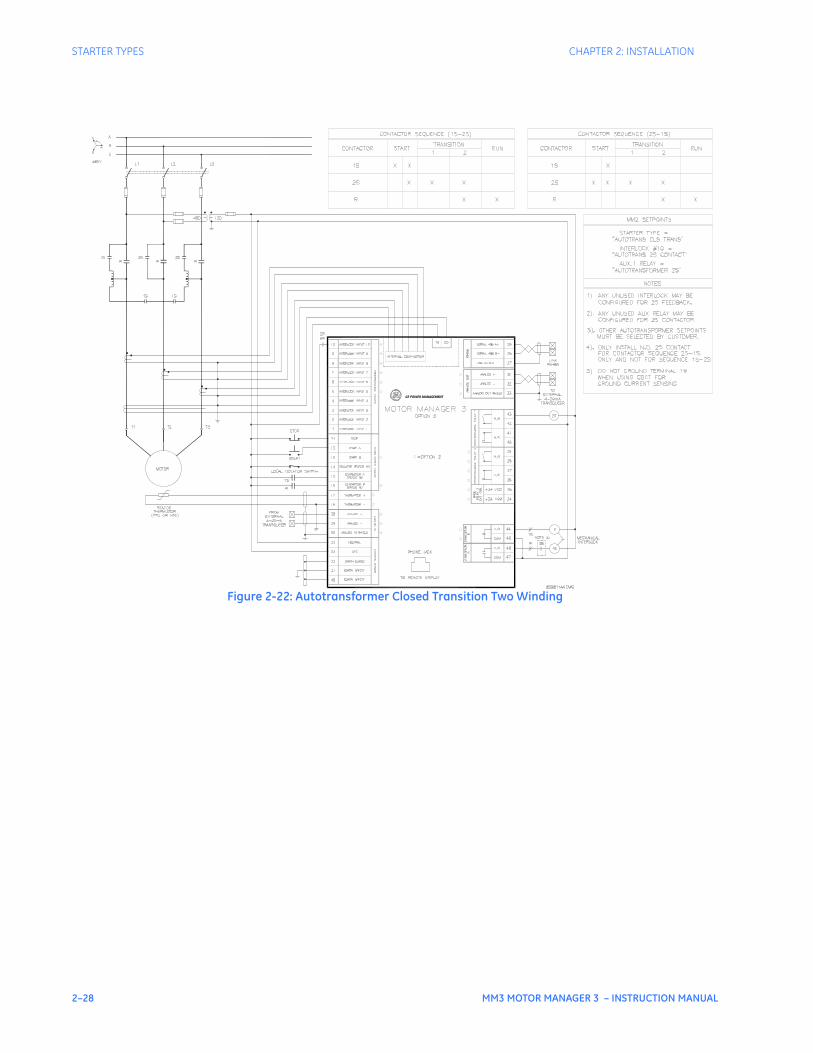
2–28 MM3 MOTOR MANAGER 3 – INSTRUCTION MANUAL
STARTER TYPES CHAPTER 2: INSTALLATION
Figure 2-22: Autotransformer Closed Transition Two Winding
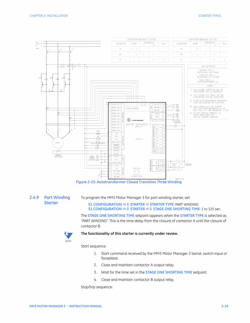
CHAPTER 2: INSTALLATION STARTER TYPES
MM3 MOTOR MANAGER 3 – INSTRUCTION MANUAL 2–29
Figure 2-23: Autotransformer Closed Transition Three Winding
2.4.9 Part Winding Starter
To program the MM3 Motor Manager 3 for part winding starter, set:
S1 CONFIGURATION STARTER STARTER TYPE: PART WINDINGS1 CONFIGURATION STARTER STAGE ONE SHORTING TIME: 1 to 125 sec.
The STAGE ONE SHORTING TIME setpoint appears when the STARTER TYPE is selected as “PART WINDING”. This is the time delay from the closure of contactor A until the closure of contactor B.
The functionality of this starter is currently under review.
Start sequence:
1. Start command received by the MM3 Motor Manager 3 (serial, switch input or faceplate).
2. Close and maintain contactor A output relay.
3. Wait for the time set in the STAGE ONE SHORTING TIME setpoint.
4. Close and maintain contactor B output relay.
Stop/trip sequence:
NOTE
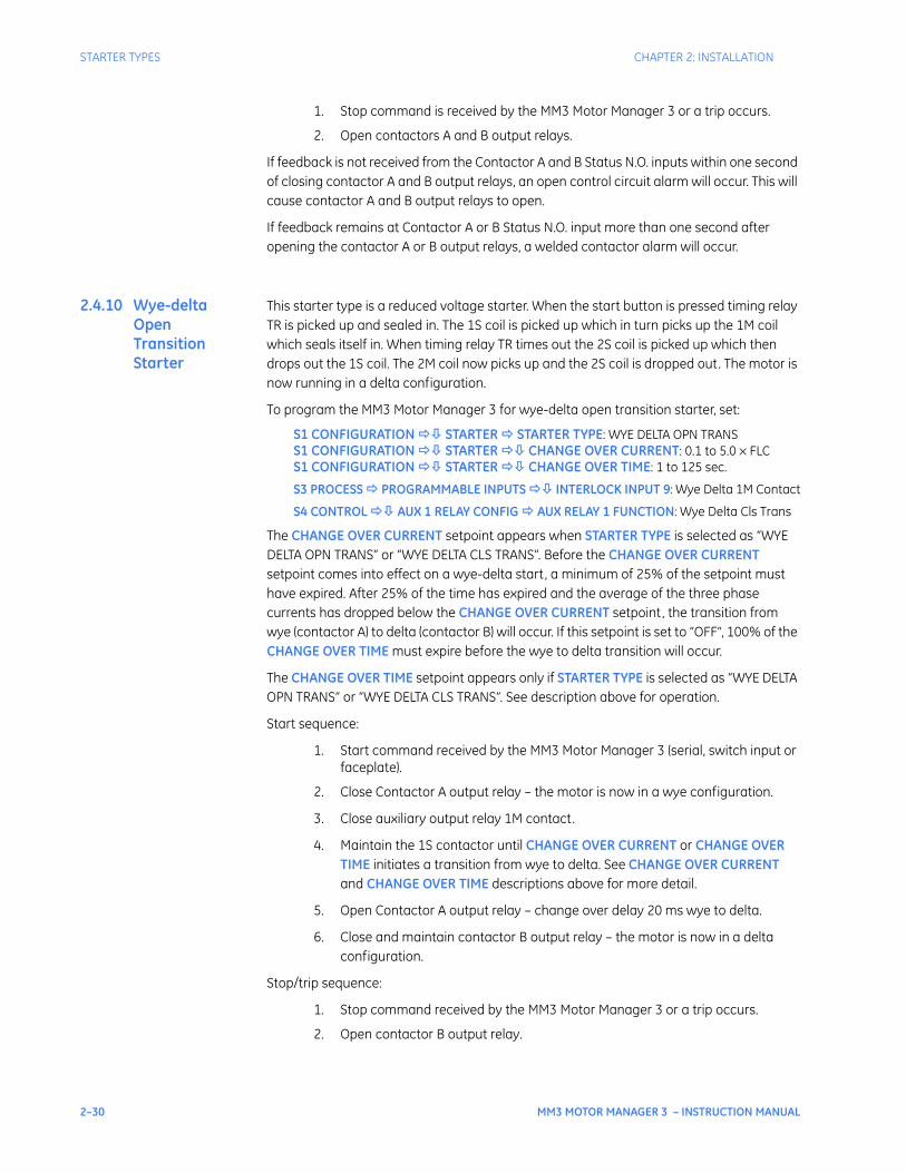
2–30 MM3 MOTOR MANAGER 3 – INSTRUCTION MANUAL
STARTER TYPES CHAPTER 2: INSTALLATION
1. Stop command is received by the MM3 Motor Manager 3 or a trip occurs.
2. Open contactors A and B output relays.
If feedback is not received from the Contactor A and B Status N.O. inputs within one second of closing contactor A and B output relays, an open control circuit alarm will occur. This will cause contactor A and B output relays to open.
If feedback remains at Contactor A or B Status N.O. input more than one second after opening the contactor A or B output relays, a welded contactor alarm will occur.
2.4.10 Wye-delta Open Transition Starter
This starter type is a reduced voltage starter. When the start button is pressed timing relay TR is picked up and sealed in. The 1S coil is picked up which in turn picks up the 1M coil which seals itself in. When timing relay TR times out the 2S coil is picked up which then drops out the 1S coil. The 2M coil now picks up and the 2S coil is dropped out. The motor is now running in a delta configuration.
To program the MM3 Motor Manager 3 for wye-delta open transition starter, set:
S1 CONFIGURATION STARTER STARTER TYPE: WYE DELTA OPN TRANSS1 CONFIGURATION STARTER CHANGE OVER CURRENT: 0.1 to 5.0 × FLCS1 CONFIGURATION STARTER CHANGE OVER TIME: 1 to 125 sec.
S3 PROCESS PROGRAMMABLE INPUTS INTERLOCK INPUT 9: Wye Delta 1M Contact
S4 CONTROL AUX 1 RELAY CONFIG AUX RELAY 1 FUNCTION: Wye Delta Cls Trans
The CHANGE OVER CURRENT setpoint appears when STARTER TYPE is selected as “WYE DELTA OPN TRANS” or “WYE DELTA CLS TRANS”. Before the CHANGE OVER CURRENT setpoint comes into effect on a wye-delta start, a minimum of 25% of the setpoint must have expired. After 25% of the time has expired and the average of the three phase currents has dropped below the CHANGE OVER CURRENT setpoint, the transition from wye (contactor A) to delta (contactor B) will occur. If this setpoint is set to “OFF”, 100% of the CHANGE OVER TIME must expire before the wye to delta transition will occur.
The CHANGE OVER TIME setpoint appears only if STARTER TYPE is selected as “WYE DELTA OPN TRANS” or “WYE DELTA CLS TRANS”. See description above for operation.
Start sequence:
1. Start command received by the MM3 Motor Manager 3 (serial, switch input or faceplate).
2. Close Contactor A output relay – the motor is now in a wye configuration.
3. Close auxiliary output relay 1M contact.
4. Maintain the 1S contactor until CHANGE OVER CURRENT or CHANGE OVER TIME initiates a transition from wye to delta. See CHANGE OVER CURRENT and CHANGE OVER TIME descriptions above for more detail.
5. Open Contactor A output relay – change over delay 20 ms wye to delta.
6. Close and maintain contactor B output relay – the motor is now in a delta configuration.
Stop/trip sequence:
1. Stop command received by the MM3 Motor Manager 3 or a trip occurs.
2. Open contactor B output relay.
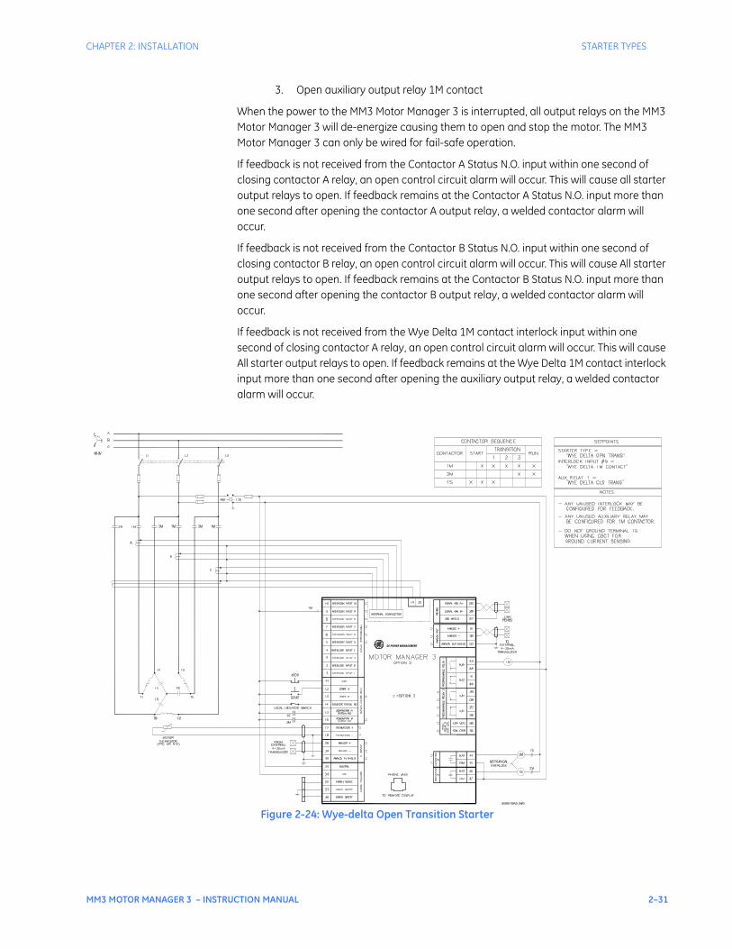
CHAPTER 2: INSTALLATION STARTER TYPES
MM3 MOTOR MANAGER 3 – INSTRUCTION MANUAL 2–31
3. Open auxiliary output relay 1M contact
When the power to the MM3 Motor Manager 3 is interrupted, all output relays on the MM3 Motor Manager 3 will de-energize causing them to open and stop the motor. The MM3 Motor Manager 3 can only be wired for fail-safe operation.
If feedback is not received from the Contactor A Status N.O. input within one second of closing contactor A relay, an open control circuit alarm will occur. This will cause all starter output relays to open. If feedback remains at the Contactor A Status N.O. input more than one second after opening the contactor A output relay, a welded contactor alarm will occur.
If feedback is not received from the Contactor B Status N.O. input within one second of closing contactor B relay, an open control circuit alarm will occur. This will cause All starter output relays to open. If feedback remains at the Contactor B Status N.O. input more than one second after opening the contactor B output relay, a welded contactor alarm will occur.
If feedback is not received from the Wye Delta 1M contact interlock input within one second of closing contactor A relay, an open control circuit alarm will occur. This will cause All starter output relays to open. If feedback remains at the Wye Delta 1M contact interlock input more than one second after opening the auxiliary output relay, a welded contactor alarm will occur.
Figure 2-24: Wye-delta Open Transition Starter
GE POWER MANAGEMENT

2–32 MM3 MOTOR MANAGER 3 – INSTRUCTION MANUAL
STARTER TYPES CHAPTER 2: INSTALLATION
2.4.11 Wye-delta Closed Transition Starter
This starter type is a reduced voltage starter. When the start button is pressed timing relay TR is picked up and sealed in. The 1S coil is picked up which in turn picks up the 1M coil which seals itself in. When timing relay TR times out the 2S coil is picked up which then drops out the 1S coil. The 2M coil now picks up and the 2S coil is dropped out. The motor is now running in a delta configuration.
Figure 2-25: Elementary Wye-delta Closed Transition Magnetic Starter
To program the MM3 Motor Manager 3 for wye-delta closed transition starter, set:
S1 CONFIGURATION STARTER STARTER TYPE: WYE DELTA CLS TRANSS1 CONFIGURATION STARTER CHANGE OVER CURRENT: 0.1 to 5.0 × FLCS1 CONFIGURATION STARTER CHANGE OVER TIME: 1 to 125 sec.
S3 PROCESS PROGRAMMABLE INPUTS INTERLOCK INPUT 9: Wye Delta 2S ContactS3 PROCESS PROGRAMMABLE INPUTS INTERLOCK INPUT 10: Wye Delta 1M Contact
S4 CONTROL AUX 1 RELAY CONFIG AUX RELAY 1 FUNCTION: Wye Delta Cls Trans
The CHANGE OVER CURRENT setpoint appears only if either of the wye-delta starter types have been selected. Before the CHANGE OVER CURRENT setpoint comes into effect on a Wye delta start, a minimum of 25% of the CHANGE OVER TIME setpoint must have expired. After 25% of the time has expired and the average of the three phase currents has dropped below the CHANGE OVER CURRENT value, the transition from wye (contactor A) to delta (contactor B) will occur. If this setpoint is set to “OFF”, 100% of the CHANGE OVER TIME must expire before the wye to delta transition will occur.
The CHANGE OVER TIME setpoint appears only if the wye-delta starter type has been selected. See the description above for operation.
Start sequence:
1. Start command received by the MM3 Motor Manager 3.
2. Close the contactor A relay – this causes the 1S wye contactor to pick up which connects the motor windings in the wye configuration.
3. Wait approximately 20 ms.

CHAPTER 2: INSTALLATION STARTER TYPES
MM3 MOTOR MANAGER 3 – INSTRUCTION MANUAL 2–33
4. Close auxiliary relay 1 – this causes the 1M contactor to pick up and start the motor.
5. Maintain 1S and 1M contactors until CHANGE OVER CURRENT or CHANGE OVER TIME initiates a transition from wye to delta. See the description above for more detail.
6. Close the contactor B relay – this causes the 2S resistor contactor to pick up which connects the resistors across the line.
7. Wait approximately 20 ms.
8. Open the contactor A output relay. This causes the 1S wye contactor to drop out. The normally closed auxiliary contacts on the 1S wye contactor pick up the 2M delta contactor which connects the motor in the delta configuration. The normally closed auxiliary contacts on the 2M contactor drop out the 2S resistor contactor.
Stop/trip sequence:
1. Stop command received by the MM3 Motor Manager 3 or a trip occurs.
2. Open the 1M and 2M contactors.
When the power to the MM3 Motor Manager 3 is interrupted, all output relays will de-energize, causing them to open and stop the motor. The MM3 Motor Manager 3 can only be wired for fail-safe operation.
If feedback is not received by the Contactor A Status N.O., Contactor B Status N.O. or the wye-delta 1M contact inputs within one second of closing the corresponding output relay, an open control circuit alarm will occur. This will open all three output relays which will stop the motor.
If feedback remains at the programmable switch input that has been configured to a wye-delta 2S contact for more than one second, a welded contactor alarm will occur. This will open all three output relays which will stop the motor. This will prevent the resistors from burning out if the 2S contactor does not open after switching to the delta configuration.
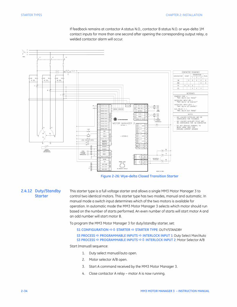
2–34 MM3 MOTOR MANAGER 3 – INSTRUCTION MANUAL
STARTER TYPES CHAPTER 2: INSTALLATION
If feedback remains at contactor A status N.O., contactor B status N.O. or wye-delta 1M contact inputs for more than one second after opening the corresponding output relay, a welded contactor alarm will occur.
Figure 2-26: Wye-delta Closed Transition Starter
2.4.12 Duty/Standby Starter
This starter type is a full voltage starter and allows a single MM3 Motor Manager 3 to control two identical motors. This starter type has two modes, manual and automatic. In manual mode a switch input determines which of the two motors is available for operation. In automatic mode the MM3 Motor Manager 3 selects which motor should run based on the number of starts performed. An even number of starts will start motor A and an odd number will start motor B.
To program the MM3 Motor Manager 3 for duty/standby starter, set:
S1 CONFIGURATION STARTER STARTER TYPE: DUTY/STANDBY
S3 PROCESS PROGRAMMABLE INPUTS INTERLOCK INPUT 1: Duty Select Man/AutoS3 PROCESS PROGRAMMABLE INPUTS INTERLOCK INPUT 2: Motor Selector A/B
Start (manual) sequence:
1. Duty select manual/auto open.
2. Motor selector A/B open.
3. Start A command received by the MM3 Motor Manager 3.
4. Close contactor A relay – motor A is now running.
GE POWER MANAGEMENT

CHAPTER 2: INSTALLATION STARTER TYPES
MM3 MOTOR MANAGER 3 – INSTRUCTION MANUAL 2–35
5. Stop command.
6. Motor selector A/B closed.
7. Start A command received by the MM3 Motor Manager 3.
8. Close contactor B relay – motor B is now running.
Start (auto) sequence:
1. Duty select manual/auto closed.
2. Motor selector A/B has no effect.
3. Start A command received by the MM3 Motor Manager 3 (number of starts = 0, even).
4. Close contactor A relay – motor A is now running.
5. Stop command.
6. Start A command received by the MM3 Motor Manager 3 (number of starts = 1, odd).
7. Close contactor B relay – motor B is now running.
Stop/trip sequence:
1. Stop command received by the MM3 Motor Manager 3 or a trip occurs.
2. Open the active contactor A or B.
When the power to the MM3 Motor Manager 3 is interrupted, all output relays will de-energize, causing them to open and stop the motor. The MM3 Motor Manager 3 can only be wired for fail-safe operation.
If feedback is not received by the Contactor A Status N.O. or Contactor B Status N.O. inputs within one second of closing the corresponding output relay, an OPEN CONTROL CIRCUIT alarm will occur. This will open the active output relay which will stop the motor.
If feedback remains at Contactor A Status N.O. or Contactor B Status N.O. inputs for more than one second after opening the corresponding output relay, a welded contactor alarm will occur.
The Start A input and key are used to start motors A and B. The Start B input and faceplate key have no effect.
Serial control starts override the mode of operation of the duty/standby starter. For example a serial start B command will always start motor B and a serial start A will always start motor A. This is true for Auto Start A and Auto Start B programmable interlock functions as well.
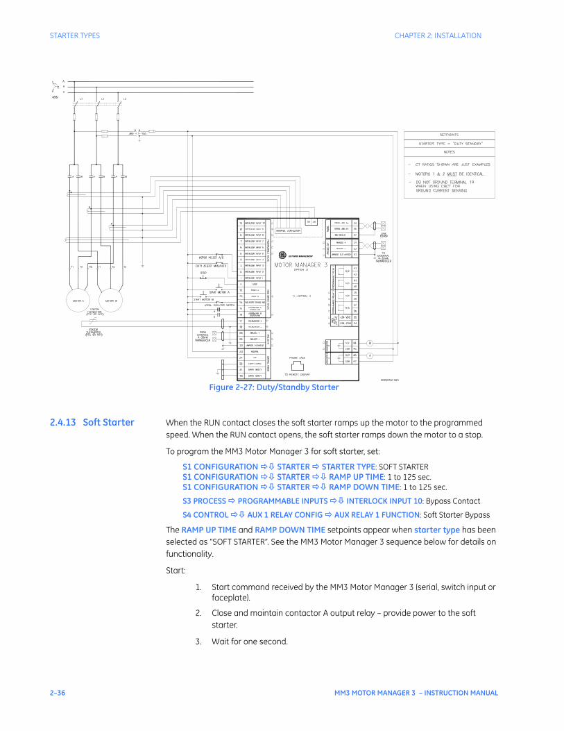
2–36 MM3 MOTOR MANAGER 3 – INSTRUCTION MANUAL
STARTER TYPES CHAPTER 2: INSTALLATION
Figure 2-27: Duty/Standby Starter
2.4.13 Soft Starter When the RUN contact closes the soft starter ramps up the motor to the programmed speed. When the RUN contact opens, the soft starter ramps down the motor to a stop.
To program the MM3 Motor Manager 3 for soft starter, set:
S1 CONFIGURATION STARTER STARTER TYPE: SOFT STARTERS1 CONFIGURATION STARTER RAMP UP TIME: 1 to 125 sec.S1 CONFIGURATION STARTER RAMP DOWN TIME: 1 to 125 sec.
S3 PROCESS PROGRAMMABLE INPUTS INTERLOCK INPUT 10: Bypass Contact
S4 CONTROL AUX 1 RELAY CONFIG AUX RELAY 1 FUNCTION: Soft Starter Bypass
The RAMP UP TIME and RAMP DOWN TIME setpoints appear when starter type has been selected as “SOFT STARTER”. See the MM3 Motor Manager 3 sequence below for details on functionality.
Start:
1. Start command received by the MM3 Motor Manager 3 (serial, switch input or faceplate).
2. Close and maintain contactor A output relay – provide power to the soft starter.
3. Wait for one second.
GE POWER MANAGEMENT

CHAPTER 2: INSTALLATION STARTER TYPES
MM3 MOTOR MANAGER 3 – INSTRUCTION MANUAL 2–37
4. Close and maintain contactor B output relay – signal the soft starter to start the motor.
5. Wait for the RAMP UP TIME for contactor B status N.O. to close.
6. Close bypass contact auxiliary relay (optional)
Stop/trip:
1. Stop command is received or a trip occurs (serial, switch input or faceplate).
2. Open contactor B output relay.
3. Open bypass contact auxiliary relay (optional).
4. Wait for the RAMP DOWN TIME for Contactor B Status N.O. to open.
5. When Contactor B Status N.O. reads open, open contactor A output relay.
If feedback is not received from the 1M contact to the Contactor A Status N.O. input within one second of closing Contactor A output relay, an open control circuit alarm will occur. This will cause Contactor A and B output relays to open.
If Contactor B Status N.O. does not receive feedback from the up to speed contact on the soft starter within the RAMP UP TIME setpoint during a start, a drive failed to start alarm will be generated. If Contactor B Status N.O. feedback remains at the MM3 Motor Manager 3 after the RAMP DOWN TIME has expired during a stop, a drive failed to stop alarm will be generated.
If feedback remains at Contactor A Status N.O. input more than 1 second after opening the Contactor A output relay, a welded contactor alarm occurs. If feedback remains at the Interlock configured for bypass contact more than one second after opening the auxiliary output relay, a welded contactor alarm occurs. If feedback is not received from the bypass contact interlock input within one second of closing auxiliary output relay, an open control circuit alarm occurs. This will cause contactor A and B output relays to open.
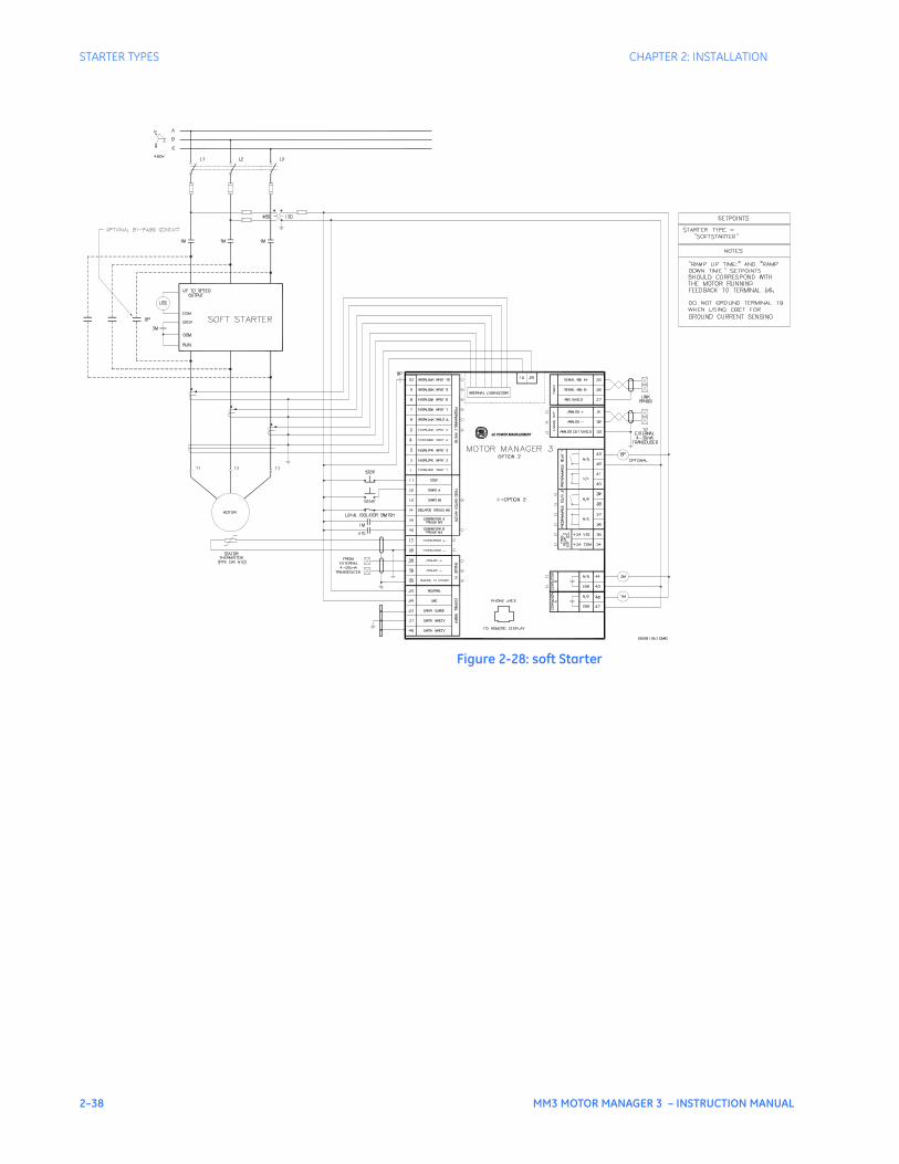
2–38 MM3 MOTOR MANAGER 3 – INSTRUCTION MANUAL
STARTER TYPES CHAPTER 2: INSTALLATION
Figure 2-28: soft Starter
GE POWER MANAGEMENT

MM3 MOTOR MANAGER 3 – INSTRUCTION MANUAL 3–1
MM3 Motor Manager 3
Chapter 3: Hardware
GE Consumer & IndustrialMultilin
STOP
RUNNING RELAY ARELAY A
STOPPED RELAY BRELAY B
TRIPPED AUX RELAY 1AUX RELAY 1
ALARM AUX RELAY 2AUX RELAY 2
VALUE
MESSAGE
AUTO MANUAL
STORE
RESET
ACTUAL
SETPOINT
START
A
START
A
START
B
START
B
Hardware
3.1 User interface
3.1.1 Description Once the MM3 has been wired and powered on, it is ready to be programmed for a specific application. Local programming is done using the front panel keypad and the 40-character alphanumeric display. Remote programming via the serial port is also possible using the EnerVista MM3 Setup software.
3.1.2 Message Display
A 40-character display communicates system information to the user. Trip and alarm messages automatically override the currently-displayed message. If no key is pressed for two minutes, a user-selected default messaging sequence will be displayed. If the motor is currently stopped, the MOTOR STATUS message will be the default message. Once the motor is started, the first user-selected message appears.
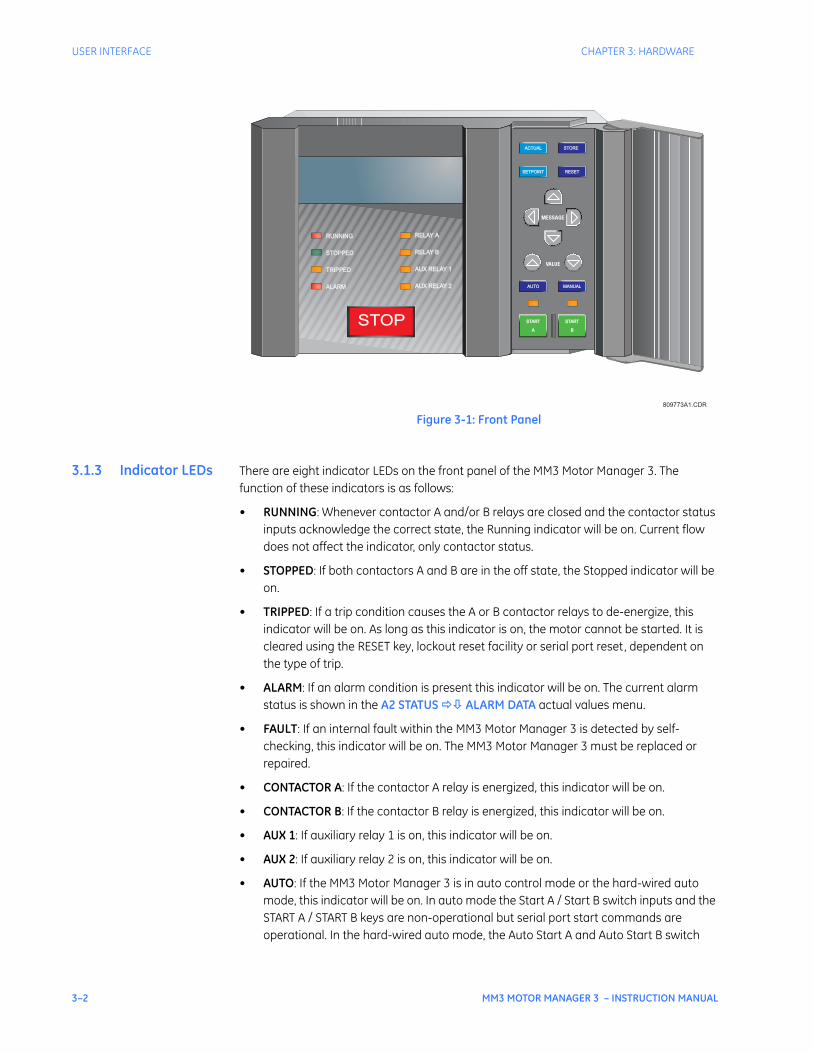
3–2 MM3 MOTOR MANAGER 3 – INSTRUCTION MANUAL
USER INTERFACE CHAPTER 3: HARDWARE
Figure 3-1: Front Panel
3.1.3 Indicator LEDs There are eight indicator LEDs on the front panel of the MM3 Motor Manager 3. The function of these indicators is as follows:
• RUNNING: Whenever contactor A and/or B relays are closed and the contactor status inputs acknowledge the correct state, the Running indicator will be on. Current flow does not affect the indicator, only contactor status.
• STOPPED: If both contactors A and B are in the off state, the Stopped indicator will be on.
• TRIPPED: If a trip condition causes the A or B contactor relays to de-energize, this indicator will be on. As long as this indicator is on, the motor cannot be started. It is cleared using the RESET key, lockout reset facility or serial port reset, dependent on the type of trip.
• ALARM: If an alarm condition is present this indicator will be on. The current alarm status is shown in the A2 STATUS ALARM DATA actual values menu.
• FAULT: If an internal fault within the MM3 Motor Manager 3 is detected by self-checking, this indicator will be on. The MM3 Motor Manager 3 must be replaced or repaired.
• CONTACTOR A: If the contactor A relay is energized, this indicator will be on.
• CONTACTOR B: If the contactor B relay is energized, this indicator will be on.
• AUX 1: If auxiliary relay 1 is on, this indicator will be on.
• AUX 2: If auxiliary relay 2 is on, this indicator will be on.
• AUTO: If the MM3 Motor Manager 3 is in auto control mode or the hard-wired auto mode, this indicator will be on. In auto mode the Start A / Start B switch inputs and the START A / START B keys are non-operational but serial port start commands are operational. In the hard-wired auto mode, the Auto Start A and Auto Start B switch
809773A1.CDR
STOP
RUNNING RELAY ARELAY A
STOPPED RELAY BRELAY B
TRIPPED AUX RELAY 1AUX RELAY 1
ALARM AUX RELAY 2AUX RELAY 2
VALUE
MESSAGE
AUTO MANUAL
STORE
RESET
ACTUAL
SETPOINT
START
A
START
A
START
B
START
B

CHAPTER 3: HARDWARE USER INTERFACE
MM3 MOTOR MANAGER 3 – INSTRUCTION MANUAL 3–3
inputs are functional in conjunction with the Auto Permissive switch input. Serial, faceplate and remote starts are disabled. STOP commands from any location are always operational.
• MANUAL: If the MM3 Motor Manager 3 is in manual control mode, this indicator will be on. In manual mode the Start A / Start B switch inputs, Auto Start A / Auto Start B switch inputs and START A / START B keys are operational but serial port start commands are ignored. All stop commands are operational.
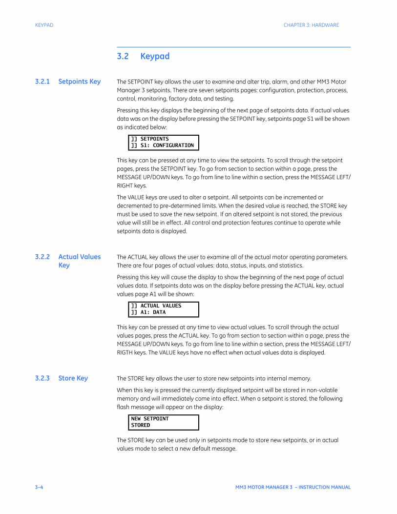
3–4 MM3 MOTOR MANAGER 3 – INSTRUCTION MANUAL
KEYPAD CHAPTER 3: HARDWARE
3.2 Keypad
3.2.1 Setpoints Key The SETPOINT key allows the user to examine and alter trip, alarm, and other MM3 Motor Manager 3 setpoints. There are seven setpoints pages: configuration, protection, process, control, monitoring, factory data, and testing.
Pressing this key displays the beginning of the next page of setpoints data. If actual values data was on the display before pressing the SETPOINT key, setpoints page S1 will be shown as indicated below:
This key can be pressed at any time to view the setpoints. To scroll through the setpoint pages, press the SETPOINT key. To go from section to section within a page, press the MESSAGE UP/DOWN keys. To go from line to line within a section, press the MESSAGE LEFT/RIGHT keys.
The VALUE keys are used to alter a setpoint. All setpoints can be incremented or decremented to pre-determined limits. When the desired value is reached, the STORE key must be used to save the new setpoint. If an altered setpoint is not stored, the previous value will still be in effect. All control and protection features continue to operate while setpoints data is displayed.
3.2.2 Actual Values Key
The ACTUAL key allows the user to examine all of the actual motor operating parameters. There are four pages of actual values: data, status, inputs, and statistics.
Pressing this key will cause the display to show the beginning of the next page of actual values data. If setpoints data was on the display before pressing the ACTUAL key, actual values page A1 will be shown:
This key can be pressed at any time to view actual values. To scroll through the actual values pages, press the ACTUAL key. To go from section to section within a page, press the MESSAGE UP/DOWN keys. To go from line to line within a section, press the MESSAGE LEFT/RIGTH keys. The VALUE keys have no effect when actual values data is displayed.
3.2.3 Store Key The STORE key allows the user to store new setpoints into internal memory.
When this key is pressed the currently displayed setpoint will be stored in non-volatile memory and will immediately come into effect. When a setpoint is stored, the following flash message will appear on the display:
The STORE key can be used only in setpoints mode to store new setpoints, or in actual values mode to select a new default message.
]] SETPOINTS]] S1: CONFIGURATION
]] ACTUAL VALUES]] A1: DATA
NEW SETPOINTSTORED

CHAPTER 3: HARDWARE KEYPAD
MM3 MOTOR MANAGER 3 – INSTRUCTION MANUAL 3–5
3.2.4 Stop Key The STOP key allows the user to stop the motor directly from the MM3 Motor Manager 3 faceplate interface.
Pressing this key causes the contactor A and contactor B output relays to de-energize, therefore dropping out the motor contactor. The STOP key is used to stop the motor.
3.2.5 Reset Key The RESET key allows the user to reset MM3 Motor Manager 3 trips.
Pressing this key will reset a tripped state on the MM3 Motor Manager 3. A message indicating that a reset is not possible will be displayed if the condition causing the trip is still present.
The RESET key can be used to reset all trip conditions from the faceplate. A ground fault, stalled rotor and overload trip can be assigned to the lockout reset feature on one of the programmable switch inputs for added safety. The factory default allows the resetting of all trips using the front panel reset key.
3.2.6 Start A/B Keys The START A/B keys can be used to start the motor.
Pressing these keys will cause the programmed start sequence to begin. The START A/B keys are used to start the motor from the faceplate of the MM3 Motor Manager 3. Start A/B can also be initiated from the start switch inputs at the back of the MM3 Motor Manager 3 or from the serial port.
3.2.7 Message Up/Down Keys
The MESSAGE UP/DOWN keys allow the user to move to the next or previous section of the currently selected page.
Pressing the MESSAGE DOWN key displays the next section of the current page. Pressing the MESSAGE UP key displays the previous section of the current page. Note: If either key is held for more than 1 second, the next or previous sections will be selected at a fast rate. When the current display is at a page heading, the MESSAGE UP key has no effect. When the current display is at the end of the page, the MESSAGE DOWN key has no effect.
3.2.8 Message Left/Right Keys
The MESSAGE RIGHT and LEFT keys allow the user to scan the next or previous line of the currently selected section.
Pressing the MESSAGE RIGHT key displays the next line of the current section. Pressing the MESSAGE LEFT key displays the previous line of the current section. If either key is held for more than one second, the next or previous line will be selected at a fast rate. If the display shows a section heading, the MESSAGE LEFT key will have no effect. If the MESSAGE RIGHT key has no effect, the display is showing the last line of a section.
3.2.9 Value Keys The VALUE keys allow the user to change setpoint values prior to pressing the STORE key.
Pressing the VALUE UP key will increment the currently displayed setpoint value. Pressing the VALUE DOWN key will decrement the currently displayed setpoint value. If the display shows an actual value these keys will have no effect

3–6 MM3 MOTOR MANAGER 3 – INSTRUCTION MANUAL
HARDWARE DESCRIPTION CHAPTER 3: HARDWARE
3.3 Hardware Description
3.3.1 MM3 Motor Manager 3 Design
A 16 bit 68HC16 microcontroller IC performs program execution and control logic for the MM3 Motor Manager 3. It has an 8 or 16 bit bus width which can be selected dynamically with each external memory fetch allowing a mix of 8 and 16 bit devices. Internal clock rate is 16 Mhz. Instructions are stored in a 512K × 8 bit flash memory, data is stored in an 32K × 8 RAM while setpoints and accumulated data are stored in a 8K × 8 EEPROM.
An intelligent display module with its own microprocessor, memory and command set is accessed through communications channel on the main CPU board. The display, a 4 × 4 keypad and the front panel LEDs data are exchanged via modbus data packets.
External switch inputs are driven with the same voltage applied to the control voltage 120 or 240 V AC which triggers an optocoupler for isolation. All control logic based on the state of these inputs determines operation of up to 4 output relays which are also driven from a latch under program control. Like the inputs, the relay outputs are driven from an isolated power supply and optocoupler to prevent switching transient energy from affecting the CPU.
A 10-bit successive approximation A/D on the 68HC16 CPU with eight channels is used to measure all analog signals. Separate AC inputs for phase 1, phase 2, phase 3, and ground fault signals are sampled at a 1.67 ms rate, squared and summed. RMS current is then determined by deriving the square root of the sampled waveform over several cycles. The sampling time is set to measure an integral number of cycles to reduce the affects of noise and harmonics. Thermistor, analog input, control supply voltage and internal reference voltage are also monitored. An external precision 5 V DC reference is used as the input reference for the A/D converter.
When power to the unit is removed, a small 8-bit processor (68HC908) will continue to operate for a period of at least 1 hour. This processor is powered from a large backup capacitor. The 68HC908 accurately measures the time that the MM3 Motor Manager 3 has been without control power. When power is re-applied the main processor will read the time off from the small processor and then very accurately calculate the thermal capacity value. This time off value is also used for the undervoltage restart feature.
Serial communications at up to 57600 baud is implemented with a UART. All necessary timing and control is performed inside the chip. An external transceiver chip converts the digital data to an RS485 interface. Direction, receive data and transmit data are on the input side with a two wire twisted pair driver on the output.
AC control voltage to power the MM3 Motor Manager 3 can be selected as 120 or 240 V AC using a switch and dual wound primary transformer. A filter is incorporated between the incoming supply and transformer primary to prevent transients from affecting the circuitry.
Separate, isolated secondary supplies are used for CPU power, input/output and communication drivers. Optocoupling and transformer coupling are used between isolated circuits to prevent transients from upsetting program execution. The 68HC908 is used to provide separate watchdog timer and power fail monitoring control to ensure that the main CPU starts and operates under any input voltage conditions. Should normal program execution fail, the 68HC908 resets the main CPU.

MM3 MOTOR MANAGER 3 – INSTRUCTION MANUAL 4–1
MM3 Motor Manager 3
Chapter 4: Software
GE Consumer & IndustrialMultilin
STOP
RUNNING RELAY ARELAY A
STOPPED RELAY BRELAY B
TRIPPED AUX RELAY 1AUX RELAY 1
ALARM AUX RELAY 2AUX RELAY 2
VALUE
MESSAGE
AUTO MANUAL
STORE
RESET
ACTUAL
SETPOINT
START
A
START
A
START
B
START
B
Software
4.1 Overview
4.1.1 Description Although setpoints can be entered manually using the front panel keys, it is much easier to use a computer to download values through the communications port. The EnerVista MM3 Setup software is available from GE Multilin to make this as convenient as possible. With EnerVista MM3 Setup running, it is possible to:
• Program/modify setpoints
• Load/save setpoint files from/to disk
• Read actual values
• Monitor status
• Read pre-trip data and trip record
• Get help on any topic
• Upgrade MM3 Motor Manager 3 firmware
• View the instruction manual as a help file
The EnerVista MM3 Setup software allows immediate access to all MM3 Motor Manager 3 features with easy to use pull down menus in the familiar Windows environment. This chapter provides the necessary information to install EnerVista MM3 Setup, upgrade the relay firmware, and write/edit setpoint files.
The EnerVista MM3 Setup software can run without a MM3 Motor Manager 3 connected to the computer. In this case, settings may be saved to a file for future use. If an MM3 Motor Manager 3 is connected to a PC and communications are enabled, the MM3 Motor Manager 3 can be programmed from the setpoint screens. In addition, measured values, status and trip messages can be displayed with the actual value screens.

4–2 MM3 MOTOR MANAGER 3 – INSTRUCTION MANUAL
OVERVIEW CHAPTER 4: SOFTWARE
4.1.2 Requirements The following minimum requirements must be met for the EnerVista MM3 Setup software to operate on the computer.
• Microsoft Windows™ 95/98 or higher is installed and running properly
• at least 6 MB hard disk space is available
EnerVista MM3 Setup can be installed from either the GE EnerVista CD or the GE Multilin website at http://www.GEmultilin.com. If you are using legacy equipment without web access or a CD drive, 3.5” floppy disks can be ordered from the factory.
4.1.3 Checking if Installation/Upgrade is Required
It may be necessary to upgrade an existing version of EnerVista MM3 Setup. Start the software and follow the procedure below:
While EnerVista MM3 Setup is running, insert the GE Multilin CD or go to the GE Multilin website at http://www.GEmultilin.com (preferred method).
Select the Software menu item then select MM3 Motor Manager 3 from the list of products.
Verify that the software version shown on this page is identical to the installed version as shown below. Select the Help > About MM3PC menu item to determine which version is installed on the local PC.
4.1.4 Installing EnerVista MM3 Setup
After ensuring the minimum requirements indicated earlier, use the following procedure to install the EnerVista MM3 Setup software from the enclosed GE EnerVista CD.
Insert the GE EnerVista CD into your CD-ROM drive.
Click the Install Now button and follow the installation instructions to install the no-charge EnerVista software on the local PC.
When installation is complete, start the EnerVista Launchpad application.
Click the IED Setup section of the Launch Pad toolbar.
Figure 4-1: EnerVista Launchpad Toolbar
In the EnerVista Launch Pad window, click the Add Product button and select the “MM3 Motor Manager 3 Intelligent MCC Controller” as shown below.
Select the “Web” option to ensure the most recent software release, or select “CD” if you do not have a web connection.
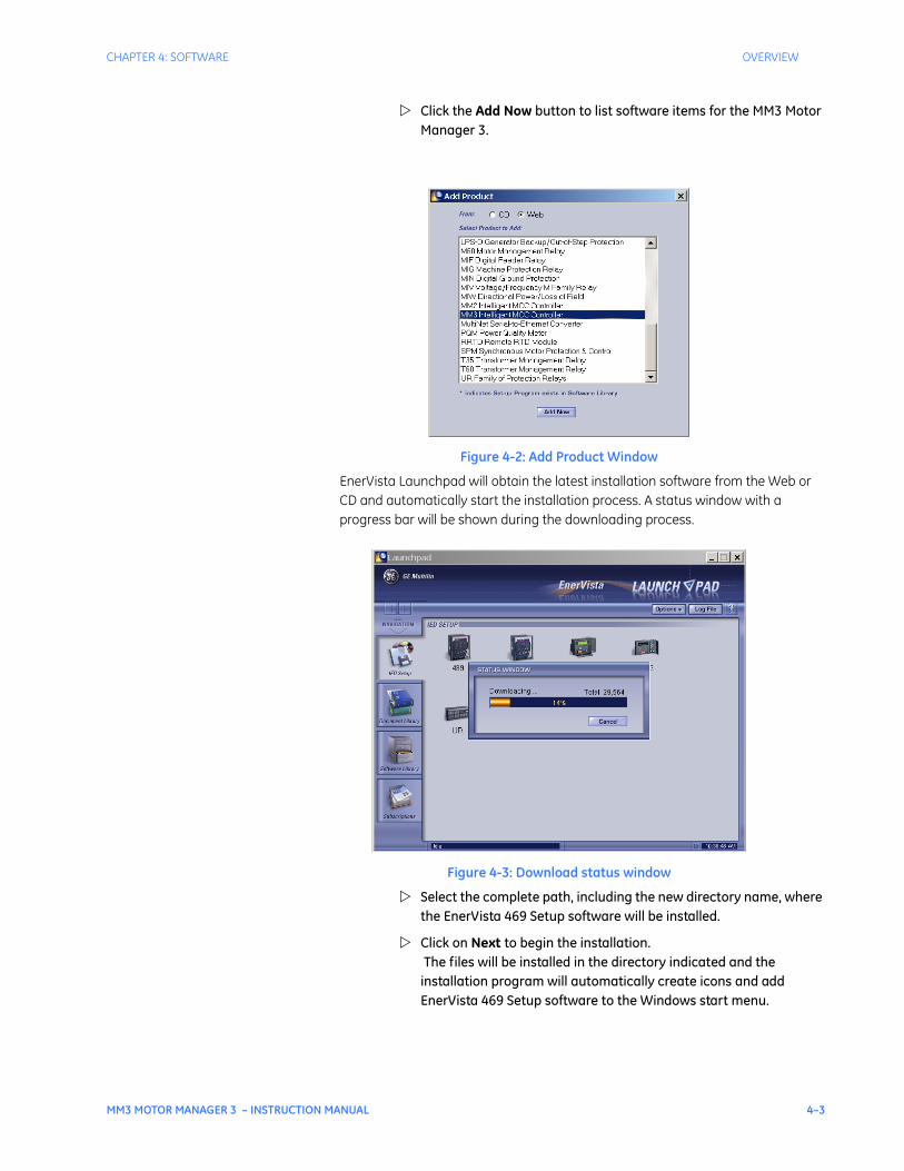
CHAPTER 4: SOFTWARE OVERVIEW
MM3 MOTOR MANAGER 3 – INSTRUCTION MANUAL 4–3
Click the Add Now button to list software items for the MM3 Motor Manager 3.
Figure 4-2: Add Product Window
EnerVista Launchpad will obtain the latest installation software from the Web or CD and automatically start the installation process. A status window with a progress bar will be shown during the downloading process.
Figure 4-3: Download status window
Select the complete path, including the new directory name, where the EnerVista 469 Setup software will be installed.
Click on Next to begin the installation. The files will be installed in the directory indicated and the installation program will automatically create icons and add EnerVista 469 Setup software to the Windows start menu.
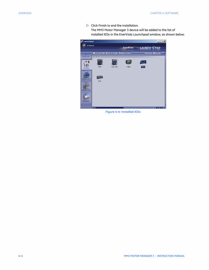
4–4 MM3 MOTOR MANAGER 3 – INSTRUCTION MANUAL
OVERVIEW CHAPTER 4: SOFTWARE
Click Finish to end the installation. The MM3 Motor Manager 3 device will be added to the list of installed IEDs in the EnerVista Launchpad window, as shown below.
Figure 4-4: Installed IEDs
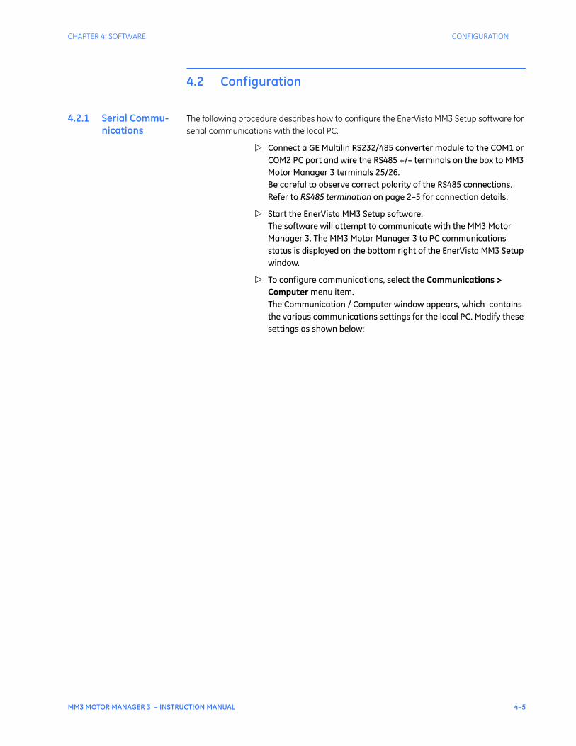
CHAPTER 4: SOFTWARE CONFIGURATION
MM3 MOTOR MANAGER 3 – INSTRUCTION MANUAL 4–5
4.2 Configuration
4.2.1 Serial Commu-nications
The following procedure describes how to configure the EnerVista MM3 Setup software for serial communications with the local PC.
Connect a GE Multilin RS232/485 converter module to the COM1 or COM2 PC port and wire the RS485 +/– terminals on the box to MM3 Motor Manager 3 terminals 25/26. Be careful to observe correct polarity of the RS485 connections. Refer to RS485 termination on page 2–5 for connection details.
Start the EnerVista MM3 Setup software. The software will attempt to communicate with the MM3 Motor Manager 3. The MM3 Motor Manager 3 to PC communications status is displayed on the bottom right of the EnerVista MM3 Setup window.
To configure communications, select the Communications > Computer menu item. The Communication / Computer window appears, which contains the various communications settings for the local PC. Modify these settings as shown below:
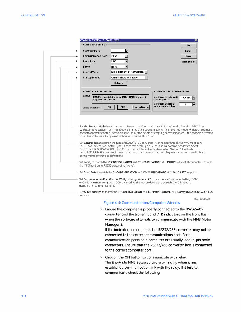
4–6 MM3 MOTOR MANAGER 3 – INSTRUCTION MANUAL
CONFIGURATION CHAPTER 4: SOFTWARE
Figure 4-5: Communication/Computer Window
Ensure the computer is properly connected to the RS232/485 converter and the transmit and DTR indicators on the front flash when the software attempts to communicate with the MM3 Motor Manager 3. If the indicators do not flash, the RS232/485 converter may not be connected to the correct communications port. Serial communication ports on a computer are usually 9 or 25-pin male connectors. Ensure that the RS232/485 converter box is connected to the correct computer port.
Click on the ON button to communicate with relay. The EnerVista MM3 Setup software will notify when it has established communication link with the relay. If it fails to communicate check the following:
Set the based on user preference. In “Communicate with Relay” mode, EnerVista MM3 Setupwill attempt to establish communications immediately upon startup. While in the “File mode /w default settings”,the software waits for the user to click the ON button before attempting communications – this mode is preferredwhen the software is being used without an attached MM3 unit.
Startup Mode
Set to match the type of RS232/RS485 converter. If connected through the MM3 front panelRS232 port, select “No Control Type”. If connected through a GE Multilin F485 converter device, select“MULTILIN RS232/RS485 CONVERTOR”. If connected through a modem, select “Modem”. If a third-party RS232/RS485 converter is being used, select the appropriate control type from the available list basedon the manufacturer’s specifications.
Control Type
Set to match the setpoint. If connected throughthe MM3 front panel RS232 port, set to “None”.
Parity S1 CONFIGURATION COMMUNICATIONS PARITY�� ��
Set to match the setpoint.Baud Rate S1 CONFIGURATION COMMUNICATIONS BAUD RATE�� ��
Set to where the MM3 is connected (e.g. COM1or COM2). On most computers, COM1 is used by the mouse device and as such COM2 is usuallyavailable for communications.
Communcation Port # the COM port on your local PC
Set to match thesetpoint.
Slave Address S1 CONFIGURATION COMMUNICATIONS COMMUNICATIONS ADDRESS�� ��
809701A1.CDR

CHAPTER 4: SOFTWARE CONFIGURATION
MM3 MOTOR MANAGER 3 – INSTRUCTION MANUAL 4–7
• Review the settings above to ensure they match the relay settings.
• That the COM Port setting matches the communications port being used.
• That the hardware connection is setup as shown in RS485 termination on page 2–5.
• That the RS485 wire polarity is correct and is connected to the right terminals.
Once the communication has been established click OK to return to the main screen.
4.2.2 Ethernet Com-munications
The MM3 Motor Manager 3 can be configured for Ethernet communications through the GE Multilin MultiNET Ethernet adapter. Refer to the MultiNET manual for details (GE part number 1601-0117-A1).
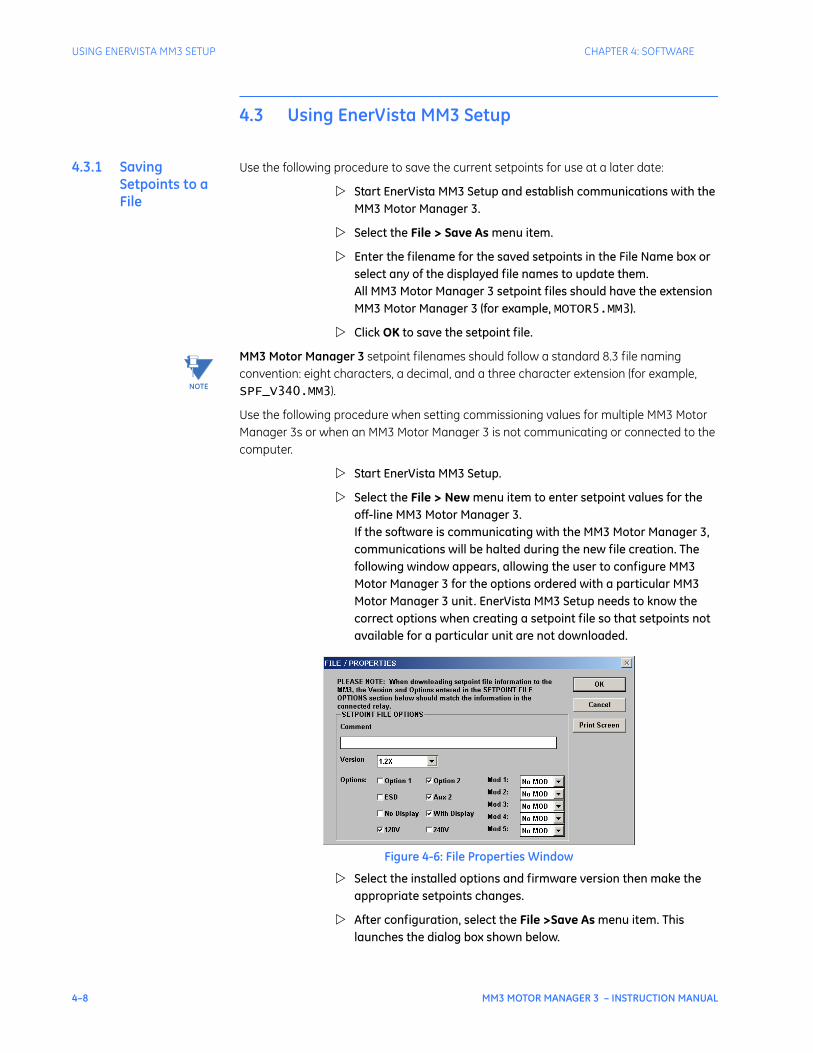
4–8 MM3 MOTOR MANAGER 3 – INSTRUCTION MANUAL
USING ENERVISTA MM3 SETUP CHAPTER 4: SOFTWARE
4.3 Using EnerVista MM3 Setup
4.3.1 Saving Setpoints to a File
Use the following procedure to save the current setpoints for use at a later date:
Start EnerVista MM3 Setup and establish communications with the MM3 Motor Manager 3.
Select the File > Save As menu item.
Enter the filename for the saved setpoints in the File Name box or select any of the displayed file names to update them. All MM3 Motor Manager 3 setpoint files should have the extension MM3 Motor Manager 3 (for example, MOTOR5.MM3).
Click OK to save the setpoint file.
MM3 Motor Manager 3 setpoint filenames should follow a standard 8.3 file naming convention: eight characters, a decimal, and a three character extension (for example, SPF_V340.MM3).
Use the following procedure when setting commissioning values for multiple MM3 Motor Manager 3s or when an MM3 Motor Manager 3 is not communicating or connected to the computer.
Start EnerVista MM3 Setup.
Select the File > New menu item to enter setpoint values for the off-line MM3 Motor Manager 3. If the software is communicating with the MM3 Motor Manager 3, communications will be halted during the new file creation. The following window appears, allowing the user to configure MM3 Motor Manager 3 for the options ordered with a particular MM3 Motor Manager 3 unit. EnerVista MM3 Setup needs to know the correct options when creating a setpoint file so that setpoints not available for a particular unit are not downloaded.
Figure 4-6: File Properties Window
Select the installed options and firmware version then make the appropriate setpoints changes.
After configuration, select the File >Save As menu item. This launches the dialog box shown below.
NOTE
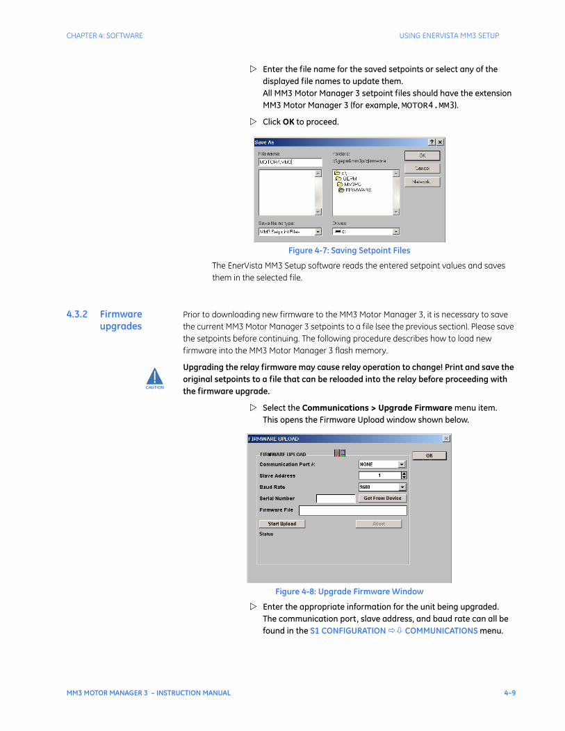
CHAPTER 4: SOFTWARE USING ENERVISTA MM3 SETUP
MM3 MOTOR MANAGER 3 – INSTRUCTION MANUAL 4–9
Enter the file name for the saved setpoints or select any of the displayed file names to update them. All MM3 Motor Manager 3 setpoint files should have the extension MM3 Motor Manager 3 (for example, MOTOR4.MM3).
Click OK to proceed.
Figure 4-7: Saving Setpoint Files
The EnerVista MM3 Setup software reads the entered setpoint values and saves them in the selected file.
4.3.2 Firmware upgrades
Prior to downloading new firmware to the MM3 Motor Manager 3, it is necessary to save the current MM3 Motor Manager 3 setpoints to a file (see the previous section). Please save the setpoints before continuing. The following procedure describes how to load new firmware into the MM3 Motor Manager 3 flash memory.
Upgrading the relay firmware may cause relay operation to change! Print and save the original setpoints to a file that can be reloaded into the relay before proceeding with the firmware upgrade.
Select the Communications > Upgrade Firmware menu item. This opens the Firmware Upload window shown below.
Figure 4-8: Upgrade Firmware Window
Enter the appropriate information for the unit being upgraded. The communication port, slave address, and baud rate can all be found in the S1 CONFIGURATION COMMUNICATIONS menu.
CAUTION
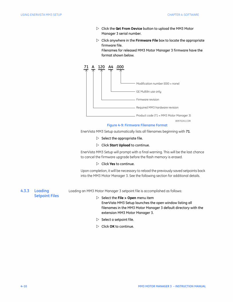
4–10 MM3 MOTOR MANAGER 3 – INSTRUCTION MANUAL
USING ENERVISTA MM3 SETUP CHAPTER 4: SOFTWARE
Click the Get From Device button to upload the MM3 Motor Manager 3 serial number.
Click anywhere in the Firmware File box to locate the appropriate firmware file. Filenames for released MM3 Motor Manager 3 firmware have the format shown below.
Figure 4-9: Firmware Filename Format
EnerVista MM3 Setup automatically lists all filenames beginning with 71.
Select the appropriate file.
Click Start Upload to continue.
EnerVista MM3 Setup will prompt with a final warning. This will be the last chance to cancel the firmware upgrade before the flash memory is erased.
Click Yes to continue.
Upon completion, it will be necessary to reload the previously saved setpoints back into the MM3 Motor Manager 3. See the following section for additional details.
4.3.3 Loading Setpoint Files
Loading an MM3 Motor Manager 3 setpoint file is accomplished as follows:
Select the File > Open menu itemEnerVista MM3 Setup launches the open window listing all filenames in the MM3 Motor Manager 3 default directory with the extension MM3 Motor Manager 3.
Select a setpoint file.
Click OK to continue.
71 A 120 A4 .000
Modification number (000 = none)
GE Multilin use only
Firmware revision
Required MM3 hardware revision
Product code (71 = MM3 Motor Manager 3)
809702A1.CDR
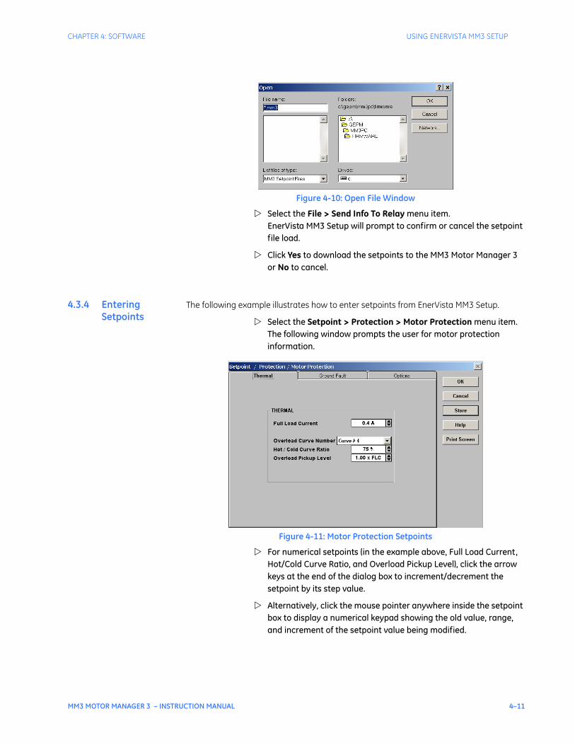
CHAPTER 4: SOFTWARE USING ENERVISTA MM3 SETUP
MM3 MOTOR MANAGER 3 – INSTRUCTION MANUAL 4–11
Figure 4-10: Open File Window
Select the File > Send Info To Relay menu item. EnerVista MM3 Setup will prompt to confirm or cancel the setpoint file load.
Click Yes to download the setpoints to the MM3 Motor Manager 3 or No to cancel.
4.3.4 Entering Setpoints
The following example illustrates how to enter setpoints from EnerVista MM3 Setup.
Select the Setpoint > Protection > Motor Protection menu item.The following window prompts the user for motor protection information.
Figure 4-11: Motor Protection Setpoints
For numerical setpoints (in the example above, Full Load Current, Hot/Cold Curve Ratio, and Overload Pickup Level), click the arrow keys at the end of the dialog box to increment/decrement the setpoint by its step value.
Alternatively, click the mouse pointer anywhere inside the setpoint box to display a numerical keypad showing the old value, range, and increment of the setpoint value being modified.
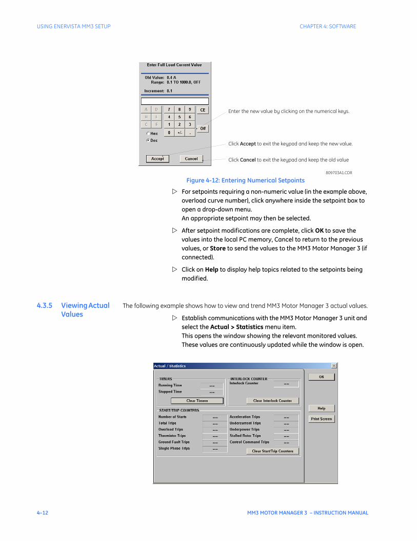
4–12 MM3 MOTOR MANAGER 3 – INSTRUCTION MANUAL
USING ENERVISTA MM3 SETUP CHAPTER 4: SOFTWARE
Figure 4-12: Entering Numerical Setpoints
For setpoints requiring a non-numeric value (in the example above, overload curve number), click anywhere inside the setpoint box to open a drop-down menu. An appropriate setpoint may then be selected.
After setpoint modifications are complete, click OK to save the values into the local PC memory, Cancel to return to the previous values, or Store to send the values to the MM3 Motor Manager 3 (if connected).
Click on Help to display help topics related to the setpoints being modified.
4.3.5 Viewing Actual Values
The following example shows how to view and trend MM3 Motor Manager 3 actual values.
Establish communications with the MM3 Motor Manager 3 unit and select the Actual > Statistics menu item. This opens the window showing the relevant monitored values. These values are continuously updated while the window is open.
Enter the new value by clicking on the numerical keys.
Click to exit the keypad and keep the new value.Accept
Click to exit the keypad and keep the old valueCancel
809703A1.CDR
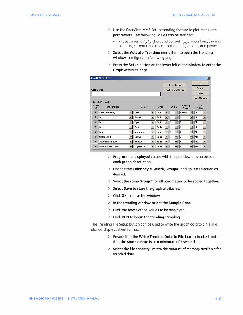
CHAPTER 4: SOFTWARE USING ENERVISTA MM3 SETUP
MM3 MOTOR MANAGER 3 – INSTRUCTION MANUAL 4–13
Use the EnerVista MM3 Setup trending feature to plot measured parameters. The following values can be trended:
• Phase currents (Ia, Ib, Ic), ground current (Ignd), motor load, thermal capacity, current unbalance, analog input, voltage, and power.
Select the Actual > Trending menu item to open the trending window (see figure on following page).
Press the Setup button on the lower left of the window to enter the Graph Attribute page.
Program the displayed values with the pull-down menu beside each graph description.
Change the Color, Style, Width, Group#, and Spline selection as desired.
Select the same Group# for all parameters to be scaled together.
Select Save to store the graph attributes.
Click OK to close the window.
In the trending window, select the Sample Rate.
Click the boxes of the values to be displayed.
Click RUN to begin the trending sampling.
The Trending File Setup button can be used to write the graph data to a file in a standard spreadsheet format.
Ensure that the Write Trended Data to File box is checked and that the Sample Rate is at a minimum of 5 seconds.
Select the file capacity limit to the amount of memory available for trended data.
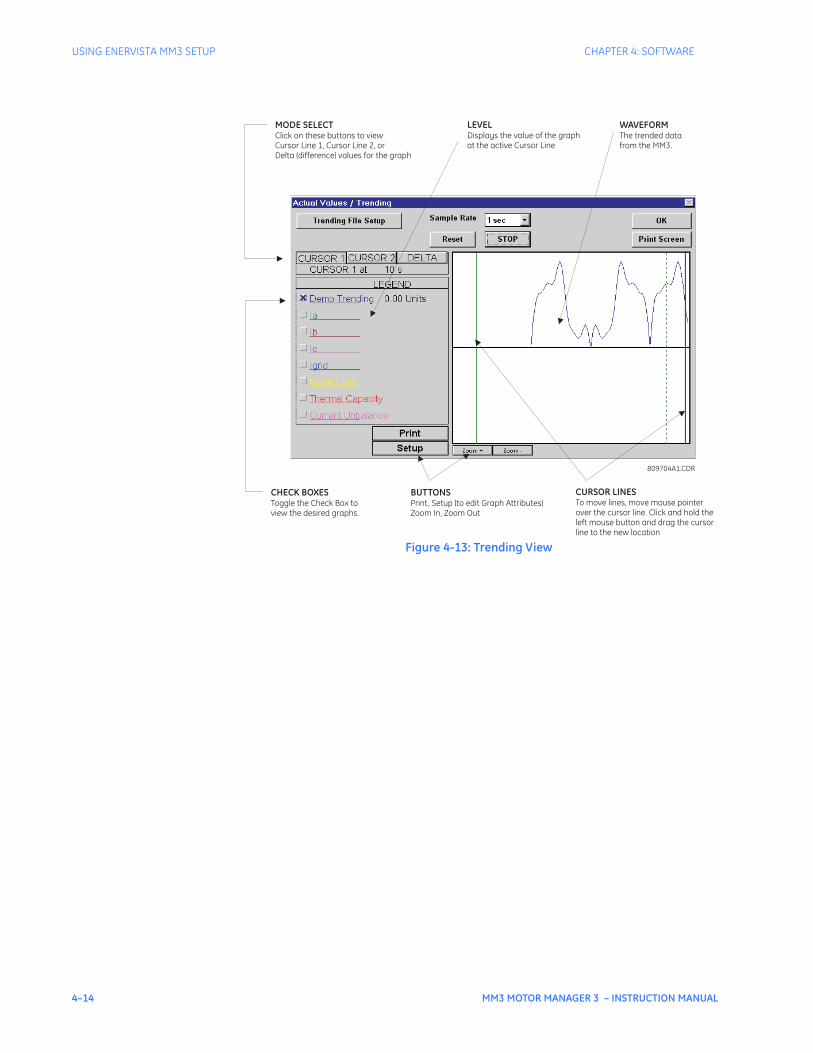
4–14 MM3 MOTOR MANAGER 3 – INSTRUCTION MANUAL
USING ENERVISTA MM3 SETUP CHAPTER 4: SOFTWARE
Figure 4-13: Trending View
809704A1.CDR
CHECK BOXESToggle the Check Box toview the desired graphs.
BUTTONSPrint, Setup (to edit Graph Attributes)Zoom In, Zoom Out
CURSOR LINESTo move lines, move mouse pointerover the cursor line. Click and hold theleft mouse button and drag the cursorline to the new location
MODE SELECTClick on these buttons to viewCursor Line 1, Cursor Line 2, orDelta (difference) values for the graph
LEVELDisplays the value of the graphat the active Cursor Line
WAVEFORMThe trended datafrom the MM3.
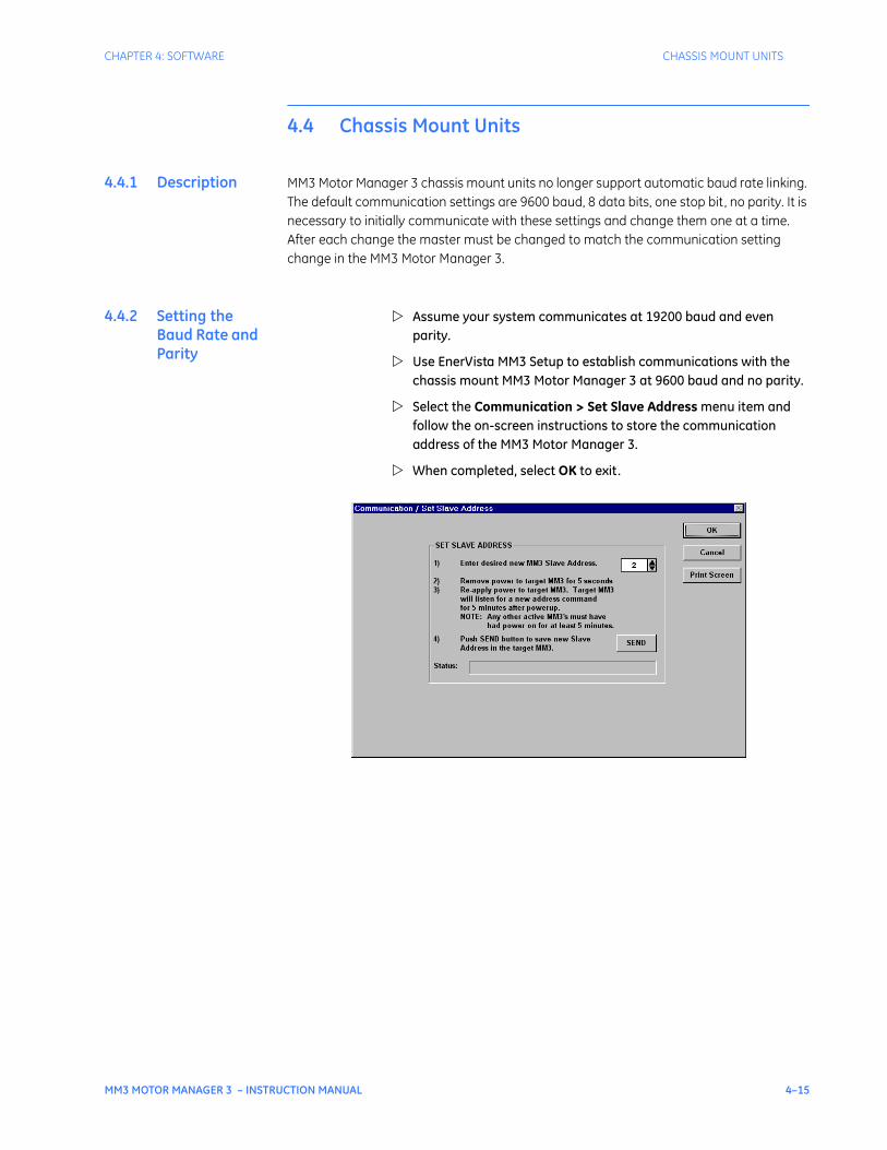
CHAPTER 4: SOFTWARE CHASSIS MOUNT UNITS
MM3 MOTOR MANAGER 3 – INSTRUCTION MANUAL 4–15
4.4 Chassis Mount Units
4.4.1 Description MM3 Motor Manager 3 chassis mount units no longer support automatic baud rate linking. The default communication settings are 9600 baud, 8 data bits, one stop bit, no parity. It is necessary to initially communicate with these settings and change them one at a time. After each change the master must be changed to match the communication setting change in the MM3 Motor Manager 3.
4.4.2 Setting the Baud Rate and Parity
Assume your system communicates at 19200 baud and even parity.
Use EnerVista MM3 Setup to establish communications with the chassis mount MM3 Motor Manager 3 at 9600 baud and no parity.
Select the Communication > Set Slave Address menu item and follow the on-screen instructions to store the communication address of the MM3 Motor Manager 3.
When completed, select OK to exit.
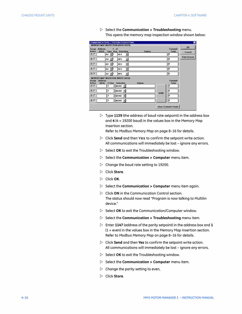
4–16 MM3 MOTOR MANAGER 3 – INSTRUCTION MANUAL
CHASSIS MOUNT UNITS CHAPTER 4: SOFTWARE
Select the Communication > Troubleshooting menu. This opens the memory map inspection window shown below:
Type 1139 (the address of baud rate setpoint) in the address box and 4 (4 = 19200 baud) in the values box in the Memory Map Insertion section. Refer to Modbus Memory Map on page 8–16 for details.
Click Send and then Yes to confirm the setpoint write action. All communications will immediately be lost – ignore any errors.
Select OK to exit the Troubleshooting window.
Select the Communication > Computer menu item.
Change the baud rate setting to 19200.
Click Store.
Click OK.
Select the Communication > Computer menu item again.
Click ON in the Communication Control section. The status should now read “Program is now talking to Multilin device.”
Select OK to exit the Communication/Computer window.
Select the Communication > Troubleshooting menu item.
Enter 1147 (address of the parity setpoint) in the address box and 1 (1 = even) in the values box in the Memory Map Insertion section. Refer to Modbus Memory Map on page 8–16 for details.
Click Send and then Yes to confirm the setpoint write action. All communications will immediately be lost – ignore any errors.
Select OK to exit the Troubleshooting window.
Select the Communication > Computer menu item.
Change the parity setting to even,
Click Store.

CHAPTER 4: SOFTWARE CHASSIS MOUNT UNITS
MM3 MOTOR MANAGER 3 – INSTRUCTION MANUAL 4–17
Click OK.
Select the Communication > Computer menu item again.
Click ON in the Communication Control section. The status should now read “Program is now talking to Multilin device.”
Select OK to exit the Communication/Computer window.

4–18 MM3 MOTOR MANAGER 3 – INSTRUCTION MANUAL
CHASSIS MOUNT UNITS CHAPTER 4: SOFTWARE
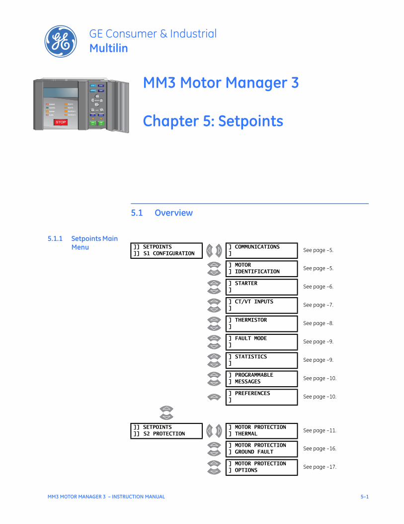
MM3 MOTOR MANAGER 3 – INSTRUCTION MANUAL 5–1
MM3 Motor Manager 3
Chapter 5: Setpoints
GE Consumer & IndustrialMultilin
STOP
RUNNING RELAY ARELAY A
STOPPED RELAY BRELAY B
TRIPPED AUX RELAY 1AUX RELAY 1
ALARM AUX RELAY 2AUX RELAY 2
VALUE
MESSAGE
AUTO MANUAL
STORE
RESET
ACTUAL
SETPOINT
START
A
START
A
START
B
START
B
Setpoints
5.1 Overview
5.1.1 Setpoints Main Menu ]] SETPOINTS
]] S1 CONFIGURATION] COMMUNICATIONS]
See page –5.
] MOTOR] IDENTIFICATION
See page –5.
] STARTER]
See page –6.
] CT/VT INPUTS]
See page –7.
] THERMISTOR]
See page –8.
] FAULT MODE]
See page –9.
] STATISTICS]
See page –9.
] PROGRAMMABLE] MESSAGES
See page –10.
] PREFERENCES]
See page –10.
]] SETPOINTS]] S2 PROTECTION
] MOTOR PROTECTION] THERMAL
See page –11.
] MOTOR PROTECTION] GROUND FAULT
See page –16.
] MOTOR PROTECTION] OPTIONS
See page –17.
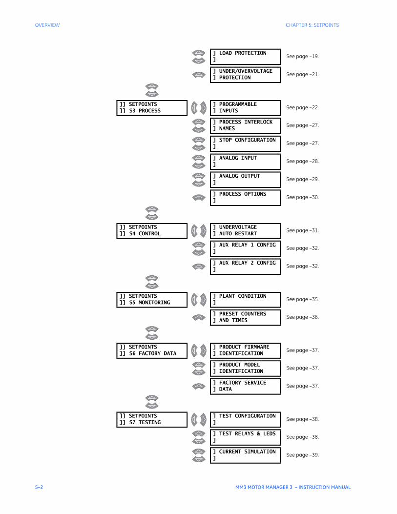
5–2 MM3 MOTOR MANAGER 3 – INSTRUCTION MANUAL
OVERVIEW CHAPTER 5: SETPOINTS
] LOAD PROTECTION]
See page –19.
] UNDER/OVERVOLTAGE] PROTECTION
See page –21.
]] SETPOINTS]] S3 PROCESS
] PROGRAMMABLE] INPUTS
See page –22.
] PROCESS INTERLOCK] NAMES
See page –27.
] STOP CONFIGURATION]
See page –27.
] ANALOG INPUT]
See page –28.
] ANALOG OUTPUT]
See page –29.
] PROCESS OPTIONS]
See page –30.
]] SETPOINTS]] S4 CONTROL
] UNDERVOLTAGE] AUTO RESTART
See page –31.
] AUX RELAY 1 CONFIG]
See page –32.
] AUX RELAY 2 CONFIG]
See page –32.
]] SETPOINTS]] S5 MONITORING
] PLANT CONDITION]
See page –35.
] PRESET COUNTERS] AND TIMES
See page –36.
]] SETPOINTS]] S6 FACTORY DATA
] PRODUCT FIRMWARE] IDENTIFICATION
See page –37.
] PRODUCT MODEL] IDENTIFICATION
See page –37.
] FACTORY SERVICE] DATA
See page –37.
]] SETPOINTS]] S7 TESTING
] TEST CONFIGURATION]
See page –38.
] TEST RELAYS & LEDS]
See page –38.
] CURRENT SIMULATION]
See page –39.
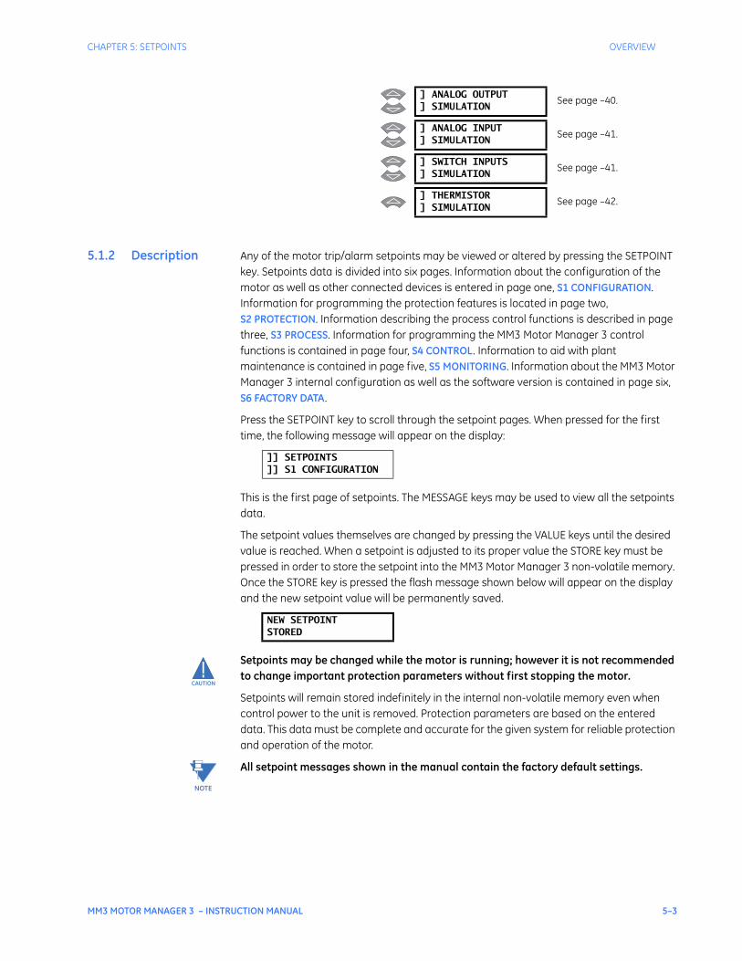
CHAPTER 5: SETPOINTS OVERVIEW
MM3 MOTOR MANAGER 3 – INSTRUCTION MANUAL 5–3
5.1.2 Description Any of the motor trip/alarm setpoints may be viewed or altered by pressing the SETPOINT key. Setpoints data is divided into six pages. Information about the configuration of the motor as well as other connected devices is entered in page one, S1 CONFIGURATION. Information for programming the protection features is located in page two, S2 PROTECTION. Information describing the process control functions is described in page three, S3 PROCESS. Information for programming the MM3 Motor Manager 3 control functions is contained in page four, S4 CONTROL. Information to aid with plant maintenance is contained in page five, S5 MONITORING. Information about the MM3 Motor Manager 3 internal configuration as well as the software version is contained in page six, S6 FACTORY DATA.
Press the SETPOINT key to scroll through the setpoint pages. When pressed for the first time, the following message will appear on the display:
This is the first page of setpoints. The MESSAGE keys may be used to view all the setpoints data.
The setpoint values themselves are changed by pressing the VALUE keys until the desired value is reached. When a setpoint is adjusted to its proper value the STORE key must be pressed in order to store the setpoint into the MM3 Motor Manager 3 non-volatile memory. Once the STORE key is pressed the flash message shown below will appear on the display and the new setpoint value will be permanently saved.
Setpoints may be changed while the motor is running; however it is not recommended to change important protection parameters without first stopping the motor.
Setpoints will remain stored indefinitely in the internal non-volatile memory even when control power to the unit is removed. Protection parameters are based on the entered data. This data must be complete and accurate for the given system for reliable protection and operation of the motor.
All setpoint messages shown in the manual contain the factory default settings.
] ANALOG OUTPUT] SIMULATION
See page –40.
] ANALOG INPUT] SIMULATION
See page –41.
] SWITCH INPUTS] SIMULATION
See page –41.
] THERMISTOR] SIMULATION
See page –42.
]] SETPOINTS]] S1 CONFIGURATION
NEW SETPOINTSTORED
CAUTION
NOTE

5–4 MM3 MOTOR MANAGER 3 – INSTRUCTION MANUAL
OVERVIEW CHAPTER 5: SETPOINTS
5.1.3 Setpoint Message Abbreviations
The following abbreviations are used in the messages in the Setpoints pages:
• A, Amps: amperes
• AUX: auxiliary
• CBCT: core balance current transformer
• COM, Comms: communication
• CT: current transformer
• FLC: full load current
• FV: full voltage
• G/F: ground fault
• GND: ground
• Hz: Hertz
• Kohms: kilo-ohms
• MAX: maximum
• MIN: minimum
• SEC, s: seconds
• UV: undervoltage
• VT: voltage transformer
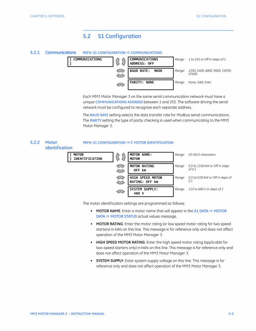
CHAPTER 5: SETPOINTS S1 CONFIGURATION
MM3 MOTOR MANAGER 3 – INSTRUCTION MANUAL 5–5
5.2 S1 Configuration
5.2.1 Communications PATH: S1 CONFIGURATION COMMUNICATIONS
Each MM3 Motor Manager 3 on the same serial communication network must have a unique COMMUNICATIONS ADDRESS between 1 and 255. The software driving the serial network must be configured to recognize each separate address.
The BAUD RATE setting selects the data transfer rate for Modbus serial communications. The PARITY setting the type of parity checking is used when communicating to the MM3 Motor Manager 3.
5.2.2 Motor Identification
PATH: S1 CONFIGURATION MOTOR IDENTIFICATION
The motor identification settings are programmed as follows:
• MOTOR NAME: Enter a motor name that will appear in the A1 DATA MOTOR DATA MOTOR STATUS actual values message.
• MOTOR RATING: Enter the motor rating (or low speed motor rating for two speed starters) in kWs on this line. This message is for reference only and does not affect operation of the MM3 Motor Manager 3.
• HIGH SPEED MOTOR RATING: Enter the high speed motor rating (applicable for two-speed starters only) in kWs on this line. This message is for reference only and does not affect operation of the MM3 Motor Manager 3.
• SYSTEM SUPPLY: Enter system supply voltage on this line. This message is for reference only and does not affect operation of the MM3 Motor Manager 3.
] COMMUNICATIONS]
COMMUNICATIONSADDRESS: OFF
Range: 1 to 255 or Off in steps of 1
BAUD RATE: 9600 Range: 1200, 2400, 4800, 9600, 19200, 57600
PARITY: NONE Range: None, Odd, Even
] MOTOR] IDENTIFICATION
MOTOR NAME:MOTOR
Range: 20 ASCII characters
MOTOR RATINGOFF kW
Range: 0.3 to 1100 kW or Off in steps of 0.1
HIGH SPEED MOTORRATING: OFF kW
Range: 0.3 to1100 kW or Off in steps of 0.1
SYSTEM SUPPLY:480 V
Range: 110 to 690 V in steps of 1
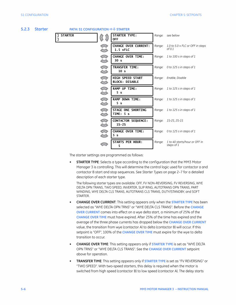
5–6 MM3 MOTOR MANAGER 3 – INSTRUCTION MANUAL
S1 CONFIGURATION CHAPTER 5: SETPOINTS
5.2.3 Starter PATH: S1 CONFIGURATION STARTER
The starter settings are programmed as follows:
• STARTER TYPE: Selects a type according to the configuration that the MM3 Motor Manager 3 is controlling. This will determine the control logic used for contactor a and contactor B start and stop sequences. See Starter Types on page 2–7 for a detailed description of each starter type.
The following starter types are available: OFF, FV NON-REVERSING, FV REVERSING, WYE DELTA OPN TRANS, TWO SPEED, INVERTER, SLIP RING, AUTOTRANS OPN TRANS, PART WINDING, WYE DELTA CLS TRANS, AUTOTRANS CLS TRANS, DUTY/STANDBY, and SOFT STARTER.
• CHANGE OVER CURRENT: This setting appears only when the STARTER TYPE has been selected as “WYE DELTA OPN TRNS” or “WYE DELTA CLS TRANS”. Before the CHANGE OVER CURRENT comes into effect on a wye delta start, a minimum of 25% of the CHANGE OVER TIME must have expired. After 25% of the time has expired and the average of the three phase currents has dropped below the CHANGE OVER CURRENT value, the transition from wye (contactor A) to delta (contactor B) will occur. If this setpoint is “OFF”, 100% of the CHANGE OVER TIME must expire for the wye to delta transition to occur.
• CHANGE OVER TIME: This setting appears only if STARTER TYPE is set as “WYE DELTA OPN TRNS” or “WYE DELTA CLS TRANS”. See the CHANGE OVER CURRENT setpoint above for operation.
• TRANSFER TIME: This setting appears only if STARTER TYPE is set as “FV REVERSING” or “TWO SPEED”. With two-speed starters, this delay is required when the motor is switched from high speed (contactor B) to low speed (contactor A). The delay starts
] STARTER]
STARTER TYPE:OFF
Range: see below
CHANGE OVER CURRENT:1.5 xFLC
Range: 1.0 to 5.0 × FLC or OFF in steps of 0.1
CHANGE OVER TIME:30 s
Range: 1 to 100 s in steps of 1
TRANSFER TIME:10 s
Range: 0 to 125 s in steps of 1
HIGH SPEED STARTBLOCK: DISABLE
Range: Enable, Disable
RAMP UP TIME:5 s
Range: 1 to 125 s in steps of 1
RAMP DOWN TIME:5 s
Range: 1 to 125 s in steps of 1
STAGE ONE SHORTINGTIME: 5 s
Range: 1 to 125 s in steps of 1
CONTACTOR SEQUENCE:1S-2S
Range: 1S-2S, 2S-1S
CHANGE OVER TIME:5 s
Range: 0 to 125 s in steps of 1
STARTS PER HOUR:5
Range: 1 to 40 starts/hour or OFF in steps of 1
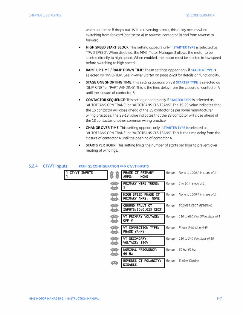
CHAPTER 5: SETPOINTS S1 CONFIGURATION
MM3 MOTOR MANAGER 3 – INSTRUCTION MANUAL 5–7
when contactor B drops out. With a reversing starter, this delay occurs when switching from forward (contactor A) to reverse (contactor B) and from reverse to forward.
• HIGH SPEED START BLOCK: This setting appears only if STARTER TYPE is selected as “TWO SPEED”. When disabled, the MM3 Motor Manager 3 allows the motor to be started directly to high speed. When enabled, the motor must be started in low speed before switching to high speed.
• RAMP UP TIME / RAMP DOWN TIME: These settings appear only if STARTER TYPE is selected as “INVERTER”. See Inverter Starter on page 2–20 for details on functionality.
• STAGE ONE SHORTING TIME: This setting appears only if STARTER TYPE is selected as “SLIP RING” or “PART WINDING”. This is the time delay from the closure of contactor A until the closure of contactor B.
• CONTACTOR SEQUENCE: This setting appears only if STARTER TYPE is selected as “AUTOTRANS OPN TRANS” or “AUTOTRANS CLS TRANS”. The 1S-2S value indicates that the 1S contactor will close ahead of the 2S contactor as per some manufacturer wiring practices. The 2S-1S value indicates that the 2S contactor will close ahead of the 1S contactor, another common wiring practice.
• CHANGE OVER TIME: This setting appears only if STARTER TYPE is selected as “AUTOTRANS OPN TRANS” or “AUTOTRANS CLS TRANS”. This is the time delay from the closure of contactor A until the opening of contactor A.
• STARTS PER HOUR: This setting limits the number of starts per hour to prevent over heating of windings.
5.2.4 CT/VT Inputs PATH: S1 CONFIGURATION CT/VT INPUTS
] CT/VT INPUTS]
PHASE CT PRIMARYAMPS: NONE
Range: None to 1000 A in steps of 1
PRIMARY WIRE TURNS:1
Range: 1 to 10 in steps of 1
HIGH SPEED PHASE CTPRIMARY AMPS: NONE
Range: None to 1000 A in steps of 1
GROUND FAULT CTINPUTS:50:0.025 CBCT
Range: 50:0.025 CBCT, RESIDUAL
VT PRIMARY VOLTAGE:OFF V
Range: 110 to 690 V or Off in steps of 1
VT CONNECTION TYPE:PHASE (A-N)
Range: Phase (A-N), Line (A-B)
VT SECONDARYVOLTAGE: 120V
Range: 110 to 240 V in steps of 10
NOMINAL FREQUENCY:60 Hz
Range: 50 Hz, 60 Hz
REVERSE CT POLARITY:DISABLE
Range: Enable, Disable
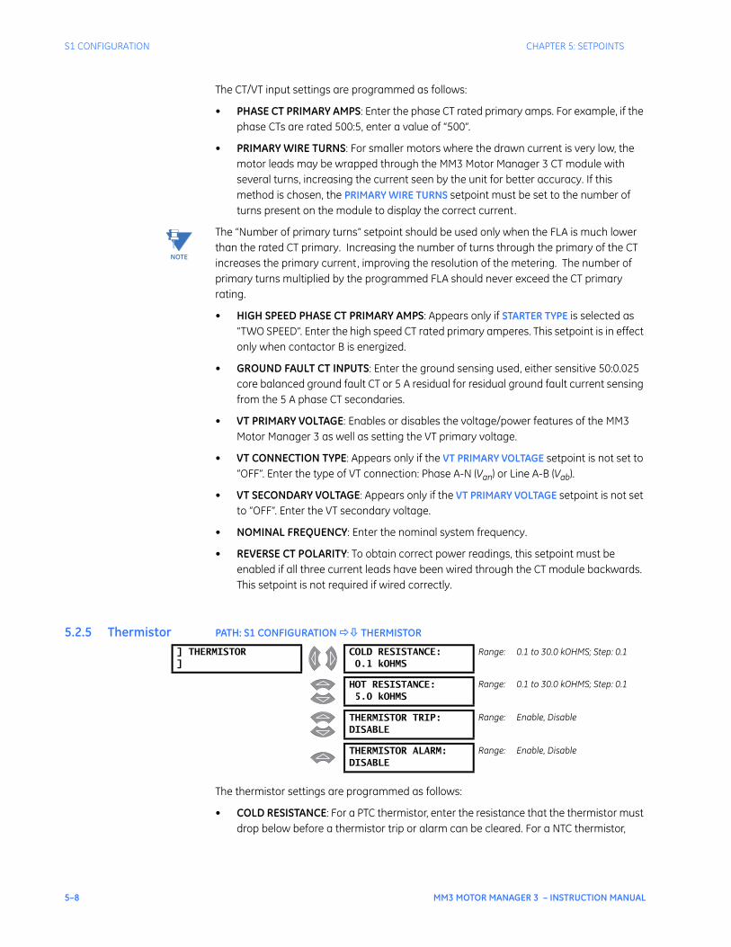
5–8 MM3 MOTOR MANAGER 3 – INSTRUCTION MANUAL
S1 CONFIGURATION CHAPTER 5: SETPOINTS
The CT/VT input settings are programmed as follows:
• PHASE CT PRIMARY AMPS: Enter the phase CT rated primary amps. For example, if the phase CTs are rated 500:5, enter a value of “500”.
• PRIMARY WIRE TURNS: For smaller motors where the drawn current is very low, the motor leads may be wrapped through the MM3 Motor Manager 3 CT module with several turns, increasing the current seen by the unit for better accuracy. If this method is chosen, the PRIMARY WIRE TURNS setpoint must be set to the number of turns present on the module to display the correct current.
The “Number of primary turns” setpoint should be used only when the FLA is much lower than the rated CT primary. Increasing the number of turns through the primary of the CT increases the primary current, improving the resolution of the metering. The number of primary turns multiplied by the programmed FLA should never exceed the CT primary rating.
• HIGH SPEED PHASE CT PRIMARY AMPS: Appears only if STARTER TYPE is selected as “TWO SPEED”. Enter the high speed CT rated primary amperes. This setpoint is in effect only when contactor B is energized.
• GROUND FAULT CT INPUTS: Enter the ground sensing used, either sensitive 50:0.025 core balanced ground fault CT or 5 A residual for residual ground fault current sensing from the 5 A phase CT secondaries.
• VT PRIMARY VOLTAGE: Enables or disables the voltage/power features of the MM3 Motor Manager 3 as well as setting the VT primary voltage.
• VT CONNECTION TYPE: Appears only if the VT PRIMARY VOLTAGE setpoint is not set to “OFF”. Enter the type of VT connection: Phase A-N (Van) or Line A-B (Vab).
• VT SECONDARY VOLTAGE: Appears only if the VT PRIMARY VOLTAGE setpoint is not set to “OFF”. Enter the VT secondary voltage.
• NOMINAL FREQUENCY: Enter the nominal system frequency.
• REVERSE CT POLARITY: To obtain correct power readings, this setpoint must be enabled if all three current leads have been wired through the CT module backwards. This setpoint is not required if wired correctly.
5.2.5 Thermistor PATH: S1 CONFIGURATION THERMISTOR
The thermistor settings are programmed as follows:
• COLD RESISTANCE: For a PTC thermistor, enter the resistance that the thermistor must drop below before a thermistor trip or alarm can be cleared. For a NTC thermistor,
NOTE
] THERMISTOR]
COLD RESISTANCE:0.1 kOHMS
Range: 0.1 to 30.0 kOHMS; Step: 0.1
HOT RESISTANCE:5.0 kOHMS
Range: 0.1 to 30.0 kOHMS; Step: 0.1
THERMISTOR TRIP:DISABLE
Range: Enable, Disable
THERMISTOR ALARM:DISABLE
Range: Enable, Disable
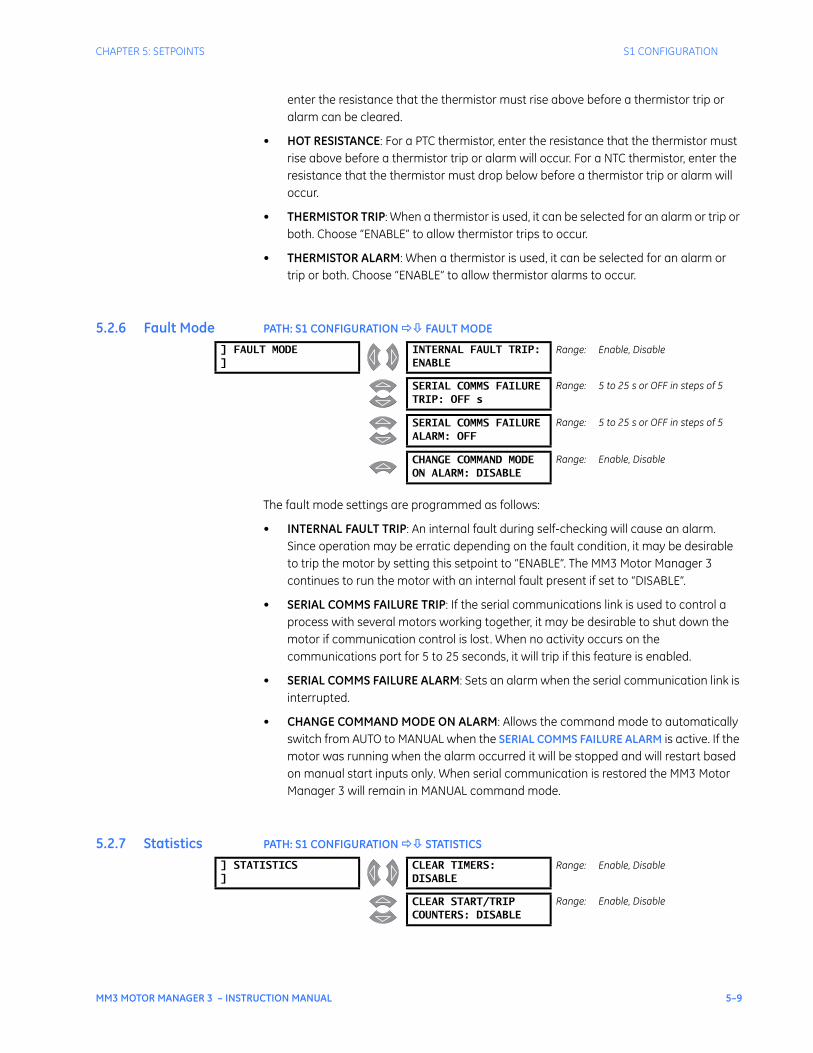
CHAPTER 5: SETPOINTS S1 CONFIGURATION
MM3 MOTOR MANAGER 3 – INSTRUCTION MANUAL 5–9
enter the resistance that the thermistor must rise above before a thermistor trip or alarm can be cleared.
• HOT RESISTANCE: For a PTC thermistor, enter the resistance that the thermistor must rise above before a thermistor trip or alarm will occur. For a NTC thermistor, enter the resistance that the thermistor must drop below before a thermistor trip or alarm will occur.
• THERMISTOR TRIP: When a thermistor is used, it can be selected for an alarm or trip or both. Choose “ENABLE” to allow thermistor trips to occur.
• THERMISTOR ALARM: When a thermistor is used, it can be selected for an alarm or trip or both. Choose “ENABLE” to allow thermistor alarms to occur.
5.2.6 Fault Mode PATH: S1 CONFIGURATION FAULT MODE
The fault mode settings are programmed as follows:
• INTERNAL FAULT TRIP: An internal fault during self-checking will cause an alarm. Since operation may be erratic depending on the fault condition, it may be desirable to trip the motor by setting this setpoint to “ENABLE”. The MM3 Motor Manager 3 continues to run the motor with an internal fault present if set to “DISABLE”.
• SERIAL COMMS FAILURE TRIP: If the serial communications link is used to control a process with several motors working together, it may be desirable to shut down the motor if communication control is lost. When no activity occurs on the communications port for 5 to 25 seconds, it will trip if this feature is enabled.
• SERIAL COMMS FAILURE ALARM: Sets an alarm when the serial communication link is interrupted.
• CHANGE COMMAND MODE ON ALARM: Allows the command mode to automatically switch from AUTO to MANUAL when the SERIAL COMMS FAILURE ALARM is active. If the motor was running when the alarm occurred it will be stopped and will restart based on manual start inputs only. When serial communication is restored the MM3 Motor Manager 3 will remain in MANUAL command mode.
5.2.7 Statistics PATH: S1 CONFIGURATION STATISTICS
] FAULT MODE]
INTERNAL FAULT TRIP:ENABLE
Range: Enable, Disable
SERIAL COMMS FAILURETRIP: OFF s
Range: 5 to 25 s or OFF in steps of 5
SERIAL COMMS FAILUREALARM: OFF
Range: 5 to 25 s or OFF in steps of 5
CHANGE COMMAND MODEON ALARM: DISABLE
Range: Enable, Disable
] STATISTICS]
CLEAR TIMERS:DISABLE
Range: Enable, Disable
CLEAR START/TRIPCOUNTERS: DISABLE
Range: Enable, Disable
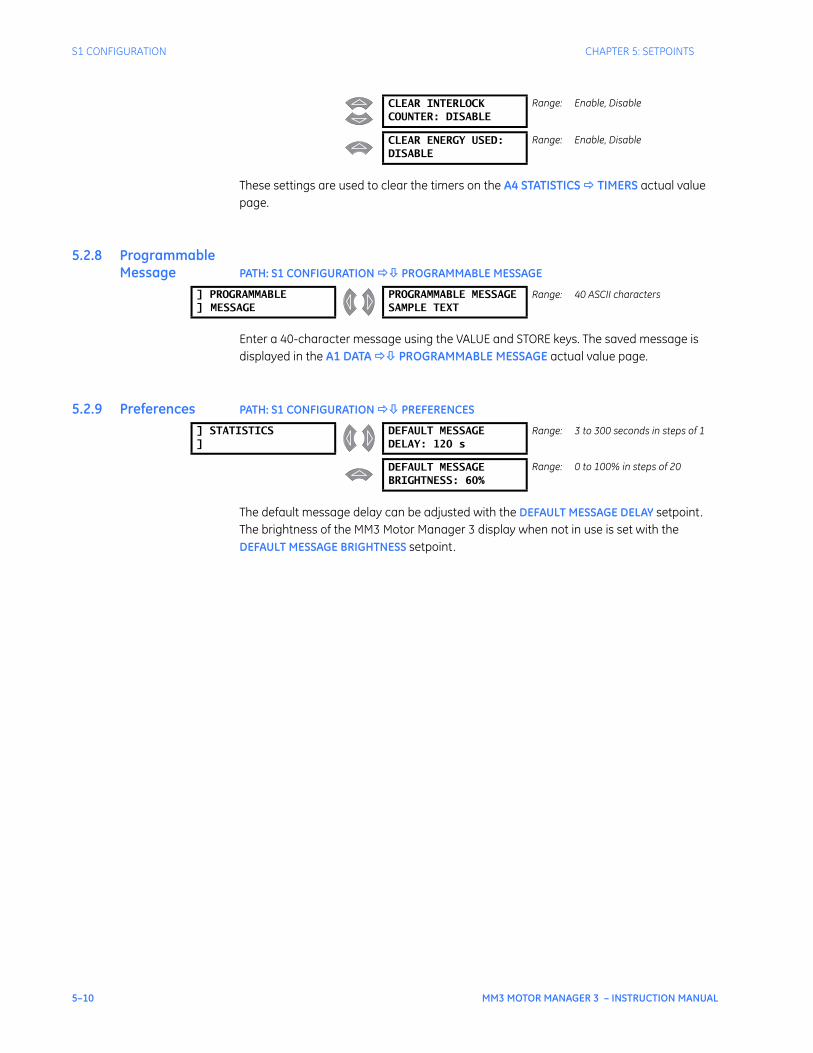
5–10 MM3 MOTOR MANAGER 3 – INSTRUCTION MANUAL
S1 CONFIGURATION CHAPTER 5: SETPOINTS
These settings are used to clear the timers on the A4 STATISTICS TIMERS actual value page.
5.2.8 Programmable Message PATH: S1 CONFIGURATION PROGRAMMABLE MESSAGE
Enter a 40-character message using the VALUE and STORE keys. The saved message is displayed in the A1 DATA PROGRAMMABLE MESSAGE actual value page.
5.2.9 Preferences PATH: S1 CONFIGURATION PREFERENCES
The default message delay can be adjusted with the DEFAULT MESSAGE DELAY setpoint. The brightness of the MM3 Motor Manager 3 display when not in use is set with the DEFAULT MESSAGE BRIGHTNESS setpoint.
CLEAR INTERLOCKCOUNTER: DISABLE
Range: Enable, Disable
CLEAR ENERGY USED:DISABLE
Range: Enable, Disable
] PROGRAMMABLE] MESSAGE
PROGRAMMABLE MESSAGESAMPLE TEXT
Range: 40 ASCII characters
] STATISTICS]
DEFAULT MESSAGEDELAY: 120 s
Range: 3 to 300 seconds in steps of 1
DEFAULT MESSAGEBRIGHTNESS: 60%
Range: 0 to 100% in steps of 20
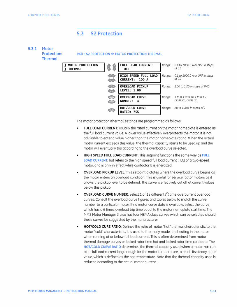
CHAPTER 5: SETPOINTS S2 PROTECTION
MM3 MOTOR MANAGER 3 – INSTRUCTION MANUAL 5–11
5.3 S2 Protection
5.3.1 Motor Protection: Thermal
PATH: S2 PROTECTION MOTOR PROTECTION THERMAL
The motor protection (thermal) settings are programmed as follows:
• FULL LOAD CURRENT: Usually the rated current on the motor nameplate is entered as the full load current value. A lower value effectively overprotects the motor. It is not advisable to enter a value higher than the motor nameplate rating. When the actual motor current exceeds this value, the thermal capacity starts to be used up and the motor will eventually trip according to the overload curve selected.
• HIGH SPEED FULL LOAD CURRENT: This setpoint functions the same way as FULL LOAD CURRENT, but refers to the high speed full load current (FLC) of a two-speed motor, and is only in effect while contactor B is energized.
• OVERLOAD PICKUP LEVEL: This setpoint dictates where the overload curve begins as the motor enters an overload condition. This is useful for service factor motors as it allows the pickup level to be defined. The curve is effectively cut off at current values below this pickup.
• OVERLOAD CURVE NUMBER: Select 1 of 12 different I2t time-overcurrent overload curves. Consult the overload curve figures and tables below to match the curve number to a particular motor. If no motor curve data is available, select the curve which has a 6 times overload trip time equal to the motor nameplate stall time. The MM3 Motor Manager 3 also has four NEMA class curves which can be selected should these curves be suggested by the manufacturer.
• HOT/COLD CURE RATIO: Defines the ratio of motor “hot” thermal characteristic to the motor “cold” characteristic. It is used to thermally model the heating in the motor when running at or below full load current. This is often determined from motor thermal damage curves or locked rotor time hot and locked rotor time cold data. The HOT/COLD CURVE RATIO determines the thermal capacity used when a motor has run at its full load current long enough for the motor temperature to reach its steady state value, which is defined as the hot temperature. Note that the thermal capacity used is reduced according to the actual motor current.
] MOTOR PROTECTION] THERMAL
FULL LOAD CURRENT:OFF
Range: 0.1 to 1000.0 A or OFF in steps of 0.1
HIGH SPEED FULL LOADCURRENT: 100 A
Range: 0.1 to 1000.0 A or OFF in steps of 0.1
OVERLOAD PICKUPLEVEL: 1.00
Range: 1.00 to 1.25 in steps of 0.01
OVERLOAD CURVENUMBER: 4
Range: 1 to 8, Class 10, Class 15, Class 20, Class 30
HOT/COLD CURVERATIO: 75%
Range: 20 to 100% in steps of 1
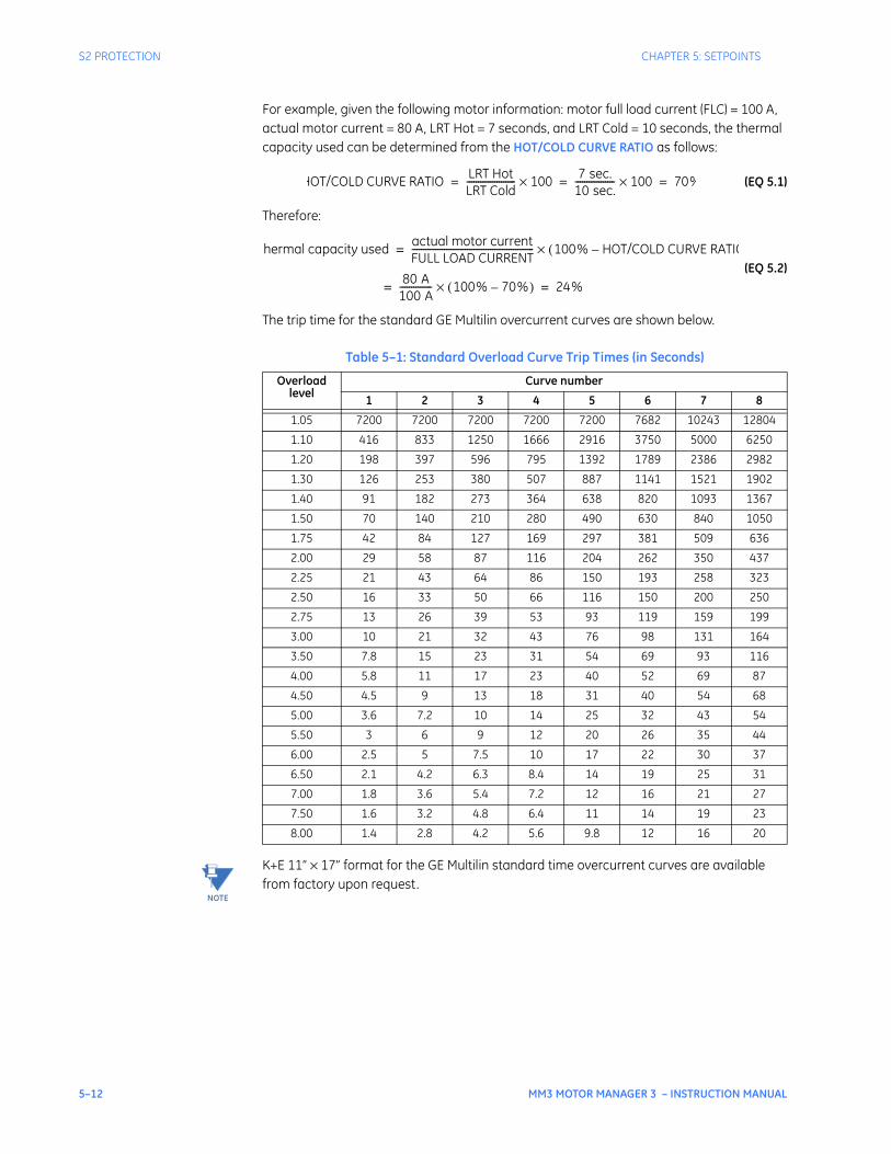
5–12 MM3 MOTOR MANAGER 3 – INSTRUCTION MANUAL
S2 PROTECTION CHAPTER 5: SETPOINTS
For example, given the following motor information: motor full load current (FLC) = 100 A, actual motor current = 80 A, LRT Hot = 7 seconds, and LRT Cold = 10 seconds, the thermal capacity used can be determined from the HOT/COLD CURVE RATIO as follows:
(EQ 5.1)
Therefore:
(EQ 5.2)
The trip time for the standard GE Multilin overcurrent curves are shown below.
K+E 11” × 17” format for the GE Multilin standard time overcurrent curves are available from factory upon request.
Table 5–1: Standard Overload Curve Trip Times (in Seconds)
Overload level
Curve number
1 2 3 4 5 6 7 8
1.05 7200 7200 7200 7200 7200 7682 10243 12804
1.10 416 833 1250 1666 2916 3750 5000 6250
1.20 198 397 596 795 1392 1789 2386 2982
1.30 126 253 380 507 887 1141 1521 1902
1.40 91 182 273 364 638 820 1093 1367
1.50 70 140 210 280 490 630 840 1050
1.75 42 84 127 169 297 381 509 636
2.00 29 58 87 116 204 262 350 437
2.25 21 43 64 86 150 193 258 323
2.50 16 33 50 66 116 150 200 250
2.75 13 26 39 53 93 119 159 199
3.00 10 21 32 43 76 98 131 164
3.50 7.8 15 23 31 54 69 93 116
4.00 5.8 11 17 23 40 52 69 87
4.50 4.5 9 13 18 31 40 54 68
5.00 3.6 7.2 10 14 25 32 43 54
5.50 3 6 9 12 20 26 35 44
6.00 2.5 5 7.5 10 17 22 30 37
6.50 2.1 4.2 6.3 8.4 14 19 25 31
7.00 1.8 3.6 5.4 7.2 12 16 21 27
7.50 1.6 3.2 4.8 6.4 11 14 19 23
8.00 1.4 2.8 4.2 5.6 9.8 12 16 20
HOT/COLD CURVE RATIO LRT HotLRT Cold--------------------- 100× 7 sec.
10 sec.----------------- 100× 70%= = =
hermal capacity used actual motor currentFULL LOAD CURRENT----------------------------------------------------- 100% HOT/COLD CURVE RATIO–(×=
80 A100 A-------------- 100% 70%–( )×= 24%=
NOTE
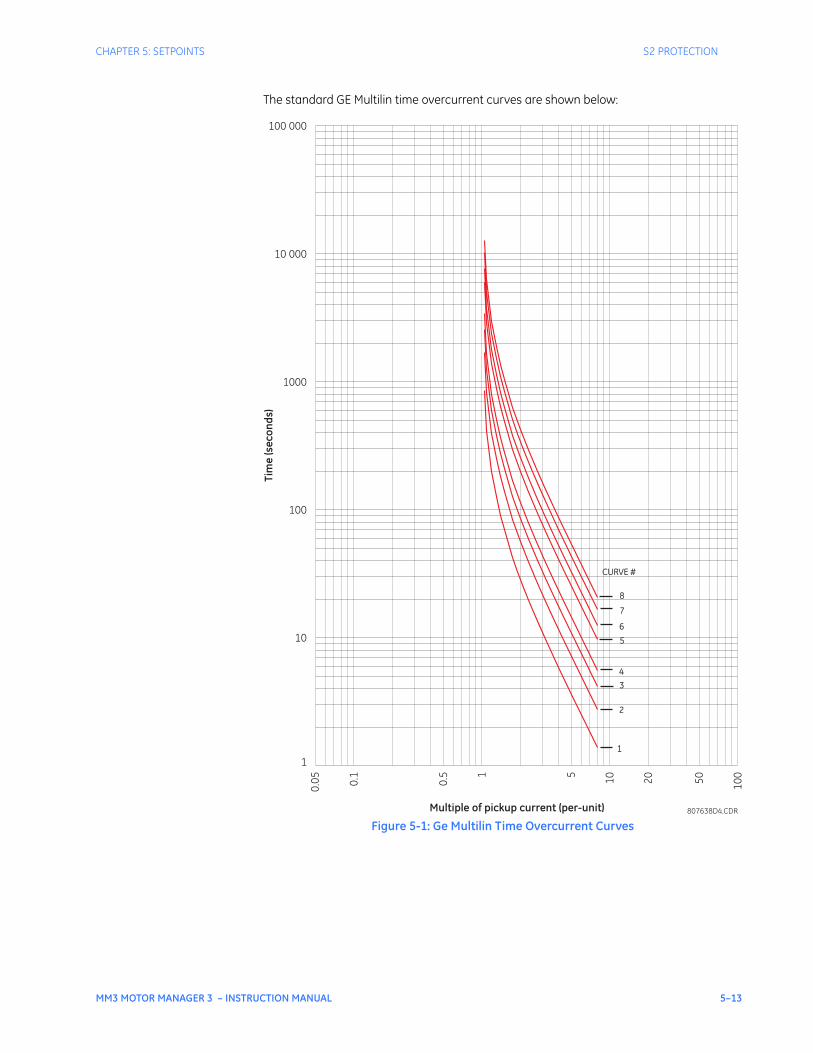
CHAPTER 5: SETPOINTS S2 PROTECTION
MM3 MOTOR MANAGER 3 – INSTRUCTION MANUAL 5–13
The standard GE Multilin time overcurrent curves are shown below:
Figure 5-1: Ge Multilin Time Overcurrent Curves
1
2
3
4
5
6
7
8
CURVE #
807638D4.CDR
1
10
100
1000
Tim
e (s
econ
ds)
10 000
100 000
Multiple of pickup current (per-unit)
0.05 0.
1
0.5 1 5 10 20 50 100
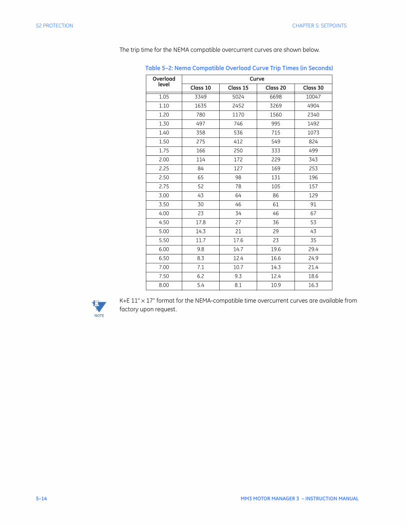
5–14 MM3 MOTOR MANAGER 3 – INSTRUCTION MANUAL
S2 PROTECTION CHAPTER 5: SETPOINTS
The trip time for the NEMA compatible overcurrent curves are shown below.
K+E 11” × 17” format for the NEMA-compatible time overcurrent curves are available from factory upon request.
Table 5–2: Nema Compatible Overload Curve Trip Times (in Seconds)
Overloadlevel
Curve
Class 10 Class 15 Class 20 Class 30
1.05 3349 5024 6698 10047
1.10 1635 2452 3269 4904
1.20 780 1170 1560 2340
1.30 497 746 995 1492
1.40 358 536 715 1073
1.50 275 412 549 824
1.75 166 250 333 499
2.00 114 172 229 343
2.25 84 127 169 253
2.50 65 98 131 196
2.75 52 78 105 157
3.00 43 64 86 129
3.50 30 46 61 91
4.00 23 34 46 67
4.50 17.8 27 36 53
5.00 14.3 21 29 43
5.50 11.7 17.6 23 35
6.00 9.8 14.7 19.6 29.4
6.50 8.3 12.4 16.6 24.9
7.00 7.1 10.7 14.3 21.4
7.50 6.2 9.3 12.4 18.6
8.00 5.4 8.1 10.9 16.3
NOTE
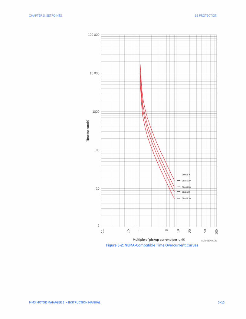
CHAPTER 5: SETPOINTS S2 PROTECTION
MM3 MOTOR MANAGER 3 – INSTRUCTION MANUAL 5–15
Figure 5-2: NEMA-Compatible Time Overcurrent Curves
CLASS 10
CLASS 15
CLASS 20
CLASS 30
CURVE #
807903D4.CDRMultiple of pickup current (per-unit)
0.1
0.5 1 5 10 20 50 100
1
10
100
1000
10 000
100 000
Tim
e (s
econ
ds)
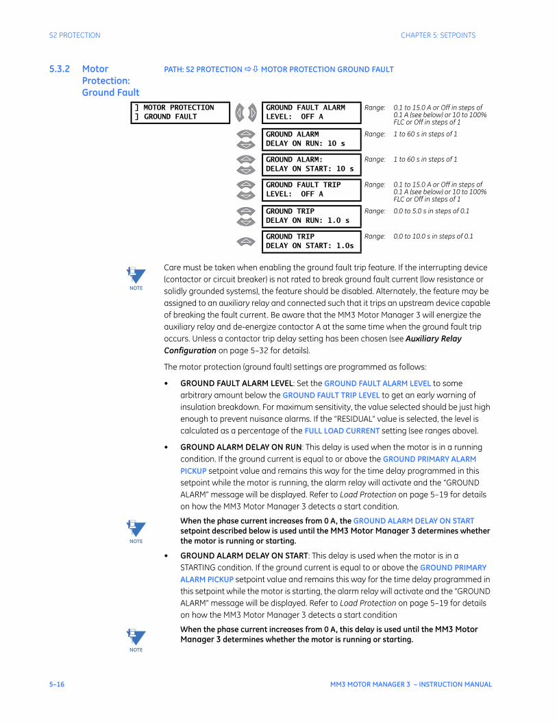
5–16 MM3 MOTOR MANAGER 3 – INSTRUCTION MANUAL
S2 PROTECTION CHAPTER 5: SETPOINTS
5.3.2 Motor Protection: Ground Fault
PATH: S2 PROTECTION MOTOR PROTECTION GROUND FAULT
Care must be taken when enabling the ground fault trip feature. If the interrupting device (contactor or circuit breaker) is not rated to break ground fault current (low resistance or solidly grounded systems), the feature should be disabled. Alternately, the feature may be assigned to an auxiliary relay and connected such that it trips an upstream device capable of breaking the fault current. Be aware that the MM3 Motor Manager 3 will energize the auxiliary relay and de-energize contactor A at the same time when the ground fault trip occurs. Unless a contactor trip delay setting has been chosen (see Auxiliary Relay Configuration on page 5–32 for details).
The motor protection (ground fault) settings are programmed as follows:
• GROUND FAULT ALARM LEVEL: Set the GROUND FAULT ALARM LEVEL to some arbitrary amount below the GROUND FAULT TRIP LEVEL to get an early warning of insulation breakdown. For maximum sensitivity, the value selected should be just high enough to prevent nuisance alarms. If the “RESIDUAL” value is selected, the level is calculated as a percentage of the FULL LOAD CURRENT setting (see ranges above).
• GROUND ALARM DELAY ON RUN: This delay is used when the motor is in a running condition. If the ground current is equal to or above the GROUND PRIMARY ALARM PICKUP setpoint value and remains this way for the time delay programmed in this setpoint while the motor is running, the alarm relay will activate and the “GROUND ALARM” message will be displayed. Refer to Load Protection on page 5–19 for details on how the MM3 Motor Manager 3 detects a start condition.
When the phase current increases from 0 A, the GROUND ALARM DELAY ON START setpoint described below is used until the MM3 Motor Manager 3 determines whether the motor is running or starting.
• GROUND ALARM DELAY ON START: This delay is used when the motor is in a STARTING condition. If the ground current is equal to or above the GROUND PRIMARY ALARM PICKUP setpoint value and remains this way for the time delay programmed in this setpoint while the motor is starting, the alarm relay will activate and the “GROUND ALARM” message will be displayed. Refer to Load Protection on page 5–19 for details on how the MM3 Motor Manager 3 detects a start condition
When the phase current increases from 0 A, this delay is used until the MM3 Motor Manager 3 determines whether the motor is running or starting.
] MOTOR PROTECTION] GROUND FAULT
GROUND FAULT ALARMLEVEL: OFF A
Range: 0.1 to 15.0 A or Off in steps of 0.1 A (see below) or 10 to 100% FLC or Off in steps of 1
GROUND ALARMDELAY ON RUN: 10 s
Range: 1 to 60 s in steps of 1
GROUND ALARM:DELAY ON START: 10 s
Range: 1 to 60 s in steps of 1
GROUND FAULT TRIPLEVEL: OFF A
Range: 0.1 to 15.0 A or Off in steps of 0.1 A (see below) or 10 to 100% FLC or Off in steps of 1
GROUND TRIPDELAY ON RUN: 1.0 s
Range: 0.0 to 5.0 s in steps of 0.1
GROUND TRIPDELAY ON START: 1.0s
Range: 0.0 to 10.0 s in steps of 0.1
NOTE
NOTE
NOTE
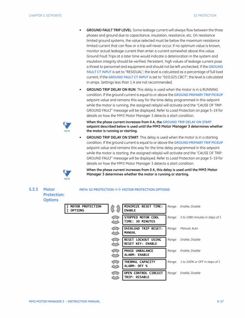
CHAPTER 5: SETPOINTS S2 PROTECTION
MM3 MOTOR MANAGER 3 – INSTRUCTION MANUAL 5–17
• GROUND FAULT TRIP LEVEL: Some leakage current will always flow between the three phases and ground due to capacitance, insulation, resistance, etc. On resistance limited ground systems, the value selected must be below the maximum resistance limited current that can flow or a trip will never occur. If no optimum value is known, monitor actual leakage current then enter a current somewhat above this value. Ground Fault Trips at a later time would indicate a deterioration in the system and insulation integrity should be verified. Persistent, high values of leakage current pose a threat to personnel and equipment and should not be left unchecked. If the GROUND FAULT CT INPUT is set to “RESIDUAL”, the level is calculated as a percentage of full load current; if the GROUND FAULT CT INPUT is set to “50:0.025 CBCT”, the level is calculated in amps. Settings less than 1 A are not recommended.
• GROUND TRIP DELAY ON RUN: This delay is used when the motor is in a RUNNING condition. If the ground current is equal to or above the GROUND PRIMARY TRIP PICKUP setpoint value and remains this way for the time delay programmed in this setpoint while the motor is running, the assigned relay(s) will activate and the “CAUSE OF TRIP: GROUND FAULT” message will be displayed. Refer to Load Protection on page 5–19 for details on how the MM3 Motor Manager 3 detects a start condition.
When the phase current increases from 0 A, the GROUND TRIP DELAY ON START setpoint described below is used until the MM3 Motor Manager 3 determines whether the motor is running or starting.
• GROUND TRIP DELAY ON START: This delay is used when the motor is in a starting condition. If the ground current is equal to or above the GROUND PRIMARY TRIP PICKUP setpoint value and remains this way for the time delay programmed in this setpoint while the motor is starting, the assigned relay(s) will activate and the “CAUSE OF TRIP: GROUND FAULT” message will be displayed. Refer to Load Protection on page 5–19 for details on how the MM3 Motor Manager 3 detects a start condition.
When the phase current increases from 0 A, this delay is used until the MM3 Motor Manager 3 determines whether the motor is running or starting.
5.3.3 Motor Protection: Options
PATH: S2 PROTECTION MOTOR PROTECTION OPTIONS
NOTE
NOTE
] MOTOR PROTECTION] OPTIONS
MINIMIZE RESET TIME:ENABLE
Range: Enable, Disable
STOPPED MOTOR COOLTIME: 30 MINUTES
Range: 5 to 1080 minutes in steps of 1
OVERLOAD TRIP RESET:MANUAL
Range: Manual, Auto
RESET LOCKOUT USINGRESET KEY: ENABLE
Range: Enable, Disable
PHASE UNBALANCEALARM: ENABLE
Range: Enable, Disable
THERMAL CAPACITYALARM: OFF %
Range: 1 to 100% or OFF in steps of 1
OPEN CONTROL CIRCUITTRIP: DISABLE
Range: Enable, Disable
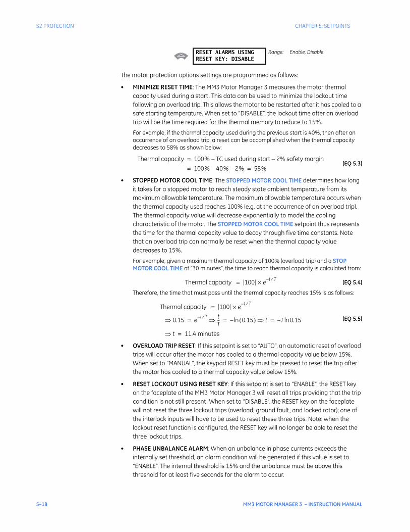
5–18 MM3 MOTOR MANAGER 3 – INSTRUCTION MANUAL
S2 PROTECTION CHAPTER 5: SETPOINTS
The motor protection options settings are programmed as follows:
• MINIMIZE RESET TIME: The MM3 Motor Manager 3 measures the motor thermal capacity used during a start. This data can be used to minimize the lockout time following an overload trip. This allows the motor to be restarted after it has cooled to a safe starting temperature. When set to “DISABLE”, the lockout time after an overload trip will be the time required for the thermal memory to reduce to 15%.
For example, if the thermal capacity used during the previous start is 40%, then after an occurrence of an overload trip, a reset can be accomplished when the thermal capacity decreases to 58% as shown below:
(EQ 5.3)
• STOPPED MOTOR COOL TIME: The STOPPED MOTOR COOL TIME determines how long it takes for a stopped motor to reach steady state ambient temperature from its maximum allowable temperature. The maximum allowable temperature occurs when the thermal capacity used reaches 100% (e.g. at the occurrence of an overload trip). The thermal capacity value will decrease exponentially to model the cooling characteristic of the motor. The STOPPED MOTOR COOL TIME setpoint thus represents the time for the thermal capacity value to decay through five time constants. Note that an overload trip can normally be reset when the thermal capacity value decreases to 15%.
For example, given a maximum thermal capacity of 100% (overload trip) and a STOP MOTOR COOL TIME of “30 minutes”, the time to reach thermal capacity is calculated from:
(EQ 5.4)
Therefore, the time that must pass until the thermal capacity reaches 15% is as follows:
(EQ 5.5)
• OVERLOAD TRIP RESET: If this setpoint is set to “AUTO”, an automatic reset of overload trips will occur after the motor has cooled to a thermal capacity value below 15%. When set to “MANUAL”, the keypad RESET key must be pressed to reset the trip after the motor has cooled to a thermal capacity value below 15%.
• RESET LOCKOUT USING RESET KEY: If this setpoint is set to “ENABLE”, the RESET key on the faceplate of the MM3 Motor Manager 3 will reset all trips providing that the trip condition is not still present. When set to “DISABLE”, the RESET key on the faceplate will not reset the three lockout trips (overload, ground fault, and locked rotor); one of the interlock inputs will have to be used to reset these three trips. Note: when the lockout reset function is configured, the RESET key will no longer be able to reset the three lockout trips.
• PHASE UNBALANCE ALARM: When an unbalance in phase currents exceeds the internally set threshold, an alarm condition will be generated if this value is set to “ENABLE”. The internal threshold is 15% and the unbalance must be above this threshold for at least five seconds for the alarm to occur.
RESET ALARMS USINGRESET KEY: DISABLE
Range: Enable, Disable
Thermal capacity 100% TC used during start– 2% safety margin–=
100% 40%– 2%–= 58%=
Thermal capacity 100 e t T⁄–×=
Thermal capacity 100 e t T⁄–×=
0.15⇒ e t T⁄– tT--⇒ 0.15( )ln– t⇒ T 0.15ln–= = =
t⇒ 11.4 minutes=
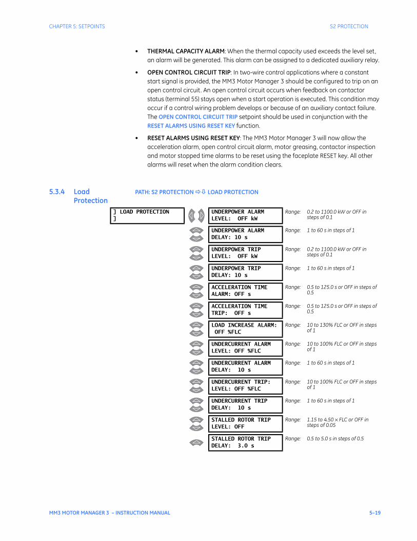
CHAPTER 5: SETPOINTS S2 PROTECTION
MM3 MOTOR MANAGER 3 – INSTRUCTION MANUAL 5–19
• THERMAL CAPACITY ALARM: When the thermal capacity used exceeds the level set, an alarm will be generated. This alarm can be assigned to a dedicated auxiliary relay.
• OPEN CONTROL CIRCUIT TRIP: In two-wire control applications where a constant start signal is provided, the MM3 Motor Manager 3 should be configured to trip on an open control circuit. An open control circuit occurs when feedback on contactor status (terminal 55) stays open when a start operation is executed. This condition may occur if a control wiring problem develops or because of an auxiliary contact failure. The OPEN CONTROL CIRCUIT TRIP setpoint should be used in conjunction with the RESET ALARMS USING RESET KEY function.
• RESET ALARMS USING RESET KEY: The MM3 Motor Manager 3 will now allow the acceleration alarm, open control circuit alarm, motor greasing, contactor inspection and motor stopped time alarms to be reset using the faceplate RESET key. All other alarms will reset when the alarm condition clears.
5.3.4 Load Protection
PATH: S2 PROTECTION LOAD PROTECTION
] LOAD PROTECTION]
UNDERPOWER ALARMLEVEL: OFF kW
Range: 0.2 to 1100.0 kW or OFF in steps of 0.1
UNDERPOWER ALARMDELAY: 10 s
Range: 1 to 60 s in steps of 1
UNDERPOWER TRIPLEVEL: OFF kW
Range: 0.2 to 1100.0 kW or OFF in steps of 0.1
UNDERPOWER TRIPDELAY: 10 s
Range: 1 to 60 s in steps of 1
ACCELERATION TIMEALARM: OFF s
Range: 0.5 to 125.0 s or OFF in steps of 0.5
ACCELERATION TIMETRIP: OFF s
Range: 0.5 to 125.0 s or OFF in steps of 0.5
LOAD INCREASE ALARM:OFF %FLC
Range: 10 to 130% FLC or OFF in steps of 1
UNDERCURRENT ALARMLEVEL: OFF %FLC
Range: 10 to 100% FLC or OFF in steps of 1
UNDERCURRENT ALARMDELAY: 10 s
Range: 1 to 60 s in steps of 1
UNDERCURRENT TRIP:LEVEL: OFF %FLC
Range: 10 to 100% FLC or OFF in steps of 1
UNDERCURRENT TRIPDELAY: 10 s
Range: 1 to 60 s in steps of 1
STALLED ROTOR TRIPLEVEL: OFF
Range: 1.15 to 4.50 × FLC or OFF in steps of 0.05
STALLED ROTOR TRIPDELAY: 3.0 s
Range: 0.5 to 5.0 s in steps of 0.5
5–20 MM3 MOTOR MANAGER 3 – INSTRUCTION MANUAL
S2 PROTECTION CHAPTER 5: SETPOINTS
The load protection settings are programmed as follows:
• UNDERPOWER ALARM LEVEL: Appears if VT PRIMARY VOLTAGE is not “OFF”. This feature functions the same as the underpower trip feature but produces an alarm indication instead of a trip.
• UNDERPOWER ALARM DELAY: Appears if VT PRIMARY VOLTAGE and UNDERPOWER ALARM LEVEL are not “OFF”. Enter a delay for activation of the underpower alarm.
• UNDERPOWER TRIP LEVEL: Appears if VT PRIMARY VOLTAGE is not “OFF”. For applications such as pumps, the underpower trip feature or the undercurrent trip feature can be selected to detect loss of load. The advantage of the underpower trip feature is that it allows for more accurate sensing if the loss of load results in only a small change in current and a power factor shift. If the power remains below this value while the motor is running for the time specified in the UNDERPOWER TRIP DELAY, the MM3 Motor Manager 3 will trip. Set this value to “OFF” if no underpower trip is required.
• UNDERPOWER TRIP DELAY: Appears if VT PRIMARY VOLTAGE and UNDERPOWER TRIP LEVEL are not “OFF”. Set the UNDERPOWER TRIP DELAY long enough to prevent nuisance trips from momentary power dips.
• ACCELERATION TIME ALARM: Enter a time longer than the actual acceleration time of the motor. This is defined as the length of time required for the average motor current to drop below full load current after a start command.
• ACCELERATION TIME TRIP: Enter the maximum allowable acceleration time of the motor. This is defined as the length of time required for the average motor current to drop below full load current after a start command.
• LOAD INCREASE ALARM: Set to a suitable level if a warning is required when motor current is approaching, or in, an overload condition. When current exceeds this value, a load increase alarm will occur. Set to “OFF” if not required.
• UNDERCURRENT ALARM LEVEL: This feature functions the same as the undercurrent trip feature but produces an alarm indication instead of a trip.
• UNDERCURRENT ALARM DELAY: Enter the delay for activation of the undercurrent alarm.
• UNDERCURRENT TRIP LEVEL: An undercurrent trip can be selected for applications such as pumps. If the current remains below this value while the motor is running for the time specified in the UNDERCURRENT TRIP DELAY, the MM3 Motor Manager 3 will trip. Set this value to “OFF” if no undercurrent trip is required.
• STALLED ROTOR TRIP LEVEL: Mechanical equipment such as pumps or fans can be quickly damaged by jams, resulting in a locked rotor stall. Even though the motor may be able to withstand the locked rotor for a long time, it may be desirable to trip the motor as soon as the stall condition occurs. The MM3 Motor Manager 3 will trip when the running current exceeds this value after the stalled rotor time. Set this value to “OFF” if stall protection of driven equipment is not required since the thermal overload protection will protect the motor. This feature is defeated during the inrush of motor starting.
• STALLED ROTOR TRIP DELAY: If the STALLED ROTOR TRIP LEVEL is set to a value other than “OFF”, the MM3 Motor Manager 3 will trip after the time specified by this setpoint.
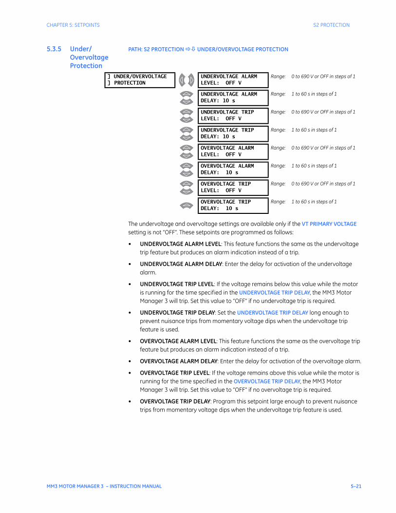
CHAPTER 5: SETPOINTS S2 PROTECTION
MM3 MOTOR MANAGER 3 – INSTRUCTION MANUAL 5–21
5.3.5 Under/Overvoltage Protection
PATH: S2 PROTECTION UNDER/OVERVOLTAGE PROTECTION
The undervoltage and overvoltage settings are available only if the VT PRIMARY VOLTAGE setting is not “OFF”. These setpoints are programmed as follows:
• UNDERVOLTAGE ALARM LEVEL: This feature functions the same as the undervoltage trip feature but produces an alarm indication instead of a trip.
• UNDERVOLTAGE ALARM DELAY: Enter the delay for activation of the undervoltage alarm.
• UNDERVOLTAGE TRIP LEVEL: If the voltage remains below this value while the motor is running for the time specified in the UNDERVOLTAGE TRIP DELAY, the MM3 Motor Manager 3 will trip. Set this value to “OFF” if no undervoltage trip is required.
• UNDERVOLTAGE TRIP DELAY: Set the UNDERVOLTAGE TRIP DELAY long enough to prevent nuisance trips from momentary voltage dips when the undervoltage trip feature is used.
• OVERVOLTAGE ALARM LEVEL: This feature functions the same as the overvoltage trip feature but produces an alarm indication instead of a trip.
• OVERVOLTAGE ALARM DELAY: Enter the delay for activation of the overvoltage alarm.
• OVERVOLTAGE TRIP LEVEL: If the voltage remains above this value while the motor is running for the time specified in the OVERVOLTAGE TRIP DELAY, the MM3 Motor Manager 3 will trip. Set this value to “OFF” if no overvoltage trip is required.
• OVERVOLTAGE TRIP DELAY: Program this setpoint large enough to prevent nuisance trips from momentary voltage dips when the undervoltage trip feature is used.
] UNDER/OVERVOLTAGE] PROTECTION
UNDERVOLTAGE ALARMLEVEL: OFF V
Range: 0 to 690 V or OFF in steps of 1
UNDERVOLTAGE ALARMDELAY: 10 s
Range: 1 to 60 s in steps of 1
UNDERVOLTAGE TRIPLEVEL: OFF V
Range: 0 to 690 V or OFF in steps of 1
UNDERVOLTAGE TRIPDELAY: 10 s
Range: 1 to 60 s in steps of 1
OVERVOLTAGE ALARMLEVEL: OFF V
Range: 0 to 690 V or OFF in steps of 1
OVERVOLTAGE ALARMDELAY: 10 s
Range: 1 to 60 s in steps of 1
OVERVOLTAGE TRIPLEVEL: OFF V
Range: 0 to 690 V or OFF in steps of 1
OVERVOLTAGE TRIPDELAY: 10 s
Range: 1 to 60 s in steps of 1
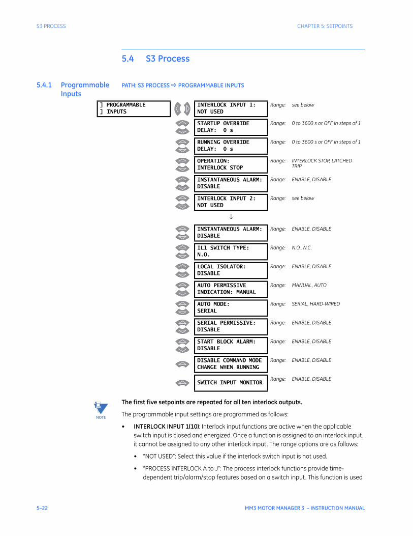
5–22 MM3 MOTOR MANAGER 3 – INSTRUCTION MANUAL
S3 PROCESS CHAPTER 5: SETPOINTS
5.4 S3 Process
5.4.1 Programmable Inputs
PATH: S3 PROCESS PROGRAMMABLE INPUTS
The first five setpoints are repeated for all ten interlock outputs.
The programmable input settings are programmed as follows:
• INTERLOCK INPUT 1(10): Interlock input functions are active when the applicable switch input is closed and energized. Once a function is assigned to an interlock input, it cannot be assigned to any other interlock input. The range options are as follows:
• “NOT USED”: Select this value if the interlock switch input is not used.
• “PROCESS INTERLOCK A to J”: The process interlock functions provide time-dependent trip/alarm/stop features based on a switch input. This function is used
] PROGRAMMABLE] INPUTS
INTERLOCK INPUT 1:NOT USED
Range: see below
STARTUP OVERRIDEDELAY: 0 s
Range: 0 to 3600 s or OFF in steps of 1
RUNNING OVERRIDEDELAY: 0 s
Range: 0 to 3600 s or OFF in steps of 1
OPERATION:INTERLOCK STOP
Range: INTERLOCK STOP, LATCHED TRIP
INSTANTANEOUS ALARM:DISABLE
Range: ENABLE, DISABLE
INTERLOCK INPUT 2:NOT USED
Range: see below
↓
INSTANTANEOUS ALARM:DISABLE
Range: ENABLE, DISABLE
IL1 SWITCH TYPE:N.O.
Range: N.O., N.C.
LOCAL ISOLATOR:DISABLE
Range: ENABLE, DISABLE
AUTO PERMISSIVEINDICATION: MANUAL
Range: MANUAL, AUTO
AUTO MODE:SERIAL
Range: SERIAL, HARD-WIRED
SERIAL PERMISSIVE:DISABLE
Range: ENABLE, DISABLE
START BLOCK ALARM:DISABLE
Range: ENABLE, DISABLE
DISABLE COMMAND MODE CHANGE WHEN RUNNING
Range: ENABLE, DISABLE
SWITCH INPUT MONITORRange: ENABLE, DISABLE
NOTE

CHAPTER 5: SETPOINTS S3 PROCESS
MM3 MOTOR MANAGER 3 – INSTRUCTION MANUAL 5–23
together with the STARTUP OVERRIDE DELAY, RUNNING OVERRIDE DELAY, OPERATION, and INSTANTANEOUS ALARM setpoints. The names of the process interlock features can be changed to any 20-character alphanumeric sequence. See Interlock Names on page 5–27 for details.
• “PLANT INTERLOCK”: This function provides a switch input trip feature similar to the local isolator. When this switch is unhealthy, a plant interlock trip will occur. The plant interlock trip is automatically cleared when the plant interlock switch goes healthy.
• “LOCKOUT RESET”: This function provides a separate reset facility for lockout trips (i.e. overload, ground fault and stalled rotor). These trips are considered to be more serious than other MM3 Motor Manager 3 trips. When used, this switch will reset overload trips (regardless of lockout time), ground fault trips and stalled rotor trips only. All other trips must be reset using the RESET key. Note that the setpoint in S2 PROTECTION MOTOR PROTECTION OPTIONS RESET LOCKOUT USING RESET setpoint allows lockout trips to be reset using the RESET key if required.
• “SETPOINT ACCESS”: This function provides security against unauthorized changing of MM3 Motor Manager 3 setpoints. When this switch is unhealthy, setpoints cannot be changed from the keypad; when this switch is healthy, setpoints can be changed from the keypad. If this feature is not used then setpoints can always be changed from the keypad.
• “AUTO PERMISSIVE”: This function is used together with the “AUTO START A/B” functions and can be further defined using the AUTO PERMISSIVE INDICATION and AUTO MODE setpoints. If the auto permissive switch is healthy, start commands can come from the Auto Start A / Auto Start B switches. When the auto permissive switch is unhealthy, the Auto Start A / Auto Start B switches are ignored. When the auto permissive switch is healthy, start commands via the Start A and B switch inputs and the faceplate are blocked. See the AUTO PERMISSIVE INDICATION and AUTO MODE setpoint descriptions for further functionality.
• “AUTO START A”: This function is used in conjunction with the “AUTO PERMISSIVE” function described above. When the auto permissive switch is healthy, the Auto Start A switch can be used to start the motor.
• “AUTO START B”: This function is used together with the “AUTO PERMISSIVE” function. When the auto permissive switch is healthy, the Auto Start B switch can be used to start the motor in applications where Start B is used (two-speed and reversing starter types).
• “RESET EMERGENCY STOP TRIP”: This function is used when a separate emergency stop trip reset switch is required. When this switch is healthy and an emergency stop trip is present, the trip will be reset.
• “RESET UNDERCURRENT TRIP”: This function is used when a separate undercurrent trip reset switch is required. When this switch is healthy and an undercurrent trip is present, the trip will be reset.
• “TWO WIRE CONTROL”: This function is used to provide a means to switch from normal pulsed three-wire start/stop control to maintained two-wire start/stop control. When this switch is healthy, start commands (Start A/B switch inputs; Auto Start A/B switch inputs) must be maintained in the closed state for the MM3 Motor Manager 3 to keep the motor running. When the start input is opened, the MM3

5–24 MM3 MOTOR MANAGER 3 – INSTRUCTION MANUAL
S3 PROCESS CHAPTER 5: SETPOINTS
Motor Manager 3 sees this as a stop command and both contactor outputs will open. This is useful in applications with limit switches, PLC control or hand/off/auto (HOA) control.
• “TEST SWITCH”: This function is used to create a test switch facility. When the test switch input is healthy statistical counters (see Counters on page 6–13) are not incremented with the exception of the interlock counter. This is used when control tests on the contactor are being performed and counters should not be updated. If the motor is running when this switch is put into the healthy position, both contactors will open.
• “REMOTE PERMISSIVE”: This function provides a means to interlock between the keypad START A/B keys and the Start A/B switch inputs. When a remote permissive switch is not used both of these start command sources will operate when the MM3 Motor Manager 3 is in manual mode (Manual LED on). When the remote permissive switch is healthy, the Start A/B switch inputs are functional but the START A/B keys are disabled. When the remote permissive switch is unhealthy, the START A/B keys are functional but the Start A/B switch inputs are disabled. Auto mode or hard-wired auto mode (Auto LED on) disables both the Start A/B switches and the START A/B keys.
• “COMMUNICATION SELECT”: This function provides a facility to override the keypad AUTO / MANUAL keys. When this switch is healthy, the MM3 Motor Manager 3 is forced into auto-serial mode (Auto LED on). When this switch is unhealthy, the MM3 Motor Manager 3 reverts back to the mode present before the switch was closed (manual mode, Manual LED on; hard-wired auto mode, Auto LED on).
• “INTERLOCK COUNTER”: This function provides a means to count switch closures when assigned to one of the programmable switch inputs. When the switch input is put into the healthy position, the counter will increment by one (see Counters on page 6–13). See Interlock Names on page 5–27 for details on programming the interlock counter name and units. The digital input coming into the MM3 Motor Manager 3 must have an ON time no less than 100 ms and an OFF time no less than 100 ms. This means that the MM3 Motor Manager 3 can count up to 5 pulses per second = 5 Hz. The counter will count up to 65535 and then roll over. The counter can be cleared with the S1 CONFIGURATION STATISTICS CLEAR INTERLOCK COUNTER setpoint or via the serial communications link.
• “AUX RELAY 1 INHIBIT”: This function will override/inhibit auxiliary relay 1. When healthy, it will prevent auxiliary relay 1 from turning on, or turn off auxiliary relay 1 after it is already on.
• “WYE-DELTA 1M CONTACT” and “WYE-DELTA 2S CONTACT”: These functions are used as status feedback inputs for the wye-delta closed transition starter type. See Wye-delta Closed Transition Starter on page 2–32 for details.
• “U/V RESTART INHIBIT”: This function disables the undervoltage restart feature when the switch is in the healthy position and allows undervoltage restarts to take place when the switch is unhealthy. Note that the undervoltage restart feature must be activated for this interlock function to have any effect.
• “AUTO TRANS 2S CONTACT”: This function is used as a status feedback input for the autotransformer open/closed transition starter type. See Autotransformer Open Transition Starter on page 2–21 and Autotransformer Closed Transition Starter on page 2–25.

CHAPTER 5: SETPOINTS S3 PROCESS
MM3 MOTOR MANAGER 3 – INSTRUCTION MANUAL 5–25
• “STOP A” and “STOP B”: These functions are used for end-of-travel applications. When an interlock configured for STOP A/B opens the corresponding output relay will open. When the STOP A/B input is open the motor cannot be started using start A/B commands or switch inputs.
• “REMOTE RESET”: This function replaces the faceplate RESET key. When this function is used, the faceplate RESET key will not reset any trips. When other switch inputs are used to reset specific trips, the remote reset switch input will not reset those trips (i.e. undercurrent trip, emergency stop trip, lockout trips).
• “MOTOR SELECTOR A/B”: This function is used in conjunction with the duty/standby starter type. In manual mode, the state of this interlock determines which of the two motors is used for starting (healthy = motor B). When A is selected, only the contactor A output relay will respond to start commands. When B is selected, only the contactor B output relay will respond to start commands.
• “DUTY SELECT MAN/AUTO”: This function is used in conjunction with the duty/standby starter type. This input determines the mode of operation for the duty/standby starter (manual or auto). In auto mode, the MM3 Motor Manager 3 will alternatively start motor A and motor B. When the number of starts is an even number, motor A will be started the next time a start command is issued. When the number of starts is odd, motor B will be started the next time a start command is issued. In the event of a trip on either motor, the motor that tripped will be prevented from starting until reset is pressed. All starts will default to the untripped motor. When the trip occurs the MM3 Motor Manager 3 automatically resets the trip to allow the other motor to be started. The trip message becomes an alarm message which must be reset to allow the tripped motor to start. If the second motor trips the MM3 Motor Manager 3 will remain tripped until reset is pressed. The details of manual mode are described above under “MOTOR SELECTOR A/B” above.
Faceplate stop trips, process stop trips, and ESD stop trips must be manually reset regardless of the duty/standby mode. Local isolator and plant interlock trips reset only when the input is healthy.
• STARTUP OVERRIDE DELAY: These setpoints indicate the time that the process interlock switch can remain open on the occurrence of a motor start. If the switch remains unhealthy for longer than this time, a process interlock trip or process interlock stop will occur. If the STARTUP OVERRIDE DELAY is set to 0, the process interlock switch must be healthy for the MM3 Motor Manager 3 to allow the motor to start. If the STARTUP OVERRIDE DELAY is set to “OFF”, this timer is disabled.
• RUNNING OVERRIDE DELAY: These setpoints indicate the time the process interlock switch can be unhealthy during normal running. If the process interlock switch goes unhealthy after a motor start and remains unhealthy for longer than the RUNNING OVERRIDE DELAY, a process interlock trip or process interlock stop will occur. If the RUNNING OVERRIDE DELAY is “OFF” and the process interlock switch goes unhealthy after the motor has started, no process interlock trip or process interlock stop will occur.
• OPERATION: These setpoints determine whether the process interlock feature is a process interlock trip (reset required in order to restart the motor) or a process interlock stop (no reset required).
• INSTANTANEOUS ALARM: These setpoints create an alarm whenever the process interlock switch is unhealthy; there is no time delay associated with this alarm feature.
NOTE

5–26 MM3 MOTOR MANAGER 3 – INSTRUCTION MANUAL
S3 PROCESS CHAPTER 5: SETPOINTS
• IL1 SWITCH TYPE: This setpoint allows the user to configure the type of switch used for the programmable switch inputs as normally open (N.O.) or normally closed (N.C.). When set to N.O. (factory default), if the switch input is closed, it is in the healthy position; if the switch is open, it is in the unhealthy position. When set to N.C., if the switch input is open, it is in the healthy position; if it is closed, it is in the unhealthy position.
• LOCAL ISOLATOR: The local isolator switch input can be enabled or disabled using this setpoint. When set to “ENABLE”, a local isolator trip will occur whenever the local isolator switch input is open. The trip will automatically reset when the switch input is closed.
• AUTO PERMISSIVE INDICATION: This setpoint determines whether the Auto or Manual LED is illuminated when in the auto permissive mode. This allows the Auto LED to be used for auto permissive and serial control, or just for serial control.
• AUTO MODE: This setpoint can be configured to either ‘SERIAL’ or ‘HARD-WIRED’. When in the ‘SERIAL’ mode and the ‘AUTO’ button is pressed with 'AUTO PERMISSIVE' switch unhealthy, the MM3 will execute start commands from the RS485 serial link only. When in the ‘HARD-WIRED’ mode and the ‘AUTO’ key is pressed, the MM3 will execute start commands from the ‘AUTO START A’ and ‘AUTO START B’ switch inputs only.
The ‘AUTO PERMISSIVE’ switch input must be healthy in order to do auto starts. This setpoint allows the user to change the control mode from MANUAL to HARD-WIRED AUTO via the AUTO/MANUAL buttons instead of having it done automatically when the Auto Permissive switch input is put into the healthy position.
• SERIAL PERMISSIVE: This setpoint allows serial commands to block all start commands (serial or manual) until the unblock command is received. This setpoint must be enabled before serial start block commands are executed. When set to “DISABLE”, any start blocks in effect are automatically unblocked.
• START BLOCK ALARM: This setpoint can be used to indicate when a start was attempted while a block was in effect.
• COMMAND MODE CHANGE WHEN RUNNING: This setpoint allows the active command mode to be changed while the motor is running. When set to “DISABLE”, the motor must first be stopped before the command mode can be changed (auto or manual).
• SWITCH INPUT MONITOR: When assigned, the application of the switch input monitor feature requires an input to be permanently wired closed via a hardware jumper. When the Switch Input Monitor feature is assigned to an Interlock, the MM2 continually reads the switches as it normally would and then checks the switch monitor input to check if it is still healthy. If so, the MM2 updates the switch data with the new switch read and performs any necessary functions. If not, the MM2 assumes the unit is in an undervoltage situation and disregards the switch data until the Switch Input Monitor becomes healthy again. This feature improves the reliability of the Undervoltage Restart element to successfully restart the motor under very specific voltage dips and durations (approximately 56 to 62% of nominal 100 ms duration).
• BYPASS CONTACT: This function is used as a status feedback input for the soft starter. See Section 9.13: SOFT STARTER on page 9–37 for functionality.
NOTE
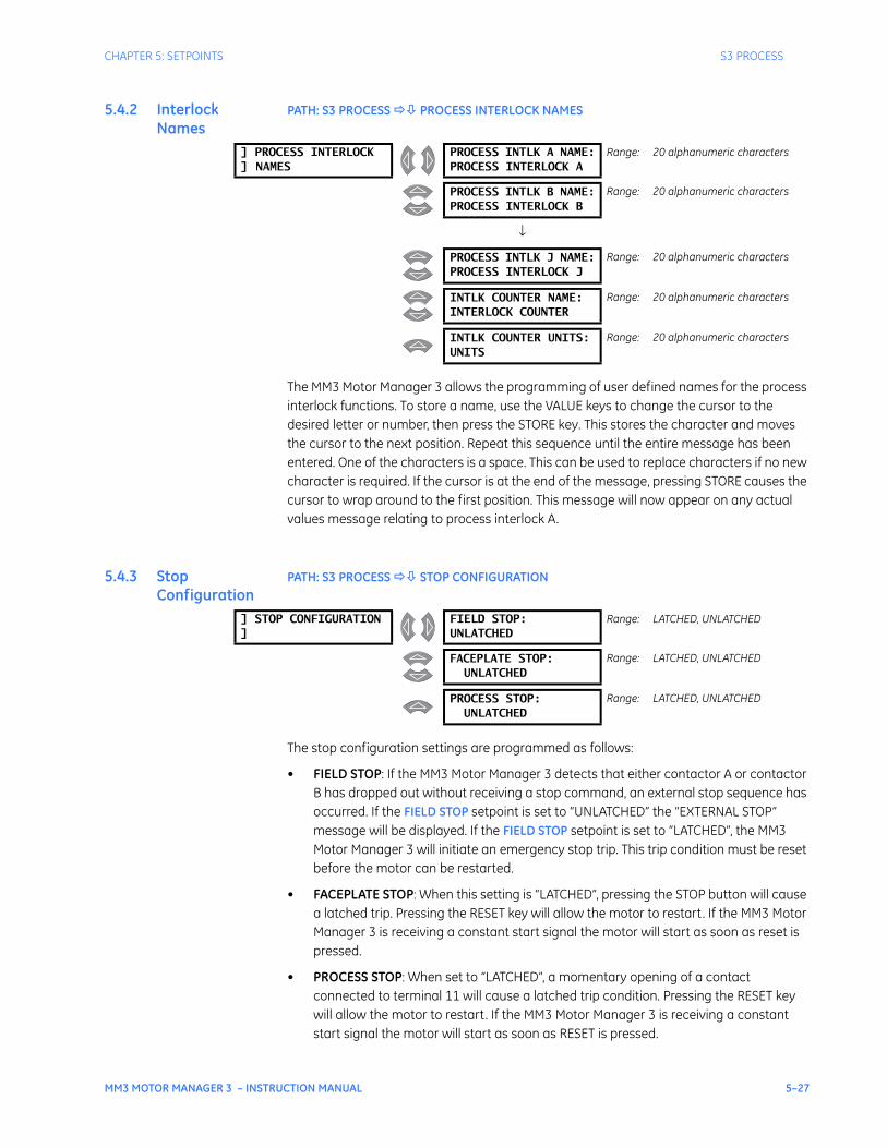
CHAPTER 5: SETPOINTS S3 PROCESS
MM3 MOTOR MANAGER 3 – INSTRUCTION MANUAL 5–27
5.4.2 Interlock Names
PATH: S3 PROCESS PROCESS INTERLOCK NAMES
The MM3 Motor Manager 3 allows the programming of user defined names for the process interlock functions. To store a name, use the VALUE keys to change the cursor to the desired letter or number, then press the STORE key. This stores the character and moves the cursor to the next position. Repeat this sequence until the entire message has been entered. One of the characters is a space. This can be used to replace characters if no new character is required. If the cursor is at the end of the message, pressing STORE causes the cursor to wrap around to the first position. This message will now appear on any actual values message relating to process interlock A.
5.4.3 Stop Configuration
PATH: S3 PROCESS STOP CONFIGURATION
The stop configuration settings are programmed as follows:
• FIELD STOP: If the MM3 Motor Manager 3 detects that either contactor A or contactor B has dropped out without receiving a stop command, an external stop sequence has occurred. If the FIELD STOP setpoint is set to “UNLATCHED” the “EXTERNAL STOP” message will be displayed. If the FIELD STOP setpoint is set to “LATCHED”, the MM3 Motor Manager 3 will initiate an emergency stop trip. This trip condition must be reset before the motor can be restarted.
• FACEPLATE STOP: When this setting is “LATCHED”, pressing the STOP button will cause a latched trip. Pressing the RESET key will allow the motor to restart. If the MM3 Motor Manager 3 is receiving a constant start signal the motor will start as soon as reset is pressed.
• PROCESS STOP: When set to “LATCHED”, a momentary opening of a contact connected to terminal 11 will cause a latched trip condition. Pressing the RESET key will allow the motor to restart. If the MM3 Motor Manager 3 is receiving a constant start signal the motor will start as soon as RESET is pressed.
] PROCESS INTERLOCK] NAMES
PROCESS INTLK A NAME:PROCESS INTERLOCK A
Range: 20 alphanumeric characters
PROCESS INTLK B NAME:PROCESS INTERLOCK B
Range: 20 alphanumeric characters
↓
PROCESS INTLK J NAME:PROCESS INTERLOCK J
Range: 20 alphanumeric characters
INTLK COUNTER NAME:INTERLOCK COUNTER
Range: 20 alphanumeric characters
INTLK COUNTER UNITS:UNITS
Range: 20 alphanumeric characters
] STOP CONFIGURATION]
FIELD STOP:UNLATCHED
Range: LATCHED, UNLATCHED
FACEPLATE STOP:UNLATCHED
Range: LATCHED, UNLATCHED
PROCESS STOP:UNLATCHED
Range: LATCHED, UNLATCHED
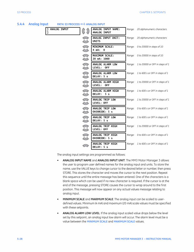
5–28 MM3 MOTOR MANAGER 3 – INSTRUCTION MANUAL
S3 PROCESS CHAPTER 5: SETPOINTS
5.4.4 Analog Input PATH: S3 PROCESS ANALOG INPUT
The analog input settings are programmed as follows:
• ANALOG INPUT NAME and ANALOG INPUT UNIT: The MM3 Motor Manager 3 allows the user to program user defined names for the analog input and units. To store the name, use the VALUE keys to change cursor to the desired letter or number, then press STORE. This stores the character and moves the cursor to the next position. Repeat this sequence until the entire message has been entered. One of the characters is a blank space which can be used if no new character is required. If the cursor is at the end of the message, pressing STORE causes the cursor to wrap around to the first position. This message will now appear on any actual values message relating to analog input.
• MINIMUM SCALE and MAXIMUM SCALE: The analog input can be scaled to user-defined values. Minimum (4 mA) and maximum (20 mA) scale values must be specified with these setpoints.
• ANALOG ALARM LOW LEVEL: If the analog input scaled value drops below the level set by this setpoint, an analog input low alarm will occur. The alarm level must be a value between the MINIMUM SCALE and MAXIMUM SCALE values.
] ANALOG INPUT]
ANALOG INPUT NAME:ANALOG INPUT
Range: 20 alphanumeric characters
ANALOG INPUT UNIT:UNITS
Range: 20 alphanumeric characters
MINIMUM SCALE:4 mA: 0
Range: 0 to 20000 in steps of 10
MAXIMUM SCALE:20 mA: 1000
Range: 0 to 20000 in steps of 10
ANALOG ALARM LOWLEVEL: OFF
Range: 1 to 20000 or OFF in steps of 1
ANALOG ALARM LOWDELAY: 5 s
Range: 1 to 600 s or OFF in steps of 1
ANALOG ALARM HIGHLEVEL: OFF
Range: 1 to 20000 or OFF in steps of 1
ANALOG ALARM HIGHDELAY: 5 s
Range: 1 to 600 s or OFF in steps of 1
ANALOG TRIP LOWLEVEL: OFF
Range: 1 to 20000 or OFF in steps of 1
ANALOG TRIP LOWOVERRIDE: 5 s
Range: 0 to 600 s or OFF in steps of 1
ANALOG TRIP LOWDELAY: 5 s
Range: 1 to 600 s or OFF in steps of 1
ANALOG TRIP HIGHLEVEL: OFF
Range: 1 to 20000 or OFF in steps of 1
ANALOG TRIP HIGHOVERRIDE: 5 s
Range: 0 to 600 s or OFF in steps of 1
ANALOG TRIP HIGHDELAY: 5 s
Range: 1 to 600 s or OFF in steps of 1
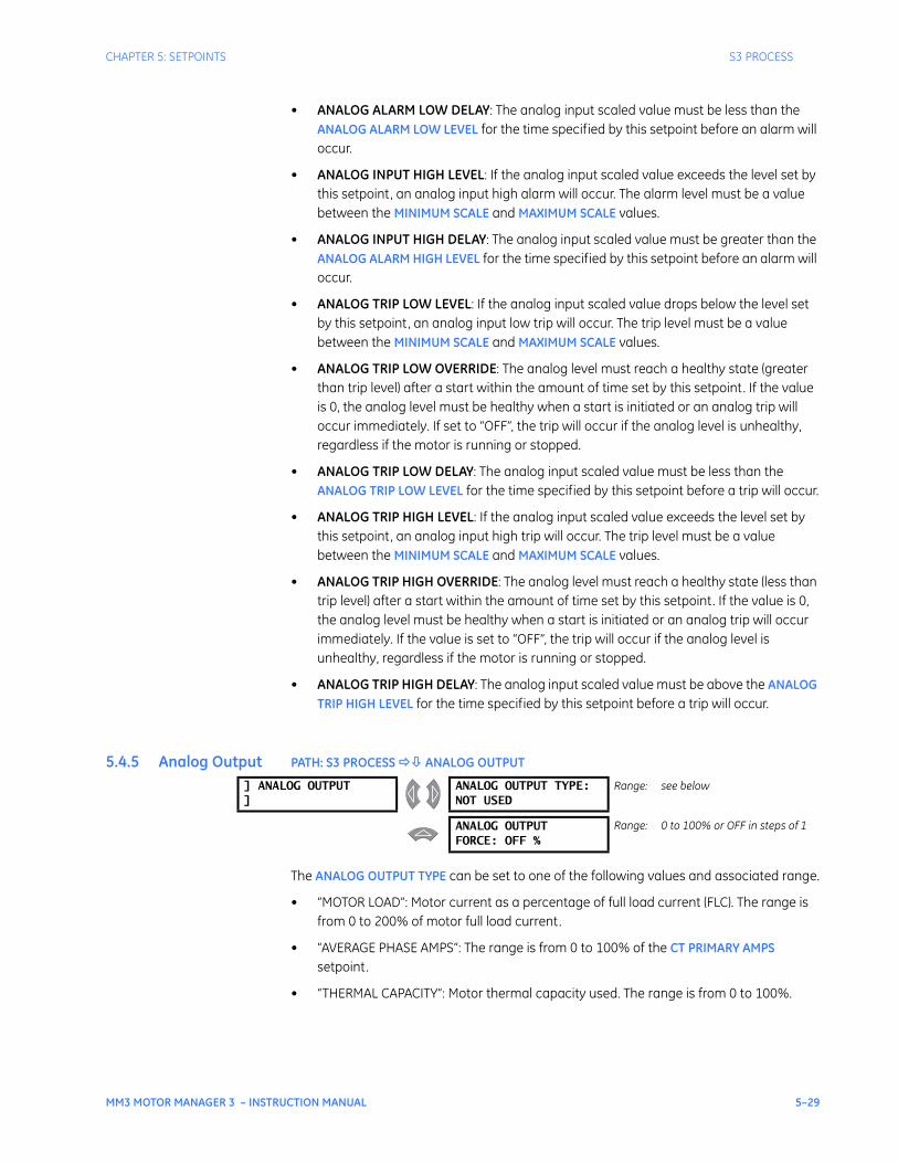
CHAPTER 5: SETPOINTS S3 PROCESS
MM3 MOTOR MANAGER 3 – INSTRUCTION MANUAL 5–29
• ANALOG ALARM LOW DELAY: The analog input scaled value must be less than the ANALOG ALARM LOW LEVEL for the time specified by this setpoint before an alarm will occur.
• ANALOG INPUT HIGH LEVEL: If the analog input scaled value exceeds the level set by this setpoint, an analog input high alarm will occur. The alarm level must be a value between the MINIMUM SCALE and MAXIMUM SCALE values.
• ANALOG INPUT HIGH DELAY: The analog input scaled value must be greater than the ANALOG ALARM HIGH LEVEL for the time specified by this setpoint before an alarm will occur.
• ANALOG TRIP LOW LEVEL: If the analog input scaled value drops below the level set by this setpoint, an analog input low trip will occur. The trip level must be a value between the MINIMUM SCALE and MAXIMUM SCALE values.
• ANALOG TRIP LOW OVERRIDE: The analog level must reach a healthy state (greater than trip level) after a start within the amount of time set by this setpoint. If the value is 0, the analog level must be healthy when a start is initiated or an analog trip will occur immediately. If set to “OFF”, the trip will occur if the analog level is unhealthy, regardless if the motor is running or stopped.
• ANALOG TRIP LOW DELAY: The analog input scaled value must be less than the ANALOG TRIP LOW LEVEL for the time specified by this setpoint before a trip will occur.
• ANALOG TRIP HIGH LEVEL: If the analog input scaled value exceeds the level set by this setpoint, an analog input high trip will occur. The trip level must be a value between the MINIMUM SCALE and MAXIMUM SCALE values.
• ANALOG TRIP HIGH OVERRIDE: The analog level must reach a healthy state (less than trip level) after a start within the amount of time set by this setpoint. If the value is 0, the analog level must be healthy when a start is initiated or an analog trip will occur immediately. If the value is set to “OFF”, the trip will occur if the analog level is unhealthy, regardless if the motor is running or stopped.
• ANALOG TRIP HIGH DELAY: The analog input scaled value must be above the ANALOG TRIP HIGH LEVEL for the time specified by this setpoint before a trip will occur.
5.4.5 Analog Output PATH: S3 PROCESS ANALOG OUTPUT
The ANALOG OUTPUT TYPE can be set to one of the following values and associated range.
• “MOTOR LOAD”: Motor current as a percentage of full load current (FLC). The range is from 0 to 200% of motor full load current.
• “AVERAGE PHASE AMPS”: The range is from 0 to 100% of the CT PRIMARY AMPS setpoint.
• “THERMAL CAPACITY”: Motor thermal capacity used. The range is from 0 to 100%.
] ANALOG OUTPUT]
ANALOG OUTPUT TYPE:NOT USED
Range: see below
ANALOG OUTPUTFORCE: OFF %
Range: 0 to 100% or OFF in steps of 1
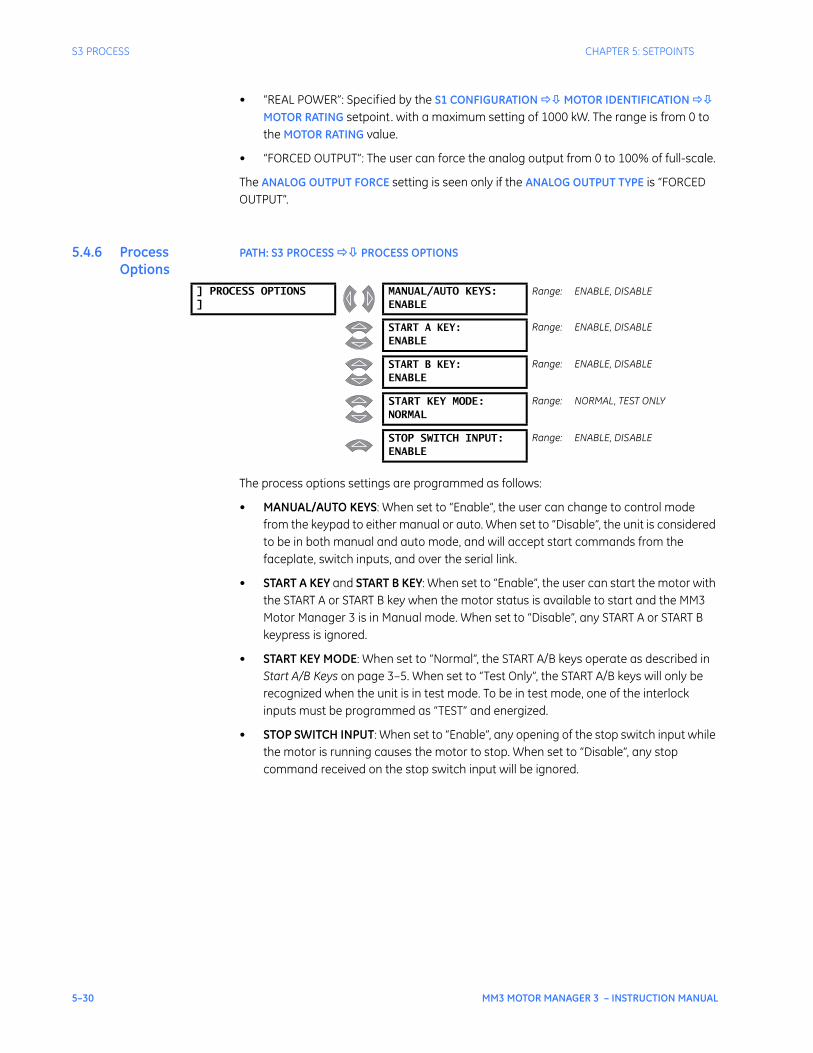
5–30 MM3 MOTOR MANAGER 3 – INSTRUCTION MANUAL
S3 PROCESS CHAPTER 5: SETPOINTS
• “REAL POWER”: Specified by the S1 CONFIGURATION MOTOR IDENTIFICATION MOTOR RATING setpoint. with a maximum setting of 1000 kW. The range is from 0 to the MOTOR RATING value.
• “FORCED OUTPUT”: The user can force the analog output from 0 to 100% of full-scale.
The ANALOG OUTPUT FORCE setting is seen only if the ANALOG OUTPUT TYPE is “FORCED OUTPUT”.
5.4.6 Process Options
PATH: S3 PROCESS PROCESS OPTIONS
The process options settings are programmed as follows:
• MANUAL/AUTO KEYS: When set to “Enable”, the user can change to control mode from the keypad to either manual or auto. When set to “Disable”, the unit is considered to be in both manual and auto mode, and will accept start commands from the faceplate, switch inputs, and over the serial link.
• START A KEY and START B KEY: When set to “Enable”, the user can start the motor with the START A or START B key when the motor status is available to start and the MM3 Motor Manager 3 is in Manual mode. When set to “Disable”, any START A or START B keypress is ignored.
• START KEY MODE: When set to “Normal”, the START A/B keys operate as described in Start A/B Keys on page 3–5. When set to “Test Only”, the START A/B keys will only be recognized when the unit is in test mode. To be in test mode, one of the interlock inputs must be programmed as “TEST” and energized.
• STOP SWITCH INPUT: When set to “Enable”, any opening of the stop switch input while the motor is running causes the motor to stop. When set to “Disable”, any stop command received on the stop switch input will be ignored.
] PROCESS OPTIONS]
MANUAL/AUTO KEYS:ENABLE
Range: ENABLE, DISABLE
START A KEY:ENABLE
Range: ENABLE, DISABLE
START B KEY:ENABLE
Range: ENABLE, DISABLE
START KEY MODE:NORMAL
Range: NORMAL, TEST ONLY
STOP SWITCH INPUT:ENABLE
Range: ENABLE, DISABLE
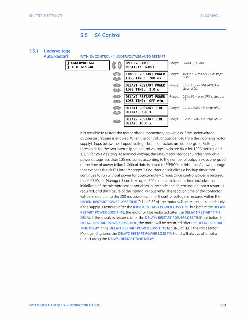
CHAPTER 5: SETPOINTS S4 CONTROL
MM3 MOTOR MANAGER 3 – INSTRUCTION MANUAL 5–31
5.5 S4 Control
5.5.1 Undervoltage Auto Restart PATH: S4 CONTROL UNDERVOLTAGE AUTO RESTART
It is possible to restart the motor after a momentary power loss if the undervoltage autorestart feature is enabled. When the control voltage (derived from the incoming motor supply) drops below the dropout voltage, both contactors are de-energized. Voltage thresholds for the two internally set control voltage levels are 80 V for 120 V setting and 150 V for 240 V setting. At nominal voltage, the MM3 Motor Manager 3 rides through a power outage less than 135 ms (varies according to the number of output relays energized at the time of power failure). Critical data is saved to E2PROM at this time. A power outage that exceeds the MM3 Motor Manager 3 ride-through initializes a backup timer that continues to run without power for approximately 1 hour. Once control power is restored, the MM3 Motor Manager 3 can take up to 300 ms to initialize; this time includes the initializing of the microprocessor, variables in the code, the determination that a restart is required, and the closure of the internal output relay. The reaction time of the contactor will be in addition to the 300 ms power-up time. If control voltage is restored within the IMMED. RESTART POWER LOSS TIME (0.1 to 0.52 s), the motor will be restarted immediately. If the supply is restored after the IMMED. RESTART POWER LOSS TIME but before the DELAY1 RESTART POWER LOSS TIME, the motor will be restarted after the DELAY 1 RESTART TIME DELAY. If the supply is restored after the DELAY1 RESTART POWER LOSS TIME but before the DELAY2 RESTART POWER LOSS TIME, the motor will be restarted after the DELAY2 RESTART TIME DELAY. If the DELAY1 RESTART POWER LOSS TIME to “UNLIMITED”, the MM3 Motor Manager 3 ignores the DELAY2 RESTART POWER LOSS TIME and will always attempt a restart using the DELAY1 RESTART TIME DELAY.
] UNDERVOLTAGE] AUTO RESTART
UNDERVOLTAGERESTART: ENABLE
Range: ENABLE, DISABLE
IMMED. RESTART POWERLOSS TIME: 200 ms
Range: 100 to 520 ms or OFF in steps of 20
DELAY1 RESTART POWERLOSS TIME: 2.0 s
Range: 0.1 to 10 s or UNLIMITED in steps of 0.1
DELAY2 RESTART POWERLOSS TIME: OFF min.
Range: 0.5 to 60 min. or OFF in steps of 0.5
DELAY1 RESTART TIMEDELAY: 2.0 s
Range: 0.2 to 1200.0 s in steps of 0.2
DELAY2 RESTART TIMEDELAY: 10.0 s
Range: 0.2 to 1200.0 s in steps of 0.2
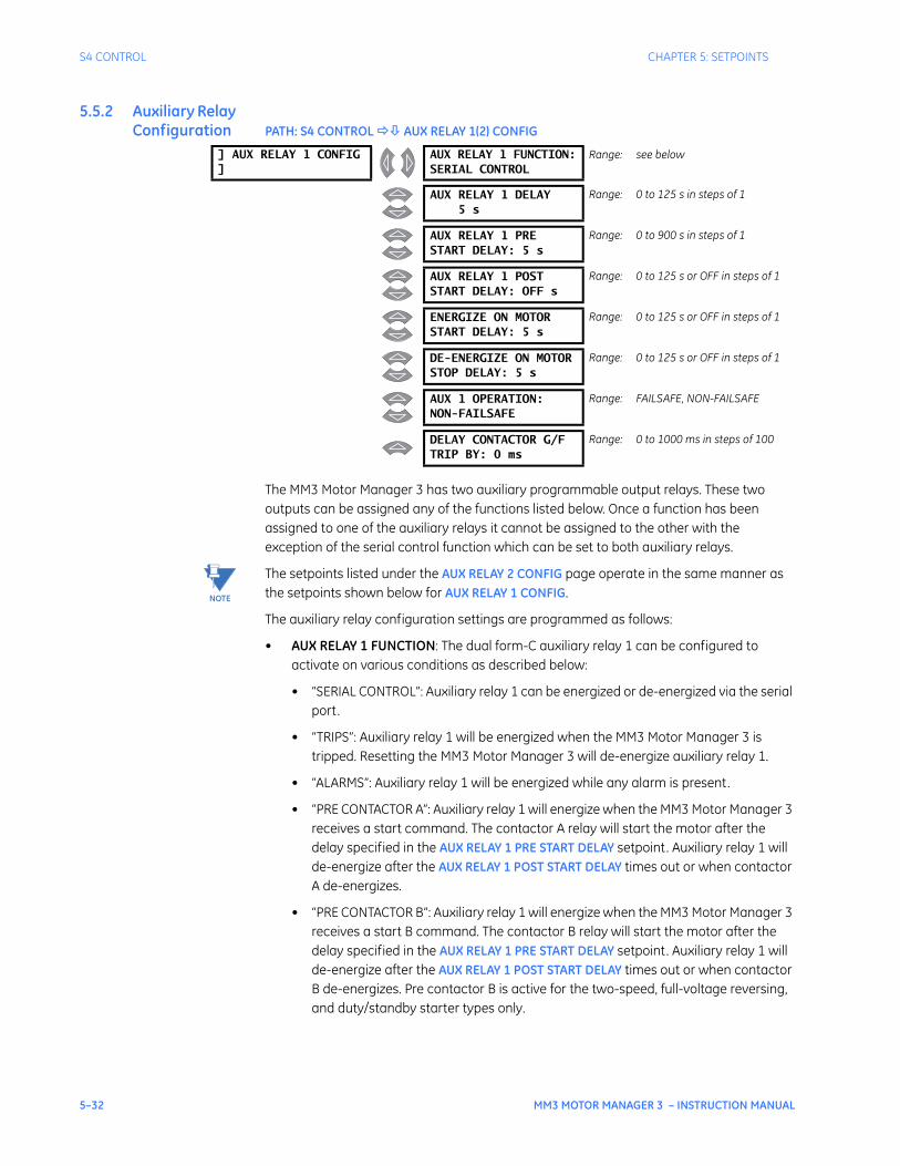
5–32 MM3 MOTOR MANAGER 3 – INSTRUCTION MANUAL
S4 CONTROL CHAPTER 5: SETPOINTS
5.5.2 Auxiliary Relay Configuration PATH: S4 CONTROL AUX RELAY 1(2) CONFIG
The MM3 Motor Manager 3 has two auxiliary programmable output relays. These two outputs can be assigned any of the functions listed below. Once a function has been assigned to one of the auxiliary relays it cannot be assigned to the other with the exception of the serial control function which can be set to both auxiliary relays.
The setpoints listed under the AUX RELAY 2 CONFIG page operate in the same manner as the setpoints shown below for AUX RELAY 1 CONFIG.
The auxiliary relay configuration settings are programmed as follows:
• AUX RELAY 1 FUNCTION: The dual form-C auxiliary relay 1 can be configured to activate on various conditions as described below:
• “SERIAL CONTROL”: Auxiliary relay 1 can be energized or de-energized via the serial port.
• “TRIPS”: Auxiliary relay 1 will be energized when the MM3 Motor Manager 3 is tripped. Resetting the MM3 Motor Manager 3 will de-energize auxiliary relay 1.
• “ALARMS”: Auxiliary relay 1 will be energized while any alarm is present.
• “PRE CONTACTOR A”: Auxiliary relay 1 will energize when the MM3 Motor Manager 3 receives a start command. The contactor A relay will start the motor after the delay specified in the AUX RELAY 1 PRE START DELAY setpoint. Auxiliary relay 1 will de-energize after the AUX RELAY 1 POST START DELAY times out or when contactor A de-energizes.
• “PRE CONTACTOR B”: Auxiliary relay 1 will energize when the MM3 Motor Manager 3 receives a start B command. The contactor B relay will start the motor after the delay specified in the AUX RELAY 1 PRE START DELAY setpoint. Auxiliary relay 1 will de-energize after the AUX RELAY 1 POST START DELAY times out or when contactor B de-energizes. Pre contactor B is active for the two-speed, full-voltage reversing, and duty/standby starter types only.
] AUX RELAY 1 CONFIG]
AUX RELAY 1 FUNCTION:SERIAL CONTROL
Range: see below
AUX RELAY 1 DELAY5 s
Range: 0 to 125 s in steps of 1
AUX RELAY 1 PRESTART DELAY: 5 s
Range: 0 to 900 s in steps of 1
AUX RELAY 1 POSTSTART DELAY: OFF s
Range: 0 to 125 s or OFF in steps of 1
ENERGIZE ON MOTORSTART DELAY: 5 s
Range: 0 to 125 s or OFF in steps of 1
DE-ENERGIZE ON MOTORSTOP DELAY: 5 s
Range: 0 to 125 s or OFF in steps of 1
AUX 1 OPERATION:NON-FAILSAFE
Range: FAILSAFE, NON-FAILSAFE
DELAY CONTACTOR G/FTRIP BY: 0 ms
Range: 0 to 1000 ms in steps of 100
NOTE
CHAPTER 5: SETPOINTS S4 CONTROL
MM3 MOTOR MANAGER 3 – INSTRUCTION MANUAL 5–33
• “POST CONTACTOR A” and “POST CONTACTOR B”: Auxiliary relay 1 will energize after the contactor A/B relay in the time specified by the AUX RELAY 1 DELAY setpoint. Auxiliary relay 1 will de-energize when contactor A/B de-energizes.
• “MOTOR AVAILABLE MANUAL”: When the motor status message indicates that the motor can be started manually, auxiliary relay 1 will be energized. Any other motor status indication will cause auxiliary relay 1 to be de-energized.
• “LOAD INCREASE”: Auxiliary relay 1 will energize while a load increase alarm is present.
• “UNDERCURRENT TRIP”: Auxiliary relay 1 will energize while an undercurrent trip is present.
• “UNDERPOWER TRIP”: Auxiliary relay 1 will energize while an underpower trip is present.
• “KEYPAD RESET”: Auxiliary relay 1 will energize while the RESET key is pressed.
• “INTERLOCK 1” through “INTERLOCK 10”: Auxiliary relay 1 will energize while the interlock 1 through 10 switch inputs are closed, respectively.
• “AUTO MODE”: Auxiliary relay 1 will energize when the Auto LED is on.
• “MOTOR RUNNING”: Auxiliary relay 1 will energize while the motor is running in conjunction with the motor start delay and motor stop delay.
• “GROUND FAULT TRIP”: Auxiliary relay 1 will energize when a ground fault trip occurs.
The MM3 Motor Manager 3 energizes the auxiliary relay and de-energizes contactor A at the same time the ground fault trip occurs. See Motor Protection: Ground Fault on page 5–16 for details. Use the DELAY CONTACTOR GROUND FAULT TRIP BY setting for coordination.
• “WYE DELTA CLS TRANS”: This function must be configured when using the wye delta closed transition starter type. See Wye-delta Closed Transition Starter on page 2–32 for details.
• “AUTOTRANSFORMER 2S”: This function must be configured when using the autotransformer open/closed transition starter type. See Autotransformer Open Transition Starter on page 2–21 and Autotransformer Closed Transition Starter on page 2–25 for details.
• “NOT USED”: This function may be stored if the auxiliary relay is not used. The factory default is serial control.
• “SEGREGATED G/F ALARM”: This function will energize the auxiliary relay when a ground fault alarm occurs. If the other auxiliary relay is configured for alarms, it will not operate until another alarm occurs that is not a ground fault alarm.
• “THERMAL CAPACITY ALARM”: Auxiliary relay 1 will energize when a thermal capacity alarm is present.
• “MOTOR AVAILABLE AUTO”: This function will activate the auxiliary relay when the motor is available to start in auto mode.
• “MOTOR AVAILABLE”: This function will activate the auxiliary relay when the motor is available to start regardless of which mode the MM3 Motor Manager 3 is presently in (auto or manual). The auxiliary relay will remain active when the motor is running to indicate normal operation (that is, no stop inputs or trips).
CAUTION

5–34 MM3 MOTOR MANAGER 3 – INSTRUCTION MANUAL
S4 CONTROL CHAPTER 5: SETPOINTS
• “OVERLOAD”: This function will activate the auxiliary relay when the motor is tripped on overload.
• “SOFT STARTER BYPASS”: This function can be configured when using soft starter type. See Soft Starter on page 2–36 for details.
• AUX RELAY 1 DELAY: Provides a delayed energization of auxiliary relay 1 when “POST CONTACTOR A” or “POST CONTACTOR B” is selected as the AUX RELAY 1 FUNCTION.
• AUX RELAY 1 PRE START DELAY: Determines how long auxiliary relay 1 will energize before energizing contactor A. When set to “0 s”, both auxiliary relay 1 and contactor A will energize at the same time.
• AUX RELAY 1 POST START DELAY: Determines how long auxiliary relay 1 remains energized after contactor A closes. When set to “0 s”, auxiliary relay 1 de-energizes as soon as contactor A closes. When set to “OFF”, auxiliary relay 1 remains energized until contactor A opens.
• ENERGIZE ON MOTOR START DELAY: Provides a delayed energization of auxiliary relay 1 when “MOTOR RUNNING” is selected as the AUX RELAY 1 FUNCTION. Auxiliary relay 1 energizes after this time delay on the occurrence of a motor start.
• DE-ENERGIZE ON MOTOR STOP DELAY: Provides a delayed de-energization of auxiliary relay 1 when “MOTOR RUNNING” is selected as the AUX RELAY 1 FUNCTION. Auxiliary relay 1 will de-energize after this time delay on the occurrence of a motor stop.
• AUX 1 OPERATION: Choose between non-failsafe or failsafe operation of auxiliary relay 1. In “NON-FAILSAFE” mode, the relay will be de-energized in its inactive state and energized in its active state. In “FAILSAFE” mode, the relay will be energized in its inactive state and de-energized in its active state.
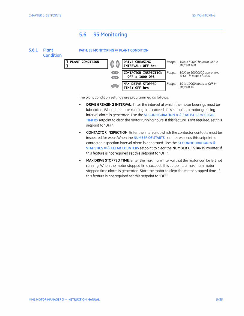
CHAPTER 5: SETPOINTS S5 MONITORING
MM3 MOTOR MANAGER 3 – INSTRUCTION MANUAL 5–35
5.6 S5 Monitoring
5.6.1 Plant Condition
PATH: S5 MONITORING PLANT CONDITION
The plant condition settings are programmed as follows:
• DRIVE GREASING INTERVAL: Enter the interval at which the motor bearings must be lubricated. When the motor running time exceeds this setpoint, a motor greasing interval alarm is generated. Use the S1 CONFIGURATION STATISTICS CLEAR TIMERS setpoint to clear the motor running hours. If this feature is not required. set this setpoint to “OFF”.
• CONTACTOR INSPECTION: Enter the interval at which the contactor contacts must be inspected for wear. When the NUMBER OF STARTS counter exceeds this setpoint, a contactor inspection interval alarm is generated. Use the S1 CONFIGURATION STATISTICS CLEAR COUNTERS setpoint to clear the NUMBER OF STARTS counter. If this feature is not required set this setpoint to “OFF”.
• MAX DRIVE STOPPED TIME: Enter the maximum interval that the motor can be left not running. When the motor stopped time exceeds this setpoint, a maximum motor stopped time alarm is generated. Start the motor to clear the motor stopped time. If this feature is not required set this setpoint to “OFF”.
] PLANT CONDITION]
DRIVE GREASINGINTERVAL: OFF hrs
Range: 100 to 50000 hours or OFF in steps of 100
CONTACTOR INSPECTIONOFF x 1000 OPS
Range: 1000 to 10000000 operations or OFF in steps of 1000
MAX DRIVE STOPPEDTIME: OFF hrs
Range: 10 to 10000 hours or OFF in steps of 10
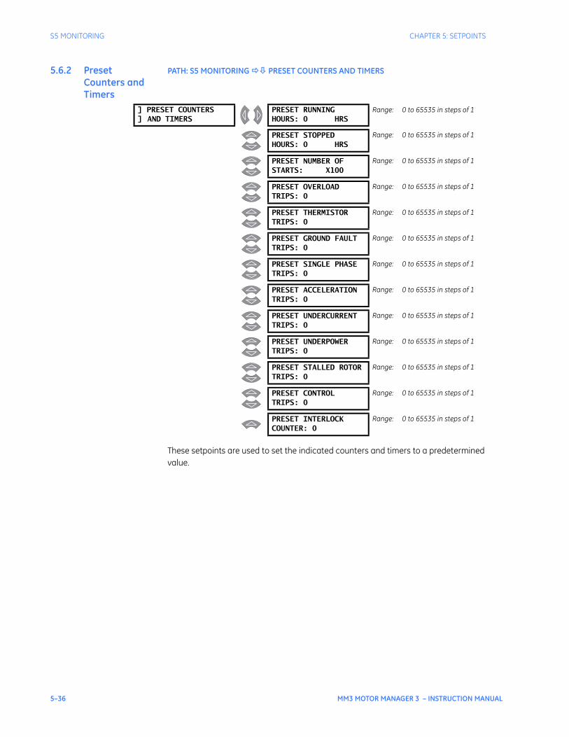
5–36 MM3 MOTOR MANAGER 3 – INSTRUCTION MANUAL
S5 MONITORING CHAPTER 5: SETPOINTS
5.6.2 Preset Counters and Timers
PATH: S5 MONITORING PRESET COUNTERS AND TIMERS
These setpoints are used to set the indicated counters and timers to a predetermined value.
] PRESET COUNTERS] AND TIMERS
PRESET RUNNINGHOURS: 0 HRS
Range: 0 to 65535 in steps of 1
PRESET STOPPEDHOURS: 0 HRS
Range: 0 to 65535 in steps of 1
PRESET NUMBER OFSTARTS: X100
Range: 0 to 65535 in steps of 1
PRESET OVERLOADTRIPS: 0
Range: 0 to 65535 in steps of 1
PRESET THERMISTORTRIPS: 0
Range: 0 to 65535 in steps of 1
PRESET GROUND FAULTTRIPS: 0
Range: 0 to 65535 in steps of 1
PRESET SINGLE PHASETRIPS: 0
Range: 0 to 65535 in steps of 1
PRESET ACCELERATIONTRIPS: 0
Range: 0 to 65535 in steps of 1
PRESET UNDERCURRENTTRIPS: 0
Range: 0 to 65535 in steps of 1
PRESET UNDERPOWERTRIPS: 0
Range: 0 to 65535 in steps of 1
PRESET STALLED ROTORTRIPS: 0
Range: 0 to 65535 in steps of 1
PRESET CONTROLTRIPS: 0
Range: 0 to 65535 in steps of 1
PRESET INTERLOCKCOUNTER: 0
Range: 0 to 65535 in steps of 1
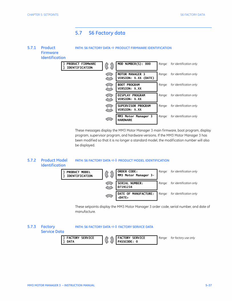
CHAPTER 5: SETPOINTS S6 FACTORY DATA
MM3 MOTOR MANAGER 3 – INSTRUCTION MANUAL 5–37
5.7 S6 Factory data
5.7.1 Product Firmware Identification
PATH: S6 FACTORY DATA PRODUCT FIRMWARE IDENTIFICATION
These messages display the MM3 Motor Manager 3 main firmware, boot program, display program, supervisor program, and hardware versions. If the MM3 Motor Manager 3 has been modified so that it is no longer a standard model, the modification number will also be displayed.
5.7.2 Product Model Identification
PATH: S6 FACTORY DATA PRODUCT MODEL IDENTIFICATION
These setpoints display the MM3 Motor Manager 3 order code, serial number, and date of manufacture.
5.7.3 Factory Service Data
PATH: S6 FACTORY DATA FACTORY SERVICE DATA
] PRODUCT FIRMWARE] IDENTIFICATION
MOD NUMBER(S): 000 Range: for identification only
MOTOR MANAGER 3VERSION: X.XX (DATE)
Range: for identification only
BOOT PROGRAMVERSION: X.XX
Range: for identification only
DISPLAY PROGRAMVERSION: X.XX
Range: for identification only
SUPERVISOR PROGRAMVERSION: X.XX
Range: for identification only
MM3 Motor Manager 3 HARDWARE
Range: for identification only
] PRODUCT MODEL] IDENTIFICATION
ORDER CODE:MM3 Motor Manager 3-
Range: for identification only
SERIAL NUMBER:D7191234
Range: for identification only
DATE OF MANUFACTURE:<DATE>
Range: for identification only
] FACTORY SERVICE] DATA
FACTORY SERVICEPASSCODE: 0
Range: for factory use only
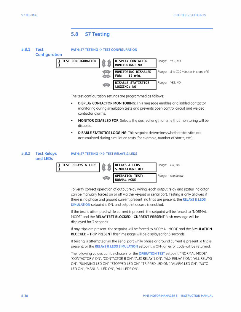
5–38 MM3 MOTOR MANAGER 3 – INSTRUCTION MANUAL
S7 TESTING CHAPTER 5: SETPOINTS
5.8 S7 Testing
5.8.1 Test Configuration
PATH: S7 TESTING TEST CONFIGURATION
The test configuration settings are programmed as follows:
• DISPLAY CONTACTOR MONITORING: This message enables or disabled contactor monitoring during simulation tests and prevents open control circuit and welded contactor alarms.
• MONITOR DISABLED FOR: Selects the desired length of time that monitoring will be disabled.
• DISABLE STATISTICS LOGGING: This setpoint determines whether statistics are accumulated during simulation tests (for example, number of starts, etc.).
5.8.2 Test Relays and LEDs
PATH: S7 TESTING TEST RELAYS & LEDS
To verify correct operation of output relay wiring, each output relay and status indicator can be manually forced on or off via the keypad or serial port. Testing is only allowed if there is no phase and ground current present, no trips are present, the RELAYS & LEDS SIMULATION setpoint is ON, and setpoint access is enabled.
If the test is attempted while current is present, the setpoint will be forced to “NORMAL MODE” and the RELAY TEST BLOCKED - CURRENT PRESENT flash message will be displayed for 3 seconds.
If any trips are present, the setpoint will be forced to NORMAL MODE and the SIMULATION BLOCKED - TRIP PRESENT flash message will be displayed for 3 seconds.
If testing is attempted via the serial port while phase or ground current is present, a trip is present, or the RELAYS & LEDS SIMULATION setpoint is OFF, an error code will be returned.
The following values can be chosen for the OPERATION TEST setpoint: “NORMAL MODE”, “CONTACTOR A ON”, “CONTACTOR B ON”, “AUX RELAY 1 ON”, “AUX RELAY 2 ON”, “ALL RELAYS ON”, “RUNNING LED ON”, “STOPPED LED ON”, “TRIPPED LED ON”, “ALARM LED ON”, “AUTO LED ON”, “MANUAL LED ON”, “ALL LEDS ON”.
] TEST CONFIGURATION]
DISPLAY CONTACTORMONITORING: NO
Range: YES, NO
MONITORING DISABLEDFOR: 15 min.
Range: 5 to 300 minutes in steps of 5
DISABLE STATISTICSLOGGING: NO
Range: YES, NO
] TEST RELAYS & LEDS]
RELAYS & LEDSSIMULATION: OFF
Range: ON, OFF
OPERATION TEST:NORMAL MODE
Range: see below
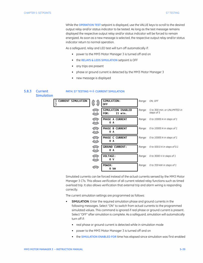
CHAPTER 5: SETPOINTS S7 TESTING
MM3 MOTOR MANAGER 3 – INSTRUCTION MANUAL 5–39
While the OPERATION TEST setpoint is displayed, use the VALUE keys to scroll to the desired output relay and/or status indicator to be tested. As long as the test message remains displayed the respective output relay and/or status indicator will be forced to remain energized. As soon as a new message is selected, the respective output relay and/or status indicator return to normal operation.
As a safeguard, relay and LED test will turn off automatically if:
• power to the MM3 Motor Manager 3 is turned off and on
• the RELAYS & LEDS SIMULATION setpoint is OFF
• any trips are present
• phase or ground current is detected by the MM3 Motor Manager 3
• new message is displayed
5.8.3 Current Simulation
PATH: S7 TESTING CURRENT SIMULATION
Simulated currents can be forced instead of the actual currents sensed by the MM3 Motor Manager 3 CTs. This allows verification of all current related relay functions such as timed overload trip. It also allows verification that external trip and alarm wiring is responding correctly.
The current simulation settings are programmed as follows:
• SIMULATION: Enter the required simulation phase and ground currents in the following messages. Select “ON” to switch from actual currents to the programmed simulated values. This command is ignored if real phase or ground current is present. Select “OFF” after simulation is complete. As a safeguard, simulation will automatically turn off if:
• real phase or ground current is detected while in simulation mode
• power to the MM3 Motor Manager 3 is turned off and on
• the SIMULATION ENABLED FOR time has elapsed since simulation was first enabled
] CURRENT SIMULATION]
SIMULATION:OFF
Range: ON, OFF
SIMULATION ENABLEDFOR: 15 min.
Range: 5 to 300 min. or UNLIMITED in steps of 5
PHASE A CURRENT0 A
Range: 0 to 10000 A in steps of 1
PHASE B CURRENT0 A
Range: 0 to 10000 A in steps of 1
PHASE C CURRENT0 A
Range: 0 to 10000 A in steps of 1
GROUND CURRENT:0 A
Range: 0 to 500.0 A in steps of 0.1
VOLTAGE:0 V
Range: 0 to 3000 V in steps of 1
POWER:0 kW
Range: 0 to 359 kW in steps of 1
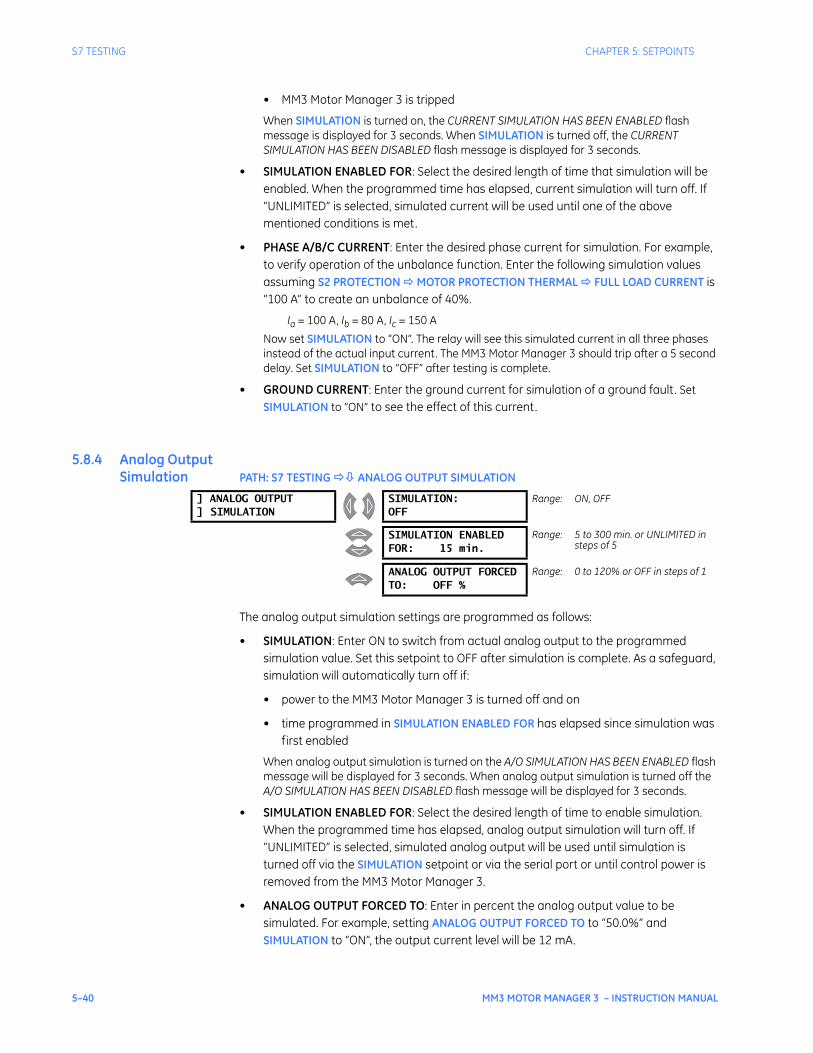
5–40 MM3 MOTOR MANAGER 3 – INSTRUCTION MANUAL
S7 TESTING CHAPTER 5: SETPOINTS
• MM3 Motor Manager 3 is tripped
When SIMULATION is turned on, the CURRENT SIMULATION HAS BEEN ENABLED flash message is displayed for 3 seconds. When SIMULATION is turned off, the CURRENT SIMULATION HAS BEEN DISABLED flash message is displayed for 3 seconds.
• SIMULATION ENABLED FOR: Select the desired length of time that simulation will be enabled. When the programmed time has elapsed, current simulation will turn off. If “UNLIMITED” is selected, simulated current will be used until one of the above mentioned conditions is met.
• PHASE A/B/C CURRENT: Enter the desired phase current for simulation. For example, to verify operation of the unbalance function. Enter the following simulation values assuming S2 PROTECTION MOTOR PROTECTION THERMAL FULL LOAD CURRENT is “100 A” to create an unbalance of 40%.
Ia = 100 A, Ib = 80 A, Ic = 150 ANow set SIMULATION to “ON”. The relay will see this simulated current in all three phases instead of the actual input current. The MM3 Motor Manager 3 should trip after a 5 second delay. Set SIMULATION to “OFF” after testing is complete.
• GROUND CURRENT: Enter the ground current for simulation of a ground fault. Set SIMULATION to “ON” to see the effect of this current.
5.8.4 Analog Output Simulation PATH: S7 TESTING ANALOG OUTPUT SIMULATION
The analog output simulation settings are programmed as follows:
• SIMULATION: Enter ON to switch from actual analog output to the programmed simulation value. Set this setpoint to OFF after simulation is complete. As a safeguard, simulation will automatically turn off if:
• power to the MM3 Motor Manager 3 is turned off and on
• time programmed in SIMULATION ENABLED FOR has elapsed since simulation was first enabled
When analog output simulation is turned on the A/O SIMULATION HAS BEEN ENABLED flash message will be displayed for 3 seconds. When analog output simulation is turned off the A/O SIMULATION HAS BEEN DISABLED flash message will be displayed for 3 seconds.
• SIMULATION ENABLED FOR: Select the desired length of time to enable simulation. When the programmed time has elapsed, analog output simulation will turn off. If “UNLIMITED” is selected, simulated analog output will be used until simulation is turned off via the SIMULATION setpoint or via the serial port or until control power is removed from the MM3 Motor Manager 3.
• ANALOG OUTPUT FORCED TO: Enter in percent the analog output value to be simulated. For example, setting ANALOG OUTPUT FORCED TO to “50.0%” and SIMULATION to “ON”, the output current level will be 12 mA.
] ANALOG OUTPUT] SIMULATION
SIMULATION:OFF
Range: ON, OFF
SIMULATION ENABLEDFOR: 15 min.
Range: 5 to 300 min. or UNLIMITED in steps of 5
ANALOG OUTPUT FORCEDTO: OFF %
Range: 0 to 120% or OFF in steps of 1
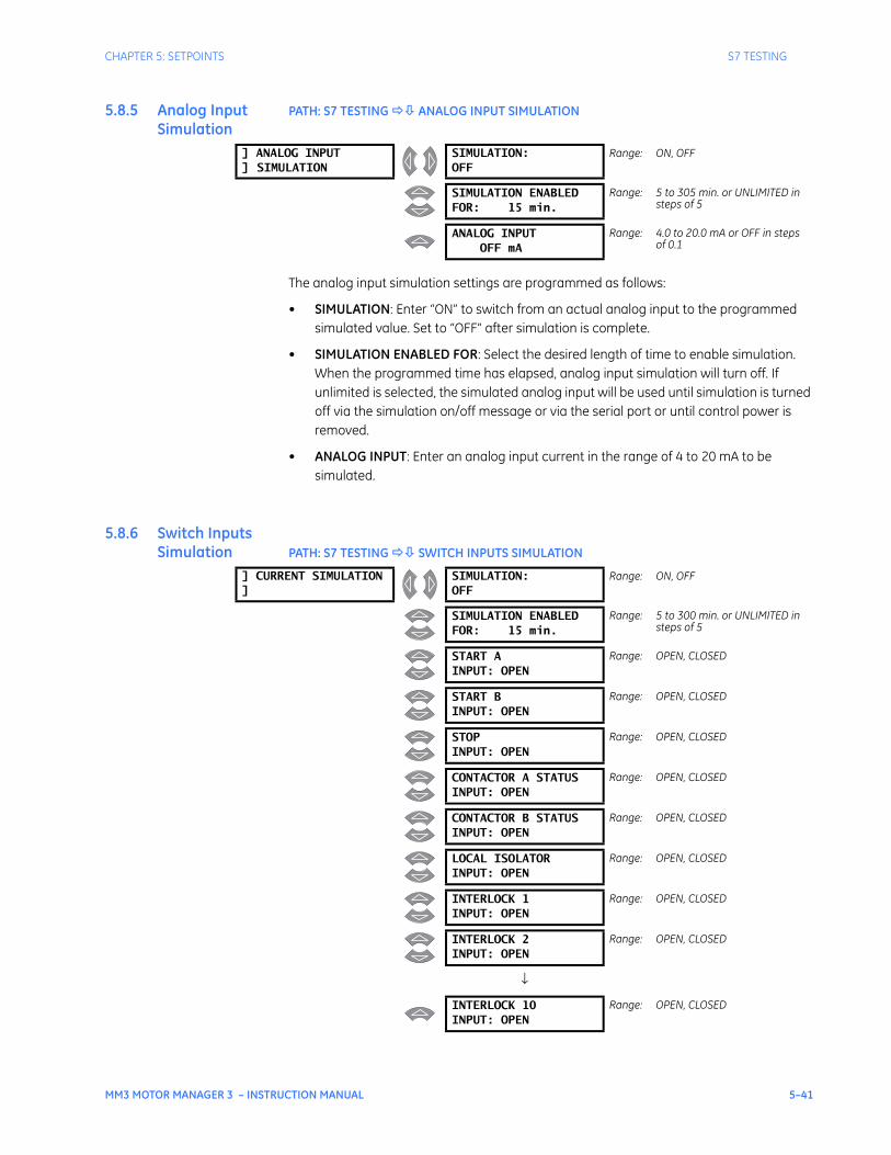
CHAPTER 5: SETPOINTS S7 TESTING
MM3 MOTOR MANAGER 3 – INSTRUCTION MANUAL 5–41
5.8.5 Analog Input Simulation
PATH: S7 TESTING ANALOG INPUT SIMULATION
The analog input simulation settings are programmed as follows:
• SIMULATION: Enter “ON” to switch from an actual analog input to the programmed simulated value. Set to “OFF” after simulation is complete.
• SIMULATION ENABLED FOR: Select the desired length of time to enable simulation. When the programmed time has elapsed, analog input simulation will turn off. If unlimited is selected, the simulated analog input will be used until simulation is turned off via the simulation on/off message or via the serial port or until control power is removed.
• ANALOG INPUT: Enter an analog input current in the range of 4 to 20 mA to be simulated.
5.8.6 Switch Inputs Simulation PATH: S7 TESTING SWITCH INPUTS SIMULATION
] ANALOG INPUT] SIMULATION
SIMULATION:OFF
Range: ON, OFF
SIMULATION ENABLEDFOR: 15 min.
Range: 5 to 305 min. or UNLIMITED in steps of 5
ANALOG INPUTOFF mA
Range: 4.0 to 20.0 mA or OFF in steps of 0.1
] CURRENT SIMULATION]
SIMULATION:OFF
Range: ON, OFF
SIMULATION ENABLEDFOR: 15 min.
Range: 5 to 300 min. or UNLIMITED in steps of 5
START AINPUT: OPEN
Range: OPEN, CLOSED
START BINPUT: OPEN
Range: OPEN, CLOSED
STOPINPUT: OPEN
Range: OPEN, CLOSED
CONTACTOR A STATUSINPUT: OPEN
Range: OPEN, CLOSED
CONTACTOR B STATUSINPUT: OPEN
Range: OPEN, CLOSED
LOCAL ISOLATORINPUT: OPEN
Range: OPEN, CLOSED
INTERLOCK 1INPUT: OPEN
Range: OPEN, CLOSED
INTERLOCK 2INPUT: OPEN
Range: OPEN, CLOSED
↓
INTERLOCK 10INPUT: OPEN
Range: OPEN, CLOSED
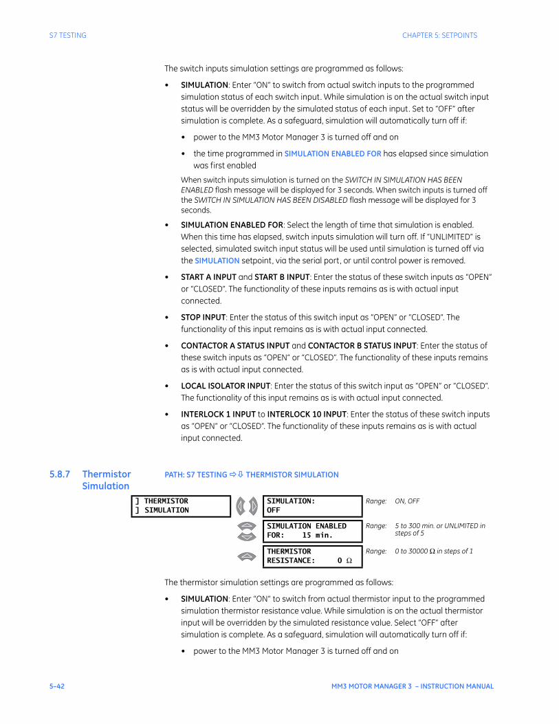
5–42 MM3 MOTOR MANAGER 3 – INSTRUCTION MANUAL
S7 TESTING CHAPTER 5: SETPOINTS
The switch inputs simulation settings are programmed as follows:
• SIMULATION: Enter “ON” to switch from actual switch inputs to the programmed simulation status of each switch input. While simulation is on the actual switch input status will be overridden by the simulated status of each input. Set to “OFF” after simulation is complete. As a safeguard, simulation will automatically turn off if:
• power to the MM3 Motor Manager 3 is turned off and on
• the time programmed in SIMULATION ENABLED FOR has elapsed since simulation was first enabled
When switch inputs simulation is turned on the SWITCH IN SIMULATION HAS BEEN ENABLED flash message will be displayed for 3 seconds. When switch inputs is turned off the SWITCH IN SIMULATION HAS BEEN DISABLED flash message will be displayed for 3 seconds.
• SIMULATION ENABLED FOR: Select the length of time that simulation is enabled. When this time has elapsed, switch inputs simulation will turn off. If “UNLIMITED” is selected, simulated switch input status will be used until simulation is turned off via the SIMULATION setpoint, via the serial port, or until control power is removed.
• START A INPUT and START B INPUT: Enter the status of these switch inputs as “OPEN” or “CLOSED”. The functionality of these inputs remains as is with actual input connected.
• STOP INPUT: Enter the status of this switch input as “OPEN” or “CLOSED”. The functionality of this input remains as is with actual input connected.
• CONTACTOR A STATUS INPUT and CONTACTOR B STATUS INPUT: Enter the status of these switch inputs as “OPEN” or “CLOSED”. The functionality of these inputs remains as is with actual input connected.
• LOCAL ISOLATOR INPUT: Enter the status of this switch input as “OPEN” or “CLOSED”. The functionality of this input remains as is with actual input connected.
• INTERLOCK 1 INPUT to INTERLOCK 10 INPUT: Enter the status of these switch inputs as “OPEN” or “CLOSED”. The functionality of these inputs remains as is with actual input connected.
5.8.7 Thermistor Simulation
PATH: S7 TESTING THERMISTOR SIMULATION
The thermistor simulation settings are programmed as follows:
• SIMULATION: Enter “ON” to switch from actual thermistor input to the programmed simulation thermistor resistance value. While simulation is on the actual thermistor input will be overridden by the simulated resistance value. Select “OFF” after simulation is complete. As a safeguard, simulation will automatically turn off if:
• power to the MM3 Motor Manager 3 is turned off and on
] THERMISTOR] SIMULATION
SIMULATION:OFF
Range: ON, OFF
SIMULATION ENABLEDFOR: 15 min.
Range: 5 to 300 min. or UNLIMITED in steps of 5
THERMISTORRESISTANCE: 0 Ω
Range: 0 to 30000 Ω in steps of 1

CHAPTER 5: SETPOINTS S7 TESTING
MM3 MOTOR MANAGER 3 – INSTRUCTION MANUAL 5–43
• time programmed in SIMULATION ENABLED FOR has elapsed since simulation was first enabled
When thermistor simulation is turned on the THERMISTR SIMULATION HAS BEEN ENABLED flash message will be displayed for 3 seconds. When thermistor simulation is turned off the THERMISTOR SIMULATION HAS BEEN DISABLED flash message will be displayed for 3 seconds.
• SIMULATION ENABLED FOR: Select the desired length of time that simulation will be enabled. When the programmed time has elapsed, thermistor simulation will turn off. If “UNLIMITED” is selected, simulated thermistor input will be used until simulation is turned off via the SIMULATION setpoint or via the serial port or until control power is removed from the MM3 Motor Manager 3.
• THERMISTOR RESISTANCE: Enter the value of the thermistor resistance to be simulated. The functionality of the thermistor remains as is with an actual input connected to the MM3 Motor Manager 3.

5–44 MM3 MOTOR MANAGER 3 – INSTRUCTION MANUAL
S7 TESTING CHAPTER 5: SETPOINTS
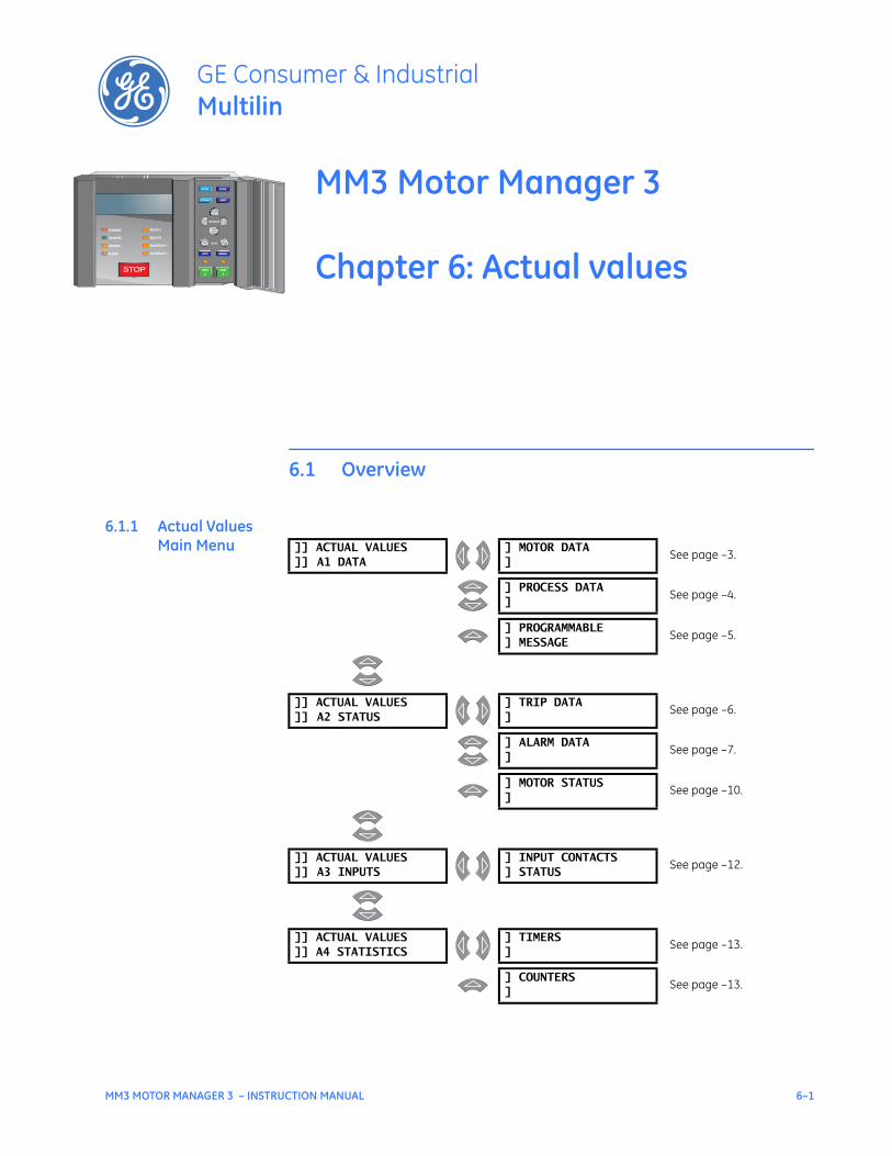
MM3 MOTOR MANAGER 3 – INSTRUCTION MANUAL 6–1
MM3 Motor Manager 3
Chapter 6: Actual values
GE Consumer & IndustrialMultilin
STOP
RUNNING RELAY ARELAY A
STOPPED RELAY BRELAY B
TRIPPED AUX RELAY 1AUX RELAY 1
ALARM AUX RELAY 2AUX RELAY 2
VALUE
MESSAGE
AUTO MANUAL
STORE
RESET
ACTUAL
SETPOINT
START
A
START
A
START
B
START
B
Actual values
6.1 Overview
6.1.1 Actual Values Main Menu ]] ACTUAL VALUES
]] A1 DATA] MOTOR DATA]
See page –3.
] PROCESS DATA]
See page –4.
] PROGRAMMABLE] MESSAGE
See page –5.
]] ACTUAL VALUES]] A2 STATUS
] TRIP DATA]
See page –6.
] ALARM DATA]
See page –7.
] MOTOR STATUS]
See page –10.
]] ACTUAL VALUES]] A3 INPUTS
] INPUT CONTACTS] STATUS
See page –12.
]] ACTUAL VALUES]] A4 STATISTICS
] TIMERS]
See page –13.
] COUNTERS]
See page –13.

6–2 MM3 MOTOR MANAGER 3 – INSTRUCTION MANUAL
OVERVIEW CHAPTER 6: ACTUAL VALUES
This chapter shows the actual messages displayed on the front panel of the MM3 Motor Manager 3. Quantities shown are typical values only. Different quantities will be displayed in each particular application.
When finished viewing a message in a particular section, press MESSAGE RIGHT to view the next line. When the last line of a section is reached, press MESSAGE DOWN to view the next section in the page. When the last line of the last section within a page is reached, press ACTUAL to select the next page.
6.1.2 Default Message Selection
Up to five default messages can be selected to scan sequentially when the motor is running and the MM3 Motor Manager 3 is left unattended. If no keys are pressed for 2 minutes and the motor is running, then the currently displayed message will automatically be overwritten by the first default message. After 3 seconds, the next default message in the sequence will display if more than one is selected. Alarm and trip messages override the default message display. Any actual value or setpoint can be selected as a default message. For example, the MM3 Motor Manager 3 could be programmed to display these messages in sequence: three-phase current, ground current, motor status, motor current as a percentage of full load, and analog input.
Messages are displayed in the order they are selected. To add a default message, use the message keys to display any actual values or setpoints message to be added to the default queue. Press the STORE key twice in rapid succession. The display will prompt “TO ADD THIS MESSAGE PRESS STORE”.
Press STORE again. The display confirms that the default message has been added. If five default messages are already selected, the first message is erased and the new message added to the end of the queue.
To delete a default message, wait for 2 minutes and note the messages that are displayed in sequence. Use the message keys to display the default message to be erased. Press STORE then RESET in rapid succession. The display prompts “TO DELETE THIS MESSAGE PRESS STORE”.
Press the STORE key. The display confirms that the default message has been deleted. If the message was not a current default message, the display will read “NOT A SELECTED DEFAULT MESSAGE”.
6.1.3 Actual Values Abbreviations
The following abbreviations are used in the actual values messages.
• A, AMPS: amperes
• kW: kilowatts
• kWhr: kilowatt-hours
• MIN: minutes
• N/O: normally open
• O/L: overload
• s: seconds
NOTE
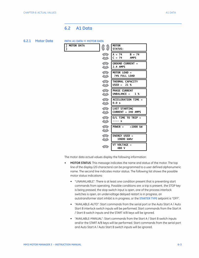
CHAPTER 6: ACTUAL VALUES A1 DATA
MM3 MOTOR MANAGER 3 – INSTRUCTION MANUAL 6–3
6.2 A1 Data
6.2.1 Motor Data PATH: A1 DATA MOTOR DATA
The motor data actual values display the following information:
• MOTOR STATUS: This message indicates the name and status of the motor. The top line of the display (20 characters) can be programmed to a user defined alphanumeric name. The second line indicates motor status. The following list shows the possible motor status indications:
• “UNAVAILABLE”: There is at least one condition present that is preventing start commands from operating. Possible conditions are: a trip is present, the STOP key is being pressed, the stop switch input is open, one of the process interlock switches is open, an undervoltage delayed restart is in progress, an autotransformer start inhibit is in progress, or the STARTER TYPE setpoint is “OFF”.
• “AVAILABLE-AUTO”: Start commands from the serial port or the Auto Start A / Auto Start B interlock switch inputs will be performed. Start commands from the Start A / Start B switch inputs and the START A/B keys will be ignored.
• “AVAILABLE-MANUAL”: Start commands from the Start A / Start B switch inputs and/or the START A/B keys will be performed. Start commands from the serial port and Auto Start A / Auto Start B switch inputs will be ignored.
] MOTOR DATA]
MOTORSTATUS:
A = 74 B = 74C = 74 AMPS
GROUND CURRENT =2.4 AMPS
MOTOR LOAD =74% FULL LOAD
THERMAL CAPACITYUSED = 21 %
PHASE CURRENTUNBALANCE = 1 %
ACCELERATION TIME =0.0 s
LAST STARTINGCURRENT = 340 AMPS
O/L TIME TO TRIP =---- s
POWER = +1000 kW
ENERGY USED =10600 kWhr
VT VOLTAGE =480 V
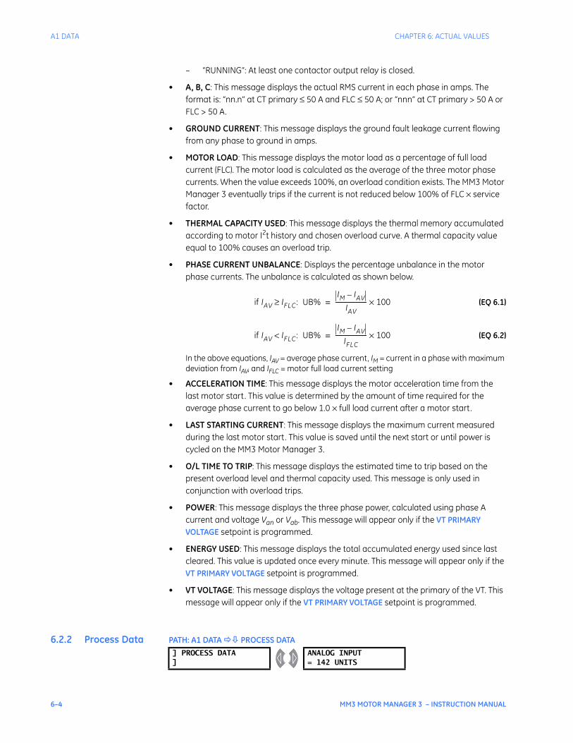
6–4 MM3 MOTOR MANAGER 3 – INSTRUCTION MANUAL
A1 DATA CHAPTER 6: ACTUAL VALUES
– “RUNNING”: At least one contactor output relay is closed.
• A, B, C: This message displays the actual RMS current in each phase in amps. The format is: “nn.n” at CT primary ≤ 50 A and FLC ≤ 50 A; or “nnn” at CT primary > 50 A or FLC > 50 A.
• GROUND CURRENT: This message displays the ground fault leakage current flowing from any phase to ground in amps.
• MOTOR LOAD: This message displays the motor load as a percentage of full load current (FLC). The motor load is calculated as the average of the three motor phase currents. When the value exceeds 100%, an overload condition exists. The MM3 Motor Manager 3 eventually trips if the current is not reduced below 100% of FLC × service factor.
• THERMAL CAPACITY USED: This message displays the thermal memory accumulated according to motor I2t history and chosen overload curve. A thermal capacity value equal to 100% causes an overload trip.
• PHASE CURRENT UNBALANCE: Displays the percentage unbalance in the motor phase currents. The unbalance is calculated as shown below.
(EQ 6.1)
(EQ 6.2)
In the above equations, IAV = average phase current, IM = current in a phase with maximum deviation from IAV, and IFLC = motor full load current setting
• ACCELERATION TIME: This message displays the motor acceleration time from the last motor start. This value is determined by the amount of time required for the average phase current to go below 1.0 × full load current after a motor start.
• LAST STARTING CURRENT: This message displays the maximum current measured during the last motor start. This value is saved until the next start or until power is cycled on the MM3 Motor Manager 3.
• O/L TIME TO TRIP: This message displays the estimated time to trip based on the present overload level and thermal capacity used. This message is only used in conjunction with overload trips.
• POWER: This message displays the three phase power, calculated using phase A current and voltage Van or Vab. This message will appear only if the VT PRIMARY VOLTAGE setpoint is programmed.
• ENERGY USED: This message displays the total accumulated energy used since last cleared. This value is updated once every minute. This message will appear only if the VT PRIMARY VOLTAGE setpoint is programmed.
• VT VOLTAGE: This message displays the voltage present at the primary of the VT. This message will appear only if the VT PRIMARY VOLTAGE setpoint is programmed.
6.2.2 Process Data PATH: A1 DATA PROCESS DATA
if IAV IFLC≥ : UB%IM IAV–
IAV--------------------- 100×=
if IAV IFLC< : UB%IM IAV–
IFLC--------------------- 100×=
] PROCESS DATA]
ANALOG INPUT= 142 UNITS

CHAPTER 6: ACTUAL VALUES A1 DATA
MM3 MOTOR MANAGER 3 – INSTRUCTION MANUAL 6–5
This message displays the 4 to 20 mA analog input value scaled to the minimum and maximum values as specified in setpoints. The analog input name and units are user-definable in the setpoints area.
6.2.3 Programmable Message
PATH: A1 DATA PROGRAMMABLE MESSAGE
This message contains 40 characters of user programmable text. The text can be entered in the S1 CONFIGURATION PROGRAMMABLE MESSAGE menu. See Programmable Message on page 5–10 for details.
] PROGRAMMABLE] MESSAGE
PROGRAMMABLE MESSAGESAMPLE TEXT
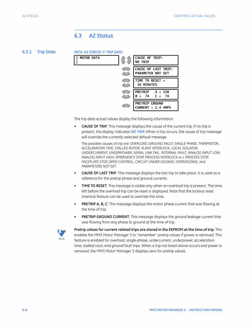
6–6 MM3 MOTOR MANAGER 3 – INSTRUCTION MANUAL
A2 STATUS CHAPTER 6: ACTUAL VALUES
6.3 A2 Status
6.3.1 Trip Data PATH: A2 STATUS TRIP DATA
The trip data actual values display the following information:
• CAUSE OF TRIP: This message displays the cause of the current trip. If no trip is present, the display indicates NO TRIP. When a trip occurs, the cause of trip message will override the currently selected default message.
The possible causes of trip are: OVERLOAD, GROUND FAULT, SINGLE PHASE, THERMISTOR, ACCELERATION TIME, STALLED ROTOR, PLANT INTERLOCK, LOCAL ISOLATOR, UNDERCURRENT, UNDERPOWER, SERIAL LINK FAIL, INTERNAL FAULT, ANALOG INPUT LOW, ANALOG INPUT HIGH, EMERGENCY STOP, PROCESS INTERLOCK A-J, PROCESS STOP, FACEPLATE STOP, OPEN CONTROL, CIRCUIT UNDER VOLTAGE, OVERVOLTAGE, and PARAMETERS NOT SET
• CAUSE OF LAST TRIP: This message displays the last trip to take place. It is used as a reference for the pretrip phase and ground currents.
• TIME TO RESET: This message is visible only when an overload trip is present. The time left before the overload trip can be reset is displayed. Note that the lockout reset interlock feature can be used to override this time.
• PRETRIP A, B, C: This message displays the motor phase current that was flowing at the time of trip.
• PRETRIP GROUND CURRENT: This message displays the ground leakage current that was flowing from any phase to ground at the time of trip.
Pretrip values for current related trips are stored in the EEPROM at the time of trip. This enables the MM3 Motor Manager 3 to “remember” pretrip values if power is removed. This feature is enabled for overload, single-phase, undercurrent, underpower, acceleration time, stalled rotor, and ground fault trips. When a trip not listed above occurs and power is removed, the MM3 Motor Manager 3 displays zero for pretrip values.
] MOTOR DATA]
CAUSE OF TRIP:NO TRIP
CAUSE OF LAST TRIP:PARAMETER NOT SET
TIME TO RESET =10 MINUTES
PRETRIP A = 238B = 74 C = 74
PRETRIP GROUNDCURRENT = 2.4 AMPS
NOTE
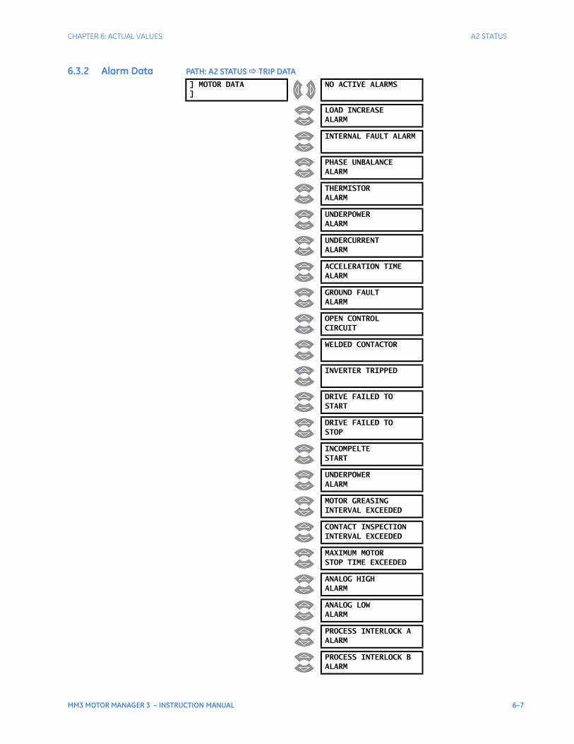
CHAPTER 6: ACTUAL VALUES A2 STATUS
MM3 MOTOR MANAGER 3 – INSTRUCTION MANUAL 6–7
6.3.2 Alarm Data PATH: A2 STATUS TRIP DATA] MOTOR DATA]
NO ACTIVE ALARMS
LOAD INCREASEALARM
INTERNAL FAULT ALARM
PHASE UNBALANCEALARM
THERMISTORALARM
UNDERPOWERALARM
UNDERCURRENTALARM
ACCELERATION TIMEALARM
GROUND FAULTALARM
OPEN CONTROLCIRCUIT
WELDED CONTACTOR
INVERTER TRIPPED
DRIVE FAILED TOSTART
DRIVE FAILED TOSTOP
INCOMPELTESTART
UNDERPOWERALARM
MOTOR GREASINGINTERVAL EXCEEDED
CONTACT INSPECTIONINTERVAL EXCEEDED
MAXIMUM MOTORSTOP TIME EXCEEDED
ANALOG HIGHALARM
ANALOG LOWALARM
PROCESS INTERLOCK AALARM
PROCESS INTERLOCK BALARM
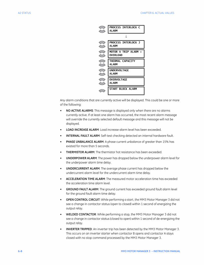
6–8 MM3 MOTOR MANAGER 3 – INSTRUCTION MANUAL
A2 STATUS CHAPTER 6: ACTUAL VALUES
Any alarm conditions that are currently active will be displayed. This could be one or more of the following:
• NO ACTIVE ALARMS: This message is displayed only when there are no alarms currently active. If at least one alarm has occurred, the most recent alarm message will override the currently selected default message and this message will not be displayed.
• LOAD INCREASE ALARM: Load increase alarm level has been exceeded.
• INTERNAL FAULT ALARM: Self-test checking detected an internal hardware fault.
• PHASE UNBALANCE ALARM: A phase current unbalance of greater than 15% has existed for more than 5 seconds.
• THERMISTOR ALARM: The thermistor hot resistance has been exceeded.
• UNDERPOWER ALARM: The power has dropped below the underpower alarm level for the underpower alarm time delay.
• UNDERCURRENT ALARM: The average phase current has dropped below the undercurrent alarm level for the undercurrent alarm time delay.
• ACCELERATION TIME ALARM: The measured motor acceleration time has exceeded the acceleration time alarm level.
• GROUND FAULT ALARM: The ground current has exceeded ground fault alarm level for the ground fault alarm time delay.
• OPEN CONTROL CIRCUIT: While performing a start, the MM3 Motor Manager 3 did not see a change in contactor status (open to closed) within 1 second of energizing the output relay.
• WELDED CONTACTOR: While performing a stop, the MM3 Motor Manager 3 did not see a change in contactor status (closed to open) within 1 second of de-energizing the output relay.
• INVERTER TRIPPED: An inverter trip has been detected by the MM3 Motor Manager 3. This occurs on an inverter starter when contactor B opens and contactor A stays closed with no stop command processed by the MM3 Motor Manager 3.
PROCESS INTERLOCK CALARM
↓
PROCESS INTERLOCK JALARM
MOTOR A TRIP ALARM =OVERLOAD
THERMAL CAPACITYALARM
UNDERVOLTAGEALARM
OVERVOLTAGEALARM
START BLOCK ALARM

CHAPTER 6: ACTUAL VALUES A2 STATUS
MM3 MOTOR MANAGER 3 – INSTRUCTION MANUAL 6–9
• DRIVE FAILED TO START: An inverter starter has failed to complete a start sequence. This occurs on an inverter starter when, during a start sequence, contactor A closes as expected but contactor B fails to close.
• DRIVE FAILED TO STOP: An inverter starter has failed to complete its stop sequence. This occurs on an inverter starter when contactor B fails to open during a stop sequence.
• INCOMPLETE START: An autotransformer starter has failed to complete its start sequence. This occurs on an autotransformer starter start sequence when contactor A closes as expected but contactor B fails to close.
• UNDERPOWER ALARM: The power has dropped below the underpower alarm level for the underpower alarm time delay.
• MOTOR GREASING INTERVAL EXCEEDED: The motor greasing interval time has been exceeded.
• CONTACT INSPECTION INTERVAL EXCEEDED: The number of contactor operations has exceeded the contactor inspection interval alarm count.
• MAXIMUM MOTOR STOP TIME EXCEEDED: The time that the motor has remained stopped has exceeded the maximum motor stopped time alarm level. This can be cleared by starting the motor.
• ANALOG HIGH ALARM: The analog input value has exceeded the analog input high alarm level for the analog input high alarm time delay.
• ANALOG LOW ALARM: The analog input value has dropped below the analog input low alarm level for the analog input low alarm time delay.
• PROCESS INTERLOCK A to PROCESS INTERLOCK J: An open process interlock switch input (A through J) has been detected.
• MOTOR A TRIP ALARM: A duty/standby starter type motor has tripped. The cause of the trip is displayed on the bottom line.
• THERMAL CAPACITY ALARM: The thermal capacity used has exceeded the alarm level.
• UNDERVOLTAGE ALARM: The primary voltage measurement has dropped below the alarm level.
• OVERVOLTAGE ALARM: The primary voltage measurement has exceeded the alarm level.
• START BLOCK ALARM: A start block is in effect.
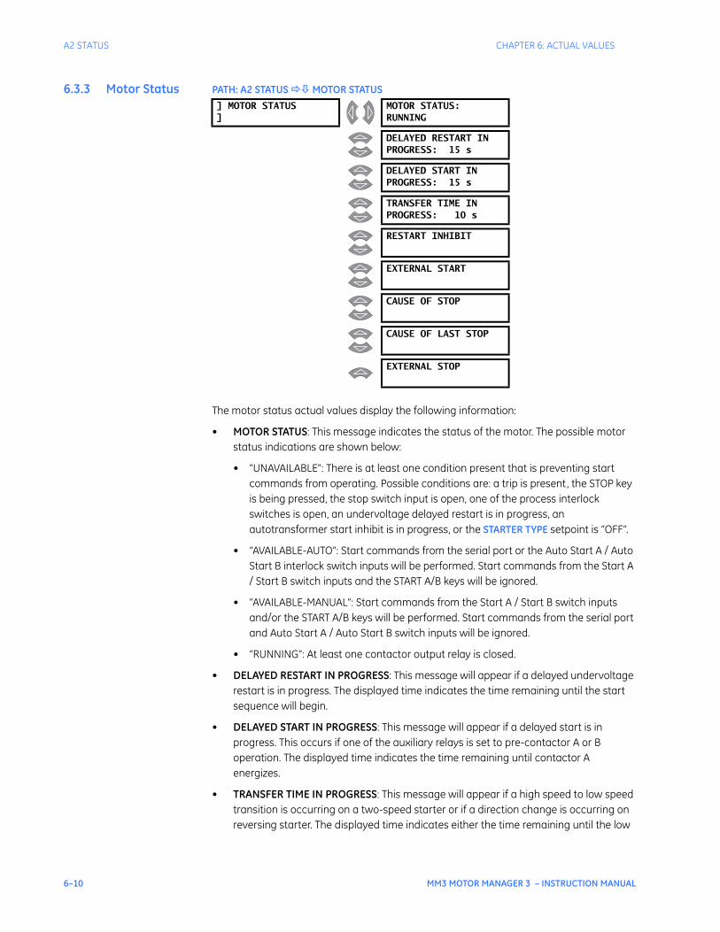
6–10 MM3 MOTOR MANAGER 3 – INSTRUCTION MANUAL
A2 STATUS CHAPTER 6: ACTUAL VALUES
6.3.3 Motor Status PATH: A2 STATUS MOTOR STATUS
The motor status actual values display the following information:
• MOTOR STATUS: This message indicates the status of the motor. The possible motor status indications are shown below:
• “UNAVAILABLE”: There is at least one condition present that is preventing start commands from operating. Possible conditions are: a trip is present, the STOP key is being pressed, the stop switch input is open, one of the process interlock switches is open, an undervoltage delayed restart is in progress, an autotransformer start inhibit is in progress, or the STARTER TYPE setpoint is “OFF”.
• “AVAILABLE-AUTO”: Start commands from the serial port or the Auto Start A / Auto Start B interlock switch inputs will be performed. Start commands from the Start A / Start B switch inputs and the START A/B keys will be ignored.
• “AVAILABLE-MANUAL”: Start commands from the Start A / Start B switch inputs and/or the START A/B keys will be performed. Start commands from the serial port and Auto Start A / Auto Start B switch inputs will be ignored.
• “RUNNING”: At least one contactor output relay is closed.
• DELAYED RESTART IN PROGRESS: This message will appear if a delayed undervoltage restart is in progress. The displayed time indicates the time remaining until the start sequence will begin.
• DELAYED START IN PROGRESS: This message will appear if a delayed start is in progress. This occurs if one of the auxiliary relays is set to pre-contactor A or B operation. The displayed time indicates the time remaining until contactor A energizes.
• TRANSFER TIME IN PROGRESS: This message will appear if a high speed to low speed transition is occurring on a two-speed starter or if a direction change is occurring on reversing starter. The displayed time indicates either the time remaining until the low
] MOTOR STATUS]
MOTOR STATUS:RUNNING
DELAYED RESTART INPROGRESS: 15 s
DELAYED START INPROGRESS: 15 s
TRANSFER TIME INPROGRESS: 10 s
RESTART INHIBIT
EXTERNAL START
CAUSE OF STOP
CAUSE OF LAST STOP
EXTERNAL STOP

CHAPTER 6: ACTUAL VALUES A2 STATUS
MM3 MOTOR MANAGER 3 – INSTRUCTION MANUAL 6–11
speed output relay (contactor A) will energize, or the time remaining until the forward output relay (contactor A) or the reverse output relay (contactor B) will energize.
• RESTART INHIBIT: This message will appear when an autotransformer start is inhibited. The restart inhibit time is determined from the autotransformer starts per hour setpoint.
• EXTERNAL START: This message will appear if the contactor closed without receiving a start command from the MM3 Motor Manager 3. The MM3 Motor Manager 3 will close the corresponding output relay to seal in the contactor.
• CAUSE OF STOP: This message will appear to indicate the cause of the current stop condition.
• CAUSE OF LAST STOP: This message indicates the cause of the last stop operation.
• EXTERNAL STOP: This message indicates that the stop operation was caused externally to the MM3 Motor Manager 3; that is, the contactor coil de-energized
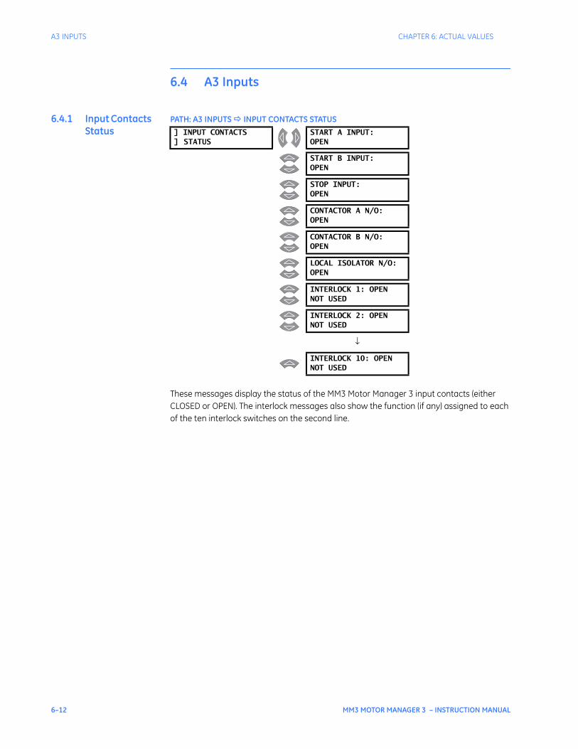
6–12 MM3 MOTOR MANAGER 3 – INSTRUCTION MANUAL
A3 INPUTS CHAPTER 6: ACTUAL VALUES
6.4 A3 Inputs
6.4.1 Input Contacts Status
PATH: A3 INPUTS INPUT CONTACTS STATUS
These messages display the status of the MM3 Motor Manager 3 input contacts (either CLOSED or OPEN). The interlock messages also show the function (if any) assigned to each of the ten interlock switches on the second line.
] INPUT CONTACTS] STATUS
START A INPUT:OPEN
START B INPUT:OPEN
STOP INPUT:OPEN
CONTACTOR A N/O:OPEN
CONTACTOR B N/O:OPEN
LOCAL ISOLATOR N/O:OPEN
INTERLOCK 1: OPENNOT USED
INTERLOCK 2: OPENNOT USED
↓
INTERLOCK 10: OPENNOT USED
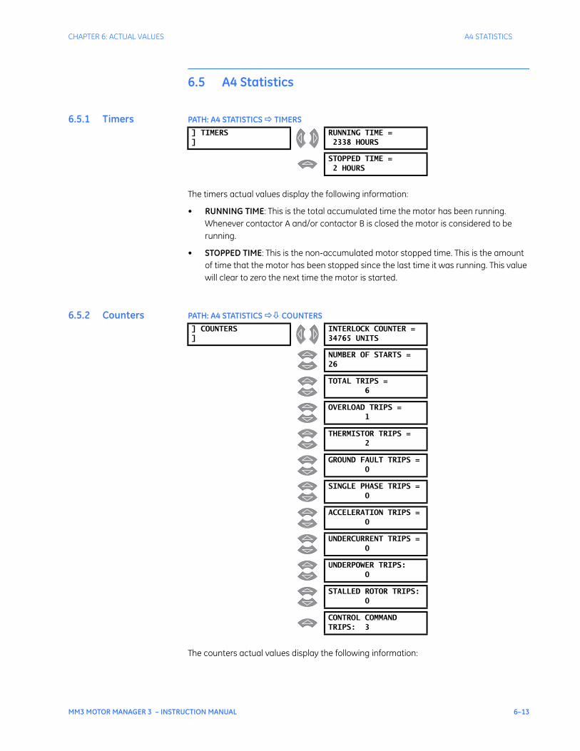
CHAPTER 6: ACTUAL VALUES A4 STATISTICS
MM3 MOTOR MANAGER 3 – INSTRUCTION MANUAL 6–13
6.5 A4 Statistics
6.5.1 Timers PATH: A4 STATISTICS TIMERS
The timers actual values display the following information:
• RUNNING TIME: This is the total accumulated time the motor has been running. Whenever contactor A and/or contactor B is closed the motor is considered to be running.
• STOPPED TIME: This is the non-accumulated motor stopped time. This is the amount of time that the motor has been stopped since the last time it was running. This value will clear to zero the next time the motor is started.
6.5.2 Counters PATH: A4 STATISTICS COUNTERS
The counters actual values display the following information:
] TIMERS]
RUNNING TIME =2338 HOURS
STOPPED TIME =2 HOURS
] COUNTERS]
INTERLOCK COUNTER =34765 UNITS
NUMBER OF STARTS =26
TOTAL TRIPS =6
OVERLOAD TRIPS =1
THERMISTOR TRIPS =2
GROUND FAULT TRIPS =0
SINGLE PHASE TRIPS =0
ACCELERATION TRIPS =0
UNDERCURRENT TRIPS =0
UNDERPOWER TRIPS:0
STALLED ROTOR TRIPS:0
CONTROL COMMANDTRIPS: 3
6–14 MM3 MOTOR MANAGER 3 – INSTRUCTION MANUAL
A4 STATISTICS CHAPTER 6: ACTUAL VALUES
• INTERLOCK COUNTER: This is the total number of switch closures read by the MM3 Motor Manager 3 on a programmable input that has been configured to “INTERLOCK COUNTER”.
• NUMBER OF STARTS: This is the total number of contactor operations. When the MM3 Motor Manager 3 receives feedback into either contactor status input to confirm that one of the main contactors have closed, this counter will increment.
• TOTAL TRIPS: When the MM3 Motor Manager 3 trips for any reason, this value is incremented. It is the sum of all of the individual causes of trip.
• OVERLOAD TRIPS: This value is incremented when an overload trip occurs.
• THERMISTOR TRIPS: This value is incremented when a thermistor trip occurs.
• GROUND FAULT TRIPS: This value is incremented when a ground fault trip occurs.
• SINGLE PHASE TRIPS: This value is incremented when a single phase trip occurs.
• ACCELERATION TRIPS: This value is incremented when an acceleration trip occurs.
• UNDERCURRENT TRIPS: This value is incremented when an undercurrent trip occurs.
• UNDERPOWER TRIPS: This value is incremented when an underpower trip occurs.
• STALLED ROTOR TRIPS: This value is incremented when a stalled rotor trip occurs.
• CONTROL COMMAND TRIPS: If a control trip occurs, this value is incremented (i.e. plant interlock, local isolator etc.).

MM3 MOTOR MANAGER 3 – INSTRUCTION MANUAL 7–1
MM3 Motor Manager 3
Chapter 7: Testing
GE Consumer & IndustrialMultilin
STOP
RUNNING RELAY ARELAY A
STOPPED RELAY BRELAY B
TRIPPED AUX RELAY 1AUX RELAY 1
ALARM AUX RELAY 2AUX RELAY 2
VALUE
MESSAGE
AUTO MANUAL
STORE
RESET
ACTUAL
SETPOINT
START
A
START
A
START
B
START
B
Testing
7.1 Injection Testing
7.1.1 Primary Injection Testing
Prior to MM3 Motor Manager 3 commissioning, complete system operation can be verified by injecting current through the phase and ground fault CTs. To accomplish this, a current injection test set is required.
Operation of the entire MM3 Motor Manager 3 control/protection system, except the phase and ground fault CTs, can be checked by applying input signals to the MM3 Motor Manager 3 from a secondary injection test set as described in this chapter.
7.1.2 Secondary Injection Testing
The figure below shows a simple, single-phase secondary injection test circuit that can be used to perform the tests described in this chapter. Tests should be performed to verify the correct operation and wiring. All functions are firmware driven and this testing is required only to verify correct firmware/hardware interaction.
The tests described in the following sections can be repeated and modified using setpoints and current levels more closely suited to the actual installation.
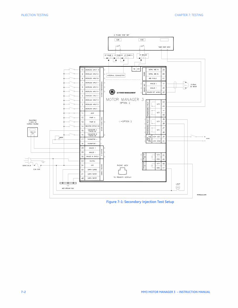
7–2 MM3 MOTOR MANAGER 3 – INSTRUCTION MANUAL
INJECTION TESTING CHAPTER 7: TESTING
Figure 7-1: Secondary Injection Test Setup
GE POWER MANAGEMENT

CHAPTER 7: TESTING FUNCTIONAL TESTS
MM3 MOTOR MANAGER 3 – INSTRUCTION MANUAL 7–3
7.2 Functional Tests
7.2.1 Phase Current Functions
Any phase current protection is based on the ability of the MM3 Motor Manager 3 to read phase input currents accurately. Make the following settings:
S2 PROTECTION MOTOR PROTECTION THERMAL FULL LOAD CURRENT: “100 A”S1 CONFIGURATION STARTER STARTER TYPE: “FV NON REVERSING”
To determine if the relay is reading the proper input current values, inject different phase currents into the CT inputs and view the current readings in A1 DATA MOTOR DATA. The displayed current should be equal to the actual injected current.
Phase current values will be displayed even if the motor status is stopped; that is, contactor A has not been activated by a start command. Very low currents are displayed as 0 A.
Once the accuracy of the phase CT inputs has been established, various phase alarm and trip condition tests can be performed by altering setpoints and injected phase currents.
To simulate an overload condition, enter the S2 PROTECTION MOTOR PROTECTION THERMAL menu and set OVERLOAD CURVE NUMBER to “4” and FULL LOAD CURRENT to “50 A”. PHASE CT PRIMARY AMPS should be set to “100 A”. Close the start A input and note that the Running LED goes on. Inject a current of 10 A into all three phases. The relay will display a current value of:
displayed current = actual injected current × 100/5 = 10 × 100 / 5 = 200 A.
This represents 4 times the phase FULL LOAD CURRENT setpoint. Therefore, based on a 400% overload and curve #4, contactor A will change state 23 seconds after the overload is first applied. When this occurs, the Running LED turns off and the Tripped and Stopped LEDs are lit . After the trip has occurred, use the A1 DATA MOTOR DATA actual values to verify that the thermal capacity used is now 100%. Press the RESET key to reset the MM3 Motor Manager 3.
To prepare the MM3 Motor Manager 3 to simulate an unbalance alarm, make the following settings. In the S2 PROTECTION MOTOR PROTECTION OPTIONS menu, set:
PHASE UNBALANCE ALARM: “ENABLE”
In the S4 CONTROL AUX RELAY 1 CONFIG menu, set:
AUX RELAY 1 FUNCTION: “ALARMS”
In the S4 CONTROL AUX RELAY 2 CONFIG menu, set:
AUX RELAY 2 FUNCTION: “TRIPS”
Inject 5.0 A into all three phase CTs. The MM3 Motor Manager 3 displays a balanced phase current of 100 A for each phase. While still viewing actual values, slowly begin decreasing phase 1 current until the UNBALANCE ALARM message comes on. Auxiliary relay 1 should energize when the alarm is present. Unbalance is calculated as follows:
For average currents greater than motor full load:
(EQ 7.1)In Iav–
Iav---------------- 15% (alarm) 30% trip>
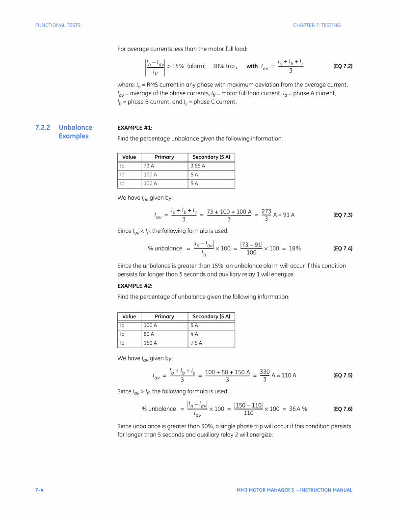
7–4 MM3 MOTOR MANAGER 3 – INSTRUCTION MANUAL
FUNCTIONAL TESTS CHAPTER 7: TESTING
For average currents less than the motor full load:
, with (EQ 7.2)
where: In = RMS current in any phase with maximum deviation from the average current, Iav = average of the phase currents, Ifl = motor full load current, Ia = phase A current, Ib = phase B current, and Ic = phase C current.
7.2.2 Unbalance Examples
EXAMPLE #1:
Find the percentage unbalance given the following information:
We have Iav given by:
(EQ 7.3)
Since Iav < Ifl, the following formula is used:
(EQ 7.4)
Since the unbalance is greater than 15%, an unbalance alarm will occur if this condition persists for longer than 5 seconds and auxiliary relay 1 will energize.
EXAMPLE #2:
Find the percentage of unbalance given the following information:
We have Iav given by:
(EQ 7.5)
Since Iav > Ifl, the following formula is used:
(EQ 7.6)
Since unbalance is greater than 30%, a single phase trip will occur if this condition persists for longer than 5 seconds and auxiliary relay 2 will energize.
In Iav–
Ifl---------------- 15% (alarm) 30% trip> Iav
Ia Ib Ic+ +
3------------------------=
Value Primary Secondary (5 A)
Ia 73 A 3.65 A
Ib 100 A 5 A
Ic 100 A 5 A
Value Primary Secondary (5 A)
Ia 100 A 5 A
Ib 80 A 4 A
Ic 150 A 7.5 A
IavIa Ib Ic+ +
3------------------------ 73 100 100 A+ +
3------------------------------------------- 273
3--------- A = 91 A= = =
% unbalance In Iav–
If l------------------- 100× 73 91–
100--------------------- 100× 18%= = =
IavIa Ib Ic+ +
3------------------------ 100 80 150 A+ +
3------------------------------------------- 330
3--------- A = 110 A= = =
% unbalance In Iav–
Iav------------------- 100× 150 110–
110---------------------------- 100× 36.4 %= = =

CHAPTER 7: TESTING FUNCTIONAL TESTS
MM3 MOTOR MANAGER 3 – INSTRUCTION MANUAL 7–5
7.2.3 Ground Fault Current Functions
Test the ground fault CT (residual / 50:0.025) in a similar manner to phase currents for accuracy at various injected current levels. To check alarm and trip levels, make the following settings.
In the S1 CONFIGURATION CT/VT INPUTS menu, set:
GROUND FAULT CT INPUT: “RESIDUAL”
In the S2 PROTECTION MOTOR PROTECTION GROUND FAULT menu, set:
GROUND FAULT ALARM LEVEL: “40 %FLC”GROUND FAULT TRIP LEVEL: “80 %FLC”
In the S2 PROTECTION MOTOR PROTECTION THERMAL menu, set:
FULL LOAD CURRENT: “100 A”
While displaying the A1 DATA MOTOR DATA GROUND CURRENT actual value, begin injecting current into the 5 A ground fault CT input. The Alarm LED lights and auxiliary relay 1 changes state at 40 A corresponding to the 40% FLC alarm setting. Change the display back to GROUND CURRENT and continue increasing injected secondary current. When the measured ground current reaches 80 A, a ground fault trip occurs. This trip causes the MM3 Motor Manager 3 to change its indicators and output relay status. The Running LED turns off, the Tripped and Stopped LEDs turn on, and the contactor A relay de-energizes. Auxiliary relay 1 remains energized as long as the alarm is present and auxiliary relay 2 energizes after the ground fault trip. The MM3 Motor Manager 3 displays a ground fault trip message. Turn the ground fault current off and press the reset key to reset the trip.
7.2.4 Input Functions
Operation of each MM3 Motor Manager 3 switch input can be verified on the display. Go to A3 INPUTS INPUT CONTACT STATUS menu view the status of each input one at a time. Open and close each switch input and note that the display reflects the present status of the input terminals. The status is shown as either “OPEN” or “CLOSED”.
7.2.5 Thermistor Input Tests
Begin testing by storing the following thermistor values. In the S1 CONFIGURATION THERMISTOR menu, set
HOT RESISTANCE: “30 kOHMS”COLD RESISTANCE: “0.1 kOHMS”THERMISTOR ALARM: “ENABLE”THERMISTOR TRIP: “DISABLE”
Place a variable 50 K potentiometer or resistance box across thermistor terminals 17 and 18 as shown in Secondary Injection Test Setup on page 7–2. With the input resistance set to zero, start increasing the resistance until a thermistor alarm occurs. Verify that the Alarm LED becomes lit and a THERMISTOR ALARM message is displayed. Use an ohmmeter to verify that the thermistor resistance agrees with the THERMISTOR HOT setpoint value.
The thermistor will have to be removed from the MM3 Motor Manager 3 to accurately measure its resistance. When the resistance has decreased below the COLD RESISTANCE setpoint value, the alarm will disappear.
To check the thermistor trip function, enable the thermistor trip by making the following settings changes in the S1 CONFIGURATION THERMISTOR menu:
THERMISTOR ALARM: “DISABLE”THERMISTOR TRIP: “ENABLE”
NOTE

7–6 MM3 MOTOR MANAGER 3 – INSTRUCTION MANUAL
FUNCTIONAL TESTS CHAPTER 7: TESTING
With the thermistor resistance initially set to zero, begin increasing resistance until a thermistor trip occurs. Note that the Tripped and Stopped LEDs are lit , the contactor A relay has de-energized, the Running LED is off, and a THERMISTOR TRIP message is displayed. Use an ohmmeter to verify that the thermistor resistance value agrees with the THERMISTOR HOT setpoint value. Decrease the thermistor resistance below the THERMISTOR HOT value but not below the THERMISTOR COLD value. Press the RESET key and verify that the MM3 Motor Manager 3 still indicates a trip. Reduce thermistor resistance below the THERMISTOR COLD value. Press the RESET key again, noting that the Tripped LED turns off and the default display message returns. Issue a Start A command via the keypad or switch input and note that contactor A contacts now close and the Running LED is lit .
7.2.6 Power Fail Test To test the power fail circuit, connect the supply voltage to the MM3 Motor Manager 3 through a variac and begin decreasing control voltage. When the control voltage drops below 80 V for 120 V AC input or 150 V for 240 V AC input, the fault light comes on and the MM3 Motor Manager 3 ceases to operate. The MM3 Motor Manager 3 has insufficient voltage to continue accurately monitoring the motor. All output relays will change to their power off state. Decrease control voltage to zero and then return voltage to its normal operating level. Verify that the MM3 Motor Manager 3 resumes its normal operation. Check the power fail memory circuit by verifying that setpoints and statistical data have not been altered.
MM3 MOTOR MANAGER 3 – INSTRUCTION MANUAL 8–1
MM3 Motor Manager 3
Chapter 8: Communications
GE Consumer & IndustrialMultilin
STOP
RUNNING RELAY ARELAY A
STOPPED RELAY BRELAY B
TRIPPED AUX RELAY 1AUX RELAY 1
ALARM AUX RELAY 2AUX RELAY 2
VALUE
MESSAGE
AUTO MANUAL
STORE
RESET
ACTUAL
SETPOINT
START
A
START
A
START
B
START
B
Communications
8.1 MM3 Motor Manager 3 Modbus Protocol
8.1.1 Overview The MM3 Motor Manager 3 implements a subset of the Modicon Modbus RTU serial communication standard. The Modbus protocol is hardware-independent. That is, the physical layer can be any of a variety of standard hardware configurations. This includes RS232, RS422, RS485, fibre optics, etc. Modbus is a single master / multiple slave type of protocol suitable for a multi-drop configuration as provided by RS485 hardware. The MM3 Motor Manager 3 Modbus implementation employs two-wire RS485 hardware. Using RS485, up to 32 MM3 Motor Manager 3s can be daisy-chained together on a single communication channel.
The MM3 Motor Manager 3 is always a Modbus slave. They can not be programmed as Modbus masters. Computers or PLCs are commonly programmed as masters.
Modbus protocol exists in two versions: Remote Terminal Unit (RTU, binary) and ASCII. Only the RTU version is supported by the MM3 Motor Manager 3.
Both monitoring and control are possible using read and write register commands. Other commands are supported to provide additional functions.
8.1.2 Electrical Interface
The hardware or electrical interface in the MM3 Motor Manager 3 is two-wire RS485. In a two-wire link, data is transmitted and received over the same two wires. Although RS485 two wire communication is bidirectional, the data is never transmitted and received at the same time. This means that the data flow is half duplex.
RS485 lines should be connected in a daisy chain configuration with terminating networks installed at each end of the link (i.e. at the master end and at the slave farthest from the master). The terminating network should consist of a 120 Ω resistor in series with a 1 nF ceramic capacitor when used with Belden 9841 RS485 wire. Shielded wire should always
8–2 MM3 MOTOR MANAGER 3 – INSTRUCTION MANUAL
MM3 MOTOR MANAGER 3 MODBUS PROTOCOL CHAPTER 8: COMMUNICATIONS
be used to minimize noise. The shield should be connected to all of the MM3 Motor Manager 3s as well as the master, then grounded at one location only. This keeps the ground potential at the same level for all of the devices on the serial link.
Polarity is important in RS485 communications. The '+' (positive) terminals of every device must be connected together.
Refer to Serial Communication Port on page 2–4 for additional information.
8.1.3 Data Frame Format and Data Rate
One data frame of an asynchronous transmission to or from a MM3 Motor Manager 3 typically consists of 1 start bit, 8 data bits, and 1 stop bit. This produces a 10 bit data frame. This is important for transmission through modems at high bit rates (11 bit data frames are not supported by Hayes modems at bit rates of greater than 300 bps). The MM3 Motor Manager 3 has the capability of adding an odd or even parity bit if necessary.
Modbus protocol can be implemented at any standard communication speed. The MM3 Motor Manager 3 supports operation at 1200, 2400, 4800, 9600, 19200, and 57600 baud.
8.1.4 Data Packet Format
A complete request/response sequence consists of the following bytes (transmitted as separate data frames):
Master request transmission:
SLAVE ADDRESS: 1 byteFUNCTION CODE: 1 byteDATA: variable number of bytes depending on FUNCTION CODECRC: 2 bytes
Slave response transmission:
SLAVE ADDRESS: 1 byteFUNCTION CODE: 1 byteDATA: variable number of bytes depending on FUNCTION CODECRC: 2 bytes
The function of each of these bytes is explained below.
• Slave address: This is the first byte of every transmission. This byte represents the user-assigned address of the slave device that is to receive the message sent by the master. Each slave device must be assigned a unique address and only the addressed slave will respond to a transmission that starts with its address. In a master request transmission the slave address represents the address of the slave to which the request is being sent. In a slave response transmission the slave address represents the address of the slave that is sending the response.
A master transmission with a slave address of 0 indicates a broadcast command. Broadcast commands can be used only in certain situations; see Storing Addresses using the Broadcast Command on page 8–12 for additional details.
• Function code: This is the second byte of every transmission. Modbus defines function codes of 1 to 127. The MM3 Motor Manager 3 implements some of these functions. See Supported Modbus Functions on page 8–5 details of the supported function codes. In a master request transmission the function code tells the slave what action to perform. In a slave response transmission the function code tells the master what function was performed as requested. If the high order bit of the function code sent
NOTE
NOTE
CHAPTER 8: COMMUNICATIONS MM3 MOTOR MANAGER 3 MODBUS PROTOCOL
MM3 MOTOR MANAGER 3 – INSTRUCTION MANUAL 8–3
from the slave is a 1 (i.e. if the function code is > 127) then the slave did not perform the function as requested and is sending an error or exception response.
• Data: This will be a variable number of bytes depending on the function code. This may be actual values, setpoints, or addresses sent by the master to the slave or by the slave to the master. See Supported Modbus Functions on page 8–5 for a description of the supported functions and the data required for each.
• CRC: This is a two byte error checking code.
8.1.5 Error Checking The RTU version of Modbus includes a two byte CRC-16 (16 bit cyclic redundancy check) with every transmission. The CRC-16 algorithm essentially treats the entire data stream (data bits only; start, stop and parity ignored) as one continuous binary number. This number is first shifted left 16 bits and then divided by a characteristic polynomial (11000000000000101B). The 16 bit remainder of the division is appended to the end of the transmission, the most significant byte (MSB) first. The resulting message including CRC, when divided by the same polynomial at the receiver will give a zero remainder if no transmission errors have occurred.
If a MM3 Motor Manager 3 Modbus slave device receives a transmission in which an error is indicated by the CRC-16 calculation, the slave device will not respond to the transmission. A CRC-16 error indicates than one or more bytes of the transmission were received incorrectly and thus the entire transmission should be ignored in order to avoid the MM3 Motor Manager 3 performing any incorrect operation.
The CRC-16 calculation is an industry standard method used for error detection. An algorithm is included here to assist programmers in situations where no standard CRC-16 calculation routines are available.
CRC-16 Algorithm:
Once the following algorithm is complete, the working register “A” will contain the CRC value to be transmitted. Note that this algorithm requires the characteristic polynomial to be reverse bit ordered. The most significant bit of the characteristic polynomial is dropped since it does not affect the value of the remainder. The following symbols are used in the algorithm:
• —>: data transfer
• A: 16 bit working register
• AL: low order byte of A
• AH: high order byte of A
• CRC: 16-bit CRC-16 value
• i, j: loop counters
• (+): logical exclusive or operator
• Di: i-th data byte (i = 0 to N-1)
• G: 16 bit characteristic polynomial = 1010000000000001 with the most significant bit dropped and bit order reversed
• shr(x): shift right (the least significant bit of the low order byte of x shifts into a carry flag, a '0' is shifted into the most significant bit of the high order byte of x, all other bits shift right one location
8–4 MM3 MOTOR MANAGER 3 – INSTRUCTION MANUAL
MM3 MOTOR MANAGER 3 MODBUS PROTOCOL CHAPTER 8: COMMUNICATIONS
The algorithm is:
1. FFFF hex —> A
2. 0 —> i
3. 0 —> j
4. Di (+) AL —> AL
5. j + 1 —> j
6. shr(A)
7. is there a carry? If No, go to 8; If Yes, G (+) A —> A
8. is j = 8? If No, go to 5; If Yes, go to 9.
9. i + 1 —> i
10. is i = N? If No, go to 3; If Yes, go to 11.
11. A —> CRC
8.1.6 Timing Data packet synchronization is maintained by timing constraints. The receiving device must measure the time between the reception of characters. If 3.5 character times elapse without a new character or completion of the packet, then the communication link must be reset (i.e. all slaves start listening for a new transmission from the master). Thus at 9600 baud a delay of greater than 3.5 × 1 / 9600 × 10 × = × 3.65 × ms will cause the communication link to be reset.
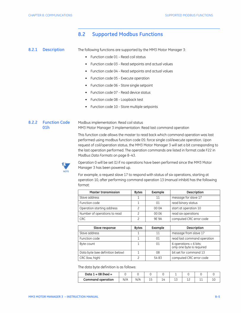
CHAPTER 8: COMMUNICATIONS SUPPORTED MODBUS FUNCTIONS
MM3 MOTOR MANAGER 3 – INSTRUCTION MANUAL 8–5
8.2 Supported Modbus Functions
8.2.1 Description The following functions are supported by the MM3 Motor Manager 3:
• Function code 01 - Read coil status
• Function code 03 - Read setpoints and actual values
• Function code 04 - Read setpoints and actual values
• Function code 05 - Execute operation
• Function code 06 - Store single setpoint
• Function code 07 - Read device status
• Function code 08 - Loopback test
• Function code 10 - Store multiple setpoints
8.2.2 Function Code 01h
Modbus implementation: Read coil statusMM3 Motor Manager 3 implementation: Read last command operation
This function code allows the master to read back which command operation was last performed using modbus function code 05: force single coil/execute operation. Upon request of coil/operation status, the MM3 Motor Manager 3 will set a bit corresponding to the last operation performed. The operation commands are listed in format code F22 in Modbus Data Formats on page 8–43.
Operation 0 will be set (1) if no operations have been performed since the MM3 Motor Manager 3 has been powered up.
For example, a request slave 17 to respond with status of six operations, starting at operation 10, after performing command operation 13 (manual inhibit) has the following format:
The data byte definition is as follows:
Master transmission Bytes Example Description
Slave address 1 11 message for slave 17
Function code 1 01 read binary status
Operation starting address 2 00 0A start at operation 10
Number of operations to read 2 00 06 read six operations
CRC 2 9E 9A computed CRC error code
Slave response Bytes Example Description
Slave address 1 11 message from slave 17
Function code 1 01 read last command operation
Byte count 1 01 6 operations = 6 bits:only one byte is required
Data byte (see definition below) 1 08 bit set for command 13
CRC (low, high) 2 54 83 computed CRC error code
Data 1 = 08 (hex) = 0 0 0 0 1 0 0 0
Command operation N/A N/A 15 14 13 12 11 10
NOTE
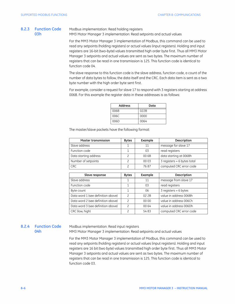
8–6 MM3 MOTOR MANAGER 3 – INSTRUCTION MANUAL
SUPPORTED MODBUS FUNCTIONS CHAPTER 8: COMMUNICATIONS
8.2.3 Function Code 03h
Modbus implementation: Read holding registersMM3 Motor Manager 3 implementation: Read setpoints and actual values
For the MM3 Motor Manager 3 implementation of Modbus, this command can be used to read any setpoints (holding registers) or actual values (input registers). Holding and input registers are 16-bit (two-byte) values transmitted high order byte first. Thus all MM3 Motor Manager 3 setpoints and actual values are sent as two bytes. The maximum number of registers that can be read in one transmission is 125. This function code is identical to function code 04.
The slave response to this function code is the slave address, function code, a count of the number of data bytes to follow, the data itself and the CRC. Each data item is sent as a two byte number with the high order byte sent first.
For example, consider a request for slave 17 to respond with 3 registers starting at address 006B. For this example the register data in these addresses is as follows:
The master/slave packets have the following format:
8.2.4 Function Code 04h
Modbus implementation: Read input registersMM3 Motor Manager 3 implementation: Read setpoints and actual values
For the MM3 Motor Manager 3 implementation of Modbus, this command can be used to read any setpoints (holding registers) or actual values (input registers). Holding and input registers are 16 bit (two byte) values transmitted high order byte first. Thus all MM3 Motor Manager 3 setpoints and actual values are sent as two bytes. The maximum number of registers that can be read in one transmission is 125. This function code is identical to function code 03.
Address Data
006B 022B
006C 0000
006D 0064
Master transmission Bytes Example Description
Slave address 1 11 message for slave 17
Function code 1 03 read registers
Data starting address 2 00 6B data starting at 006Bh
Number of setpoints 2 00 03 3 registers = 6 bytes total
CRC 2 76 87 computed CRC error code
Slave response Bytes Example Description
Slave address 1 11 message from slave 17
Function code 1 03 read registers
Byte count 1 06 3 registers = 6 bytes
Data word 1 (see definition above) 2 02 2B value in address 006Bh
Data word 2 (see definition above) 2 00 00 value in address 006Ch
Data word 3 (see definition above) 2 00 64 value in address 006Dh
CRC (low, high) 2 54 83 computed CRC error code
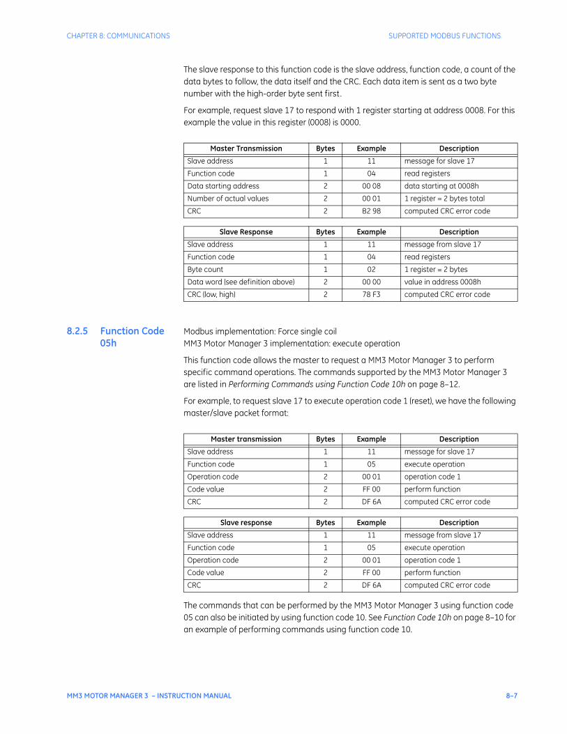
CHAPTER 8: COMMUNICATIONS SUPPORTED MODBUS FUNCTIONS
MM3 MOTOR MANAGER 3 – INSTRUCTION MANUAL 8–7
The slave response to this function code is the slave address, function code, a count of the data bytes to follow, the data itself and the CRC. Each data item is sent as a two byte number with the high-order byte sent first.
For example, request slave 17 to respond with 1 register starting at address 0008. For this example the value in this register (0008) is 0000.
8.2.5 Function Code 05h
Modbus implementation: Force single coilMM3 Motor Manager 3 implementation: execute operation
This function code allows the master to request a MM3 Motor Manager 3 to perform specific command operations. The commands supported by the MM3 Motor Manager 3 are listed in Performing Commands using Function Code 10h on page 8–12.
For example, to request slave 17 to execute operation code 1 (reset), we have the following master/slave packet format:
The commands that can be performed by the MM3 Motor Manager 3 using function code 05 can also be initiated by using function code 10. See Function Code 10h on page 8–10 for an example of performing commands using function code 10.
Master Transmission Bytes Example Description
Slave address 1 11 message for slave 17
Function code 1 04 read registers
Data starting address 2 00 08 data starting at 0008h
Number of actual values 2 00 01 1 register = 2 bytes total
CRC 2 B2 98 computed CRC error code
Slave Response Bytes Example Description
Slave address 1 11 message from slave 17
Function code 1 04 read registers
Byte count 1 02 1 register = 2 bytes
Data word (see definition above) 2 00 00 value in address 0008h
CRC (low, high) 2 78 F3 computed CRC error code
Master transmission Bytes Example Description
Slave address 1 11 message for slave 17
Function code 1 05 execute operation
Operation code 2 00 01 operation code 1
Code value 2 FF 00 perform function
CRC 2 DF 6A computed CRC error code
Slave response Bytes Example Description
Slave address 1 11 message from slave 17
Function code 1 05 execute operation
Operation code 2 00 01 operation code 1
Code value 2 FF 00 perform function
CRC 2 DF 6A computed CRC error code
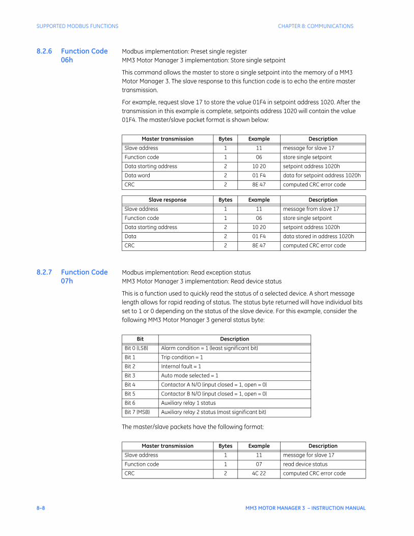
8–8 MM3 MOTOR MANAGER 3 – INSTRUCTION MANUAL
SUPPORTED MODBUS FUNCTIONS CHAPTER 8: COMMUNICATIONS
8.2.6 Function Code 06h
Modbus implementation: Preset single registerMM3 Motor Manager 3 implementation: Store single setpoint
This command allows the master to store a single setpoint into the memory of a MM3 Motor Manager 3. The slave response to this function code is to echo the entire master transmission.
For example, request slave 17 to store the value 01F4 in setpoint address 1020. After the transmission in this example is complete, setpoints address 1020 will contain the value 01F4. The master/slave packet format is shown below:
8.2.7 Function Code 07h
Modbus implementation: Read exception statusMM3 Motor Manager 3 implementation: Read device status
This is a function used to quickly read the status of a selected device. A short message length allows for rapid reading of status. The status byte returned will have individual bits set to 1 or 0 depending on the status of the slave device. For this example, consider the following MM3 Motor Manager 3 general status byte:
The master/slave packets have the following format:
Master transmission Bytes Example Description
Slave address 1 11 message for slave 17
Function code 1 06 store single setpoint
Data starting address 2 10 20 setpoint address 1020h
Data word 2 01 F4 data for setpoint address 1020h
CRC 2 8E 47 computed CRC error code
Slave response Bytes Example Description
Slave address 1 11 message from slave 17
Function code 1 06 store single setpoint
Data starting address 2 10 20 setpoint address 1020h
Data 2 01 F4 data stored in address 1020h
CRC 2 8E 47 computed CRC error code
Bit Description
Bit 0 (LSB) Alarm condition = 1 (least significant bit)
Bit 1 Trip condition = 1
Bit 2 Internal fault = 1
Bit 3 Auto mode selected = 1
Bit 4 Contactor A N/O (input closed = 1, open = 0)
Bit 5 Contactor B N/O (input closed = 1, open = 0)
Bit 6 Auxiliary relay 1 status
Bit 7 (MSB) Auxiliary relay 2 status (most significant bit)
Master transmission Bytes Example Description
Slave address 1 11 message for slave 17
Function code 1 07 read device status
CRC 2 4C 22 computed CRC error code

CHAPTER 8: COMMUNICATIONS SUPPORTED MODBUS FUNCTIONS
MM3 MOTOR MANAGER 3 – INSTRUCTION MANUAL 8–9
Slave response Bytes Example Description
Slave address 1 11 message from slave 17
Function code 1 07 read device status
Device status (see definition above) 2 2C status = 00101100 (binary)
CRC 2 22 28 computed CRC error code
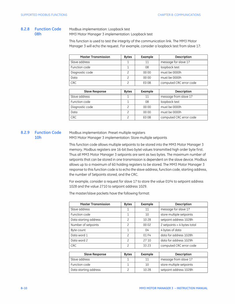
8–10 MM3 MOTOR MANAGER 3 – INSTRUCTION MANUAL
SUPPORTED MODBUS FUNCTIONS CHAPTER 8: COMMUNICATIONS
8.2.8 Function Code 08h
Modbus implementation: Loopback testMM3 Motor Manager 3 implementation: Loopback test
This function is used to test the integrity of the communication link. The MM3 Motor Manager 3 will echo the request. For example, consider a loopback test from slave 17:
8.2.9 Function Code 10h
Modbus implementation: Preset multiple registersMM3 Motor Manager 3 implementation: Store multiple setpoints
This function code allows multiple setpoints to be stored into the MM3 Motor Manager 3 memory. Modbus registers are 16-bit (two byte) values transmitted high order byte first. Thus all MM3 Motor Manager 3 setpoints are sent as two bytes. The maximum number of setpoints that can be stored in one transmission is dependent on the slave device. Modbus allows up to a maximum of 60 holding registers to be stored. The MM3 Motor Manager 3 response to this function code is to echo the slave address, function code, starting address, the number of Setpoints stored, and the CRC.
For example, consider a request for slave 17 to store the value 01F4 to setpoint address 1028 and the value 2710 to setpoint address 1029.
The master/slave packets have the following format:
Master Transmission Bytes Example Description
Slave address 1 11 message for slave 17
Function code 1 08 loopback test
Diagnostic code 2 00 00 must be 0000h
Data 2 00 00 must be 0000h
CRC 2 E0 0B computed CRC error code
Slave Response Bytes Example Description
Slave address 1 11 message from slave 17
Function code 1 08 loopback test
Diagnostic code 2 00 00 must be 0000h
Data 2 00 00 must be 0000h
CRC 2 E0 0B computed CRC error code
Master Transmission Bytes Example Description
Slave address 1 11 message for slave 17
Function code 1 10 store multiple setpoints
Data starting address 2 10 28 setpoint address 1028h
Number of setpoints 2 00 02 2 setpoints = 4 bytes total
Byte count 1 04 4 bytes of data
Data word 1 2 01 F4 data for address 1028h
Data word 2 2 27 10 data for address 1029h
CRC 2 33 23 computed CRC error code
Slave Response Bytes Example Description
Slave address 1 11 message from slave 17
Function code 1 10 store multiple setpoints
Data starting address 2 10 28 setpoint address 1028h
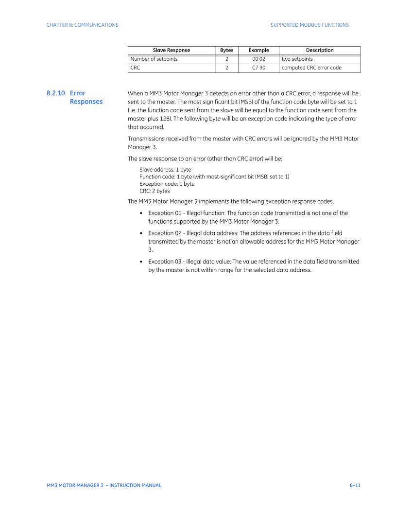
CHAPTER 8: COMMUNICATIONS SUPPORTED MODBUS FUNCTIONS
MM3 MOTOR MANAGER 3 – INSTRUCTION MANUAL 8–11
8.2.10 Error Responses
When a MM3 Motor Manager 3 detects an error other than a CRC error, a response will be sent to the master. The most significant bit (MSB) of the function code byte will be set to 1 (i.e. the function code sent from the slave will be equal to the function code sent from the master plus 128). The following byte will be an exception code indicating the type of error that occurred.
Transmissions received from the master with CRC errors will be ignored by the MM3 Motor Manager 3.
The slave response to an error (other than CRC error) will be:
Slave address: 1 byteFunction code: 1 byte (with most-significant bit (MSB) set to 1)Exception code: 1 byteCRC: 2 bytes
The MM3 Motor Manager 3 implements the following exception response codes.
• Exception 01 - Illegal function: The function code transmitted is not one of the functions supported by the MM3 Motor Manager 3.
• Exception 02 - Illegal data address: The address referenced in the data field transmitted by the master is not an allowable address for the MM3 Motor Manager 3.
• Exception 03 - Illegal data value: The value referenced in the data field transmitted by the master is not within range for the selected data address.
Number of setpoints 2 00 02 two setpoints
CRC 2 C7 90 computed CRC error code
Slave Response Bytes Example Description
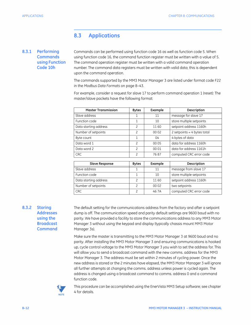
8–12 MM3 MOTOR MANAGER 3 – INSTRUCTION MANUAL
APPLICATIONS CHAPTER 8: COMMUNICATIONS
8.3 Applications
8.3.1 Performing Commands using Function Code 10h
Commands can be performed using function code 16 as well as function code 5. When using function code 16, the command function register must be written with a value of 5. The command operation register must be written with a valid command operation number. The command data registers must be written with valid data; this is dependent upon the command operation.
The commands supported by the MM3 Motor Manager 3 are listed under format code F22 in the Modbus Data Formats on page 8–43.
For example, consider a request for slave 17 to perform command operation 1 (reset): The master/slave packets have the following format:
8.3.2 Storing Addresses using the Broadcast Command
The default setting for the communications address from the factory and after a setpoint dump is off. The communication speed and parity default settings are 9600 baud with no parity. We have provided a facility to store the communications address to any MM3 Motor Manager 3 without using the keypad and display (typically chassis mount MM3 Motor Manager 3s).
Make sure the master is transmitting to the MM3 Motor Manager 3 at 9600 baud and no parity. After installing the MM3 Motor Manager 3 and ensuring communications is hooked up, cycle control voltage to the MM3 Motor Manager 3 you wish to set the address for. This will allow you to send a broadcast command with the new comms. address for the MM3 Motor Manager 3. The address must be set within 2 minutes of cycling power. Once the new address is stored or the 2 minutes have elapsed, the MM3 Motor Manager 3 will ignore all further attempts at changing the comms. address unless power is cycled again. The address is changed using a broadcast command to comms. address 0 and a command function code.
This procedure can be accomplished using the EnerVista MM3 Setup software; see chapter 4 for details.
Master Transmission Bytes Example Description
Slave address 1 11 message for slave 17
Function code 1 10 store multiple setpoints
Data starting address 2 11 60 setpoint address 1160h
Number of setpoints 2 00 02 2 setpoints = 4 bytes total
Byte count 1 04 4 bytes of data
Data word 1 2 00 05 data for address 1160h
Data word 2 2 00 01 data for address 1161h
CRC 2 76 87 computed CRC error code
Slave Response Bytes Example Description
Slave address 1 11 message from slave 17
Function code 1 10 store multiple setpoints
Data starting address 2 11 60 setpoint address 1160h
Number of setpoints 2 00 02 two setpoints
CRC 2 46 7A computed CRC error code
NOTE
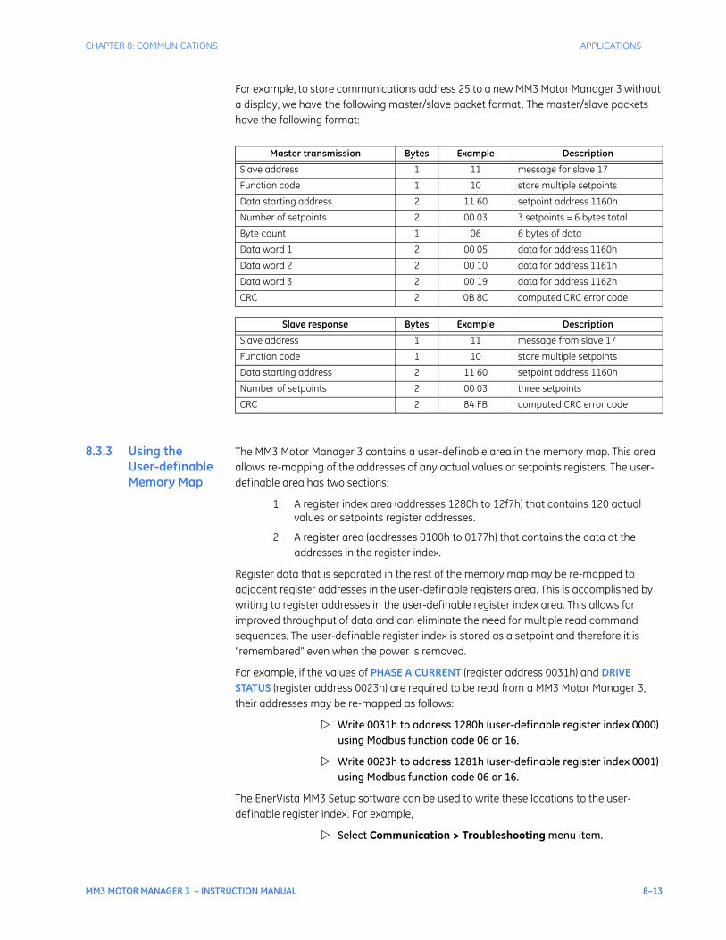
CHAPTER 8: COMMUNICATIONS APPLICATIONS
MM3 MOTOR MANAGER 3 – INSTRUCTION MANUAL 8–13
For example, to store communications address 25 to a new MM3 Motor Manager 3 without a display, we have the following master/slave packet format. The master/slave packets have the following format:
8.3.3 Using the User-definable Memory Map
The MM3 Motor Manager 3 contains a user-definable area in the memory map. This area allows re-mapping of the addresses of any actual values or setpoints registers. The user-definable area has two sections:
1. A register index area (addresses 1280h to 12f7h) that contains 120 actual values or setpoints register addresses.
2. A register area (addresses 0100h to 0177h) that contains the data at the addresses in the register index.
Register data that is separated in the rest of the memory map may be re-mapped to adjacent register addresses in the user-definable registers area. This is accomplished by writing to register addresses in the user-definable register index area. This allows for improved throughput of data and can eliminate the need for multiple read command sequences. The user-definable register index is stored as a setpoint and therefore it is “remembered” even when the power is removed.
For example, if the values of PHASE A CURRENT (register address 0031h) and DRIVE STATUS (register address 0023h) are required to be read from a MM3 Motor Manager 3, their addresses may be re-mapped as follows:
Write 0031h to address 1280h (user-definable register index 0000) using Modbus function code 06 or 16.
Write 0023h to address 1281h (user-definable register index 0001) using Modbus function code 06 or 16.
The EnerVista MM3 Setup software can be used to write these locations to the user-definable register index. For example,
Select Communication > Troubleshooting menu item.
Master transmission Bytes Example Description
Slave address 1 11 message for slave 17
Function code 1 10 store multiple setpoints
Data starting address 2 11 60 setpoint address 1160h
Number of setpoints 2 00 03 3 setpoints = 6 bytes total
Byte count 1 06 6 bytes of data
Data word 1 2 00 05 data for address 1160h
Data word 2 2 00 10 data for address 1161h
Data word 3 2 00 19 data for address 1162h
CRC 2 0B 8C computed CRC error code
Slave response Bytes Example Description
Slave address 1 11 message from slave 17
Function code 1 10 store multiple setpoints
Data starting address 2 11 60 setpoint address 1160h
Number of setpoints 2 00 03 three setpoints
CRC 2 84 FB computed CRC error code
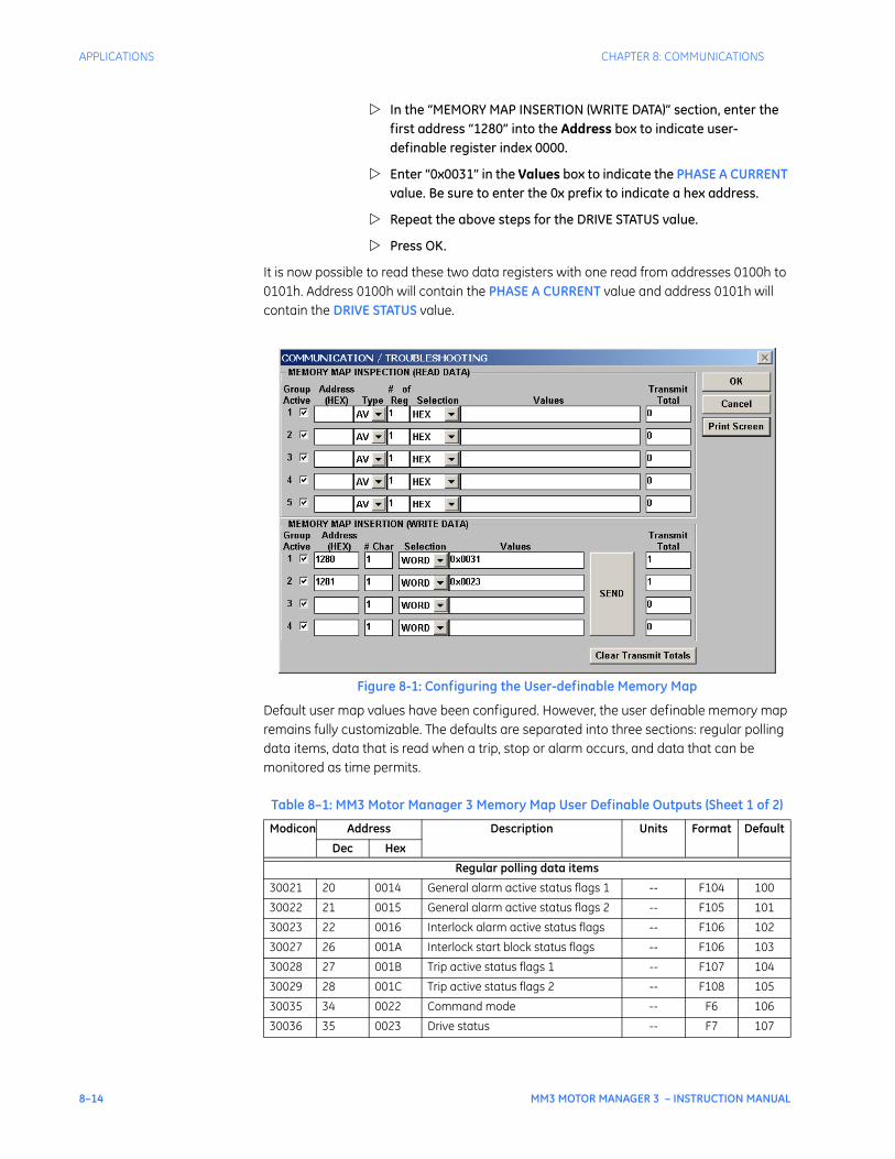
8–14 MM3 MOTOR MANAGER 3 – INSTRUCTION MANUAL
APPLICATIONS CHAPTER 8: COMMUNICATIONS
In the “MEMORY MAP INSERTION (WRITE DATA)” section, enter the first address “1280” into the Address box to indicate user-definable register index 0000.
Enter “0x0031” in the Values box to indicate the PHASE A CURRENT value. Be sure to enter the 0x prefix to indicate a hex address.
Repeat the above steps for the DRIVE STATUS value.
Press OK.
It is now possible to read these two data registers with one read from addresses 0100h to 0101h. Address 0100h will contain the PHASE A CURRENT value and address 0101h will contain the DRIVE STATUS value.
Figure 8-1: Configuring the User-definable Memory Map
Default user map values have been configured. However, the user definable memory map remains fully customizable. The defaults are separated into three sections: regular polling data items, data that is read when a trip, stop or alarm occurs, and data that can be monitored as time permits.
Table 8–1: MM3 Motor Manager 3 Memory Map User Definable Outputs (Sheet 1 of 2)
Modicon Address Description Units Format Default
Dec Hex
Regular polling data items
30021 20 0014 General alarm active status flags 1 -- F104 100
30022 21 0015 General alarm active status flags 2 -- F105 101
30023 22 0016 Interlock alarm active status flags -- F106 102
30027 26 001A Interlock start block status flags -- F106 103
30028 27 001B Trip active status flags 1 -- F107 104
30029 28 001C Trip active status flags 2 -- F108 105
30035 34 0022 Command mode -- F6 106
30036 35 0023 Drive status -- F7 107
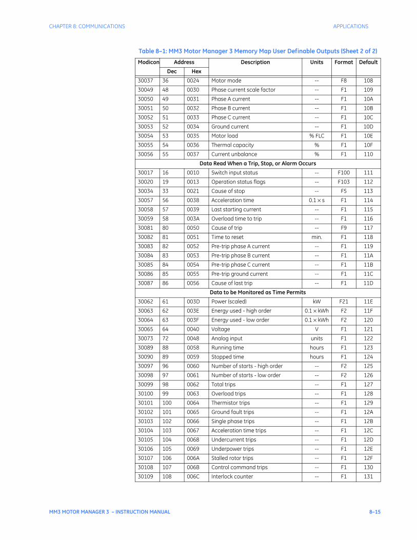
CHAPTER 8: COMMUNICATIONS APPLICATIONS
MM3 MOTOR MANAGER 3 – INSTRUCTION MANUAL 8–15
30037 36 0024 Motor mode -- F8 108
30049 48 0030 Phase current scale factor -- F1 109
30050 49 0031 Phase A current -- F1 10A
30051 50 0032 Phase B current -- F1 10B
30052 51 0033 Phase C current -- F1 10C
30053 52 0034 Ground current -- F1 10D
30054 53 0035 Motor load % FLC F1 10E
30055 54 0036 Thermal capacity % F1 10F
30056 55 0037 Current unbalance % F1 110
Data Read When a Trip, Stop, or Alarm Occurs
30017 16 0010 Switch input status -- F100 111
30020 19 0013 Operation status flags -- F103 112
30034 33 0021 Cause of stop -- F5 113
30057 56 0038 Acceleration time 0.1 × s F1 114
30058 57 0039 Last starting current -- F1 115
30059 58 003A Overload time to trip -- F1 116
30081 80 0050 Cause of trip -- F9 117
30082 81 0051 Time to reset min. F1 118
30083 82 0052 Pre-trip phase A current -- F1 119
30084 83 0053 Pre-trip phase B current -- F1 11A
30085 84 0054 Pre-trip phase C current -- F1 11B
30086 85 0055 Pre-trip ground current -- F1 11C
30087 86 0056 Cause of last trip -- F1 11D
Data to be Monitored as Time Permits
30062 61 003D Power (scaled) kW F21 11E
30063 62 003E Energy used - high order 0.1 × kWh F2 11F
30064 63 003F Energy used - low order 0.1 × kWh F2 120
30065 64 0040 Voltage V F1 121
30073 72 0048 Analog input units F1 122
30089 88 0058 Running time hours F1 123
30090 89 0059 Stopped time hours F1 124
30097 96 0060 Number of starts - high order -- F2 125
30098 97 0061 Number of starts - low order -- F2 126
30099 98 0062 Total trips -- F1 127
30100 99 0063 Overload trips -- F1 128
30101 100 0064 Thermistor trips -- F1 129
30102 101 0065 Ground fault trips -- F1 12A
30103 102 0066 Single phase trips -- F1 12B
30104 103 0067 Acceleration time trips -- F1 12C
30105 104 0068 Undercurrent trips -- F1 12D
30106 105 0069 Underpower trips -- F1 12E
30107 106 006A Stalled rotor trips -- F1 12F
30108 107 006B Control command trips -- F1 130
30109 108 006C Interlock counter -- F1 131
Table 8–1: MM3 Motor Manager 3 Memory Map User Definable Outputs (Sheet 2 of 2)
Modicon Address Description Units Format Default
Dec Hex
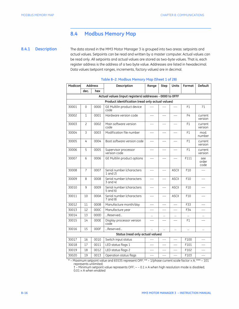
8–16 MM3 MOTOR MANAGER 3 – INSTRUCTION MANUAL
MODBUS MEMORY MAP CHAPTER 8: COMMUNICATIONS
8.4 Modbus Memory Map
8.4.1 Description The data stored in the MM3 Motor Manager 3 is grouped into two areas: setpoints and actual values. Setpoints can be read and written by a master computer. Actual values can be read only. All setpoints and actual values are stored as two-byte values. That is, each register address is the address of a two byte value. Addresses are listed in hexadecimal. Data values (setpoint ranges, increments, factory values) are in decimal.
Table 8–2: Modbus Memory Map (Sheet 1 of 28)
Modicon Address Description Range Step Units Format Default
dec. hex
Actual values (input registers) addresses - 0000 to 0FFF
Product identification (read only actual values)
30001 0 0000 GE Multilin product device code
--- --- --- F1 71
30002 1 0001 Hardware version code --- --- --- F4 current version
30003 2 0002 Main software version code
--- --- --- F1 current version
30004 3 0003 Modification file number --- --- --- F1 mod. number
30005 4 0004 Boot software version code --- --- --- F1 current version
30006 5 0005 Supervisor processor version code
--- --- --- F1 current version
30007 6 0006 GE Multilin product options --- --- --- F111 see order code
30008 7 0007 Serial number (characters 1 and 2)
--- --- ASCII F10 ---
30009 8 0008 Serial number (characters 3 and 4)
--- --- ASCII F10 ---
30010 9 0009 Serial number (characters 5 and 6)
--- --- ASCII F10 ---
30011 10 000A Serial number (characters 7 and 8)
--- --- ASCII F10 ---
30012 11 000B Manufacture month/day --- --- --- F33 ---
30013 12 000C Manufacture year --- --- --- F34 ---
30014 13 000D ...Reserved... ... ... ... ... ...
30015 14 000E Display processor version code
--- --- --- F1 ---
30016 15 000F ...Reserved... ... ... ... ... ...
Status (read only actual values)
30017 16 0010 Switch input status --- --- --- F100 ---
30018 17 0011 LED status flags 1 --- --- --- F101 ---
30019 18 0012 LED status flags 2 --- --- --- F102 ---
30020 19 0013 Operation status flags --- --- --- F103 ---
* – Maximum setpoint value and 65535 represent OFF; ** – 1/phase current scale factor × A; *** – 101 represents unlimited;† – Minimum setpoint value represents OFF; ~ – 0.1 × A when high resolution mode is disabled; 0.01 × A when enabled
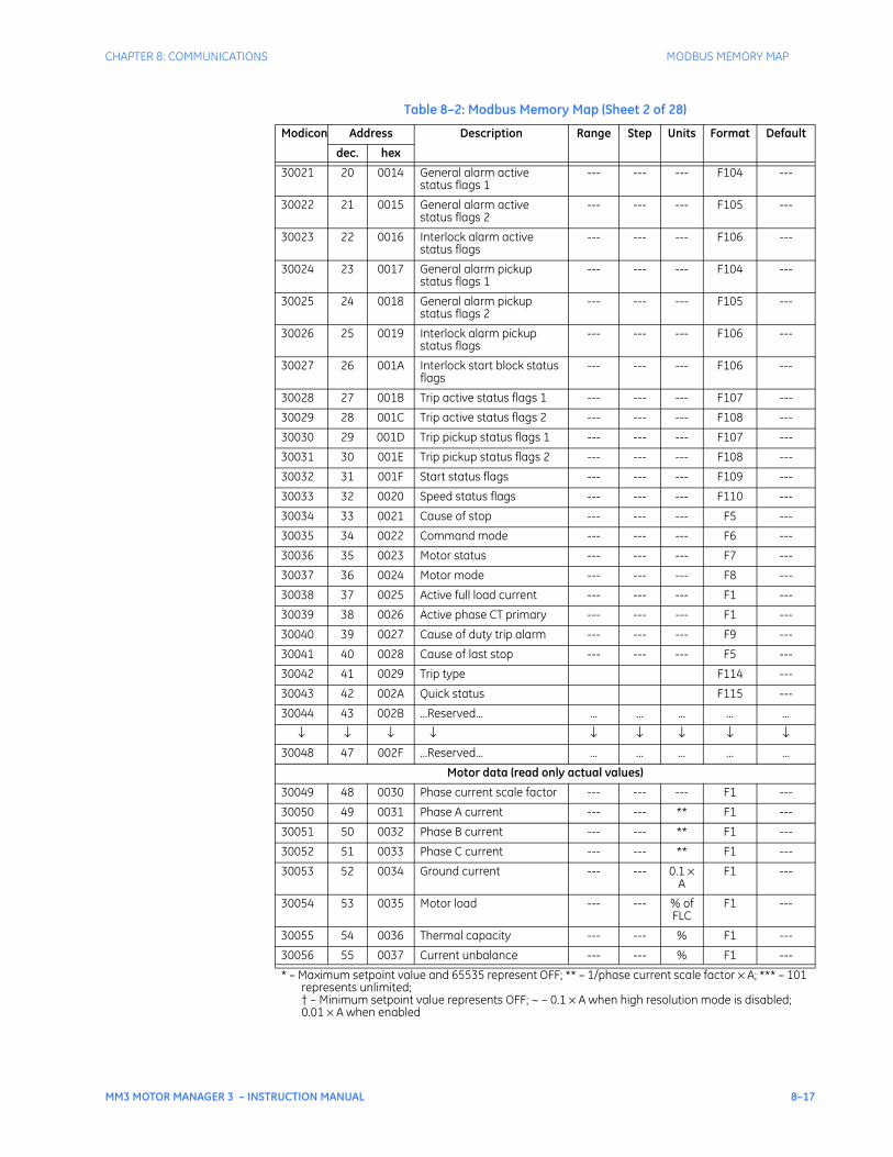
CHAPTER 8: COMMUNICATIONS MODBUS MEMORY MAP
MM3 MOTOR MANAGER 3 – INSTRUCTION MANUAL 8–17
30021 20 0014 General alarm active status flags 1
--- --- --- F104 ---
30022 21 0015 General alarm active status flags 2
--- --- --- F105 ---
30023 22 0016 Interlock alarm active status flags
--- --- --- F106 ---
30024 23 0017 General alarm pickup status flags 1
--- --- --- F104 ---
30025 24 0018 General alarm pickup status flags 2
--- --- --- F105 ---
30026 25 0019 Interlock alarm pickup status flags
--- --- --- F106 ---
30027 26 001A Interlock start block status flags
--- --- --- F106 ---
30028 27 001B Trip active status flags 1 --- --- --- F107 ---
30029 28 001C Trip active status flags 2 --- --- --- F108 ---
30030 29 001D Trip pickup status flags 1 --- --- --- F107 ---
30031 30 001E Trip pickup status flags 2 --- --- --- F108 ---
30032 31 001F Start status flags --- --- --- F109 ---
30033 32 0020 Speed status flags --- --- --- F110 ---
30034 33 0021 Cause of stop --- --- --- F5 ---
30035 34 0022 Command mode --- --- --- F6 ---
30036 35 0023 Motor status --- --- --- F7 ---
30037 36 0024 Motor mode --- --- --- F8 ---
30038 37 0025 Active full load current --- --- --- F1 ---
30039 38 0026 Active phase CT primary --- --- --- F1 ---
30040 39 0027 Cause of duty trip alarm --- --- --- F9 ---
30041 40 0028 Cause of last stop --- --- --- F5 ---
30042 41 0029 Trip type F114 ---
30043 42 002A Quick status F115 ---
30044 43 002B ...Reserved... ... ... ... ... ...
↓ ↓ ↓ ↓ ↓ ↓ ↓ ↓ ↓30048 47 002F ...Reserved... ... ... ... ... ...
Motor data (read only actual values)
30049 48 0030 Phase current scale factor --- --- --- F1 ---
30050 49 0031 Phase A current --- --- ** F1 ---
30051 50 0032 Phase B current --- --- ** F1 ---
30052 51 0033 Phase C current --- --- ** F1 ---
30053 52 0034 Ground current --- --- 0.1 × A
F1 ---
30054 53 0035 Motor load --- --- % of FLC
F1 ---
30055 54 0036 Thermal capacity --- --- % F1 ---
30056 55 0037 Current unbalance --- --- % F1 ---
Table 8–2: Modbus Memory Map (Sheet 2 of 28)
Modicon Address Description Range Step Units Format Default
dec. hex
* – Maximum setpoint value and 65535 represent OFF; ** – 1/phase current scale factor × A; *** – 101 represents unlimited;† – Minimum setpoint value represents OFF; ~ – 0.1 × A when high resolution mode is disabled; 0.01 × A when enabled
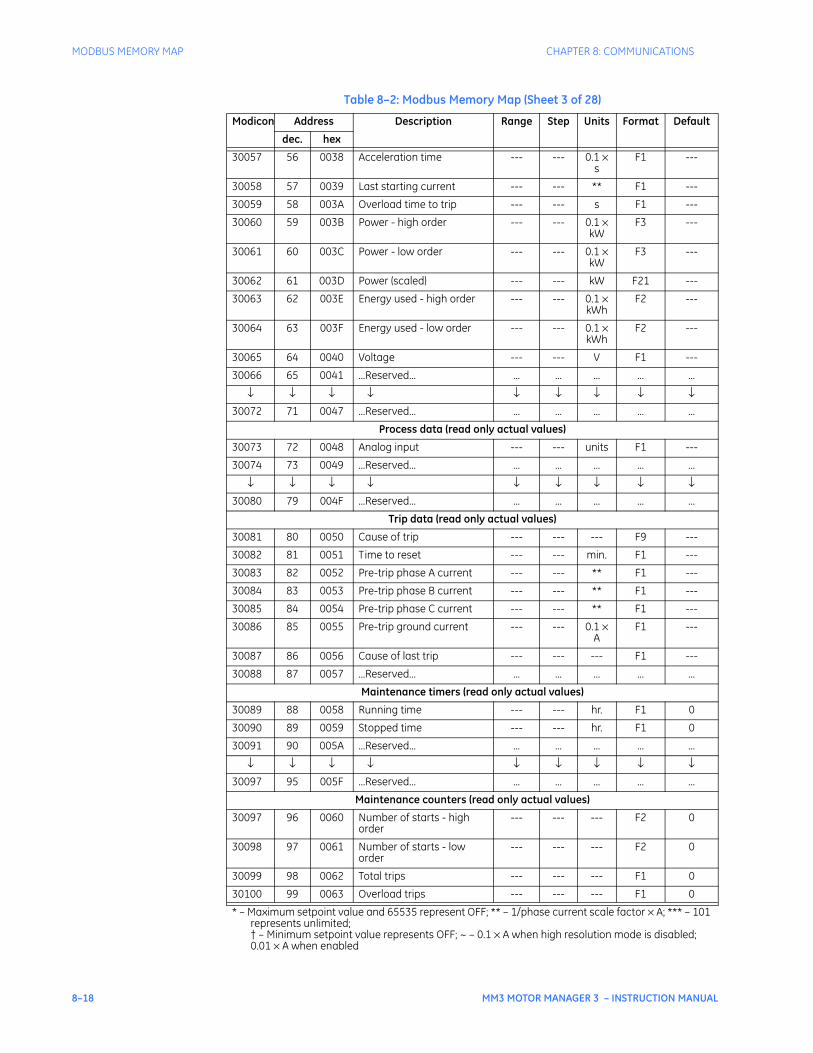
8–18 MM3 MOTOR MANAGER 3 – INSTRUCTION MANUAL
MODBUS MEMORY MAP CHAPTER 8: COMMUNICATIONS
30057 56 0038 Acceleration time --- --- 0.1 × s
F1 ---
30058 57 0039 Last starting current --- --- ** F1 ---
30059 58 003A Overload time to trip --- --- s F1 ---
30060 59 003B Power - high order --- --- 0.1 × kW
F3 ---
30061 60 003C Power - low order --- --- 0.1 × kW
F3 ---
30062 61 003D Power (scaled) --- --- kW F21 ---
30063 62 003E Energy used - high order --- --- 0.1 × kWh
F2 ---
30064 63 003F Energy used - low order --- --- 0.1 × kWh
F2 ---
30065 64 0040 Voltage --- --- V F1 ---
30066 65 0041 ...Reserved... ... ... ... ... ...
↓ ↓ ↓ ↓ ↓ ↓ ↓ ↓ ↓30072 71 0047 ...Reserved... ... ... ... ... ...
Process data (read only actual values)
30073 72 0048 Analog input --- --- units F1 ---
30074 73 0049 ...Reserved... ... ... ... ... ...
↓ ↓ ↓ ↓ ↓ ↓ ↓ ↓ ↓30080 79 004F ...Reserved... ... ... ... ... ...
Trip data (read only actual values)
30081 80 0050 Cause of trip --- --- --- F9 ---
30082 81 0051 Time to reset --- --- min. F1 ---
30083 82 0052 Pre-trip phase A current --- --- ** F1 ---
30084 83 0053 Pre-trip phase B current --- --- ** F1 ---
30085 84 0054 Pre-trip phase C current --- --- ** F1 ---
30086 85 0055 Pre-trip ground current --- --- 0.1 × A
F1 ---
30087 86 0056 Cause of last trip --- --- --- F1 ---
30088 87 0057 ...Reserved... ... ... ... ... ...
Maintenance timers (read only actual values)
30089 88 0058 Running time --- --- hr. F1 0
30090 89 0059 Stopped time --- --- hr. F1 0
30091 90 005A ...Reserved... ... ... ... ... ...
↓ ↓ ↓ ↓ ↓ ↓ ↓ ↓ ↓30097 95 005F ...Reserved... ... ... ... ... ...
Maintenance counters (read only actual values)
30097 96 0060 Number of starts - high order
--- --- --- F2 0
30098 97 0061 Number of starts - low order
--- --- --- F2 0
30099 98 0062 Total trips --- --- --- F1 0
30100 99 0063 Overload trips --- --- --- F1 0
Table 8–2: Modbus Memory Map (Sheet 3 of 28)
Modicon Address Description Range Step Units Format Default
dec. hex
* – Maximum setpoint value and 65535 represent OFF; ** – 1/phase current scale factor × A; *** – 101 represents unlimited;† – Minimum setpoint value represents OFF; ~ – 0.1 × A when high resolution mode is disabled; 0.01 × A when enabled
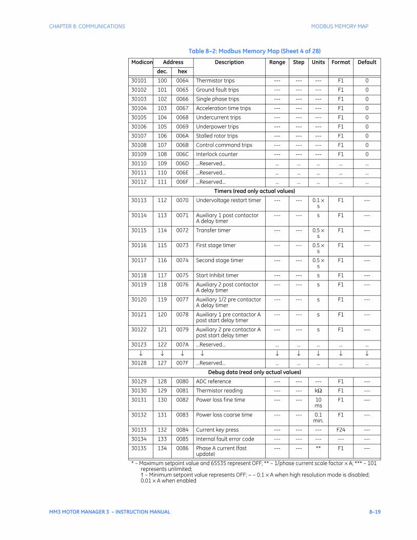
CHAPTER 8: COMMUNICATIONS MODBUS MEMORY MAP
MM3 MOTOR MANAGER 3 – INSTRUCTION MANUAL 8–19
30101 100 0064 Thermistor trips --- --- --- F1 0
30102 101 0065 Ground fault trips --- --- --- F1 0
30103 102 0066 Single phase trips --- --- --- F1 0
30104 103 0067 Acceleration time trips --- --- --- F1 0
30105 104 0068 Undercurrent trips --- --- --- F1 0
30106 105 0069 Underpower trips --- --- --- F1 0
30107 106 006A Stalled rotor trips --- --- --- F1 0
30108 107 006B Control command trips --- --- --- F1 0
30109 108 006C Interlock counter --- --- --- F1 0
30110 109 006D ...Reserved... ... ... ... ... ...
30111 110 006E ...Reserved... ... ... ... ... ...
30112 111 006F ...Reserved... ... ... ... ... ...
Timers (read only actual values)
30113 112 0070 Undervoltage restart timer --- --- 0.1 × s
F1 ---
30114 113 0071 Auxiliary 1 post contactor A delay timer
--- --- s F1 ---
30115 114 0072 Transfer timer --- --- 0.5 × s
F1 ---
30116 115 0073 First stage timer --- --- 0.5 × s
F1 ---
30117 116 0074 Second stage timer --- --- 0.5 × s
F1 ---
30118 117 0075 Start Inhibit timer --- --- s F1 ---
30119 118 0076 Auxiliary 2 post contactor A delay timer
--- --- s F1 ---
30120 119 0077 Auxiliary 1/2 pre contactor A delay timer
--- --- s F1 ---
30121 120 0078 Auxiliary 1 pre contactor A post start delay timer
--- --- s F1 ---
30122 121 0079 Auxiliary 2 pre contactor A post start delay timer
--- --- s F1 ---
30123 122 007A ...Reserved... ... ... ... ... ...
↓ ↓ ↓ ↓ ↓ ↓ ↓ ↓ ↓30128 127 007F ...Reserved... ... ... ... ... ...
Debug data (read only actual values)
30129 128 0080 ADC reference --- --- --- F1 ---
30130 129 0081 Thermistor reading --- --- kΩ F1 ---
30131 130 0082 Power loss fine time --- --- 10 ms
F1 ---
30132 131 0083 Power loss coarse time --- --- 0.1 min.
F1 ---
30133 132 0084 Current key press --- --- --- F24 ---
30134 133 0085 Internal fault error code --- --- --- --- ---
30135 134 0086 Phase A current (fast update)
--- --- ** F1 ---
Table 8–2: Modbus Memory Map (Sheet 4 of 28)
Modicon Address Description Range Step Units Format Default
dec. hex
* – Maximum setpoint value and 65535 represent OFF; ** – 1/phase current scale factor × A; *** – 101 represents unlimited;† – Minimum setpoint value represents OFF; ~ – 0.1 × A when high resolution mode is disabled; 0.01 × A when enabled
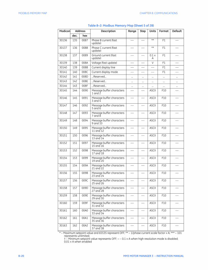
8–20 MM3 MOTOR MANAGER 3 – INSTRUCTION MANUAL
MODBUS MEMORY MAP CHAPTER 8: COMMUNICATIONS
30136 135 0087 Phase B current (fast update)
--- --- ** F1 ---
30137 136 0088 Phase C current (fast update)
--- --- ** F1 ---
30138 137 0089 Ground current (fast update)
--- --- 0.1 × A
F1 ---
30139 138 008A Voltage (fast update) --- --- V F1 ---
30140 139 008B Current display line --- --- --- F1 ---
30141 140 008C Current display mode --- --- --- F1 ---
30142 141 008D ...Reserved... ... ... ... ... ...
30143 142 008E ...Reserved... ... ... ... ... ...
30144 143 008F ...Reserved... ... ... ... ... ...
30145 144 0090 Message buffer characters 1 and 2
--- --- ASCII F10 ---
30146 145 0091 Message buffer characters 3 and 4
--- --- ASCII F10 ---
30147 146 0092 Message buffer characters 5 and 6
--- --- ASCII F10 ---
30148 147 0093 Message buffer characters 7 and 8
--- --- ASCII F10 ---
30149 148 0094 Message buffer characters 9 and 10
--- --- ASCII F10 ---
30150 149 0095 Message buffer characters 11 and 12
--- --- ASCII F10 ---
30151 150 0096 Message buffer characters 13 and 14
--- --- ASCII F10 ---
30152 151 0097 Message buffer characters 15 and 16
--- --- ASCII F10 ---
30153 152 0098 Message buffer characters 17 and 18
--- --- ASCII F10 ---
30154 153 0099 Message buffer characters 19 and 20
--- --- ASCII F10 ---
30155 154 009A Message buffer characters 21 and 22
--- --- ASCII F10 ---
30156 155 009B Message buffer characters 23 and 24
--- --- ASCII F10 ---
30157 156 009C Message buffer characters 25 and 26
--- --- ASCII F10 ---
30158 157 009D Message buffer characters 27 and 28
--- --- ASCII F10 ---
30159 158 009E Message buffer characters 29 and 30
--- --- ASCII F10 ---
30160 159 009F Message buffer characters 31 and 32
--- --- ASCII F10 ---
30161 160 00A0 Message buffer characters 33 and 34
--- --- ASCII F10 ---
30162 161 00A1 Message buffer characters 35 and 36
--- --- ASCII F10 ---
30163 162 00A2 Message buffer characters 37 and 38
--- --- ASCII F10 ---
Table 8–2: Modbus Memory Map (Sheet 5 of 28)
Modicon Address Description Range Step Units Format Default
dec. hex
* – Maximum setpoint value and 65535 represent OFF; ** – 1/phase current scale factor × A; *** – 101 represents unlimited;† – Minimum setpoint value represents OFF; ~ – 0.1 × A when high resolution mode is disabled; 0.01 × A when enabled
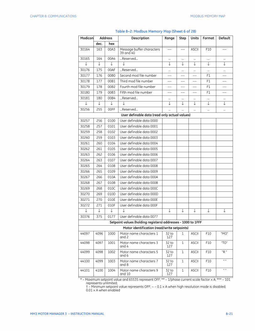
CHAPTER 8: COMMUNICATIONS MODBUS MEMORY MAP
MM3 MOTOR MANAGER 3 – INSTRUCTION MANUAL 8–21
30164 163 00A3 Message buffer characters 39 and 40
--- --- ASCII F10 ---
30165 164 00A4 ...Reserved... ... ... ... ... ...
↓ ↓ ↓ ↓ ↓ ↓ ↓ ↓ ↓30176 175 00AF ...Reserved... ... ... ... ... ...
30177 176 00B0 Second mod file number --- --- --- F1 ---
30178 177 00B1 Third mod file number --- --- --- F1 ---
30179 178 00B2 Fourth mod file number --- --- --- F1 ---
30180 179 00B3 Fifth mod file number --- --- --- F1 ---
30181 180 00B4 ...Reserved... ... ... ... ... ...
↓ ↓ ↓ ↓ ↓ ↓ ↓ ↓ ↓30256 255 00FF ...Reserved... ... ... ... ... ...
User definable data (read only actual values)
30257 256 0100 User definable data 0000
30258 257 0101 User definable data 0001
30259 258 0102 User definable data 0002
30260 259 0103 User definable data 0003
30261 260 0104 User definable data 0004
30262 261 0105 User definable data 0005
30263 262 0106 User definable data 0006
30264 263 0107 User definable data 0007
30265 264 0108 User definable data 0008
30266 265 0109 User definable data 0009
30267 266 010A User definable data 000A
30268 267 010B User definable data 000B
30269 268 010C User definable data 000C
30270 269 010D User definable data 000D
30271 270 010E User definable data 000E
30272 271 010F User definable data 000F
↓ ↓ ↓ ↓ ↓ ↓ ↓ ↓ ↓30376 375 0177 User definable data 0077
Setpoint values (holding registers) addresses - 1000 to 1FFF
Motor identification (read/write setpoints)
44097 4096 1000 Motor name characters 1 and 2
32 to 127
1 ASCII F10 "MO"
44098 4097 1001 Motor name characters 3 and 4
32 to 127
1 ASCII F10 "TO"
44099 4098 1002 Motor name characters 5 and 6
32 to 127
1 ASCII F10 "R "
44100 4099 1003 Motor name characters 7 and 8
32 to 127
1 ASCII F10 " "
44101 4100 1004 Motor name characters 9 and 10
32 to 127
1 ASCII F10 " "
Table 8–2: Modbus Memory Map (Sheet 6 of 28)
Modicon Address Description Range Step Units Format Default
dec. hex
* – Maximum setpoint value and 65535 represent OFF; ** – 1/phase current scale factor × A; *** – 101 represents unlimited;† – Minimum setpoint value represents OFF; ~ – 0.1 × A when high resolution mode is disabled; 0.01 × A when enabled
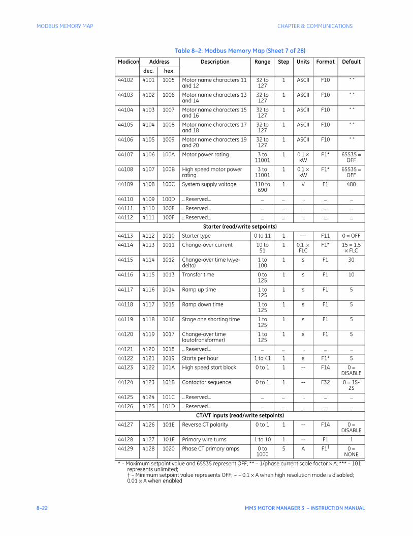
8–22 MM3 MOTOR MANAGER 3 – INSTRUCTION MANUAL
MODBUS MEMORY MAP CHAPTER 8: COMMUNICATIONS
44102 4101 1005 Motor name characters 11 and 12
32 to 127
1 ASCII F10 " "
44103 4102 1006 Motor name characters 13 and 14
32 to 127
1 ASCII F10 " "
44104 4103 1007 Motor name characters 15 and 16
32 to 127
1 ASCII F10 " "
44105 4104 1008 Motor name characters 17 and 18
32 to 127
1 ASCII F10 " "
44106 4105 1009 Motor name characters 19 and 20
32 to 127
1 ASCII F10 " "
44107 4106 100A Motor power rating 3 to 11001
1 0.1 × kW
F1* 65535 = OFF
44108 4107 100B High speed motor power rating
3 to 11001
1 0.1 × kW
F1* 65535 = OFF
44109 4108 100C System supply voltage 110 to 690
1 V F1 480
44110 4109 100D ...Reserved... ... ... ... ... ...
44111 4110 100E ...Reserved... ... ... ... ... ...
44112 4111 100F ...Reserved... ... ... ... ... ...
Starter (read/write setpoints)
44113 4112 1010 Starter type 0 to 11 1 --- F11 0 = OFF
44114 4113 1011 Change-over current 10 to 51
1 0.1 × FLC
F1* 15 = 1.5 × FLC
44115 4114 1012 Change-over time (wye-delta)
1 to 100
1 s F1 30
44116 4115 1013 Transfer time 0 to 125
1 s F1 10
44117 4116 1014 Ramp up time 1 to 125
1 s F1 5
44118 4117 1015 Ramp down time 1 to 125
1 s F1 5
44119 4118 1016 Stage one shorting time 1 to 125
1 s F1 5
44120 4119 1017 Change-over time (autotransformer)
1 to 125
1 s F1 5
44121 4120 1018 ...Reserved... ... ... ... ... ...
44122 4121 1019 Starts per hour 1 to 41 1 s F1* 5
44123 4122 101A High speed start block 0 to 1 1 -- F14 0 = DISABLE
44124 4123 101B Contactor sequence 0 to 1 1 -- F32 0 = 1S-2S
44125 4124 101C ...Reserved... ... ... ... ... ...
44126 4125 101D ...Reserved... ... ... ... ... ...
CT/VT inputs (read/write setpoints)
44127 4126 101E Reverse CT polarity 0 to 1 1 -- F14 0 = DISABLE
44128 4127 101F Primary wire turns 1 to 10 1 -- F1 1
44129 4128 1020 Phase CT primary amps 0 to 1000
5 A F1† 0 = NONE
Table 8–2: Modbus Memory Map (Sheet 7 of 28)
Modicon Address Description Range Step Units Format Default
dec. hex
* – Maximum setpoint value and 65535 represent OFF; ** – 1/phase current scale factor × A; *** – 101 represents unlimited;† – Minimum setpoint value represents OFF; ~ – 0.1 × A when high resolution mode is disabled; 0.01 × A when enabled
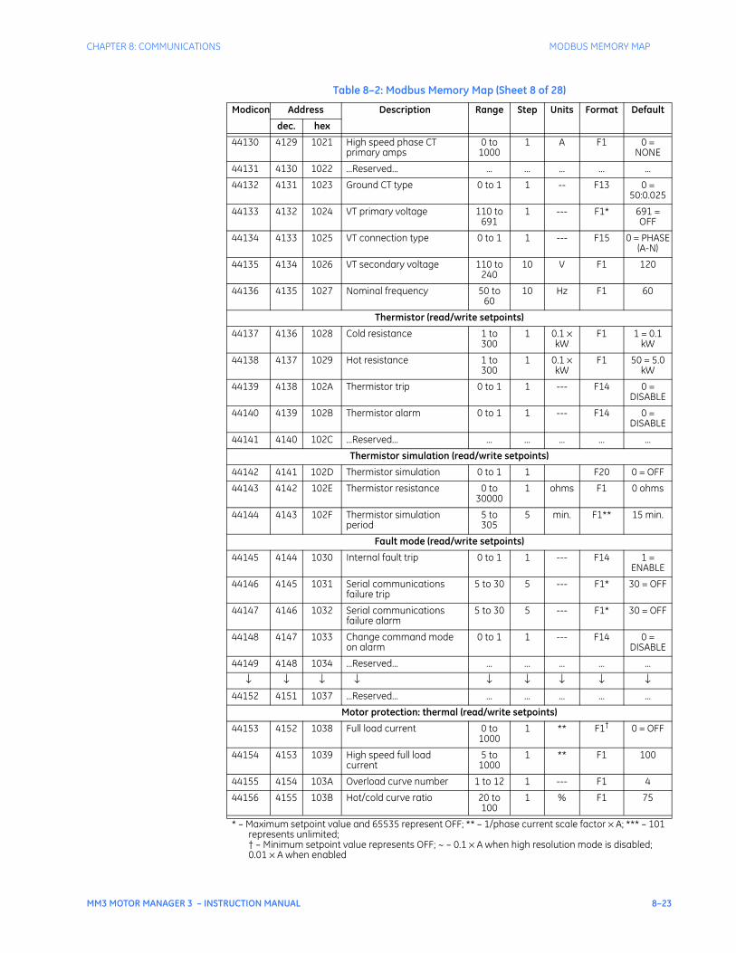
CHAPTER 8: COMMUNICATIONS MODBUS MEMORY MAP
MM3 MOTOR MANAGER 3 – INSTRUCTION MANUAL 8–23
44130 4129 1021 High speed phase CT primary amps
0 to 1000
1 A F1 0 = NONE
44131 4130 1022 ...Reserved... ... ... ... ... ...
44132 4131 1023 Ground CT type 0 to 1 1 -- F13 0 = 50:0.025
44133 4132 1024 VT primary voltage 110 to 691
1 --- F1* 691 = OFF
44134 4133 1025 VT connection type 0 to 1 1 --- F15 0 = PHASE (A-N)
44135 4134 1026 VT secondary voltage 110 to 240
10 V F1 120
44136 4135 1027 Nominal frequency 50 to 60
10 Hz F1 60
Thermistor (read/write setpoints)
44137 4136 1028 Cold resistance 1 to 300
1 0.1 × kW
F1 1 = 0.1 kW
44138 4137 1029 Hot resistance 1 to 300
1 0.1 × kW
F1 50 = 5.0 kW
44139 4138 102A Thermistor trip 0 to 1 1 --- F14 0 = DISABLE
44140 4139 102B Thermistor alarm 0 to 1 1 --- F14 0 = DISABLE
44141 4140 102C ...Reserved... ... ... ... ... ...
Thermistor simulation (read/write setpoints)
44142 4141 102D Thermistor simulation 0 to 1 1 F20 0 = OFF
44143 4142 102E Thermistor resistance 0 to 30000
1 ohms F1 0 ohms
44144 4143 102F Thermistor simulation period
5 to 305
5 min. F1** 15 min.
Fault mode (read/write setpoints)
44145 4144 1030 Internal fault trip 0 to 1 1 --- F14 1 = ENABLE
44146 4145 1031 Serial communications failure trip
5 to 30 5 --- F1* 30 = OFF
44147 4146 1032 Serial communications failure alarm
5 to 30 5 --- F1* 30 = OFF
44148 4147 1033 Change command mode on alarm
0 to 1 1 --- F14 0 = DISABLE
44149 4148 1034 ...Reserved... ... ... ... ... ...
↓ ↓ ↓ ↓ ↓ ↓ ↓ ↓ ↓44152 4151 1037 ...Reserved... ... ... ... ... ...
Motor protection: thermal (read/write setpoints)
44153 4152 1038 Full load current 0 to 1000
1 ** F1† 0 = OFF
44154 4153 1039 High speed full load current
5 to 1000
1 ** F1 100
44155 4154 103A Overload curve number 1 to 12 1 --- F1 4
44156 4155 103B Hot/cold curve ratio 20 to 100
1 % F1 75
Table 8–2: Modbus Memory Map (Sheet 8 of 28)
Modicon Address Description Range Step Units Format Default
dec. hex
* – Maximum setpoint value and 65535 represent OFF; ** – 1/phase current scale factor × A; *** – 101 represents unlimited;† – Minimum setpoint value represents OFF; ~ – 0.1 × A when high resolution mode is disabled; 0.01 × A when enabled
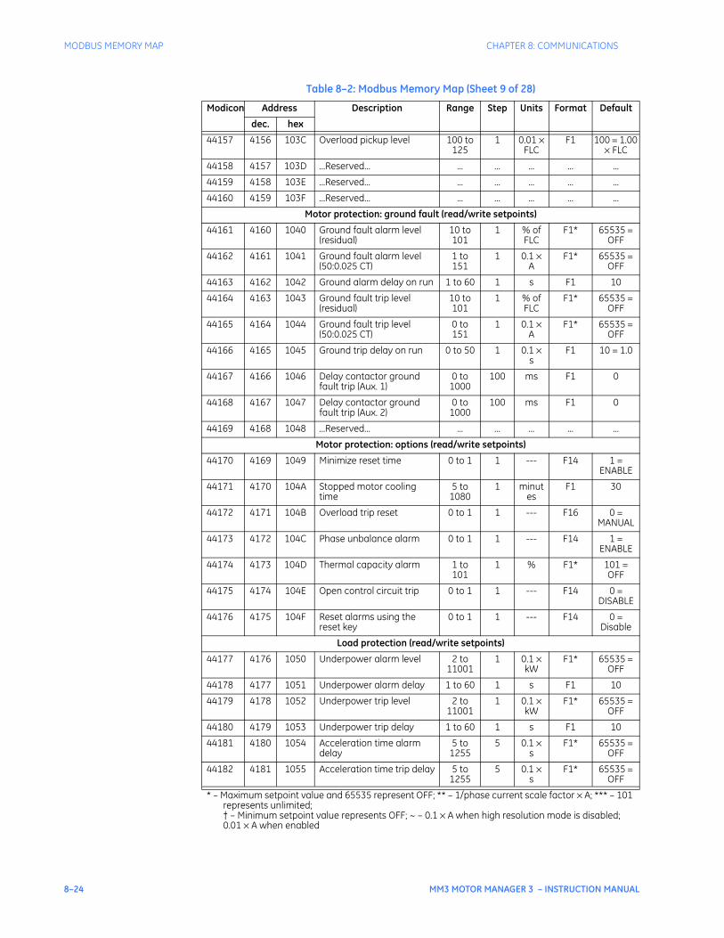
8–24 MM3 MOTOR MANAGER 3 – INSTRUCTION MANUAL
MODBUS MEMORY MAP CHAPTER 8: COMMUNICATIONS
44157 4156 103C Overload pickup level 100 to 125
1 0.01 × FLC
F1 100 = 1.00 × FLC
44158 4157 103D ...Reserved... ... ... ... ... ...
44159 4158 103E ...Reserved... ... ... ... ... ...
44160 4159 103F ...Reserved... ... ... ... ... ...
Motor protection: ground fault (read/write setpoints)
44161 4160 1040 Ground fault alarm level (residual)
10 to 101
1 % of FLC
F1* 65535 = OFF
44162 4161 1041 Ground fault alarm level (50:0.025 CT)
1 to 151
1 0.1 × A
F1* 65535 = OFF
44163 4162 1042 Ground alarm delay on run 1 to 60 1 s F1 10
44164 4163 1043 Ground fault trip level (residual)
10 to 101
1 % of FLC
F1* 65535 = OFF
44165 4164 1044 Ground fault trip level (50:0.025 CT)
0 to 151
1 0.1 × A
F1* 65535 = OFF
44166 4165 1045 Ground trip delay on run 0 to 50 1 0.1 × s
F1 10 = 1.0
44167 4166 1046 Delay contactor ground fault trip (Aux. 1)
0 to 1000
100 ms F1 0
44168 4167 1047 Delay contactor ground fault trip (Aux. 2)
0 to 1000
100 ms F1 0
44169 4168 1048 ...Reserved... ... ... ... ... ...
Motor protection: options (read/write setpoints)
44170 4169 1049 Minimize reset time 0 to 1 1 --- F14 1 = ENABLE
44171 4170 104A Stopped motor cooling time
5 to 1080
1 minutes
F1 30
44172 4171 104B Overload trip reset 0 to 1 1 --- F16 0 = MANUAL
44173 4172 104C Phase unbalance alarm 0 to 1 1 --- F14 1 = ENABLE
44174 4173 104D Thermal capacity alarm 1 to 101
1 % F1* 101 = OFF
44175 4174 104E Open control circuit trip 0 to 1 1 --- F14 0 = DISABLE
44176 4175 104F Reset alarms using the reset key
0 to 1 1 --- F14 0 = Disable
Load protection (read/write setpoints)
44177 4176 1050 Underpower alarm level 2 to 11001
1 0.1 × kW
F1* 65535 = OFF
44178 4177 1051 Underpower alarm delay 1 to 60 1 s F1 10
44179 4178 1052 Underpower trip level 2 to 11001
1 0.1 × kW
F1* 65535 = OFF
44180 4179 1053 Underpower trip delay 1 to 60 1 s F1 10
44181 4180 1054 Acceleration time alarm delay
5 to 1255
5 0.1 × s
F1* 65535 = OFF
44182 4181 1055 Acceleration time trip delay 5 to 1255
5 0.1 × s
F1* 65535 = OFF
Table 8–2: Modbus Memory Map (Sheet 9 of 28)
Modicon Address Description Range Step Units Format Default
dec. hex
* – Maximum setpoint value and 65535 represent OFF; ** – 1/phase current scale factor × A; *** – 101 represents unlimited;† – Minimum setpoint value represents OFF; ~ – 0.1 × A when high resolution mode is disabled; 0.01 × A when enabled
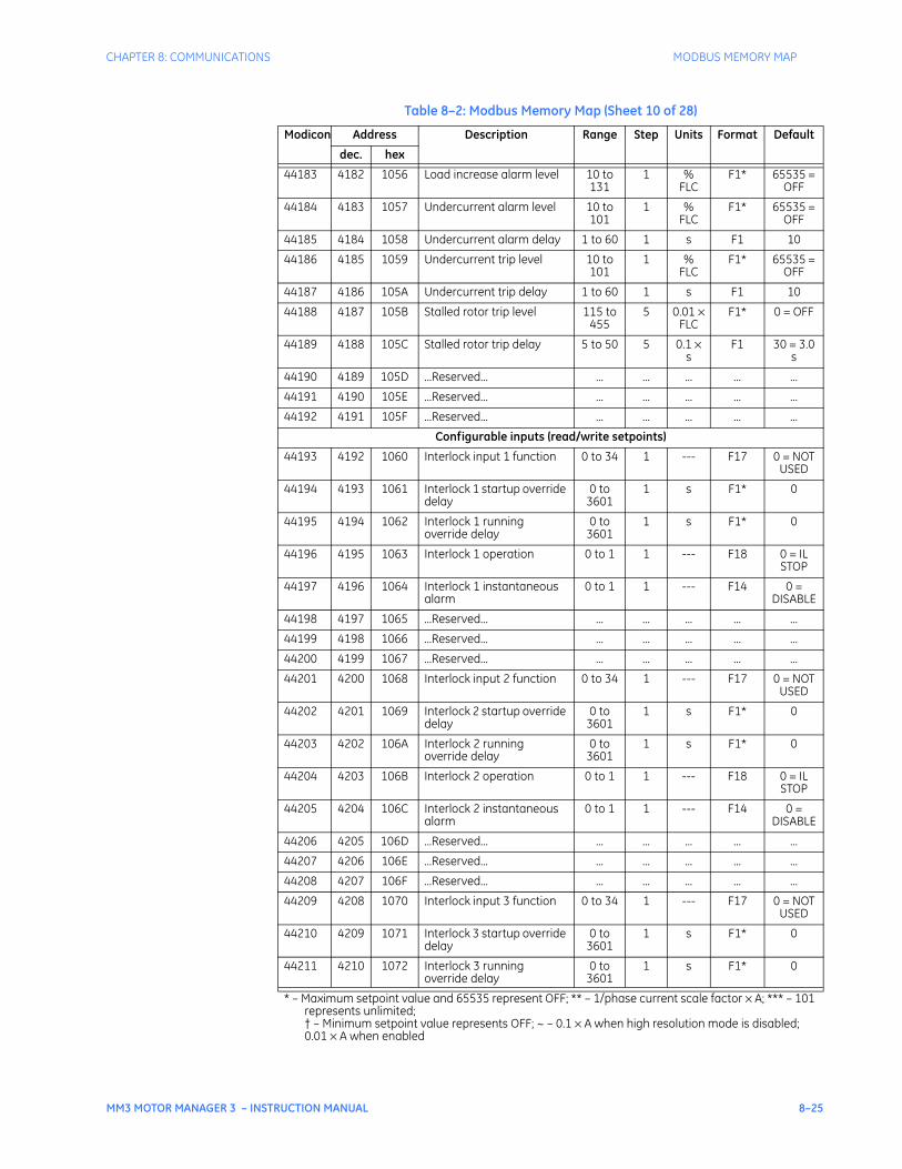
CHAPTER 8: COMMUNICATIONS MODBUS MEMORY MAP
MM3 MOTOR MANAGER 3 – INSTRUCTION MANUAL 8–25
44183 4182 1056 Load increase alarm level 10 to 131
1 % FLC
F1* 65535 = OFF
44184 4183 1057 Undercurrent alarm level 10 to 101
1 % FLC
F1* 65535 = OFF
44185 4184 1058 Undercurrent alarm delay 1 to 60 1 s F1 10
44186 4185 1059 Undercurrent trip level 10 to 101
1 % FLC
F1* 65535 = OFF
44187 4186 105A Undercurrent trip delay 1 to 60 1 s F1 10
44188 4187 105B Stalled rotor trip level 115 to 455
5 0.01 × FLC
F1* 0 = OFF
44189 4188 105C Stalled rotor trip delay 5 to 50 5 0.1 × s
F1 30 = 3.0 s
44190 4189 105D ...Reserved... ... ... ... ... ...
44191 4190 105E ...Reserved... ... ... ... ... ...
44192 4191 105F ...Reserved... ... ... ... ... ...
Configurable inputs (read/write setpoints)
44193 4192 1060 Interlock input 1 function 0 to 34 1 --- F17 0 = NOT USED
44194 4193 1061 Interlock 1 startup override delay
0 to 3601
1 s F1* 0
44195 4194 1062 Interlock 1 running override delay
0 to 3601
1 s F1* 0
44196 4195 1063 Interlock 1 operation 0 to 1 1 --- F18 0 = IL STOP
44197 4196 1064 Interlock 1 instantaneous alarm
0 to 1 1 --- F14 0 = DISABLE
44198 4197 1065 ...Reserved... ... ... ... ... ...
44199 4198 1066 ...Reserved... ... ... ... ... ...
44200 4199 1067 ...Reserved... ... ... ... ... ...
44201 4200 1068 Interlock input 2 function 0 to 34 1 --- F17 0 = NOT USED
44202 4201 1069 Interlock 2 startup override delay
0 to 3601
1 s F1* 0
44203 4202 106A Interlock 2 running override delay
0 to 3601
1 s F1* 0
44204 4203 106B Interlock 2 operation 0 to 1 1 --- F18 0 = IL STOP
44205 4204 106C Interlock 2 instantaneous alarm
0 to 1 1 --- F14 0 = DISABLE
44206 4205 106D ...Reserved... ... ... ... ... ...
44207 4206 106E ...Reserved... ... ... ... ... ...
44208 4207 106F ...Reserved... ... ... ... ... ...
44209 4208 1070 Interlock input 3 function 0 to 34 1 --- F17 0 = NOT USED
44210 4209 1071 Interlock 3 startup override delay
0 to 3601
1 s F1* 0
44211 4210 1072 Interlock 3 running override delay
0 to 3601
1 s F1* 0
Table 8–2: Modbus Memory Map (Sheet 10 of 28)
Modicon Address Description Range Step Units Format Default
dec. hex
* – Maximum setpoint value and 65535 represent OFF; ** – 1/phase current scale factor × A; *** – 101 represents unlimited;† – Minimum setpoint value represents OFF; ~ – 0.1 × A when high resolution mode is disabled; 0.01 × A when enabled
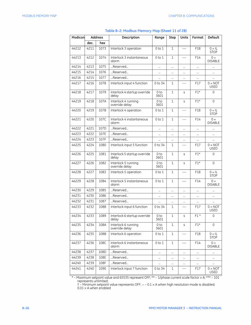
8–26 MM3 MOTOR MANAGER 3 – INSTRUCTION MANUAL
MODBUS MEMORY MAP CHAPTER 8: COMMUNICATIONS
44212 4211 1073 Interlock 3 operation 0 to 1 1 --- F18 0 = IL STOP
44213 4212 1074 Interlock 3 instantaneous alarm
0 to 1 1 --- F14 0 = DISABLE
44214 4213 1075 ...Reserved... ... ... ... ... ...
44215 4214 1076 ...Reserved... ... ... ... ... ...
44216 4215 1077 ...Reserved... ... ... ... ... ...
44217 4216 1078 Interlock input 4 function 0 to 34 1 --- F17 0 = NOT USED
44218 4217 1079 Interlock 4 startup override delay
0 to 3601
1 s F1* 0
44219 4218 107A Interlock 4 running override delay
0 to 3601
1 s F1* 0
44220 4219 107B Interlock 4 operation 0 to 1 1 --- F18 0 = IL STOP
44221 4220 107C Interlock 4 instantaneous alarm
0 to 1 1 --- F14 0 = DISABLE
44222 4221 107D ...Reserved... ... ... ... ... ...
44223 4222 107E ...Reserved... ... ... ... ... ...
44224 4223 107F ...Reserved... ... ... ... ... ...
44225 4224 1080 Interlock input 5 function 0 to 34 1 --- F17 0 = NOT USED
44226 4225 1081 Interlock 5 startup override delay
0 to 3601
1 s F1* 0
44227 4226 1082 Interlock 5 running override delay
0 to 3601
1 s F1* 0
44228 4227 1083 Interlock 5 operation 0 to 1 1 --- F18 0 = IL STOP
44229 4228 1084 Interlock 5 instantaneous alarm
0 to 1 1 --- F14 0 = DISABLE
44230 4229 1085 ...Reserved... ... ... ... ... ...
44231 4230 1086 ...Reserved... ... ... ... ... ...
44232 4231 1087 ...Reserved... ... ... ... ... ...
44233 4232 1088 Interlock input 6 function 0 to 34 1 --- F17 0 = NOT USED
44234 4233 1089 Interlock 6 startup override delay
0 to 3601
1 s F1 * 0
44235 4234 108A Interlock 6 running override delay
0 to 3601
1 s F1* 0
44236 4235 108B Interlock 6 operation 0 to 1 1 --- F18 0 = IL STOP
44237 4236 108C Interlock 6 instantaneous alarm
0 to 1 1 --- F14 0 = DISABLE
44238 4237 108D ...Reserved... ... ... ... ... ...
44239 4238 108E ...Reserved... ... ... ... ... ...
44240 4239 108F ...Reserved... ... ... ... ... ...
44241 4240 1090 Interlock input 7 function 0 to 34 1 --- F17 0 = NOT USED
Table 8–2: Modbus Memory Map (Sheet 11 of 28)
Modicon Address Description Range Step Units Format Default
dec. hex
* – Maximum setpoint value and 65535 represent OFF; ** – 1/phase current scale factor × A; *** – 101 represents unlimited;† – Minimum setpoint value represents OFF; ~ – 0.1 × A when high resolution mode is disabled; 0.01 × A when enabled
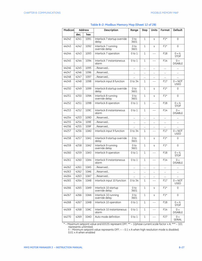
CHAPTER 8: COMMUNICATIONS MODBUS MEMORY MAP
MM3 MOTOR MANAGER 3 – INSTRUCTION MANUAL 8–27
44242 4241 1091 Interlock 7 startup override delay
0 to 3601
1 s F1* 0
44243 4242 1092 Interlock 7 running override delay
0 to 3601
1 s F1* 0
44244 4243 1093 Interlock 7 operation 0 to 1 1 --- F18 0 = IL STOP
44245 4244 1094 Interlock 7 instantaneous alarm
0 to 1 1 --- F14 0 = DISABLE
44246 4245 1095 ...Reserved... ... ... ... ... ...
44247 4246 1096 ...Reserved... ... ... ... ... ...
44248 4247 1097 ...Reserved... ... ... ... ... ...
44249 4248 1098 Interlock input 8 function 0 to 34 1 --- F17 0 = NOT USED
44250 4249 1099 Interlock 8 startup override delay
0 to 3601
1 s F1* 0
44251 4250 109A Interlock 8 running override delay
0 to 3601
1 s F1* 0
44252 4251 109B Interlock 8 operation 0 to 1 1 --- F18 0 = IL STOP
44253 4252 109C Interlock 8 instantaneous alarm
0 to 1 1 --- F14 0 = DISABLE
44254 4253 109D ...Reserved... ... ... ... ... ...
44255 4254 109E ...Reserved... ... ... ... ... ...
44256 4255 109F ...Reserved... ... ... ... ... ...
44257 4256 10A0 Interlock input 9 function 0 to 34 1 --- F17 0 = NOT USED
44258 4257 10A1 Interlock 9 startup override delay
0 to 3601
1 s F1* 0
44259 4258 10A2 Interlock 9 running override delay
0 to 3601
1 s F1* 0
44260 4259 10A3 Interlock 9 operation 0 to 1 1 --- F18 0 = IL STOP
44261 4260 10A4 Interlock 9 instantaneous alarm
0 to 1 1 --- F14 0 = DISABLE
44262 4261 10A5 ...Reserved... ... ... ... ... ...
44263 4262 10A6 ...Reserved... ... ... ... ... ...
44264 4263 10A7 ...Reserved... ... ... ... ... ...
44265 4264 10A8 Interlock input 10 function 0 to 34 1 --- F17 0 = NOT USED
44266 4265 10A9 Interlock 10 startup override delay
0 to 3601
1 s F1* 0
44267 4266 10AA Interlock 10 running override delay
0 to 3601
1 s F1* 0
44268 4267 10AB Interlock 10 operation 0 to 1 1 --- F18 0 = IL STOP
44269 4268 10AC Interlock 10 instantaneous alarm
0 to 1 1 --- F14 0 = DISABLE
44270 4269 10AD Auto mode definition 0 to 1 1 --- F27 0 = SERIAL
Table 8–2: Modbus Memory Map (Sheet 12 of 28)
Modicon Address Description Range Step Units Format Default
dec. hex
* – Maximum setpoint value and 65535 represent OFF; ** – 1/phase current scale factor × A; *** – 101 represents unlimited;† – Minimum setpoint value represents OFF; ~ – 0.1 × A when high resolution mode is disabled; 0.01 × A when enabled
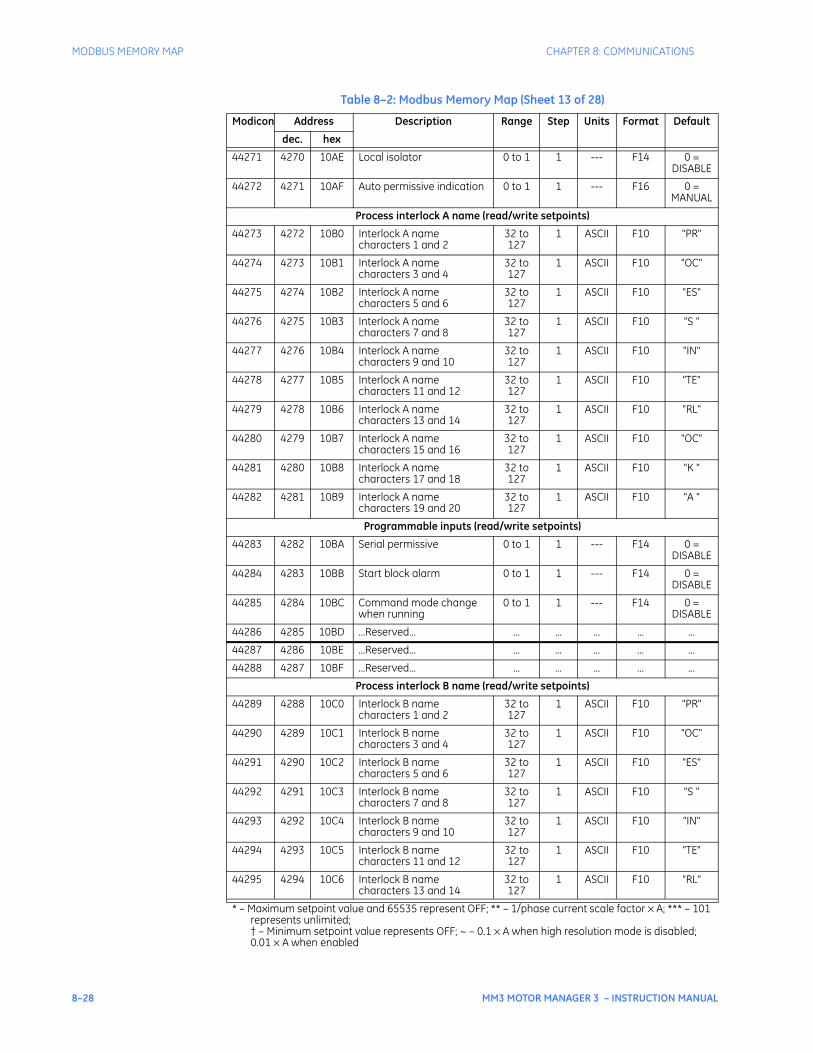
8–28 MM3 MOTOR MANAGER 3 – INSTRUCTION MANUAL
MODBUS MEMORY MAP CHAPTER 8: COMMUNICATIONS
44271 4270 10AE Local isolator 0 to 1 1 --- F14 0 = DISABLE
44272 4271 10AF Auto permissive indication 0 to 1 1 --- F16 0 = MANUAL
Process interlock A name (read/write setpoints)
44273 4272 10B0 Interlock A name characters 1 and 2
32 to 127
1 ASCII F10 "PR"
44274 4273 10B1 Interlock A name characters 3 and 4
32 to 127
1 ASCII F10 "OC"
44275 4274 10B2 Interlock A name characters 5 and 6
32 to 127
1 ASCII F10 "ES"
44276 4275 10B3 Interlock A name characters 7 and 8
32 to 127
1 ASCII F10 "S "
44277 4276 10B4 Interlock A name characters 9 and 10
32 to 127
1 ASCII F10 "IN"
44278 4277 10B5 Interlock A name characters 11 and 12
32 to 127
1 ASCII F10 "TE"
44279 4278 10B6 Interlock A name characters 13 and 14
32 to 127
1 ASCII F10 "RL"
44280 4279 10B7 Interlock A name characters 15 and 16
32 to 127
1 ASCII F10 "OC"
44281 4280 10B8 Interlock A name characters 17 and 18
32 to 127
1 ASCII F10 "K "
44282 4281 10B9 Interlock A name characters 19 and 20
32 to 127
1 ASCII F10 "A "
Programmable inputs (read/write setpoints)
44283 4282 10BA Serial permissive 0 to 1 1 --- F14 0 = DISABLE
44284 4283 10BB Start block alarm 0 to 1 1 --- F14 0 = DISABLE
44285 4284 10BC Command mode change when running
0 to 1 1 --- F14 0 = DISABLE
44286 4285 10BD ...Reserved... ... ... ... ... ...
44287 4286 10BE ...Reserved... ... ... ... ... ...
44288 4287 10BF ...Reserved... ... ... ... ... ...
Process interlock B name (read/write setpoints)
44289 4288 10C0 Interlock B name characters 1 and 2
32 to 127
1 ASCII F10 "PR"
44290 4289 10C1 Interlock B name characters 3 and 4
32 to 127
1 ASCII F10 "OC"
44291 4290 10C2 Interlock B name characters 5 and 6
32 to 127
1 ASCII F10 "ES"
44292 4291 10C3 Interlock B name characters 7 and 8
32 to 127
1 ASCII F10 "S "
44293 4292 10C4 Interlock B name characters 9 and 10
32 to 127
1 ASCII F10 "IN"
44294 4293 10C5 Interlock B name characters 11 and 12
32 to 127
1 ASCII F10 "TE"
44295 4294 10C6 Interlock B name characters 13 and 14
32 to 127
1 ASCII F10 "RL"
Table 8–2: Modbus Memory Map (Sheet 13 of 28)
Modicon Address Description Range Step Units Format Default
dec. hex
* – Maximum setpoint value and 65535 represent OFF; ** – 1/phase current scale factor × A; *** – 101 represents unlimited;† – Minimum setpoint value represents OFF; ~ – 0.1 × A when high resolution mode is disabled; 0.01 × A when enabled
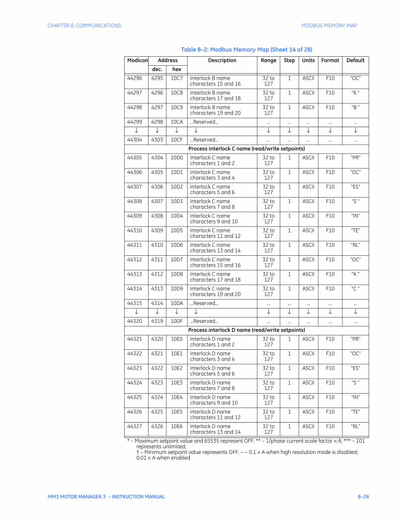
CHAPTER 8: COMMUNICATIONS MODBUS MEMORY MAP
MM3 MOTOR MANAGER 3 – INSTRUCTION MANUAL 8–29
44296 4295 10C7 Interlock B name characters 15 and 16
32 to 127
1 ASCII F10 "OC"
44297 4296 10C8 Interlock B name characters 17 and 18
32 to 127
1 ASCII F10 "K "
44298 4297 10C9 Interlock B name characters 19 and 20
32 to 127
1 ASCII F10 "B "
44299 4298 10CA ...Reserved... ... ... ... ... ...
↓ ↓ ↓ ↓ ↓ ↓ ↓ ↓ ↓44304 4303 10CF ...Reserved... ... ... ... ... ...
Process interlock C name (read/write setpoints)
44305 4304 10D0 Interlock C name characters 1 and 2
32 to 127
1 ASCII F10 "PR"
44306 4305 10D1 Interlock C name characters 3 and 4
32 to 127
1 ASCII F10 "OC"
44307 4306 10D2 Interlock C name characters 5 and 6
32 to 127
1 ASCII F10 "ES"
44308 4307 10D3 Interlock C name characters 7 and 8
32 to 127
1 ASCII F10 "S "
44309 4308 10D4 Interlock C name characters 9 and 10
32 to 127
1 ASCII F10 "IN"
44310 4309 10D5 Interlock C name characters 11 and 12
32 to 127
1 ASCII F10 "TE"
44311 4310 10D6 Interlock C name characters 13 and 14
32 to 127
1 ASCII F10 "RL"
44312 4311 10D7 Interlock C name characters 15 and 16
32 to 127
1 ASCII F10 "OC"
44313 4312 10D8 Interlock C name characters 17 and 18
32 to 127
1 ASCII F10 "K "
44314 4313 10D9 Interlock C name characters 19 and 20
32 to 127
1 ASCII F10 "C "
44315 4314 10DA ...Reserved... ... ... ... ... ...
↓ ↓ ↓ ↓ ↓ ↓ ↓ ↓ ↓44320 4319 10DF ...Reserved... ... ... ... ... ...
Process interlock D name (read/write setpoints)
44321 4320 10E0 Interlock D name characters 1 and 2
32 to 127
1 ASCII F10 "PR"
44322 4321 10E1 Interlock D name characters 3 and 4
32 to 127
1 ASCII F10 "OC"
44323 4322 10E2 Interlock D name characters 5 and 6
32 to 127
1 ASCII F10 "ES"
44324 4323 10E3 Interlock D name characters 7 and 8
32 to 127
1 ASCII F10 "S "
44325 4324 10E4 Interlock D name characters 9 and 10
32 to 127
1 ASCII F10 "IN"
44326 4325 10E5 Interlock D name characters 11 and 12
32 to 127
1 ASCII F10 "TE"
44327 4326 10E6 Interlock D name characters 13 and 14
32 to 127
1 ASCII F10 "RL"
Table 8–2: Modbus Memory Map (Sheet 14 of 28)
Modicon Address Description Range Step Units Format Default
dec. hex
* – Maximum setpoint value and 65535 represent OFF; ** – 1/phase current scale factor × A; *** – 101 represents unlimited;† – Minimum setpoint value represents OFF; ~ – 0.1 × A when high resolution mode is disabled; 0.01 × A when enabled
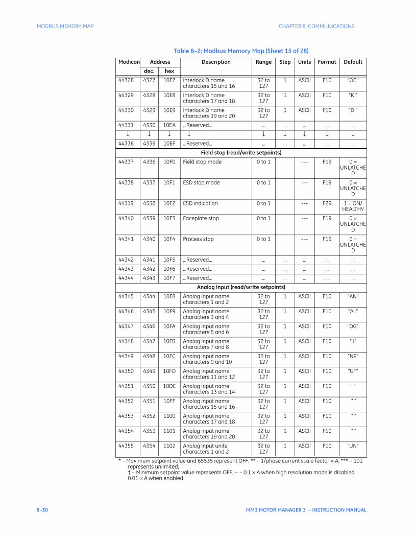
8–30 MM3 MOTOR MANAGER 3 – INSTRUCTION MANUAL
MODBUS MEMORY MAP CHAPTER 8: COMMUNICATIONS
44328 4327 10E7 Interlock D name characters 15 and 16
32 to 127
1 ASCII F10 "OC"
44329 4328 10E8 Interlock D name characters 17 and 18
32 to 127
1 ASCII F10 "K "
44330 4329 10E9 Interlock D name characters 19 and 20
32 to 127
1 ASCII F10 "D "
44331 4330 10EA ...Reserved... ... ... ... ... ...
↓ ↓ ↓ ↓ ↓ ↓ ↓ ↓ ↓44336 4335 10EF ...Reserved... ... ... ... ... ...
Field stop (read/write setpoints)
44337 4336 10F0 Field stop mode 0 to 1 --- F19 0 = UNLATCHE
D
44338 4337 10F1 ESD stop mode 0 to 1 --- F19 0 = UNLATCHE
D
44339 4338 10F2 ESD indication 0 to 1 --- F29 1 = ON/HEALTHY
44340 4339 10F3 Faceplate stop 0 to 1 --- F19 0 = UNLATCHE
D
44341 4340 10F4 Process stop 0 to 1 --- F19 0 = UNLATCHE
D
44342 4341 10F5 ...Reserved... ... ... ... ... ...
44343 4342 10F6 ...Reserved... ... ... ... ... ...
44344 4343 10F7 ...Reserved... ... ... ... ... ...
Analog input (read/write setpoints)
44345 4344 10F8 Analog input name characters 1 and 2
32 to 127
1 ASCII F10 "AN"
44346 4345 10F9 Analog input name characters 3 and 4
32 to 127
1 ASCII F10 "AL"
44347 4346 10FA Analog input name characters 5 and 6
32 to 127
1 ASCII F10 "OG"
44348 4347 10FB Analog input name characters 7 and 8
32 to 127
1 ASCII F10 " I"
44349 4348 10FC Analog input name characters 9 and 10
32 to 127
1 ASCII F10 "NP"
44350 4349 10FD Analog input name characters 11 and 12
32 to 127
1 ASCII F10 "UT"
44351 4350 10DE Analog input name characters 13 and 14
32 to 127
1 ASCII F10 " "
44352 4351 10FF Analog input name characters 15 and 16
32 to 127
1 ASCII F10 " "
44353 4352 1100 Analog input name characters 17 and 18
32 to 127
1 ASCII F10 " "
44354 4353 1101 Analog input name characters 19 and 20
32 to 127
1 ASCII F10 " "
44355 4354 1102 Analog input units characters 1 and 2
32 to 127
1 ASCII F10 "UN"
Table 8–2: Modbus Memory Map (Sheet 15 of 28)
Modicon Address Description Range Step Units Format Default
dec. hex
* – Maximum setpoint value and 65535 represent OFF; ** – 1/phase current scale factor × A; *** – 101 represents unlimited;† – Minimum setpoint value represents OFF; ~ – 0.1 × A when high resolution mode is disabled; 0.01 × A when enabled
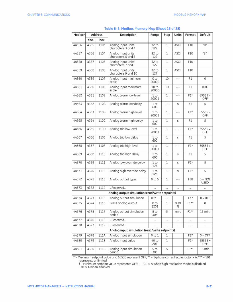
CHAPTER 8: COMMUNICATIONS MODBUS MEMORY MAP
MM3 MOTOR MANAGER 3 – INSTRUCTION MANUAL 8–31
44356 4355 1103 Analog input units characters 3 and 4
32 to 127
1 ASCII F10 "IT"
44357 4356 1104 Analog input units characters 5 and 6
32 to 127
1 ASCII F10 "S "
44358 4357 1105 Analog input units characters 7 and 8
32 to 127
1 ASCII F10
44359 4358 1106 Analog input units characters 9 and 10
32 to 127
1 ASCII F10
44360 4359 1107 Analog input minimum scale
0 to 20000
10 --- F1 0
44361 4360 1108 Analog input maximum scale
10 to 20000
10 --- F1 1000
44362 4361 1109 Analog alarm low level 1 to 20001
1 --- F1* 65535 = OFF
44363 4362 110A Analog alarm low delay 1 to 600
1 s F1 5
44364 4363 110B Analog alarm high level 1 to 20001
1 --- F1* 65535 = OFF
44365 4364 110C Analog alarm high delay 1 to 600
1 s F1 5
44366 4365 110D Analog trip low level 1 to 20001
1 --- F1* 65535 = OFF
44367 4366 110E Analog trip low delay 1 to 600
1 s F1 5
44368 4367 110F Analog trip high level 1 to 20001
1 --- F1* 65535 = OFF
44369 4368 1110 Analog trip high delay 1 to 600
1 s F1 5
44370 4369 1111 Analog low override delay 1 to 126
1 s F1* 5
44371 4370 1112 Analog high override delay 1 to 126
1 s F1* 5
44372 4371 1113 Analog output type 0 to 5 1 --- F38 0 = NOT USED
44373 4372 1114 ...Reserved... ... ... ... ... ...
Analog output simulation (read/write setpoints)
44374 4373 1115 Analog output simulation 0 to 1 1 F37 0 = 0FF
44375 4374 1116 Force analog output 0 to 1201
1 0.10%
F1** 0
44376 4375 1117 Analog output simulation period
5 to 305
5 min. F1** 15 min.
44377 4376 1118 ...Reserved... ... ... ... ... ...
44378 4377 1119 ...Reserved... ... ... ... ... ...
Analog input simulation (read/write setpoints)
44379 4378 111A Analog input simulation 0 to 1 1 F37 0 = OFF
44380 4379 111B Analog input value 40 to 201
1 F1* 65535 = OFF
44381 4380 111C Analog input simulation period
5 to 305
5 F1** 15 min.
Table 8–2: Modbus Memory Map (Sheet 16 of 28)
Modicon Address Description Range Step Units Format Default
dec. hex
* – Maximum setpoint value and 65535 represent OFF; ** – 1/phase current scale factor × A; *** – 101 represents unlimited;† – Minimum setpoint value represents OFF; ~ – 0.1 × A when high resolution mode is disabled; 0.01 × A when enabled
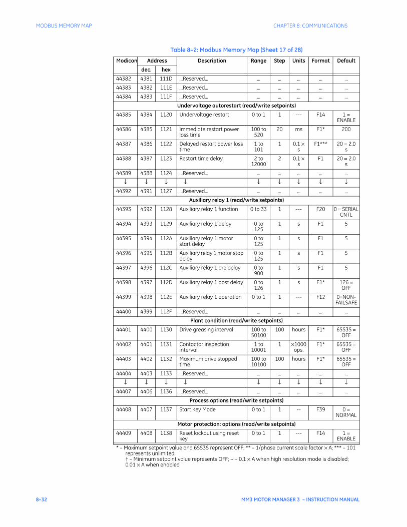
8–32 MM3 MOTOR MANAGER 3 – INSTRUCTION MANUAL
MODBUS MEMORY MAP CHAPTER 8: COMMUNICATIONS
44382 4381 111D ...Reserved... ... ... ... ... ...
44383 4382 111E ...Reserved... ... ... ... ... ...
44384 4383 111F ...Reserved... ... ... ... ... ...
Undervoltage autorestart (read/write setpoints)
44385 4384 1120 Undervoltage restart 0 to 1 1 --- F14 1 = ENABLE
44386 4385 1121 Immediate restart power loss time
100 to 520
20 ms F1* 200
44387 4386 1122 Delayed restart power loss time
1 to 101
1 0.1 × s
F1*** 20 = 2.0 s
44388 4387 1123 Restart time delay 2 to 12000
2 0.1 × s
F1 20 = 2.0 s
44389 4388 1124 ...Reserved... ... ... ... ... ...
↓ ↓ ↓ ↓ ↓ ↓ ↓ ↓ ↓44392 4391 1127 ...Reserved... ... ... ... ... ...
Auxiliary relay 1 (read/write setpoints)
44393 4392 1128 Auxiliary relay 1 function 0 to 33 1 --- F20 0 = SERIAL CNTL
44394 4393 1129 Auxiliary relay 1 delay 0 to 125
1 s F1 5
44395 4394 112A Auxiliary relay 1 motor start delay
0 to 125
1 s F1 5
44396 4395 112B Auxiliary relay 1 motor stop delay
0 to 125
1 s F1 5
44397 4396 112C Auxiliary relay 1 pre delay 0 to 900
1 s F1 5
44398 4397 112D Auxiliary relay 1 post delay 0 to 126
1 s F1* 126 = OFF
44399 4398 112E Auxiliary relay 1 operation 0 to 1 1 --- F12 0=NON-FAILSAFE
44400 4399 112F ...Reserved... ... ... ... ... ...
Plant condition (read/write setpoints)
44401 4400 1130 Drive greasing interval 100 to 50100
100 hours F1* 65535 = OFF
44402 4401 1131 Contactor inspection interval
1 to 10001
1 ×1000 ops.
F1* 65535 = OFF
44403 4402 1132 Maximum drive stopped time
100 to 10100
100 hours F1* 65535 = OFF
44404 4403 1133 ...Reserved... ... ... ... ... ...
↓ ↓ ↓ ↓ ↓ ↓ ↓ ↓ ↓44407 4406 1136 ...Reserved... ... ... ... ... ...
Process options (read/write setpoints)
44408 4407 1137 Start Key Mode 0 to 1 1 -- F39 0 = NORMAL
Motor protection: options (read/write setpoints)
44409 4408 1138 Reset lockout using reset key
0 to 1 1 --- F14 1 = ENABLE
Table 8–2: Modbus Memory Map (Sheet 17 of 28)
Modicon Address Description Range Step Units Format Default
dec. hex
* – Maximum setpoint value and 65535 represent OFF; ** – 1/phase current scale factor × A; *** – 101 represents unlimited;† – Minimum setpoint value represents OFF; ~ – 0.1 × A when high resolution mode is disabled; 0.01 × A when enabled
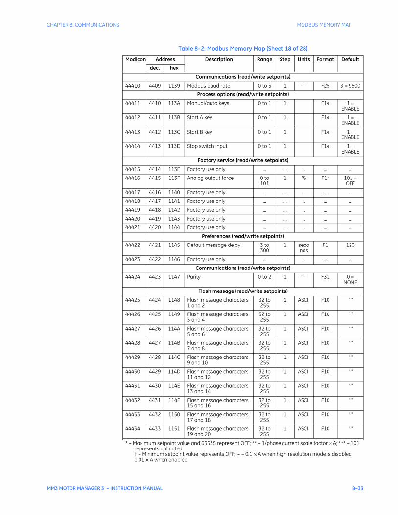
CHAPTER 8: COMMUNICATIONS MODBUS MEMORY MAP
MM3 MOTOR MANAGER 3 – INSTRUCTION MANUAL 8–33
Communications (read/write setpoints)
44410 4409 1139 Modbus baud rate 0 to 5 1 --- F25 3 = 9600
Process options (read/write setpoints)
44411 4410 113A Manual/auto keys 0 to 1 1 F14 1 = ENABLE
44412 4411 113B Start A key 0 to 1 1 F14 1 = ENABLE
44413 4412 113C Start B key 0 to 1 1 F14 1 = ENABLE
44414 4413 113D Stop switch input 0 to 1 1 F14 1 = ENABLE
Factory service (read/write setpoints)
44415 4414 113E Factory use only ... ... ... ... ...
44416 4415 113F Analog output force 0 to 101
1 % F1* 101 = OFF
44417 4416 1140 Factory use only ... ... ... ... ...
44418 4417 1141 Factory use only ... ... ... ... ...
44419 4418 1142 Factory use only ... ... ... ... ...
44420 4419 1143 Factory use only ... ... ... ... ...
44421 4420 1144 Factory use only ... ... ... ... ...
Preferences (read/write setpoints)
44422 4421 1145 Default message delay 3 to 300
1 seconds
F1 120
44423 4422 1146 Factory use only ... ... ... ... ...
Communications (read/write setpoints)
44424 4423 1147 Parity 0 to 2 1 --- F31 0 = NONE
Flash message (read/write setpoints)
44425 4424 1148 Flash message characters 1 and 2
32 to 255
1 ASCII F10 " "
44426 4425 1149 Flash message characters 3 and 4
32 to 255
1 ASCII F10 " "
44427 4426 114A Flash message characters 5 and 6
32 to 255
1 ASCII F10 " "
44428 4427 114B Flash message characters 7 and 8
32 to 255
1 ASCII F10 " "
44429 4428 114C Flash message characters 9 and 10
32 to 255
1 ASCII F10 " "
44430 4429 114D Flash message characters 11 and 12
32 to 255
1 ASCII F10 " "
44431 4430 114E Flash message characters 13 and 14
32 to 255
1 ASCII F10 " "
44432 4431 114F Flash message characters 15 and 16
32 to 255
1 ASCII F10 " "
44433 4432 1150 Flash message characters 17 and 18
32 to 255
1 ASCII F10 " "
44434 4433 1151 Flash message characters 19 and 20
32 to 255
1 ASCII F10 " "
Table 8–2: Modbus Memory Map (Sheet 18 of 28)
Modicon Address Description Range Step Units Format Default
dec. hex
* – Maximum setpoint value and 65535 represent OFF; ** – 1/phase current scale factor × A; *** – 101 represents unlimited;† – Minimum setpoint value represents OFF; ~ – 0.1 × A when high resolution mode is disabled; 0.01 × A when enabled
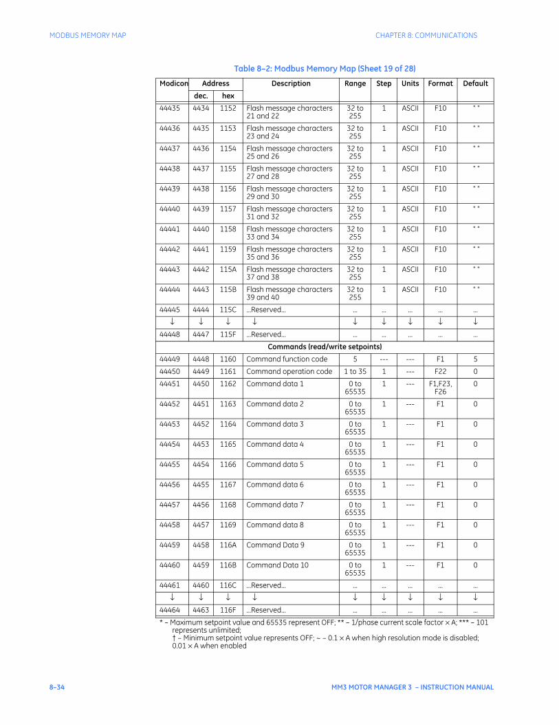
8–34 MM3 MOTOR MANAGER 3 – INSTRUCTION MANUAL
MODBUS MEMORY MAP CHAPTER 8: COMMUNICATIONS
44435 4434 1152 Flash message characters 21 and 22
32 to 255
1 ASCII F10 " "
44436 4435 1153 Flash message characters 23 and 24
32 to 255
1 ASCII F10 " "
44437 4436 1154 Flash message characters 25 and 26
32 to 255
1 ASCII F10 " "
44438 4437 1155 Flash message characters 27 and 28
32 to 255
1 ASCII F10 " "
44439 4438 1156 Flash message characters 29 and 30
32 to 255
1 ASCII F10 " "
44440 4439 1157 Flash message characters 31 and 32
32 to 255
1 ASCII F10 " "
44441 4440 1158 Flash message characters 33 and 34
32 to 255
1 ASCII F10 " "
44442 4441 1159 Flash message characters 35 and 36
32 to 255
1 ASCII F10 " "
44443 4442 115A Flash message characters 37 and 38
32 to 255
1 ASCII F10 " "
44444 4443 115B Flash message characters 39 and 40
32 to 255
1 ASCII F10 " "
44445 4444 115C ...Reserved... ... ... ... ... ...
↓ ↓ ↓ ↓ ↓ ↓ ↓ ↓ ↓44448 4447 115F ...Reserved... ... ... ... ... ...
Commands (read/write setpoints)
44449 4448 1160 Command function code 5 --- --- F1 5
44450 4449 1161 Command operation code 1 to 35 1 --- F22 0
44451 4450 1162 Command data 1 0 to 65535
1 --- F1,F23,F26
0
44452 4451 1163 Command data 2 0 to 65535
1 --- F1 0
44453 4452 1164 Command data 3 0 to 65535
1 --- F1 0
44454 4453 1165 Command data 4 0 to 65535
1 --- F1 0
44455 4454 1166 Command data 5 0 to 65535
1 --- F1 0
44456 4455 1167 Command data 6 0 to 65535
1 --- F1 0
44457 4456 1168 Command data 7 0 to 65535
1 --- F1 0
44458 4457 1169 Command data 8 0 to 65535
1 --- F1 0
44459 4458 116A Command Data 9 0 to 65535
1 --- F1 0
44460 4459 116B Command Data 10 0 to 65535
1 --- F1 0
44461 4460 116C ...Reserved... ... ... ... ... ...
↓ ↓ ↓ ↓ ↓ ↓ ↓ ↓ ↓44464 4463 116F ...Reserved... ... ... ... ... ...
Table 8–2: Modbus Memory Map (Sheet 19 of 28)
Modicon Address Description Range Step Units Format Default
dec. hex
* – Maximum setpoint value and 65535 represent OFF; ** – 1/phase current scale factor × A; *** – 101 represents unlimited;† – Minimum setpoint value represents OFF; ~ – 0.1 × A when high resolution mode is disabled; 0.01 × A when enabled
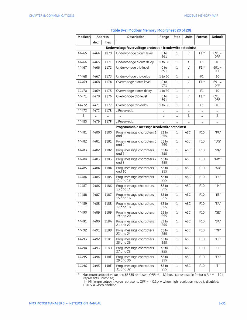
CHAPTER 8: COMMUNICATIONS MODBUS MEMORY MAP
MM3 MOTOR MANAGER 3 – INSTRUCTION MANUAL 8–35
Undervoltage/overvoltage protection (read/write setpoints)
44465 4464 1170 Undervoltage alarm level 0 to 691
1 V F1 * 691 = 0FF
44466 4465 1171 Undervoltage alarm delay 1 to 60 1 s F1 10
44467 4466 1172 Undervoltage trip level 0 to 691
1 V F1 * 691 = 0FF
44468 4467 1173 Undervoltage trip delay 1 to 60 1 s F1 10
44469 4468 1174 Overvoltage alarm level 0 to 691
1 V F1 * 691 = 0FF
44470 4469 1175 Overvoltage alarm delay 1 to 60 1 s F1 10
44471 4470 1176 Overvoltage trip level 0 to 691
1 V F1 * 691 = 0FF
44472 4471 1177 Overvoltage trip delay 1 to 60 1 s F1 10
44473 4472 1178 ...Reserved... ... ... ... ... ...
↓ ↓ ↓ ↓ ↓ ↓ ↓ ↓ ↓44480 4479 117F ...Reserved... ... ... ... ... ...
Programmable message (read/write setpoints)
44481 4480 1180 Prog. message characters 1 and 2
32 to 255
1 ASCII F10 "PR"
44482 4481 1181 Prog. message characters 3 and 4
32 to 255
1 ASCII F10 "OG"
44483 4482 1182 Prog. message characters 5 and 6
32 to 255
1 ASCII F10 "RA"
44484 4483 1183 Prog. message characters 7 and 8
32 to 255
1 ASCII F10 "MM"
44485 4484 1184 Prog. message characters 9 and 10
32 to 255
1 ASCII F10 "AB"
44486 4485 1185 Prog. message characters 11 and 12
32 to 255
1 ASCII F10 "LE"
44487 4486 1186 Prog. message characters 13 and 14
32 to 255
1 ASCII F10 " M"
44488 4487 1187 Prog. message characters 15 and 16
32 to 255
1 ASCII F10 "ES"
44489 4488 1188 Prog. message characters 17 and 18
32 to 255
1 ASCII F10 "SA"
44490 4489 1189 Prog. message characters 19 and 20
32 to 255
1 ASCII F10 "GE"
44491 4490 118A Prog. message characters 21 and 22
32 to 255
1 ASCII F10 "SA"
44492 4491 118B Prog. message characters 23 and 24
32 to 255
1 ASCII F10 "MP"
44493 4492 118C Prog. message characters 25 and 26
32 to 255
1 ASCII F10 "LE"
44494 4493 118D Prog. message characters 27 and 28
32 to 255
1 ASCII F10 " T"
44495 4494 118E Prog. message characters 29 and 30
32 to 255
1 ASCII F10 "EX"
44496 4495 118F Prog. message characters 31 and 32
32 to 255
1 ASCII F10 "T "
Table 8–2: Modbus Memory Map (Sheet 20 of 28)
Modicon Address Description Range Step Units Format Default
dec. hex
* – Maximum setpoint value and 65535 represent OFF; ** – 1/phase current scale factor × A; *** – 101 represents unlimited;† – Minimum setpoint value represents OFF; ~ – 0.1 × A when high resolution mode is disabled; 0.01 × A when enabled
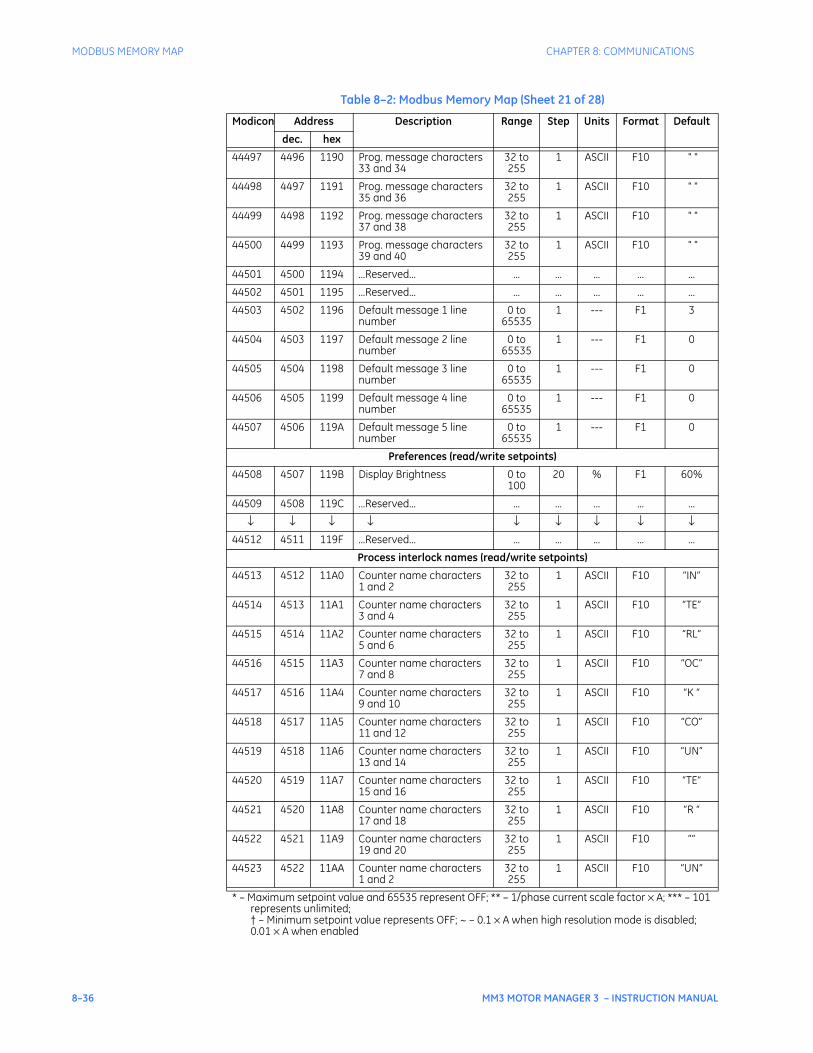
8–36 MM3 MOTOR MANAGER 3 – INSTRUCTION MANUAL
MODBUS MEMORY MAP CHAPTER 8: COMMUNICATIONS
44497 4496 1190 Prog. message characters 33 and 34
32 to 255
1 ASCII F10 " "
44498 4497 1191 Prog. message characters 35 and 36
32 to 255
1 ASCII F10 " "
44499 4498 1192 Prog. message characters 37 and 38
32 to 255
1 ASCII F10 " "
44500 4499 1193 Prog. message characters 39 and 40
32 to 255
1 ASCII F10 " "
44501 4500 1194 ...Reserved... ... ... ... ... ...
44502 4501 1195 ...Reserved... ... ... ... ... ...
44503 4502 1196 Default message 1 line number
0 to 65535
1 --- F1 3
44504 4503 1197 Default message 2 line number
0 to 65535
1 --- F1 0
44505 4504 1198 Default message 3 line number
0 to 65535
1 --- F1 0
44506 4505 1199 Default message 4 line number
0 to 65535
1 --- F1 0
44507 4506 119A Default message 5 line number
0 to 65535
1 --- F1 0
Preferences (read/write setpoints)
44508 4507 119B Display Brightness 0 to 100
20 % F1 60%
44509 4508 119C ...Reserved... ... ... ... ... ...
↓ ↓ ↓ ↓ ↓ ↓ ↓ ↓ ↓44512 4511 119F ...Reserved... ... ... ... ... ...
Process interlock names (read/write setpoints)
44513 4512 11A0 Counter name characters 1 and 2
32 to 255
1 ASCII F10 “IN”
44514 4513 11A1 Counter name characters 3 and 4
32 to 255
1 ASCII F10 “TE”
44515 4514 11A2 Counter name characters 5 and 6
32 to 255
1 ASCII F10 “RL”
44516 4515 11A3 Counter name characters 7 and 8
32 to 255
1 ASCII F10 “OC”
44517 4516 11A4 Counter name characters 9 and 10
32 to 255
1 ASCII F10 “K “
44518 4517 11A5 Counter name characters 11 and 12
32 to 255
1 ASCII F10 “CO”
44519 4518 11A6 Counter name characters 13 and 14
32 to 255
1 ASCII F10 “UN”
44520 4519 11A7 Counter name characters 15 and 16
32 to 255
1 ASCII F10 “TE”
44521 4520 11A8 Counter name characters 17 and 18
32 to 255
1 ASCII F10 “R “
44522 4521 11A9 Counter name characters 19 and 20
32 to 255
1 ASCII F10 ““
44523 4522 11AA Counter name characters 1 and 2
32 to 255
1 ASCII F10 “UN”
Table 8–2: Modbus Memory Map (Sheet 21 of 28)
Modicon Address Description Range Step Units Format Default
dec. hex
* – Maximum setpoint value and 65535 represent OFF; ** – 1/phase current scale factor × A; *** – 101 represents unlimited;† – Minimum setpoint value represents OFF; ~ – 0.1 × A when high resolution mode is disabled; 0.01 × A when enabled
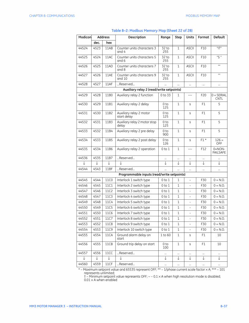
CHAPTER 8: COMMUNICATIONS MODBUS MEMORY MAP
MM3 MOTOR MANAGER 3 – INSTRUCTION MANUAL 8–37
44524 4523 11AB Counter units characters 3 and 4
32 to 255
1 ASCII F10 “IT”
44525 4524 11AC Counter units characters 5 and 6
32 to 255
1 ASCII F10 “S “
44526 4525 11AD Counter units characters 7 and 8
32 to 255
1 ASCII F10 ““
44527 4526 11AE Counter units characters 9 and 10
32 to 255
1 ASCII F10 ““
44528 4527 11AF ...Reserved... ... ... ... ... ...
Auxiliary relay 2 (read/write setpoints)
44529 4528 11B0 Auxiliary relay 2 function 0 to 33 1 --- F20 0 = SERIAL CNTL
44530 4529 11B1 Auxiliary relay 2 delay 0 to 125
1 s F1 5
44531 4530 11B2 Auxiliary relay 2 motor start delay
0 to 125
1 s F1 5
44532 4531 11B3 Auxiliary relay 2 motor stop delay
0 to 125
1 s F1 5
44533 4532 11B4 Auxiliary relay 2 pre delay 0 to 900
1 s F1 5
44534 4533 11B5 Auxiliary relay 2 post delay 0 to 126
1 s F1 * 126 = OFF
44535 4534 11B6 Auxiliary relay 2 operation 0 to 1 1 --- F12 0=NON-FAILSAFE
44536 4535 11B7 ...Reserved... ... ... ... ... ...
↓ ↓ ↓ ↓ ↓ ↓ ↓ ↓ ↓44544 4543 11BF ...Reserved... ... ... ... ... ...
Programmable inputs (read/write setpoints)
44545 4544 11C0 Interlock 1 switch type 0 to 1 1 - F30 0 = N.O.
44546 4545 11C1 Interlock 2 switch type 0 to 1 1 - F30 0 = N.O.
44547 4546 11C2 Interlock 3 switch type 0 to 1 1 - F30 0 = N.O.
44548 4547 11C3 Interlock 4 switch type 0 to 1 1 - F30 0 = N.O.
44549 4548 11C4 Interlock 5 switch type 0 to 1 1 - F30 0 = N.O.
44550 4549 11C5 Interlock 6 switch type 0 to 1 1 - F30 0 = N.O.
44551 4550 11C6 Interlock 7 switch type 0 to 1 1 - F30 0 = N.O.
44552 4551 11C7 Interlock 8 switch type 0 to 1 1 - F30 0 = N.O.
44553 4552 11C8 Interlock 9 switch type 0 to 1 1 - F30 0 = N.O.
44554 4553 11C9 Interlock 10 switch type 0 to 1 1 - F30 0 = N.O.
44555 4554 11CA Ground alarm delay on start
1 to 60 1 s F1 10
44556 4555 11CB Ground trip delay on start 0 to 100
1 s F1 10
44557 4556 11CC ...Reserved... ... ... ... ... ...
↓ ↓ ↓ ↓ ↓ ↓ ↓ ↓ ↓44560 4559 11CF ...Reserved... ... ... ... ... ...
Table 8–2: Modbus Memory Map (Sheet 22 of 28)
Modicon Address Description Range Step Units Format Default
dec. hex
* – Maximum setpoint value and 65535 represent OFF; ** – 1/phase current scale factor × A; *** – 101 represents unlimited;† – Minimum setpoint value represents OFF; ~ – 0.1 × A when high resolution mode is disabled; 0.01 × A when enabled

8–38 MM3 MOTOR MANAGER 3 – INSTRUCTION MANUAL
MODBUS MEMORY MAP CHAPTER 8: COMMUNICATIONS
Process interlock E name (read/write setpoints)
44561 4560 11D0 Interlock E name characters 1 and 2
32 to 127
1 ASCII F10 ‘PR’
44562 4561 11D1 Interlock E name characters 3 and 4
32 to 127
1 ASCII F10 ‘OC’
44563 4562 11D2 Interlock E name characters 5 and 6
32 to 127
1 ASCII F10 ‘ES’
44564 4563 11D3 Interlock E name characters 7 and 8
32 to 127
1 ASCII F10 ‘S ‘
44565 4564 11D4 Interlock E name characters 9 and 10
32 to 127
1 ASCII F10 ‘IN’
44566 4565 11D5 Interlock E name characters 11 and 12
32 to 127
1 ASCII F10 ‘TE’
44567 4566 11D6 Interlock E name characters 13 and 14
32 to 127
1 ASCII F10 ‘RL’
44568 4567 11D7 Interlock E name characters 15 and 16
32 to 127
1 ASCII F10 ‘OC’
44569 4568 11D8 Interlock E name characters 17 and 18
32 to 127
1 ASCII F10 ‘K ‘
44570 4569 11D9 Interlock E name characters 19 and 20
32 to 127
1 ASCII F10 ‘E ‘
44571 4570 11DA ...Reserved... ... ... ... ... ...
↓ ↓ ↓ ↓ ↓ ↓ ↓ ↓ ↓44576 4575 11DF ...Reserved... ... ... ... ... ...
Process interlock F name (read/write setpoints)
44577 4576 11E0 Interlock F name characters 1 and 2
32 to 127
1 ASCII F10 ‘PR’
44578 4577 11E1 Interlock F name characters 3 and 4
32 to 127
1 ASCII F10 ‘OC’
44579 4578 11E2 Interlock F name characters 5 and 6
32 to 127
1 ASCII F10 ‘ES’
44580 4579 11E3 Interlock F name characters 7 and 8
32 to 127
1 ASCII F10 ‘S ‘
44581 4580 11E4 Interlock F name characters 9 and 10
32 to 127
1 ASCII F10 ‘IN’
44582 4581 11E5 Interlock F name characters 11 and 12
32 to 127
1 ASCII F10 ‘TE’
44583 4582 11E6 Interlock F name characters 13 and 14
32 to 127
1 ASCII F10 ‘RL’
44584 4583 11E7 Interlock F name characters 15 and 16
32 to 127
1 ASCII F10 ‘OC’
44585 4584 11E8 Interlock F name characters 17 and 18
32 to 127
1 ASCII F10 ‘K ‘
44586 4585 11E9 Interlock F name characters 19 and 20
32 to 127
1 ASCII F10 ‘F ‘
44587 4586 11EA ...Reserved... ... ... ... ... ...
↓ ↓ ↓ ↓ ↓ ↓ ↓ ↓ ↓44592 4591 11EF ...Reserved... ... ... ... ... ...
Table 8–2: Modbus Memory Map (Sheet 23 of 28)
Modicon Address Description Range Step Units Format Default
dec. hex
* – Maximum setpoint value and 65535 represent OFF; ** – 1/phase current scale factor × A; *** – 101 represents unlimited;† – Minimum setpoint value represents OFF; ~ – 0.1 × A when high resolution mode is disabled; 0.01 × A when enabled
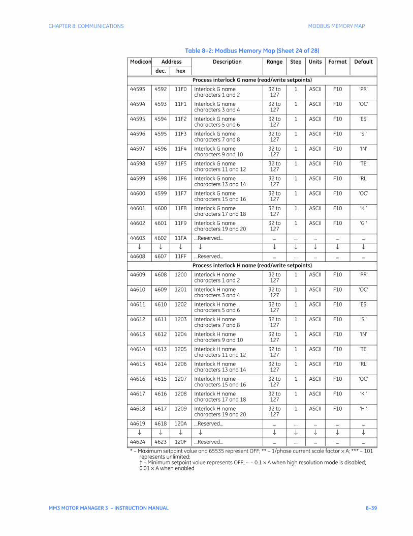
CHAPTER 8: COMMUNICATIONS MODBUS MEMORY MAP
MM3 MOTOR MANAGER 3 – INSTRUCTION MANUAL 8–39
Process interlock G name (read/write setpoints)
44593 4592 11F0 Interlock G name characters 1 and 2
32 to 127
1 ASCII F10 ‘PR’
44594 4593 11F1 Interlock G name characters 3 and 4
32 to 127
1 ASCII F10 ‘OC’
44595 4594 11F2 Interlock G name characters 5 and 6
32 to 127
1 ASCII F10 ‘ES’
44596 4595 11F3 Interlock G name characters 7 and 8
32 to 127
1 ASCII F10 ‘S ‘
44597 4596 11F4 Interlock G name characters 9 and 10
32 to 127
1 ASCII F10 ‘IN’
44598 4597 11F5 Interlock G name characters 11 and 12
32 to 127
1 ASCII F10 ‘TE’
44599 4598 11F6 Interlock G name characters 13 and 14
32 to 127
1 ASCII F10 ‘RL’
44600 4599 11F7 Interlock G name characters 15 and 16
32 to 127
1 ASCII F10 ‘OC’
44601 4600 11F8 Interlock G name characters 17 and 18
32 to 127
1 ASCII F10 ‘K ‘
44602 4601 11F9 Interlock G name characters 19 and 20
32 to 127
1 ASCII F10 ‘G ‘
44603 4602 11FA ...Reserved... ... ... ... ... ...
↓ ↓ ↓ ↓ ↓ ↓ ↓ ↓ ↓44608 4607 11FF ...Reserved... ... ... ... ... ...
Process interlock H name (read/write setpoints)
44609 4608 1200 Interlock H name characters 1 and 2
32 to 127
1 ASCII F10 ‘PR’
44610 4609 1201 Interlock H name characters 3 and 4
32 to 127
1 ASCII F10 ‘OC’
44611 4610 1202 Interlock H name characters 5 and 6
32 to 127
1 ASCII F10 ‘ES’
44612 4611 1203 Interlock H name characters 7 and 8
32 to 127
1 ASCII F10 ‘S ‘
44613 4612 1204 Interlock H name characters 9 and 10
32 to 127
1 ASCII F10 ‘IN’
44614 4613 1205 Interlock H name characters 11 and 12
32 to 127
1 ASCII F10 ‘TE’
44615 4614 1206 Interlock H name characters 13 and 14
32 to 127
1 ASCII F10 ‘RL’
44616 4615 1207 Interlock H name characters 15 and 16
32 to 127
1 ASCII F10 ‘OC’
44617 4616 1208 Interlock H name characters 17 and 18
32 to 127
1 ASCII F10 ‘K ‘
44618 4617 1209 Interlock H name characters 19 and 20
32 to 127
1 ASCII F10 ‘H ‘
44619 4618 120A ...Reserved... ... ... ... ... ...
↓ ↓ ↓ ↓ ↓ ↓ ↓ ↓ ↓44624 4623 120F ...Reserved... ... ... ... ... ...
Table 8–2: Modbus Memory Map (Sheet 24 of 28)
Modicon Address Description Range Step Units Format Default
dec. hex
* – Maximum setpoint value and 65535 represent OFF; ** – 1/phase current scale factor × A; *** – 101 represents unlimited;† – Minimum setpoint value represents OFF; ~ – 0.1 × A when high resolution mode is disabled; 0.01 × A when enabled
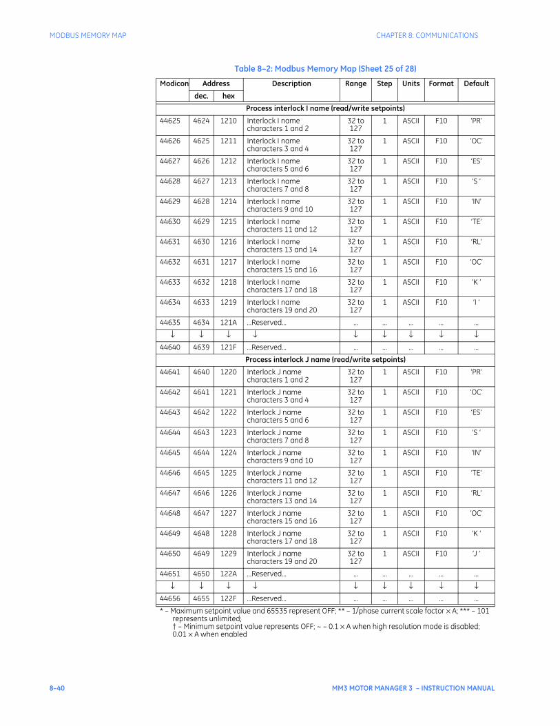
8–40 MM3 MOTOR MANAGER 3 – INSTRUCTION MANUAL
MODBUS MEMORY MAP CHAPTER 8: COMMUNICATIONS
Process interlock I name (read/write setpoints)
44625 4624 1210 Interlock I name characters 1 and 2
32 to 127
1 ASCII F10 ‘PR’
44626 4625 1211 Interlock I name characters 3 and 4
32 to 127
1 ASCII F10 ‘OC’
44627 4626 1212 Interlock I name characters 5 and 6
32 to 127
1 ASCII F10 ‘ES’
44628 4627 1213 Interlock I name characters 7 and 8
32 to 127
1 ASCII F10 ‘S ‘
44629 4628 1214 Interlock I name characters 9 and 10
32 to 127
1 ASCII F10 ‘IN’
44630 4629 1215 Interlock I name characters 11 and 12
32 to 127
1 ASCII F10 ‘TE’
44631 4630 1216 Interlock I name characters 13 and 14
32 to 127
1 ASCII F10 ‘RL’
44632 4631 1217 Interlock I name characters 15 and 16
32 to 127
1 ASCII F10 ‘OC’
44633 4632 1218 Interlock I name characters 17 and 18
32 to 127
1 ASCII F10 ‘K ‘
44634 4633 1219 Interlock I name characters 19 and 20
32 to 127
1 ASCII F10 ‘I ‘
44635 4634 121A ...Reserved... ... ... ... ... ...
↓ ↓ ↓ ↓ ↓ ↓ ↓ ↓ ↓44640 4639 121F ...Reserved... ... ... ... ... ...
Process interlock J name (read/write setpoints)
44641 4640 1220 Interlock J name characters 1 and 2
32 to 127
1 ASCII F10 ‘PR’
44642 4641 1221 Interlock J name characters 3 and 4
32 to 127
1 ASCII F10 ‘OC’
44643 4642 1222 Interlock J name characters 5 and 6
32 to 127
1 ASCII F10 ‘ES’
44644 4643 1223 Interlock J name characters 7 and 8
32 to 127
1 ASCII F10 ‘S ‘
44645 4644 1224 Interlock J name characters 9 and 10
32 to 127
1 ASCII F10 ‘IN’
44646 4645 1225 Interlock J name characters 11 and 12
32 to 127
1 ASCII F10 ‘TE’
44647 4646 1226 Interlock J name characters 13 and 14
32 to 127
1 ASCII F10 ‘RL’
44648 4647 1227 Interlock J name characters 15 and 16
32 to 127
1 ASCII F10 ‘OC’
44649 4648 1228 Interlock J name characters 17 and 18
32 to 127
1 ASCII F10 ‘K ‘
44650 4649 1229 Interlock J name characters 19 and 20
32 to 127
1 ASCII F10 ‘J ‘
44651 4650 122A ...Reserved... ... ... ... ... ...
↓ ↓ ↓ ↓ ↓ ↓ ↓ ↓ ↓44656 4655 122F ...Reserved... ... ... ... ... ...
Table 8–2: Modbus Memory Map (Sheet 25 of 28)
Modicon Address Description Range Step Units Format Default
dec. hex
* – Maximum setpoint value and 65535 represent OFF; ** – 1/phase current scale factor × A; *** – 101 represents unlimited;† – Minimum setpoint value represents OFF; ~ – 0.1 × A when high resolution mode is disabled; 0.01 × A when enabled
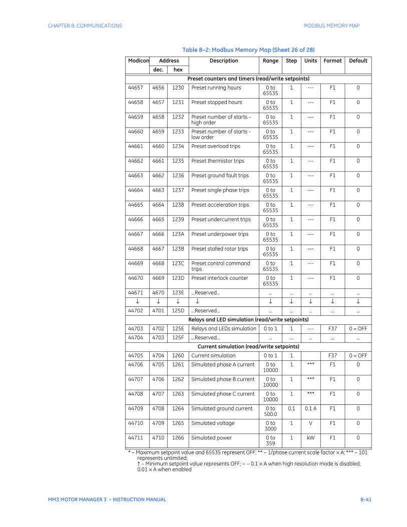
CHAPTER 8: COMMUNICATIONS MODBUS MEMORY MAP
MM3 MOTOR MANAGER 3 – INSTRUCTION MANUAL 8–41
Preset counters and timers (read/write setpoints)
44657 4656 1230 Preset running hours 0 to 65535
1 --- F1 0
44658 4657 1231 Preset stopped hours 0 to 65535
1 --- F1 0
44659 4658 1232 Preset number of starts - high order
0 to 65535
1 --- F1 0
44660 4659 1233 Preset number of starts - low order
0 to 65535
1 --- F1 0
44661 4660 1234 Preset overload trips 0 to 65535
1 --- F1 0
44662 4661 1235 Preset thermistor trips 0 to 65535
1 --- F1 0
44663 4662 1236 Preset ground fault trips 0 to 65535
1 --- F1 0
44664 4663 1237 Preset single phase trips 0 to 65535
1 --- F1 0
44665 4664 1238 Preset acceleration trips 0 to 65535
1 --- F1 0
44666 4665 1239 Preset undercurrent trips 0 to 65535
1 --- F1 0
44667 4666 123A Preset underpower trips 0 to 65535
1 --- F1 0
44668 4667 123B Preset stalled rotor trips 0 to 65535
1 --- F1 0
44669 4668 123C Preset control command trips
0 to 65535
1 --- F1 0
44670 4669 123D Preset interlock counter 0 to 65535
1 --- F1 0
44671 4670 123E ...Reserved... ... ... ... ... ...
↓ ↓ ↓ ↓ ↓ ↓ ↓ ↓ ↓44702 4701 125D ...Reserved... ... ... ... ... ...
Relays and LED simulation (read/write setpoints)
44703 4702 125E Relays and LEDs simulation 0 to 1 1 --- F37 0 = OFF
44704 4703 125F ...Reserved... ... ... ... ... ...
Current simulation (read/write setpoints)
44705 4704 1260 Current simulation 0 to 1 1 F37 0 = OFF
44706 4705 1261 Simulated phase A current 0 to 10000
1 *** F1 0
44707 4706 1262 Simulated phase B current 0 to 10000
1 *** F1 0
44708 4707 1263 Simulated phase C current 0 to 10000
1 *** F1 0
44709 4708 1264 Simulated ground current 0 to 500.0
0.1 0.1 A F1 0
44710 4709 1265 Simulated voltage 0 to 3000
1 V F1 0
44711 4710 1266 Simulated power 0 to 359
1 kW F1 0
Table 8–2: Modbus Memory Map (Sheet 26 of 28)
Modicon Address Description Range Step Units Format Default
dec. hex
* – Maximum setpoint value and 65535 represent OFF; ** – 1/phase current scale factor × A; *** – 101 represents unlimited;† – Minimum setpoint value represents OFF; ~ – 0.1 × A when high resolution mode is disabled; 0.01 × A when enabled
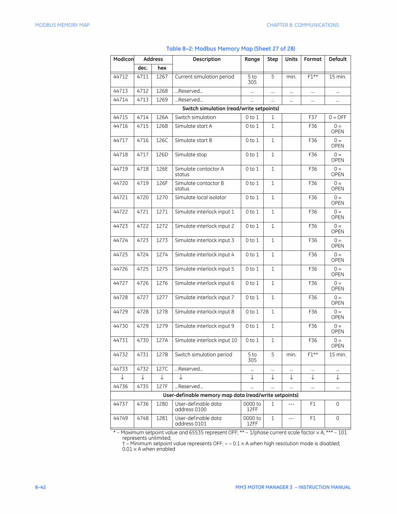
8–42 MM3 MOTOR MANAGER 3 – INSTRUCTION MANUAL
MODBUS MEMORY MAP CHAPTER 8: COMMUNICATIONS
44712 4711 1267 Current simulation period 5 to 305
5 min. F1** 15 min.
44713 4712 1268 ...Reserved... ... ... ... ... ...
44714 4713 1269 ...Reserved... ... ... ... ... ...
Switch simulation (read/write setpoints)
44715 4714 126A Switch simulation 0 to 1 1 F37 0 = OFF
44716 4715 126B Simulate start A 0 to 1 1 F36 0 = OPEN
44717 4716 126C Simulate start B 0 to 1 1 F36 0 = OPEN
44718 4717 126D Simulate stop 0 to 1 1 F36 0 = OPEN
44719 4718 126E Simulate contactor A status
0 to 1 1 F36 0 = OPEN
44720 4719 126F Simulate contactor B status
0 to 1 1 F36 0 = OPEN
44721 4720 1270 Simulate local isolator 0 to 1 1 F36 0 = OPEN
44722 4721 1271 Simulate interlock input 1 0 to 1 1 F36 0 = OPEN
44723 4722 1272 Simulate interlock input 2 0 to 1 1 F36 0 = OPEN
44724 4723 1273 Simulate interlock input 3 0 to 1 1 F36 0 = OPEN
44725 4724 1274 Simulate interlock input 4 0 to 1 1 F36 0 = OPEN
44726 4725 1275 Simulate interlock input 5 0 to 1 1 F36 0 = OPEN
44727 4726 1276 Simulate interlock input 6 0 to 1 1 F36 0 = OPEN
44728 4727 1277 Simulate interlock input 7 0 to 1 1 F36 0 = OPEN
44729 4728 1278 Simulate interlock input 8 0 to 1 1 F36 0 = OPEN
44730 4729 1279 Simulate interlock input 9 0 to 1 1 F36 0 = OPEN
44731 4730 127A Simulate interlock input 10 0 to 1 1 F36 0 = OPEN
44732 4731 127B Switch simulation period 5 to 305
5 min. F1** 15 min.
44733 4732 127C ...Reserved... ... ... ... ... ...
↓ ↓ ↓ ↓ ↓ ↓ ↓ ↓ ↓44736 4735 127F ...Reserved... ... ... ... ... ...
User-definable memory map data (read/write setpoints)
44737 4736 1280 User-definable data address 0100
0000 to 12FF
1 --- F1 0
44749 4748 1281 User-definable data address 0101
0000 to 12FF
1 --- F1 0
Table 8–2: Modbus Memory Map (Sheet 27 of 28)
Modicon Address Description Range Step Units Format Default
dec. hex
* – Maximum setpoint value and 65535 represent OFF; ** – 1/phase current scale factor × A; *** – 101 represents unlimited;† – Minimum setpoint value represents OFF; ~ – 0.1 × A when high resolution mode is disabled; 0.01 × A when enabled
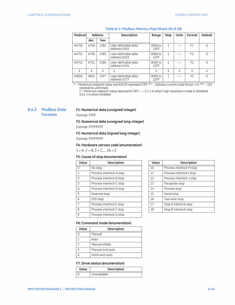
CHAPTER 8: COMMUNICATIONS MODBUS MEMORY MAP
MM3 MOTOR MANAGER 3 – INSTRUCTION MANUAL 8–43
8.4.2 Modbus Data Formats
F1: Numerical data (unsigned integer)Format: FFFF
F2: Numerical data (unsigned long integer)Format: FFFFFFFF
F3: Numerical data (signed long integer)Format: FFFFFFFF
F4: Hardware version code (enumeration)1 = A, 2 = B, 3 = C,..., 26 = Z
F5: Cause of stop (enumeration)
F6: Command mode (enumeration)
F7: Drive status (enumeration)
44750 4749 1282 User-definable data address 0102
0000 to 12FF
1 --- F1 0
44751 4750 1283 User-definable data address 0103
0000 to 12FF
1 --- F1 0
44752 4751 1284 User-definable data address 0104
0000 to 12FF
1 --- F1 0
↓ ↓ ↓ ↓ ↓ ↓ ↓ ↓ ↓44856 4855 12F7 User-definable data
address 01770000 to
12FF1 --- F1 0
Table 8–2: Modbus Memory Map (Sheet 28 of 28)
Modicon Address Description Range Step Units Format Default
dec. hex
* – Maximum setpoint value and 65535 represent OFF; ** – 1/phase current scale factor × A; *** – 101 represents unlimited;† – Minimum setpoint value represents OFF; ~ – 0.1 × A when high resolution mode is disabled; 0.01 × A when enabled
Value Description Value Description
0 No stop 10 Process interlock H stop
1 Process interlock A stop 11 Process interlock I stop
2 Process interlock B stop 12 Process interlock J stop
3 Process interlock C stop 13 Faceplate stop
4 Process interlock D stop 14 Process stop
5 External stop 15 Serial stop
6 ESD stop 16 Two-wire stop
7 Process interlock E stop 17 Stop A interlock stop
8 Process interlock F stop 18 Stop B interlock stop
9 Process interlock G stop
Value Description
0 Manual
1 Auto
2 Manual inhibit
3 Manual and auto
4 Hard-wire auto
Value Description
0 Unavailable
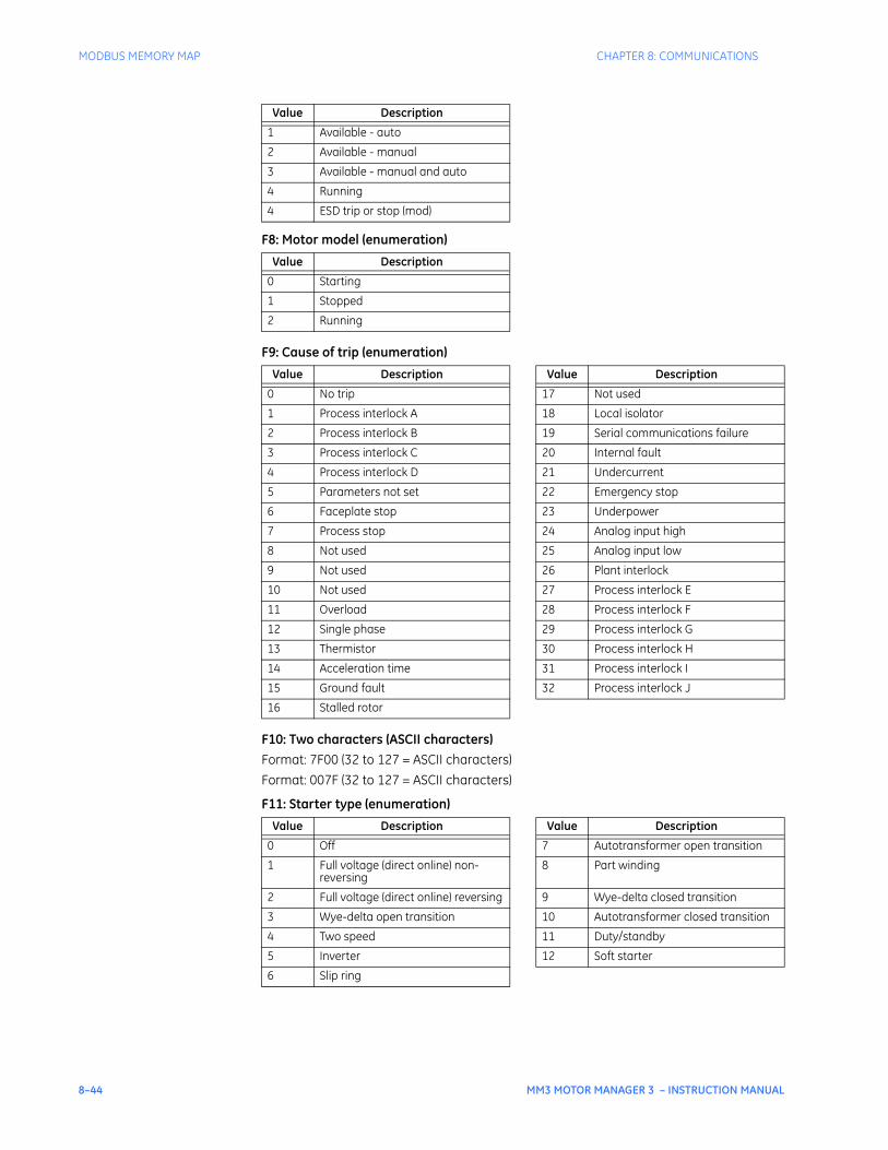
8–44 MM3 MOTOR MANAGER 3 – INSTRUCTION MANUAL
MODBUS MEMORY MAP CHAPTER 8: COMMUNICATIONS
F8: Motor model (enumeration)
F9: Cause of trip (enumeration)
F10: Two characters (ASCII characters)Format: 7F00 (32 to 127 = ASCII characters)Format: 007F (32 to 127 = ASCII characters)
F11: Starter type (enumeration)
1 Available - auto
2 Available - manual
3 Available - manual and auto
4 Running
4 ESD trip or stop (mod)
Value Description
0 Starting
1 Stopped
2 Running
Value Description Value Description
0 No trip 17 Not used
1 Process interlock A 18 Local isolator
2 Process interlock B 19 Serial communications failure
3 Process interlock C 20 Internal fault
4 Process interlock D 21 Undercurrent
5 Parameters not set 22 Emergency stop
6 Faceplate stop 23 Underpower
7 Process stop 24 Analog input high
8 Not used 25 Analog input low
9 Not used 26 Plant interlock
10 Not used 27 Process interlock E
11 Overload 28 Process interlock F
12 Single phase 29 Process interlock G
13 Thermistor 30 Process interlock H
14 Acceleration time 31 Process interlock I
15 Ground fault 32 Process interlock J
16 Stalled rotor
Value Description Value Description
0 Off 7 Autotransformer open transition
1 Full voltage (direct online) non-reversing
8 Part winding
2 Full voltage (direct online) reversing 9 Wye-delta closed transition
3 Wye-delta open transition 10 Autotransformer closed transition
4 Two speed 11 Duty/standby
5 Inverter 12 Soft starter
6 Slip ring
Value Description
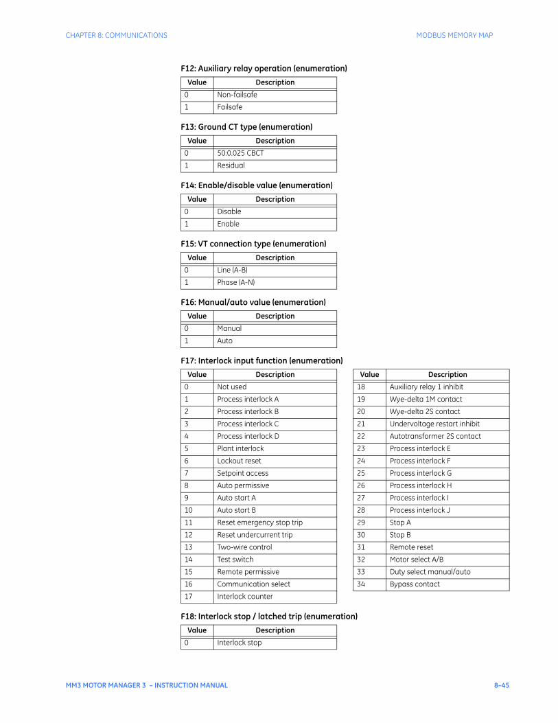
CHAPTER 8: COMMUNICATIONS MODBUS MEMORY MAP
MM3 MOTOR MANAGER 3 – INSTRUCTION MANUAL 8–45
F12: Auxiliary relay operation (enumeration)
F13: Ground CT type (enumeration)
F14: Enable/disable value (enumeration)
F15: VT connection type (enumeration)
F16: Manual/auto value (enumeration)
F17: Interlock input function (enumeration)
F18: Interlock stop / latched trip (enumeration)
Value Description
0 Non-failsafe
1 Failsafe
Value Description
0 50:0.025 CBCT
1 Residual
Value Description
0 Disable
1 Enable
Value Description
0 Line (A-B)
1 Phase (A-N)
Value Description
0 Manual
1 Auto
Value Description Value Description
0 Not used 18 Auxiliary relay 1 inhibit
1 Process interlock A 19 Wye-delta 1M contact
2 Process interlock B 20 Wye-delta 2S contact
3 Process interlock C 21 Undervoltage restart inhibit
4 Process interlock D 22 Autotransformer 2S contact
5 Plant interlock 23 Process interlock E
6 Lockout reset 24 Process interlock F
7 Setpoint access 25 Process interlock G
8 Auto permissive 26 Process interlock H
9 Auto start A 27 Process interlock I
10 Auto start B 28 Process interlock J
11 Reset emergency stop trip 29 Stop A
12 Reset undercurrent trip 30 Stop B
13 Two-wire control 31 Remote reset
14 Test switch 32 Motor select A/B
15 Remote permissive 33 Duty select manual/auto
16 Communication select 34 Bypass contact
17 Interlock counter
Value Description
0 Interlock stop
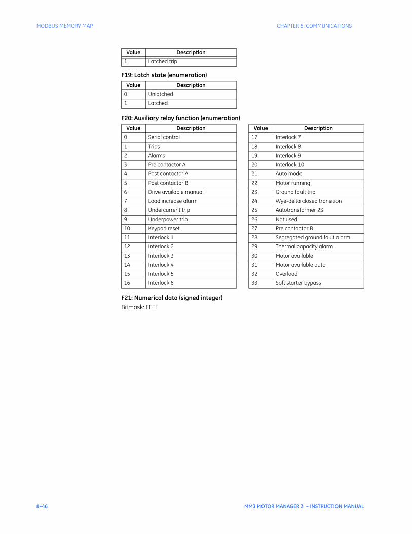
8–46 MM3 MOTOR MANAGER 3 – INSTRUCTION MANUAL
MODBUS MEMORY MAP CHAPTER 8: COMMUNICATIONS
F19: Latch state (enumeration)
F20: Auxiliary relay function (enumeration)
F21: Numerical data (signed integer)Bitmask: FFFF
1 Latched trip
Value Description
0 Unlatched
1 Latched
Value Description Value Description
0 Serial control 17 Interlock 7
1 Trips 18 Interlock 8
2 Alarms 19 Interlock 9
3 Pre contactor A 20 Interlock 10
4 Post contactor A 21 Auto mode
5 Post contactor B 22 Motor running
6 Drive available manual 23 Ground fault trip
7 Load increase alarm 24 Wye-delta closed transition
8 Undercurrent trip 25 Autotransformer 2S
9 Underpower trip 26 Not used
10 Keypad reset 27 Pre contactor B
11 Interlock 1 28 Segregated ground fault alarm
12 Interlock 2 29 Thermal capacity alarm
13 Interlock 3 30 Motor available
14 Interlock 4 31 Motor available auto
15 Interlock 5 32 Overload
16 Interlock 6 33 Soft starter bypass
Value Description
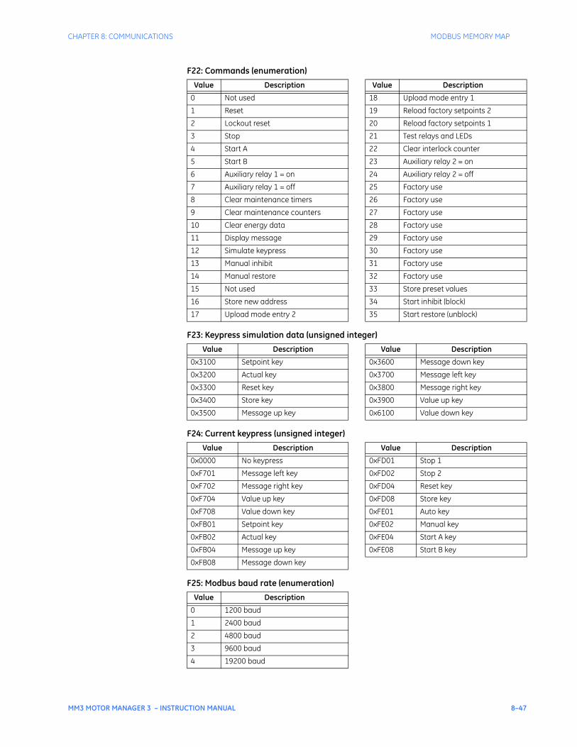
CHAPTER 8: COMMUNICATIONS MODBUS MEMORY MAP
MM3 MOTOR MANAGER 3 – INSTRUCTION MANUAL 8–47
F22: Commands (enumeration)
F23: Keypress simulation data (unsigned integer)
F24: Current keypress (unsigned integer)
F25: Modbus baud rate (enumeration)
Value Description Value Description
0 Not used 18 Upload mode entry 1
1 Reset 19 Reload factory setpoints 2
2 Lockout reset 20 Reload factory setpoints 1
3 Stop 21 Test relays and LEDs
4 Start A 22 Clear interlock counter
5 Start B 23 Auxiliary relay 2 = on
6 Auxiliary relay 1 = on 24 Auxiliary relay 2 = off
7 Auxiliary relay 1 = off 25 Factory use
8 Clear maintenance timers 26 Factory use
9 Clear maintenance counters 27 Factory use
10 Clear energy data 28 Factory use
11 Display message 29 Factory use
12 Simulate keypress 30 Factory use
13 Manual inhibit 31 Factory use
14 Manual restore 32 Factory use
15 Not used 33 Store preset values
16 Store new address 34 Start inhibit (block)
17 Upload mode entry 2 35 Start restore (unblock)
Value Description Value Description
0x3100 Setpoint key 0x3600 Message down key
0x3200 Actual key 0x3700 Message left key
0x3300 Reset key 0x3800 Message right key
0x3400 Store key 0x3900 Value up key
0x3500 Message up key 0x6100 Value down key
Value Description Value Description
0x0000 No keypress 0xFD01 Stop 1
0xF701 Message left key 0xFD02 Stop 2
0xF702 Message right key 0xFD04 Reset key
0xF704 Value up key 0xFD08 Store key
0xF708 Value down key 0xFE01 Auto key
0xFB01 Setpoint key 0xFE02 Manual key
0xFB02 Actual key 0xFE04 Start A key
0xFB04 Message up key 0xFE08 Start B key
0xFB08 Message down key
Value Description
0 1200 baud
1 2400 baud
2 4800 baud
3 9600 baud
4 19200 baud
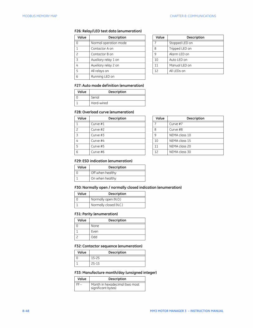
8–48 MM3 MOTOR MANAGER 3 – INSTRUCTION MANUAL
MODBUS MEMORY MAP CHAPTER 8: COMMUNICATIONS
F26: Relay/LED test data (enumeration)
F27: Auto mode definition (enumeration)
F28: Overload curve (enumeration)
F29: ESD indication (enumeration)
F30: Normally open / normally closed indication (enumeration)
F31: Parity (enumeration)
F32: Contactor sequence (enumeration)
F33: Manufacture month/day (unsigned integer)
Value Description Value Description
0 Normal operation mode 7 Stopped LED on
1 Contactor A on 8 Tripped LED on
2 Contactor B on 9 Alarm LED on
3 Auxiliary relay 1 on 10 Auto LED on
4 Auxiliary relay 2 on 11 Manual LED on
5 All relays on 12 All LEDs on
6 Running LED on
Value Description
0 Serial
1 Hard-wired
Value Description Value Description
1 Curve #1 7 Curve #7
2 Curve #2 8 Curve #8
3 Curve #3 9 NEMA class 10
4 Curve #4 10 NEMA class 15
5 Curve #5 11 NEMA class 20
6 Curve #6 12 NEMA class 30
Value Description
0 Off when healthy
1 On when healthy
Value Description
0 Normally open (N.O.)
1 Normally closed (N.C.)
Value Description
0 None
1 Even
2 Odd
Value Description
0 1S-2S
1 2S-1S
Value Description
FF-- Month in hexadecimal (two most significant bytes)
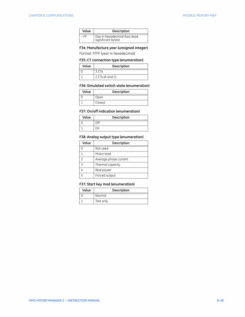
CHAPTER 8: COMMUNICATIONS MODBUS MEMORY MAP
MM3 MOTOR MANAGER 3 – INSTRUCTION MANUAL 8–49
F34: Manufacture year (unsigned integer)Format: FFFF (year in hexadecimal)
F35: CT connection type (enumeration)
F36: Simulated switch state (enumeration)
F37: On/off indication (enumeration)
F38: Analog output type (enumeration)
F37: Start key mod (enumeration)
--FF Day in hexadecimal (two least significant bytes)
Value Description
0 3 CTs
1 2 CTs (A and C)
Value Description
0 Open
1 Closed
Value Description
0 Off
1 On
Value Description
0 Not used
1 Motor load
2 Average phase current
3 Thermal capacity
4 Real power
5 Forced output
Value Description
0 Normal
1 Test only
Value Description
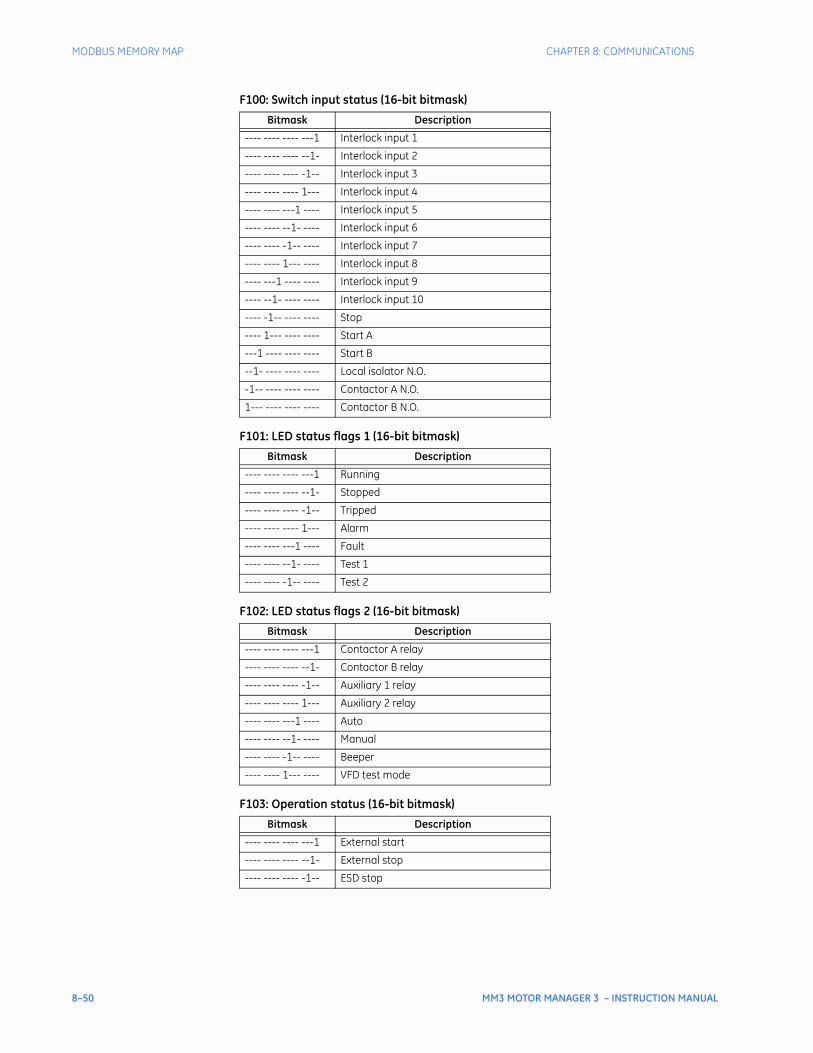
8–50 MM3 MOTOR MANAGER 3 – INSTRUCTION MANUAL
MODBUS MEMORY MAP CHAPTER 8: COMMUNICATIONS
F100: Switch input status (16-bit bitmask)
F101: LED status flags 1 (16-bit bitmask)
F102: LED status flags 2 (16-bit bitmask)
F103: Operation status (16-bit bitmask)
Bitmask Description
---- ---- ---- ---1 Interlock input 1
---- ---- ---- --1- Interlock input 2
---- ---- ---- -1-- Interlock input 3
---- ---- ---- 1--- Interlock input 4
---- ---- ---1 ---- Interlock input 5
---- ---- --1- ---- Interlock input 6
---- ---- -1-- ---- Interlock input 7
---- ---- 1--- ---- Interlock input 8
---- ---1 ---- ---- Interlock input 9
---- --1- ---- ---- Interlock input 10
---- -1-- ---- ---- Stop
---- 1--- ---- ---- Start A
---1 ---- ---- ---- Start B
--1- ---- ---- ---- Local isolator N.O.
-1-- ---- ---- ---- Contactor A N.O.
1--- ---- ---- ---- Contactor B N.O.
Bitmask Description
---- ---- ---- ---1 Running
---- ---- ---- --1- Stopped
---- ---- ---- -1-- Tripped
---- ---- ---- 1--- Alarm
---- ---- ---1 ---- Fault
---- ---- --1- ---- Test 1
---- ---- -1-- ---- Test 2
Bitmask Description
---- ---- ---- ---1 Contactor A relay
---- ---- ---- --1- Contactor B relay
---- ---- ---- -1-- Auxiliary 1 relay
---- ---- ---- 1--- Auxiliary 2 relay
---- ---- ---1 ---- Auto
---- ---- --1- ---- Manual
---- ---- -1-- ---- Beeper
---- ---- 1--- ---- VFD test mode
Bitmask Description
---- ---- ---- ---1 External start
---- ---- ---- --1- External stop
---- ---- ---- -1-- ESD stop
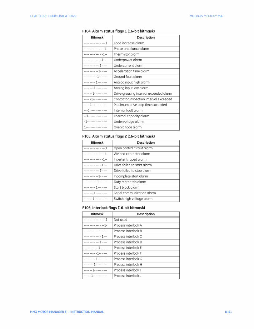
CHAPTER 8: COMMUNICATIONS MODBUS MEMORY MAP
MM3 MOTOR MANAGER 3 – INSTRUCTION MANUAL 8–51
F104: Alarm status flags 1 (16-bit bitmask)
F105: Alarm status flags 2 (16-bit bitmask)
F106: Interlock flags (16-bit bitmask)
Bitmask Description
---- ---- ---- ---1 Load increase alarm
---- ---- ---- --1- Phase unbalance alarm
---- ---- ---- -1-- Thermistor alarm
---- ---- ---- 1--- Underpower alarm
---- ---- ---1 ---- Undercurrent alarm
---- ---- --1- ---- Acceleration time alarm
---- ---- -1-- ---- Ground fault alarm
---- ---- 1--- ---- Analog input high alarm
---- ---1 ---- ---- Analog input low alarm
---- --1- ---- ---- Drive greasing interval exceeded alarm
---- -1-- ---- ---- Contactor inspection interval exceeded
---- 1--- ---- ---- Maximum drive stop time exceeded
---1 ---- ---- ---- Internal fault alarm
--1- ---- ---- ---- Thermal capacity alarm
-1-- ---- ---- ---- Undervoltage alarm
1--- ---- ---- ---- Overvoltage alarm
Bitmask Description
---- ---- ---- ---1 Open control circuit alarm
---- ---- ---- --1- Welded contactor alarm
---- ---- ---- -1-- Inverter tripped alarm
---- ---- ---- 1--- Drive failed to start alarm
---- ---- ---1 ---- Drive failed to stop alarm
---- ---- --1- ---- Incomplete start alarm
---- ---- -1-- ---- Duty motor trip alarm
---- ---- 1--- ---- Start block alarm
---- ---1 ---- ---- Serial communication alarm
---- --1- ---- ---- Switch high voltage alarm
Bitmask Description
---- ---- ---- ---1 Not used
---- ---- ---- --1- Process interlock A
---- ---- ---- -1-- Process interlock B
---- ---- ---- 1--- Process interlock C
---- ---- ---1 ---- Process interlock D
---- ---- --1- ---- Process interlock E
---- ---- -1-- ---- Process interlock F
---- ---- 1--- ---- Process interlock G
---- ---1 ---- ---- Process interlock H
---- --1- ---- ---- Process interlock I
---- -1-- ---- ---- Process interlock J
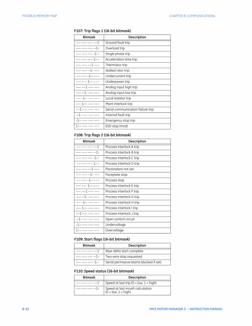
8–52 MM3 MOTOR MANAGER 3 – INSTRUCTION MANUAL
MODBUS MEMORY MAP CHAPTER 8: COMMUNICATIONS
F107: Trip flags 1 (16-bit bitmask)
F108: Trip flags 2 (16-bit bitmask)
F109: Start flags (16-bit bitmask)
F110: Speed status (16-bit bitmask)
Bitmask Description
---- ---- ---- ---1 Ground fault trip
---- ---- ---- --1- Overload trip
---- ---- ---- -1-- Single phase trip
---- ---- ---- 1--- Acceleration time trip
---- ---- ---1 ---- Thermistor trip
---- ---- --1- ---- Stalled rotor trip
---- ---- -1-- ---- Undercurrent trip
---- ---- 1--- ---- Underpower trip
---- ---1 ---- ---- Analog input high trip
---- --1- ---- ---- Analog input low trip
---- -1-- ---- ---- Local isolator trip
---- 1--- ---- ---- Plant interlock trip
---1 ---- ---- ---- Serial communication failure trip
--1- ---- ---- ---- Internal fault trip
-1-- ---- ---- ---- Emergency stop trip
1--- ---- ---- ---- ESD stop (mod)
Bitmask Description
---- ---- ---- ---1 Process interlock A trip
---- ---- ---- --1- Process interlock B trip
---- ---- ---- -1-- Process interlock C trip
---- ---- ---- 1--- Process interlock D trip
---- ---- ---1 ---- Parameters not set
---- ---- --1- ---- Faceplate stop
---- ---- -1-- ---- Process stop
---- ---- 1--- ---- Process interlock E trip
---- ---1 ---- ---- Process interlock F trip
---- --1- ---- ---- Process interlock G trip
---- -1-- ---- ---- Process interlock H trip
---- 1--- ---- ---- Process interlock I trip
---1 ---- ---- ---- Process interlock J trip
--1- ---- ---- ---- Open control circuit
-1-- ---- ---- ---- Undervoltage
1--- ---- ---- ---- Overvoltage
Bitmask Description
---- ---- ---- ---1 Wye-delta start complete
---- ---- ---- --1- Two-wire stop requested
---- ---- ---- -1-- Serial permissive (starts blocked if set)
Bitmask Description
---- ---- ---- ---1 Speed at last trip (0 = low, 1 = high)
---- ---- ---- --1- Speed at last inrush calculation(0 = low, 1 = high)
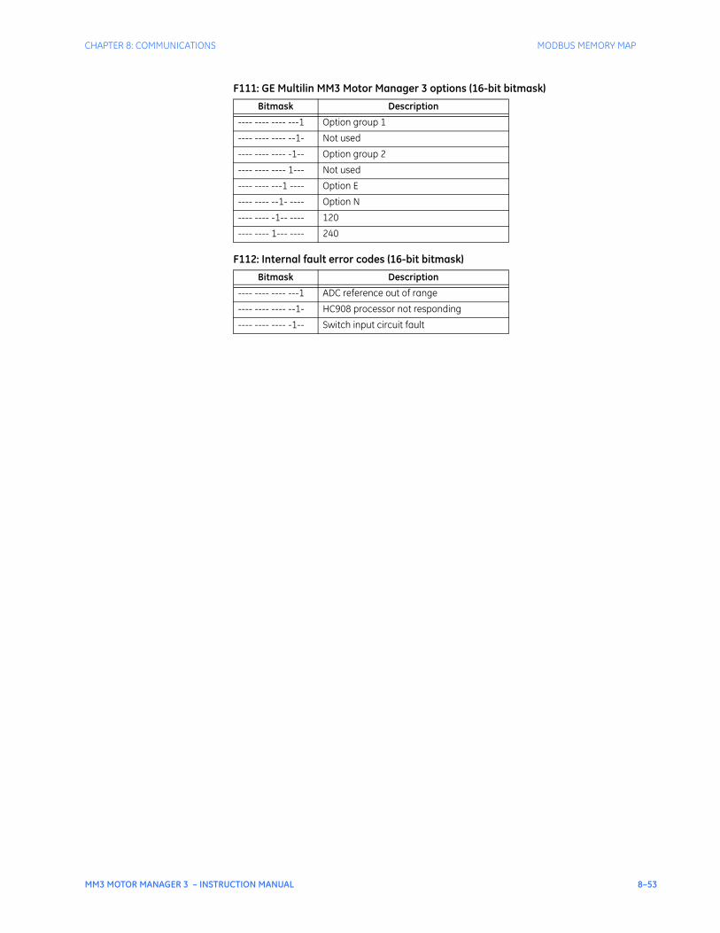
CHAPTER 8: COMMUNICATIONS MODBUS MEMORY MAP
MM3 MOTOR MANAGER 3 – INSTRUCTION MANUAL 8–53
F111: GE Multilin MM3 Motor Manager 3 options (16-bit bitmask)
F112: Internal fault error codes (16-bit bitmask)
Bitmask Description
---- ---- ---- ---1 Option group 1
---- ---- ---- --1- Not used
---- ---- ---- -1-- Option group 2
---- ---- ---- 1--- Not used
---- ---- ---1 ---- Option E
---- ---- --1- ---- Option N
---- ---- -1-- ---- 120
---- ---- 1--- ---- 240
Bitmask Description
---- ---- ---- ---1 ADC reference out of range
---- ---- ---- --1- HC908 processor not responding
---- ---- ---- -1-- Switch input circuit fault

8–54 MM3 MOTOR MANAGER 3 – INSTRUCTION MANUAL
MODBUS MEMORY MAP CHAPTER 8: COMMUNICATIONS
MM3 MOTOR MANAGER 3 – INSTRUCTION MANUAL 9–1
MM3 Motor Manager 3
Chapter 9: Applications
GE Consumer & IndustrialMultilin
STOP
RUNNING RELAY ARELAY A
STOPPED RELAY BRELAY B
TRIPPED AUX RELAY 1AUX RELAY 1
ALARM AUX RELAY 2AUX RELAY 2
VALUE
MESSAGE
AUTO MANUAL
STORE
RESET
ACTUAL
SETPOINT
START
A
START
A
START
B
START
B
Applications
9.1 Control Wire Applications
9.1.1 Two-wire Control
This control scheme is used when a maintained contact is in series with the starter coil. When the PLC contact is closed the motor runs. When the PLC contact opens the motor stops.
To program the MM3 Motor Manager 3 for two-wire control, set:
S3 PROCESS PROGRAMMABLE INPUTS INTERLOCK INPUT 1: “TWO WIRE CONTROL”S3 PROCESS STOP CONFIGURATION FACEPLATE STOP: “LATCHED”
The INTERLOCK INPUT 1 setpoint was chosen to match the wiring diagram provided. Any of the available Interlocks 1 through 10 could be programmed for two-wire control.
START operation:
• Start command received (switch input) and maintained.
STOP operation:
• Start command removed.
• Pressing the STOP key causes a latched trip. The motor cannot be restarted until RESET is pressed.
Terminal 11 (Stop input) must be closed to allow a start. The MM3 Motor Manager 3 display will read MOTOR STATUS UNAVAILABLE when the stop input is open.
If feedback is not received by the Contactor A relay Status N.O. inputs within 1 second of closing contactor A output relay, an OPEN CONTROL CIRCUIT alarm will occur. This will cause contactor A output relay to open.
NOTE
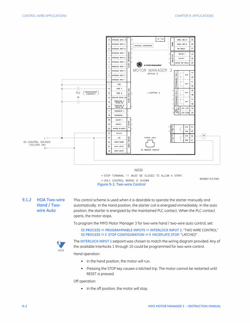
9–2 MM3 MOTOR MANAGER 3 – INSTRUCTION MANUAL
CONTROL WIRE APPLICATIONS CHAPTER 9: APPLICATIONS
Figure 9-1: Two-wire Control
9.1.2 HOA Two-wire Hand / Two-wire Auto
This control scheme is used when it is desirable to operate the starter manually and automatically. In the Hand position, the starter coil is energized immediately. In the auto position, the starter is energized by the maintained PLC contact. When the PLC contact opens, the motor stops.
To program the MM3 Motor Manager 3 for two-wire hand / two-wire auto control, set:
S3 PROCESS PROGRAMMABLE INPUTS INTERLOCK INPUT 1: “TWO WIRE CONTROL”S3 PROCESS STOP CONFIGURATION FACEPLATE STOP: “LATCHED”
The INTERLOCK INPUT 1 setpoint was chosen to match the wiring diagram provided. Any of the available Interlocks 1 through 10 could be programmed for two-wire control.
Hand operation:
• In the hand position, the motor will run.
• Pressing the STOP key causes a latched trip. The motor cannot be restarted until RESET is pressed.
Off operation:
• In the off position, the motor will stop.
GE POWER MANAGEMENT
NOTE
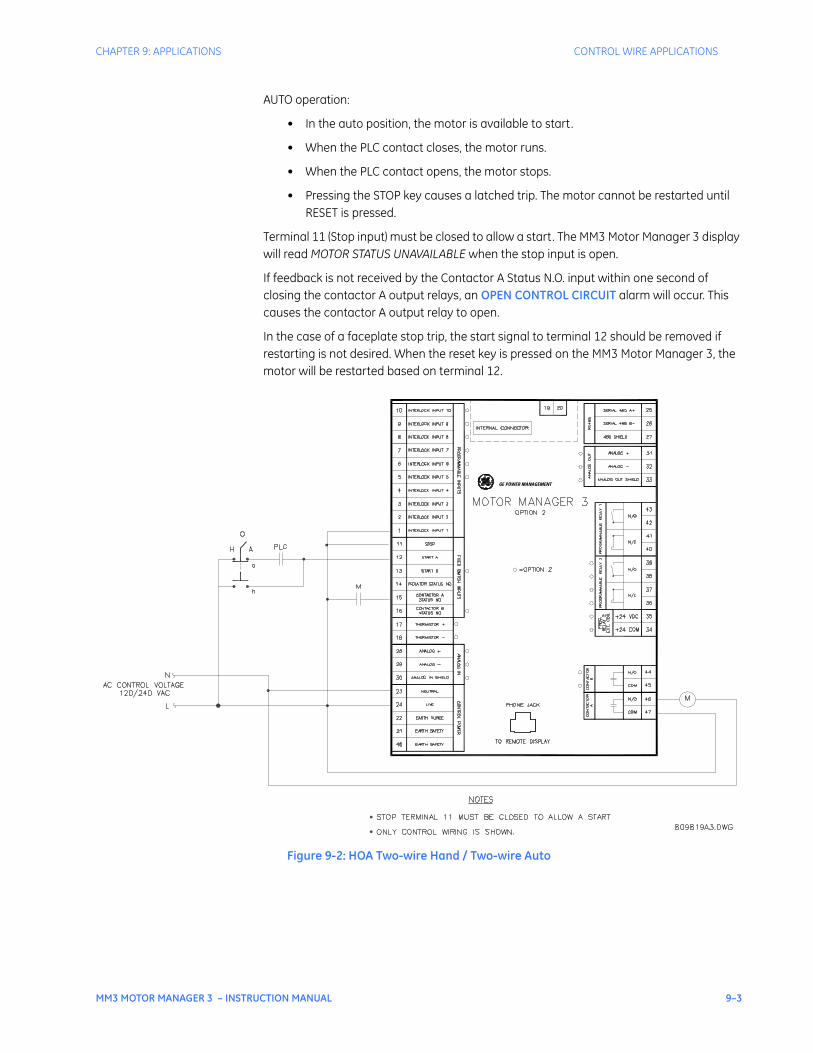
CHAPTER 9: APPLICATIONS CONTROL WIRE APPLICATIONS
MM3 MOTOR MANAGER 3 – INSTRUCTION MANUAL 9–3
AUTO operation:
• In the auto position, the motor is available to start.
• When the PLC contact closes, the motor runs.
• When the PLC contact opens, the motor stops.
• Pressing the STOP key causes a latched trip. The motor cannot be restarted until RESET is pressed.
Terminal 11 (Stop input) must be closed to allow a start. The MM3 Motor Manager 3 display will read MOTOR STATUS UNAVAILABLE when the stop input is open.
If feedback is not received by the Contactor A Status N.O. input within one second of closing the contactor A output relays, an OPEN CONTROL CIRCUIT alarm will occur. This causes the contactor A output relay to open.
In the case of a faceplate stop trip, the start signal to terminal 12 should be removed if restarting is not desired. When the reset key is pressed on the MM3 Motor Manager 3, the motor will be restarted based on terminal 12.
Figure 9-2: HOA Two-wire Hand / Two-wire Auto
GE POWER MANAGEMENT

9–4 MM3 MOTOR MANAGER 3 – INSTRUCTION MANUAL
CONTROL WIRE APPLICATIONS CHAPTER 9: APPLICATIONS
9.1.3 HOA Three-wire Hand / Two-wire Auto
This control scheme is used when it is desirable to operate the starter manually and automatically. In the Hand position, the starter coil is energized via the START button and de-energized via the STOP button. In the auto position, the starter is energized by the maintained PLC contact. When the PLC contact opens, the motor stops.
To program the MM3 Motor Manager 3 for three-wire hand / two-wire auto control, set:
S3 PROCESS PROGRAMMABLE INPUTS INTERLOCK INPUT 1: “TWO WIRE CONTROL”S3 PROCESS STOP CONFIGURATION FACEPLATE STOP: “LATCHED”
The INTERLOCK INPUT 1 setpoint was chosen to match the wiring diagram provided. Any of the available Interlocks 1 through 10 could be programmed for two-wire control.
HAND operation:
• In the hand position, the motor is available to start.
• When the START button is pressed, the motor will run.
• When the STOP button is pressed, the motor will stop.
• Pressing the STOP key causes a latched trip. The motor cannot be restarted until RESET is pressed.
OFF operation:
• In the off position, the motor will stop.
AUTO operation:
• In the auto position, the motor is available to start.
• When the PLC contact closes the motor runs.
• When the PLC contact opens the motor stops.
• When the faceplate stop key is pressed, it causes a latched trip. The motor cannot be restarted until reset is pressed.
Terminal 11 (stop input) must be closed to allow a start. The MM3 Motor Manager 3 display will read MOTOR STATUS UNAVAILABLE when the stop input is open.
If feedback is not received by the Contactor A Status N.O. input within one second of closing Contactor A output relay, an OPEN CONTROL CIRCUIT alarm will occur. This will cause Contactor A output relay to open.
In the auto position the STOP button at the motor will not STOP the motor.
NOTE
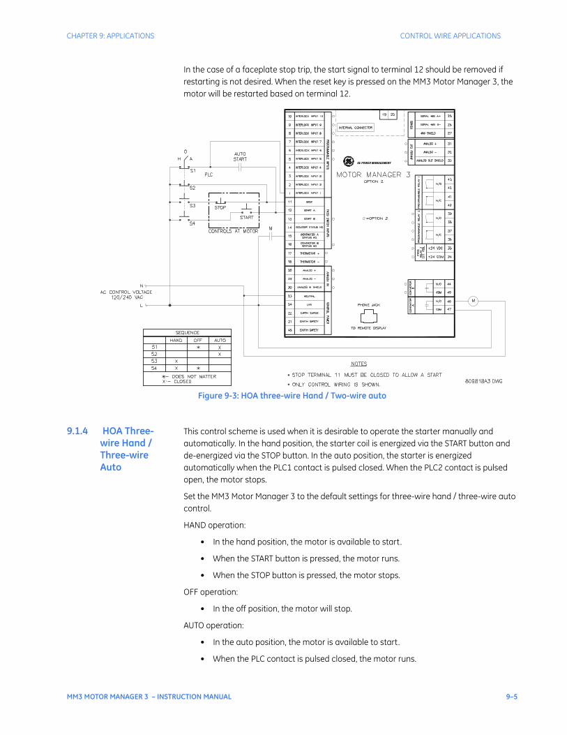
CHAPTER 9: APPLICATIONS CONTROL WIRE APPLICATIONS
MM3 MOTOR MANAGER 3 – INSTRUCTION MANUAL 9–5
In the case of a faceplate stop trip, the start signal to terminal 12 should be removed if restarting is not desired. When the reset key is pressed on the MM3 Motor Manager 3, the motor will be restarted based on terminal 12.
Figure 9-3: HOA three-wire Hand / Two-wire auto
9.1.4 HOA Three-wire Hand / Three-wire Auto
This control scheme is used when it is desirable to operate the starter manually and automatically. In the hand position, the starter coil is energized via the START button and de-energized via the STOP button. In the auto position, the starter is energized automatically when the PLC1 contact is pulsed closed. When the PLC2 contact is pulsed open, the motor stops.
Set the MM3 Motor Manager 3 to the default settings for three-wire hand / three-wire auto control.
HAND operation:
• In the hand position, the motor is available to start.
• When the START button is pressed, the motor runs.
• When the STOP button is pressed, the motor stops.
OFF operation:
• In the off position, the motor will stop.
AUTO operation:
• In the auto position, the motor is available to start.
• When the PLC contact is pulsed closed, the motor runs.
GE POWER MANAGEMENT
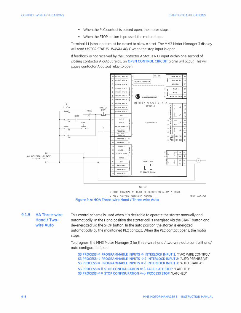
9–6 MM3 MOTOR MANAGER 3 – INSTRUCTION MANUAL
CONTROL WIRE APPLICATIONS CHAPTER 9: APPLICATIONS
• When the PLC contact is pulsed open, the motor stops.
• When the STOP button is pressed, the motor stops.
Terminal 11 (stop input) must be closed to allow a start. The MM3 Motor Manager 3 display will read MOTOR STATUS UNAVAILABLE when the stop input is open.
If feedback is not received by the Contactor A Status N.O. input within one second of closing contactor A output relay, an OPEN CONTROL CIRCUIT alarm will occur. This will cause contactor A output relay to open.
Figure 9-4: HOA Three-wire Hand / Three-wire Auto
9.1.5 HA Three-wire Hand / Two-wire Auto
This control scheme is used when it is desirable to operate the starter manually and automatically. In the Hand position the starter coil is energized via the START button and de-energized via the STOP button. In the auto position the starter is energized automatically by the maintained PLC contact. When the PLC contact opens, the motor stops.
To program the MM3 Motor Manager 3 for three-wire hand / two-wire auto control (hand/auto configuration), set:
S3 PROCESS PROGRAMMABLE INPUTS INTERLOCK INPUT 1: “TWO WIRE CONTROL”S3 PROCESS PROGRAMMABLE INPUTS INTERLOCK INPUT 2: “AUTO PERMISSIVE”S3 PROCESS PROGRAMMABLE INPUTS INTERLOCK INPUT 3: “AUTO START A”
S3 PROCESS STOP CONFIGURATION FACEPLATE STOP: “LATCHED”S3 PROCESS STOP CONFIGURATION PROCESS STOP: “LATCHED”
GE POWER MANAGEMENT

CHAPTER 9: APPLICATIONS CONTROL WIRE APPLICATIONS
MM3 MOTOR MANAGER 3 – INSTRUCTION MANUAL 9–7
The INTERLOCK INPUT 1(3) setpoints were chosen to match the wiring diagram provided. Any of the available Interlocks 1 through 10 could be programmed for two-wire control, auto-permissive, or auto start A.
HAND operation:
• In the hand position, the motor is available to start.
• When the START button is pressed, the motor runs.
• When the STOP button is pressed, the motor stops and a latched trip is generated. The motor cannot be restarted until reset is pressed.
• When the faceplate stop key is pressed, it causes a latched trip. The motor cannot be restarted until reset is pressed.
AUTO operation:
• In the auto position, the motor is available to start.
• When the PLC contact closes, the motor runs.
• When the PLC contact opens, the motor stops and a latched trip is generated. The motor cannot be restarted until reset is pressed.
• When the faceplate stop key is pressed, it causes a latched trip. The motor cannot be restarted until reset is pressed.
• Start commands from the faceplate, serial port and terminals 12,53 are blocked.
Terminal 11 (stop input) must be closed to allow a start. The MM3 Motor Manager 3 display will read MOTOR STATUS UNAVAILABLE when the stop input is open.
If feedback is not received by the Contactor A Status N.O. input within 1 second of closing contactor A output relay, an OPEN CONTROL CIRCUIT alarm will occur. This will cause contactor A output relay to open.
In the case of a faceplate or process stop trip, the start signal to terminal 43 should be removed if restarting is not desired. When the MM3 Motor Manager 3 reset key is pressed, the motor will be restarted based on terminal 43.
The STOP button at the motor remains active in the auto mode.
NOTE
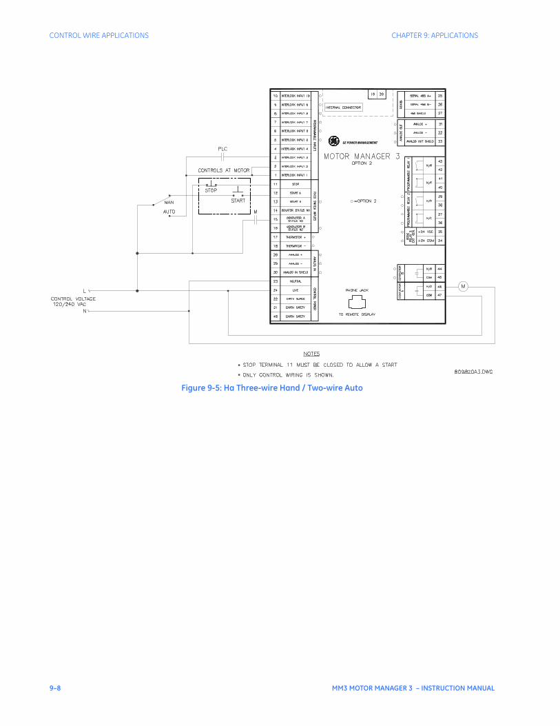
9–8 MM3 MOTOR MANAGER 3 – INSTRUCTION MANUAL
CONTROL WIRE APPLICATIONS CHAPTER 9: APPLICATIONS
Figure 9-5: Ha Three-wire Hand / Two-wire Auto
GE POWER MANAGEMENT
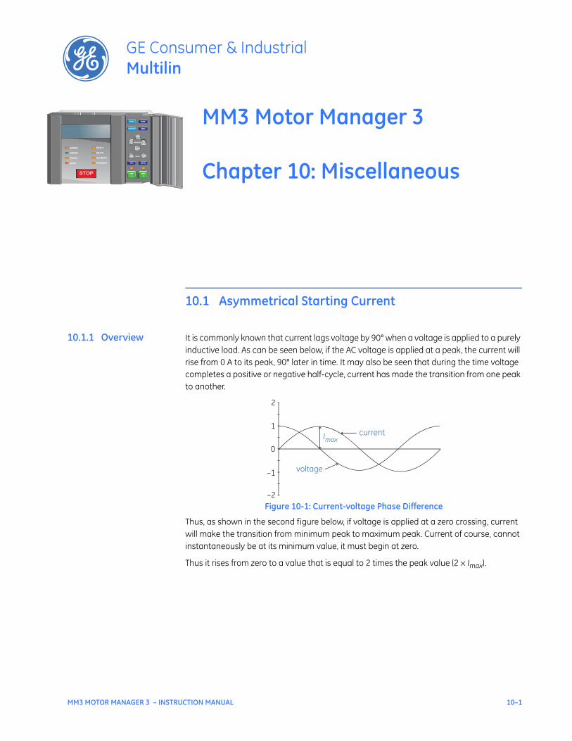
MM3 MOTOR MANAGER 3 – INSTRUCTION MANUAL 10–1
MM3 Motor Manager 3
Chapter 10: Miscellaneous
GE Consumer & IndustrialMultilin
STOP
RUNNING RELAY ARELAY A
STOPPED RELAY BRELAY B
TRIPPED AUX RELAY 1AUX RELAY 1
ALARM AUX RELAY 2AUX RELAY 2
VALUE
MESSAGE
AUTO MANUAL
STORE
RESET
ACTUAL
SETPOINT
START
A
START
A
START
B
START
B
Miscellaneous
10.1 Asymmetrical Starting Current
10.1.1 Overview It is commonly known that current lags voltage by 90° when a voltage is applied to a purely inductive load. As can be seen below, if the AC voltage is applied at a peak, the current will rise from 0 A to its peak, 90° later in time. It may also be seen that during the time voltage completes a positive or negative half-cycle, current has made the transition from one peak to another.
Figure 10-1: Current-voltage Phase Difference
Thus, as shown in the second figure below, if voltage is applied at a zero crossing, current will make the transition from minimum peak to maximum peak. Current of course, cannot instantaneously be at its minimum value, it must begin at zero.
Thus it rises from zero to a value that is equal to 2 times the peak value (2 × Imax).
currentImax
voltage
2
1
0
–1
–2
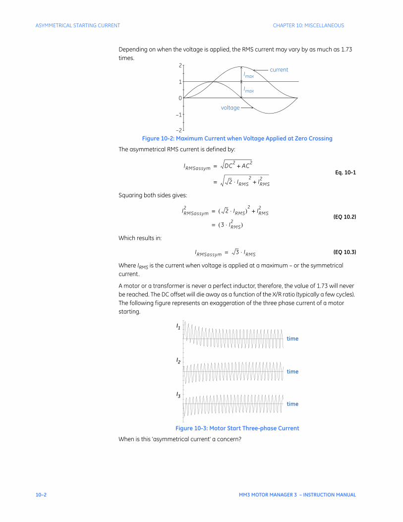
10–2 MM3 MOTOR MANAGER 3 – INSTRUCTION MANUAL
ASYMMETRICAL STARTING CURRENT CHAPTER 10: MISCELLANEOUS
Depending on when the voltage is applied, the RMS current may vary by as much as 1.73 times.
Figure 10-2: Maximum Current when Voltage Applied at Zero Crossing
The asymmetrical RMS current is defined by:
Eq. 10-1
Squaring both sides gives:
(EQ 10.2)
Which results in:
(EQ 10.3)
Where IRMS is the current when voltage is applied at a maximum – or the symmetrical current.
A motor or a transformer is never a perfect inductor, therefore, the value of 1.73 will never be reached. The DC offset will die away as a function of the X/R ratio (typically a few cycles). The following figure represents an exaggeration of the three phase current of a motor starting.
Figure 10-3: Motor Start Three-phase Current
When is this 'asymmetrical current' a concern?
2
1
0
–1
–2
current
Imax
voltage
Imax
IRMSassym DC2 AC2+=
2 IRMS⋅2
IRMS2
+=
IRMSassym2 2 IRMS⋅( )
2IRMS2
+=
3 IRMS2⋅( )=
IRMSassym 3 IRMS⋅=
I1
time
I2
I3
time
time

CHAPTER 10: MISCELLANEOUS ASYMMETRICAL STARTING CURRENT
MM3 MOTOR MANAGER 3 – INSTRUCTION MANUAL 10–3
When setting instantaneous relays, care must be taken to ensure that the instantaneous element does not operate during normal operating conditions such as a motor start. Symptoms of an instantaneous element that is set too sensitive are nuisance or intermittent tripping of the relay during energizing of the system.
Furthermore, CTs do not react predictably when a DC current is applied. The waveform that is shown above is not necessarily the waveform that each of three phase CTs would output. If there is a residual connection for ground fault detection, that element could operate when asymmetrical currents are present.
10–4 MM3 MOTOR MANAGER 3 – INSTRUCTION MANUAL
CT ISOLATION CHAPTER 10: MISCELLANEOUS
10.2 CT Isolation
10.2.1 MM3 Motor Manager 3 CT Withstand
When is withstand important?
Withstand is important when the phase or ground CT has the capability of driving a large amount of current into the interposing CTs in the relay. This typically occurs on retrofit installations when the CTs are not sized to the burden of the relay. New electronic relays have typically low burdens, while the older electromechanical relays have typically high burdens (e.g. 1 Ω).
For high current ground faults, the system will be either low resistance or solidly grounded. The limiting factor that determines the amount of ground fault current that can flow in these types of systems is the capacity of the source. Withstand is not important for ground fault on high resistance grounded systems. On these systems, a resistor makes the connection from source to ground at the source (generator, transformer). The resistor value is chosen such that in the event of a ground fault, the current that flows is limited to a low value, typically 5, 10, or 20 A.
Since the potential for very large faults exists (ground faults on high resistance grounded systems excluded), the fault must be cleared as quickly as possible.
Care must he taken to ensure that the interrupting device is capable of interrupting the potential fault. If not, some other method of interrupting the fault should be used, and the feature in question should be disabled (e.g. a fused contactor relies on fuses to interrupt large faults).
10.2.2 CT Size and Saturation
How do I know how much current my CTs can output?
CT characteristics may be acquired by one of two methods.
The rating (as per ANSI/IEEE C57.13.1) for relaying class CTs may be given in a format such as these: 2.5C100, 10T200, T1OO, 10C50, or C200. The number preceding the letter represents the maximum ratio correction; no number in this position implies that the CT accuracy remains within a 10% ratio correction from 0 to 20 times rating. The letter is an indication of the CT type. A 'C' (formerly L) represents a CT with a low leakage flux in the core where there is no appreciable effect on the ratio when used within the limits dictated by the class and rating. The 'C' stands for calculated; the actual ratio correction should be different from the calculated ratio correction by no more than 1%. A 'C' type CT is typically a bushing, window, or bar type CT with uniformly distributed windings. A 'T' (formerly H) represents a CT with a high leakage flux in the core where there is significant effect on CT performance. The 'T' stands for test; since the ratio correction is unpredictable, it is to be determined by test. A 'T' type CT is typically primary wound with unevenly distributed windings. The subsequent number specifies the secondary terminal voltage that may be delivered by the full winding at 20 times rated secondary current without exceeding the ratio correction specified by the first number of the rating. (Example: a 10C100 can develop 100 V at 20 × 5A, therefore an appropriate external burden would be 1 Ω or less to allow 20 times rated secondary current with less than 10% ratio correction). Note that the voltage rating is at the secondary terminals of the CT and the internal voltage drop across the secondary resistance must be accounted for in the design of the CT. There are seven voltage ratings: 10, 20, 50, 100, 200, 400, and 800. If a CT comes close to a higher rating, but does not meet or exceed it , then the CT must be rated to the lower value.
NOTE
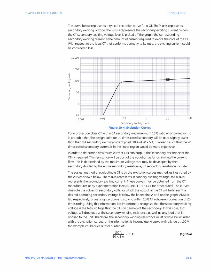
CHAPTER 10: MISCELLANEOUS CT ISOLATION
MM3 MOTOR MANAGER 3 – INSTRUCTION MANUAL 10–5
The curve below represents a typical excitation curve for a CT. The Y-axis represents secondary exciting voltage; the X-axis represents the secondary exciting current. When the CT secondary exciting voltage level is picked off the graph, the corresponding secondary exciting current is the amount of current required to excite the core of the CT. With respect to the ideal CT that conforms perfectly to its ratio, the exciting current could be considered loss.
Figure 10-4: Excitation Curves
For a protection class CT with a 5A secondary and maximum 10% ratio error correction, it is probable that the design point for 20 times rated secondary will be at or slightly lower than the 10 A secondary exciting current point (10% of 20 × 5 A). To design such that the 20 times rated secondary current is in the linear region would be more expensive.
In order to determine how much current CTs can output, the secondary resistance of the CTs is required. This resistance will be part of the equation as far as limiting the current flow. This is determined by the maximum voltage that may be developed by the CT secondary divided by the entire secondary resistance, CT secondary resistance included.
The easiest method of evaluating a CT is by the excitation curves method, as illustrated by the curves shown below. The Y-axis represents secondary exciting voltage; the X-axis represents the secondary exciting current. These curves may be obtained from the CT manufacturer, or by experimentation (see ANSI/IEEE C57.13.1 for procedures). The curves illustrate the values of secondary volts for which the output of the CT will be linear. The desired operating secondary voltage is below the kneepoint (A or B on the graph (ANSI or IEC respectively) or just slightly above it , staying within 10% CT ratio error correction at 20 times rating. Using this information, it is important to recognize that the secondary exciting voltage is the total voltage that the CT can develop at the secondary. In this case, that voltage will drop across the secondary winding resistance as well as any load that is applied to the unit. Therefore, the secondary winding resistance must always be included with the excitation curves, or the information is incomplete. A curve with a knee at 100 V for example could drive a total burden of:
(EQ 10.4)
Secondary exciting amps0.001 0.01 0.1 1 10 100
Seco
ndar
y ex
citin
g vo
lts
0.1
1
10
100
1000
10 000
100 V20 5 A×--------------------- 1 Ω=
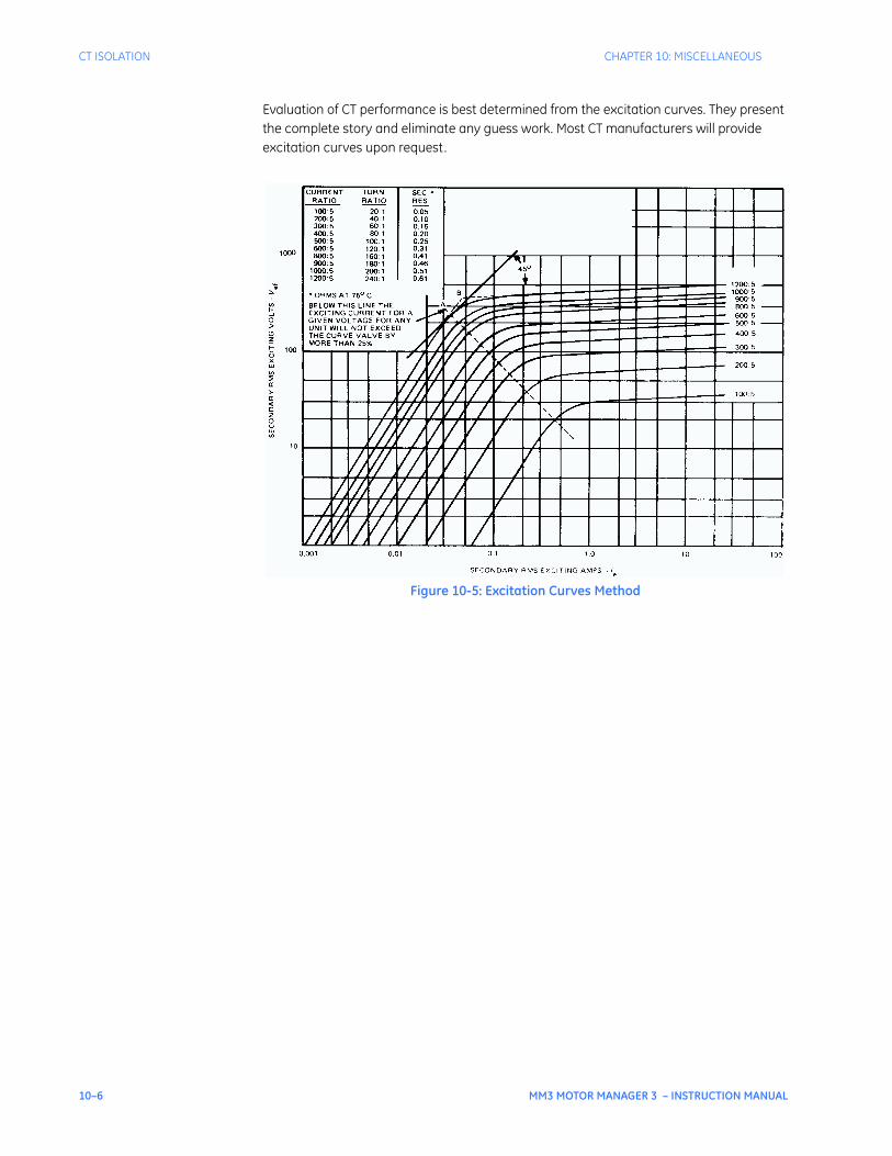
10–6 MM3 MOTOR MANAGER 3 – INSTRUCTION MANUAL
CT ISOLATION CHAPTER 10: MISCELLANEOUS
Evaluation of CT performance is best determined from the excitation curves. They present the complete story and eliminate any guess work. Most CT manufacturers will provide excitation curves upon request.
Figure 10-5: Excitation Curves Method

CHAPTER 10: MISCELLANEOUS MM3 MOTOR MANAGER 3 FAQ
MM3 MOTOR MANAGER 3 – INSTRUCTION MANUAL 10–7
10.3 MM3 Motor Manager 3 FAQ
10.3.1 Frequently Asked Questions
Listed below are some of the more frequently asked questions by users of the MM3 Motor Manager 3. The list includes questions asked by consultants before the MM3 Motor Manager 3 has even been specified to the end user and after the MM3 Motor Manager 3 is installed and controlling a motor.
Does the MM3 Motor Manager 3 support ladder logic as in a PLC?
No. The MM3 Motor Manager 3 switch inputs do not allow total programmability as in PLCs; however, it does have a range of over 30 different dedicated functions that can be assigned for typical applications. These functions come complete with built in timers if necessary for that particular function. For example: Auto Permissive and Auto Start for PLC hard wired control, Two Wire Control for PLC starts or jogging, Process Interlocks with starting and running override timers for pressure and flow monitoring. All the programmable switch inputs may be configured as normally open or normally closed.
Does the MM3 Motor Manager 3 have any hot winding protection?
Yes. The MM3 Motor Manager 3 has a single thermistor input to protect the motor against hot windings. These thermistors are typically wound into stator windings of the motor when manufactured and can be Positive Temperature Coefficient (PTC) of Negative Temperature Coefficient (NTC).
After wiring the MM3 Motor Manager 3 into the control circuit, it remains UNAVAILABLE for starts. What does this mean?
Three conditions can cause the MM3 Motor Manager 3 to remain UNAVAILABLE for starts”
1. The MM3 Motor Manager 3 has tripped on a trip condition
2. The STOP switch input (terminal 11) is not energized.
3. If a Process Interlock function is assigned to one of the programmable switch inputs and the startup override is set to 0 seconds, the MM3 Motor Manager 3 will remain UNAVAILABLE until that switch input is energized.
When a start is attempted, the motor starts for a second then shuts off. The MM3 Motor Manager 3 displays an OPEN CONTROL CIRCUIT alarm. What is the problem?
The MM3 Motor Manager 3 must see feedback from the Contactor A and, if used, Contactor B within 1 second of the MM3 Motor Manager 3 closing the contactor or the MM3 Motor Manager 3 will stop the motor as it assumes that there is a problem in the circuitry for the motor contactor coil. The feedback from the contactors go to the status inputs (terminals 15 and 16) of the MM3 Motor Manager 3.
This condition will result in the toggling of the motor contactor when the MM3 Motor Manager 3 is in the two-wire mode as there can be a constant start signal from the two wire device. Use the open control circuit trip feature to prevent the toggling of the motor contactor.
After connecting the MM3 Motor Manager 3 through an interface device to a PLC network, communications to the MM3 Motor Manager 3 cannot be established. What is the problem?
Verify the following:
1. The master communicating with Modbus® RTU protocol.
NOTE

10–8 MM3 MOTOR MANAGER 3 – INSTRUCTION MANUAL
MM3 MOTOR MANAGER 3 FAQ CHAPTER 10: MISCELLANEOUS
2. Wiring between interface device and MM3 Motor Manager 3.
3. MM3 Motor Manager 3 communications address.
4. Master polling address.
5. MM3 Motor Manager 3 baud rate.
6. Master baud rate.
7. MM3 Motor Manager 3 parity setpoint.
8. Master parity settings.
If the problem persists, call GE Multilin for technical support.
Can the MM3 Motor Manager 3 interface with an external analog device?
Yes. The MM3 Motor Manager 3 has a single analog input that can be used to monitor an external transducer. Alarm and trip setpoints can be configured to warn the user or shut down the motor.
Can the MM3 Motor Manager 3 be used on medium voltage motors?
No. The MM3 Motor Manager 3 was designed specifically for the low voltage market (600 V or less). The protection features offered in the MM3 Motor Manager 3 are typically not advanced enough for larger, more expensive motors. The power measuring will only accommodate 600 V systems.
Can the START keys on the faceplate of the MM3 Motor Manager 3 be disabled?
Yes. One of the programmable switch inputs can be configured to REMOTE PERMISSIVE and a jumper placed from Switch Common to permanently energize that switch input. This will allow starts from the switch inputs of the MM3 Motor Manager 3 only, when in the MANUAL mode.
CHAPTER 10: MISCELLANEOUS INSTALLATION CHECKLIST
MM3 MOTOR MANAGER 3 – INSTRUCTION MANUAL 10–9
10.4 Installation checklist
10.4.1 Overview For proper and reliable operation of the GE Multilin MM3 Motor Manager 3 Motor Manager 3, it is imperative that the steps, recommendations and practices listed below be adhered to at all times. This installation checklist has been compiled as a result of years of trouble free operation by a variety of GE Multilin products.
10.4.2 MM3 Motor Manager 3 Grounding
Users are requested to ground terminals 21, 48 (safety ground) and 22 (filter ground) directly to the ground bus using a heavy gauge wire or braided cable. Terminals 21, 22, and 48 will accept up to #12 AWG wire. These terminals must be grounded for proper filtering of noise, and protection against transient conditions.
10.4.3 Grounding of Phase and Ground CTs
All external phase CT and ground CT secondary windings must be grounded to the ground bus to keep the potential difference to a minimum. If the CT secondary windings are not grounded, capacitive coupling could allow the CT secondary voltage to float up to the voltage of the mains. This is a serious safety hazard.
Terminal 20 of the external ground CT is internally grounded therefore do not ground terminal 19 since the ground CT signal would then be shunted.
It is also recommended that, in addition to the solid grounding of the ground CT described above, a shielded twisted pair cable be employed when using the GE Multilin 50:0.025 ground CT. The reasoning behind this recommendation is that the 50:0.025 ground CTs are typically used on high resistance grounded systems where the fault currents are limited to less than 200 A. The alarm and trip levels on these systems are usually between 0.5 A and 15.0 A. This equates to a secondary current of 0.25 to 7.5 mA. Due to the very low levels that must be monitored by the MM3 Motor Manager 3, any noise picked up by these secondary wires must be kept to a minimum.
10.4.4 RS485 Com-munications Port
The MM3 Motor Manager 3 interfaces with PCs, PLCs, and DCSs using the Modicon Modbus RTU protocol. The MM3 Motor Manager 3 supports Modbus function codes 01, 03, 04, 05, 06, 07, 08, and 16. The communications port is a very important part of the MM3 Motor Manager 3s process and control applications. The port allows reading and writing of data as well as full control to start and stop the motor from a remote location. For these reasons, proper wiring practices are critical.
• A shielded, twisted pair cable, such as 24 gauge Belden 9841 (120 Ω characteristic impedance) or equivalent, MUST be used for the communications link. The cable should be routed away from all power carrying cables, such as the motor mains, power supply wiring, CT wiring and noisy contactors or breakers.
When using the GE Multilin 232/485 converter box at the master, GE Multilin recommends placing no more than 32 GE devices on the same data link which should be of no greater length than 4000 ft . The devices on the data link should be daisy chained for reliable operation. Star or stub connections are not recommended. If more than 32 devices are required to go onto the data link, or the distance must be
NOTE

10–10 MM3 MOTOR MANAGER 3 – INSTRUCTION MANUAL
INSTALLATION CHECKLIST CHAPTER 10: MISCELLANEOUS
greater than 4000 feet, consult the EIA 485 standard for more details on specific calculations. Another way to increase the number of units on the data link or the transmission length is to utilize a RS485 repeater.
• The shields of the cable should be daisy chained to all of the MM3 Motor Manager 3 serial commons (terminal 27) and grounded at the master only. This provides a common reference for all of the devices on the data link, as well as, grounding the data link without creating the potential for ground loops. The potential difference between the MM3 Motor Manager 3 safety ground (terminals 21 and 48) and the MM3 Motor Manager 3 serial common (terminal 27) should not exceed 36 V.
• A terminating network consisting of a 120 Ω / 0.25 W resistor in series with a 1 nF /50 V general purpose mono ceramic or equivalent capacitor must be placed across
the positive and negative terminals at both ends of the data link (terminals 39 and 40 on the MM3 Motor Manager 3). This is to provide the 200 mV separation between the positive and negative terminals of the device, as well as to eliminate any reflected signals and ringing.
10.4.5 Switch Inputs The MM3 Motor Manager 3 has 16 switch inputs that operate on 120 V AC when the control voltage switch is set to 120 V AC and 240 V AC when the control voltage switch is set 240 V AC.
It is recommended that the switch terminals are activated from the same source as is connected to Terminals 23 and 24. The common of the switch inputs is though terminal 23.
An external source can be used to supply the circuitry into the MM3 Motor Manager 3 switch inputs providing that the external source is in phase with the control voltage of the MM3 Motor Manager 3. The MM3 Motor Manager 3 switches the inputs on and off internally, to minimize power consumption, at a frequency determined by the control voltage. If the external source is not in phase with the control voltage to the MM3 Motor Manager 3, the timing will be off which could cause errors when reading the switch inputs. If an external source is used to supply the control signals to the MM3 Motor Manager 3 switch inputs, the source should be fused to protect against fault conditions in the circuitry.
10.4.6 Thermistor and Analog Inputs
Due to the small voltage levels coming into the MM3 Motor Manager 3 from the thermistor and external analog device, shielded cable is recommended to minimize any noise that may be picked up. These wires should be routed away from any power carrying cables.
10.4.7 Stop Switch Input
The STOP switch input on the MM3 Motor Manager 3 must be energized before the MM3 Motor Manager 3 is available to perform a start. If the contactor is being energized and de-energized externally to the MM3 Motor Manager 3, this terminal will need a jumper from terminal 24 before the MM3 Motor Manager 3 will seal in contactor A.
10.4.8 Contactor Status Feedback
The MM3 Motor Manager 3 must see feedback from contactor A and contactor B auxiliary contacts into the applicable status switch inputs (terminals 15 and 16) within 1 second of closing the contactor. If this feedback is not received, the MM3 Motor Manager 3 will open the contactor instead of sealing it in, and will alarm with an open control circuit.
NOTE
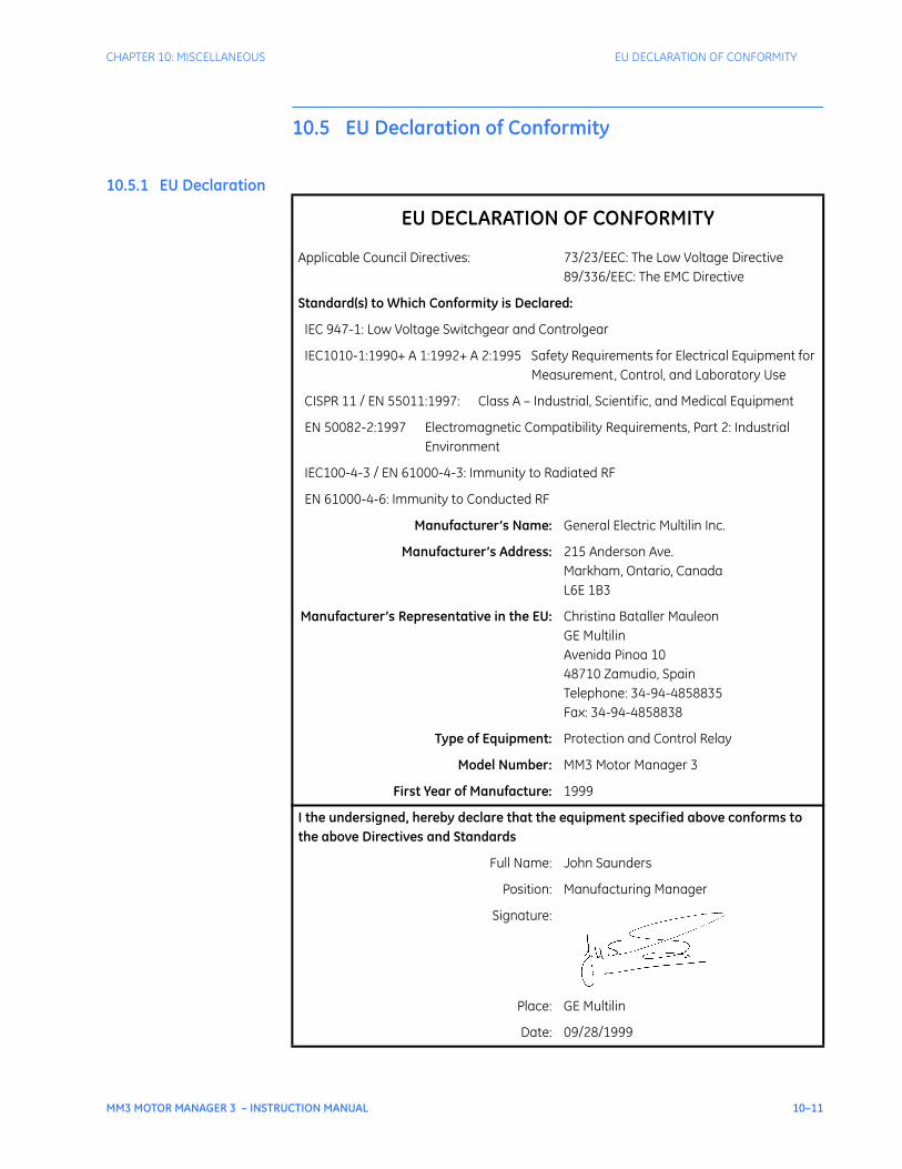
CHAPTER 10: MISCELLANEOUS EU DECLARATION OF CONFORMITY
MM3 MOTOR MANAGER 3 – INSTRUCTION MANUAL 10–11
10.5 EU Declaration of Conformity
10.5.1 EU Declaration
EU DECLARATION OF CONFORMITY
Applicable Council Directives: 73/23/EEC: The Low Voltage Directive89/336/EEC: The EMC Directive
Standard(s) to Which Conformity is Declared:
IEC 947-1: Low Voltage Switchgear and Controlgear
IEC1010-1:1990+ A 1:1992+ A 2:1995 Safety Requirements for Electrical Equipment for Measurement, Control, and Laboratory Use
CISPR 11 / EN 55011:1997: Class A – Industrial, Scientific, and Medical Equipment
EN 50082-2:1997 Electromagnetic Compatibility Requirements, Part 2: Industrial Environment
IEC100-4-3 / EN 61000-4-3: Immunity to Radiated RF
EN 61000-4-6: Immunity to Conducted RF
Manufacturer’s Name: General Electric Multilin Inc.
Manufacturer’s Address: 215 Anderson Ave.Markham, Ontario, CanadaL6E 1B3
Manufacturer’s Representative in the EU: Christina Bataller MauleonGE MultilinAvenida Pinoa 1048710 Zamudio, SpainTelephone: 34-94-4858835Fax: 34-94-4858838
Type of Equipment: Protection and Control Relay
Model Number: MM3 Motor Manager 3
First Year of Manufacture: 1999
I the undersigned, hereby declare that the equipment specified above conforms to the above Directives and Standards
Full Name: John Saunders
Position: Manufacturing Manager
Signature:
Place: GE Multilin
Date: 09/28/1999
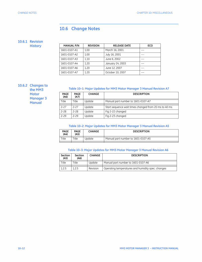
10–12 MM3 MOTOR MANAGER 3 – INSTRUCTION MANUAL
CHANGE NOTES CHAPTER 10: MISCELLANEOUS
10.6 Change Notes
10.6.1 Revision History
10.6.2 Changes to the MM3 Motor Manager 3 Manual
MANUAL P/N REVISION RELEASE DATE ECO
1601-0107-A1 1.00 March 16, 2001 ---
1601-0107-A2 1.00 July 16, 2001 ---
1601-0107-A3 1.10 June 6, 2002 ---
1601-0107-A4 1.20 January 24, 2003 ---
1601-0107-A6 1.20 June 12, 2007 ---
1601-0107-A7 1.20 October 10, 2007 ---
Table 10–1: Major Updates for MM3 Motor Manager 3 Manual Revision A7
PAGE (A6)
PAGE (A7)
CHANGE DESCRIPTION
Title Title Update Manual part number to 1601-0107-A7
2-27 2-27 Update Start sequence wait times changed from 20 ms to 40 ms
2-28 2-28 Update Fig 2-22 changed
2-29 2-29 Update Fig 2-23 changed
Table 10–2: Major Updates for MM3 Motor Manager 3 Manual Revision A5
PAGE (A4)
PAGE (A5)
CHANGE DESCRIPTION
Title Title Update Manual part number to 1601-0107-A5
Table 10–3: Major Updates for MM3 Motor Manager 3 Manual Revision A6
Section (A5)
Section (A6)
CHANGE DESCRIPTION
Title Title Update Manual part number to 1601-0107-A6
1.2.5 1.2.5 Revision Operating temperatures and humidity spec. changes

CHAPTER 10: MISCELLANEOUS GE MULTILIN WARRANTY
MM3 MOTOR MANAGER 3 – INSTRUCTION MANUAL 10–13
10.7 GE Multilin Warranty
10.7.1 Warranty Statement
General Electric Multilin (GE Multilin) warrants each device it manufactures to be free from defects in material and workmanship under normal use and service for a period of 24 months from date of shipment from factory.
In the event of a failure covered by warranty, GE Multilin will undertake to repair or replace the device providing the warrantor determined that it is defective and it is returned with all transportation charges prepaid to an authorized service centre or the factory. Repairs or replacement under warranty will be made without charge.
Warranty shall not apply to any device which has been subject to misuse, negligence, accident, incorrect installation or use not in accordance with instructions nor any unit that has been altered outside a GE Multilin authorized factory outlet.
GE Multilin is not liable for special, indirect or consequential damages or for loss of profit or for expenses sustained as a result of a device malfunction, incorrect application or adjustment.
For complete text of Warranty (including limitations and disclaimers), refer to GE Multilin Standard Conditions of Sale.

10–14 MM3 MOTOR MANAGER 3 – INSTRUCTION MANUAL
GE MULTILIN WARRANTY CHAPTER 10: MISCELLANEOUS
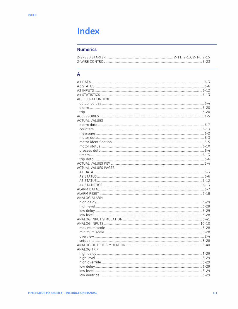
INDEX
MM3 MOTOR MANAGER 3 – INSTRUCTION MANUAL I–1
IndexIndex
Numerics
2-SPEED STARTER ............................................................................. 2-11, 2-13, 2-14, 2-152-WIRE CONTROL ............................................................................................................... 5-23
A
A1 DATA ........................................................................................................................ .......... 6-3A2 STATUS ...................................................................................................................... ....... 6-6A3 INPUTS ...................................................................................................................... ...... 6-12A4 STATISTICS .................................................................................................................. ... 6-13ACCELERATION TIME
actual values .................................................................................................................. .... 6-4alarm .......................................................................................................................... ........ 5-20trip ........................................................................................................................... ........... 5-20
ACCESSORIES .................................................................................................................... .... 1-5ACTUAL VALUES
alarm data ..................................................................................................................... ..... 6-7counters ....................................................................................................................... ..... 6-13messages ....................................................................................................................... ..... 6-2motor data ..................................................................................................................... ..... 6-3motor identification ......................................................................................................... 5-5motor status ................................................................................................................... .. 6-10process data ................................................................................................................... ... 6-4timers ......................................................................................................................... ........ 6-13trip data ...................................................................................................................... ........ 6-6
ACTUAL VALUES KEY ........................................................................................................... 3-4ACTUAL VALUES PAGES
A1 DATA ........................................................................................................................ ....... 6-3A2 STATUS ...................................................................................................................... ..... 6-6A3 STATUS ...................................................................................................................... ... 6-12A4 STATISTICS .................................................................................................................. 6-13
ALARM DATA ..................................................................................................................... ..... 6-7ALARM RESET .................................................................................................................... .. 5-18ANALOG ALARM
high delay ..................................................................................................................... .... 5-29high level ..................................................................................................................... ...... 5-29low delay ...................................................................................................................... ..... 5-29low level ...................................................................................................................... ...... 5-28
ANALOG INPUT SIMULATION ........................................................................................... 5-41ANALOG INPUTS ...............................................................................................................10-10
maximum scale ............................................................................................................... 5-28minimum scale ................................................................................................................ 5-28overview ....................................................................................................................... ....... 2-4setpoints ...................................................................................................................... ..... 5-28
ANALOG OUTPUT SIMULATION ....................................................................................... 5-40ANALOG TRIP
high delay ..................................................................................................................... .... 5-29high level ..................................................................................................................... ...... 5-29high override .................................................................................................................. .. 5-29low delay ...................................................................................................................... ..... 5-29low level ...................................................................................................................... ...... 5-29low override ................................................................................................................... .. 5-29
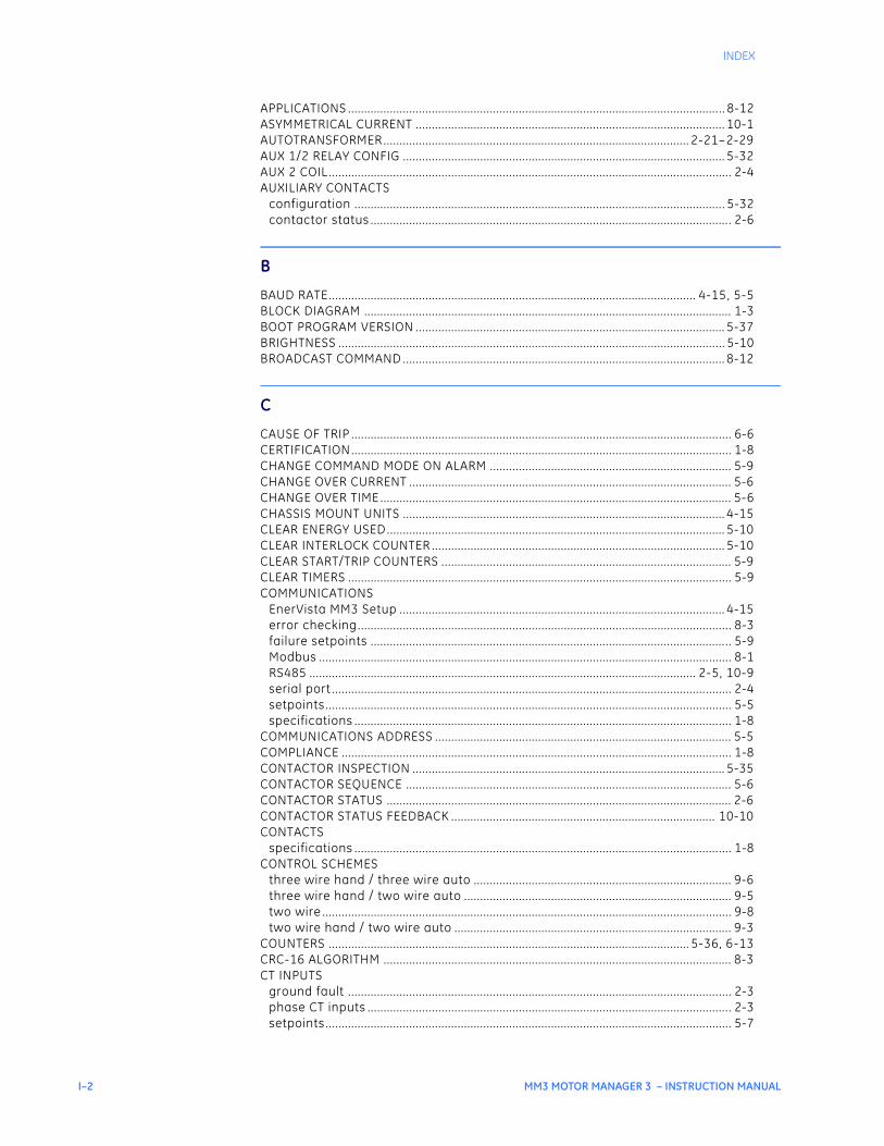
I–2 MM3 MOTOR MANAGER 3 – INSTRUCTION MANUAL
INDEX
APPLICATIONS ................................................................................................................... .. 8-12ASYMMETRICAL CURRENT ................................................................................................ 10-1AUTOTRANSFORMER ............................................................................................... 2-21–2-29AUX 1/2 RELAY CONFIG .................................................................................................... 5-32AUX 2 COIL ..................................................................................................................... ........ 2-4AUXILIARY CONTACTS
configuration .................................................................................................................. . 5-32contactor status ............................................................................................................... . 2-6
B
BAUD RATE .................................................................................................................. 4-15, 5-5BLOCK DIAGRAM .................................................................................................................. 1-3BOOT PROGRAM VERSION ................................................................................................ 5-37BRIGHTNESS ..................................................................................................................... ... 5-10BROADCAST COMMAND .................................................................................................... 8-12
C
CAUSE OF TRIP .................................................................................................................. .... 6-6CERTIFICATION .................................................................................................................. .... 1-8CHANGE COMMAND MODE ON ALARM ........................................................................... 5-9CHANGE OVER CURRENT .................................................................................................... 5-6CHANGE OVER TIME ............................................................................................................. 5-6CHASSIS MOUNT UNITS .................................................................................................... 4-15CLEAR ENERGY USED ......................................................................................................... 5-10CLEAR INTERLOCK COUNTER ........................................................................................... 5-10CLEAR START/TRIP COUNTERS .......................................................................................... 5-9CLEAR TIMERS ................................................................................................................... .... 5-9COMMUNICATIONS
EnerVista MM3 Setup ..................................................................................................... 4-15error checking................................................................................................................. ... 8-3failure setpoints .............................................................................................................. .. 5-9Modbus ......................................................................................................................... ....... 8-1RS485 ........................................................................................................................ 2-5, 10-9serial port .................................................................................................................... ........ 2-4setpoints ...................................................................................................................... ........ 5-5specifications ................................................................................................................. .... 1-8
COMMUNICATIONS ADDRESS ............................................................................................ 5-5COMPLIANCE ..................................................................................................................... .... 1-8CONTACTOR INSPECTION ................................................................................................. 5-35CONTACTOR SEQUENCE ..................................................................................................... 5-6CONTACTOR STATUS ........................................................................................................... 2-6CONTACTOR STATUS FEEDBACK .................................................................................. 10-10CONTACTS
specifications ................................................................................................................. .... 1-8CONTROL SCHEMES
three wire hand / three wire auto ................................................................................ 9-6three wire hand / two wire auto ................................................................................... 9-5two wire ....................................................................................................................... ........ 9-8two wire hand / two wire auto ...................................................................................... 9-3
COUNTERS ................................................................................................................ 5-36, 6-13CRC-16 ALGORITHM ............................................................................................................ 8-3CT INPUTS
ground fault ................................................................................................................... .... 2-3phase CT inputs ................................................................................................................ . 2-3setpoints ...................................................................................................................... ........ 5-7
INDEX
MM3 MOTOR MANAGER 3 – INSTRUCTION MANUAL I–3
CT ISOLATION ................................................................................................................... ... 10-4CT SATURATION .................................................................................................................. 10-4CT SIZE ........................................................................................................................ .......... 10-4CT/VT INPUTS ................................................................................................................... ..... 5-7CTs
excitation curves ............................................................................................................ 10-5isolation ...................................................................................................................... ....... 10-4saturation ..................................................................................................................... .... 10-4size ........................................................................................................................... ........... 10-4
CURRENT SIMULATION ...................................................................................................... 5-39CURRENT-VOLTAGE PHASE DIFFERENCE ...................................................................... 10-1
D
DATA FORMATSframe format ................................................................................................................... ... 8-2modbus ......................................................................................................................... ..... 8-43packet format .................................................................................................................. .. 8-2
DATA PACKET SYNCHRONIZATION ................................................................................... 8-4DATA RATE ...................................................................................................................... ....... 8-2DEFAULT MESSAGE SELECTION......................................................................................... 6-2DEFAULT MESSAGES
preferences .................................................................................................................... .. 5-10selecting ...................................................................................................................... ........ 6-2
DESCRIPTION .................................................................................................................... ..... 1-1DIELECTRIC STRENGTH TESTING ....................................................................................... 2-6DIMENSIONS ..................................................................................................................... ..... 2-1DO’S AND DONT’S .............................................................................................................. 10-9DUTY/STANDBY STARTER ...................................................................................... 2-34, 2-36
E
ELECTRICAL INTERFACE ...................................................................................................... 8-1ENERGY USED ............................................................................................................ 5-10, 6-4ENERVISTA
communications.............................................................................................................. 4-15configuring .................................................................................................................... ..... 4-5setpoints ................................................................................................................ 4-10, 4-11
ENVIRONMENT .................................................................................................................... .. 1-8ERROR CHECKING ................................................................................................................ 8-3ERROR RESPONSES ............................................................................................................ 8-11EU DECLARATION OF CONFORMITY .............................................................................10-11EXTERNAL CONNECTIONS .................................................................................................. 2-3
F
FACEPLATE FUNCTIONS ...................................................................................................... 3-1FACEPLATE STOP ................................................................................................................ 5-27FACTORY DATA................................................................................................................... . 5-37FACTORY SERVICE DATA ................................................................................................... 5-37FAULT MODE..................................................................................................................... ..... 5-9FEATURES ....................................................................................................................... ........ 1-1FIELD STOP ..................................................................................................................... ..... 5-27FIRMWARE IDENTIFICATION ............................................................................................ 5-37FREQUENCY ...................................................................................................................... ..... 5-7FRONT PANEL .................................................................................................................... .... 3-2
I–4 MM3 MOTOR MANAGER 3 – INSTRUCTION MANUAL
INDEX
FULL LOAD CURRENT ........................................................................................................ 5-11FULL VOLTAGE REVERSING STARTER .................................................................... 2-9, 2-10FULL-VOLTAGE NON-REVERSING STARTER ........................................................... 2-7, 2-8FUNCTIONAL BLOCK DIAGRAM ......................................................................................... 1-3FUNCTIONAL TESTS ............................................................................................................. 7-3FUSE RATING .................................................................................................................... ..... 1-9
G
GE OVERLOAD CURVES ..................................................................................................... 5-13GENERAL INPUT/OUTPUT OVERVIEW............................................................................... 2-3GROUND CURRENT .............................................................................................................. 6-4GROUND FAULT ALARM .................................................................................................... 5-16GROUND FAULT CT INPUT ......................................................................................... 2-3, 5-7GROUND FAULT CURRENT FUNCTIONS ........................................................................... 7-5GROUND FAULT TRIP ......................................................................................................... 5-16GROUND SURGE ................................................................................................................... 2-3GROUNDING
phase and ground CTs ................................................................................................... 10-9
H
HARDWARE DESCRIPTION .................................................................................................. 3-6HARDWARE REVISION ....................................................................................................... 5-37HIGH SPEED START BLOCK ................................................................................................. 5-6HOT/COLD CURVE RATIO .................................................................................................. 5-11
I
IED SETUP ...................................................................................................................... ........ 4-2INDICATOR LEDs ................................................................................................................. .. 3-2INPUT CONTACTS STATUS ................................................................................................ 6-12INPUT FUNCTIONS ............................................................................................................... 7-5INPUTS
analog ..................................................................................................................... 2-4, 10-10contact status ................................................................................................................. . 6-12CT ............................................................................................................................. ............. 5-7ground fault CT ................................................................................................................ .. 2-3overview ....................................................................................................................... ....... 2-3phase CT ....................................................................................................................... ....... 2-3programmable ................................................................................................................. 5-22programmable switch ...................................................................................................... 2-5specifications ................................................................................................................. .... 1-7start A ........................................................................................................................ .......... 2-5start B ........................................................................................................................ .......... 2-5stop ........................................................................................................................... ............ 2-5stop switch .................................................................................................................... 10-10switch ...................................................................................................................... 2-5, 10-10thermistor .............................................................................................................. 2-3, 10-10VT ............................................................................................................................. ............. 5-7
INPUTS, ANALOGsetpoints ...................................................................................................................... ...... 5-28specifications ................................................................................................................. .... 1-7
INSTALLATION ................................................................................................................... .... 1-9INTERLOCK COUNTER
clearing ....................................................................................................................... ....... 5-10
INDEX
MM3 MOTOR MANAGER 3 – INSTRUCTION MANUAL I–5
INTERLOCK INPUTS 1-10 .................................................................................................. 5-22INTERLOCK NAMES ............................................................................................................ 5-27INTERNAL FAULT TRIP ......................................................................................................... 5-9INVERTER STARTER ................................................................................................. 2-20, 2-21
J
K
KEYPAD ......................................................................................................................... .......... 3-4
L
LAST STARTING CURRENT .................................................................................................. 6-4LEDs
indicator ...................................................................................................................... ........ 3-2test ........................................................................................................................... ........... 5-38
LOAD INCREASE ALARM .................................................................................................... 5-19LOAD PROTECTION............................................................................................................. 5-19LOCAL ISOLATOR ....................................................................................................... 2-6, 5-22
M
MAXIMUM MOTOR STOPPED TIME .................................................................................. 5-35MEMORY MAP ..................................................................................................................... . 8-16MESSAGE DISPLAY ............................................................................................................... 3-1MESSAGE LEFT/RIGHT KEYS ............................................................................................... 3-5MESSAGE UP/DOWN KEYS ................................................................................................. 3-5MESSAGES
actual values abbreviations ........................................................................................... 6-2programmable ................................................................................................................... 6-5setpoints ...................................................................................................................... ....... 5-4
MINIMIZE RESET TIME ........................................................................................................ 5-17MMII
supported functions ......................................................................................................... 8-5MOD NUMBER ..................................................................................................................... 5-37MODBUS
function code 01 ............................................................................................................... 8-5function code 03 ............................................................................................................... 8-6function code 04 ............................................................................................................... 8-6function code 05 ............................................................................................................... 8-7function code 06 ............................................................................................................... 8-8function code 07 ............................................................................................................... 8-8function code 08 ............................................................................................................. 8-10function code 10 ............................................................................................................. 8-10memory map .................................................................................................................... 8-16
MODEL IDENTIFICATION ................................................................................................... 5-37MODEL NUMBERS ................................................................................................................. 1-5MOTOR DATA ..................................................................................................................... .... 6-3MOTOR GREASING INTERVAL ........................................................................................... 5-35MOTOR IDENTIFICATION ..................................................................................................... 5-5MOTOR LOAD..................................................................................................................... .... 6-4MOTOR NAME ..................................................................................................................... ... 5-5MOTOR PROTECTION
ground fault ................................................................................................................... .. 5-16
I–6 MM3 MOTOR MANAGER 3 – INSTRUCTION MANUAL
INDEX
options ........................................................................................................................ ....... 5-17thermal ........................................................................................................................ ...... 5-11
MOTOR RATING ................................................................................................................... .. 5-5MOTOR START THREE PHASE CURRENT ........................................................................ 10-2MOTOR STATUS .......................................................................................................... 6-3, 6-10MOUNTING ....................................................................................................................... ...... 2-1
N
NEMA OVERLOAD CURVES .................................................................................... 5-14, 5-15NOMINAL FREQUENCY ........................................................................................................ 5-7
O
OPEN CONTROL CIRCUIT TRIP ......................................................................................... 5-17OPTIONS ........................................................................................................................ ......... 1-2ORDER INFORMATION .............................................................................................. 1-5, 5-37OUTPUT RELAYS .................................................................................................................. .. 2-4OUTPUTS
analog ......................................................................................................................... ......... 2-4overview ....................................................................................................................... ....... 2-3specifications ................................................................................................................. .... 1-7
OVERLOAD CURVE NUMBER ............................................................................................ 5-11OVERLOAD CURVES
GE Multilin .................................................................................................................... ..... 5-13NEMA ....................................................................................................................... 5-14, 5-15setpoints ...................................................................................................................... ...... 5-11
OVERLOAD PICKUP LEVEL ................................................................................................ 5-11OVERLOAD TRIP RESET ...................................................................................................... 5-17OVERVIEW ....................................................................................................................... ....... 1-1OVERVOLTAGE.................................................................................................................... . 5-21
P
PARITY ......................................................................................................................... . 4-15, 5-5PART WINDING STARTER .................................................................................................. 2-29PHASE CT INPUTS ................................................................................................................ . 2-3PHASE CT PRIMARY AMPS................................................................................................... 5-7PHASE CURRENT FUNCTIONS ............................................................................................ 7-3PHASE CURRENTS................................................................................................................. 6-4PHASE UNBALANCE ............................................................................................................. 6-4PHASE UNBALANCE ALARM ............................................................................................. 5-17PLANT CONDITION ............................................................................................................. 5-35POWER FAIL TEST ................................................................................................................ . 7-6POWER SUPPLY ............................................................................................................ 1-6, 2-3PREFERENCES .................................................................................................................... .. 5-10PRESET COUNTERS AND TIMERS ..................................................................................... 5-36PRIMARY INJECTION TESTING ........................................................................................... 7-1PRIMARY RESISTANCE STARTER ........................................................................... 2-18, 2-19PROCESS DATA ................................................................................................................... ... 6-4PROCESS STOP ................................................................................................................... . 5-27PRODUCT FIRMWARE IDENTIFICATION.......................................................................... 5-37PRODUCT MODEL IDENTIFICATION ................................................................................ 5-37PRODUCTION TEST ............................................................................................................... 1-8PROGRAMMABLE INPUTS .................................................................................................. 5-22PROGRAMMABLE MESSAGE ................................................................................................ 6-5
INDEX
MM3 MOTOR MANAGER 3 – INSTRUCTION MANUAL I–7
PROGRAMMABLE SWITCH INPUTS .................................................................................... 2-5
Q
QUESTIONS AND ANSWERS ............................................................................................. 10-7
R
RAMP DOWN TIME................................................................................................................ 5-6RAMP UP TIME ................................................................................................................... .... 5-6RESET ALARMS ................................................................................................................... . 5-18RESET KEY ...................................................................................................................... ........ 3-5RESET LOCKOUT ................................................................................................................. 5-18RS485
communications port ..................................................................................................... 10-9termination .................................................................................................................... ..... 2-5
RUNNING TIME ................................................................................................................... . 6-13
S
S1 CONFIGURATION............................................................................................................. 5-5S2 PROTECTION .................................................................................................................. 5-11S3 PROCESS ..................................................................................................................... .... 5-22S4 CONTROL ..................................................................................................................... ... 5-31S5 MONITORING ................................................................................................................. 5-35S6 FACTORY DATA .............................................................................................................. 5-37S7 TESTING ..................................................................................................................... ..... 5-38SECONDARY INJECTION TESTING .............................................................................7-1, 7-2SELECTION GUIDE ................................................................................................................ 1-5SERIAL COMMS FAILURE ..................................................................................................... 5-9SERIAL COMMUNICATION PORT ........................................................................................ 2-4SERIAL NUMBER.................................................................................................................. 5-37SERIAL PERMISSIVE ............................................................................................................ 5-26SERVICE DATA ................................................................................................................... .. 5-37SETPOINT MESSAGES
abbreviations .................................................................................................................. ... 5-4SETPOINTS
analog input ................................................................................................................... .. 5-28analog input simulation ................................................................................................ 5-41analog output simulation ............................................................................................. 5-40auxiliary relay configuration ........................................................................................ 5-32communications................................................................................................................ 5-5CT/VT inputs ................................................................................................................... .... 5-7current simulation .......................................................................................................... 5-39entering via software ..................................................................................................... 4-11factory service data ....................................................................................................... 5-37fault mode ..................................................................................................................... ..... 5-9input contacts status ..................................................................................................... 6-12interlock names ............................................................................................................... 5-27load protection ................................................................................................................ 5-19loading via software ...................................................................................................... 4-10model identification ....................................................................................................... 5-37motor protection – ground fault ................................................................................. 5-16motor protection – options .......................................................................................... 5-17motor protection – thermal .......................................................................................... 5-11plant condition ................................................................................................................ 5-35
I–8 MM3 MOTOR MANAGER 3 – INSTRUCTION MANUAL
INDEX
preferences .................................................................................................................... .. 5-10preset counters and timers .......................................................................................... 5-36product firmware identification .................................................................................. 5-37programmable inputs .................................................................................................... 5-22programmable message ................................................................................................. 6-5starter ........................................................................................................................ .......... 5-6stop configuration .......................................................................................................... 5-27switch inputs simulation ............................................................................................... 5-41test configuration ........................................................................................................... 5-38test relays and LEDs ....................................................................................................... 5-38thermistor simulation .................................................................................................... 5-42under/overvoltage protection ..................................................................................... 5-21undervoltage autorestart ............................................................................................. 5-31
SETPOINTS KEY .................................................................................................................. ... 3-4SETPOINTS PAGES
S1 CONFIGURATION .......................................................................................................... 5-5S2 PROTECTION................................................................................................................ 5-11S3 PROCESS ..................................................................................................................... . 5-22S4 CONTROL ..................................................................................................................... 5-31S5 MONITORING ............................................................................................................... 5-35S6 FACTORY DATA ........................................................................................................... 5-37S7 TESTING..................................................................................................................... ... 5-38
SINGLE-LINE DIAGRAM ....................................................................................................... 1-3SLIP RING STARTER ................................................................................................. 2-16, 2-17SOFT STARTER .......................................................................................................... 2-36, 2-38SPECIFICATIONS ................................................................................................................. .. 1-6STAGE ONE SHORTING TIME .............................................................................................. 5-6STALLED ROTOR ......................................................................................................... 1-6, 5-19STANDARD FEATURES ......................................................................................................... 1-1START A ........................................................................................................................ .......... 2-5START A KEY .................................................................................................................... ...... 3-5START B ........................................................................................................................ .......... 2-5START BLOCK.................................................................................................................... ... 5-22START COUNTER
clearing ....................................................................................................................... ......... 5-9STARTER ........................................................................................................................ ......... 5-6STARTER TYPE SETPOINT .................................................................................................... 5-6STARTER TYPES
autotransformer ................................................................................................... 2-21–2-29duty/standby ......................................................................................................... 2-34, 2-36full-voltage non-reversing ..................................................................................... 2-7, 2-8full-voltage reversing ............................................................................................ 2-9, 2-10inverter ................................................................................................................... 2-20, 2-21part winding ................................................................................................................... .. 2-29primary resistance ............................................................................................... 2-18, 2-19slip ring ................................................................................................................... 2-16, 2-17soft ........................................................................................................................... 2-36, 2-38two speed ........................................................................................ 2-11, 2-13, 2-14, 2-15two-speed ...................................................................................................................... ... 2-11wye-delta ......................................................................................... 2-30, 2-31, 2-32, 2-34
STARTS PER HOUR ................................................................................................................ 5-6STARTUP OVERRIDE ........................................................................................................... 5-22STOP ........................................................................................................................... ............. 2-5STOP CONFIGURATION ...................................................................................................... 5-27STOP KEY ....................................................................................................................... ......... 3-5STOP SWITCH INPUT ....................................................................................................... 10-10STOPPED MOTOR COOL TIME .......................................................................................... 5-17STOPPED TIME ................................................................................................................... .. 6-13STORE KEY ...................................................................................................................... ........ 3-4
INDEX
MM3 MOTOR MANAGER 3 – INSTRUCTION MANUAL I–9
SUPPLY VOLTAGE .........................................................................................................2-3, 5-5SWITCH INPUTS ....................................................................................................... 2-5, 10-10SWITCH INPUTS SIMULATION .......................................................................................... 5-41SYSTEM FREQUENCY ............................................................................................................ 5-7SYSTEM SUPPLY .................................................................................................................. .. 5-5
T
TECHNICAL SPECIFICATIONS ............................................................................................. 1-6TEST CONFIGURATION ...................................................................................................... 5-38TEST RELAYS .................................................................................................................... .... 5-38TEST RELAYS AND LEDS .................................................................................................... 5-38TESTING
functional ..................................................................................................................... ....... 7-3LEDs ........................................................................................................................... ......... 5-38primary injection .............................................................................................................. . 7-1secondary injection .......................................................................................................... 7-2setpoints ...................................................................................................................... ..... 5-38test relays .................................................................................................................... ..... 5-38
THERMAL CAPACITY ALARM ............................................................................................. 5-19THERMAL CAPACITY USED .................................................................................................. 6-4THERMISTOR
description .................................................................................................................... ...... 2-3input tests .................................................................................................................... ....... 7-5setpoints ...................................................................................................................... ....... 5-8specifications ................................................................................................................. .... 1-7troubleshooting .............................................................................................................10-10
THERMISTOR ALARM ............................................................................................................ 5-8THERMISTOR INPUT TESTS ................................................................................................. 7-5THERMISTOR SIMULATION ............................................................................................... 5-42THERMISTOR TRIP ................................................................................................................ 5-8THREE WIRE HAND/THREE WIRE AUTO CONTROL ........................................................ 9-6THREE WIRE HAND/TWO WIRE AUTO CONTROL ........................................................... 9-5TIME TO TRIP ................................................................................................................... ...... 6-4TIMERS
actual values .................................................................................................................. .. 6-13clearing ....................................................................................................................... ......... 5-9preset ......................................................................................................................... ........ 5-36
TOC CURVES .................................................................................................. 5-13, 5-14, 5-15TRANSFER TIME .................................................................................................................. .. 5-6TRIP COUNTER
actual values .................................................................................................................. .. 6-14clearing ....................................................................................................................... ......... 5-9
TRIP DATA ...................................................................................................................... ........ 6-6TRIP TIMES ..................................................................................................................... ...... 5-14TROUBLESHOOTING ........................................................................................................... 10-9TWO SPEED STARTER........................................................................ 2-11, 2-13, 2-14, 2-15TWO WIRE CONTROL
control schemes ................................................................................................................ 9-1description .................................................................................................................... ...... 9-2setpoints ...................................................................................................................... ..... 5-23
TWO WIRE HAND/TWO WIRE AUTO CONTROL .............................................................. 9-3TYPE TESTS ..................................................................................................................... ....... 1-8TYPICAL WIRING DIAGRAM ................................................................................................ 2-2
I–10 MM3 MOTOR MANAGER 3 – INSTRUCTION MANUAL
INDEX
U
UNBALANCE ...................................................................................................................... ..... 6-4UNBALANCE ALARM ........................................................................................................... 5-17UNDER/OVERVOLTAGE PROTECTION ............................................................................. 5-21UNDERCURRENT
setpoints ...................................................................................................................... ...... 5-19specifications ................................................................................................................. .... 1-6
UNDERPOWER ..................................................................................................................... 5-19UNDERVOLTAGE
autorestart .................................................................................................................... ... 5-31setpoints ................................................................................................................. 5-21, 5-31
UNDERVOLTAGE AUTO RESTART ..................................................................................... 5-31
V
VALUE UP/DOWN KEYS ....................................................................................................... 3-5VT CONNECTION TYPE ......................................................................................................... 5-7VT INPUTS
setpoints ...................................................................................................................... ........ 5-7VT PRIMARY VOLTAGE ......................................................................................................... 5-7VT SECONDARY VOLTAGE ................................................................................................... 5-7VT VOLTAGE ..................................................................................................................... ...... 6-4
W
WARRANTY ....................................................................................................................... . 10-13WEIGHT ......................................................................................................................... .......... 1-9WIRING ......................................................................................................................... .......... 2-2WYE-DELTA STARTER ........................................................................ 2-30, 2-31, 2-32, 2-34
XYZ