Embed Size (px)
Citation preview
Low Voltage 3-Phase
Induction Motors
MAX - E2MAX - E2
Range
0.18kW to 185kW
TO
TA
LL
Y E
NC
LO
SE
D F
AN
-CO
OL
ED
CA
ST
IR
ON
FR
AM
E S
ER
IES
Contents
PRODUCT DETAILS
General Information 2
Electrical Design and Standards
Altitude 2
Ambient 2
Direction of Rotation 2
Duty Rating 2
Electric Supply 2
Motor Types / MEPS 2-3
Performance 3
Standards 3
Stator and Windings 3
Testing 3
Variable Speed Drive Suitability 3
Winding Protection 3
Mechanical Design and Standards
Balance 4
Bearing and Lubrication System 4
Bearing Lubrication Instructions 5
Bearing False Brinelling Protection 5
Cooling System 6
Finish 6
Hardware 6
MAX-E3 – H66 6
Mounting 6
Motor Construction 6
Protection 6
Rating Plate 6
Rotor Assembly 7
Terminal Box 7
Maximum Cable Sizes 7
Options 7
Performance Data – MAX-E2 Range 63 ~ 315M 8 ~ 9
Outline Dimensions – Frame 63 ~ 132 Foot Mount 10
Outline Dimensions – Frame 160 ~ 250 Foot Mount 11
Outline Dimensions – Frame 280 ~ 315M Foot Mount 12
Outline Dimensions – Frame 63 ~ 132 Flange Mount 13
Outline Dimensions – Frame 160 ~ 250 Flange Mount 14
Outline Dimensions – Frame 63 ~ 200 Foot and Flange Mount 15
Outline Dimensions – Frame 225 ~ 315M Foot and Flange Mount 16
Outline Dimensions – Frame 63 ~ 132 Foot and C Face Mount 17
TECHNICAL DETAILS
Mechanical Design
Axial / Radial loadings 18
Cooling 19
Force Cooling IC416 20
Mounting (IM code) 21
Mounting - Cast Iron Slide Rails (dimensions) 21
Protection (IP code) 22
Electrical Design
Altitude and Ambient Temperature 23
Anti-condensation Heaters (optional) 24
Connection Diagrams 24
Duty 24
Formulae and Conversion 25
Insulation Classes 26
Speed vs. Torque – Current 26
Starts per Hour 27
Maximum Load Inertia 27
Thermal Protection 28
Thermistors 28
Resistance Temperature Detectors 29
Tolerances for electromechanical characteristics 30
Variable Speed Drives (VVVF) 31 ~ 32
Voltage and Frequency during operation 33
CCCoooooonnnnttttrrrrroooooollsssssoooooooooooooooooolllllllllllllllllllllllllllssssssssssssssssssss
Drives
Controls
Motors
pagepage
RETETURNUR TOO ININDEXD
Welcome to Teco!
TECO Australia
– Electric Motor Division
Established in 1983 as a wholly owned subsidiary
of TECO Electric & Machinery Co., TECO Australia
has earned a reputation as a reliable supplier of
superior quality Electric Motors, Variable Speed
Drive systems and Motor Controls. These products
are all designed, manufactured and tested to meet
stringent Australian and International Standards.
TECO Electric Motors are regarded as one of
the leading brands available on the market and
are regularly specifi ed and preferred amongst
equipment manufacturers, constructors, engineer-
ing companies and major end-users alike.
TECO Electric & Machinery Co.
From modest beginnings in 1956, TECO Electric
& Machinery Co. has grown to be one of the
worlds largest manufacturers of an extensive
range of electric motors. In addition to the core
manufacturing facilities in Taiwan, the continual
growth of TECO on a global front has seen the
formation in 1995 of the TECO Westinghouse
Motor Company in the USA, borne out of the 100%
ownership of the Westinghouse Motor Company
along with the establishment of additional major
manufacturing facilities around the world to service
new markets and meet global demand.
Today TECO designs and manufactures a complete
range of low, medium and high voltage motors,
Variable Speed Drives and Control Gear with sales
and support being offered on a global basis.
Quality Assurance
All TECO manufacturing plants and
TECO Australia have been assessed to
meet the requirements of ISO9001:2008
documented quality systems.
Environmental and RoHS
TECO major manufacturing plants in Taiwan
have ISO14001 Environmental Management System
accreditation.
Low Voltage motors manufactured by TECO do not
contain (or contain within the maximum allowable
limits) any restricted hazardous substances as per
European Directive 2002/95/EC(RoHS).
ISO 9001Lic QEC3088
SAI Global
1TECO AUSTRALIA PTY LTD one
RETURN TO INDEX
General Information
The motors described in this catalogue are
designed and manufactured by TECO Electric &
Machinery Co. and are Squirrel Cage Induction
Motors intended for general purpose industrial /
arduous mining applications and meet all relevant
sections of the Australian, New Zealand and
International Standards detailed herein.
Electrical Design and Standards
Altitude
Designed for operation at an altitude up to 1000
metres above sea level, refer to page 23 for higher
altitudes.
Ambient
Motors are designed to operate in ambient
conditions of -20°C to +40°C with motors being
capable for operation within an ambient of 50°C.
Please refer to page 23 for operation in adverse
ambient conditions.
Direction of Rotation
Standard rotation is clockwise when viewed
from the drive end with the terminal marking
corresponding to incoming line markings.
Duty Rating
All motors have a maximum continuous duty
rating of S1 to AS60034-1. Other duty ratings are
available on request.
Electric Supply
Stock motors are designed for operation on a
380~415 Volt 3-Phase 50 Hz supply and are also
suitable for a 440~480 Volt 3-Phase 60 Hz supply.
Motors 4 kW and below are 380~415 Volt 50 Hz
STAR connected and may also be reconnected to
240 Volt 3-Phase 50 Hz DELTA confi guration for use
with single phase input inverters.
Motors 5.5 kW and larger are 380~ 415 Volt
50 Hz DELTA connected.
Please refer to page 24 for Connection diagram.
Motors can be manufactured for supply systems
of up to 1100 Volts, 50 or 60 Hz on a factory made to
order basis or by local rewind / wind.
Motor Types / MEPS (Minimum Effi ciency
Performance Standard)
All motors meet or exceed the requirements of
Australian New Zealand Standard “AS/NZS1359.5-
2004 3-Phase cage induction motors high effi ciency
and minimum effi ciency performance standards
requirements” within the range of 0.75 kW to less
than 185 kW, 2 – 4 – 6 & 8 pole single speed, rated
S1 continuous duty, compliance as detailed herein.
Driving & Connecting Globally
TECO AUSTRALIA PTY LTD2 two

RETURN TO INDEX
Standards and TECO compliance is detailed below
TECO Type
Designation
Frame
Size
Output
kW
Name
plated
Effi ciency
Level
AEEB-NE D63 ~ D90L < 0.75 TECO Not applicable
AEHB ~ AEHD D80 ~ D315M 0.75 ~ 185 TECO
MAX-E2™
MEPS table B2
or B3 as
nominated
Performance
Motors are designed to meet the performance
requirements of Design N as per AS1359.41, normal
torque for Direct On Line starting.
Motors are also suitable for other means of
starting, depending on load characteristics, please
refer to TECO.
Other performance characteristics can be manu-
factured to suit any special requirement.
Standards
Motors are designed, manufactured and tested in
accordance with AS1359. Frame sizes comply with
AS1359.30 Australian / British allocations.
Motors also meet the requirements of European
Directives where applicable and are CE marked.
For EMC “C-tick” requirements to AS1044,
squirrel cage induction motors fall into Compliance
Level 1 “Voluntary” category.
TECO has a “Declaration of Conformity” and is
a registered user of “C-tick” number N121, which
covers TECO squirrel cage induction motors.
For other foreign standards i.e. UL, CSA etc.,
please refer to TECO.
Stator and Windings
The stator is made up of exceptional high grade,
low loss insulated cold rolled electro magnetic
silicon steel laminations for maximum effi ciency
and low core losses.
Windings are random wound with double
enamelled Class H copper wire, impregnated with
a solventless resin and are tropic proof rated as
standard. Other insulation materials used meet
Class F as a minimum.
Windings are designed with a temperature rise
of less than Class B (80°C), however, in most cases
are less than Class E (75°C) for long motor life,
providing superior thermal reserve in abnormal
conditions.
Testing
In addition to a full program of tests during
manufacture each motor is subjected to routine
tests to AS60034-1 prior to despatch. Performance
testing (witnessed or unwitnessed) can be arranged
for factory made to order motors.
Variable Speed Drive (VSD) Suitability
Motors are suitable for VSD operation, subject to
torque and speed limitations depending on the load
characteristics and correct installation of motor
and drive.
For Variable torque loads (centrifugal pumps
and fans) for speeds between 5 ~ 50 Hz derating
is not normally required, outside of this range
please check with TECO for motor suitability.
Force cooling units are also available when
necessary (please refer to page 20 for force cooling
details and page 31 for VSD rating).
Electro-discharge machining of motor bearings
can be a concern in some applications with larger
motors on VSD’s (please refer page 32 for our
preventative measures).
Winding Protection
Motors D160 and larger are fi tted with PTC
thermistor protection (P150) within the windings
(one per phase) with the leads terminated in the
main terminal box.
* MEPS covers motors less than 185kW.* Larger sizes also available, refer to TECO for details.
3TECO AUSTRALIA PTY LTD three
RETURN TO INDEX
Mechanical Design and Standards
Balance
All rotors are dynamically balanced with a half key
to Class N or better, in accordance with AS1359.114.
Bearing and Lubrication System
• 2 Pole motors up to D180 are suitable
for direct drive or belt drive.
• 2 Pole motors D200 and larger are suitable
for direct drive, belt drive above D200
please refer to TECO.
• 4 Pole and larger; up to and including
D315MC, motor are suitable for Belt or
Direct Drive.
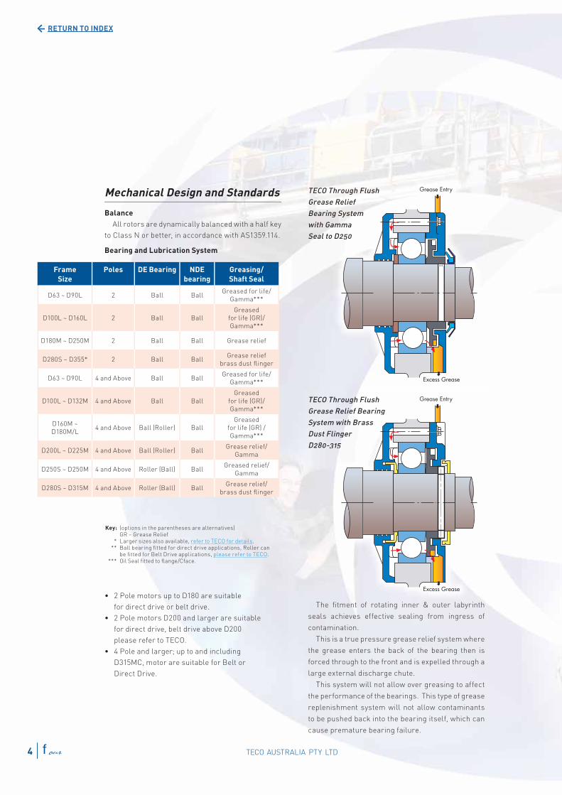
TECO Through Flush
Grease Relief
Bearing System
with Gamma
Seal to D250
TECO Through Flush
Grease Relief Bearing
System with Brass
Dust Flinger
D280-315
The fi tment of rotating inner & outer labyrinth
seals achieves effective sealing from ingress of
contamination.
This is a true pressure grease relief system where
the grease enters the back of the bearing then is
forced through to the front and is expelled through a
large external discharge chute.
This system will not allow over greasing to affect
the performance of the bearings. This type of grease
replenishment system will not allow contaminants
to be pushed back into the bearing itself, which can
cause premature bearing failure.
Frame
Size
Poles DE Bearing NDE
bearing
Greasing/
Shaft Seal
D63 ~ D90L 2 Ball BallGreased for life/
Gamma***
D100L ~ D160L 2 Ball Ball
Greased
for life (GR)/
Gamma***
D180M ~ D250M 2 Ball Ball Grease relief
D280S ~ D355* 2 Ball BallGrease relief
brass dust fl inger
D63 ~ D90L 4 and Above Ball BallGreased for life/
Gamma***
D100L ~ D132M 4 and Above Ball Ball
Greased
for life (GR)/
Gamma***
D160M ~
D180M/L4 and Above Ball (Roller) Ball
Greased
for life (GR) /
Gamma***
D200L ~ D225M 4 and Above Ball (Roller) BallGrease relief/
Gamma
D250S ~ D250M 4 and Above Roller (Ball) BallGreased relief/
Gamma
D280S ~ D315M 4 and Above Roller (Ball) BallGrease relief/
brass dust fl inger
Key: (options in the parentheses are alternatives) GR – Grease Relief * Larger sizes also available, refer to TECO for details. ** Ball bearing fi tted for direct drive applications, Roller can
be fi tted for Belt Drive applications, please refer to TECO. *** Oil Seal fi tted to fl ange/Cface.
Throughgh Flush
e Relieief Bearinngg gg
m witth Brasss
Flingger
331515
Through Flush
e Relief
ng SyS stem
amma
o D250
TECO AUSTRALIA PTY LTD4 four
RETURN TO INDEX
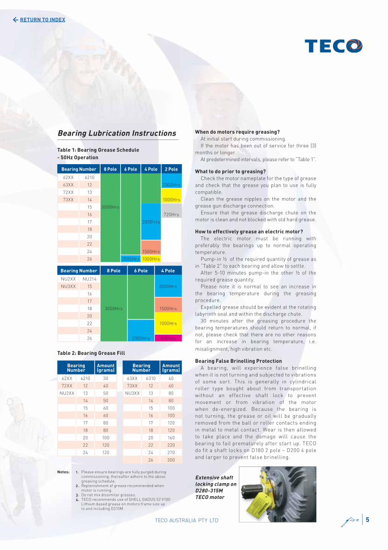
Bearing Lubrication Instructions
Table 1: Bearing Grease Schedule
- 50Hz Operation
Table 2: Bearing Grease Fill
When do motors require greasing?
At initial start during commissioning.
If the motor has been out of service for three (3)
months or longer.
At predetermined intervals, please refer to “Table 1”.
What to do prior to greasing?
Check the motor nameplate for the type of grease
and check that the grease you plan to use is fully
compatible.
Clean the grease nipples on the motor and the
grease gun discharge connection.
Ensure that the grease discharge chute on the
motor is clean and not blocked with old hard grease.
How to effectively grease an electric motor?
The electric motor must be running with
preferably the bearings up to normal operating
temperature.
Pump-in ½ of the required quantity of grease as
in “Table 2” to each bearing and allow to settle.
After 5-10 minutes pump-in the other ½ of the
required grease quantity.
Please note it is normal to see an increase in
the bearing temperature during the greasing
procedure.
Expelled grease should be evident at the rotating
labyrinth seal and within the discharge chute.
30 minutes after the greasing procedure the
bearing temperatures should return to normal, if
not, please check that there are no other reasons
for an increase in bearing temperature, i.e.
misalignment, high vibration etc.
Bearing False Brinelling Protection
A bearing, will experience false brinelling
when it is not turning and subjected to vibrations
of some sort. This is generally in cylindrical
roller type bought about from transportation
without an effective shaft lock to prevent
movement or from vibration of the motor
when de-energized. Because the bearing is
not turning, the grease or oil will be gradually
removed from the ball or roller contacts ending
in metal to metal contact. Wear is then allowed
to take place and the damage will cause the
bearing to fail prematurely after start up. TECO
do fit a shaft locks on D180 2 pole ~ D200 4 pole
and larger to prevent false brinelling.
Bearing Number 8 Pole 6 Pole 4 Pole 2 Pole
62XX 6210
63XX 12 2000Hrs
72XX 13
73XX 14 1000Hrs
15 3000Hrs
16 720Hrs
17 2000Hrs
18
20
22
24 1500Hrs
26 2000Hrs 1000Hrs
Bearing Number 8 Pole 6 Pole 4 Pole
NU2XX NU214
NU3XX 15 2000Hrs
16
17
18 3000Hrs 1500Hrs
20
22 1000Hrs
24
26 2000Hrs 500Hrs
Bearing Number
Amount (grams)
62XX 6210 30
72XX 12 40
NU2XX 13 50
14 50
15 60
16 60
17 80
18 80
20 100
22 120
24 120
Bearing Number
Amount (grams)
63XX 6310 40
73XX 12 60
NU3XX 13 80
14 80
15 100
16 100
17 120
18 120
20 160
22 220
24 270
26 300
Extensive shaft
locking clamp on
D280-315M
TECO motor
Notes: 1. Please ensure bearings are fully purged during commissioning, thereafter adhere to the above greasing schedule. 2. Replenishment of grease recommended when
motor is running. 3. Do not mix dissimilar greases. 4. TECO recommends use of SHELL GADUS S2 V100 Lithium based grease on motors frame size up to and including D315M.
5TECO AUSTRALIA PTY LTD fi ve
RETURN TO INDEX
Cooling System
Cooling is Totally Enclosed Fan Cooled (TEFC), with
integrally cast cooling fi ns on frame and endshields,
fi tted with external fan (IC411) to AS1359.106
The cooling fans are bi-directional and low noise
as standard.
Finish
All external components are shot blast to a near
white fi nish. A durable coat of Alkyd Resin primer
giving excellent corrosion protection follows this
preparation. The complete motor is then fi nish
coated with Alkyd Resin Gloss Enamel in TECO Grey
(Munsell 7.5BG 4/2).
Other paint systems and colours are available
upon request, including chemical duty two pack
epoxy paint systems.
Hardware
All hardware is electro zinc plated for better
corrosion resistance.
Stainless steel hardware can be offered as an
alternative, please contact TECO for the surcharge
to provide this feature.
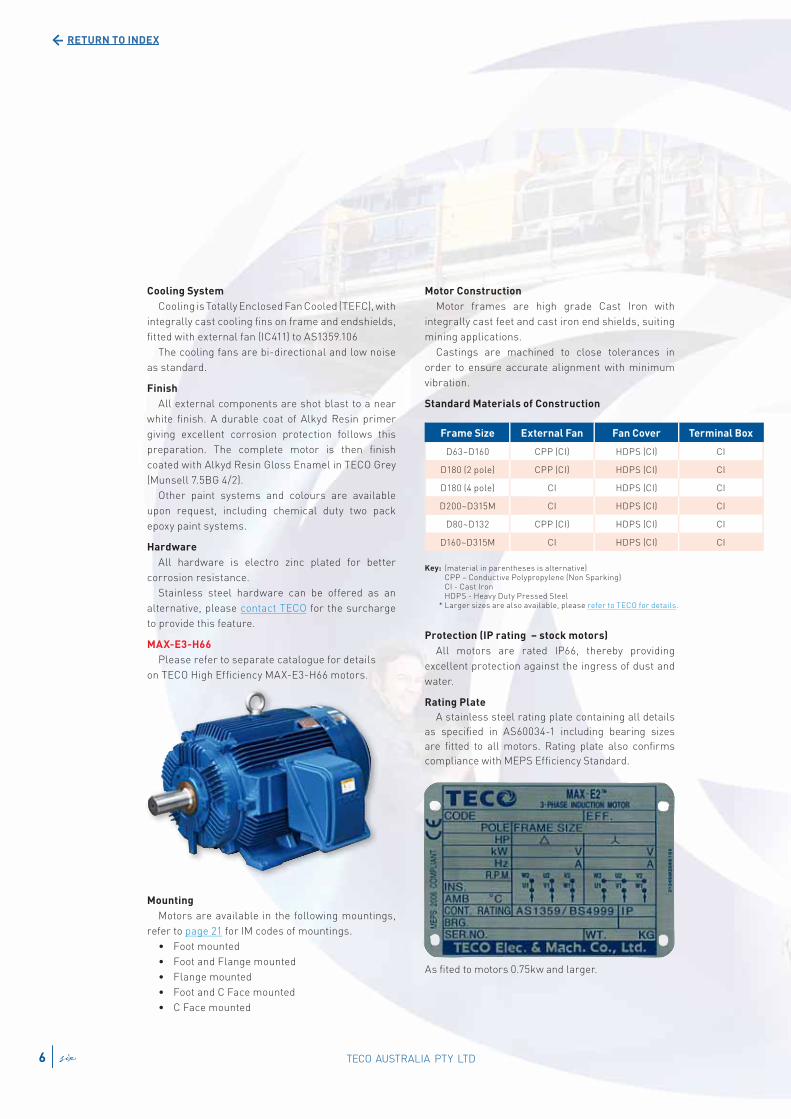
MAX-E3-H66
Please refer to separate catalogue for details
on TECO High Effi ciency MAX-E3-H66 motors.
Mounting
Motors are available in the following mountings,
refer to page 21 for IM codes of mountings.
• Foot mounted
• Foot and Flange mounted
• Flange mounted
• Foot and C Face mounted
• C Face mounted
Key: (material in parentheses is alternative) CPP – Conductive Polypropylene (Non Sparking) CI - Cast Iron HDPS - Heavy Duty Pressed Steel * Larger sizes are also available, please refer to TECO for details.
Motor Construction
Motor frames are high grade Cast Iron with
integrally cast feet and cast iron end shields, suiting
mining applications.
Castings are machined to close tolerances in
order to ensure accurate alignment with minimum
vibration.
Standard Materials of Construction
Protection (IP rating – stock motors)
All motors are rated IP66, thereby providing
excellent protection against the ingress of dust and
water.
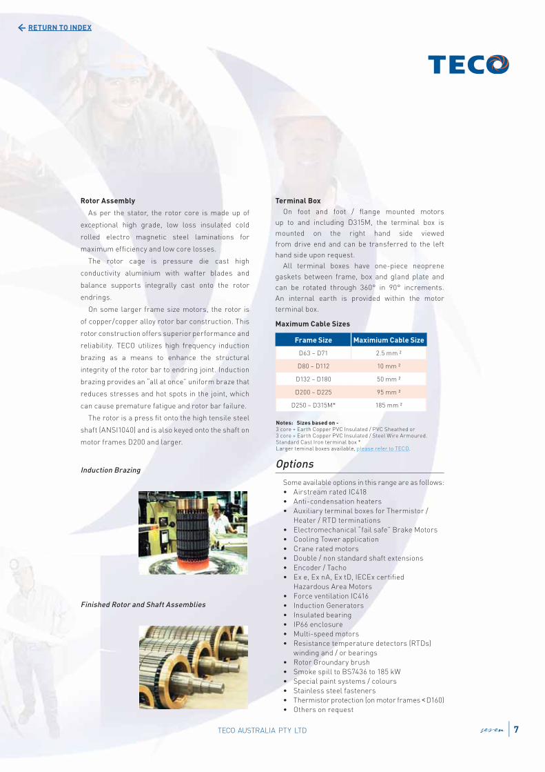
Rating Plate
A stainless steel rating plate containing all details
as specifi ed in AS60034-1 including bearing sizes
are fi tted to all motors. Rating plate also confi rms
compliance with MEPS Effi ciency Standard.
Frame Size External Fan Fan Cover Terminal Box
D63~D160 CPP (CI) HDPS (CI) CI
D180 (2 pole) CPP (CI) HDPS (CI) CI
D180 (4 pole) CI HDPS (CI) CI
D200~D315M CI HDPS (CI) CI
D80~D132 CPP (CI) HDPS (CI) CI
D160~D315M CI HDPS (CI) CI
As fi ted to motors 0.75kw and larger.
TECO AUSTRALIA PTY LTD6 six
RETURN TO INDEX
Rotor Assembly
As per the stator, the rotor core is made up of
exceptional high grade, low loss insulated cold
rolled electro magnetic steel laminations for
maximum effi ciency and low core losses.
The rotor cage is pressure die cast high
conductivity aluminium with wafter blades and
balance supports integrally cast onto the rotor
endrings.
On some larger frame size motors, the rotor is
of copper/copper alloy rotor bar construction. This
rotor construction offers superior performance and
reliability. TECO utilizes high frequency induction
brazing as a means to enhance the structural
integrity of the rotor bar to endring joint. Induction
brazing provides an “all at once” uniform braze that
reduces stresses and hot spots in the joint, which
can cause premature fatigue and rotor bar failure.
The rotor is a press fi t onto the high tensile steel
shaft (ANSI1040) and is also keyed onto the shaft on
motor frames D200 and larger.
Induction Brazing
Finished Rotor and Shaft Assemblies
Terminal Box
On foot and foot / fl ange mounted motors
up to and including D315M, the terminal box is
mounted on the right hand side viewed
from drive end and can be transferred to the left
hand side upon request.
All terminal boxes have one-piece neoprene
gaskets between frame, box and gland plate and
can be rotated through 360° in 90° increments.
An internal earth is provided within the motor
terminal box.
Maximum Cable Sizes
Options
Some available options in this range are as follows:
• Airstream rated IC418
• Anti-condensation heaters
• Auxiliary terminal boxes for Thermistor /
Heater / RTD terminations
• Electromechanical “fail safe” Brake Motors
• Cooling Tower application
• Crane rated motors
• Double / non standard shaft extensions
• Encoder / Tacho
• Ex e, Ex nA, Ex tD, IECEx certifi ed
Hazardous Area Motors
• Force ventilation IC416
• Induction Generators
• Insulated bearing
• IP66 enclosure
• Multi-speed motors
• Resistance temperature detectors (RTDs)
winding and / or bearings
• Rotor Groundary brush
• Smoke spill to BS7436 to 185 kW
• Special paint systems / colours
• Stainless steel fasteners
• Thermistor protection (on motor frames <D160)
• Others on request
Frame Size Maximium Cable Size
D63 ~ D71 2.5 mm ²
D80 ~ D112 10 mm ²
D132 ~ D180 50 mm ²
D200 ~ D225 95 mm ²
D250 ~ D315M* 185 mm ²
Notes: Sizes based on - 3 core + Earth Copper PVC Insulated / PVC Sheathed or 3 core + Earth Copper PVC Insulated / Steel Wire Armoured. Standard Cast Iron terminal box * Larger teminal boxes available, please refer to TECO.
seven 7TECO AUSTRALIA PTY LTD

RETURN TO INDEX
Typical Performance Data MAX-E2
TECO Cast Iron TEFC 3-Phase Squirrel Cage Induction Motors
63 to 315 Frame (415V 50Hz)
Output
kW
Full
Load
Speed
RPM
Frame
Size
Effi ciency Power Factor Current Torque Inertia Noise
Level
dB(A)
Weight
Foot
Mount
Kgs
Full
Load
(%)
3/4
Load
(%)
1/2
Load
(%)
Full
Load
(%)
3/4
Load
(%)
1/2
Load
(%)
Full
Load
(A)
Locked
Rotor
(%)
Full
Load
N-m
Locked
Rotor
%FLT
Pull
Up
%FLT
Break-
Down
%FLT
Rotor
J=GD2/4
Kg-m2
MaxLoad
J=GD2/4
Kg-m2
0.18 2740 63 61.0 59.5 55.0 77.5 69.0 57.0 0.55 455 0.63 330 330 330 0.0005 0.022 52 9
1350 63 63.5 63.0 58.0 70.0 61.0 49.0 0.58 431 1.27 240 230 260 0.0008 0.103 48 11
910 71 61.0 57.0 50.0 64.0 55.0 44.0 0.66 379 1.89 260 240 280 0.0018 0.175 45 12
705 80 52.0 48.0 39.0 47.0 41.0 34.0 1.06 302 2.44 360 350 370 0.0025 0.543 44 16
0.37 2800 71 75.0 74.0 70.0 85.0 78.0 64.0 0.81 593 1.26 320 270 310 0.0008 0.043 54 12
1405 71 74.5 73.0 68.5 69.5 60.5 48.0 1.00 530 2.51 325 270 305 0.0013 0.198 50 13
920 80 72.5 72.0 68.5 72.0 62.5 49.0 0.99 535 3.84 230 215 240 0.0025 0.338 49 18
710 90S 70.5 68.0 62.5 60.0 51.0 39.5 1.23 388 4.98 195 190 265 0.0045 1.04 49 22
0.55 2780 71 73.0 72.0 68.0 83.0 75.0 62.0 1.28 563 1.89 300 260 280 0.0008 0.062 53 16
1405 80 71.5 70.5 65.0 74.0 65.0 52.0 1.47 524 3.74 260 230 280 0.0018 0.291 48 18
910 80 68.0 68.0 63.0 72.0 62.0 49.0 1.59 365 5.77 230 210 230 0.0030 0.498 48 18
690 90L 70.0 70.0 66.0 70.0 61.0 49.0 1.59 365 7.61 170 145 205 0.0058 1.54 47 27
0.75 2850 80** 82.4 83.0 81.0 83.0 76.0 60.0 1.53 784 2.51 380 310 370 0.0015 0.081 57 18
1425 80 82.5 81.0 77.0 70.5 59.5 45.5 1.79 670 5.03 370 340 370 0.0033 0.353 50 18
930 90S 78.0 77.0 75.0 68.0 59.0 45.5 1.97 508 7.70 210 200 250 0.0048 0.913 54 25
695 100L** 76.5 76.0 72.5 60.0 51.0 39.0 2.27 441 10.3 230 215 230 0.0103 1.89 49 31
1.1 2815 80 83.8 83.0 81.0 82.0 75.0 60.0 2.23 762 3.73 320 280 340 0.0018 0.110 53 21
1440 90S 84.0 84.0 82.5 77.5 69.0 55.0 2.35 766 7.30 250 190 270 0.0043 0.523 46 27
930 90L 82.0 80.0 77.5 67.5 58.0 44.5 2.76 543 11.3 220 220 270 0.0065 1.40 42 26
695 100L 78.0 79.5 77.0 64.5 55.5 43.0 3.04 493 15.1 210 200 215 0.0135 2.74 49 37
1.5 2885 90S 85.0 85.0 83.0 83.0 76.0 63.0 2.96 845 4.97 300 260 360 0.0028 0.145 54 24
1450 90L 85.8 84.5 82.0 73.5 64.5 50.5 3.31 755 9.9 320 240 340 0.0058 0.670 46 30
930 100L 83.0 83.0 81.0 73.0 65.0 52.0 3.44 523 15.4 220 190 220 0.0138 1.83 44 36
705 112M 79.5 79.0 77.0 59.0 49.0 39.0 4.45 449 20.3 200 170 230 0.0178 3.65 49 45
2.2 2885 90L 87.1 86.5 85.0 85.0 79.0 67.0 4.13 896 7.28 290 250 360 0.0035 0.213 59 29
1445 100L 86.5 85.5 84.0 82.5 74.5 60.5 4.29 862 14.5 260 180 310 0.0103 1.04 46 37
950 112M 84.5 85.5 85.5 72.0 65.5 54.0 5.03 537 22.1 175 165 220 0.0208 2.68 44 43
710 132S 82.0 81.5 79.0 65.0 56.0 43.0 5.74 523 29.6 250 230 280 0.0345 5.29 49 65
3 2870 100L** 88.5 88.5 87.5 86.5 81.5 70.5 5.45 972 9.98 350 330 350 0.0063 0.280 57 38
1440 100L 87.6 87.5 87.0 83.5 78.0 65.0 5.71 788 19.9 240 170 290 0.0125 1.34 46 43
965 132S** 88.5 88.5 88.0 77.0 70.0 58.0 6.12 670 29.7 190 180 290 0.0385 3.50 51 71
710 132M 83.5 83.5 81.0 65.0 55.0 42.0 7.69 520 40.4 250 235 290 0.0405 6.97 50 75
4 2890 112M** 89.5 90.0 89.5 89.0 88.0 81.0 6.99 815 13.2 260 190 290 0.0115 0.383 57 48
1450 112M 89.0 89.0 88.0 83.0 76.5 65.0 7.53 890 26.3 280 160 310 0.0208 1.81 48 48
965 132M** 89.5 98.5 88.5 78.0 71.0 59.0 7.97 753 39.6 210 190 290 0.0513 4.75 51 87
720 160M 84.5 84.0 81.5 73.0 65.0 52.5 9.02 554 53.1 200 180 250 0.0858 9.51 51 118
5.5 2930 132S** 91.5 92.0 91.0 86.0 82.0 73.0 9.72 885 17.9 230 210 320 0.0188 0.505 64 71
1465 132S 90.5 90.5 89.5 79.0 72.0 59.5 10.7 794 35.9 260 190 280 0.0330 2.37 53 72
960 132M** 89.0 89.5 89.5 81.0 76.0 65.5 10.6 623 54.7 190 180 270 0.0540 6.33 47 90
715 160M 86.0 85.5 83.5 73.0 65.0 52.0 12.2 533 73.5 170 160 230 0.0858 12.7 54 118
7.5 2920 132S** 91.0 90.5 90.0 85.0 81.5 73.0 13.5 644 24.5 190 150 250 0.0188 0.670 64 84
1465 132M 91.0 91.0 90.5 81.0 74.5 62.5 14.2 754 48.9 260 190 270 0.0430 3.10 56 82
970 160M** 91.0 90.5 90.0 79.0 75.5 61.0 14.5 724 73.8 250 230 290 0.1258 8.34 55 138
720 160L 87.5 87.0 85.0 72.0 64.0 51.0 16.6 572 99.5 195 185 270 0.1465 16.6 55 155
Notes: 1. All fi gures are based on tests carried out on 415 Volt3-Phase Motors. 2. Test Method: AS1359.5, Method B. 3. Tolerance: refer page 30 4. ** motors comply to MEPS 2006 High Effi ciency requirements. 5. dB(A): Mean Sound Pressure Level on no load at 1 metre. 6. Motor data 8 pole and slower speeds not listed available on request. 7. Data subject to change without notice.
TECO AUSTRALIA PTY LTD8 TECO AUSTRALIA PTY LTDeight
RETURN TO INDEX
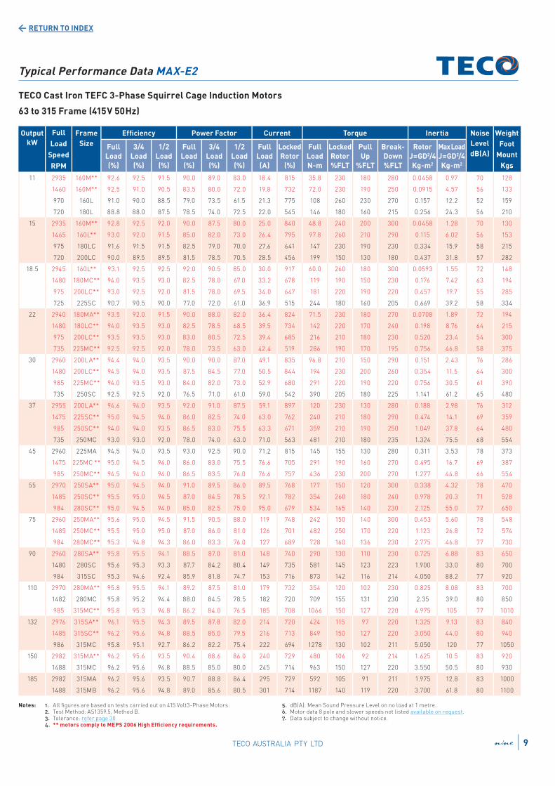
Typical Performance Data MAX-E2
TECO Cast Iron TEFC 3-Phase Squirrel Cage Induction Motors
63 to 315 Frame (415V 50Hz)
Output
kW
Full
Load
Speed
RPM
Frame
Size
Effi ciency Power Factor Current Torque Inertia Noise
Level
dB(A)
Weight
Foot
Mount
Kgs
Full
Load
(%)
3/4
Load
(%)
1/2
Load
(%)
Full
Load
(%)
3/4
Load
(%)
1/2
Load
(%)
Full
Load
(A)
Locked
Rotor
(%)
Full
Load
N-m
Locked
Rotor
%FLT
Pull
Up
%FLT
Break-
Down
%FLT
Rotor
J=GD2/4
Kg-m2
MaxLoad
J=GD2/4
Kg-m2
11 2935 160M** 92.6 92.5 91.5 90.0 89.0 83.0 18.4 815 35.8 230 180 280 0.0458 0.97 70 128
1460 160M** 92.5 91.0 90.5 83.5 80.0 72.0 19.8 732 72.0 230 190 250 0.0915 4.57 56 133
970 160L 91.0 90.0 88.5 79.0 73.5 61.5 21.3 775 108 260 230 270 0.157 12.2 52 159
720 180L 88.8 88.0 87.5 78.5 74.0 72.5 22.0 545 146 180 160 215 0.256 24.3 56 210
15 2935 160M** 92.8 92.5 92.0 90.0 87.5 80.0 25.0 840 48.8 240 200 300 0.0458 1.28 70 130
1465 160L** 93.0 92.0 91.5 85.0 82.0 73.0 26.4 795 97.8 260 210 290 0.115 6.02 56 153
975 180LC 91.6 91.5 91.5 82.5 79.0 70.0 27.6 641 147 230 190 230 0.334 15.9 58 215
720 200LC 90.0 89.5 89.5 81.5 78.5 70.5 28.5 456 199 150 130 180 0.437 31.8 57 282
18.5 2945 160L** 93.1 92.5 92.5 92.0 90.5 85.0 30.0 917 60.0 260 180 300 0.0593 1.55 72 148
1480 180MC** 94.0 93.5 93.0 82.5 78.0 67.0 33.2 678 119 190 150 230 0.176 7.42 63 194
975 200LC** 93.0 92.5 92.0 81.5 78.0 69.5 34.0 647 181 220 190 220 0.457 19.7 55 285
725 225SC 90.7 90.5 90.0 77.0 72.0 61.0 36.9 515 244 180 160 205 0.669 39.2 58 334
22 2940 180MA** 93.5 92.0 91.5 90.0 88.0 82.0 36.4 824 71.5 230 180 270 0.0708 1.89 72 194
1480 180LC** 94.0 93.5 93.0 82.5 78.5 68.5 39.5 734 142 220 170 240 0.198 8.76 64 215
975 200LC** 93.5 93.5 93.0 83.0 80.5 72.5 39.4 685 216 210 180 230 0.520 23.4 54 300
735 225MC** 92.5 92.5 92.0 78.0 73.5 63.0 42.4 519 286 190 170 195 0.756 46.8 58 375
30 2960 200LA** 94.4 94.0 93.5 90.0 90.0 87.0 49.1 835 96.8 210 150 290 0.151 2.43 76 286
1480 200LC** 94.5 94.0 93.5 87.5 84.5 77.0 50.5 844 194 230 200 260 0.354 11.5 64 300
985 225MC** 94.0 93.5 93.0 84.0 82.0 73.0 52.9 680 291 220 190 220 0.756 30.5 61 390
735 250SC 92.5 92.5 92.0 76.5 71.0 61.0 59.0 542 390 205 180 225 1.141 61.2 65 480
37 2955 200LA** 94.6 94.0 93.5 92.0 91.0 87.5 59.1 897 120 230 130 280 0.188 2.98 76 312
1475 225SC** 95.0 94.5 94.0 86.0 82.5 74.0 63.0 762 240 210 180 290 0.474 14.1 69 359
985 250SC** 94.0 94.0 93.5 86.5 83.0 75.5 63.3 671 359 210 190 250 1.049 37.8 64 480
735 250MC 93.0 93.0 92.0 78.0 74.0 63.0 71.0 563 481 210 180 235 1.324 75.5 68 554
45 2960 225MA 94.5 94.0 93.5 93.0 92.5 90.0 71.2 815 145 155 130 280 0.311 3.53 78 373
1475 225MC ** 95.0 94.5 94.0 86.0 83.0 75.5 76.6 705 291 190 160 270 0.495 16.7 69 387
985 250MC** 94.5 94.0 94.0 86.5 83.5 76.0 76.6 757 436 230 200 270 1.277 44.8 66 554
55 2970 250SA** 95.0 94.5 94.0 91.0 89.5 86.0 89.5 768 177 150 120 300 0.338 4.32 78 470
1485 250SC** 95.5 95.0 94.5 87.0 84.5 78.5 92.1 782 354 260 180 240 0.978 20.3 71 528
984 280SC** 95.0 94.5 94.0 85.0 82.5 75.0 95.0 679 534 165 140 230 2.125 55.0 77 650
75 2960 250MA** 95.6 95.0 94.5 91.5 90.5 88.0 119 748 242 150 140 300 0.453 5.60 78 548
1485 250MC** 95.5 95.0 95.0 87.0 86.0 81.0 126 701 482 250 170 220 1.123 26.8 72 574
984 280MC** 95.3 94.8 94.3 86.0 83.3 76.0 127 689 728 160 136 230 2.775 46.8 77 730
90 2960 280SA** 95.8 95.5 94.1 88.5 87.0 81.0 148 740 290 130 110 230 0.725 6.88 83 650
1480 280SC 95.6 95.3 93.3 87.7 84.2 80.4 149 735 581 145 123 223 1.900 33.0 80 700
984 315SC 95.3 94.6 92.4 85.9 81.8 74.7 153 716 873 142 116 214 4.050 88.2 77 920
110 2970 280MA** 95.8 95.5 94.1 89.2 87.5 81.0 179 732 354 120 102 230 0.825 8.08 83 700
1482 280MC 95.8 95.2 94.4 88.0 84.5 78.5 182 720 709 155 131 230 2.35 39.0 80 850
985 315MC** 95.8 95.3 94.8 86.2 84.0 76.5 185 708 1066 150 127 220 4.975 105 77 1010
132 2976 315SA** 96.1 95.5 94.3 89.5 87.8 82.0 214 720 424 115 97 220 1.325 9.13 83 840
1485 315SC** 96.2 95.6 94.8 88.5 85.0 79.5 216 713 849 150 127 220 3.050 44.0 80 940
986 315MC 95.8 95.1 92.7 86.2 82.2 75.4 222 694 1278 130 102 211 5.050 120 77 1050
150 2982 315MA** 96.2 95.6 93.5 90.4 88.6 86.0 240 729 480 106 92 214 1.625 10.5 83 920
1488 315MC 96.2 95.6 94.8 88.5 85.0 80.0 245 714 963 150 127 220 3.550 50.5 80 930
185 2982 315MA 96.2 95.6 93.5 90.7 88.8 86.4 295 729 592 105 91 211 1.975 12.8 83 1000
1488 315MB 96.2 95.6 94.8 89.0 85.6 80.5 301 714 1187 140 119 220 3.700 61.8 80 1100
Notes: 1. All fi gures are based on tests carried out on 415 Volt3-Phase Motors. 2. Test Method: AS1359.5, Method B. 3. Tolerance: refer page 30 4. ** motors comply to MEPS 2006 High Effi ciency requirements.
5. dB(A): Mean Sound Pressure Level on no load at 1 metre. 6. Motor data 8 pole and slower speeds not listed available on request. 7. Data subject to change without notice.
9TECO AUSTRALIA PTY LTD nine
RETURN TO INDEX
TECO AUSTRALIA PTY LTDten10 TECO AUSTRALIA PTY LTD
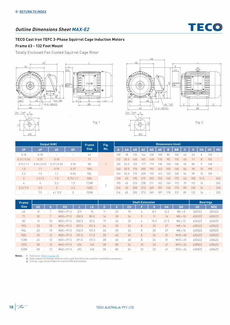
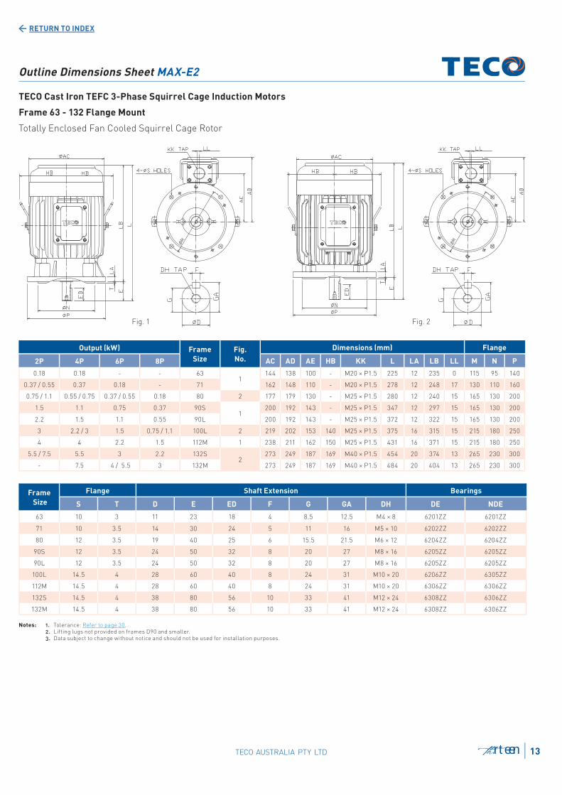
Outline Dimensions Sheet MAX-E2
TECO Cast Iron TEFC 3-Phase Squirrel Cage Induction Motors
Frame 63 - 132 Foot Mount
Totally Enclosed Fan Cooled Squirrel Cage Rotor
Output (kW) Frame
Size
Fig.
No.
Dimensions (mm)
2P 4P 6P 8P A AA AB AC AD AE B BB C H HA HC HD
0.18 0.18 - - 63
1
100 28 120 144 138 100 80 100 40 63 8 135 -
0.37 / 0.55 0.37 0.18 - 71 112 35.5 140 162 148 110 90 115 45 71 8 152 -
0.75 / 1.1 0.55 / 0.75 0.37 / 0.55 0.18 80 125 35.5 155 177 179 130 100 130 50 80 9 168 -
1.5 1.1 0.75 0.37 90S 140 35.5 170 200 192 143 100 130 56 90 10 190 -
2.2 1.5 1.1 0.55 90L 140 35.5 170 200 192 143 125 150 56 90 10 190 -
3 2.2 / 3 1.5 0.75 / 1.1 100L
2
160 45 195 219 202 153 140 175 63 100 12.5 - 243
4 4 2.2 1.5 112M 190 45 224 238 211 162 140 175 70 112 14 - 265
5.5 / 7.5 5.5 3 2.2 132S 216 45 250 273 249 187 140 175 89 132 16 - 310
- 7.5 4 / 5.5 3 132M 216 45 250 273 249 187 178 212 89 132 16 - 310
Notes: 1. Tolerance: Refer to page 30. 2. Data subject to change without notice and should not be used for installation purposes. 3. Lifting Lugs not provided on frames D90 and smaller.
Frame
Size
Shaft Extension Bearings
HE K KK L LE D E ED F G GA DH DE NDE
63 10 7 M20 × P1.5 219 76 11 23 18 4 8.5 12.5 M4 × 8 6201ZZ 6201ZZ
71 35 7 M20 × P1.5 250.5 85.5 14 30 24 5 11 16 M5 × 10 6202ZZ 6202ZZ
80 13 10 M25 × P1.5 282.5 92.5 19 40 25 6 15.5 21.5 M6 × 12 6204ZZ 6204ZZ
90S 23 10 M25 × P1.5 307.5 101.5 24 50 32 8 20 27 M8 × 16 6205ZZ 6205ZZ
90L 23 10 M25 × P1.5 332.5 101.5 24 50 32 8 20 27 M8 × 16 6205ZZ 6205ZZ
100L 33 12 M25 × P1.5 374.5 111.5 28 60 40 8 24 31 M10 × 20 6206ZZ 6305ZZ
112M 45 12 M25 × P1.5 391.5 121.5 28 60 40 8 24 31 M10 × 20 6306ZZ 6306ZZ
132S 58 12 M40 × P1.5 454 145 38 80 56 10 33 41 M12 × 24 6308ZZ 6306ZZ
132M 58 12 M40 × P1.5 492 145 38 80 56 10 33 41 M12 × 24 6308ZZ 6306ZZ
Fig. 1 Fig. 2
RETURN TO INDEX
eleven 11TECO AUSTRALIA PTY LTD
Output (kW) Frame
Size
Fig.
No.
Dimensions (mm)
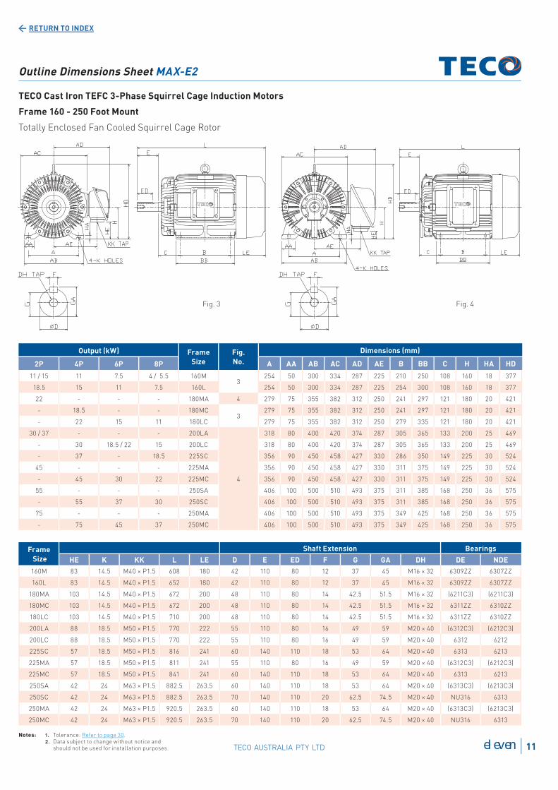
2P 4P 6P 8P A AA AB AC AD AE B BB C H HA HD
11 / 15 11 7.5 4 / 5.5 160M3
254 50 300 334 287 225 210 250 108 160 18 377
18.5 15 11 7.5 160L 254 50 300 334 287 225 254 300 108 160 18 377
22 - - - 180MA 4 279 75 355 382 312 250 241 297 121 180 20 421
- 18.5 - - 180MC3
279 75 355 382 312 250 241 297 121 180 20 421
- 22 15 11 180LC 279 75 355 382 312 250 279 335 121 180 20 421
30 / 37 - - - 200LA
4
318 80 400 420 374 287 305 365 133 200 25 469
- 30 18.5 / 22 15 200LC 318 80 400 420 374 287 305 365 133 200 25 469
- 37 - 18.5 225SC 356 90 450 458 427 330 286 350 149 225 30 524
45 - - - 225MA 356 90 450 458 427 330 311 375 149 225 30 524
- 45 30 22 225MC 356 90 450 458 427 330 311 375 149 225 30 524
55 - - - 250SA 406 100 500 510 493 375 311 385 168 250 36 575
- 55 37 30 250SC 406 100 500 510 493 375 311 385 168 250 36 575
75 - - - 250MA 406 100 500 510 493 375 349 425 168 250 36 575
- 75 45 37 250MC 406 100 500 510 493 375 349 425 168 250 36 575
Notes: 1. Tolerance: Refer to page 30. 2. Data subject to change without notice and should not be used for installation purposes.
Frame
Size
Shaft Extension Bearings
HE K KK L LE D E ED F G GA DH DE NDE
160M 83 14.5 M40 × P1.5 608 180 42 110 80 12 37 45 M16 × 32 6309ZZ 6307ZZ
160L 83 14.5 M40 × P1.5 652 180 42 110 80 12 37 45 M16 × 32 6309ZZ 6307ZZ
180MA 103 14.5 M40 × P1.5 672 200 48 110 80 14 42.5 51.5 M16 × 32 (6211C3) (6211C3)
180MC 103 14.5 M40 × P1.5 672 200 48 110 80 14 42.5 51.5 M16 × 32 6311ZZ 6310ZZ
180LC 103 14.5 M40 × P1.5 710 200 48 110 80 14 42.5 51.5 M16 × 32 6311ZZ 6310ZZ
200LA 88 18.5 M50 × P1.5 770 222 55 110 80 16 49 59 M20 × 40 (6312C3) (6212C3)
200LC 88 18.5 M50 × P1.5 770 222 55 110 80 16 49 59 M20 × 40 6312 6212
225SC 57 18.5 M50 × P1.5 816 241 60 140 110 18 53 64 M20 × 40 6313 6213
225MA 57 18.5 M50 × P1.5 811 241 55 110 80 16 49 59 M20 × 40 (6312C3) (6212C3)
225MC 57 18.5 M50 × P1.5 841 241 60 140 110 18 53 64 M20 × 40 6313 6213
250SA 42 24 M63 × P1.5 882.5 263.5 60 140 110 18 53 64 M20 × 40 (6313C3) (6213C3)
250SC 42 24 M63 × P1.5 882.5 263.5 70 140 110 20 62.5 74.5 M20 × 40 NU316 6313
250MA 42 24 M63 × P1.5 920.5 263.5 60 140 110 18 53 64 M20 × 40 (6313C3) (6213C3)
250MC 42 24 M63 × P1.5 920.5 263.5 70 140 110 20 62.5 74.5 M20 × 40 NU316 6313
Outline Dimensions Sheet MAX-E2
TECO Cast Iron TEFC 3-Phase Squirrel Cage Induction Motors
Frame 160 - 250 Foot Mount
Totally Enclosed Fan Cooled Squirrel Cage Rotor
Fig. 4Fig. 3
RETURN TO INDEX
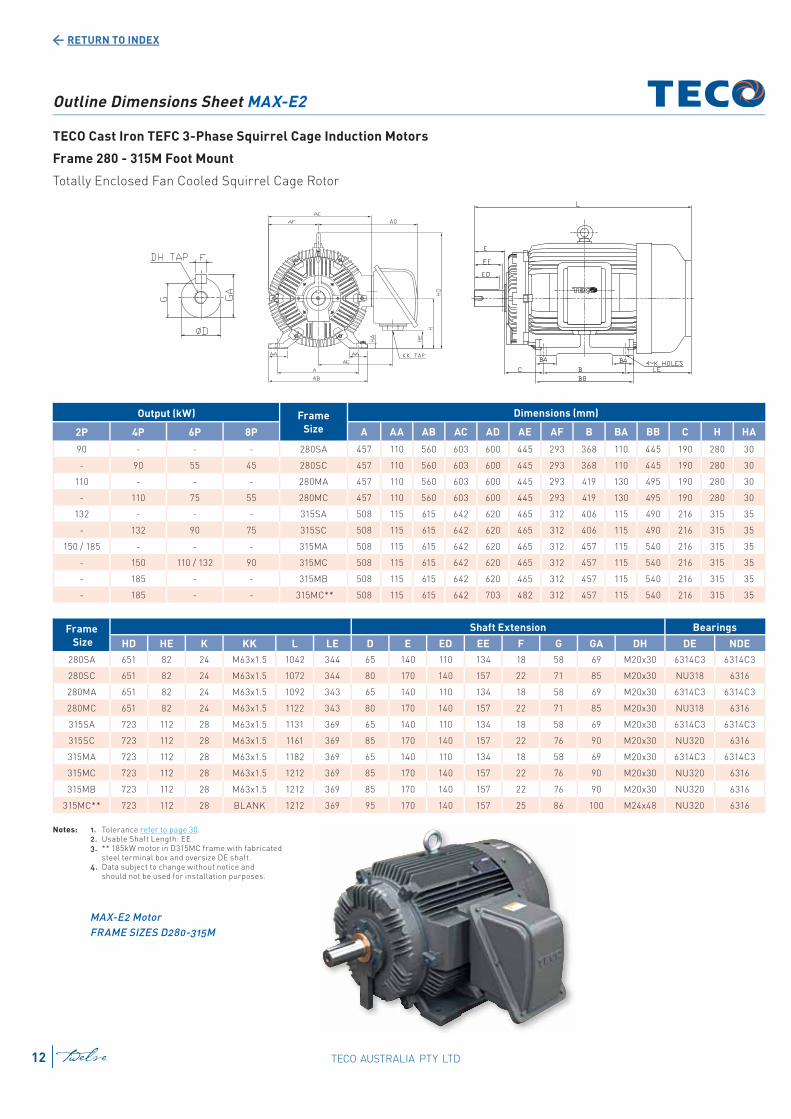
Outline Dimensions Sheet MAX-E2
TECO Cast Iron TEFC 3-Phase Squirrel Cage Induction Motors
Frame 280 - 315M Foot Mount
Totally Enclosed Fan Cooled Squirrel Cage Rotor
Notes: 1. Tolerance refer to page 30. 2. Usable Shaft Length: EE 3. ** 185kW motor in D315MC frame with fabricated
steel terminal box and oversize DE shaft. 4. Data subject to change without notice and
should not be used for installation purposes.
MAX-E2 Motor
FRAME SIZES D280-315M
Output (kW) Frame
Size
Dimensions (mm)
2P 4P 6P 8P A AA AB AC AD AE AF B BA BB C H HA
90 - - - 280SA 457 110 560 603 600 445 293 368 110 445 190 280 30
- 90 55 45 280SC 457 110 560 603 600 445 293 368 110 445 190 280 30
110 - - - 280MA 457 110 560 603 600 445 293 419 130 495 190 280 30
- 110 75 55 280MC 457 110 560 603 600 445 293 419 130 495 190 280 30
132 - - - 315SA 508 115 615 642 620 465 312 406 115 490 216 315 35
- 132 90 75 315SC 508 115 615 642 620 465 312 406 115 490 216 315 35
150 / 185 - - - 315MA 508 115 615 642 620 465 312 457 115 540 216 315 35
- 150 110 / 132 90 315MC 508 115 615 642 620 465 312 457 115 540 216 315 35
- 185 - - 315MB 508 115 615 642 620 465 312 457 115 540 216 315 35
- 185 - - 315MC** 508 115 615 642 703 482 312 457 115 540 216 315 35
Frame
Size
Shaft Extension Bearings
HD HE K KK L LE D E ED EE F G GA DH DE NDE
280SA 651 82 24 M63x1.5 1042 344 65 140 110 134 18 58 69 M20x30 6314C3 6314C3
280SC 651 82 24 M63x1.5 1072 344 80 170 140 157 22 71 85 M20x30 NU318 6316
280MA 651 82 24 M63x1.5 1092 343 65 140 110 134 18 58 69 M20x30 6314C3 6314C3
280MC 651 82 24 M63x1.5 1122 343 80 170 140 157 22 71 85 M20x30 NU318 6316
315SA 723 112 28 M63x1.5 1131 369 65 140 110 134 18 58 69 M20x30 6314C3 6314C3
315SC 723 112 28 M63x1.5 1161 369 85 170 140 157 22 76 90 M20x30 NU320 6316
315MA 723 112 28 M63x1.5 1182 369 65 140 110 134 18 58 69 M20x30 6314C3 6314C3
315MC 723 112 28 M63x1.5 1212 369 85 170 140 157 22 76 90 M20x30 NU320 6316
315MB 723 112 28 M63x1.5 1212 369 85 170 140 157 22 76 90 M20x30 NU320 6316
315MC** 723 112 28 BLANK 1212 369 95 170 140 157 25 86 100 M24x48 NU320 6316
TECO AUSTRALIA PTY LTDtwelve12
RETURN TO INDEX
Output (kW) Frame
Size
Fig.
No.
Dimensions (mm) Flange
2P 4P 6P 8P AC AD AE HB KK L LA LB LL M N P
0.18 0.18 - - 631
144 138 100 - M20 × P1.5 225 12 235 0 115 95 140
0.37 / 0.55 0.37 0.18 - 71 162 148 110 - M20 × P1.5 278 12 248 17 130 110 160
0.75 / 1.1 0.55 / 0.75 0.37 / 0.55 0.18 80 2 177 179 130 - M25 × P1.5 280 12 240 15 165 130 200
1.5 1.1 0.75 0.37 90S1
200 192 143 - M25 × P1.5 347 12 297 15 165 130 200
2.2 1.5 1.1 0.55 90L 200 192 143 - M25 × P1.5 372 12 322 15 165 130 200
3 2.2 / 3 1.5 0.75 / 1.1 100L 2 219 202 153 140 M25 × P1.5 375 16 315 15 215 180 250
4 4 2.2 1.5 112M 1 238 211 162 150 M25 × P1.5 431 16 371 15 215 180 250
5.5 / 7.5 5.5 3 2.2 132S2
273 249 187 169 M40 × P1.5 454 20 374 13 265 230 300
- 7.5 4 / 5.5 3 132M 273 249 187 169 M40 × P1.5 484 20 404 13 265 230 300
Outline Dimensions Sheet MAX-E2
TECO Cast Iron TEFC 3-Phase Squirrel Cage Induction Motors
Frame 63 - 132 Flange Mount
Totally Enclosed Fan Cooled Squirrel Cage Rotor
Notes: 1. Tolerance: Refer to page 30. 2. Lifting lugs not provided on frames D90 and smaller. 3. Data subject to change without notice and should not be used for installation purposes.
Frame
Size
Flange Shaft Extension Bearings
S T D E ED F G GA DH DE NDE
63 10 3 11 23 18 4 8.5 12.5 M4 × 8 6201ZZ 6201ZZ
71 10 3.5 14 30 24 5 11 16 M5 × 10 6202ZZ 6202ZZ
80 12 3.5 19 40 25 6 15.5 21.5 M6 × 12 6204ZZ 6204ZZ
90S 12 3.5 24 50 32 8 20 27 M8 × 16 6205ZZ 6205ZZ
90L 12 3.5 24 50 32 8 20 27 M8 × 16 6205ZZ 6205ZZ
100L 14.5 4 28 60 40 8 24 31 M10 × 20 6206ZZ 6305ZZ
112M 14.5 4 28 60 40 8 24 31 M10 × 20 6306ZZ 6306ZZ
132S 14.5 4 38 80 56 10 33 41 M12 × 24 6308ZZ 6306ZZ
132M 14.5 4 38 80 56 10 33 41 M12 × 24 6308ZZ 6306ZZ
Fig. 2Fig. 1
thirteen 13TECO AUSTRALIA PTY LTD
RETURN TO INDEX
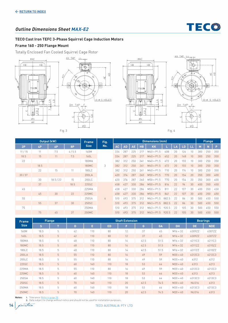
Outline Dimensions Sheet MAX-E2
TECO Cast Iron TEFC 3-Phase Squirrel Cage Induction Motors
Frame 160 - 250 Flange Mount
Totally Enclosed Fan Cooled Squirrel Cage Rotor
Notes: 1. Tolerance: Refer to page 30. 2. Data subject to change without notice and should not be used for installation purposes.
Output (kW) Frame
Size
Fig.
No.
Dimensions (mm) Flange
2P 4P 6P 8P AC AD AE HB KK L LA LD LL M N P
11 / 15 11 7.5 4 / 5.5 160M
3
334 287 225 217 M40 × P1.5 608 20 126 10 300 250 350
18.5 15 11 7.5 160L 334 287 225 217 M40 × P1.5 652 20 148 10 300 250 350
22 180MA 382 312 250 241 M40 × P1.5 672 20 155 10 300 250 350
18.5 180MC 382 312 250 241 M40 × P1.5 672 20 155 10 300 250 350
22 15 11 180LC 382 312 250 241 M40 × P1.5 710 20 174 10 300 250 350
30 / 37 200LA 420 374 287 260 M50 × P1.5 770 20 154 20 350 300 400
30 18.5 / 22 15 200LC 420 374 287 260 M50 × P1.5 770 20 154 20 350 300 400
37 18.5 225SC
4
458 427 330 286 M50 × P1.5 816 22 94 30 400 350 450
45 225MA 458 427 330 286 M50 × P1.5 811 22 107 30 400 350 450
45 30 22 225MC 458 427 330 286 M50 × P1.5 841 22 107 30 400 350 450
55 250SA 510 493 375 312 M63 × P1.5 882.5 22 86 30 500 450 550
55 37 30 250SC 510 493 375 312 M63 × P1.5 882.5 22 86 30 500 450 550
75 250MA 510 493 375 312 M63 × P1.5 920.5 22 105 30 500 450 550
75 45 37 250MC 510 493 375 312 M63 × P1.5 920.5 22 105 30 500 450 550
Frame
Size
Flange Shaft Extension Bearings
S T D E ED F G GA DH DE NDE
160M 18.5 5 42 110 80 12 37 45 M16 × 32 6309ZZ 6307ZZ
160L 18.5 5 42 110 80 12 37 45 M16 × 32 6309ZZ 6307ZZ
180MA 18.5 5 48 110 80 14 42.5 51.5 M16 × 32 6211C3 6211C3
180MC 18.5 5 48 110 80 14 42.5 51.5 M16 × 32 6311ZZ 6310ZZ
180LC 18.5 5 48 110 80 14 42.5 51.5 M16 × 32 6311ZZ 6310ZZ
200LA 18.5 5 55 110 80 16 49 59 M20 × 40 6312C3 6212C3
200LC 18.5 5 55 110 80 16 49 59 M20 × 40 6312 6212
225SC 18.5 5 60 140 110 18 53 64 M20 × 40 6313 6213
225MA 18.5 5 55 110 80 16 49 59 M20 × 40 6312C3 6212C3
225MC 18.5 5 60 140 110 18 53 64 M20 × 40 6313 6213
250SA 18.5 5 60 140 110 18 53 64 M20 × 40 6313C3 6213C3
250SC 18.5 5 70 140 110 20 62.5 74.5 M20 × 40 NU316 6313
250MA 18.5 5 60 140 110 18 53 64 M20 × 40 6313C3 6213C3
250MC 18.5 5 70 140 110 20 62.5 74.5 M20 × 40 NU316 6313
Fig. 3 Fig. 4
TECO AUSTRALIA PTY LTDfourteen14

RETURN TO INDEX
Outline Dimensions Sheet MAX-E2
TECO Cast Iron TEFC 3-Phase Squirrel Cage Induction Motors
Frame 63 - 200 Foot and Flange Mount
Totally Enclosed Fan Cooled Squirrel Cage Rotor
Output (kW) Frame
Size
Fig.
No.
Dimensions (mm)
2P 4P 6P 8P A AA AB AD AE B BB C H HA HC HD HE K KK
0.18 0.18 - - 632
100 28 120 123 97 80 100 69 63 8 135 - 10 7 M20 × P1.5
0.37 / 0.55 0.37 0.18 - 71 112 35.5 140 148 110 90 115 72 71 8 152 - 35 7 M20 × P1.5
0.75 / 1.1 0.55 / 0.75 0.37 / 0.55 0.18 80 1 125 35.5 155 179 130 100 130 50 80 9 180 - 13 10 M25 × P1.5
1.5 1.1 0.75 0.37 90S
2
140 35.5 170 192 143 100 130 95 90 10 190 - 23 10 M25 × P1.5
2.2 1.5 1.1 0.55 90L 140 35.5 170 192 143 125 150 95 90 10 190 - 23 10 M25 × P1.5
3 2.2 / 3 1.5 0.75 / 1.1 100L 160 45 195 202 153 140 175 103 100 12.5 - 243 33 12 M25 × P1.5
4 4 2.2 1.5 112M 190 45 224 211 162 140 175 110 112 14 - 265 45 12 M25 × P1.5
5.5 / 7.5 5.5 3 2.2 132S 216 45 250 249 187 140 175 139 132 16 - 310 58 12 M40 × P1.5
- 7.5 4 / 5.5 3 132M 216 45 250 249 187 178 212 139 132 16 - 310 58 12 M40 × P1.5
11 / 15 11 7.5 4 / 5.5 160M
3
254 50 300 287 225 210 250 108 160 18 - 377 83 14.5 M40 × P1.5
18.5 15 11 7.5 160L 254 50 300 287 225 254 300 108 160 18 - 377 83 14.5 M40 × P1.5
22 - - - 180MA 279 75 355 312 250 241 297 121 180 20 - 421 103 14.5 M40 × P1.5
- 18.5 - - 180MC 279 75 355 312 250 241 297 121 180 20 - 421 103 14.5 M40 x P1.5
- 22 15 11 180LC 279 75 355 312 250 279 335 121 180 20 - 421 103 14.5 M40 × P1.5
30/37 - - - 200LA 318 80 400 374 287 305 365 133 200 25 - 469 88 18.5 M50 × P1.5
- 30 18.5 / 22 15 200LC 318 80 400 374 287 305 365 133 200 25 - 469 88 18.5 M50 × P1.5
Notes: 1. Tolerance: Refer to page 30. 2. Lifting lugs not provided on frames D90 and smaller. 3. Data subject to change without notice and should not be used for installation purposes.
Frame
Size
Flange Shaft Extension Bearings
LA LE L M N P S T D E ED F G GA DH DE NDE
63 12 76 248 115 95 140 10 3 11 23 10 4 8.5 12.5 M4 × 8 6201ZZ 6201ZZ
71 12 86 278 130 110 160 10 3.5 14 30 14 5 11 16 M5 × 10 6202ZZ 6202ZZ
80 12 92.5 282.5 165 130 200 12 3.5 19 40 25 6 15.5 21.5 M6 × 12 6204ZZ 6204ZZ
90S 12 101.5 346.5 165 130 200 12 3.5 24 50 32 8 20 27 M8 × 16 6205ZZ 6205ZZ
90L 12 101.5 371.5 165 130 200 12 3.5 24 50 32 8 20 27 M8 × 16 6205ZZ 6205ZZ
100L 16 112 414.5 215 180 250 14.5 4 28 60 40 8 24 31 M10 × 20 6206ZZ 6305ZZ
112M 16 121.5 431.5 215 180 250 14.5 4 28 60 40 8 24 31 M10 × 20 6306ZZ 6306ZZ
132S 20 145 504 265 230 300 14.5 4 38 80 56 10 33 41 M12 × 24 6308ZZ 6306ZZ
132M 20 145 542 265 230 300 14.5 4 38 80 56 10 33 41 M12 × 24 6308ZZ 6306ZZ
160M 20 180 608 300 250 350 18.5 5 42 110 80 12 37 45 M16 × 32 6309ZZ 6307ZZ
160L 20 180 652 300 250 350 18.5 5 42 110 80 12 37 45 M16 × 32 6309ZZ 6307ZZ
180MA 20 200 672 300 250 350 18.5 5 48 110 80 14 42.5 51.5 M16 × 32 (6211C3) (6211C3)
180MC 20 200 672 300 250 350 18.5 5 48 110 80 14 42.5 51.5 M16 × 32 6311ZZ 6310ZZ
180LC 20 200 710 300 250 350 18.5 5 48 110 80 14 42.5 51.5 M16 × 32 6311ZZ 6310ZZ
200LA 20 222 770 350 300 400 18.5 5 55 110 80 16 49 59 M20 × 40 (6312C3) (6212C3)
200LC 20 222 770 350 300 400 18.5 5 55 160 80 16 49 59 M20 × 40 6312C3 6212C3
Fig. 1 Fig. 2 Fig. 3
fifteen 15TECO AUSTRALIA PTY LTD
RETURN TO INDEX
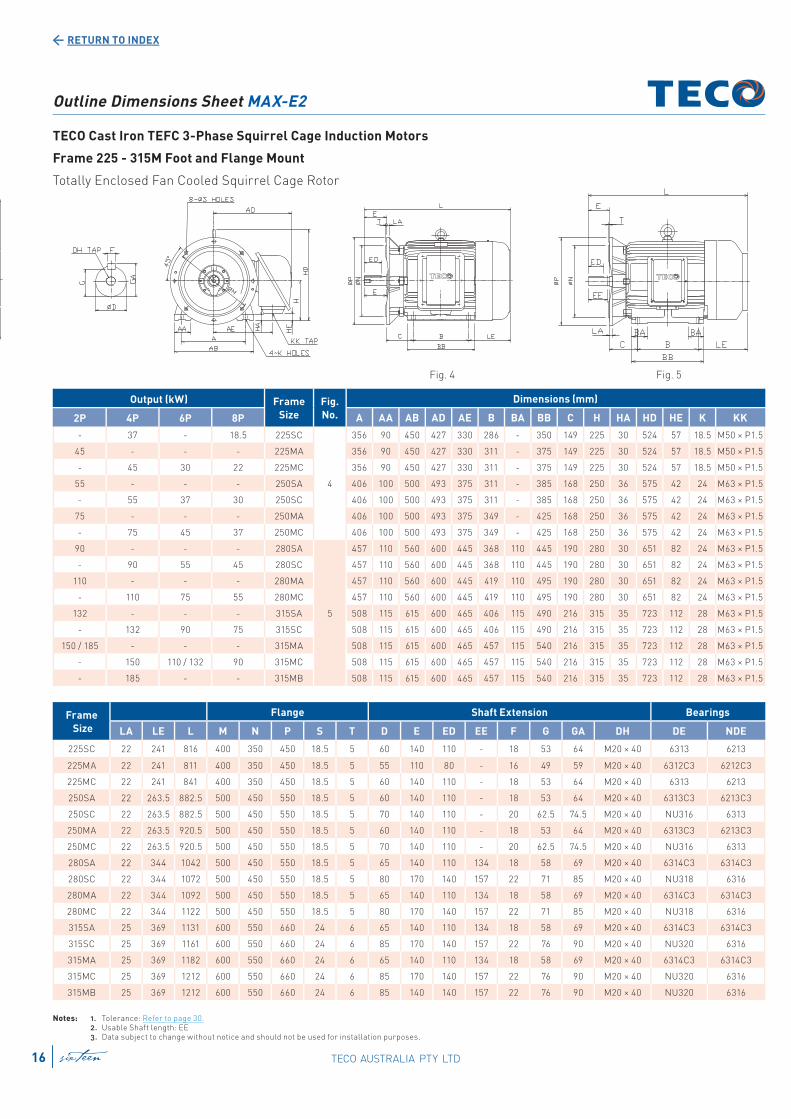
Fig. 4 Fig. 5
Outline Dimensions Sheet MAX-E2
TECO Cast Iron TEFC 3-Phase Squirrel Cage Induction Motors
Frame 225 - 315M Foot and Flange Mount
Totally Enclosed Fan Cooled Squirrel Cage Rotor
Output (kW) Frame
Size
Fig.
No.
Dimensions (mm)
2P 4P 6P 8P A AA AB AD AE B BA BB C H HA HD HE K KK
- 37 - 18.5 225SC
4
356 90 450 427 330 286 - 350 149 225 30 524 57 18.5 M50 × P1.5
45 - - - 225MA 356 90 450 427 330 311 - 375 149 225 30 524 57 18.5 M50 × P1.5
- 45 30 22 225MC 356 90 450 427 330 311 - 375 149 225 30 524 57 18.5 M50 × P1.5
55 - - - 250SA 406 100 500 493 375 311 - 385 168 250 36 575 42 24 M63 × P1.5
- 55 37 30 250SC 406 100 500 493 375 311 - 385 168 250 36 575 42 24 M63 × P1.5
75 - - - 250MA 406 100 500 493 375 349 - 425 168 250 36 575 42 24 M63 × P1.5
- 75 45 37 250MC 406 100 500 493 375 349 - 425 168 250 36 575 42 24 M63 × P1.5
90 - - - 280SA
5
457 110 560 600 445 368 110 445 190 280 30 651 82 24 M63 × P1.5
- 90 55 45 280SC 457 110 560 600 445 368 110 445 190 280 30 651 82 24 M63 × P1.5
110 - - - 280MA 457 110 560 600 445 419 110 495 190 280 30 651 82 24 M63 × P1.5
- 110 75 55 280MC 457 110 560 600 445 419 110 495 190 280 30 651 82 24 M63 × P1.5
132 - - - 315SA 508 115 615 600 465 406 115 490 216 315 35 723 112 28 M63 × P1.5
- 132 90 75 315SC 508 115 615 600 465 406 115 490 216 315 35 723 112 28 M63 × P1.5
150 / 185 - - - 315MA 508 115 615 600 465 457 115 540 216 315 35 723 112 28 M63 × P1.5
- 150 110 / 132 90 315MC 508 115 615 600 465 457 115 540 216 315 35 723 112 28 M63 × P1.5
- 185 - - 315MB 508 115 615 600 465 457 115 540 216 315 35 723 112 28 M63 × P1.5
Notes: 1. Tolerance: Refer to page 30. 2. Usable Shaft length: EE 3. Data subject to change without notice and should not be used for installation purposes.
Frame
Size
Flange Shaft Extension Bearings
LA LE L M N P S T D E ED EE F G GA DH DE NDE
225SC 22 241 816 400 350 450 18.5 5 60 140 110 - 18 53 64 M20 × 40 6313 6213
225MA 22 241 811 400 350 450 18.5 5 55 110 80 - 16 49 59 M20 × 40 6312C3 6212C3
225MC 22 241 841 400 350 450 18.5 5 60 140 110 - 18 53 64 M20 × 40 6313 6213
250SA 22 263.5 882.5 500 450 550 18.5 5 60 140 110 - 18 53 64 M20 × 40 6313C3 6213C3
250SC 22 263.5 882.5 500 450 550 18.5 5 70 140 110 - 20 62.5 74.5 M20 × 40 NU316 6313
250MA 22 263.5 920.5 500 450 550 18.5 5 60 140 110 - 18 53 64 M20 × 40 6313C3 6213C3
250MC 22 263.5 920.5 500 450 550 18.5 5 70 140 110 - 20 62.5 74.5 M20 × 40 NU316 6313
280SA 22 344 1042 500 450 550 18.5 5 65 140 110 134 18 58 69 M20 × 40 6314C3 6314C3
280SC 22 344 1072 500 450 550 18.5 5 80 170 140 157 22 71 85 M20 × 40 NU318 6316
280MA 22 344 1092 500 450 550 18.5 5 65 140 110 134 18 58 69 M20 × 40 6314C3 6314C3
280MC 22 344 1122 500 450 550 18.5 5 80 170 140 157 22 71 85 M20 × 40 NU318 6316
315SA 25 369 1131 600 550 660 24 6 65 140 110 134 18 58 69 M20 × 40 6314C3 6314C3
315SC 25 369 1161 600 550 660 24 6 85 170 140 157 22 76 90 M20 × 40 NU320 6316
315MA 25 369 1182 600 550 660 24 6 65 140 110 134 18 58 69 M20 × 40 6314C3 6314C3
315MC 25 369 1212 600 550 660 24 6 85 170 140 157 22 76 90 M20 × 40 NU320 6316
315MB 25 369 1212 600 550 660 24 6 85 140 140 157 22 76 90 M20 × 40 NU320 6316
TECO AUSTRALIA PTY LTDsixteen16
RETURN TO INDEX
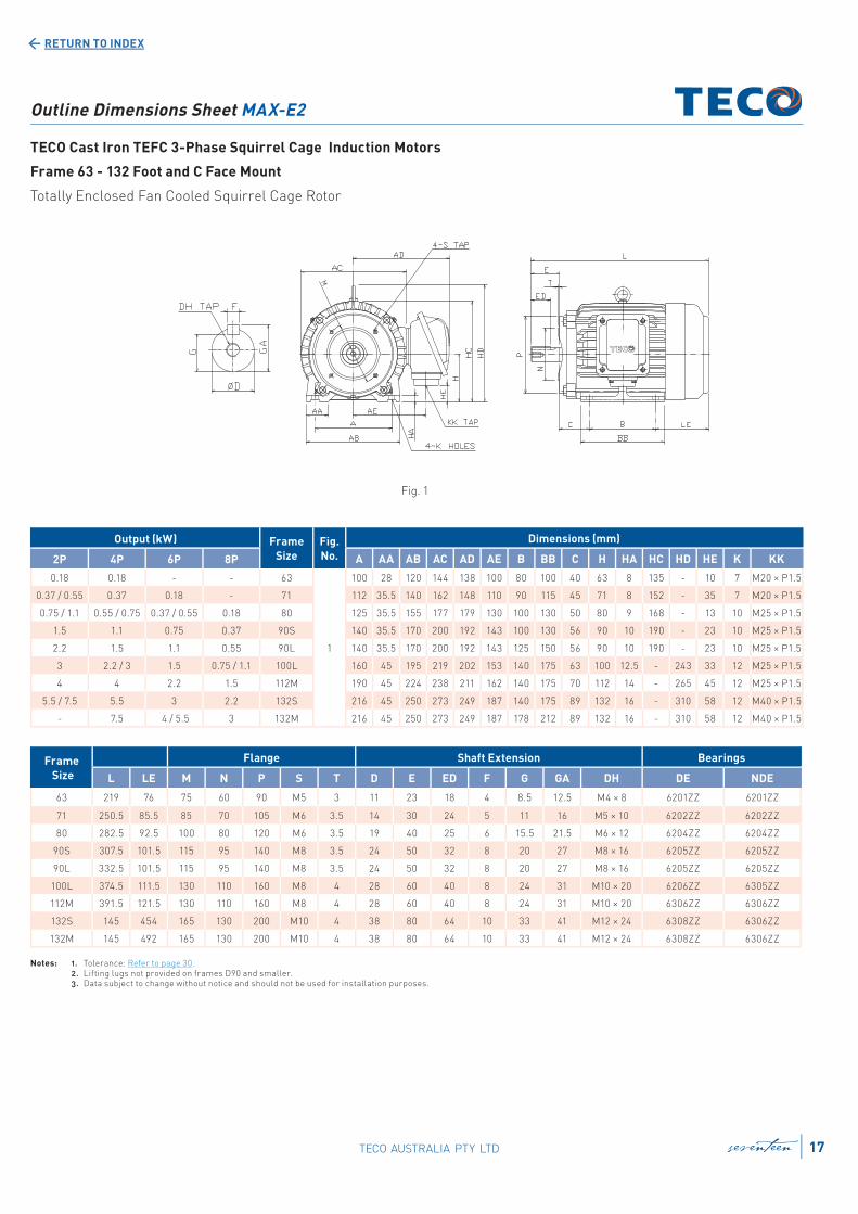
Outline Dimensions Sheet MAX-E2
TECO Cast Iron TEFC 3-Phase Squirrel Cage Induction Motors
Frame 63 - 132 Foot and C Face Mount
Totally Enclosed Fan Cooled Squirrel Cage Rotor
Frame
Size
Flange Shaft Extension Bearings
L LE M N P S T D E ED F G GA DH DE NDE
63 219 76 75 60 90 M5 3 11 23 18 4 8.5 12.5 M4 × 8 6201ZZ 6201ZZ
71 250.5 85.5 85 70 105 M6 3.5 14 30 24 5 11 16 M5 × 10 6202ZZ 6202ZZ
80 282.5 92.5 100 80 120 M6 3.5 19 40 25 6 15.5 21.5 M6 × 12 6204ZZ 6204ZZ
90S 307.5 101.5 115 95 140 M8 3.5 24 50 32 8 20 27 M8 × 16 6205ZZ 6205ZZ
90L 332.5 101.5 115 95 140 M8 3.5 24 50 32 8 20 27 M8 × 16 6205ZZ 6205ZZ
100L 374.5 111.5 130 110 160 M8 4 28 60 40 8 24 31 M10 × 20 6206ZZ 6305ZZ
112M 391.5 121.5 130 110 160 M8 4 28 60 40 8 24 31 M10 × 20 6306ZZ 6306ZZ
132S 145 454 165 130 200 M10 4 38 80 64 10 33 41 M12 × 24 6308ZZ 6306ZZ
132M 145 492 165 130 200 M10 4 38 80 64 10 33 41 M12 × 24 6308ZZ 6306ZZ
Output (kW) Frame
Size
Fig.
No.
Dimensions (mm)
2P 4P 6P 8P A AA AB AC AD AE B BB C H HA HC HD HE K KK
0.18 0.18 - - 63
1
100 28 120 144 138 100 80 100 40 63 8 135 - 10 7 M20 × P1.5
0.37 / 0.55 0.37 0.18 - 71 112 35.5 140 162 148 110 90 115 45 71 8 152 - 35 7 M20 × P1.5
0.75 / 1.1 0.55 / 0.75 0.37 / 0.55 0.18 80 125 35.5 155 177 179 130 100 130 50 80 9 168 - 13 10 M25 × P1.5
1.5 1.1 0.75 0.37 90S 140 35.5 170 200 192 143 100 130 56 90 10 190 - 23 10 M25 × P1.5
2.2 1.5 1.1 0.55 90L 140 35.5 170 200 192 143 125 150 56 90 10 190 - 23 10 M25 × P1.5
3 2.2 / 3 1.5 0.75 / 1.1 100L 160 45 195 219 202 153 140 175 63 100 12.5 - 243 33 12 M25 × P1.5
4 4 2.2 1.5 112M 190 45 224 238 211 162 140 175 70 112 14 - 265 45 12 M25 × P1.5
5.5 / 7.5 5.5 3 2.2 132S 216 45 250 273 249 187 140 175 89 132 16 - 310 58 12 M40 × P1.5
- 7.5 4 / 5.5 3 132M 216 45 250 273 249 187 178 212 89 132 16 - 310 58 12 M40 × P1.5
Notes: 1. Tolerance: Refer to page 30. 2. Lifting lugs not provided on frames D90 and smaller. 3. Data subject to change without notice and should not be used for installation purposes.
Fig. 1
seventeen 17TECO AUSTRALIA PTY LTD
RETURN TO INDEX
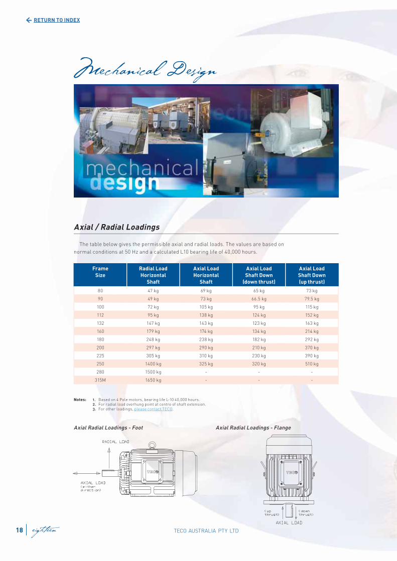
Axial / Radial Loadings
The table below gives the permissible axial and radial loads. The values are based on
normal conditions at 50 Hz and a calculated L10 bearing life of 40,000 hours.
Notes: 1. Based on 4 Pole motors, bearing life L-10 40,000 hours. 2. For radial load overhung point at centre of shaft extension. 3. For other loadings, please contact TECO.
Frame
Size
Radial Load
Horizontal
Shaft
Axial Load
Horizontal
Shaft
Axial Load
Shaft Down
(down thrust)
Axial Load
Shaft Down
(up thrust)
80 47 kg 69 kg 65 kg 73 kg
90 49 kg 73 kg 66.5 kg 79.5 kg
100 72 kg 105 kg 95 kg 115 kg
112 95 kg 138 kg 124 kg 152 kg
132 147 kg 143 kg 123 kg 163 kg
160 179 kg 174 kg 134 kg 214 kg
180 248 kg 238 kg 182 kg 292 kg
200 297 kg 290 kg 210 kg 370 kg
225 305 kg 310 kg 230 kg 390 kg
250 1400 kg 325 kg 320 kg 510 kg
280 1500 kg - - -
315M 1650 kg - - -
Axial Radial Loadings - Foot Axial Radial Loadings - Flange
TECO AUSTRALIA PTY LTD18 eighteen
RETURN TO INDEX
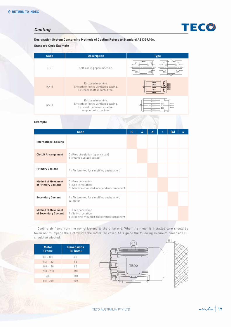
Cooling
Designation System Concerning Methods of Cooling Refers to Standard AS1359.106.
Standard Code Example
Example
Code Description Type
IC 01 Self-cooling open machine.
IC411
Enclosed machine.
Smooth or fi nned ventilated casing.
External shaft-mounted fan.
IC416
Enclosed machine.
Smooth or fi nned ventilated casing.
External motorized axial fan
supplied with machine.
Cooling air fl ows from the non-drive-end to the drive end. When the motor is installed care should be
taken not to impede the airfl ow into the motor fan cover. As a guide the following minimum dimension BL
should be adopted.
Motor
Frame
Dimensions
BL (mm)
80 - 100 60
112 - 132 85
160 - 180 85
200 - 250 110
280 140
315 - 355 180
Code IC 4 (A) 1 (A) 6
International Cooling
Circuit Arrangement 0 : Free circulation (open circuit)
4 : Frame surface cooled
Primary CoolantA : Air (omitted for simplifi ed designation)
Method of Movement
of Primary Coolant
0 : Free convection
1 : Self-circulation
6 : Machine-mounted independent component
Secondary Coolant A : Air (omitted for simplifi ed designation)
W : Water
Method of Movement
of Secondary Coolant
0 : Free convection
1 : Self-circulation
6 : Machine-mounted independent component
19TECO AUSTRALIA PTY LTD nineteen
RETURN TO INDEX
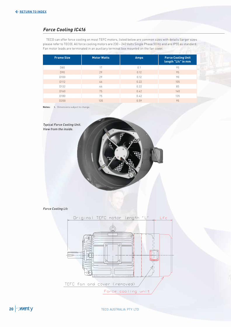
Typical Force Cooling Unit.
View from the inside.
Force Cooling Lfc
Force Cooling IC416
TECO can offer force cooling on most TEFC motors, listed below are common sizes with details (larger sizes
please refer to TECO). All force cooling motors are 230 ~ 240 Volts Single Phase 50 Hz and are IP55 as standard.
Fan motor leads are terminated in an auxiliary terminal box mounted on the fan cover.
Frame Size Motor Watts Amps Force Cooling Unit
length “Lfc” in mm
D80 17 0.1 95
D90 29 0.12 95
D100 29 0.12 90
D112 46 0.22 105
D132 46 0.22 85
D160 75 0.42 140
D180 75 0.42 135
D200 135 0.59 95
Notes: 1. Dimensions subject to change.
TECO AUSTRALIA PTY LTD20 twenty
RETURN TO INDEX
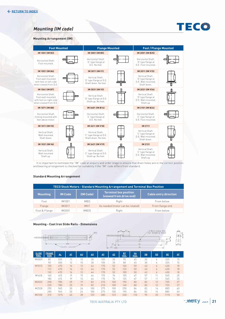
Mounting (IM code)
Mounting Arrangement (IM)
Foot Mounted Flange Mounted Foot / Flange Mounted
IM 1001 (IM B3) IM 3001 (IM B5) IM 2001 (IM B35)
Horizontal Shaft.
Foot mounted.
Horizontal Shaft.
‘D’ type fl ange at
D.E. No feet.
Horizontal Shaft.
‘D’ type fl ange at
D.E. Foot mounted.
IM 1051 (IM B6) IM 3011 (IM V1) IM 2011 (IM V15)
Horizontal Shaft.
Foot wall mounted
with feet on left-side
when viewed from D.E.
Vertical Shaft.
‘D’ type fl ange at D.E.
Shaft down. No feet.
Vertical Shaft.
‘D’ type fl ange at
D.E. Wall mounted.
Shaft down.
IM 1061 (IM B7) IM 3031 (IM V3) IM 2031 (IM V36)
Horizontal Shaft.
Foot wall mounted
with feet on right-side
when viewed from D.E.
Vertical Shaft.
‘D’ type fl ange at D.E.
Shaft up. No feet.
Vertical Shaft.
‘D’ type fl ange at
D.E. Wall mounted.
Shaft up.
IM 1071 (IM B8) IM 3601 (IM B14) IM 2101 (IM B34)
Horizontal Shaft.
Ceiling mounted with
feet above motor.
Horizontal Shaft.
‘C’ type fl ange at
D.E. No feet.
Horizontal Shaft.
‘C’ type fl ange at
D.E. Foot mounted.
IM 1011 (IM V5) IM 3611 (IM V18) IM 2111
Vertical Shaft.
Wall mounted.
Shaft down.
Vertical Shaft.
‘C’ type fl ange at D.E.
Shaft down. No feet.
Vertical Shaft.
‘C’ type fl ange at
D.E. Wall mounted.
Shaft down.
IM 1031 (IM V6) IM 3631 (IM V19) IM 2131
Vertical Shaft.
Wall mounted.
Shaft up.
Vertical Shaft.
‘C’ type fl ange at D.E.
Shaft up. No feet.
Vertical Shaft.
‘C’ type fl ange at
D.E. Wall mounted.
Shaft up.
It is important to nominate the “IM” code at enquiry and order stage to ensure that drain holes are in the correct position
and bearing arrangement is checked for suitability if the “IM” code differs from standard.
Standard Mounting Arrangement
Mounting - Cast Iron Slide Rails - Dimensions
TECO Stock Motors - Standard Mounting Arrangement and Terminal Box Position
Mounting IM Code (IM Code)Terminal box position
(viewed from drive end)Cable entry direction
Foot IM1001 IMB3 Right From below
Flange IM3011 IMV1 As needed (motor can be rotated) From fl ange end
Foot & Flange IM2001 IMB35 Right From below
SLIDERAIL
FRAME SIZE
AL AT AU AX AY AZBT
min.XA
max.XB XD XE XF
M0809 80 355 12 10 30 105 35 95 45 30 6 325 15
90 355 12 10 30 105 35 80 45 30 6 325 15
M1013 100 470 16 12 44 170 52 160 50 43 6 430 18
112 470 16 12 44 170 52 125 50 43 6 430 18
132 470 16 12 44 170 52 100 50 43 6 430 18
M1618 160 615 19 15 64 170 76 155 67 57 11 565 25
180 615 19 15 64 170 76 125 67 57 11 565 25
M2022 200 780 25 19 82 210 100 190 80 82 12 725 27
225 780 25 19 82 210 100 140 80 82 12 725 27
M2528 250 965 30 24 100 275 100 250 86 82 16 885 40
280 965 30 24 100 275 100 190 86 82 16 885 40
M3100 315 1215 40 38 125 380 123 330 110 95 20 1115 50
21TECO AUSTRALIA PTY LTD twenty one
RETURN TO INDEX
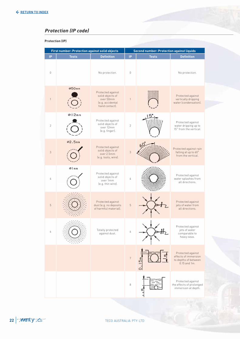
Protection (IP code)
Protection (IP)
First number: Protection against solid objects Second number: Protection against liquids
IP Tests Defi nition IP Tests Defi nition
0 No protection. 0 No protection.
1
Protected against
solid objects of
over 50mm
(e.g. accidental
hand contact).
1
Protected against
vertically dripping
water (condensation).
2
Protected against
solid objects of
over 12mm
(e.g. fi nger).
2
Protected against
water dripping up to
15˚ from the vertical.
3
Protected against
solid objects of
over 2.5mm
(e.g. tools, wire).
3
Protected against rain
falling at up to 60˚
from the vertical.
4
Protected against
solid objects of
over 1mm
(e.g. thin wire).
4
Protected against
water splashes from
all directions.
5
Protected against
dust (e.g. no deposits
of harmful material).
5
Protected against
jets of water from
all directions.
6Totally protected
against dust.6
Protected against
jets of water
comparable to
heavy seas.
7
Protected against
effects of immersion
to depths of between
0.15 and 1m.
8
Protected against
the effects of prolonged
immersion at depth.
TECO AUSTRALIA PTY LTD22 twenty two
RETETURNUR TOO ININDEXD
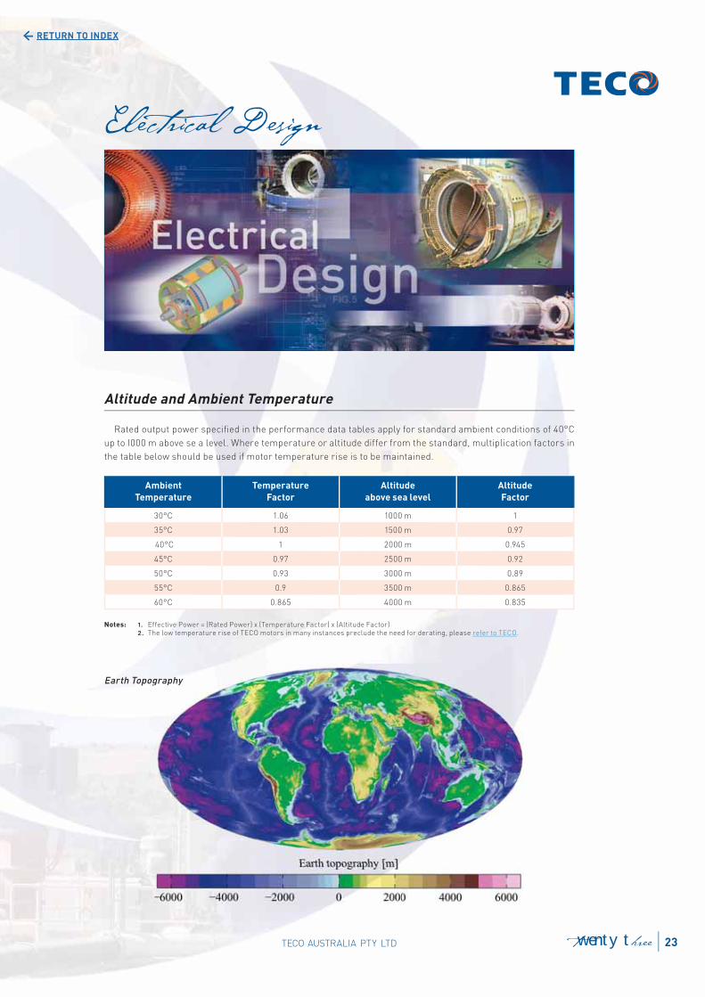
Altitude and Ambient Temperature
Rated output power specifi ed in the performance data tables apply for standard ambient conditions of 40°C
up to I000 m above se a level. Where temperature or altitude differ from the standard, multiplication factors in
the table below should be used if motor temperature rise is to be maintained.
Earth Topography
Ambient
Temperature
Temperature
Factor
Altitude
above sea level
Altitude
Factor
30°C 1.06 1000 m 1
35°C 1.03 1500 m 0.97
40°C 1 2000 m 0.945
45°C 0.97 2500 m 0.92
50°C 0.93 3000 m 0.89
55°C 0.9 3500 m 0.865
60°C 0.865 4000 m 0.835
Notes: 1. Effective Power = (Rated Power) x (Temperature Factor) x (Altitude Factor) 2. The low temperature rise of TECO motors in many instances preclude the need for derating, please refer to TECO.
graphy
23TECO AUSTRALIA PTY LTD twenty three
RETURN TO INDEX
Anti-condensation heaters are used to prevent
the water accumulation caused by moisture
condensation inside the motor. These are fl exible
type elements and tied on the ends of the winding
to maintain the average temperature of the motor
above dew point. The heaters must be switched on
when the machine stops and switched off whilst
the machine is in operation. A prominent warning
label is fi tted with the appropriate rating of the
heaters nominated.
The space heater leads are normally terminated
to an auxiliary terminal box for safety reasons.
The normal supply of space heaters is single
phase 240V, other voltages can be supplied on
request.
Power Rating of Anti-Condensation Heaters
Heater length varies to suit diameter of end-winding.
Anti-Condensation Heaters (Optional)
Frame
Size
Power in
Watts
80 ~ 100 25
112 21
132 ~ 160 40
180 ~ 200 26
225 ~ 250 42
280 54
315M 99
315A 200
355 250
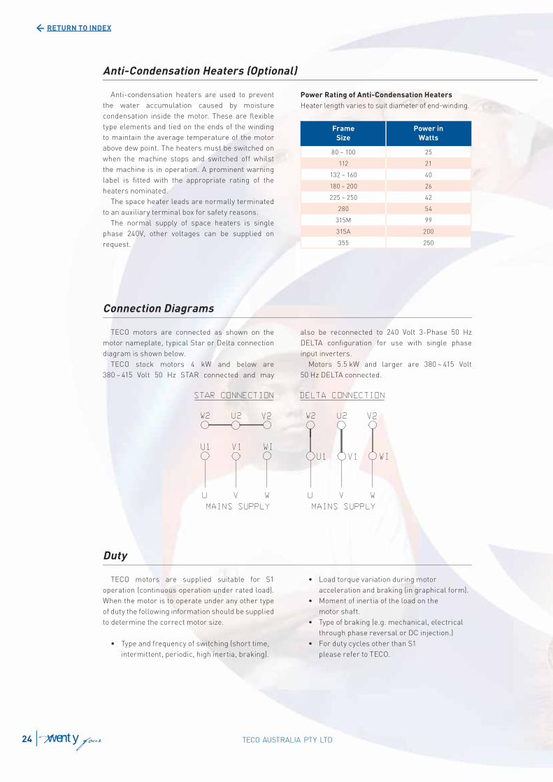
TECO motors are connected as shown on the
motor nameplate, typical Star or Delta connection
diagram is shown below.
TECO stock motors 4 kW and below are
380 ~ 415 Volt 50 Hz STAR connected and may
also be reconnected to 240 Volt 3-Phase 50 Hz
DELTA confi guration for use with single phase
input inverters.
Motors 5.5 kW and larger are 380 ~ 415 Volt
50 Hz DELTA connected.
Connection Diagrams
TECO motors are supplied suitable for S1
operation (continuous operation under rated load).
When the motor is to operate under any other type
of duty the following information should be supplied
to determine the correct motor size.
• Type and frequency of switching (short time,
intermittent, periodic, high inertia, braking).
• Load torque variation during motor
acceleration and braking (in graphical form).
• Moment of inertia of the load on the
motor shaft.
• Type of braking (e.g. mechanical, electrical
through phase reversal or DC injection.)
• For duty cycles other than S1
please refer to TECO.
Duty
TECO AUSTRALIA PTY LTD24 twenty four
RETURN TO INDEX
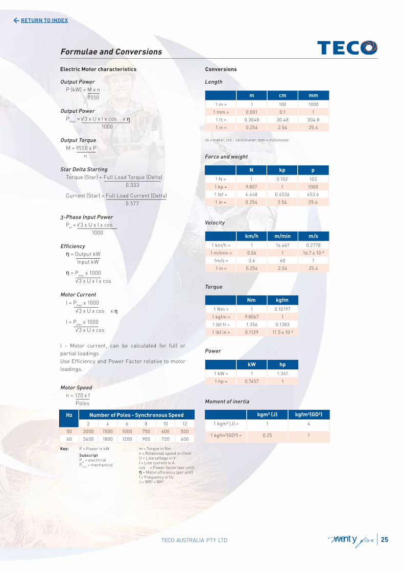
Formulae and Conversions
Electric Motor characteristics Conversions
Output Power
P (kW) = M x n
9550
Output Power
Pmec
= √3 x U x I x cos x
1000
Output Torque
M = 9550 x P
n
Star Delta Starting
Torque (Star) = Full Load Torque (Delta)
0.333
Current (Star) = Full Load Current (Delta)
0.577
3-Phase Input Power
Pel = √3 x U x I x cos
1000
Effi ciency
= Output kW
Input kW
= Pmec
x 1000
√3 x U x I x cos
Motor Current
I = Pmec
x 1000
√3 x U x cos x
I = Pelec
x 1000
√3 x U x cos
I - Motor current, can be calculated for full or
partial loadings.
Use Effi ciency and Power Factor relative to motor
loadings.
Motor Speed
n = 120 x f
Poles
Length
Force and weight
Velocity
Torque
Power
Moment of inertia
m cm mm
1 m = 1 100 1000
1 mm = 0.001 0.1 1
1 ft = 0.3048 30.48 304.8
1 in = 0.254 2.54 25.4
m = meter, cm - centimeter, mm = millimeter
N kp p
1 N = 1 0.102 102
1 kp = 9.807 1 1000
1 lbf = 4.448 0.4536 453.6
1 in = 0.254 2.54 25.4
km/h m/min m/s
1 km/h = 1 16.667 0.2778
1 m/min = 0.06 1 16.7 x 10-³
1m/s = 3.6 60 1
1 in = 0.254 2.54 25.4
Nm kgfm
1 Nm = 1 0.10197
1 kgfm = 9.8067 1
1 lbf.ft = 1.356 0.1383
1 lbf.in = 0.1129 11.5 x 10-³
kW hp
1 kW = 1 1.341
1 hp = 0.7457 1
kgm² (J) kgfm²(GD²)
1 kgm² (J) = 1 4
1 kgfm²(GD²) = 0.25 1
Key: P = Power in kW
Subscript P
el = electrical
Pmec
= mechanical
m = Torque in Nm n = Rotational speed in r/minU = Line voltage in VI = Line current in Acos = Power factor (per unit)
= Motor effi ciency (per unit)f = Frequency in HzJ = WR2 = WK2
Hz Number of Poles - Synchronous Speed
2 4 6 8 10 12
50 3000 1500 1000 750 600 500
60 3600 1800 1200 900 720 600
25TECO AUSTRALIA PTY LTD twenty fi ve
RETURN TO INDEX
0
100
200
300
400
0 20 40 60 80 100
% Synchronous Speed
0
200
400
600
800
% F
ull
Lo
ad
Cu
rre
nt
%
%
Pull-up Torque
Pull out or Breakdown torque
Full Load Torque
Full Load Current
Locked Rotor or Starting Torque
Locked Rotor or Starting Current
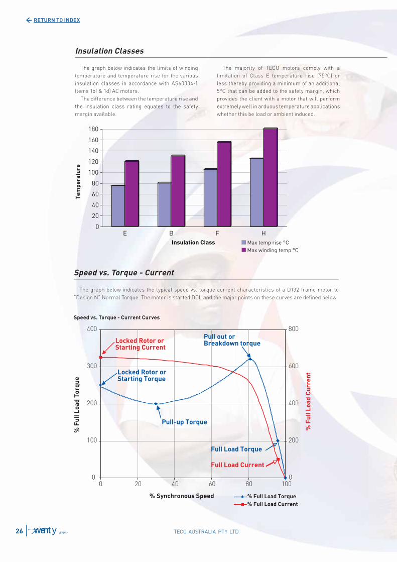
Speed vs. Torque - Current
The graph below indicates the typical speed vs. torque current characteristics of a D132 frame motor to
“Design N” Normal Torque. The motor is started DOL and the major points on these curves are defi ned below.
Speed vs. Torque - Current Curves
% Full Load Torque
% Full Load Current
% F
ull
Lo
ad
To
rqu
e
The graph below indicates the limits of winding
temperature and temperature rise for the various
insulation classes in accordance with AS60034-1
Items 1b) & 1d) AC motors.
The difference between the temperature rise and
the insulation class rating equates to the safety
margin available.
The majority of TECO motors comply with a
limitation of Class E temperature rise (75°C) or
less thereby providing a minimum of an additional
5°C that can be added to the safety margin, which
provides the client with a motor that will perform
extremely well in arduous temperature applications
whether this be load or ambient induced.
Insulation Classes
TECO AUSTRALIA PTY LTD26 twenty six
RETURN TO INDEX
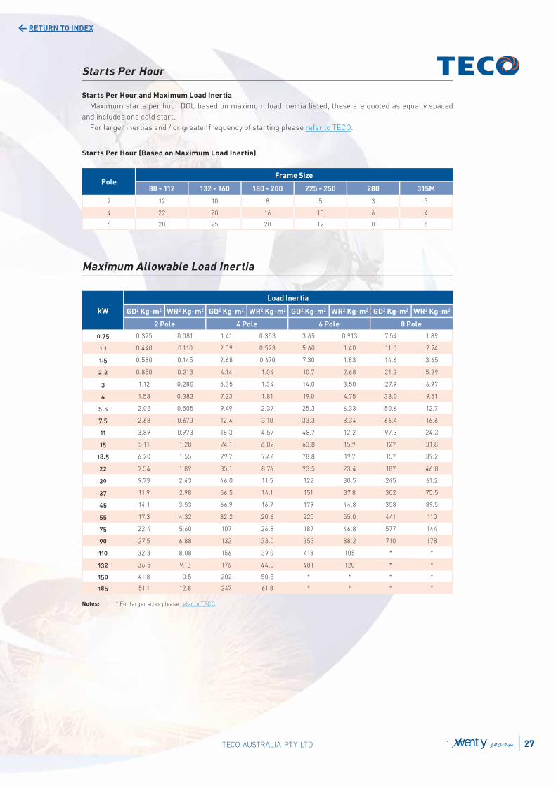
Starts Per Hour
Starts Per Hour and Maximum Load Inertia
Maximum starts per hour DOL based on maximum load inertia listed, these are quoted as equally spaced
and includes one cold start.
For larger inertias and / or greater frequency of starting please refer to TECO.
Starts Per Hour (Based on Maximum Load Inertia)
PoleFrame Size
80 - 112 132 - 160 180 - 200 225 - 250 280 315M
2 12 10 8 5 3 3
4 22 20 16 10 6 4
6 28 25 20 12 8 6
Maximum Allowable Load Inertia
kW
Load Inertia
GD2 Kg-m2 WR2 Kg-m2 GD2 Kg-m2 WR2 Kg-m2 GD2 Kg-m2 WR2 Kg-m2 GD2 Kg-m2 WR2 Kg-m2
2 Pole 4 Pole 6 Pole 8 Pole
0.75 0.325 0.081 1.41 0.353 3.65 0.913 7.54 1.89
1.1 0.440 0.110 2.09 0.523 5.60 1.40 11.0 2.74
1.5 0.580 0.145 2.68 0.670 7.30 1.83 14.6 3.65
2.2 0.850 0.213 4.14 1.04 10.7 2.68 21.2 5.29
3 1.12 0.280 5.35 1.34 14.0 3.50 27.9 6.97
4 1.53 0.383 7.23 1.81 19.0 4.75 38.0 9.51
5.5 2.02 0.505 9.49 2.37 25.3 6.33 50.6 12.7
7.5 2.68 0.670 12.4 3.10 33.3 8.34 66.4 16.6
11 3.89 0.973 18.3 4.57 48.7 12.2 97.3 24.3
15 5.11 1.28 24.1 6.02 63.8 15.9 127 31.8
18.5 6.20 1.55 29.7 7.42 78.8 19.7 157 39.2
22 7.54 1.89 35.1 8.76 93.5 23.4 187 46.8
30 9.73 2.43 46.0 11.5 122 30.5 245 61.2
37 11.9 2.98 56.5 14.1 151 37.8 302 75.5
45 14.1 3.53 66.9 16.7 179 44.8 358 89.5
55 17.3 4.32 82.2 20.6 220 55.0 441 110
75 22.4 5.60 107 26.8 187 46.8 577 144
90 27.5 6.88 132 33.0 353 88.2 710 178
110 32.3 8.08 156 39.0 418 105 * *
132 36.5 9.13 176 44.0 481 120 * *
150 41.8 10.5 202 50.5 * * * *
185 51.1 12.8 247 61.8 * * * *
Notes: * For larger sizes please refer to TECO.
27TECO AUSTRALIA PTY LTD twenty seven
RETURN TO INDEX
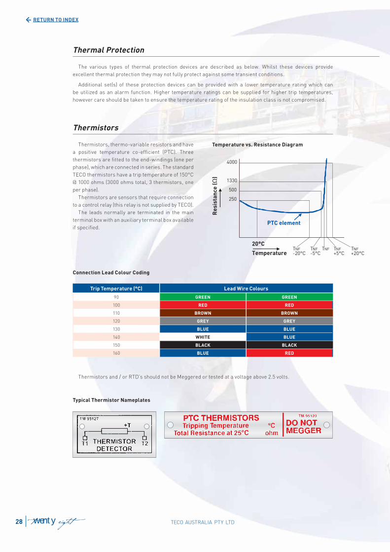
Thermistors, thermo-variable resistors and have
a positive temperature co-effi cient (PTC). Three
thermistors are fi tted to the end-windings (one per
phase), which are connected in series. The standard
TECO thermistors have a trip temperature of 150°C
@ 1000 ohms (3000 ohms total, 3 thermistors, one
per phase).
Thermistors are sensors that require connection
to a control relay (this relay is not supplied by TECO).
The leads normally are terminated in the main
terminal box with an auxiliary terminal box available
if specifi ed.
Connection Lead Colour Coding
Typical Thermistor Nameplates
Temperature vs. Resistance Diagram
Thermal Protection
The various types of thermal protection devices are described as below. Whilst these devices provide
excellent thermal protection they may not fully protect against some transient conditions.
Additional set(s) of these protection devices can be provided with a lower temperature rating which can
be utilized as an alarm function. Higher temperature ratings can be supplied for higher trip temperatures,
however care should be taken to ensure the temperature rating of the insulation class is not compromised.
Thermistors
Ω
Trip Temperature (°C) Lead Wire Colours
90 GREEN GREEN
100 RED RED
110 BROWN BROWN
120 GREY GREY
130 BLUE BLUE
140 WHITE BLUE
150 BLACK BLACK
160 BLUE RED
Thermistors and / or RTD’s should not be Meggered or tested at a voltage above 2.5 volts.
TECO AUSTRALIA PTY LTD28 twenty eight
RETURN TO INDEX
A (white)
B (red)
B (red)
• Winding RTDs can be provided within the windings, one per phase or more as required.
• Bearing RTDs can be provided if required. The RTD element is located in a stainless steel
metal probe and is mounted within a bearing thermowell.
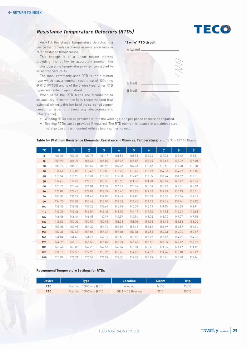
Table for Platinum Resistance Elements (Resistance in Ohms vs. Temperature) e.g. 19°C = 107.40 Ohms
Recommend Temperature Settings for RTDs
An RTD, Resistance Temperature Detector, is a
device that provides a change in resistance value in
relationship to temperature.
This change is of a linear nature thereby
providing the ability to accurately monitor the
motor operating temperatures when connected to
an appropriate relay.
The most commonly used RTD is the platinum
type which has a nominal resistance of 100ohms
@ 0°C (PT100) and is of the 3 wire type (other RTD
types available on application).
When fi tted the RTD leads are terminated to
an auxiliary terminal box (it is recommended that
external wiring to this box be of the screened copper
conductor type to prevent any electromagnetic
interference).
“3 wire” RTD circuit
Resistance Temperature Detectors (RTDs)
°C 0 1 2 3 4 5 6 7 8 9
0 100.00 100.39 100.78 101.17 101.56 101.95 102.34 102.73 103.12 103.51
10 103.90 104.29 104.68 105.07 105.46 105.85 106.24 106.63 107.02 107.40
20 107.79 108.18 108.57 108.96 109.35 109.73 110.12 110.51 110.90 111.28
30 111.67 112.06 112.45 112.83 113.22 113.61 113.99 114.38 114.77 115.15
40 115.54 115.93 116.31 116.70 117.08 117.47 117.85 118.24 118.62 119.01
50 119.40 119.78 120.16 120.55 120.93 121.32 121.70 122.09 122.47 122.86
60 123.24 123.62 124.01 124.39 124.77 125.16 125.54 125.92 126.31 126.69
70 127.07 127.45 127.84 128.22 128.60 128.98 129.37 129.75 130.13 130.51
80 130.89 131.27 131.66 132.04 132.42 132.80 133.18 133.56 133.94 134.32
90 134.70 135.08 135.46 135.84 136.22 136.60 136.98 137.36 137.74 138.12
100 138.50 138.88 139.26 139.64 140.02 140.39 140.77 141.15 141.53 141.91
110 142.29 142.66 143.04 143.42 143.80 144.17 144.55 144.93 145.31 145.68
120 146.06 146.44 146.81 147.19 147.57 147.94 148.32 148.70 149.07 149.45
130 149.82 150.20 150.57 150.95 151.33 151.70 152.08 152.45 152.83 153.20
140 153.58 153.95 154.32 154.70 155.07 155.45 155.82 156.19 156.57 156.94
150 157.31 157.69 158.06 158.43 158.81 159.18 159.55 159.93 160.30 160.67
160 161.04 161.42 161.79 162.16 162.53 162.90 163.27 163.65 164.02 164.39
170 164.76 165.13 165.50 165.87 166.24 166.61 166.98 167.35 167.72 168.09
180 168.46 168.83 169.20 169.57 169.94 170.31 170.68 171.05 171.42 171.19
190 172.16 172.53 172.90 173.26 173.63 174.00 174.37 174.74 175.10 175.47
200 175.84 176.21 176.57 176.94 177.31 177.68 178.04 178.41 178.78 179.14
Device Type Location Alarm Trip
RTD Platinium 100 Ohms @ 0oC Winding 140
oC 150
oC
RTD Platinium 100 Ohms @ 0oC DE & NDE Bearing 95
oC 100
oC
29TECO AUSTRALIA PTY LTD twenty nine
RETURN TO INDEX
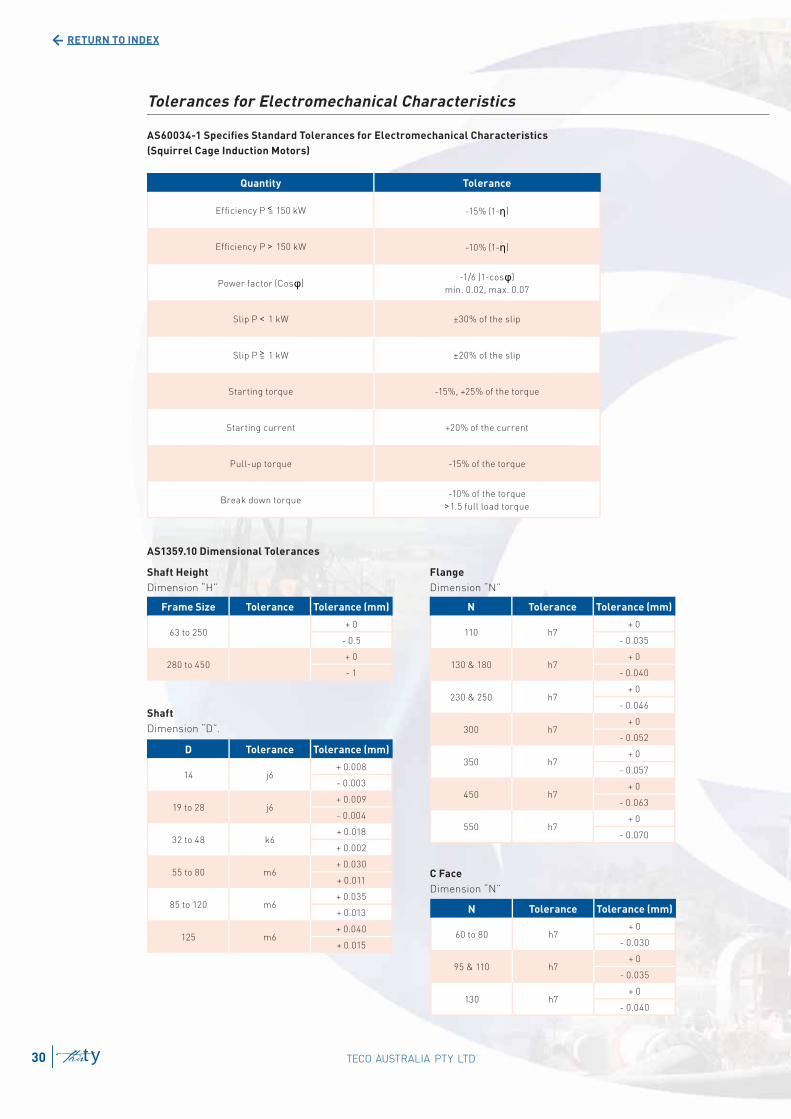
Tolerances for Electromechanical Characteristics
AS60034-1 Specifi es Standard Tolerances for Electromechanical Characteristics
(Squirrel Cage Induction Motors)
Quantity Tolerance
Effi ciency P < 150 kW -15% (1- )
Effi ciency P > 150 kW -10% (1- )
Power factor (Cos )-1/6 (1-cos )
min. 0.02, max. 0.07
Slip P < 1 kW ±30% of the slip
Slip P > 1 kW ±20% of the slip
Starting torque -15%, +25% of the torque
Starting current +20% of the current
Pull-up torque -15% of the torque
Break down torque-10% of the torque
>1.5 full load torque
=
=
AS1359.10 Dimensional Tolerances
Shaft Height
Dimension “H”
Shaft
Dimension “D”.
Flange
Dimension “N”
C Face
Dimension “N”
Frame Size Tolerance Tolerance (mm)
63 to 250+ 0
- 0.5
280 to 450+ 0
- 1
D Tolerance Tolerance (mm)
14 j6+ 0.008
- 0.003
19 to 28 j6+ 0.009
- 0.004
32 to 48 k6+ 0.018
+ 0.002
55 to 80 m6+ 0.030
+ 0.011
85 to 120 m6+ 0.035
+ 0.013
125 m6+ 0.040
+ 0.015
N Tolerance Tolerance (mm)
110 h7+ 0
- 0.035
130 & 180 h7+ 0
- 0.040
230 & 250 h7+ 0
- 0.046
300 h7+ 0
- 0.052
350 h7+ 0
- 0.057
450 h7+ 0
- 0.063
550 h7+ 0
- 0.070
N Tolerance Tolerance (mm)
60 to 80 h7+ 0
- 0.030
95 & 110 h7+ 0
- 0.035
130 h7+ 0
- 0.040
TECO AUSTRALIA PTY LTD30 thirty

RETETURNUR TOO ININDEXD
Variable Speed Drives (VVVF)
The output of Variable Voltage Variable Frequency (VVVF) Drives is not purely sinusoidal. This causes higher
voltage stresses within the windings and increases the losses, vibration, and noise of the motor. The Loadability
Curve and Maximum Safe Speed are as below, this graph should be used as a guide only. Further consultation
with TECO may be required for arduous critical speed and load duties.
Typical Motor Loadability Curve
For variable torque loads (centrifugal pumps and fans) for speeds between 5-50 Hz derating is not normally
required. Outside of this range please check with TECO for motor suitability.
Typical variable and constant torque load curves are shown below.
Speed vs. Torque Curves (assuming load torque @ 100% speed = motor full load torque)
Notes: 1. Installation: to follow the guidelines detailed in “AS60034-17:2006 Cage induction motors when fed from converters - Application guide” 2. Maximum safe operating speed to follow AS60034-1,Table 17
0
10
20
30
40
50
60
70
808
90
100
110
0 10 2000 30 4400 50 660 7700 8800 90 100 1110 120
%M
oto
rT
orq
ue
ue
ue
Continuouss operating region for standdard motor
Continuous operatiinngg rreeggiionon ffoorrmmoottoorrr fitted with Fan
Forced Cooling
Motor Constant ToTT rqrr ue rreeggiioonn Motor Constant Power regionn
FFreeqquueenncccyyyyyyy HHzzz
31TECO AUSTRALIA PTY LTD thirty one
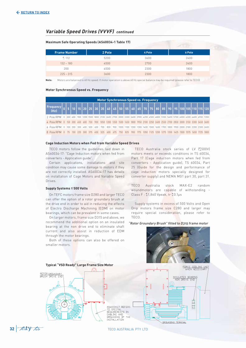
RETURN TO INDEX
Variable Speed Drives (VVVF) continued
Maximum Safe Operating Speeds (AS60034-1 Table 17)
Frame Number 2 Pole 4 Pole 6 Pole
< 112 5200 3600 2400
132 ~ 180 4500 2700 2400
200 4500 2300 1800
225 ~ 315 3600 2300 1800
Motor Synchronous Speed vs. Frequency
Cage Induction Motors when Fed from Variable Speed Drives
–
Motor Synchronous Speed vs. Frequency
Frequency
(Hz)0 5 10 15 20 25 30 35 40 45 50 55 60 65 70 75 80 85 90 95 100 105 110 115 120
2 Pole RPM 0 300 600 900 1200 1500 1800 2100 2400 2700 3000 3300 3600 3900 4200 4500 4800 5100 5400 5700 6000 6300 6600 6900 7200
4 Pole RPM 0 150 300 450 600 750 900 1050 1200 1350 1500 1650 1800 1950 2100 2250 2400 2550 2700 2850 3000 3150 3300 3450 3600
6 Pole RPM 0 100 200 300 400 500 600 700 800 900 1000 1100 1200 1300 1400 1500 1600 1700 1800 1900 2000 2100 2200 2300 2400
8 Pole RPM 0 75 150 225 300 375 450 525 600 675 750 825 900 975 1050 1125 1200 1275 1350 1425 1500 1575 1650 1725 1800
Note: Motors are balanced to 60 Hz speed. If motor operation is above 60 Hz special balance may be required (please refer to TECO).
Typical “VSD Ready” Large Frame Size Motor
TECO motors follow the guidelines laid down in
AS60034-17: “Cage Induction motors when fed from
converters - Application guide”.
Certain applications, installations and site
condition may cause some damage to motors if they
are not correctly installed. AS60034-17 has details
on installation of Cage Motors and Variable Speed
Drives.
Supply Systems 500 Volts
On TEFC motors frame size D280 and larger TECO
can offer the option of a rotor groundary brush at
the drive end in order to aid in reducing the effects
of Electro Discharge Machining (EDM) on motor
bearings, which can be prevalent in some cases.
On larger motors, frame size D315 and above, we
recommend the additional option on an insulated
bearing at the non drive end to eliminate shaft
current and also assist in reduction of EDM
through the motor bearings.
Both of these options can also be offered on
smaller motors.
TECO Australia stock series of LV (<500V)
motors meets or exceeds conditions in TS 60034,
Part 17 (Cage induction motors when fed from
converters - Application guide), TS 60034, Part
25 (Guide for the design and performance of
cage induction motors specially designed for
converter supply) and NEMA MG1 part 30, part 31.
TECO Australia stock MAX-E2 random
woundmotors are capable of withstanding -
Class F : <1,860 Vpeak, tr >0.1μs
Supply systems in excess of 500 Volts and Open
Drip motors frame size C280 and larger may
require special consideration, please refer to
TECO.
“Rotor Groundary Brush” fi tted to D315 frame motor
––
––
TECO AUSTRALIA PTY LTD32 thirty two
––
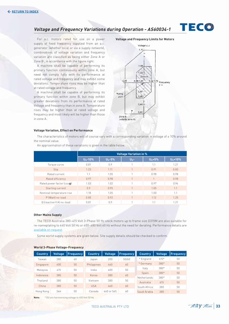
RETURN TO INDEX
For a.c. motors rated for use on a power
supply of fi xed frequency supplied from an a.c.
generator (whether local or via a supply network),
combinations of voltage variation and frequency
variation are classifi ed as being either Zone A or
Zone B , in accordance with the fi gure right.
A machine shall be capable of performing its
primary function continuously within zone A, but
need not comply fully with its performance at
rated voltage and frequency and may exhibit some
deviations. Temperature rises may be higher than
at rated voltage and frequency.
A machine shall be capable of performing its
primary function within zone B, but may exhibit
greater deviations from its performance at rated
Voltage and frequency than in zone A. Temperature
rises may be higher than at rated voltage and
frequency and most likely will be higher than those
in zone A.
Voltage and Frequency Limits for Motors
Voltage and Frequency Variations during Operation - AS60034-1
Voltage Variation, Effect on Performance
The characteristics of motors will of course vary with a corresponding variation in voltage of ± 10% around
the nominal value.
An approximation of these variations is given in the table below.
Voltage Variation in %
UN-10% UN-5% UN- UN+5% UN+10%
Torque curve 0.81 0.9 1 1.1 1.21
Slip 1.23 1.11 1 0.91 0.83
Rated current 1.1 1.05 1 0.98 0.98
Rated effi ciency 0.97 0.98 1 1 0.98
Rated power factor (cos ) 1.03 1.02 1 0.97 0.94
Starting current 0.9 0.95 1 1.05 1.1
Nominal temperature rise 1.18 1.05 1 1.00 1.1
P (Watt) no-load 0.85 0.92 1 1.12 1.25
Q (reactive V A) no-load 0.81 0.9 1 1.1 1.21
Other Mains Supply
The TECO Australia 380~415 Volt 3-Phase 50 Hz stock motors up to frame size D315M are also suitable for
re-nameplating to 440 Volt 50 Hz or 400~480 Volt 60 Hz without the need for derating. Performance details are
available on request.
Some world supply systems are given below. Site supply details should be checked to confi rm.
World 3-Phase Voltage-Frequency
Country Voltage Frequency
Taiwan 380 60
Singapore 400 50
Malaysia 415 50
Indonesia 380 50
Thailand 380 50
China 380 50
Hong Kong 346 50
Country Voltage Frequency
* England 415* 50
* Germany 380* 50
Italy 380* 50
Spain 380* 50
Netherlands 380* 50
Australia 415 50
South Africa 380 50
Saudi Arabia 380 50
Country Voltage Frequency
Japan 200 50/60
Philippines 460 60
India 400 50
Korea 380 60
Vietnam 380 50
USA 460 60
Canada 460 or 565 60
Note: * EU are harmonising voltage to 400 Volt 50 Hz
33TECO AUSTRALIA PTY LTD thirty three

Head Offi ce, Sydney
TECO Australia Pty Ltd
335-337 Woodpark Road,
Smithfi eld NSW 2164
Tel: 02 9765 8118
Fax: 02 9604 9330
Melbourne
TECO Australia Pty Ltd
16 Longstaff Road,
Bayswater VIC 3153
Tel: 03 9720 4411
Fax: 03 9720 5355
Brisbane
TECO Australia Pty Ltd
50 Murdoch Circuit,
Acacia Ridge QLD 4110
Tel: 07 3373 9600
Fax: 07 3373 9699
Perth
TECO Australia Pty Ltd
18 Hazelhurst Street,
Kewdale WA 6105
Tel: 08 9479 4879
Fax: 08 9478 3876
New Zealand
Penrose, Auckland
Tel: 64 9-526 8480
Fax: 64 9-526 8484
TECO New Zealand Ltd
Unit 3, 477 Great South Road,
www.teco.com.au [email protected]
Distributed by:
AUSTRALIA & NEW ZEALAND
TECO-E2_062014
The information in this catalogue is subject to change without notice.