Embed Size (px)
Citation preview

MMIC Design and Development
Instructor Dr. Ali Medi
Microwave Measurements
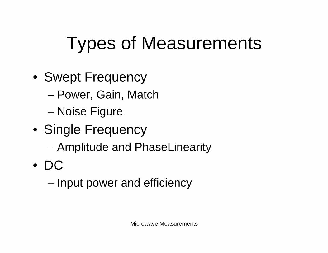
Types of MeasurementsTypes of Measurements
• Swept FrequencySwept Frequency– Power, Gain, Match
Noise Figure– Noise Figure • Single Frequency
– Amplitude and PhaseLinearity• DC
– Input power and efficiency
Microwave Measurements
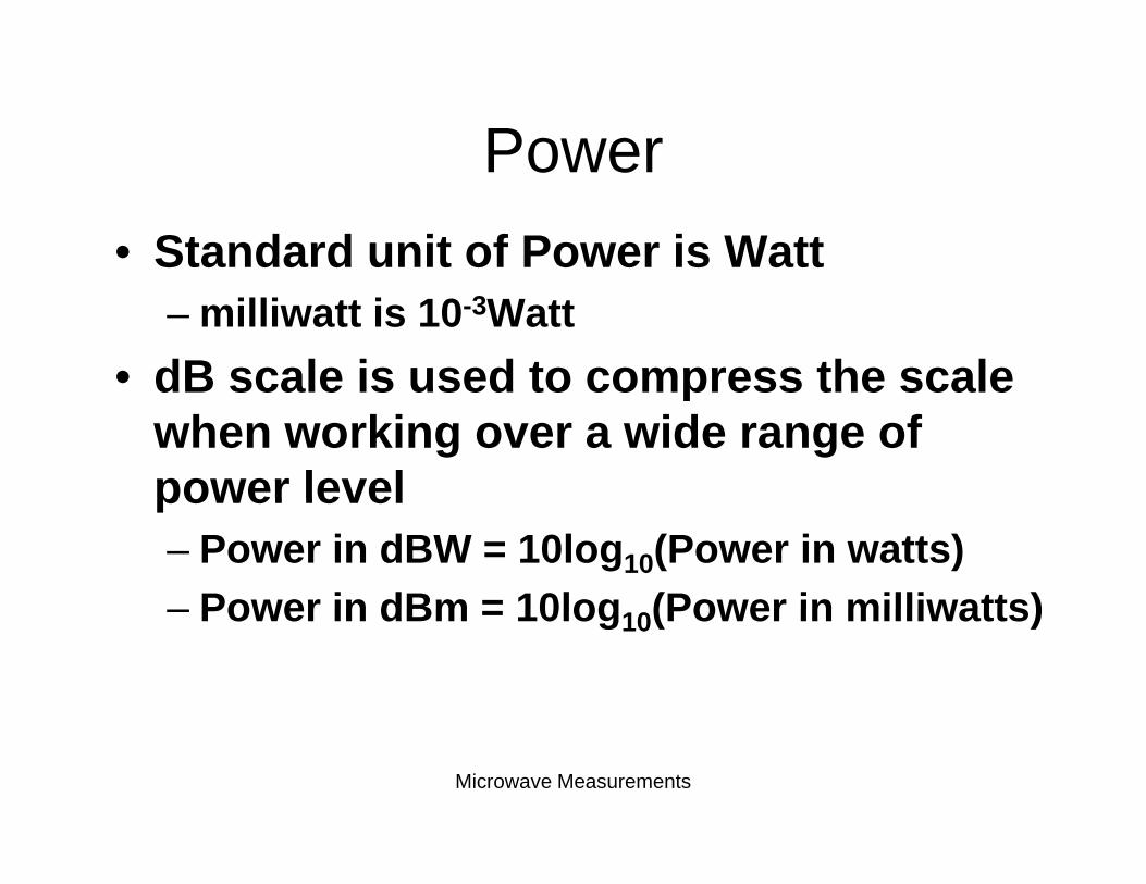
PowerPower• Standard unit of Power is Watt
– milliwatt is 10-3Watt • dB scale is used to compress the scaledB scale is used to compress the scale
when working over a wide range of power levelpower level– Power in dBW = 10log10(Power in watts)– Power in dBm = 10log (Power in milliwatts)– Power in dBm = 10log10(Power in milliwatts)
Microwave Measurements
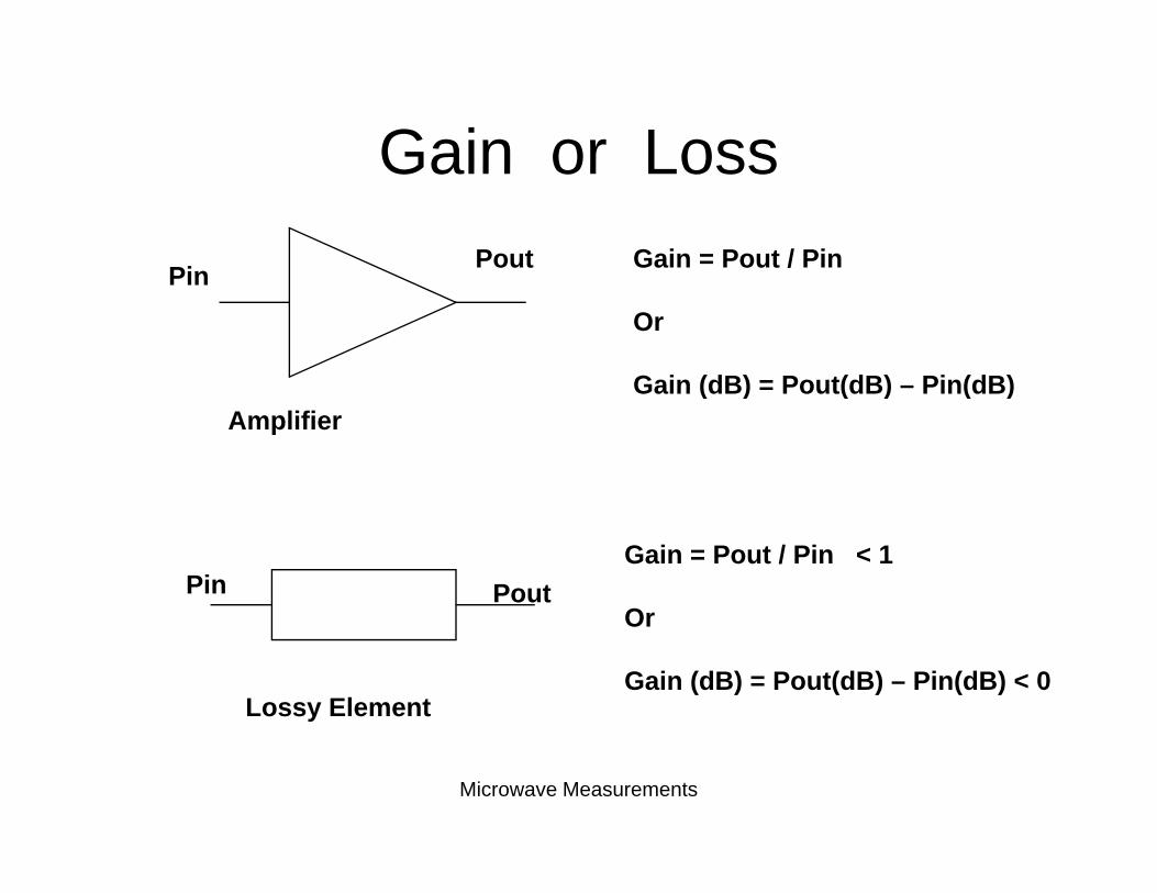
Gain or LossGain or Loss
Pin Pout Gain = Pout / PinPin
Or
Gain (dB) = Pout(dB) – Pin(dB)Gain (dB) Pout(dB) Pin(dB)Amplifier
Pin PoutGain = Pout / Pin < 1
Or
Lossy Element
Or
Gain (dB) = Pout(dB) – Pin(dB) < 0
Microwave Measurements
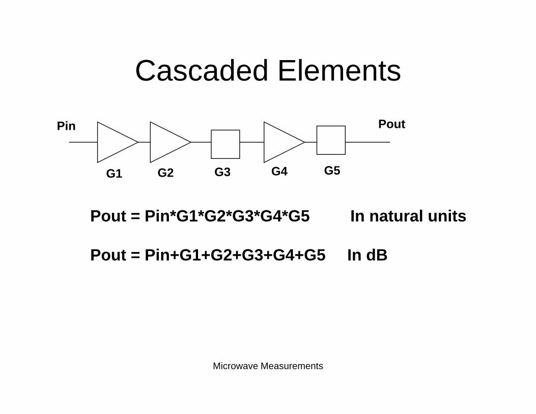
Cascaded ElementsCascaded ElementsPin PoutPin
G1 G2 G3 G4 G5
Pout = Pin*G1*G2*G3*G4*G5 In natural units
Pout = Pin+G1+G2+G3+G4+G5 In dB
Microwave Measurements
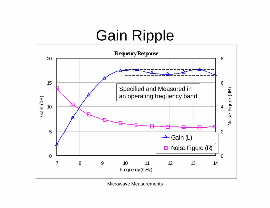
Gain RippleGain RippleFrequency Response
20 8
15 6
B)Specified and Measured in
10
Gai
n (d
B)
4
se F
igur
e (d
BSpec ed a d easu edan operating frequency band
5 2
Noi
s
Gain (L)
7 8 9 10 11 12 13 14Frequency(GHz)
0 0Noise Figure (R)
Microwave Measurements
Frequency (GHz)
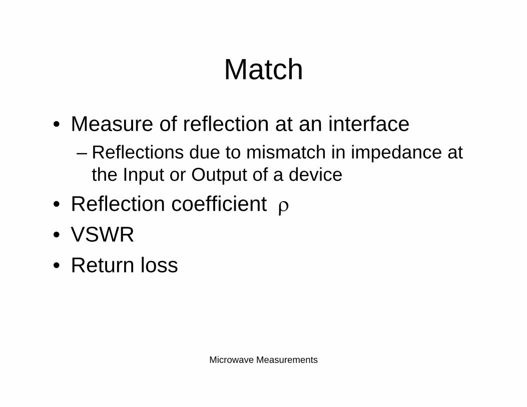
MatchMatch
• Measure of reflection at an interfaceMeasure of reflection at an interface– Reflections due to mismatch in impedance at
the Input or Output of a devicethe Input or Output of a device• Reflection coefficient ρ
VSWR• VSWR• Return loss
Microwave Measurements
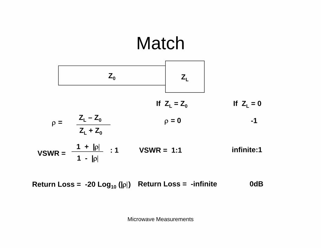
MatchMatchZ0 ZZ0 ZL
If ZL = Z0 If ZL = 0
ρ = ZL – Z0
ZL + Z0
ρ = 0 -1
VSWR =1 + |ρ|1 - |ρ|
VSWR = 1:1: 1 infinite:1
Return Loss = -20 Log10 (|ρ|) Return Loss = -infinite 0dB
Microwave Measurements
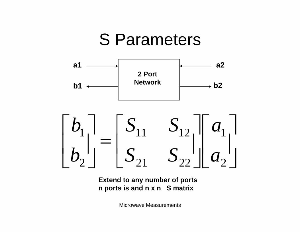
S ParametersS Parameters
2 P ta1 a2
2 PortNetworkb1 b2
⎤⎡⎤⎡⎤⎡ 112111 aSSb⎥⎦
⎤⎢⎣
⎡⎥⎦
⎤⎢⎣
⎡=⎥
⎦
⎤⎢⎣
⎡
2
1
2221
1211
2
1
aa
SSSS
bb
⎦⎣⎦⎣⎦⎣ 222212 aSSbExtend to any number of portsn ports is and n x n S matrix
Microwave Measurements
n ports is and n x n S matrix
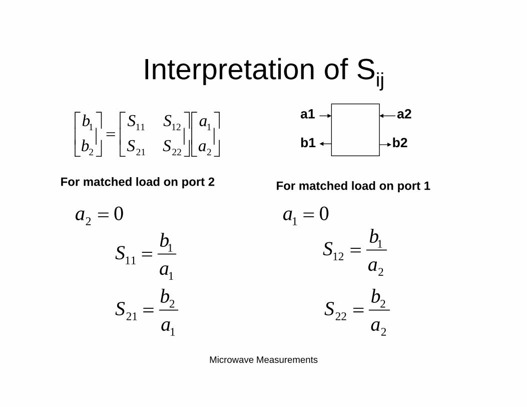
Interpretation of SijInterpretation of Sij
⎤⎡⎤⎡⎤⎡ 112111 aSSb a1 a2
⎥⎦
⎤⎢⎣
⎡⎥⎦
⎤⎢⎣
⎡=⎥
⎦
⎤⎢⎣
⎡
2
1
2221
1211
2
1
aSSb b1 b2
F t h d l d t 2For matched load on port 2 For matched load on port 1
b02 =a 01 =a
1
111 a
bS =2
112 a
bS =
1
221 a
bS =2
222 a
bS =
Microwave Measurements
1 2
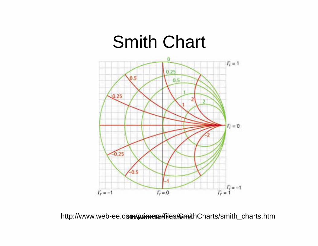
Smith ChartSmith Chart
Microwave Measurementshttp://www.web-ee.com/primers/files/SmithCharts/smith_charts.htm
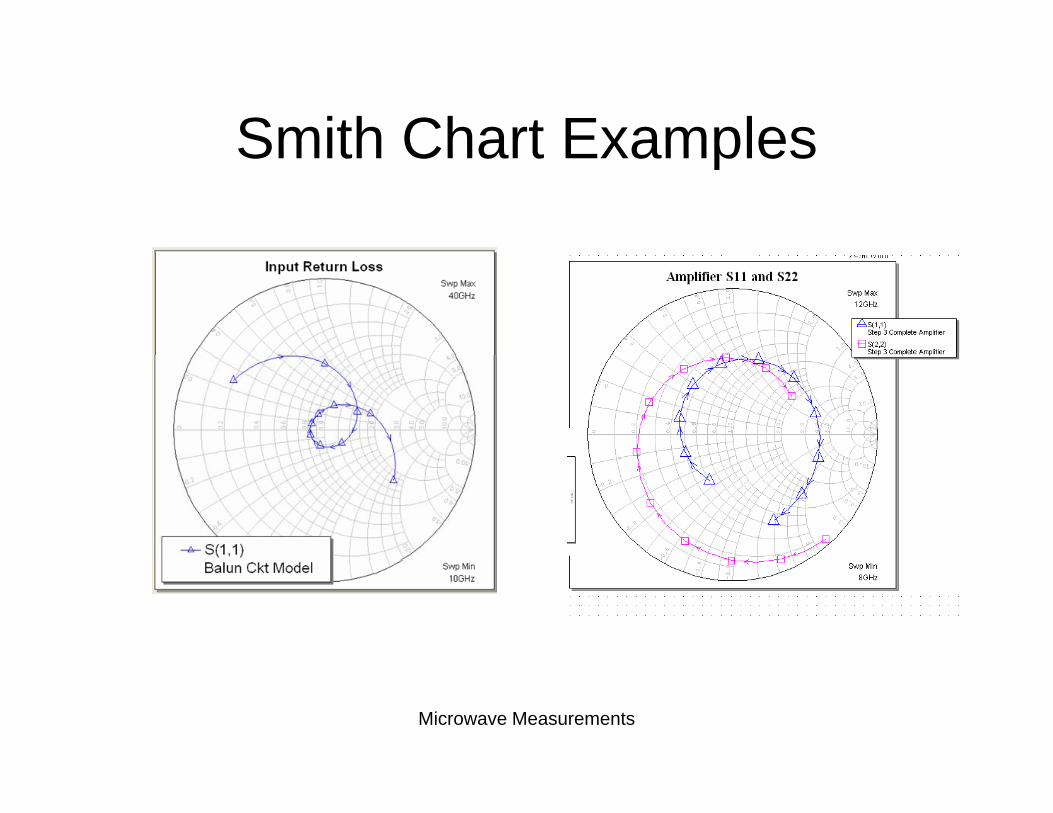
Smith Chart ExamplesSmith Chart Examples
Microwave Measurements
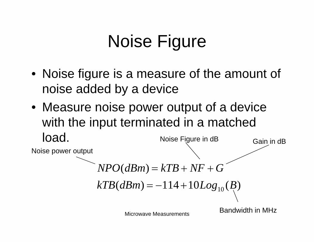
Noise FigureNoise Figure
• Noise figure is a measure of the amount ofNoise figure is a measure of the amount of noise added by a device
• Measure noise power output of a device• Measure noise power output of a device with the input terminated in a matched load N i Fi i dBload.
)( GNFkTBdBmNPO ++
Noise power output
Noise Figure in dB Gain in dB
)(10114)()(
10 BLogdBmkTBGNFkTBdBmNPO
+−=++=
Microwave Measurements Bandwidth in MHz
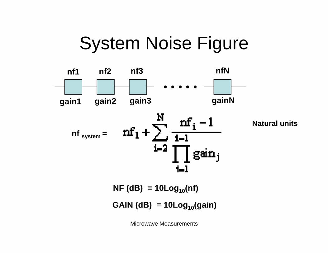
System Noise FigureSystem Noise Figurenf1 nf2 nf3 nfN
gain1 gain2 gain3 gainN
nf system =Natural units
NF (dB) = 10Log10(nf)
GAIN (dB) = 10Log10(gain)
Microwave Measurements
GAIN (dB) 10Log10(gain)
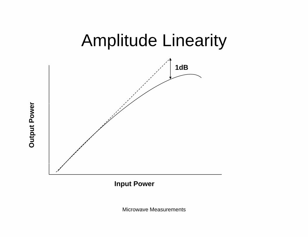
Amplitude LinearityAmplitude Linearity1dB
rpu
t Pow
erO
utp
Input Power
Microwave Measurements
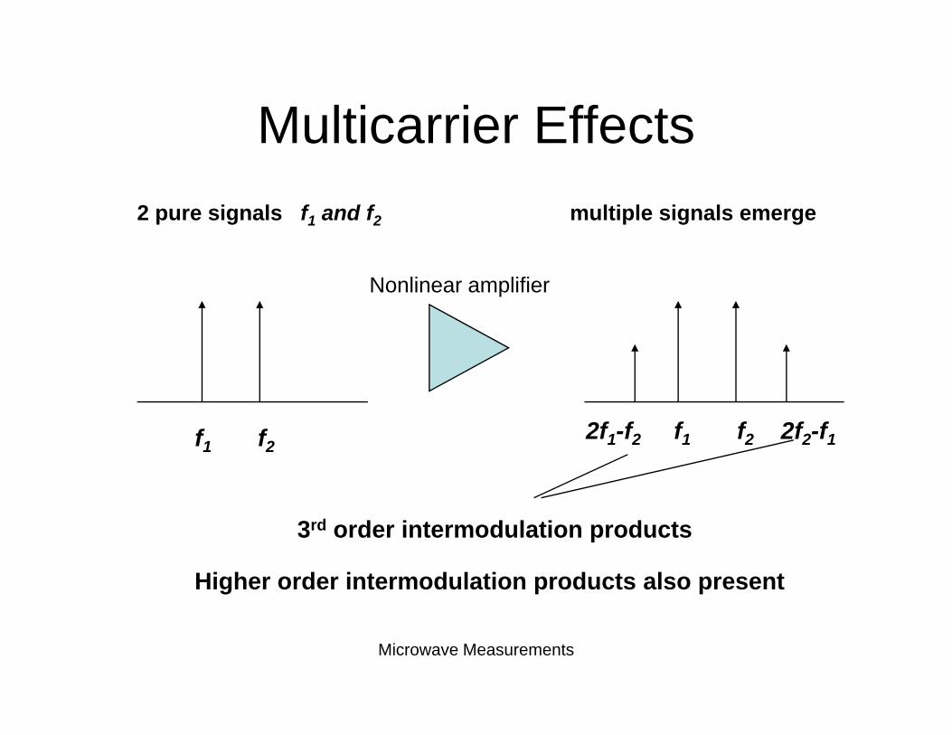
Multicarrier EffectsMulticarrier Effects2 pure signals f1 and f2 multiple signals emerge
Nonlinear amplifier
f1 f22f1-f2 f1 f2 2f2-f1
3rd order intermodulation products
Higher order intermodulation products also present
Microwave Measurements
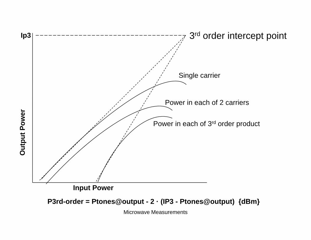
3rd order intercept pointIp3
Single carrierSingle carrier
Power in each of 2 carriers
t Pow
er
o e eac o ca e s
Power in each of 3rd order product
Out
pu
Input Power
Microwave Measurements
P3rd-order = Ptones@output - 2 · (IP3 - Ptones@output) {dBm}
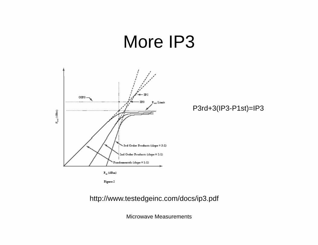
More IP3More IP3
P3rd+3(IP3 P1st)=IP3P3rd+3(IP3-P1st)=IP3
http://www testedgeinc com/docs/ip3 pdf
Microwave Measurements
http://www.testedgeinc.com/docs/ip3.pdf
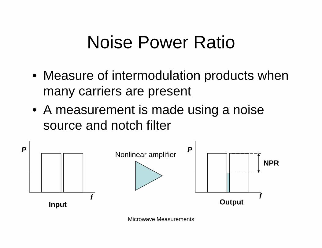
Noise Power RatioNoise Power Ratio
• Measure of intermodulation products whenMeasure of intermodulation products when many carriers are present
• A measurement is made using a noise• A measurement is made using a noise source and notch filter
Nonlinear amplifierNPR
P P
I t Outputf f
Microwave Measurements
Input Output
DCDC
• Input power PDC in WattsInput power PDC in Watts• Output power PRF in Watts
O t t ffi i P P• Output efficiency = PRF / PDC
– Usually expressed in percent• Power added efficiency
– Removes the contribution of input RFp– PAE = (PRF - PRFin ) / PDC
Microwave Measurements
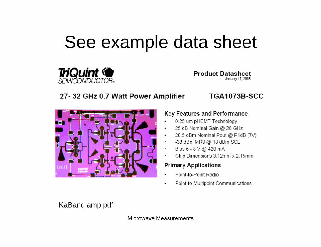
See example data sheetSee example data sheet
Microwave Measurements
KaBand amp.pdf