Embed Size (px)
Citation preview
Operating Manual
Oxitest Plus7
Pulse Oximeter Tester


Oxitest Plus7Pulse Oximeter Tester
Operating Manual
© 2003-2014 Datrend Systems Inc.Unit 130 - 4020 Viking Way
Richmond, BC • CANADA • V6V 2L4Tel: 800.667.6557 (North America Only) or
604.291.7747 • Fax 604.294.2355e-mail [email protected]

To order this manual, use Part Number 6100-105Revision
Revision HistoryDescription Date
E New Corporate Address 2014-Dec-09
CopyrightDatrend Systems Inc. (“DSI”) agrees to a limited copyright release that allows you to reproduce manualsand other printed materials for use in service training programs and other technical publications. If youwould like other reproductions or distributions, submit a written request to Datrend Systems Inc.
Unpacking and InspectionFollow standard receiving practices upon receipt of the instrument. Check the shipping carton fordamage. If damage is found, stop unpacking the instrument. Notify the freight carrier and ask for anagent to be present while the instrument is unpacked. There are no special unpacking instructions, butbe careful not to damage the instrument when unpacking it. Inspect the instrument for physical damagesuch as bent or broken parts, dents, or scratches.
ClaimsOur routine method of shipment is via common carrier. Upon delivery, if physical damage is found,retain all packing materials in their original condition and contact the carrier immediately to file a claim.
If the instrument is delivered in good physical condition but does not operate within specifications, or ifthere are any other problems not caused by shipping damage, please contact your local salesrepresentative or DSI immediately.
Standard Terms and Conditions
Refunds & CreditsPlease note only serialized products (products labeled with a distinct serial number) and accessories areeligible for partial refund and/or credit. Non-serialized parts and accessory items (cables, carrying cases,auxiliary modules, etc.) are not eligible for return or refund. In order to receive a partial refund/credit, theproduct must not have been damaged, and must be returned complete (meaning all manuals, cables,accessories, etc.) within 90 days of original purchase and in “as new” and resalable condition. TheReturn Procedure must be followed.
Return ProcedureEvery product returned for refund/credit must be accompanied by a Return Material Authorization (RMA)number, obtained from Datrend Customer Service. All items being returned must be sent prepaid(freight, duty, brokerage, and taxes ) to our factory location.
Restocking ChargesProducts returned within 30 days of original purchase are subject to a minimum restocking fee of 15%.Products returned in excess of 30 days after purchase, but prior to 90 days, are subject to a minimumrestocking fee of 20%. Additional charges for damage and/or missing parts and accessories will beapplied to all returns. Products which are not in “as new” and resalable condition, are not eligible forcredit return and will be returned to the customer at their expense.
CertificationThis instrument was thoroughly tested and inspected and found to meet DSI's manufacturingspecifications when it was shipped from the factory. Calibration measurements are traceable to theNational Research Council of Canada (NRC) and/or the National Institute of Standards and Technology(NIST). Devices for which there are no NRC/NIST calibration standards are measured against in-houseperformance standards using accepted test procedures.
Warranty
Warranty and Product SupportDatrend Systems Inc. ("DSI") warrants this instrument to be free from defects in materials andworkmanship under normal use and service for one (1) year from the date of original purchase. Thiswarranty will be automatically extended to a maximum of five (5) years from the date of originalpurchase provided that calibration is performed on an annual basis by a Datrend Authorized ServiceCenter (refer to Section 6.2 of this manual).
This warranty is subject to the following limitations:! Oxitest Battery Pack: 90 day limited warranty! Standard Accessories: 90 day limited warranty! Re-calibration of the instrument, which has a recommended annual calibration frequency, is not
covered under the warranty.
During the warranty period DSI will, at our option, either repair or replace a product that proves to bedefective at no charge; provided you return the product (shipping, duty, brokerage and taxes prepaid) toDSI. Any and all transportation charges incurred are the responsibility of the purchaser and are notincluded within this warranty. This warranty extends only to the original purchaser and does not coverdamage from abuse, neglect, accident or misuse or as the result of service or modification by other thanDSI. IN NO EVENT SHALL DATREND SYSTEMS INC. BE LIABLE FOR CONSEQUENTIALDAMAGES.
No warranty shall apply when damage is caused by any of the following:! Power failure, surges, or spikes,! Damage in transit or when moving the instrument,! Improper power supply such as low voltage, incorrect voltage, defective wiring or inadequate fuses,! Accident, alteration, abuse or misuse of the instrument,! Fire, water damage, theft, war, riot, hostility, acts of God, such as hurricanes, floods, etc.
Only serialized products (those items bearing a distinct serial number tag) and their standard accessoryitems are covered under this warranty. PHYSICAL DAMAGE CAUSED BY MISUSE OR PHYSICALABUSE IS NOT COVERED UNDER THE WARRANTY. Items such as cables and non-serializedmodules are not covered under this warranty.
This warranty gives you specific legal rights and you may have other rights, which vary from province toprovince, state to state, or country to country. This warranty is limited to repairing the instrument toDSI's specifications.
When you return a DSI instrument for service, repair or calibration, we recommend shipment using theoriginal shipping foam and container. If the original packing materials are not available, we recommendthe following guide for repackaging:! Use a double-walled carton of sufficient strength for the weight being shipped.! Use heavy paper or cardboard to protect all instrument surfaces. Use non-abrasive material around
all projecting parts.! Use at least four inches of tightly packed, industrial-approved, shock-absorbent material all around
the instrument.
DSI will not be responsible for lost shipments or instruments received in damaged condition due toimproper packaging or handling. All warranty claim shipments must be made on a prepaid basis(freight, duty, brokerage, and taxes). No returns will be accepted without a Return MaterialsAuthorization ("RMA) number. Please contact Datrend at 1-800-667-6557 to obtain an RMA numberand receive help with shipping/customs documentation.

Warranty DisclaimerShould you elect to have your instrument serviced and/or calibrated by someone other than DatrendSystems, please be advised that the original warranty covering your product becomes void when thetamper-resistant Quality Seal is removed or broken without proper factory authorization. We stronglyrecommend, therefore, that you send your instrument to Datrend Systems for service and calibration,especially during the original warranty period.
In all cases, breaking the tamper-resistant Quality Seal should be avoided at all cost, as this seal is thekey to your original instrument warranty. In the event that the seal must be broken to gain internalaccess to the instrument (e.g., in the case of a customer-installed firmware upgrade), you must firstcontact Datrend Systems at 1-800-667-6557. You will be required to provide us with the serial numberfor your instrument as well as a valid reason for breaking the Quality Seal. You should break this sealonly after you have received factory authorization. Do not break the Quality Seal before you havecontacted us! Following these steps will help ensure that you will retain the original warranty on yourinstrument without interruption.
WARNINGUnauthorized user modifications or application beyond the published specifications may result inelectrical shock hazards or improper operation. Datrend Systems will not be responsible for any injuriessustained due to unauthorized equipment modifications.
DSI DISCLAIMS ALL OTHER WARRANTIES, EXPRESSED OR IMPLIED, INCLUDING ANYWARRANTY OF MERCHANTABILITY OR FITNESS FOR A PARTICULAR PURPOSE ORAPPLICATION.
THIS PRODUCT CONTAINS NO USER-SERVICEABLE COMPONENTS. UNAUTHORIZEDREMOVAL OF THE INSTRUMENT COVER SHALLVOID THIS AND ALL OTHER EXPRESSED ORIMPLIED WARRANTIES.

Nellcor® is a registered trademark of Tyco Healthcare
QBasic™ and Visual Basic™ are trademarks of Microsoft Corp.
MS-DOS® is a registered trademark of Microsoft Corp.
OXITEST PLUS 7 OPERATING MANUAL
Table of Contents
1. Specifications . . . . . . . . . . . . . . . . . . . . . . . . . . . . . . . . . . . . . . . . . . . . . . . . . . . . . . . . . . . . . . . . . . . . 1
2. Overview . . . . . . . . . . . . . . . . . . . . . . . . . . . . . . . . . . . . . . . . . . . . . . . . . . . . . . . . . . . . . . . . . . . . . . . . 52.1 General Description . . . . . . . . . . . . . . . . . . . . . . . . . . . . . . . . . . . . . . . . . . . . . . . . . . . . . . . . . . 52.2 Detailed Description . . . . . . . . . . . . . . . . . . . . . . . . . . . . . . . . . . . . . . . . . . . . . . . . . . . . . . . . . . 6
3. Operation . . . . . . . . . . . . . . . . . . . . . . . . . . . . . . . . . . . . . . . . . . . . . . . . . . . . . . . . . . . . . . . . . . . . . . . 93.1 General Description . . . . . . . . . . . . . . . . . . . . . . . . . . . . . . . . . . . . . . . . . . . . . . . . . . . . . . . . . . 93.2 Powering Up, and Modifying the Oxitest Plus 7 Menu . . . . . . . . . . . . . . . . . . . . . . . . . . . . . . . 113.3 Setting Display Contrast . . . . . . . . . . . . . . . . . . . . . . . . . . . . . . . . . . . . . . . . . . . . . . . . . . . . . . 123.4 Choosing an Oximeter . . . . . . . . . . . . . . . . . . . . . . . . . . . . . . . . . . . . . . . . . . . . . . . . . . . . . . . 133.5 Selecting an SpO2 level . . . . . . . . . . . . . . . . . . . . . . . . . . . . . . . . . . . . . . . . . . . . . . . . . . . . . . 143.6 Selecting a Heart Rate . . . . . . . . . . . . . . . . . . . . . . . . . . . . . . . . . . . . . . . . . . . . . . . . . . . . . . . 153.7 Selecting a Pulse Amplitude . . . . . . . . . . . . . . . . . . . . . . . . . . . . . . . . . . . . . . . . . . . . . . . . . . 153.8 Status Indicator . . . . . . . . . . . . . . . . . . . . . . . . . . . . . . . . . . . . . . . . . . . . . . . . . . . . . . . . . . . . 163.9 Selecting Motion Artifact Simulation . . . . . . . . . . . . . . . . . . . . . . . . . . . . . . . . . . . . . . . . . . . . . 173.10 Selecting Auto Presets . . . . . . . . . . . . . . . . . . . . . . . . . . . . . . . . . . . . . . . . . . . . . . . . . . . . . . . 183.11 Selecting Alarm Tests . . . . . . . . . . . . . . . . . . . . . . . . . . . . . . . . . . . . . . . . . . . . . . . . . . . . . . . 183.12 Saving and Printing Test Results . . . . . . . . . . . . . . . . . . . . . . . . . . . . . . . . . . . . . . . . . . . . . . . 223.13 Using the Nellcor Sensor Port . . . . . . . . . . . . . . . . . . . . . . . . . . . . . . . . . . . . . . . . . . . . . . . . . 243.14 ECG Trigger Output . . . . . . . . . . . . . . . . . . . . . . . . . . . . . . . . . . . . . . . . . . . . . . . . . . . . . . . . . 263.15 Recharging the Battery . . . . . . . . . . . . . . . . . . . . . . . . . . . . . . . . . . . . . . . . . . . . . . . . . . . . . . 27
4. Computer Control and RS-232 . . . . . . . . . . . . . . . . . . . . . . . . . . . . . . . . . . . . . . . . . . . . . . . . . . . . . . 294.1 Electrical Interface . . . . . . . . . . . . . . . . . . . . . . . . . . . . . . . . . . . . . . . . . . . . . . . . . . . . . . . . . . 294.2 Mechanical Interface . . . . . . . . . . . . . . . . . . . . . . . . . . . . . . . . . . . . . . . . . . . . . . . . . . . . . . . . 304.3 Functional Description . . . . . . . . . . . . . . . . . . . . . . . . . . . . . . . . . . . . . . . . . . . . . . . . . . . . . . . 304.4 Command Definitions . . . . . . . . . . . . . . . . . . . . . . . . . . . . . . . . . . . . . . . . . . . . . . . . . . . . . . . . 31
4.4.1 Select Oximeter and Initialize Simulation . . . . . . . . . . . . . . . . . . . . . . . . . . . . . . . . . . 314.4.2 Set SpO2 Command . . . . . . . . . . . . . . . . . . . . . . . . . . . . . . . . . . . . . . . . . . . . . . . . . . 324.4.3 Set Heart Rate Command . . . . . . . . . . . . . . . . . . . . . . . . . . . . . . . . . . . . . . . . . . . . . . 324.4.4 Set Pulse Amplitude Command . . . . . . . . . . . . . . . . . . . . . . . . . . . . . . . . . . . . . . . . . 324.4.5 Activate Artifact Simulation . . . . . . . . . . . . . . . . . . . . . . . . . . . . . . . . . . . . . . . . . . . . . 334.4.6 Activate Auto Preset Protocol . . . . . . . . . . . . . . . . . . . . . . . . . . . . . . . . . . . . . . . . . . . 334.4.7 Download Test Report . . . . . . . . . . . . . . . . . . . . . . . . . . . . . . . . . . . . . . . . . . . . . . . . 334.4.8 Download Manual Record . . . . . . . . . . . . . . . . . . . . . . . . . . . . . . . . . . . . . . . . . . . . . . 344.4.9 Download Auto Preset Test Record . . . . . . . . . . . . . . . . . . . . . . . . . . . . . . . . . . . . . . 344.4.10 Download Alarm Test Record . . . . . . . . . . . . . . . . . . . . . . . . . . . . . . . . . . . . . . . . . . . 344.4.11 Erase All Test Records . . . . . . . . . . . . . . . . . . . . . . . . . . . . . . . . . . . . . . . . . . . . . . . . 344.4.12 Command Summary . . . . . . . . . . . . . . . . . . . . . . . . . . . . . . . . . . . . . . . . . . . . . . . . . . 35
4.5 Programming Example . . . . . . . . . . . . . . . . . . . . . . . . . . . . . . . . . . . . . . . . . . . . . . . . . . . . . . 36
5. Test Usage Guidelines . . . . . . . . . . . . . . . . . . . . . . . . . . . . . . . . . . . . . . . . . . . . . . . . . . . . . . . . . . . . 395.1 General Rules . . . . . . . . . . . . . . . . . . . . . . . . . . . . . . . . . . . . . . . . . . . . . . . . . . . . . . . . . . . . . 39
5.1.1 Interpretation of Results . . . . . . . . . . . . . . . . . . . . . . . . . . . . . . . . . . . . . . . . . . . . . . . 395.1.2 Probe/Sensor Interface . . . . . . . . . . . . . . . . . . . . . . . . . . . . . . . . . . . . . . . . . . . . . . . . 40
5.2 Diagnosing Sensor Faults . . . . . . . . . . . . . . . . . . . . . . . . . . . . . . . . . . . . . . . . . . . . . . . . . . . . 485.3 Cross-Manufacturer Compatibility . . . . . . . . . . . . . . . . . . . . . . . . . . . . . . . . . . . . . . . . . . . . . . 49
Table of Contents # Page i

OXITEST PLUS 7 OPERATING MANUAL
6. Routine Maintenance . . . . . . . . . . . . . . . . . . . . . . . . . . . . . . . . . . . . . . . . . . . . . . . . . . . . . . . . . . . . . 516.1 Probe Cleaning . . . . . . . . . . . . . . . . . . . . . . . . . . . . . . . . . . . . . . . . . . . . . . . . . . . . . . . . . . . . 516.2 Calibration . . . . . . . . . . . . . . . . . . . . . . . . . . . . . . . . . . . . . . . . . . . . . . . . . . . . . . . . . . . . . . . . 52
Table of Contents # Page ii
OXITEST PLUS 7 OPERATING MANUAL
1. Specifications1.1 Saturation (SpO2)
Range of adjustment is according to pulse oximeter manufacturer and/or model.
Masimo, Mindray, Nellcor, and Nellcor OEM's (e.g., Critikon; Protocol; Philips; etc.):
Variable from 35% to 100% in steps of 1%SpO2 presets at 35, 70, 80, 90, 93, and 97%
Selected EnviteC, Hewlett-Packard, Nihon Kohden, and Philips models:
Variable from 55% to 100% in steps of 1%SpO2 presets at 55, 70, 80, 90, 93, and 97%
All other manufacturers and models:
Variable from 70% to 100% in steps of 1%SpO2 presets at 70, 80, 90, 93, and 97%
1.2 SpO2 Accuracy
All supported oximeters except Datex and Invivo oximeters:
55 to 100% SpO2: ±1% at specified SpO2 presets35% SpO2: ±2%
Nellcor accuracy specified with either DS100A sensor, or with SpO2 calibrationselected via Nellcor Port.
Specifications/Chapter 1 # Page 1
OXITEST PLUS 7 OPERATING MANUAL
Datex and Invivo oximeters:
±1% at 97, 93% SpO2
±2% at 90, 80, 70% SpO2
1.3 Heart Rate
Variable from 20 to 250 beats per minute (BPM) in 1 BPM steps
Presets: 30, 60, 90, 120, 180, 240 BPMAccuracy: ± 1 BPM
1.4 Pulse Amplitude
Variable from zero (no blood flow) to 100% (normal adult pulse) in 1% steps.
Presets: 100%, 30%, 10%, and 5%Accuracy: ± 1%
1.5 Signal Artifact
Four preset simulations:
MovementTapping (Spike artifact)Shivering (Tremor artifact)Shake Table (2.5Hz Sinewave)
1.6 Auto Presets
Nine preset patient simulations. Factory default Auto Presets are:
Normal Adult HypoxiaTachycardia BradycardiaLow Perfusion No PerfusionMovement Artifact NeonateTremor (Shivering Artifact)
Auto Preset parameters may be user-programmed via the RS-232 port.
Specifications/Chapter 1 # Page 2

OXITEST PLUS 7 OPERATING MANUAL
1.7 Alarm Tests
Five automated test sequences for determining oximeter alarm response time to Low SpO2;Low Heart Rate; High Heart Rate; Low Perfusion; and Motion Artifact conditions. Alsodetermines time required for oximeter alarm to self-clear after test conditions are returned tonormal.
Alarm Test parameters may be user-programmed via the RS-232 port.
1.8 Memory
Auto Preset and Alarm Test results saved in battery-backed, non-volatile Memory, alongwith up to 20 PASS/FAIL records from manually-conducted tests. Test results in Memorymay be printed as a Test Report via optional external Printer, or may be downloaded via RS-232 port to personal computer or automated tester.
1.9 Pulse Oximeter Make / Model
Major makes and models supported. Refer to the Oxitest Plus 7 product CD, orwww.datrend.com, for a detailed listing.
1.10 User Interface
Display:
LCD - 20 character x 2 line
Keypad - 15 keys:
PULSE OX, SPO2 (%), HEART RATE (preset), HR•, HR–, PULSE AMP (preset), PUL• , PUL–, PASS, FAIL, AUTO (preset), ALARM TEST, START/STOP (alarmtest), ERASE (memory), PRINT
1.11 Nellcor Port
Allows temporary connection of Nellcor pulse oximeter sensors for selection of sensor-specific SpO2 calibration curve. Intended for high-accuracy testing of all Nellcor disposableand re-usable sensors.
Specifications/Chapter 1 # Page 3
OXITEST PLUS 7 OPERATING MANUAL
1.12 Serial / Printer Interface
Mechanical: 5 Pin Mini-DINElectrical: Bi-directional RS-232. 9600 baud, 8 bits, no parity, 1 stop.
1.13 Power Supply
Battery: 7.2V rechargeable.Capacity: 1.4 AhBattery life: 40 hours continuous
1.14 Environment
15OC to 40OC, 10% to 90% RHIndoor Use OnlyCategory IIPollution Degree 2Altitude 2000m (max)
Note: Mains supply voltage fluctuations not to exceed +/- 10% of the nominal supplyvoltage.
1.15 Standard Accessories
AC Adapter (all models): 100-240 VAC 50/60 Hz to 12 VDC adaptor; P/N: 3000-025
And one of the Blade Sets for P/N 3000-025:
North America: P/N: 3000-401Europe: P/N: 3000-402
United Kingdom: P/N: 3000-403Australia: P/N: 3000-404
1.16 Optional Accessories
For a complete list of available accessories, visit www.datrend.com or contact DatrendCustomer Service (see section 6.2 for contact details)
Specifications/Chapter 1 # Page 4
OXITEST PLUS 7 OPERATING MANUAL
2. Overview2.1 General Description
The Oxitest Plus 7 Pulse Oximeter Tester is a portable, battery operated device designed to testthe operation of pulse oximeters and their optical sensors. In use, a pulse oximeter sensor is placedon the Oxitest Plus 7 probe. Oxitest Plus 7 transmits an optical signal to the pulse oximetersensor which simulates a predetermined oxygen saturation (SpO2) level, at a given heart rate andsignal strength (pulse amplitude). Proper operation of the pulse oximeter is confirmed if theparameters measured by the oximeter match those generated by Oxitest Plus 7.
Oxitest Plus 7 provides four simulations of patient motion artifacts: gross body movement,tapping the oximeter sensor, shivering or trembling, and shake table laboratory test. Oxitest Plus 7also provides 9 preset simulations to test oximeters under realistic clinical conditions, and fiveautomated oximeter alarm tests. High accuracy testing of Nellcor sensors is available through theuse of Nellcor’s sensor specific calibration curves. Auto Preset, Alarm and manual test results maybe output to a printer, or downloaded to a PC or automated tester for easy documentation.
Most problems with pulse oximeters can be traced to complete or partial failure of the oximetersensor (the photo sensor, one of the two light transmitting elements [LEDs], the cable, or theconnector). Oxitest Plus 7 will assist in diagnosing sensor failures by providing an indication ofthe status of the oximeter’s LEDs.
For comprehensive testing of sensors when no pulse oximeter is available, Datrend provides acompanion test instrument: Sensitest.
Overview/Chapter 2 # Page 5
OXITEST PLUS 7 OPERATING MANUAL
2.2 Detailed Description
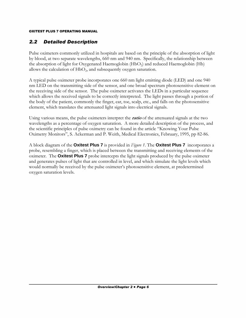
Pulse oximeters commonly utilized in hospitals are based on the principle of the absorption of lightby blood, at two separate wavelengths, 660 nm and 940 nm. Specifically, the relationship betweenthe absorption of light for Oxygenated Haemoglobin (HbO2) and reduced Haemoglobin (Hb)allows the calculation of HbO2, and subsequently oxygen saturation.
A typical pulse oximeter probe incorporates one 660 nm light emitting diode (LED) and one 940nm LED on the transmitting side of the sensor, and one broad spectrum photosensitive element onthe receiving side of the sensor. The pulse oximeter activates the LEDs in a particular sequencewhich allows the received signals to be correctly interpreted. The light passes through a portion ofthe body of the patient, commonly the finger, ear, toe, scalp, etc., and falls on the photosensitiveelement, which translates the attenuated light signals into electrical signals.
Using various means, the pulse oximeters interpret the ratio of the attenuated signals at the twowavelengths as a percentage of oxygen saturation. A more detailed description of the process, andthe scientific principles of pulse oximetry can be found in the article “Knowing Your PulseOximetry Monitors”, S. Ackerman and P. Weith, Medical Electronics, February, 1995, pp 82-86.
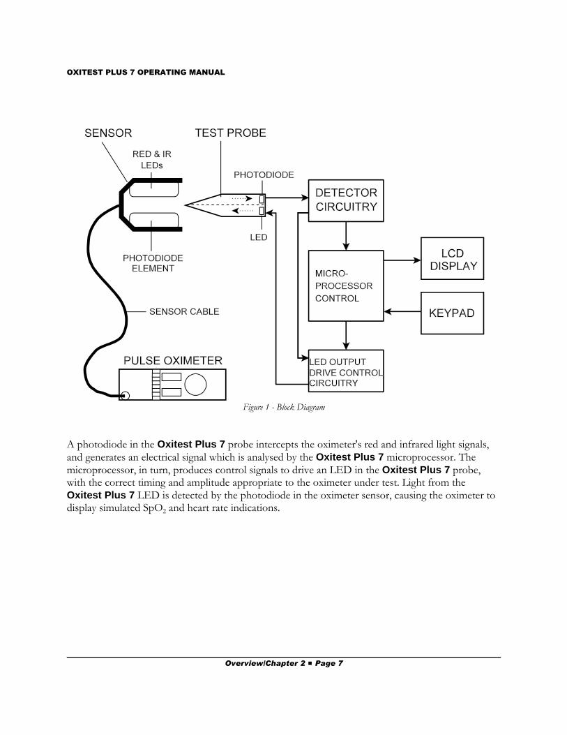
A block diagram of the Oxitest Plus 7 is provided in Figure 1. The Oxitest Plus 7 incorporates aprobe, resembling a finger, which is placed between the transmitting and receiving elements of theoximeter. The Oxitest Plus 7 probe intercepts the light signals produced by the pulse oximeterand generates pulses of light that are controlled in level, and which simulate the light levels whichwould normally be received by the pulse oximeter’s photosensitive element, at predeterminedoxygen saturation levels.
Overview/Chapter 2 # Page 6
OXITEST PLUS 7 OPERATING MANUAL
Figure 1 - Block Diagram
A photodiode in the Oxitest Plus 7 probe intercepts the oximeter's red and infrared light signals,and generates an electrical signal which is analysed by the Oxitest Plus 7 microprocessor. Themicroprocessor, in turn, produces control signals to drive an LED in the Oxitest Plus 7 probe,with the correct timing and amplitude appropriate to the oximeter under test. Light from theOxitest Plus 7 LED is detected by the photodiode in the oximeter sensor, causing the oximeter todisplay simulated SpO2 and heart rate indications.
Overview/Chapter 2 # Page 7

OXITEST PLUS 7 OPERATING MANUAL
Overview/Chapter 2 # Page 8
OXITEST PLUS 7 OPERATING MANUAL
3. Operation3.1 General Description
The Oxitest Plus 7 provides a quick and efficient method of testing the overall operation of a pulseoximeter, its cable and sensor. A test is performed by applying the oximeter sensor to the OxitestPlus 7 probe, after first setting up the test parameters on Oxitest Plus 7. The features of OxitestPlus 7 are depicted in Figure 2 and Figure 3, and are referred to throughout the rest of section 3.
The following procedure should be followed for correct operation:
1. Turn the Oxitest Plus 7 ON by rotating the test probe 90 degrees from its protectivestorage compartment.
2. Following power-up, select an oximeter make (Pulse Ox) from the menu. Set the SpO2,Heart Rate and Pulse Amp to the desired settings using the appropriately labelled pushbutton keys on the front panel. See sections 3.2 through 3.7 for further details. Defaultvalues for SpO2, Heart Rate and Pulse Amp on selection of a new oximeter are 97%, 60BPM and 100% respectively.
3. Turn on the oximeter and examine the sensor to determine which side has the LEDs (thisside will radiate red light). Apply the sensor to the test probe, orienting the sensor with theLEDs on the underside of the probe.
4. Wait for the Oxitest Plus 7 to display "RED+IR OK!" on its LCD.
5. Change Oxitest Plus 7 SpO2 and Heart Rate and note the oximeter's response. Verify theoximeter alarms when SpO2 and/or heart rate exceed corresponding alarm thresholds.Optionally, decrease the Pulse Amp and note how the oximeter's SpO2 and heart rate maybe affected by low tissue perfusion.
6. Remove the oximeter sensor from the test probe.
7. Select a new oximeter (if required) and go back to step (3), or turn Oxitest Plus 7 OFF byrotating the test probe back into the storage compartment.
Operation/Chapter 3 # Page 9

OXITEST PLUS 7 OPERATING MANUAL
Figure 2 - Oxitest Plus 7 Side Panel
Figure 3 - Oxitest Plus 7 Front Panel
Operation/Chapter 3 # Page 10
OXITEST PLUS 7 OPERATING MANUAL
3.2 Powering Up, and Modifying the Oxitest Plus 7 Menu
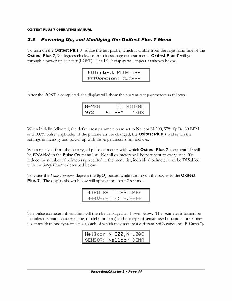
To turn on the Oxitest Plus 7 rotate the test probe, which is visible from the right hand side of theOxitest Plus 7, 90 degrees clockwise from its storage compartment. Oxitest Plus 7 will gothrough a power-on self-test (POST). The LCD display will appear as shown below.
**Oxitest PLUS 7** ***Version: X.X***
After the POST is completed, the display will show the current test parameters as follows.
N-200 NO SIGNAL 97% 60 BPM 100%
When initially delivered, the default test parameters are set to Nellcor N-200, 97% SpO2, 60 BPMand 100% pulse amplitude. If the parameters are changed, the Oxitest Plus 7 will retain thesettings in memory and power up with those parameters on next use.
When received from the factory, all pulse oximeters with which Oxitest Plus 7 is compatible willbe ENAbled in the Pulse Ox menu list. Not all oximeters will be pertinent to every user. Toreduce the number of oximeters presented in the menu list, individual oximeters can be DISabledwith the Setup Function described below.
To enter the Setup Function, depress the SpO2 button while turning on the power to the OxitestPlus 7. The display shown below will appear for about 2 seconds.
**PULSE OX SETUP** ***Version: X.X***
The pulse oximeter information will then be displayed as shown below. The oximeter informationincludes the manufacturer name, model number(s) and the type of sensor used (manufacturers mayuse more than one type of sensor, each of which may require a different SpO2 curve, or “R-Curve”).
Nellcor N-200,N-100C SENSOR: Nellcor >ENA
Operation/Chapter 3 # Page 11
OXITEST PLUS 7 OPERATING MANUAL
The menu of oximeters provides up to 128 entries. The Pulse Amp • or – keys will single-stepthrough the menu sequentially, moving up or down respectively. To move more rapidly through thedifferent menu selections, the Heart Rate • or – keys will move in steps of two entries at a time.
The previous display indicates if the oximeter is currently ENAbled or DISabled. Press the PulseOx key to toggle the ENAbled or DISabled status of the displayed oximeter.
When only the relevant oximeters are ENAbled, press the SpO2 key, and Oxitest Plus 7 will revertto normal operation. The only oximeters that will now be available for selection in the menu ofPulse Ox’s will be those that have been ENAbled. This process may be repeated at any time toENAble or DISable other oximeters.
In the event of a loss of battery power, Oxitest Plus 7 will revert to the factory default settings (alloximeters ENABLED; Pulse Ox = Nellcor N-200; SpO2 = 97%; Heart Rate = 60 BPM; Pulse Amp= 100%).
If it is desirable to reset Oxitest Plus 7 to the factory default settings for any reason, hold down theHeart Rate preset key while powering up the unit. The display will appear as shown below. Inresponse to the LCD prompt, the factory defaults are loaded by pressing the YES (Pass) key or theNo (Fail) key.
Load default setup? YES (•) or NO (–)
3.3 Setting Display Contrast
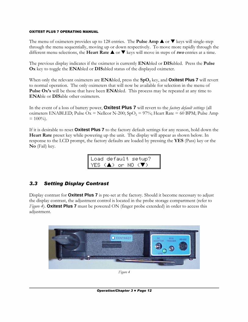
Display contrast for Oxitest Plus 7 is pre-set at the factory. Should it become necessary to adjustthe display contrast, the adjustment control is located in the probe storage compartment (refer to Figure 4). Oxitest Plus 7 must be powered ON (finger probe extended) in order to access thisadjustment.
Figure 4
Operation/Chapter 3 # Page 12
OXITEST PLUS 7 OPERATING MANUAL
3.4 Choosing an Oximeter
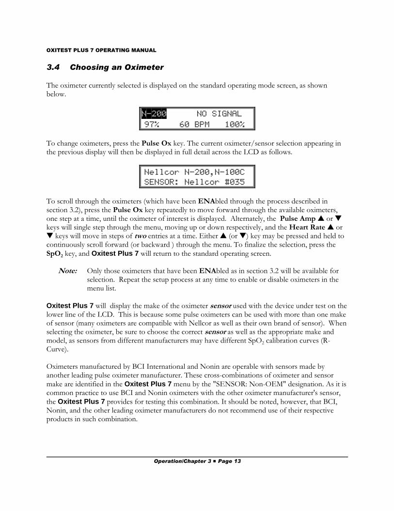
The oximeter currently selected is displayed on the standard operating mode screen, as shownbelow.
N-200 NO SIGNAL 97% 60 BPM 100%
To change oximeters, press the Pulse Ox key. The current oximeter/sensor selection appearing inthe previous display will then be displayed in full detail across the LCD as follows.
Nellcor N-200,N-100C SENSOR: Nellcor #035
To scroll through the oximeters (which have been ENAbled through the process described insection 3.2), press the Pulse Ox key repeatedly to move forward through the available oximeters,one step at a time, until the oximeter of interest is displayed. Alternately, the Pulse Amp • or –keys will single step through the menu, moving up or down respectively, and the Heart Rate • or– keys will move in steps of two entries at a time. Either • (or –) key may be pressed and held tocontinuously scroll forward (or backward ) through the menu. To finalize the selection, press theSpO2 key, and Oxitest Plus 7 will return to the standard operating screen.
Note: Only those oximeters that have been ENAbled as in section 3.2 will be available forselection. Repeat the setup process at any time to enable or disable oximeters in themenu list.
Oxitest Plus 7 will display the make of the oximeter sensor used with the device under test on thelower line of the LCD. This is because some pulse oximeters can be used with more than one makeof sensor (many oximeters are compatible with Nellcor as well as their own brand of sensor). Whenselecting the oximeter, be sure to choose the correct sensor as well as the appropriate make andmodel, as sensors from different manufacturers may have different SpO2 calibration curves (R-Curve).
Oximeters manufactured by BCI International and Nonin are operable with sensors made byanother leading pulse oximeter manufacturer. These cross-combinations of oximeter and sensormake are identified in the Oxitest Plus 7 menu by the "SENSOR: Non-OEM" designation. As it iscommon practice to use BCI and Nonin oximeters with the other oximeter manufacturer's sensor,the Oxitest Plus 7 provides for testing this combination. It should be noted, however, that BCI,Nonin, and the other leading oximeter manufacturers do not recommend use of their respectiveproducts in such combination.
Operation/Chapter 3 # Page 13
OXITEST PLUS 7 OPERATING MANUAL
3.5 Selecting an SpO2 level
Oxitest Plus 7 simulates five (5) preset levels of oxygen saturation - 97, 93, 90, 80 and 70%. Additional preset levels of 55% and 35% may also be provided, according to pulse oximetermanufacturer, model number, and sensor (see Section 1.1).
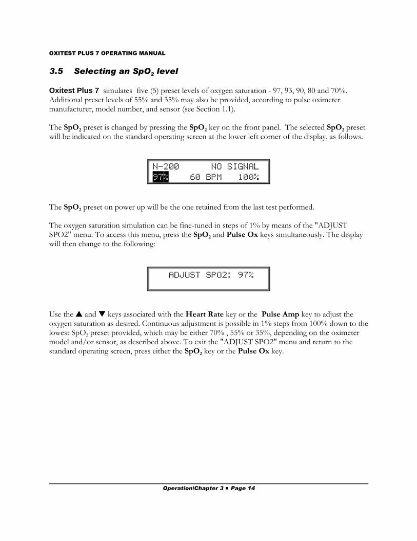
The SpO2 preset is changed by pressing the SpO2 key on the front panel. The selected SpO2 presetwill be indicated on the standard operating screen at the lower left corner of the display, as follows.
N-200 NO SIGNAL 97% 60 BPM 100%
The SpO2 preset on power up will be the one retained from the last test performed.
The oxygen saturation simulation can be fine-tuned in steps of 1% by means of the "ADJUSTSPO2" menu. To access this menu, press the SpO2 and Pulse Ox keys simultaneously. The displaywill then change to the following:
ADJUST SPO2: 97%
Use the • and – keys associated with the Heart Rate key or the Pulse Amp key to adjust theoxygen saturation as desired. Continuous adjustment is possible in 1% steps from 100% down to thelowest SpO2 preset provided, which may be either 70% , 55% or 35%, depending on the oximetermodel and/or sensor, as described above. To exit the "ADJUST SPO2" menu and return to thestandard operating screen, press either the SpO2 key or the Pulse Ox key.
Operation/Chapter 3 # Page 14
OXITEST PLUS 7 OPERATING MANUAL
3.6 Selecting a Heart Rate
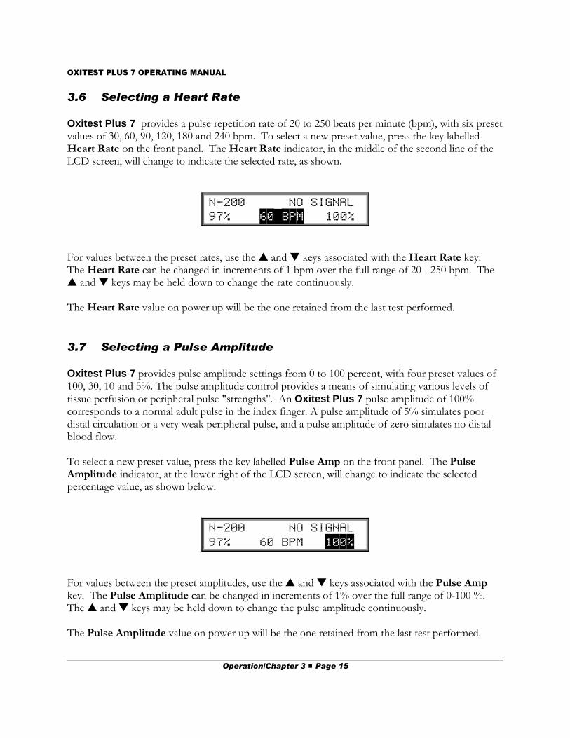
Oxitest Plus 7 provides a pulse repetition rate of 20 to 250 beats per minute (bpm), with six presetvalues of 30, 60, 90, 120, 180 and 240 bpm. To select a new preset value, press the key labelledHeart Rate on the front panel. The Heart Rate indicator, in the middle of the second line of theLCD screen, will change to indicate the selected rate, as shown.
N-200 NO SIGNAL 97% 60$BPM 100%
For values between the preset rates, use the • and – keys associated with the Heart Rate key. The Heart Rate can be changed in increments of 1 bpm over the full range of 20 - 250 bpm. The• and – keys may be held down to change the rate continuously.
The Heart Rate value on power up will be the one retained from the last test performed.
3.7 Selecting a Pulse Amplitude
Oxitest Plus 7 provides pulse amplitude settings from 0 to 100 percent, with four preset values of100, 30, 10 and 5%. The pulse amplitude control provides a means of simulating various levels oftissue perfusion or peripheral pulse "strengths". An Oxitest Plus 7 pulse amplitude of 100%corresponds to a normal adult pulse in the index finger. A pulse amplitude of 5% simulates poordistal circulation or a very weak peripheral pulse, and a pulse amplitude of zero simulates no distalblood flow.
To select a new preset value, press the key labelled Pulse Amp on the front panel. The PulseAmplitude indicator, at the lower right of the LCD screen, will change to indicate the selectedpercentage value, as shown below.
N-200 NO SIGNAL 97% 60 BPM 100%
For values between the preset amplitudes, use the • and – keys associated with the Pulse Ampkey. The Pulse Amplitude can be changed in increments of 1% over the full range of 0-100 %. The • and – keys may be held down to change the pulse amplitude continuously.
The Pulse Amplitude value on power up will be the one retained from the last test performed.
Operation/Chapter 3 # Page 15
OXITEST PLUS 7 OPERATING MANUAL
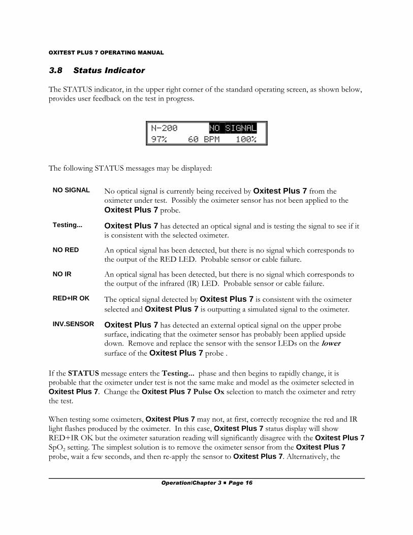
3.8 Status Indicator
The STATUS indicator, in the upper right corner of the standard operating screen, as shown below,provides user feedback on the test in progress.
N-200 NO$SIGNAL 97% 60 BPM 100%
The following STATUS messages may be displayed:
NO SIGNAL No optical signal is currently being received by Oxitest Plus 7 from theoximeter under test. Possibly the oximeter sensor has not been applied to the
Oxitest Plus 7 probe.
Testing... Oxitest Plus 7 has detected an optical signal and is testing the signal to see if itis consistent with the selected oximeter.
NO RED An optical signal has been detected, but there is no signal which corresponds tothe output of the RED LED. Probable sensor or cable failure.
NO IR An optical signal has been detected, but there is no signal which corresponds tothe output of the infrared (IR) LED. Probable sensor or cable failure.
RED+IR OK The optical signal detected by Oxitest Plus 7 is consistent with the oximeter
selected and Oxitest Plus 7 is outputting a simulated signal to the oximeter.
INV.SENSOR Oxitest Plus 7 has detected an external optical signal on the upper probesurface, indicating that the oximeter sensor has probably been applied upsidedown. Remove and replace the sensor with the sensor LEDs on the lowersurface of the Oxitest Plus 7 probe .
If the STATUS message enters the Testing... phase and then begins to rapidly change, it isprobable that the oximeter under test is not the same make and model as the oximeter selected inOxitest Plus 7. Change the Oxitest Plus 7 Pulse Ox selection to match the oximeter and retrythe test.
When testing some oximeters, Oxitest Plus 7 may not, at first, correctly recognize the red and IRlight flashes produced by the oximeter. In this case, Oxitest Plus 7 status display will showRED+IR OK but the oximeter saturation reading will significantly disagree with the Oxitest Plus 7SpO2 setting. The simplest solution is to remove the oximeter sensor from the Oxitest Plus 7probe, wait a few seconds, and then re-apply the sensor to Oxitest Plus 7. Alternatively, the
Operation/Chapter 3 # Page 16
OXITEST PLUS 7 OPERATING MANUAL
oximeter can be powered up after applying the sensor to Oxitest Plus 7. Positioning the sensorproperly may be more difficult for short, stubby sensors. Section 5.1.2 offers some advice on howto position some specific types of sensors.
3.9 Selecting Motion Artifact Simulation
Oxitest Plus 7 provides four waveforms for simulating various motion artifact conditions. The MVwave adds low frequency noise to the normal patient signal, simulating slow, whole-bodymovements. The SP wave adds sharp noise spikes to the patient signal, simulating the oximetersensor being struck or tapped at random times. The TR wave simulates patient tremor or shivering.The Sn wave is a high-amplitude 2.5 Hertz sinewave interference, simulating a "shake table"laboratory test of a pulse oximeter, as described by Barker et al in "The effects of motion on theperformance of pulse oximeters in volunteers", Anesthesiology, 1997; 86:101-8.
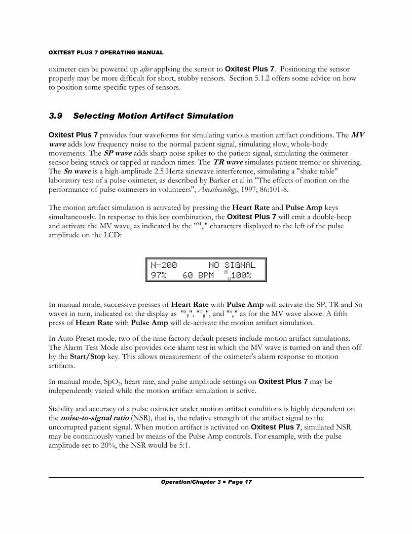
The motion artifact simulation is activated by pressing the Heart Rate and Pulse Amp keyssimultaneously. In response to this key combination, the Oxitest Plus 7 will emit a double-beepand activate the MV wave, as indicated by the "M
V" characters displayed to the left of the pulseamplitude on the LCD:
N-200 NO SIGNAL 97% 60 BPM
M
V100%
In manual mode, successive presses of Heart Rate with Pulse Amp will activate the SP, TR and Snwaves in turn, indicated on the display as "S
P", "TR", and "S
n" as for the MV wave above. A fifthpress of Heart Rate with Pulse Amp will de-activate the motion artifact simulation.
In Auto Preset mode, two of the nine factory default presets include motion artifact simulations.The Alarm Test Mode also provides one alarm test in which the MV wave is turned on and then offby the Start/Stop key. This allows measurement of the oximeter's alarm response to motionartifacts.
In manual mode, SpO2, heart rate, and pulse amplitude settings on Oxitest Plus 7 may beindependently varied while the motion artifact simulation is active.
Stability and accuracy of a pulse oximeter under motion artifact conditions is highly dependent onthe noise-to-signal ratio (NSR), that is, the relative strength of the artifact signal to theuncorrupted patient signal. When motion artifact is activated on Oxitest Plus 7, simulated NSRmay be continuously varied by means of the Pulse Amp controls. For example, with the pulseamplitude set to 20%, the NSR would be 5:1.
Operation/Chapter 3 # Page 17
OXITEST PLUS 7 OPERATING MANUAL
3.10 Selecting Auto Presets
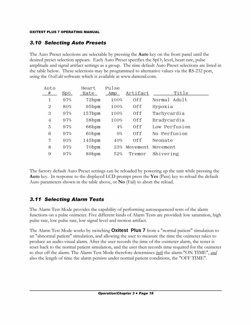
The Auto Preset selections are selectable by pressing the Auto key on the front panel until thedesired preset selection appears. Each Auto Preset specifies the SpO2 level, heart rate, pulseamplitude and signal artifact settings as a group. The nine default Auto Preset selections are listed inthe table below. These selections may be programmed to alternative values via the RS-232 port,using the OxiEdit software which is available at www.datrend.com.
Auto # Sp02
Heart Rate
Pulse Amp Artifact Title
1 97% 72bpm 100% Off Normal Adult
2 80% 95bpm 100% Off Hypoxia
3 97% 157bpm 100% Off Tachycardia
4 97% 38bpm 100% Off Bradycardia
5 97% 66bpm 4% Off Low Perfusion
6 97% 60bpm 0% Off No Perfusion
7 93% 145bpm 40% Off Neonate
8 97% 70bpm 33% Movement Movement
9 97% 89bpm 52% Tremor Shivering
The factory default Auto Preset settings can be reloaded by powering up the unit while pressing theAuto key. In response to the displayed LCD prompt press the Yes (Pass) key to reload the defaultAuto parameters shown in the table above, or No (Fail) to abort the reload.
3.11 Selecting Alarm Tests
The Alarm Test Mode provides the capability of performing autosequenced tests of the alarmfunctions on a pulse oximeter. Five different kinds of Alarm Tests are provided: low saturation, highpulse rate, low pulse rate, low signal level and motion artifact.
The Alarm Test Mode works by switching Oxitest Plus 7 from a "normal patient" simulation toan "abnormal patient" simulation, and allowing the user to measure the time the oximeter takes toproduce an audio-visual alarm. After the user records the time of the oximeter alarm, the tester isreset back to the normal patient simulation, and the user then records time required for the oximeterto shut off the alarm. The Alarm Test Mode therefore determines both the alarm "ON TIME", andalso the length of time the alarm persists under normal patient conditions, the "OFF TIME".
Operation/Chapter 3 # Page 18

OXITEST PLUS 7 OPERATING MANUAL
Pressing the Alarm Test key produces the following LCD display:
LOW SAT ALM T: 00.0 97% 72 BPM 100%
As shown above, the LCD displays the name of the alarm test at the upper left, a timer counter atthe upper right, and the test settings corresponding to the "normal patient" condition on the lowerline.
By pressing the Alarm Test key, the user can select one of the four remaining alarm tests. Inaddition to the test above, the remaining tests appear as follows:
HI RATE ALM T: 00.0 97% 72 BPM 100%
LO RATE ALM T: 00.0 97% 72 BPM 100%
LOW SIG ALM T: 00.0 97% 72 BPM 100%
ARTFACT ALM T: 00.0 97% 72 BPM 100%
As long as the user refrains from pressing the Start/Stop key, Oxitest Plus 7 continuously outputsthe simulation corresponding to the parameters shown on the lower line of the LCD. Pressing theStart/Stop key immediately initiates the selected alarm test by switching the test parameters to theabnormal patient setting, and starts the timer counting in the top right corner of the LCD.
Operation/Chapter 3 # Page 19
OXITEST PLUS 7 OPERATING MANUAL
The effect of the Start/Stop key on the tester depends on the Alarm Test selected by the user, asfollows:
Prior to pushing Start/Stop:
Alarm Test SpO2 Hrt. Rate P. Amp Artifact
All Tests 97% 72 BPM 100% Off
Effect of pushing Start/Stop:
Alarm Test SpO2 Hrt. Rate P. Amp Artifact
#1 - LOW SAT 70% 72 BPM 100% Off#2 - HI RATE 97% 180 BPM 100% Off#3 - LO RATE 97% 40 BPM 100% Off#4 - LOW SIG 97% 72 BPM 3% Off#5 - ARTIFACT 97% 72 BPM 20% MV
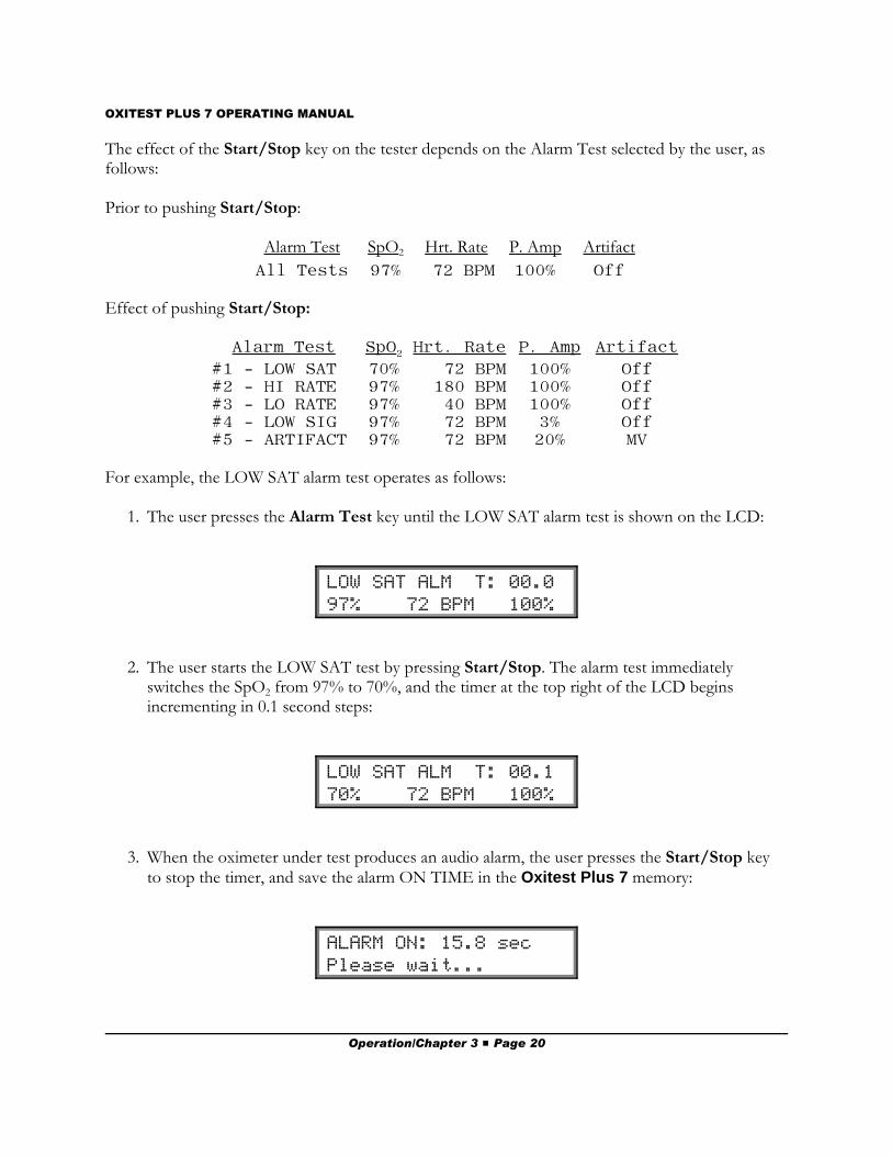
For example, the LOW SAT alarm test operates as follows:
1. The user presses the Alarm Test key until the LOW SAT alarm test is shown on the LCD:
LOW SAT ALM T: 00.0 97% 72 BPM 100%
2. The user starts the LOW SAT test by pressing Start/Stop. The alarm test immediatelyswitches the SpO2 from 97% to 70%, and the timer at the top right of the LCD beginsincrementing in 0.1 second steps:
LOW SAT ALM T: 00.1 70% 72 BPM 100%
3. When the oximeter under test produces an audio alarm, the user presses the Start/Stop keyto stop the timer, and save the alarm ON TIME in the Oxitest Plus 7 memory:
ALARM ON: 15.8 sec Please wait...
Operation/Chapter 3 # Page 20
OXITEST PLUS 7 OPERATING MANUAL
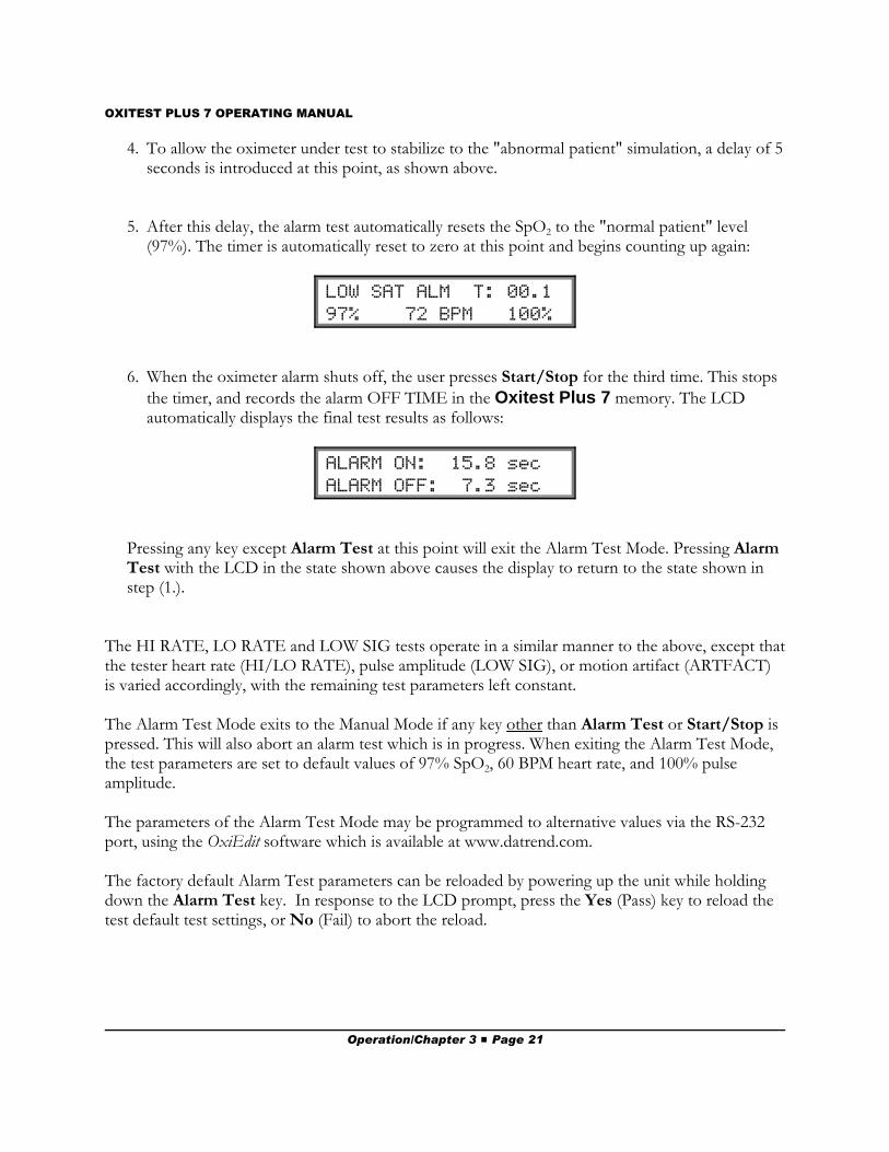
4. To allow the oximeter under test to stabilize to the "abnormal patient" simulation, a delay of 5seconds is introduced at this point, as shown above.
5. After this delay, the alarm test automatically resets the SpO2 to the "normal patient" level(97%). The timer is automatically reset to zero at this point and begins counting up again:
LOW SAT ALM T: 00.1 97% 72 BPM 100%
6. When the oximeter alarm shuts off, the user presses Start/Stop for the third time. This stops
the timer, and records the alarm OFF TIME in the Oxitest Plus 7 memory. The LCDautomatically displays the final test results as follows:
ALARM ON: 15.8 sec ALARM OFF: 7.3 sec
Pressing any key except Alarm Test at this point will exit the Alarm Test Mode. Pressing AlarmTest with the LCD in the state shown above causes the display to return to the state shown instep (1.).
The HI RATE, LO RATE and LOW SIG tests operate in a similar manner to the above, except thatthe tester heart rate (HI/LO RATE), pulse amplitude (LOW SIG), or motion artifact (ARTFACT)is varied accordingly, with the remaining test parameters left constant.
The Alarm Test Mode exits to the Manual Mode if any key other than Alarm Test or Start/Stop ispressed. This will also abort an alarm test which is in progress. When exiting the Alarm Test Mode,the test parameters are set to default values of 97% SpO2, 60 BPM heart rate, and 100% pulseamplitude.
The parameters of the Alarm Test Mode may be programmed to alternative values via the RS-232port, using the OxiEdit software which is available at www.datrend.com.
The factory default Alarm Test parameters can be reloaded by powering up the unit while holdingdown the Alarm Test key. In response to the LCD prompt, press the Yes (Pass) key to reload thetest default test settings, or No (Fail) to abort the reload.
Operation/Chapter 3 # Page 21
OXITEST PLUS 7 OPERATING MANUAL
3.12 Saving and Printing Test Results
Up to 20 PASS/FAIL results from manually-conducted tests may be saved in the memory ofOxitest Plus 7 for later printout or downloading to a personal computer (PC). In addition to the 20manual test results, Oxitest Plus 7 can also save the results of Auto Preset tests and Alarm Tests.
Manual test and Auto Preset test results are saved to Oxitest Plus 7 memory by pressing either thePass or Fail key on the front panel keypad. The information saved includes the test SpO2, heartrate, pulse amplitude and motion artifact settings, plus the PASS or FAIL status of the test and theoximeter signal status displayed at the upper right corner of the Oxitest Plus 7 LCD. The oximetersignal status is saved in abbreviated format as follows: OK = “RED+IR OK”; NoRD = “No Red”;NoIR = “ No IR”; and ?? = “NO SIGNAL” or “Testing”.
For each Alarm Test performed, the oximeter ALARM-ON and ALARM-OFF times areautomatically saved in the Oxitest Plus 7 memory if the Alarm Test is run through to completion.There is no need to press Pass or Fail to save the results of an Alarm Test.
All test results saved in the Oxitest Plus 7 memory are retained by battery back-up when the poweris switched off. This allows test results to be acquired over a period of time and then printed out ordownloaded later.
Pressing the Print key causes the test results saved in the memory to be transmitted from theOxitest Plus 7 RS-232 Port as a formatted “Test Report”. The Oxitest Plus 7 RS-232 Port maybe connected to a Citizen iDP-3110 serial printer or to a personal computer. Refer to section 4.2 forthe interconnection cable details.
The format of the Test Report is similar to the following example printout:
Operation/Chapter 3 # Page 22

OXITEST PLUS 7 OPERATING MANUAL
Oxitest PLUS 7 Pulse Oximeter Tester
PULSE OX TEST REPORT
Time/Date: _________________________
Control No.: _________________________ Serial No.: _________________________Location: _________________________Department: _________________________Technician: _________________________
Oxitest settings:PULSE OX: Nellcor N-200, N-100CSENSOR: Nellcor W. SELECTED R-CURVE
--------Oxitest-------- --Status--Rec. SpO2 Rate Amp. Artf LEDs 1 97% 75BPM 100% Off OK PASS 2 93% 75BPM 100% Off OK PASS 3 90% 75BPM 100% Off OK PASS 4 97% 150BPM 30% Off OK PASS 5 97% 240BPM 15% MOVM NoRD FAIL
--------Oxitest-------- --Status--Auto SpO2 Rate Amp. Artf LEDs 1 97% 72BPM 100% Off OK PASS 4 97% 38BPM 100% Off OK PASS 6 97% 60BPM 0% Off NoIR FAIL 9 97% 89BPM 52% TREM OK PASS
ALARM TEST ON-TIME OFF-TIMELOW SAT 9.8 sec 7.1 secHI RATE 10.6 sec 8.5 secLO RATE 17.4 sec 15.1 secLOW SIG 23.1 sec 7.4 sec
In the prior example, the results of five manual tests, four Auto Preset tests and four Alarm Testswere saved. As shown, the Oxitest Plus 7 signal status appears under the “LEDs” column and thePASS or FAIL status of the test result appears at the far right. Manual test #5 shows that theoximeter’s red LED may have been defective, which was recorded as a “FAIL”. Similarly, AutoPreset test #6 was also recorded as a “FAIL” due to a potentially defective infrared LED in theoximeter sensor.
If the printer is not attached, or not on-line when the Print key is pressed, then the error messageshown below will be displayed. The off-line condition is tested immediately after pressing the Printkey and periodically while the printing is in progress.
****** ERROR ****** Printer is OFF-LINE!
The Erase key permits the erasure of the last test record saved (in case PASS or FAIL was pressedat the wrong time or under the wrong conditions) or the erasure of all test records. When the Erasekey is pressed, the display as shown below, results.
Operation/Chapter 3 # Page 23
OXITEST PLUS 7 OPERATING MANUAL
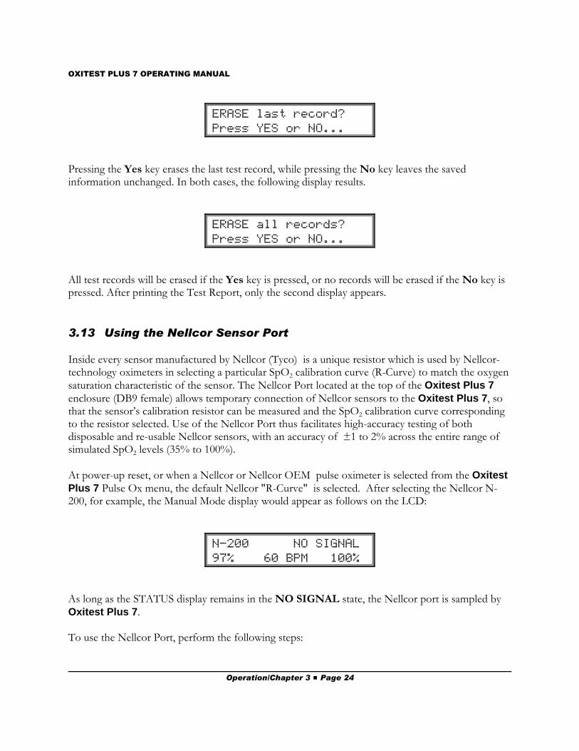
ERASE last record? Press YES or NO...
Pressing the Yes key erases the last test record, while pressing the No key leaves the savedinformation unchanged. In both cases, the following display results.
ERASE all records? Press YES or NO...
All test records will be erased if the Yes key is pressed, or no records will be erased if the No key ispressed. After printing the Test Report, only the second display appears.
3.13 Using the Nellcor Sensor Port
Inside every sensor manufactured by Nellcor (Tyco) is a unique resistor which is used by Nellcor-technology oximeters in selecting a particular SpO2 calibration curve (R-Curve) to match the oxygensaturation characteristic of the sensor. The Nellcor Port located at the top of the Oxitest Plus 7enclosure (DB9 female) allows temporary connection of Nellcor sensors to the Oxitest Plus 7, sothat the sensor’s calibration resistor can be measured and the SpO2 calibration curve correspondingto the resistor selected. Use of the Nellcor Port thus facilitates high-accuracy testing of bothdisposable and re-usable Nellcor sensors, with an accuracy of ±1 to 2% across the entire range ofsimulated SpO2 levels (35% to 100%).
At power-up reset, or when a Nellcor or Nellcor OEM pulse oximeter is selected from the OxitestPlus 7 Pulse Ox menu, the default Nellcor "R-Curve" is selected. After selecting the Nellcor N-200, for example, the Manual Mode display would appear as follows on the LCD:
N-200 NO SIGNAL 97% 60 BPM 100%
As long as the STATUS display remains in the NO SIGNAL state, the Nellcor port is sampled byOxitest Plus 7.
To use the Nellcor Port, perform the following steps:
Operation/Chapter 3 # Page 24
OXITEST PLUS 7 OPERATING MANUAL
1. Select a Nellcor compatible pulse oximeter from the menu.
2. Disconnect the sensor from the pulse oximeter and connect it to the Nellcor Port DB9connector at the top of Oxitest Plus 7.
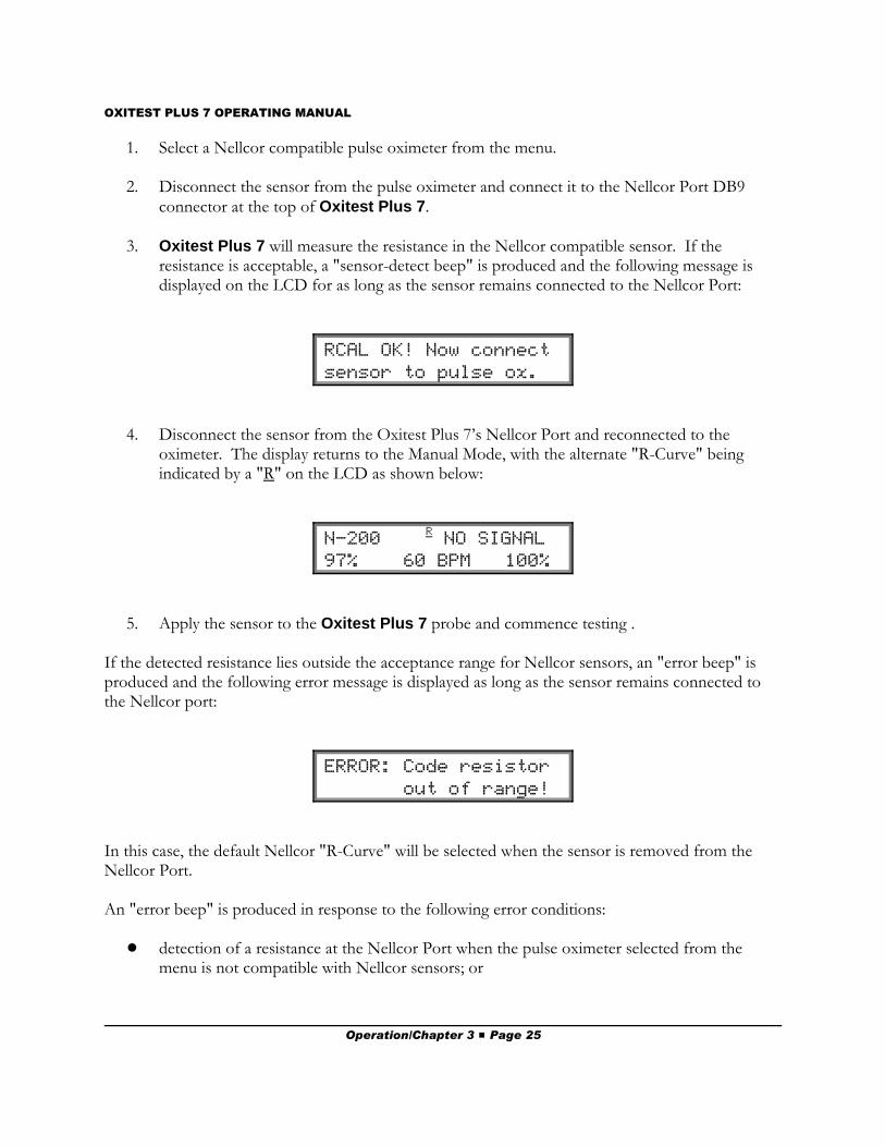
3. Oxitest Plus 7 will measure the resistance in the Nellcor compatible sensor. If theresistance is acceptable, a "sensor-detect beep" is produced and the following message isdisplayed on the LCD for as long as the sensor remains connected to the Nellcor Port:
RCAL OK! Now connect sensor to pulse ox.
4. Disconnect the sensor from the Oxitest Plus 7’s Nellcor Port and reconnected to theoximeter. The display returns to the Manual Mode, with the alternate "R-Curve" beingindicated by a "R" on the LCD as shown below:
N-200 R NO SIGNAL
97% 60 BPM 100%
5. Apply the sensor to the Oxitest Plus 7 probe and commence testing .
If the detected resistance lies outside the acceptance range for Nellcor sensors, an "error beep" isproduced and the following error message is displayed as long as the sensor remains connected tothe Nellcor port:
ERROR: Code resistor out of range!
In this case, the default Nellcor "R-Curve" will be selected when the sensor is removed from theNellcor Port.
An "error beep" is produced in response to the following error conditions:
! detection of a resistance at the Nellcor Port when the pulse oximeter selected from themenu is not compatible with Nellcor sensors; or
Operation/Chapter 3 # Page 25
OXITEST PLUS 7 OPERATING MANUAL
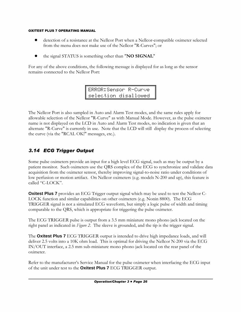
! detection of a resistance at the Nellcor Port when a Nellcor-compatible oximeter selectedfrom the menu does not make use of the Nellcor "R-Curves"; or
! the signal STATUS is something other than "NO SIGNAL"
For any of the above conditions, the following message is displayed for as long as the sensorremains connected to the Nellcor Port:
ERROR:Sensor R-Curve selection disallowed
The Nellcor Port is also sampled in Auto and Alarm Test modes, and the same rules apply forallowable selection of the Nellcor "R-Curve" as with Manual Mode. However, as the pulse oximetername is not displayed on the LCD in Auto and Alarm Test modes, no indication is given that analternate "R-Curve" is currently in use. Note that the LCD will still display the process of selectingthe curve (via the "RCAL OK!" messages, etc.).
3.14 ECG Trigger Output
Some pulse oximeters provide an input for a high level ECG signal, such as may be output by apatient monitor. Such oximeters use the QRS complex of the ECG to synchronize and validate dataacquisition from the oximeter sensor, thereby improving signal-to-noise ratio under conditions oflow perfusion or motion artifact. On Nellcor oximeters (e.g. models N-200 and up), this feature iscalled “C-LOCK”.
Oxitest Plus 7 provides an ECG Trigger output signal which may be used to test the Nellcor C-LOCK function and similar capabilities on other oximeters (e.g. Nonin 8800). The ECGTRIGGER signal is not a simulated ECG waveform, but simply a logic pulse of width and timingcomparable to the QRS, which is appropriate for triggering the pulse oximeter.
The ECG TRIGGER pulse is output from a 3.5 mm miniature mono phono jack located on theright panel as indicated in Figure 2. The sleeve is grounded, and the tip is the trigger signal.
The Oxitest Plus 7 ECG TRIGGER output is intended to drive high impedance loads, and willdeliver 2.5 volts into a 10K ohm load. This is optimal for driving the Nellcor N-200 via the ECGIN/OUT interface, a 2.5 mm sub-miniature mono phono jack located on the rear panel of theoximeter.
Refer to the manufacturer’s Service Manual for the pulse oximeter when interfacing the ECG inputof the unit under test to the Oxitest Plus 7 ECG TRIGGER output.
Operation/Chapter 3 # Page 26
OXITEST PLUS 7 OPERATING MANUAL
3.15 Recharging the Battery
Oxitest Plus 7 is powered by an internal NiCad battery with sufficient capacity to provideapproximately 40 hours of operation. When the Oxitest Plus 7 is OFF, the battery powers a non-volatile memory which retains the test settings, the ENAable/DISable status of the pulse oximetermenu, and any Pass/Fail test results which may have been saved in memory. Power drain from thebattery in this case is negligible.
When the battery approaches full discharge, the STATUS display as shown in Section 3.8 StatusIndicator, will alternate with a LO BATTERY indication. To recharge the battery, plug the suppliedAC adapter into a wall outlet and the Oxitest Plus 7 DC ADAPTOR input (see Figure 2). Useonly the adaptor supplied with the Oxitest Plus 7 to recharge the battery. A full batteryrecharge will require approximately 14 hours.
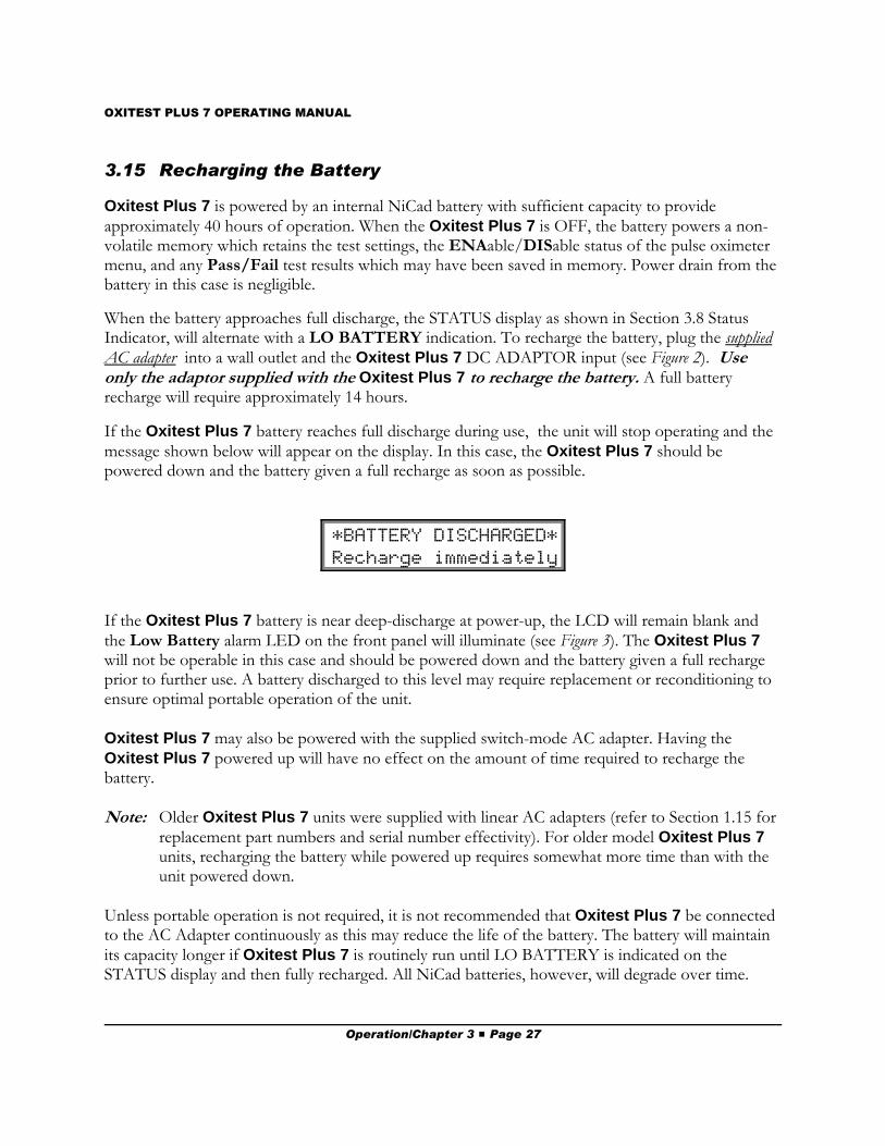
If the Oxitest Plus 7 battery reaches full discharge during use, the unit will stop operating and themessage shown below will appear on the display. In this case, the Oxitest Plus 7 should bepowered down and the battery given a full recharge as soon as possible.
*BATTERY DISCHARGED* Recharge immediately
If the Oxitest Plus 7 battery is near deep-discharge at power-up, the LCD will remain blank andthe Low Battery alarm LED on the front panel will illuminate (see Figure 3). The Oxitest Plus 7will not be operable in this case and should be powered down and the battery given a full rechargeprior to further use. A battery discharged to this level may require replacement or reconditioning toensure optimal portable operation of the unit.
Oxitest Plus 7 may also be powered with the supplied switch-mode AC adapter. Having theOxitest Plus 7 powered up will have no effect on the amount of time required to recharge thebattery.
Note: Older Oxitest Plus 7 units were supplied with linear AC adapters (refer to Section 1.15 forreplacement part numbers and serial number effectivity). For older model Oxitest Plus 7units, recharging the battery while powered up requires somewhat more time than with theunit powered down.
Unless portable operation is not required, it is not recommended that Oxitest Plus 7 be connectedto the AC Adapter continuously as this may reduce the life of the battery. The battery will maintainits capacity longer if Oxitest Plus 7 is routinely run until LO BATTERY is indicated on theSTATUS display and then fully recharged. All NiCad batteries, however, will degrade over time.
Operation/Chapter 3 # Page 27
OXITEST PLUS 7 OPERATING MANUAL
Newer Oxitest Plus 7 units feature battery monitoring and protection circuitry. In the event theOxitest Plus 7 battery becomes deeply discharged, the protection circuit will disconnect the batteryinternally when the battery voltage falls below a set threshold voltage. This typically occurs when aunit with an older battery is left on the shelf for a prolonged period of time.
Notes:
! If the battery is discharged to the point where the protection circuitry activates,reconditioning of the battery may be indicated if an overnight charge does not restore thebattery to full capacity.
! Once the protection circuitry has internally disconnected the battery, Oxitest Plus 7 willnot power up by turning the finger probe. To reset the unit, the switch-mode AC adaptermust be plugged into the AC mains and connected to Oxitest Plus 7. This can be donewith the Oxitest Plus 7 ON or OFF. Once reset, Oxitest Plus 7 can be used with the ACadapter, or without the AC adpater, once the battery has been fully charged.
! When the protection circuitry disconnects the battery, all saved data and settings will be lost.
The Oxitest Plus 7 battery can be removed for replacement or reconditioning through the batterycompartment access door on the underside of the unit.
Notes:
! Once the battery has been physically disconnected from the unit, Oxitest Plus 7 will notpower up by turning the finger probe. To reset the unit, the switch-mode AC adapter mustbe plugged in to the AC mains and connected to Oxitest Plus 7. This can be done with theOxitest Plus 7 ON or OFF.
! When the battery is physically disconnected from the unit, all saved data and settings will belost.
Operation/Chapter 3 # Page 28
OXITEST PLUS 7 OPERATING MANUAL
4. Computer Control and RS-232The operating parameters of Oxitest Plus 7 can be controlled by an external device, through anRS-232 serial communications port. This allows Oxitest Plus 7 to be interfaced to an automatedtester or PC for automated oximeter testing. It also allows the control of the test parameters, datatransfer, and remote editing of Oximeter Menu, Auto Preset and Alarm Test settings.Oxitest Plus 7 may be operated via the front panel keypad while simultaneously responding tocommands via the RS-232 port. The five control commands (Select Oximeter; Set SpO2; Set HeartRate; Set Pulse Amplitude, and Activate Artifact Simulation), and three of the download commands(Download Manual, Auto Preset and Alarm Test Record) are all compatible with most automatedsafety analyzers.
4.1 Electrical Interface
RS-232, Bidirectional, 9600 baud, 8 bits, No parity, 1 stop bit.
Maximum cable length restricted to 10 feet.
Computer Control/Chapter 4 # Page 29
OXITEST PLUS 7 OPERATING MANUAL
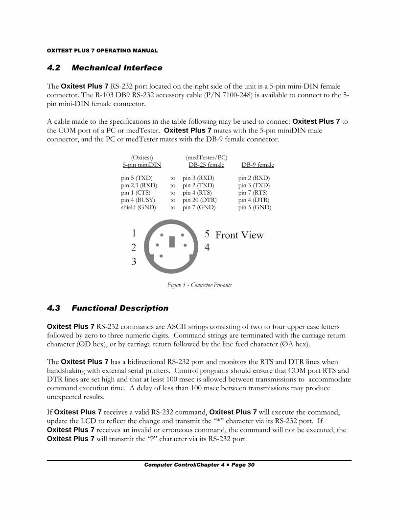
Figure 5 - Connector Pin-outs
4.2 Mechanical Interface
The Oxitest Plus 7 RS-232 port located on the right side of the unit is a 5-pin mini-DIN femaleconnector. The R-103 DB9 RS-232 accessory cable (P/N 7100-248) is available to connect to the 5-pin mini-DIN female connector.
A cable made to the specifications in the table following may be used to connect Oxitest Plus 7 tothe COM port of a PC or medTester. Oxitest Plus 7 mates with the 5-pin miniDIN maleconnector, and the PC or medTester mates with the DB-9 female connector.
(Oxitest)5-pin miniDIN
(medTester/PC)DB-25 female DB-9 female
pin 5 (TXD)pin 2,3 (RXD)pin 1 (CTS)pin 4 (BUSY)shield (GND)
tototototo
pin 3 (RXD)pin 2 (TXD)pin 4 (RTS)pin 20 (DTR)pin 7 (GND)
pin 2 (RXD)pin 3 (TXD)pin 7 (RTS)pin 4 (DTR)pin 5 (GND)
4.3 Functional Description
Oxitest Plus 7 RS-232 commands are ASCII strings consisting of two to four upper case lettersfollowed by zero to three numeric digits. Command strings are terminated with the carriage returncharacter (ØD hex), or by carriage return followed by the line feed character (ØA hex).
The Oxitest Plus 7 has a bidirectional RS-232 port and monitors the RTS and DTR lines whenhandshaking with external serial printers. Control programs should ensure that COM port RTS andDTR lines are set high and that at least 100 msec is allowed between transmissions to accommodatecommand execution time. A delay of less than 100 msec between transmissions may produceunexpected results.
If Oxitest Plus 7 receives a valid RS-232 command, Oxitest Plus 7 will execute the command,update the LCD to reflect the change and transmit the “*” character via its RS-232 port. IfOxitest Plus 7 receives an invalid or erroneous command, the command will not be executed, theOxitest Plus 7 will transmit the “?” character via its RS-232 port.
Computer Control/Chapter 4 # Page 30
OXITEST PLUS 7 OPERATING MANUAL
4.4 Command Definitions
For all RS-232 commands, be sure to follow the prescribed syntax, including leading zeroswhere indicated. Failure to do so may result in unexpected operation of the Oxitest Plus 7.
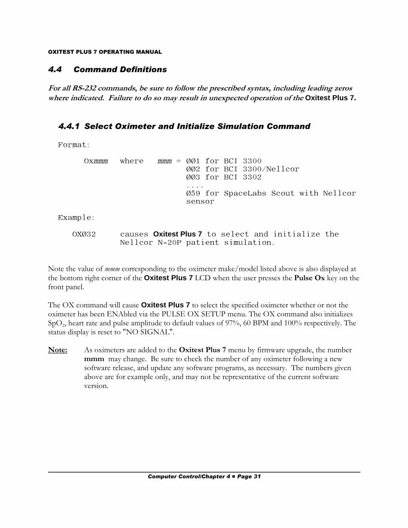
4.4.1 Select Oximeter and Initialize Simulation Command
Format:
Oxmmm where mmm = ØØ1 for BCI 3300ØØ2 for BCI 3300/NellcorØØ3 for BCI 3302....Ø59 for SpaceLabs Scout with Nellcorsensor
Example:
OXØ32 causes Oxitest Plus 7 to select and initialize theNellcor N-20P patient simulation.
Note the value of mmm corresponding to the oximeter make/model listed above is also displayed atthe bottom right corner of the Oxitest Plus 7 LCD when the user presses the Pulse Ox key on thefront panel.
The OX command will cause Oxitest Plus 7 to select the specified oximeter whether or not theoximeter has been ENAbled via the PULSE OX SETUP menu. The OX command also initializesSpO2, heart rate and pulse amplitude to default values of 97%, 60 BPM and 100% respectively. Thestatus display is reset to "NO SIGNAL".
Note: As oximeters are added to the Oxitest Plus 7 menu by firmware upgrade, the number mmm may change. Be sure to check the number of any oximeter following a newsoftware release, and update any software programs, as necessary. The numbers givenabove are for example only, and may not be representative of the current softwareversion.
Computer Control/Chapter 4 # Page 31
OXITEST PLUS 7 OPERATING MANUAL
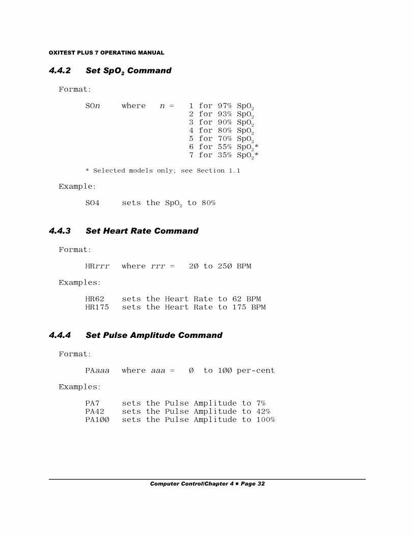
4.4.2 Set SpO2 Command
Format:
SOn where n = 1 for 97% SpO22 for 93% SpO23 for 90% SpO24 for 80% SpO25 for 70% SpO26 for 55% SpO2*7 for 35% SpO2*
* Selected models only; see Section 1.1
Example:
SO4 sets the SpO2 to 80%
4.4.3 Set Heart Rate Command
Format:
HRrrr where rrr = 2Ø to 25Ø BPM
Examples:
HR62 sets the Heart Rate to 62 BPMHR175 sets the Heart Rate to 175 BPM
4.4.4 Set Pulse Amplitude Command
Format:
PAaaa where aaa = Ø to 1ØØ per-cent
Examples:
PA7 sets the Pulse Amplitude to 7%PA42 sets the Pulse Amplitude to 42%PA1ØØ sets the Pulse Amplitude to 100%
Computer Control/Chapter 4 # Page 32
OXITEST PLUS 7 OPERATING MANUAL
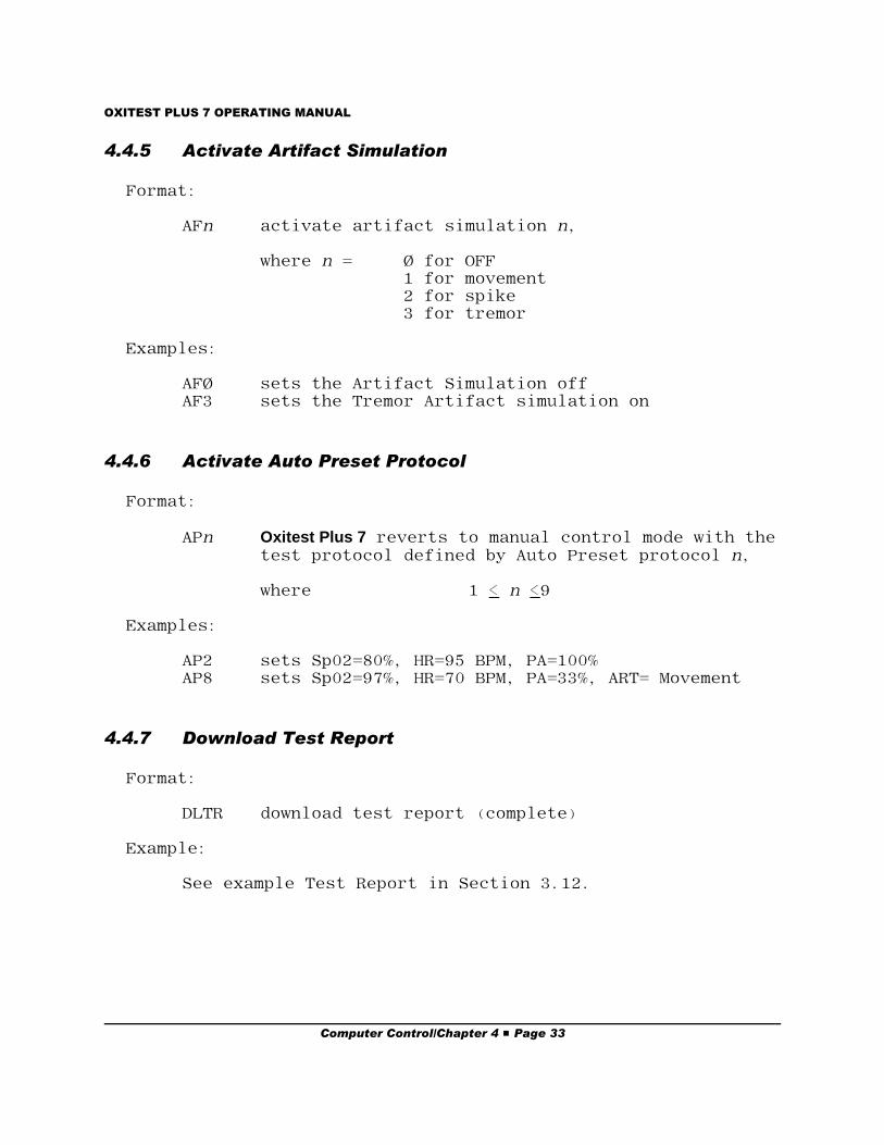
4.4.5 Activate Artifact Simulation
Format:
AFn activate artifact simulation n,
where n = Ø for OFF1 for movement2 for spike3 for tremor
Examples:
AFØ sets the Artifact Simulation offAF3 sets the Tremor Artifact simulation on
4.4.6 Activate Auto Preset Protocol
Format:
APn Oxitest Plus 7 reverts to manual control mode with thetest protocol defined by Auto Preset protocol n,
where 1 < n <9
Examples:
AP2 sets Sp02=80%, HR=95 BPM, PA=100%AP8 sets Sp02=97%, HR=70 BPM, PA=33%, ART= Movement
4.4.7 Download Test Report
Format:
DLTR download test report (complete)
Example:
See example Test Report in Section 3.12.
Computer Control/Chapter 4 # Page 33
OXITEST PLUS 7 OPERATING MANUAL
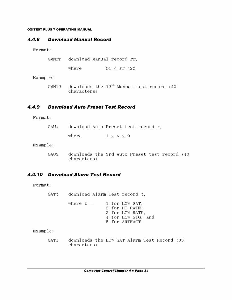
4.4.8 Download Manual Record
Format:
GMNrr download Manual record rr,
where Ø1 < rr <2Ø
Example:
GMN12 downloads the 12th Manual test record (40characters)
4.4.9 Download Auto Preset Test Record
Format:
GAUx download Auto Preset test record x,
where 1 < x < 9
Example:
GAU3 downloads the 3rd Auto Preset test record (40characters)
4.4.10 Download Alarm Test Record
Format:
GATt download Alarm Test record t,
where t = 1 for LOW SAT,2 for HI RATE,3 for LOW RATE,4 for LOW SIG, and5 for ARTFACT.
Example:
GAT1 downloads the LOW SAT Alarm Test Record (35characters)
Computer Control/Chapter 4 # Page 34
OXITEST PLUS 7 OPERATING MANUAL
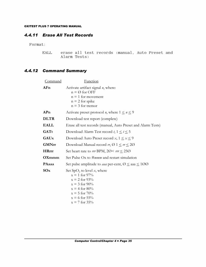
4.4.11 Erase All Test Records
Format:
EALL erase all test records (manual, Auto Preset andAlarm Tests)
4.4.12 Command Summary
Command Function
AFn Activate artifact signal n, where:n = Ø for OFFn = 1 for movementn = 2 for spiken = 3 for tremor
APn Activate preset protocol n, where 1 < n < 9
DLTR Download test report (complete)
EALL Erase all test records (manual, Auto Preset and Alarm Tests)
GATt Download Alarm Test record t, 1 < t < 5
GAUx Download Auto Preset record x, 1 < x < 9
GMNrr Download Manual record rr, Ø 1 < rr < 2Ø
HRrrr Set heart rate to rrr BPM, 2Ø< rrr < 25Ø
OXmmm Set Pulse Ox to #mmm and restart simulation
PAaaa Set pulse amplitude to aaa per-cent, Ø < aaa < 1ØØ
SOx Set SpO2 to level x, where x = 1 for 97%x = 2 for 93%x = 3 for 90%x = 4 for 80%x = 5 for 70%x = 6 for 55%x = 7 for 35%
Computer Control/Chapter 4 # Page 35
OXITEST PLUS 7 OPERATING MANUAL
4.5 Programming Example
Microsoft QBasic is an easy-to-use BASIC interpreter which is supplied as part of Microsoft DOSversions 5 and later. Using QBasic, you can write simple programs on your IBM PC or compatibleto control Oxitest Plus 7 automatically via a COM port.
Below is a simple program written in Microsoft QBasic which causes Oxitest Plus 7 to select aNELLCOR N-200 pulse oximeter for testing and automatically sweep the N-200 through a range ofSpO2 and heart rate settings.
Run Microsoft QBasic from the DOS prompt by simply typing QBasic followed by f (you can also
run QBasic from Windows - double click on the QBasic icon in the APPLICATIONS group.)
QBASIC should boot, showing the "Welcome" screen. Press ^ to clear the screen, or press f to view
the QBasic HELP index.
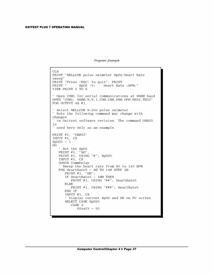
When typing the following example, be sure to include all the punctuation marks which appear inthe program ( " , ; ! % $ and so on).
After you have typed in the program, save it by typing aF, followed by S. To run the example,
connect Oxitest Plus 7 to COM1, set up the NELLCOR N-200, and then type aR followed by S.
To stop the program, press the ^ key. To quit QBASIC, type aF followed by X.
Computer Control/Chapter 4 # Page 36
OXITEST PLUS 7 OPERATING MANUAL
CLSPRINT "NELLCOR pulse oximeter SpO2/Heart Ratesweep"PRINT "Press <ESC> to quit": PRINTPRINT " SpO2 (%) Heart Rate (BPM)"VIEW PRINT 5 TO 6
' Open COM1 for serial communications at 96ØØ baudOPEN "COM1: 96ØØ,N,8,1,CDØ,CSØ,DSØ,OPØ,RB32,TB32"FOR OUTPUT AS #1
' Select NELLCOR N-200 pulse oximeter' Note the following command may change withchanges ' in Oxitest software revision. The command OXØ35is ' used here only as an example. PRINT #1, "OXØ35"INPUT #1, C$SpO2% = 1DO ' Set the SpO2 PRINT #1, "SO"; PRINT #1, USING "#"; SpO2% INPUT #1, C$ GOSUB CommDelay ' Sweep the heart rate from 60 to 140 BPM FOR HeartRate% = 6Ø TO 14Ø STEP 2Ø PRINT #1, "HR"; IF HeartRate% < 1ØØ THEN PRINT #1, USING "##"; HeartRate% ELSE PRINT #1, USING "###"; HeartRate% END IF INPUT #1, C$ ' Display current SpO2 and HR on PC screen SELECT CASE SpO2% CASE 2: O2sat% = 93
Program Example
Computer Control/Chapter 4 # Page 37
OXITEST PLUS 7 OPERATING MANUAL
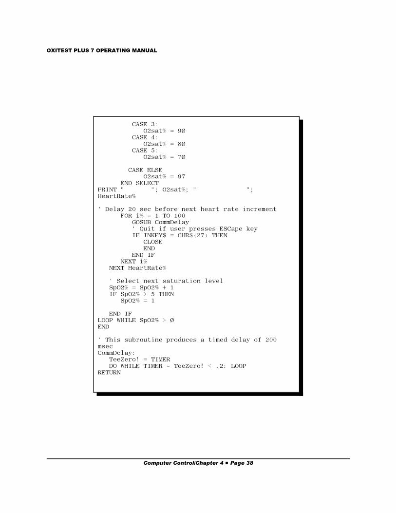
CASE 3: O2sat% = 9Ø CASE 4: O2sat% = 8Ø CASE 5: O2sat% = 7Ø CASE ELSE O2sat% = 97 END SELECTPRINT " "; O2sat%; " ";HeartRate%
' Delay 20 sec before next heart rate increment FOR i% = 1 TO 100 GOSUB CommDelay ' Quit if user presses ESCape key IF INKEY$ = CHR$(27) THEN CLOSE END END IF NEXT i% NEXT HeartRate%
' Select next saturation level SpO2% = SpO2% + 1 IF SpO2% > 5 THEN SpO2% = 1
END IFLOOP WHILE SpO2% > ØEND
' This subroutine produces a timed delay of 200msecCommDelay: TeeZero! = TIMER DO WHILE TIMER - TeeZero! < .2: LOOPRETURN
Computer Control/Chapter 4 # Page 38
OXITEST PLUS 7 OPERATING MANUAL
5. Test Usage Guidelines5.1 General Rules
In an ideal world, testing a pulse oximeter would simply involve placing the oximeter sensor on thetest probe and observing the results. However, due to the many implementations of the basicoximetry technology and many configurations of sensors, there are some practical problems you willinevitably run into in testing oximeters. The problems generally fall into two categories: 1)interpretation of results; and 2) the probe/sensor interface.
5.1.1 Interpretation of Results
Although pulse oximeters provide an indication of heart rate, it is the oxygen saturation estimated bythese devices (SpO2) which is of greater concern when discussing the "accuracy" of a particularmake or model. Manufacturer's accuracy specifications for SpO2 can be confusing - just what does±2% ± 1 standard deviation actually mean? In developing the calibration curve for an oximeter,commonly known as the "R-Curve", the response of the device is statistically compared to theresponse from invasive oxygen content readings from a large population of individuals. Thespecification cited above can be translated as: the oxygen saturation value measured by this oximeterwill be accurate to within 2% for 65% of the population.
This specification has very little to do with what you should expect from testing the oximeter with atester. The R-Curve is well-defined in the oximeter's electronics. An oximeter tester such asOxitest Plus 7 is microprocessor controlled, and as a result outputs a precisely regulated, calibratedoptical signal. Therefore, although there may be some uncertainty introduced by the sensor and thesensor/tester interface, the response from an electro-optical simulation should be within the tester'sspecification limits of ±1%. In some cases, a response outside of these limits is an indication thatthe sensor is slightly out of tolerance and replacement should be considered.
Test Useage/Chapter 5 # Page 39
OXITEST PLUS 7 OPERATING MANUAL
When using Oxitest Plus 7, the primary consideration is to first choose the correct make, modeland sensor type for the device under test. Many manufacturers of oximeters use another company’stechnology, for instance, Tyco provides Nellcor technology on an OEM basis to a large number ofphysiological monitor manufacturers. Each of these individual manufacturers may use the R-Curvedeveloped by Nellcor, or they may decide to develop their own curve. In addition, they may use theNellcor sensors, or manufacture a sensor under their own brand name. These same manufacturersmay use both Nellcor sensors and their own, implementing a different R-Curve for each sensor. With all of these combinations possible, it is very important to select the correct pulse oximeter andsensor type in the menu to ensure that the simulation is correct for the unit under test.
Disposable sensors can produce questionable results when used with ‘compatible’ oximeters. Forinstance, Nellcor makes a disposable finger sensor which, due to the cable connector, can beattached to many other manufacturer’s oximeters. In order to have a better manufacturing yield,Nellcor ‘codes’ the disposable sensor with a resistor, which the Nellcor oximeter uses to adjust theR-Curve for the sensor. In effect, this is providing compensation for the optical response of thesensor. However, even though the Nellcor disposable sensor fits on other manufacturer’s cables, itmay not provide reliable results - especially at the lower saturation levels - if the R-Curve variation isnot taken into account.
5.1.2 Probe/Sensor Interface
The single most variable parameter in testing oximeters is the fit between the tester probe and theoximeter sensor. Due to the wide variety of sensor shapes, a test probe which provides an excellentfit with a Nellcor sensor may not be as good a fit to a Nonin sensor. The Oxitest Plus 7 probe hasbeen designed to provide the best-compromise fit for testing both disposable and nondisposablesensors across many brands.
Most nondisposable sensors fit into two categories of design: 1) Nellcor style - with an ‘end stop’ forthe finger or 2) Ohmeda style - with a ‘finger depression’ molded in the sensor. In many cases, thesensor can be simply slid over the test probe and will sit ‘naturally’ in place. If you do not get goodresults with this method, the following instructions should improve the results:
1) Nellcor (Tyco) Style
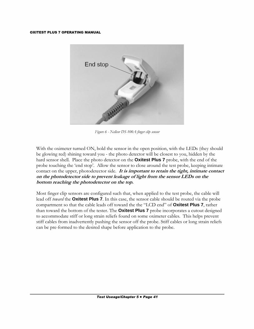
The Nellcor style sensor generally utilizes a soft, cushiony material to surround the finger, with ahard plastic or metal outer shell. Inside there is an ‘end stop’ to prevent the finger from goingtoo far into the sensor. Examples of this type include Nellcor, Nonin, andSpaceLabs/Novametrix finger clip sensors. The ‘end stop’ of the Nellcor DS-100A finger clipsensor can be seen in Figure 6.
Test Useage/Chapter 5 # Page 40
OXITEST PLUS 7 OPERATING MANUAL
Figure 6 - Nellcor DS-100A finger clip sensor
With the oximeter turned ON, hold the sensor in the open position, with the LEDs (they shouldbe glowing red) shining toward you - the photo detector will be closest to you, hidden by thehard sensor shell. Place the photo detector on the Oxitest Plus 7 probe, with the end of theprobe touching the ‘end stop’. Allow the sensor to close around the test probe, keeping intimatecontact on the upper, photodetector side. It is important to retain the tight, intimate contacton the photodetector side to prevent leakage of light from the sensor LEDs on thebottom reaching the photodetector on the top.
Most finger clip sensors are configured such that, when applied to the test probe, the cable willlead off toward the Oxitest Plus 7. In this case, the sensor cable should be routed via the probecompartment so that the cable leads off toward the the “LCD end” of Oxitest Plus 7, ratherthan toward the bottom of the tester. The Oxitest Plus 7 probe incorporates a cutout designedto accommodate stiff or long strain reliefs found on some oximeter cables. This helps preventstiff cables from inadvertently pushing the sensor off the probe. Stiff cables or long strain reliefscan be pre-formed to the desired shape before application to the probe.
Test Useage/Chapter 5 # Page 41
OXITEST PLUS 7 OPERATING MANUAL
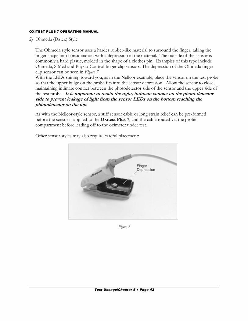
2) Ohmeda (Datex) Style
The Ohmeda style sensor uses a harder rubber-like material to surround the finger, taking thefinger shape into consideration with a depression in the material. The outside of the sensor iscommonly a hard plastic, molded in the shape of a clothes pin. Examples of this type includeOhmeda, SiMed and Physio-Control finger clip sensors. The depression of the Ohmeda fingerclip sensor can be seen in Figure 7.With the LEDs shining toward you, as in the Nellcor example, place the sensor on the test probeso that the upper bulge on the probe fits into the sensor depression. Allow the sensor to close,maintaining intimate contact between the photodetector side of the sensor and the upper side ofthe test probe. It is important to retain the tight, intimate contact on the photo-detectorside to prevent leakage of light from the sensor LEDs on the bottom reaching thephotodetector on the top.
As with the Nellcor-style sensor, a stiff sensor cable or long strain relief can be pre-formedbefore the sensor is applied to the Oxitest Plus 7, and the cable routed via the probecompartment before leading off to the oximeter under test.
Other sensor styles may also require careful placement:
Figure 7
Test Useage/Chapter 5 # Page 42
OXITEST PLUS 7 OPERATING MANUAL
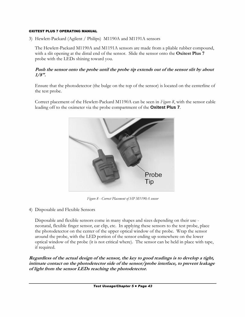
Figure 8 - Correct Placement of HP M1190A sensor
3) Hewlett-Packard (Agilent / Philips) M1190A and M1191A sensors
The Hewlett-Packard M1190A and M1191A sensors are made from a pliable rubber compound,with a slit opening at the distal end of the sensor. Slide the sensor onto the Oxitest Plus 7probe with the LEDs shining toward you.
Push the sensor onto the probe until the probe tip extends out of the sensor slit by about1/8".
Ensure that the photodetector (the bulge on the top of the sensor) is located on the centerline ofthe test probe.
Correct placement of the Hewlett-Packard M1190A can be seen in Figure 8, with the sensor cableleading off to the oximeter via the probe compartment of the Oxitest Plus 7.
4) Disposable and Flexible Sensors
Disposable and flexible sensors come in many shapes and sizes depending on their use -neonatal, flexible finger sensor, ear clip, etc. In applying these sensors to the test probe, placethe photodetector on the center of the upper optical window of the probe. Wrap the sensoraround the probe, with the LED portion of the sensor ending up somewhere on the loweroptical window of the probe (it is not critical where). The sensor can be held in place with tape,if required.
Regardless of the actual design of the sensor, the key to good readings is to develop a tight,intimate contact on the photodetector side of the sensor/probe interface, to prevent leakageof light from the sensor LEDs reaching the photodetector.
Test Useage/Chapter 5 # Page 43
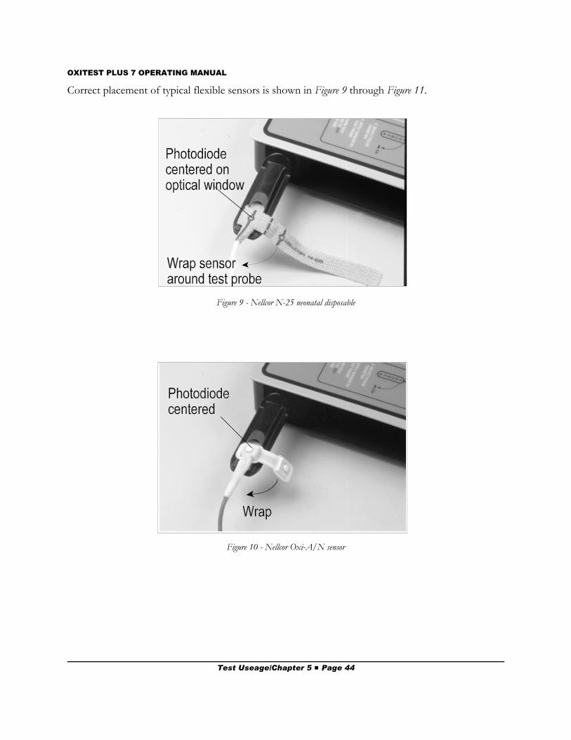
OXITEST PLUS 7 OPERATING MANUAL
Figure 10 - Nellcor Oxi-A/N sensor
Figure 9 - Nellcor N-25 neonatal disposable
Correct placement of typical flexible sensors is shown in Figure 9 through Figure 11.
Test Useage/Chapter 5 # Page 44
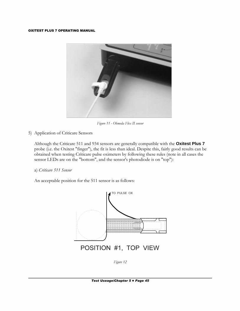
OXITEST PLUS 7 OPERATING MANUAL
Figure 12
Figure 11 - Ohmeda Flex II sensor
5) Application of Criticare Sensors
Although the Criticare 511 and 934 sensors are generally compatible with the Oxitest Plus 7probe (i.e. the Oxitest "finger"), the fit is less than ideal. Despite this, fairly good results can beobtained when testing Criticare pulse oximeters by following these rules (note in all cases thesensor LEDs are on the "bottom", and the sensor's photodiode is on "top"):
a) Criticare 511 Sensor
An acceptable position for the 511 sensor is as follows:
Test Useage/Chapter 5 # Page 45
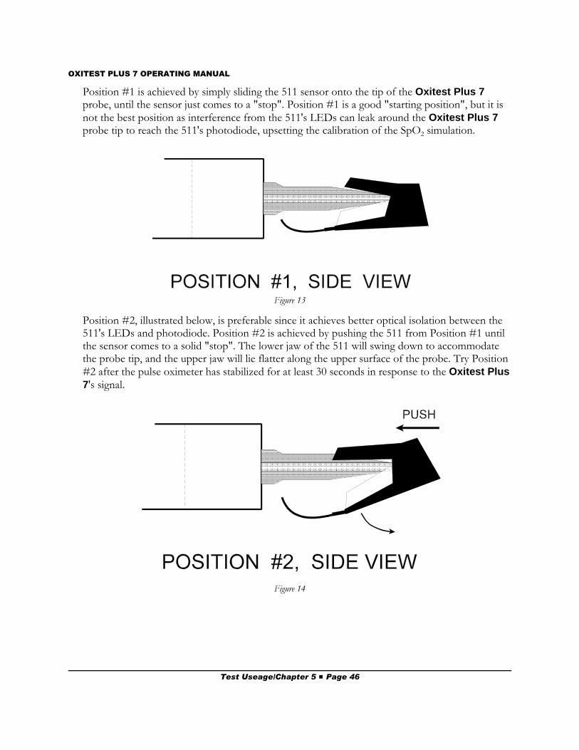
OXITEST PLUS 7 OPERATING MANUAL
Figure 13
Figure 14
Position #1 is achieved by simply sliding the 511 sensor onto the tip of the Oxitest Plus 7probe, until the sensor just comes to a "stop". Position #1 is a good "starting position", but it isnot the best position as interference from the 511's LEDs can leak around the Oxitest Plus 7probe tip to reach the 511's photodiode, upsetting the calibration of the SpO2 simulation.
Position #2, illustrated below, is preferable since it achieves better optical isolation between the511's LEDs and photodiode. Position #2 is achieved by pushing the 511 from Position #1 untilthe sensor comes to a solid "stop". The lower jaw of the 511 will swing down to accommodatethe probe tip, and the upper jaw will lie flatter along the upper surface of the probe. Try Position#2 after the pulse oximeter has stabilized for at least 30 seconds in response to the Oxitest Plus7's signal.
Test Useage/Chapter 5 # Page 46
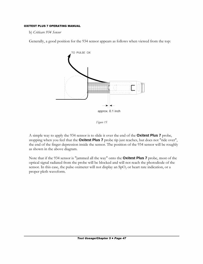
OXITEST PLUS 7 OPERATING MANUAL
Figure 15
b) Criticare 934 Sensor
Generally, a good position for the 934 sensor appears as follows when viewed from the top:
A simple way to apply the 934 sensor is to slide it over the end of the Oxitest Plus 7 probe,stopping when you feel that the Oxitest Plus 7 probe tip just reaches, but does not "ride over",the end of the finger depression inside the sensor. The position of the 934 sensor will be roughlyas shown in the above diagram.
Note that if the 934 sensor is "jammed all the way" onto the Oxitest Plus 7 probe, most of theoptical signal radiated from the probe will be blocked and will not reach the photodiode of thesensor. In this case, the pulse oximeter will not display an SpO2 or heart rate indication, or aproper pleth waveform.
Test Useage/Chapter 5 # Page 47
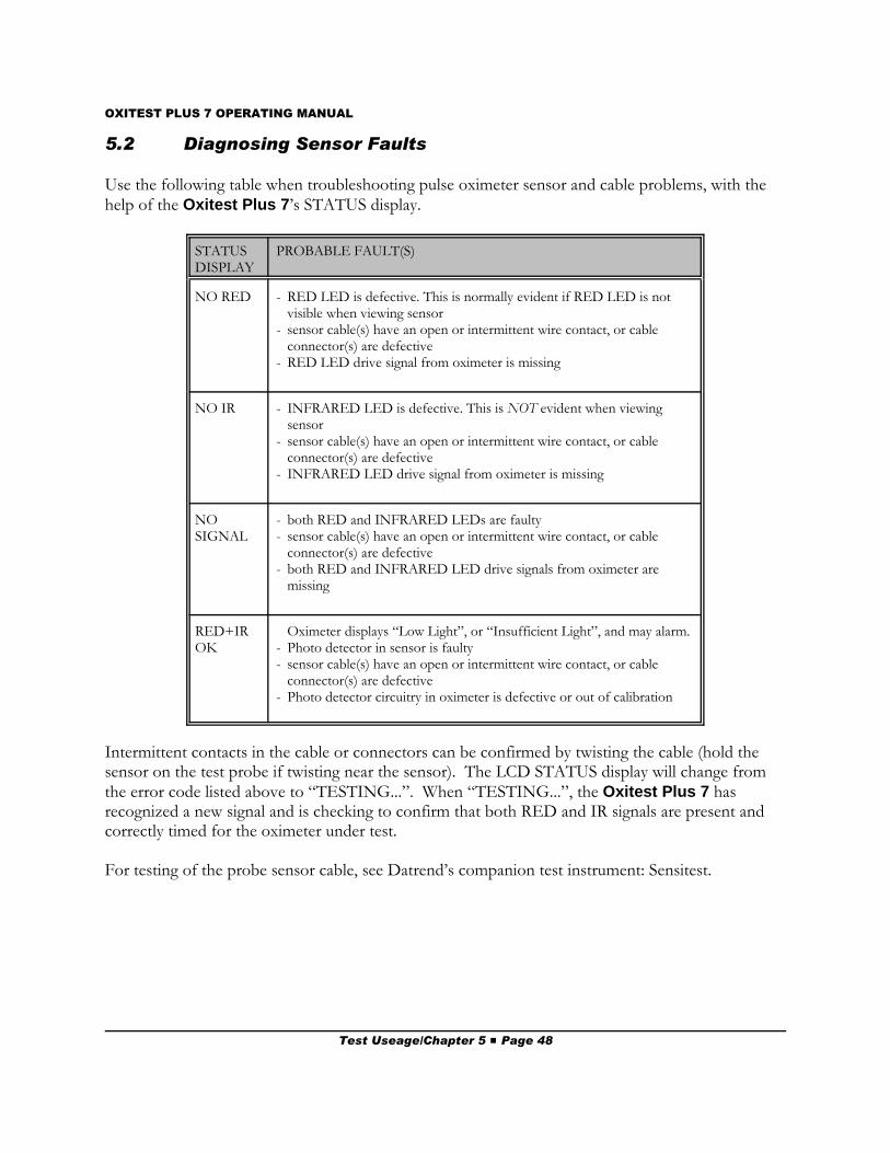
OXITEST PLUS 7 OPERATING MANUAL
5.2 Diagnosing Sensor Faults
Use the following table when troubleshooting pulse oximeter sensor and cable problems, with thehelp of the Oxitest Plus 7’s STATUS display.
STATUSDISPLAY
PROBABLE FAULT(S)
NO RED - RED LED is defective. This is normally evident if RED LED is notvisible when viewing sensor
- sensor cable(s) have an open or intermittent wire contact, or cableconnector(s) are defective
- RED LED drive signal from oximeter is missing
NO IR - INFRARED LED is defective. This is NOT evident when viewingsensor
- sensor cable(s) have an open or intermittent wire contact, or cableconnector(s) are defective
- INFRARED LED drive signal from oximeter is missing
NOSIGNAL
- both RED and INFRARED LEDs are faulty- sensor cable(s) have an open or intermittent wire contact, or cable
connector(s) are defective- both RED and INFRARED LED drive signals from oximeter are
missing
RED+IROK
Oximeter displays “Low Light”, or “Insufficient Light”, and may alarm.- Photo detector in sensor is faulty- sensor cable(s) have an open or intermittent wire contact, or cable
connector(s) are defective- Photo detector circuitry in oximeter is defective or out of calibration
Intermittent contacts in the cable or connectors can be confirmed by twisting the cable (hold thesensor on the test probe if twisting near the sensor). The LCD STATUS display will change fromthe error code listed above to “TESTING...”. When “TESTING...”, the Oxitest Plus 7 hasrecognized a new signal and is checking to confirm that both RED and IR signals are present andcorrectly timed for the oximeter under test.
For testing of the probe sensor cable, see Datrend’s companion test instrument: Sensitest.
Test Useage/Chapter 5 # Page 48
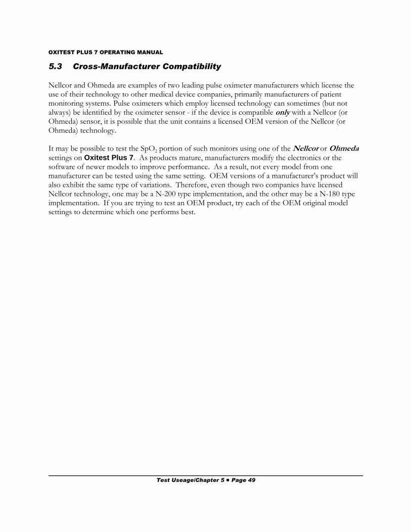
OXITEST PLUS 7 OPERATING MANUAL
5.3 Cross-Manufacturer Compatibility
Nellcor and Ohmeda are examples of two leading pulse oximeter manufacturers which license theuse of their technology to other medical device companies, primarily manufacturers of patientmonitoring systems. Pulse oximeters which employ licensed technology can sometimes (but notalways) be identified by the oximeter sensor - if the device is compatible only with a Nellcor (orOhmeda) sensor, it is possible that the unit contains a licensed OEM version of the Nellcor (orOhmeda) technology.
It may be possible to test the SpO2 portion of such monitors using one of the Nellcor or Ohmedasettings on Oxitest Plus 7. As products mature, manufacturers modify the electronics or thesoftware of newer models to improve performance. As a result, not every model from onemanufacturer can be tested using the same setting. OEM versions of a manufacturer’s product willalso exhibit the same type of variations. Therefore, even though two companies have licensedNellcor technology, one may be a N-200 type implementation, and the other may be a N-180 typeimplementation. If you are trying to test an OEM product, try each of the OEM original modelsettings to determine which one performs best.
Test Useage/Chapter 5 # Page 49

OXITEST PLUS 7 OPERATING MANUAL
Test Useage/Chapter 5 # Page 50
OXITEST PLUS 7 OPERATING MANUAL
6. Routine Maintenance6.1 Probe Cleaning
Over a period of time, a build-up of residue may be noticed on the optical windows at the probe tip.This is normal and is due to contact with dirty sensors and disposable sensors which rely onadhesive application.
To ensure the probe receives maximum light from sensors under test, and also to ensure that theoptical power emitted by the probe remains within its calibrated range, the probe should be cleanedregularly. Normally, simply wiping the optical windows with a soft cloth dampened with water is allthat is required. Detergent solutions are rarely required but acceptable at low concentrations.
DO NOT use isopropyl alcohol to clean the acrylic probe, as it will introduce stress cracksover time.
The Oxitest probe incorporates urethane, acrylic and mylar components. Therefore, underno circumstances should reactive solvents (adhesive remover, varsol, turpentine, etc) beused to clean the probe.
Maintenance/Chapter 6 # Page 51
OXITEST PLUS 7 OPERATING MANUAL
6.2 Calibration
Calibration of Oxitest Plus 7 by a Datrend Authorized Service facility is recommended on anannual basis, and is required to extend the product warranty. The basic one (1) year warranty canbe extended to a maximum of five (5) years provided that annual calibration is performed by aDatrend Authorized Service Center on an annual basis.
The Oxitest Plus 7 can only be CALIBRATED with specialized equipment and software found atDatrend authorized service facilities. This equipment allows proper adjustment of the internalelectronics of the instrument.
Independent service providers may be able to perform a performance VERIFICATION; however,they will NOT be able to perform repairs or adjustments to your Oxitest Plus 7. Use of anunauthorized facility for service and/or calibration will void your warranty.
When calibration is due, contact Datrend Customer Service to determine the authorized servicefacility nearest your location and to obtain an RMA number. In North America: 1-800-667-6557;Outside North America: (604) 291-7747; e-Mail: [email protected]
Maintenance/Chapter 6 # Page 52