Embed Size (px)
Citation preview

Mobile Networks and Applications 3 (1998) 5–32 5
MPEG-4: An object-based multimedia coding standardsupporting mobile applications
Atul Puri a and Alexandros Eleftheriadis b
a AT&T Laboratories, NSL 3-237, 100 Shultz Drive – Middletown, Red Bank, NJ 07701, USAb Department of Electrical Engineering, Columbia University, New York, NY 10027, USA
The ISO MPEG committee, after successful completion of the MPEG-1 and the MPEG-2 standards is currently working on MPEG-4,the third MPEG standard. Originally, MPEG-4 was conceived to be a standard for coding of limited complexity audio-visual scenes atvery low bit-rates; however, in July 1994, its scope was expanded to include coding of scenes as a collection of individual audio-visualobjects and enabling a range of advanced functionalities not supported by other standards. One of the key functionalities supportedby MPEG-4 is robustness in error prone environments. In general, the MPEG-4 standard provides solutions for coding of natural orsynthetic video and audio, as well as a system for multiplex/demultiplex and description of scenes in a truly flexible manner. Withfocus on the mobile multimedia functionality, we present an overview of the current status as well as the details of the MPEG-4 codingstandard. We also discuss profiles, a mechanism used for partitioning MPEG-4 into realizable subsets. Finally, plans for testing andverification of current MPEG-4 (Version 1) standard, ongoing work for MPEG-4 Version 2, as well as directions for MPEG-7, the nextMPEG standard, are briefly discussed.
1. Introduction
The need for mobile communications is ever increas-ing due to the sense of timeliness and flexibilities it offers.Increasingly, in mobile communications, a diverse set ofmedia such as speech, data, synthetic and natural imagesas well as synthetic and natural video are becoming nec-essary as mobile communications aims to supplement orreplace traditional fixed communications. In general, mul-timedia is expensive in the sense of its bandwidth require-ment, with video being highly bandwidth intensive. Effi-cient compression of video is therefore critical to makingany form of multimedia feasible. Further, the feasibility ofmobile multimedia of acceptable quality poses a significantadditional challenge. This is so because wireless channelsimpose a fairly harsh environment for multimedia commu-nications, and while the goal of compression is to squeezeredundancy out of signals to fit them on limited availablebandwidth, the requirements for robust delivery necessitatesome amount of redundancy. As in the case for wired orwireless environments, the success of multimedia terminals,products or services [8] depends on many factors, of par-ticular significance is interworking which is facilitated bystandardization.
Mobile multimedia applications can be classified intotwo primary classes, indoor and outdoor. Mobile indoorapplications are characterized by lower mobility and higherbandwidth (about 1 Mbit/s or higher) while mobile out-door applications typically tend to involve higher mobility(including higher speeds) and relatively lower bandwidths(a few kbit/s to a few tens of kbit/s or so). Of course,a number of other applications [43] in between these twoextremes also exist. Considering the limitations of the ex-isting standards when used in mobile environment, this is
an area of active research. However, the focus of this pa-per is to examine particular considerations for robustnessin the state of the art standards being developed. As apassing reference, the ISO MPEG-1 video standard [18]was primarily optimized for coding of noninterlaced videoat bit-rates of 1.2–1.5 Mbit/s and the ISO MPEG-2 videostandard [15,19] was primarily optimized for coding of in-terlaced video at bit-rates of 4–9 Mbit/s. Furthermore, theMPEG-1 standard assumed a relatively error free channeland the MPEG-2 standard, due to its generic nature, onlyconsidered the very basic error resilience techniques suchas slice synchronization, intra refresh, and a mechanism tofacilitate error concealment, motion vectors for intra codedblocks.
The currently ongoing MPEG standard (MPEG-4) [3,23,40,42] was started in 1993 with intended completion by late1998. Its original focus was modified in July 1994 fromthat of coding with high efficiency of videophone scenes atvery low bit-rates, to flexible coding of generic scenes facil-itating a number of important functionalities not supportedby other standards. Among the functionalities [3] that wereconsidered important for MPEG-4 were content-based cod-ing, universal accessibility (which includes robustness toerrors) and good coding efficiency. Further, MPEG-4 videois being optimized for bit-rates ranging from about 10 kbit/sto around 1.5 Mbit/s and is expected to be applicable toeven higher bit-rates. Incidentally, the range of bit-ratesdiscussed for MPEG-4 encompasses the bit-rates applica-ble to both indoor and oudoor mobile applications. It isworthwhile pointing out that the MPEG standards [18,19]are essentially decoding standards and thus only specifythe bitstream representation and the semantics of the de-coding process, in other words, the encoding algorithmis not standardized. Furthermore, unlike earlier standards,
Baltzer Science Publishers BV

6 A. Puri, A. Eleftheriadis / MPEG-4: An object-based multimedia coding standard
Figure 1. A high level view of an MPEG-4 terminal.
MPEG-4 is expected to consist of at least two versions –MPEG-4 Version 1 and Version 2; this paper mainly ad-dresses the MPEG-4 Version 1 standard. Details of ver-sioning of MPEG-4 are still evolving and the current statusis discussed in section 9. The specification of MPEG-4 [28,33,35], since MPEG-4 is designed to be a truly multimediastandard, goes much beyond that of previous MPEG stan-dards and addresses not only audio coding [28], video cod-ing [35] and multiplexing of coded data [33] but also codingof text/graphics and synthetic images [35] as well as flexiblerepresentation of audio-visual scene and composition [33].
Figure 1 shows a high level view of an MPEG-4 terminal[45,46,48]. We use the term “terminal” in a generic sense,including both standalone hardware as well as software run-ning on general purpose computers. A set of individuallycoded audiovisual objects (natural or synthetic) are obtainedmultiplexed from a storage or transmission medium. Theyare accompanied with scene description information, whichdescribes how these objects should be combined in spaceand time in order to form the scene intended by the contentcreator. The scene description is thus used during compo-sition and rendering, which results in individual frames oraudio samples being presented to the user. In addition, theuser may have the option to interact with the content, eitherlocally or with the source, using an upstream channel (ifavailable).
The rest of the paper is organized as follows. In sec-tion 2, we present an overview of the ITU-T video and sys-tems standards. In section 3, we review the applications, re-quirements, tests, and the organization of the MPEG-4 stan-dard. Next, section 4 discusses MPEG-4 visual tools withemphasis on error resilience tools. In section 5, MPEG-4audio standard is briefly discussed. In section 6, MPEG-4
systems is discussed in detail. In section 7, we discuss theissue of profiles, and in section 8 the plans for verifica-tion tests are presented. Section 9 discusses the work inprogress for version 2 of MPEG-4, as well as the plans forMPEG-7, the next MPEG standard. Section 10 summarizesthe key points presented in the paper.
2. Related ITU-T standards
Besides the ISO standards, the ITU-T has also devel-oped video and audio coding as well as multiplex standards.The ITU-T H.263 standard [19] is aimed at coding of videoat low bit-rates of 10–24 kbit/s and is based on the ear-lier ITU-T H.261 video standard [22] which was optimizedat 64 kbit/s (although it allows a range of 64 kbit/s to2 Mbit/s). In a general sense, the H.263 standard [23] usesthe motion compensated DCT coding framework which isalso common to the H.261, the MPEG-1 and the MPEG-2standards. This consists of partitioning each picture intomacroblocks, where a macroblock consists of 16 × 16 lu-minance (Y) block (composed of 4, 8× 8 blocks) and thecorresponding 8 × 8 chrominance blocks of Cb, and Cr.Each macroblock can be coded as intra (original signal)or as inter (prediction error signal). Spatial redundancyis exploited by DCT coding. Temporal redundancy is ex-ploited by motion compensation which is used to deter-mine the prediction error signal. Block DCT coefficientsare quantized and entropy coded. Details of H.263 includemotion compensation with accuracy of half-pixel (like thatof MPEG-1, whereas H.261 supports only integer-pixel ac-curacy) as well as optional modes such as PB-frames (asubstitute for B-pictures of MPEG-1), unrestricted motion

A. Puri, A. Eleftheriadis / MPEG-4: An object-based multimedia coding standard 7
vector, advanced 8 × 8 block prediction, and syntax basedarithmetic coding. Incidentally, these modes are optionsthat are negotiated between a decoder and an encoder. TheITU-T has continued work on further embellishing H.263by adding yet many more features and optional modes [26].
The ITU-T H.324 [27] is a multimedia communica-tions standard consisting of component standards, such asV.34 modem, H.223 multiplexer, H.245 control protocol,G.723.1 audio decoder, and H.263 (or H.261) video de-coder. H.223 is the multiplexer used to mix audio, video,data and control channels together for transmission on V.34modem. The ITU-T H.223 Annex A multiplexer has beendesigned for error prone channels and therefore features arobust packet synchronization and constant packet length.ITU-T H.324 Annex C specifies features of multimedia ter-minals operating in mobile radio environments, in terms ofdifferences with normal terminals.
3. MPEG-4 overview
MPEG-4 was originally intended for very high com-pression coding of audio-visual information at very lowbit-rates of 64 kbit/s or under. When MPEG-4 video wasstarted, it was anticipated that with continuing advances inadvanced (non-block based) coding schemes, for example,in region based and model based coding, a scheme capableof achieving very high compression, mature for standard-ization would emerge. By mid 1994, two things becameclear. First, video coding schemes that were likely to bemature within the time frame of MPEG were likely to offeronly moderate increase in compression (say, by a factor of1.5 or so) over then existing methods as compared to theoriginal goal of MPEG-4. Second, a new class of multi-media applications were emerging that required increasinglevels of functionality than that provided by any other videostandard at bit-rates in the range of 10 kbit/s to 1024 kbit/s.This lead to broadening of the original scope of MPEG-4to a larger range of bit-rates and important new functional-ities [3]. Basically, three important trends were identified,which are as follows:
• The trend towards wireless communications.
• The trend towards interactive computer applications.
• The trend towards integration of audio-visual data intoa number of applications.
The focus and scope of MPEG-4 was redefined as the in-tersection of the traditionally separate industries of telecom-munications, computer, and TV/film where audio-visual ap-plications exist. The mission and the focus statement ofMPEG-4 explaining the trends leading up to MPEG-4 andwhat can be expected in the future are documented in theMPEG-4 Proposal Package Description (PPD) document[3]. Figure 2 shows the application areas of interest toMPEG-4 arising at the intersection of the aforementionedindustries.
Figure 2. Applications areas addressed by MPEG-4 (shaded region).
To make the discussion a bit more concrete, we now pro-vide a few examples of applications or application classes[45] that the MPEG-4 standard is aimed at:
• Internet and Intranet video.
• Wireless video.
• Video databases.
• Interactive home shopping.
• Video e-mail, home movies.
• Virtual reality games, simulation and training.
With this revised understanding of the goals of MPEG-4,the MPEG-4 work was subsequently reorganized and par-titioned into the following subgroups:
• Requirements – develops requirements, application sce-narios and meaningful clustering of coding tool combi-nations for interoperability (profiles).
• Tests – develops methods for subjective and objectiveassesment and conducts tests.
• Video – develops coded representation of moving pic-tures of natural origin.
• Synthetic and Natural Hybrid Coding (SNHC) – devel-ops coded representation of synthetic audio, graphicsand moving images.
• Audio – develops coded representation of audio of nat-ural origin.
• Systems – develops techniques for multiplexing/demul-tiplexing and presentation of moving images, audio,graphics and data.
• Digital Media Integration Framework (DMIF) – devel-ops standard interfaces between digital storage media,networks, servers and clients for delivery bitstreams innetworked environments.
• Implementation studies – evaluates realizability of cod-ing tools and techniques.
On the way to becoming an International Standard,MPEG-4 undergoes a sequence of interim steps as a Work-ing Draft, a Committee Draft, a Final Committee Draft anda Draft International Standard; in table 1, we provide theschedule of these steps for MPEG-4 Version 1.

8 A. Puri, A. Eleftheriadis / MPEG-4: An object-based multimedia coding standard
Table 1MPEG-4 Version 1 workplan.
Working Draft Committee Draft Final Committee Draft International InternationalDraft Standard Standard
November 1996 November 1997 July 1998 November 1998 January 1999
Table 2Functionalities expected to be supported by MPEG-4 Version 1.
Content-based interactivity
Hybrid natural and synthetic data coding: The ability to code and manipulate natural and synthetic objects in a scene including decoder controllablemethods of compositing of synthetic data with ordinary video and audio, allowing for interactivity.
Improved temporal random access: The ability to efficiently access randomly in a limited time and with fine resolution parts (frames or objects) withinan audio-visual sequence. This also includes the requirement for conventional random access.
Content-based manipulation and bitstream editing: The ability to provide manipulation of contents and editing of audio-visual bitstreams without therequirement for transcoding.
Universal access
Robustness in error prone environments: The capability to allow robust access to applications over a variety of wireless and wired networks and storagemedia. Sufficient robustness is required, especially, for low bit-rate applications under severe error conditions.
Content-based scalability: The ability to achieve scalability with fine granularity in spatial, temporal or amplitude resolution, quality or complexity.Content based scaling of audio-visual information requires these scalabilities.
Compression
Improved coding efficiency: The ability to provide subjectively better audio-visual quality at bit-rates compared to existing or emerging video codingstandards.
The MPEG-4 standard (ISO/IEC 14496) [46] is plannedto consist of the following basic parts. Other parts may beadded when the need is identified.
• ISO/IEC 14496-1: Systems.
• ISO/IEC 14496-2: Visual (Natural and Synthetic Video).
• ISO/IEC 14496-3: Audio (Natural and Synthetic Au-dio).
• ISO/IEC 14496-4: Conformance.
• ISO/IEC 14496-5: Software.
• ISO/IEC 14496-6: DMIF.
3.1. MPEG-4 functionalities and requirements
Now that we have some idea of the type of applicationsMPEG-4 is aimed for, we clarify the three basic functional-ity classes [3,15] that the MPEG-4 standard is addressing.They are as follows:
• Content-based interactivity allows the ability to interactwith objects in a scene. Currently such interaction istypically only possible for synthetic objects; extendingsuch interaction to natural and hybrid synthetic/naturalobjects is important to enable new audio-visual applica-tions.
• Universal accessibility means the ability to access audio-visual data over a diverse range of storage and trans-mission media. Due to increasing trend toward mobilecommunications, it is important that access be availableto applications via wireless networks. Thus acceptable
performance is needed over error-prone environmentsand at low bit-rates.
• Improved compression is needed to allow increase in ef-ficiency in transmission or decrease in amount of storagerequired. For low bit-rate applications, high compres-sion is very important to enable new applications.
Although we have looked at general classes of function-alities being addressed by MPEG-4 it is desirable to look atspecific functionalities that MPEG-4 Version 1 expects tooffer; in table 2 we now show a list of 6 such functionalities[3,6,15] and show their clustering into three functionalityclasses.
Besides the new functionalities, MPEG-4 is also sup-porting the basic functionalities such as synchronization ofaudio and video, auxilliary data streams capability, multi-point capability, low delay mode, coding of a variety ofaudio types, interoperability with other audio-visual sys-tems, support for interactivity, ability to efficiently operatein the 9.6 to 1024 kbit/s range, ability to operate in differ-ent media environments, and the ability to operate in lowcomplexity mode.
To keep up with marketplace needs for practical timelystandards and to follow the evolving trends, the require-ments collection process for MPEG-4 is kept flexible. Themajor restructuring of MPEG-4 effort in July 1994 to ex-pand its scope was a response to the evolving trends inthe marketplace. Evaluating requirements for MPEG-4 isan ongoing exercise that uses both top down (common re-quirements of related applications) and bottom up approach(related functions provided by a tool, which may be needed

A. Puri, A. Eleftheriadis / MPEG-4: An object-based multimedia coding standard 9
Table 3List of MPEG-4 first evaluation formal tests and their explanation.
Compression
Class A sequences at 10, 24 and 48 kbit/s: Coding to achieve the highest compression efficiency. Input video resolution is CCIR-601 and althoughany spatial and temporal resolution can be used for coding, the display format is CIF on a windowed display. The test method employed is SS.
Class B sequences at 24, 48 and 112 kbit/s: Coding to achieve the highest compression efficiency. Input video resolution is CCIR-601 and althoughany combination of spatial and temporal resolutions can be used for coding, the display format is CIF on a windowed display. The test methodemployed is SS.
Class C sequences at 320, 512 and 1024 kbit/s: Coding to achieve the highest compression efficiency. Input video resolution is CCIR-601 andalthough any combination of spatial and temporal resolution can be used for coding, the display format is CCIR-601 on a full display. The test methodemployed is DSCQS.
Error robustness
Error resilience at 24 kbit/s for Class A, 48 kbit/s for Class B, and 512 kbit/s for Class C: Test with high random bit error rate (BER) of 10−3,multiple burst errors with 3 bursts of errors with 50% BER within a burst, and a combination of high random bit errors and multiple burst errors. Thedisplay format for Class A and Class B sequences is CIF on a windowed display and for Class C sequences is CCIR-601 on full display. The testmethod employed for Class A and Class B is SS and that for Class C is DSCQS.
Error recovery at 24 kbit/s for Class A, 48 kbit/s for Class B and 512 kbit/s for Class C: Test with long burst errors of 50% BER within a burst anda burst length of 1 to 2 seconds. Display format for Class A and Class B is CIF on a windowed display and Class C is CCIR-601 on full display. Thetest method employed for Class A and Class B is SS and that for Class C is DSCQS.
Scalability
Object scalability at 48 kbit/s for Class A, 320 kbit/s for Class E, and 1024 kbit/s for Class B/C sequences: Coding to permit dropping of specifiedobjects resulting in remaining scene at lower then total bit-rate; each object and the remaining scene is evaluated separately by experts. The displayformat for Class A is CIF on a windowed display and for Class B/C and Class E is CCIR-601 on a full display. The test method employed for ClassA is SS, for Class B/C is DSCQS, and for Class E is DSIS.
Spatial scalability at 48 kbit/s for Class A, and 1024 kbit/s for Class B/C/E sequences: Coding of a scene as two spatial layers with each layer usinghalf of the total bit-rate, however, full flexibility in choice of spatial resolution of objects in each layer is allowed. The display format for Class A isCIF on a windowed display and that for Class B/C/E is CCIR-601 on a full display. The test method employed for Class A is SS, and that for ClassB/C/E is DSCQS.
Temporal scalability at 48 kbit/s for Class A, and 1024 kbit/s for Class B/C/E sequences: Coding of a scene as two temporal layers with each layerusing half of the total bit-rate, however, full flexibility in choice of temporal resolution of objects in each layer is allowed. The display format forClass A is CIF on a windowed display and that for Class B/C/E is CCIR-601 on a full display.
in various applications). The collected requirements areclustered and translated into general directions for codingmethods/tools development for individual subgroups suchas Video, Audio, SNHC, Systems and DMIF. Finally, takinginto account requirements of similar applications, a cluster-ing of tools into profiles takes place (see section 7).
3.2. Tests and evaluation
We now discuss the testing and evaluation that tookplace in the competitive phase to determine the potentialof the proposed technologies for MPEG-4. We also indi-cate how the outcome of tests and evaluation was used toinitiate the collaborative phase.
3.2.1. Video testsThe competitive phase of MPEG-4 video began with
an open call for proposals in November 1994 (and sub-sequently revised [6]), inviting technical proposals for thefirst testing and evaluation [4] which took place in Octo-ber 1995. A proposal package description (PPD) and atest/evaluation procedures document was finalized by July1995. Some functionalities were formally tested while theothers were informally evaluated by experts.
Video scenes are classified from relatively simple tomore complex by categorizing them into three classes:Class A, Class B and Class C. Two other classes of scenes,Class D (stereoscopic) and Class E (hybrid of natural andsynthetic) were additionally defined. Many of the testscenes were presegmented (semiautomatically) into objectsand a segmentation mask was provided along with testscenes. Also, since a variety of functionalities had to betested, three type of tests were devised: Single Stimulus(SS), Double Stimulus Impairment Scale (DSIS) and Dou-ble Stimulus Continuous Quality Scale (DSCQS).
Table 3 summarizes the list of formal subjective tests[4], an explanation of each test and the type of methodemployed for each test.
The results [30] of tests revealed that DCT based codingperformed reasonably well. Furthermore, it seemed pos-sible to code shape of objects efficiently allowing objectbased functionalities. A collaborative effort was begun byfirst defining a set of core experiments (in November 1995)and soon after a Verification Model, VM (in January 1996)as the basis for further experimentation. Further, tentativeplans were also made for a second test for verification ofadopted coding algorithms/tools by mid 1997.

10 A. Puri, A. Eleftheriadis / MPEG-4: An object-based multimedia coding standard
3.2.2. Audio testsThe MPEG-4 Audio also underwent subjective testing,
similar to video. Three classes of audio test sequences,Class A, B and C were identified:
• Class A: Single source sequences consisting of a cleanrecording of a solo instrument.
• Class B: Single source with background sequences con-sisting of a person speaking with background noise.
• Class C: Complex sequences consisting of an orchestralrecording.
All sequences were originally sampled at 48 kHz with16 bits/sample and were monophonic in nature. For gener-ating reference formats, filters were specified to downsam-ple them to 24, 16 and 8 kHz. A number of bit-rates suchas 2, 6, 16, 24, 40 and 64 kbit/s were selected for testingof audio/speech. The first three bit-rates are obviously onlysuitable for speech material. The audio test procedures usedwere as defined in ITU-R Recommendation 814.
The proposals submitted for testing included variantsof MPEG-2 Advanced Audio Coding (AAC), variations ofMPEG-1 audio coding and new coding schemes. For spe-cific bit-rates, some candidates outperformed the referencecoding schemes, although for all combinations tested, nosingle scheme was the clear winner. After subjective test-ing, the collaborative work started and an initial MPEG-4Audio VM was developed. The MPEG-4 Audio develop-ment underwent a core experiments process similar to thatof the MPEG-4 Video development process.
3.2.3. SNHC testsThe SNHC group started its work much later than the
video group. Its focus was primarily on coding for storageand communication of 2D and 3D scenes involving syn-thetic images, sounds, and animated geometry and its inte-gration into scenes that contain coded natural images/videoand sound. Further, it was sought that the coded represen-tation should also facilitate various forms of interactions.
In the SNHC call for proposals [29] and PPD [30], pro-posals in the areas of efficient compression and simplifi-cation of synthetic data, parameterized animated models,new primitive operations for compositing of natural andhybrid objects, scalability, real-time interactivity with syn-thetic/hybrid environments, modeling of timing and syn-chronization, synthetic audio, etc., were sought.
In the competitive phase, for the purpose of standard-ized evaluation, a database of test data set was established.The actual evaluation of proposals by a group of expertstook place in September 1996. The evaluation criteria wasbased on the functionality addressed such as coding ef-ficiency, quality of decoded model, real-time interactivity,anticipated performance in future, and implementation cost.After the evaluation, the collaborative phase was begun bydefining a verification model (VM).
3.3. Video development
Video development was started by identifying a numberof needed tools and the options available for each tool aswell as a reference framework. A total of about 40 coreexperiments were defined by January 1996 and were cate-gorized for evaluation by the following 4 ad hoc groups:
• Coding efficiency – prediction, frame texture coding,quantization and rate control.
• Shape and object texture coding – binary and grey scaleshape coding, object texture coding.
• Robust coding – error resilience and error concealment.
• Multifunctional coding – bandwidth and complexityscalability, object manipulation, post processing.
A reference coding framework known as the first Veri-fication Model (VM1) was released on 24th January 1996.It supported the following features:
• Coding of arbitrary shaped objects using Video ObjectPlanes (VOPs).
• Coding of binary and grey scale shape of arbitraryshaped objects.
• Padding of pixels to fill the region outside of an objectto full blocks for motion compensation and DCT.
• Macroblock based motion-texture (motion compensatedDCT) coding derived from H.263.
• A mode allowing separation of motion and texture datafor increased error resilience.
During the March 1996 MPEG meeting, a number ofadditional features were added to VM1 and thus VM2 [29]was released on 29th March 1996. The additional featureswere as follows:
• Bidirectional VOPs derived from combination of H.263PB-frames mode and MPEG-1/2 B-pictures.
• DC coefficients prediction for intra macroblocks as perMPEG-1/2.
• Extended motion vector range.
• Quantization visibility matrices as per MPEG-1/2.
The process of iterative development and refinement ofvideo VM’s via core experiments has continued and therehave been seven iterations on the first VM. At the October1997 meeting, a number of mature tools from VM8 wereaccepted for MPEG-4 Video Version 1 for the Commit-tee Draft. The remaining tools as well as some new toolsare being considered for MPEG-4 Video Version 2. In sec-tion 4, we describe the basic coding methods formed by thetools accepted for the MPEG-4 Video Version 1 standard.
3.4. Audio development
The MPEG-4 Audio coding effort occurred in parallelwith the MPEG-2 AAC (formerly, Non-Backward Com-patible (NBC)) coding effort. The MPEG-2 standard origi-

A. Puri, A. Eleftheriadis / MPEG-4: An object-based multimedia coding standard 11
nally had an audio coding mode called backward compati-ble (BC) mode which as the name suggests was backwardcompatible with MPEG-1 audio coding. However, at alate stage in MPEG-2 it was discovered that the BC audiocoding was rather inefficient compared to non compatiblesolutions and thus work on NBC mode was begun and over-lapped with the MPEG-4 schedule. The NBC mode wasrenamed AAC and became a new part of MPEG-2 achiev-ing International Standard status in April 1997 (although ithad reached a mature status in mid 1996).
Towards the very low bit-rate end a valid question to askis why not use the existing ITU-T coders? As an answerto this question, the ITU-T speech coders currently oper-ate at 6.3/5.3 kbit/s (G.723), 8 kbit/s (G.729), 16 kbit/s(G.728), 32 kbit/s (G.721) 48/56/64 kbit/s (G.722). Incomparison, MPEG-4 speech coding is being designed tooperate at bit rates between 2–24 kbit/s for the 8 kHz modeand 14–24 kbit/s for the 16 kHz mode, whereas ITU-Tcoders do not operate at bit-rates as low 2 kbit/s for the8 kHz mode, or 14–24 kbit/s for the 16 kHz mode. Fur-thermore, MPEG-4 speech coders are being designed forbit-rate scalability, complexity scalability and multi-bit-rateoperation from 2–24 kbit/s. The coding quality of the coderis comparable to that of the ITU coder at corresponding bit-rates but the MPEG-4 speech coder can operate down to2 kbit/s. The quality at 2 kbit/s is “communication qual-ity” and could be used for usual conversation, performingbetter than the FS1016 4.8 kbit/s coder.
Therefore, the MPEG-4 Audio VMs have targeted bit-rates from 2 kbit/s to 64 kbit/s; a number of codingschemes are used to cover portions of this range. Besidescoding efficiency, content based coding of audio objects andscalability are being investigated. There have been a totalof four iterations of audio VM, from VM1 to VM4; the lastVM was released in July 1997. In fact, the more maturetools of Audio VM3 have been accepted for the audio part[28] of the MPEG-4 Version 1 standard.
In section 5, we briefly discuss the basic coding tech-niques accepted for part 3 of the MPEG-4 Version 1 stan-dard.
3.5. SNHC development
There have been a total of four iterations of SNHC VM,from VM1 to VM4; the last VM was released in July 1997.In fact, the more mature tools of SNHC VM3 have beenaccepted for the visual part of the MPEG-4 Version 1 stan-dard; the remaining tools have been left in VM4 for con-sideration for the next version of MPEG-4.
In section 4 we describe the SNHC tools expected tobe included in the visual part of the MPEG-4 Version 1standard. In section 5, we discuss the SNHC tools expectedto be included in the audio part of the MPEG-4 Version 1standard.
Figure 3. MPEG-2 Systems.
3.6. Systems development
The Systems layer in MPEG has been traditionally re-sponsible for integrating media components into a singlesystem, providing multiplexing and synchronization ser-vices for audio and video streams.
In MPEG-2 [3,15], for example, these are the primaryfunctionalities, and were designed for two types of transportfacilities. The first, Program Stream, is intended for reliablemedia such as storage devices, and can only carry a singleprogram (combinations of synchronized audio and videostreams). It also provided backwards compatibility withMPEG-1 [23]. The second, Transport Stream, is intendedfor potentially unreliable media and can carry multiple pro-grams. This is shown in figure 3. The object-based natureof MPEG-4 necessitates a much more complex Systemslayer since, in addition to still addressing multiplexing andsynchronization, it must also provide for ways to combinesimple audio or visual objects into meaningful scenes.
Considering the object-based nature of MPEG-4, a keyrequirement from the System part is the capability to com-bine individual audiovisual objects in scenes. In late 1995,this was accomplished by using Java [14]. Issues of perfor-mance and compliance soon arose. Clearly, it is essentialfor a content creator to be assured that the content generatedwill be shown in an identical way (or nearly so) regard-less of the terminal used, if both such terminals comply tothe standard. A three-step approach was adopted, involv-ing three different flexibility levels, as shown in figure 4.In level 0, no programmability was allowed. In level 1,facilities were provided to combine different tools into al-gorithms, while in level 2 even individual tools were con-sidered as targets for programmable behavior. The groupwas also renamed to MPEG-4 System and Description Lan-guages (MSDL), separating system and syntactic descrip-tion [5]. After further examination, in late 1996 it wasdecided that any meaningful operation of level 1 would re-quire the complexity of implementing a level 2 system, andhence this intermediate level was eliminated.
The group subsequently focused on a parametric (bit-stream oriented, non-programmable) solution for describ-ing how objects should be combined together. Using the

12 A. Puri, A. Eleftheriadis / MPEG-4: An object-based multimedia coding standard
Figure 4. Evolution of MPEG-4 systems architecture (1996).
above figure, that would be a level 0 design. The groupalso reverted to the use of the traditional term “Systems”,reflecting the varied components that it addresses. A pro-grammable approach is still being considered and is dis-cussed in more detail in section 6.2.4.
In addition to the overall architectural issues, the issueof multiplexing in MPEG-4 also underwent several stagesof evolution. The H.223 Annex A multiplexer was used asa basis, including error protection tools (interleaving andARQ). A key requirement [48], however, for MPEG-4 wasthe need to be transport-independent. As a result, servicesthat belong to a transport layer were subsequently removedfrom the set of specified tools, so that efficient implemen-tation of MPEG-4 systems could be performed in a verybroad range of environment (broadcast, ATM, IP, and wire-less).
3.7. DMIF development
At a recent MPEG meeting, the significance of the DMIFactivity has been recognized and DMIF has been given thestatus of a new group [7]. Previously, DMIF was an adhoc group operating under the systems group. The charterof the DMIF group is to develop standards for interfacesbetween Digital Storage Media (DSM), networks, serversand clients for the purpose of managing DSM resources andcontrolling the delivery of MPEG bitstreams and associateddata. The ongoing work of this group is expected to resultin part 6 of the MPEG-4 standard.
4. MPEG-4 visual
The ongoing work on MPEG-4 visual standard specifi-cation [35] consists of tools and methods from two majorareas – coding of (natural) video and coding of syntheticvideo (visual part of the SNHC work). We address boththese areas; in sections 4.1–4.4 we discuss tools and tech-niques relevant to natural video coding and in sections 4.5–4.7 we discuss tools and techniques relevant to syntheticvideo coding.
4.1. MPEG-4 video coding basics
In this and the next section, we describe the coding meth-ods and tools of MPEG-4 video; the encoding description isborrowed from Video VM7 [37], the decoding descriptionfollows [35]. An input video sequence can be defined as asequence of related snapshots or pictures, separated in time.In MPEG-4, each picture is considered as consisting of tem-poral instances of objects that undergo a variety of changessuch as translations, rotations, scaling, brightness and colorvariations etc. Moreover, new objects enter a scene and/orexisting objects depart, leading to the presence of temporalinstances of certain objects only in certain pictures. Some-times, scene change occurs, and thus the entire scene mayeither get reorganized or replaced by a new scene. Manyof MPEG-4 functionalities require access not only to entiresequence of pictures, but to an entire object, and further, notonly to individual pictures, but also to temporal instancesof these objects within a picture. A temporal instance ofa video object can be thought of as a snapshot of arbitraryshaped object that occurs within a picture, such that like apicture, it is intended to be an access unit, and, unlike apicture, it is expected to have a semantic meaning.
The concept of Video Objects (VOs) and their tempo-ral instances, Video Object Planes (VOPs) is central toMPEG-4 video. A VOP can be fully described by tex-ture variations (a set of luminance and chrominance values)and (explicit or implicit) shape representation. In naturalscenes, VOPs are obtained by semi-automatic or automaticsegmentation, and the resulting shape information can berepresented as a binary shape mask. On the other hand, forhybrid (of natural and synthetic) scenes generated by bluescreen composition, shape information is represented by an8-bit component, referred to as grey scale shape. In fig-ure 5, we show the decomposition of a picture into a numberof separate VOPs. The scene consists of two objects (headand shoulders view of a human, and a logo) and the back-ground. The objects are segmented by semi-automatic orautomatic means and are referred to as VOP1 and VOP2,while the background without these objects is referred toas VOP0. Each picture in the sequence is segmented intoVOPs in this manner. Thus, a segmented sequence containsa set of VOP0s, a set of VOP1s and a set of VOP2s, in otherwords, in our example, a segmented sequence consists ofVO0, VO1 and VO2.
Each VO is encoded separately and multiplexed to forma bitstream that users can access and manipulate (cut, paste,etc.). The encoder sends together with VOs, informationabout scene composition to indicate where and when VOPsof a VO are to be displayed. This information is howeveroptional and may be ignored at the decoder which may useuser-specified information about composition.
In figure 6 we show a high level logical structure ofa VO based coder. Its main components are VO Seg-menter/Formatter, VO Encoders, Systems Multiplexer Sys-tems Demultiplexer, VO Decoders and VO Compositor.VO Segmenter segments the input scene into VOs for en-

A. Puri, A. Eleftheriadis / MPEG-4: An object-based multimedia coding standard 13
Figure 5. Semantic segmentation of a picture in to VOPs.
Figure 6. Logical structure of Video Object based codec of MPEG-4video.
Figure 7. An example prediction structure when using I-, P- and B-VOPs.
coding by VO Encoders. The coded data of various VOs ismultiplexed for storage or transmission, following which itis demultiplexed and decoded by VO decoders and offeredto compositer, which renders the decoded scene.
To see how coding takes place in a video object en-coder, consider a sequence of VOPs. Extending the con-cept of intra (I-) pictures, predictive (P-) and bidirection-ally predictive (B-) pictures of MPEG-1/2 to VOPs, I-VOP,P-VOP and B-VOP result. If two consecutive B-VOPsare used between a pair of reference VOPs (I- or a P-VOPs), the resulting coding structure is as shown in fig-ure 7.
In figure 8 we show the internal structure of the VMbased encoder which codes a number of VOs of a scene.Its main components are: Motion Coder, Texture and ShapeCoder. The Motion Coder uses macroblock and block mo-tion estimation and compensation, similar to H.263 andMPEG-1/2 but modified to work with arbitrary shapes. TheTexture Coder uses block DCT coding based on H.263 andMPEG-1/2 but much better optimized; further it is alsoadapted to work with arbitrary shapes. An entirely newcomponent is the Shape Coder. The partial data of VOs(such as VOPs) is buffered and sent to the Systems Multi-plexer.
Figure 8. Detailed structure of video objects encoder.
Figure 9. Class hierarchy for structuring coded video data.
From a top-down perspective, the organization of codedMPEG-4 Video data can be described by the following classhierarchy:
• VideoSession: A Video Session represents the highestlevel in the class hierarchy and simply consists of anordered collection of Video Objects. This class has onlybeen a place holder for video VM and core experimentswork and, since composition of objects is now handledby systems, it is not needed.
• VideoObject: A Video Object (2D + time) represents acomplete scene or a portion of a scene with a semanticmeaning.
• VideoObjectLayer (VOL): A Video Object Layer (2D+time) represents various instantiations of an Video Ob-ject. For instance, different VOLs may correspond todifferent layers, such as in the case of scalability.
• GroupOfVideoObjectPlanes (GOV): Group of VideoObject Planes are optional entities and are essentiallyaccess units for editing, tune-in or synchronization.
• VideoObjectPlane (VOP): A Video Object Plane repre-sents a snap shot in time of a Video Object. A simpleexample may be an entire frame or a portion of a frame.Different coding methods from MPEG-1/2 such as intra(I-) coding, predictive (P-) coding and bidirectionallypredictive (B-) coding can now be applied to VOPs.
The class hierarchy used for representation of coded bit-stream described above is shown by the tree structure offigure 9.

14 A. Puri, A. Eleftheriadis / MPEG-4: An object-based multimedia coding standard
Figure 10. A VOP in a bounding box.
4.2. Video coding details
4.2.1. Binary shape coderCompared to other standards, the ability to represent ar-
bitrary shapes is an important capability of the MPEG-4video standard. In general, shape representation can beeither implicit (based on chroma-key and texture coding)or explicit (boundary coding separate from texture coding).Implicit shape representation, although it offers less encod-ing flexibility, can result in quite usable shapes while beingrelatively simple and computationally inexpensive. Explicitshape representation although it can offer flexible encodingand somewhat better quality shapes, it is more complex andcomputationally expensive. Regardless of the implications,the explicit shape representation was chosen in MPEG-4video; we now briefly describe the essence of this method[35,37] without its many details.
For each VO given as a sequence of VOPs of arbitraryshapes, the corresponding sequence of binary alpha planesis assumed to be known (generated via segmentation orvia chroma-key). For the binary alpha plane, a rectangularbounding box enclosing the shape to coded is formed suchthat its horizontal and vertical dimensions are multiples of16 pixels (macroblock size). For efficient coding, it is im-portant to minimize the number of macroblocks containedin the bounding box. The pixels on the boundaries or insidethe object are assigned a value of 255 and are consideredopaque while the pixels outside the object but inside thebounding box are considered transparent and are assigneda value of 0. If a 16 × 16 block structure is overlaid onthe bounding box, three types of binary alpha blocks exist:completely transparent, completely opaque, and partiallytransparent (or partially opaque). Figure 10 shows an exam-ple of an arbitrary shape VOP with a bounding box and theoverlaid 16× 16 block structure; the opaque area is shownshaded whereas the transparent area is shown unshaded.
Coding of each 16 × 16 binary alpha block represent-ing shape can be performed either lossy or losslessly. Thedegree of lossiness in coding the shape of a video objectis controlled by a threshold which can take values of 0,16, 32, 64, . . . , 256. The higher the value of this thresh-old, the more lossy the shape representation; a zero valueimplies lossless shape coding. Within the global bound ofspecified lossiness, local control, if needed, can be exertedby selecting a maximum subsampling factor on a 16× 16binary alpha that results in just acceptable distortion. The
(a) (b)
Figure 11. Pixel templates used for (a) intra and (b) inter context de-termination of a binary alpha block (BAB). Pixel to be coded is marked
with‘?’.
estimation of this factor is iterative and consists of usingthe same subsampling factor in both dimensions and de-termining the acceptability of resulting shape quality. Tobe specific, a 4:1 downsampled binary alpha block is usedfirst and if the shape errors are higher than acceptable, a2:1 downsampled binary alpha block is used next, againif it is found unacceptable, an unsubsampled binary alphablock is used.
Further, each binary alpha block can be coded in intramode or in inter mode, similar to coding of texture mac-roblocks. In intra mode, no explicit prediction is performed.In inter mode, shape information is differenced with respectto the prediction obtained using a motion vector, the result-ing binary shape prediction error may or may not be coded.The motion vector of a binary alpha block is estimated atthe encoder by first finding a suitable initial candidate fromamong the motion vectors of 3 previously decoded sur-rounding texture macroblocks as well as the 3 previouslydecoded surrounding shape binary alpha blocks. Next, theinitial candidate is either accepted as the shape motion vec-tor, or is used as the starting basis for a new motion vectorsearch, depending on if the resulting prediction errors of theinitial motion vectors are below a threshold. The motionvector is coded differentially and included in the bitstream.Following this procedure, a binary alpha block is assigneda mode from among the following choices:
1. Zero differential motion vector and no inter shape up-date.
2. Nonzero differential motion vector and no inter shapeupdate.
3. Transparent.
4. Opaque.
5. Intra shape.
6. Zero differential motion vector and inter shape update.
7. Nonzero differential motion vector and inter shape up-date.
Depending on the coding mode and whether it is anI-, P- or B-VOP, a variable length codeword is assignedidentifying the coding type of the binary alpha block. The

A. Puri, A. Eleftheriadis / MPEG-4: An object-based multimedia coding standard 15
entropy coding of shape data is performed by using thecontext information determined on a pixel basis to drivean adaptive arithmetic coder. The pixels of binary alphablock are raster scanned, however, a binary alpha blockmaybe transposed. Next, a context number is determinedand is used to index a probability table, and further, theindexed probability is used to drive the arithmetic coder.To determine the context, different templates of surroundingpixels are used for intra and inter coded binary alpha blocks,as shown in figure 11.
The decoding of binary alpha block follows the inversesequence of operations with the exception of encoder spe-cific tasks such as motion estimation, subsampling factordetermination, mode decision, etc., which are readily ex-tracted from the coded bitstream.
4.2.2. Motion CoderThe Motion Coder [35,37] consists of a Motion Esti-
mator, Motion Compensator, Previous/Next VOPs Storeand Motion Vector (MV) Predictor and Coder. In caseof P-VOPs, Motion Estimator computes motion vectorsusing the current VOP and temporally previous recon-structed VOP available from the Previous ReconstructedVOPs Store. In case of B-VOPs, Motion Estimator com-putes motion vectors using the current VOP and tempo-rally previous reconstructed VOP from the Previous Re-constructed VOP Store, as well as, the current VOP andtemporally next VOP from the Next Reconstructed VOPStore. The Motion Compensator uses these motion vectorsto compute motion compensated prediction signal using thetemporally previous reconstructed version of the same VOP(reference VOP). The MV Predictor and Coder generatesprediction for the MV to be coded. We now discuss thedetails of padding needed for motion compensation of arbi-trary shaped VOPs, as well as the various modes of motioncompensation allowed.
In the reference VOP, based on its shape information,two types of macroblocks require padding, those that lie onthe boundary and (depending on encoding choice, some orall of) the other that lie outside of the VOP. Macroblocksthat lie on the VOP boundary are padded by first replicatingthe boundary pixels in the horizontal direction, followedby replicating the boundary pixels in the vertical directionmaking sure that if a pixel can be assigned a value by bothhorizontal and vertical padding, it is assigned an averagevalue. Next, the macroblocks that lie outside of the VOPare padded by extending the boundary macroblock pixels,up, down, left and right, and averaging wherever a pixelis assigned a value from more than one directions. Theprocessing for the previous step can be reduced by onlypadding macroblocks that are outside of the VOP but rightnext to the boundary pixels.
The basic motion estimation and compensation is per-formed on 16× 16 luminance block of a macroblock. Themotion vector is specified to half-pixel accuracy. The mo-tion estimation is performed by full search to integer pixelaccuracy vector and using it as the initial estimate, a half
pixel search is performed around it. The luminance blockmotion vector is scaled by a factor of 2 for each compo-nent and rounded for use on 8 × 8 chrominance blocks.MPEG-4 video, like H.263, supports an unrestricted rangefor motion estimation and compensation. Basically, motionvectors are allowed to point out of the VOP bounding box,by extending the reference VOP bounding box in all fourdirections. Further, a larger range of motion vectors is sup-ported for motion vector coding in MPEG-4 as comparedto H.263.
Often a single motion vector for a 16 × 16 luminanceblock does not reduce the prediction errors sufficiently orwhen dealing with boundary macroblocks, motion vectorscan be sent for individual 8× 8 blocks. Further, the 8× 8block motion vectors are used to generate overlapped blockmotion compensated prediction. Both the 8×8 block mo-tion compensation and overlapped motion compensated pre-diction are referred to as advanced prediction in H.263and are adapted in MPEG-4 to work with arbitrary shapedVOPs.
An intra versus inter coding decision is performed todetermine if motion vector(s) need to be sent for the mac-roblock being coded; further, a decision is also performedto determine if 16× 16 or 8× 8 block motion vectors willbe sent for the macroblock being coded. All motion vec-tors are coded differentially using median of neighboringthree decoded macroblock (or block in case of 8×8 coding)motion vectors as the prediction.
As mentioned earlier, a B-VOP is a VOP which is codedbidirectionally. For example, macroblocks in a B-VOP canbe predicted using the forward, the backward or both usingthe forward and backward motion vectors; this has similar-ities to MPEG-1/2 in which B-pictures can use such motionvectors. However, MPEG-4 video also supports an H.263based mode for motion compensation, referred to as thedirect mode. In direct mode, the motion vector for a mac-roblock in a B-VOP is obtained by scaling of the P-VOPmotion vector, and further correcting it by a small (delta)motion vector. The actual motion compensation mode to beused for a macroblock is decided taking into account themotion compensated prediction errors produced by vari-ous choices and the coding overhead of any additional mo-tion vectors. All motion vectors (except delta) are codeddifferentially with respect to motion vectors of the sametype.
MPEG-4 also supports efficient coding of interlacedvideo. It combines the macroblock based frame/field mo-tion compensation of MPEG-2 with the normal motioncompensation of MPEG-4, resulting in overall improvedmotion compensation. Furthermore, it allows motion com-pensation of arbitrary shaped VOPs of interlaced videowhereas MPEG-2 only supports rectangular pictures of in-terlaced video.
4.2.3. Video Texture CoderThe Texture Coder [35,37] codes the luminance and
chrominance variations of blocks forming macroblocks

16 A. Puri, A. Eleftheriadis / MPEG-4: An object-based multimedia coding standard
Table 4Nonlinear scaler for DC coefficients of DCT blocks.
Component DC scaler for Quantizer (Qp) range
1–4 5–8 9–24 25–31
Luminance 8 2Qp Qp + 8 2Qp − 16Chrominance 8 (Qp + 13)/2 Qp − 6
within a VOP. Two types of macroblocks exist, those thatlie inside the VOP and those that lie on the boundary of theVOP. The blocks that lie inside the VOP are coded usingDCT coding similar to that used in H.263 but optimizedin MPEG-4. The blocks that lie on the VOP boundary arefirst padded and then coded similar to the block that lieinside the VOP. The remaining blocks are transparent (theylie inside the bounding box but outside of the coded VOPshape) and are not coded at all.
The texture coder uses block DCT coding and codesblocks of size 8× 8 similar to H.263 and MPEG-1/2, withthe difference that since VOP shapes can be arbitrary, theblocks on the VOP boundary require padding prior to tex-ture coding. The general operations in the texture encoderare: DCT on original or prediction error blocks of size 8×8,quantization of 8× 8 block DCT coefficients, scanning ofquantized coefficients and variable length coding of quan-tized coefficients. For inter (prediction error block) coding,the texture coding details are similar to that of H.263 andMPEG-1/2. However, for intra coding of texture data, anumber of improvements are included. We now discuss thequantization for intra and inter macroblocks, followed bycoefficient prediction, scanning and entropy of intra mac-roblocks, and finally the entropy coding of inter blocks.
Typically, the DC coefficients of DCT of blocks belong-ing to an intra macroblock, are scaled by a constant scalingfactor of 8, however, in MPEG-4 video, a nonlinear scaler[44] as per table 4 is used to provide a higher coding ef-ficiency while keeping the blockiness artifacts under thevisibility threshold. The characteristics of nonlinear scal-ing are different between the luminance and chrominanceblocks and further depends on the quantizer used for theblock.
MPEG-4 video supports two techniques of quantization,one referred to as the H.263 quantization method (withdeadzone for intra and inter), and the other, the MPEGquantization method (no deadzone for intra but uses dead-zone for inter, and intra and inter quantization matrices).Further, the quantization matrices are downloadable like inMPEG-1/2, but with the difference that it is possible toupdate matrices partially.
Unlike H.263, the quantized intra DC coefficients arepredicted [44] with respect to 3 previous decoded DC co-efficients, for example, quantized DC coefficients of blocksA, B and C when predicting quantized DC value for blockX in figure 12. Although MPEG-1/2 also allows predictionof DC coefficients, however the gradient based predictionof MPEG-4 is more effective. In computing the predictionfor block X, if the absolute value of a horizontal gradient
Figure 12. Prediction of DC coefficients of blocks in an intra macroblock.
Figure 13. Prediction of AC coefficients of blocks in an intra macroblock.
|QDCA−QDCB| is less than the absolute value of a verticalgradient |QDCB −QDCC|, then the QDC value of block Cis the prediction, else QDC value of block A is used as pre-diction. This process is independently repeated for everyblock of an intra macroblock using horizontally and ver-tically adjacent blocks. Further, the procedure is identicalfor luminance and chrominance blocks.
Not only the DC coefficients of intra blocks are predictedand coded differentially, so are some of the AC coefficients[44]. In particular, on a block basis, either the first row orthe first column of AC coefficients of DCT blocks of eachintra macroblock are predicted. The direction (horizontalor vertical) used for prediction of DC coefficient of a blockis also used for predicting the corresponding first columnor row of AC coefficients. The prediction direction candiffer from block to block within each intra macroblock.Further, the AC coefficient prediction can be disabled for amacroblock when it does not work well. Figure 13 showsthe prediction of quantized AC coefficients belonging tothe first column or the first row of block X from the corrre-sponding quantized AC coefficients of block A or block C.
The predicted DC and AC coefficients (as well as theunpredicted AC coefficients) of DCT blocks of intra mac-roblocks are scanned by one of the three scans [44]:alternate-horizontal, alternate-vertical (MPEG-2 interlacescan) and the zigzag scan (normal scan used in H.263 andMPEG-1). The actual scan used depends on the coefficient

A. Puri, A. Eleftheriadis / MPEG-4: An object-based multimedia coding standard 17
(a)
(b)
(c)
Figure 14. Scans for intra blocks: (a) alternate-horizontal, (b) alternate-vertical, (c) zigzag.
predictions used. For instance, if AC coefficient predictionis disabled for a intra macroblock, all blocks in that mac-roblock are zigzag-scanned. If AC coefficient prediction isenabled and DC coefficient prediction was selected fromthe horizontally adjacent block, alternate-vertical scan isused, likewise, if AC coefficient prediction is enabled andDC coefficient prediction was selected from the verticallyadjacent block, alternate-horizontal scan isused. Figure 14shows the three scans used.
A three dimensional variable length code is used to codethe scanned DCT events of intra blocks. An event is a com-bination of three items (last, run, level). The ‘last’ indicatesif a coefficient is the last nonzero coefficient of a block ornot, the ‘run’ indicates number of zero coefficients preceed-ing the current nonzero coefficient and level indicates theamplitude of the quantized coefficient.
The DCT coefficients of inter blocks, unlike DCT co-efficients of inter blocks do not undergo any prediction oradaptive scanning, in fact they use the fixed zigzag scanof figure 14(c). The scanned coefficients of inter blocksare also coded by a three dimensional variable length codetable with similar structure as the intra variable length codetable but with code entries optimized for inter statistics.
Finally, as mentioned earlier, MPEG-4 also supports ef-ficient coding of interlaced video. It combines the mac-roblock based frame/field DCT coding of MPEG-2 withthe improved DC coefficient coding, quantization, scanningand variable length coding of normal MPEG-4 video cod-ing resulting in improved coding efficiency. Furthermore, itallows DCT coding of arbitrary shaped VOPs of interlacedvideo where as MPEG-2 only supports rectangular picturesof interlaced video.
4.2.4. Sprite codingIn computer games, a sprite refers to an synthetic
object that undergoes some form of transformation (in-cluding animation). Also, in the literature, and in con-nection with highly efficient representation of naturalvideo, the term ‘mosaic’ or ‘world image’ is used to de-scribe a large image built by integration of many framesof a sequence spatially and/or many frames of a se-quence temporally; in MPEG-4 terminology, such animage is referred to as a static sprite. Static spritescan improve the overall coding efficiency, for example,by coding the background only once and warping it togenerate the rendition required at a specific time in-stance.
A static sprite [35,37] is usually built offline and can beused to represent synthetic or natural objects. It is quitesuitable for natural objects that undergo rigid motion andwhere a wall paper like rendering is sufficient. One of themain components in coding using natural sprites is gener-ation of the sprite itself. For generating a static sprite, theentire video object is assumed to be available. For eachVOP in the VO, the global motion is estimated accordingto a transformation model (say, perspective transformation)using which a VOP is then registered with the sprite bywarping the VOP to sprite coordinate system. Finally, thewarped VOP is blended with the sprite which is used forestimation of motion of the subsequent VOP.
A number of choices regarding the transformations mod-els exist such as stationary, translation, magnification–rotation–translation, affine, and perspective transformation.Each transformation can be defined as either a set of coef-ficients or the motion trajectories of some reference points;the former, is convenient for performing the transforma-tions whereas the later for encoding the transformations.If four reference points are used, perspective transforma-tion can be employed for warping and is defined by thefollowing:
x′ = (ax+ by + c)/(gx+ hy + l),
y′ = (dx+ ey + f )/(gx+ hy + l),
where {a, b, c, d, e, f , g,h, l} are the coefficients of thetransformation, (x, y) is one of the reference points of in-terest in current VOP which corresponds to point (x′, y′) inthe sprite, expressed in sprite coordinate system.
Once the sprite is available, global motion between thecurrent VOP and the sprite is estimated, using the perspec-tive transform, for example. The reconstructed VOPs aregenerated from the sprite by directly warping the quantizedsprite using specified motion parameters. Residual error be-tween the original VOP and the warped sprite is not sent.
4.3. Scalable video coding
Scalability of video is the property that allows a videodecoder to decode portions of the coded bitstreams to gener-ate decoded video of quality commensurate with the amountof data decoded. In other words, scalability allows a simple

18 A. Puri, A. Eleftheriadis / MPEG-4: An object-based multimedia coding standard
Figure 15. Temporal scalability.
video decoder to decode and produce basic quality videowhile an enhanced decoder may decode and produce en-hanced quality video, all from the same coded video bit-stream. This is possible because scalable video encodingensures that input video data is coded as two or more lay-ers, an independently coded base layer and one or more en-hancement layers coded dependently, thus producing scal-able video bitstreams. The first enhancement layer is codedwith respect to the base layer, the second enhancement layerwith respect to the first enhancement layer and so forth.
MPEG-4 video offers a generalized scalability [35,37,44] framework supporting both the Temporal and the Spa-tial scalabilities, the primary type of scalabilities. Tem-porally scalable encoding offers decoders a means to in-crease temporal resolution of decoded video using de-coded enhancement layer VOPs in conjunction with de-coded base layer VOPs. Spatial scalability encoding on theother hand offers decoders a means to decode and displayeither the base layer or the enhancement layer output; typ-ically, since base layer uses one-quarter resolution of theenhancement layer, the enhancement layer output providesthe better quality, albeit requiring increased decoding com-plexity. The MPEG-4 generalized scalability frameworkemploys modified B-VOPs that only exist in enhancementlayer to achieve both temporal and spatial scalability; themodified enhancement layer B-VOPs use the same syntaxas normal B-VOPs but for modified semantics which allowsthem to utilize a number of interlayer prediction structuresneeded for scalable coding.
Figure 15 shows an example of the prediction struc-ture used in temporally scalable coding. The base layer isshown to have one-half of the total temporal resolution tobe coded, the remaining one-half is carried by the enhance-ment layer. Base layer is coded independently as in normalvideo coding where as the enhancement layer uses B-VOPsthat use both, an immediate temporally previous decodedbase layer VOP as well as an immediate temporally fol-lowing decoded base layer VOP for prediction.
Next, figure 16 shows an example of prediction structureused in spatially scalable coding. The base layer is shownto have one-quarter resolution of the enhancement layer.Base layer is coded independently as in normal video cod-ing where as the enhancement layer mainly uses B-VOPsthat use both, an immediate previous decoded enhancement
Figure 16. Spatial scalability.
layer VOP as well as a coincident decoded base layer VOPfor prediction.
In reality, some flexibility is allowed in choice of spatialand temporal resolutions for base and enhancement layersas well as the prediction structures allowed for the enhance-ment layer to cope with a variety of conditions in whichscalable coding may be needed. Further, both spatial andtemporal scalability with rectangular VOPs and temporalscalability of arbitrary shape VOPs is expected to be sup-ported in MPEG-4 Version 1. Figures 15 and 16 are ap-plicable not only to rectangular VOP scalability but alsoto arbitrary shape VOP scalability (in this case only theshaded region depicting the head and shoulder view is usedfor predictions in scalable coding, and the rectangle repre-sents the bounding box). MPEG-4 Video Version 1 supportsthe spatial and temporal scalability with rectangular VOPsas well as temporal scalability with arbitrary shape VOPs,however, spatial scalability with arbitrary shape VOPs willbe supported in Version 2.
4.4. Robust video coding
Truly robust video coding requires a diversity of strate-gies. MPEG-4 video offers a number of tools which anencoder operating in the error resilient mode [37] can em-ploy. MPEG-4 video also offers other tools (not specific toerror resilience) that can be used to provide robust videocoding. We now discuss the various available tools andhow they can be used by themselves or in conjunction toprovide robust video coding.
4.4.1. Object prioritiesThe object based organization of MPEG-4 video poten-
tially makes it easier to achieve a higher degree of error ro-bustness due to the possibility of prioritizing each semanticobject based on its relevance. Further, MPEG-4 systems,since it offers scene description and composition flexibili-ties can ensure that the reconstructed scenes are meaningfuleven if low priority objects are only partially available orbecome unavailable (say due to data loss or corruption).Currently, MPEG-4 systems offers a way of providing pri-orities to each stream; if these are found insufficient, prior-ities may also be assigned to VOs and VOLs in the videobitstream (this has not yet been resolved). Further, VOPtypes themselves lend to a form of automatic prioritization

A. Puri, A. Eleftheriadis / MPEG-4: An object-based multimedia coding standard 19
Table 5Recommended spacings for resync markers.
Bit-rate (kbit/s) Spacing (bits)
6 24 48025–48 736
since, B-VOPs are noncausal and do not contribute to errorpropagation and thus can be assigned a lower priority andperhaps even be discarded in case of severe errors.
Although in principle, coding of scenes as arbitraryshaped objects can be advantageous, the down side can beshape overhead, increase in decoding complexity and thesensitivity of shape coding (which can be interframe andcontext dependent) to errors.
4.4.2. ResynchronizationVOPs already offer a means of resynchronization to pre-
vent accumulation of errors. Further, it is possible for anencoder to offer increased error resilience by placing resyn-chronization (resync) markers in the bitstream with approx-imately constant spacing. The resync marker is a unique17 bit code that normally can not be emulated by any validcombination of VLC codewords that may precede it. TheVM7 error resilient encoding recommends the spacings oftable 5, in bits as a function of the coding bit-rate.
In fact, to enable recovery from errors, a video packetheader is used which in addition to resync marker containsmacroblock number, quantizer scale and an optional exten-sion header (when present, it includes VOP time and codingtype information). The timing information ensures that thedecoder can determine the VOP to which the video packetheader belongs.
4.4.3. Data partitioningData partitioning provides a mechanism to increase error
resilience by separating the normal motion and texture dataof all macroblocks in a video packet and send all of themotion data followed by a motion marker, followed by allof the texture data. The motion marker is a unique 17 bitcode that cannot be emulated by any valid combination ofVLC codewords that may precede it.
The motion data per macroblock is arranged to containcoded/not coded information followed by combined mac-roblock type and coded block pattern information followedby motion vector(s); the motion data of the next macroblockfollows that of the previous macroblock till the motion datafor all macroblocks in the video packet can be sent. Thetexture data per macroblock is arranged in two parts. Thefirst part contains coded block information of luminanceblocks in a macroblock followed by optional differentialquantizer information, this is repeated for all macrolocksin the video packet. The second part contains coded DCTcoefficients of a macroblock, followed by that of the nextmacroblock till DCT coefficients for all macroblocks in thevideo packet can be sent.
4.4.4. Reversible VLCsThe reversible VLCs offer a mechanism for a decoder
to recover additional texture data in the presence of errorssince the special design of reversible VLCs enables de-coding of codewords in both the forward (normal) and thereverse direction. The encoder decides whether for codingof DCT coefficients, to use the reversible VLCs or normalVLCs (depending on the coding efficiency versus error re-silience tradeoffs needed) by signalling this information aspart of the bitstream. It is possible to invoke the error re-silience mode independent of whether reversible VLCs areused or not.
The process of additional texture recovery in a corruptedbitstream starts by first detecting the error and searchingforward in the bitstream to locate the next resync marker.Once the next resync marker is located, from that point, dueto use of reversible VLCs for texture coding, the texturedata can be decoded in the reverse direction until an erroris detected. Further, when errors are detected in texturedata, the decoder can use correctly decoded motion vectorinformation to perform motion compensation and concealthese errors.
4.4.5. Other tools: intra update and scalable codingTypically, intra coding of macroblocks although it can
provide refresh from coding errors, is expensive when usedvery frequently due to higher coding cost when video datais coded in intra mode. In MPEG-4, considerable efforthas been placed in improving the efficiency of intra cod-ing and the resulting scheme offers higher efficiency thanH.263 or MPEG-1 based intra coding. Thus, encoders re-quiring higher error resilience can choose to code increasednumber of macroblocks in intra coding mode than with pre-vious standards, providing an improved refresh from codingerrors.
Scalable coding can offer a means of graceful degrada-tion in quality when packet errors due to noisy conditionsor packet losses due to congestion on the network are likely.Since scalable coding involves independent coding of thebase layer, the base layer data can be assigned a higherpriority and be better protected. Since the enhancementlayers only offer improvement in spatial or temporal reso-lution, the enhancement layer data can be assigned a lowerpriority.
4.4.6. Correction and concealment strategiesDue to the channel specific nature of the degree and type
of error correction needed, MPEG-4 is not likely to recom-mend a specific error correction method, but leaves it upto the chosen data transport layer to implement the neededtechnique. Further, error concealment strategies althoughencouraged are not standardized by MPEG-4; perhaps thework done on this topic in MPEG-2 can be useful.

20 A. Puri, A. Eleftheriadis / MPEG-4: An object-based multimedia coding standard
Table 6Viseme number 1 to 14, its related phoneme set and examples.
1 2 3 4 5 6 7 8 9 10 11 12 13 14
(p,b,m) (f,v) (T,D) (t,d) (k,g) (tS,dZ,S) (s,z) (n,l) (r) (A:) (e) (I) (Q) (U)put far think tip call chair sir lot red car bed tip top bookbed voice that doll gas join zeal notmill she
4.5. Facial animation coding
The Facial Animation Parameters (FAPs) and the FacialDefinition Parameters (FDPs) [35] are sets of parametersdesigned to allow animation of faces reproducing expres-sions, emotions and speech pronunciation, as well as, def-inition of facial shape and texture. The same set of FAPswhen applied to different facial models result in reasonablysimilar expressions and speech pronunciation without theneed to initialize or calibrate the model. The FDPs, on theother hand, allow the definition of a precise facial shapeand texture in the setup phase. If the FDPs are used inthe setup phase, it is also possible to precisely produce themovements of particular facial features. Using a phonemeto FAP conversion it is possible to control facial modelsaccepting FAPs via text to speech (TTS) systems; this con-version is not standardized. Since it is assumed that everydecoder has a default face model with default parametersthe set up stage is not necessary to create face animationbut for customizing the face at the decoder.
The FAP set contains two high level parameters visemesand expressions. A viseme is a visual correlate to a pho-neme. The viseme parameter allows viseme rendering(without having to express them in terms of other para-meters) and enhances the result of other parameters, ensur-ing the correct rendering of visemes. Only static visemeswhich are clearly distinguished are included in the stan-dard set; examples of such visemes are shown in table 6.The expression parameter similarly allows the definition ofhigh level facial expressions. The facial expression para-meter values are defined by textual descriptions such as,joy, sadness, anger, fear, disgust, surprise.
All the parameters involving translational movementare expressed in terms of the Facial Animation Parame-ter Units (FAPU). These units are defined in order to al-low interpretation of the FAPs on any facial model in aconsistent way, producing reasonable results in terms ofexpression and speech pronunciation. The measurementunits are shown in figure 17 and are defined as follows:IRISD0: Iris diameter (by definition it is equal to the dis-
tance between upper and lower eyelid) in neutralface; IRISD = IRISD0/1024;
ES0: eye separation; ES = ES0/1024;ENS0: eye–nose separation; ENS = ENS0/1024;MNS0: mouth–nose separation; MNS = MNS0/1024;MW0: mouth width; MW = MW0/1024;AU: angle unit = 10−5 rad.
The FDPs (figure 18) are used to customize the propri-etary face model of the decoder to a particular face or to
Figure 17. Facial animation parameter units.
Figure 18. Facial definition feature set.

A. Puri, A. Eleftheriadis / MPEG-4: An object-based multimedia coding standard 21
download a face model along with the information abouthow to animate it. The FDPs are normally transmitted onceper session, followed by a stream of compressed FAPs.However, if the decoder does not receive the FDPs, the useof FAPUs ensures that it can still interpret the FAP stream.This ensures minimal operation in broadcast or teleconfer-encing applications.
The FDP set is specified using the FDP node (in MPEG-4 systems) which defines the face model to be used at thereceiver. Two options are supported:
• Calibration information is downloaded so that the pro-prietary face of the receiver can be configured usingfacial feature points and optionally a 3D mesh or tex-ture.
• A face model is downloaded with the animation defi-nition of the Facial Animation Parameters. This facemodel replaces the proprietary face model in the re-ceiver.
4.6. Object mesh coding
For general natural or synthetic visual objects, meshbased representation [35] can be useful for enabling a num-ber of functions such temporal rate conversion, content ma-nipulation, animation, augmentation (overlay), transfigura-tion (merging or replacing natural video with synthetic) andothers. MPEG-4 includes a tool for triangular mesh basedrepresentation of general purpose objects.
A visual object of interest, when it first appears (as a2D VOP) in the scene, is tassellated into triangular patchesresulting in a 2D triangular mesh. The vertices of the trian-gular patches forming the mesh are referred to as the nodepoints. The node points of the initial mesh are then trackedas the VOP moves within the scene. The 2D motion ofa Video Object can thus be compactly represented by themotion vectors of the node points in the mesh. Motioncompensation can then be achieved by texture mapping thepatches from VOP to VOP according to affine transforms.Coding of video texture or still texture (to be discussednext) of object is performed by the normal texture codingtools of MPEG-4. Thus, efficient storage and transmissionof the mesh representation of a moving object (dynamicmesh) requires compression of its geometry and motion.
The initial 2D triangular mesh is either a uniform meshor a Delaunay mesh, the mesh triangular topology (linksbetween node points) is not coded; only the 2D node pointcoordinates −→pn = (xn, yn) are coded. A uniform mesh canbe completely specified using five parameters such as thenumber of nodes horizontally and the number of nodes ver-tically, the horizontal and the vertical dimensions of eachquadrangle consisting of two triangles, and the type of split-ting applied on each quadrangle to obtain triangles. For aDelaunay mesh, the node point coordinates are coded byfirst coding the boundary node points and then the interiornode points of the mesh. To encode the interior node po-sitions, the nodes are traversed one by one using a nearest
Figure 19. 2D Mesh representation of an object, and coding of meshgeometry.
neighbor strategy. A linear ordering of the node points iscomputed such that each node is visited only once. Whena node is visited, its position is differentially coded withrespect to the position of previous coded node used as thepredictor. By sending the total number of node points andthe number of boundary node points, the decoder knowshow many node points will follow, and how many of thoseare boundary nodes; thus it is able to reconstruct the polyg-onal boundary and the locations of all nodes. The meshbased representation of an object and the traversal of nodesfor mesh geometry coding is illustrated in figure 19 by anexample.
First, the total number of nodes and the number ofboundary nodes is encoded. The top-left node −→p0 is codedwithout prediction. Then, the next clockwise boundarynode −→p1 is found and the difference between −→p0 and −→p1is encoded; then all other boundary nodes are encoded in asimilar fashion. Then, the not previously encoded interiornode that is nearest to the last boundary node is found andthe difference between these is encoded; this process is re-peated until all the interior nodes are covered. The meshgeometry is only encoded when a new mesh needs to beinitialized with respect to a particular VOP of the corre-sponding visual object; it consists of the initial positions ofthe mesh nodes.
The mesh motion is encoded [52] at subsequent timeinstants to describe the motion of the corresponding videoobject; it consists of a motion vector for each mesh nodesuch that the motion vector points from a node point ofthe previous mesh in the sequence to a node point of thecurrent mesh. The mesh bitstream syntax consists of thetwo parts: mesh geometry and mesh motion. The nodecoordinates and node motion vectors are specified to one-half pixel accuracy.
4.7. Still texture coding
The Discrete Wavelet Transform (DWT) [35,37] is usedto code still image data employed for texture mapping. Be-sides coding efficiency, an important requirement for codingtexture map data is that it should be coded in a manner fa-cilitating continuous scalability, thus allowing many resolu-tion/qualities to be derived from the same coded bitstream.

22 A. Puri, A. Eleftheriadis / MPEG-4: An object-based multimedia coding standard
Figure 20. Block diagram of the DWT encoder of still image texture.
While DCT based coding is able to provide comparablecoding efficiency as well as a few scalability layers, DWTbased coding offers flexibility in organization and numberof scalability layers.
The principle of DWT encoding is shown in figure 20.The basic modules of a zero-tree wavelet based coding
scheme are as follows:
1. Decomposition of the texture using discrete wavelettransform (DWT).
2. Quantization of the wavelet coefficients.
3. Coding of the lowest frequency subband using a pre-dictive scheme.
4. Zero-tree scanning of the higher order subband waveletcoefficients.
5. Entropy coding of the scanned quantized wavelet co-efficients and the significance map.
A 2D separable wavelet decomposition is applied to thestill texture to be coded. The wavelet decomposition isperformed using a Daubechies (9,3) tap biorthogonal filterwhich has been shown to provide good compression per-formance. The filter coefficients are:
Lowpass =0.033 145 630 368 12 −0.066 291 260 736 24 −0.176 776 695 296 65
0.419 844 651 329 52 0.994 368 911 043 60 0.419 844 651 329 52
0.176 776 695 296 65 −0.066 291 260 736 24 0.033 145 630 368 12
Highpass =[−0.353 553 390 593 27 0.707 106 781 186 55 −0.353 553 390 593 27
].
A group delay is applied to each filter to avoid the phaseshift on both of the image domain and the wavelet domain.
The wavelet coefficients of the lowest band are codedindependently from the other bands. These coefficients arequantized using a uniform midrise quantizer. After quanti-zation of the lowest subband coefficients, an implicit pre-diction (same as that used for DC prediction in intra DCTcoding) is applied to compute the prediction error whichis then encoded using an adaptive arithmetic coder whichuses min-max coding.
The wavelet coefficients of the higher bands are firstquantized by multilevel quantization which provides theflexibility needed to tradeoff number of levels, type of scal-ability (spatial or SNR), complexity and coding efficiency.Different quantization step sizes (one for luminance and onefor chrominance) can be specified for each level of scala-bility. All the quantizers of the higher bands are uniform
Figure 21. Scalable decoding of still object texture.
mid-rise quantizer with a dead zone 2 times the quantizationstep size. The quantization step sizes are specified by theencoder in the bitstream. In order to achieve the fine gran-ularity of SNR scalability, a bi-level quantization scheme isused for all the multiple quantizers. This quantizer is alsoa uniform mid rise quantizer with a dead zone 2 times thequantization step size. The coefficients that lie outside thedead zone (in the current and previous pass) are quantizedwith a 1 bit accuracy. The number of quantizers is equal tothe maximum number of bitplanes in the wavelet transformrepresentation. In this bi-level case, instead of the quanti-zation step sizes, the maximum number of the bitplanes isspecified in the bitstream.
After quantization, each wavelet coefficient is either zeroor nonzero. The coefficients of all bands (except the low-est) are scanned by zero-tree scanning. Zero-tree scanningis based on the observation that strong correlation existsin the amplitudes of the wavelet coefficients across scales,and on the idea of partial ordering of the coefficients. Thecoefficient at the coarse scale is called the parent, and allcoefficients at the same spatial location, and of similar ori-entation, at the next finer scale are that parent’s children.Since the lowest frequency subband is coded separately, thewavelet trees start from the adjacent higher bands. In or-der to achieve a wide range of scalability levels efficientlyas needed by the application, a multiscale zerotree codingscheme is employed. The zero-tree symbols and the quan-tized values are coded using an adaptive arithmetic encoderwhich uses a three-symbol alphabet.
The process of scalable decoding the various spa-tial/SNR layers from a single DWT coded bitstream isshown in figure 21.
5. MPEG-4 audio
The benefits of the MPEG-4 speech coder can be ex-ploited in a number of applications. As an example,the MPEG-4-based Internet-phone system offers robustnessagainst packet loss or change in transmission bit-rates. Fur-thermore, low bit-rate is useful for “Party talk”. Besidesspeech coding MPEG-4 also offers multichannel audio cod-ing based on optimized MPEG-2 AAC coding. MPEG-4
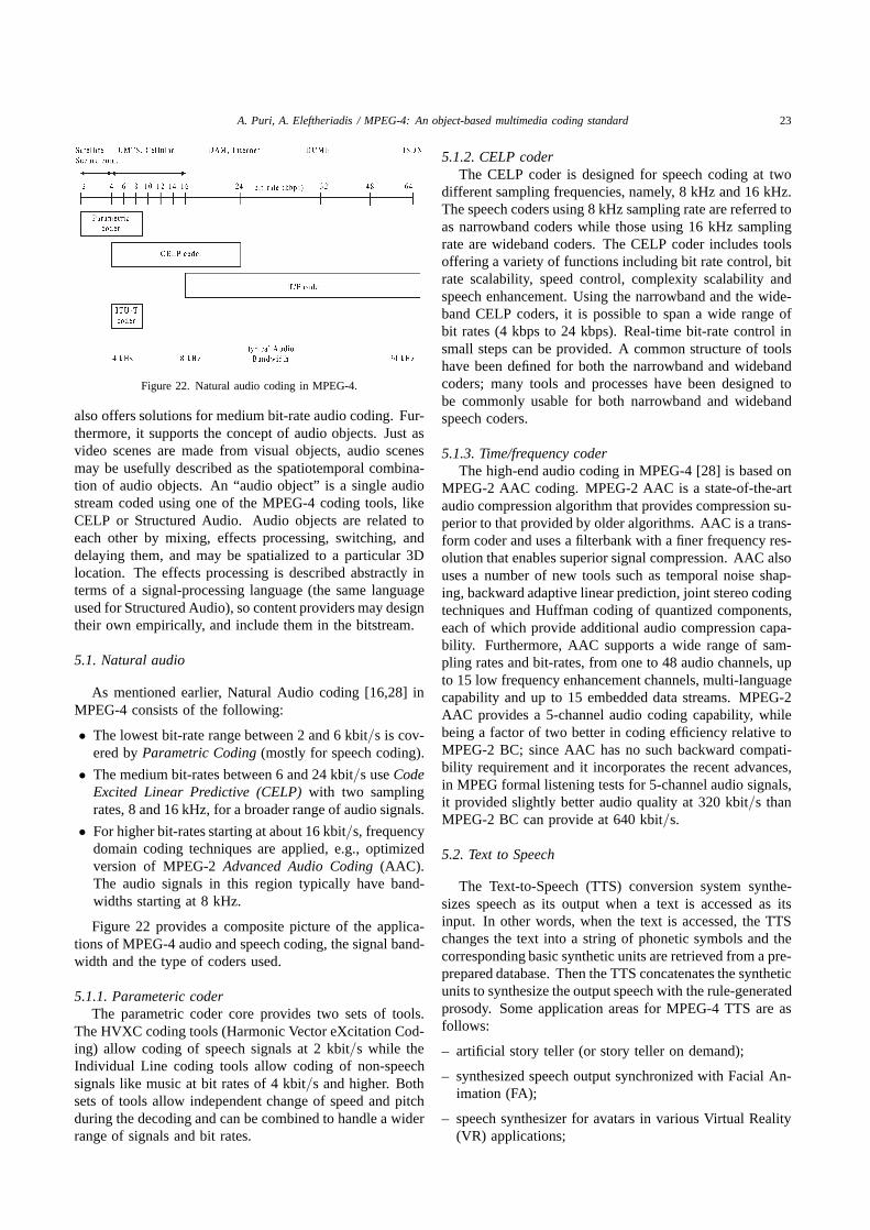
A. Puri, A. Eleftheriadis / MPEG-4: An object-based multimedia coding standard 23
Figure 22. Natural audio coding in MPEG-4.
also offers solutions for medium bit-rate audio coding. Fur-thermore, it supports the concept of audio objects. Just asvideo scenes are made from visual objects, audio scenesmay be usefully described as the spatiotemporal combina-tion of audio objects. An “audio object” is a single audiostream coded using one of the MPEG-4 coding tools, likeCELP or Structured Audio. Audio objects are related toeach other by mixing, effects processing, switching, anddelaying them, and may be spatialized to a particular 3Dlocation. The effects processing is described abstractly interms of a signal-processing language (the same languageused for Structured Audio), so content providers may designtheir own empirically, and include them in the bitstream.
5.1. Natural audio
As mentioned earlier, Natural Audio coding [16,28] inMPEG-4 consists of the following:
• The lowest bit-rate range between 2 and 6 kbit/s is cov-ered by Parametric Coding (mostly for speech coding).
• The medium bit-rates between 6 and 24 kbit/s use CodeExcited Linear Predictive (CELP) with two samplingrates, 8 and 16 kHz, for a broader range of audio signals.
• For higher bit-rates starting at about 16 kbit/s, frequencydomain coding techniques are applied, e.g., optimizedversion of MPEG-2 Advanced Audio Coding (AAC).The audio signals in this region typically have band-widths starting at 8 kHz.
Figure 22 provides a composite picture of the applica-tions of MPEG-4 audio and speech coding, the signal band-width and the type of coders used.
5.1.1. Parameteric coderThe parametric coder core provides two sets of tools.
The HVXC coding tools (Harmonic Vector eXcitation Cod-ing) allow coding of speech signals at 2 kbit/s while theIndividual Line coding tools allow coding of non-speechsignals like music at bit rates of 4 kbit/s and higher. Bothsets of tools allow independent change of speed and pitchduring the decoding and can be combined to handle a widerrange of signals and bit rates.
5.1.2. CELP coderThe CELP coder is designed for speech coding at two
different sampling frequencies, namely, 8 kHz and 16 kHz.The speech coders using 8 kHz sampling rate are referred toas narrowband coders while those using 16 kHz samplingrate are wideband coders. The CELP coder includes toolsoffering a variety of functions including bit rate control, bitrate scalability, speed control, complexity scalability andspeech enhancement. Using the narrowband and the wide-band CELP coders, it is possible to span a wide range ofbit rates (4 kbps to 24 kbps). Real-time bit-rate control insmall steps can be provided. A common structure of toolshave been defined for both the narrowband and widebandcoders; many tools and processes have been designed tobe commonly usable for both narrowband and widebandspeech coders.
5.1.3. Time/frequency coderThe high-end audio coding in MPEG-4 [28] is based on
MPEG-2 AAC coding. MPEG-2 AAC is a state-of-the-artaudio compression algorithm that provides compression su-perior to that provided by older algorithms. AAC is a trans-form coder and uses a filterbank with a finer frequency res-olution that enables superior signal compression. AAC alsouses a number of new tools such as temporal noise shap-ing, backward adaptive linear prediction, joint stereo codingtechniques and Huffman coding of quantized components,each of which provide additional audio compression capa-bility. Furthermore, AAC supports a wide range of sam-pling rates and bit-rates, from one to 48 audio channels, upto 15 low frequency enhancement channels, multi-languagecapability and up to 15 embedded data streams. MPEG-2AAC provides a 5-channel audio coding capability, whilebeing a factor of two better in coding efficiency relative toMPEG-2 BC; since AAC has no such backward compati-bility requirement and it incorporates the recent advances,in MPEG formal listening tests for 5-channel audio signals,it provided slightly better audio quality at 320 kbit/s thanMPEG-2 BC can provide at 640 kbit/s.
5.2. Text to Speech
The Text-to-Speech (TTS) conversion system synthe-sizes speech as its output when a text is accessed as itsinput. In other words, when the text is accessed, the TTSchanges the text into a string of phonetic symbols and thecorresponding basic synthetic units are retrieved from a pre-prepared database. Then the TTS concatenates the syntheticunits to synthesize the output speech with the rule-generatedprosody. Some application areas for MPEG-4 TTS are asfollows:
– artificial story teller (or story teller on demand);
– synthesized speech output synchronized with Facial An-imation (FA);
– speech synthesizer for avatars in various Virtual Reality(VR) applications;

24 A. Puri, A. Eleftheriadis / MPEG-4: An object-based multimedia coding standard
– voice news paper;
– dubbing tools for animated pictures;
– voice Internet;
– transportation timetables.
The MPEG-4 TTS [28] can not only synthesize speechaccording to the input speech with a rule-generated prosody,but also executes several other functions. They are as fol-lows:
(1) Speech synthesis with the original prosody from theoriginal speech.
(2) Synchronized speech synthesis with Facial Animation(FA) tools.
(3) Synchronized dubbing with moving pictures not byrecorded sound but by text and some lip shape infor-mation.
(4) Trick mode functions such as stop, resume, forward,backward without breaking the prosody even in the ap-plications with Facial Animation (FA)/ Motion Pictures(MP).
(5) Users can change the replaying speed, tone, volume,speaker’s sex, and age.
MPEG-4 TTS can be used for many languages in theworld since it adopts the concept of the language code suchas the country code for an international call. Presently, only25 countries, i.e., the current ISO members, have their owncode numbers, to identify that their own language has tobe synthesized, except the International Phonetic Alphabet(IPA) code assigned as 0. However, 8 bits have been as-signed for the language code to ensure that all countriescan be assigned language code when asked in the future.IPA could be used to transmit all languages.
For MPEG-4 TTS, only the interface bitstream profilesare the subject of standardization. Because there are alreadymany different types of TTS and each country has several ora few tens of different TTSs synthesizing its own language,it is impossible to standardize all the things related to TTS.However, it is believed that almost all TTSs can be modifiedto accept MPEG-4 TTS interface very quickly by a TTSexpert because of the rather simple structure of the MPEG-4TTS interface bitstream profiles.
5.3. Structured audio
Structured audio formats use ultra-low bit-rate algorith-mic sound models to code and transmit sound. MPEG-4standardizes an algorithmic sound language and several re-lated tools for the structured coding of audio objects. Usingthese tools, algorithms which represent the exact specifica-tion of a sound scene are created by the content designer,transmitted over a channel, and executed to produce soundat the terminal. Structured audio techniques in MPEG-4[28] allow the transmission of synthetic music and sound
effects at bit-rates from 0.01 to 10 kbit/s, and the concisedescription of parametric sound post-production for mix-ing multiple streams and adding effects processing to audioscenes
MPEG-4 does not standardize a synthesis method, but asignal-processing language for describing synthesis meth-ods. SAOL, pronounced “sail”, stands for “Structured Au-dio Orchestra Language” and is the signal-processing lan-guage enabling music-synthesis and effects post-productionin MPEG-4. It falls into the music-synthesis category of“Music V” languages; that is, its fundamental processingmodel is based on the interaction of oscillators running atvarious rates. However, SAOL has added many new ca-pabilities to the Music V language model which allow formore powerful and flexible synthesis description. Usingthis language, any current or future synthesis method maybe described by a content provider and included in the bit-stream. This language is entirely normative and standard-ized, so that every piece of synthetic music will sound ex-actly the same on every compliant MPEG-4 decoder, whichis an improvement over the great variety in MIDI-basedsynthesis systems.
The techniques required for automatically producing aStructured Audio bitstream from an arbitrary sound are be-yond today’s state of the art and are referred to as “auto-matic source separation” or “automatic transcription”. Inthe mean time, content authors will use special content cre-ation tools to directly create Structured Audio bitstreams.This is not a fundamental obstacle to the use of MPEG-4 Structured Audio, because these tools are very similarto the ones that content authors use already; all that isrequired is to make them capable of producing MPEG-4output bitstreams. There is no fixed complexity which isadequate for decoding every conceivable Structured Au-dio bitstream. Simple synthesis methods are very low-complexity, and complex synthesis methods require morecomputing power and memory. Since the description ofthe synthesis methods is under the control of the contentprovider, the content provider is responsible for understand-ing the complexity needs of the bitstreams. Past versions ofstructured audio systems with similar capability have beenoptimized to provide multitimbral, highly polyphonic mu-sic and post-production effects in real-time on a 150 MHzPentium computer or simple DSP chip.
6. MPEG-4 systems
The Systems [33] part of MPEG-4 perhaps representsthe most radical departure from previous MPEG specifica-tions. Indeed, the object-based nature of MPEG-4 necessi-tates a totally new approach on what the Systems layer isrequired to provide. Issues of synchronization and multi-plexing are, of course, still very essential. Note, however,that an MPEG-4 scene may be composed of several ob-jects, and hence synchronization between a large numberof streams is required. In addition, the spatio-temporal po-

A. Puri, A. Eleftheriadis / MPEG-4: An object-based multimedia coding standard 25
Figure 23. System decoder model.
sitioning of such objects forming a scene (or scene descrip-tion) is a key component. Finally, issues of interactivityare also quite new in MPEG as well.
6.1. System decoder model
A key problem in designing an audiovisual communi-cation system is ensuring that time is properly representedand reconstructed by the terminal. This serves two pur-poses: (1) it ensures that “events” occur at designated timesas indicated by the content creator, and (2) that the sendercan properly control the behavior of the receiver. The latteris essentially providing an open-loop flow control mecha-nism, a requirement for a specification that covers broad-cast channels (without an upstream, or feedback, channel).Assuming a finite set of buffer resources at the receiver,by proper clock recovery and timestamping of events thesource can always ensure that these resources are not ex-hausted.
Clock recovery is typically performed using clock ref-erences. The receiving system has a local system clockwhich is controlled by a PLL, driven by the differencesin received clock references and the local clock referencesat the time of their arrival. This way the receiver’s clockspeed is increased or decreased, matching that of the sender.In addition, coded units are associated with decoding timestamps, indicating the time instance in which a unit is re-moved from the receiving system’s decoding buffer. Thecombination of clock references and time stamps is suffi-cient for full control of the receiver.
In order to properly address specification issues withoutmaking unnecessary assumption about system implementa-tion, MPEG-4 Systems defines a System Decoder Model.This represents an idealized unit, in which operations can beunambiguously controlled and characterized. The MPEG-4System Decoder Model exposes resources available at thereceiving terminal, and defines how they can be controlledby the sender or content creator. The model is shown infigure 23. It is composed of a set of decoders (for the var-ious audio or visual object types), provided with two typesof buffers: decoding and composition.
The decoding buffers have the same functionality as inprevious MPEG specifications, and are controlled by clockreferences and decoding timestamps. In MPEG-2, each
program had its own clock. Proper synchronization wasensured by using the same clock for coding and transmit-ting the audio and video components. In MPEG-4, eachindividual object is assumed to have its own clock, or Ob-ject Time Base (OTB). Of course, several objects may sharethe same clock. In addition, coded units of individual ob-jects (Access Units – AUs, corresponding to an instanceof a video object or a set of audio samples) are associatedwith Decoding Timestamps (DTSs). Note that the decodingoperation at DTS is considered (in this ideal model) to beinstantaneous.
The composition buffers which are present at the de-coder outputs form a second set of buffers. Their use isrelated to object persistence. In some situations, a con-tent creator may want to reuse a particular object after ithas been presented. By exposing a composition buffer,the content creator can control the lifetime of data in thisbuffer for later use. This lifetime is controlled by an Expi-ration Timestamp (ETS). A decoded object is assumed toremain in this buffer until its ETS is reached, and can beused repeatedly until that time. This feature may be par-ticularly useful in low bandwidth wireless environments.MPEG-4 defines an additional timestamp, the CompositionTimestamp (CTS), which defines the time at which data istaken from the composition buffer for (instantaneous) com-position and presentation.
In order to coordinate the various objects, a single Sys-tem Time Base (STB) is assumed to be present at the receiv-ing system. All object time bases are subsequently mappedinto the system time base, so that a single notion of timeexists in the terminal. For clock recovery purposes, a singlestream must be designated as the master. The current spec-ification does not indicate the stream that has this role, buta plausible candidate is the one which contains the scenedescription. Note also that, in contrast with MPEG-2, theresolution of both the STB and the Object Clock References(OCRs) is not mandated by the specification. In fact, thesize of the OCR fields for individual Access Units is fullyconfigurable, as discussed later.
In other designs (e.g., IETF’s RTP), the assumption ofa globally known clock can be made (provided by othernetwork services such as NTP). There is work underway toprovide a unified methodology so that mapping of MPEG-4timing architecture can be seamlessly performed in such

26 A. Puri, A. Eleftheriadis / MPEG-4: An object-based multimedia coding standard
an environment as well. This is facilitated by the flexi-ble multiplexing methodology adopted in MPEG-4, and isdiscussed later.
6.2. Scene description
Scene description refers to the specification of the spatio-temporal positioning and behaviour of individual objects. Itis a totally new component in the MPEG specifications, andallows the easy creation of compelling audiovisual content.Scene description involves an architectural component, i.e.,the proper way to conceptually organize audiovisual infor-mation, and a syntactic component which is the mappingof such architecture into a bitstream. Note that the scenedescription is transmitted in a separate stream from the indi-vidual media objects. This allows one to change the scenedescription without operating on any of the constituent ob-jects themselves.
6.2.1. ArchitectureThe architecture of MPEG-4’s scene description is based
on the Virtual Reality Modeling Language (VRML) [2,20].Scenes are described as hierarchies of nodes forming atree. Leafs of the tree correspond to media objects (audioor visual, natural or synthetic), while intermediate nodesperform operations on their underlying nodes (grouping,transformation, etc.). Nodes also expose attributes throughwhich their behaviour can be controlled. This hierarchicaldesign is shown in figure 24.
There are however several key differences between thedomains that VRML and MPEG-4 address, which necessi-tate the adoption of slightly different approaches. MPEG-4is concerned with the description of highly dynamic scenes,where temporal evolution is more dominant than naviga-tion. VRML, on the other hand, allows the definition of astatic 3D world (static in the sense that all the objects inthat world are predefined and cannot be changed) in whicha user is allowed to navigate. As a result, scene descrip-tions in MPEG-4 actually have their own time base, andcan be updated at any time. Updates can take the formof a node’s replacement, elimination, insertion, or attributevalue modification. The presence of a time base and de-coding time stamps ensures the application of such updatesat the correct time instances.
In addition, MPEG-4 also needs to address pure 2D com-position of objects. The complexity and cost of 3D graphicsversus the possibility of developing low-cost or low-powersystems makes it desirable to partition the space of graph-ics capabilities. In figure 24 we see an example where both2D and 3D components coexist.
As a result of the close relationship of the MPEG-4 scenedescription with VRML, the types of scene description ca-pabilities provided by MPEG-4 are essentially those pro-vided by VRML nodes. It is currently examined if MPEG-4can be cast as an extension of VRML, with appropriatelydefined subsets as MPEG-4 specific profiles.
Figure 24. Scene description.
6.2.2. Binary format for scenesThe mapping of the scene description into a paramet-
ric form, suitable for low-overhead transmission has re-sulted in a scene description format called BInary Formatfor Scenes (BIFS). This representation format associateseach node with a node type. Nodes are then represented bytheir node type and a set of attribute value specifications.To avoid the specification of all attributes of a node, defaultvalues are used, and attributes are individually addressablewithin a node. This way one can, for example, only specifya non-default value for attribute X of a node of type Y.
Furthermore, nodes can optionally be reused. In thiscase, they are associated with an identifier which can appearin place of a node of the same type. In figure 24, forexample, the node “3D Obj 3” contains the child node “2DScene-1” which is used elsewhere in the scene as well. Asmentioned earlier, scene descriptions can be updated: nodescan be inserted, deleted, replaced, or their attributes can bemodified.
In addition to the VRML set of nodes, MPEG-4 definesits own set of nodes, particularly to handle media objectsincluding natural audio and video, still images, face ani-mation, basic MIDI, text-to-speech synthesizer, streamingtext, 2-D composition operators, layout control, etc.
6.2.3. InteractivityInteractivity in MPEG-4 can take two forms, client-
based and server-based. In the client-based case, user op-erations affect the local scene description. The VRMLmodel of events and routes is used within the BIFS format,thus providing direct support for a large variety of circum-stances. In addition, and noting that user events can betransformed to scene updates, one can also have a form ofinteractivity that does not necessitate normative support bythe specification: user events can form a secondary sourceof scene updates.
Server-based interaction requires the presence of an up-stream channel. The details of such a mode of interactivityare still under investigation, as they are slightly complicatedby the needs for network-independence.

A. Puri, A. Eleftheriadis / MPEG-4: An object-based multimedia coding standard 27
6.2.4. Adaptive audio-visual sessionAn additional, flexible mechanism for describing scenes
is also being developed, called Adaptive Audio-Visual Ses-sion (AAVS). This is based on the use of the Java languagefor constructing scenes, but not for composition, rendering,or decoding. By taking the programmable aspect of thesystem outside of the main data flow of decoders and therendering engine (which have to operate extremely fast),overall performance can be kept high. Note that the AAVSapproach is being designed as an extension of BIFS. Inthat sense, a BIFS scene can be a subset of an AAVS scene(but not vice versa). The AAVS work although started forMPEG-4 Version 1, will only be included in Version 2.
The benefits of the AAVS approach are in three majorcategories. First, because of its flexible nature, the scenedescription is capable of adapting to terminal capabilitieshence providing a form of graceful degradation. Secondly,when scene description operations can be expressed con-cisely in a flexible way (e.g., a spline trajectory), usinga flexible approach may result in increased compression.Finally, by allowing programmability, user interaction canextend beyond the modes defined in a parametric scene de-scription and become as rich as the content creator wishes.The use of programmability in an audiovisual terminal cer-tainly opens up a very broad spectrum of opportunities fora new generation multimedia applications.
6.3. Associating scene description with elementary streams
6.3.1. Object descriptorsIndividual object data as well as scene description infor-
mation is carried in separate Elementary Streams (ES). Asa result, BIFS media nodes need a mechanism to associatethemselves with the ESs that carry their data (coded naturalvideo object data etc.). A direct mechanism would neces-sitate the inclusion of transport-related information into thescene description. As we mentioned earlier, an importantrequirement in MPEG-4 is transport-independence. As aresult, an indirect way was adopted, using Object Descrip-tors (ODs).
Each media node is associated with an object identifier,which in turn uniquely identifies an OD. Within an OD,there is information on how many ESs are associated withthis particular object (may be more than one for scalablevideo/audio coding, or mutli-channel audio coding), andinformation describing each of those streams. The latterinformation includes the type of the stream, as well as howto locate it within the particular networking environmentused. This approach simplifies remultiplexing (e.g., goingthrough a wired-wireless interface), as there is only oneentity that may need to be modified.
6.3.2. Stream map tableThe object descriptor allows unique reference of an el-
ementary stream by an id; this id may be assigned by anapplication layer when the content is created. The transportchannel in which this stream is carried may only be assigned
at a later time by a transport entity; it is identified by achannel association tag associated to an elementary streamid by a stream map table. In interactive applications, the re-ceiving terminal may select the desired elementary streams,send a request and receive the stream map table in return.In broadcast and storage applications, the complete streammap table must be included in the applications signallingchannel.
6.4. Multiplexing
The key underlying concept in the design of the MPEG-4multiplexer is network independence. MPEG-4 contentmay be delivered across a wide variety of channels, fromvery low bit rate wireless, to high-speed ATM and broad-cast systems, to DVDs. A critical design question waswhat should be the tools included in the specification formandatory implementation. Clearly, the broad spectrum ofchannels could not allow a single solution to be used. Atthe same time, inclusion of a large number of different toolsand configuration would make implementations extremelycomplex and – through excessive fragmentation throughprofiles – make interoperability extremely hard to achievein practice. Consequently, the assumption was made thatMPEG-4 would not provide specific transport-layer featuresbut would instead make sure that it could be easily mappedto existing such layers. This is accomplished by allowingseveral components of the multiplexer to be configurable,thus allowing designers to achieve the desired trade-off be-tween functionality and efficiency. In addition, it is as-sumed that Quality of Service (QoS) guarantees may bemade available by the underlying transport service if sodesired.
The overall multiplexing architecture of MPEG-4 isshown in figure 25. At the top-most level, we have theAccess Unit Layer (AL) which provides the basic con-veyor of timing and framing information. It is at thislevel where timestamps and clock references are provided.The AL header, however, is very flexible: the presence ofOCR/DTS is optional, and their resolution (number of bits)is configurable. In addition, the header contains informationabout framing (start or end of a coded unit, random accessindicator), as well as sequence numbering. The latter is par-ticularly useful in error-prone wireless or broadcast envi-ronments, where preemptive retransmission of critical infor-mation (e.g., scene description) may be performed. Using asequence number a receiver that has already accurately re-ceived the information can ignore the duplicate. In order tobe able to “bootstrap” the demultiplexing process, the ALheader configuration information is carried in a channel thathas a predefined configuration.
Immediately below the AL we have the optional Flex-ible Multiplexer or “FlexMux” layer. This is a very sim-ple design, intended for systems that may not provide na-tive multiplexing services. An example is the data channelavailable in GSM cellular telephones. Its use, however, itentirely optional, and does not affect the operation of the

28 A. Puri, A. Eleftheriadis / MPEG-4: An object-based multimedia coding standard
Figure 25. MPEG-4 multiplexing architecture.
Figure 26. FlexMux modes.
rest of the system. As shown in the right side of figure 25there can be a “null” connection directly from the AccessUnit Layer to the lower layers. The FlexMux provides twomodes of operation, a “simple” and a “muxcode” mode, asshown in figure 26.
In the simple mode, data from a single object (or scenedescription) is present in the FlexMux payload (appropri-ately encapsulated as an AL PDU). In the MuxCode mode,data from multiple objects are placed in predefined posi-tions within the FlexMux payload. The ‘index’ field ofthe FlexMux header indicates which of the modes is used,depending on its value.
Finally, at the lowest level, we have the Transport Mul-tiplexing or “TransMux” layer which is not specified byMPEG-4. This can be any current or future transport layerfacility, including MPEG-2 Transport Stream, RTP, H.223,etc. For a mobile system, this layer must provide its ownprotection sublayer to ensure the desired QoS characteris-tics.
6.5. File format
The need for a file format for storage-based delivery(e.g., CD-ROM or DVD) of MPEG-4 content was recog-nized quite early during the MPEG-4 Systems work. In
addition to being a standardized format for interchange ofcoded MPEG-4 data, it was envisaged that the file formatwould support a host of functionalities including randomaccess to individual objects or portions of objects and ed-itability of coded objects. An early solution addressingthese capabilities was adopted and consisted of a simplelayer that substituted the TransMux layer and where ran-dom access information is provided in the form of direc-tories; this would potentially allow a user to rapidly moveback and forth in an MPEG-4 file having immediate ac-cess to Access Units of data. However, the anticipated roleof file format for MPEG-4 was revised to include stream-ing of coded MPEG-4 among others, and with a new setof requirements in place, an open call was made invitingproposals for file format.
A number of proposals, some backed by large segmentsof the multimedia industry, were received. Among theproposals received were Quicktime (Apple, IBM, Oracle,Netscape, SGI and Sun), Advanced Streaming Format (Mi-crosoft and Intel) and Integrated Intermedia Format (AT&Tand Columbia Univ.). A review of the proposals revealedthat for an MPEG-4 file format to be widely accepted in themultimedia community, it needed to focus on providing arich set of functionality while supporting existing multime-dia (legacy) content. One of the proposals (Quicktime) wasselected as the starting basis for MPEG-4 file format. Thisis expected to be embellished by incorporating key toolsfrom the other proposals to satisfy the unique requirementsof MPEG-4. It has also been decided that MPEG-4 will use‘.mp4’ as the extension for its file name. The file formatwill be included in MPEG-4 Version 2.
6.6. Syntactic description
Source coding, with its bit-oriented nature, directly con-flicts with the byte-oriented structure of modern micro-processors and makes the task of handling coded audio-

A. Puri, A. Eleftheriadis / MPEG-4: An object-based multimedia coding standard 29
visual information more difficult. A simple example is fastdecoding of variable length codes; every programmer thatwishes to use information using entropy coding must hand-code the tables so that optimized execution can be achieved.General-purpose programming languages such as C++ andJava do not provide native facilities for coping with suchdata. Even though other facilities already exist for repre-senting syntax (e.g., ASN.1 – ISO International Standards8824 and 8825), they cannot cope with the intricate com-plexities of source coding operations (variable length cod-ing etc.).
MPEG-4 Systems has adopted an object-based syntac-tic description language for the definition of its bitstreamsyntax (Flavor – Formal Language for Audio-Visual ObjectRepresentation [5,10–12]). It is designed as an extension ofC++ and Java in which the type system is extended to incor-porate bitstream representation semantics (hence forming asyntactic description language). This allows the descrip-tion, in a single place, of both the in-memory representationof data as well as their bitstream-level (compressed) repre-sentation as well. Also, Flavor is a declarative language,and does not include methods or functions. By buildingon languages widely used in multimedia application devel-opment, one can facilitate integration with an application’sstructure.
Figure 27 shows a simple example of a Flavor repre-sentation. Note the presence of bitstream representationinformation right after the type within the class declara-tion. The map declaration is the mechanism used in Flavorto introduce constant or variable length code tables (1-to-nmappings); in this case, binary codewords (denoted usingthe ‘0b’ construct) are mapped to values of type unsignedchar. Flavor also has a full complement of object-orientedfeatures pertaining to bitstream representation (e.g., “bit-stream polymorphism”) as well as flow control instructions(if, for, do-while, etc.). The latter are placed within thedeclaration part of a class, as they control the serializationof the class’ variables into a bitstream.
A translator has been developed that automatically gen-erates standard C++ and Java code from the Flavor sourcecode [5], so that direct access to, and generation of,compressed information by application developers can beachieved with essentially zero programming. This way, asignificant part of the work in developing a multimedia
Figure 27. A simple example of syntactic description.
application (including encoders, decoders, content creationand editing suites, indexing and search engines) is elimi-nated.
7. Profiles and levels
Although there are many tools in the MPEG-4 standard,not every MPEG-4 decoder will have to implement all ofthem. In fact, only a few classes of MPEG-4 decoders areexpected to exist with each class addressing clusters of ap-plications with similar requirements; this is accomplishedvia the concept of profiles. Similar to that in MPEG-2, aprofile is a defined sub-set of the entire bitstream syntax ofall the tools. A level is a defined set of constraints imposedon parameters in the bitstream. Conformance tests will becarried out against defined profiles at defined levels. Thepurpose of defining conformance points in the form of pro-files and levels is to facilitate bitstream interchange amongdifferent applications. Implementors of MPEG-4 are en-couraged to produce decoders and bitstreams which corre-spond to those defined conformance regions. The discretelydefined profiles and levels are the means of bitstream in-terchange between different applications of MPEG-4. Theconcept of profiles and levels of MPEG-2 Video [15,19]has been extended to MPEG-4 Video, Audio and Systemsspecifications.
Currently, MPEG is defining profiles for video objects,audio objects and systems for MPEG-4. In addition, itis likely that profiles may also be defined for composition.The work on profiles is ongoing and is thus likely to evolve;we now present the current structure of profiles envisagedand their key requirements [31,47,48]. Currently, three pro-files each are being considered for each of the three parts,video, audio and system objects; the requirements for theseprofiles are being established.
The profiles currently being considered for video are asfollows:
• Video simple object profile.
• Video random access object profile.
• Video main object profile.
In addition, recently, a profile known as ultra simple profileaddressing mobile and other applications has been proposedand is likely to be accepted.
Similarly, for audio, a number of profiles are being dis-cussed and are listed as follows:
• Audio speech object profile.
• Audio low delay object profile.
• Audio main object profile.
The three profiles being considered for systems are as fol-lows:
• Systems simple profile.
• Systems interactive profile.
• Systems main profile.

30 A. Puri, A. Eleftheriadis / MPEG-4: An object-based multimedia coding standard
Table 7Wireless network.
PCS IMT2000 (1) IMT2000 (2)
Data rate (total) 32 kbit/s 128 kbit/s 384 kbit/sError conditions Random Random Random
and burst and burst and burst
8. Verification tests
MPEG-4 is planning to hold verification tests to confirmthe performance of its various combination of tools thatwill form profiles. The first of the series of such tests [1]will take place in March 1998 and is aimed to verify errorresilience tools.
Version 1 of the MPEG-4 video codec is already im-plemented in software. It will be combined with simula-tions of the Universal Access Layer, a component of theMPEG-4 System Layer, and a TransMux. The particularTransMux to be implemented depends upon the applica-tion and corresponding network. For wireless applicationsthe TransMux will be ITU’s mobile multiplexing standard,H.223/Mobile. The overall encoding system to be sim-ulated for the demonstration of MPEG-4 over a wirelessnetwork consists of an application layer consisting of anMPEG-4 error resilient video encoder and simulated audiodata, an access unit layer consisting of adaptation layersfor audio and video data, H.223/Mobile layer consisting ofadaptation layers and a multiplexer. The multiplexed datais to be stored on PC hard drive and passes through phys-ical layer simulation to the decoding system that performsthe inverse operations such as H.223/Mobile demultiplexingand adaptation layers for audio and video, access unit layerconsisting of adaptation layer for audio and video data, andback to application layer which consists of simulated audiodata and MPEG-4 error resilient video decoder. The testconditions being considered are shown in table 7.
9. Beyond current MPEG-4 work
As mentioned earlier, the MPEG-4 work has been re-cently divided into two versions. The tools that were maturefor standardization have been incorporated in Version 1 andare complete while the work on the remaining tools con-tinues for Version 2. Version 2 tools are expected to eitherprovide new functionalities not supported by Version 1 orprovide some of the same functionality but a lot more ef-ficiently (or with higher quality or lower implementationcost). Generally, Version 2 is expected to maintain back-ward compatibility with Version 1.
Besides MPEG-4, the MPEG committee has recently ac-cepted a new work item on “Multimedia content descriptioninterface”, and is dubbed as MPEG-7, the next MPEG stan-dard. MPEG-7 has the primary goal of addressing the lim-ited capabilities and interoperability problems of proprietarysystems for content search and retrieval. Thus MPEG-7 willspecify [49] a standard set of descriptors that can be used to
identify various types of multimedia information. This de-scription shall be associated with the content itself, to allowfast and efficient searching for material of a user’s interest.AV material that has MPEG-7 data associated with it canthus be indexed and searched. However, MPEG-7 is notexpected to specify the actual search and retrieval engine.
10. Summary
In this paper we have introduced the MPEG-4 standardcurrently in progress. The necessary background informa-tion leading up to the MPEG-4 standard and the multiplefacets of this standard were discussed including the direc-tions for the future. The success of MPEG-4 will eventuallydepend on many factors such as market needs, competingstandards, software versus hardware paradigms, complexityversus functionality tradeoffs, timing, profiles, etc. Techni-cally, MPEG-4 appears to have a significant potential dueto the integration of natural and synthetic worlds, comput-ers and communication applications, and the functionalitiesand flexibilities it offers. Initially, perhaps only the verybasic functionalities will be useful. As the demand for so-phisticated multimedia grows, the advanced functionalitiesmay be useful. Up-to-date information on progress on var-ious topics in MPEG-4 can be found by visiting MPEGrelated websites [13,21,32,34,38].
References
[1] Ad Hoc Group on Error Resilience Core Experiments, Plan forMarch 1998 error resilience verification test, ISO/IEC JTC1/SC29/WG11 N1829, Stockholm (July 1997).
[2] A.L. Ames, D.R. Nadeau and J.L. Moreland, The VRML Sourcebook(Wiley, New York, 1996).
[3] AOE Group, MPEG-4 proposal package description (PPD) – Rev.3, ISO/IEC JTC1/SC29/WG11 N0998, Tokyo (July 1995).
[4] AOE Group, MPEG-4 testing and evaluation procedures document,ISO/IEC JTC1/SC29/WG11 N0999, Tokyo (July 1995).
[5] O. Avaro, P. Chou, A. Eleftheriadis, C. Herpel and C. Reader, TheMPEG-4 system and description languages, Signal Processing: Im-age Communication (Special issue on MPEG-4), to appear in 1997.
[6] L. Chiariglione, MPEG-4 call for proposals, ISO/IEC JTC1/SC29/WG11 N0997, Tokyo (July 1995).
[7] L. Chiariglione, Resolutions of 40th WG11 meeting, ISO/IECJTC1/SC29/WG11 N1716, Stockholm (July 1997).
[8] R. Cox, B. Haskell, Y. LeCun, B. Shahraray and L. Rabiner, On theapplications of multimedia processing to communications, AT&Tinternal technical memo; to appear in IEEE Transactions.
[9] T. Ebrahimi, Report of ad hoc group on definition of VMs for con-tent based video representation, ISO/IEC JTC1/SC29/WG11 MPEG96/0642, Munich (January 1996).
[10] A. Eleftheriadis, The MPEG-4 system description language: Frompractice to theory, in: Proceedings of 1997 IEEE International Con-ference on Circuits and Systems ISCAS ’97, Hong Kong (June 1997).
[11] A. Eleftheriadis, Flavor: A language for media representation, Pro-ceedings, ACM Multimedia ’97 Conference (November 1997) (toappear).
[12] Y. Fang and A. Eleftheriadis, A syntactic framework for bitstream-level representation of audio-visual objects, in: Proceedings of 3rdIEEE International Conference on Image Processing ICIP ’96, Lau-sanne, Switzerland (September 1996).

A. Puri, A. Eleftheriadis / MPEG-4: An object-based multimedia coding standard 31
[13] Flavor Web Site: http://www.ee.columbia.edu/flavor.[14] J. Gosling, B. Joy and G. Steele, The Java Language Specification
(Addison-Wesley, Reading, MA, 1996).[15] B.G. Haskell, A. Puri and A.N. Netravali, Digital Video: An Intro-
duction to MPEG-2 (Chapman and Hall, London, 1997).[16] B.G. Haskell, A. Puri and J. Osterman, Happenings in ISO MPEG:
An introduction to MPEG-4, invited presentation at Data Compres-sion Conference, Snow Bird (March 1997).
[17] IEEE Transactions on Circuits and Systems for Video Technology(Special issue on MPEG-4) 7(1) (February 1997).
[18] ISO/IEC 11172 International Standard (MPEG-1), Information tech-nology – Coding of moving pictures and associated audio for digitalstorage media at up to about 1,5 Mbit/s (1993).
[19] ISO/IEC 13818 International Standard (MPEG-2), Information tech-nology – Generic coding of moving pictures and associated audio(also ITU-T Rec. H.262) (1995).
[20] ISO/IEC 14472 draft international standard: Virtual reality modelinglanguage (1997).
[21] ISO/IEC JTC1/SC29/WG11 (MPEG) Web Site: http://drogo.cselt.it/mpeg.
[22] ITU-T Recommendation H.261, Video codec for audio-visual ser-vices at p×64 kbit/s (1990).
[23] ITU-T, Draft ITU-T Recommendation H.263: Video coding for lowbit-rate communication (December 1995).
[24] ITU-T Recommendation H.223: Multiplexing protocol for low bit-rate multimedia communication (1995).
[25] ITU-T Recommendation H.223 Annex A: Multiplexing protocol forlow bit-rate mobile multimedia communication (1996).
[26] ITU-T H.263+ Video Group, Draft 12 of ITU-T RecommendationH.263+ (May 1997).
[27] D. Lindbergh, The H.324 multimedia communication standard, IEEECommunications Magazine 34(12) (December 1996) 46–51.
[28] MPEG-4 Audio Group, MPEG-4 audio working draft version 4.0,ISO/IEC JTC1/SC29/WG11 N1745, Stockholm (July 1997).
[29] MPEG-4 Integration Group, MPEG-4 SNHC call for proposals,ISO/IEC JTC1/SC29/WG11 N1195, Florence (March 1996).
[30] MPEG-4 Integration Group, MPEG-4 SNHC proposal packagedescription, ISO/IEC JTC1/SC29/WG11 N1199, Florence (March1996).
[31] MPEG-4 Requirements Ad Hoc Group, Draft of MPEG-4 require-ments, ISO/IEC JTC1/SC29/WG11 N1238, Florence (March 1996).
[32] MPEG-4 SNHC Web Site: http://www.es.com/mpeg4-snhc.[33] MPEG-4 Systems Group, MPEG-4 systems working draft version
5.0, ISO/IEC JTC1/SC29/WG11 N1825, Stockholm (July 1997).[34] MPEG-4 Systems Web Site: http://garuda.imag.fr/MPEG4.[35] MPEG-4 Video and SNHC Groups, MPEG-4 visual working draft
version 4.0, ISO/IEC JTC1/SC29/WG11 N1797, Stockholm (July1997).
[36] MPEG-4 Video Group, MPEG-4 video verification model version2.0, ISO/IEC JTC1/SC29/WG11 N1260, Florence (March 1996).
[37] MPEG-4 Video Group, MPEG-4 video verification model version7.0, ISO/IEC JTC1/SC29/WG11 N1642, Bristol (April 1997).
[38] MPEG-4 Video Web Site: http://wwwam.hhi.de/mpeg-video.[39] H. Peterson, Report of the ad hoc group on MPEG-4 video testing
logistics, ISO/IEC JTC1/SC29/WG11 Doc. MPEG95/0532, (Novem-ber 1995).
[40] A. Puri, Status and direction of the MPEG-4 standard, in: Inter-national Symposium on Multimedia and Video Coding, New York(October 1995); also published in a book by Plenum Press.
[41] A. Puri, Report of ad hoc group on coordination of future coreexperiments in MPEG-4 video, ISO/IEC JTC1/SC29/WG11 MPEG96/0669, Munich (January 1996).
[42] A. Puri, MPEG-4: A flexible and extensible multimedia coding stan-dard in progress, invited paper in IEEE Multimedia book (1996).
[43] A. Puri, A.R. Reibman, R.L. Schmidt and B.G. Haskell, Robustnessconsiderations in ISO MPEG-4 and ITU-T mobile video standards,in: Proceedings MoMuC-3, Princeton (September 1996) (PlenumPress, 1997).
[44] A. Puri, R.L. Schmidt and B.G. Haskell, Improvements in DCT-based video coding, in: Proc. SPIE Visual Communications andImage Processing, San Jose (February 1997).
[45] Requirements Group, MPEG-4 applications document, ISO/IECJTC1/SC29/WG11 N1729, Stockholm (July 1997).
[46] Requirements Group, MPEG-4 overview, ISO/IEC JTC1/SC29/WG11 N1730 (July 1997).
[47] Requirements Group, MPEG-4 profile requirements version 4,ISO/IEC JTC1/SC29/WG11 N1728, Stockholm (July 1997).
[48] Requirements Group, MPEG-4 requirements version 4, ISO/IECJTC1/SC29/WG11 N1727, Stockholm (July 1997).
[49] Requirements Group, MPEG-7 context and objectives version 4,ISO/IEC JTC1/SC29/WG11 N1733, Stockholm (July 1997).
[50] Signal Processing: Image Communication (Special issue on MPEG-4, Part 1: Invited papers) 10(1–3) (May 1997).
[51] Signal Processing: Image Communication (Special issue on MPEG-4, Part 2: Submitted papers) 10(4) (July 1997).
[52] P.J.L. van Beek, A.M. Tekalp and A. Puri, 2D mesh geometry andmotion compression for efficient object-based video compression,IEEE Int. Conf. on Image Processing (October 1997), to appear.
Atul Puri received his B.S. in electrical engineer-ing from India in 1980, his M.S. in electrical engi-neering from City College of New York in 1982,and his Ph.D., also in electrical engineering, fromthe City University of New York in 1988. Whileworking on his dissertation, he was a consultantin Visual Communications Research Departmentof Bell Labs and gained experience in develop-ing algorithms, software and hardware for videocommuniucations. In 1988 he joined the same de-
partment at Bell Labs as a Member of Technical Staff. Since 1996, Dr.Puri has been a Principal Member of Technical Staff in the Image Process-ing Research Department of AT&T Labs and is presently located at RedBank, NJ. Dr. Puri has represented AT&T at the Moving Pictures ExpertGroup standards of the International Standards Organization for the past9 years and has actively contributed towards development of the MPEG-1,the MPEG-2 and the MPEG-4 audio-visual coding standards. Currentlyhe is participating in video and systems parts of the MPEG-4 standardand is also a technical editor of the standard. He has been involved inresearch in video coding algorithms for a number of diverse applicationssuch as videoconferencing, video on digital storage media, HDTV, 3D-TV and wireless video. His current interests are in the area of multimediaservices and systems for Web/Internet. Dr. Puri holds over 14 patents andhas applied for another 8 patents. He has also published over 30 techni-cal papers in conferences and journals, including several invited papers.He is the co-author of a book entitled “Digital Video: An Introduction toMPEG-2”. He is currently coediting another book. He has been the recip-ient of exceptional contribution and individual performance merit awardsof AT&T. Furthermore, he has also received awards from the Communi-cation Services business unit, and the AT&T Technical Journal. He hastaught graduate courses on Digital Image and Video Coding at ColumbiaUniversity. He is also an active member of IEEE, its Communications,and Signal Processing societies.E-mail: [email protected]
Alexandros Eleftheriadis was born in Athens,Greece, in 1967. He received the Diploma in elec-trical engineering and computer science from theNational Technical University of Athens, Greece,in 1990, and the M.S., M.Ph. and Ph.D. degreesin electrical engineering from Columbia Univer-sity, New York, in 1992, 1994 and 1995, respec-tively. Since 1995 he has been an Assistant Pro-fessor in the Department of Electrical Engineeringat Columbia University, where he is leading a re-

32 A. Puri, A. Eleftheriadis / MPEG-4: An object-based multimedia coding standard
search team working in the areas of visual information representation andcompression, video communication systems (including video-on-demandand Internet video), distributed multimedia systems, and the fundamentalsof compression. During the summers of 1993 and 1994, he was withAT&T Bell Laboratories, Murray Hill, NJ, developing low bit rate model-assisted video coding techniques for videoconferencing applications. From1990 until 1995, he was a Graduate Research Assistant in the Depart-
ment of Electrical Engineering at Columbia University. Dr. Eleftheri-adis is a member of the ANSI NCITS L3.1 Committee and the ISO/IECJTC1/SC29/WG11 (MPEG) group that develop national and internationalstandards for audio-visual content representation and distribution. He is amember of IEEE, ACM, and the Technical Chamber of Greece.E-mail: [email protected]