Embed Size (px)
Citation preview

ENGLISH
MO Series MonitorsUser Manual
simrad-yachting.com


| 3 MO Series User Manual
PrefaceAs Navico is continuously improving this product, we retain the right to make changes to the product at any time which may not be reflected in this version of the manual. Please contact your nearest distributor if you require any further assistance.
It is the owner’s sole responsibility to install and use the instrument and transducers in a manner that will not cause accidents, personal injury or property damage. The user of this product is solely responsible for observing safe boating practices.
NAVICO HOLDING AS AND ITS SUBSIDIARIES, BRANCHES AND AFFILIATES DISCLAIM ALL
LIABILITY FOR ANY USE OF THIS PRODUCT IN A WAY THAT MAY CAUSE ACCIDENTS, DAMAGE
OR THAT MAY VIOLATE THE LAW.
Governing Language: This statement, any instruction manuals, user guides and other information relating to the product (Documentation) may be translated to, or has been translated from, another language (Translation). In the event of any conflict between any Translation of the Documentation, the English language version of the Documentation will be the official version of the Documentation.
This manual represents the product as at the time of printing. Navico Holding AS and its subsidiaries, branches and affiliates reserve the right to make changes to specifications without notice.
CopyrightCopyright © 2020 Navico Holding AS.
WarrantyThe warranty card is supplied as a separate document.
In case of any queries, refer to the brand website of your display or system:
www.simrad-yachting.com
Compliance StatementsThe Simrad MO series monitors:
• Complies with CE under EMC directive 2014/30/EU.
• Complies with the requirements of level 2 devices of the Radiocommunications (Electromagnetic Compatibility) standard 2017.
The relevant Declaration of Conformity is available in the following website under model documentation section: www.simrad-yachting.com
WarningThe user is cautioned that any changes or modifications not expressly approved by the party responsible for compliance could void the user’s authority to operate the equipment.
Trademarks• NMEA 2000 is a registered trademark of the National Marine Electronics Association.
• Navionics is a registered trademark of Navionics SpA.
• Simrad is a trademark of Kongsberg Maritime AS Company registered in the US and other countries and is being used under license.
• B&G, StructureScan, Navico, SonicHub, SimNet, Skimmer, InsightHD, Broadband Radar and Broadband Sonar are trademarks of Navico, registered in the US and other countries.

4 | MO Series User Manual
About this manualThis manual is a reference guide for installing and operating the Simrad MO Series monitors.
The manual does not cover basic background information about how equipment such as radars, echosounders and AIS work.
Important text that requires special attention from the reader is emphasized as follows:
¼ Note: Used to draw the reader’s attention to a comment or some important information.
! Warning: Used when it is necessary to warn personnel that they should proceed carefully to prevent risk of injury and/or damage to equipment/personnel.

| 5 Contents | MO Series User Manual
Contents
6 Introduction6 Items included
7 Display installation7 Cutout template7 Fixing options8 Flush-mounting the display11 VESA mounting the display
12 Connecting the display12 Rear connections12 Cable retention13 Connecting power14 Connecting touch control14 Serial connection14 USB connection15 Connecting NMEA 200015 Connecting HDMI cable16 Typical installation
17 Operating the display17 First time operation17 Shortcut functions17 OSD menu19 Updating the firmware19 Checking current firmware version19 Installing an Update
20 Dimensional drawings
21 Troubleshooting tips
22 Cleaning and maintenance22 Display removal22 Replacing the gasket23 Replacing the filters23 Other maintenance
24 General specifications
25 Accessories

6 | Introduction | MO Series User Manual
IntroductionThe Simrad MO Series monitors offer a low profile, high brightness solution for displaying video from a variety of sources. The range includes six models; the 16”, 19”, and 24” Touch series, and the 16”, 19” , and 24” Pilot series. The Touch models are suited to both indoor and outdoor (direct sunlight) use, whereas the Pilot series are suited to enclosed helm installations. The Pilot series do not utilize a touchscreen, therefore when connected to a Marine Processor, require an external controller such as the OP40. All monitors in the range accept video via HDMI, DVI-I and composite inputs.
Items included12
18
12
13
1716
10
19 20
3
4
5
9
8
6
7
11
15
14
21
1 Monitor
2 Dash mount brackets (x2)
3 Washer, M4, 12 mm, SS (x4)
4 Pozi pan head machine screw, M4 x 12 mm, SS (x4)
5 Plastic spacer (x4)
6 Wing nut M5 (x4)
7 Wing head machine screw (x4)
8 Plastic stopper - dash mount (x4)
9 Pozi pan head self-tapping screw 4G x 1/2” (x12)
10 Cable retention bracket with screws 4G x 1/2” (x4)
11 Cable ties (x4)
12 Connector block (serial data)
13 Micro-C tee piece
14 Micro-C cable, 2 m (6ft)
15 Power cable with connector
16 Bezel trim, black (x2)
17 Bezel trim, silver (x2)
18 Operator manual
19 Cutout template
20 Warranty card
21 Drill and screw guide tool
1

| 7 Display installation | MO Series User Manual
Display installationIt is recommended that the unit be powered and connected to a video source to assist in selecting a suitable mounting location, prior to irreversible modification of the vessel’s helm station. When planning the display location, the following points should be considered to ensure safe, comfortable and reliable operation:
• Convenience - the mounting location should be easily accessible to allow operation of the controls and should enable easy viewing of the display.
• Viewing angle - the viewing angle influence the viewability of the monitor. The recommended viewing angles relative to perpendicular are shown in the illustrations below.
MO16
MO19
Horizontal viewing angles
A: Optimum viewing angle
B: Good viewing angle
C: Poor viewing angle or obstructed view
MO24
Vertical viewing angles
• Access - there must be sufficient space behind the display to allow cable connections to the rear connectors, avoiding tight bends in the cable. Also ensure there is sufficient access for tightening wing nuts/screws on the mounting brackets, where used.
• Interference - the selected location should be far enough away from devices that may cause interference, such as motors, generators and radio transmitters/receivers.
• Magnetic compass - mount the display at least 1 metre (3 ft.) away from a magnetic compass.
• Environment - to prevent overheating, do not restrict airflow at the rear of the display unit; ensure that there is adequate ventilation, particularly if the display unit is pod-mounted. If the space behind the display is air conditioned or cooled by a fan, it will help in keeping the unit’s temperature down when mounted in direct sunlight. The display should be protected from physical damage and excessive vibration. Although the display unit is waterproof from the front when installed correctly, it is good practice to mount it in a protected area away from prolonged and direct exposure to rain and salt spray.
! Warning: Damage incurred to monitor through failure to provide adequate ventilation could invalidate your warranty. Do not recess device in to an enclosure shared with a heat source. e.g. engine compartment.
Cutout templateUse the supplied scale template to help mark up the cutout area.
¼ Note: Always check the template dimensions against the physical monitor to ensure dimensions are correct, prior to making the cutout.
Fixing optionsThe MO series monitors can be dash or bracket mounted (using optional VESA adaptor).
When dash mounting, unit should be fitted using the rear mounted dash mount brackets, and bezel screws from the front. Exclusion of the dash mount bracket will greatly increase
2A
C
C C
C
B
A A
40°
70°
20°80° 80°
A
C
C
A
80°
80°

8 | Display installation | MO Series User Manual
strain on bezel screws and adjacent bezel plastics, and is not recommended.
Flush-mounting the display ¼ Note: The following guidelines and warnings apply:
Hard materials e.g. GRP, Acrylic, hardwoods 2.3 - 2.5 mm (3/32")
Important drill bit size selection information
Front mount screw recommendations
Soft materials e.g. Plywood 1.9 - 2.3 mm (5/64")
Max 5.5 mm(0.22”)
1. Fit the supplied M4 machine screws, washers, and plastic spacers to each of the four threaded fittings on the back case of screen. Hand tighten only.
REMOVE SHADED AREA
*988-10455-001*NOTE:
DO NOT SCALE
PRINT 1:1
IMPORTANT. Do not use this template if it has been rescaled
by copying or prin ng. If this is not the original, or is a print
from a �le, please check the dimension lines below are to
scale before use.IMPORTANT. Ne pas u liser ce gabarit s’il a été photocopié ou
imprimé en format réduit ou agrandi. Si ce gabarit n’est ni un
original ni une version imprimée d’un � chier PDF, veuillez
véri� er qu’il est à l’échelle avant de l’u liser.
IMPORTANTE. no usar la plan lla si hay peligro que la escala
original exacta se ha alterado por copias o procesos de
impresión imprecisos. Si esto no es el original, o un PDF, veri�
car que las líneas abajo están a la escala antes de usar.
WICHTIG. Diesen Vordruck nicht verwenden, wenn er durch
Kopieren oder Drucken im Maßstab verändert wurde. Sollte
es nicht das Original oder ein PDF-Ausdruck sein, müssen
untenstehende Zeilen vor erwendung an den rich gen
Maßstab angepasst werden.
BELANGRIJK. Gebruik deze mal niet indien de schaal is veran-
derd doordat het is gecopieerd of gedrukt. Indien deze mal
niet het origineel of een print van PDF is, controleer dan of de
onderstaande lijnen de juiste schaal zijn voordat u ze gebrui-
kt.
IMPORTANTE. Não u lize este gabarito se a escala do mesmo
ver sido alterada por cópia ou impressão. Se não for o
original ou uma cópia impressa de um arquivo PDF, veri� que
as linhas abaixo, para acertar a escala antes da u lização.
VIKTIGT. Använd inte denna mall om den skalats om genom
utskri eller kopiering. Om dea inte är originalet eller en
utskri från en PDF, kontrollera a linjerna nedan stämmer
med skalan innan det används.
IMPORTANTE. Non u lizzare questo modello se è stato
ridimensionato copiandolo o stampandolo. Se questo non è
l’originale o la stampa di un � le PDF, veri� care se le linee che
seguono devono essere dimensionate prima di essere u lizza-
te.
TÄRKEÄÄ. Älä käytä tätä kaaviota, jos sen mi akaava on
muuunut kopio-idessa tai tulostaessa. Jos tämä ei ole alku-
peräinen tai PDF tuloste tarkista rajat mi akaavasta alla
ennen käy öä.注意:请尽量不要使用本安装挖孔尺寸模版图的复印件。
如果使用复印件,则在使用之前请确认其比例一定要与原
件大小必须一致。
중요
: 복사
나 출
력으
로 크
기가
조정
된 경
우 이
템플
릿을
사용
하지
마십
시오
. 원본
이 아
니거
나 인
쇄물
이면
,
사용
하기
전 아
래 치
수선
의 눈
금을
확인
해 주
십시
오.
注:
この
テン
プレー
トは
印刷
やコ
ピーに
よっ
て縮
尺が変
わっ
てい
るこ
とが
あり
ます
ので
使用
しな
いで
下さ
い。
テ
ンプ
レート
がオ
リジ
ナル
のも
ので
ない
場合
には
、下
の寸
法線
を使
って
縮尺
を確
認し
てく
ださ
い。
ВНИМАНИЕ: Не используйте эту инструкцию, ес
ли она была изменена в размерах при копирова
нии или распечатке. Если вы используете не ор
игинал, а распечатку из файла, убедитесь в соо
тветствии размеров линейки в нижней части и
нструкции с действительными размерами.
Check dimensions before cutting
12"
300 mm
L C
LC 192.5 mm (7.58")
186.0 mm (7.32")
192.5 mm (7.58")
186.0 mm (7.32")
200.0 mm (7.87")
117.
5 m
m (
4.63
")
111.
0 m
m (
4.37
")
130.
0 m
m (
5.12
")13
0.0
mm
(5.
12")
117.
5 m
m (
4.63
")
111.
0 m
m (
4.37
")
200.0 mm (7.87")
385.0 mm (15.16")
372.0 mm (14.65")
400.0 mm (15.75")
235.
0 m
m (
9.25
")22
2.0
mm
(8.
74")
260.
0 m
m (
10.2
4")
MO16Marine Monitor
X4
1
3
x4
x2
4
CLICK
5
6
7
2
2. Tape appropriate mounting template in place on dash, and ensure cutout lines are level relative to a reference point on dash.
3. Drill top and bottom mounting screw holes using an appropriate drill bit for the surface material:
• Soft materials e.g. Plywood - 1.9 - 2.3 mm (5/64”)
• Hard materials e.g. GRP, Acrylic, hardwoods - 2.3 - 2.5 mm (3/32”)
4. Drill cutout corners with a small pilot drill bit followed with 13 mm drill bit. Complete cutout with jigsaw or similar tool.

| 9 Display installation | MO Series User Manual
5. Place the display in the dash hole.6. Place the guide tool on the glass of the display.7. Slide the tool across so the drill bit hole guide lines up with the center of a screw
location hole on the case of the display.8. Drill the pilot hole.
¼ Note: Before drilling the rest of the pilot holes it is recommended to secure the display with at least one screw to allow for movement in the dash cutout.
9. Insert one of the supplied screws in to the screw guide and tighten using a hand screw driver.
10. Repeat for the rest of the mounting screws.
11. Wind wing nut on to wing screw, then wind the wing screw assembly in to bracket till approximately 5 mm of threaded rod protrudes through other side of bracket.
12. Fit stopper foot on to end of wing screw.
13. Complete for both threaded holes on each bracket.
14. Fit brackets to rear of display, aligning ‘key holes’ on bracket with screws on back of display case.

10 | Display installation | MO Series User Manual
CLICK
15. With bracket making contact with back of monitor, slide bracket down till it engages with a click and is held in place.
16. Wind in the wing screw, until stoppers make firm contact with rear of dashboard material.
17. Check front of unit, ensuring that unit’s bezel is making even contact with the dash surface.
18. Hand tighten wing nuts against the back of the mounting brackets to lock the wing screw in place. Hold wing screw stationary if it turns while adjusting the wing nut.
19. When fitting bezels, ensure hook tabs on back of each bezel recess into opposing slots on screen frame. Once flush with front surface of screen, slide top bezel to the left, and bottom bezel to the right to lock in to place.

| 11 Display installation | MO Series User Manual
VESA mounting the displayA VESA bracket adaptor is available as an optional part for all display sizes, allowing a variety of wall and free standing bracket mounting options. The fasteners for attachment to the display are included with the bracket.
Monitors mounted using a VESA bracket have IPX2 rating, and should be mounted in an area sheltered from rain and sea spray.
¼ Note: Bracket and monitor shown apply to MO16/19 models. MO24 is fastened with six machine screws.
¼ Note: The monitor should not be tilted forward by more than 15 degrees, as this compromises the IPX2 rating. In fully enclosed helm stations, this limitation may be disregarded.
¼ Note: The bracket mounting points on the monitor are only intended to carry the weight of the monitor - do not install the monitor in such a place where it may be used as a hand hold, or have additional equipment attached to it.
12 | Connecting the display | MO Series User Manual
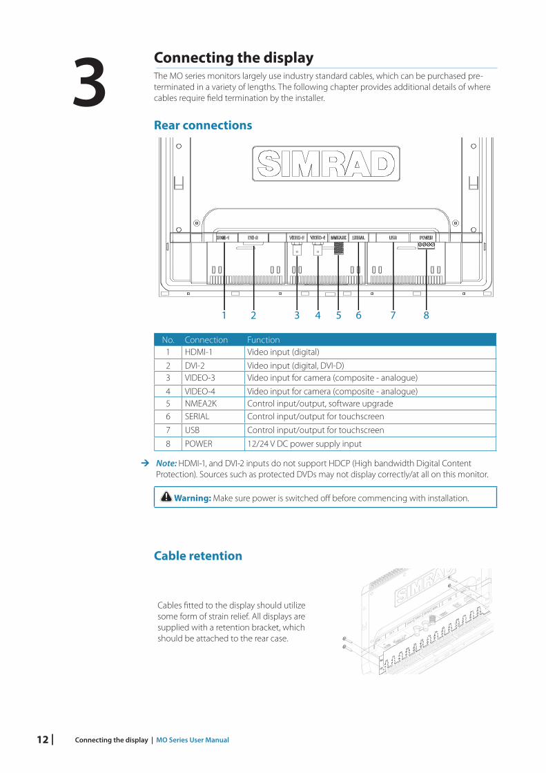
Connecting the displayThe MO series monitors largely use industry standard cables, which can be purchased pre-terminated in a variety of lengths. The following chapter provides additional details of where cables require field termination by the installer.
Rear connections
1 2 3 4 5 6 7 8
No. Connection Function1 HDMI-1 Video input (digital)
2 DVI-2 Video input (digital, DVI-D)3 VIDEO-3 Video input for camera (composite - analogue)
4 VIDEO-4 Video input for camera (composite - analogue)5 NMEA2K Control input/output, software upgrade6 SERIAL Control input/output for touchscreen
7 USB Control input/output for touchscreen
8 POWER 12/24 V DC power supply input
¼ Note: HDMI-1, and DVI-2 inputs do not support HDCP (High bandwidth Digital Content Protection). Sources such as protected DVDs may not display correctly/at all on this monitor.
! Warning: Make sure power is switched off before commencing with installation.
Cable retention
Cables fitted to the display should utilize some form of strain relief. All displays are supplied with a retention bracket, which should be attached to the rear case.
3

| 13 Connecting the display | MO Series User Manual
With the cable and plug fitted in place, secure the cable to the retention bracket using a cable tie. Do not secure in such a way that it applies strain to the cable, or causes the plug or socket to be bent out of alignment.
Connecting power
3 421
1 2
3 4 5
6 + -
No. Color Function
1 Yellow Power control
2 Green Chassis ground
3 Red Positive DC supply (12 V or 24 V system)
4 Black Negative DC supply (12 V or 24 V system)
5 Fuse - see table at end of section
6 DC supply
¼ Note: This display is not intended for use on vessels fitted with a positive ground electrical system. The power input cable screen drain wire should be connected to a negative ground.
¼ Note: Chassis ground will typically not be required. In certain problematic installations it may help stabilize touch screen sensitivity, ie. prevent ‘false’ touches, or non-registered touches.
Recommended fuse rating
Model MO16-T MO19-T MO24-T MO16-P MO19-P MO24-P
Fuse 3 amp 4 amp 7.5 amp 2 amp 2 amp 4 amp

14 | Connecting the display | MO Series User Manual
Connecting touch controlThe touch screen models of the MO series monitors can provide touch control to NSO Marine Processors, as well as Windows PCs. Connection can be made via serial data to a NSO Marine Processor, or USB for PC systems.
Serial connectionThe MO series monitors should always be connected to NSO Marine Processor via serial. Make all connections with the power turned off.
Pin Purpose1 RS422 Listener - (Rx-)2 RS422 Listener + (Rx+)3 RS422 Talker - (Tx-)4 RS422 Talker + (Tx+)
3 421
¼ Note: Serial connection will support very long cable runs provided a good quality cable designed for serial data is used.
Example connectionThe illustration shows an NSO evo3 MPU connection, wire colors may vary. Refer to the documentation for your NSO Marine Processor for wiring details. The NMEA 0183 wires (A) are not to be used for touch operation.
A
Tx -Tx +Rx -Rx +
Rx -Rx +Tx -Tx +
NMEA2K SERIAL
USB connectionConnection using USB is straightforward, as regular off-the-shelf cables may be used, which are available in various lengths (generally up to 5 m). The monitor end must be fitted with a USB type B male plug. The opposite end should suit the device being controlled, which typically will use the common USB type A male plug.

| 15 Connecting the display | MO Series User Manual
¼ Note: Where USB is used, cable length should not exceed 5 m when using regular cables. Lengths over 5 m may be possible with the use of a USB cable fitted with active boosting.
¼ Note: Do not connect both serial and USB to the same video source.
¼ Note: Ensure any third party video source connected to the MO has an isolated USB connection to avoid potential damage due to incorrect installation, or failure elsewhere in the system.
¼ Note: The preferred method of connection is via serial cable, only serial touch can be configured to work for a specific video input. USB touch is output regardless of video input selection, which can lead to false touches when viewing a different video source.
Connecting NMEA 2000When connected to a compatible processor, such as the NSO Marine Processor, the display should also be connected to the NMEA 2000 network. This enables the monitor’s home key to bring up the home screen. NMEA 2000 is also used for applying software updates from the processor to the display.
¼ Note: If the monitor is connected to the NMEA 2000 network and the monitor has its key beeps turned on, it will sound for any network alarm when the focus is on that screen.
Connecting HDMI cableAll hardware devices must be turned off prior to connecting or disconnecting the HDMI cable.

16 | Connecting the display | MO Series User Manual
Typical installation
4
2 8 9
1
7
6
3
5
10
11
No. Description
1 MO16-T/P, MO19-T/P, or MO24-T/P monitor
2 HDMI cable (non HDCP sources only)
3 DVI-D cable (eg. PC, non HDCP sources only)
4 Composite video cable (eg. video camera)
5 NSO Marine Processor
6 FLIR® IR camera
7 NMEA 2000 (Micro-C network bus)
8 Serial cable - communicates touch control to the NSO Marine Processor
9 Power cable - monitor
10 NMEA 2000 drop cable (Micro-C network drop cable) - allows software updating of monitor via a NSO Marine Processor
11 Power cable - NSO Marine Processor
¼ Note: Peripheral devices in diagram do not necessarily show all required connections where not directly related to MO series monitor.

| 17 Operating the display | MO Series User Manual
Operating the displayThe display is configured and controlled using the row of touch sensitive buttons along the lower edge of the monitor frame. All buttons are backlit - only the power button is illuminated when the monitor is turned off.
1. Power: long press turns display on/off. Short press brings up OSD / steps backwards
2. Down: scroll down in menu options (also reduce brightness shortcut)
3. Enter: select menu option (also source selection shortcut)
4. Up: scroll up in menu options (also increase brightness shortcut)
5. Red LED: solid red = ‘active off’ (no video source), flashing = booting or upgrading
6. Light sensor
7. Home: selects the home page on compatible Navico devices
First time operationThe display has the capability to automatically adjust itself to the resolution of the source to which it is attached. This auto adjustment will take place when the unit is first installed and connected to a source and there after, if the video input changes, or is user initiated.
Shortcut functionsSource selection: pressing the Enter key will step through the video source options.
Display brightness: pressing the Up/Down keys will adjust the screen brightness.
¼ Note: Shortcut functions only work when the OSD is not open.
¼ Note: If the display is set to a source that does not have an active video source connected, after a brief delay the display will go in to ‘active off’ mode. In this mode the screen backlight is turned off, but other functions of the monitor remain powered. Note that the monitor will still draw approximately 300 mA at 13.8 V.
OSD menuThis menu accesses controls for all aspects of picture setup, and is accessed by a short press of the power key when the display is on. The eight main menu options are explained in the following:
Option Sub option Range Function
Display Brightness 0-100 Adjusts backlighting level
Contrast Adjusts image contrast (range between darkest and lightest )
Hue
(analogue video only)
Shifts colors represented by screen
Saturation
(analogue video only)
Varies colour intensity, from dull to full and rich
4

18 | Operating the display | MO Series User Manual
Option Sub option Setting Function
Scaling HDMI-1 1:1, FILL, ASPECT Sets input image to true size, fill available screen area, or to fill screen vertically or horizontally but maintain correct aspect ratio
DVI-2
VID-3
VID-4
Option Sub option Range Description
Color Temperature User, 6500K, 9300K
Allows the user to select colour temperature. The 6500K setting makes the display colour warmer (slight red tint). The 9300K setting makes the display colour cooler (slight blue tint). The User setting allows the customer to manually select the Red, Green, and Blue values
Red 0 - 255 Adjusts the red colour
Green Adjusts the green colour
Blue Adjusts the blue colour
Option Sub option Setting/Range Description
PIP Control
(Picture-in-Picture)
PIP Mode OFF, PIP, Split Sets to either no PIP, regular PIP as dictated by following settings, or 50:50 split pane (image scaled to fit)
PIP Swap Swaps main source with PIP source
PIP Size Small, Medium, Large
controls PIP window size. Sets to approximately 1/6th, 1/5th, and 1/4 of screen area respectively
PIP Horizontal
0-100 adjusts horizontal position, where 0 = left, and 100 = right
PIP Vertical 0-100 adjusts vertical position, where 0 = bottom, and 100 = top
Option Sub option Setting/Range Description
Source Main Source HDMI-1, DVI-2, VID-3, VID-4
Select which physical input should be displayed
Note: PIP source can only be set to VID-3 or VID-4 when HDMI or DVI are the main source. The reverse applies when either of the analogue sources is set as main sourcePIP Source
Option Sub option Range Description
OSD Position
Horizontal 0-100 adjusts horizontal position, where 0 = left, and 100 = right
Vertical adjusts vertical position, where 0 = left, and 100 = right
Option Sub option Description
Language English
French
German
Spanish
Italian
Portuguese
Select language best suited for OSD text

| 19 Operating the display | MO Series User Manual
Option Sub option Range Description
Configuration Power Control
Slave, Master
In slave mode monitor will turn on if 12/24 V is detected on the yellow wire. In master mode monitor will turn on slave devices by switching 12 V to yellow wire when monitor is on
Key Beeps Off, On Turns on or off the OSD key beeps
Factory Reset
Yes, No Restore all settings to default
Option Sub option Description
Touch Screen HDMI Enables serial touch control for HDMI
DVI Enables serial touch control for DVI
Enable All Enables serial touch control for HDMI and DVI
Disable Disables serial touch control
¼ Note: USB touch control is automatically enabled upon connection.
Updating the firmwareUpdates to the MO series monitor firmware may occasionally become available. The updates will typically include improvements to existing functionality or new features, and will be made available via the Simrad website: www.simrad-yachting.com
Checking current firmware versionOn the Configuration page it is possible to see the name of the monitor, resolution (native), OSD version, BIOS version, and the NMEA 2000 ID.
Installing an UpdateUpdates should be loaded via a compatible Simrad Multifunction Display or ST10 programming tool. Refer to the applicable product manual on how to upgrade a device over NMEA 2000.
Alternatively return the device to a Navico dealer to arrange updating.
¼ Note: Upgrading an MO series monitor can only be done one at a time.

20 | Dimensional drawings | MO Series User Manual
Dimensional drawings
MO16: 400mm MO19: 478mm MO24: 625mm
MO
16: 2
60m
mM
O19
: 305
mm
MO
24: 3
86m
m
MO16: 383mm MO19: 461mm MO24: 598mm
MAX 25.4 mm (1.00")
8 mm (0.31")
66.0 mm (2.60")
MAX 88.0 mm (3.46")
MO
16: 2
33m
mM
O19
: 278
mm
MO
24: 3
49m
m
5

| 21 Troubleshooting tips | MO Series User Manual
Troubleshooting tips
Issue Possible Cause
No picture - red LED ON LED on continuously indicates no (compatible) video is available on currently selected source.
Confirm that the correct video input is selected.
Check that the video signal cable is properly connected to the display. Test cable with ‘known good‘ equipment.
Check display settings of the video source - ensure the resolution is supported by the display.
Ensure brightness is turned up to a suitable level.
No picture - red LED OFF Make sure power is connected to an appropriate DC voltage source, and that the fuse is fitted or breaker is switched on. After pressing power button, the red LED should blink as monitor starts up, followed by momentary display of the logo on the screen.
Image persistence Image persistence occurs when a ghost of an image remains on the screen after the screen image has been changed. Unlike a CRT monitor, an LCD monitor’s image persistence is not permanent. To erase an image ghost, turn the monitor off for several hours. To avoid this condition, do not leave the monitor displaying the same image unnecessarily, for an extended period of time.
Picture quality & image stability
Check for video cable condition; is shield intact, and does cable not exceed maximum distance for video standard.
Check the signal source is outputting a compatible resolution at a supported frequency.
Monitor may be receiving incorrect/bad sync signals from source.
Video compromised by interference from other equipment.
Low level backlight Supply voltage has dropped below 10 V. Will restore at >11 V.
Unit has been subject to excessively hot direct sunlight for an extended period and/or unit enclosure is too hot. Automatic thermal protection has been enabled.
Slight distortion in text or graphics
Not working in native resolution, where possible adjust the video source to output correct resolution.
Display is present but “bars” appear or roll across screen
Ground loop problem between video source and monitor.
Video compromised by interference from other equipment.
Vertical shaded bars on screen image
Incoming video may be in 4:3 ratio, either leave in ‘aspect’ mode, or set to ‘fill’ to use full screen space.
6

22 | Cleaning and maintenance | MO Series User Manual
Cleaning and maintenanceIf the display requires cleaning, use a damp soft cloth (e.g. microfibre) with a mild, non-abrasive glass cleaner. Ensure cloth is regularly washed or replaced.
¼ Note: Do not use paper products as they may scratch the surface. To minimize the risk of abrasion, allow the screen to air dry.
¼ Note: Never use acidic, ammonia based, or abrasive cleaning products to clean the display. These products will damage special coatings on the glass.
¼ Note: To prevent damage caused by lightning strikes, it is recommended to disconnect the display from the power source during intense storms, or when the product is not in use for extended periods.
Display removalThe display’s top and bottom bezel trim must be removed in order to undo the fasteners holding unit in place by the mounting flange. The bezel trim have been designed to be very low profile, and therefore fully conceal the locking tabs that keep them from being accidentally disengaged from the mounting flange. To release the locking tab, it is necessary to gently lever the centre of the bezel trim away from the mounting flange. To remove the cover, simultaneously slide it sideways; to the right for the top cover, and to the left for the bottom cover.
The mounting brackets should be loosened in reverse order to fitting. To remove the brackets, depress the locking tab before sliding brackets upwards.
Replacing the gasketThe foam gasket on the rear of the display bezel is available as an optional accessory, should the factory installed item be damaged.
Fit the two lengths of foam gasket in to the rebated channel on the back of the displays mounting flange. Only remove backing paper from the side to be stuck to monitor, and only remove a small amount at a time. Ensure the gasket ends of the two halves overlap and make contact.
¼ Note: take care not to stretch gasket when applying. Only pull gasket minimum amount required to lay it on straight. The backing paper on outside of gasket will help prevent stretch, and should only be removed when display is ready to install in to dashboard.
7

| 23 Cleaning and maintenance | MO Series User Manual
Replacing the filtersWhere displays are installed in an unsealed enclosure, air intake filters should be inspected yearly, and replaced if noticeably fouled. If vessel is subject to major works involving spray painting or sanding, it is recommended that the monitor either be removed, or completely covered in a clean fabric drop cloth.
¼ Note: MO24 models require five filter elements, whereas the MO16 and MO19 require three. The filter accessory kit includes five elements, to cover requirement for all models.
Other maintenanceOnly qualified service personnel should perform any repairs that require opening of the case.
! Warning: Some components in the display unit operate on high voltages. Repairs require specialized service procedures and tools only available to service technicians - there are no user serviceable parts or adjustments. The operator should never remove the display unit cover or attempt to service the equipment. Any attempt to do so may make the warranty invalid.

24 | General specifications | MO Series User Manual
General specificationsLCD display 15.6” TFT Active Matrix
Panel
18.5” TFT Active Matrix Panel
24” TFT Active Matrix Panel
Weight (monitor only): MO16P=3.33 kg
MO16T = 3.60 kg
MO19P = 4.30 kg
MO19T = 4.60 kg
MO24P = 6.63 kg (14.64 lbs)
MO24T = 7.04 kg (15.52 lbs)
Brightness Touch models : >1000 nit
Pilot models: >300 nit
Screen glass AF, IR (‘T’ models) AF, AR (‘P’ models)
Native resolution MO16: 1366x768
MO19: 1366x768
MO24: 1920x1080
Protection thermal: auto screen dimming, overvoltage, reverse polarity, low voltage
Contrast MO16: 500:1
MO19: 1000:1
MO24: 5000:1
Power and setup keys capacitive touch
View angle Horizontal: All 80/80.
Vertical: MO16/19, top 20, bottom 70.
MO24, 80/80.
Comms / Control RS422, USB, NMEA 2000
Display colors 16.7 million Video inputs 1x HDMI, 1x DVI-D, 2x composite (NTSC & PAL)
Operating temp -15 to +55 degrees Celsius
Picture in Picture YES; variable position & size
Non operating temp -20 to 60 degrees Celsius
Auto video detection YES
Operable humidity 95% Auto video scaling YESWater ingress resistance IPX2 (bracket mount)
IPX5 (dash mount - front only exposed)
Supply voltage 12 V / 24 V DC (9-31.2 V)
Bezel & rear case PC/ABS Power consumption Touch: 24 W, 25 W, 65 W
Pilot: 12 W, 13 W, 30 WSupported Resolutions640 x 480
(8-32 bit colour, 59, 60 Hz)
720 x 480
(8-32 bit colour, 59, 60 Hz)
720 x 576
(16-32 bit colour, 50-60 Hz)
800 x 480
(8-32 bit colour, 60 Hz)
800 x 600
(8-32 bit colour, 60 Hz)
1024 x 600
(8-32 bit colour, 60 Hz)
1024 x 768
(8-32 bit colour, 60 Hz)
1280 x 768
(8-32 bit colour, 60 Hz)
1280 x 720
(8-32 bit colour, 50-60 Hz)
1360 x 768
(8-32 bit colour, 60 Hz)
1366 x 768
(8-32 bit colour, 60 Hz)
1920 x 1080
(8-32 bit colour, 50-60 Hz)
1920 x 1080
(8-32 bit colour, 25, 29, 30 Hz Interlaced)
¼ Note: Occasionally specifications may change - refer to the latest edition of the manual on the website: www.simrad-yachting.com
8

| 25 Accessories | MO Series User Manual
AccessoriesPart description Part number
MO16 bezel trim, silver and black (4 pieces) 000-11620-001
MO19 bezel trim, silver and black (4 pieces) 000-11621-001
MO24 bezel trim, silver and black (4 pieces) 000-11622-001
MO16 Vesa bracket 000-11615-001
MO19 Vesa bracket 000-11616-001
MO24 Vesa bracket 000-11617-001
Cable retention bracket (all models), includes 4 cable ties, screws 000-11614-001
MO16/19/24 rear mounting kit 000-11618-001
MO16/19/24 dash seal kit (6 pieces) 000-11619-001
MO16/19/24 inlet filters (5 pack) 000-11623-001
MO16/19/24 inlet filter cover 000-11624-001
HDMI cable (3 m) 000-11248-001
HDMI cable (10 m) 000-11249-001
Connector kit (power and serial plugs) 000-11625-001
¼ Note: Occasionally available accessories may change - refer to the latest edition of the manual on the website: www.simrad-yachting.com
9


*988
-104
54-0
05*