Embed Size (px)
Citation preview

TOC
MOBILE ANTENNAS
Click for Table of Contents (TOC). From there you can navigate to the section you need.
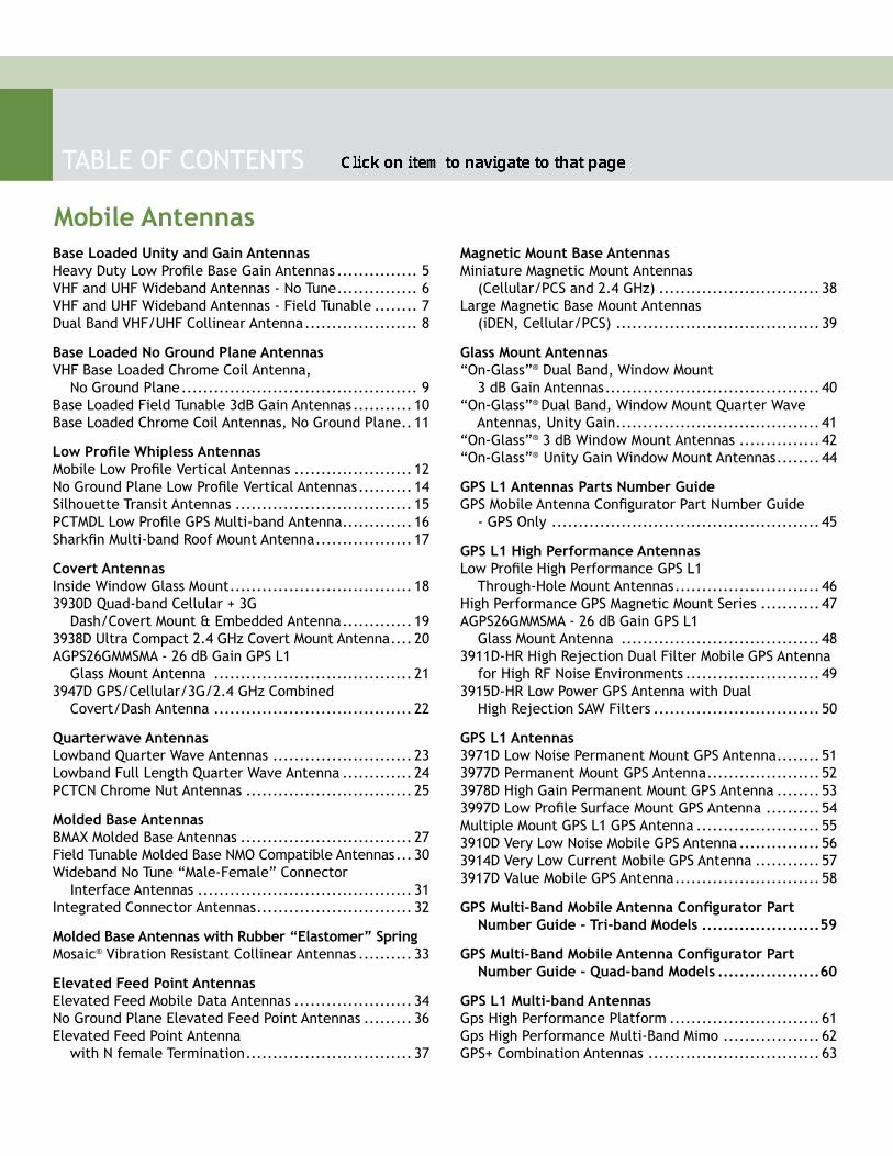
TABLE OF CONTENTS
Mobile AntennasBase Loaded Unity and Gain AntennasHeavy Duty Low Profile Base Gain Antennas ............... 5VHF and UHF Wideband Antennas - No Tune ............... 6VHF and UHF Wideband Antennas - Field Tunable ........ 7Dual Band VHF/UHF Collinear Antenna ..................... 8
Base Loaded No Ground Plane AntennasVHF Base Loaded Chrome Coil Antenna, No Ground Plane ............................................ 9Base Loaded Field Tunable 3dB Gain Antennas ........... 10Base Loaded Chrome Coil Antennas, No Ground Plane .. 11
Low Profile Whipless AntennasMobile Low Profile Vertical Antennas ...................... 12No Ground Plane Low Profile Vertical Antennas .......... 14Silhouette Transit Antennas ................................. 15PCTMDL Low Profile GPS Multi-band Antenna ............. 16Sharkfin Multi-band Roof Mount Antenna .................. 17
Covert AntennasInside Window Glass Mount .................................. 183930D Quad-band Cellular + 3G Dash/Covert Mount & Embedded Antenna ............. 193938D Ultra Compact 2.4 GHz Covert Mount Antenna .... 20AGPS26GMMSMA - 26 dB Gain GPS L1 Glass Mount Antenna ..................................... 213947D GPS/Cellular/3G/2.4 GHz Combined Covert/Dash Antenna ..................................... 22
Quarterwave AntennasLowband Quarter Wave Antennas .......................... 23Lowband Full Length Quarter Wave Antenna ............. 24PCTCN Chrome Nut Antennas ............................... 25
Molded Base AntennasBMAX Molded Base Antennas ................................ 27Field Tunable Molded Base NMO Compatible Antennas ... 30Wideband No Tune “Male-Female” Connector Interface Antennas ........................................ 31Integrated Connector Antennas ............................. 32
Molded Base Antennas with Rubber “Elastomer” SpringMosaic® Vibration Resistant Collinear Antennas .......... 33
Elevated Feed Point AntennasElevated Feed Mobile Data Antennas ...................... 34No Ground Plane Elevated Feed Point Antennas ......... 36Elevated Feed Point Antenna with N female Termination ............................... 37
Magnetic Mount Base AntennasMiniature Magnetic Mount Antennas (Cellular/PCS and 2.4 GHz) .............................. 38Large Magnetic Base Mount Antennas (iDEN, Cellular/PCS) ...................................... 39
Glass Mount Antennas“On-Glass”® Dual Band, Window Mount 3 dB Gain Antennas ........................................ 40“On-Glass”® Dual Band, Window Mount Quarter Wave Antennas, Unity Gain ...................................... 41“On-Glass”® 3 dB Window Mount Antennas ............... 42“On-Glass”® Unity Gain Window Mount Antennas ........ 44
GPS L1 Antennas Parts Number GuideGPS Mobile Antenna Configurator Part Number Guide - GPS Only .................................................. 45
GPS L1 High Performance AntennasLow Profile High Performance GPS L1 Through-Hole Mount Antennas ........................... 46High Performance GPS Magnetic Mount Series ........... 47AGPS26GMMSMA - 26 dB Gain GPS L1 Glass Mount Antenna ..................................... 483911D-HR High Rejection Dual Filter Mobile GPS Antenna for High RF Noise Environments ......................... 493915D-HR Low Power GPS Antenna with Dual High Rejection SAW Filters ............................... 50
GPS L1 Antennas3971D Low Noise Permanent Mount GPS Antenna ........ 513977D Permanent Mount GPS Antenna ..................... 523978D High Gain Permanent Mount GPS Antenna ........ 533997D Low Profile Surface Mount GPS Antenna .......... 54Multiple Mount GPS L1 GPS Antenna ....................... 553910D Very Low Noise Mobile GPS Antenna ............... 563914D Very Low Current Mobile GPS Antenna ............ 573917D Value Mobile GPS Antenna ........................... 58
GPS Multi-Band Mobile Antenna Configurator Part Number Guide - Tri-band Models ......................59
GPS Multi-Band Mobile Antenna Configurator Part Number Guide - Quad-band Models ...................60
GPS L1 Multi-band AntennasGps High Performance Platform ............................ 61Gps High Performance Multi-Band Mimo .................. 62GPS+ Combination Antennas ................................ 63
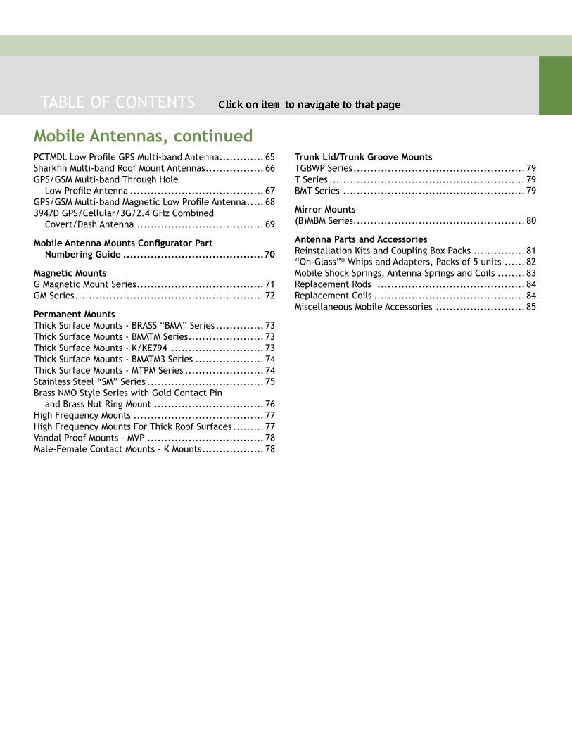
Mobile Antennas, continued
TABLE OF CONTENTS
PCTMDL Low Profile GPS Multi-band Antenna ............. 65Sharkfin Multi-band Roof Mount Antennas ................. 66GPS/GSM Multi-band Through Hole Low Profile Antenna ....................................... 67GPS/GSM Multi-band Magnetic Low Profile Antenna ..... 683947D GPS/Cellular/3G/2.4 GHz Combined Covert/Dash Antenna ..................................... 69
Mobile Antenna Mounts Configurator Part Numbering Guide .........................................70
Magnetic MountsG Magnetic Mount Series ..................................... 71GM Series ....................................................... 72
Permanent MountsThick Surface Mounts - BRASS “BMA” Series .............. 73Thick Surface Mounts - BMATM Series ...................... 73Thick Surface Mounts - K/KE794 ........................... 73Thick Surface Mounts - BMATM3 Series .................... 74Thick Surface Mounts - MTPM Series ....................... 74Stainless Steel “SM” Series .................................. 75Brass NMO Style Series with Gold Contact Pin and Brass Nut Ring Mount ................................ 76High Frequency Mounts ...................................... 77High Frequency Mounts For Thick Roof Surfaces ......... 77Vandal Proof Mounts - MVP .................................. 78Male-Female Contact Mounts - K Mounts .................. 78
Trunk Lid/Trunk Groove MountsTGBWP Series .................................................. 79T Series ......................................................... 79BMT Series ..................................................... 79
Mirror Mounts(B)MBM Series .................................................. 80
Antenna Parts and AccessoriesReinstallation Kits and Coupling Box Packs ............... 81“On-Glass”® Whips and Adapters, Packs of 5 units ...... 82Mobile Shock Springs, Antenna Springs and Coils ........ 83Replacement Rods ........................................... 84Replacement Coils ............................................ 84Miscellaneous Mobile Accessories .......................... 85
t TOC
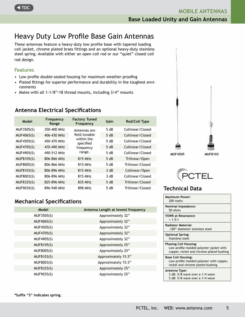
MUF8103
Technical Data Maximum Power:
200 watts
Nominal Impedance:50 ohms
VSWR at Resonance:< 1.5:1
Radiator Material:.100” diameter stainless steel
Optional Spring: Stainless steel
Phasing Coil Housing:Low profile molded polymer jacket with copper, nickel and chrome plated bushing
Base Coil Housing:Low profile molded polymer with copper, nickel and chrome plated bushing
Antenna Type: 3 dB: 5/8 wave over a 1/4 wave5 dB: 5/8 wave over a 1/4 wave
MUF4505
Model Frequency Range
Factory Tuned Frequency Gain Rod/Coil Type
MUF3505(S) 350-400 MHz Antennas are field tunable within the specified frequency
range.
5 dB Collinear/Closed
MUF4065(S) 406-430 MHz 5 dB Collinear/Closed
MUF4505(S) 450-470 MHz 5 dB Collinear/Closed
MUF4705(S) 470-490 MHz 5 dB Collinear/Closed
MUF4905(S) 490-512 MHz 5 dB Collinear/Closed
MUF8105(S) 806-866 MHz 815 MHz 5 dB Trilinear/Open
MUF8005(S) 806-866 MHz 815 MHz 5 dB Trilinear/Closed
MUF8103(S) 806-896 MHz 815 MHz 3 dB Collinear/Open
MUF8003(S) 806-896 MHz 815 MHz 3 dB Collinear/Closed
MUF8325(S) 825-896 MHz 835 MHz 5 dB Trilinear/Closed
MUF9035(S) 896-940 MHz 898 MHz 5 dB Trilinear/Closed
Antenna Electrical Specifications
Heavy Duty Low Profile Base Gain AntennasThese antennas feature a heavy-duty low profile base with tapered loading coil jacket, chrome plated brass fittings and an optional heavy-duty stainless steel spring. Available with either an open coil rod or our “quiet” closed coil rod design.
Features• Low profile double-sealed housing for maximum weather-proofing• Plated fittings for superior performance and durability in the toughest envi-
ronments• Mates with all 1-1/8”-18 thread mounts, including 3/4” mounts
*Suffix “S” indicates spring.
Model Antenna Length at lowest frequency
MUF3505(S) Approximately 32”
MUF4065(S) Approximately 32”
MUF4505(S) Approximately 32”
MUF4705(S) Approximately 32”
MUF4905(S) Approximately 32”
MUF8105(S) Approximately 25”
MUF8005(S) Approximately 25”
MUF8103(S) Approximately 15.5”
MUF8003(S) Approximately 15.5”
MUF8325(S) Approximately 25”
MUF9035(S) Approximately 25”
Mechanical Specifications
MOBILE ANTENNASBase Loaded Unity and Gain Antennas
PCTEL, Inc. WEB: www.antenna.com 5
t TOCMOBILE ANTENNASBase Loaded Unity and Gain Antennas
Technical Data Maximum Power:
200 watts (UHF)160 watts (VHF)
Nominal Impedance:50 ohms
VSWR:< 2.0:1
Radiator Material:.100” diameter stainless steel
Spring:Stainless steel
Phasing Coil Housing:Molded polymer jacket with bright or black chrome plated bushing
Base Coil Housing:Molded polymer jacket with copper, nickel and chrome plated bushing
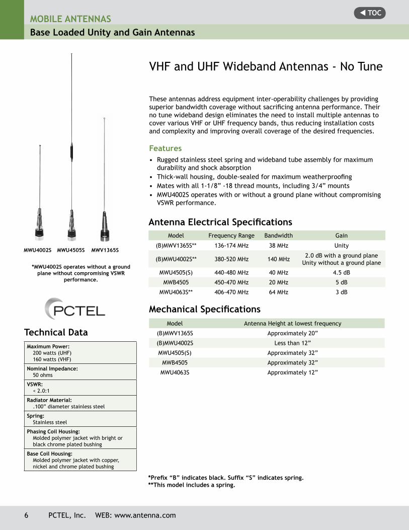
MWU4002S MWU4505S MWV1365S
VHF and UHF Wideband Antennas - No Tune
These antennas address equipment inter-operability challenges by providing superior bandwidth coverage without sacrificing antenna performance. Their no tune wideband design eliminates the need to install multiple antennas to cover various VHF or UHF frequency bands, thus reducing installation costs and complexity and improving overall coverage of the desired frequencies.
Features• Rugged stainless steel spring and wideband tube assembly for maximum
durability and shock absorption• Thick-wall housing, double-sealed for maximum weatherproofing• Mates with all 1-1/8” -18 thread mounts, including 3/4” mounts• MWU4002S operates with or without a ground plane without compromising
VSWR performance.
*Prefix “B” indicates black. Suffix “S” indicates spring.**This model includes a spring.
Antenna Electrical Specifications Model Frequency Range Bandwidth Gain
(B)MWV1365S** 136-174 MHz 38 MHz Unity
(B)MWU4002S** 380-520 MHz 140 MHz 2.0 dB with a ground plane Unity without a ground plane
MWU4505(S) 440-480 MHz 40 MHz 4.5 dB
MWB4505 450-470 MHz 20 MHz 5 dB
MWU4063S** 406-470 MHz 64 MHz 3 dB
Mechanical Specifications Model Antenna Height at lowest frequency
(B)MWV1365S Approximately 20”
(B)MWU4002S Less than 12”
MWU4505(S) Approximately 32”
MWB4505 Approximately 32”
MWU4063S Approximately 12”
*MWU4002S operates without a ground plane without compromising VSWR
performance.
6 PCTEL, Inc. WEB: www.antenna.com
t TOC
Technical Data Maximum Power:
150 watts100 watts (ASPC201L)
Nominal Impedance:50 ohms
VSWR at Resonance:< 1.5:1 (ASPR795 and ASPC201L)< 2.0:1 (all other models)
Radiator Material:0.125” diameter, 17-7PH stainless steel (Models MWV1322HD(S) and ASPR7495 only)0.072” diameter, 17-7PH stainless (ASPC201L)0.046” diameter, stainless steel (ASPR795).100”-.062” diameter tapered stainless steel (all other models)
Spring Material (if available with the antenna):Stainless steel
Base and Fittings:Aluminum, plated steel and brass (ASPR795)
Base Coil Housing:Molded polymer jacket with copper, nickel and chrome plated bushing
Antenna Type:Base loaded 1/2 wave (MWV models) 1/4 Wave (all models)
Mounting Method: 1-1/8” -18 thread mobile mounts, includ-ing 3/4” hole mounts (all models except ASPC201L) 3/8” hole snap-in mounts (ASPC201L only)
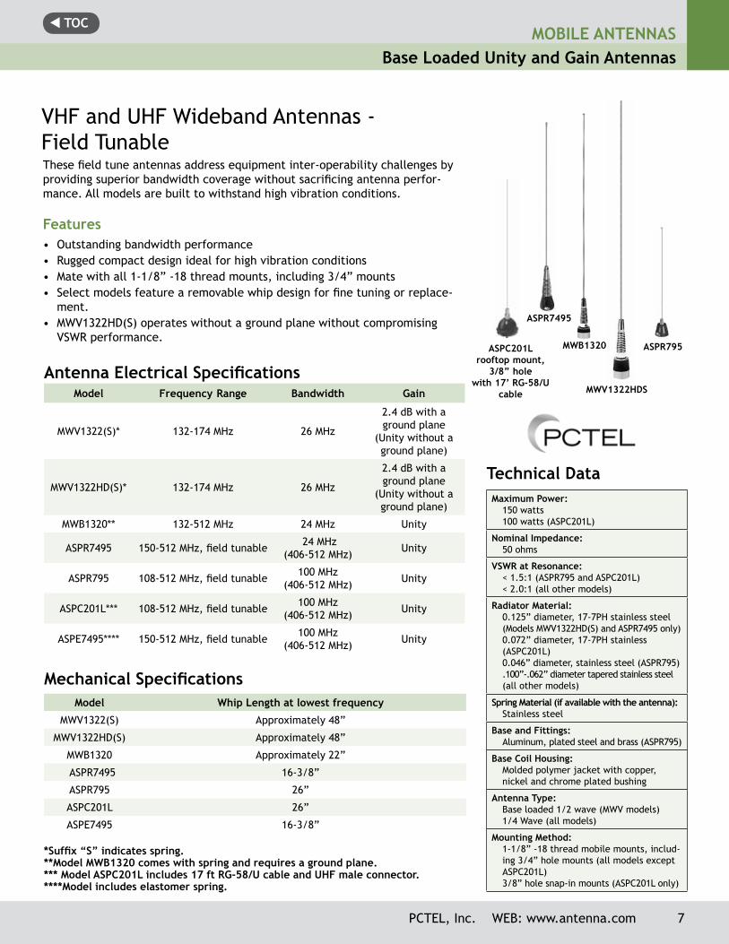
MWV1322HDS
MOBILE ANTENNASBase Loaded Unity and Gain Antennas
VHF and UHF Wideband Antennas - Field TunableThese field tune antennas address equipment inter-operability challenges by providing superior bandwidth coverage without sacrificing antenna perfor-mance. All models are built to withstand high vibration conditions.
Features• Outstanding bandwidth performance• Rugged compact design ideal for high vibration conditions• Mate with all 1-1/8” -18 thread mounts, including 3/4” mounts• Select models feature a removable whip design for fine tuning or replace-
ment.• MWV1322HD(S) operates without a ground plane without compromising
VSWR performance.
*Suffix “S” indicates spring.**Model MWB1320 comes with spring and requires a ground plane.*** Model ASPC201L includes 17 ft RG-58/U cable and UHF male connector. ****Model includes elastomer spring.
ASPR7495
ASPC201L rooftop mount,
3/8” hole with 17’ RG-58/U
cable
ASPR795MWB1320
Antenna Electrical Specifications
Mechanical Specifications
Model Frequency Range Bandwidth Gain
MWV1322(S)* 132-174 MHz 26 MHz
2.4 dB with a ground plane
(Unity without a ground plane)
MWV1322HD(S)* 132-174 MHz 26 MHz
2.4 dB with a ground plane
(Unity without a ground plane)
MWB1320** 132-512 MHz 24 MHz Unity
ASPR7495 150-512 MHz, field tunable 24 MHz (406-512 MHz) Unity
ASPR795 108-512 MHz, field tunable 100 MHz (406-512 MHz) Unity
ASPC201L*** 108-512 MHz, field tunable 100 MHz (406-512 MHz) Unity
ASPE7495**** 150-512 MHz, field tunable 100 MHz (406-512 MHz) Unity
Model Whip Length at lowest frequency
MWV1322(S) Approximately 48”
MWV1322HD(S) Approximately 48”
MWB1320 Approximately 22”
ASPR7495 16-3/8”
ASPR795 26”
ASPC201L 26”
ASPE7495 16-3/8”
PCTEL, Inc. WEB: www.antenna.com 7
t TOCMOBILE ANTENNASBase Loaded Unity and Gain Antennas
* Suffix “S” indicates spring, which is not a retrofit option. Please indicate at time of order.
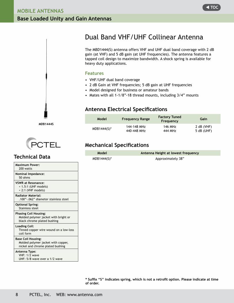
Dual Band VHF/UHF Collinear Antenna
The MBD1444(S) antenna offers VHF and UHF dual band coverage with 2 dB gain (at VHF) and 5 dB gain (at UHF fre quen cies). The antenna features a tapped coil design to maximize bandwidth. A shock spring is available for heavy duty applications.
Features• VHF/UHF dual band coverage• 2 dB Gain at VHF frequencies; 5 dB gain at UHF frequencies• Model designed for business or amateur bands• Mates with all 1-1/8”-18 thread mounts, including 3/4” mounts
Model Frequency Range Factory Tuned Frequency Gain
MDB1444(S)* 144-148 MHz 440-448 MHz
146 MHz444 MHz
2 dB (VHF)5 dB (UHF)
Antenna Electrical Specifications
Mechanical SpecificationsModel Antenna Height at lowest frequency
MDB1444(S)* Approximately 38”
MDB1444S
Technical Data Maximum Power:
200 watts
Nominal Impedance:50 ohms
VSWR at Resonance:< 1.5:1 (UHF models)< 2:1 (VHF models)
Radiator Material:.100”-.062” diameter stainless steel
Optional Spring:Stainless steel
Phasing Coil Housing:Molded polymer jacket with bright or black chrome plated bushing
Loading Coil:Tinned copper wire wound on a low-loss coil form
Base Coil Housing:Molded polymer jacket with copper, nickel and chrome plated bushing
Antenna Type:VHF: 1/2 waveUHF: 5/8 wave over a 1/2 wave
8 PCTEL, Inc. WEB: www.antenna.com
t TOCMOBILE ANTENNAS
Base Loaded No Ground Plane Antennas
PCTEL, Inc. WEB: www.antenna.com 9
*Suffix “S” (Spring) is not a retrofit option, please indicate at time of order.
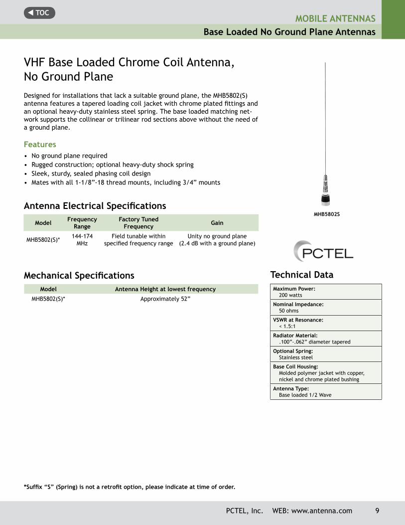
VHF Base Loaded Chrome Coil Antenna, No Ground PlaneDesigned for installations that lack a suitable ground plane, the MHB5802(S) antenna features a ta pered loading coil jacket with chrome plated fittings and an optional heavy-duty stainless steel spring. The base loaded matching net-work supports the collinear or trilinear rod sections above without the need of a ground plane.
Features• No ground plane required• Rugged construction; optional heavy-duty shock spring• Sleek, sturdy, sealed phasing coil design• Mates with all 1-1/8”-18 thread mounts, including 3/4” mounts
Antenna Electrical Specifications
Mechanical Specifications
Model Frequency Range
Factory Tuned Frequency Gain
MHB5802(S)* 144-174 MHz
Field tunable within specified frequency range
Unity no ground plane (2.4 dB with a ground plane)
Model Antenna Height at lowest frequency
MHB5802(S)* Approximately 52”
MHB5802S
Technical Data Maximum Power:
200 watts
Nominal Impedance:50 ohms
VSWR at Resonance:< 1.5:1
Radiator Material:.100”-.062” diameter tapered
Optional Spring:Stainless steel
Base Coil Housing:Molded polymer jacket with copper, nickel and chrome plated bushing
Antenna Type:Base loaded 1/2 Wave
t TOCMOBILE ANTENNASBase Loaded No Ground Plane Antennas
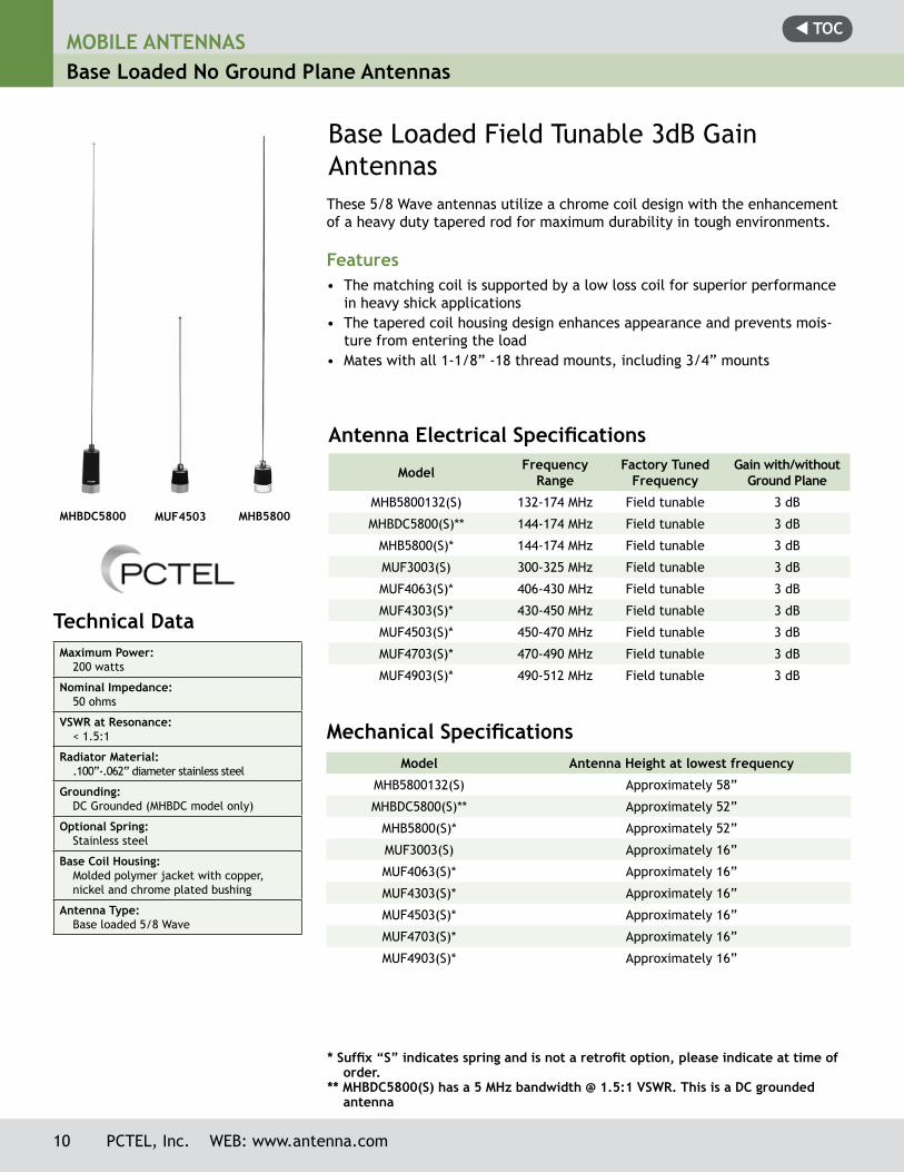
MHB5800
Technical Data Maximum Power:
200 watts
Nominal Impedance:50 ohms
VSWR at Resonance:< 1.5:1
Radiator Material:.100”-.062” diameter stainless steel
Grounding:DC Grounded (MHBDC model only)
Optional Spring:Stainless steel
Base Coil Housing:Molded polymer jacket with copper, nickel and chrome plated bushing
Antenna Type:Base loaded 5/8 Wave
MHBDC5800 MUF4503
Base Loaded Field Tunable 3dB Gain AntennasThese 5/8 Wave antennas utilize a chrome coil design with the enhancement of a heavy duty tapered rod for maximum durability in tough environments.
Features• The matching coil is supported by a low loss coil for superior performance
in heavy shick applications• The tapered coil housing design enhances appearance and prevents mois-
ture from entering the load• Mates with all 1-1/8” -18 thread mounts, including 3/4” mounts
Antenna Electrical Specifications
* Suffix “S” indicates spring and is not a retrofit option, please indicate at time of order. ** MHBDC5800(S) has a 5 MHz bandwidth @ 1.5:1 VSWR. This is a DC grounded antenna
Model Frequency Range
Factory Tuned Frequency
Gain with/without Ground Plane
MHB5800132(S) 132-174 MHz Field tunable 3 dB
MHBDC5800(S)** 144-174 MHz Field tunable 3 dB
MHB5800(S)* 144-174 MHz Field tunable 3 dB
MUF3003(S) 300-325 MHz Field tunable 3 dB
MUF4063(S)* 406-430 MHz Field tunable 3 dB
MUF4303(S)* 430-450 MHz Field tunable 3 dB
MUF4503(S)* 450-470 MHz Field tunable 3 dB
MUF4703(S)* 470-490 MHz Field tunable 3 dB
MUF4903(S)* 490-512 MHz Field tunable 3 dB
Mechanical SpecificationsModel Antenna Height at lowest frequency
MHB5800132(S) Approximately 58”
MHBDC5800(S)** Approximately 52”
MHB5800(S)* Approximately 52”
MUF3003(S) Approximately 16”
MUF4063(S)* Approximately 16”
MUF4303(S)* Approximately 16”
MUF4503(S)* Approximately 16”
MUF4703(S)* Approximately 16”
MUF4903(S)* Approximately 16”
10 PCTEL, Inc. WEB: www.antenna.com
t TOC
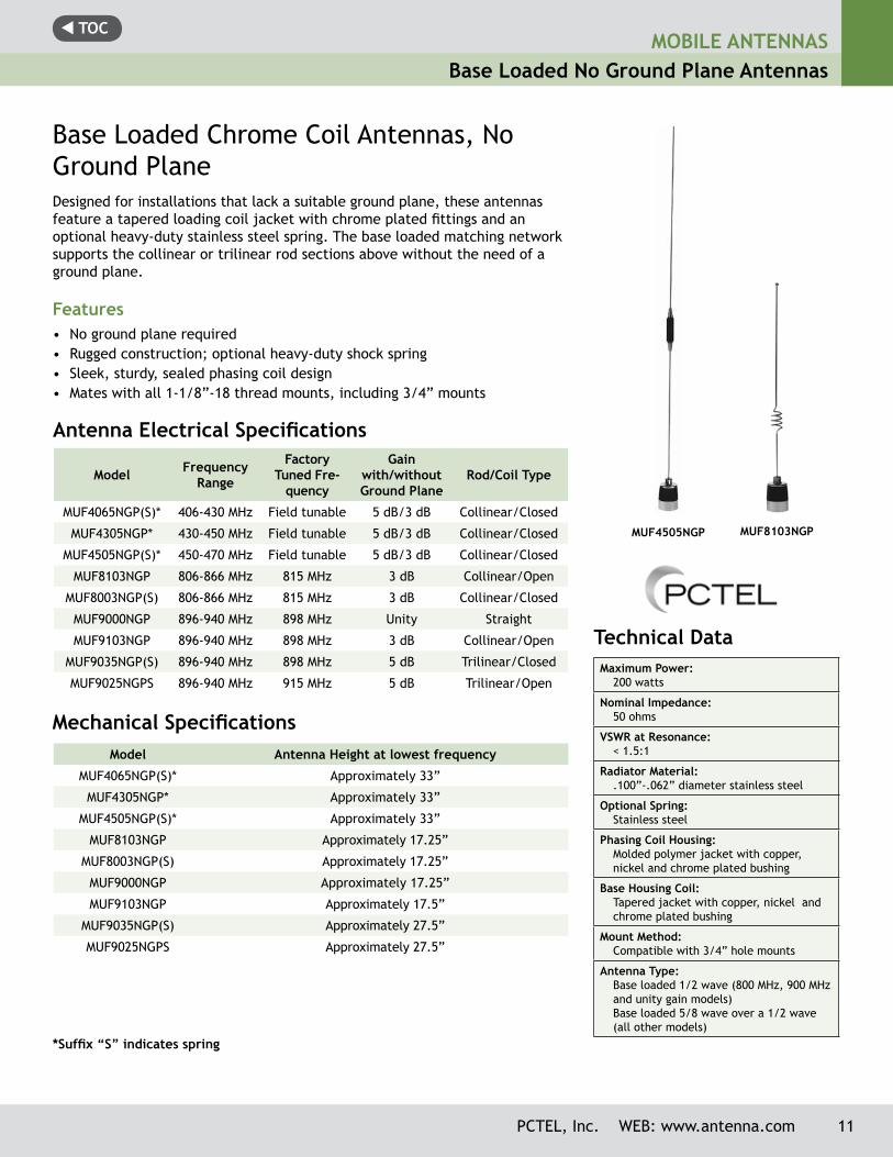
MUF4505NGP MUF8103NGP
Technical Data Maximum Power:
200 watts
Nominal Impedance:50 ohms
VSWR at Resonance:< 1.5:1
Radiator Material:.100”-.062” diameter stainless steel
Optional Spring: Stainless steel
Phasing Coil Housing:Molded polymer jacket with copper, nickel and chrome plated bushing
Base Housing Coil:Tapered jacket with copper, nickel and chrome plated bushing
Mount Method:Compatible with 3/4” hole mounts
Antenna Type:Base loaded 1/2 wave (800 MHz, 900 MHz and unity gain models) Base loaded 5/8 wave over a 1/2 wave (all other models)
Model Frequency Range
Factory Tuned Fre-
quency
Gainwith/withoutGround Plane
Rod/Coil Type
MUF4065NGP(S)* 406-430 MHz Field tunable 5 dB/3 dB Collinear/Closed
MUF4305NGP* 430-450 MHz Field tunable 5 dB/3 dB Collinear/Closed
MUF4505NGP(S)* 450-470 MHz Field tunable 5 dB/3 dB Collinear/Closed
MUF8103NGP 806-866 MHz 815 MHz 3 dB Collinear/Open
MUF8003NGP(S) 806-866 MHz 815 MHz 3 dB Collinear/Closed
MUF9000NGP 896-940 MHz 898 MHz Unity Straight
MUF9103NGP 896-940 MHz 898 MHz 3 dB Collinear/Open
MUF9035NGP(S) 896-940 MHz 898 MHz 5 dB Trilinear/Closed
MUF9025NGPS 896-940 MHz 915 MHz 5 dB Trilinear/Open
Base Loaded Chrome Coil Antennas, No Ground PlaneDesigned for installations that lack a suitable ground plane, these antennas feature a ta pered loading coil jacket with chrome plated fittings and an optional heavy-duty stainless steel spring. The base loaded matching network supports the collinear or trilinear rod sections above without the need of a ground plane.
Features• No ground plane required• Rugged construction; optional heavy-duty shock spring• Sleek, sturdy, sealed phasing coil design• Mates with all 1-1/8”-18 thread mounts, including 3/4” mounts
Antenna Electrical Specifications
Mechanical Specifications
*Suffix “S” indicates spring
Model Antenna Height at lowest frequency
MUF4065NGP(S)* Approximately 33”
MUF4305NGP* Approximately 33”
MUF4505NGP(S)* Approximately 33”
MUF8103NGP Approximately 17.25”
MUF8003NGP(S) Approximately 17.25”
MUF9000NGP Approximately 17.25”
MUF9103NGP Approximately 17.5”
MUF9035NGP(S) Approximately 27.5”
MUF9025NGPS Approximately 27.5”
PCTEL, Inc. WEB: www.antenna.com 11
MOBILE ANTENNASBase Loaded No Ground Plane Antennas
t TOCMOBILE ANTENNASLow Profile Whipless Antennas
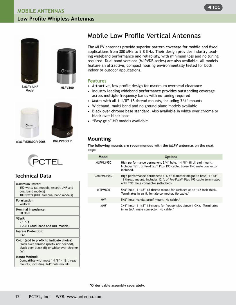
Mobile Low Profile Vertical AntennasThe MLPV antennas provide superior pattern coverage for mobile and fixed applications from 380 MHz to 5.8 GHz. Their design provides industry lead-ing wideband performance and reliability, with minimum loss and no tuning required. Dual band versions (MLPVDB series) are also available. All models feature an attractive, compact housing environmentally tested for both indoor or outdoor applications.
Features• Attractive, low profile design for maximum overhead clearance• Industry leading wideband performance provides outstanding coverage
across multiple frequency bands with no tuning required• Mates with all 1-1/8”-18 thread mounts, including 3/4” mounts• Wideband, multi-band and no ground plane models available • Black over chrome base standard. Also available in white over chrome or
black over black base• “Easy grip” HD models available
Technical Data Maximum Power:
150 watts (all models, except UHF and dual band models)100 watts (UHF and dual band models)
Polarization:Vertical
Nominal Impedance:50 Ohm
VSWR:< 1.5:1< 2.0:1 (dual-band and UHF models)
Ingress Protection:IP66
Color (add to prefix to indicate choice):Black over chrome (prefix not needed), black over black (B) or white over chrome (W).
Mount Method:Compatible with most 1-1/8” - 18 thread mounts, including 3/4” hole mounts
MountingThe following mounts are recommended with the MLPV antennas on the next page:
Model Options
MLFML195C High performance permanent 3/4” hole, 1-1/8”-18 thread mount. Includes 17 ft of Pro-FlexTM Plus 195 cable. Loose TNC male connector included.
GMLFML195C High performance permanent 3-1/4” diameter magnetic base, 1-1/8”-18 thread mount. Includes 12 ft of Pro-FlexTM Plus 195 cable terminated with TNC male connector (attached).
MTPM800 5/8” hole, 1-1/8”-18 thread mount for surfaces up to 1/2-inch thick. Terminates in an N, female connector. No cable.*
MVP 5/8” hole, vandal proof mount. No cable.*
MMF 3/4” hole, 1-1/8”-18 mount for frequencies above 1 GHz. Terminates in an SMA, male connector. No cable.*
*Order cable assembly separately.
BMLPV UHF Model
WMLPVDB800/1900S
MLPV800
BMLPV800HD
12 PCTEL, Inc. WEB: www.antenna.com
t TOCMOBILE ANTENNAS
Low Profile Whipless Antennas
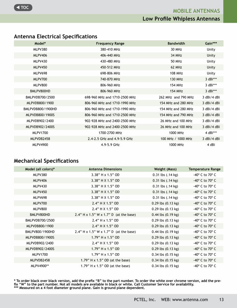
Antenna Electrical Specifications Model* Frequency Range Bandwidth Gain***
MLPV380 380-410 MHz 30 MHz Unity
MLPV406 406-440 MHz 34 MHz Unity
MLPV430 430-480 MHz 50 MHz Unity
MLPV450 450-512 MHz 62 MHz Unity
MLPV698 698-806 MHz 108 MHz Unity
MLPV700 740-870 MHz 130 MHz 3 dBi***
MLPV800 806-960 MHz 154 MHz 3 dBi***
BMLPV800HD 806-960 MHz 154 MHz 3 dBi***
BMLPVDB700/2500 698-960 MHz and 1710-2500 MHz 262 MHz and 790 MHz 3 dBi/4 dBi
MLPVDB800/1900 806-960 MHz and 1710-1990 MHz 154 MHz and 280 MHz 3 dBi/4 dBi
BMLPVDB800/1900HD 806-960 MHz and 1710-1990 MHz 154 MHz and 280 MHz 3 dBi/4 dBi
MLPVDB800/1900S 806-960 MHz and 1710-2500 MHz 154 MHz and 790 MHz 3 dBi/4 dBi
MLPVDB902/2400 902-928 MHz and 2400-2500 MHz 26 MHz and 100 MHz 3 dBi/4 dBi
MLPVDB902/2400S 902-928 MHz and 2400-2500 MHz 26 MHz and 100 MHz 3 dBi/4 dBi
MLPV1700 1700-2700 MHz 1000 MHz 4 dBi***
MLPVDB2458 2.4-2.5 GHz and 4.9-5.9 GHz 100 MHz / 1000 MHz 3 dBi/4 dBi
MLPV4900 4.9-5.9 GHz 1000 MHz 4 dBi
Mechanical SpecificationsModel (all colors)* Antenna Dimensions Weight (Mass) Temperature Range
MLPV380 3.38” H x 1.5” OD 0.31 lbs (.14 kg) -40º C to 70º C
MLPV406 3.38” H X 1.5” OD 0.31 lbs (.14 kg) -40º C to 70º C
MLPV430 3.38” H X 1.5” OD 0.31 lbs (.14 kg) -40º C to 70º C
MLPV450 3.38” H X 1.5” OD 0.31 lbs (.14 kg) -40º C to 70º C
MLPV698 3.38” H X 1.5” OD 0.31 lbs (.14 kg) -40º C to 70º C
MLPV700 2.4” H X 1.5” OD 0.29 lbs (0.13 kg) -40º C to 70º C
MLPV800 2.4” H X 1.5” OD 0.29 lbs (0.13 kg) -40º C to 70º C
BMLPV800HD 2.4” H x 1.5” W x 1.7” D (at the base) 0.44 lbs (0.19 kg) -40º C to 70º C
BMLPVDB700/2500 2.4” H x 1.5” OD 0.29 lbs (0.13 kg) -40º C to 70º C
MLPVDB800/1900 2.4” H X 1.5” OD 0.29 lbs (0.13 kg) -40º C to 70º C
BMLPV800/1900HD 2.4” H x 1.5” W x 1.7” D (at the base) 0.44 lbs (0.19 kg) -40º C to 70º C
MLPVDB800/1900S 1.79” H x 1.5” OD 0.29 lbs (0.13 kg) -40º C to 70º C
MLPVDB902/2400 2.4” H X 1.5” OD 0.29 lbs (0.13 kg) -40º C to 70º C
MLPVDB902/2400S 1.79” H x 1.5” OD 0.29 lbs (0.13 kg) -40º C to 70º C
MLPV1700 1.79” H x 1.5” OD 0.34 lbs (0.15 kg) -40º C to 70º C
MLPVDB2458 1.79” H x 1.5” OD (at the base) 0.34 lbs (0.15 kg) -40º C to 70º C
MLPV4900** 1.79” H x 1.5” OD (at the base) 0.34 lbs (0.15 kg) -40º C to 70º C
* To order black over black version, add the prefix “B” to the part number. To order the white over chrome version, add the pre-fix “W” to the part number. Not all models are available in black or white. Call Customer Service for availability.*** Measured on a 4 foot diameter ground plane. Gain is ground plane dependent.
PCTEL, Inc. WEB: www.antenna.com 13
t TOCMOBILE ANTENNASLow Profile Whipless Antennas
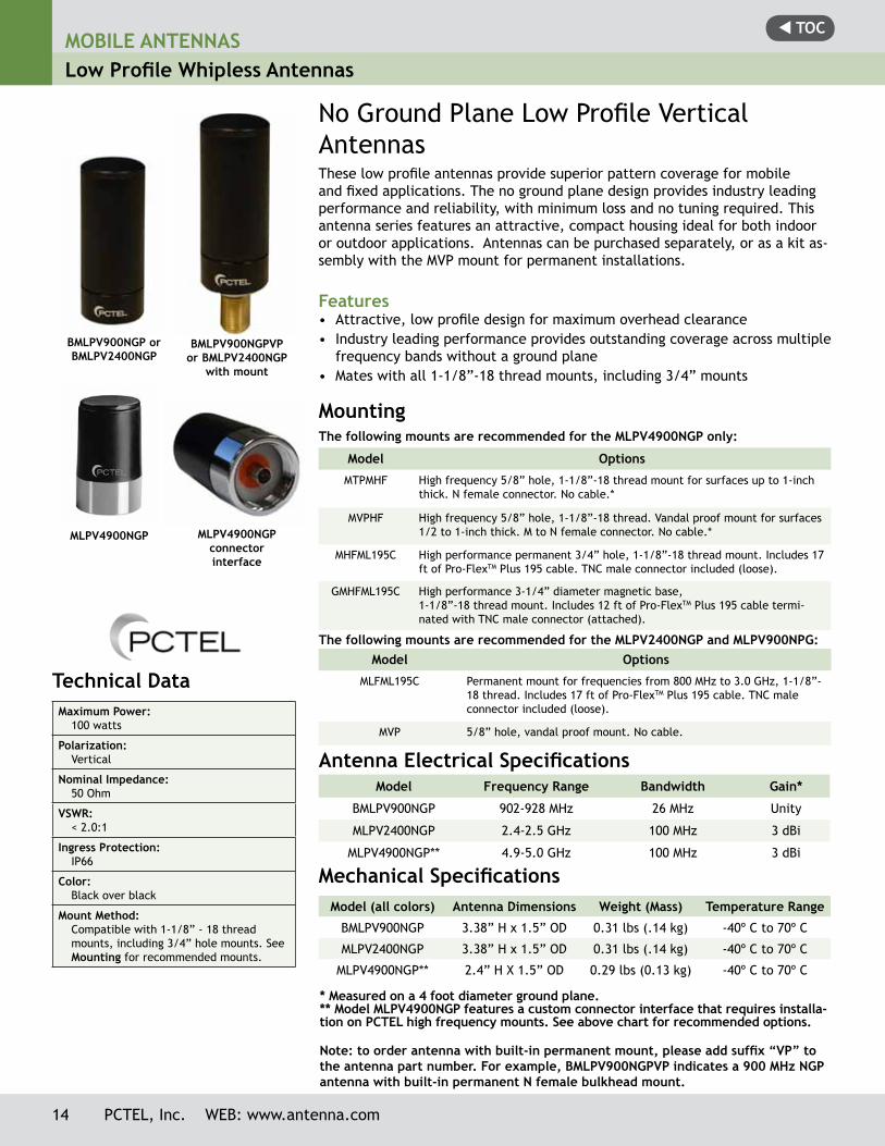
No Ground Plane Low Profile Vertical AntennasThese low profile antennas provide superior pattern coverage for mobile and fixed applications. The no ground plane design provides industry leading performance and reliability, with minimum loss and no tuning required. This antenna series features an attractive, compact housing ideal for both indoor or outdoor applications. Antennas can be purchased separately, or as a kit as-sembly with the MVP mount for permanent installations.
Features• Attractive, low profile design for maximum overhead clearance• Industry leading performance provides outstanding coverage across multiple
frequency bands without a ground plane• Mates with all 1-1/8”-18 thread mounts, including 3/4” mounts
Antenna Electrical Specifications Model Frequency Range Bandwidth Gain*
BMLPV900NGP 902-928 MHz 26 MHz Unity
MLPV2400NGP 2.4-2.5 GHz 100 MHz 3 dBi
MLPV4900NGP** 4.9-5.0 GHz 100 MHz 3 dBi
Mechanical SpecificationsModel (all colors) Antenna Dimensions Weight (Mass) Temperature Range
BMLPV900NGP 3.38” H x 1.5” OD 0.31 lbs (.14 kg) -40º C to 70º C
MLPV2400NGP 3.38” H x 1.5” OD 0.31 lbs (.14 kg) -40º C to 70º C
MLPV4900NGP** 2.4” H X 1.5” OD 0.29 lbs (0.13 kg) -40º C to 70º C
* Measured on a 4 foot diameter ground plane.** Model MLPV4900NGP features a custom connector interface that requires installa-tion on PCTEL high frequency mounts. See above chart for recommended options.
Note: to order antenna with built-in permanent mount, please add suffix “VP” to the antenna part number. For example, BMLPV900NGPVP indicates a 900 MHz NGP antenna with built-in permanent N female bulkhead mount.
Technical Data Maximum Power:
100 watts
Polarization:Vertical
Nominal Impedance:50 Ohm
VSWR:< 2.0:1
Ingress Protection:IP66
Color:Black over black
Mount Method:Compatible with 1-1/8” - 18 thread mounts, including 3/4” hole mounts. See Mounting for recommended mounts.
BMLPV900NGP or BMLPV2400NGP
BMLPV900NGPVP or BMLPV2400NGP
with mount
MLPV4900NGP connector interface
MLPV4900NGP
14 PCTEL, Inc. WEB: www.antenna.com
Model Options
MTPMHF High frequency 5/8” hole, 1-1/8”-18 thread mount for surfaces up to 1-inch thick. N female connector. No cable.*
MVPHF High frequency 5/8” hole, 1-1/8”-18 thread. Vandal proof mount for surfaces 1/2 to 1-inch thick. M to N female connector. No cable.*
MHFML195C High performance permanent 3/4” hole, 1-1/8”-18 thread mount. Includes 17 ft of Pro-FlexTM Plus 195 cable. TNC male connector included (loose).
GMHFML195C High performance 3-1/4” diameter magnetic base, 1-1/8”-18 thread mount. Includes 12 ft of Pro-FlexTM Plus 195 cable termi-nated with TNC male connector (attached).
Mounting The following mounts are recommended for the MLPV4900NGP only:
Model Options
MLFML195C Permanent mount for frequencies from 800 MHz to 3.0 GHz, 1-1/8”-18 thread. Includes 17 ft of Pro-FlexTM Plus 195 cable. TNC male connector included (loose).
MVP 5/8” hole, vandal proof mount. No cable.
The following mounts are recommended for the MLPV2400NGP and MLPV900NPG:
t TOC
PCTEL, Inc. WEB: www.antenna.com 15
MOBILE ANTENNASLow Profile Whipless Antennas
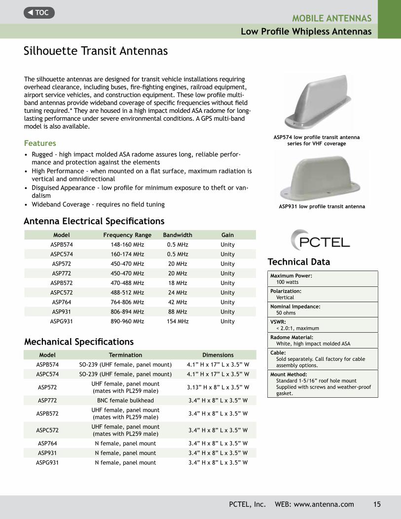
Silhouette Transit Antennas
The silhouette antennas are designed for transit vehicle installations requiring overhead clearance, including buses, fire-fighting engines, railroad equipment, airport service vehicles, and construction equipment. These low profile multi-band antennas provide wideband coverage of specific frequencies without field tuning required.* They are housed in a high impact molded ASA radome for long-lasting performance under severe environmental conditions. A GPS multi-band model is also available.
Features• Rugged - high impact molded ASA radome assures long, reliable perfor-
mance and protection against the elements• High Performance - when mounted on a flat surface, maximum radiation is
vertical and omnidirectional• Disguised Appearance - low profile for minimum exposure to theft or van-
dalism• Wideband Coverage - requires no field tuning
Antenna Electrical Specifications Model Frequency Range Bandwidth Gain
ASPB574 148-160 MHz 0.5 MHz Unity
ASPC574 160-174 MHz 0.5 MHz Unity
ASP572 450-470 MHz 20 MHz Unity
ASP772 450-470 MHz 20 MHz Unity
ASPB572 470-488 MHz 18 MHz Unity
ASPC572 488-512 MHz 24 MHz Unity
ASP764 764-806 MHz 42 MHz Unity
ASP931 806-894 MHz 88 MHz Unity
ASPG931 890-960 MHz 154 MHz Unity
Model Termination Dimensions
ASPB574 SO-239 (UHF female, panel mount) 4.1” H x 17” L x 3.5” W
ASPC574 SO-239 (UHF female, panel mount) 4.1” H x 17” L x 3.5” W
ASP572 UHF female, panel mount(mates with PL259 male) 3.13” H x 8” L x 3.5” W
ASP772 BNC female bulkhead 3.4” H x 8” L x 3.5” W
ASPB572 UHF female, panel mount(mates with PL259 male) 3.4” H x 8” L x 3.5” W
ASPC572 UHF female, panel mount(mates with PL259 male) 3.4” H x 8” L x 3.5” W
ASP764 N female, panel mount 3.4” H x 8” L x 3.5” W
ASP931 N female, panel mount 3.4” H x 8” L x 3.5” W
ASPG931 N female, panel mount 3.4” H x 8” L x 3.5” W
Mechanical Specifications
ASP574 low profile transit antenna series for VHF coverage
Technical Data Maximum Power:
100 watts
Polarization: Vertical
Nominal Impedance: 50 ohms
VSWR: < 2.0:1, maximum
Radome Material: White, high impact molded ASA
Cable: Sold separately. Call factory for cable assembly options.
Mount Method:Standard 1-5/16” roof hole mountSupplied with screws and weather-proof gasket.
ASP931 low profile transit antenna
t TOCMOBILE ANTENNASLow Profile Whipless Antennas
16 PCTEL, Inc. WEB: www.antenna.com
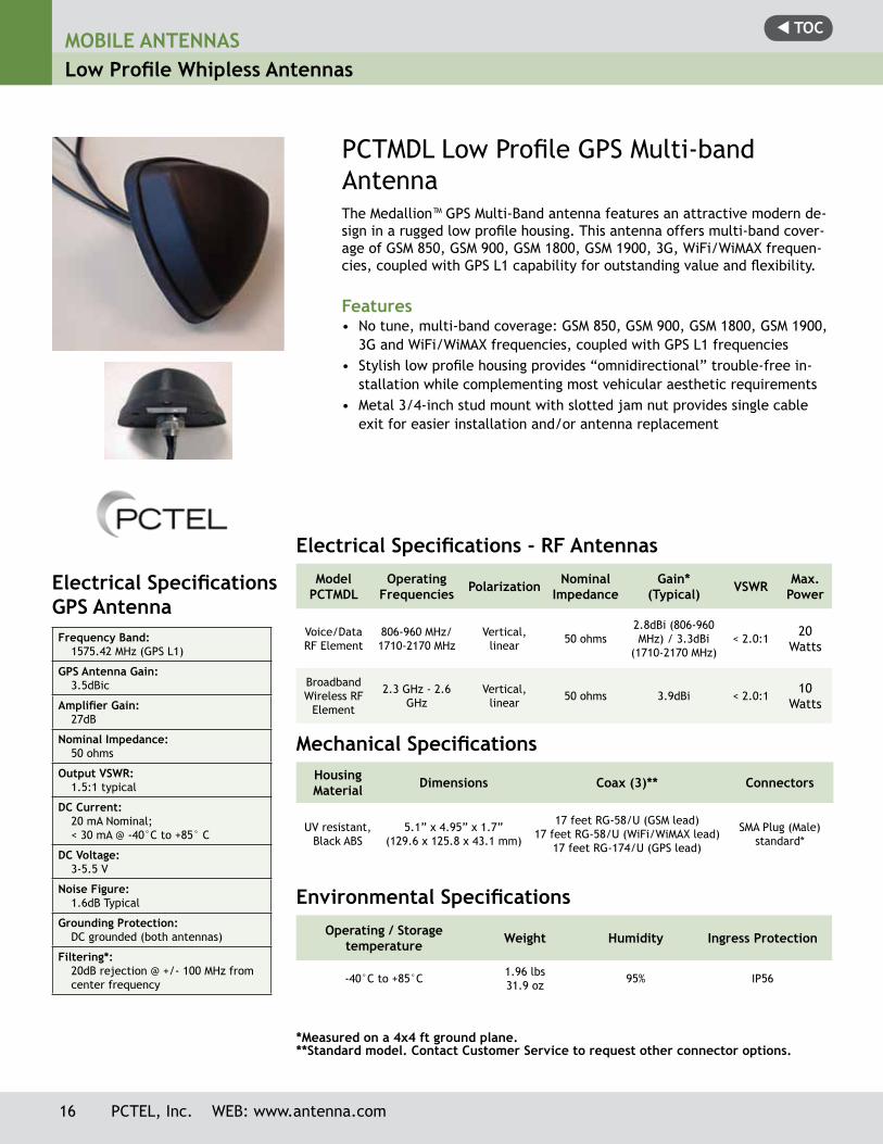
PCTMDL Low Profile GPS Multi-band AntennaThe Medallion™ GPS Multi-Band antenna features an attractive modern de-sign in a rugged low profile housing. This antenna offers multi-band cover-age of GSM 850, GSM 900, GSM 1800, GSM 1900, 3G, WiFi/WiMAX frequen-cies, coupled with GPS L1 capability for outstanding value and flexibility.
Features• No tune, multi-band coverage: GSM 850, GSM 900, GSM 1800, GSM 1900,
3G and WiFi/WiMAX frequencies, coupled with GPS L1 frequencies• Stylish low profile housing provides “omnidirectional” trouble-free in-
stallation while complementing most vehicular aesthetic requirements• Metal 3/4-inch stud mount with slotted jam nut provides single cable
exit for easier installation and/or antenna replacement
Electrical Specifications GPS AntennaFrequency Band:
1575.42 MHz (GPS L1)
GPS Antenna Gain:3.5dBic
Amplifier Gain:27dB
Nominal Impedance:50 ohms
Output VSWR:1.5:1 typical
DC Current:20 mA Nominal; < 30 mA @ -40°C to +85° C
DC Voltage:3-5.5 V
Noise Figure:1.6dB Typical
Grounding Protection:DC grounded (both antennas)
Filtering*:20dB rejection @ +/- 100 MHz from center frequency
Electrical Specifications - RF AntennasModel
PCTMDLOperating
Frequencies Polarization Nominal Impedance
Gain* (Typical) VSWR Max.
Power
Voice/Data RF Element
806-960 MHz/1710-2170 MHz
Vertical, linear 50 ohms
2.8dBi (806-960 MHz) / 3.3dBi
(1710-2170 MHz)< 2.0:1
20 Watts
Broadband Wireless RF
Element
2.3 GHz - 2.6 GHz
Vertical, linear 50 ohms 3.9dBi < 2.0:1
10 Watts
*Measured on a 4x4 ft ground plane.**Standard model. Contact Customer Service to request other connector options.
Mechanical SpecificationsHousing Material Dimensions Coax (3)** Connectors
UV resistant, Black ABS
5.1” x 4.95” x 1.7”(129.6 x 125.8 x 43.1 mm)
17 feet RG-58/U (GSM lead)17 feet RG-58/U (WiFi/WiMAX lead)
17 feet RG-174/U (GPS lead)
SMA Plug (Male) standard*
Environmental SpecificationsOperating / Storage
temperature Weight Humidity Ingress Protection
-40°C to +85°C 1.96 lbs31.9 oz 95% IP56
t TOCMOBILE ANTENNAS
Low Profile Whipless Antennas
PCTEL, Inc. WEB: www.antenna.com 17
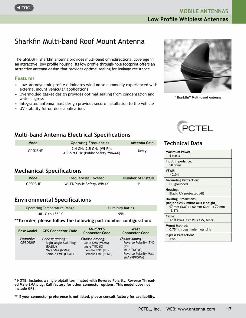
“Sharkfin” Multi-band Antenna
Technical Data Maximum Power:
5 watts
Input Impedance:50 ohms
VSWR:< 2.0:1
Grounding Protection: DC grounded
Housing:Black, UV protected ABS
Housing Dimensions (major axis x minor axis x height):
97 mm (3.8”) x 60 mm (2.4”) x 70 mm (2.8”)
Cable:12 ft Pro-Flex™ Plus 195, black
Mount Method:0.75” through hole mounting
Ingress Protection:IP56
The GPSDBHF Sharkfin antenna provides multi-band omnidirectional coverage in an attractive, low profile housing. Its low profile through-hole footprint offers an attractive antenna design that provides optimal sealing for leakage resistance.
Features• Low, aerodynamic profile eliminates wind noise commonly experienced with
external mount vehicular applications• Overmolded gasket design provides optimal sealing from condensation and
water ingress• Integrated antenna mast design provides secure installation to the vehicle• UV stability for outdoor applications
Model Frequencies Covered Number of Pigtails
GPSDBHF Wi-Fi/Public Safety/WiMAX 1*
Sharkfin Multi-band Roof Mount Antenna
Model Operating Frequencies Antenna Gain
GPSDBHF 2.4 GHz-2.5 GHz (Wi-Fi); 4.9-5.9 GHz (Public Safety/WiMAX) Unity
Operating Temperature Range Humidity Rating
-40° C to +85° C 95%
Environmental Specifications
* NOTE: Includes a single pigtail terminated with Reverse Polarity, Reverse Thread-ed Male SMA plug. Call factory for other connector options. This model does not include GPS.
** If your connector preference is not listed, please consult factory for availability.
Multi-band Antenna Electrical Specifications
Base Model GPS Connector Code AMPS/PCS Connector Code
Wi-Fi Connector Code
Example:GPSDBHF
Choose among:Right angle SMB Plug (RASBJ)Male SMA (MSMA)Female FME (FFME)
Choose among:Male SMA (MSMA)Male TNC (C)Female TNC (FC)Female FME (FFME)
Choose among: Reverse Polarity TNC (RPC) Male TNC (C) Reverse Polarity Male SMA (RPMSMA)
**To order, please follow the following part number configuration:
Mechanical Specifications

t TOCMOBILE ANTENNASCovert Antennas
18 PCTEL, Inc. WEB: www.antenna.com
APDM5920U, vertical installation. The antenna can also be
installed horizontally.
Technical Data Maximum Power:
10 watts
Polarization:Linear, horizontal or vertical
Nominal Impedance:50 ohms
VSWR:< 2.0:1
Radiator Material:ABS
Coax Cable: 10 ft RG-174/U cable (bottom fed)
ConnectorSAP (female FME)
Mounting Method:Normount® Z500 tape
Inside Window Glass Mount
This vertical or horizontal polarization antenna is designed for inside glass mount installations operating in the 800 MHz cellular, 900 MHz trunking, 1800 MHz DCS and 1900 MHz PCS bands without the need for tuning. Its tape mount easily attaches to a vehicle’s windshield or other glass surfaces making the antenna ideal for public safety or other applications requiring an unobtrusive design.
Features• Quad Band — covers 800 MHz cellular, 900 MHz trunking, 1800 MHz DCS, and
1900 MHz PCS• Low Profile — “sleek” appearance blends well with car dash interior• Efficient — simple mounting method allows installation in minutes without
holes• Economical — one antenna serves the function of four, minimizing installa-
tion and inventory requirements• Antenna can be oriented vertically or horizontally for maximum installation
flexibility
Antenna Electrical Specifications Model Frequency Range Gain Bandwidth
APDM5920U 824-960/1710-1990 MHz Unity 136/280 MHz
Normount® is a registered trademark of Norton, a Saint-Gobain Co.
Mechanical SpecificationsModel Antenna Dimensions
APDM5920U 0.5” D x 5.9” L
t TOCMOBILE ANTENNAS
Covert Antennas
PCTEL, Inc. WEB: www.antenna.com 19
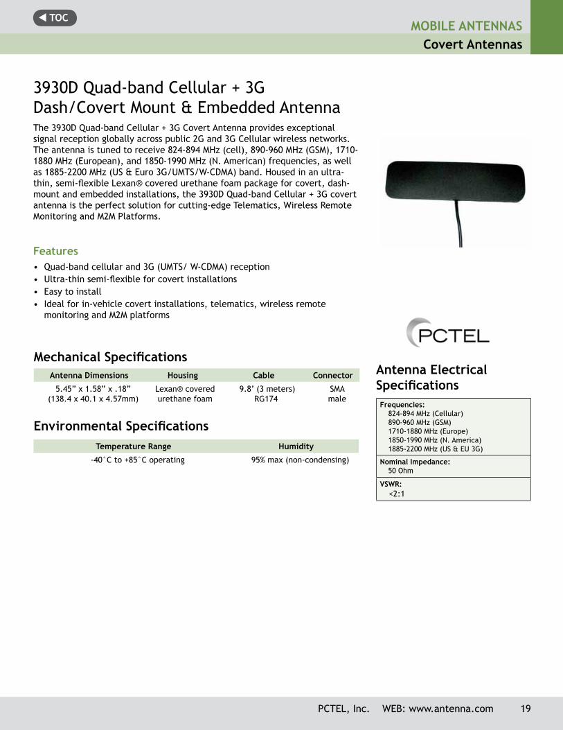
3930D Quad-band Cellular + 3GDash/Covert Mount & Embedded AntennaThe 3930D Quad-band Cellular + 3G Covert Antenna provides exceptional signal reception globally across public 2G and 3G Cellular wireless networks. The antenna is tuned to receive 824-894 MHz (cell), 890-960 MHz (GSM), 1710-1880 MHz (European), and 1850-1990 MHz (N. American) frequencies, as well as 1885-2200 MHz (US & Euro 3G/UMTS/W-CDMA) band. Housed in an ultra-thin, semi-flexible Lexan® covered urethane foam package for covert, dash-mount and embedded installations, the 3930D Quad-band Cellular + 3G covert antenna is the perfect solution for cutting-edge Telematics, Wireless Remote Monitoring and M2M Platforms.
Features• Quad-band cellular and 3G (UMTS/ W-CDMA) reception• Ultra-thin semi-flexible for covert installations• Easy to install• Ideal for in-vehicle covert installations, telematics, wireless remote
monitoring and M2M platforms
Antenna Dimensions Housing Cable Connector
5.45” x 1.58” x .18” (138.4 x 40.1 x 4.57mm)
Lexan® covered urethane foam
9.8’ (3 meters) RG174
SMAmale
Mechanical Specifications
Environmental Specifications Temperature Range Humidity
-40°C to +85°C operating 95% max (non-condensing)
Antenna Electrical SpecificationsFrequencies:
824-894 MHz (Cellular)890-960 MHz (GSM)1710-1880 MHz (Europe)1850-1990 MHz (N. America)1885-2200 MHz (US & EU 3G)
Nominal Impedance:50 Ohm
VSWR: <2:1
t TOCMOBILE ANTENNASCovert Antennas
20 PCTEL, Inc. WEB: www.antenna.com
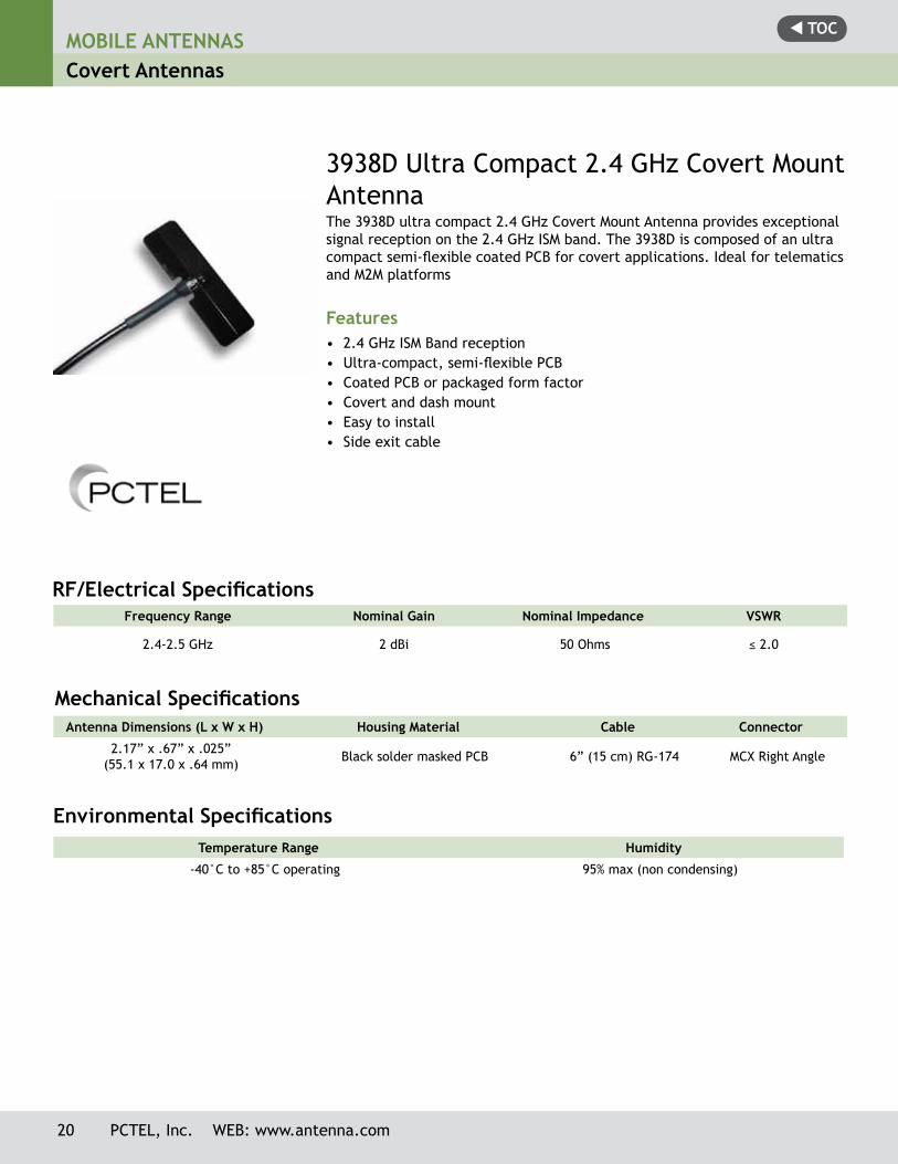
3938D Ultra Compact 2.4 GHz Covert Mount AntennaThe 3938D ultra compact 2.4 GHz Covert Mount Antenna provides exceptional signal reception on the 2.4 GHz ISM band. The 3938D is composed of an ultra compact semi-flexible coated PCB for covert applications. Ideal for telematics and M2M platforms
Features• 2.4 GHz ISM Band reception• Ultra-compact, semi-flexible PCB• Coated PCB or packaged form factor• Covert and dash mount• Easy to install• Side exit cable
Frequency Range Nominal Gain Nominal Impedance VSWR
2.4-2.5 GHz 2 dBi 50 Ohms ≤ 2.0
RF/Electrical Specifications
Environmental Specifications Temperature Range Humidity
-40°C to +85°C operating 95% max (non condensing)
Antenna Dimensions (L x W x H) Housing Material Cable Connector
2.17” x .67” x .025”(55.1 x 17.0 x .64 mm) Black solder masked PCB 6” (15 cm) RG-174 MCX Right Angle
Mechanical Specifications
t TOCMOBILE ANTENNAS
Covert Antennas
Electrical Specifications(Filter/LNA) Center Frequency:
1575.42 +/-1 MHz (GPS L1)
Amplifier Gain without Antenna Element and Cable:
26 dB +/-3
Nominal Impedance:50 ohm
Noise Figure (25°):1.8 typical
VSWR:1.5:1 typical
Voltage:3-5 V (regulated)
DC Current @ 5 Volts:20 mA Nominal< 30 mA @ -40°C to +85°C(Filter Out-Of-Band)
Filtering:Hybrid (including pre-selector)
Out-of-Band Signal Rejection:40 dB @ +/-50 MHz typical
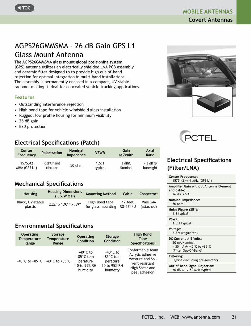
The AGPS26GMMSMA glass mount global positioning system(GPS) antenna utilizes an electrically shielded LNA PCB assemblyand ceramic filter designed to to provide high out-of-bandrejection for optimal integration in multi-band installations.The assembly is permanently encased in a compact, UV-stableradome, making it ideal for concealed vehicle tracking applications.
Features• Outstanding interference rejection• High bond tape for vehicle windshield glass installation• Rugged, low profile housing for minimum visibility• 26 dB gain• ESD protection
AGPS26GMMSMA - 26 dB Gain GPS L1 Glass Mount Antenna
Center Frequency Polarization Nominal
Impedance VSWR Gain at Zenith
AxialRatio
1575.42 MHz (GPS L1)
Right hand circular 50 ohm 1.5:1
typical3 dBiC
Nominal< 3 dB @ boresight
Electrical Specifications (Patch)
Mechanical Specifications
Housing Housing Dimensions ( L x W x D) Mounting Method Cable Connector*
Black, UV-stable plastic 2.22” x 1.97 “ x .59” High Bond tape
for glass mounting17 feet
RG-174/UMale SMA (attached)
Environmental SpecificationsOperating
Temperature Range
Storage Temperature
Range
Operating Condition
Storage Condition
High BondTape
Specifications
-40°C to +85°C -40°C to +85°C
-40°C to +85°C tem-
perature 10 to 95% RH
humidity
-40°C to +85°C tem-
perature10 to 95% RH
humidity
Conformable foamAcrylic adhesiveMoisture and Sol-
vent resistantHigh Shear and peel adhesion
PCTEL, Inc. WEB: www.antenna.com 21
t TOCMOBILE ANTENNASCovert Antennas
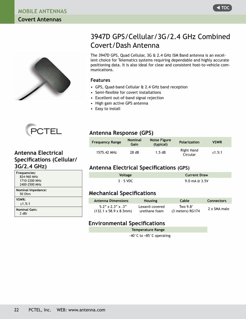
3947D GPS/Cellular/3G/2.4 GHz Combined Covert/Dash AntennaThe 3947D GPS, Quad Cellular, 3G & 2.4 GHz ISM Band antenna is an excel-lent choice for Telematics systems requiring dependable and highly accurate positioning data. It is also ideal for clear and consistent host-to-vehicle com-munications.
Features• GPS, Quad-band Cellular & 2.4 GHz band reception• Semi-flexible for covert installations• Excellent out-of-band signal rejection• High gain active GPS antenna• Easy to install
Antenna Electrical Specifications (GPS)
Antenna Dimensions Housing Cable Connectors
5.2” x 2.3” x .3” (132.1 x 58.9 x 8.5mm)
Lexan® covered urethane foam
Two 9.8’ (3 meters) RG174 2 x SMA male
Mechanical Specifications
Environmental Specifications Temperature Range
-40°C to +85°C operating
Voltage Current Draw
3 – 5 VDC 9.0 mA @ 3.5V
Frequency Range NominalGain
Noise Figure (typical) Polarization VSWR
1575.42 MHz 28 dB 1.5 dB Right Hand Circular ≤1.5:1
Antenna Response (GPS)
Antenna Electrical Specifications (Cellular/ 3G/2.4 GHz)Frequencies:
824-960 MHz1710-2200 MHz 2400-2500 MHz
Nominal Impedance:50 Ohm
VSWR: ≤1.5:1
Nominal Gain:2 dBi
22 PCTEL, Inc. WEB: www.antenna.com
t TOC
Model Frequency Range Factory Tuned Frequency Gain
MLB2700(S) 27-31 MHz Field Tunable within specified range Unity
MLBDC2700(S)** 27-31 MHz Field Tunable within specified range Unity
MLB3000(S) 30-35 MHz Field Tunable within specified range Unity
MLBDC3000(S)** 30-35 MHz Field Tunable within specified range Unity
MLBDC3400(S)** 34-37 MHz Field Tunable within specified range Unity
MLB3400(S) 34-40 MHz Field Tunable within specified range Unity
MLBDC3700(S)** 37-40 MHz Field Tunable within specified range Unity
MLB4000(S) 40-47 MHz Field Tunable within specified range Unity
MLBDC4000(S)** 40-47 MHz Field Tunable within specified range Unity
MLBDC4500(S)** 45-48 MHz Field Tunable within specified range Unity
MLBDC4700(S)** 47-50 MHz Field Tunable within specified range Unity
MLB4700(S) 47-54 MHz Field Tunable within specified range Unity
MLB6600(S) 66-132 MHz Field Tunable within specified range Unity
MOBILE ANTENNASQuarterwave Antennas
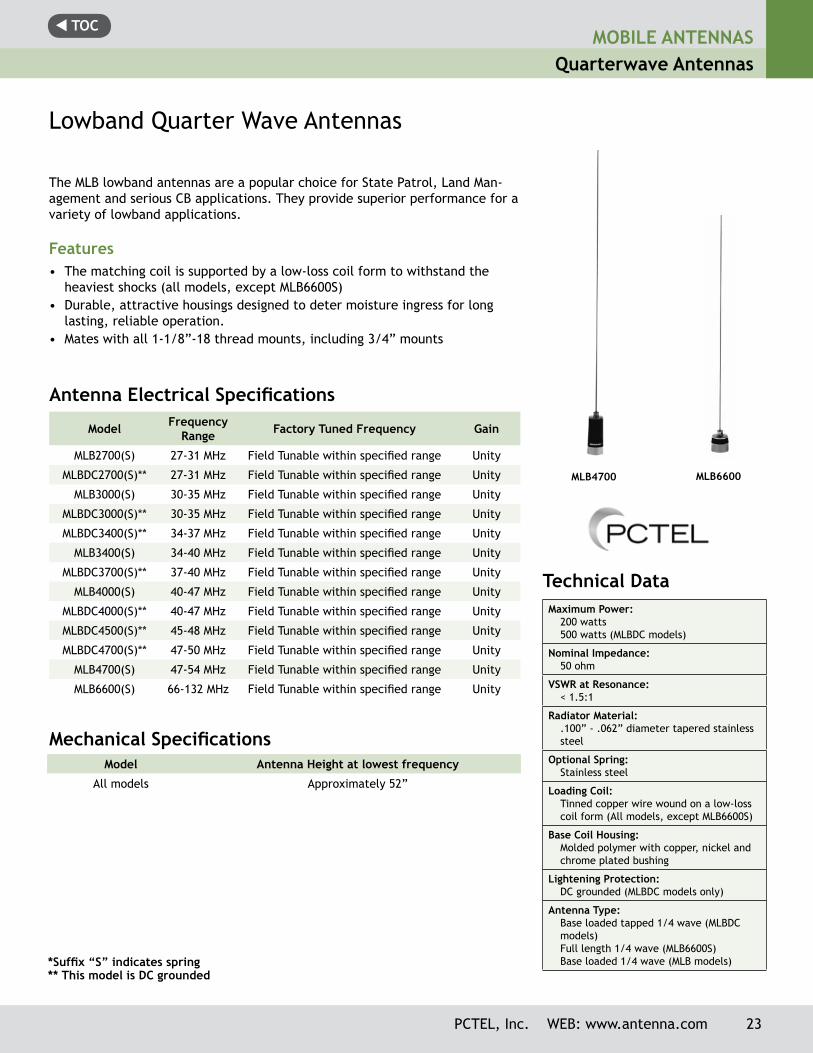
Lowband Quarter Wave Antennas
The MLB lowband antennas are a popular choice for State Patrol, Land Man-agement and serious CB applications. They provide superior performance for a variety of lowband applications.
Features• The matching coil is supported by a low-loss coil form to withstand the
heaviest shocks (all models, except MLB6600S)• Durable, attractive housings designed to deter moisture ingress for long
lasting, reliable operation.• Mates with all 1-1/8”-18 thread mounts, including 3/4” mounts
Model Antenna Height at lowest frequency
All models Approximately 52”
Antenna Electrical Specifications
*Suffix “S” indicates spring** This model is DC grounded
Mechanical Specifications
Technical Data Maximum Power:
200 watts500 watts (MLBDC models)
Nominal Impedance:50 ohm
VSWR at Resonance:< 1.5:1
Radiator Material:.100” - .062” diameter tapered stainless steel
Optional Spring:Stainless steel
Loading Coil:Tinned copper wire wound on a low-loss coil form (All models, except MLB6600S)
Base Coil Housing:Molded polymer with copper, nickel and chrome plated bushing
Lightening Protection:DC grounded (MLBDC models only)
Antenna Type:Base loaded tapped 1/4 wave (MLBDC models)Full length 1/4 wave (MLB6600S)Base loaded 1/4 wave (MLB models)
MLB4700 MLB6600
PCTEL, Inc. WEB: www.antenna.com 23
t TOCMOBILE ANTENNASQuarterwave Antennas
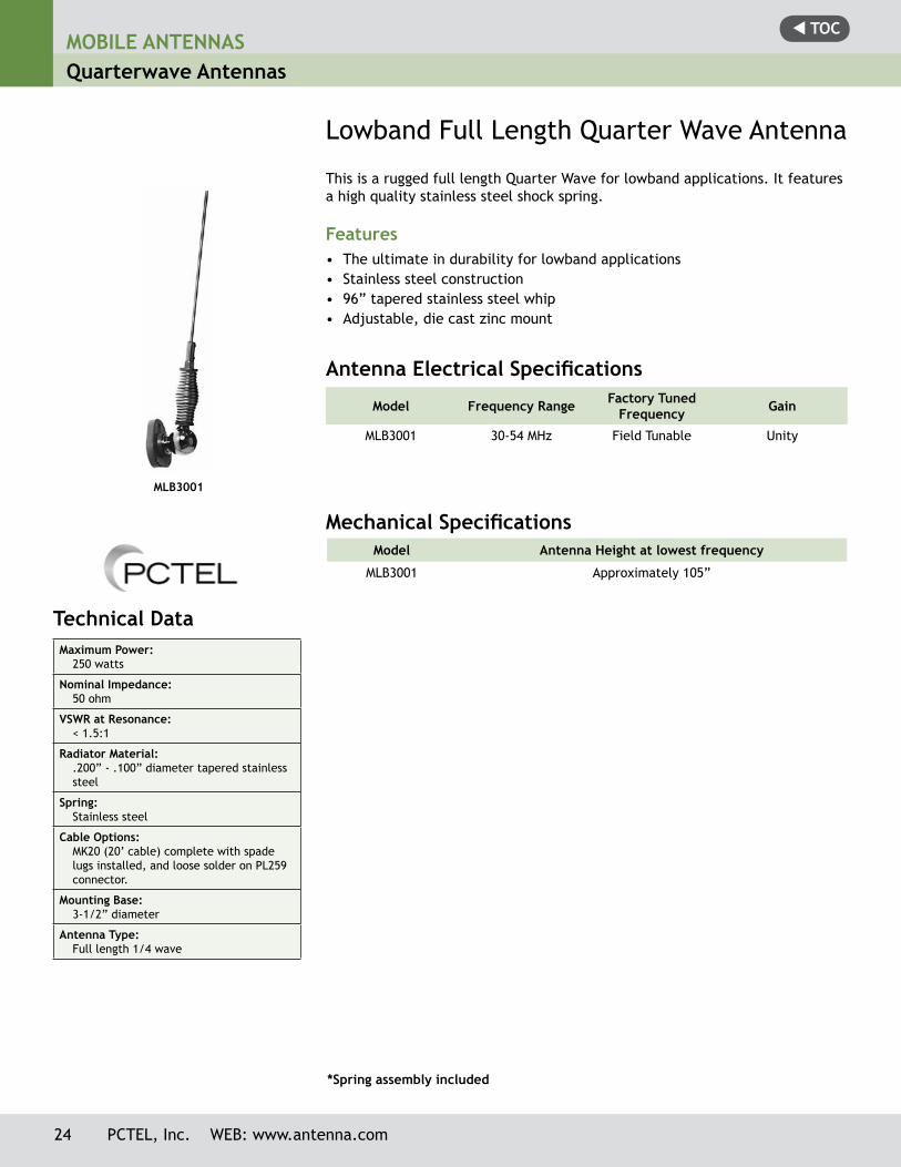
Lowband Full Length Quarter Wave Antenna
This is a rugged full length Quarter Wave for lowband applications. It features a high quality stainless steel shock spring.
Features• The ultimate in durability for lowband applications• Stainless steel construction• 96” tapered stainless steel whip• Adjustable, die cast zinc mount
Model Frequency Range Factory Tuned Frequency Gain
MLB3001 30-54 MHz Field Tunable Unity
Antenna Electrical Specifications
*Spring assembly included
Mechanical SpecificationsModel Antenna Height at lowest frequency
MLB3001 Approximately 105”
MLB3001
Technical Data Maximum Power:
250 watts
Nominal Impedance:50 ohm
VSWR at Resonance:< 1.5:1
Radiator Material:.200” - .100” diameter tapered stainless steel
Spring:Stainless steel
Cable Options: MK20 (20’ cable) complete with spade lugs installed, and loose solder on PL259 connector.
Mounting Base:3-1/2” diameter
Antenna Type:Full length 1/4 wave
24 PCTEL, Inc. WEB: www.antenna.com
t TOC
PCTEL, Inc. WEB: www.antenna.com 25
MOBILE ANTENNASQuarterwave Antennas
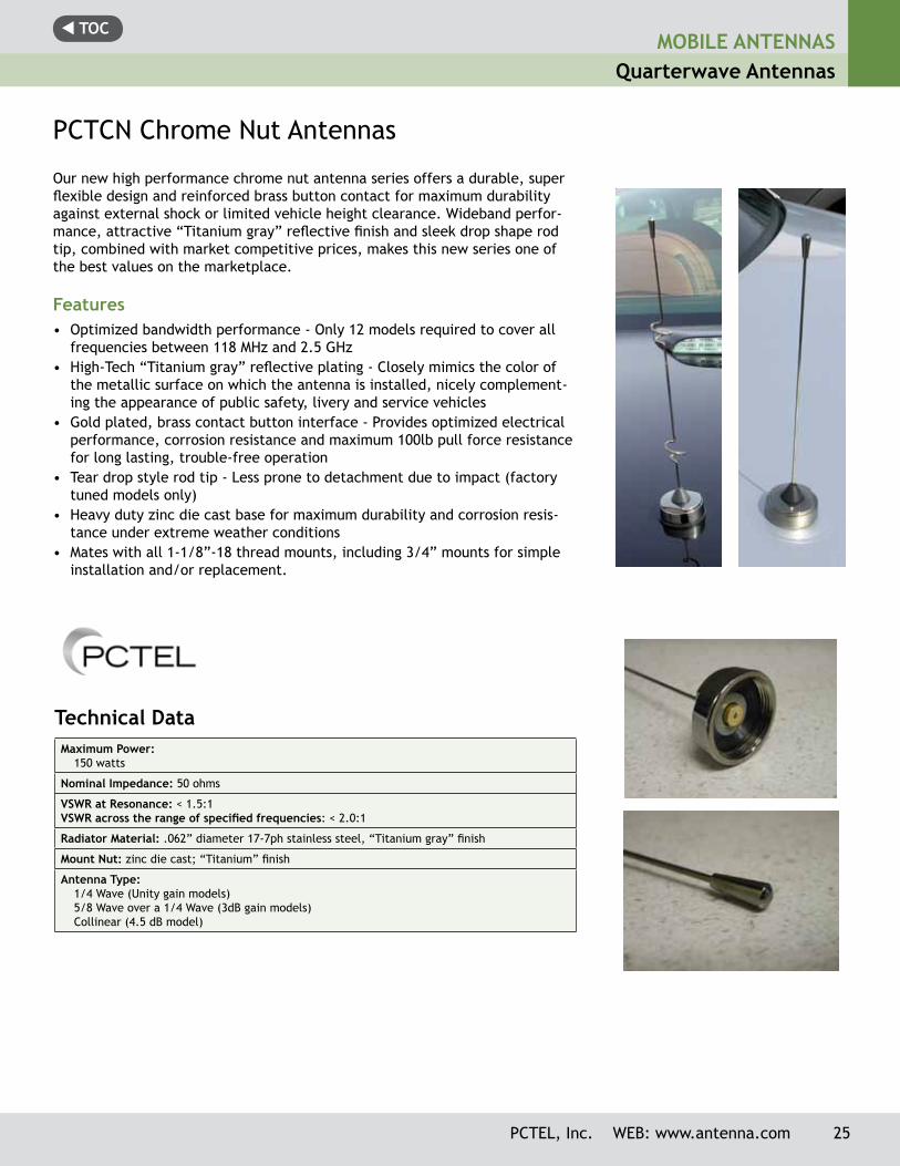
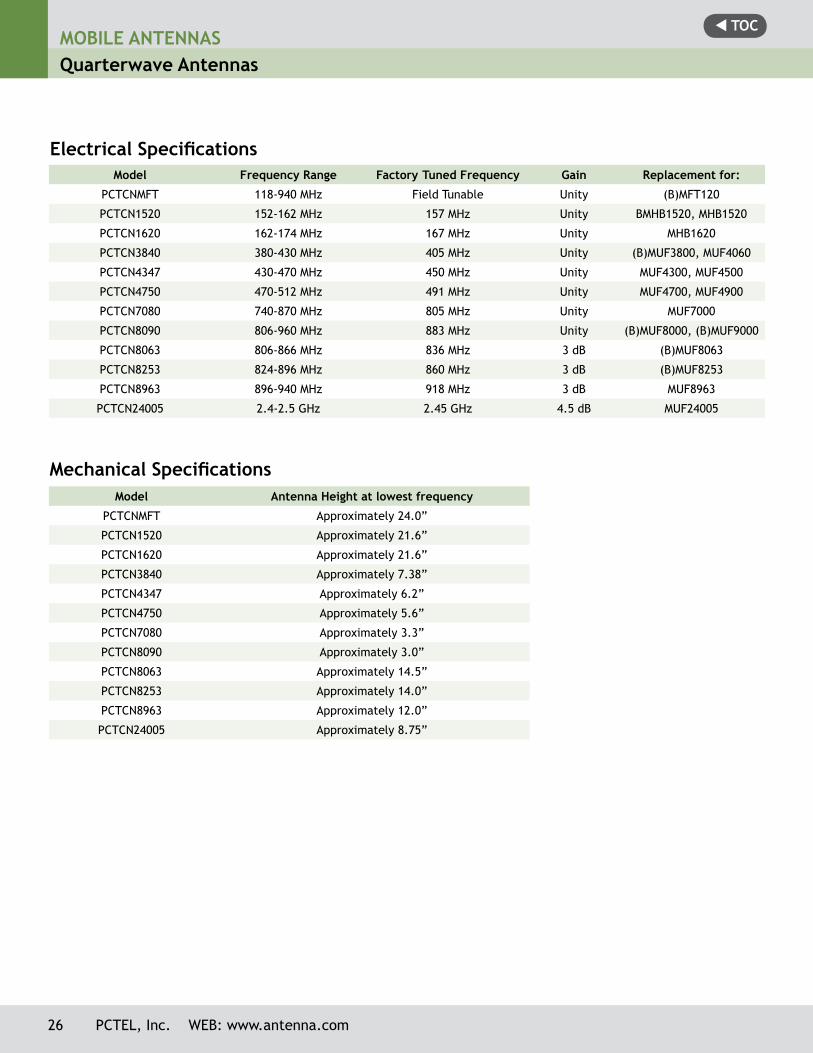
PCTCN Chrome Nut Antennas
Our new high performance chrome nut antenna series offers a durable, super flexible design and reinforced brass button contact for maximum durability against external shock or limited vehicle height clearance. Wideband perfor-mance, attractive “Titanium gray” reflective finish and sleek drop shape rod tip, combined with market competitive prices, makes this new series one of the best values on the marketplace.
Features• Optimized bandwidth performance - Only 12 models required to cover all
frequencies between 118 MHz and 2.5 GHz• High-Tech “Titanium gray” reflective plating - Closely mimics the color of
the metallic surface on which the antenna is installed, nicely complement-ing the appearance of public safety, livery and service vehicles
• Gold plated, brass contact button interface - Provides optimized electrical performance, corrosion resistance and maximum 100lb pull force resistance for long lasting, trouble-free operation
• Tear drop style rod tip - Less prone to detachment due to impact (factory tuned models only)
• Heavy duty zinc die cast base for maximum durability and corrosion resis-tance under extreme weather conditions
• Mates with all 1-1/8”-18 thread mounts, including 3/4” mounts for simple installation and/or replacement.
Technical Data Maximum Power:
150 watts
Nominal Impedance: 50 ohms
VSWR at Resonance: < 1.5:1VSWR across the range of specified frequencies: < 2.0:1
Radiator Material: .062” diameter 17-7ph stainless steel, “Titanium gray” finish
Mount Nut: zinc die cast; “Titanium” finish
Antenna Type:1/4 Wave (Unity gain models)5/8 Wave over a 1/4 Wave (3dB gain models)Collinear (4.5 dB model)
t TOCMOBILE ANTENNASQuarterwave Antennas
26 PCTEL, Inc. WEB: www.antenna.com
Model Frequency Range Factory Tuned Frequency Gain Replacement for:
PCTCNMFT 118-940 MHz Field Tunable Unity (B)MFT120
PCTCN1520 152-162 MHz 157 MHz Unity BMHB1520, MHB1520
PCTCN1620 162-174 MHz 167 MHz Unity MHB1620
PCTCN3840 380-430 MHz 405 MHz Unity (B)MUF3800, MUF4060
PCTCN4347 430-470 MHz 450 MHz Unity MUF4300, MUF4500
PCTCN4750 470-512 MHz 491 MHz Unity MUF4700, MUF4900
PCTCN7080 740-870 MHz 805 MHz Unity MUF7000
PCTCN8090 806-960 MHz 883 MHz Unity (B)MUF8000, (B)MUF9000
PCTCN8063 806-866 MHz 836 MHz 3 dB (B)MUF8063
PCTCN8253 824-896 MHz 860 MHz 3 dB (B)MUF8253
PCTCN8963 896-940 MHz 918 MHz 3 dB MUF8963
PCTCN24005 2.4-2.5 GHz 2.45 GHz 4.5 dB MUF24005
Electrical Specifications
Model Antenna Height at lowest frequency
PCTCNMFT Approximately 24.0”
PCTCN1520 Approximately 21.6”
PCTCN1620 Approximately 21.6”
PCTCN3840 Approximately 7.38”
PCTCN4347 Approximately 6.2”
PCTCN4750 Approximately 5.6”
PCTCN7080 Approximately 3.3”
PCTCN8090 Approximately 3.0”
PCTCN8063 Approximately 14.5”
PCTCN8253 Approximately 14.0”
PCTCN8963 Approximately 12.0”
PCTCN24005 Approximately 8.75”
Mechanical Specifications
t TOC
PCTEL, Inc. WEB: www.antenna.com 27
MOBILE ANTENNASMolded Base Antennas
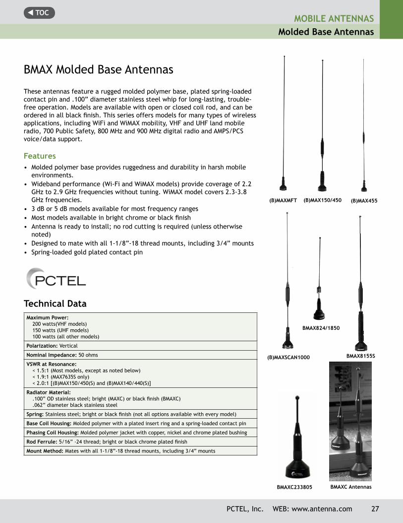
BMAX Molded Base Antennas
These antennas feature a rugged molded polymer base, plated spring-loaded contact pin and .100” diameter stainless steel whip for long-lasting, trouble-free operation. Models are available with open or closed coil rod, and can be ordered in all black finish. This series offers models for many types of wireless applications, including WiFi and WiMAX mobility, VHF and UHF land mobile radio, 700 Public Safety, 800 MHz and 900 MHz digital radio and AMPS/PCS voice/data support.
Features• Molded polymer base provides ruggedness and durability in harsh mobile
environments. • Wideband performance (Wi-Fi and WiMAX models) provide coverage of 2.2
GHz to 2.9 GHz frequencies without tuning. WiMAX model covers 2.3-3.8 GHz frequencies.
• 3 dB or 5 dB models available for most frequency ranges• Most models available in bright chrome or black finish• Antenna is ready to install; no rod cutting is required (unless otherwise
noted)• Designed to mate with all 1-1/8”-18 thread mounts, including 3/4” mounts• Spring-loaded gold plated contact pin
Technical Data Maximum Power:
200 watts(VHF models)150 watts (UHF models)100 watts (all other models)
Polarization: Vertical
Nominal Impedance: 50 ohms
VSWR at Resonance: < 1.5:1 (Most models, except as noted below)< 1.9:1 (MAX7635S only)< 2.0:1 [(B)MAX150/450(S) and (B)MAX140/440(S)]
Radiator Material:.100” OD stainless steel; bright (MAXC) or black finish (BMAXC).062” diameter black stainless steel
Spring: Stainless steel; bright or black finish (not all options available with every model)
Base Coil Housing: Molded polymer with a plated insert ring and a spring-loaded contact pin
Phasing Coil Housing: Molded polymer jacket with copper, nickel and chrome plated bushing
Rod Ferrule: 5/16” -24 thread; bright or black chrome plated finish
Mount Method: Mates with all 1-1/8”-18 thread mounts, including 3/4” mounts
BMAXC Antennas
BMAX824/1850
(B)MAX150/450 (B)MAX455
BMAX8155S(B)MAXSCAN1000
(B)MAXMFT
BMAXC233805
t TOCMOBILE ANTENNASMolded Base Antennas
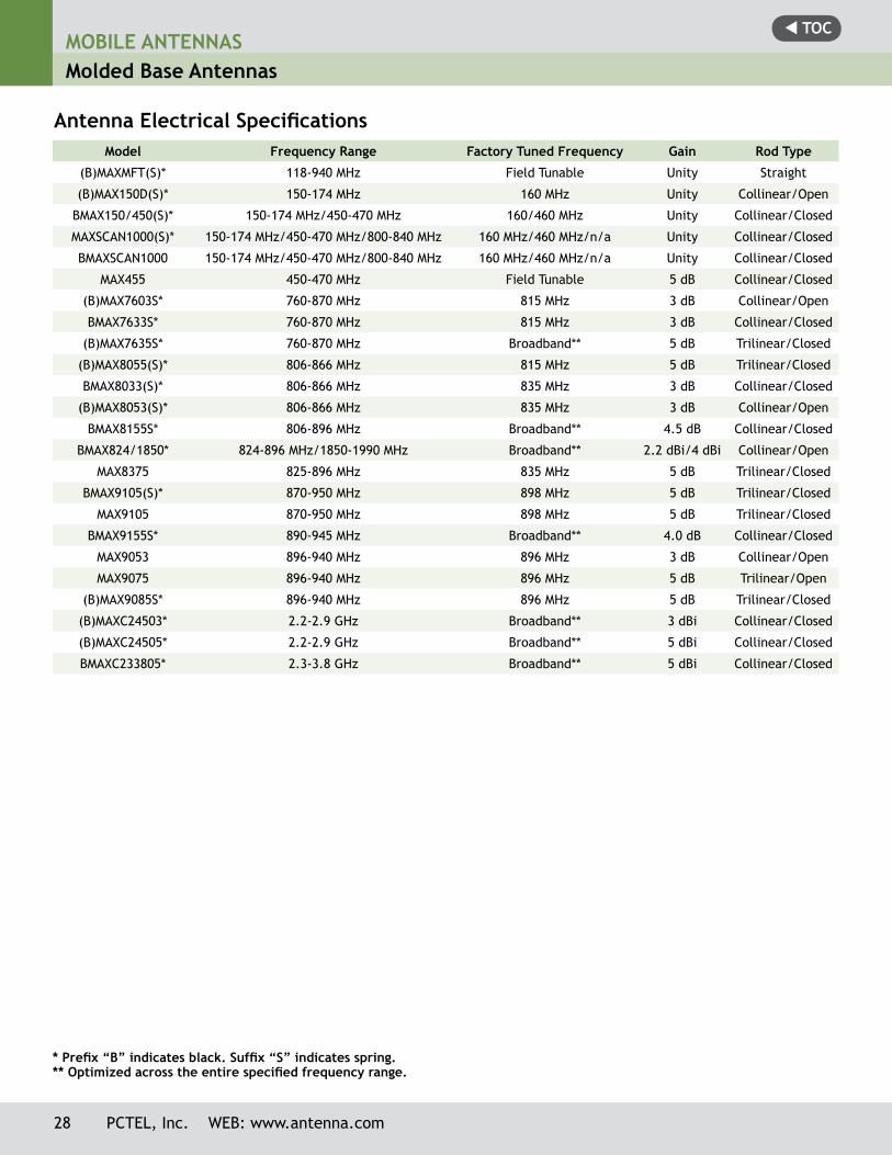
Antenna Electrical Specifications
* Prefix “B” indicates black. Suffix “S” indicates spring. ** Optimized across the entire specified frequency range.
Model Frequency Range Factory Tuned Frequency Gain Rod Type
(B)MAXMFT(S)* 118-940 MHz Field Tunable Unity Straight
(B)MAX150D(S)* 150-174 MHz 160 MHz Unity Collinear/Open
BMAX150/450(S)* 150-174 MHz/450-470 MHz 160/460 MHz Unity Collinear/Closed
MAXSCAN1000(S)* 150-174 MHz/450-470 MHz/800-840 MHz 160 MHz/460 MHz/n/a Unity Collinear/Closed
BMAXSCAN1000 150-174 MHz/450-470 MHz/800-840 MHz 160 MHz/460 MHz/n/a Unity Collinear/Closed
MAX455 450-470 MHz Field Tunable 5 dB Collinear/Closed
(B)MAX7603S* 760-870 MHz 815 MHz 3 dB Collinear/Open
BMAX7633S* 760-870 MHz 815 MHz 3 dB Collinear/Closed
(B)MAX7635S* 760-870 MHz Broadband** 5 dB Trilinear/Closed
(B)MAX8055(S)* 806-866 MHz 815 MHz 5 dB Trilinear/Closed
BMAX8033(S)* 806-866 MHz 835 MHz 3 dB Collinear/Closed
(B)MAX8053(S)* 806-866 MHz 835 MHz 3 dB Collinear/Open
BMAX8155S* 806-896 MHz Broadband** 4.5 dB Collinear/Closed
BMAX824/1850* 824-896 MHz/1850-1990 MHz Broadband** 2.2 dBi/4 dBi Collinear/Open
MAX8375 825-896 MHz 835 MHz 5 dB Trilinear/Closed
BMAX9105(S)* 870-950 MHz 898 MHz 5 dB Trilinear/Closed
MAX9105 870-950 MHz 898 MHz 5 dB Trilinear/Closed
BMAX9155S* 890-945 MHz Broadband** 4.0 dB Collinear/Closed
MAX9053 896-940 MHz 896 MHz 3 dB Collinear/Open
MAX9075 896-940 MHz 896 MHz 5 dB Trilinear/Open
(B)MAX9085S* 896-940 MHz 896 MHz 5 dB Trilinear/Closed
(B)MAXC24503* 2.2-2.9 GHz Broadband** 3 dBi Collinear/Closed
(B)MAXC24505* 2.2-2.9 GHz Broadband** 5 dBi Collinear/Closed
BMAXC233805* 2.3-3.8 GHz Broadband** 5 dBi Collinear/Closed
28 PCTEL, Inc. WEB: www.antenna.com
t TOCMOBILE ANTENNAS
Molded Base Antennas
PCTEL, Inc. WEB: www.antenna.com 29
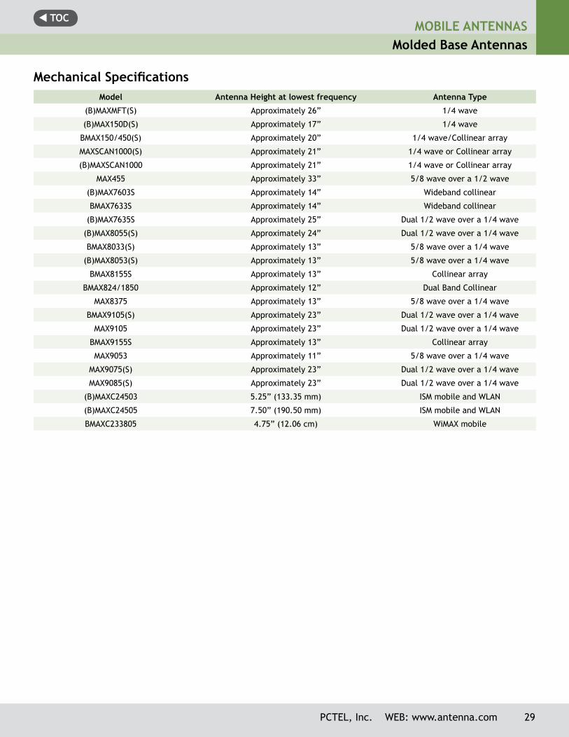
Mechanical SpecificationsModel Antenna Height at lowest frequency Antenna Type
(B)MAXMFT(S) Approximately 26” 1/4 wave
(B)MAX150D(S) Approximately 17” 1/4 wave
BMAX150/450(S) Approximately 20” 1/4 wave/Collinear array
MAXSCAN1000(S) Approximately 21” 1/4 wave or Collinear array
(B)MAXSCAN1000 Approximately 21” 1/4 wave or Collinear array
MAX455 Approximately 33” 5/8 wave over a 1/2 wave
(B)MAX7603S Approximately 14” Wideband collinear
BMAX7633S Approximately 14” Wideband collinear
(B)MAX7635S Approximately 25” Dual 1/2 wave over a 1/4 wave
(B)MAX8055(S) Approximately 24” Dual 1/2 wave over a 1/4 wave
BMAX8033(S) Approximately 13” 5/8 wave over a 1/4 wave
(B)MAX8053(S) Approximately 13” 5/8 wave over a 1/4 wave
BMAX8155S Approximately 13” Collinear array
BMAX824/1850 Approximately 12” Dual Band Collinear
MAX8375 Approximately 13” 5/8 wave over a 1/4 wave
BMAX9105(S) Approximately 23” Dual 1/2 wave over a 1/4 wave
MAX9105 Approximately 23” Dual 1/2 wave over a 1/4 wave
BMAX9155S Approximately 13” Collinear array
MAX9053 Approximately 11” 5/8 wave over a 1/4 wave
MAX9075(S) Approximately 23” Dual 1/2 wave over a 1/4 wave
MAX9085(S) Approximately 23” Dual 1/2 wave over a 1/4 wave
(B)MAXC24503 5.25” (133.35 mm) ISM mobile and WLAN
(B)MAXC24505 7.50” (190.50 mm) ISM mobile and WLAN
BMAXC233805 4.75” (12.06 cm) WiMAX mobile
t TOCMOBILE ANTENNASMolded Base Antennas
30 PCTEL, Inc. WEB: www.antenna.com
*Prefix “B” indicates black. Suffix “S” indicates spring.
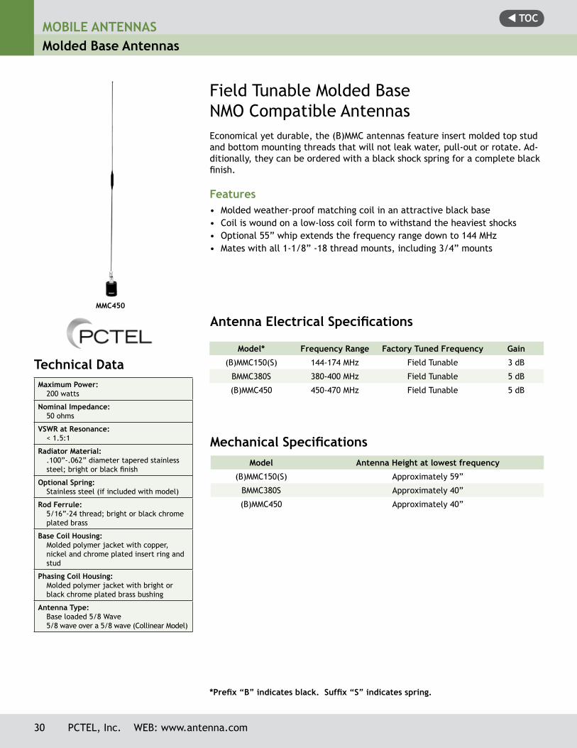
Field Tunable Molded BaseNMO Compatible AntennasEconomical yet durable, the (B)MMC antennas feature insert molded top stud and bottom mounting threads that will not leak water, pull-out or rotate. Ad-ditionally, they can be ordered with a black shock spring for a com plete black finish.
Features• Molded weather-proof matching coil in an attractive black base• Coil is wound on a low-loss coil form to withstand the heaviest shocks• Optional 55” whip extends the frequency range down to 144 MHz• Mates with all 1-1/8” -18 thread mounts, including 3/4” mounts
Antenna Electrical Specifications
Model* Frequency Range Factory Tuned Frequency Gain
(B)MMC150(S) 144-174 MHz Field Tunable 3 dB
BMMC380S 380-400 MHz Field Tunable 5 dB
(B)MMC450 450-470 MHz Field Tunable 5 dB
Mechanical SpecificationsModel Antenna Height at lowest frequency
(B)MMC150(S) Approximately 59”
BMMC380S Approximately 40”
(B)MMC450 Approximately 40”
MMC450
Technical Data Maximum Power:
200 watts
Nominal Impedance:50 ohms
VSWR at Resonance:< 1.5:1
Radiator Material:.100”-.062” diameter tapered stainless steel; bright or black finish
Optional Spring:Stainless steel (if included with model)
Rod Ferrule: 5/16”-24 thread; bright or black chrome plated brass
Base Coil Housing:Molded polymer jacket with copper, nickel and chrome plated insert ring and stud
Phasing Coil Housing:Molded polymer jacket with bright or black chrome plated brass bushing
Antenna Type:Base loaded 5/8 Wave5/8 wave over a 5/8 wave (Collinear Model)
t TOCMOBILE ANTENNAS
Molded Base Antennas
PCTEL, Inc. WEB: www.antenna.com 31
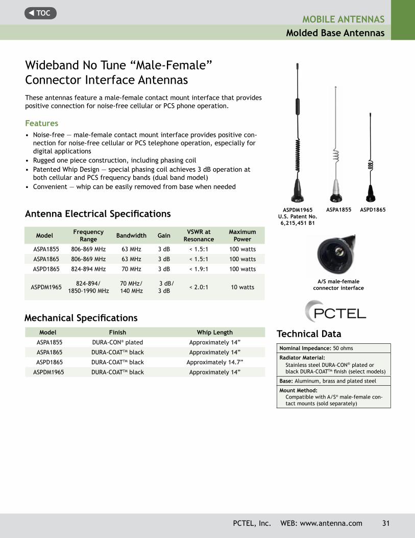
Wideband No Tune “Male-Female” Connector Interface AntennasThese antennas feature a male-female contact mount interface that provides positive connection for noise-free cellular or PCS phone operation.
Features• Noise-free — male-female contact mount interface provides positive con-
nection for noise-free cellular or PCS telephone operation, especially for digital applications
• Rugged one piece construction, including phasing coil• Patented Whip Design — special phasing coil achieves 3 dB operation at
both cellular and PCS frequency bands (dual band model)• Convenient — whip can be easily removed from base when needed
Mechanical SpecificationsModel Finish Whip Length
ASPA1855 DURA-CON® plated Approximately 14”
ASPA1865 DURA-COATTM black Approximately 14”
ASPD1865 DURA-COATTM black Approximately 14.7”
ASPDM1965 DURA-COATTM black Approximately 14”
Antenna Electrical Specifications
Model Frequency Range Bandwidth Gain VSWR at
ResonanceMaximum
Power
ASPA1855 806-869 MHz 63 MHz 3 dB < 1.5:1 100 watts
ASPA1865 806-869 MHz 63 MHz 3 dB < 1.5:1 100 watts
ASPD1865 824-894 MHz 70 MHz 3 dB < 1.9:1 100 watts
ASPDM1965 824-894/1850-1990 MHz
70 MHz/140 MHz
3 dB/3 dB < 2.0:1 10 watts
ASPD1865
ASPA1855ASPDM1965U.S. Patent No. 6,215,451 B1
Technical Data Nominal Impedance: 50 ohms
Radiator Material:Stainless steel DURA-CON® plated or black DURA-COATTM finish (select models)
Base: Aluminum, brass and plated steel
Mount Method:Compatible with A/S® male-female con-tact mounts (sold separately)
ASPD1865
A/S male-female connector interface
t TOC
32 PCTEL, Inc. WEB: www.antenna.com
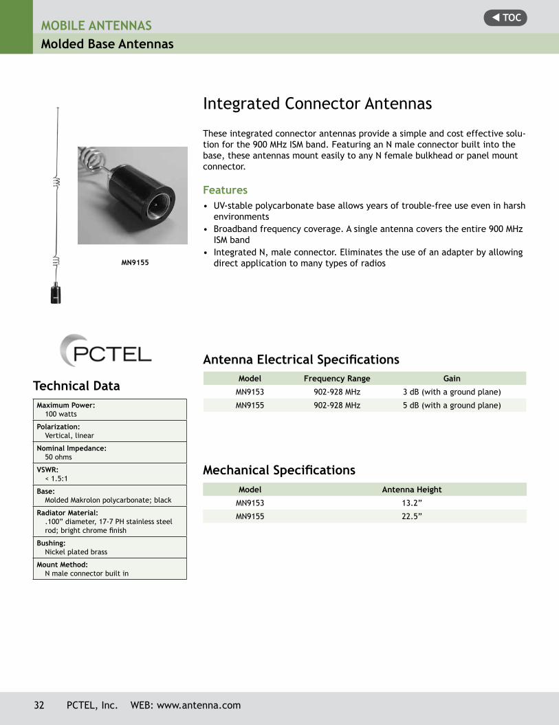
Integrated Connector Antennas
Model Frequency Range Gain
MN9153 902-928 MHz 3 dB (with a ground plane)
MN9155 902-928 MHz 5 dB (with a ground plane)
Antenna Electrical Specifications
Mechanical SpecificationsModel Antenna Height
MN9153 13.2”
MN9155 22.5”
These integrated connector antennas provide a simple and cost effective solu-tion for the 900 MHz ISM band. Featuring an N male connector built into the base, these antennas mount easily to any N female bulkhead or panel mount connector.
Features• UV-stable polycarbonate base allows years of trouble-free use even in harsh
environments• Broadband frequency coverage. A single antenna covers the entire 900 MHz
ISM band• Integrated N, male connector. Eliminates the use of an adapter by allowing
direct application to many types of radios
Technical Data Maximum Power:
100 watts
Polarization:Vertical, linear
Nominal Impedance:50 ohms
VSWR:< 1.5:1
Base:Molded Makrolon polycarbonate; black
Radiator Material:.100” diameter, 17-7 PH stainless steel rod; bright chrome finish
Bushing:Nickel plated brass
Mount Method:N male connector built in
MN9155
MOBILE ANTENNASMolded Base Antennas
t TOC
PCTEL, Inc. WEB: www.antenna.com 33
MOBILE ANTENNASMolded Base Antennas with Rubber “Elastomer” Spring
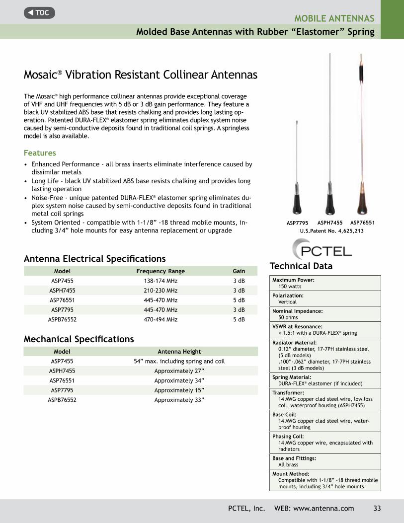
ASPH7455 ASP76551ASP7795U.S.Patent No. 4,625,213
Technical Data Maximum Power:
150 watts
Polarization:Vertical
Nominal Impedance:50 ohms
VSWR at Resonance:< 1.5:1 with a DURA-FLEX® spring
Radiator Material:0.12” diameter, 17-7PH stainless steel (5 dB models).100”-.062” diameter, 17-7PH stainless steel (3 dB models)
Spring Material:DURA-FLEX® elastomer (if included)
Transformer:14 AWG copper clad steel wire, low loss coil, waterproof housing (ASPH7455)
Base Coil:14 AWG copper clad steel wire, water-proof housing
Phasing Coil:14 AWG copper wire, encapsulated with radiators
Base and Fittings:All brass
Mount Method:Compatible with 1-1/8” -18 thread mobile mounts, including 3/4” hole mounts
Mosaic® Vibration Resistant Collinear Antennas
The Mosaic® high performance collinear antennas provide exceptional coverage of VHF and UHF frequencies with 5 dB or 3 dB gain performance. They feature a black UV stabilized ABS base that resists chalking and provides long lasting op-eration. Patented DURA-FLEX® elastomer spring eliminates duplex system noise caused by semi-conductive deposits found in traditional coil springs. A springless model is also available.
Features• Enhanced Performance - all brass inserts eliminate interference caused by
dissimilar metals• Long Life - black UV stabilized ABS base resists chalking and provides long
lasting operation• Noise-Free - unique patented DURA-FLEX® elastomer spring eliminates du-
plex system noise caused by semi-conductive deposits found in traditional metal coil springs
• System Oriented - compatible with 1-1/8” -18 thread mobile mounts, in-cluding 3/4” hole mounts for easy antenna replacement or upgrade
Mechanical SpecificationsModel Antenna Height
ASP7455 54” max. including spring and coil
ASPH7455 Approximately 27”
ASP76551 Approximately 34”
ASP7795 Approximately 15”
ASPB76552 Approximately 33”
Antenna Electrical Specifications Model Frequency Range Gain
ASP7455 138-174 MHz 3 dB
ASPH7455 210-230 MHz 3 dB
ASP76551 445-470 MHz 5 dB
ASP7795 445-470 MHz 3 dB
ASPB76552 470-494 MHz 5 dB
t TOC
Technical Data Maximum Power:
50 watts (MEFC24005 only) 10 watts (all other models)
Polarization:Vertical
Nominal Impedance:50 Ohm
VSWR:<1.5:1
Return Loss:< 10 dB
Radome Material:UV stable ABS
Radiator Material:.100” OD stainless steel; bright (MEFC) or black finish (BMEFC)
Mount Method:Compatible with most 1-1/8”-18 thread mounts. See recommended mount op-tions for each model.*
MOBILE ANTENNASElevated Feed Point Antennas
* Models (B)MEFC49005HF and (B)MEFC58005HF must be ordered with recom-mended mount(s) listed above. Consult factory for other connector options of-fered with these mounts.
Mounting Options
Antenna Model Recommended Mount Model(s) Options
(B)MEFC24005 MLFML195CLow frequency 3/4” hole permanent mount, 17 ft. Pro-FlexTM Plus 195, TNC male standard
(B)MEFC24005 GMLFML195C Low frequency magnetic mount, 12 ft. Pro-FlexTM Plus 195, TNC male standard
(B)MEFC24005 MVP Permanent Mount, 5/8” hole; 1-1/8”-18 thread; thick plate mount
(B)MEFC49005HF(B)MEFC58005HFMEFC2427HF
MHFML195C* Permanent Mount, 17 ft. Pro-FlexTM Plus 195, TNC male loose
(B)MEFC49005HF(B)MEFC58005HF MEFC2427HF
GMHFML195C* Magnetic Mount, 12 ft. Pro-FlexTM Plus 195, TNC male attached
(B)MEFC49005HF(B)MEFC58005HFMEFC2427HF
MVPHF Permanent Mount, 5/8” hole; 1-1/8”-18 thread; thick plate mount
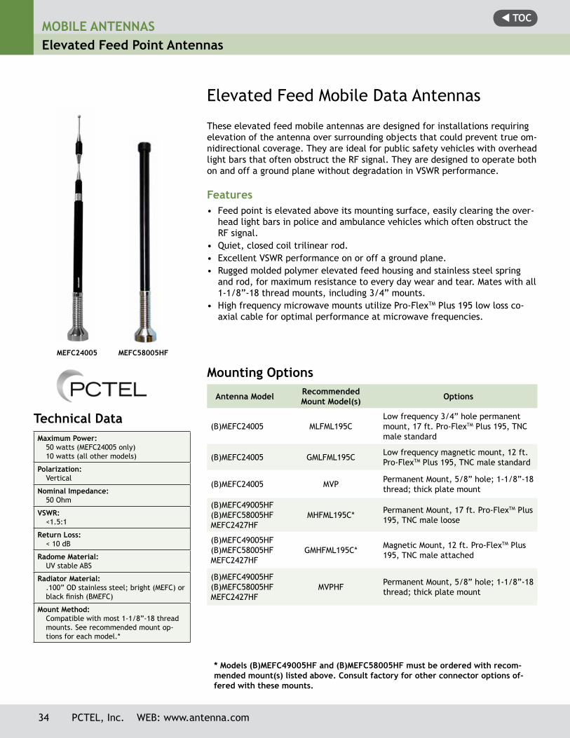
Elevated Feed Mobile Data Antennas
These elevated feed mobile antennas are designed for installations requiring elevation of the antenna over surrounding objects that could prevent true om-nidirectional coverage. They are ideal for public safety vehicles with overhead light bars that often obstruct the RF signal. They are designed to operate both on and off a ground plane without degradation in VSWR performance.
Features• Feed point is elevated above its mounting surface, easily clearing the over-
head light bars in police and ambulance vehicles which often obstruct the RF signal.
• Quiet, closed coil trilinear rod.• Excellent VSWR performance on or off a ground plane.• Rugged molded polymer elevated feed housing and stainless steel spring
and rod, for maximum resistance to every day wear and tear. Mates with all 1-1/8”-18 thread mounts, including 3/4” mounts.
• High frequency microwave mounts utilize Pro-FlexTM Plus 195 low loss co-axial cable for optimal performance at microwave frequencies.
34 PCTEL, Inc. WEB: www.antenna.com
MEFC24005 MEFC58005HF
t TOCMOBILE ANTENNAS
Elevated Feed Point Antennas
PCTEL, Inc. WEB: www.antenna.com 35
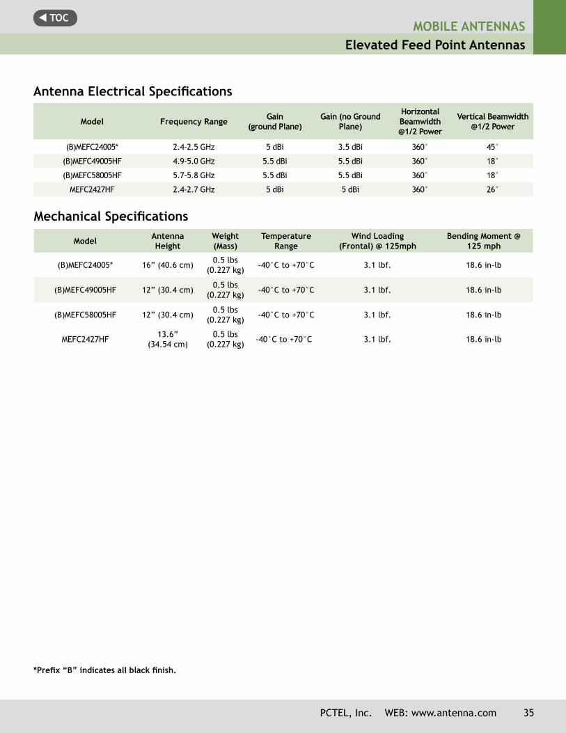
Antenna Electrical Specifications
Model Frequency Range Gain(ground Plane)
Gain (no Ground Plane)
Horizontal Beamwidth@1/2 Power
Vertical Beamwidth@1/2 Power
(B)MEFC24005* 2.4-2.5 GHz 5 dBi 3.5 dBi 360° 45°
(B)MEFC49005HF 4.9-5.0 GHz 5.5 dBi 5.5 dBi 360° 18°
(B)MEFC58005HF 5.7-5.8 GHz 5.5 dBi 5.5 dBi 360° 18°
MEFC2427HF 2.4-2.7 GHz 5 dBi 5 dBi 360° 26°
Mechanical Specifications
Model Antenna Height
Weight(Mass)
Temperature Range
Wind Loading (Frontal) @ 125mph
Bending Moment @ 125 mph
(B)MEFC24005* 16” (40.6 cm) 0.5 lbs (0.227 kg) -40°C to +70°C 3.1 lbf. 18.6 in-lb
(B)MEFC49005HF 12” (30.4 cm) 0.5 lbs (0.227 kg) -40°C to +70°C 3.1 lbf. 18.6 in-lb
(B)MEFC58005HF 12” (30.4 cm) 0.5 lbs (0.227 kg) -40°C to +70°C 3.1 lbf. 18.6 in-lb
MEFC2427HF 13.6” (34.54 cm)
0.5 lbs (0.227 kg) -40°C to +70°C 3.1 lbf. 18.6 in-lb
*Prefix “B” indicates all black finish.
t TOCMOBILE ANTENNASElevated Feed Point Antennas
Technical Data Maximum Power:
125 watts
Polarization:Vertical
Nominal Impedance:50 ohms
VSWR at Resonance:< 1.5:1
Radiator Material:.100”-.062” diameter stainless steel;bright or black finish
Spring:Stainless steel; bright or black finish
Phasing Coil Housing:Molded polymer jacket with copper, nickel and chrome plated brass bushing
Rod Ferrule:5/16”-24 thread; bright or black chromeplated brass
Body:UV stable ABS
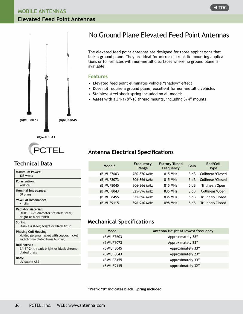
(B)MUF8043
(B)MUF8073 (B)MUF8045
No Ground Plane Elevated Feed Point Antennas
The elevated feed point antennas are designed for those applications that lack a ground plane. They are ideal for mirror or trunk lid mounting applica-tions or for vehicles with non-metallic surfaces where no ground plane is available.
Features• Elevated feed point eliminates vehicle “shadow” effect• Does not require a ground plane; excellent for non-metallic vehicles• Stainless steel shock spring included on all models• Mates with all 1-1/8”-18 thread mounts, including 3/4” mounts
Model* Frequency Range
Factory Tuned Frequency Gain Rod/Coil
Type
(B)MUF7603 760-870 MHz 815 MHz 3 dB Collinear/Closed
(B)MUF8073 806-866 MHz 815 MHz 3 dB Collinear/Closed
(B)MUF8045 806-866 MHz 815 MHz 5 dB Trilinear/Open
(B)MUF8043 825-896 MHz 835 MHz 3 dB Collinear/Open
(B)MUF8455 825-896 MHz 835 MHz 5 dB Trilinear/Closed
(B)MUF9115 896-940 MHz 898 MHz 5 dB Trilinear/Closed
*Prefix “B” indicates black. Spring included.
Antenna Electrical Specifications
Model Antenna Height at lowest frequency
(B)MUF7603 Approximately 38”
(B)MUF8073 Approximately 23”
(B)MUF8045 Approximately 33”
(B)MUF8043 Approximately 23”
(B)MUF8455 Approximately 33”
(B)MUF9115 Approximately 32”
Mechanical Specifications
36 PCTEL, Inc. WEB: www.antenna.com
t TOCMOBILE ANTENNAS
Elevated Feed Point Antennas
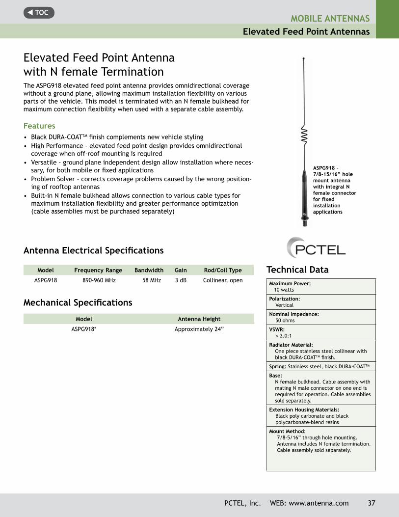
ASPG918 -7/8-15/16” hole mount antenna with integral N female connectorfor fixed installation applications
Technical Data Maximum Power: 10 watts
Polarization: Vertical
Nominal Impedance: 50 ohms
VSWR: < 2.0:1
Radiator Material:One piece stainless steel collinear with black DURA-COATTM finish.
Spring: Stainless steel, black DURA-COATTM
Base: N female bulkhead. Cable assembly with mating N male connector on one end is required for operation. Cable assemblies sold separately.
Extension Housing Materials: Black poly carbonate and black polycarbonate-blend resins
Mount Method: 7/8-5/16” through hole mounting.
Antenna includes N female termination. Cable assembly sold separately.
Elevated Feed Point Antenna with N female TerminationThe ASPG918 elevated feed point antenna provides omnidirectional coverage without a ground plane, allowing maximum installation flexibility on various parts of the vehicle. This model is terminated with an N female bulkhead for maximum connection flexibility when used with a separate cable assembly.
Features• Black DURA-COATTM finish complements new vehicle styling• High Performance - elevated feed point design provides omnidirectional
coverage when off-roof mounting is required• Versatile - ground plane independent design allow installation where neces-
sary, for both mobile or fixed applications• Problem Solver - corrects coverage problems caused by the wrong position-
ing of rooftop antennas • Built-in N female bulkhead allows connection to various cable types for
maximum installation flexibility and greater performance optimization (cable assemblies must be purchased separately)
Model Frequency Range Bandwidth Gain Rod/Coil Type
ASPG918 890-960 MHz 58 MHz 3 dB Collinear, open
Antenna Electrical Specifications
Mechanical Specifications
Model Antenna Height
ASPG918* Approximately 24”
PCTEL, Inc. WEB: www.antenna.com 37
t TOCMOBILE ANTENNASMagnetic Mount Base Antennas
Model Frequency Range Gain
BMMG824/1900ML195* 824-896 MHz/1850-1990 MHz 2 dBi/6 dBi
BMMG24005ML195* 2400-2484 MHz 5 dBi
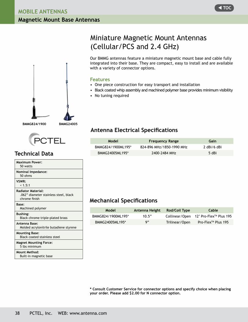
Miniature Magnetic Mount Antennas (Cellular/PCS and 2.4 GHz)Our BMMG antennas feature a miniature magnetic mount base and cable fully integrated into their base. They are compact, easy to install and are available with a variety of connector options.
Features• One piece construction for easy transport and installation• Black coated whip assembly and machined polymer base provides minimum visibility• No tuning required
Antenna Electrical Specifications
Mechanical Specifications
Model Antenna Height Rod/Coil Type Cable
BMMG824/1900ML195* 10.5” Collinear/Open 12’ Pro-FlexTM Plus 195
BMMG24005ML195* 9” Trilinear/Open Pro-FlexTM Plus 195
Technical Data Maximum Power:
50 watts
Nominal Impedance:50 ohms
VSWR:< 1.5:1
Radiator Material:.062” diameter stainless steel, black chrome finish
Base:Machined polymer
Bushing:Black chrome triple-plated brass
Antenna Base:Molded acrylonitrile butadiene styrene
Mounting Base:Black coated stainless steel
Magnet Mounting Force:5 lbs minimum
Mount Method:Built-in magnetic base
BMMG824/1900 BMMG24005
* Consult Customer Service for connector options and specify choice when placing your order. Please add $2.00 for N connector option.
38 PCTEL, Inc. WEB: www.antenna.com
t TOCMOBILE ANTENNAS
Magnetic Mount Base Antennas
PCTEL, Inc. WEB: www.antenna.com 39
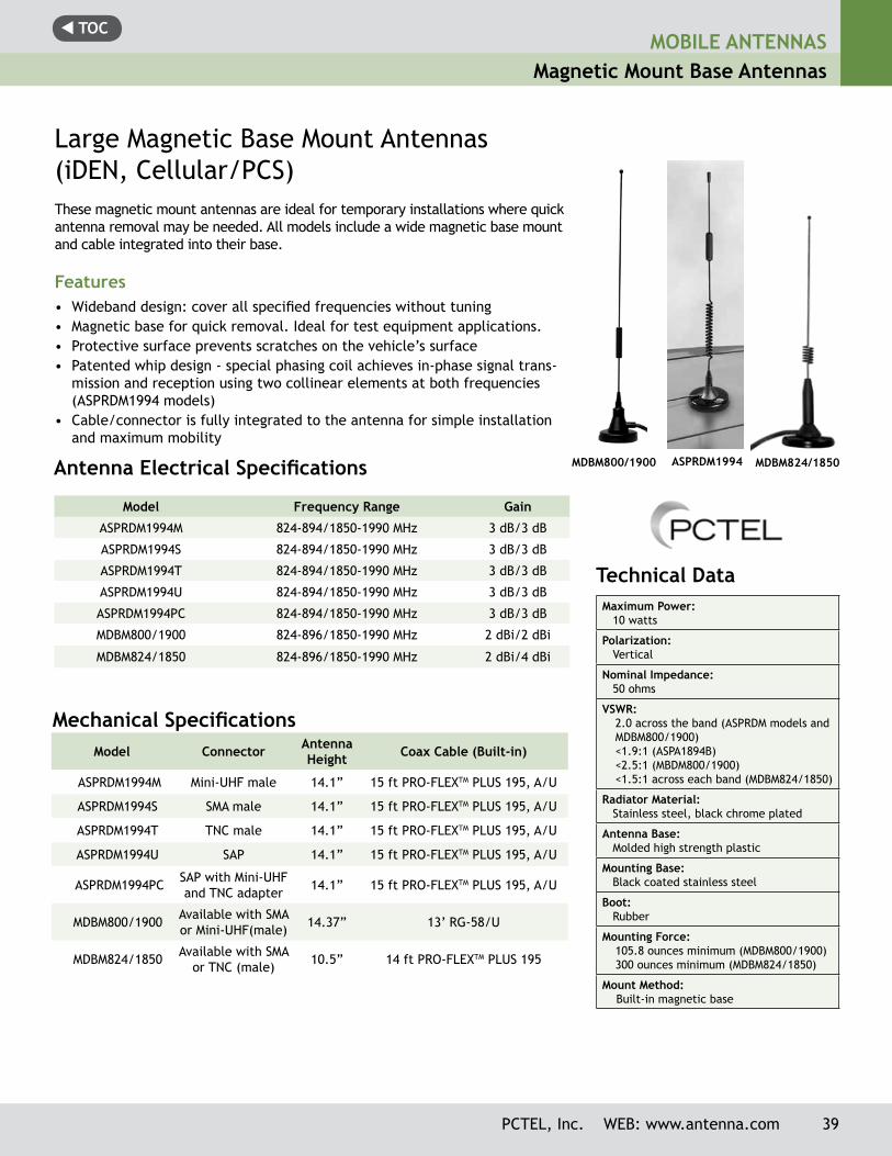
ASPRDM1994
Technical Data Maximum Power: 10 watts
Polarization: Vertical
Nominal Impedance: 50 ohms
VSWR:2.0 across the band (ASPRDM models and MDBM800/1900)<1.9:1 (ASPA1894B)<2.5:1 (MBDM800/1900)<1.5:1 across each band (MDBM824/1850)
Radiator Material: Stainless steel, black chrome plated
Antenna Base: Molded high strength plastic
Mounting Base: Black coated stainless steel
Boot: Rubber
Mounting Force:105.8 ounces minimum (MDBM800/1900)300 ounces minimum (MDBM824/1850)
Mount Method: Built-in magnetic base
MDBM824/1850MDBM800/1900
Large Magnetic Base Mount Antennas (iDEN, Cellular/PCS)These magnetic mount antennas are ideal for temporary installations where quick antenna removal may be needed. All models include a wide magnetic base mount and cable integrated into their base.
Features• Wideband design: cover all specified frequencies without tuning• Magnetic base for quick removal. Ideal for test equipment applications.• Protective surface prevents scratches on the vehicle’s surface• Patented whip design - special phasing coil achieves in-phase signal trans-
mission and reception using two collinear elements at both frequencies (ASPRDM1994 models)
• Cable/connector is fully integrated to the antenna for simple installation and maximum mobility
Model Frequency Range Gain
ASPRDM1994M 824-894/1850-1990 MHz 3 dB/3 dB
ASPRDM1994S 824-894/1850-1990 MHz 3 dB/3 dB
ASPRDM1994T 824-894/1850-1990 MHz 3 dB/3 dB
ASPRDM1994U 824-894/1850-1990 MHz 3 dB/3 dB
ASPRDM1994PC 824-894/1850-1990 MHz 3 dB/3 dB
MDBM800/1900 824-896/1850-1990 MHz 2 dBi/2 dBi
MDBM824/1850 824-896/1850-1990 MHz 2 dBi/4 dBi
Antenna Electrical Specifications
Mechanical SpecificationsModel Connector Antenna
Height Coax Cable (Built-in)
ASPRDM1994M Mini-UHF male 14.1” 15 ft PRO-FLEXTM PLUS 195, A/U
ASPRDM1994S SMA male 14.1” 15 ft PRO-FLEXTM PLUS 195, A/U
ASPRDM1994T TNC male 14.1” 15 ft PRO-FLEXTM PLUS 195, A/U
ASPRDM1994U SAP 14.1” 15 ft PRO-FLEXTM PLUS 195, A/U
ASPRDM1994PC SAP with Mini-UHF and TNC adapter 14.1” 15 ft PRO-FLEXTM PLUS 195, A/U
MDBM800/1900 Available with SMA or Mini-UHF(male) 14.37” 13’ RG-58/U
MDBM824/1850 Available with SMA or TNC (male) 10.5” 14 ft PRO-FLEXTM PLUS 195
t TOCMOBILE ANTENNASGlass Mount Antennas
Technical Data Maximum Power:
10 watts
Nominal Impedance:50 ohms
VSWR:<1.9:1
Radiator Material:0.090” 300 series stainless steel with black DURA-COAT™ finish
Cable:15 ft PRO-FLEX™ PLUS 195 cable
Mount Method:Glass mount
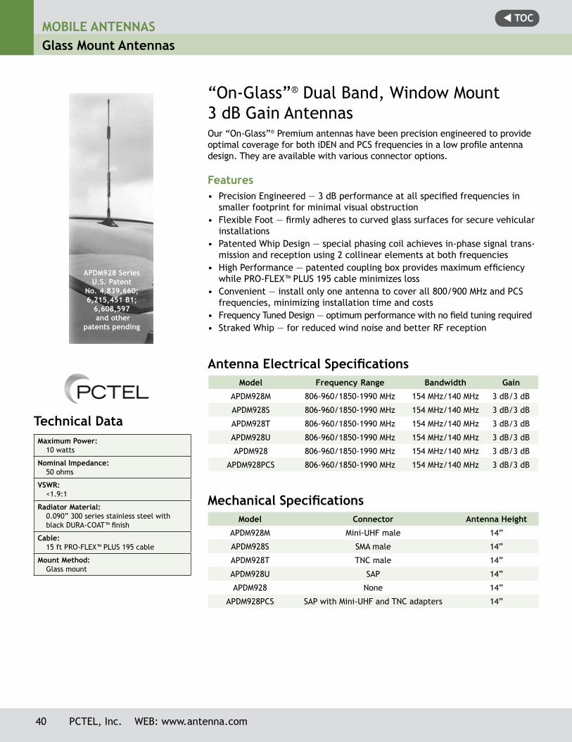
APDM928 SeriesU.S. Patent
No. 4,839,660; 6,215,451 B1;
6,608,597 and other
patents pending
“On-Glass”® Dual Band, Window Mount 3 dB Gain AntennasOur “On-Glass”® Premium antennas have been precision engineered to provide optimal coverage for both iDEN and PCS frequencies in a low profile antenna design. They are available with various connector options.
Features• Precision Engineered — 3 dB performance at all specified frequencies in
smaller footprint for minimal visual obstruction• Flexible Foot — firmly adheres to curved glass surfaces for secure vehicular
installations• Patented Whip Design — special phasing coil achieves in-phase signal trans-
mission and reception using 2 collinear elements at both frequencies• High Performance — patented coupling box provides maximum efficiency
while PRO-FLEX™ PLUS 195 cable minimizes loss• Convenient — install only one antenna to cover all 800/900 MHz and PCS
frequencies, minimizing installation time and costs• Frequency Tuned Design — optimum performance with no field tuning required• Straked Whip — for reduced wind noise and better RF reception
Model Frequency Range Bandwidth Gain
APDM928M 806-960/1850-1990 MHz 154 MHz/140 MHz 3 dB/3 dB
APDM928S 806-960/1850-1990 MHz 154 MHz/140 MHz 3 dB/3 dB
APDM928T 806-960/1850-1990 MHz 154 MHz/140 MHz 3 dB/3 dB
APDM928U 806-960/1850-1990 MHz 154 MHz/140 MHz 3 dB/3 dB
APDM928 806-960/1850-1990 MHz 154 MHz/140 MHz 3 dB/3 dB
APDM928PCS 806-960/1850-1990 MHz 154 MHz/140 MHz 3 dB/3 dB
Antenna Electrical Specifications
Mechanical SpecificationsModel Connector Antenna Height
APDM928M Mini-UHF male 14”
APDM928S SMA male 14”
APDM928T TNC male 14”
APDM928U SAP 14”
APDM928 None 14”
APDM928PCS SAP with Mini-UHF and TNC adapters 14”
40 PCTEL, Inc. WEB: www.antenna.com
t TOC
U.S. Patent No. 4,839,660 and 6,215,241 B1 and other
patents pending
Technical Data Maximum Power:
10 watts
Nominal Impedance:50 ohms
VSWR:<1.9:1
Radiator Material:0.39” flexible plastic
Coax Cable: 15 ft PRO-FLEX™ PLUS 195 cable
Whip Length:4 inches
Mounting Method:Glass mount
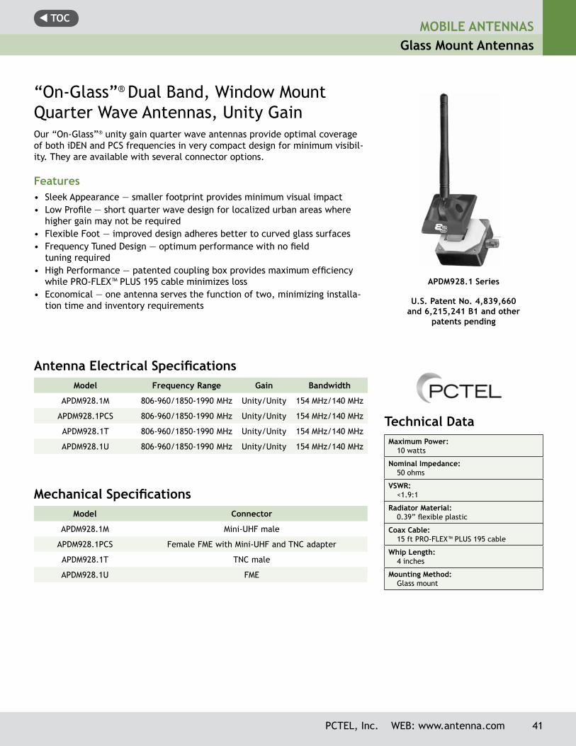
APDM928.1 Series
Antenna Electrical Specifications Model Frequency Range Gain Bandwidth
APDM928.1M 806-960/1850-1990 MHz Unity/Unity 154 MHz/140 MHz
APDM928.1PCS 806-960/1850-1990 MHz Unity/Unity 154 MHz/140 MHz
APDM928.1T 806-960/1850-1990 MHz Unity/Unity 154 MHz/140 MHz
APDM928.1U 806-960/1850-1990 MHz Unity/Unity 154 MHz/140 MHz
Mechanical SpecificationsModel Connector
APDM928.1M Mini-UHF male
APDM928.1PCS Female FME with Mini-UHF and TNC adapter
APDM928.1T TNC male
APDM928.1U FME
Our “On-Glass”® unity gain quarter wave antennas provide optimal coverage of both iDEN and PCS frequencies in very compact design for minimum visibil-ity. They are available with several connector options.
Features• Sleek Appearance — smaller footprint provides minimum visual impact• Low Profile — short quarter wave design for localized urban areas where
higher gain may not be required• Flexible Foot — improved design adheres better to curved glass surfaces• Frequency Tuned Design — optimum performance with no field
tuning required• High Performance — patented coupling box provides maximum efficiency
while PRO-FLEX™ PLUS 195 cable minimizes loss• Economical — one antenna serves the function of two, minimizing installa-
tion time and inventory requirements
“On-Glass”® Dual Band, Window Mount Quarter Wave Antennas, Unity Gain
MOBILE ANTENNASGlass Mount Antennas
PCTEL, Inc. WEB: www.antenna.com 41
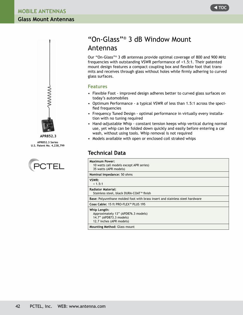
t TOCMOBILE ANTENNASGlass Mount Antennas
Technical Data Maximum Power:
10 watts (all models except APR series)35 watts (APR models)
Nominal Impedance: 50 ohms
VSWR:< 1.5:1
Radiator Material:Stainless steel, black DURA-COAT™ finish
Base: Polyurethane molded foot with brass insert and stainless steel hardware
Coax Cable: 15 ft PRO-FLEX™ PLUS 195
Whip Length:Approximately 13” (APD876.3 models)14.7” (APD873.3 models)12.7 inches (APR models)
Mounting Method: Glass mount
Our “On-Glass”® 3 dB antennas provide optimal coverage of 800 and 900 MHz frequencies with outstanding VSWR performance of <1.5:1. Their patented mount design features a compact coupling box and flexible foot that trans-mits and receives through glass without holes while firmly adhering to curved glass surfaces.
Features• Flexible Foot - improved design adheres better to curved glass surfaces on
today’s automobiles• Optimum Performance - a typical VSWR of less than 1.5:1 across the speci-
fied frequencies• Frequency Tuned Design - optimal performance in virtually every installa-
tion with no tuning required• Hand-adjustable Whip - constant tension keeps whip vertical during normal
use, yet whip can be folded down quickly and easily before entering a car wash, without using tools. Whip removal is not required
• Models available with open or enclosed coil straked whips
“On-Glass”® 3 dB Window MountAntennas
APR852.3 SeriesU.S. Patent No. 4,238,799
APR852.3
42 PCTEL, Inc. WEB: www.antenna.com
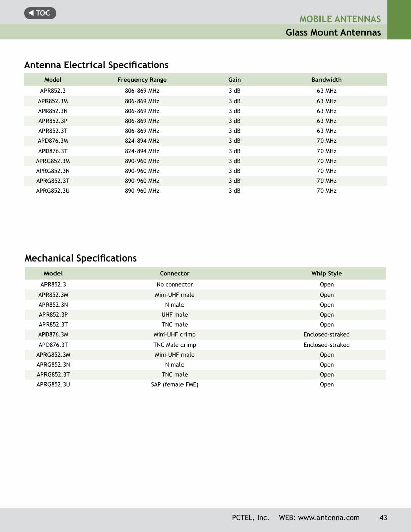
t TOC
Antenna Electrical SpecificationsModel Frequency Range Gain Bandwidth
APR852.3 806-869 MHz 3 dB 63 MHz
APR852.3M 806-869 MHz 3 dB 63 MHz
APR852.3N 806-869 MHz 3 dB 63 MHz
APR852.3P 806-869 MHz 3 dB 63 MHz
APR852.3T 806-869 MHz 3 dB 63 MHz
APD876.3M 824-894 MHz 3 dB 70 MHz
APD876.3T 824-894 MHz 3 dB 70 MHz
APRG852.3M 890-960 MHz 3 dB 70 MHz
APRG852.3N 890-960 MHz 3 dB 70 MHz
APRG852.3T 890-960 MHz 3 dB 70 MHz
APRG852.3U 890-960 MHz 3 dB 70 MHz
Mechanical SpecificationsModel Connector Whip Style
APR852.3 No connector Open
APR852.3M Mini-UHF male Open
APR852.3N N male Open
APR852.3P UHF male Open
APR852.3T TNC male Open
APD876.3M Mini-UHF crimp Enclosed-straked
APD876.3T TNC Male crimp Enclosed-straked
APRG852.3M Mini-UHF male Open
APRG852.3N N male Open
APRG852.3T TNC male Open
APRG852.3U SAP (female FME) Open
MOBILE ANTENNASGlass Mount Antennas
PCTEL, Inc. WEB: www.antenna.com 43
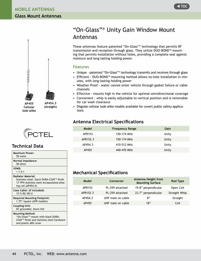
t TOC
Antenna Electrical Specifications Model Frequency Range Gain
APR153 150-174 MHz Unity
APR152.3 150-174 MHz Unity
AP454.3 410-512 MHz Unity
AP455 440-470 MHz Unity
Mechanical Specifications
Model Connector Antenna Height from Mounting Surface Rod Type
APR153 PL-259 attached 19.8” perpendicular Open Coil
APR152.3 PL-259 attached 23.7” perpendicular Straight Whip
AP454.3 UHF male on cable 8” Straight
AP455 UHF male on cable 18” Coil
These antennas feature patented “On-Glass”® technology that permits RF transmission and reception through glass. They utilize DUO-BOND™ mount-ing that permits installation without holes, providing a complete seal against moisture and long lasting holding power.
Features• Unique - patented “On-Glass”® technology transmits and receives through glass• Efficient - DUO-BOND™ mounting method allows no-hole installation in min-
utes, with long-lasting holding power• Weather Proof - water cannot enter vehicle through gasket failure or cable
channels• Effective - mounts high in the vehicle for optimal omnidirectional coverage• Convenient - whip is easily adjustable to vertical position and is removable
for car wash clearance• Disguise cellular look-alike models available for covert public safety applica-
tions
“On-Glass”® Unity Gain Window Mount Antennas
AP454.3(straight)
Technical Data Maximum Power:
50 watts
Normal Impedance:50 ohms
VSWR:< 1.5:1
Radiator Material:Stainless steel, black DURA-COAT™ finish 17-7PH stainless steel encapsulated phas-ing coil (AP454.5)
Coax Cable: (if included):15 ft RG-58/U
Required Mounting Footprint:1.75” square (APR models)
Coupling Unit:DC grounded, shunt-fed
Mounting Method:“On-Glass”® mount with black DURA-COAT™ finish and stainless steel hardware and plastic ABS cover
AP455Cellular
look-alike
44 PCTEL, Inc. WEB: www.antenna.com
MOBILE ANTENNASGlass Mount Antennas
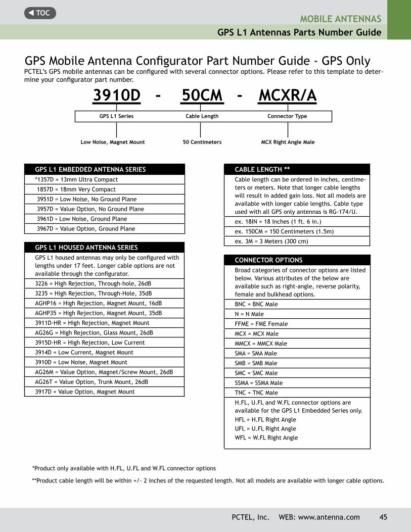
t TOCMOBILE ANTENNAS
GPS L1 Antennas Parts Number Guide
PCTEL, Inc. WEB: www.antenna.com 45
GPS L1 EMBEDDED ANTENNA SERIES*1357D = 13mm Ultra Compact
1857D = 18mm Very Compact
3951D = Low Noise, No Ground Plane
3957D = Value Option, No Ground Plane
3961D = Low Noise, Ground Plane
3967D = Value Option, Ground Plane
GPS L1 HOUSED ANTENNA SERIESGPS L1 housed antennas may only be configured with lengths under 17 feet. Longer cable options are not available through the configurator.
3226 = High Rejection, Through-hole, 26dB
3235 = High Rejection, Through-Hole, 35dB
AGHP16 = High Rejection, Magnet Mount, 16dB
AGHP35 = High Rejection, Magnet Mount, 35dB
3911D-HR = High Rejection, Magnet Mount
AG26G = High Rejection, Glass Mount, 26dB
3915D-HR = High Rejection, Low Current
3914D = Low Current, Magnet Mount
3910D = Low Noise, Magnet Mount
AG26M = Value Option, Magnet/Screw Mount, 26dB
AG26T = Value Option, Trunk Mount, 26dB
3917D = Value Option, Magnet Mount
CABLE LENGTH **Cable length can be ordered in inches, centime-ters or meters. Note that longer cable lengths will result in added gain loss. Not all models are available with longer cable lengths. Cable type used with all GPS only antennas is RG-174/U.
ex. 18IN = 18 Inches (1 ft. 6 in.)
ex. 150CM = 150 Centimeters (1.5m)
ex. 3M = 3 Meters (300 cm)
CONNECTOR OPTIONS Broad categories of connector options are listed below. Various attributes of the below are available such as right-angle, reverse polarity, female and bulkhead options.
BNC = BNC Male
N = N Male
FFME = FME Female
MCX = MCX Male
MMCX = MMCX Male
SMA = SMA Male
SMB = SMB Male
SMC = SMC Male
SSMA = SSMA Male
TNC = TNC Male
H.FL, U.FL and W.FL connector options are available for the GPS L1 Embedded Series only.HFL = H.FL Right AngleUFL = U.FL Right AngleWFL = W.FL Right Angle
PCTEL’s GPS mobile antennas can be configured with several connector options. Please refer to this template to deter-mine your configurator part number.
GPS Mobile Antenna Configurator Part Number Guide - GPS Only
3910D - 50CM - MCXR/A
**Product cable length will be within +/- 2 inches of the requested length. Not all models are available with longer cable options.
*Product only available with H.FL, U.FL and W.FL connector options
GPS L1 Series Cable Length Connector Type
Low Noise, Magnet Mount 50 Centimeters MCX Right Angle Male
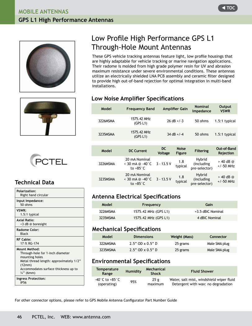
t TOC
46 PCTEL, Inc. WEB: www.antenna.com
MOBILE ANTENNASGPS L1 High Performance Antennas
Technical Data Polarization:
Right hand circular
Input Impedance:50 ohms
VSWR:1.5:1 typical
Axial Ratio:<3 dB @ boresight
Radome Color:Black
RF Cable:17 ft RG-174
Mount Method:Through-hole for 1-inch diametermounting holesMetal thread length: approximately 1/2”(12mm)Accommodates surface thickness up to¼” (6mm)
Ingress Protection:IP56
Low Profile High Performance GPS L1 Through-Hole Mount AntennasThese GPS vehicle tracking antennas feature light, low profile housings that are highly adaptable for vehicle tracking or marine navigation applications.Their radome is molded from high grade polymer resin for UV and abrasion maximum resistance under severe environmental conditions. These antennas utilize an electrically shielded LNA PCB assembly and ceramic filter designed to provide high out-of-band rejection for optimal integration in multi-band installations.
Low Noise Amplifier Specifications
Model Frequency Band Amplifier Gain Nominal Impedance
Output VSWR
3226MSMA 1575.42 MHz(GPS L1) 26 dB +/-3 50 ohms 1.5:1 typical
3235MSMA 1575.42 MHz(GPS L1) 34 dB +/-4 50 ohms 1.5:1 typical
Model DC Current DC Voltage
Noise Figure Filtering Out-of-Band
Rejection
3226MSMA20 mA Nominal
< 30 mA @ -40°C to +85°C
3 - 13.5 V 1.8 typical
Hybrid (including
pre-selector)
> 40 dB @ +/-50 MHz
3235MSMA20 mA Nominal
< 30 mA @ -40°C to +85°C
3 - 13.5 V 1.8 typical
Hybrid (including
pre-selector)
> 40 dB @ +/-50 MHz
Antenna Electrical Specifications
Temperature Range Humidity Mechanical
Shock Fluid Shower
-40°C to +85°C (operating) 95% 25 g
maximumWater, salt mist, windshield wiper fluid
Detergent with wax: no degradation
Environmental Specifications
Model Frequency Gain
3226MSMA 1575.42 MHz (GPS L1) +3.5 dBiC Nominal
3235MSMA 1575.42 MHz (GPS L1) 4 dBiC Nominal
Mechanical SpecificationsModel Dimensions Weight (Mass) Connector
3226MSMA 2.5” OD x 0.5” D 25 grams Male SMA plug
3235MSMA 2.5” OD x 0.5” D 25 grams Male SMA plug
For other connector options, please refer to GPS Mobile Antenna Configurator Part Number Guide
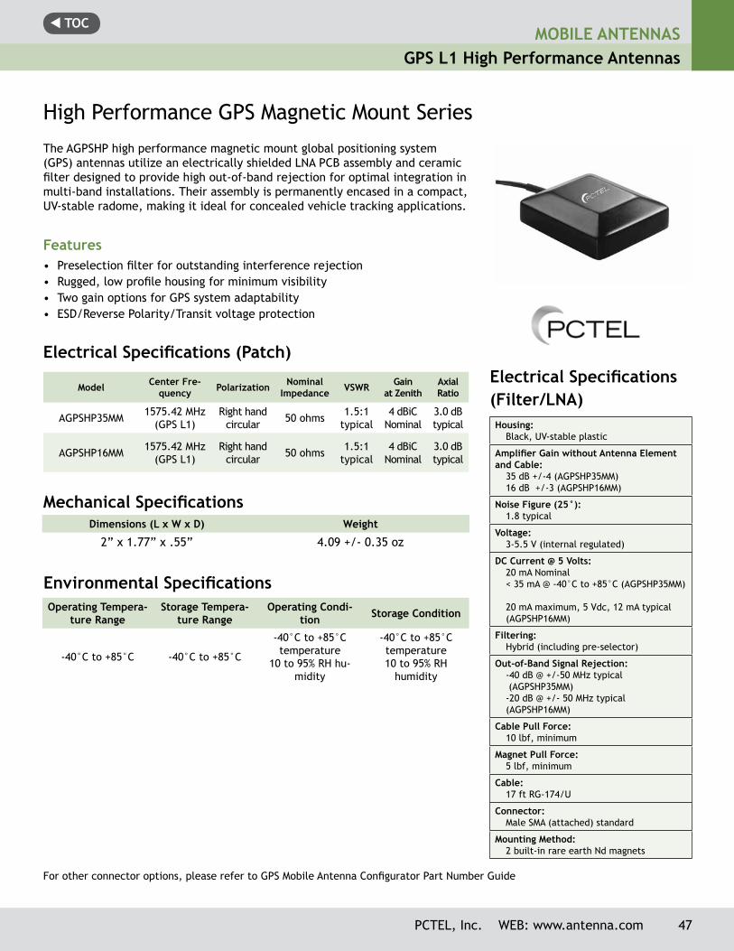
t TOCMOBILE ANTENNAS
GPS L1 High Performance Antennas
PCTEL, Inc. WEB: www.antenna.com 47
High Performance GPS Magnetic Mount Series
The AGPSHP high performance magnetic mount global positioning system (GPS) antennas utilize an electrically shielded LNA PCB assembly and ceramic filter designed to provide high out-of-band rejection for optimal integration in multi-band installations. Their assembly is permanently encased in a compact, UV-stable radome, making it ideal for concealed vehicle tracking applications.
Features• Preselection filter for outstanding interference rejection• Rugged, low profile housing for minimum visibility• Two gain options for GPS system adaptability • ESD/Reverse Polarity/Transit voltage protection
Dimensions (L x W x D) Weight
2” x 1.77” x .55” 4.09 +/- 0.35 oz
Environmental Specifications
Mechanical Specifications
Operating Tempera-ture Range
Storage Tempera-ture Range
Operating Condi-tion Storage Condition
-40°C to +85°C -40°C to +85°C
-40°C to +85°C temperature
10 to 95% RH hu-midity
-40°C to +85°C temperature10 to 95% RH
humidity
Model Center Fre-quency Polarization Nominal
Impedance VSWR Gain at Zenith
AxialRatio
AGPSHP35MM 1575.42 MHz (GPS L1)
Right hand circular 50 ohms 1.5:1
typical4 dBiC
Nominal3.0 dB typical
AGPSHP16MM 1575.42 MHz (GPS L1)
Right hand circular 50 ohms 1.5:1
typical4 dBiC
Nominal3.0 dB typical
Electrical Specifications (Patch)Electrical Specifications(Filter/LNA) Housing:
Black, UV-stable plastic
Amplifier Gain without Antenna Element and Cable:
35 dB +/-4 (AGPSHP35MM)16 dB +/-3 (AGPSHP16MM)
Noise Figure (25°):1.8 typical
Voltage:3-5.5 V (internal regulated)
DC Current @ 5 Volts:20 mA Nominal< 35 mA @ -40°C to +85°C (AGPSHP35MM)
20 mA maximum, 5 Vdc, 12 mA typical (AGPSHP16MM)
Filtering:Hybrid (including pre-selector)
Out-of-Band Signal Rejection:-40 dB @ +/-50 MHz typical (AGPSHP35MM)-20 dB @ +/- 50 MHz typical(AGPSHP16MM)
Cable Pull Force:10 lbf, minimum
Magnet Pull Force:5 lbf, minimum
Cable:17 ft RG-174/U
Connector:Male SMA (attached) standard
Mounting Method:2 built-in rare earth Nd magnets
For other connector options, please refer to GPS Mobile Antenna Configurator Part Number Guide
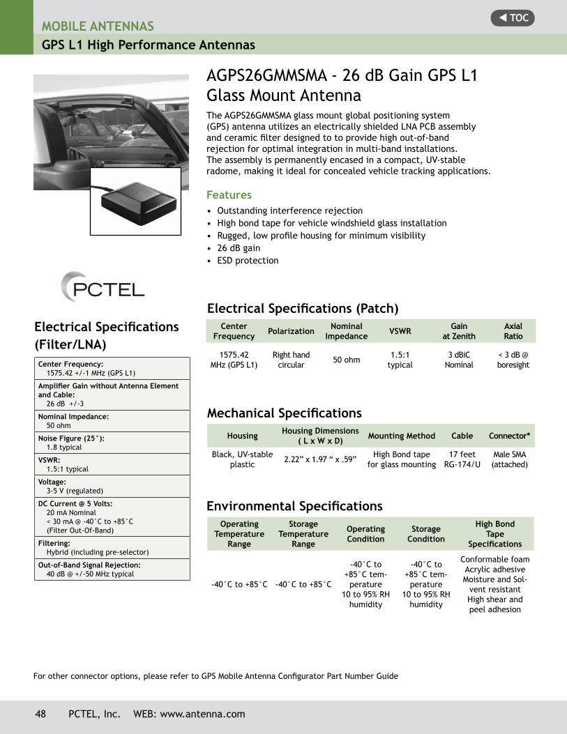
t TOCMOBILE ANTENNASGPS L1 High Performance Antennas
Electrical Specifications(Filter/LNA) Center Frequency:
1575.42 +/-1 MHz (GPS L1)
Amplifier Gain without Antenna Element and Cable:
26 dB +/-3
Nominal Impedance:50 ohm
Noise Figure (25°):1.8 typical
VSWR:1.5:1 typical
Voltage:3-5 V (regulated)
DC Current @ 5 Volts:20 mA Nominal< 30 mA @ -40°C to +85°C(Filter Out-Of-Band)
Filtering:Hybrid (including pre-selector)
Out-of-Band Signal Rejection:40 dB @ +/-50 MHz typical
The AGPS26GMMSMA glass mount global positioning system(GPS) antenna utilizes an electrically shielded LNA PCB assemblyand ceramic filter designed to to provide high out-of-bandrejection for optimal integration in multi-band installations.The assembly is permanently encased in a compact, UV-stableradome, making it ideal for concealed vehicle tracking applications.
Features• Outstanding interference rejection• High bond tape for vehicle windshield glass installation• Rugged, low profile housing for minimum visibility• 26 dB gain• ESD protection
AGPS26GMMSMA - 26 dB Gain GPS L1 Glass Mount Antenna
Center Frequency Polarization Nominal
Impedance VSWR Gain at Zenith
AxialRatio
1575.42 MHz (GPS L1)
Right hand circular 50 ohm 1.5:1
typical3 dBiC
Nominal< 3 dB @ boresight
Electrical Specifications (Patch)
Mechanical Specifications
Housing Housing Dimensions ( L x W x D) Mounting Method Cable Connector*
Black, UV-stable plastic 2.22” x 1.97 “ x .59” High Bond tape
for glass mounting17 feet
RG-174/UMale SMA (attached)
Environmental SpecificationsOperating
Temperature Range
Storage Temperature
Range
Operating Condition
Storage Condition
High BondTape
Specifications
-40°C to +85°C -40°C to +85°C
-40°C to +85°C tem-
perature 10 to 95% RH
humidity
-40°C to +85°C tem-
perature10 to 95% RH
humidity
Conformable foamAcrylic adhesiveMoisture and Sol-
vent resistantHigh shear and peel adhesion
For other connector options, please refer to GPS Mobile Antenna Configurator Part Number Guide
48 PCTEL, Inc. WEB: www.antenna.com
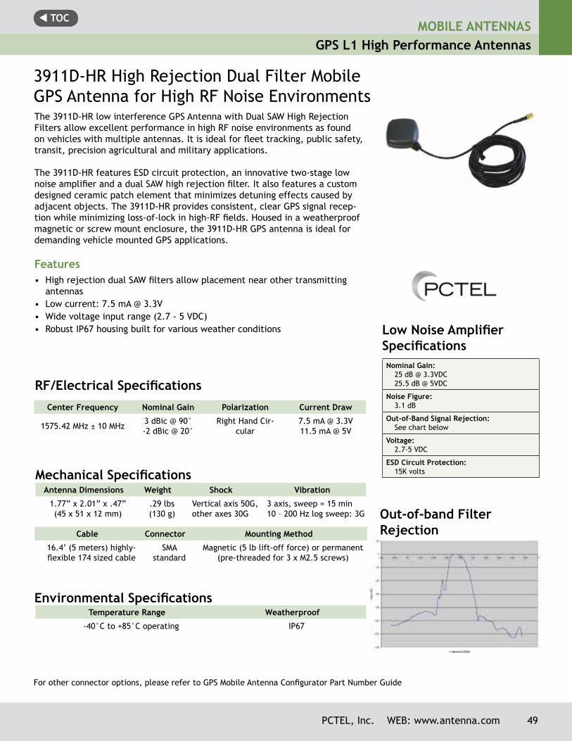
t TOCMOBILE ANTENNAS
GPS L1 High Performance Antennas
Low Noise Amplifier SpecificationsNominal Gain:
25 dB @ 3.3VDC25.5 dB @ 5VDC
Noise Figure:3.1 dB
Out-of-Band Signal Rejection:See chart below
Voltage:2.7-5 VDC
ESD Circuit Protection:15K volts
3911D-HR High Rejection Dual Filter Mobile GPS Antenna for High RF Noise EnvironmentsThe 3911D-HR low interference GPS Antenna with Dual SAW High Rejection Filters allow excellent performance in high RF noise environments as found on vehicles with multiple antennas. It is ideal for fleet tracking, public safety, transit, precision agricultural and military applications.
The 3911D-HR features ESD circuit protection, an innovative two-stage low noise amplifier and a dual SAW high rejection filter. It also features a custom designed ceramic patch element that minimizes detuning effects caused by adjacent objects. The 3911D-HR provides consistent, clear GPS signal recep-tion while minimizing loss-of-lock in high-RF fields. Housed in a weatherproof magnetic or screw mount enclosure, the 3911D-HR GPS antenna is ideal for demanding vehicle mounted GPS applications.
Features• High rejection dual SAW filters allow placement near other transmitting
antennas• Low current: 7.5 mA @ 3.3V• Wide voltage input range (2.7 - 5 VDC)• Robust IP67 housing built for various weather conditions
Center Frequency Nominal Gain Polarization Current Draw
1575.42 MHz ± 10 MHz 3 dBic @ 90°-2 dBic @ 20°
Right Hand Cir-cular
7.5 mA @ 3.3V 11.5 mA @ 5V
RF/Electrical Specifications
Antenna Dimensions Weight Shock Vibration
1.77” x 2.01” x .47” (45 x 51 x 12 mm)
.29 lbs(130 g)
Vertical axis 50G, other axes 30G
3 axis, sweep = 15 min10 – 200 Hz log sweep: 3G
Mechanical Specifications
Environmental Specifications Temperature Range Weatherproof
-40°C to +85°C operating IP67
Cable Connector Mounting Method
16.4’ (5 meters) highly-flexible 174 sized cable
SMA standard
Magnetic (5 lb lift-off force) or permanent (pre-threaded for 3 x M2.5 screws)
For other connector options, please refer to GPS Mobile Antenna Configurator Part Number Guide
Out-of-band Filter Rejection
PCTEL, Inc. WEB: www.antenna.com 49
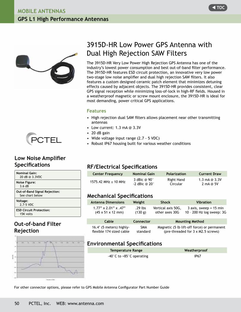
t TOCMOBILE ANTENNASGPS L1 High Performance Antennas
3915D-HR Low Power GPS Antenna with Dual High Rejection SAW FiltersThe 3915D-HR Very Low Power High Rejection GPS Antenna has one of the industry’s lowest power consumption and best out-of-band filter performance. The 3915D-HR features ESD circuit protection, an innovative very low power two-stage low noise amplifier and dual high rejection SAW filters. It also features a custom designed ceramic patch element that minimizes detuning effects caused by adjacent objects. The 3915D-HR provides consistent, clear GPS signal reception while minimizing loss-of-lock in high-RF fields. Housed in a weatherproof magnetic or screw mount enclosure, the 3915D-HR is ideal for most demanding, power critical GPS applications.
Features• High rejection dual SAW filters allows placement near other transmitting
antennas• Low current: 1.3 mA @ 3.3V• 20 dB gain • Wide voltage input range (2.7 - 5 VDC)• Robust IP67 housing built for various weather conditions
Low Noise Amplifier SpecificationsNominal Gain:
20 dB @ 3.3VDC
Noise Figure:3.6 dB
Out-of-Band Signal Rejection:See chart below
Voltage:2.7-5 VDC
ESD Circuit Protection:15K volts
Center Frequency Nominal Gain Polarization Current Draw
1575.42 MHz ± 10 MHz 3 dBic @ 90°-2 dBic @ 20°
Right HandCircular
1.3 mA @ 3.3V 2 mA @ 5V
RF/Electrical Specifications
Antenna Dimensions Weight Shock Vibration
1.77” x 2.01” x .47” (45 x 51 x 12 mm)
.29 lbs(130 g)
Vertical axis 50G, other axes 30G
3 axis, sweep = 15 min10 – 200 Hz log sweep: 3G
Mechanical Specifications
Environmental Specifications Temperature Range Weatherproof
-40°C to +85°C operating IP67
Cable Connector Mounting Method
16.4’ (5 meters) highly-flexible 174 sized cable
SMA standard
Magnetic (5 lb lift-off force) or permanent (pre-threaded for 3 x M2.5 screws)
For other connector options, please refer to GPS Mobile Antenna Configurator Part Number Guide
Out-of-band Filter Rejection
50 PCTEL, Inc. WEB: www.antenna.com
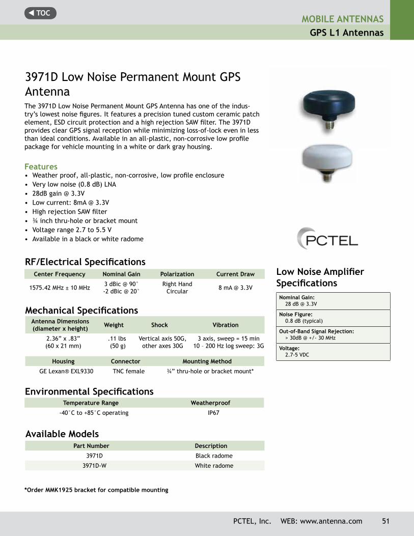
t TOCMOBILE ANTENNAS
GPS L1 Antennas
3971D Low Noise Permanent Mount GPS AntennaThe 3971D Low Noise Permanent Mount GPS Antenna has one of the indus-try’s lowest noise figures. It features a precision tuned custom ceramic patch element, ESD circuit protection and a high rejection SAW filter. The 3971D provides clear GPS signal reception while minimizing loss-of-lock even in less than ideal conditions. Available in an all-plastic, non-corrosive low profile package for vehicle mounting in a white or dark gray housing.
Features• Weather proof, all-plastic, non-corrosive, low profile enclosure• Very low noise (0.8 dB) LNA• 28dB gain @ 3.3V• Low current: 8mA @ 3.3V• High rejection SAW filter• ¾ inch thru-hole or bracket mount• Voltage range 2.7 to 5.5 V• Available in a black or white radome
Low Noise Amplifier Specifications Nominal Gain:
28 dB @ 3.3V
Noise Figure:0.8 dB (typical)
Out-of-Band Signal Rejection:> 30dB @ +/- 30 MHz
Voltage:2.7-5 VDC
Center Frequency Nominal Gain Polarization Current Draw
1575.42 MHz ± 10 MHz 3 dBic @ 90°-2 dBic @ 20°
Right HandCircular 8 mA @ 3.3V
RF/Electrical Specifications
Antenna Dimensions(diameter x height) Weight Shock Vibration
2.36” x .83” (60 x 21 mm)
.11 lbs (50 g)
Vertical axis 50G, other axes 30G
3 axis, sweep = 15 min10 – 200 Hz log sweep: 3G
Mechanical Specifications
Environmental Specifications Temperature Range Weatherproof
-40°C to +85°C operating IP67
Housing Connector Mounting Method
GE Lexan® EXL9330 TNC female ¾” thru-hole or bracket mount*
Available ModelsPart Number Description
3971D Black radome
3971D-W White radome
*Order MMK1925 bracket for compatible mounting
PCTEL, Inc. WEB: www.antenna.com 51
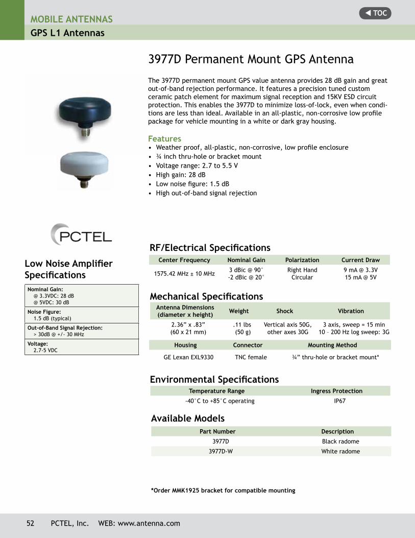
t TOCMOBILE ANTENNASGPS L1 Antennas
3977D Permanent Mount GPS Antenna
The 3977D permanent mount GPS value antenna provides 28 dB gain and great out-of-band rejection performance. It features a precision tuned custom ceramic patch element for maximum signal reception and 15KV ESD circuit protection. This enables the 3977D to minimize loss-of-lock, even when condi-tions are less than ideal. Available in an all-plastic, non-corrosive low profile package for vehicle mounting in a white or dark gray housing.
Features• Weather proof, all-plastic, non-corrosive, low profile enclosure• ¾ inch thru-hole or bracket mount• Voltage range: 2.7 to 5.5 V• High gain: 28 dB • Low noise figure: 1.5 dB• High out-of-band signal rejection
Low Noise Amplifier SpecificationsNominal Gain:
@ 3.3VDC: 28 dB @ 5VDC: 30 dB
Noise Figure:1.5 dB (typical)
Out-of-Band Signal Rejection:> 30dB @ +/- 30 MHz
Voltage:2.7-5 VDC
Center Frequency Nominal Gain Polarization Current Draw
1575.42 MHz ± 10 MHz 3 dBic @ 90°-2 dBic @ 20°
Right Hand Circular
9 mA @ 3.3V15 mA @ 5V
RF/Electrical Specifications
Antenna Dimensions(diameter x height) Weight Shock Vibration
2.36” x .83” (60 x 21 mm)
.11 lbs (50 g)
Vertical axis 50G, other axes 30G
3 axis, sweep = 15 min10 – 200 Hz log sweep: 3G
Mechanical Specifications
Environmental Specifications Temperature Range Ingress Protection
-40°C to +85°C operating IP67
Housing Connector Mounting Method
GE Lexan EXL9330 TNC female ¾” thru-hole or bracket mount*
Part Number Description
3977D Black radome
3977D-W White radome
*Order MMK1925 bracket for compatible mounting
Available Models
52 PCTEL, Inc. WEB: www.antenna.com
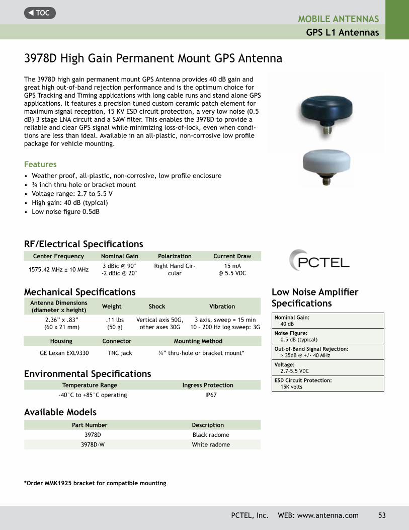
t TOC
3978D High Gain Permanent Mount GPS Antenna
The 3978D high gain permanent mount GPS Antenna provides 40 dB gain and great high out-of-band rejection performance and is the optimum choice for GPS Tracking and Timing applications with long cable runs and stand alone GPS applications. It features a precision tuned custom ceramic patch element for maximum signal reception, 15 KV ESD circuit protection, a very low noise (0.5 dB) 3 stage LNA circuit and a SAW filter. This enables the 3978D to provide a reliable and clear GPS signal while minimizing loss-of-lock, even when condi-tions are less than ideal. Available in an all-plastic, non-corrosive low profile package for vehicle mounting.
Features• Weather proof, all-plastic, non-corrosive, low profile enclosure• ¾ inch thru-hole or bracket mount• Voltage range: 2.7 to 5.5 V• High gain: 40 dB (typical)• Low noise figure 0.5dB
Part Number Description
3978D Black radome
3978D-W White radome
Available Models
Low Noise Amplifier SpecificationsNominal Gain:
40 dB
Noise Figure:0.5 dB (typical)
Out-of-Band Signal Rejection:> 35dB @ +/- 40 MHz
Voltage:2.7-5.5 VDC
ESD Circuit Protection:15K volts
Center Frequency Nominal Gain Polarization Current Draw
1575.42 MHz ± 10 MHz 3 dBic @ 90°-2 dBic @ 20°
Right Hand Cir-cular
15 mA @ 5.5 VDC
RF/Electrical Specifications
Antenna Dimensions(diameter x height) Weight Shock Vibration
2.36” x .83” (60 x 21 mm)
.11 lbs(50 g)
Vertical axis 50G, other axes 30G
3 axis, sweep = 15 min10 – 200 Hz log sweep: 3G
Mechanical Specifications
Environmental Specifications Temperature Range Ingress Protection
-40°C to +85°C operating IP67
Housing Connector Mounting Method
GE Lexan EXL9330 TNC jack ¾” thru-hole or bracket mount*
*Order MMK1925 bracket for compatible mounting
MOBILE ANTENNASGPS L1 Antennas
PCTEL, Inc. WEB: www.antenna.com 53
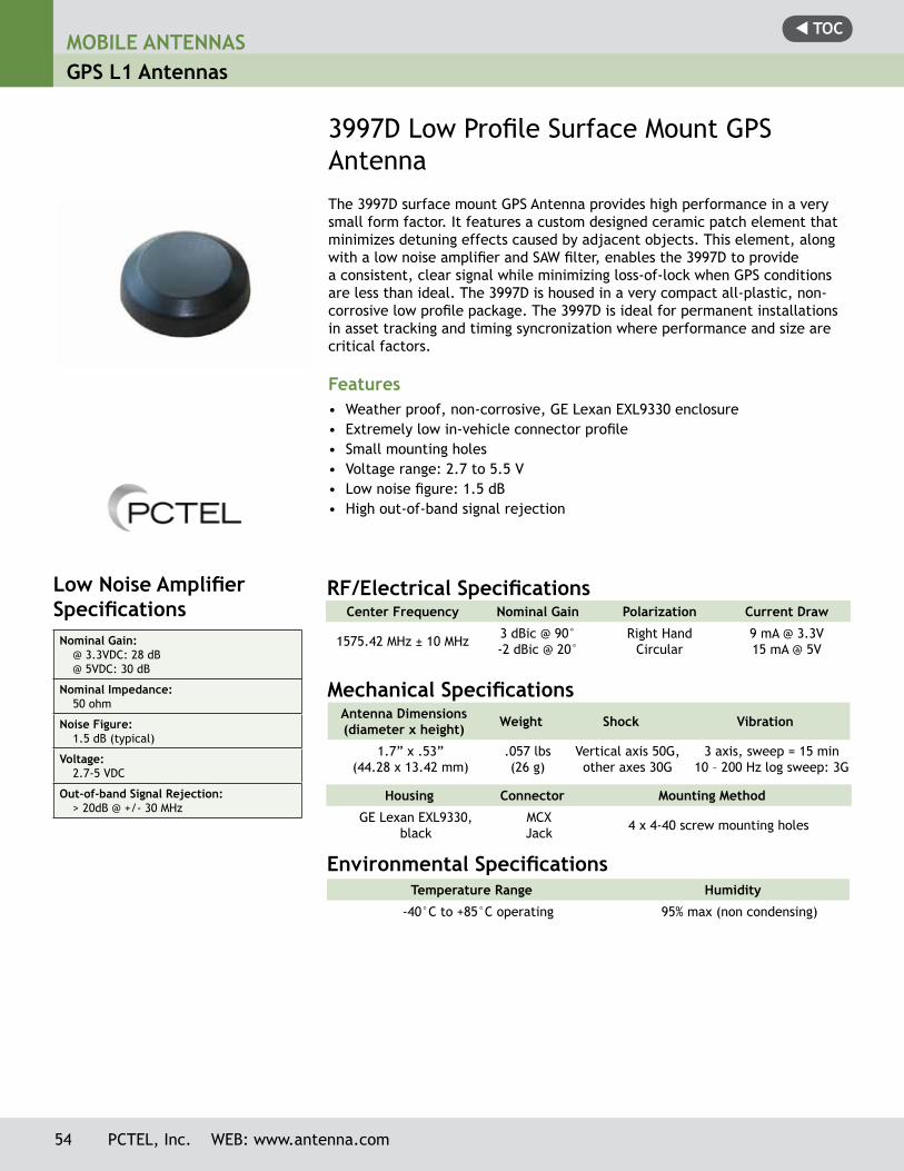
t TOCMOBILE ANTENNASGPS L1 Antennas
54 PCTEL, Inc. WEB: www.antenna.com
3997D Low Profile Surface Mount GPS AntennaThe 3997D surface mount GPS Antenna provides high performance in a very small form factor. It features a custom designed ceramic patch element that minimizes detuning effects caused by adjacent objects. This element, along with a low noise amplifier and SAW filter, enables the 3997D to providea consistent, clear signal while minimizing loss-of-lock when GPS conditions are less than ideal. The 3997D is housed in a very compact all-plastic, non-corrosive low profile package. The 3997D is ideal for permanent installations in asset tracking and timing syncronization where performance and size are critical factors.
Features• Weather proof, non-corrosive, GE Lexan EXL9330 enclosure• Extremely low in-vehicle connector profile• Small mounting holes• Voltage range: 2.7 to 5.5 V• Low noise figure: 1.5 dB• High out-of-band signal rejection
Low Noise Amplifier SpecificationsNominal Gain:
@ 3.3VDC: 28 dB @ 5VDC: 30 dB
Nominal Impedance:50 ohm
Noise Figure:1.5 dB (typical)
Voltage:2.7-5 VDC
Out-of-band Signal Rejection:> 20dB @ +/- 30 MHz
Center Frequency Nominal Gain Polarization Current Draw
1575.42 MHz ± 10 MHz 3 dBic @ 90°-2 dBic @ 20°
Right Hand Circular
9 mA @ 3.3V15 mA @ 5V
RF/Electrical Specifications
Antenna Dimensions(diameter x height) Weight Shock Vibration
1.7” x .53”(44.28 x 13.42 mm)
.057 lbs(26 g)
Vertical axis 50G, other axes 30G
3 axis, sweep = 15 min10 – 200 Hz log sweep: 3G
Mechanical Specifications
Environmental Specifications Temperature Range Humidity
-40°C to +85°C operating 95% max (non condensing)
Housing Connector Mounting Method
GE Lexan EXL9330, black
MCX Jack 4 x 4-40 screw mounting holes
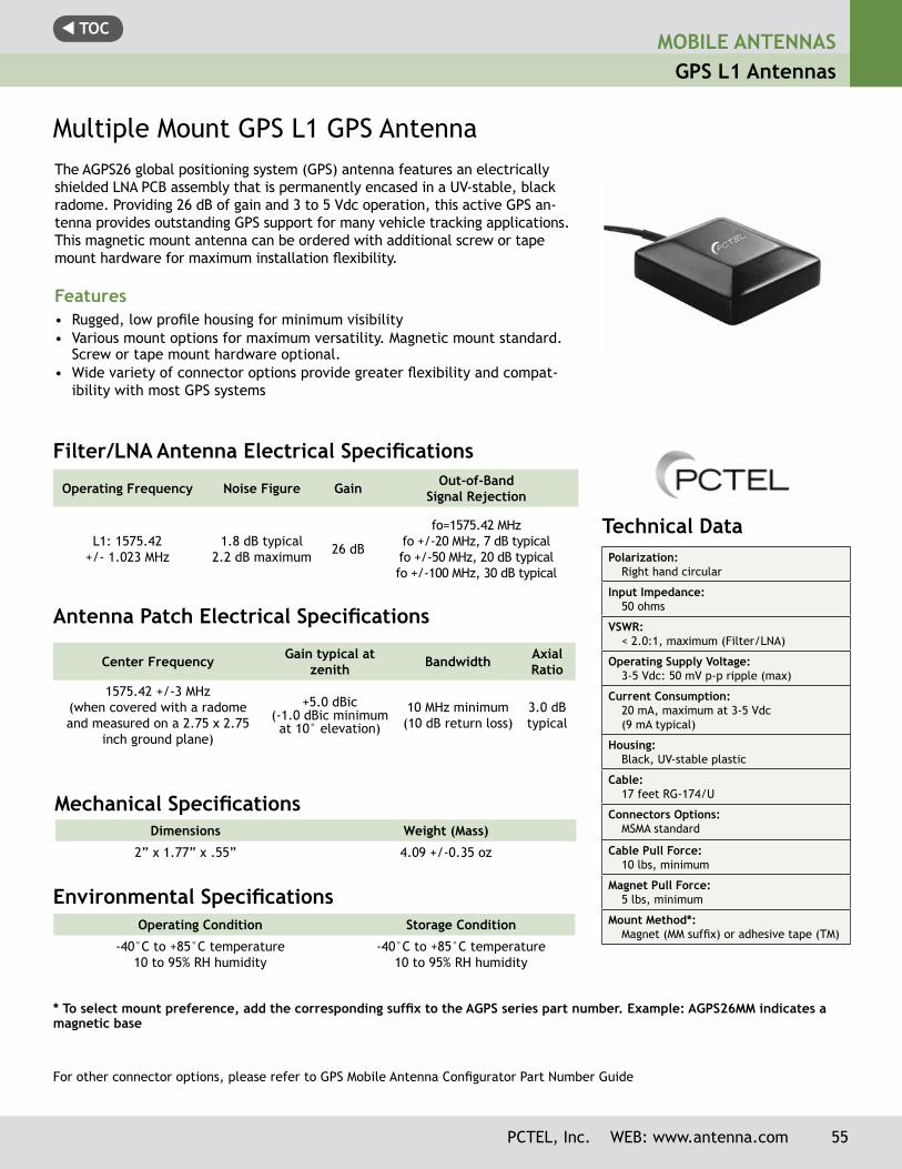
t TOCMOBILE ANTENNAS
GPS L1 Antennas
PCTEL, Inc. WEB: www.antenna.com 55
Technical Data Polarization:
Right hand circular
Input Impedance:50 ohms
VSWR:< 2.0:1, maximum (Filter/LNA)
Operating Supply Voltage:3-5 Vdc: 50 mV p-p ripple (max)
Current Consumption:20 mA, maximum at 3-5 Vdc (9 mA typical)
Housing:Black, UV-stable plastic
Cable:17 feet RG-174/U
Connectors Options:MSMA standard
Cable Pull Force:10 lbs, minimum
Magnet Pull Force:5 lbs, minimum
Mount Method*:Magnet (MM suffix) or adhesive tape (TM)
Multiple Mount GPS L1 GPS AntennaThe AGPS26 global positioning system (GPS) antenna features an electrically shielded LNA PCB assembly that is permanently encased in a UV-stable, black radome. Providing 26 dB of gain and 3 to 5 Vdc operation, this active GPS an-tenna provides outstanding GPS support for many vehicle tracking applications. This magnetic mount antenna can be ordered with additional screw or tape mount hardware for maximum installation flexibility.
Features• Rugged, low profile housing for minimum visibility• Various mount options for maximum versatility. Magnetic mount standard.
Screw or tape mount hardware optional.• Wide variety of connector options provide greater flexibility and compat-
ibility with most GPS systems
Operating Frequency Noise Figure Gain Out-of-Band Signal Rejection
L1: 1575.42+/- 1.023 MHz
1.8 dB typical 2.2 dB maximum 26 dB
fo=1575.42 MHz fo +/-20 MHz, 7 dB typicalfo +/-50 MHz, 20 dB typicalfo +/-100 MHz, 30 dB typical
Dimensions Weight (Mass)
2” x 1.77” x .55” 4.09 +/-0.35 oz
* To select mount preference, add the corresponding suffix to the AGPS series part number. Example: AGPS26MM indicates a magnetic base
Filter/LNA Antenna Electrical Specifications
Operating Condition Storage Condition
-40°C to +85°C temperature 10 to 95% RH humidity
-40°C to +85°C temperature10 to 95% RH humidity
Environmental Specifications
Mechanical Specifications
Center Frequency Gain typical at zenith Bandwidth Axial
Ratio
1575.42 +/-3 MHz(when covered with a radome and measured on a 2.75 x 2.75
inch ground plane)
+5.0 dBic(-1.0 dBic minimum at 10° elevation)
10 MHz minimum (10 dB return loss)
3.0 dB typical
Antenna Patch Electrical Specifications
For other connector options, please refer to GPS Mobile Antenna Configurator Part Number Guide
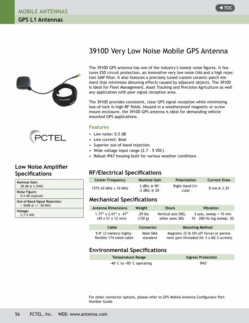
t TOCMOBILE ANTENNASGPS L1 Antennas
3910D Very Low Noise Mobile GPS Antenna
The 3910D GPS antenna has one of the industry’s lowest noise figures. It fea-tures ESD circuit protection, an innovative very low noise LNA and a high rejec-tion SAW filter. It also features a precisely tuned custom ceramic patch ele-ment that minimizes detuning effects caused by adjacent objects. The 3910D is ideal for Fleet Management, Asset Tracking and Precision Agriculture as well any application with poor signal reception area.
The 3910D provides consistent, clear GPS signal reception while minimizing loss-of-lock in high-RF fields. Housed in a weatherproof magnetic or screw mount enclosure, the 3910D GPS antenna is ideal for demanding vehicle mounted GPS applications.
Features• Low noise: 0.5 dB• Low current: 8mA• Superior out-of-band rejection• Wide voltage input range (2.7 - 5 VDC)• Robust IP67 housing built for various weather conditions
Low Noise Amplifier SpecificationsNominal Gain:
28 dB @ 3.3VDC
Noise Figure:0.5 dB (typical)
Out-of-Band Signal Rejection:> 30dB @ +/- 30 MHz
Voltage:2.7-5 VDC
Center Frequency Nominal Gain Polarization Current Draw
1575.42 MHz ± 10 MHz 3 dBic @ 90°-2 dBic @ 20°
Right Hand Cir-cular 8 mA @ 3.3V
RF/Electrical Specifications
Antenna Dimensions Weight Shock Vibration
1.77” x 2.01” x .47” (45 x 51 x 12 mm)
.29 lbs(130 g)
Vertical axis 50G, other axes 30G
3 axis, sweep = 15 min10 – 200 Hz log sweep: 3G
Mechanical Specifications
Environmental Specifications Temperature Range Ingress Protection
-40°C to +85°C operating IP67
Cable Connector Mounting Method
9.8’ (3 meters) highly-flexible 174 sized cable
Male SMA standard
Magnetic (5 lb lift-off force) or perma-nent (pre-threaded for 3 x M2.5 screws)
56 PCTEL, Inc. WEB: www.antenna.com
For other connector options, please refer to GPS Mobile Antenna Configurator Part Number Guide
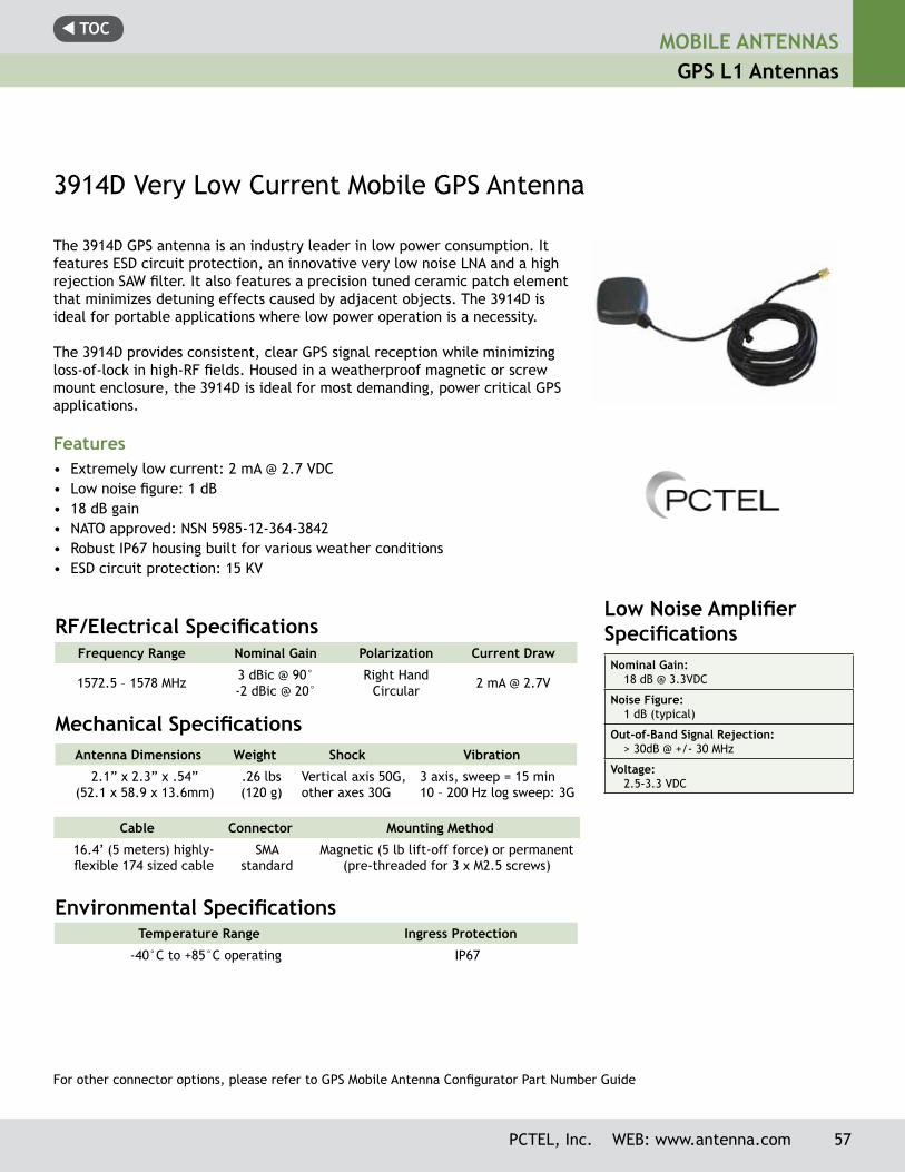
t TOCMOBILE ANTENNAS
GPS L1 Antennas
PCTEL, Inc. WEB: www.antenna.com 57
Low Noise Amplifier SpecificationsNominal Gain:
18 dB @ 3.3VDC
Noise Figure:1 dB (typical)
Out-of-Band Signal Rejection:> 30dB @ +/- 30 MHz
Voltage:2.5-3.3 VDC
3914D Very Low Current Mobile GPS Antenna
The 3914D GPS antenna is an industry leader in low power consumption. It features ESD circuit protection, an innovative very low noise LNA and a high rejection SAW filter. It also features a precision tuned ceramic patch element that minimizes detuning effects caused by adjacent objects. The 3914D is ideal for portable applications where low power operation is a necessity.
The 3914D provides consistent, clear GPS signal reception while minimizing loss-of-lock in high-RF fields. Housed in a weatherproof magnetic or screw mount enclosure, the 3914D is ideal for most demanding, power critical GPS applications.
Features• Extremely low current: 2 mA @ 2.7 VDC• Low noise figure: 1 dB• 18 dB gain • NATO approved: NSN 5985-12-364-3842• Robust IP67 housing built for various weather conditions• ESD circuit protection: 15 KV
Frequency Range Nominal Gain Polarization Current Draw
1572.5 – 1578 MHz 3 dBic @ 90°-2 dBic @ 20°
Right Hand Circular 2 mA @ 2.7V
RF/Electrical Specifications
Antenna Dimensions Weight Shock Vibration
2.1” x 2.3” x .54”(52.1 x 58.9 x 13.6mm)
.26 lbs(120 g)
Vertical axis 50G, other axes 30G
3 axis, sweep = 15 min10 – 200 Hz log sweep: 3G
Mechanical Specifications
Environmental Specifications Temperature Range Ingress Protection
-40°C to +85°C operating IP67
Cable Connector Mounting Method
16.4’ (5 meters) highly-flexible 174 sized cable
SMA standard
Magnetic (5 lb lift-off force) or permanent (pre-threaded for 3 x M2.5 screws)
For other connector options, please refer to GPS Mobile Antenna Configurator Part Number Guide
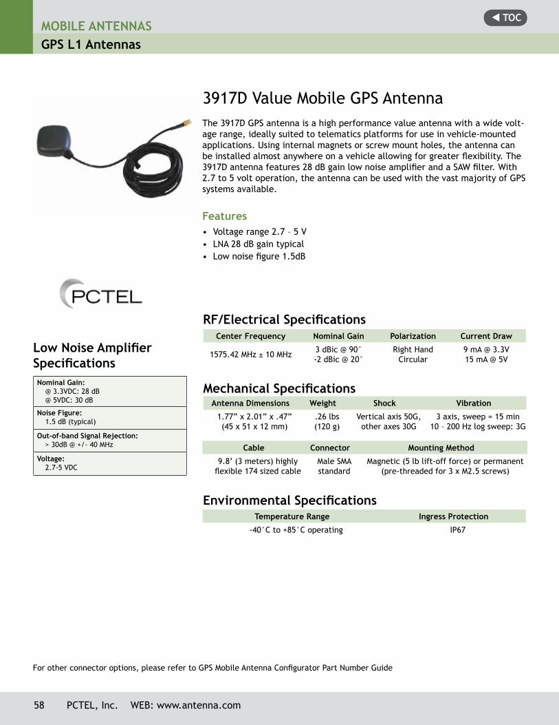
t TOC
3917D Value Mobile GPS AntennaThe 3917D GPS antenna is a high performance value antenna with a wide volt-age range, ideally suited to telematics platforms for use in vehicle-mounted applications. Using internal magnets or screw mount holes, the antenna can be installed almost anywhere on a vehicle allowing for greater flexibility. The 3917D antenna features 28 dB gain low noise amplifier and a SAW filter. With 2.7 to 5 volt operation, the antenna can be used with the vast majority of GPS systems available.
Features• Voltage range 2.7 – 5 V• LNA 28 dB gain typical• Low noise figure 1.5dB
Low Noise Amplifier Specifications Nominal Gain:
@ 3.3VDC: 28 dB @ 5VDC: 30 dB
Noise Figure:1.5 dB (typical)
Out-of-band Signal Rejection:> 30dB @ +/- 40 MHz
Voltage:2.7-5 VDC
Center Frequency Nominal Gain Polarization Current Draw
1575.42 MHz ± 10 MHz 3 dBic @ 90°-2 dBic @ 20°
Right Hand Circular
9 mA @ 3.3V 15 mA @ 5V
RF/Electrical Specifications
Antenna Dimensions Weight Shock Vibration
1.77” x 2.01” x .47” (45 x 51 x 12 mm)
.26 lbs(120 g)
Vertical axis 50G, other axes 30G
3 axis, sweep = 15 min10 – 200 Hz log sweep: 3G
Mechanical Specifications
Environmental Specifications Temperature Range Ingress Protection
-40°C to +85°C operating IP67
Cable Connector Mounting Method
9.8’ (3 meters) highly flexible 174 sized cable
Male SMA standard
Magnetic (5 lb lift-off force) or permanent (pre-threaded for 3 x M2.5 screws)
MOBILE ANTENNASGPS L1 Antennas
58 PCTEL, Inc. WEB: www.antenna.com
For other connector options, please refer to GPS Mobile Antenna Configurator Part Number Guide

t TOCMOBILE ANTENNAS
GPS L1 Multi-band Antennas Parts Number Guide
PCTEL, Inc. WEB: www.antenna.com 59
**
GPS PLUS SERIESGPPB = 26 dB, Permanent, Black
GPPW = 26 dB, Permanent, White
GPMB = 26 dB, Magnetic, Black
GPTB = 26 dB, Trunk, Black
GPRB = 26 dB, Mirror, Black
GPPL = 16 dB, Permanent, Black
GPML = 16 dB, Magnetic, Black
GPRL = 16 dB, Mirror, Black
GPS TRIBAND SERIESGTMU = Low Profile, Magnetic, Black
GTPU = Low Profile, Permanent, Black
GTSU = Sharkfin, Permanent, Black
CABLE LENGTHCable is available in length by inch. Longer cable will lead to higher potential loss. Cable length may not exceed 17 Feet (204 Inches).
ex. 010 = 10 Inches
ex. 150 = 14 ft 6 in. (150 in.)
ex. 200 = 16 ft 8 in. (200 in.)
CONNECTOR COMPATIBILITyConnectors are not necessarily compatible with every cable type. Please inquire to customer service as to what configurations and inventory are available.
PCTEL’s GPS multi-band mobile antennas can be configured with several cable and connector options. Please refer to the template below to determine your configurator part number.
GPS Multi-Band Mobile Antenna Configurator Part Number Guide - Tri-band Models
CONNECTOR TyPE B = BNC
N = N
F = FME
S = SMA
P = PL259
M = Mini-UHF
T = TNC
U = SMB
X = MCX
Z = MMCX
CONNECTOR TyPE 1 = Male
2 = Male reverse polarity
3 = Male right angle
4 = Female
5 = Female reverse polarity
6 = Female right angle
7 = Male soldered
8 = Female soldered
OPTIONAL CONNECTOR ATTACHMENT[Does not appear in every part number]
Connector comes attached unless denoted with an ‘N’ following the connector type
N = Connector Included (not attached)
GPMB - 200 - S1N - N4 Cable Length NMO Mount Connector
GPS Plus Series GPS Connector
16 ft 8 Inches N Female AttachedGPS Plus, Black, SMA Male LoosePermanent, 26 dB
**Product cable length will be within +/- 2 inches of the requested length. The requested length must be equal for both cables.
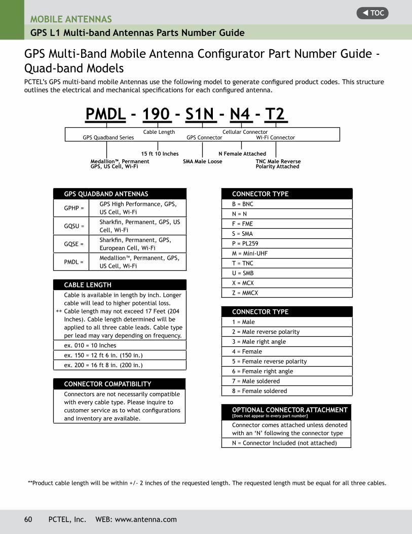
t TOCMOBILE ANTENNASGPS L1 Multi-band Antennas Parts Number Guide
60 PCTEL, Inc. WEB: www.antenna.com
**
GPS QUADBAND ANTENNAS
GPHP = GPS High Performance, GPS, US Cell, Wi-Fi
GQSU = Sharkfin, Permanent, GPS, US Cell, Wi-Fi
GQSE =Sharkfin, Permanent, GPS, European Cell, Wi-Fi
PMDL =Medallion™, Permanent, GPS, US Cell, Wi-Fi
CABLE LENGTHCable is available in length by inch. Longer cable will lead to higher potential loss. Cable length may not exceed 17 Feet (204 Inches). Cable length determined will be applied to all three cable leads. Cable type per lead may vary depending on frequency.
ex. 010 = 10 Inches
ex. 150 = 12 ft 6 in. (150 in.)
ex. 200 = 16 ft 8 in. (200 in.)
CONNECTOR COMPATIBILITyConnectors are not necessarily compatible with every cable type. Please inquire to customer service as to what configurations and inventory are available.
PCTEL’s GPS multi-band mobile Antennas use the following model to generate configured product codes. This structure outlines the electrical and mechanical specifications for each configured antenna.
GPS Multi-Band Mobile Antenna Configurator Part Number Guide - Quad-band Models
CONNECTOR TyPE B = BNC
N = N
F = FME
S = SMA
P = PL259
M = Mini-UHF
T = TNC
U = SMB
X = MCX
Z = MMCX
CONNECTOR TyPE 1 = Male
2 = Male reverse polarity
3 = Male right angle
4 = Female
5 = Female reverse polarity
6 = Female right angle
7 = Male soldered
8 = Female soldered
OPTIONAL CONNECTOR ATTACHMENT[Does not appear in every part number]
Connector comes attached unless denoted with an ‘N’ following the connector type
N = Connector Included (not attached)
PMDL - 190 - S1N - N4 - T2 Cable Length Cellular Connector
GPS Quadband Series GPS Connector Wi-Fi Connector
15 ft 10 Inches N Female AttachedMedallion™, Permanent SMA Male Loose TNC Male ReverseGPS, US Cell, Wi-Fi Polarity Attached
**Product cable length will be within +/- 2 inches of the requested length. The requested length must be equal for all three cables.
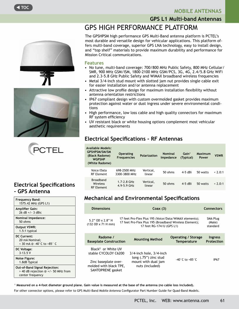
t TOCMOBILE ANTENNAS
GPS L1 Multi-band Antennas
GPS HIGH PERFORMANCE PLATFORMThe GPSHPSM high performance GPS Multi-Band antenna platform is PCTEL’s most durable and versatile design for vehicular applications. This platform of-fers multi-band coverage, superior GPS LNA technology, easy to install design, and “top shelf” materials to provide maximum durability and performance for Mission Critical communications.
Features• No tune, multi-band coverage: 700/800 MHz Public Safety, 800 MHz Cellular/
SMR, 900 MHz GSM/ISM, 1800-2100 MHz GSM/PCS, 3G, 4G, 2.4/5.8 GHz WiFi and 2.3-5.8 GHz Public Safety and WiMAX broadband wireless frequencies
• Metal 3/4-inch stud mount with slotted jam nut provides single cable exit for easier installation and/or antenna replacement
• Attractive low profile design for maximum installation flexibility without antenna orientation restrictions
• IP67 compliant design with custom overmolded gasket provides maximum protection against water or dust ingress under severe environmental condi-tions
• High performance, low loss cable and high quality connectors for maximum RF system efficiency
• UV resistant black or white housing options complement most vehicular aesthetic requirements
Electrical Specifications - GPS AntennaFrequency Band:
1575.42 MHz (GPS L1)
Amplifier Gain:26 dB +/- 3 dBic
Nominal Impedance:50 ohms
Output VSWR:1.5:1 typical
DC Current:20 mA Nominal; < 30 mA @ -40°C to +85° C
DC Voltage:3-13.5 V
Noise Figure:1.8dB Typical
Out-of-Band Signal Rejection:> 40 dB rejection @ +/- 50 MHz from center frequency
Electrical Specifications - RF Antennas
Available Models: GPSHPSM/SM/SM (Black Radome)
WGPSHP (White Radome)
Operating Frequencies Polarization Nominal
ImpedanceGain1
(Typical)Maximum
Power VSWR
Voice/Data RF Element
698-2500 MHz3300-3800 MHz
Vertical, linear 50 ohms 4-5 dBi 50 watts < 2.0:1
Broadband Wireless
RF Element
1.7-2.8 GHz4.9-5.9 GHz
Vertical, linear 50 ohms 4-5 dBi 50 watts < 2.0:1
1 Measured on a 4-foot diameter ground plane. Gain value is measured at the base of the antenna (no cable loss included).
Mechanical and Environmental Specifications
Dimensions Coax (3) Connectors
5.2” OD x 2.8” H(132 OD x 71 H mm)
17 feet Pro-Flex Plus 195 (Voice/Data/WiMAX elements); 17 feet Pro-Flex Plus 195 (Broadband Wireless Element);
17 feet RG-174/U (GPS L1)
SMA Plug (Male)
standard
Radome /Baseplate Construction Mounting Method Operating / Storage
TemperatureIngress
Protection
Black2 or White UV stable CYCOLOY C6200
Zinc baseplate over-molded with black TPE,
SANTOPRENE gasket
3/4-inch hole, 3/4-inch long (.75”) zinc stud mount with dual jam
nuts (included)
-40°C to +85°C IP67
PCTEL, Inc. WEB: www.antenna.com 61
For other connector options, please refer to GPS Multi-Band Mobile Antenna Configurator Part Number Guide for Quad-Band Models.
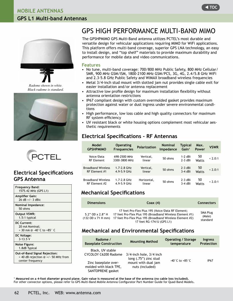
t TOCMOBILE ANTENNASGPS L1 Multi-band Antennas
GPS HIGH PERFORMANCE MULTI-BAND MIMOThe GPSHPMIMO GPS Multi-Band antenna utilizes PCTEL’s most durable and versatile design for vehicular applications requiring MIMO for WiFi applications. This platform offers multi-band coverage, superior GPS LNA technology, an easy to install design, and “top shelf” materials to provide maximum durability and performance for mobile data and video communications.
Features• No tune, multi-band coverage: 700/800 MHz Public Safety, 800 MHz Cellular/
SMR, 900 MHz GSM/ISM, 1800-2100 MHz GSM/PCS, 3G, 4G, 2.4/5.8 GHz WiFi and 2.3-5.8 GHz Public Safety and WiMAX broadband wireless frequencies
• Metal 3/4-inch stud mount with slotted jam nut provides single cable exit for easier installation and/or antenna replacement
• Attractive low profile design for maximum installation flexibility without antenna orientation restrictions
• IP67 compliant design with custom overmolded gasket provides maximum protection against water or dust ingress under severe environmental condi-tions
• High performance, low loss cable and high quality connectors for maximum RF system efficiency
• UV resistant black or white housing options complement most vehicular aes-thetic requirements
Electrical Specifications - RF AntennasModel
GPSHPMIMOOperating
Frequencies Polarization Nominal Impedance
Typical Gain1
Max. Power VSWR
Voice/Data RF Element
698-2500 MHz3300-3800 MHz
Vertical, linear 50 ohms 1-2 dBi
2-3 dBi50
Watts< 2.0:1
Broadband Wireless RF Element #1
1.7-2.8 GHz4.9-5.9 GHz
Vertical, linear 50 ohms 2-3 dBi
3-4 dBi50
Watts< 2.0:1
Broadband Wireless RF Element #2
1.7-2.8 GHz4.9-5.9 GHz
Horizontal, linear 50 ohms 2-3 dBi
3-4 dBi50
Watts< 2.0:1
Mechanical Specifications
Dimensions Coax (4) Connectors
5.2” OD x 2.8” H(132 OD x 71 H mm)
17 feet Pro-Flex Plus 195 (Voice/Data RF Element;17 feet Pro-Flex Plus 195 (Broadband Wireless Element #1) 17 feet Pro-Flex Plus 195 (Broadband Wireless Element #2)
17 feet RG-174/U (GPS L1)
SMA Plug (Male)
standard
Mechanical and Environmental SpecificationsRadome /
Baseplate Construction Mounting Method Operating / Storagetemperature
IngressProtection
Black, UV stableCYCOLOY C6200 Radome
Zinc baseplate over-molded with black TPE,
SANTOPRENE gasket
3/4-inch hole, 3/4 inch long (.75”) zinc stud mount with dual jam
nuts (included)
-40°C to +85°C IP67
Electrical Specifications GPS AntennaFrequency Band:
1575.42 MHz (GPS L1)
Amplifier Gain:26 dB +/- 3 dBic
Nominal Impedance:50 ohms
Output VSWR:1.5:1 typical
DC Current:20 mA Nominal; < 30 mA @ -40°C to +85° C
DC Voltage:3-13.5 V
Noise Figure:1.8dB Typical
Out-of-Band Signal Rejection:> 40 dB rejection @ +/- 50 MHz from center frequency
1 Measured on a 4-foot diameter ground plane. Gain value is measured at the base of the antenna (no cable loss included).
Radome shown in white. Black radome is standard.
62 PCTEL, Inc. WEB: www.antenna.com
For other connector options, please refer to GPS Multi-Band Mobile Antenna Configurator Part Number Guide for Quad-Band Models.
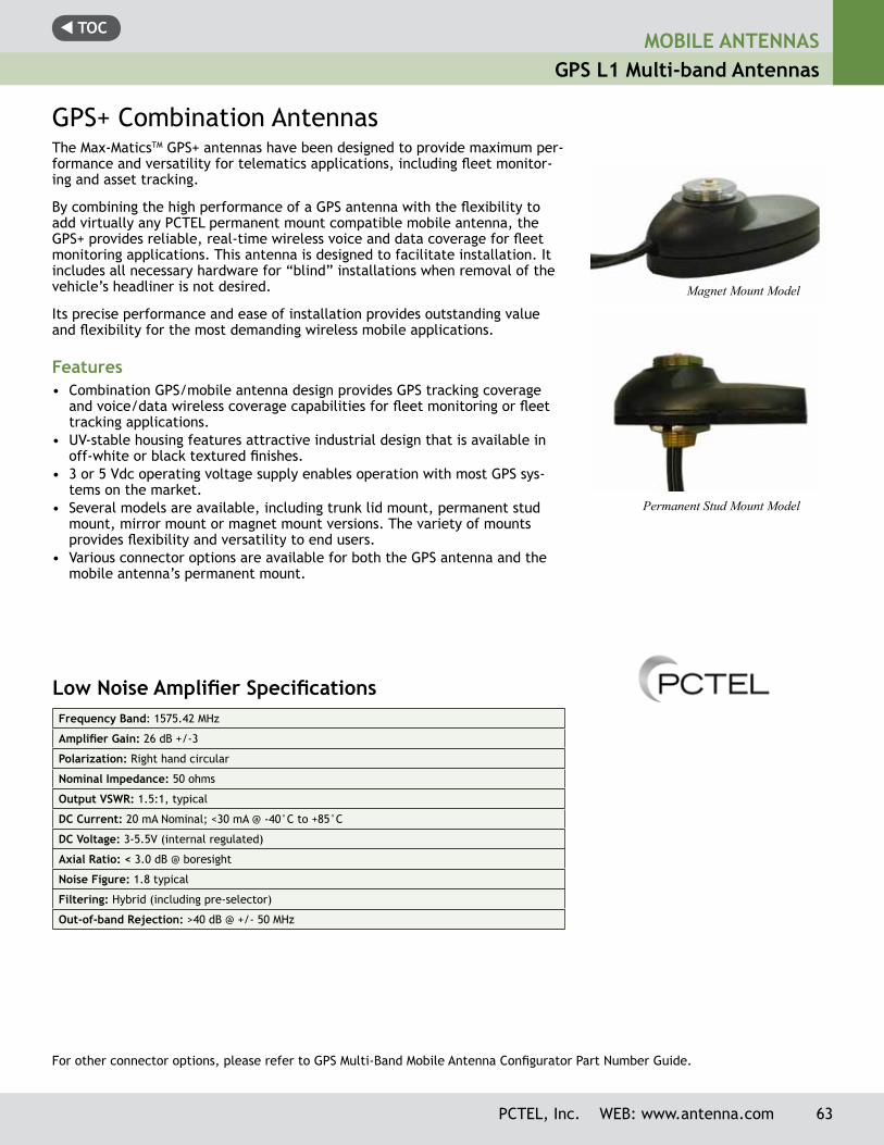
t TOCMOBILE ANTENNAS
GPS L1 Multi-band Antennas
PCTEL, Inc. WEB: www.antenna.com 63
GPS+ Combination AntennasThe Max-MaticsTM GPS+ antennas have been designed to provide maximum per-formance and versatility for telematics applications, including fleet monitor-ing and asset tracking.
By combining the high performance of a GPS antenna with the flexibility to add virtually any PCTEL permanent mount compatible mobile antenna, the GPS+ provides reliable, real-time wireless voice and data coverage for fleet monitoring applications. This antenna is designed to facilitate installation. It includes all necessary hardware for “blind” installations when removal of the vehicle’s headliner is not desired.
Its precise performance and ease of installation provides outstanding value and flexibility for the most demanding wireless mobile applications.
Features• Combination GPS/mobile antenna design provides GPS tracking coverage
and voice/data wireless coverage capabilities for fleet monitoring or fleet tracking applications.
• UV-stable housing features attractive industrial design that is available in off-white or black textured finishes.
• 3 or 5 Vdc operating voltage supply enables operation with most GPS sys-tems on the market.
• Several models are available, including trunk lid mount, permanent stud mount, mirror mount or magnet mount versions. The variety of mounts provides flexibility and versatility to end users.
• Various connector options are available for both the GPS antenna and the mobile antenna’s permanent mount.
Low Noise Amplifier SpecificationsFrequency Band: 1575.42 MHz
Amplifier Gain: 26 dB +/-3
Polarization: Right hand circular
Nominal Impedance: 50 ohms
Output VSWR: 1.5:1, typical
DC Current: 20 mA Nominal; <30 mA @ -40°C to +85°C
DC Voltage: 3-5.5V (internal regulated)
Axial Ratio: < 3.0 dB @ boresight
Noise Figure: 1.8 typical
Filtering: Hybrid (including pre-selector)
Out-of-band Rejection: >40 dB @ +/- 50 MHz
For other connector options, please refer to GPS Multi-Band Mobile Antenna Configurator Part Number Guide.
Magnet Mount Model
Permanent Stud Mount Model
t TOC
64 PCTEL, Inc. WEB: www.antenna.com
MOBILE ANTENNASGPS L1 Multi-band Antennas
Color* Mount type GPS Connector Mobile Antenna Connector
Black
Add the appropriate suffix (choose from the list below) to indicate your choice of
mount:
Specify your GPS connector of choice by adding the connector abbreviation
from the list below to the part number.
Choose among any of the connec-tor options available below for the
BM mounts with RG-58 cable:
GPSPMM (for magnet mount)Male TNC (MC),
Male SMA (MSMA), Male SMC (MSMC)
Male SMA (MSMA), Male N (NM), TNC (C),
Reverse Polarity SMA (MSMARP)
GPSPSM (for stud mount)
Male TNC (MC), Male SMA (MSMA),
MCX, Right angle MMCX plug (RAMMCX),
Right angle SMB plug (RASBP)
Reverse Polarity SMA (MSMARP)Mini-UHF (PL)
BNC (BN)TNC (C)
Male N (NM)Male SMA (MSMA)
Right Angle Male SMA (RAMSMA)
GPSPMR(for mirror mount)Male TNC (MC) Male N (NM)
GPSPTM (for trunk mount)Right angle SMB plug (RASBP) N/C
To order, please follow the following part number configuration:
Burn-out Protection Operating Temperature Range
Storage Temperature Range
Protected from damage by RF signals when the power received by the antenna is no greater than +17 dBm, maximum -40°C to +85°C -40°C to +100°C
Environmental Specifications
Housing Material Housing Dimensions Mobile Antenna Mount Interface Cable Cable Pull
Force Mounting Options
Black or off-white, UV-stable polycarbonate
2.25” W x 4.25” L x 1.25” H
1-1/8”-18 thread mount
17’ RG-174 (GPS antenna side)
17’ RG-58/U (mobile antenna side)
5 kgf, minimum (magnetic mount
models)
Stud, mirror, trunk or magnet
Mechanical Specifications
*White radome is a special order item. Contact Customer Service for details.
For other connector options, please refer to GPS Multi-Band Mobile Antenna Configurator Part Number Guide.
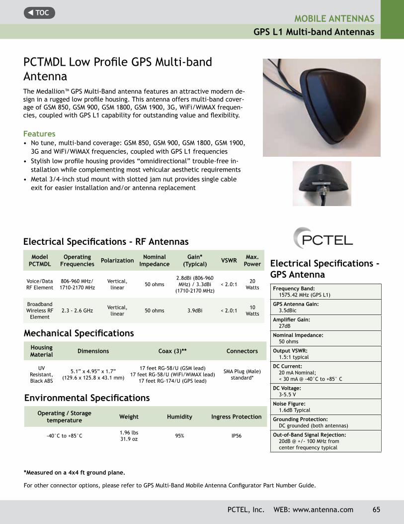
t TOC
PCTEL, Inc. WEB: www.antenna.com 65
MOBILE ANTENNASGPS L1 Multi-band Antennas
PCTMDL Low Profile GPS Multi-band AntennaThe Medallion™ GPS Multi-Band antenna features an attractive modern de-sign in a rugged low profile housing. This antenna offers multi-band cover-age of GSM 850, GSM 900, GSM 1800, GSM 1900, 3G, WiFi/WiMAX frequen-cies, coupled with GPS L1 capability for outstanding value and flexibility.
Features• No tune, multi-band coverage: GSM 850, GSM 900, GSM 1800, GSM 1900,
3G and WiFi/WiMAX frequencies, coupled with GPS L1 frequencies• Stylish low profile housing provides “omnidirectional” trouble-free in-
stallation while complementing most vehicular aesthetic requirements• Metal 3/4-inch stud mount with slotted jam nut provides single cable
exit for easier installation and/or antenna replacement
Electrical Specifications - RF AntennasModel
PCTMDLOperating
Frequencies Polarization Nominal Impedance
Gain* (Typical) VSWR Max.
Power
Voice/Data RF Element
806-960 MHz/1710-2170 MHz
Vertical, linear 50 ohms
2.8dBi (806-960 MHz) / 3.3dBi
(1710-2170 MHz)< 2.0:1 20
Watts
Broadband Wireless RF
Element2.3 - 2.6 GHz Vertical,
linear 50 ohms 3.9dBi < 2.0:1 10 Watts
*Measured on a 4x4 ft ground plane.
Mechanical SpecificationsHousing Material Dimensions Coax (3)** Connectors
UVResistant, Black ABS
5.1” x 4.95” x 1.7”(129.6 x 125.8 x 43.1 mm)
17 feet RG-58/U (GSM lead)17 feet RG-58/U (WiFi/WiMAX lead)
17 feet RG-174/U (GPS lead)
SMA Plug (Male) standard*
Environmental SpecificationsOperating / Storage
temperature Weight Humidity Ingress Protection
-40°C to +85°C 1.96 lbs31.9 oz 95% IP56
Electrical Specifications - GPS AntennaFrequency Band:
1575.42 MHz (GPS L1)
GPS Antenna Gain:3.5dBic
Amplifier Gain:27dB
Nominal Impedance:50 ohms
Output VSWR:1.5:1 typical
DC Current:20 mA Nominal; < 30 mA @ -40°C to +85° C
DC Voltage:3-5.5 V
Noise Figure:1.6dB Typical
Grounding Protection:DC grounded (both antennas)
Out-of-Band Signal Rejection:20dB @ +/- 100 MHz from center frequency typical
For other connector options, please refer to GPS Multi-Band Mobile Antenna Configurator Part Number Guide.
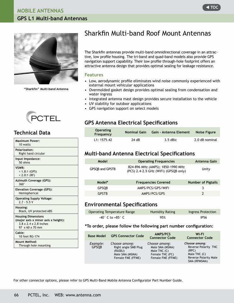
t TOCMOBILE ANTENNASGPS L1 Multi-band Antennas
66 PCTEL, Inc. WEB: www.antenna.com
“Sharkfin” Multi-band Antenna
Technical Data Maximum Power:
10 watts
Polarization:Right hand circular
Input Impedance:50 ohms
VSWR:< 1.8:1 (GPS)< 2.0:1 (RF)
Azimuth Coverage (GPS):360°
Elevation Coverage (GPS):Hemispherical
Operating Supply Voltage:2.7 - 5.5 V
Housing:Black, UV protected ABS
Housing Dimensions (major axis x minor axis x height):
3.8 x 2.4 x 2.8 inches97 x 60 x 70 mm
Cable:10 feet RG-174
Mount Method:Through hole mounting
The Sharkfin antennas provide multi-band omnidirectional coverage in an attrac-tive, low profile housing. The tri-band and quad-band models also provide GPS navigation support capability. Their low profile through-hole footprint offers an attractive antenna design that provides optimal sealing for leakage resistance.
Features• Low, aerodynamic profile eliminates wind noise commonly experienced with
external mount vehicular applications• Overmolded gasket design provides optimal sealing from condensation and
water ingress• Integrated antenna mast design provides secure installation to the vehicle• UV stability for outdoor applications• GPS navigation support on select models
Model* Frequencies Covered Number of Pigtails
GPSQB AMPS/PCS/GPS/WiFi 3
GPSTB AMPS/PCS/GPS 2
Sharkfin Multi-band Roof Mount Antennas
Operating Frequency Nominal Gain Gain - Antenna Element Noise Figure
L1: 1575.42 24 dB 3.5 dBic 2.0 dB nominal
Model Operating Frequencies Antenna Gain
GPSQB and GPSTB 824-896 MHz (AMPS); 1850-1990 MHz (PCS) 2.4-2.5 GHz (WiFi) (GPSQB only) Unity
Operating Temperature Range Humidity Rating Ingress Protection
-40° C to +85° C 95% IP56
GPS Antenna Electrical Specifications
Environmental Specifications
Multi-band Antenna Electrical Specifications
Base Model GPS Connector Code AMPS/PCS Connector Code
Wi-Fi Connector Code
Example:GPSQB
Choose among:Right angle SMB Plug (RASBJ)Male SMA (MSMA)Female FME (FFME)
Choose among:Male SMA (MSMA)Male TNC (C)Female TNC (FC)Female FME (FFME)
Choose among: Reverse Polarity TNC (RPC) Male TNC (C) Reverse Polarity Male SMA (RPMSMA)
*To order, please follow the following part number configuration:
For other connector options, please refer to GPS Multi-Band Mobile Antenna Configurator Part Number Guide.
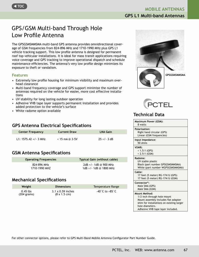
t TOCMOBILE ANTENNAS
GPS L1 Multi-band Antennas
The GPSGSMSMMSMA multi-band GPS antenna provides omnidirectional cover-age of GSM frequencies from 824-896 MHz and 1710-1990 MHz plus GPS L1 vehicle tracking support. This low profile antenna is designed for permanent roof top vehicular installations. It is ideal for mass transit applications requiring voice coverage and GPS tracking to improve operational dispatch and schedule maintenance efficiencies. The antenna’s very low profile design minimizes its exposure to theft or vandalism.
Features• Extremely low profile housing for minimum visibility and maximum over-
head clearance• Multi-band frequency coverage and GPS support minimize the number of
antennas required on the vehicle for easier, more cost effective installa-tions
• UV stability for long lasting outdoor operation• Adhesive VHB tape layer supports permanent installation and provides
added protection to the vehicle’s surface• White radome option available
Weight Dimensions Temperature Range
0.45 lbs(204 grams)
3.1 x 0.59 inches(8 x 1.5 cm)
-40°C to +85°C
GPS/GSM Multi-band Through Hole Low Profile Antenna
Center Frequency Current Draw LNA Gain
L1: 1575.42 +/- 3 MHz < 15 mA @ 3-5V 25 +/- 3 dB
Operating Frequencies Typical Gain (without cable)
824-896 MHz1710-1990 MHZ
2dB +/- 1dB @ 900 MHz1dB +/- 1dB @ 1800 MHz
GPS Antenna Electrical Specifications
GSM Antenna Specifications
Mechanical Specifications
GPSGSMSMMSMA
Technical Data Maximum Power (GSM):
8 watts
Polarization:Right hand circular (GPS)Linear (GSM frequencies)
Input Impedance:50 ohms
VSWR:< 1.5:1 (GPS)< 2.5:1 (GSM)
Radome:UV stable plasticBlack (part number GPSGSMSMMSMA)White (part number WGPSGSMSMMSMA)
Cable:17 feet (5 meter) RG-174/U (GPS)17 feet (5 meter) RG-174/U (GSM)
Connector*:Male SMA (GPS)Male SMA (GSM)
Mount Method:1/2 inch through hole mountMount assembly includes flat adapter shim for installations on existing larger hole diameters.Adhesive VHB tape layer included.
PCTEL, Inc. WEB: www.antenna.com 67
For other connector options, please refer to GPS Multi-Band Mobile Antenna Configurator Part Number Guide.
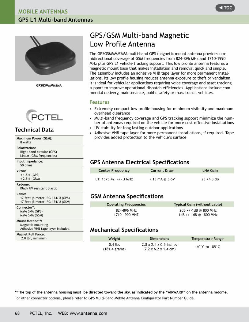
t TOCMOBILE ANTENNASGPS L1 Multi-band Antennas
68 PCTEL, Inc. WEB: www.antenna.com
Technical Data Maximum Power (GSM):
8 watts
Polarization:Right hand circular (GPS)Linear (GSM frequencies)
Input Impedance:50 ohms
VSWR:< 1.5:1 (GPS)< 2.5:1 (GSM)
Radome:Black UV resistant plastic
Cable:17 feet (5 meter) RG-174/U (GPS)17 feet (5 meter) RG-174/U (GSM)
Connector*:Male SMA (GPS)Male SMA (GSM)
Mount Method**:Magnetic mountingAdhesive VHB tape layer included.
Magnet Pull Force: 2.8 lbf, minimum
GPSGSMMMMSMA
The GPSGSMMMMSMA multi-band GPS magnetic mount antenna provides om-nidirectional coverage of GSM frequencies from 824-896 MHz and 1710-1990 MHz plus GPS L1 vehicle tracking support. This low profile antenna features a magnetic mount base that makes installation and removal quick and simple. The assembly includes an adhesive VHB tape layer for more permanent instal-lations. Its low profile housing reduces antenna exposure to theft or vandalism. It is ideal for vehicular applications requiring voice coverage and asset tracking support to improve operational dispatch efficiencies. Applications include com-mercial delivery, maintenance, public safety or mass transit vehicles.
Features• Extremely compact low profile housing for minimum visibility and maximum
overhead clearance• Multi-band frequency coverage and GPS tracking support minimize the num-
ber of antennas required on the vehicle for more cost effective installations• UV stability for long lasting outdoor applications• Adhesive VHB tape layer for more permanent installations, if required. Tape
provides added protection to the vehicle’s surface
Weight Dimensions Temperature Range
0.4 lbs(181.4 grams)
2.8 x 2.4 x 0.5 inches(7.2 x 6.2 x 1.4 cm) -40°C to +85°C
GPS/GSM Multi-band Magnetic Low Profile Antenna
Mechanical Specifications
Center Frequency Current Draw LNA Gain
L1: 1575.42 +/- 3 MHz < 15 mA @ 3-5V 25 +/-3 dB
Operating Frequencies Typical Gain (without cable)
824-896 MHz1710-1990 MHZ
2dB +/-1dB @ 800 MHz1dB +/-1dB @ 1800 MHz
GPS Antenna Electrical Specifications
GSM Antenna Specifications
** The top of the antenna housing must be directed toward the sky, as indicated by the “AIRWARD” on the antenna radome.
For other connector options, please refer to GPS Multi-Band Mobile Antenna Configurator Part Number Guide.
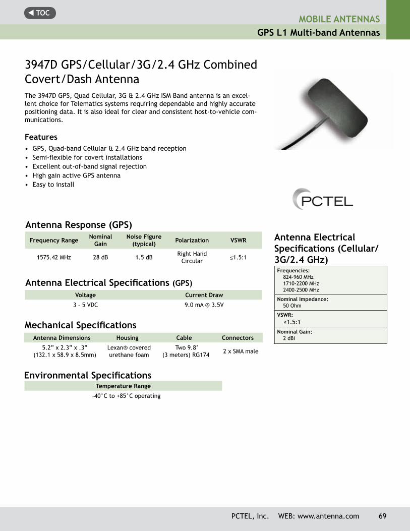
t TOC
PCTEL, Inc. WEB: www.antenna.com 69
MOBILE ANTENNASGPS L1 Multi-band Antennas
3947D GPS/Cellular/3G/2.4 GHz Combined Covert/Dash AntennaThe 3947D GPS, Quad Cellular, 3G & 2.4 GHz ISM Band antenna is an excel-lent choice for Telematics systems requiring dependable and highly accurate positioning data. It is also ideal for clear and consistent host-to-vehicle com-munications.
Features• GPS, Quad-band Cellular & 2.4 GHz band reception• Semi-flexible for covert installations• Excellent out-of-band signal rejection• High gain active GPS antenna• Easy to install
Antenna Electrical Specifications (GPS)
Antenna Dimensions Housing Cable Connectors
5.2” x 2.3” x .3” (132.1 x 58.9 x 8.5mm)
Lexan® covered urethane foam
Two 9.8’ (3 meters) RG174 2 x SMA male
Mechanical Specifications
Environmental Specifications Temperature Range
-40°C to +85°C operating
Voltage Current Draw
3 – 5 VDC 9.0 mA @ 3.5V
Frequency Range NominalGain
Noise Figure (typical) Polarization VSWR
1575.42 MHz 28 dB 1.5 dB Right Hand Circular ≤1.5:1
Antenna Response (GPS)Antenna Electrical Specifications (Cellular/ 3G/2.4 GHz)Frequencies:
824-960 MHz1710-2200 MHz 2400-2500 MHz
Nominal Impedance:50 Ohm
VSWR: ≤1.5:1
Nominal Gain:2 dBi
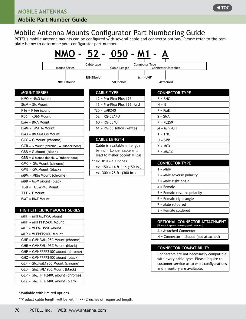
t TOCMOBILE ANTENNASMobile Part Number Guide
70 PCTEL, Inc. WEB: www.antenna.com
CONNECTOR TyPE B = BNC
N = N
F = FME
S = SMA
P = PL259
M = Mini-UHF
T = TNC
U = SMB
X = MCX
Z = MMCX
CONNECTOR TyPE 1 = Male
2 = Male reverse polarity
3 = Male right angle
4 = Female
5 = Female reverse polarity
6 = Female right angle
7 = Male soldered
8 = Female soldered
OPTIONAL CONNECTOR ATTACHMENT[Does not appear in every part number]
A = Attached Connector
N = Connector Included (not attached)
CONNECTOR COMPATIBILITyConnectors are not necessarily compatible with every cable type. Please inquire to customer service as to what configurations and inventory are available.
**
PCTEL’s mobile antenna mounts can be configured with several cable and connector options. Please refer to the tem-plate below to determine your configurator part number.
Mobile Antenna Mounts Configurator Part Numbering Guide
MOUNT SERIESNMO = NMO Mount
SMM = SM Mount
K16 = K166 Mount
KD6 = KD66 Mount
BMA = BMA Mount
BMM = BMATM Mount
BM3 = BMATM338 Mount
GCC = G Mount (chrome)
GCR = G Mount (chrome, w/rubber boot)
GBB = G Mount (black)
GBR = G Mount (black, w/rubber boot)
GMC = GM Mount (chrome)
GMB = GM Mount (black)
MBM = MBM Mount (chrome)
MBB = MBM Mount (black)
TGB = TGBWP45 Mount
TTT = T Mount
BMT = BMT Mount
HIGH EFFICIENCy MOUNT SERIESMHF = MHFML195C Mount
MHP = MHFPFP240C Mount
MLF = MLFML195C Mount
MLP = MLFPFP240C Mount
GHF = GMHFML195C Mount (chrome)
GHB = GMHFML195C Mount (black)
GHP = GMHFPFP240C Mount (chrome)
GHZ = GMHFPFP240C Mount (black)
GLF = GMLFML195C Mount (chrome)
GLB = GMLFML195C Mount (black)
GLP = GMLFPFP240C Mount (chrome)
GLZ = GMLFPFP240C Mount (black)
CABLE TyPE12 = Pro-Flex Plus 195
13 = Pro-Flex Plus 195, A/U
*20 = LMR240
52 = RG-58A/U
60 = RG-58/U
61 = RG-58 Teflon (white)
CABLE LENGTHCable is available in length by inch. Longer cable will lead to higher potential loss.
ex. 010 = 10 Inches
ex. 150 = 14 ft 6 in (150 in.)
ex. 300 = 25 ft. (300 in.)
NMO - 52 - 050 - M1 - A Cable type Connector Type
Mount Series Cable Length Connector Attached
RG-58A/U Mini-UHFNMO Mount 50 Inches Attached
**Product cable length will be within +/- 2 inches of requested length.
*Available with limited options
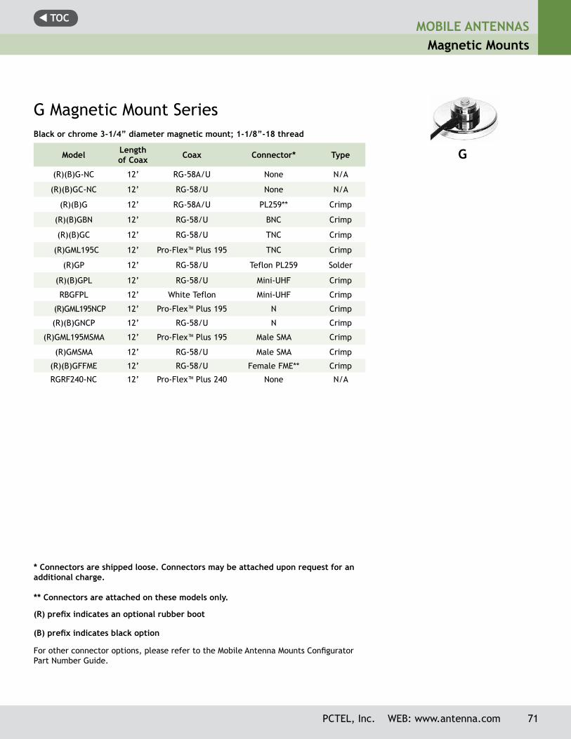
t TOC
PCTEL, Inc. WEB: www.antenna.com 71
MOBILE ANTENNASMagnetic Mounts
Black or chrome 3-1/4” diameter magnetic mount; 1-1/8”-18 thread
Model Length of Coax Coax Connector* Type
(R)(B)G-NC 12’ RG-58A/U None N/A
(R)(B)GC-NC 12’ RG-58/U None N/A
(R)(B)G 12’ RG-58A/U PL259** Crimp
(R)(B)GBN 12’ RG-58/U BNC Crimp
(R)(B)GC 12’ RG-58/U TNC Crimp
(R)GML195C 12’ Pro-Flex™ Plus 195 TNC Crimp
(R)GP 12’ RG-58/U Teflon PL259 Solder
(R)(B)GPL 12’ RG-58/U Mini-UHF Crimp
RBGFPL 12’ White Teflon Mini-UHF Crimp
(R)GML195NCP 12’ Pro-Flex™ Plus 195 N Crimp
(R)(B)GNCP 12’ RG-58/U N Crimp
(R)GML195MSMA 12’ Pro-Flex™ Plus 195 Male SMA Crimp
(R)GMSMA 12’ RG-58/U Male SMA Crimp
(R)(B)GFFME 12’ RG-58/U Female FME** Crimp
RGRF240-NC 12’ Pro-Flex™ Plus 240 None N/A
G Magnetic Mount Series
* Connectors are shipped loose. Connectors may be attached upon request for an additional charge.
** Connectors are attached on these models only.
(B) prefix indicates black option
(R) prefix indicates an optional rubber boot
G
For other connector options, please refer to the Mobile Antenna Mounts Configurator Part Number Guide.
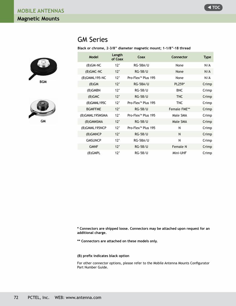
t TOCMOBILE ANTENNASMagnetic Mounts
72 PCTEL, Inc. WEB: www.antenna.com
Black or chrome, 2-3/8” diameter magnetic mount; 1-1/8”-18 thread
Model Length of Coax Coax Connector Type
(B)GM-NC 12’ RG-58A/U None N/A
(B)GMC-NC 12’ RG-58/U None N/A
(B)GMML195-NC 12’ Pro-Flex™ Plus 195 None N/A
(B)GM 12’ RG-58A/U PL259* Crimp
(B)GMBN 12’ RG-58/U BNC Crimp
(B)GMC 12’ RG-58/U TNC Crimp
(B)GMML195C 12’ Pro-Flex™ Plus 195 TNC Crimp
BGMFFME 12’ RG-58/U Female FME** Crimp
(B)GMML195MSMA 12’ Pro-Flex™ Plus 195 Male SMA Crimp
(B)GMMSMA 12’ RG-58/U Male SMA Crimp
(B)GMML195NCP 12’ Pro-Flex™ Plus 195 N Crimp
(B)GMNCP 12’ RG-58/U N Crimp
GMSUNCP 12’ RG-58A/U N Crimp
GMNF 12’ RG-58/U Female N Crimp
(B)GMPL 12’ RG-58/U Mini-UHF Crimp
GM Series
For other connector options, please refer to the Mobile Antenna Mounts Configurator Part Number Guide.
* Connectors are shipped loose. Connectors may be attached upon request for an additional charge.
** Connectors are attached on these models only.
(B) prefix indicates black option
GM
BGM
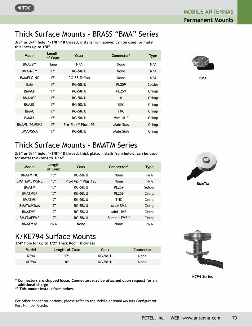
t TOCMOBILE ANTENNASPermanent Mounts
PCTEL, Inc. WEB: www.antenna.com 73
Thick Surface Mounts - BRASS “BMA” Series
Model Length of Coax Coax Connector* Type
BMA38** None N/A None N/A
BMA-NC** 17’ RG-58/U None N/A
BMAFLC-NC 17’ RG-58 Teflon None N/A
BMA 17’ RG-58/U PL259 Solder
BMACP 17’ RG-58/U PL259 Crimp
BMANCP 17’ RG-58/U N Crimp
BMABN 17’ RG-58/U BNC Crimp
BMAC 17’ RG-58/U TNC Crimp
BMAPL 17’ RG-58/U Mini-UHF Crimp
BMAML195MSMA 17’ Pro-Flex™ Plus 195 Male SMA Crimp
BMAMSMA 17’ RG-58/U Male SMA Crimp
3/8” or 3/4” hole; 1-1/8”-18 thread; installs from above; can be used for metal thickness up to 1/8”
* Connectors are shipped loose. Connectors may be attached upon request for an additional charge
** This mount installs from below.
BMA
Thick Surface Mounts - BMATM Series
K/KE794 Surface Mounts
Model Length of Coax Coax Connector* Type
BMATM-NC 17’ RG-58/U None N/A
BMATMML195NC 17’ Pro-Flex™ Plus 195 None N/A
BMATM 17’ RG-58/U PL259 Solder
BMATMCP 17’ RG-58/U PL259 Crimp
BMATMC 17’ RG-58/U TNC Crimp
BMATMMSMA 17’ RG-58/U Male SMA Crimp
BMATMPL 17’ RG-58/U Mini-UHF Crimp
BMATMFFME 17’ RG-58/U Female FME** Crimp
BMATM38 N/A None None N/A
Model Length of Coax Coax Connector
K794 17’ RG-58/U None
KE794 30’ RG-58/U None
3/8” or 3/4” hole; 1-1/8”-18 thread; thick plate; installs from below; can be used for metal thickness to 3/16”
3/4” hole for up to 1/2” Thick Roof Thickness
BMATM
K794 Series
For other connector options, please refer to the Mobile Antenna Mounts Configurator Part Number Guide.
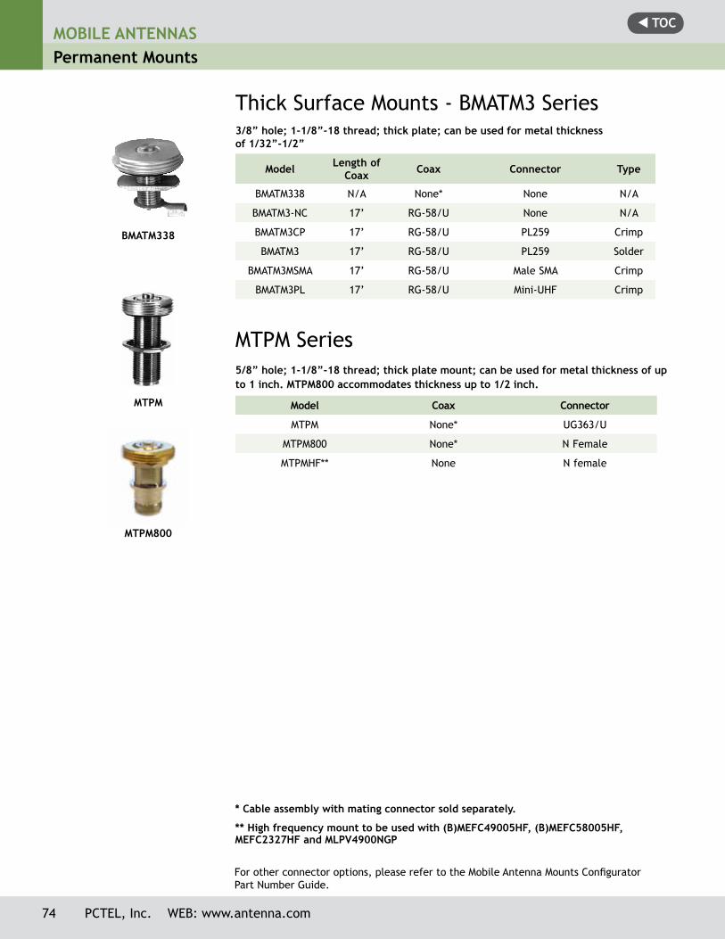
t TOCMOBILE ANTENNASPermanent Mounts
74 PCTEL, Inc. WEB: www.antenna.com
BMATM338
MTPM
MTPM800
3/8” hole; 1-1/8”-18 thread; thick plate; can be used for metal thickness of 1/32”-1/2”
Model Length of Coax Coax Connector Type
BMATM338 N/A None* None N/A
BMATM3-NC 17’ RG-58/U None N/A
BMATM3CP 17’ RG-58/U PL259 Crimp
BMATM3 17’ RG-58/U PL259 Solder
BMATM3MSMA 17’ RG-58/U Male SMA Crimp
BMATM3PL 17’ RG-58/U Mini-UHF Crimp
MTPM Series5/8” hole; 1-1/8”-18 thread; thick plate mount; can be used for metal thickness of up to 1 inch. MTPM800 accommodates thickness up to 1/2 inch.
Model Coax Connector
MTPM None* UG363/U
MTPM800 None* N Female
MTPMHF** None N female
Thick Surface Mounts - BMATM3 Series
* Cable assembly with mating connector sold separately.
** High frequency mount to be used with (B)MEFC49005HF, (B)MEFC58005HF, MEFC2327HF and MLPV4900NGP
For other connector options, please refer to the Mobile Antenna Mounts Configurator Part Number Guide.
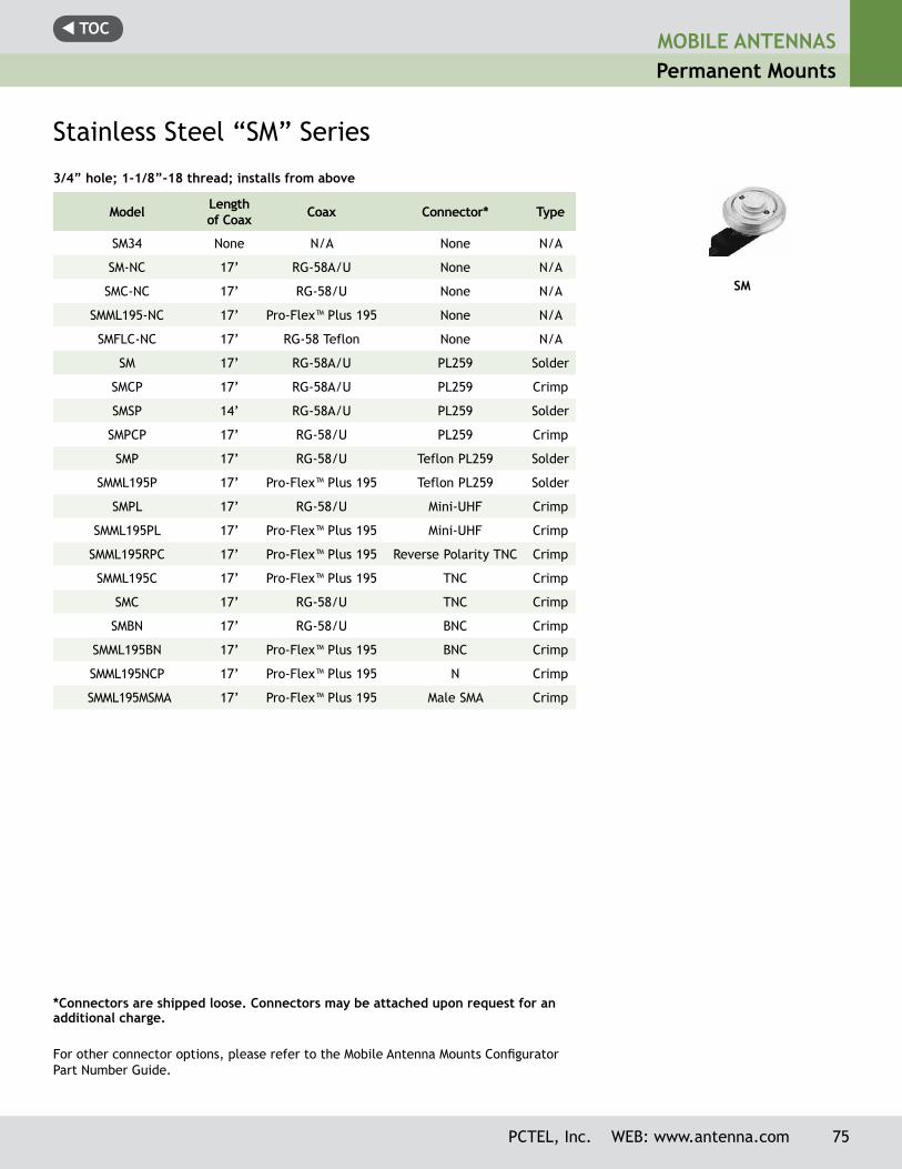
t TOCMOBILE ANTENNASPermanent Mounts
PCTEL, Inc. WEB: www.antenna.com 75
*Connectors are shipped loose. Connectors may be attached upon request for an additional charge.
3/4” hole; 1-1/8”-18 thread; installs from above
Model Length of Coax Coax Connector* Type
SM34 None N/A None N/A
SM-NC 17’ RG-58A/U None N/A
SMC-NC 17’ RG-58/U None N/A
SMML195-NC 17’ Pro-Flex™ Plus 195 None N/A
SMFLC-NC 17’ RG-58 Teflon None N/A
SM 17’ RG-58A/U PL259 Solder
SMCP 17’ RG-58A/U PL259 Crimp
SMSP 14’ RG-58A/U PL259 Solder
SMPCP 17’ RG-58/U PL259 Crimp
SMP 17’ RG-58/U Teflon PL259 Solder
SMML195P 17’ Pro-Flex™ Plus 195 Teflon PL259 Solder
SMPL 17’ RG-58/U Mini-UHF Crimp
SMML195PL 17’ Pro-Flex™ Plus 195 Mini-UHF Crimp
SMML195RPC 17’ Pro-Flex™ Plus 195 Reverse Polarity TNC Crimp
SMML195C 17’ Pro-Flex™ Plus 195 TNC Crimp
SMC 17’ RG-58/U TNC Crimp
SMBN 17’ RG-58/U BNC Crimp
SMML195BN 17’ Pro-Flex™ Plus 195 BNC Crimp
SMML195NCP 17’ Pro-Flex™ Plus 195 N Crimp
SMML195MSMA 17’ Pro-Flex™ Plus 195 Male SMA Crimp
Stainless Steel “SM” Series
SM
For other connector options, please refer to the Mobile Antenna Mounts Configurator Part Number Guide.
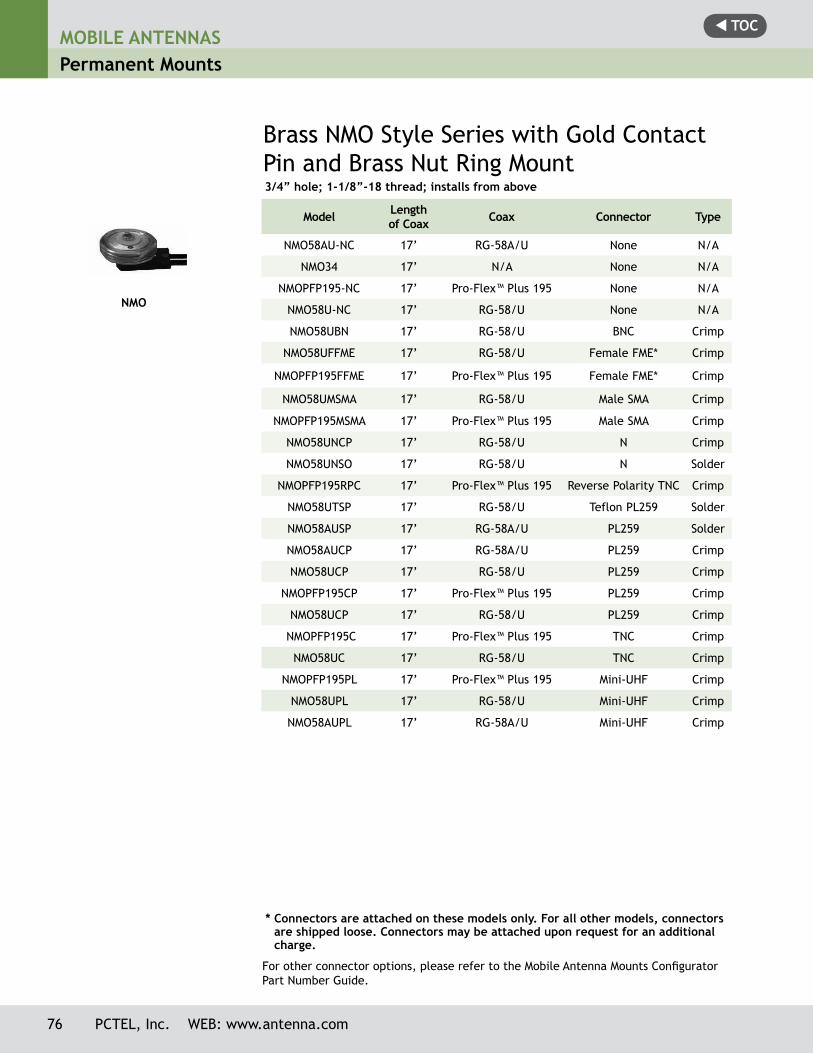
t TOCMOBILE ANTENNASPermanent Mounts
76 PCTEL, Inc. WEB: www.antenna.com
NMO
Brass NMO Style Series with Gold Contact Pin and Brass Nut Ring Mount
Model Length of Coax Coax Connector Type
NMO58AU-NC 17’ RG-58A/U None N/A
NMO34 17’ N/A None N/A
NMOPFP195-NC 17’ Pro-Flex™ Plus 195 None N/A
NMO58U-NC 17’ RG-58/U None N/A
NMO58UBN 17’ RG-58/U BNC Crimp
NMO58UFFME 17’ RG-58/U Female FME* Crimp
NMOPFP195FFME 17’ Pro-Flex™ Plus 195 Female FME* Crimp
NMO58UMSMA 17’ RG-58/U Male SMA Crimp
NMOPFP195MSMA 17’ Pro-Flex™ Plus 195 Male SMA Crimp
NMO58UNCP 17’ RG-58/U N Crimp
NMO58UNSO 17’ RG-58/U N Solder
NMOPFP195RPC 17’ Pro-Flex™ Plus 195 Reverse Polarity TNC Crimp
NMO58UTSP 17’ RG-58/U Teflon PL259 Solder
NMO58AUSP 17’ RG-58A/U PL259 Solder
NMO58AUCP 17’ RG-58A/U PL259 Crimp
NMO58UCP 17’ RG-58/U PL259 Crimp
NMOPFP195CP 17’ Pro-Flex™ Plus 195 PL259 Crimp
NMO58UCP 17’ RG-58/U PL259 Crimp
NMOPFP195C 17’ Pro-Flex™ Plus 195 TNC Crimp
NMO58UC 17’ RG-58/U TNC Crimp
NMOPFP195PL 17’ Pro-Flex™ Plus 195 Mini-UHF Crimp
NMO58UPL 17’ RG-58/U Mini-UHF Crimp
NMO58AUPL 17’ RG-58A/U Mini-UHF Crimp
* Connectors are attached on these models only. For all other models, connectors are shipped loose. Connectors may be attached upon request for an additional charge.
3/4” hole; 1-1/8”-18 thread; installs from above
For other connector options, please refer to the Mobile Antenna Mounts Configurator Part Number Guide.
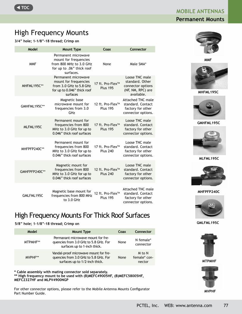
t TOCMOBILE ANTENNASPermanent Mounts
PCTEL, Inc. WEB: www.antenna.com 77
* Cable assembly with mating connector sold separately.** High frequency mount to be used with (B)MEFC49005HF, (B)MEFC58005HF, MEFC2327HF and MLPV4900NGP
High Frequency Mounts3/4” hole; 1-1/8”-18 thread; Crimp on
Model Mount Type Coax Connector
MMF
Permanent microwave mount for frequencies
from 800 MHz to 3.0 GHz for up to .06” thick roof
surfaces.
None Male SMA*
MHFML195C**
Permanent microwave mount for frequencies
from 3.0 GHz to 5.8 GHz for up to 0.046” thick roof
surfaces
17 ft. Pro-FlexTM Plus 195
Loose TNC male standard. Other
connector options (NF, NM, RPC) are
available.
GMHFML195C**
Magnetic base microwave mount for frequencies from 3.0
GHz
12 ft. Pro-FlexTM Plus 195
Attached TNC male standard. Contact factory for other
connector options.
MLFML195C
Permanent mount for frequencies from 800
MHz to 3.0 GHz for up to 0.046” thick roof surfaces
17 ft. Pro-FlexTM Plus 195
Loose TNC male standard. Contact factory for other
connector options.
MHFPFP240C**
Permanent mount for frequencies from 800
MHz to 3.0 GHz for up to 0.046” thick roof surfaces
17 ft. Pro-FlexTM Plus 240
Loose TNC male standard. Contact factory for other
connector options.
GMHFPFP240C**
Magnetic mount for frequencies from 800
MHz to 3.0 GHz for up to 0.046” thick roof surfaces
12 ft. Pro-FlexTM Plus 240
Loose TNC male standard. Contact factory for other
connector options.
GMLFML195CMagnetic base mount for frequencies from 800 MHz
to 3.0 GHz
12 ft. Pro-FlexTM Plus 195
Attached TNC male standard. Contact factory for other
connector options.
High Frequency Mounts For Thick Roof Surfaces5/8” hole; 1-1/8”-18 thread; Crimp on
Model Mount Type Coax Connector
MTPMHF**Permanant microwave mount for fre-quencies from 3.0 GHz to 5.8 GHz. For
surfaces up to 1-inch thick.None N female*
connector
MVPHF**Vandal-proof microwave mount for fre-quencies from 3.0 GHz to 5.8 GHz. For
surfaces up to 1/2-inch thick.None
M to N female* con-
nector
MMF
MHFML195C
MLFML195C
GMLFML195C
GMHFML195C
MVPHF
MHFPFP240C
MTPMHF
For other connector options, please refer to the Mobile Antenna Mounts Configurator Part Number Guide.
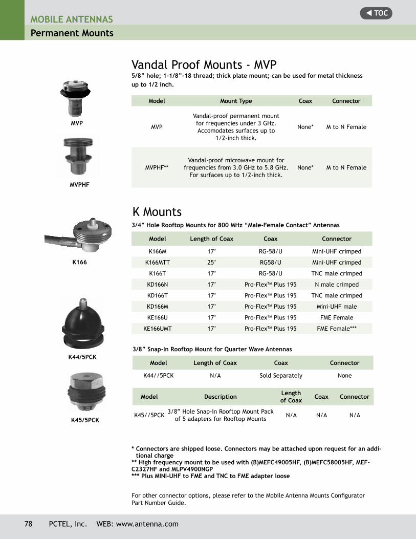
t TOC
78 PCTEL, Inc. WEB: www.antenna.com
MOBILE ANTENNASPermanent Mounts
3/4” Hole Rooftop Mounts for 800 MHz “Male-Female Contact” Antennas
Model Length of Coax Coax Connector
K166M 17’ RG-58/U Mini-UHF crimped
K166MTT 25’ RG58/U Mini-UHF crimped
K166T 17’ RG-58/U TNC male crimped
KD166N 17’ Pro-FlexTM Plus 195 N male crimped
KD166T 17’ Pro-FlexTM Plus 195 TNC male crimped
KD166M 17’ Pro-FlexTM Plus 195 Mini-UHF male
KE166U 17’ Pro-FlexTM Plus 195 FME Female
KE166UMT 17’ Pro-FlexTM Plus 195 FME Female***
K Mounts
3/8” Snap-In Rooftop Mount for Quarter Wave Antennas
Model Length of Coax Coax Connector
K44//5PCK N/A Sold Separately None
Model Description Length of Coax Coax Connector
K45//5PCK 3/8” Hole Snap-In Rooftop Mount Pack of 5 adapters for Rooftop Mounts N/A N/A N/A
* Connectors are shipped loose. Connectors may be attached upon request for an addi-tional charge
** High frequency mount to be used with (B)MEFC49005HF, (B)MEFC58005HF, MEF-C2327HF and MLPV4900NGP*** Plus MINI-UHF to FME and TNC to FME adapter loose
Model Mount Type Coax Connector
MVP
Vandal-proof permanent mount for frequencies under 3 GHz. Accomodates surfaces up to
1/2-inch thick.
None* M to N Female
MVPHF**Vandal-proof microwave mount for
frequencies from 3.0 GHz to 5.8 GHz. For surfaces up to 1/2-inch thick.
None* M to N Female
Vandal Proof Mounts - MVP5/8” hole; 1-1/8”-18 thread; thick plate mount; can be used for metal thickness up to 1/2 inch.
For other connector options, please refer to the Mobile Antenna Mounts Configurator Part Number Guide.
K166
K44/5PCK
K45/5PCK
MVP
MVPHF
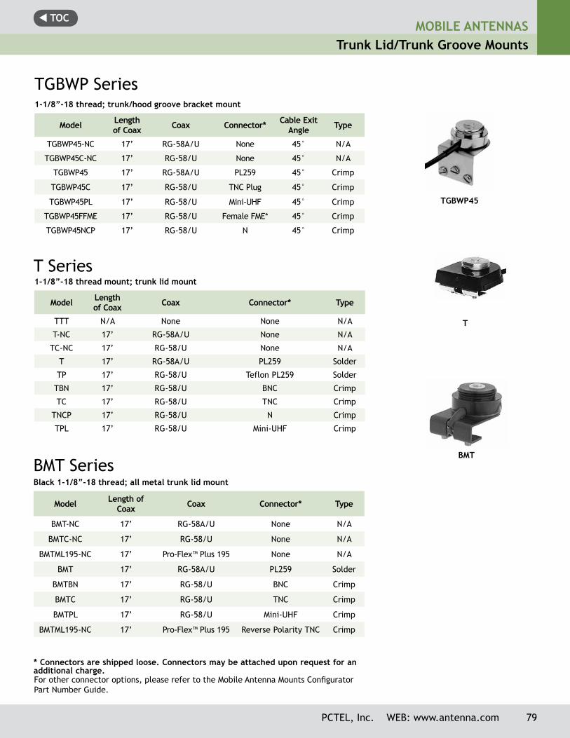
t TOCMOBILE ANTENNAS
Trunk Lid/Trunk Groove Mounts
PCTEL, Inc. WEB: www.antenna.com 79
1-1/8”-18 thread mount; trunk lid mount
Model Length of Coax Coax Connector* Type
TTT N/A None None N/A
T-NC 17’ RG-58A/U None N/A
TC-NC 17’ RG-58/U None N/A
T 17’ RG-58A/U PL259 Solder
TP 17’ RG-58/U Teflon PL259 Solder
TBN 17’ RG-58/U BNC Crimp
TC 17’ RG-58/U TNC Crimp
TNCP 17’ RG-58/U N Crimp
TPL 17’ RG-58/U Mini-UHF Crimp
T Series
BMT SeriesBlack 1-1/8”-18 thread; all metal trunk lid mount
Model Length of Coax Coax Connector* Type
BMT-NC 17’ RG-58A/U None N/A
BMTC-NC 17’ RG-58/U None N/A
BMTML195-NC 17’ Pro-Flex™ Plus 195 None N/A
BMT 17’ RG-58A/U PL259 Solder
BMTBN 17’ RG-58/U BNC Crimp
BMTC 17’ RG-58/U TNC Crimp
BMTPL 17’ RG-58/U Mini-UHF Crimp
BMTML195-NC 17’ Pro-Flex™ Plus 195 Reverse Polarity TNC Crimp
* Connectors are shipped loose. Connectors may be attached upon request for an additional charge.
T
BMT
1-1/8”-18 thread; trunk/hood groove bracket mount
Model Length of Coax Coax Connector* Cable Exit
Angle Type
TGBWP45-NC 17’ RG-58A/U None 45° N/A
TGBWP45C-NC 17’ RG-58/U None 45° N/A
TGBWP45 17’ RG-58A/U PL259 45° Crimp
TGBWP45C 17’ RG-58/U TNC Plug 45° Crimp
TGBWP45PL 17’ RG-58/U Mini-UHF 45° Crimp
TGBWP45FFME 17’ RG-58/U Female FME* 45° Crimp
TGBWP45NCP 17’ RG-58/U N 45° Crimp
TGBWP Series
TGBWP45
For other connector options, please refer to the Mobile Antenna Mounts Configurator Part Number Guide.
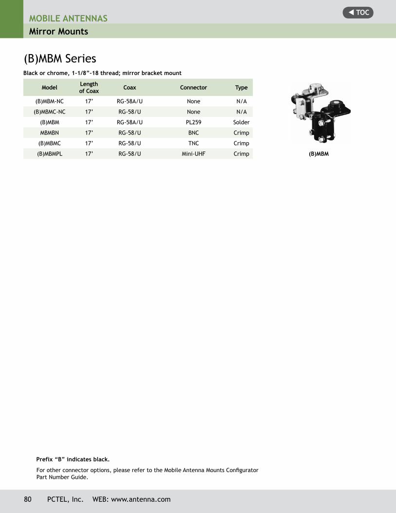
t TOCMOBILE ANTENNASMirror Mounts
80 PCTEL, Inc. WEB: www.antenna.com
(B)MBM SeriesBlack or chrome, 1-1/8”-18 thread; mirror bracket mount
Model Length of Coax Coax Connector Type
(B)MBM-NC 17’ RG-58A/U None N/A
(B)MBMC-NC 17’ RG-58/U None N/A
(B)MBM 17’ RG-58A/U PL259 Solder
MBMBN 17’ RG-58/U BNC Crimp
(B)MBMC 17’ RG-58/U TNC Crimp
(B)MBMPL 17’ RG-58/U Mini-UHF Crimp
Prefix “B” indicates black.
(B)MBM
For other connector options, please refer to the Mobile Antenna Mounts Configurator Part Number Guide.
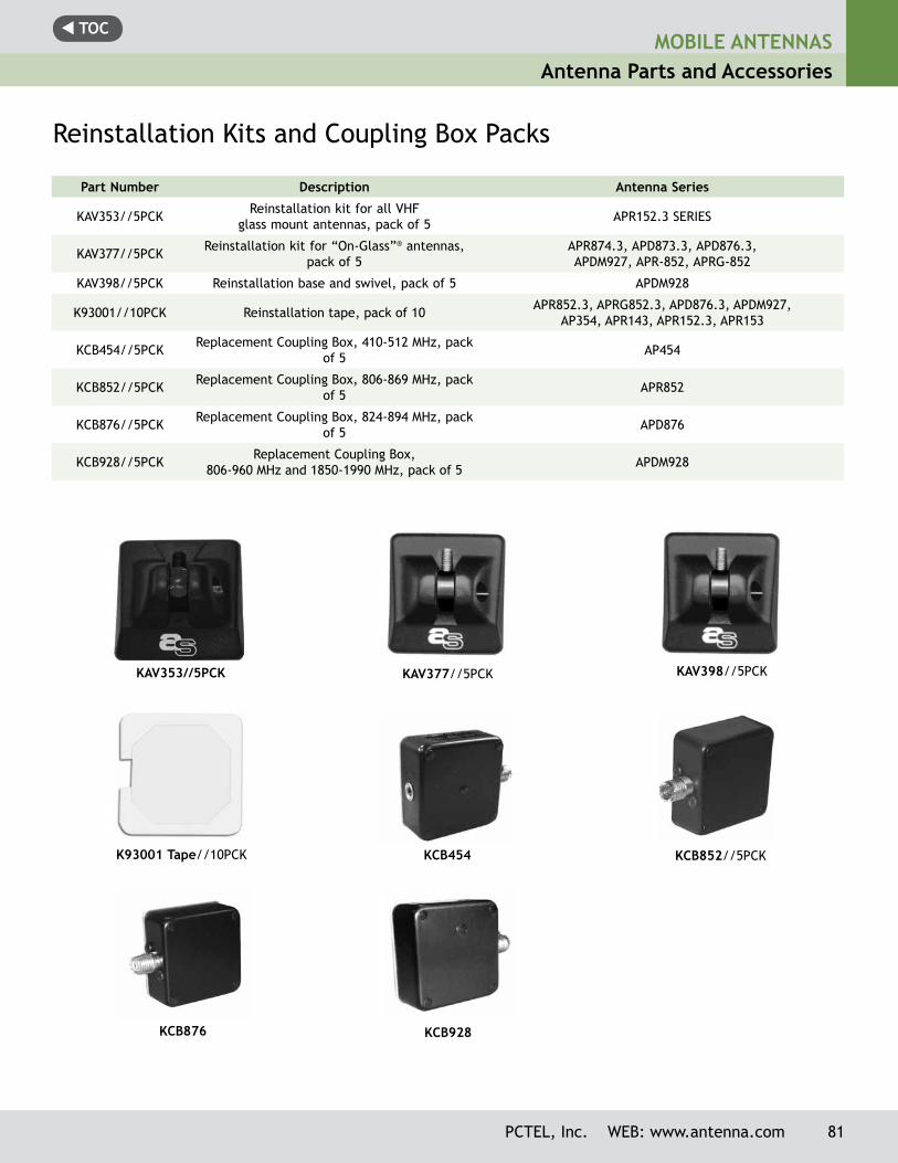
t TOCMOBILE ANTENNAS
Antenna Parts and Accessories
PCTEL, Inc. WEB: www.antenna.com 81
KAV377//5PCK KAV398//5PCK
KCB852//5PCKKCB454
Part Number Description Antenna Series
KAV353//5PCK Reinstallation kit for all VHF glass mount antennas, pack of 5 APR152.3 SERIES
KAV377//5PCK Reinstallation kit for “On-Glass”® antennas, pack of 5
APR874.3, APD873.3, APD876.3, APDM927, APR-852, APRG-852
KAV398//5PCK Reinstallation base and swivel, pack of 5 APDM928
K93001//10PCK Reinstallation tape, pack of 10 APR852.3, APRG852.3, APD876.3, APDM927, AP354, APR143, APR152.3, APR153
KCB454//5PCK Replacement Coupling Box, 410-512 MHz, pack of 5 AP454
KCB852//5PCK Replacement Coupling Box, 806-869 MHz, pack of 5 APR852
KCB876//5PCK Replacement Coupling Box, 824-894 MHz, pack of 5 APD876
KCB928//5PCK Replacement Coupling Box, 806-960 MHz and 1850-1990 MHz, pack of 5 APDM928
Reinstallation Kits and Coupling Box Packs
KCB928KCB876
K93001 Tape//10PCK
KAV353//5PCK
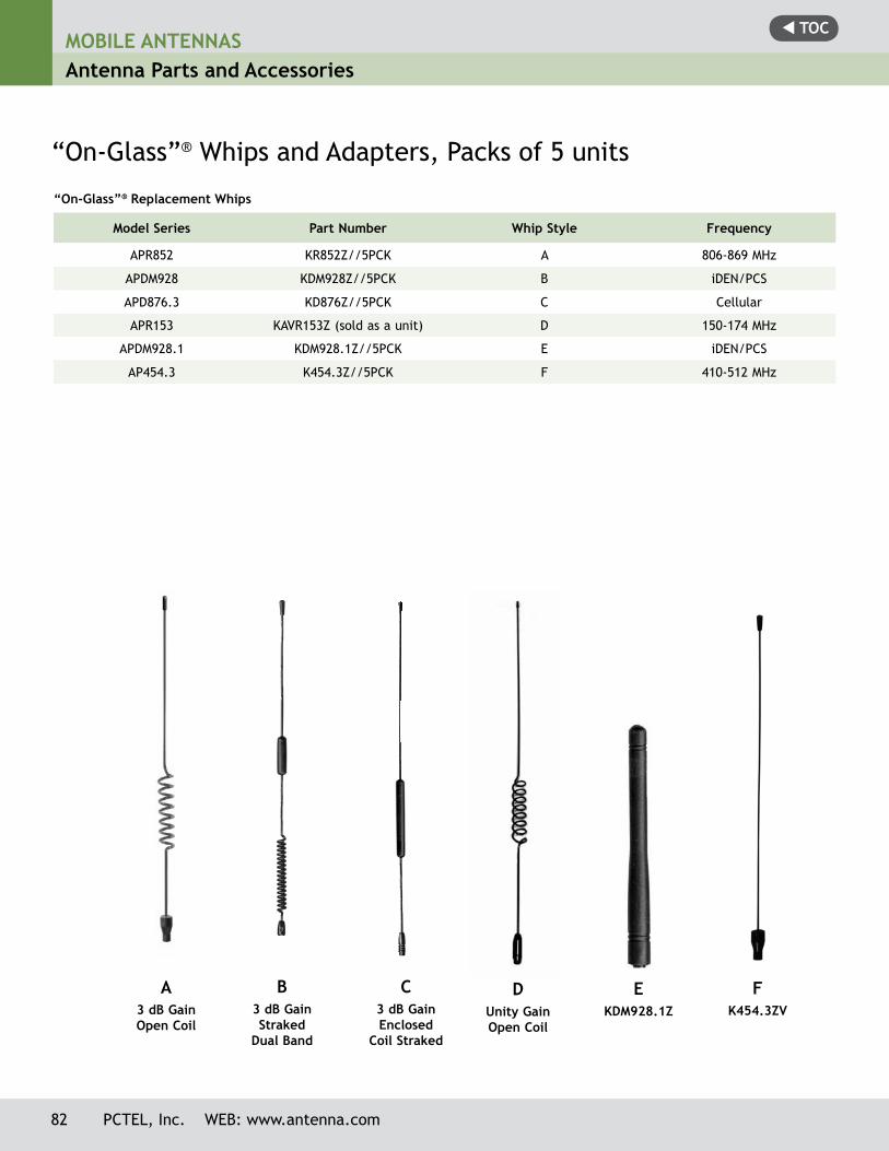
t TOCMOBILE ANTENNASAntenna Parts and Accessories
82 PCTEL, Inc. WEB: www.antenna.com
“On-Glass”® Replacement Whips
Model Series Part Number Whip Style Frequency
APR852 KR852Z//5PCK A 806-869 MHz
APDM928 KDM928Z//5PCK B iDEN/PCS
APD876.3 KD876Z//5PCK C Cellular
APR153 KAVR153Z (sold as a unit) D 150-174 MHz
APDM928.1 KDM928.1Z//5PCK E iDEN/PCS
AP454.3 K454.3Z//5PCK F 410-512 MHz
“On-Glass”® Whips and Adapters, Packs of 5 units
A3 dB Gain Open Coil
C3 dB Gain Enclosed
Coil Straked
B3 dB Gain Straked
Dual Band
DUnity GainOpen Coil
FK454.3ZV
EKDM928.1Z
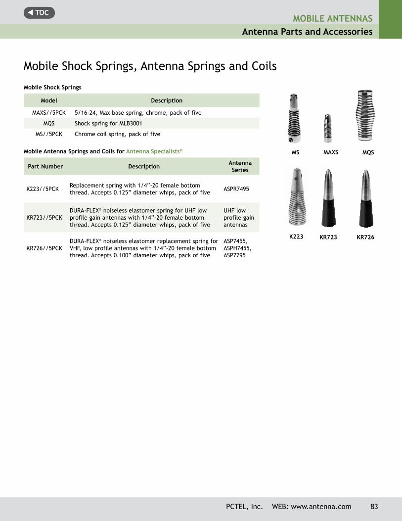
t TOCMOBILE ANTENNAS
Antenna Parts and Accessories
PCTEL, Inc. WEB: www.antenna.com 83
Mobile Shock Springs
Model Description
MAXS//5PCK 5/16-24, Max base spring, chrome, pack of five
MQS Shock spring for MLB3001
MS//5PCK Chrome coil spring, pack of five
Mobile Antenna Springs and Coils for Antenna Specialists®
Part Number Description Antenna Series
K223//5PCK Replacement spring with 1/4”-20 female bottom thread. Accepts 0.125” diameter whips, pack of five ASPR7495
KR723//5PCKDURA-FLEX® noiseless elastomer spring for UHF low profile gain antennas with 1/4”-20 female bottom thread. Accepts 0.125” diameter whips, pack of five
UHF low profile gain antennas
KR726//5PCKDURA-FLEX® noiseless elastomer replacement spring for VHF, low profile antennas with 1/4”-20 female bottom thread. Accepts 0.100” diameter whips, pack of five
ASP7455, ASPH7455, ASP7795
Mobile Shock Springs, Antenna Springs and Coils
MAXSMS
K223 KR723 KR726
MQS
t TOCMOBILE ANTENNASAntenna Parts and Accessories
84 PCTEL, Inc. WEB: www.antenna.com
Replacement Rods
ASP7455 ......................... KR731//5PCKASPB76552 ...................... KRB7242//5PCKASPC201 ......................... K42//5PCKMHB5800 ......................... MATH//5PCKMHB5800132 .................... MATH132//5PCKMHB5802 ......................... MATH//5PCKMHBDC5800 .................... MATH//5PCKMLB2700 ......................... MATH//5PCKMLB3000 ......................... MATH//5PCKMLB3001 ......................... MAR96MLB3400 ......................... MATH//5PCKMLB4000 ......................... MATH//5PCKMLB4700 ......................... MATH//5PCKMLB6600 ......................... MATH//5PCKMLBDC2700 ...................... MATH//5PCKMLBDC3000 ...................... MATH//5PCKMLBDC3400 ...................... MATH//5PCKMLBDC3700 ...................... MATH//5PCKMLBDC4000 ...................... MATH//5PCKMLBDC4500 ...................... MATH//5PCKMLBDC4700 ...................... MATH//5PCKMMC150 .......................... MATH//5PCKMUF4505 ......................... MUB450//5PCKMUF4505NGP .................... MUB450NGP//5PCKASP76551 ........................ KR724//5PCKASPRDM1994 .................... KRDM1994Z//5PCK
Antenna ReplacementModel .......................... Rod #
ASP7455 ......................... K725//5PCKASP76551 ........................ K722//5PCKMHB1520 ......................... MAT1520//5PCKMHB5800 ......................... MAT58//5PCKMHB5802 ......................... MAT582//5PCKMLB2700 ......................... MAT27//5PCKMLB3000 ......................... MAT30//5PCKMLB3001 ......................... MAT3001MLB3400 ......................... MAT34//5PCKMLB4000 ......................... MAT40//5PCKMLB4700 ......................... MAT47//5PCKMLB6600 ......................... MAT66//5PCKMUF4065 ......................... MAT406MUF4505 ......................... MAT450//5PCKMUF4505NGP .................... MAT450NGP//5PCKMWB1320 ........................ MATMWB//5PCKMWV1322 ........................ MATMWV//5PCKMWV1322HD..................... MATMWVHD//5PCK
Replacement Coils
Antenna ReplacementModel .......................... Coil #
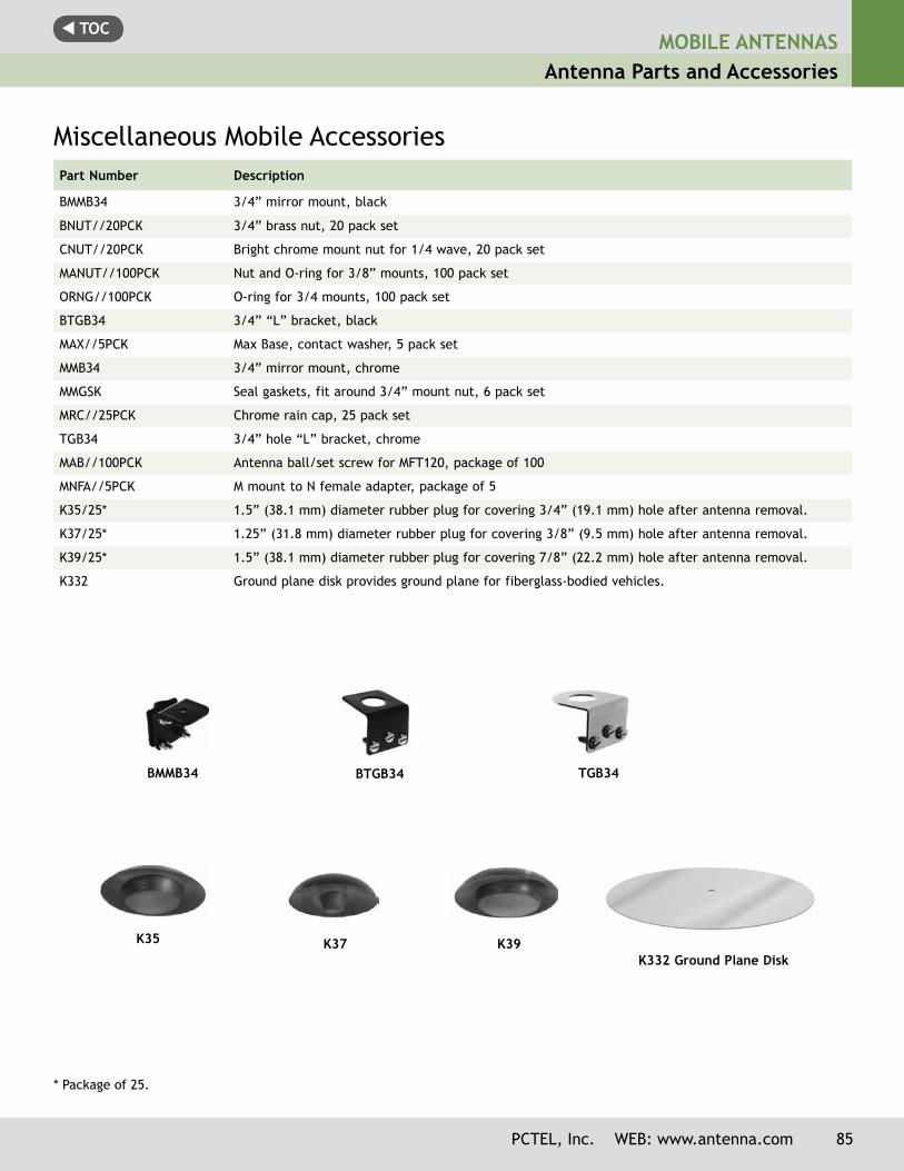
t TOCMOBILE ANTENNAS
Antenna Parts and Accessories
Miscellaneous Mobile AccessoriesPart Number Description
BMMB34 3/4” mirror mount, black
BNUT//20PCK 3/4” brass nut, 20 pack set
CNUT//20PCK Bright chrome mount nut for 1/4 wave, 20 pack set
MANUT//100PCK Nut and O-ring for 3/8” mounts, 100 pack set
ORNG//100PCK O-ring for 3/4 mounts, 100 pack set
BTGB34 3/4” “L” bracket, black
MAX//5PCK Max Base, contact washer, 5 pack set
MMB34 3/4” mirror mount, chrome
MMGSK Seal gaskets, fit around 3/4” mount nut, 6 pack set
MRC//25PCK Chrome rain cap, 25 pack set
TGB34 3/4” hole “L” bracket, chrome
MAB//100PCK Antenna ball/set screw for MFT120, package of 100
MNFA//5PCK M mount to N female adapter, package of 5
K35/25* 1.5” (38.1 mm) diameter rubber plug for covering 3/4” (19.1 mm) hole after antenna removal.
K37/25* 1.25” (31.8 mm) diameter rubber plug for covering 3/8” (9.5 mm) hole after antenna removal.
K39/25* 1.5” (38.1 mm) diameter rubber plug for covering 7/8” (22.2 mm) hole after antenna removal.
K332 Ground plane disk provides ground plane for fiberglass-bodied vehicles.
K35 K37 K39K332 Ground Plane Disk
* Package of 25.
BTGB34BMMB34 TGB34
PCTEL, Inc. WEB: www.antenna.com 85