Embed Size (px)
Citation preview
Mobile CommunicationsMobile CommunicationsSystems 1Systems 1
Rolando A CarrascoProfessor in Mobile CommunicationsBSc(Hons), PhD, CEng, [email protected] of Electrical, Electronic and Computing EngineeringUniversity of Newcastle upon tyne
2
Introduction (1)Introduction (1)
Mobile Computing Systems Types of wireless communication systems
– Cellular System Intra-cell/Inter-cell operation Frequency Re-use Channel Assignment Strategies Handoffs
– Interference and System Capacity Types of Interference Capacity/Interference Relation Improving Capacity in Cellular Systems
3
Introduction (2)Introduction (2)
Multiple Access in the Mobile Environment– Frequency Division Multiple Access (FDMA)– Time Division Multiple Access (TDMA)
Capacity and Interference for FDMA and TDMA Commercial Applications for FDMA & TDMA
– Spread Spectrum Multiple Access Techniques, Code Division Multiple Access (CDMA)
General Concepts and Characteristics Capacity and Interference in CDMA
– Other Multiple Access Techniques Universal Mobile Telecommunication Systems (UMTS)-ATM
Integration and Wireless ATM (WATM)– UMTS-ATM Integration– UMTS-ATM Network Architecture
4
Mobile Computing SystemsMobile Computing Systems
Rely on radio transmission as the final link between terminals– Finite resource, spectrum available is strictly limited– Multipath propagation, fading & interference– Terminals ability to move, complicates the system
The term mobile:– Any radio terminal, that can be moved during operation– Radio terminal that is attached to a high speed platform
(cellular telephone inside a vehicle) The term portable:
– A radio terminal that can be hand-held & used at walking speed
5
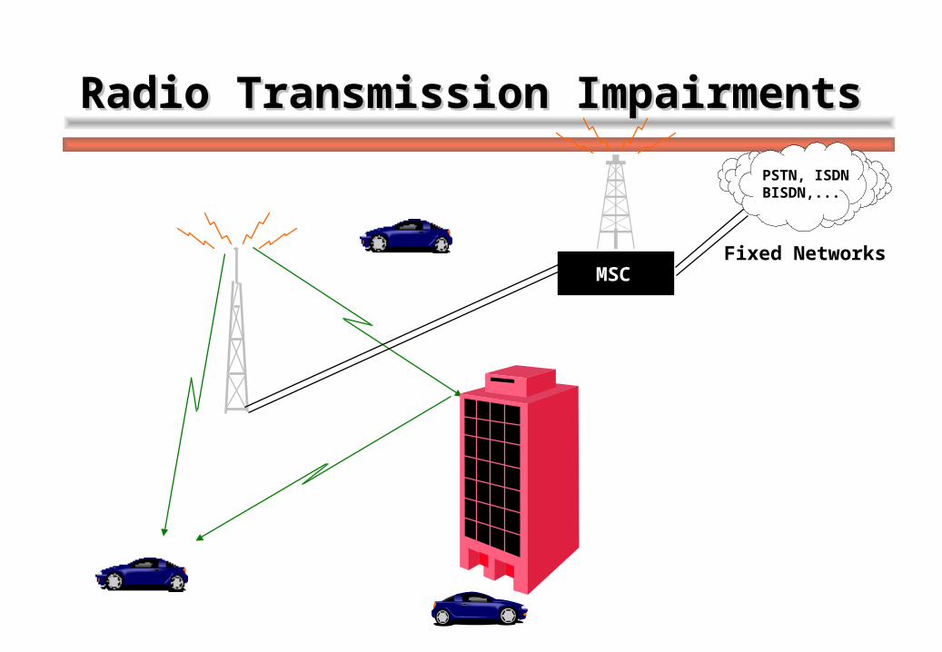
Radio Transmission ImpairmentsRadio Transmission Impairments
MSCFixed Networks
PSTN, ISDNBISDN,...
6
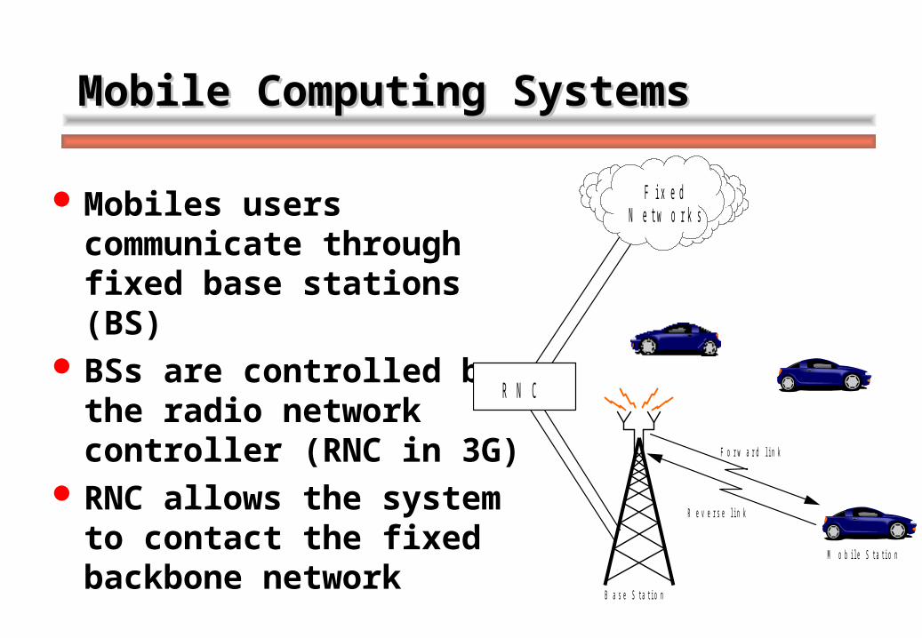
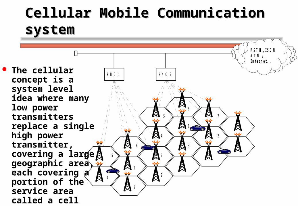
Mobile Computing SystemsMobile Computing Systems
Mobiles users communicate through fixed base stations (BS)
BSs are controlled by the radio network controller (RNC in 3G)
RNC allows the system to contact the fixed backbone network
F o r w a r d l i n k
R e v e r s e l i n k
B a s e S t a t i o n
M o b i l e S t a t i o n
R N C
F i x e d N e t w o r k s
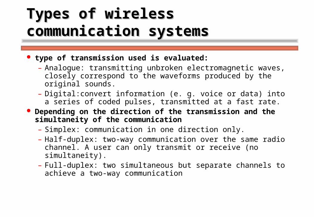
7Types of wireless communication Types of wireless communication systemssystems
type of transmission used is evaluated:– Analogue: transmitting unbroken electromagnetic waves, closely
correspond to the waveforms produced by the original sounds.– Digital:convert information (e. g. voice or data) into a series of
coded pulses, transmitted at a fast rate. Depending on the direction of the transmission and the
simultaneity of the communication– Simplex: communication in one direction only.– Half-duplex: two-way communication over the same radio
channel. A user can only transmit or receive (no simultaneity).– Full-duplex: two simultaneous but separate channels to achieve
a two-way communication
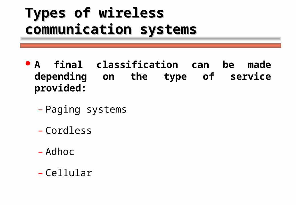
8Types of wireless communication Types of wireless communication systemssystems
A final classification can be made depending on the type of service provided:
– Paging systems
– Cordless
– Adhoc
– Cellular
9
Paging SystemsPaging Systems
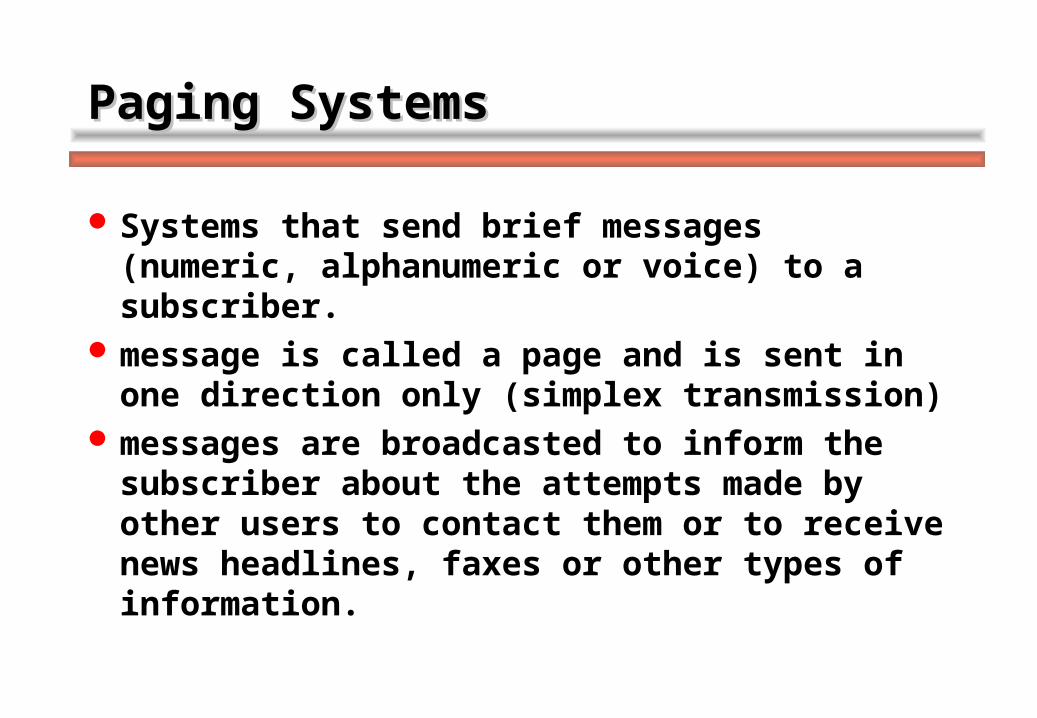
Systems that send brief messages (numeric, alphanumeric or voice) to a subscriber.
message is called a page and is sent in one direction only (simplex transmission)
messages are broadcasted to inform the subscriber about the attempts made by other users to contact them or to receive news headlines, faxes or other types of information.
10
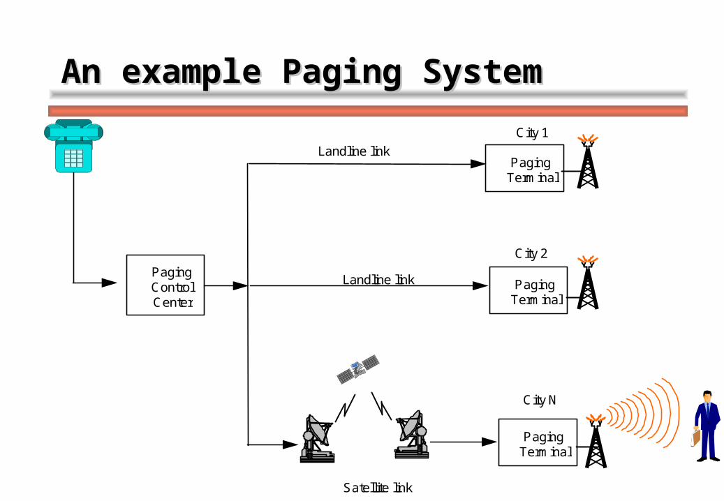
Paging Terminal
Paging Terminal
Paging Terminal
Paging Control Center
Landline link
Satellite link
Landline link
City 1
City 2
City N
An example Paging SystemAn example Paging System
11
CordlessCordless
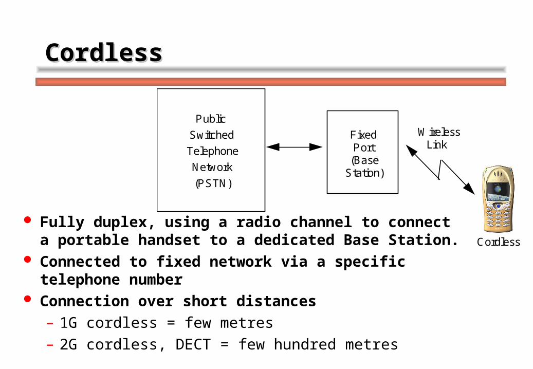
Fully duplex, using a radio channel to connect a portable handset to a dedicated Base Station.
Connected to fixed network via a specific telephone number
Connection over short distances– 1G cordless = few metres– 2G cordless, DECT = few hundred metres
Public Switched Telephone Network (PSTN)
Fixed Port
(Base Station)
Wireless Link
Cordless Handset
12
M o b i l e S t a t i o n
F i x e dN e t w o r k s
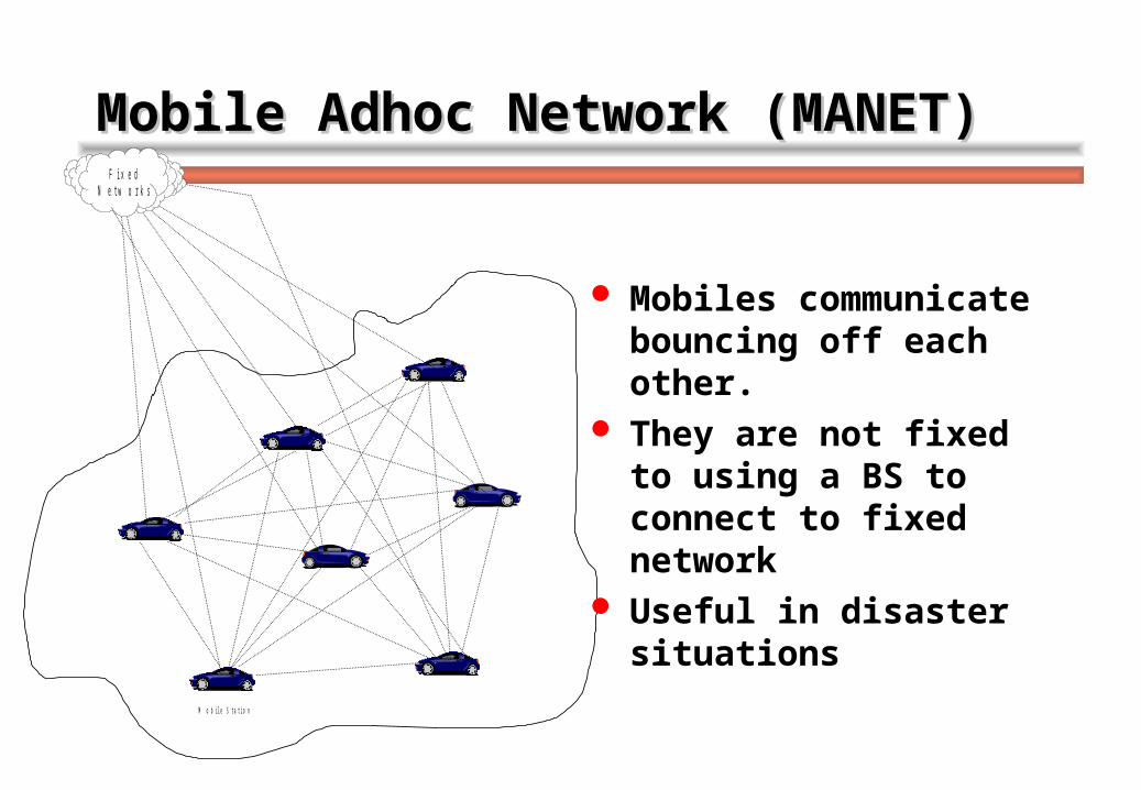
Mobile Adhoc Network (MANET)Mobile Adhoc Network (MANET)
Mobiles communicate bouncing off each other.
They are not fixed to using a BS to connect to fixed network
Useful in disaster situations
13
P S T N , I S D N A T M , I n t e r n e t . . .
R N C 2 R N C 1
1
1
2
2
3
3
4
4
5
5
6
6
7
7
Cellular Mobile Communication Cellular Mobile Communication systemsystem
The cellular concept is a system level idea where many low power transmitters replace a single high power transmitter, covering a large geographic area, each covering a portion of the service area called a cell
14
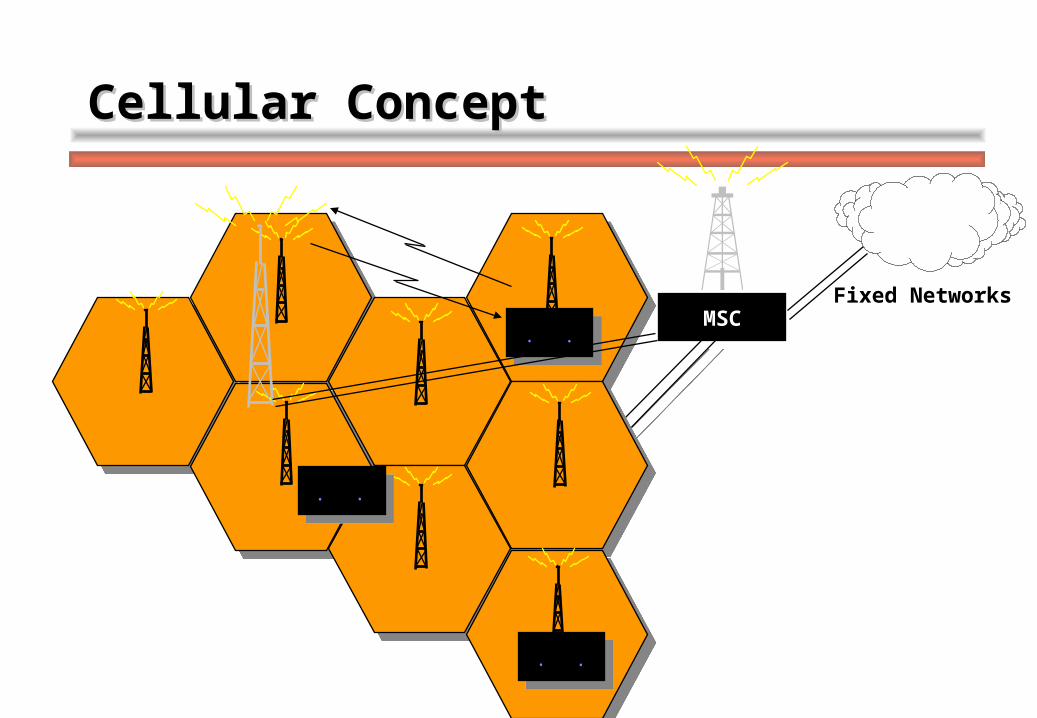
Cellular ConceptCellular Concept
MSCFixed Networks
PSTN, ISDNBISDN,...
15Cellular Mobile Communication Cellular Mobile Communication systemsystem
Mobile Units (MS)– mounted on vehicles or carried as portables– contain transceivers, antennas and control circuitry, – communicate with an assigned Base Station through
duplex radio channels Base stations (BS)
– several transmitters and receivers that through antennas communicate simultaneously with all mobiles within the area of coverage (cell) and are connected to radio network controller (RNC) via telephone lines or microwave links.
16Cellular Mobile Communication Cellular Mobile Communication systemsystem
– Each BS is allocated a portion of the total number of channels available to the entire system, which are used within a small geographic area (cell).
– Neighbouring BSs are assigned different groups of channels so that all the available channels are assigned to a relatively small number of Base Stations.
Radio Network Controller (RNC)– controls a number of cells– arranges Base Stations and channels for the mobiles – handles connections with the fixed Public Switched
Telephone Network (PSTN) and other fixed networks
17
Intra-cell/Inter-cell operationIntra-cell/Inter-cell operation
Base Station and mobiles communication is defined by a common air interface (CAI)
four different types of channels– two for voice or data transmission
The voice channel used to transmit from the Base Station to the Mobile Station is called the forward voice channel (FVC)
the channel used in the opposite direction is the reverse voice channel (RVC)
– two for control and signalling forward control channel (FCC) reverse control channel (RCC) in charge of the call set-up, channel quality measurements, handoff
procedure and other management functions.
18
Intra-cell/Inter-cell operationIntra-cell/Inter-cell operation
Each cell has allocated a number of channels– used for voice or signalling traffic– assigned according to a frequency re-use pattern– An active mobile registers with an appropriate BS– The mobile information and its cellular location are stored
in the RNC– When a call is set up either from or to the mobile
control & signalling system assigns a channel (from those available to the base station with which the mobile is registered) and instructs the mobile to use the corresponding channel. This is the channel assignment operation.
– A connection is established via the BS to the fixed network.
19
Intra-cell/Inter-cell operationIntra-cell/Inter-cell operation
The quality of the channel (radio link) is monitored by the BS for the duration of the call and reported to the RNC
RNC makes decisions concerning the quality and instructs the MS and BS accordingly.
When a mobile enters a different cell while a connection is in progress– the system, controlled by the RNC, assigns the mobile
to a new BS which has to provide new channels to the connection, if these are available.
This process is called a handoff.
20
Frequency Re-useFrequency Re-use
Each BS is allocated a different set of carrier frequencies
Each cell has a usable bandwidth associated with these carriers
No. of carrier frequencies available is limited It is therefore necessary to re-use the available
frequencies many times in order to provide sufficient channels for the required demand
This process is called frequency re-use All the cells with a different set of frequencies form a
cluster
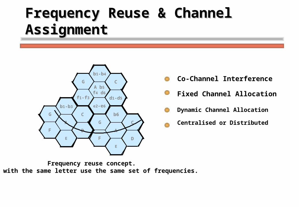
21Frequency Reuse & Channel Frequency Reuse & Channel AssignmentAssignment
Frequency reuse concept.Cells with the same letter use the same set of frequencies.
B
A
D
C
E
G
F
B
A
D
C
E
G
F
B
A
D
C
E
G
F
Co-Channel Interference
Fixed Channel Allocation
Dynamic Channel Allocation
Centralised or Distributed
A b5
f4 d6
b1-b4
d1-d5
C
e2-e6
G
f1-f3
A
b1-b3
D
C
E
G
F A
b6
D
C
E
G
F
22
Types of InterferenceTypes of Interference
Co-channel Interference -is independent of the transmitted power -is in function of the radius of the cell (R) -and the distance to the centre of the nearest
co-channel cell (D) Adjacent channel Interference Interference resulting from signals, which are
adjacent in frequency to the desired signal is called adjacent channel interference
23
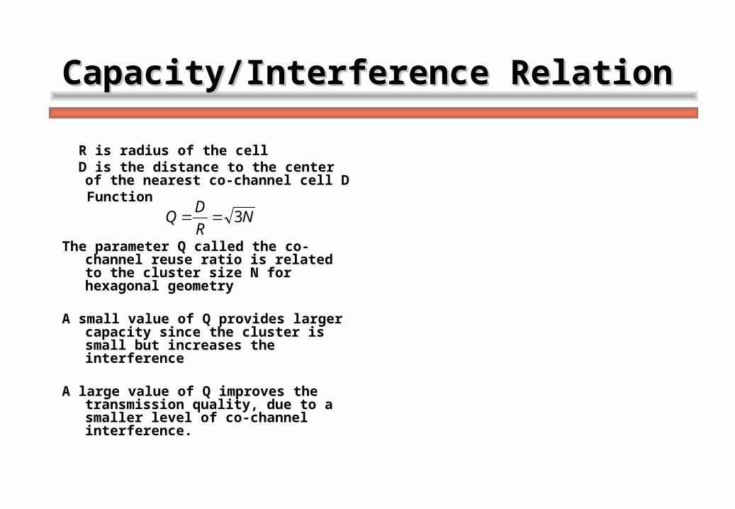
Capacity/Interference RelationCapacity/Interference Relation
R is radius of the cell D is the distance to the center of the
nearest co-channel cell D Function
The parameter Q called the co-channel reuse ratio is related to the cluster size N for hexagonal geometry
A small value of Q provides larger capacity since the cluster is small but increases the interference
A large value of Q improves the transmission quality, due to a smaller level of co-channel interference.
NR
DQ 3
24
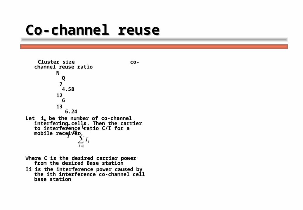
Co-channel reuse Co-channel reuse
Cluster size co-channel reuse ratio
N Q 7 4.58 12 6 13 6.24Let i0 be the number of co-channel
interfering cells. Then the carrier to interference ratio C/I for a mobile receiver
Where C is the desired carrier power
from the desired Base stationIi is the interference power caused by
the ith interference co-channel cell base station
0
1
i
iiI
C
I
C
25Propagation measurements in a Mobile Propagation measurements in a Mobile radio base stationradio base station
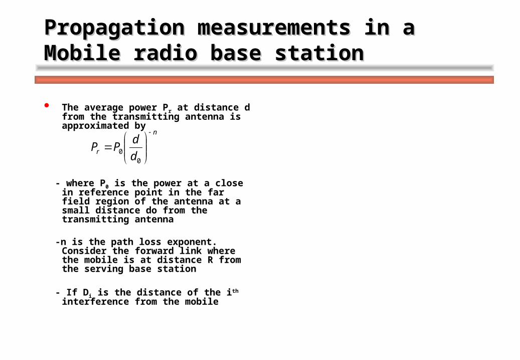
The average power Pr at distance d from the transmitting antenna is approximated by
- where P0 is the power at a close in reference point in the far field region of the antenna at a small distance do from the transmitting antenna
-n is the path loss exponent. Consider the forward link where the mobile is at distance R from the serving base station
- If Di is the distance of the ith interference from the mobile
n
r d
dPP
00
26
Carrier to interferenceCarrier to interference
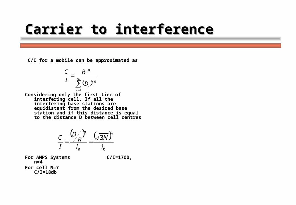
C/I for a mobile can be approximated as
Considering only the first tier of interfering cell. If all the interfering base stations are equidistant from the desired base station and if this distance is equal to the distance D between cell centres
For AMPS Systems C/I=17db, n=4For cell N=7 C/I=18db
0
1
i
i
ni
n
D
R
I
C
00
3
i
N
iR
D
I
Cnn
27
Carrier to Interfering Carrier to Interfering
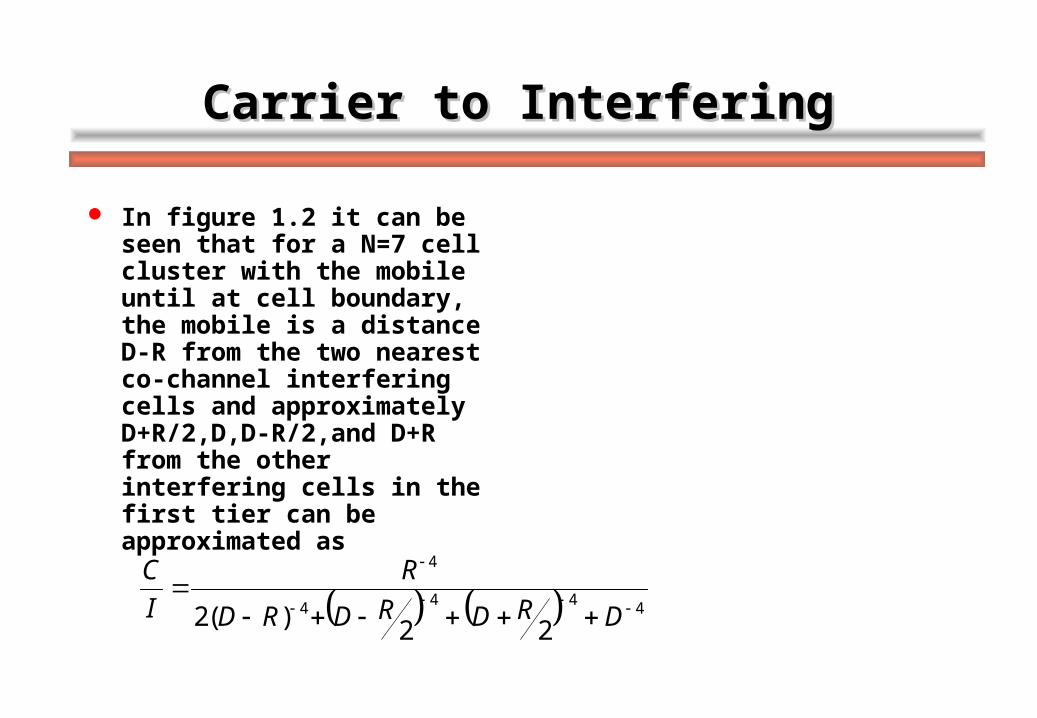
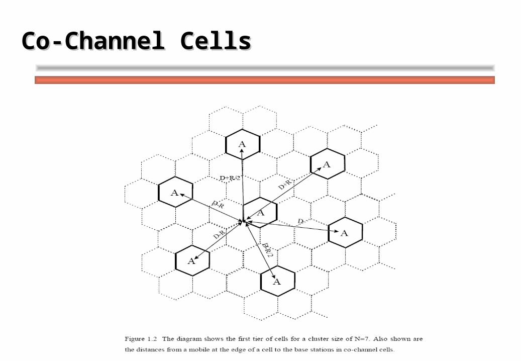
In figure 1.2 it can be seen that for a N=7 cell cluster with the mobile until at cell boundary, the mobile is a distance D-R from the two nearest co-channel interfering cells and approximately D+R/2,D,D-R/2,and D+R from the other interfering cells in the first tier can be approximated as
4444
4
22)(2
DRDRDRD
R
I
C
28
Co-Channel CellsCo-Channel Cells
29
Channel Assignment StrategiesChannel Assignment Strategies
The way the channels are assigned inside a cell affects the performance of the system– especially when a change of BSs occurs
Fixed Channel Allocation Schemes (FCA) Dynamic Channel Allocation (DCA) Hybrid Channel Allocation (HCA)
30
Fixed Channel Allocation (FCA)Fixed Channel Allocation (FCA)
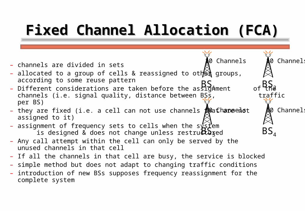
– channels are divided in sets– allocated to a group of cells & reassigned to other groups, according
to some reuse pattern– Different considerations are taken before the assignment of
the channels (i.e. signal quality, distance between BSs, traffic per BS)
– they are fixed (i.e. a cell can not use channels that are not assigned to it)
– assignment of frequency sets to cells when the system is designed & does not change unless restructured
– Any call attempt within the cell can only be served by the unused channels in that cell
– If all the channels in that cell are busy, the service is blocked– simple method but does not adapt to changing traffic conditions– introduction of new BSs supposes frequency reassignment for the complete system
BS1
BS3 BS4
BS2
10 Channels
10 Channels 10 Channels
10 Channels
31
Dynamic Channel Allocation (DCA)Dynamic Channel Allocation (DCA)
BS1
BS3 BS4
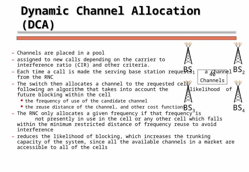
BS240Channels
– Channels are placed in a pool– assigned to new calls depending on the carrier to interference
ratio (CIR) and other criteria.– Each time a call is made the serving base station requests a channel from
the RNC– The switch then allocates a channel to the requested cell following an
algorithm that takes into account the likelihood of future blocking within the cell
the frequency of use of the candidate channel the reuse distance of the channel, and other cost functions.
– The RNC only allocates a given frequency if that frequency is not presently in use in the cell or any other cell which falls within the minimum restricted distance of frequency reuse to avoid interference
– reduces the likelihood of blocking, which increases the trunking capacity of the system, since all the available channels in a market are accessible to all of the cells
32
Dynamic Channel Allocation (DCA)Dynamic Channel Allocation (DCA)
Require the RNC to collect real-time data on – channel occupancy– traffic distribution– radio signal strength indications (RSSI) of all channels on a
continuous basis This increases the storage and computational load on the
system but provides the advantage of increased channel utilisation and decreased probability of a blocked call
Allocation of channels is more complex since additional information is needed, but is also more flexible to traffic changes (i.e. non-uniform traffic).
33
Hybrid Channel Allocation (HCA)Hybrid Channel Allocation (HCA)
a combination of both FCA and DCA some channels are pre-assigned others are shared dynamically One of these approaches is based on the principal of
borrowing channels from a neighbouring cell when its own channels are occupied
Known as the borrowing strategy RNC supervises such borrowing procedures &
ensures that the borrowing of a channel does not disrupt or interfere with any of the calls in progress in the donor cell
34
Allocation ComparisonAllocation Comparison
FCA better for high uniform traffic loads– Max reusability of channels is always achieved
DCA performs better for non-uniform traffic loads– allocation of channels is flexible
FCA schemes behave like a no. of small groups of servers DCA provides a way of making these small groups of
servers behave like a larger server, which is more efficient. FCA call must always be handed off into another channel
– same channel is not available in adjacent cells. DCA the same channel can be used if interference does not
occur.
35
Allocation ComparisonAllocation Comparison
variations in traffic that are typical of microcells are not well handled in FCA.
DCA techniques perform better in microcells Implementation complexity of DCA is higher than
FCA. – FCA:each cell has a number of channels and the
channel selection is made independently– DCA: the knowledge of occupied channels in other
cells is necessary (i.e. heavy signalling load).– A great deal of processing power to determine optimal
allocations is also required.
36
Allocation ControlAllocation Control
Centralised fashion– channels are assigned by a central controller, usually the
RNC Distributed fashion
– Channels are selected either by the local BS or by the mobile BS control: BSs keep info about current available channels in its
vicinity. – Updated by exchanging data between BSs. In a mobile control system
the mobile chooses the channel based in its local CIR measurements (i.e. lower complexity but less efficiency).
FCA is suitable for a centralised control system. DCA is applicable to a centralised or decentralised control
system