Embed Size (px)
Citation preview

M O B ILEE LE C TR O N IC S
T E C H N I C A L C A T A L O G
Electronic mobile POCLAIN HYDRAULICS
2 21/02/2014
Methodology :This document is intended for manufacturers of machines that incorporate Poclain Hydraulics products. It describes the technical characteristics of Poclain Hydraulics products and specifies installation conditions that will ensure optimum operation. This document includes important comments concerning safety. They are indicated in the following way:
This document also includes essential operating instructions for the product and general information. These are indicated in the following way:
The views in this document are created using metric standards. The dimensional data is given in mm and in inches (inches are between brackets and italic)
Associated documents
Safety comment.
Essential instructions.
General information .
Information on the model number.Information on the mo-del code.
Weight of component without oil.
Volume of oil.
Units.
Tightening torque.
Screws.
Information intended for Poclain-Hydraulics personnel.
Document typeGeneric installation 801478197L
The components of this booklet are not reparable.
Warranty reclaim of any disassembled components will not be accepted.
21/02/2014 3
CONTENTPOCLAIN HYDRAULICS Electronic mobile
Ele
ctr
on
ic c
on
tro
l u
nit
sE
lect
ron
ic c
om
po
nen
tsC
on
nec
tors
Cab
les
Dis
pla
ys
Electronic Control Units 5SmartDrive™ Easy ECU 5SmartDrive™ CT ECU 8SmartDrive™ Premier, Master, Offroad ECU 11
Displays 15Display 1.5 15Display 4.3C 17
Electronic components 19SmartDrive™ Test Unit 1912 V - 24 V Rotary actuator 20Speed sensor T4 23Speed sensor TR 25Speed sensor TD 27Magnetic incremental hollow shaft encoder 29Rotary potentiometer 3120 bar pressure sensor 3340 bar pressure sensor 35160 bar pressure sensor 37600 bar pressure sensor 39Digital sensors 41Analog temperature sensors 43Temperature switch 45Joystick with center lock 47Joystick with Z gate 49Electronic Travel pedal 51Travel / brake suspended pedal 55
Connectors 57SmartDrive™ Easy main connector 57SmartDrive Premier, Master, Offroad main connector 59SmartDrive™Communication connector 61SmartDrive™ Male communication connector 62SmartDrive™ CT main connector 64SmartDrive™ CT communication connector 66Connector kit 120ΩKit 68Display 4.3C main connector 703-pin Weather Pack connector 713-pin Metri Pack connector 726-pin Metri Pack connector 73EN 175301 - 803 style A Connector 74EN 175301 - 803 style A Connector with diode 752-pin AMP Timer Junior connector 774-pin Deutsch connector 78Connector actuator 79
Cables 80SmartDrive™ Easy cable 80SmartDrive™ Master cable 81SmartDrive™ Off-Road cable 82SmartDrive™ CT cable 83SmartDrive™ Easy adaptation cablefor SmartDrive test box 84SmartDrive™ communication cable 85Pressure sensors cable 864-pin M12 cable 875-pin M12 cable 885-pin M12 120 ohm cable 891 signal pedal connection cable 902 signal pedal connection cable 91

Electronic mobile POCLAIN HYDRAULICS
4 21/02/2014

21/02/2014 5
POCLAIN HYDRAULICS Electronic mobile
Ele
ctr
on
ic c
on
tro
l u
nit
sE
lect
ron
ic c
om
po
nen
tsC
on
nec
tors
Cab
les
Dis
pla
ys
SMARTDRIVE™ EASY ECU
Model code SD-EASY-PLUS SD-AUTOSD-EASY-
EXTENDEDSD-AUTO-
EXTENDED
Part number A30499B A22383E A42959U A42978Q
Features
Supply voltage 12 V DC24 V DC
Operating temperature- 40°C à 85°C
[-40°F à 185°F]Material Aluminum
Mass 0.5 kg[1.1 lb]
Mounting 4 x Ø 5.5 mm4 x [0.22" dia.]
ECU regulator protection index with its connectors IP 65(weather proofing)
Maximum current 14 AElectrical protection Excess voltage, reverse polarity, short circuitMicroprocessor 16 bitsMicroprocessor frequency 25 MHzFlash memory 128 Ko 256 KoECU programming Programming with a PC using the PHASES™ software applicationECU set-up Set-up with the software PHASES™ or the HHT
Electromagnetic compatibility
• IEC CISPR 25 : Measure of electromagnetic and radiated emissions.• ISO 11452 : Susceptibility to the radiations of electric fields.
• ISO 7637 : Immunity to transitory overvoltage.• ISO10605 : Immunity to electrostatic discharges.
Electronic Control Units
6 21/02/2014
Electronic mobile POCLAIN HYDRAULICS
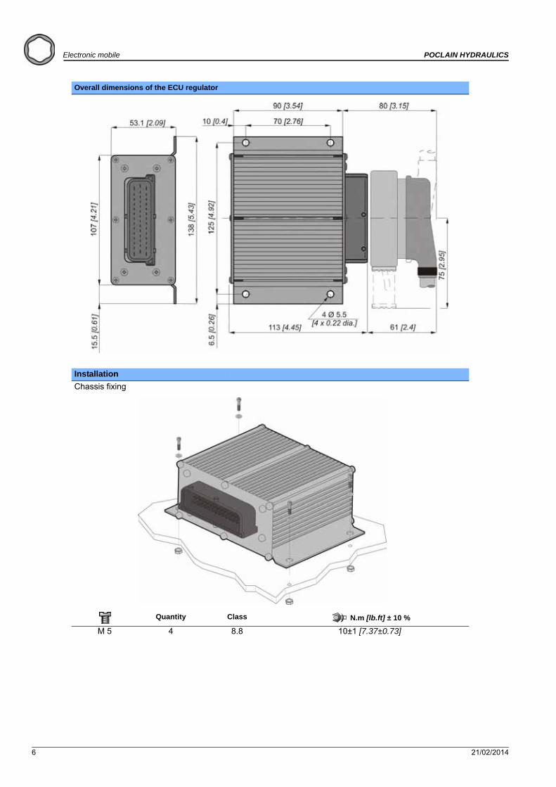
Overall dimensions of the ECU regulator
Installation
Chassis fixing
Quantity Class N.m [lb.ft] ± 10 %
M 5 4 8.8 10±1 [7.37±0.73]
21/02/2014 7
POCLAIN HYDRAULICS Electronic mobile
Ele
ctr
on
ic c
on
tro
l u
nit
sE
lect
ron
ic c
om
po
nen
tsC
on
nec
tors
Cab
les
Dis
pla
ys
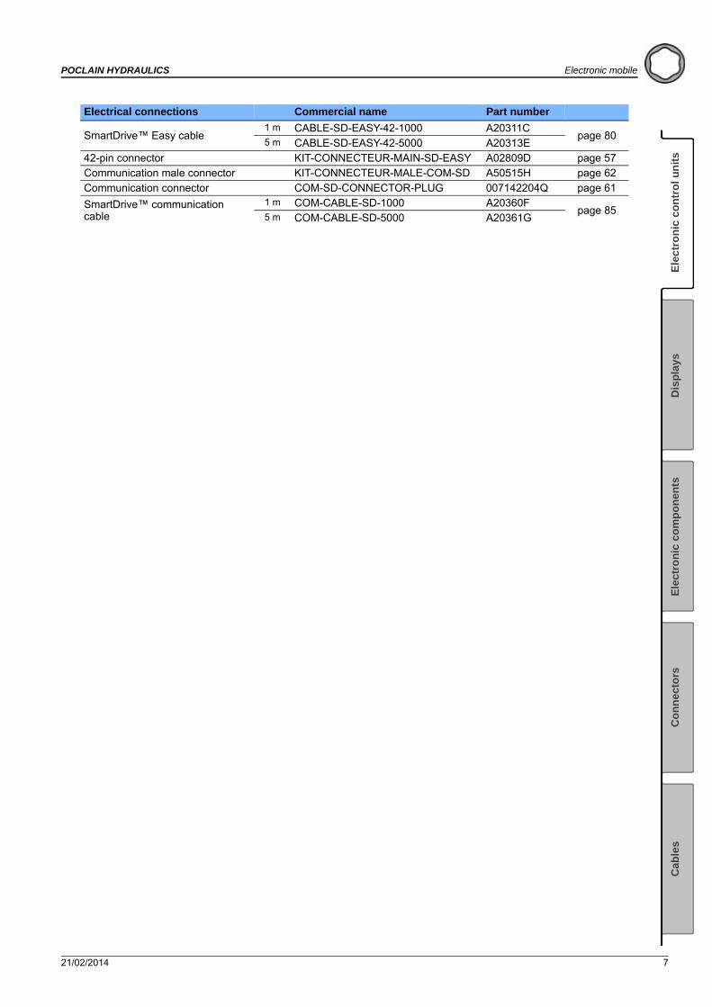
Electrical connections Commercial name Part number
SmartDrive™ Easy cable1 m CABLE-SD-EASY-42-1000 A20311C
page 805 m CABLE-SD-EASY-42-5000 A20313E
42-pin connector KIT-CONNECTEUR-MAIN-SD-EASY A02809D page 57Communication male connector KIT-CONNECTEUR-MALE-COM-SD A50515H page 62Communication connector COM-SD-CONNECTOR-PLUG 007142204Q page 61
SmartDrive™ communication cable
1 m COM-CABLE-SD-1000 A20360Fpage 85
5 m COM-CABLE-SD-5000 A20361G

8 21/02/2014
Electronic mobile POCLAIN HYDRAULICS
SMARTDRIVE™ CT ECU
Commercial name SD-CT-200 SD-CT-300
Part number A46841P A46842Q
Operating voltage 8 V to 32 V
Operating temperature - 40°C to 85°C [-40 °F to 185°F]
Overall dimensions See below
Material- Aluminum AISi9Cu3 (Box)
- PA66 plastic with 20% of fiberglass (cap)- Silicon (seal)
Mass1,270 kg ±10%[2,76 lb] ±10%
Mounting4 x Ø 7 mm
4 x [0.275" dia.]
Controller Ingress Protection with counterpart connectors mounted
IP 67 (according to EN60529 oct 1992)
Max. quiescent current consumption (ignition switched off) 5 mA
12V system max current 35,4 A
24V system max current 17 A
Maximum usageprofile:
12V System:(Supply voltage 16V)
- 6 HSD PWM outputs 400Hz, 95% 8 Ω loads
- 4 HSD digital outputs on, 6.15 Ω loads
- 8 HSD PWM outputs 400Hz, 95% 8 Ω loads
- 4 HSD digital outputs on, 6.15 Ω loads- 4 HSD digital outputs on, 8Ω loads
24V System:(Supply voltage 32V)
- 6 HSD PWM outputs 400Hz, 95% 32Ω loads- 4 HSD digital outputs on, 32Ω loads
- 8 HSD PWM outputs 400Hz, 95% 32Ω loads- 8 HSD digital outputs on, 32Ω loads
Performance level Capacity to reach PL d level according to ISO13849:2006 standard
Mean Time To Failure (MTTF)
85,1 years (ambient temperature of 40°C [104°F]) with operating profil of 11,87% (4 hours per day, 5 days per week, 52 weeks per year)
66,7 years (ambient temperature of 40°C [104°F]) with operating profil of 11,87% ( 4 hours per day, 5 days per week, 52 weeks per year)
Mean Time To Dangerous Failure (MTTFd) 224.2 years 173.1 years
Diagnostic Coverage (DC) 90,9% (medium) 90,7% (medium)
Category 2 2
Electrical protection Over-voltage, reverse polarity, ground and battery short circuit
Microcontroller One 32 bits microcontroller and one 8 bits microcontroller
ECU programming Programming with a PC using the PHASES™-CT software application
ECU set-up Set-up with the software PHASES™-CT
Universal inputs (UN) 9 15
Analog inputs (AN) 11 17
Frequency inputs (FIN) 5 8
Wake-Up Input (WUI) 1 1
Ground sense input (GND_SENSE) 1 1
HSD PWM 2A outputs 6 8
HSD DIG 2,6A outputs 4 4
HSD DIG 2A outputs 0 4
Low Side Digital output (LSD) 4A 0 3
Low Side Digital output (LSD) 5,2A 3 3
Sensor supply 5V 1 1
21/02/2014 9
POCLAIN HYDRAULICS Electronic mobile
Ele
ctr
on
ic c
on
tro
l u
nit
sE
lect
ron
ic c
om
po
nen
tsC
on
nec
tors
Cab
les
Dis
pla
ys
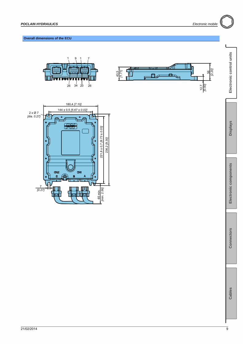
Overall dimensions of the ECU
1 9
26 34
1 7
20 26
2 x Ø 7[dia. 0.27]
43,5
[1.7
1]
12,7
[0.5
0]56
[2.2
0]
180,4 [7.10]22
1,8
± 0,
7 [8
.73
± 0.
03]
236,
2 [9
.30]
65 m
in.
[min
. 2.5
6]
144 ± 0,5 [5.67 ± 0.02]
7[0.27]
10 21/02/2014
Electronic mobile POCLAIN HYDRAULICS
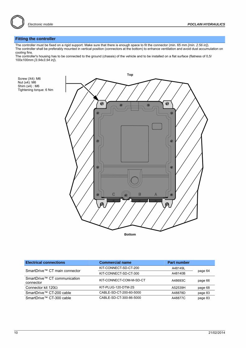
Fitting the controller
The controller must be fixed on a rigid support. Make sure that there is enough space to fit the connector (min. 65 mm [min. 2.56 in]).The controller shall be preferably mounted in vertical position (connectors at the bottom) to enhance ventilation and avoid dust accumulation on cooling fins.The controller's housing has to be connected to the ground (chassis) of the vehicle and to be installed on a flat surface (flatness of 0,5/100x100mm [3.94x3.94 in]).
Electrical connections Commercial name Part number
SmartDrive™ CT main connectorKIT-CONNECT-SD-CT-200 A48149L
page 64KIT-CONNECT-SD-CT-300 A48140B
SmartDrive™ CT communication connector
KIT-CONNECT-COM-M-SD-CT A48693C page 66
Connector kit 120 KIT-PLUG-120-DTM-2S A52539H page 68
SmartDrive™ CT-200 cable CABLE-SD-CT-200-60-5000 A48878D page 83
SmartDrive™ CT-300 cable CABLE-SD-CT-300-86-5000 A48877C page 83
Screw (X4): M6Nut (x4): M6Shim (x4) : M6Tightening torque: 6 Nm
Top
Bottom
21/02/2014 11
POCLAIN HYDRAULICS Electronic mobile
Ele
ctr
on
ic c
on
tro
l u
nit
sE
lect
ron
ic c
om
po
nen
tsC
on
nec
tors
Cab
les
Dis
pla
ys
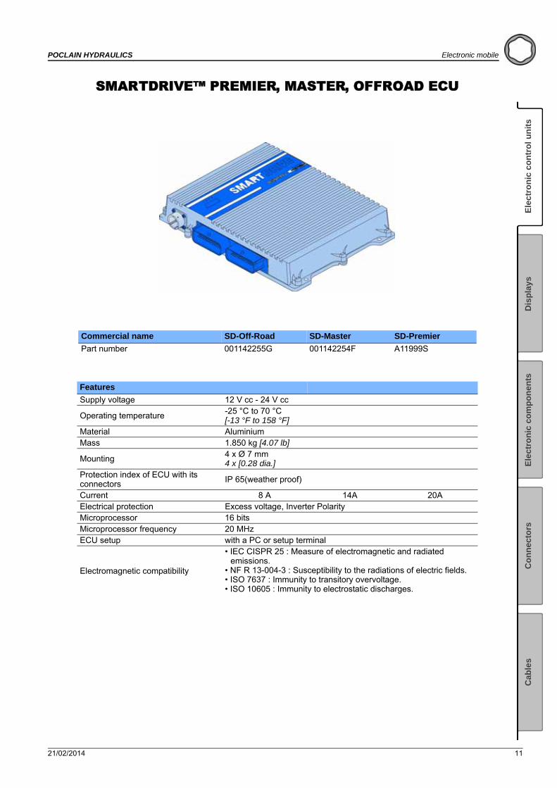
SMARTDRIVE™ PREMIER, MASTER, OFFROAD ECU
Commercial name SD-Off-Road SD-Master SD-Premier
Part number 001142255G 001142254F A11999S
Features
Supply voltage 12 V cc - 24 V cc
Operating temperature -25 °C to 70 °C[-13 °F to 158 °F]
Material AluminiumMass 1.850 kg [4.07 lb]
Mounting 4 x Ø 7 mm 4 x [0.28 dia.]
Protection index of ECU with its connectors IP 65(weather proof)
Current 8 A 14A 20AElectrical protection Excess voltage, Inverter PolarityMicroprocessor 16 bitsMicroprocessor frequency 20 MHzECU setup with a PC or setup terminal
Electromagnetic compatibility
• IEC CISPR 25 : Measure of electromagnetic and radiated emissions.
• NF R 13-004-3 : Susceptibility to the radiations of electric fields.• ISO 7637 : Immunity to transitory overvoltage.• ISO 10605 : Immunity to electrostatic discharges.
12 21/02/2014
Electronic mobile POCLAIN HYDRAULICS
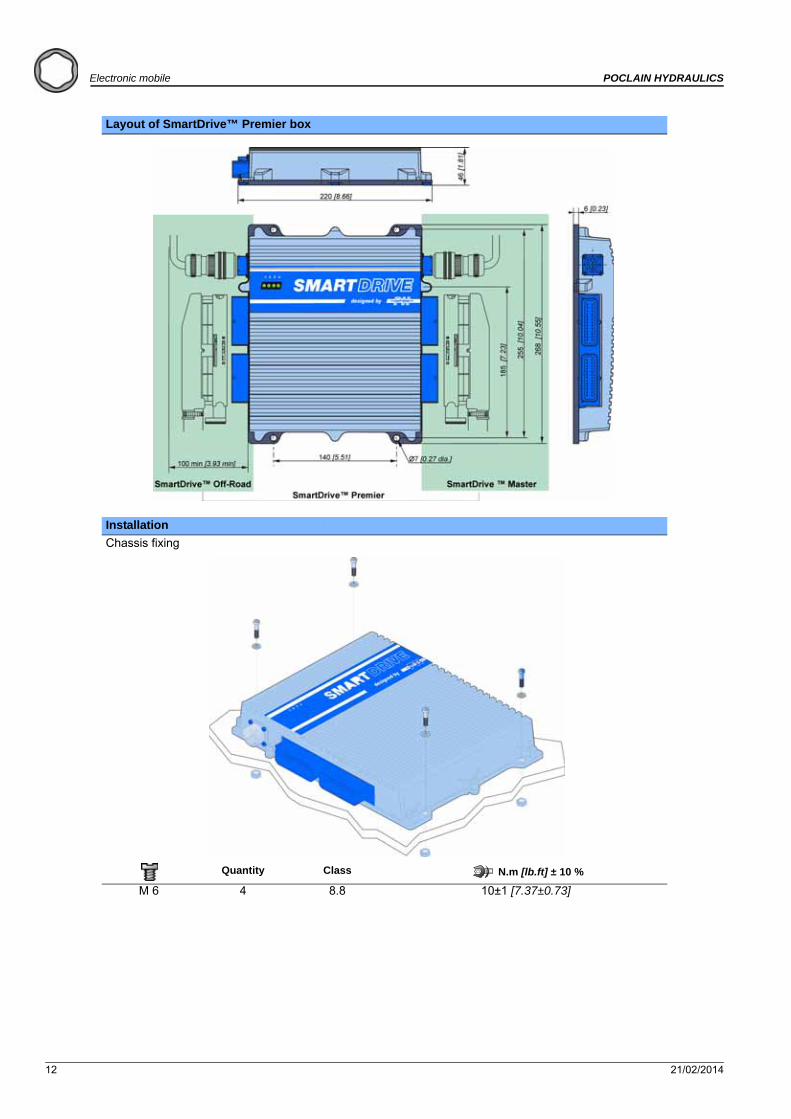
Layout of SmartDrive™ Premier box
Installation
Chassis fixing
Quantity Class N.m [lb.ft] ± 10 %
M 6 4 8.8 10±1 [7.37±0.73]

21/02/2014 13
POCLAIN HYDRAULICS Electronic mobile
Ele
ctr
on
ic c
on
tro
l u
nit
sE
lect
ron
ic c
om
po
nen
tsC
on
nec
tors
Cab
les
Dis
pla
ys
Electrical connections Commercial name Part number
56-pin main connector KIT-CONNECTOR-MAIN-SD 007142203P page 59Communication connector COM-SD-CONNECTOR-PLUG 007142204Q page 61
SmartDrive™ Master cable1 m CABLE-SD-MASTER-56-1000 A20309A
page 815 m CABLE-SD-MASTER-56-5000 A20310B
SmartDrive™ Off-Road cable1 m CABLE-SD-OFFROAD-56-1000 A22473C
page 825 m CABLE-SD-OFFROAD-56-5000 A22475E
SmartDrive™ communication cable
1 m COM-CABLE-SD-1000 A20360Fpage 85
5 m COM-CABLE-SD-5000 A20361G
When wiring, check that the wire can neither be cut off, nor torn off when the machine is working or moving.

14 21/02/2014
Electronic mobile POCLAIN HYDRAULICS

21/02/2014 15
POCLAIN HYDRAULICS Electronic mobile
Ele
ctr
on
ic c
on
tro
l u
nit
sE
lect
ron
ic c
om
po
nen
tsC
on
nec
tors
Cab
les
Dis
pla
ys
DISPLAY 1.5
SD Display 1.5
Function Displays informations (engine or pump RPM, pressure, error codes and their designations...)
Part number A47449A
Features
Electrical data
DC power supply 9 to 60 VCurrent consumption at 24 V <100 mAProgram flash memory 96 kBEEPROM memory 64 kBSRAM memory 3.3 kBScreen BacklightedDisplay type LCD, 2 x 8 charactersKeys 3 (illuminated)Light indicators 3
Mechanical data
Operating temperature - 20 °C to + 70 °C [-4 °F to 158 °F]Weight 63 gMounting Mounting hole 53 mmDegree of protection IP 65 on the front; IP54 on the back
Interfaces/ProtocolsCAN 1 (ISO 11898, 2.0B)Layer 2, CANopen, J1939
Accessory Commercial name Part number
5 pin M12 cable CABLE-M12-180°-2000-5PT A19974L page 885 pin M12 120 Ohm cable CABLE-COM-M12-CAN-120 A25657N page 89
Layout
52 [d
ia. 2
.05]
60
[dia
. 2.3
6]
57,9
[2.2
8]
1
2
3
4
5
10 [0.39]40,9 [1.61]
5-pin M12 connector
1: Ground2: VDC3: CAN GND (internally connected to ground)4: CAN H5: CAN L
Top
Bottom
5-pin M12 connector
View A
View A
Displays

16 21/02/2014
Electronic mobile POCLAIN HYDRAULICS
Description
Functioning
Display the Informations and the Parameters
Press the key -------and--------to navigate into the Informations and the Parameters.
When the tuning light signal is off-------the SD Display 1.5 displays an Information (the value can not be changed).
When the tuning light signal is on-------the SD Display 1.5 displays a Parameters (the value can be changed).
Tune the Parameters values
Only the Parameters values can be tuned (the tuning light indicator is on-------).
1 - Press the key-------to enter into the tuning mode.
The tuning light indicator flashes---------.
2 - Press the key--------to increase the value , or the key--------to decrease the value .
3 - Press the key-------to exit from the tuning mode.
The tuning light indicator stops flashing--------(but it still on).
Display the Error(s)
The flashing error light indicator-------indicates the presence of error(s).
1 - Press the key--------to display the errors(s) and--------to come back into the previous error(s).
2 - Press the key--------to display the Informations and the Parameters.
The error light indicator is off-------when the error(s) is(are) corrected.
N° Function
Error light indicator
Tuning light indicator
’’Information’’, ’’Parameter’’ or ’’Error code’’ line
’’Value’’ or ’’Error identification’’ line
’’Previous’’ or ’’Decrease of the value’’ key
’’Enter’’ or ’’Exit’’ key
’’Next’’ or ’’Increase of the value’’ key
Can not be changed Can not be changed Can be changed Can be changed
21/02/2014 17
POCLAIN HYDRAULICS Electronic mobile
Ele
ctr
on
ic c
on
tro
l u
nit
sE
lect
ron
ic c
om
po
nen
tsC
on
nec
tors
Cab
les
Dis
pla
ys
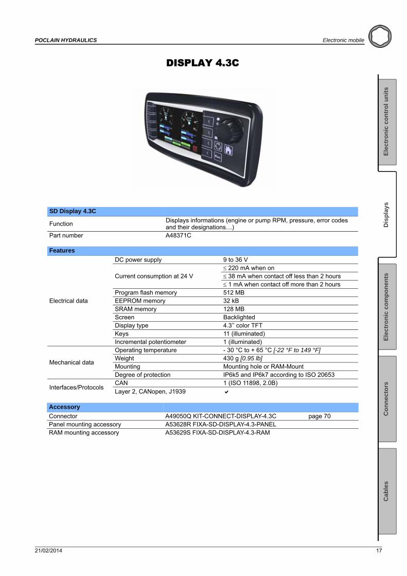
DISPLAY 4.3C
SD Display 4.3C
FunctionDisplays informations (engine or pump RPM, pressure, error codes and their designations…)
Part number A48371C
Features
Electrical data
DC power supply 9 to 36 V
Current consumption at 24 V 220 mA when on 38 mA when contact off less than 2 hours 1 mA when contact off more than 2 hours
Program flash memory 512 MBEEPROM memory 32 kBSRAM memory 128 MBScreen BacklightedDisplay type 4.3’’ color TFT Keys 11 (illuminated)Incremental potentiometer 1 (illuminated)
Mechanical data
Operating temperature - 30 °C to + 65 °C [-22 °F to 149 °F]Weight 430 g [0.95 lb]Mounting Mounting hole or RAM-MountDegree of protection IP6k5 and IP6k7 according to ISO 20653
Interfaces/ProtocolsCAN 1 (ISO 11898, 2.0B)Layer 2, CANopen, J1939
Accessory
Connector A49050Q KIT-CONNECT-DISPLAY-4.3C page 70Panel mounting accessory A53628R FIXA-SD-DISPLAY-4.3-PANELRAM mounting accessory A53629S FIXA-SD-DISPLAY-4.3-RAM
18 21/02/2014
Electronic mobile POCLAIN HYDRAULICS
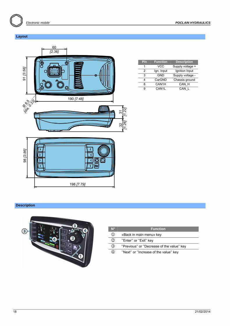
Layout
Description
198 [7.79]
98 [3
.86]
31[1
.22]
32[1
.26]
190 [7.48]
91 [3
.58]
60[2.36]
Ø 8,5
[dia.
0.33]
Pin Function Description
1 VCC Supply voltage +
2 Ign. Input Ignition Input
3 GND Supply voltage -
4 CarGND Chassis ground
8 CAN1H CAN_H
9 CAN1L CAN_L
1
3
4 2
34 N° Function
«Back in main menu» key
’’Enter’’ or ’’Exit’’ key
’’Previous’’ or ’’Decrease of the value’’ key
’’Next’’ or ’’Increase of the value’’ key

21/02/2014 19
POCLAIN HYDRAULICS Electronic mobile
Ele
ctr
on
ic c
on
tro
l u
nit
sE
lect
ron
ic c
om
po
nen
tsC
on
nec
tors
Cab
les
Dis
pla
ys
SMARTDRIVE™ TEST UNIT
Commercial name TEST-BOX-SD
Part number 005142203B
Function Check the wiring by isolating each wire between the machine and the electronic unit (workshop use).
Compatibility Transmissions controlled by a unit in the SmartDrive™ range
Features
Size of unit 250 x 250 x 100 (L x l x h)
Components 112 safety bases (4 mm banana sockets)
56 shunt jumpers (4 mm double banana plug)
2 packing glands
1 cable, 2 m long, with sheet-protected female connector / connected to Black banana sockets (unit side)
1 cable, 2 m long, with metal protected male connector / connected to Red banana sockets (machine side)
Maximum voltage 60 V DC
Operating temperature - 40 °C to + 80 °C [- 40 °F to 176 °F]
Electrical connections Commercial name Part number
Fitting SmartDrive™ Easy cable for SmartDrive™ test box CABLE-EASY-SD-TEST-BOX A05786P page 84
Fitting test box SmartDrive™ cable for SmartDrive™ Easy CABLE-SD-EASY-TEST-BOX A05785N page 84
Electronic components

20 21/02/2014
Electronic mobile POCLAIN HYDRAULICS
12 V - 24 V ROTARY ACTUATOR
Commercial name ACTIONNEUR E GAS II 12 V
Part number 005743902W
Commercial name ACTIONNEUR E GAS II 24 V
Part number 005743901V
Function Controls injection on heat engines that are not controlled by a CAN bus.
Compatibility Electronic transmission management
Features
Voltage 12/24 Vcc
Motor torque 1.80 Nm [1.33 lb.ft]
Mechanical travel 120°
Electrical travel 90° ± 3.7°
Operating temperature - 40 °C to + 120 °C [- 40 °F to 248 °F]
Protection class IP56

21/02/2014 21
POCLAIN HYDRAULICS Electronic mobile
Ele
ctr
on
ic c
on
tro
l u
nit
sE
lect
ron
ic c
om
po
nen
tsC
on
nec
tors
Cab
les
Dis
pla
ys
Layout
Installation
Chassis fixing The actuator must be secured on a plate at least 4 mm [0.16"] thick.
Ref. Thread depth Quantity Class N.m [lb.ft]
M 6 12 mm [0.47] 3 8.8 8 ± 0.4 [5.9 ± 0.29]
Idle speed range
Zero of electrical travel
1
22 21/02/2014
Electronic mobile POCLAIN HYDRAULICS
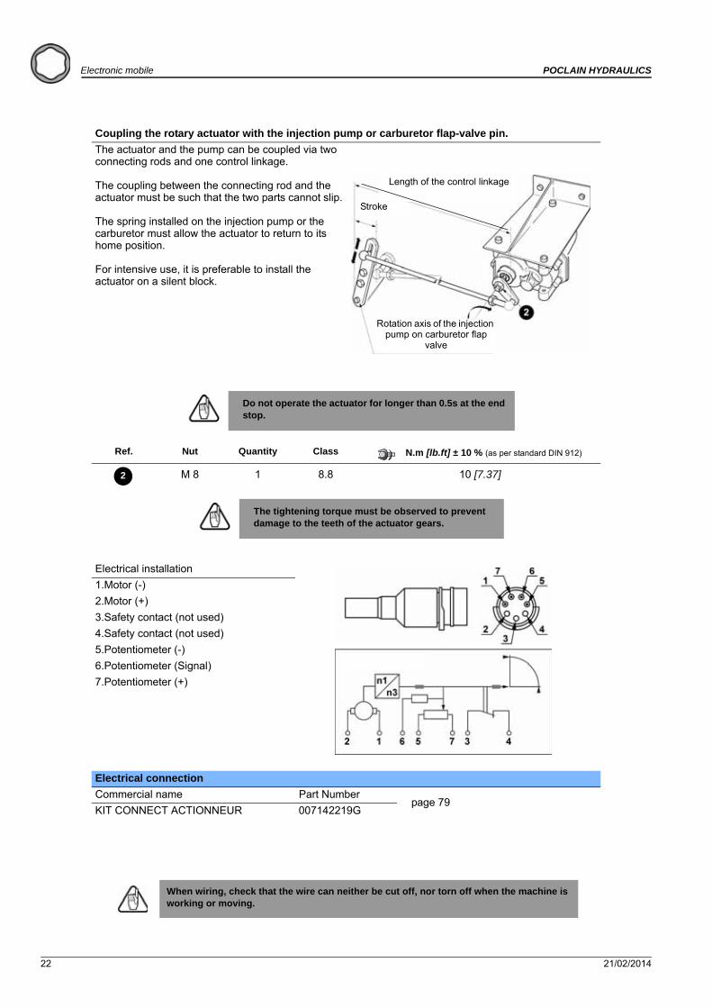
Coupling the rotary actuator with the injection pump or carburetor flap-valve pin.
The actuator and the pump can be coupled via two connecting rods and one control linkage.
The coupling between the connecting rod and the actuator must be such that the two parts cannot slip.
The spring installed on the injection pump or the carburetor must allow the actuator to return to its home position.
For intensive use, it is preferable to install the actuator on a silent block.
Do not operate the actuator for longer than 0.5s at the end stop.
Ref. Nut Quantity Class N.m [lb.ft] ± 10 % (as per standard DIN 912)
M 8 1 8.8 10 [7.37]
The tightening torque must be observed to prevent damage to the teeth of the actuator gears.
Electrical installation
1.Motor (-)
2.Motor (+)
3.Safety contact (not used)
4.Safety contact (not used)
5.Potentiometer (-)
6.Potentiometer (Signal)
7.Potentiometer (+)
Electrical connection
Commercial name Part Numberpage 79
KIT CONNECT ACTIONNEUR 007142219G
When wiring, check that the wire can neither be cut off, nor torn off when the machine is working or moving.
Length of the control linkage
Stroke
Rotation axis of the injection pump on carburetor flap
valve
2

21/02/2014 23
POCLAIN HYDRAULICS Electronic mobile
Ele
ctr
on
ic c
on
tro
l u
nit
sE
lect
ron
ic c
om
po
nen
tsC
on
nec
tors
Cab
les
Dis
pla
ys
SPEED SENSOR T4
Commercial name T4 SENSOR 12-44 T4 SENSOR 12-53 T4 SENSOR 12-62
Part number A22082C A22083D A22084E
Lenght L(*) 44 [1.73] 53 [2.09] 62 [2.44]
Function Detect movements : rotation speed
Compatibility Electronic transmission management
(*) : According to the size of the motor, consult your Poclain Hydraulics sales engineer
Features
Supply voltage 8 - 30 V
Output type - 1 push-pull square frequency signal- Maximum load current: 20 mA- Voltage at low state: < 1.5 V- Voltage at high state: > (power supply voltage - 3.5 V)
Maximum range 1.15 mm [0.045’’]
Current consumption 20 mA max.
Frequency range 0 to 15 kHz
Operating temperature - 40°C to + 125°C [- 40°F to 257°F]
Material Stainless steel
Protection rating IP68 (sensitive side) / IP67 (connector side)
Electrical protection Reverse polarity
Signals are not protected against short circuit to ground or supply.
No detection of the rotation direction.

24 21/02/2014
Electronic mobile POCLAIN HYDRAULICS
Layout
Installation
Disconnecting the accessories and speed set up
In the case of motors predisposed to speed, the existing shutter needs to be removed and eliminated before installing the sensor and its attachment device.
To install the sensor, see the ''Installation guide'' brochure No. 801478197L.
Connection of the speed sensor
Remove the plastic plug on the connector.
Function Pin number
Power supply 1
Not present 2
Ground 3
Square frequency signal 4
For the connection of connectors, please refer to the connection table and the general cabling plan contained in the installation brochure for your transmission.
Electrical connections 90° 180°
Commercial name ELEC-CABLE-M12-90°-5000 ELEC-CABLE-M12-180°-5000
Part number A04999J A07468S
page 87 page 87
21/02/2014 25
POCLAIN HYDRAULICS Electronic mobile
Ele
ctr
on
ic c
on
tro
l u
nit
sE
lect
ron
ic c
om
po
nen
tsC
on
nec
tors
Cab
les
Dis
pla
ys
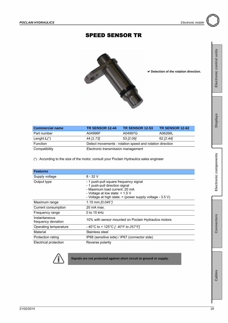
SPEED SENSOR TR
Commercial name TR SENSOR 12-44 TR SENSOR 12-53 TR SENSOR 12-62
Part number A04996F A04997G A06266L
Lenght L(*) 44 [1.73] 53 [2.09] 62 [2.44]
Function Detect movements : rotation speed and rotation direction
Compatibility Electronic transmission management
(*) : According to the size of the motor, consult your Poclain Hydraulics sales engineer
Features
Supply voltage 8 - 32 V
Output type - 1 push-pull square frequency signal- 1 push-pull direction signal- Maximum load current: 20 mA- Voltage at low state: < 1.5 V- Voltage at high state: > (power supply voltage - 3.5 V)
Maximum range 1.15 mm [0.045’’]
Current consumption 20 mA max.
Frequency range 0 to 15 kHz
Instantaneous frequency deviation
10% with sensor mounted on Poclain Hydraulics motors
Operating temperature - 40°C to + 125°C [- 40°F to 257°F]
Material Stainless steel
Protection rating IP68 (sensitive side) / IP67 (connector side)
Electrical protection Reverse polarity
Signals are not protected against short circuit to ground or supply.
Detection of the rotation direction.

26 21/02/2014
Electronic mobile POCLAIN HYDRAULICS
Layout
Installation
Disconnecting the accessories and speed set up
In the case of motors predisposed to speed, the existing shutter needs to be removed and eliminated before installing the sensor and its attachment device.
To install the sensor, see the ''Installation guide'' brochure No. 801478197L.
Connection of the speed sensor
Remove the plastic plug on the connector.
Function Pin number
Power supply 1
Direction signal 2
Ground 3
Square frequency signal 4
For the connection of connectors, please refer to the connection table and the general cabling plan contained in the installation brochure for your transmission.
Electrical connections 90° 180°
Commercial name ELEC-CABLE-M12-90°-5000 ELEC-CABLE-M12-180°-5000
Part number A04999J A07468S
page 87 page 87
21/02/2014 27
POCLAIN HYDRAULICS Electronic mobile
Ele
ctr
on
ic c
on
tro
l u
nit
sE
lect
ron
ic c
om
po
nen
tsC
on
nec
tors
Cab
les
Dis
pla
ys
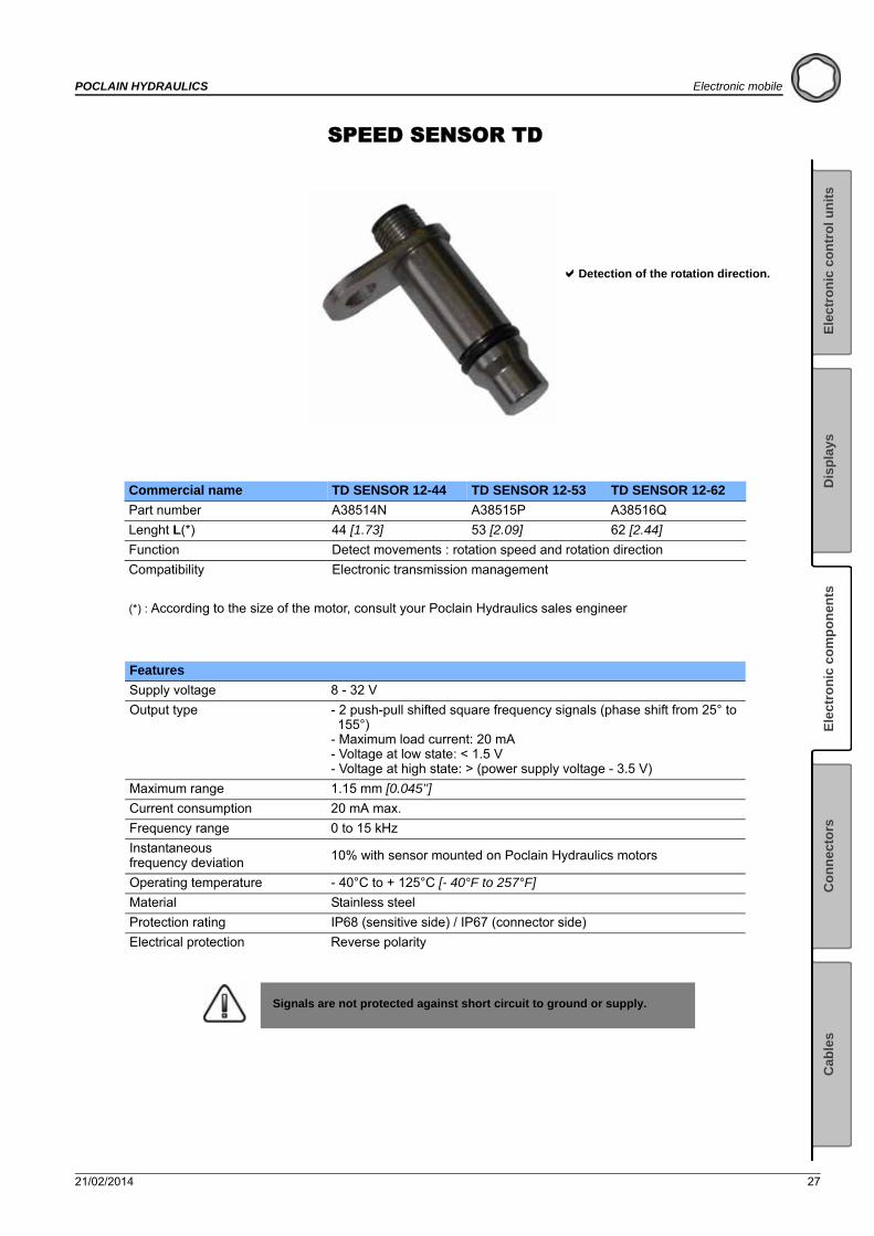
SPEED SENSOR TD
Commercial name TD SENSOR 12-44 TD SENSOR 12-53 TD SENSOR 12-62
Part number A38514N A38515P A38516Q
Lenght L(*) 44 [1.73] 53 [2.09] 62 [2.44]
Function Detect movements : rotation speed and rotation direction
Compatibility Electronic transmission management
(*) : According to the size of the motor, consult your Poclain Hydraulics sales engineer
Features
Supply voltage 8 - 32 V
Output type - 2 push-pull shifted square frequency signals (phase shift from 25° to 155°)
- Maximum load current: 20 mA- Voltage at low state: < 1.5 V- Voltage at high state: > (power supply voltage - 3.5 V)
Maximum range 1.15 mm [0.045’’]
Current consumption 20 mA max.
Frequency range 0 to 15 kHz
Instantaneous frequency deviation
10% with sensor mounted on Poclain Hydraulics motors
Operating temperature - 40°C to + 125°C [- 40°F to 257°F]
Material Stainless steel
Protection rating IP68 (sensitive side) / IP67 (connector side)
Electrical protection Reverse polarity
Signals are not protected against short circuit to ground or supply.
Detection of the rotation direction.
28 21/02/2014
Electronic mobile POCLAIN HYDRAULICS
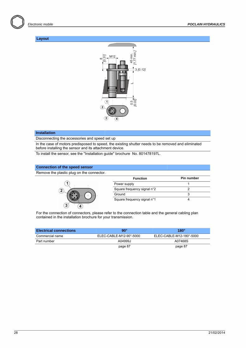
Layout
Installation
Disconnecting the accessories and speed set up
In the case of motors predisposed to speed, the existing shutter needs to be removed and eliminated before installing the sensor and its attachment device.
To install the sensor, see the ''Installation guide'' brochure No. 801478197L.
Connection of the speed sensor
Remove the plastic plug on the connector.
Function Pin number
Power supply 1
Square frequency signal n°2 2
Ground 3
Square frequency signal n°1 4
For the connection of connectors, please refer to the connection table and the general cabling plan contained in the installation brochure for your transmission.
Electrical connections 90° 180°
Commercial name ELEC-CABLE-M12-90°-5000 ELEC-CABLE-M12-180°-5000
Part number A04999J A07468S
page 87 page 87

21/02/2014 29
POCLAIN HYDRAULICS Electronic mobile
Ele
ctr
on
ic c
on
tro
l u
nit
sE
lect
ron
ic c
om
po
nen
tsC
on
nec
tors
Cab
les
Dis
pla
ys
MAGNETIC INCREMENTAL HOLLOW SHAFT ENCODER
Commercial name ENCODER-HOLLOW-3600-12-2000
Part number A38403S
Hydraulic motors compatibility MS18; MS35; MK35; MK47*
Function Detect movements : rotation speed and rotation direction
Compatibility Electronic transmission management
* In case of request for another motors, please contact your Poclain Hydraulics application engineer in matter of feasibility.
General Features
Power supply voltage (+Vs) 10 - 30 VDC
Number of pulses per revolution 3600
Frequency dither ± 15%
Supply current (no load) 15 mA at 24 VDC
Output type Push-pull
Max output current 30 mA per channel
Low level max 2,5 V
High level min +Vs - 3,7 V
Switching frequency 320 kHz max
Electrical protection short circuit and reverse polarity
Mechanical Features
Max revolutions 6000 rpm
Protection IP65
Material aluminium
Operating temperature -20°C to +85°C [-4°F to 185°F]
Ambient conditions
Vibration (sine) IEC 60068-2-6 (<= 300 m/s2 / 10 - 2000 Hz)
Vibration (random) IEC 60068-2-64 (<= 0,1 g2/Hz / 20 - 2000 Hz)
Shock IEC 60068-2-27 (<= 1000 m/s2 / 6 ms)
Bump IEC 60068-2-29 (<= 1000 m/s2 / 2 ms)
EMC immunity EN 61000-6-2
EMC emission EN 61000-6-3
High resolution
30 21/02/2014
Electronic mobile POCLAIN HYDRAULICS
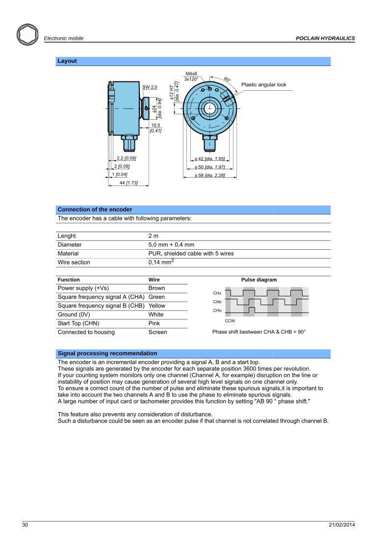
Layout
Connection of the encoder
The encoder has a cable with following parameters:
Lenght 2 m
Diameter 5,0 mm + 0,4 mm
Material PUR, shielded cable with 5 wires
Wire section 0,14 mm2
Function Wire Pulse diagram
Power supply (+Vs) Brown
Square frequency signal A (CHA) Green
Square frequency signal B (CHB) Yellow
Ground (0V) White
Start Top (CHN) Pink
Connected to housing Screen Phase shift beetween CHA & CHB = 90°
Signal processing recommendation
The encoder is an incremental encoder providing a signal A, B and a start top.These signals are generated by the encoder for each separate position 3600 times per revolution.If your counting system monitors only one channel (Channel A, for example) disruption on the line or instability of position may cause generation of several high level signals on one channel only.To ensure a correct count of the number of pulse and eliminate these spurious signals,it is important to take into account the two channels A and B to use the phase to eliminate spurious signals.A large number of input card or tachometer provides this function by setting "AB 90 ° phase shift." This feature also prevents any consideration of disturbance.Such a disturbance could be seen as an encoder pulse if that channel is not correlated through channel B.
24
[dia
. 0.9
4]
10,5[0.41]
SW 2,0
2,2 [0.09]
2 [0.08]
1 [0.04]
44 [1.73]
M4x83x120°
12 H
7 [d
ia. 0
.47]
50 [dia. 1.97]
58 [dia. 2.28]
42 [dia. 1.65]
60°Plastic angular lock
CHA
CHB
CHN
CCW
21/02/2014 31
POCLAIN HYDRAULICS Electronic mobile
Ele
ctr
on
ic c
on
tro
l u
nit
sE
lect
ron
ic c
om
po
nen
tsC
on
nec
tors
Cab
les
Dis
pla
ys
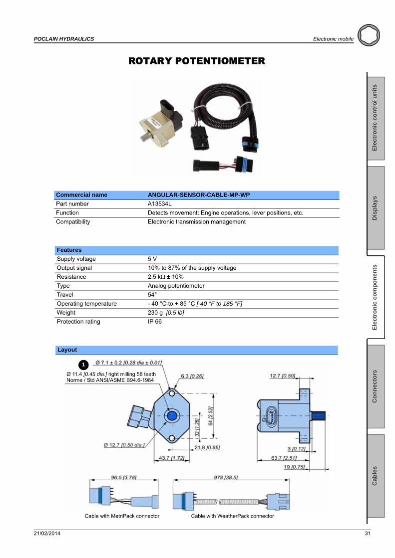
ROTARY POTENTIOMETER
Commercial name ANGULAR-SENSOR-CABLE-MP-WP
Part number A13534L
Function Detects movement: Engine operations, lever positions, etc.
Compatibility Electronic transmission management
Features
Supply voltage 5 V
Output signal 10% to 87% of the supply voltage
Resistance 2.5 k± 10%
Type Analog potentiometer
Travel 54°
Operating temperature - 40 °C to + 85 °C [-40 °F to 185 °F]
Weight 230 g [0.5 lb]
Protection rating IP 66
Layout
1
Ø 11.4 [0.45 dia.] right milling 58 teethNorme / Std ANSI/ASME B94.6-1984
Cable with MetriPack connector Cable with WeatherPack connector
32 21/02/2014
Electronic mobile POCLAIN HYDRAULICS
Installation
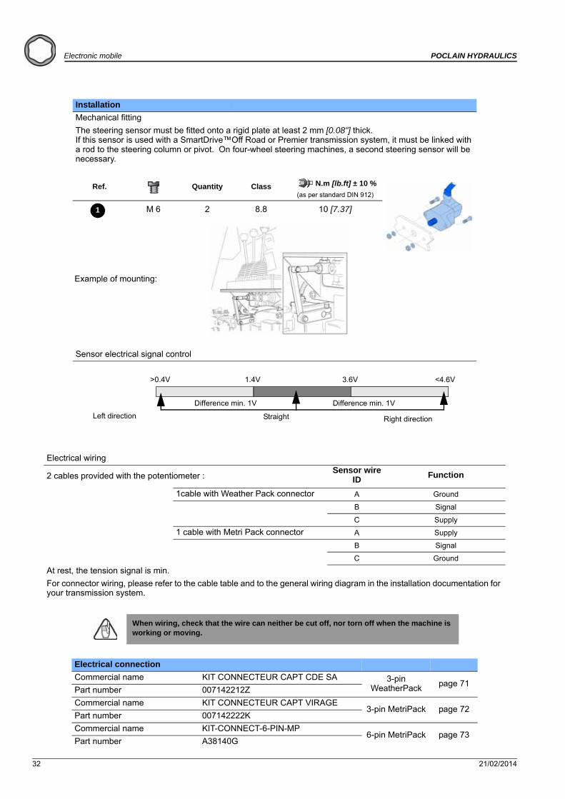
Mechanical fitting
The steering sensor must be fitted onto a rigid plate at least 2 mm [0.08"] thick.If this sensor is used with a SmartDrive™Off Road or Premier transmission system, it must be linked with a rod to the steering column or pivot. On four-wheel steering machines, a second steering sensor will be necessary.
Ref. Quantity Class N.m [lb.ft] ± 10 %
(as per standard DIN 912)
M 6 2 8.8 10 [7.37]
Example of mounting:
Sensor electrical signal control
Electrical wiring
2 cables provided with the potentiometer :Sensor wire
ID Function
1cable with Weather Pack connector A Ground
B Signal
C Supply
1 cable with Metri Pack connector A Supply
B Signal
C Ground
At rest, the tension signal is min.
For connector wiring, please refer to the cable table and to the general wiring diagram in the installation documentation for your transmission system.
When wiring, check that the wire can neither be cut off, nor torn off when the machine is working or moving.
Electrical connection
Commercial name KIT CONNECTEUR CAPT CDE SA 3-pin WeatherPack page 71
Part number 007142212Z
Commercial name KIT CONNECTEUR CAPT VIRAGE3-pin MetriPack page 72
Part number 007142222K
Commercial name KIT-CONNECT-6-PIN-MP6-pin MetriPack page 73
Part number A38140G
1
Difference min. 1V
Left direction Straight Right direction
Difference min. 1V
>0.4V <4.6V3.6V1.4V

21/02/2014 33
POCLAIN HYDRAULICS Electronic mobile
Ele
ctr
on
ic c
on
tro
l u
nit
sE
lect
ron
ic c
om
po
nen
tsC
on
nec
tors
Cab
les
Dis
pla
ys
20 BAR PRESSURE SENSOR
Commercial name PRES-SENSOR-20B-OT1-G1/4
Part number A21362U
Function Measure the case pressure
Compatibility Electronic transmission management
Features
Power supply 5 V ± 0.5 V
Output signal 0.5V to 4.5V ratiometric
Pressure range 20 bars [290 PSI]
Over pressure safety 50 bars [725 PSI]
Pressure connection G1/4"
Response time 2 ms
Accuracy 1% FS
Using temperature range Medium - 40 °C to 125 °C [- 40 °F to 257 °F]
Ambient - 40 °C to 100 °C [- 40 °F to 212 °F]
Storage - 40 °C to 120 °C [- 40 °F to 248 °F]
Ingress protection IP 67
CE conformity EN 61326
Shock resistance 500 g according to DIN EN 837
Vibration resistance 20 g according to IEC 68-2
20 bar
4,5 V
0,5 V

34 21/02/2014
Electronic mobile POCLAIN HYDRAULICS
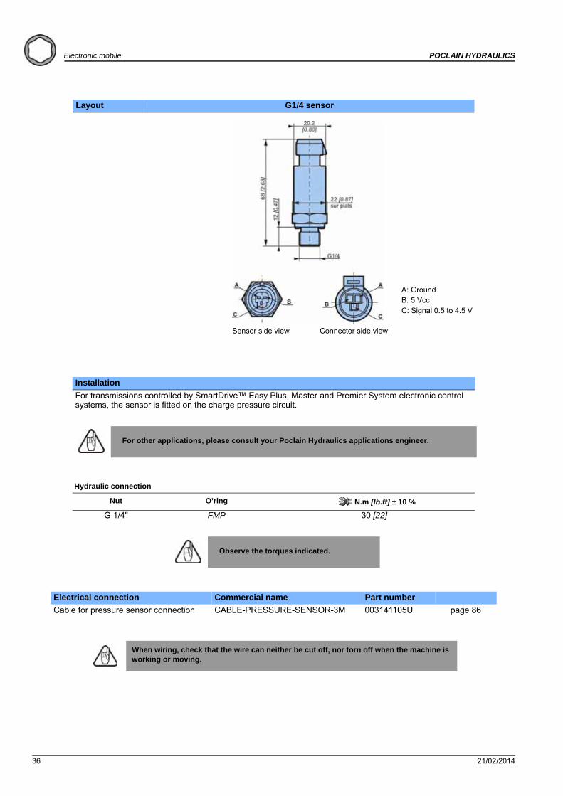
Layout G1/4 sensor
Installation
For transmissions controlled by SmartDrive™ Easy Plus, Master and Premier System electronic control systems, the sensor is fitted on the case motor pressure circuit.
For other applications, please consult your Poclain Hydraulics applications engineer.
Hydraulic connection
Nut O’ring N.m [lb.ft] ± 10 %
G 1/4" FMP 30 [22]
Observe the torques indicated.
Electrical connection Commercial name Part number
Cable for pressure sensor connection CABLE-PRESSURE-SENSOR-3M 003141105U page 86
When wiring, check that the wire can neither be cut off, nor torn off when the machine is working or moving.
A: GroundB: 5 VccC: Signal 0.5 to 4.5 V
Connector side viewSensor side view
21/02/2014 35
POCLAIN HYDRAULICS Electronic mobile
Ele
ctr
on
ic c
on
tro
l u
nit
sE
lect
ron
ic c
om
po
nen
tsC
on
nec
tors
Cab
les
Dis
pla
ys
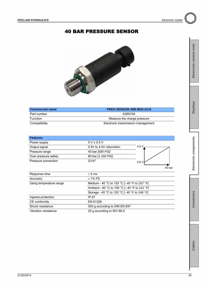
40 BAR PRESSURE SENSOR
Commercial name PRES-SENSOR-40B-MH2-G1/4
Part number A36915A
Function Measure the charge pressure
Compatibility Electronic transmission management
Features
Power supply 5 V ± 0.5 V
Output signal 0.5V to 4.5V ratiometric
Pressure range 40 bar [580 PSI]
Over pressure safety 80 bar [1 160 PSI]
Pressure connection G1/4"
Response time 5 ms
Accuracy 1% FS
Using temperature range Medium - 40 °C to 125 °C [- 40 °F to 257 °F]
Ambient - 40 °C to 100 °C [- 40 °F to 212 °F]
Storage - 40 °C to 120 °C [- 40 °F to 248 °F]
Ingress protection IP 67
CE conformity EN 61326
Shock resistance 500 g according to DIN EN 837
Vibration resistance 20 g according to IEC 68-2
40 bar
4,5 V
0,5 V
36 21/02/2014
Electronic mobile POCLAIN HYDRAULICS
Layout G1/4 sensor
Installation
For transmissions controlled by SmartDrive™ Easy Plus, Master and Premier System electronic control systems, the sensor is fitted on the charge pressure circuit.
For other applications, please consult your Poclain Hydraulics applications engineer.
Hydraulic connection
Nut O’ring N.m [lb.ft] ± 10 %
G 1/4" FMP 30 [22]
Observe the torques indicated.
Electrical connection Commercial name Part number
Cable for pressure sensor connection CABLE-PRESSURE-SENSOR-3M 003141105U page 86
When wiring, check that the wire can neither be cut off, nor torn off when the machine is working or moving.
A: GroundB: 5 VccC: Signal 0.5 to 4.5 V
Connector side viewSensor side view

21/02/2014 37
POCLAIN HYDRAULICS Electronic mobile
Ele
ctr
on
ic c
on
tro
l u
nit
sE
lect
ron
ic c
om
po
nen
tsC
on
nec
tors
Cab
les
Dis
pla
ys
160 BAR PRESSURE SENSOR
Commercial name PRES-SENSOR-160B-MH2-M10 PRES-SENSOR-160B-MH2-G1/4
Part number 003241167H 003241164E
Function Measure the pressure on the brake system
Compatibility Electronic transmission management
Features
Power supply 5 V ± 0.5 V
Output signal 0.5V to 4.5V ratiometric
Pressure range 160 bars [2320 PSI]
Over pressure safety 320 bars [4640 PSI]
Pressure connection with VITON rectangulare section seal
M10 x 1 - G1/4"
Response time 5 ms
Accuracy 1% FS
Using temperature range Medium - 40 °C to 125 °C [- 40 °F to 257 °F]
Ambient - 40 °C to 100 °C [- 40 °F to 212 °F]
Storage - 40 °C to 120 °C [- 40 °F to 248 °F]
Ingress protection IP 67
CE conformity EN 61326
Shock resistance 500 g according to DIN EN 837
Vibration resistance 20 g according to IEC 68-2
160 bar
4,5 V
0,5 V
38 21/02/2014
Electronic mobile POCLAIN HYDRAULICS
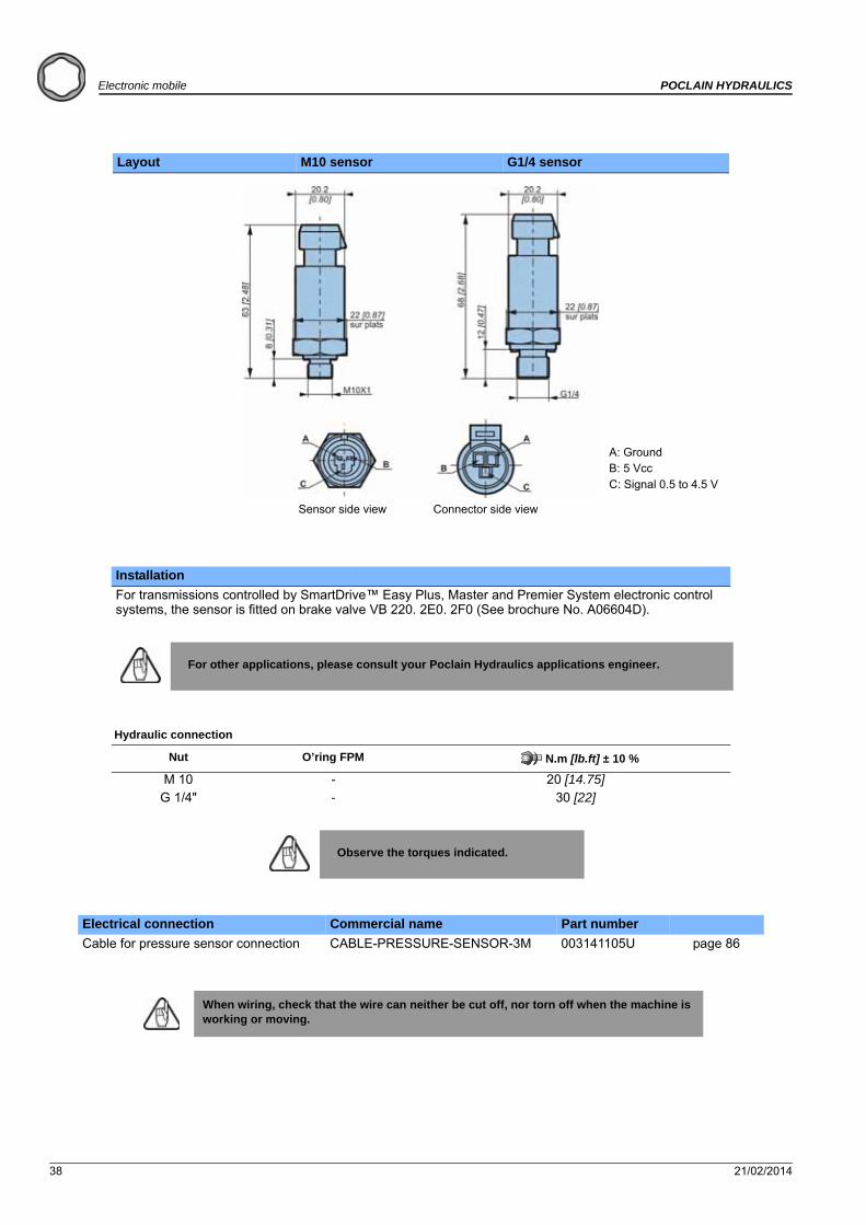
Layout M10 sensor G1/4 sensor
Installation
For transmissions controlled by SmartDrive™ Easy Plus, Master and Premier System electronic control systems, the sensor is fitted on brake valve VB 220. 2E0. 2F0 (See brochure No. A06604D).
For other applications, please consult your Poclain Hydraulics applications engineer.
Hydraulic connection
Nut O’ring FPM N.m [lb.ft] ± 10 %
M 10 - 20 [14.75]G 1/4" - 30 [22]
Observe the torques indicated.
Electrical connection Commercial name Part number
Cable for pressure sensor connection CABLE-PRESSURE-SENSOR-3M 003141105U page 86
When wiring, check that the wire can neither be cut off, nor torn off when the machine is working or moving.
Sensor side view Connector side view
A: GroundB: 5 VccC: Signal 0.5 to 4.5 V

21/02/2014 39
POCLAIN HYDRAULICS Electronic mobile
Ele
ctr
on
ic c
on
tro
l u
nit
sE
lect
ron
ic c
om
po
nen
tsC
on
nec
tors
Cab
les
Dis
pla
ys
600 BAR PRESSURE SENSOR
Commercial name PRES-SENSOR-600B-MH2-9/16 PRES-SENSOR-600B-MH2-G1/4
Part number 003241170L 003241171M
Function Measure the pressure on the High Pressure system
Compatibility Electronic transmission management
Features
Power supply 5 V ± 0.5 V
Output signal 0.5V to 4.5V ratiometric
Pressure range 600 bars [8702 PSI]
Over pressure safety 1200 bars [16800 PSI]
Pressure connection with O’ring 9/16" - G 1/4"
Response time 5 ms
Accuracy 1% FS
Using temperature range Medium - 40 °C to 125 °C [- 40 °F to 257 °F]
Ambient - 40 °C to 100 °C [- 40 °F to 212 °F]
Storage - 40 °C to 120 °C [- 40 °F to 248 °F]
Ingress protection IP 67
CE conformity EN 61326
Shock resistance 500 g according to DIN EN 837
Vibration resistance 20 g according to IEC 68-2
600 bar
4,5 V
0,5 V
40 21/02/2014
Electronic mobile POCLAIN HYDRAULICS
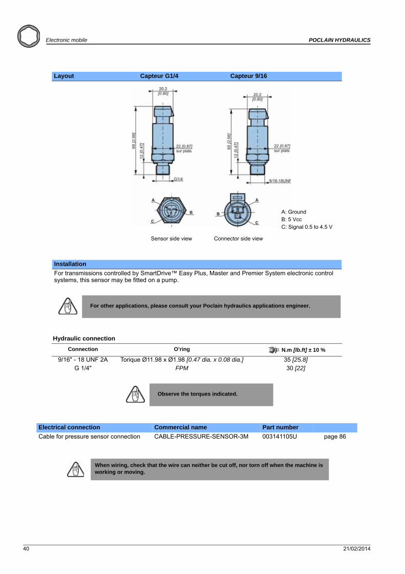
Layout Capteur G1/4 Capteur 9/16
Installation
For transmissions controlled by SmartDrive™ Easy Plus, Master and Premier System electronic control systems, this sensor may be fitted on a pump.
For other applications, please consult your Poclain hydraulics applications engineer.
Hydraulic connection
Connection O’ring N.m [lb.ft] ± 10 %
9/16" - 18 UNF 2A Torique Ø11.98 x Ø1.98 [0.47 dia. x 0.08 dia.] 35 [25.8]G 1/4" FPM 30 [22]
Observe the torques indicated.
Electrical connection Commercial name Part number
Cable for pressure sensor connection CABLE-PRESSURE-SENSOR-3M 003141105U page 86
When wiring, check that the wire can neither be cut off, nor torn off when the machine is working or moving.
Sensor side view Connector side view
A: GroundB: 5 VccC: Signal 0.5 to 4.5 V

21/02/2014 41
POCLAIN HYDRAULICS Electronic mobile
Ele
ctr
on
ic c
on
tro
l u
nit
sE
lect
ron
ic c
om
po
nen
tsC
on
nec
tors
Cab
les
Dis
pla
ys
DIGITAL SENSORS
Commercial name DETECTEUR TOR M18 CABLE DETECTEUR TOR M18 CONNECT
Part number 003241160A 003241159Z
Function Detects movement
Compatibility Electronic transmission management
Features
Supply voltage 10 to 30 V
Nominal range 8 mm [0.31]
Guaranteed detection distance until6.48 mm [0.25]
Maximum switching frequency 500 Hz
Supply current 0 to 200 mA
Offload consumption 15 mA
Maximum charging current 200 mA
Max. voltage drop 3 V
Voltage drop (charge 20 mA) < to 1.5 V
Operating temperature -25°c to 70°c [-13 °F to 158 °F]
Housing material Brass
Ingress protection IP 67
Electrical protectionAgainst short-circuitsAgainst polarity inversion

42 21/02/2014
Electronic mobile POCLAIN HYDRAULICS
Layout Sensor with cable Sensor with connector
Installation of the digital steering sensor
The steering sensor must be secured (with the 2 screws supplied) on a rigid sheet at least 2 mm thick.
Example of mounting
N.m [lb.ft] ± 10 %
30 [22.1]
The steering sensor must be secured (with the 2 screws supplied) on a rigid sheet at least 2 mm thick.
Example of mounting
Pin Color Description
1 Brown Supply
4 Black Signal
3 Blue Ground
Electrical connection 90° 180°
Commercial name ELEC-CABLE-M12-90°-5000 ELEC-CABLE-M12-180°-5000
Part No. A04999J A07468S
page 87 page 87
When wiring, check that the wire can neither be cut off, nor torn off when the machine is working or moving.
Delivered with 2 nuts, 4 mm (not fitted) Delivered with 2 nuts, 4 mm (not fitted)
Lock-nut
NutWheel
Cylinder
Disc detected
L = 2m (3 wires x 0.34mm²)

21/02/2014 43
POCLAIN HYDRAULICS Electronic mobile
Ele
ctr
on
ic c
on
tro
l u
nit
sE
lect
ron
ic c
om
po
nen
tsC
on
nec
tors
Cab
les
Dis
pla
ys
ANALOG TEMPERATURE SENSORS
Commercial name TEMP-SENSOR-ANALOG-G1/4-M12 TEMP-SENSOR-G1/4-M12-53
Part number A22147X A37774J
Compatibility Electronic transmission management
Fonction Measure the temperature of the hydraulic circuit
Features
Power supply 5V ± 0.5 V
Output signal0.5 V to 4.5 V radiometricSaturation at 0.4 V for temperatures < -23°C [-9.4°F]
Response time 5 s
Accuracy ±1.5% FS from -20°C [-4°F] to 0°C [32°F]±1% FS from 0°C [32°F] to 120°C [248°F]
Permissible pressure 750 bar [10 877 PSI]
Using temperature range -20 to +120°C [-4 to +248°F]
Housing material Inox 304
Ingress protection IP67
Electrical protection- Over voltage: 30 V- Reverse polarity,- Short circuit.
Shock resistance 1m 3 axes
Vibration resistance 20 g
Mounting
To obtain a good temperature reading put the sensitive part of the sensor in the heart of the fluid stream.
Two lengths of sensor are available (19 mm [0.75 in] and 53 mm [2.09 in]) to achieve the best mounting for your application.
120-20
4,5
0,5
-23
0,4
V
°C

44 21/02/2014
Electronic mobile POCLAIN HYDRAULICS
Layout
TEMP-SENSOR-ANALOG-G1/4-M12 TEMP-SENSOR-G1/4-M12-53
Hydraulic connection
Connection O’ring N.m [lb.ft] ± 10 %
G 1/4" Viton 22,5 [16.6]
Electrical connection 90° 180°
Commercial name ELEC-CABLE-M12-90°-5000 ELEC-CABLE-M12-180°-5000
Part No. A04999J A07468S
page 87 page 87
When wiring, check that the wire can neither be cut off, nor torn off when the machine is working or moving.
SW24
1 = nc2 = +5 V3 = Output signal 0.5 to 4.5 V4 = 0 V (Ground)
SW24

21/02/2014 45
POCLAIN HYDRAULICS Electronic mobile
Ele
ctr
on
ic c
on
tro
l u
nit
sE
lect
ron
ic c
om
po
nen
tsC
on
nec
tors
Cab
les
Dis
pla
ys
TEMPERATURE SWITCH
Commercial name TEMP-SENSOR-M14-95C-NC TEMP-SENSOR-9/16-95C-NC
Part number A22073S A22572K
Compatibility Electronic transmission management
Fonction Measure the temperature of the hydraulic circuit
Features
Threshold of temperature 95°C ± 3 [203°F± 37.4]
Hysteresis < 20°C [68°F]
Type of contact switch opens with increasing temperature
Max. voltage 30 Volt
Max. current Ohmic load 16A and inductive load 10A
Using temperature range -40 to +130°C [-40 to +266°F]
Max. pressure 100 bar [1 450 PSI]
Ingress protection IP67
Housing material CuZn38Pb2

46 21/02/2014
Electronic mobile POCLAIN HYDRAULICS
Layout 9/16’’UNF M14
Hydraulic connection
Connection O’ring N.m [lb.ft] ± 10 %
M14 x 1,5 -20 [14.7]
9/16’’ UNF -
Electrical connection
Terminal blades 6,3 x 0,8 [0.25 x 0.03]
When wiring, check that the wire can neither be cut off, nor torn off when the machine is working or moving.

21/02/2014 47
POCLAIN HYDRAULICS Electronic mobile
Ele
ctr
on
ic c
on
tro
l u
nit
sE
lect
ron
ic c
om
po
nen
tsC
on
nec
tors
Cab
les
Dis
pla
ys
JOYSTICK WITH CENTER LOCK
Commercial name JOYSTICK-35°-HANDLE-LOCK
Part number 003442799X
Compatibility Electronic transmission management
FunctionJoystick with medium lock. Provide the translation speed setting.
Joystick is provided with16 pin AMP Multilock connector (see the picture above).
Joystick features
Supply voltage 5 V
Output signal 10% to 90% of supply voltage
Resistance 2k Ohm Tolerance ±20%
Expected service life 500 000 cycles
Electrical stroke ± 32°
Mechanical stroke ± 35°
Maximum applied force 300 N full deflection, 130 mm from flange
Operating force 17.8 N full deflection, 55 mm from flange
Breakout force 6.2 N, 55 mm from flange
Directional switches communication angle 5° ± 1° either side of center
Direction switches max. load current 200 mA resistive
Operating temperature range - 25 °C to + 70 °C [- 13 °F to 158 °F]
Mass 560 g [1.23 lb] with HKN handle fitted
Ingress protection IP 65
Connector features
Manufacturer AMP
ComponentsConnector 174046-2
16 pins 175062-1
Wire range 0.3 to 0.56 mm2
Wire insulation diameter 1.8 to 2 mm
Mounting tools Reference AMP
Chuck-jaw + crimpers 58522-1
48 21/02/2014
Electronic mobile POCLAIN HYDRAULICS
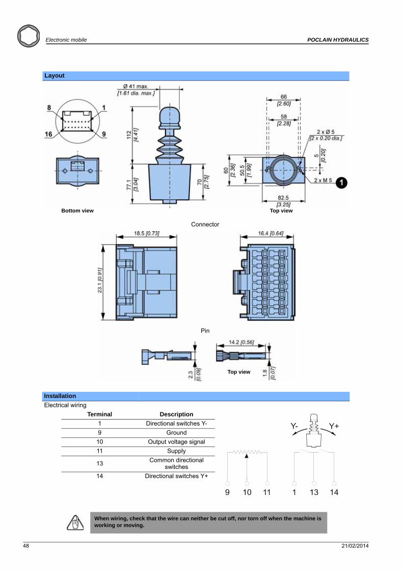
Layout
Installation
Electrical wiring
Terminal Description
1 Directional switches Y-
9 Ground
10 Output voltage signal
11 Supply
13 Common directional switches
14 Directional switches Y+
When wiring, check that the wire can neither be cut off, nor torn off when the machine is working or moving.
Bottom view Top view
Connector
Top view
Pin
21/02/2014 49
POCLAIN HYDRAULICS Electronic mobile
Ele
ctr
on
ic c
on
tro
l u
nit
sE
lect
ron
ic c
om
po
nen
tsC
on
nec
tors
Cab
les
Dis
pla
ys
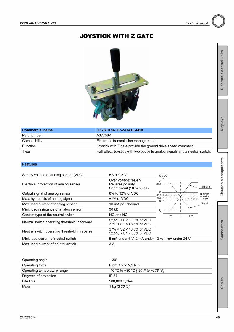
JOYSTICK WITH Z GATE
Commercial name JOYSTICK-30°-Z-GATE-M10
Part number A37706K
Compatibility Electronic transmission management
Function Joystick with Z gate provide the ground drive speed command.
Type Hall Effect Joystick with two opposite analog signals and a neutral switch.
Features
Supply voltage of analog sensor (VDC) 5 V ± 0,5 V
Electrical protection of analog sensorOver voltage: 14.4 VReverse polarityShort circuit (10 minutes)
Output signal of analog sensor 8% to 92% of VDC
Max. hysteresis of analog signal ±1% of VDC
Max. load current of analog sensor 10 mA per channel
Mini. load resistance of analog sensor 30 kΩ
Contact type of the neutral switch NO and NC
Neutral switch operating threshold in forward52,5% < S2 < 63% of VDC37% < S1 < 48,5% of VDC
Neutral switch operating threshold in reverse 37% < S2 < 48,5% of VDC52,5% < S1 < 63% of VDC
Mini. load current of neutral switch 5 mA under 6 V; 2 mA under 12 V; 1 mA under 24 V
Max. load current of neutral switch 3 A
Operating angle ± 30°
Operating force From 1,2 to 2,3 Nm
Operating temperature range -40 °C to +80 °C [-40°F to +176 °F]
Degrees of protection IP 67
Life time 500,000 cycles
Mass 1 kg [2.20 lb]
% VDC
118
3748,552,5
63
88,592
Signal 2
Signal 1
RV N FW
N-switchactuation
range
50 21/02/2014
Electronic mobile POCLAIN HYDRAULICS
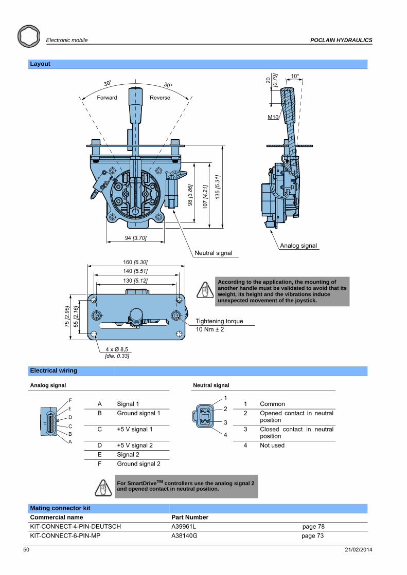
Layout
Electrical wiring
Analog signal Neutral signal
A Signal 1 1 Common
B Ground signal 1 2 Opened contact in neutralposition
C +5 V signal 1 3 Closed contact in neutralposition
D +5 V signal 2 4 Not used
E Signal 2
F Ground signal 2
For SmartDriveTM controllers use the analog signal 2 and opened contact in neutral position.
Mating connector kit
Commercial name Part Number
KIT-CONNECT-4-PIN-DEUTSCH A39961L page 78
KIT-CONNECT-6-PIN-MP A38140G page 73
10°30° 30°
94 [3.70]
107
[4.2
1]
135
[5.3
1]
98 [3
.86]
130 [5.12]
140 [5.51]160 [6.30]
55 [2
.16]
75 [2
.95]
4 x Ø 8,5 [dia. 0.33]
20[0
.79]
M10
Tightening torque10 Nm ± 2
Forward Reverse
Neutral signalAnalog signal
According to the application, the mounting of another handle must be validated to avoid that its weight, its height and the vibrations induce unexpected movement of the joystick.
F E
D
CBA
1
2
3
4
21/02/2014 51
POCLAIN HYDRAULICS Electronic mobile
Ele
ctr
on
ic c
on
tro
l u
nit
sE
lect
ron
ic c
om
po
nen
tsC
on
nec
tors
Cab
les
Dis
pla
ys
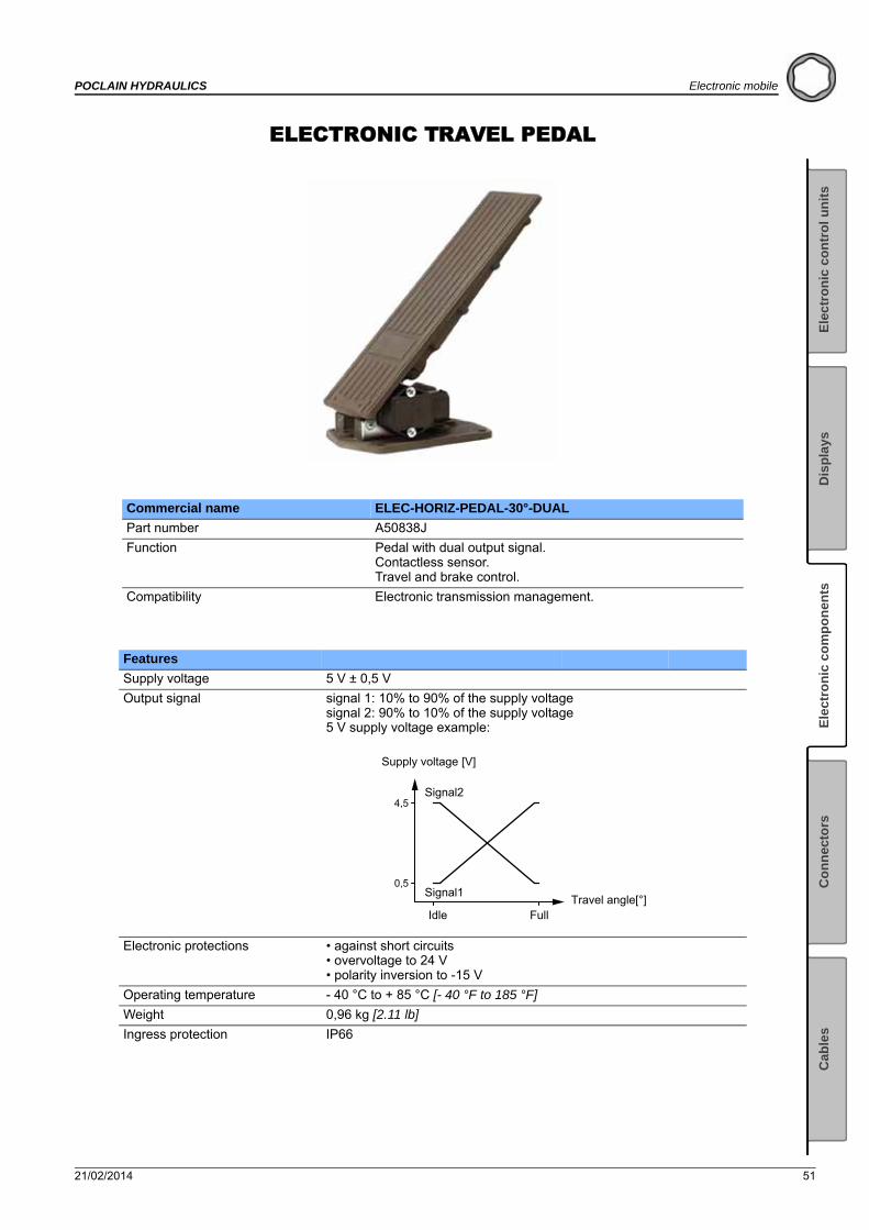
ELECTRONIC TRAVEL PEDAL
Commercial name ELEC-HORIZ-PEDAL-30°-DUAL
Part number A50838J
Function Pedal with dual output signal.Contactless sensor.Travel and brake control.
Compatibility Electronic transmission management.
Features
Supply voltage 5 V ± 0,5 V
Output signal signal 1: 10% to 90% of the supply voltagesignal 2: 90% to 10% of the supply voltage5 V supply voltage example:
Electronic protections • against short circuits• overvoltage to 24 V• polarity inversion to -15 V
Operating temperature - 40 °C to + 85 °C [- 40 °F to 185 °F]
Weight 0,96 kg [2.11 lb]
Ingress protection IP66
4,5
0,5
Signal2
Signal1
Full
Supply voltage [V]
IdleTravel angle[°]
52 21/02/2014
Electronic mobile POCLAIN HYDRAULICS
Electrical connection
Pedal is delivered with a connection kit:
Counter connector kit includes: • Connector• Terminals• Wire seal• Cavity plug
AMP ref. 1-967616-1 (x1)AMP ref. 0-962885-5 (x7)AMP ref. 0-0967067-1 (x7)AMP ref. 967056-1 (x4)
To crimp correctly use:
• Special crimping tool Tyco: 0-0539 635-1 • Wire gauge: AWG20 • External diameter of the wire: between1,29 mm and 1,6 mm
It is possible to connect a harness to use only 1 signal with connector Weather Pack: A51444S (for more details, see page 90).
It is possible to connect a harness to use 2 signals with connector Deutsch: A51445T (for more details, see page 91).
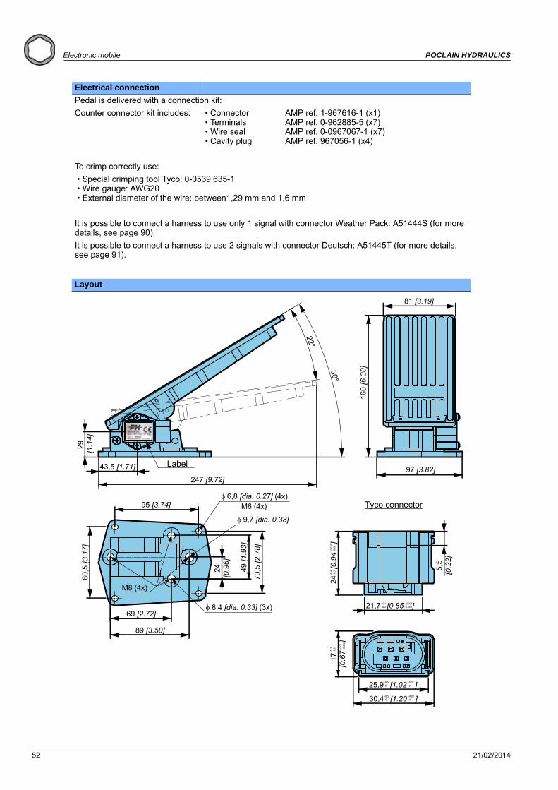
Layout
247 [9.72]
22°
30°
97 [3.82]
81 [3.19]
160
[6.3
0]
43,5 [1.71]
29 [1
.14]
95 [3.74]
80,5
[3.1
7]
89 [3.50]
69 [2.72] 8,4 [dia. 0.33] (3x)
70,5
[2.7
8]
49 [1
.93]
24[0
.96]
6,8 [dia. 0.27] (4x)
9,7 [dia. 0.38]
M6 (4x)
M8 (4x)
25,9 [1.02 ]+0,5 0
+0.02 0
30,4 [1.20 ]+0,5 0
+0.02 0
17
[0.6
7
]
+0,3
-0,2 +0
.01
-0.0
08
24
[0.9
4
]+0
,4 -0
,5+0
.016
-0.0
2
5,5
[0.2
2]
21,7 [0.85 ]+0,1 -0,2
+0.004 -0.008
Tyco connector
Label
21/02/2014 53
POCLAIN HYDRAULICS Electronic mobile
Ele
ctr
on
ic c
on
tro
l u
nit
sE
lect
ron
ic c
om
po
nen
tsC
on
nec
tors
Cab
les
Dis
pla
ys
Installation
Fixing on support:
Sheet thickness must be a minimum of 4 mm [0.16 inch].
The pedal may be fixed on its support in two ways; with either 4x M6 screws, or by 4 x M8 screws (not supplied).
Ref. Quantity Class N.m [lb.ft] ± 10 %(as per standard DIN 912)
M8 4 8.8 25 [18.44]
M6 4 8.8 10 [7.37]
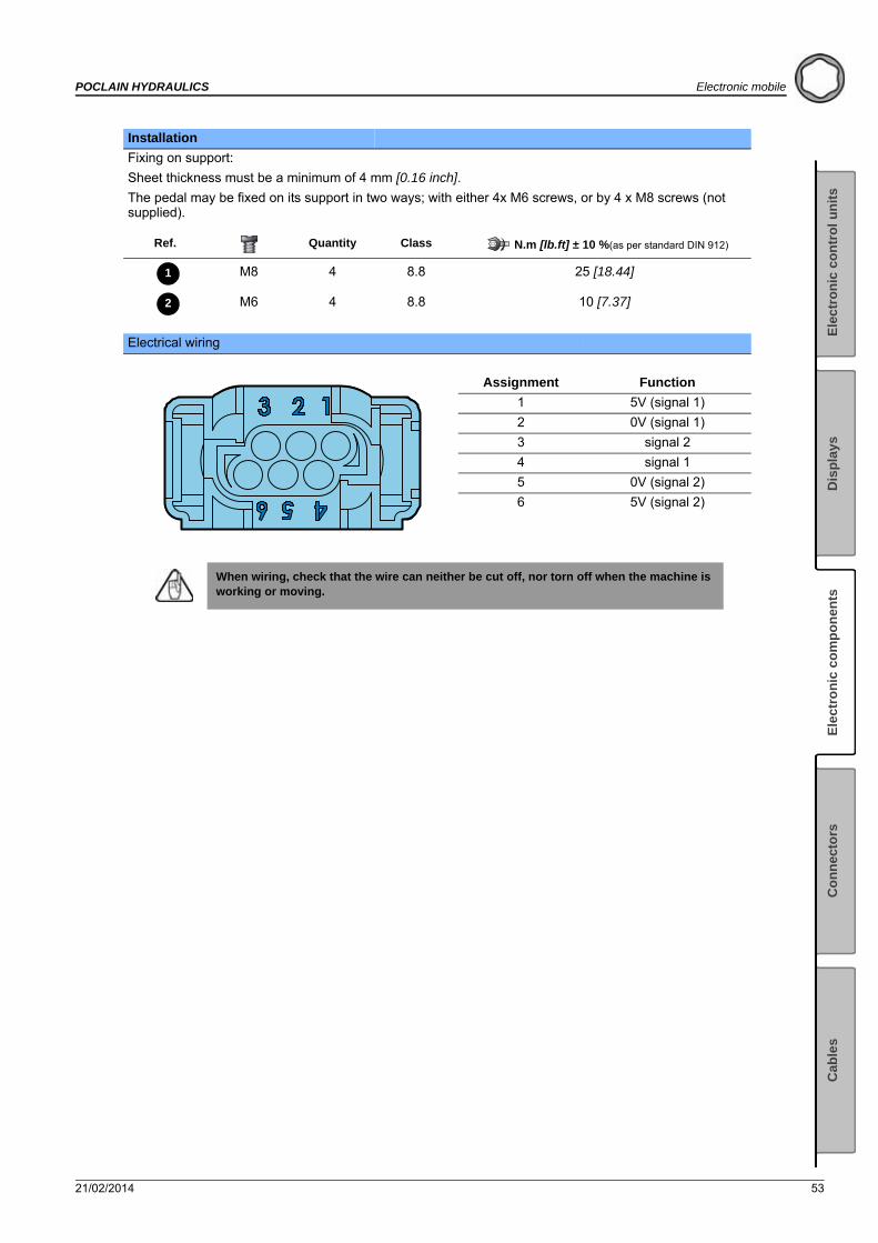
Electrical wiring
Assignment Function
1 5V (signal 1)
2 0V (signal 1)
3 signal 2
4 signal 1
5 0V (signal 2)
6 5V (signal 2)
When wiring, check that the wire can neither be cut off, nor torn off when the machine is working or moving.
1
2

54 21/02/2014
Electronic mobile POCLAIN HYDRAULICS
21/02/2014 55
POCLAIN HYDRAULICS Electronic mobile
Ele
ctr
on
ic c
on
tro
l u
nit
sE
lect
ron
ic c
om
po
nen
tsC
on
nec
tors
Cab
les
Dis
pla
ys
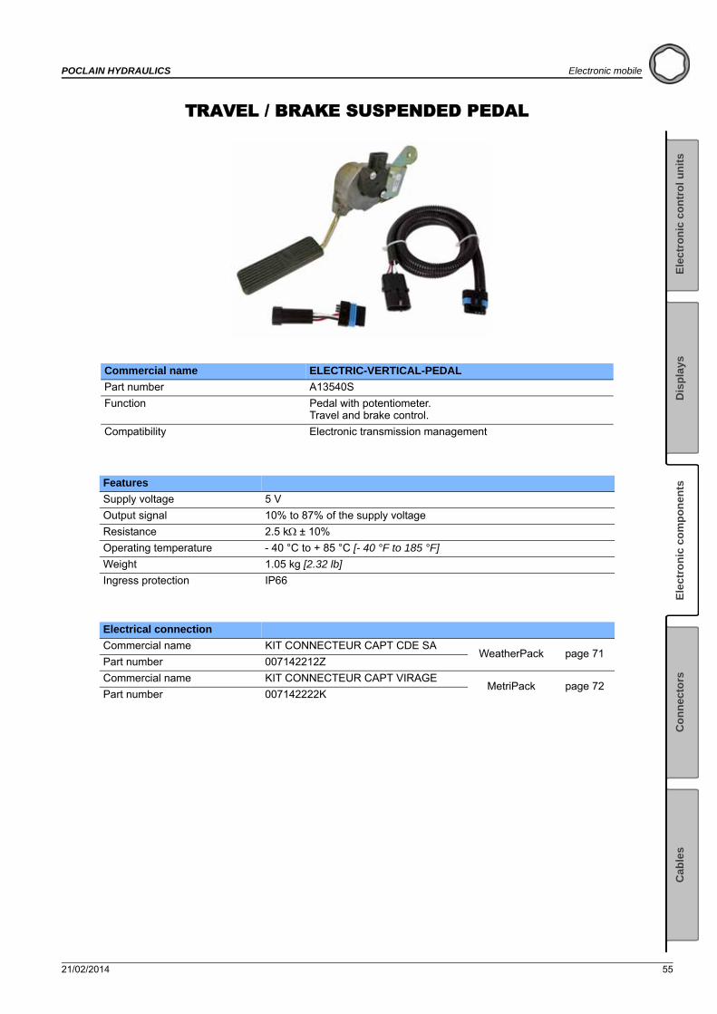
TRAVEL / BRAKE SUSPENDED PEDAL
Commercial name ELECTRIC-VERTICAL-PEDAL
Part number A13540S
Function Pedal with potentiometer.Travel and brake control.
Compatibility Electronic transmission management
Features
Supply voltage 5 V
Output signal 10% to 87% of the supply voltage
Resistance 2.5 k± 10%
Operating temperature - 40 °C to + 85 °C [- 40 °F to 185 °F]
Weight 1.05 kg [2.32 lb]
Ingress protection IP66
Electrical connection
Commercial name KIT CONNECTEUR CAPT CDE SAWeatherPack page 71
Part number 007142212Z
Commercial name KIT CONNECTEUR CAPT VIRAGEMetriPack page 72
Part number 007142222K
56 21/02/2014
Electronic mobile POCLAIN HYDRAULICS
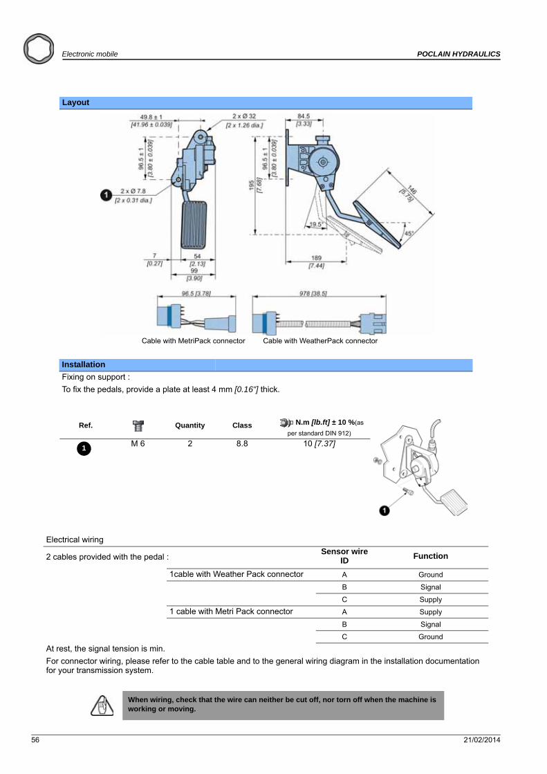
Layout
Installation
Fixing on support :
To fix the pedals, provide a plate at least 4 mm [0.16"] thick.
Ref. Quantity Class N.m [lb.ft] ± 10 %(as
per standard DIN 912)
M 6 2 8.8 10 [7.37]
Electrical wiring
2 cables provided with the pedal :Sensor wire
ID Function
1cable with Weather Pack connector A Ground
B Signal
C Supply
1 cable with Metri Pack connector A Supply
B Signal
C Ground
At rest, the signal tension is min.
For connector wiring, please refer to the cable table and to the general wiring diagram in the installation documentation for your transmission system.
When wiring, check that the wire can neither be cut off, nor torn off when the machine is working or moving.
Cable with MetriPack connector Cable with WeatherPack connector
1
21/02/2014 57
POCLAIN HYDRAULICS Electronic mobile
Ele
ctr
on
ic c
on
tro
l u
nit
sE
lect
ron
ic c
om
po
nen
tsC
on
nec
tors
Cab
les
Dis
pla
ys
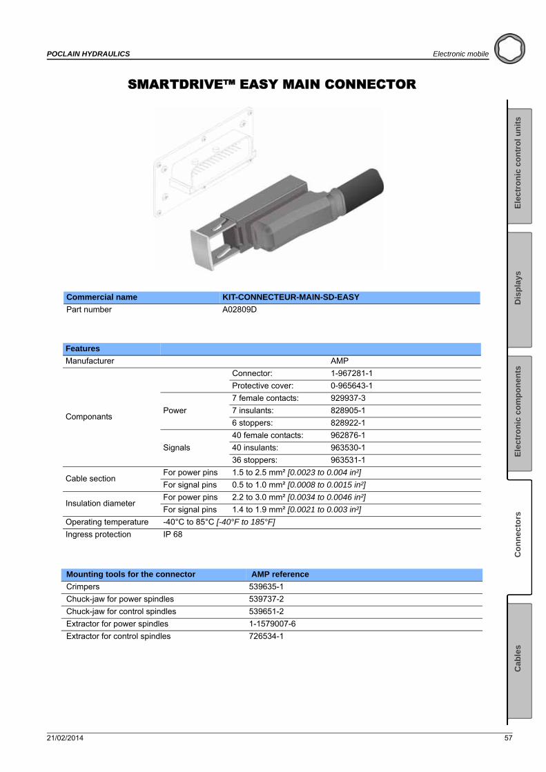
SMARTDRIVE™ EASY MAIN CONNECTOR
Commercial name KIT-CONNECTEUR-MAIN-SD-EASY
Part number A02809D
Features
Manufacturer AMP
Componants
Connector: 1-967281-1
Protective cover: 0-965643-1
Power
7 female contacts: 929937-3
7 insulants: 828905-1
6 stoppers: 828922-1
Signals
40 female contacts: 962876-1
40 insulants: 963530-1
36 stoppers: 963531-1
Cable sectionFor power pins 1.5 to 2.5 mm² [0.0023 to 0.004 in²]
For signal pins 0.5 to 1.0 mm² [0.0008 to 0.0015 in²]
Insulation diameterFor power pins 2.2 to 3.0 mm² [0.0034 to 0.0046 in²]
For signal pins 1.4 to 1.9 mm² [0.0021 to 0.003 in²]
Operating temperature -40°C to 85°C [-40°F to 185°F]
Ingress protection IP 68
Mounting tools for the connector AMP reference
Crimpers 539635-1
Chuck-jaw for power spindles 539737-2
Chuck-jaw for control spindles 539651-2
Extractor for power spindles 1-1579007-6
Extractor for control spindles 726534-1
Connectors

58 21/02/2014
Electronic mobile POCLAIN HYDRAULICS
21/02/2014 59
POCLAIN HYDRAULICS Electronic mobile
Ele
ctr
on
ic c
on
tro
l u
nit
sE
lect
ron
ic c
om
po
nen
tsC
on
nec
tors
Cab
les
Dis
pla
ys
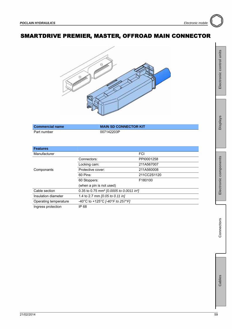
SMARTDRIVE PREMIER, MASTER, OFFROAD MAIN CONNECTOR
Commercial name MAIN SD CONNECTOR KIT
Part number 007142203P
Features
Manufacturer FCI
Componants
Connectors: PPI0001258
Locking cam: 211A567007
Protective cover: 211A560008
60 Pins: 211CC2S1120
60 Stoppers: F180100
(when a pin is not used)
Cable section 0.35 to 0.75 mm² [0.0005 to 0.0011 in²]
Insulation diameter 1.4 to 2.7 mm [0.05 to 0.11 in]
Operating temperature -40°C to +125°C [-40°F to 257°F]
Ingress protection IP 68
60 21/02/2014
Electronic mobile POCLAIN HYDRAULICS
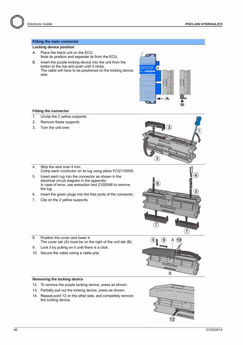
Fitting the main connector
Locking device position
A. Place the black unit on the ECU. Note its position and separate its from the ECU.
B. Insert the purple locking device into the unit from the botton to the top and push until it clicks. The cable will have to be positioned on the locking device side.
Fitting the connector
1. Unclip the 2 yellow supports.
2. Remove these supports.
3. Turn the unit over.
4. Strip the wire over 4 mm. Crimp each conductor on its lug using pliers FCI211S005.
5. Insert each lug into the connector as shown in the electrical circuit diagram in the appendix. In case of error, use extraction tool 210S048 to remove the lug.
6. Insert the green plugs into the free ports of the connector.
7. Clip on the 2 yellow supports.
8. Position the cover and lower it. The cover tab (A) must be on the right of the unit tab (B).
9. Lock it by pulling on it until there is a click.
10. Secure the cable uising a cable grip.
Removing the locking device
12. To remove the purple locking device, press as shown.
13. Partially pull out the locking device, press as shown.
14. Repeat point 12 on the other side, and completely remove the locking device.
21/02/2014 61
POCLAIN HYDRAULICS Electronic mobile
Ele
ctr
on
ic c
on
tro
l u
nit
sE
lect
ron
ic c
om
po
nen
tsC
on
nec
tors
Cab
les
Dis
pla
ys
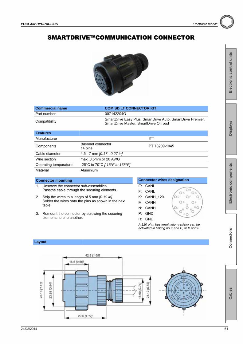
SMARTDRIVE™COMMUNICATION CONNECTOR
Commercial name COM SD LT CONNECTOR KIT
Part number 007142204Q
Compatibility SmartDrive Easy Plus, SmartDrive Auto, SmartDrive Premier, SmartDrive Master, SmartDrive Offroad
Features
Manufacturer ITT
ComponantsBayonet connector14 pins PT 78209-1045
Cable diameter 4.5 - 7 mm [0.17 - 0.27 in]
Wire section max. 0.5mm or 20 AWG
Operating temperature -25°C to 70°C [-13°F to 158°F]
Material Aluminium
Connector mounting Connector wires designation
1. Unscrew the connector sub-assemblies. Passthe cable through the securing elements.
E: CANL
F: CANL
2. Strip the wires to a length of 5 mm [0.19 in]. Solder the wires onto the pins as shown in the next table.
K: CANH_120
M: CANH
N: CANH
3. Remount the connector by screwing the securing elements to one another.
P: GND
R: GND
A 120 ohm bus termination resistor can be activated in linking up K and E, or K and F.
Layout

62 21/02/2014
Electronic mobile POCLAIN HYDRAULICS
SMARTDRIVE™ MALE COMMUNICATION CONNECTOR
Commercial name KIT CONNECTEUR MALE COM SD
Part number A50515H
Compatibility SmartDrive™ Easy Plus, SmartDrive™ Auto
Features
Manufacturer Amphénol
Components
Receptacle PT02A12-14P023
Closing cap BECN1207
Seal JE12
Wire range 0,38 to 0,93 mm2
Insulation diameter 1,2 to 2,4 mm
Operating temperature -55°C to +125°C [-67°F to 257°F]
Ingress Protection IP68
Material Aluminium wit h plated nickel
Connector mounting
Strip the wires to a length of 5 mm [0.19 in]. Solder the wires onto the pins as shown in the table below.
N° pin SD Easy Plus connector Function N° pin male communication connector
7 5V RS 232 A
12 CAN L E, F
26 RX RS 232* H
14 CAN H 120 K
27 TX RS 232* L
13 CAN H M, N
42 Ground P, R
Risk of damage to the serial port of the ECU.
When connecting an external equipment working with the RS232 link, be sure to connect as following:
- RX RS 232 (Easy) TX RS232 (Various equipment)- TX RS 232 (Easy) RX RS232 (Various equipment)

21/02/2014 63
POCLAIN HYDRAULICS Electronic mobile
Ele
ctr
on
ic c
on
tro
l u
nit
sE
lect
ron
ic c
om
po
nen
tsC
on
nec
tors
Cab
les
Dis
pla
ys
Layout
26,2
[1.0
3]
26,2[1.03]
20,62[0.81]
20,6
2[0
.81]
Ø 3,2
[dia. 0.12]
10,95[0.43]
12,5[0.49]
19,0
5[0
.75]
26,2[1.03]
26,2
[1.0
3]
Ø 19,05[dia. 0.75]
105 ±5[4.13 ± 0.2]
25,4
max
.[m
ax. 0
.99]
19 max.[max. 0.75]
Ø 3,3
[dia. 0.13]
Ø 3,6[dia. 0.14]
Seal
Closing cap
Receptacle
Nylon cord
64 21/02/2014
Electronic mobile POCLAIN HYDRAULICS
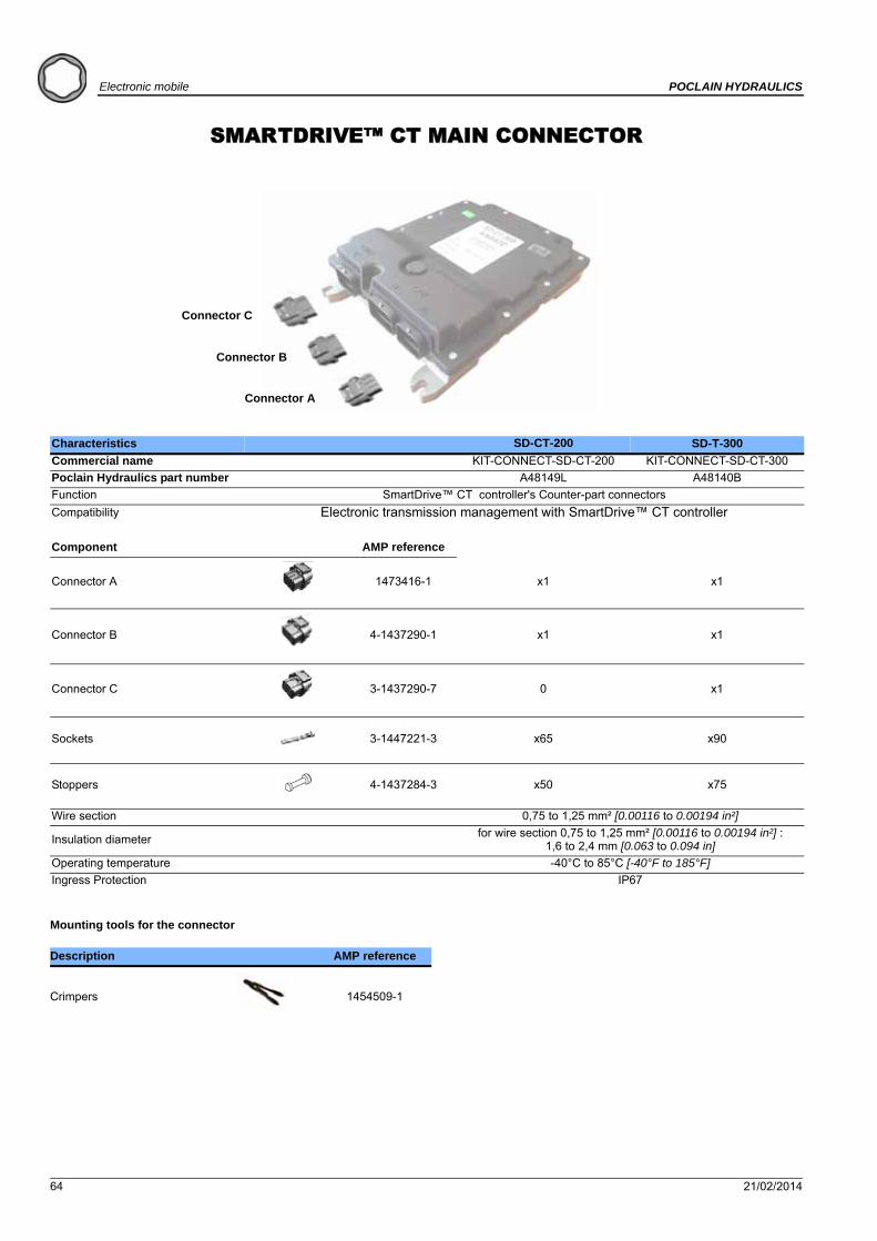
SMARTDRIVE™ CT MAIN CONNECTOR
Mounting tools for the connector
Characteristics SD-CT-200 SD-T-300
Commercial name KIT-CONNECT-SD-CT-200 KIT-CONNECT-SD-CT-300
Poclain Hydraulics part number A48149L A48140B
Function SmartDrive™ CT controller's Counter-part connectors
Compatibility Electronic transmission management with SmartDrive™ CT controller
Component AMP reference
Connector A 1473416-1 x1 x1
Connector B 4-1437290-1 x1 x1
Connector C 3-1437290-7 0 x1
Sockets 3-1447221-3 x65 x90
Stoppers 4-1437284-3 x50 x75
Wire section 0,75 to 1,25 mm² [0.00116 to 0.00194 in²]
Insulation diameterfor wire section 0,75 to 1,25 mm² [0.00116 to 0.00194 in²] :
1,6 to 2,4 mm [0.063 to 0.094 in]
Operating temperature -40°C to 85°C [-40°F to 185°F]
Ingress Protection IP67
Description AMP reference
Crimpers 1454509-1
Connector C
Connector B
Connector A

21/02/2014 65
POCLAIN HYDRAULICS Electronic mobile
Ele
ctr
on
ic c
on
tro
l u
nit
sE
lect
ron
ic c
om
po
nen
tsC
on
nec
tors
Cab
les
Dis
pla
ys
Overall dimensions
Connector A: 1473416-1 Connector B: 4-1437290-1
Connector C: 3-1437290-7 Socket:3-1447221-3
Stopper: 4-1437284-3
34,5
5[1
.36]
18,1
[0.7
1]
32,2[1.27]
34,5
5[1
.36]
18,1
[0.7
1]
38,2[1.50]
34,5
5[1
.36]
18,3
[0.7
2]
32,2[1.27]
33,2 [1.31]
9,7
[0.3
8]
Ø 3[dia. 0.12]
66 21/02/2014
Electronic mobile POCLAIN HYDRAULICS
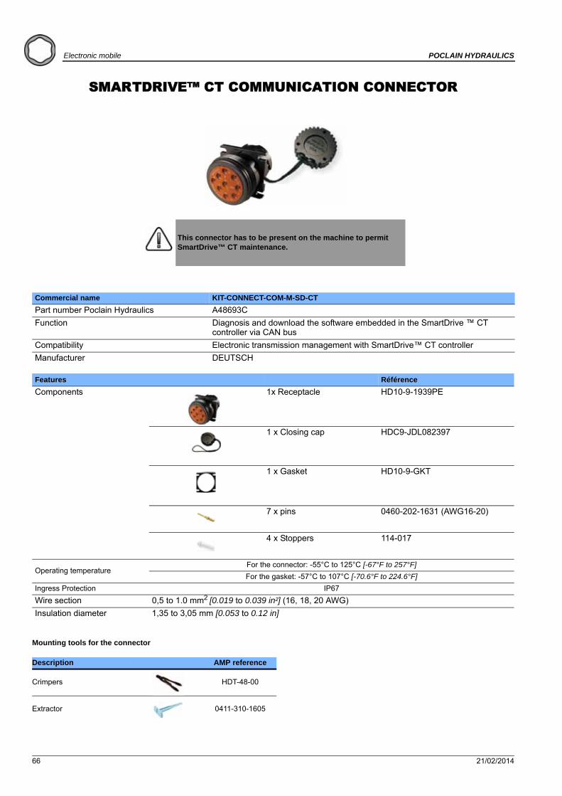
SMARTDRIVE™ CT COMMUNICATION CONNECTOR
Mounting tools for the connector
This connector has to be present on the machine to permit SmartDrive™ CT maintenance.
Commercial name KIT-CONNECT-COM-M-SD-CT
Part number Poclain Hydraulics A48693C
Function Diagnosis and download the software embedded in the SmartDrive ™ CT controller via CAN bus
Compatibility Electronic transmission management with SmartDrive™ CT controller
Manufacturer DEUTSCH
Features Référence
Components 1x Receptacle HD10-9-1939PE
1 x Closing cap HDC9-JDL082397
1 x Gasket HD10-9-GKT
7 x pins 0460-202-1631 (AWG16-20)
4 x Stoppers 114-017
Operating temperatureFor the connector: -55°C to 125°C [-67°F to 257°F]
For the gasket: -57°C to 107°C [-70.6°F to 224.6°F]
Ingress Protection IP67
Wire section 0,5 to 1.0 mm2 [0.019 to 0.039 in²] (16, 18, 20 AWG)
Insulation diameter 1,35 to 3,05 mm [0.053 to 0.12 in]
Description AMP reference
Crimpers HDT-48-00
Extractor 0411-310-1605
21/02/2014 67
POCLAIN HYDRAULICS Electronic mobile
Ele
ctr
on
ic c
on
tro
l u
nit
sE
lect
ron
ic c
om
po
nen
tsC
on
nec
tors
Cab
les
Dis
pla
ys
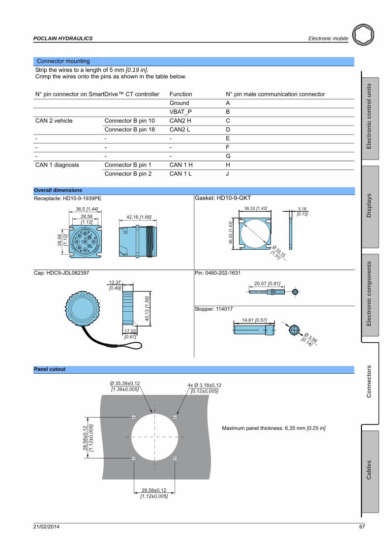
Connector mounting
Strip the wires to a length of 5 mm [0.19 in]. Crimp the wires onto the pins as shown in the table below.
N° pin connector on SmartDrive™ CT controller Function N° pin male communication connector
Ground A
VBAT_P B
CAN 2 vehicle Connector B pin 10 CAN2 H C
Connector B pin 18 CAN2 L D
- - - E
- - - F
- - - G
CAN 1 diagnosis Connector B pin 1 CAN 1 H H
Connector B pin 2 CAN 1 L J
Overall dimensions
Receptacle: HD10-9-1939PE Gasket: HD10-9-GKT
Cap: HDC9-JDL082397 Pin: 0460-202-1631
Stopper: 114017
Panel cutout
42,16 [1.66]28,58[1.12]
28,5
8[1
.12]
36,5 [1.44] 36,32 [1.43] 3,18[0.13]
36,3
2 [1
.43]
Ø 33,15[1.31]
40,1
3 [1
.58]
17,02[0.67]
12,37[0.49]
20,57 [0.81]
14,61 [0.57]
Ø 3,56[0.14]
28,58±0,12[1.12±0,005]
28,5
8±0,
12[1
.12±
0,00
5]
Ø 35,38±0,12[1.39±0,005]
4x Ø 3,18±0,12[0.12±0,005]
Maximum panel thickness: 6,35 mm [0.25 in]

68 21/02/2014
Electronic mobile POCLAIN HYDRAULICS
CONNECTOR KIT 120ΩKIT
Mounting tools for the connector
Commercial name KIT-PLUG-120-DTM-2S
Part number A52539H
Function 120Ω termination resistor for CAN bus
Compatibility Electronic transmission management with SmartDrive™ CT controller and Display 4.3C.
Features Référence
Components 1 x receptacle DTM04-2P-P007
2 x connectors DMT06-2S
1 x wedgelock WM-2S
1 x wedgelock WM-2SB
1 x connector with integrated resistance
DMT06-2S-EP10
7 x sockets 0462-201-2031
Operating temperature -55°C to 125°C [-67°F to 257°F]
Wire section 0,2 to 0,5 mm2 [0.008 to 0.019 in²]
Insulation diameter 1,35 to 3,05 mm [0.053 to 0.12 in]
Pin material Gold plated
Contact size 20
Description AMP reference
Crimpers HDT-48-00

21/02/2014 69
POCLAIN HYDRAULICS Electronic mobile
Ele
ctr
on
ic c
on
tro
l u
nit
sE
lect
ron
ic c
om
po
nen
tsC
on
nec
tors
Cab
les
Dis
pla
ys
Connector mounting
Strip the wires to a length of 5 mm [0.19 in]. Crimp the wires onto the sockets as shown in the diagram below.
Dimensions
Receptacle Y: DTM04-2P-P007 Socket: 0462-201-2031
Connector: DTM06-2S Connector with integrated resistance: DTM06-2S-EP10
Orange wedgelock: WM-2S Black wedgelock: WM-2SB
CAN_H
CAN_L
DTM06-2S
WM-2SBReceptacle Y
DTM04-2P-P007
DTM06-2S
WM-2S
DTM06-2S-EP10connector with integrated
resistance
CA
N_H
CA
N_L
ECU
6543 2 1
78
12
9
11
10XX
37,4
[1.4
7]
17,56[0.69]
50,8 [1.99]
Ø 5,08
[dia. 0.20]5,59[0.22] 16,43 [0.65]
Ø 2,56[dia. 0.10]
27,56 [1.08]
12,0
7[0
.47]
12,9
1[0
.51]
14,4
5[0
.57]
28,83 [1.13]
12,9
[0.5
1]
Bouchon 120 Ω
19,02 [0.75]
5,46
[0.2
1]
5,46
[0.2
1]
19,02 [0.75]

70 21/02/2014
Electronic mobile POCLAIN HYDRAULICS
DISPLAY 4.3C MAIN CONNECTOR
Mounting tools for the connector
Characteristics Display 4.3C
Commercial name KIT-CONNECT-DISPLAY-4.3C
Poclain Hydraulics part number A49050Q
Function Display 4.3C´s Counter-part connectors
Compatibility Electronic transmission management with SmartDrive controllers.
Component AMP reference
Connector 3-1437290-7 x1
Sockets 3-1447221-3 x8
Stoppers 4-1437284-3 x22
Wire section 0,75 to 1,25 mm² [0.00116 to 0.00194 in²]
Insulation diameterfor wire section 0,75 to 1,25 mm² [0.00116 to 0.00194 in²]:
1,6 to 2,4 mm [0.063 to 0.094 in]
Operating temperature -40°C to 85°C [-40°F to 185°F]
Ingress Protection IP67
Description AMP reference
Crimpers 1454509-1
Overall dimensions
Connector: 3-1437290-7 Socket:3-1447221-3
Stopper: 4-1437284-3
34,5
5[1
.36]
18,3
[0.7
2]
32,2[1.27]
33,2 [1.31]
9,7
[0.3
8]
Ø 3[dia. 0.12]
21/02/2014 71
POCLAIN HYDRAULICS Electronic mobile
Ele
ctr
on
ic c
on
tro
l u
nit
sE
lect
ron
ic c
om
po
nen
tsC
on
nec
tors
Cab
les
Dis
pla
ys
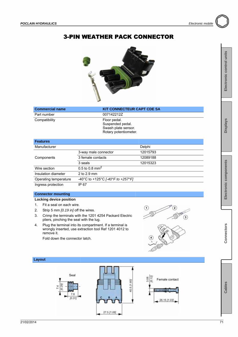
3-PIN WEATHER PACK CONNECTOR
Commercial name KIT CONNECTEUR CAPT CDE SA
Part number 007142212Z
Compatibility Floor pedal.Suspended pedal.Swash plate sensor.Rotary potentiometer.
Features
Manufacturer Delphi
Components
3-way male connector 12015793
3 female contacts 12089188
3 seals 12015323
Wire section 0.5 to 0.8 mm2
Insulation diameter 2 to 2.9 mm
Operating temperature -40°C to +125°C [-40°F to +257°F]
Ingress protection IP 67
Connector mounting
Locking device position
1. Fit a seal on each wire.
2. Strip 5 mm [0.19 in] off the wires.
3. Crimp the terminals with the 1201 4254 Packard Electric pliers, pinching the seal with the lug.
4. Plug the terminal into its compartment. If a terminal is wrongly inserted, use extraction tool Ref 1201 4012 to remove it.
Fold down the connector latch.
Layout
SealFemale contact
72 21/02/2014
Electronic mobile POCLAIN HYDRAULICS
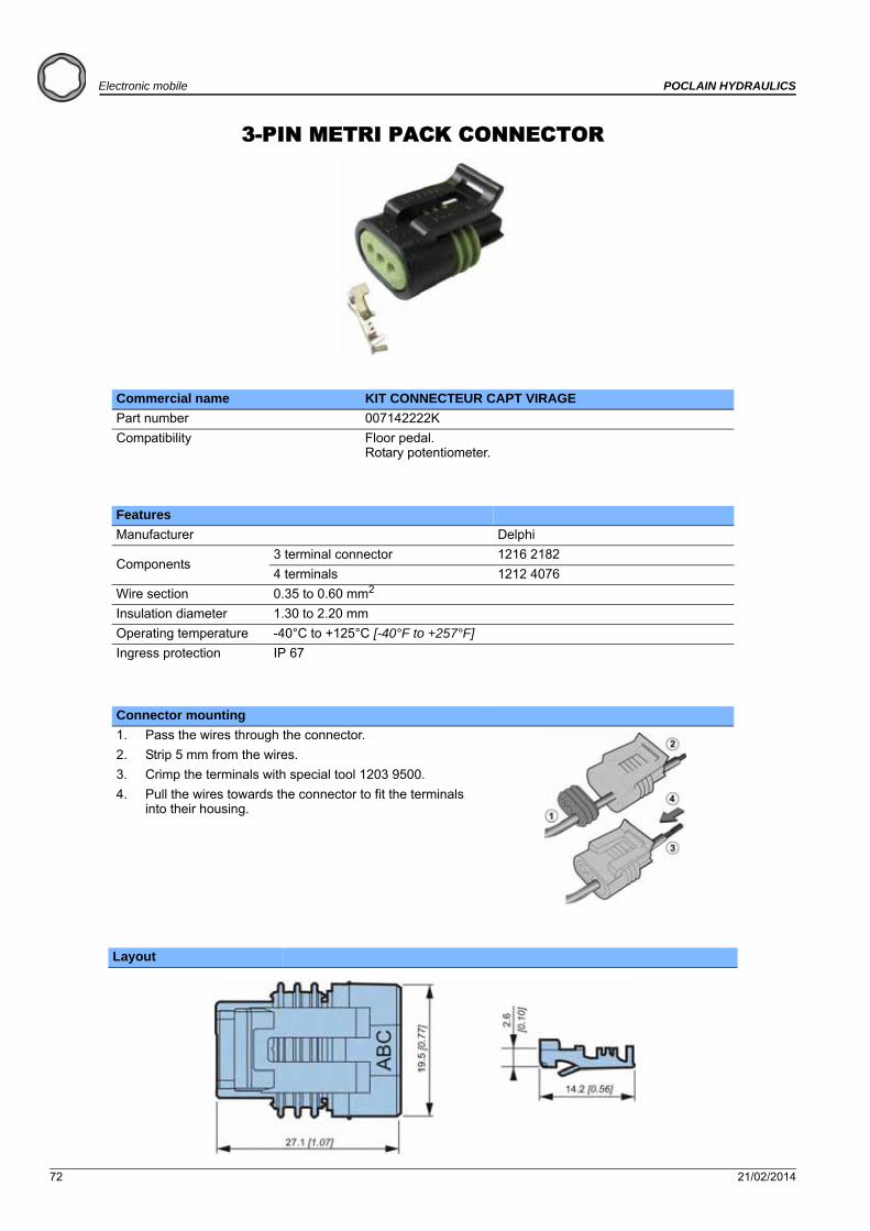
3-PIN METRI PACK CONNECTOR
Commercial name KIT CONNECTEUR CAPT VIRAGE
Part number 007142222K
Compatibility Floor pedal.Rotary potentiometer.
Features
Manufacturer Delphi
Components3 terminal connector 1216 2182
4 terminals 1212 4076
Wire section 0.35 to 0.60 mm2
Insulation diameter 1.30 to 2.20 mm
Operating temperature -40°C to +125°C [-40°F to +257°F]
Ingress protection IP 67
Connector mounting
1. Pass the wires through the connector.
2. Strip 5 mm from the wires.
3. Crimp the terminals with special tool 1203 9500.
4. Pull the wires towards the connector to fit the terminals into their housing.
Layout
21/02/2014 73
POCLAIN HYDRAULICS Electronic mobile
Ele
ctr
on
ic c
on
tro
l u
nit
sE
lect
ron
ic c
om
po
nen
tsC
on
nec
tors
Cab
les
Dis
pla
ys
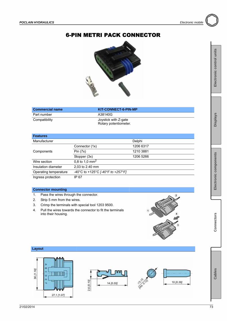
6-PIN METRI PACK CONNECTOR
Commercial name KIT-CONNECT-6-PIN-MP
Part number A38140G
Compatibility Joystick with Z-gateRotary potentiometer.
Features
Manufacturer Delphi
Components
Connector (1x) 1206 6317
Pin (7x) 1210 3881
Stopper (3x) 1206 5266
Wire section 0,8 to 1,0 mm2
Insulation diameter 2,03 to 2.40 mm
Operating temperature -40°C to +125°C [-40°F to +257°F]
Ingress protection IP 67
Connector mounting
1. Pass the wires through the connector.
2. Strip 5 mm from the wires.
3. Crimp the terminals with special tool 1203 9500.
4. Pull the wires towards the connector to fit the terminals into their housing.
Layout

74 21/02/2014
Electronic mobile POCLAIN HYDRAULICS
EN 175301 - 803 STYLE A CONNECTOR
Commercial name KIT CONNECT CDE SA
Part number 007142211X
Compatibility Proportional control electro-valve.Electro-valve solenoid control.
Features
Manufacturer Hirschmann
Standard EN 175301 - 803 style A (DIN43650)
Components 2 connectors GDM 2011 with 2 screws and 2 seals GDM-3-17
Max. currrent 16 A
Max. voltage 250 V (AV)
Wire section max. 1.5 mm2
Cable diameter 6 mm [0.24 in] to 9 mm [0.35 in]
Operating temperature -40°C to +125°C [-40°F to +257°F]
Ingress Protection IP65
Connector mounting
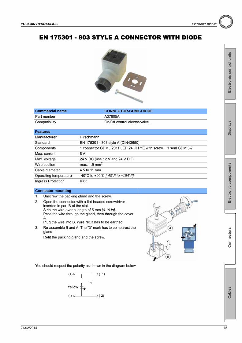
1. Unscrew the packing gland and the screw.
2. Open the connector with a flat-headed screwdriver inserted in part B of the slot.Strip the wire over a length of 5 mm [0.19 in].Pass the wire through the gland, then through the cover A.Plug the wire into B. Wire No.3 has to be earthed.
3. Re-assemble B and A: The "3" mark has to be nearest the gland.
Refit the packing gland and the screw.
Layout
Red sealScrew M3
Cable gland
(PG11)
21/02/2014 75
POCLAIN HYDRAULICS Electronic mobile
Ele
ctr
on
ic c
on
tro
l u
nit
sE
lect
ron
ic c
om
po
nen
tsC
on
nec
tors
Cab
les
Dis
pla
ys
EN 175301 - 803 STYLE A CONNECTOR WITH DIODE
Commercial name CONNECTOR-GDML-DIODE
Part number A37605A
Compatibility On/Off control electro-valve.
Features
Manufacturer Hirschmann
Standard EN 175301 - 803 style A (DIN43650)
Components 1 connector GDML 2011 LED 24 HH YE with screw + 1 seal GDM 3-7
Max. current 8 A
Max. voltage 24 V DC (use 12 V and 24 V DC)
Wire section max. 1.5 mm2
Cable diameter 4.5 to 11 mm
Operating temperature -40°C to +90°C [-40°F to +194°F]
Ingress Protection IP65
Connector mounting
1. Unscrew the packing gland and the screw.
2. Open the connector with a flat-headed screwdriver inserted in part B of the slot.Strip the wire over a length of 5 mm [0.19 in].Pass the wire through the gland, then through the cover A.Plug the wire into B. Wire No.3 has to be earthed.
3. Re-assemble B and A: The "3" mark has to be nearest the gland.
Refit the packing gland and the screw.
You should respect the polarity as shown in the diagram below.
(+)
(-)
(+1)
(-2)
Yellow

76 21/02/2014
Electronic mobile POCLAIN HYDRAULICS
Layout
Brown sealScrew M3
Cable gland
(PG 11)
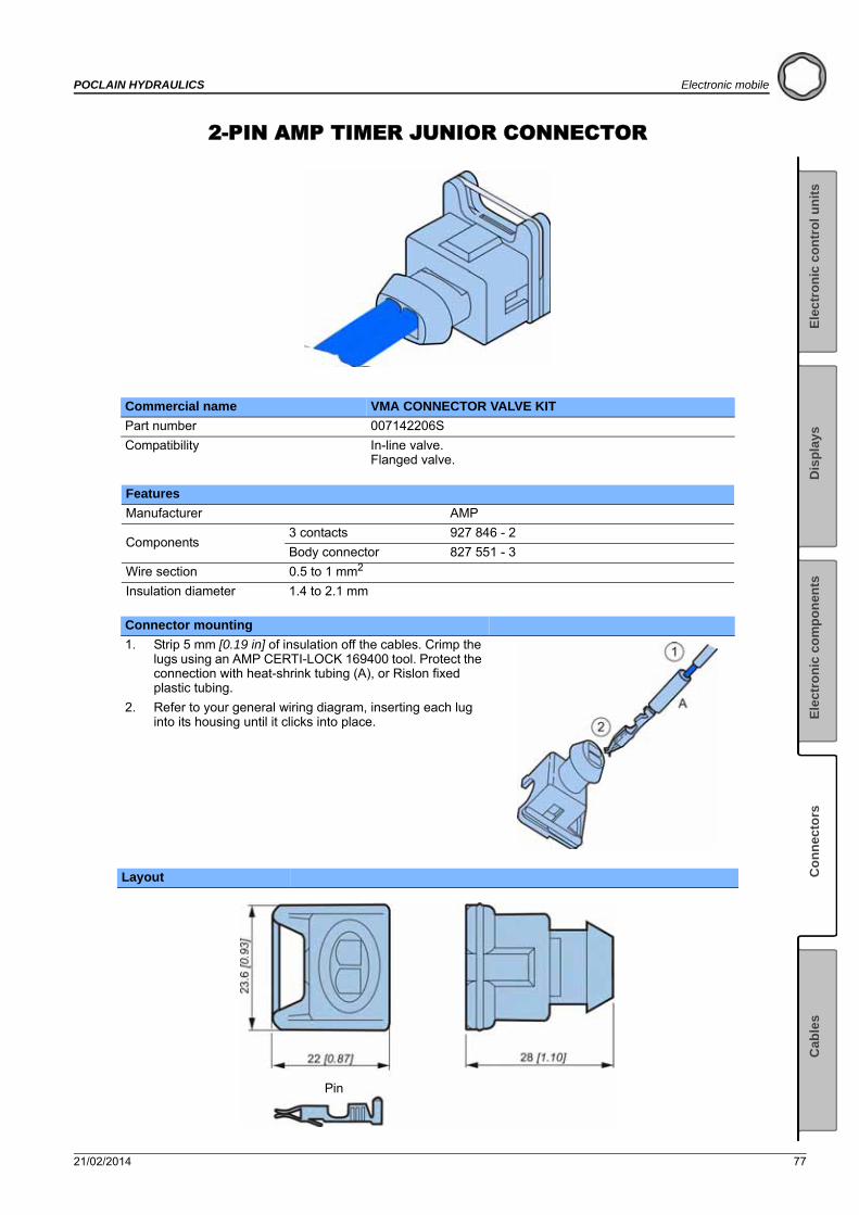
21/02/2014 77
POCLAIN HYDRAULICS Electronic mobile
Ele
ctr
on
ic c
on
tro
l u
nit
sE
lect
ron
ic c
om
po
nen
tsC
on
nec
tors
Cab
les
Dis
pla
ys
2-PIN AMP TIMER JUNIOR CONNECTOR
Commercial name VMA CONNECTOR VALVE KIT
Part number 007142206S
Compatibility In-line valve.Flanged valve.
Features
Manufacturer AMP
Components3 contacts 927 846 - 2
Body connector 827 551 - 3
Wire section 0.5 to 1 mm2
Insulation diameter 1.4 to 2.1 mm
Connector mounting
1. Strip 5 mm [0.19 in] of insulation off the cables. Crimp the lugs using an AMP CERTI-LOCK 169400 tool. Protect the connection with heat-shrink tubing (A), or Rislon fixed plastic tubing.
2. Refer to your general wiring diagram, inserting each lug into its housing until it clicks into place.
Layout
Pin
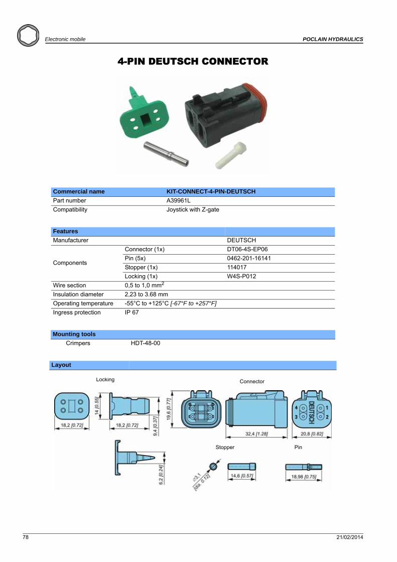
78 21/02/2014
Electronic mobile POCLAIN HYDRAULICS
4-PIN DEUTSCH CONNECTOR
Commercial name KIT-CONNECT-4-PIN-DEUTSCH
Part number A39961L
Compatibility Joystick with Z-gate
Features
Manufacturer DEUTSCH
Components
Connector (1x) DT06-4S-EP06
Pin (5x) 0462-201-16141
Stopper (1x) 114017
Locking (1x) W4S-P012
Wire section 0,5 to 1,0 mm2
Insulation diameter 2,23 to 3.68 mm
Operating temperature -55°C to +125°C [-67°F to +257°F]
Ingress protection IP 67
Mounting tools
Crimpers HDT-48-00
Layout
ConnectorLocking
Stopper Pin
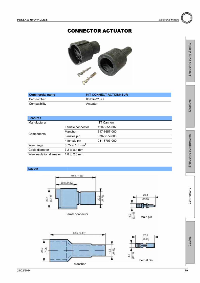
21/02/2014 79
POCLAIN HYDRAULICS Electronic mobile
Ele
ctr
on
ic c
on
tro
l u
nit
sE
lect
ron
ic c
om
po
nen
tsC
on
nec
tors
Cab
les
Dis
pla
ys
CONNECTOR ACTUATOR
Commercial name KIT CONNECT ACTIONNEUR
Part number 007142219G
Compatibility Actuator
Features
Manufacturer ITT Cannon
Components
Female connector 120-8551-007
Manchon 317-8657-000
3 males pin 330-8672-000
4 femals pin 031-8703-000
Wire range 0.75 to 1.5 mm2
Cable diameter 7.2 to 8.4 mm
Wire insulation diameter 1.8 to 2.8 mm
Layout
Femal connector
Manchon
Male pin
Femal pin
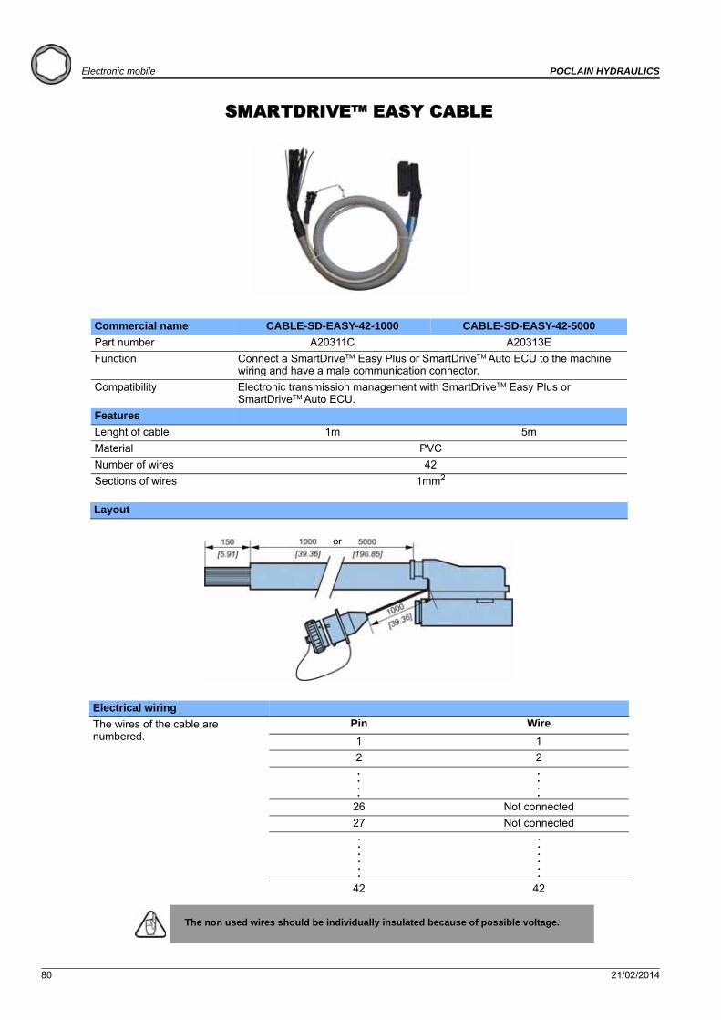
80 21/02/2014
Electronic mobile POCLAIN HYDRAULICS
SMARTDRIVE™ EASY CABLE
Commercial name CABLE-SD-EASY-42-1000 CABLE-SD-EASY-42-5000
Part number A20311C A20313E
Function Connect a SmartDriveTM Easy Plus or SmartDriveTM Auto ECU to the machine wiring and have a male communication connector.
Compatibility Electronic transmission management with SmartDriveTM Easy Plus or SmartDriveTM Auto ECU.
Features
Lenght of cable 1m 5m
Material PVC
Number of wires 42
Sections of wires 1mm2
Layout
Electrical wiring
The wires of the cable are numbered.
Pin Wire
1 1
2 2
26 Not connected
27 Not connected
42 42
The non used wires should be individually insulated because of possible voltage.
or
. . .
. . .
. . .
. . .
. . .
.
. . .
.
Cables
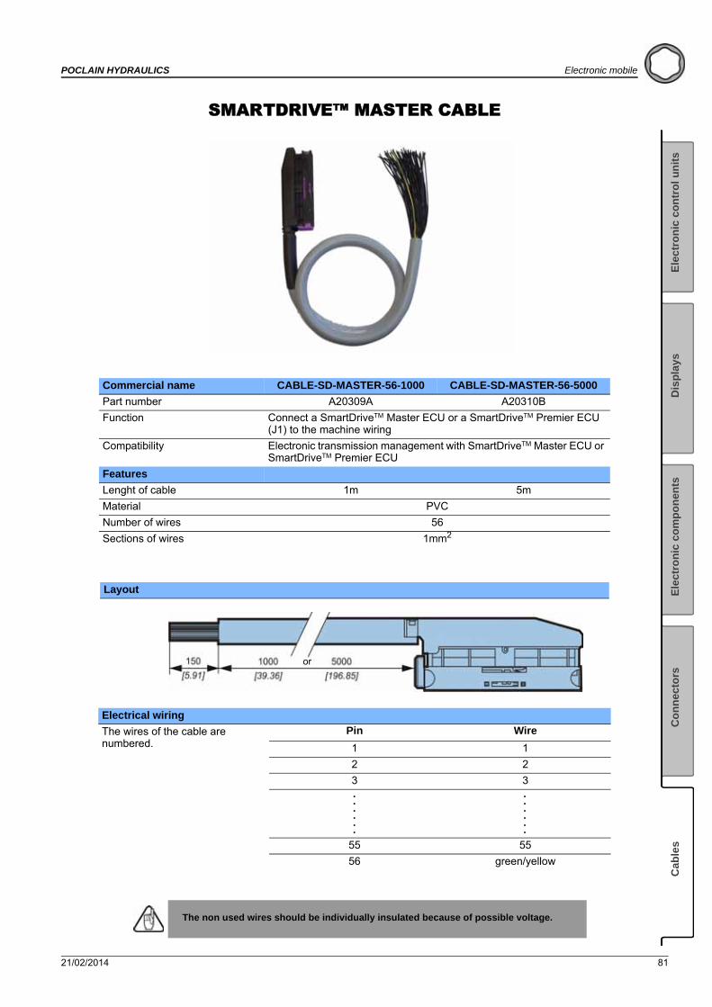
21/02/2014 81
POCLAIN HYDRAULICS Electronic mobile
Ele
ctr
on
ic c
on
tro
l u
nit
sE
lect
ron
ic c
om
po
nen
tsC
on
nec
tors
Cab
les
Dis
pla
ys
SMARTDRIVE™ MASTER CABLE
Commercial name CABLE-SD-MASTER-56-1000 CABLE-SD-MASTER-56-5000
Part number A20309A A20310B
Function Connect a SmartDriveTM Master ECU or a SmartDriveTM Premier ECU (J1) to the machine wiring
Compatibility Electronic transmission management with SmartDriveTM Master ECU or SmartDriveTM Premier ECU
Features
Lenght of cable 1m 5m
Material PVC
Number of wires 56
Sections of wires 1mm2
Layout
Electrical wiring
The wires of the cable are numbered.
Pin Wire
1 1
2 2
3 3
55 55
56 green/yellow
The non used wires should be individually insulated because of possible voltage.
or
. . .
. . .
. . .
. . .
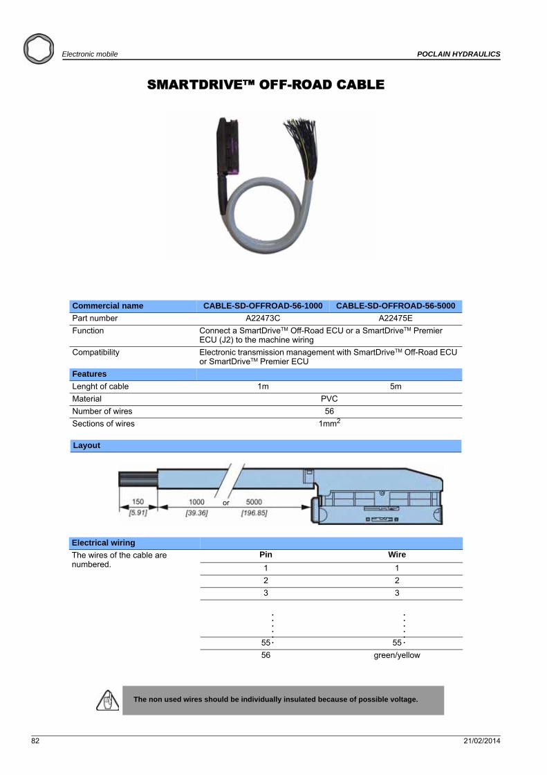
82 21/02/2014
Electronic mobile POCLAIN HYDRAULICS
SMARTDRIVE™ OFF-ROAD CABLE
Commercial name CABLE-SD-OFFROAD-56-1000 CABLE-SD-OFFROAD-56-5000
Part number A22473C A22475E
Function Connect a SmartDriveTM Off-Road ECU or a SmartDriveTM Premier ECU (J2) to the machine wiring
Compatibility Electronic transmission management with SmartDriveTM Off-Road ECU or SmartDriveTM Premier ECU
Features
Lenght of cable 1m 5m
Material PVC
Number of wires 56
Sections of wires 1mm2
Layout
Electrical wiring
The wires of the cable are numbered.
Pin Wire
1 1
2 2
3 3
55 55
56 green/yellow
The non used wires should be individually insulated because of possible voltage.
or
. . .
. . .
. . .
. . .
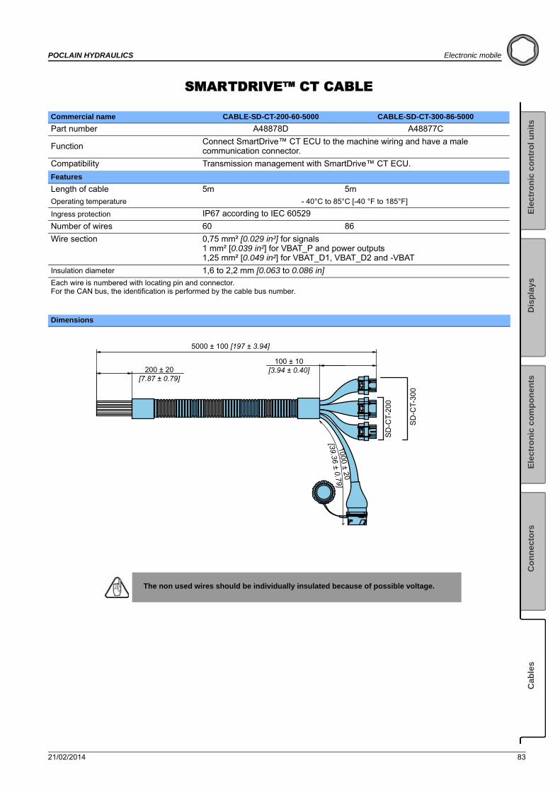
21/02/2014 83
POCLAIN HYDRAULICS Electronic mobile
Ele
ctr
on
ic c
on
tro
l u
nit
sE
lect
ron
ic c
om
po
nen
tsC
on
nec
tors
Cab
les
Dis
pla
ys
SMARTDRIVE™ CT CABLE
Commercial name CABLE-SD-CT-200-60-5000 CABLE-SD-CT-300-86-5000
Part number A48878D A48877C
Function Connect SmartDrive™ CT ECU to the machine wiring and have a male communication connector.
Compatibility Transmission management with SmartDrive™ CT ECU.
Features
Length of cable 5m 5m
Operating temperature - 40°C to 85°C [-40 °F to 185°F]
Ingress protection IP67 according to IEC 60529
Number of wires 60 86
Wire section 0,75 mm² [0.029 in²] for signals1 mm² [0.039 in²] for VBAT_P and power outputs1,25 mm² [0.049 in²] for VBAT_D1, VBAT_D2 and -VBAT
Insulation diameter 1,6 to 2,2 mm [0.063 to 0.086 in]
Each wire is numbered with locating pin and connector.For the CAN bus, the identification is performed by the cable bus number.
Dimensions
The non used wires should be individually insulated because of possible voltage.
200 ± 20[7.87 ± 0.79]
5000 ± 100 [197 ± 3.94]
100 ± 10[3.94 ± 0.40]
1000 ± 20
[39.36 ± 0.79]
SD
-CT-
200
SD
-CT-
300

84 21/02/2014
Electronic mobile POCLAIN HYDRAULICS
SMARTDRIVE™ EASY ADAPTATION CABLEFOR SMARTDRIVE TEST BOX
Commercial name CABLE-EASY-SD-TEST-BOX CABLE-SD-EASY-TEST-BOX
Part number A05786P A05785N
Function Connect a test box to machine wiring which had his transmission controlled by a SmartDriveTM Easy Plus or SmartDriveTM Auto ECU.
Compatibility Electronic transmission management with SmartDriveTM Easy or SmartDriveTM Auto ECU.
Features
Lenght of cable 350 mm

21/02/2014 85
POCLAIN HYDRAULICS Electronic mobile
Ele
ctr
on
ic c
on
tro
l u
nit
sE
lect
ron
ic c
om
po
nen
tsC
on
nec
tors
Cab
les
Dis
pla
ys
SMARTDRIVE™ COMMUNICATION CABLE
Commercial name COM-CABLE-SD-1000 COM-CABLE-SD-5000
Part number A20360F A20361G
Function Connect a SmartDriveTM ECU communication elements to the machine wiring
CompatibilityElectronic transmission management with SmartDrive Easy Plus, SmartDrive Auto, SmartDrive Premier, SmartDrive Master, Smart Drive Offroad.
Features
Lenght of cable 1m 5m
Material PVC
Number of wires 14
Sections of wires 0.22mm2
Layout
Electrical wiring
Pin Wire
A White
B Brown
C Green
D Yellow
E Gray
F Pink
H Blue
J Red
K Black
L Violet
M Gray/Pink
N Red/Blue
P White/Green
R Brown/Green
The non used wires should be individually insulated because of possible voltage.
or

86 21/02/2014
Electronic mobile POCLAIN HYDRAULICS
PRESSURE SENSORS CABLE
Commercial name CABLE-PRESSURE-SENSOR-3M
Part number 003141105U
Features
Lenght of cable 3 m
Material PVC
Number of wires 3
Sections of wires 0.5 mm2
Layout
Electrical wiring
Pin Wire
A Green
B Brown
C White
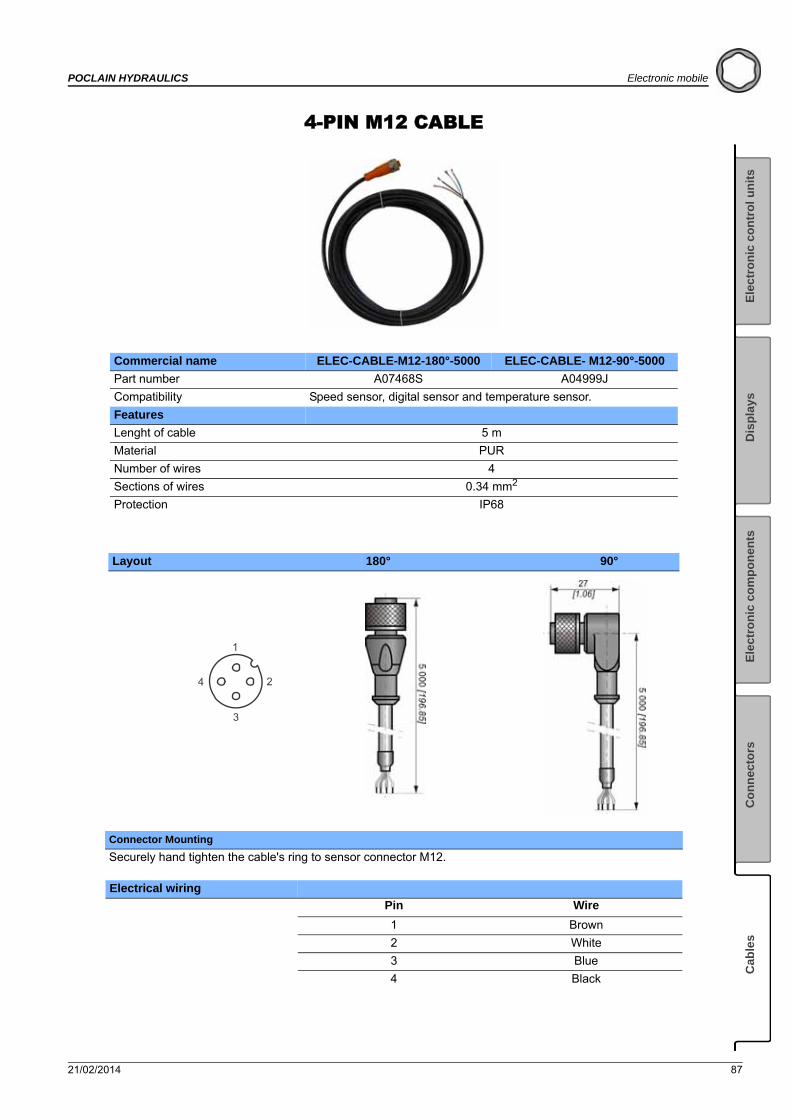
21/02/2014 87
POCLAIN HYDRAULICS Electronic mobile
Ele
ctr
on
ic c
on
tro
l u
nit
sE
lect
ron
ic c
om
po
nen
tsC
on
nec
tors
Cab
les
Dis
pla
ys
4-PIN M12 CABLE
Commercial name ELEC-CABLE-M12-180°-5000 ELEC-CABLE- M12-90°-5000
Part number A07468S A04999J
Compatibility Speed sensor, digital sensor and temperature sensor.
Features
Lenght of cable 5 m
Material PUR
Number of wires 4
Sections of wires 0.34 mm2
Protection IP68
Layout 180° 90°
Connector Mounting
Securely hand tighten the cable's ring to sensor connector M12.
Electrical wiring
Pin Wire
1 Brown
2 White
3 Blue
4 Black
1
2
3
4

88 21/02/2014
Electronic mobile POCLAIN HYDRAULICS
5-PIN M12 CABLE
Commercial name CABLE-M12-180°-2000-5PT
Part number A19974L
Compatibility Display 1.5
Features
Lenght of cable 2 m
Material PUR
Number of wires 5
Sections of wires 0.34 mm2
Protection IP68
Layout
Connector Mounting
Securely hand tighten the cable's ring to sensor connector M12.
Electrical wiring
Pin Wire
1 Brown
2 White
3 Blue
4 Black
5 Grey or Green-yellow
45 [1.77] 2000 ± 50 [78.74 ± 1.97]
M12
x 1
18
[0.7
1]
1
2
3
4
5

21/02/2014 89
POCLAIN HYDRAULICS Electronic mobile
Ele
ctr
on
ic c
on
tro
l u
nit
sE
lect
ron
ic c
om
po
nen
tsC
on
nec
tors
Cab
les
Dis
pla
ys
5-PIN M12 120 OHM CABLE
Commercial name CABLE-COM-M12-CAN-120
Part number A25657N
Function 120 ohm termination resistor for CAN bus
Compatibility Display 1.5
Features
Lenght of cable 0,3 m
Material PUR
Number of wires 5
Sections of wires 0.34 mm2
Protection IP67
Layout
Connector Mounting
Securely hand tighten the cable's ring to sensor connector M12.
R = 120 Ohm ± 5 %
300 ± 10 [11.81 ± 0.39]
1
2
3
4
5
1
2
3
4
5
1
2
3
4
51
2
3
4
5
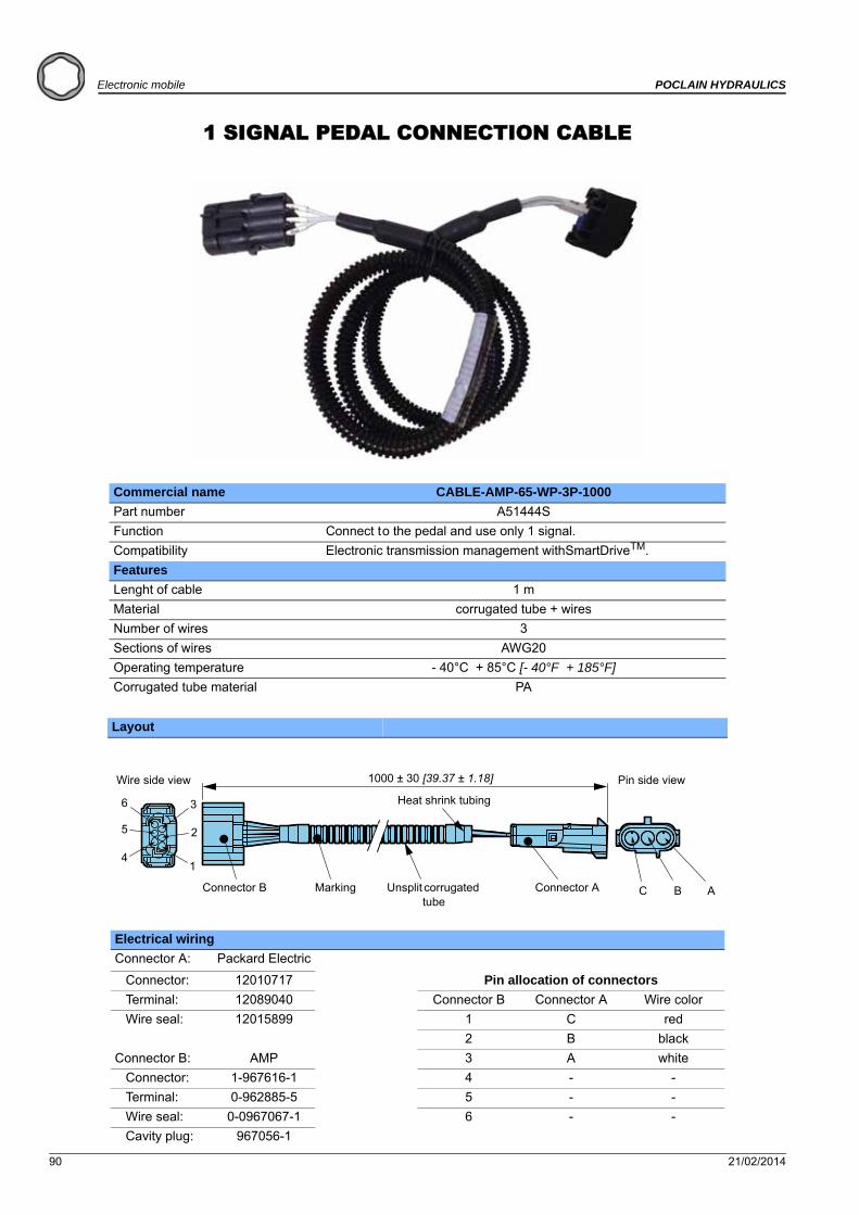
90 21/02/2014
Electronic mobile POCLAIN HYDRAULICS
1 SIGNAL PEDAL CONNECTION CABLE
Commercial name CABLE-AMP-65-WP-3P-1000
Part number A51444S
Function Connect to the pedal and use only 1 signal.
Compatibility Electronic transmission management withSmartDriveTM.
Features
Lenght of cable 1 m
Material corrugated tube + wires
Number of wires 3
Sections of wires AWG20
Operating temperature - 40°C + 85°C [- 40°F + 185°F]
Corrugated tube material PA
Layout
Electrical wiring
Connector A: Packard Electric
Connector: 12010717 Pin allocation of connectors
Terminal: 12089040 Connector B Connector A Wire color
Wire seal: 12015899 1 C red
2 B black
Connector B: AMP 3 A white
Connector: 1-967616-1 4 - -
Terminal: 0-962885-5 5 - -
Wire seal: 0-0967067-1 6 - -
Cavity plug: 967056-1
1
2
36
5
4
C B A
1000 ± 30 [39.37 ± 1.18]Wire side view Pin side view
Connector B Marking Unsplit corrugated tube
Heat shrink tubing
Connector A
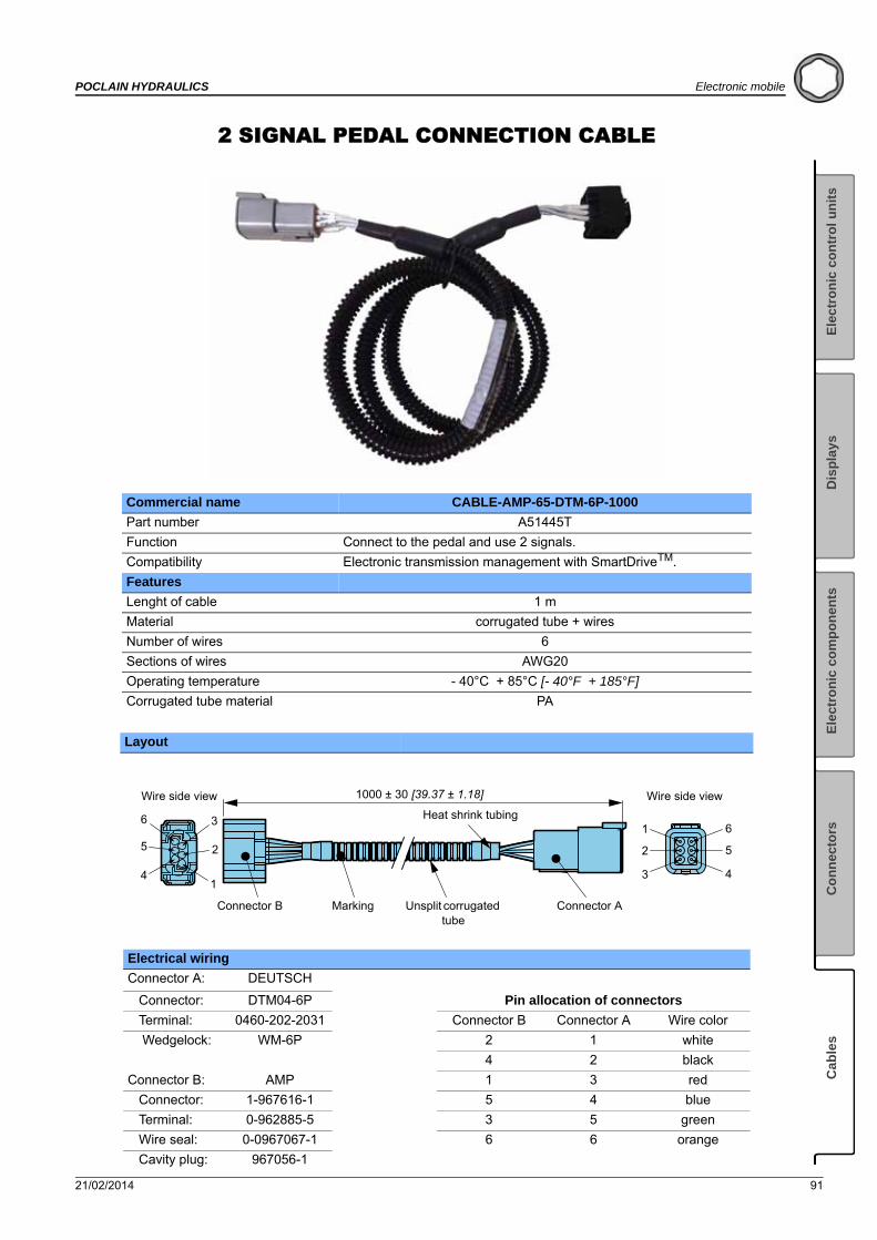
21/02/2014 91
POCLAIN HYDRAULICS Electronic mobile
Ele
ctr
on
ic c
on
tro
l u
nit
sE
lect
ron
ic c
om
po
nen
tsC
on
nec
tors
Cab
les
Dis
pla
ys
2 SIGNAL PEDAL CONNECTION CABLE
Commercial name CABLE-AMP-65-DTM-6P-1000
Part number A51445T
Function Connect to the pedal and use 2 signals.
Compatibility Electronic transmission management with SmartDriveTM.
Features
Lenght of cable 1 m
Material corrugated tube + wires
Number of wires 6
Sections of wires AWG20
Operating temperature - 40°C + 85°C [- 40°F + 185°F]
Corrugated tube material PA
Layout
Electrical wiring
Connector A: DEUTSCH
Connector: DTM04-6P Pin allocation of connectors
Terminal: 0460-202-2031 Connector B Connector A Wire color
Wedgelock: WM-6P 2 1 white
4 2 black
Connector B: AMP 1 3 red
Connector: 1-967616-1 5 4 blue
Terminal: 0-962885-5 3 5 green
Wire seal: 0-0967067-1 6 6 orange
Cavity plug: 967056-1
1
2
36
5
4
6
1000 ± 30 [39.37 ± 1.18]
4
5
1
3
2
Wire side view
Connector B Marking Unsplit corrugated tube
Heat shrink tubing
Connector A
Wire side view

www.poclain-hydraulics.com
Poclain Hydraulics reserves the right to make any modifications it deems necessary to the products described in this document without prior notification.The information contained in this document must be confirmed by Poclain Hydraulics before any order is submitted.Illustrations are not binding.The Poclain Hydraulics brand is the property of Poclain Hydraulics S.A.
A01888C
A01889D
21/02/14