Embed Size (px)
Citation preview

MOBILE GANTRY TUTORIAL
An Introduction to DriveWorksXpress
© DriveWorks Ltd All Rights Reserved 2015
www.driveworksxpress.com
2
CONTENTS INTRODUCTION TO DRIVEWORKSXPRESS .......................................................................................... 3
About the Tutorial ................................................................................................................................................ 3
Getting Started ..................................................................................................................................................... 4
DRIVEWORKSXPRESS NAVIGATION BAR ............................................................................................ 5
REGISTRATION AND BASIC SETUP ...................................................................................................... 6
DriveWorksXpress 2015 Registration .............................................................................................................. 6
BASIC SETUP ....................................................................................................................................... 10
Launching DriveWorksXpress ......................................................................................................................... 10
Create a New Database .................................................................................................................................... 11
CAPTURING MODELS AND DIMENSIONS .......................................................................................... 12
Capturing SOLIDWORKS Models .................................................................................................................... 12
CAPTURING DIMENSIONS AND FEATURES ....................................................................................... 15
Capturing The Universal Beam ....................................................................................................................... 16
Capturing the Leg .............................................................................................................................................. 18
CAPTURING CUSTOM PROPERTIES ................................................................................................... 21
CAPTURING DRAWINGS ..................................................................................................................... 22
CAPTURING CONFIGURATIONS ......................................................................................................... 23
CREATING INPUT FORMS ................................................................................................................... 24
Adding Controls.................................................................................................................................................. 24
TEST MODE .......................................................................................................................................... 29
RULES BUILDER .................................................................................................................................. 30
FILE NAME RULES ............................................................................................................................... 32
Build a rule for the Mobile Gantry File Name ................................................................................................ 33
Build a rule for the Universal Beam File Name............................................................................................. 34
Build a rule for the Leg File Name................................................................................................................... 34
CONFIGURATIONS RULES .................................................................................................................. 35
CUSTOM PROPERTY RULES ............................................................................................................... 36
DIMENSION RULES ............................................................................................................................. 37
BUILD RULES FOR FEATURE .............................................................................................................. 39
RUNNING THE PROJECT ..................................................................................................................... 40
© DriveWorks Ltd All Rights Reserved 2015
www.driveworksxpress.com
3
INTRODUCTION TO DRIVEWORKSXPRESS DriveWorksXpress is entry-level Design Automation software included in SOLIDWORKS. It is ideal if the designs and projects you work on are the Same but Different. It is widely used in many industries from trailers to conveyors, furniture to machinery, mechanical seals to pressure vessels, windows & doors.
You’ll find it already installed and waiting for you to use under the SOLIDWORKS Tools menu. It is ideal for everyday repetitive design tasks. Use it to create multiple variations of SOLIDWORKS Parts, Assemblies and Drawings quickly and accurately.
This DriveWorksXpress tutorial is intended to provide a quick introduction to using DriveWorksXpress.
The Tutorial will show how DriveWorksXpress can:
Reduce the cost of custom designs Create SOLIDWORKS assembly, parts and drawings quickly Enhance product quality Eliminate or reduce repetitive tasks
Upon successful completion of this tutorial, you will be able to:
Drive SOLIDWORKS part and assembly geometry with DriveWorksXpress Create a DriveWorksXpress input form and link the input fields to the SOLIDWORKS model Write rules to configure and run your design projects Generate new parts, assemblies and drawings
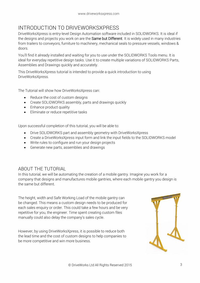
ABOUT THE TUTORIAL In this tutorial, we will be automating the creation of a mobile gantry. Imagine you work for a company that designs and manufactures mobile gantries, where each mobile gantry you design is the same but different.
The height, width and Safe Working Load of the mobile gantry can be changed. This means a custom design needs to be produced for each sales enquiry or order. This could take a few hours and be very repetitive for you, the engineer. Time spent creating custom files manually could also delay the company’s sales cycle.
However, by using DriveWorksXpress, it is possible to reduce both the lead time and the cost of custom designs to help companies to be more competitive and win more business.
© DriveWorks Ltd All Rights Reserved 2015
www.driveworksxpress.com
4
GETTING STARTED To begin this tutorial, you will need to download the SOLIDWORKS project files for the mobile gantry from the DriveWorksXpress website: www.driveworksxpress.com
The SOLIDWORKS files are contained within a zipped file.
Ensure you extract the files from this folder before beginning the training.
By following this DriveWorksXpress tutorial you will soon be automating your own designs in SOLIDWORKS.
© DriveWorks Ltd All Rights Reserved 2015
www.driveworksxpress.com
5
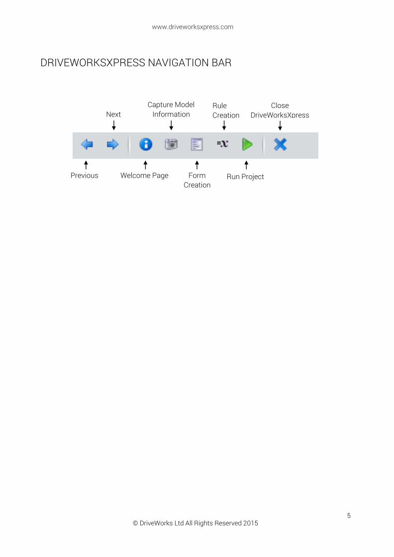
DRIVEWORKSXPRESS NAVIGATION BAR
Run Project
Next
Previous Welcome Page
Capture Model Information
Form Creation
Rule Creation
Close DriveWorksXpress

© DriveWorks Ltd All Rights Reserved 2015
www.driveworksxpress.com
6
REGISTRATION AND BASIC SETUP DriveWorksXpress is included in every seat of SOLIDWORKS. You’ll find DriveWorksXpress by navigating to Tools > Xpress Products > DriveWorksXpress in the SOLIDWORKS tool bar.
The first time you use DriveWorksXpress in SOLIDWORKS 2015, you will need to log into your SOLIDWORKS account and register DriveWorksXpress.
If you are using SOLIDWORKS 2014, you can skip directly to Basic Setup.
DRIVEWORKSXPRESS 2015 REGISTRATION
STEP 1
You’ll need your SOLIDWORKS Serial Number. You can find this by navigating to: Help > About SOLIDWORKS.
© DriveWorks Ltd All Rights Reserved 2015
www.driveworksxpress.com
7
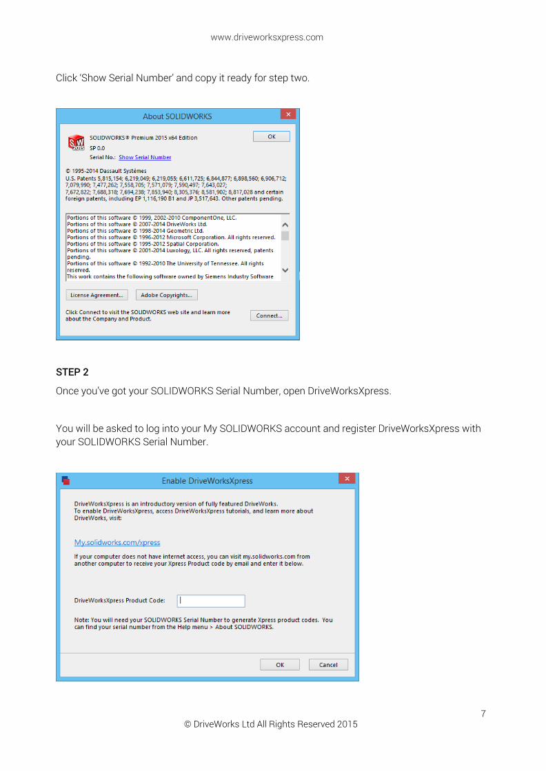
Click ‘Show Serial Number’ and copy it ready for step two.
STEP 2
Once you’ve got your SOLIDWORKS Serial Number, open DriveWorksXpress.
You will be asked to log into your My SOLIDWORKS account and register DriveWorksXpress with your SOLIDWORKS Serial Number.
© DriveWorks Ltd All Rights Reserved 2015
www.driveworksxpress.com
8
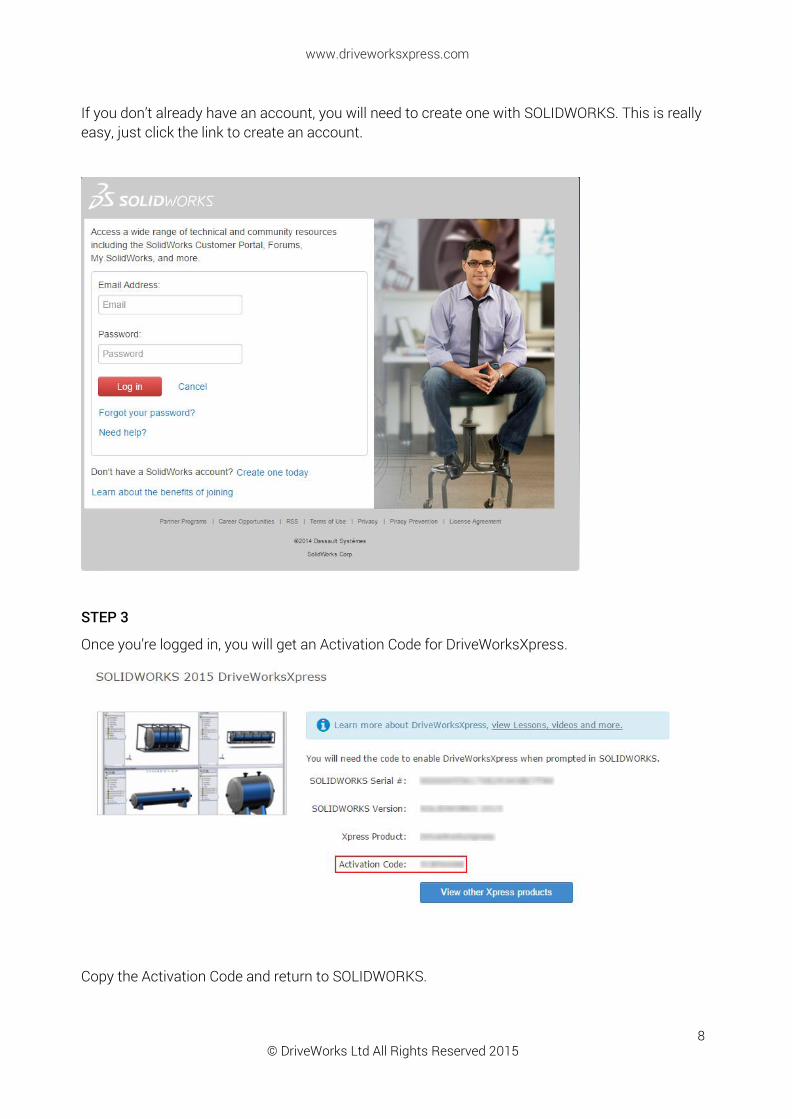
If you don’t already have an account, you will need to create one with SOLIDWORKS. This is really easy, just click the link to create an account.
STEP 3
Once you’re logged in, you will get an Activation Code for DriveWorksXpress.
Copy the Activation Code and return to SOLIDWORKS.

© DriveWorks Ltd All Rights Reserved 2015
www.driveworksxpress.com
9
Paste the code into the activation window and click OK.
DriveWorksXpress will be activated and the task pane will open.
You’re now ready to automate your designs with DriveWorksXpress!
© DriveWorks Ltd All Rights Reserved 2015
www.driveworksxpress.com
10
BASIC SETUP
LAUNCHING DRIVEWORKSXPRESS
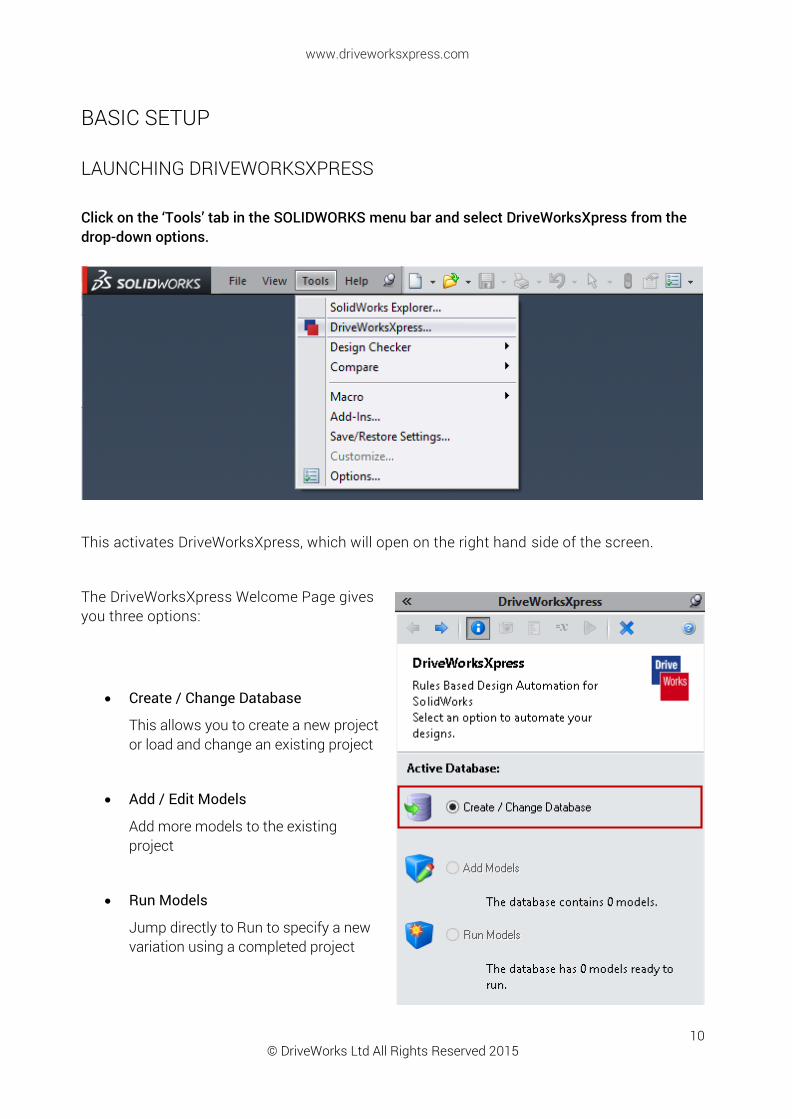
Click on the ‘Tools’ tab in the SOLIDWORKS menu bar and select DriveWorksXpress from the drop-down options.
This activates DriveWorksXpress, which will open on the right hand side of the screen.
The DriveWorksXpress Welcome Page gives you three options:
Create / Change Database
This allows you to create a new project or load and change an existing project
Add / Edit Models
Add more models to the existing project
Run Models
Jump directly to Run to specify a new variation using a completed project

© DriveWorks Ltd All Rights Reserved 2015
www.driveworksxpress.com
11
CREATE A NEW DATABASE
To create a new DriveWorksXpress Database, click the ‘Create/Change Database’ radio button.
Click ‘Next’ in the DriveWorksXpress Task Pane.
You will automatically be asked to open a new database.
Browse to the location where you want to create your new database and name it “Mobile Gantry”.
Click ‘Open’ to save the database and continue.
A new DriveWorksXpress database will be saved in your specified location.
© DriveWorks Ltd All Rights Reserved 2015
www.driveworksxpress.com
12
CAPTURING MODELS AND DIMENSIONS
CAPTURING SOLIDWORKS MODELS
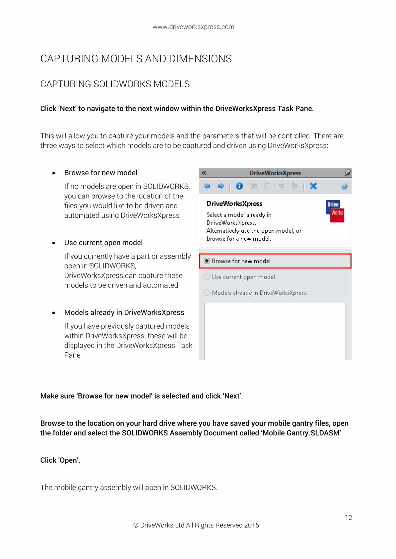
Click ‘Next’ to navigate to the next window within the DriveWorksXpress Task Pane.
This will allow you to capture your models and the parameters that will be controlled. There are three ways to select which models are to be captured and driven using DriveWorksXpress:
Browse for new model
If no models are open in SOLIDWORKS, you can browse to the location of the files you would like to be driven and automated using DriveWorksXpress
Use current open model
If you currently have a part or assembly open in SOLIDWORKS, DriveWorksXpress can capture these models to be driven and automated
Models already in DriveWorksXpress
If you have previously captured models within DriveWorksXpress, these will be displayed in the DriveWorksXpress Task Pane
Make sure ‘Browse for new model’ is selected and click ‘Next’.
Browse to the location on your hard drive where you have saved your mobile gantry files, open the folder and select the SOLIDWORKS Assembly Document called ‘Mobile Gantry.SLDASM’
Click ‘Open’.
The mobile gantry assembly will open in SOLIDWORKS.
© DriveWorks Ltd All Rights Reserved 2015
www.driveworksxpress.com
13
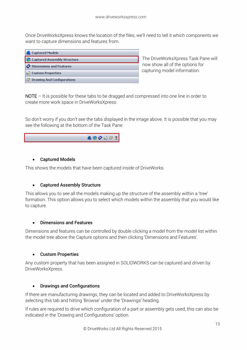
Once DriveWorksXpress knows the location of the files, we’ll need to tell it which components we want to capture dimensions and features from.
The DriveWorksXpress Task Pane will now show all of the options for capturing model information.
NOTE – It is possible for these tabs to be dragged and compressed into one line in order to create more work space in DriveWorksXpress.
So don’t worry if you don’t see the tabs displayed in the image above. It is possible that you may see the following at the bottom of the Task Pane:
Captured Models
This shows the models that have been captured inside of DriveWorks.
Captured Assembly Structure
This allows you to see all the models making up the structure of the assembly within a ‘tree’ formation. This option allows you to select which models within the assembly that you would like to capture.
Dimensions and Features
Dimensions and features can be controlled by double clicking a model from the model list within the model tree above the Capture options and then clicking ‘Dimensions and Features’.
Custom Properties
Any custom property that has been assigned in SOLIDWORKS can be captured and driven by DriveWorksXpress.
Drawings and Configurations
If there are manufacturing drawings, they can be located and added to DriveWorksXpress by selecting this tab and hitting ‘Browse’ under the ‘Drawings’ heading.
If rules are required to drive which configuration of a part or assembly gets used, this can also be indicated in the ‘Drawing and Configurations’ option.
© DriveWorks Ltd All Rights Reserved 2015
www.driveworksxpress.com
14
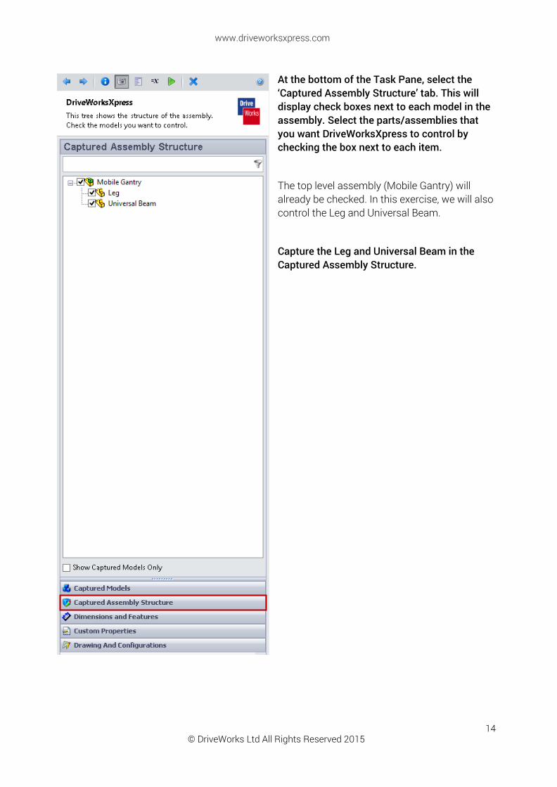
At the bottom of the Task Pane, select the ‘Captured Assembly Structure’ tab. This will display check boxes next to each model in the assembly. Select the parts/assemblies that you want DriveWorksXpress to control by checking the box next to each item.
The top level assembly (Mobile Gantry) will already be checked. In this exercise, we will also control the Leg and Universal Beam.
Capture the Leg and Universal Beam in the Captured Assembly Structure.

© DriveWorks Ltd All Rights Reserved 2015
www.driveworksxpress.com
15
CAPTURING DIMENSIONS AND FEATURES The Dimensions and Features tab allows you to choose which parameters from a model or assembly you would like to capture and drive. You can then assign a descriptive name to the dimension or feature you have selected to make them easier to identify and create rules for.
A parameter is captured by selecting the ‘Captured Models’ tab and then double clicking on the model that the parameter exists in.
This will open the model in SOLIDWORKS allowing you to select the dimensions and features you wish to capture and control.
With the models captured, begin the process of capturing the parameters that you need to control. The following steps will guide you through the process of capturing dimensions and features in DriveWorksXpress.

© DriveWorks Ltd All Rights Reserved 2015
www.driveworksxpress.com
16
CAPTURING THE UNIVERSAL BEAM Double click on the Universal Beam in the ‘Captured Models’ tab and then select the ‘Dimensions and Features’ tab.
We need to capture the Length of the Universal Beam.
In the SOLIDWORKS Feature Manager double click the plane named ‘Right End’. The dimension will appear on the model.
Select the dimension from the model by clicking on the dimension value.
The SOLIDWORKS name of the dimension will appear in the Address field in DriveWorksXpress.
Enter a new DriveWorks Name. This should be something meaningful, for example ‘Beam Length’.
Click ‘Add’.
The captured dimension will be listed under Dimensions and Features in the DriveWorksXpress task pane.
© DriveWorks Ltd All Rights Reserved 2015
www.driveworksxpress.com
17
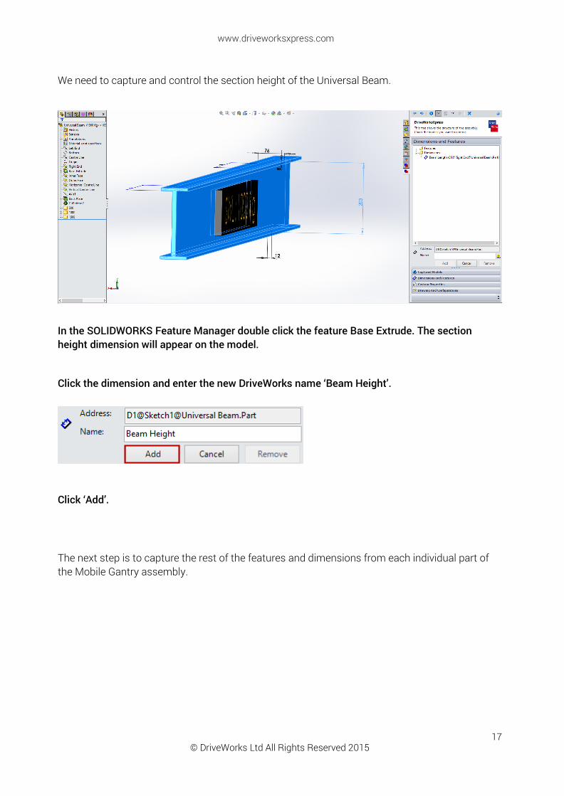
We need to capture and control the section height of the Universal Beam.
In the SOLIDWORKS Feature Manager double click the feature Base Extrude. The section height dimension will appear on the model.
Click the dimension and enter the new DriveWorks name ‘Beam Height’.
Click ‘Add’.
The next step is to capture the rest of the features and dimensions from each individual part of the Mobile Gantry assembly.

© DriveWorks Ltd All Rights Reserved 2015
www.driveworksxpress.com
18
CAPTURING THE LEG Navigate back to the original Mobile Gantry assembly window in SOLIDWORKS by clicking ‘Back’, clicking ‘Captured Models’ or by closing the open model and clicking ‘Next’.
Double click the Leg from the tree view in the ‘Captured Models’ tab.
In the SOLIDWORKS Feature Manager double click the sketch Lower Layout.
The Leg height dimension will appear on the model.
Select the sketch ‘Lower Layout’ and capture the following dimension:
Sketch Name Dimension Value DriveWorks Name Explanation Lower Layout 3000 Leg Height Controls the height of the leg
Enter a new DriveWorks Name, for example ‘Leg Height’.
Click ‘Add’.
© DriveWorks Ltd All Rights Reserved 2015
www.driveworksxpress.com
19
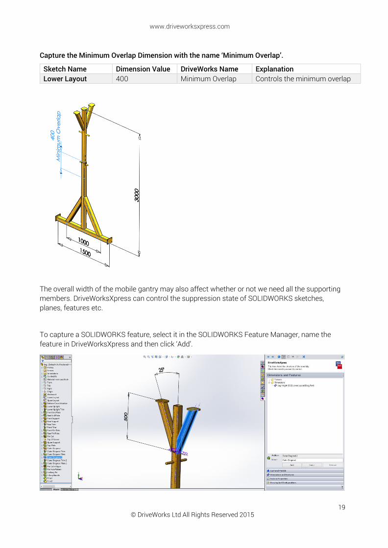
Capture the Minimum Overlap Dimension with the name ‘Minimum Overlap’.
Sketch Name Dimension Value DriveWorks Name Explanation Lower Layout 400 Minimum Overlap Controls the minimum overlap
The overall width of the mobile gantry may also affect whether or not we need all the supporting members. DriveWorksXpress can control the suppression state of SOLIDWORKS sketches, planes, features etc.
To capture a SOLIDWORKS feature, select it in the SOLIDWORKS Feature Manager, name the feature in DriveWorksXpress and then click ‘Add’.
© DriveWorks Ltd All Rights Reserved 2015
www.driveworksxpress.com
20
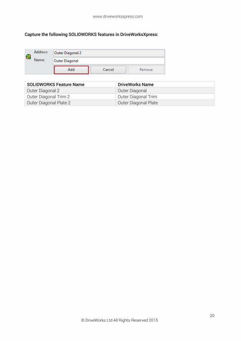
Capture the following SOLIDWORKS features in DriveWorksXpress:
SOLIDWORKS Feature Name DriveWorks Name Outer Diagonal 2 Outer Diagonal Outer Diagonal Trim 2 Outer Diagonal Trim Outer Diagonal Plate 2 Outer Diagonal Plate
© DriveWorks Ltd All Rights Reserved 2015
www.driveworksxpress.com
21
CAPTURING CUSTOM PROPERTIES
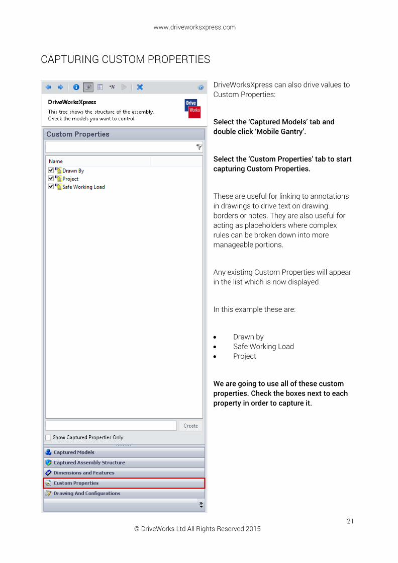
DriveWorksXpress can also drive values to Custom Properties:
Select the ‘Captured Models’ tab and double click ‘Mobile Gantry’.
Select the ‘Custom Properties’ tab to start capturing Custom Properties.
These are useful for linking to annotations in drawings to drive text on drawing borders or notes. They are also useful for acting as placeholders where complex rules can be broken down into more manageable portions.
Any existing Custom Properties will appear in the list which is now displayed.
In this example these are:
Drawn by Safe Working Load Project
We are going to use all of these custom properties. Check the boxes next to each property in order to capture it.
© DriveWorks Ltd All Rights Reserved 2015
www.driveworksxpress.com
22
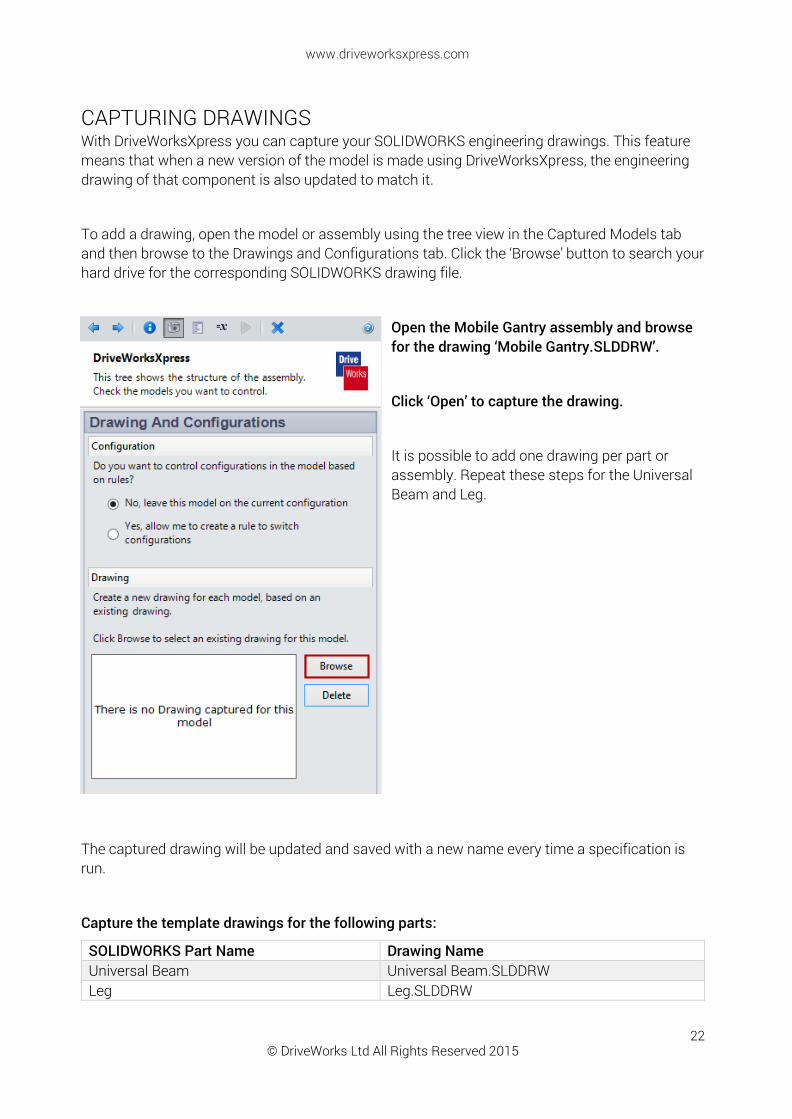
CAPTURING DRAWINGS With DriveWorksXpress you can capture your SOLIDWORKS engineering drawings. This feature means that when a new version of the model is made using DriveWorksXpress, the engineering drawing of that component is also updated to match it.
To add a drawing, open the model or assembly using the tree view in the Captured Models tab and then browse to the Drawings and Configurations tab. Click the ‘Browse’ button to search your hard drive for the corresponding SOLIDWORKS drawing file.
Open the Mobile Gantry assembly and browse for the drawing ‘Mobile Gantry.SLDDRW’.
Click ‘Open’ to capture the drawing.
It is possible to add one drawing per part or assembly. Repeat these steps for the Universal Beam and Leg.
The captured drawing will be updated and saved with a new name every time a specification is run.
Capture the template drawings for the following parts:
SOLIDWORKS Part Name Drawing Name Universal Beam Universal Beam.SLDDRW Leg Leg.SLDDRW
© DriveWorks Ltd All Rights Reserved 2015
www.driveworksxpress.com
23
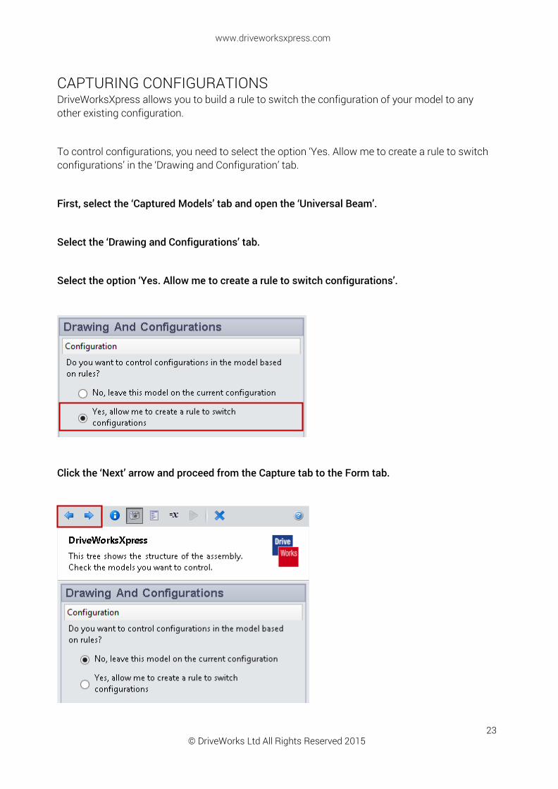
CAPTURING CONFIGURATIONS DriveWorksXpress allows you to build a rule to switch the configuration of your model to any other existing configuration.
To control configurations, you need to select the option ‘Yes. Allow me to create a rule to switch configurations’ in the ‘Drawing and Configuration’ tab.
First, select the ‘Captured Models’ tab and open the ‘Universal Beam’.
Select the ‘Drawing and Configurations’ tab.
Select the option ‘Yes. Allow me to create a rule to switch configurations’.
Click the ‘Next’ arrow and proceed from the Capture tab to the Form tab.

© DriveWorks Ltd All Rights Reserved 2015
www.driveworksxpress.com
24
CREATING INPUT FORMS In DriveWorksXpress you can create an input form for entering the values for your new parts and drawings. This form can be used again and again to specify and generate all the new parts and drawings, based on the rules you set and values you enter.
ADDING CONTROLS To access the Form Designer, click the ‘Next’ arrow at the top of the DriveWorksXpress Task Pane, or select the Form Creation Icon shown below.
Each control requires three things:
Name - You must provide a descriptive name for the form control. This name will be the title the user sees as they fill in your form i.e. Customer Name
Type - Choose from five types of controls (inputs)
Text Box: Input text directly by typing
Numeric Text Box: Input numeric values and specify a minimum and maximum value
Drop Down: Provides a list of options to choose from
Spin Button: Users can select from a range of numeric values. A maximum and a minimum value, as well as the incremented value
Check Box: Places a checkbox on the form
Required - Enforces a value to be entered
© DriveWorks Ltd All Rights Reserved 2015
www.driveworksxpress.com
25
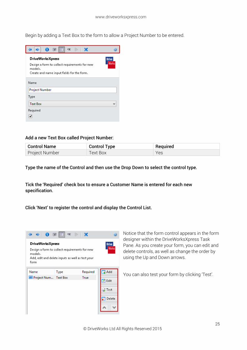
Begin by adding a Text Box to the form to allow a Project Number to be entered.
Add a new Text Box called Project Number:
Control Name Control Type Required Project Number Text Box Yes
Type the name of the Control and then use the Drop Down to select the control type.
Tick the ‘Required’ check box to ensure a Customer Name is entered for each new specification.
Click ‘Next’ to register the control and display the Control List.
Notice that the form control appears in the form designer within the DriveWorksXpress Task Pane. As you create your form, you can edit and delete controls, as well as change the order by using the Up and Down arrows.
You can also test your form by clicking ‘Test’.

© DriveWorks Ltd All Rights Reserved 2015
www.driveworksxpress.com
26
Click ‘Add’ and repeat the steps to add the following controls:
Add a new Text Box called Customer Name:
Control Name Control Type Required Customer Name Text Box Yes
Add a new Drop Down called Drawn By:
Control Name Control Type Required Options Drawn By Drop Down Yes Matt, Rob, Tom, Phil
NOTE: Separate items in the Options field of the Drop Down by using pipe bars (Matt|Rob) or by pressing Ctrl+Enter after each entry to add a new row.
© DriveWorks Ltd All Rights Reserved 2015
www.driveworksxpress.com
27
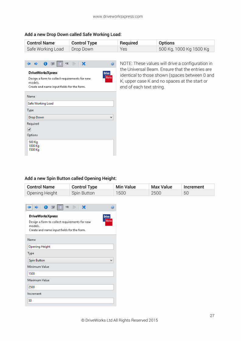
Add a new Drop Down called Safe Working Load:
Control Name Control Type Required Options Safe Working Load Drop Down Yes 500 Kg, 1000 Kg 1500 Kg
NOTE: These values will drive a configuration in the Universal Beam. Ensure that the entries are identical to those shown (spaces between 0 and K, upper case K and no spaces at the start or end of each text string.
Add a new Spin Button called Opening Height:
Control Name Control Type Min Value Max Value Increment Opening Height Spin Button 1500 2500 50
© DriveWorks Ltd All Rights Reserved 2015
www.driveworksxpress.com
28
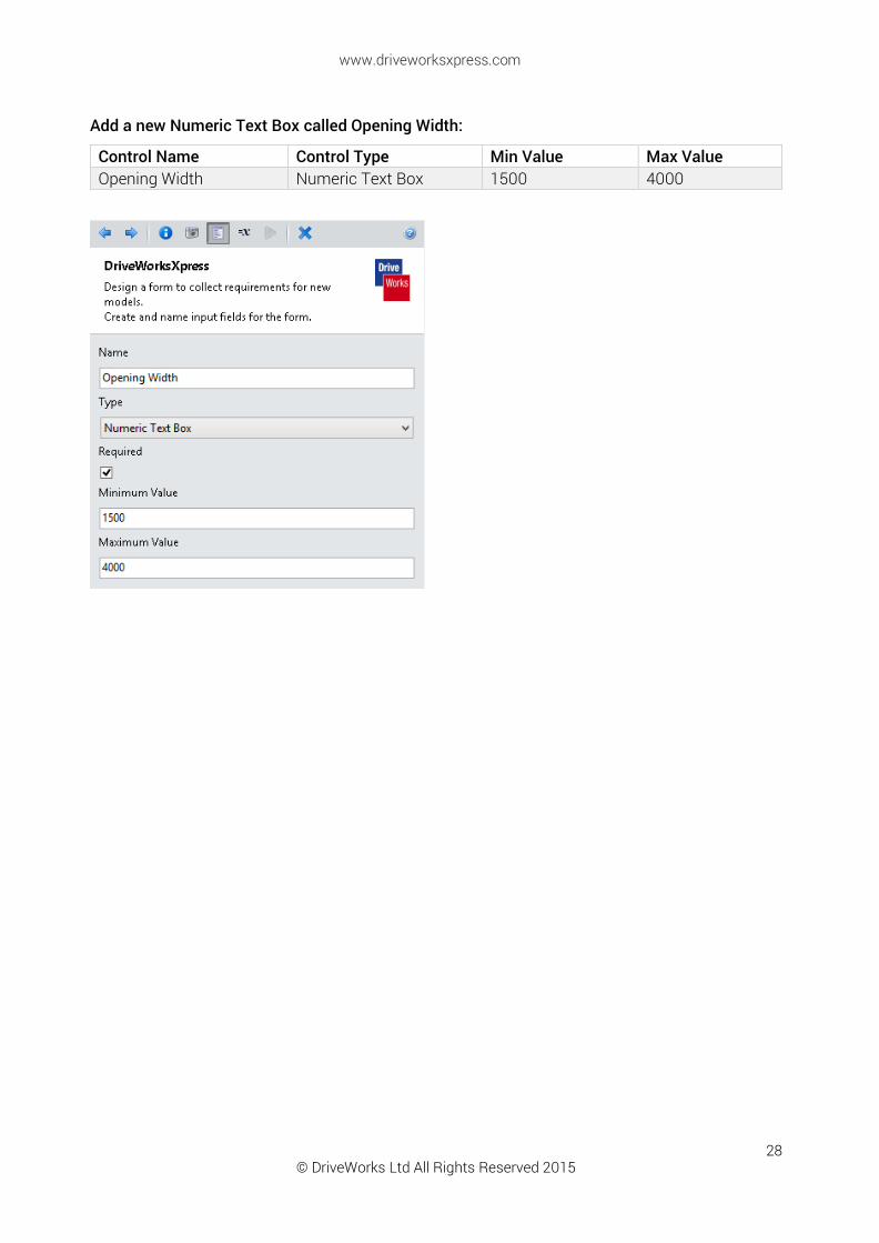
Add a new Numeric Text Box called Opening Width:
Control Name Control Type Min Value Max Value Opening Width Numeric Text Box 1500 4000

© DriveWorks Ltd All Rights Reserved 2015
www.driveworksxpress.com
29
TEST MODE
Click ‘Test’ within the Form Designer to preview the form you have created and test it out for yourself.
You will notice that as you fill out the forms with valid information, the background of the text boxes will change from pink to white and the yellow warning triangles will disappear.
If you hover over a control, information about the control will be shown in a tooltip.
It’s good practice to set default values for controls. Setting default values makes building rules easier because the controls have values.
To set a default value, enter values into the form controls and click ‘Set Defaults’.
© DriveWorks Ltd All Rights Reserved 2015
www.driveworksxpress.com
30
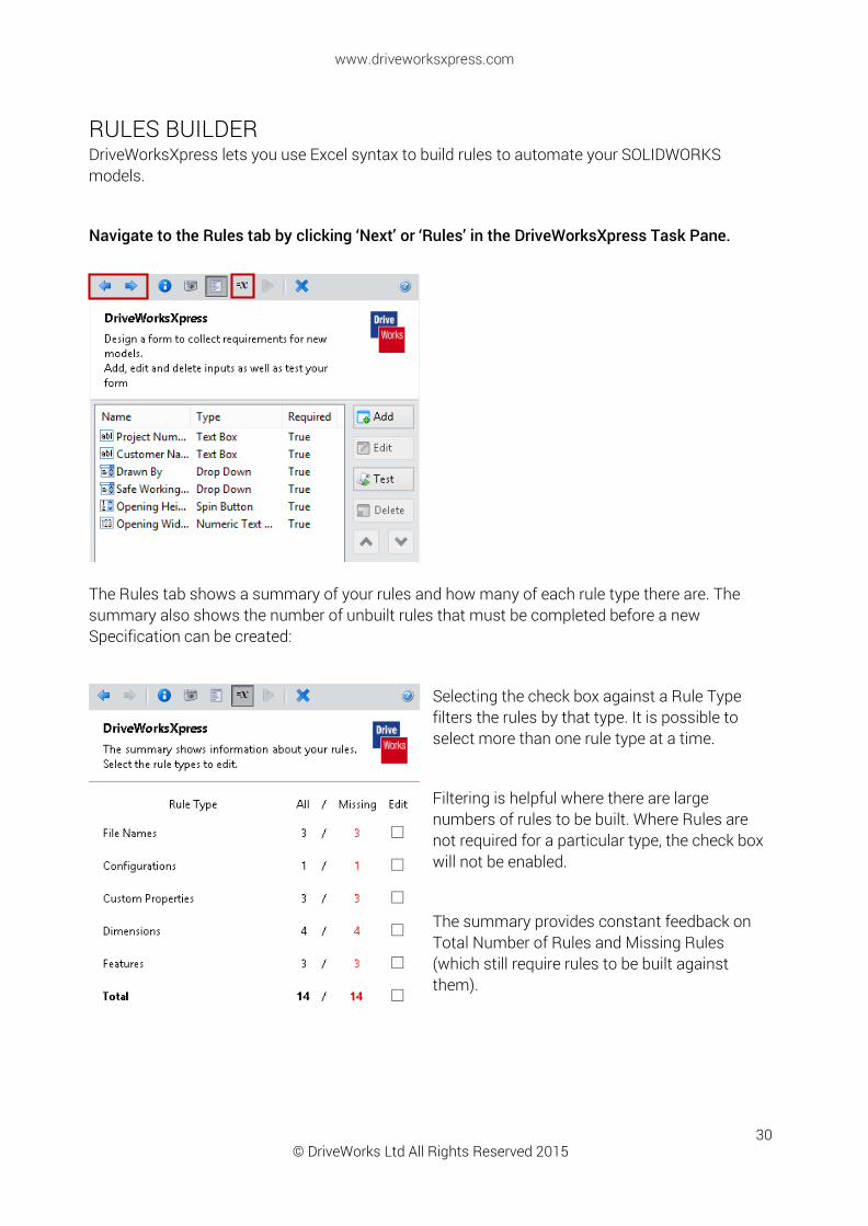
RULES BUILDER DriveWorksXpress lets you use Excel syntax to build rules to automate your SOLIDWORKS models.
Navigate to the Rules tab by clicking ‘Next’ or ‘Rules’ in the DriveWorksXpress Task Pane.
The Rules tab shows a summary of your rules and how many of each rule type there are. The summary also shows the number of unbuilt rules that must be completed before a new Specification can be created:
Selecting the check box against a Rule Type filters the rules by that type. It is possible to select more than one rule type at a time.
Filtering is helpful where there are large numbers of rules to be built. Where Rules are not required for a particular type, the check box will not be enabled.
The summary provides constant feedback on Total Number of Rules and Missing Rules (which still require rules to be built against them).
© DriveWorks Ltd All Rights Reserved 2015
www.driveworksxpress.com
31
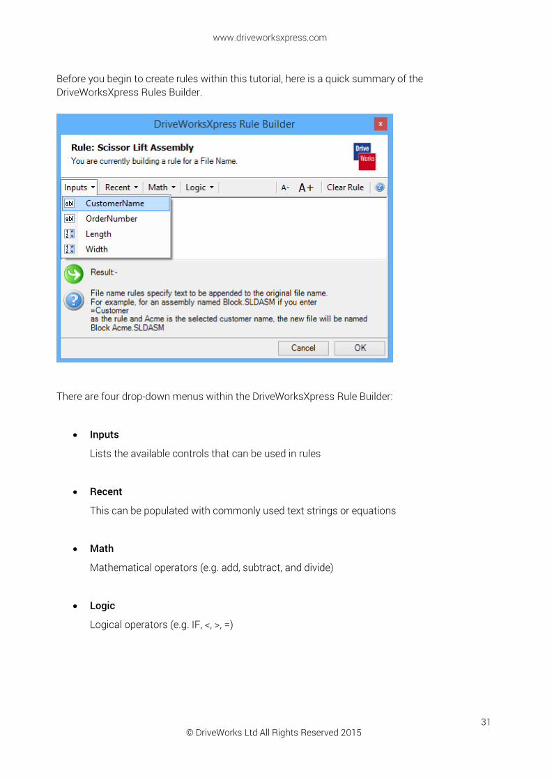
Before you begin to create rules within this tutorial, here is a quick summary of the DriveWorksXpress Rules Builder.
There are four drop-down menus within the DriveWorksXpress Rule Builder:
Inputs
Lists the available controls that can be used in rules
Recent
This can be populated with commonly used text strings or equations
Math
Mathematical operators (e.g. add, subtract, and divide)
Logic
Logical operators (e.g. IF, <, >, =)
© DriveWorks Ltd All Rights Reserved 2015
www.driveworksxpress.com
32
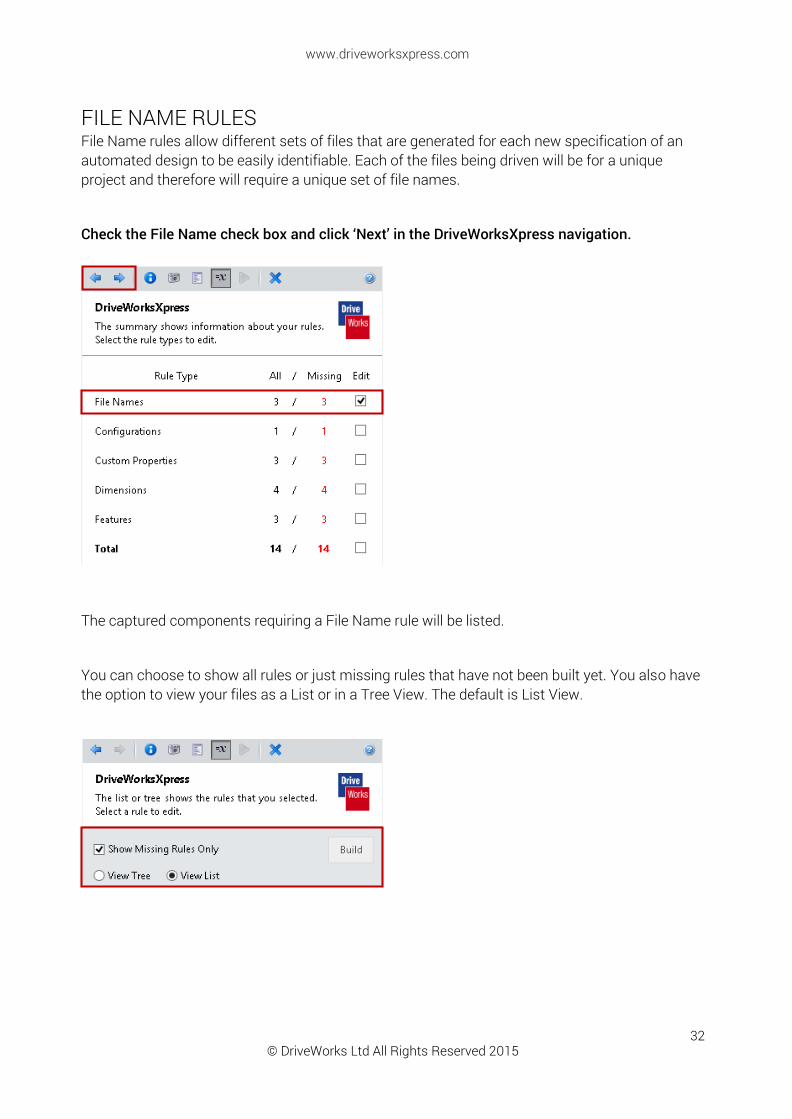
FILE NAME RULES File Name rules allow different sets of files that are generated for each new specification of an automated design to be easily identifiable. Each of the files being driven will be for a unique project and therefore will require a unique set of file names.
Check the File Name check box and click ‘Next’ in the DriveWorksXpress navigation.
The captured components requiring a File Name rule will be listed.
You can choose to show all rules or just missing rules that have not been built yet. You also have the option to view your files as a List or in a Tree View. The default is List View.

© DriveWorks Ltd All Rights Reserved 2015
www.driveworksxpress.com
33
BUILD A RULE FOR THE MOBILE GANTRY FILE NAME
Double click Mobile Gantry, the DriveWorksXpress Rules Builder Wizard will open.
Use the value Project Number so that every time a new mobile gantry specification is created it will be named based on the Project Number.
Click on the Inputs Value and select Project Number:
Name File Name Rule Mobile Gantry ProjectNumber
This rule will append the Project Number to the mobile gantry file name when you run your new specification.
Click ‘OK’ to return to the Rules Summary List.

© DriveWorks Ltd All Rights Reserved 2015
www.driveworksxpress.com
34
BUILD A RULE FOR THE UNIVERSAL BEAM FILE NAME Create a File Name rule for the Universal Beam based on the Opening Width and Safe Working Load. For example, if the value entered on your form for Opening Width is 2000 and the Safe Working Load is 500 Kg, the result of the rule for the file name of the Beam Assembly will be 2000 Wide - 500 Kg Safe Working Load
Double click Universal Beam and build the following File Name Rule:
Name File Name Rule Universal Beam OpeningWidth & " Wide - " & SafeWorkingLoad & " Safe Working Load"
BUILD A RULE FOR THE LEG FILE NAME As DriveWorks can reuse files previously created, you can build a library of standards. Use the height parameters to build up a text string as a means of identifying the file.
Use the Original File Name, then add the OpeningHeight & "high".
The completed rule should read: OpeningHeight & " high"
Double click Leg and build the following File Name Rule:
Name File Name Rule Universal Beam OpeningHeight & "high"
Click ‘Back’ in the DriveWorksXpress navigation to return to Rules Summary.

© DriveWorks Ltd All Rights Reserved 2015
www.driveworksxpress.com
35
CONFIGURATIONS RULES DriveWorksXpress does not create new configurations but it can be set to drive an existing file.
Un-check File Names and check Configurations. Click next in the DriveWorksXpress navigation.
The Universal Beam model has three configurations. The configurations allow the Safe Working Limit of the mobile gantry to be switched between 1500 Kg, 1000 Kg and 500Kg.
In order for DriveWorks to switch the configuration the exact name of the configuration must be entered in to the configuration rule.
Build a Rule for the Universal Beam Configuration:
Name Rule Configuration SafeWorkingLoad
Click ‘Back’ in the DriveWorksXpress navigation to return to Rules Summary.

© DriveWorks Ltd All Rights Reserved 2015
www.driveworksxpress.com
36
CUSTOM PROPERTY RULES You can capture and control Custom Properties in models using DriveWorksXpress. By linking drawing annotations to these Custom Properties, you can control drawing borders and notes.
Un-check Configurations and check Custom Properties. Click Next in the DriveWorksXpress Navigation.
Build a Rule for Drawn By using the Input Drawn By:
Name Rule Drawn By DrawnBy
Build a Rule for Safe Working Load using the Input Safe Working Load:
Name Rule Safe Working Load SafeWorkingLoad
Build a Rule for Project Number By using the Input Project Number:
Name Rule Project Number ProjectNumber
Click ‘Back’ in the DriveWorksXpress Navigation to return to Rules Summary.
© DriveWorks Ltd All Rights Reserved 2015
www.driveworksxpress.com
37
DIMENSION RULES Dimension rules allow you to automate your SOLIDWORKS models by taking information entered on the Form, calculating a result and then sending it to the SOLIDWORKS model. This allows you to control multiple dimesions at the same time using only a few inputs.
Un-check ‘Custom Properties’ and check ‘Dimensions’. Click next in the DriveWorksXpress navigation.
The tables below show the name of each dimension and the rule that should be created for that dimension.
Build a Rule for Leg Height using the Input OpeningHeight:
Name Rule Leg Height OpeningHeight
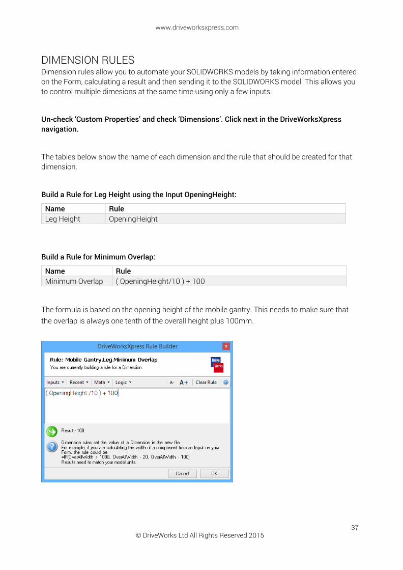
Build a Rule for Minimum Overlap:
Name Rule Minimum Overlap ( OpeningHeight/10 ) + 100
The formula is based on the opening height of the mobile gantry. This needs to make sure that the overlap is always one tenth of the overall height plus 100mm.
© DriveWorks Ltd All Rights Reserved 2015
www.driveworksxpress.com
38
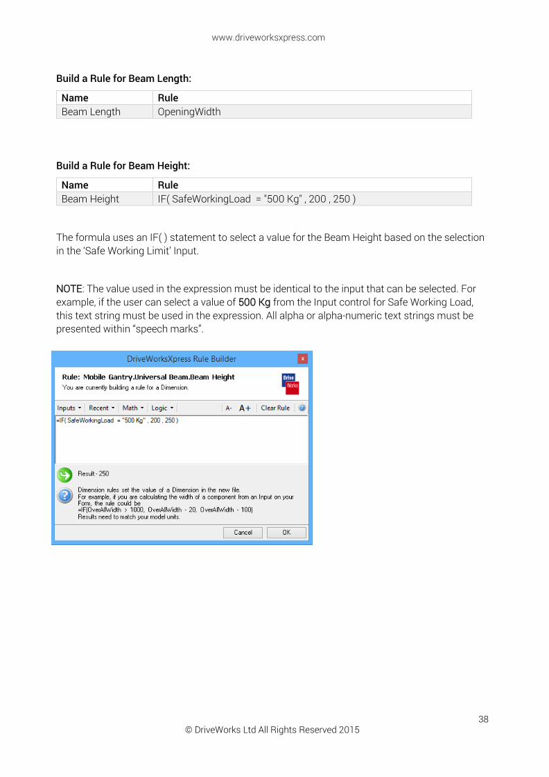
Build a Rule for Beam Length:
Name Rule Beam Length OpeningWidth
Build a Rule for Beam Height:
Name Rule Beam Height IF( SafeWorkingLoad = "500 Kg" , 200 , 250 )
The formula uses an IF( ) statement to select a value for the Beam Height based on the selection in the ‘Safe Working Limit’ Input.
NOTE: The value used in the expression must be identical to the input that can be selected. For example, if the user can select a value of 500 Kg from the Input control for Safe Working Load, this text string must be used in the expression. All alpha or alpha-numeric text strings must be presented within “speech marks”.
© DriveWorks Ltd All Rights Reserved 2015
www.driveworksxpress.com
39
BUILD RULES FOR FEATURE
Un-check ‘Dimensions’ and check ‘Features’. Click next in the DriveWorksXpress navigation.
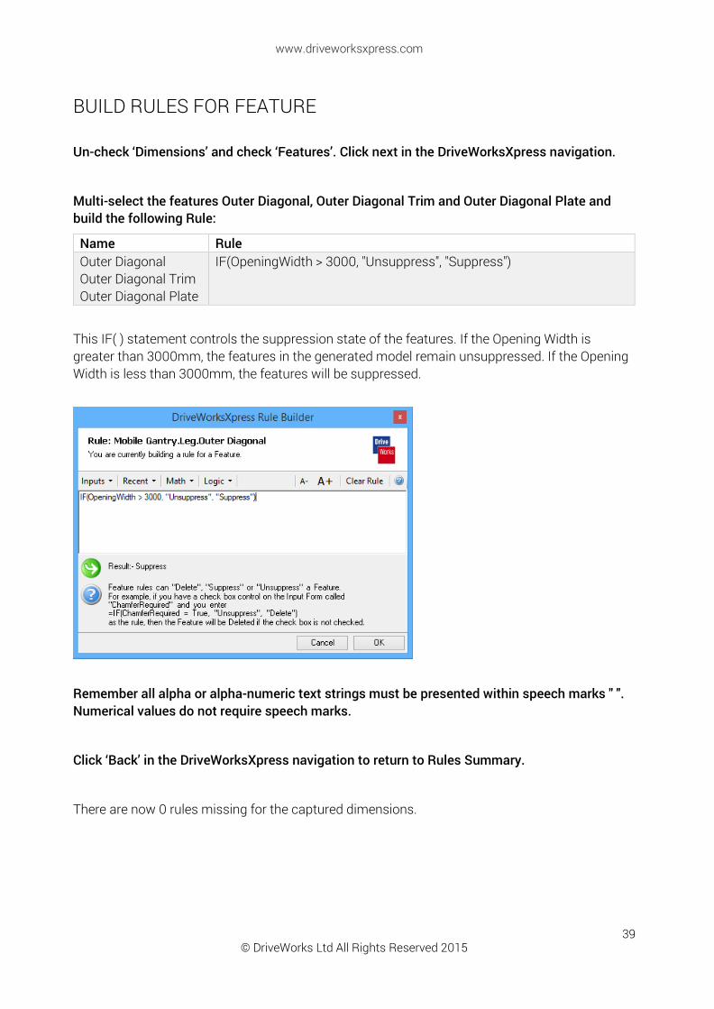
Multi-select the features Outer Diagonal, Outer Diagonal Trim and Outer Diagonal Plate and build the following Rule:
Name Rule Outer Diagonal Outer Diagonal Trim Outer Diagonal Plate
IF(OpeningWidth > 3000, "Unsuppress", "Suppress")
This IF( ) statement controls the suppression state of the features. If the Opening Width is greater than 3000mm, the features in the generated model remain unsuppressed. If the Opening Width is less than 3000mm, the features will be suppressed.
Remember all alpha or alpha-numeric text strings must be presented within speech marks " ". Numerical values do not require speech marks.
Click ‘Back’ in the DriveWorksXpress navigation to return to Rules Summary.
There are now 0 rules missing for the captured dimensions.
© DriveWorks Ltd All Rights Reserved 2015
www.driveworksxpress.com
40
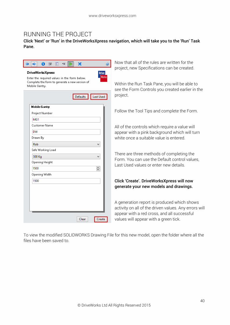
RUNNING THE PROJECT Click ‘Next’ or ‘Run’ in the DriveWorksXpress navigation, which will take you to the ‘Run’ Task Pane.
Now that all of the rules are written for the project, new Specifications can be created.
Within the Run Task Pane, you will be able to see the Form Controls you created earlier in the project.
Follow the Tool Tips and complete the Form.
All of the controls which require a value will appear with a pink background which will turn white once a suitable value is entered.
There are three methods of completing the Form. You can use the Default control values, Last Used values or enter new details.
Click ‘Create’. DriveWorksXpress will now generate your new models and drawings.
A generation report is produced which shows activity on all of the driven values. Any errors will appear with a red cross, and all successful values will appear with a green tick.
To view the modified SOLIDWORKS Drawing File for this new model, open the folder where all the files have been saved to.

© DriveWorks Ltd All Rights Reserved 2015
www.driveworksxpress.com
41
Congratulations! You have now completed this DriveWorksXpress Tutorial.
There is lots more downloadable content available at:
www.driveworksxpress.com
Now you’ve tried DriveWorksXpress, GO AUTOMATE your own SOLIDWORKS projects!