Embed Size (px)
Citation preview

2 LHM 550
160
0
20
40
60
80
100
120
140
0 5 10 15 20 25 30 35 40 45 50 55
Load diagram
Ca
pa
cit
y (
t)
Outreach (m)
on the ropes
motor grab
4-rope grab
Bo
om
fu
lcru
m 1
7.8
m
33
.7 m
Ab
ove
qu
ay m
ax.
45 m
(de
pe
nd
ing
on
gra
b)
Be
low
qu
ay
ap
pro
x. 15 m
13.5 m
Eye
le
ve
l 24.3
m
Main dimensions Bulk operation
150.000 DWT
Courtesy of Crane.Market
LHM 550 3
Bulk operation
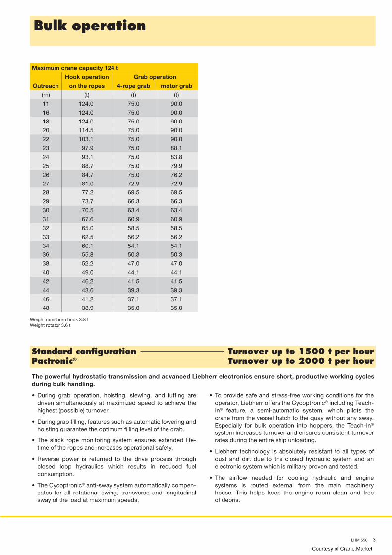
Maximum crane capacity 124 t
Hook operation Grab operation
Outreach on the ropes 4-rope grab motor grab
(m) (t) (t) (t)
11 124.0 75.0 90.0
16 124.0 75.0 90.0
18 124.0 75.0 90.0
20 114.5 75.0 90.0
22 103.1 75.0 90.0
23 97.9 75.0 88.1
24 93.1 75.0 83.8
25 88.7 75.0 79.9
26 84.7 75.0 76.2
27 81.0 72.9 72.9
28 77.2 69.5 69.5
29 73.7 66.3 66.3
30 70.5 63.4 63.4
31 67.6 60.9 60.9
32 65.0 58.5 58.5
33 62.5 56.2 56.2
34 60.1 54.1 54.1
36 55.8 50.3 50.3
38 52.2 47.0 47.0
40 49.0 44.1 44.1
42 46.2 41.5 41.5
44 43.6 39.3 39.3
46 41.2 37.1 37.1
48 38.9 35.0 35.0
Weight ramshorn hook 3.8 t
Weight rotator 3.6 t
The powerful hydrostatic transmission and advanced Liebherr electronics ensure short, productive working cycles
during bulk handling.
• During grab operation, hoisting, slewing, and luffing are
driven simultaneously at maximized speed to achieve the
highest (possible) turnover.
• During grab filling, features such as automatic lowering and
hoisting guarantee the optimum filling level of the grab.
• The slack rope monitoring system ensures extended life-
time of the ropes and increases operational safety.
• Reverse power is returned to the drive process through
closed loop hydraulics which results in reduced fuel
consumption.
• The Cycoptronic® anti-sway system automatically compen-
sates for all rotational swing, transverse and longitudinal
sway of the load at maximum speeds.
• To provide safe and stress-free working conditions for the
operator, Liebherr offers the Cycoptronic® including Teach-
In® feature, a semi-automatic system, which pilots the
crane from the vessel hatch to the quay without any sway.
Especially for bulk operation into hoppers, the Teach-In®
system increases turnover and ensures consistent turnover
rates during the entire ship unloading.
• Liebherr technology is absolutely resistant to all types of
dust and dirt due to the closed hydraulic system and an
electronic system which is military proven and tested.
• The airflow needed for cooling hydraulic and engine
systems is routed external from the main machinery
house. This helps keep the engine room clean and free
of debris.
Standard configuration Turnover up to 1500 t per hourPactronic® Turnover up to 2000 t per hour
Courtesy of Crane.Market

4 LHM 550
1 2 3 4 5 6 7 8 9 10 11 12 13 14 15 16 17 18
160
0
20
40
60
80
100
120
140
Ca
pa
cit
y (
t)
Load diagram
0 5 10 15 20 25 30 35 40 45 50 55
Outreach (m)
on the ropes
twin lift spreader
single lift spreader
Bo
om
fu
lcru
m 2
2.6
m
40
.7 m
Ab
ove
qu
ay m
ax.
45
mB
elo
w q
ua
y 1
5 m
13.5 m
Eye
le
ve
l 29.1
m
Main dimensions Container operation
Post-Panamax Container Liner
Courtesy of Crane.Market

LHM 550 5
Container operation
Weight rotator 3.0 t
Weight fully automatic (telescopic) spreader 9 t
Weight twin lift spreader 10.7 t
*) also available in 4-rope configuration
Weight rotator 3.6 t
Weight fully automatic (telescopic) spreader 9 t
Weight twin lift spreader 10.7 t
*) also available in 4-rope configuration
Precision to perfection: With incredibly short acceleration times for all crane motions, Liebherr is the top performer in
container handling.
• The crane can be fitted with various types of spreaders (fixed
or telescopic) connected to the rotator. Manual, semi or fully
automatic telescopic spreaders are available for various
container sizes.
• Liebherr Cycoptronic® is an accurate, sway-free load motion
control system that uses in-house designed software.
Cycoptronic® allows for direct load positioning and aids
the crane driver in mastering his task. With Cycoptronic®
turnover, safety and the confidence of the operator will be
improved.
• Safety: The luffing cylinder is positioned above the lattice
boom. This eliminates the possibility of any damage to the
cylinder through swinging loads or highly stowed rows of
containers on board the vessel.
• The Liebherr hydrostatic drive is the most reliable and
highest performing drive system for mobile harbour
cranes. Independent closed loop hydraulic systems utilize
the minimum number of components to guarantee highly
responsive, smooth and precise operation while maximizing
operational safety.
Maximum crane capacity 144 t*
Spreader operation under
Hook operation on the ropes
Outreach Single lift Twin lift Heavy lift
(m) (t) (t) (t)
11 41.0 50.0 144.0
12 41.0 50.0 144.0
13 41.0 50.0 144.0
14 41.0 50.0 144.0
16 41.0 50.0 144.0
18 41.0 50.0 144.0
20 41.0 50.0 144.0
22 41.0 50.0 130.5
24 41.0 50.0 117.9
26 41.0 50.0 107.2
28 41.0 50.0 97.7
30 41.0 50.0 89.2
32 41.0 50.0 82.3
34 41.0 50.0 76.0
36 41.0 50.0 70.7
38 41.0 50.0 66.0
40 41.0 47.7 62.0
42 41.0 44.1 58.4
44 41.0 40.9 55.2
45 41.0 39.4 53.7
48 36.7 35.0 49.3
50 33.8 32.1 46.4
52 31.0 29.3 43.6
54 28.3 26.6 40.9
Maximum crane capacity 104 t*
Spreader operation under
Hook operation on the ropes
Outreach Single lift Twin lift Heavy lift
(m) (t) (t) (t)
11 41.0 50.0 104.0
12 41.0 50.0 104.0
13 41.0 50.0 104.0
14 41.0 50.0 104.0
16 41.0 50.0 104.0
18 41.0 50.0 104.0
20 41.0 50.0 104.0
22 41.0 50.0 104.0
24 41.0 50.0 104.0
26 41.0 50.0 104.0
28 41.0 50.0 97.7
30 41.0 50.0 89.2
32 41.0 50.0 82.3
34 41.0 50.0 76.0
36 41.0 50.0 70.7
39 41.0 50.0 63.9
40 41.0 48.3 62.0
42 41.0 44.7 58.4
44 41.0 41.5 55.2
45 41.0 40.0 53.7
48 37.3 35.6 49.3
50 34.4 32.7 46.4
52 31.6 29.9 43.6
54 28.9 27.2 40.9
Standard configuration Turnover up to 32 cycles per hourPactronic® Turnover up to 38 cycles per hour
Courtesy of Crane.Market

6 LHM 550
Undercarriage
13.5 m
5.5 m13.5 m
6.0 m
1.8 m
longitudinally
diagonally
sideways
curves
slewing on the spot
Optimum pressure distribution and adaption
of wheel sets on uneven surfaces
Mobility• Outstanding mobility and manoeuvrability
• Curves at any possible radii and even slewing
on the spot
Modular propping system• Minimised stress and strain of undercarriage due to cruciform support
base which directs the load path from boom tip to quay
• Modular system allows further reduction of quay loads by installing
additional axle sets
• Easy adaptation to various sizes of support pads and bases
Hydraulic load distribution• Hydraulic suspension avoids overloading of individual wheel sets
• Standard trailer tyres making requisition of spares economical and
time-saving
• Increased lifetime of tyres due to individually steerable wheel sets
Schematic diagram
Courtesy of Crane.Market

LHM 550 7
Propping arrangementsStandard supporting base 13.5 m x 13.5 m
Standard pad dimension 4 x 5.5 m x 1.8 m
Standard supporting area of pads 9.9 m2
Optional size of supporting pads and bases on request
Quay load arrangements Bulk Container*
Uniformly distributed load 1.4 t/m2 1.6 t/m2
Max. load per tyre 5.6 t 5.8 t
Due to a unique undercarriage design the quay loads specified above can even
be reduced. Pad sizes, supporting base and the number of axle sets can easily
be adapted to comply with the most stringent quay load restrictions.
Technical data
Capacity and Classification Capacity Classification
Grab operation < 52 t A8
Standard operation < 77 t A6
Container < 63 t A7
Heavy lift < 144 t A3
Main dimensions Bulk Container*
Min. to max. outreach 11—48 m 11—54 m
Height of boom fulcrum 17.8 m 22.6 m
Tower cabin height (eye level) 24.3 m 29.1 m
Overall height (top of tower) 33.7 m 40.7 m
Overall length of undercarriage 20.7 m 20.7 m
Overall width of undercarriage 6.0 m 6.0 m
Number of axle sets (standard) 18 20
Number of axle sets (optional) 24 24
Working speedsHoisting / lowering 0 — 120 m/min
Slewing 0 — 1.6 rpm
Luffing 0 — 85 m/min
Travelling 0 — 5 km/h
Hoisting heights Bulk Container*
Above quay at minimum radius 45.0 m 45.0 m
Above quay at maximum radius 29.3 m 36.3 m
Below quay level 15.0 m 15.0 m
WeightTotal weight of crane
Bulk version with 48 m boom approx. 406 t
Total weight of crane
Container version with 54 m boom and
tower extension 4.8 m approx. 439 t
*) Crane with tower extension (4.8 m) and 54 m boom.
Optional equipment
1. Pactronic® - power by accumulator and electronics
2. Cycoptronic® - anti-sway system
3. Teach-In - semi-automatic point to point system
4. Sycratronic® - synchronizing crane control system
5. Vertical Line Finder - diagonal pull preventing system
6. Dynamic anti-collision system
7. Lidat® - basic package
8. Lidat® - tele service package
9. Lidat® - turnover package
10. SCULI - crane analyzer with various features
11. Economy software - for optimised fuel consumption
12. Video monitoring system
13. Radio remote control
14. Autopropping undercarriage
15. Cyclone air-intake system for the engine
16. Low temperature package
17. Customer-specific painting & logo
18. Additional (driven) axle sets
19. Axle sets equipped with foamed tyres
20. Different supporting bases and pad sizes
21. Tower extension 4.8 m
22. And many more as per customers´ requirements
Courtesy of Crane.Market

Liebherr-Werk Nenzing GmbH P.O. Box 10, A-6710 Nenzing/Austria Tel.: +43 50809 41-725 Fax: +43 50809 41-447 [email protected] www.liebherr.com
Practical solutions
Liebherr develops and produces special designs and solutions to meet customer-specific requirements
• The Liebherr Portal Crane, LPS, is an efficient combination
of a space-saving portal (mounted on rails) and the proven
mobile harbour crane concept. Particularly on narrow quays,
individual portal solutions permit (railway) trains and (road)
trucks to travel below the portal.
• Liebherr floating cranes, LBS, can be used for transhipment
and midstream operation between ocean-going vessels and
river barges on different types of waterways, including those
having no or few quays. In addition, the LBS solution allows
direct cargo transfer from ship to shore – especially when
quays reach capacity limits.
• Depending on customer specifications, the LBS range may
have varying lifting capacities due to tailor-made design
solutions.
• Liebherr Fixed Slewing Cranes (LFS) are an efficient
combination of a mobile harbour crane upper carriage and a
fixed pedestal. LFS cranes provide an economical and space-
saving solution for the installation on quaysides and jetties,
especially where room for manoeuvring is limited and low
ground pressure is essential. Additionally LFS solutions are
also ideally suited for the installation on crane barges.
LH
M 5
50 —
10
5410
68
—0
6/2
012—
Su
bje
ct
to c
ha
ng
e w
ith
ou
t n
oti
ce.
Powered by TCPDF (www.tcpdf.org)
Courtesy of Crane.Market