Embed Size (px)
Citation preview

BEU SYSTEM PRACTICES
AT& TCo Standard SECTION 461-220-100
Issue 2, August 1980
MOBILE HOME WIRING PERMANENT TYPE
I. GENERAL
1.01 This section provides wiring information for use in providing telephone service to mobile
homes.
1.02 This section is reissued to:
• Remove use of No. 14 ground wire
• Add use of 188A test set
• Revise text.
Since this reissue covers a general revision, arrows ordinarily used to indicate changes have been omitted.
1.03 A permanent type mobile home is a full-time residential structure, seldom moved, usually
set on supports such as jacks or concrete blocks,
with or without decorative skirting. Sizes range from 8 feet, or more, wide (most often 12 or 14 feet) by 35 feet, or more, long. Some mobile homes may consist of two single units, situated side by side, with the exterior covering designed to give the appearance of a conventional home. Mobile homes are sometimes used as business or field offices and may be equipped with key telephone systems.
1.04 Refer to Section 518-010-105 for key telephone system grounding and special protection
requirements. For telephone wiring information of recreational vehicles, which are smaller than mobile homes and designed to be frequently moved, refer to Section 461-220-101. Refer to Section 460-100-400 for additional information on station protection and grounding.
The following procedures must be followed in the order given when wiring a mobile home:
(1) Survey the site and make safety tests. Especially test the mobile home skin for
foreign voltages using the 188A test set.
(2) Install the protector.
(3) Ground the protector. Bond the protector and power grounds.
(4) Bond the chassis of the mobile home to the protector ground terminal.
(5) Install service or drop wire, if necessary, and connect to the protector.
(6) Install wiring between the protector and the station.
1.05 The information in this section is provided in the order previously mentioned.
2. SITE SURVEY AND SAFETY TESTS
Defects in electrical equipment or wiring in a mobile home may energize the unit and present an electrical hazard to persons in or near it. If a hazardous condition is found to exist, the craft person must proceed no further until the supervisor has been informed and the condition corrected. Instances have occurred where the chassis of the mobile home has been connected to the "hot" side of the electrical wiring making it hazardous to touch or attempt to b o n d t o a t e lp h o n e g r o u n d . ALWAYS test the chassis and skin of a mobile home with the 188A test set or B voltage tester t o d e t e c t f o r e i g n h a z a r d o u s voltages. The craft person should inform the occupant or trailer
NOTICE
Not for use or disclosure outside the
Bell System except under written agreement
Printed in U.S.A.
BSP 461·220·100·i02_1980·08·01.jpg Scanned by Frank Harrell, (Cowboy Frank) Castle Rock. Colorado Oct 09, 2012 13:58:03
Page I

SECTION 461-220-100
park manager, if available, of any hazardous condition found.
2.01 Prior to proceeding with the installation, a preliminary survey of the area should be
made. Make shift pole lines and nonstandard clearances should be avoided. If unsatisfactory conditions are found, refer them to your supervisor before proceeding with the installation. Typical service connections to mobile homes are shown in Fig. 1 and 2.
2.02 Determine how the power is fed to the
mobile home and determine whether and how the power service is grounded. In trailer parks the power service is frequently grounded to a ground rod. Where the power is fed underground to the mobile home from the service equipment, note the approximate location of the feeder, so it can be avoided when it is necessary to bury service or ground wires or to drive ground rods or posts.
II;_ , : - I ----�- r- · -- L -.-d-==::0 PROTE CTOR I :'i2·�\�
\'":::��'�;-�:�� ' .1 . .. _ ___ : :i[ (PROVIDEDBY
-- ·- • _;�, CUSTOMER). OR
PROTECTOR MOUNT! NG
POST. MINIMUM
E BURIED OR HEIGHT ABOVE C SERVICE WIRE GROUND- 2 FT.
Caution: Before making contact with the mobile home, verify the presence or absence of hazardous voltage on the mobile home body and chassis, using the voltage tester. Where mobile homes consist of two single units that have been joined to form one unit, (double-wide mobile home) test the chassis and body of BOTH units. Refer to Section 081-705-101 for use of the B voltage tester or Section 081-705-102 for the 188A test set.
2.03 Select test points where paint will not act as an insulator, such as screwheads, chassis
bolts, or unpainted areas. Avoid cutting through paint; select an inconspicious location to avoid marring the appearance of the mobile home. A VOID BODILY CONTACT WITH THE MOBILE HOME DURING THIS OPERATION.
If the voltage tester indicates that any part of the mobile home is
Fig. 1-Typical Buried Service Distribution
Page 2
BSP 461·220·100·i02_1980·08·02.jpg Scanned by Frank Harrell, (Cowboy Frank) Castle Rock, Colorado Oct 09, 2012 13:58:22

ISS 2, SECTION 461-220-100
Fig. 2-Typical Aerial Service Distribution
energized, do not proceed until the supervisor is notified and the condition corrected. Also, inform the occupant and/or trailer park manager of any hazardous condition found.
2.04 If the power has not yet been connected to the mobile home, request that it not be
connected until the telephone installation has been completed. Be aware of any connections being made while telephone work is in progress.
3. INSTAUING STATION PROTECTOR
3.01 The protector should be located as near as possible to the mobile home, preferably
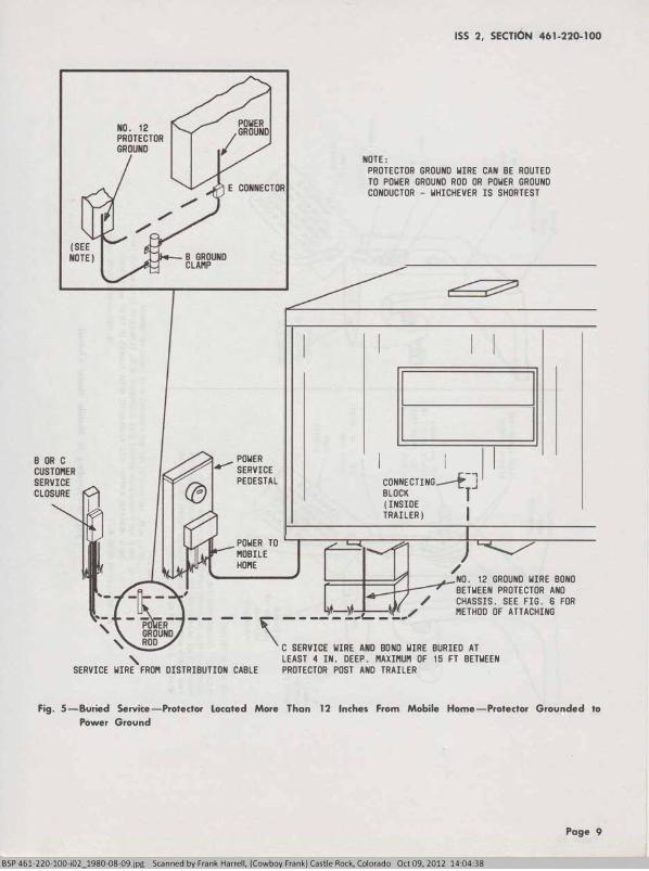
within 12 inches but not more than 15 feet away (Fig. 3, 4, and 5). Do not attach to or mount anything on the outside surface (skin) of the mobile home as the skin may be easily damaged and cause interior damage to the mobile home if penetrated.
3.02 When the service wire feeding the mobile home is buried service wire and it terminates
more than 15 feet away, it will be necessary to extend it to the protector location. For below ground splicing, use the 15-type service wire splice enclosure, the C service wire closure, or other equivalent closure. For above ground splices, the RC 4/72 cable closure may be used.
3.03 The telephone protector may be mounted on the following:
(a) A wood post that has been installed by the customer or construction
(b) A wood post used for mounting the power service equipment or meter
(c) A metal power service conduit
(d) A telephone company-provided protector mounting post (PMP)
Page 3
BSP 461-220-100-i02 1980-08-03.jpg Scanned by Frank Harrell, (Cowboy Frank) Castle Rock, Colorado Oct 09, 2012 13:5'!_'8: <+.47'--�-----�-----

SECTION 461-220-100
(e) An acceptable metallic water pipe (at least 10 feet must be buried).
3.04 Use B or C customer service closures for mounting protectors. The B closure mounts
one 123- or one 128-type protector. The C closure mounts two 123- or 128-type protectors, or one 106C (fused-type) protector.
4. GROUNDING PROTECTOR
4.01 Refer to Table A for selection of protector grounds. For a mobile home, the best
ground is usually the power ground system since acceptable water pipes and other approved grounds frequently do not exist. Where the power system is not multigrounded neutral (MGN) and is grounded to a ground rod, it will be necessary to install a telephone ground rod for grounding the protector. To obtain the lowest resistance ground, the telephone ground rod should be driven at least 6 feet away from the power ground rod. The two ground rods must then be bonded together with No. 6 ground wire.
4.02 When a ground rod is installed for a protector ground, rubber gloves must be worn while
driving the ground rod. Avoid bodily contact with the ground rod during this operation. After driving the ground rod, the voltage tester must be used to verify that no voltage condition exists on ground rod. If voltage is detected on the ground rod, do not proceed until the supervisor is notified and the condition corrected.
4.03 The protector should be grounded with No. 12 or larger ground wire. See Table B for
the proper size wire. The ground wire should be run to the grounding electrode in as short and straight a line as possible. Where the grounding electrode is not located near the protector mounting post, the ground wire must be buried to protect it. See Section 460-100-400 for detailed information on grounding hardware.
4.04 Separate grounding electrodes should always be bonded together to limit potential
differences between them and between their associated wiring systems. Whenever separate communication and power grounding electrodes are used, they should be bonded together with a No. 6 ground wire that is buried deep enough to protect it from physical damage (Fig. 4).
Page 4
If the telephone and power grounding systems are not bonded, a potential difference (probably large) will exist between the telephone and power wiring which may cause arcing when a voltage or lightning surge r aises the voltage on p o w e r and/or telephone wiring.
4.05 The customer telephone service may be installed where a power ground is not
provided. However, the customer should be informed immediately of the need for a power ground and should be requested to notify the telephone company when the ground has been provided. The procedure for notifying the customer shall be covered by local instructions. Where telephone service is already being furnished and there is no power ground, the same procedure should be followed. The telephone protector grounding electrode must be bonded to the power ground rod as soon as the power ground rod has been installed and connected.
5. BONDING CHASSIS TO PROTECTOR GROUND
Caution: The mobile home chassis must be bonded directly to the ground terminal post on the protector. This bond must be placed before attaching any other wiring to the mobile home and after the mobile home has been tested with the voltage tester.
5.01 Use No. 12, or larger, ground wire for bonding the mobile home chassis to the
protector ground terminal. For convenience, the bond wire can be the same size as the protector ground wire. This will permit the protector ground wire to be looped around the protector ground terminal and extended to the chassis to serve as a continuous bond wire as well. Use a B, C, or D insulator support (Fig. 6) to connect the bond wire to the chassis of the mobile home.
5.02 Where the protector is located within 12 inches of the mobile home, the bond wire
may be run directly across the space between the mounting post and the mobile home (Fig. 3 and 4). However, where the protector is located more than 12 inches from the mobile home, the ground wire must be run down the post using approved fasteners and buried at least 4-inches deep between the bottom of the post and the mobile home (Fig. 5).
BSP 461·220-100-i02_1980-08-04.jpg Scanned by Frank Harrell, (Cowboy Frank) Castle Rock, Colorado Oct 09, 2012 13:59:50

ISS 2, SECTION 461-220-100
TABLE A
NO
ADVISE CUSTOMER >----� TO HAVE POWER
ACCEPTABLE WATER
PIPE OR CONCRETE
ENCASED GROUND OR RING GROUND
AVAILABLE
BONO POWER SERVICE TO ACCEPTABLE WATER PIPE,
CONCRETE ENCASED GROUND
OR RING GROUND
CONNECT PROTECTOR GROUND TO POWER
SERVICE GROUND
SYSTEM (GROUND
WIRE, ENTRANCE CONDUIT, ROD) ,
COLD WATER PIPE,
OR BUILDING GROUND
WHICHEVER RESULTS IN SHORTEST
GROUND WIRE. BOND
OR VERIFY BOND
BETWEEN GROUNDS
GROUNDED
CONNECT PROTECTOR
GROUND TO ANY
PART OF POWER
SERVICE GROUND SYSTEM (GROUND
WIRE, ENTRANCE
CONDUIT, ROO) OR
COLD WATER PIPE
WHICH IS BONDED
TO POWER GROUND
WHICHEVER RESULTS
IN SHORTEST
GROUND WIRE
Leave the trench open when installing the bond wire because it can also be used for running the buried wire between the protector and the station. Make sure the bond wire and the wire to the station are buried far enough under the mobile home so they will not be damaged if the customer adds skirting or decorative blocks. If mobile home skirting or decorator blocks must be removed and replaced, this should be done by the customer.
Note: When digging is required to bury wire, use only tools with handles made of
CONNECT PROTECTOR
GROUND TO TELCO
GROUND ROD. BOND
TELCO GROUND ROD
TO POWER SERVICE
GROUND ROD.
ACCEPTABLE WATER
PIPE OR CONCRETE
ENCASED GROUND
OR RING GROUND
AVAILABLE
CONNECT PROTECTOR
GROUND TO COLD
WATER PIPE OR
BUILDING GROUND,
WHICHEVER RESULTS
IN SHORTEST
GROUND WIRE
NO
CONNECT PROTECTOR
GROUND TO TELCO
GROUND ROD.
wood or other insulating materials such as the B trenching tool to prevent electrical shock in case of contact with energized objects.
6. INSTALLING SERVICE OR DROP WIRE
6.01 Service to a mobile home may be a buried service wire or an aerial drop wire (Fig. 1
and 2).
6.02 Aerial drop wire must never be connected directly to the mobile home. Connections
Page S
BSP 461·220·100·i02_1980·08·05.jpg Scanned by Frank Harrell, (Cowboy Frank) Castle Rock, Colorado Oct 09, 2012 14:00:16

SECTION 461-220-100
TABLE B
GROUNDED WIRE CAPACITY
MAXIMUM NUMBER OF
GROUNDED WIRE SIZE PROTECTED Cl RCUITS
FUSE LESS FUSED
No. 1 2 2 6
No. 10 6 7
No.6 7 or more 8 or more
Note: The ground wire between protectors shall be the same size as the ground wire between the protector and the grounding electrode.
directly to the mobile home would require penetration of the skin permitting the entrance of moisture which could cause internal damage to the mobile home. The customer must provide a post having minimum dimensions of 4 inches by 4 inches and a minimum height of 10 feet above ground. All standard wiring clearances must be observed.
6.03 Buried service wire may be in place and terminated on a protector, or buried to
within close proximity of the mobile home and coiled. In the latter case, it will be necessary to terminate the buried service wire on a protector as described in Section 3. Before handling the unterminated buried service wire, test the shield with the voltage tester to make sure it is not energized. Test the skin and chassis of the mobile home for the same reason. If voltage is detected, proceed no further until supervision has been informed and the condition corrected.
6.04 When terminating service or buried wire on the protector, connect the shield of the wire
to the protector ground terminal with an F connector as shown in Fig. 7 and 8. Refer to Section 460-300-143 for detailed information on terminating buried wire.
7. WIRING BETWEEN PROTECTOR AND MOBILE
HOME
7.01 Construction of a typical mobile home is shown in Fig. 9. It is similar to a frame
building construction except it is mounted on a
Page 6
metal chassis. Telephone prewiring is not necessary, and the same wiring methods used for single family dwellings, built on-site, can be used for mobile homes.
7.02 The heating ducts, sewer and water pipes, and sometimes the electrical wiring run down
the center of the mobile home. Normally, the electrical wiring is in the outside walls of the mobile home, approximately 16 inches above the finished floor level or in the ceiling, leaving the floor area along the outside walls free for drilling for station wire entry. Drill straight down through plywood floor avoiding outriggers. Use care when drilling the soft insulating board (rodent barrier) covering the bottom of the mobile home as it tears easily. Seal holes with tape around station wire to prevent entrance of air and moisture. If it should be necessary to install a telephone on an interior wall of the mobile home, request the owner to provide the hole cautioning that prints of the floor area should be examined to determine where sewer lines, heating ducts, etc, are run. Since plastic pipes may be used, drills can easily penetrate them, causing damage.
7.03 Wiring runs should be attached to the outer edge of the outrigger so it will not be
necessary to crawl under the mobile home. Fasten insulator supports equipped with K bridle rings (or equivalent) to outer edge of outriggers. Attach wire to mobile home by 'running through bridle ring, folding back and taping, or clamping to insulator support with a B ground wire clamp or E drop wire clamp. At the protector, use the E drop wire clamp to attach service wire, or use the B ground wire clamp to attach station wire and the bonding wire, if required.
7.04 Where the protector is mounted within 12 inches of the mobile home, inside wiring
can be run directly to the protector and should be taped or fastened to the bond wire. Where the protector is located more than 12 inches from the mobile home, bury SK station wire or E buried wire at least 4-inches deep along with the bond wire between the protector and the mobile home. It is not necessary to connect the shield of the wire to the protector ground terminal. Cut off the metallic shield of the wire at both ends when terminating it. Tape any sharp edges of the shield to prevent personal injury.
BSP 461·220-100-i02_1980-08-06.jpg Scanned by Frank Harrell, (Cowboy Frank) Castle Rock, Colorado Oct 09, 2012 14:00:37

POWER
SERVICE
PEDESTAL
B OR C
CUSTOI'IER
SERVICE
CLOSURE
POWER
TO
I'IOBILE
"'"'\
' I'IAXIMUM """12 IN.
ISS 2, SECTION 461-220-100
II r-1 I I
CONNECTING _..ArJ BLOCK (INSIDE I TRAILER)
NO. 12 GROUND WIRE
BONDED TO TRAILER.
NO. 12 OR LARGER GROUND
WIRE BURIED AT LEAST
----- � SERVICE
SEE FIG. 6 FOR METHOD
OF ATTACHING. TAPE OR
TIE-WRAP STATION WIRE
TO GROUND WIRE FOR SUPPORT 4 IN. DEEP. CONNECT TO
POWER GROUND ROO OR
GROUND WIRE
WIRE
Fig. 3-Buried Service-Protector Located Witin 12 Inches of Mobile Home-Protector Grounded to Power
Ground
7.05 Wiring between the protector and the station should be terminated on a connecting block
mounted inside the mobile home. Use the connecting block as a bridging point for any extensions.
7.06 Always mount the block on a stud, if possible, as the thin materials used for trailer walls
may not hold the fasteners. Wall telephone sets
should also be mounted on a stud. Do not attempt to fish station wire through the mobile home walls as side rails and insulation will block passage of the wire. Studs can be located by sounding. A solid sound indicates a stud-a hollow sound indicates the area between studs. In the outrigger area, studs are 16 inches apart on centers.
Page 7
BSP 461-220-100-i02_1980-08-07.jpg Scanned by Frank Harrell, (Cowboy Frank) Castle Rock, Colorado Oct 09, 2012 14:00:58

SECTION 461 -220-100
\
GROUND ROD
' '
B OR C CUSTOI'IER SERVICE CLOSURE
' POWER TO
' ' / I'IOBILE HOI'IE
' ' , II' ' '
' '
' ' ,
' ' ' '
' ' ' ' ' , ' -
GROUND ROD� '' BONDED TOGETHER ' WITH NO. 6 WIRE ' BURIED AT LEAST '
4 IN. BY 4 IN. POST I'IINIMUI'I 10FT. ABOVE GROUND
I I ' MAXIMUM " 12 IN.
' 11 r-i CONNECTING/r
..J
BLOCK I (INSIDE TRAILER)
NO. 12 GROUND WIRE BONDED TO TRAILER.
4 IN. • ' ,_A_'!f,t,(J ,, TELEPHONE � GROUND ROO
SEE FIG. 6 FOR I'IETHOD OF ATTACHING. TAPE OR TIE-WRAP STATION WIRE TO GROUND WIRE FOR SUPPORT
Fig. 4-Aerial Service-Protector Located Within 12 Inches of Mobile Home-Separate Bonded Power and
Telephone Grounds
Page 8
BSP 461-220-100-i02 1980-08-08.jpg Scanned by Frank Harrell, (Cowboy Frank) Castle Rock, Colorado Oct 09, 2012 14:01:19
... _
.. _ '
' '
POWER ........-
SERVICE
PEDESTAL
ISS 2, SECTI6N 461-220-100
NOTE:
PROTECTOR GROUND WIRE CAN BE ROUTED
TO POWER GROUND ROD OR POWER GROUND
CONDUCTOR - WHICHEVER IS SHORTEST
I CONNECTING�-] 11 BLOCK T (INSIDE
TRAILER) I POWER TO L..,.----:--.--r----:;;::-----!--r-,.---:;-----MOBILE
HOME / NO. 12 GROUND WIRE BONO
BETWEEN PROTECTOR ANO
/ CHASSIS. SEE FIG. 6 FOR -),t / METHOD OF ATTACHING
- - \ �=�= ::-
: �0=-
WIRE BURIED AT
SERVICE WIRE FROM DISTRIBUTION CABLE
LEAST 4 IN. DEEP. MAXIMUM OF 15 FT BETWEEN
PROTECTOR POST AND TRAILER
Fig. 5-Buried Service-Protector Located More Than 12 Inches From Mobile Home-Protector Grounded to
Power Ground
Page 9
BSP 461·220-100-i02_1980-08-09.jpg Scanned by Frank Harrell, (Cowboy Frank) Castle Rock, Colorado Oct 09, 2012 14:04:38

� " ...
� � ... D 0 Ul '? ., s
I .... 0 "' 00 0 6 � 0 '0' "'
� "' Q_ � �
� � � -n 0 "' 0" �
I � ;;;-"' F-n 0 0 il Q_ 0
� 0 -"' N
� .... ... 0 "' 0 0
B, C, ORO INSULATOR SUPPORT (NOTE 2)
LOCATIOO FOR ADACHI NG GROOND Wl RE
INSTALL AS FOLLOWS:
PLACE GROUND WIRE BETWEEN WASHERS
10 mm X 38mm (5/16 X 1-1/2 IN.) GALV. STOVE BOLT (NOTE 1)
2mm
(NO. 12 OR LARGER) GROUND WIRE
FORM E-30138
PLACE BOLT THROUGH INSULATOR SUPPORT, INSTALL BOTIOM NUT ANO TIGHTEN. ATIACH INSULATOR SUPPORT TO OUTRIGGER IN USUAL MANNER. PLACE WASHERS ANO TOP NUT ON BOLT. REMCNE INSULATION FROM GROUND WIRE AND BEND BARE CONDUCTOR AROUND BOLT BETWEEN WASHERS. TIGHTEN TOP NUT.
NOTES' 1. BOLT, NUTS, AND WASHERS ARE NOT PRCNIDED WITH INSULATOR SUPPORT.
MOO I LE HOME OUTRIGGER
2. THE B AND D INSULATOR SUPPORT WILL ACCOMOOATE "'TAL FLANGES UP TO 19 mm(l/4 INC"). THE C INSULATOR SUPPORT WILL ACCO"'OOATE METAL FLANGES UP TO 25 rnm(1 INCH).
A. INSTALLATION USING BOLT B. INSTALLATION USING SCREW
Fig. 6-Bonding to Mobile Home Chassis
B, C, OR D INSULATOR SUPPORT (NOTE 2)
WASHER
10-24 X 19mm (3/4 IN.) SCREW
2mm (NO. 12 OR LARGER) GROUND WIRE
I'DRM E-lD13B

ISS 2, SECTION 461-220-100
BLACK
OUTER
JACKET I< - 5 1N.-Io l - I IN. r
SOLID POLYETHYLENE JACKET
BLACK
OUTER
JACKET
A-E BURIED WIRE
B-C SERVICE WIRE (20R5 PAIR)
Fig. 7 -Sheath Preparation for Placing F Connector
F CONNECTOR
A-E BURIED WIRE CONDU CTORS
F CONNECTOR
NOTE: THE COLOR CODE FOR 5 PAIR
C SERVICE WIRE CAN BE FOUND IN
SECTION 626·300-100 BK
8-C-SERVICE WIRE 12 OR 5 PAIRS)
Fig. 8-F Connector on Service Wire
G
BSP 461-220-100-i02 1980-08-1l.jQg Scanned by Frank Harrell, (Cowbo Frank) Castle Rock, Colorado Oct 09, 2012 14:05:20
Page 11

"' "' " ...
� ;::; � .... 0 Q '? "' s .. .. I .... "' 00 0 6 � '5· ""
g " " "' 0. � � OJ � � � n 0 " tT � � � ; ;;;-"' �R. n 0 0 OJ 0. 0
� 0 � "' � .... ... � :0. 0
.... Q "' CD
0,)
U/L SEAL
WIRE RACEWAY PROVIDED BY DADOES WITH STEEL PROTECTORS
FULL 2 X 3 STUDS 16" ON CENTER
2 X 5 FLOOR JOISTS;·CROSSBRACED TOP AND BOTTOM; BOLTED TO STEEL FRAME FOR UNITIZED CONSTRUCTION
ATTACH B BEAM CLIP S AND B SUPPORT INSULATOR TO O U TRIGGERS
Fig. 9-Typical Mobile Home Construction


![5. Wiring Diagram - Subaru Forester. Wiring Diagram A: POWER SUPPLY ROUTING SU01-04A 12 6-3 [D5A0] WIRING DIAGRAM 5. Wiring Diagram SU01-04B 13 WIRING DIAGRAM [D5A0] 6-3 5. Wiring](https://img.pdfslide.net/doc/110x75/5aa205fe7f8b9a1f6d8cac3f/5-wiring-diagram-subaru-wiring-diagram-a-power-supply-routing-su01-04a-12.jpg)