Embed Size (px)
Citation preview
Mobile NetworkEvolution to 5G
Vaasa goes 5G 17.5.2019
Matti KeskinenInternal ConsultantMobile Networks
NMTNordicMobile
Telephone
2
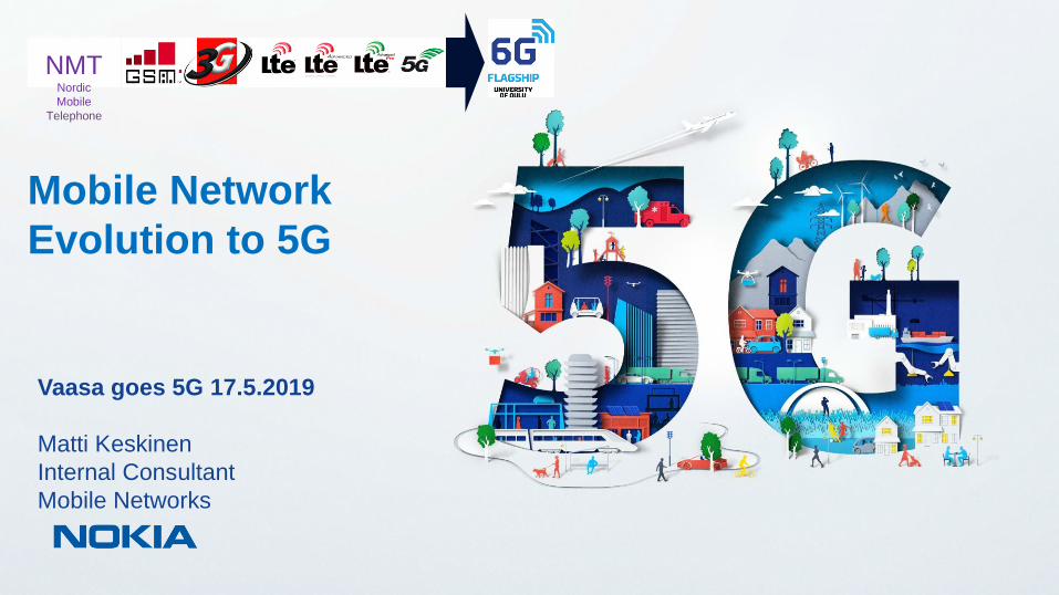
Mobile Networks Evolution in nutshell (Starting with old” Nokia solutions)
NMTNordic Mobile
Telephone
Analog Mobile Networks(”Old” Nokia solutions)
ARPAutoRadio
Puhelin
1980s 1990s 2000s 2010s 2020s ?1970s
Digital Mobile Networks
3rd Generation Partnership Project
…..10 years evolution cycle…..
Focustoday
3
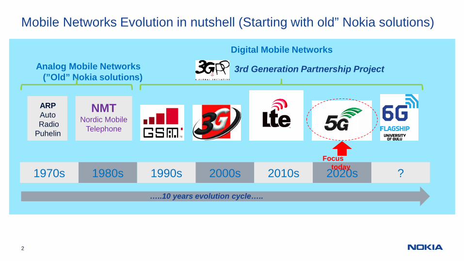
4th Industrial Revolution Powered by 5G
Industrial change
Economic flexibility &social mobility
Social & human impact
2nd Industrialrevolution
Electricity
Massproduction
3rd Industrialrevolution
IT
PCs, automation
1st Industrialrevolution
Steam
Mechanization
4th “Industrial”revolution
5G
Artificial intelligence, cloud,robotics, VR
People &Things
1770 1870 1970 2020Enabler
Driver
4 © Nokia Solutions and Networks 2014
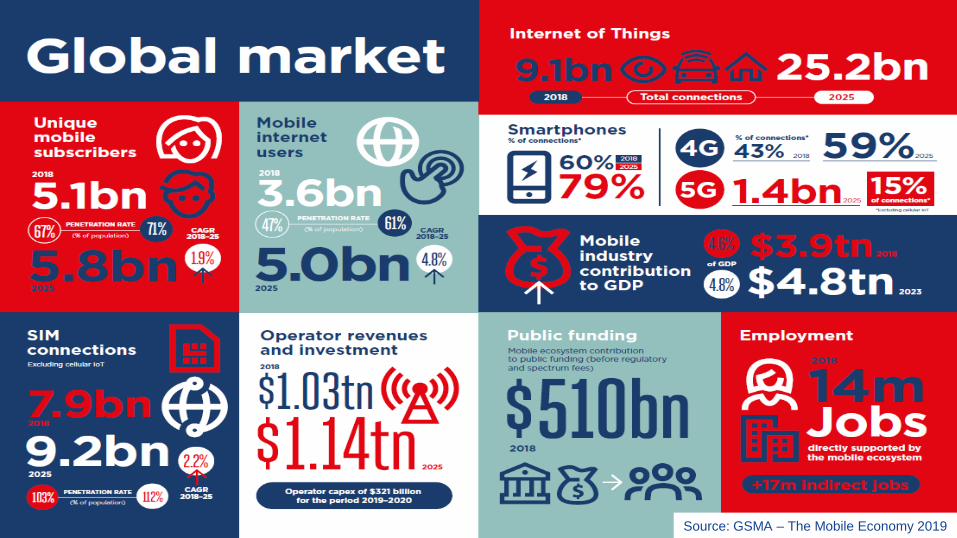
Source: GSMA – The Mobile Economy 2019
© 2016 Nokia5
Even 6G is knocking while 5G is just starting to ramp up
https://www.youtube.com/watch?v=T6ubRoZCeVw
Let start with short view to future:
Some history materialFrom “old” Nokia
7
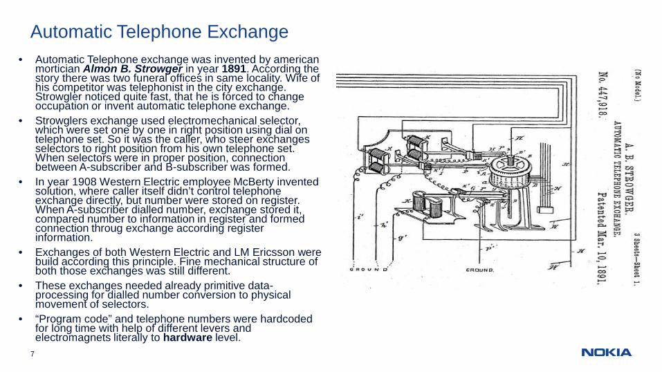
Automatic Telephone Exchange• Automatic Telephone exchange was invented by american
mortician Almon B. Strowger in year 1891. According thestory there was two funeral offices in same locality. Wife ofhis competitor was telephonist in the city exchange.Strowgler noticed quite fast, that he is forced to changeoccupation or invent automatic telephone exchange.
• Strowglers exchange used electromechanical selector,which were set one by one in right position using dial ontelephone set. So it was the caller, who steer exchangesselectors to right position from his own telephone set.When selectors were in proper position, connectionbetween A-subscriber and B-subscriber was formed.
• In year 1908 Western Electric employee McBerty inventedsolution, where caller itself didn’t control telephoneexchange directly, but number were stored on register.When A-subscriber dialled number, exchange stored it,compared number to information in register and formedconnection throug exchange according registerinformation.
• Exchanges of both Western Electric and LM Ericsson werebuild according this principle. Fine mechanical structure ofboth those exchanges was still different.
• These exchanges needed already primitive data-processing for dialled number conversion to physicalmovement of selectors.
• “Program code” and telephone numbers were hardcodedfor long time with help of different levers andelectromagnets literally to hardware level.
8
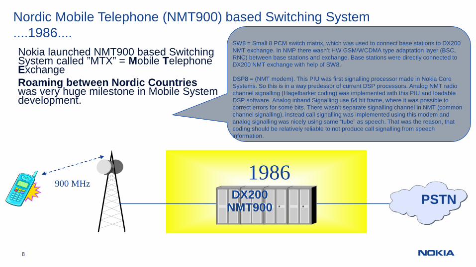
Nordic Mobile Telephone (NMT900) based Switching System....1986....Nokia launched NMT900 based SwitchingSystem called ”MTX” = Mobile TelephoneExchangeRoaming between Nordic Countrieswas very huge milestone in Mobile Systemdevelopment.
DX200NMT900
1986PSTN
SW8 = Small 8 PCM switch matrix, which was used to connect base stations to DX200NMT exchange. In NMP there wasn’t HW GSM/WCDMA type adaptation layer (BSC,RNC) between base stations and exchange. Base stations were directly connected toDX200 NMT exchange with help of SW8.
DSP8 = (NMT modem). This PIU was first signalling processor made in Nokia CoreSystems. So this is in a way predessor of current DSP processors. Analog NMT radiochannel signalling (Hagelbarker coding) was implemented with this PIU and loadableDSP software. Analog inband Signalling use 64 bit frame, where it was possible tocorrect errors for some bits. There wasn’t separate signalling channel in NMT (commonchannel signalling), instead call signalling was implemented using this modem andanalog signalling was nicely using same “tube” as speech. That was the reason, thatcoding should be relatively reliable to not produce call signalling from speechinformation.
900 MHz
9
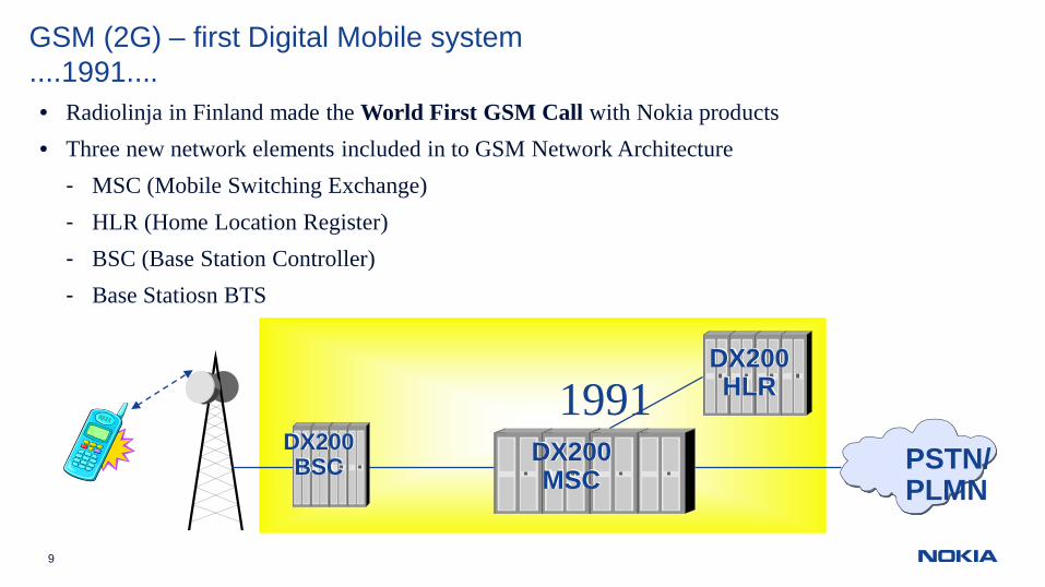
GSM (2G) – first Digital Mobile system....1991....• Radiolinja in Finland made the World First GSM Call with Nokia products• Three new network elements included in to GSM Network Architecture
- MSC (Mobile Switching Exchange)- HLR (Home Location Register)- BSC (Base Station Controller)- Base Statiosn BTS
DX200MSC
1991PSTN/PLMN
DX200BSC
DX200HLR
10
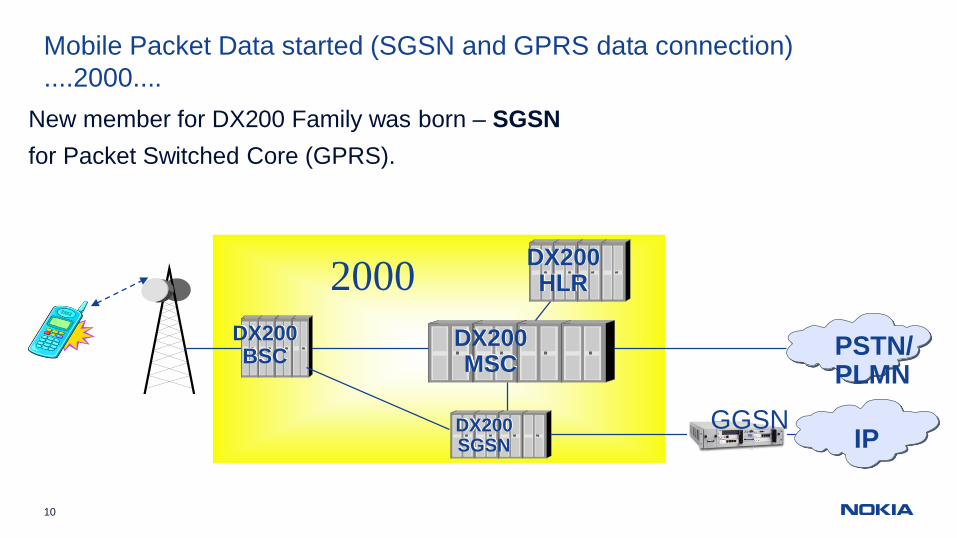
Mobile Packet Data started (SGSN and GPRS data connection)....2000....
New member for DX200 Family was born – SGSNfor Packet Switched Core (GPRS).
DX200MSC
2000PSTN/PLMN
DX200BSC
DX200HLR
DX200SGSN IP
GGSN
11
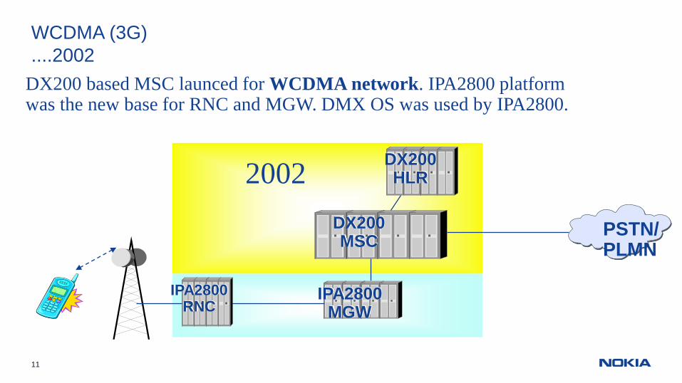
WCDMA (3G)....2002
DX200 based MSC launced for WCDMA network. IPA2800 platformwas the new base for RNC and MGW. DMX OS was used by IPA2800.
DX200MSC
2002
PSTN/PLMN
DX200HLR
IPA2800MGW
IPA2800RNC
12
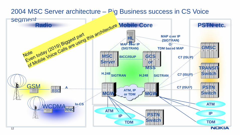
2004 MSC Server architecture – Big Business success in CS Voicesegment
HLR
GCSor
MSSSIGTRAN
MGWC7 (ISUP)
H.248
MSCServer
SIGTRAN
MGW
H.248
MAP over IP(SIGTRAN)
PSTNSwitch
TRANSITSwitch
GMSC
C7 (ISUP)
C7 (ISUP)
ATM, IPor TDM
BICC/ISUP
MAP over IP(SIGTRAN)
OrTDM based MAP
ATM
IP
TDM
Iu-CS
ABSC
RNC
GSM
WCDMA
Radio R4 Mobile Core PSTN etc.
TDMIP
ATMPSTN
Switch
14
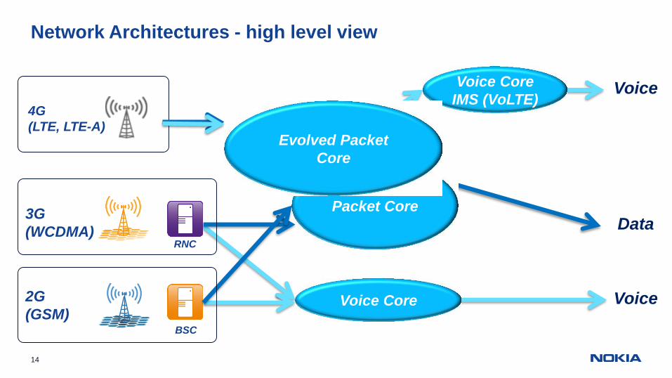
BSC
RNC
Packet Core
Voice Core
Data
Voice
3G(WCDMA)
2G(GSM)
4G(LTE, LTE-A)
Voice CoreIMS (VoLTE)
Voice
Evolved PacketCore
Network Architectures - high level view
15 © Nokia Solutions and Networks 2014
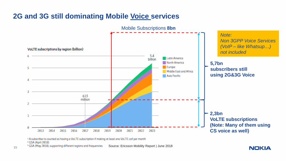
2G and 3G still dominating Mobile Voice services
Source: Ericsson Mobility Report | June 2018
Mobile Subscriptions 8bn
2,3bnVoLTE subscriptions(Note: Many of them usingCS voice as well)
5,7bnsubscribers stillusing 2G&3G Voice
Note:Non 3GPP Voice Services(VoIP – like Whatsup…)not included
16
0
50
100
150
200
2017 2018
Mobile data per day [PB]
China India USA EU
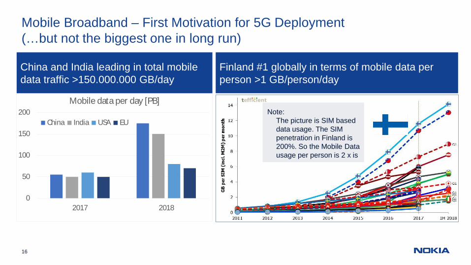
Mobile Broadband – First Motivation for 5G Deployment(…but not the biggest one in long run)
China and India leading in total mobiledata traffic >150.000.000 GB/day
Finland #1 globally in terms of mobile data perperson >1 GB/person/day
Note:The picture is SIM baseddata usage. The SIMpenetration in Finland is200%. So the Mobile Datausage per person is 2 x is
5G “in big picture”&
Standarization status
© 2016 Nokia18
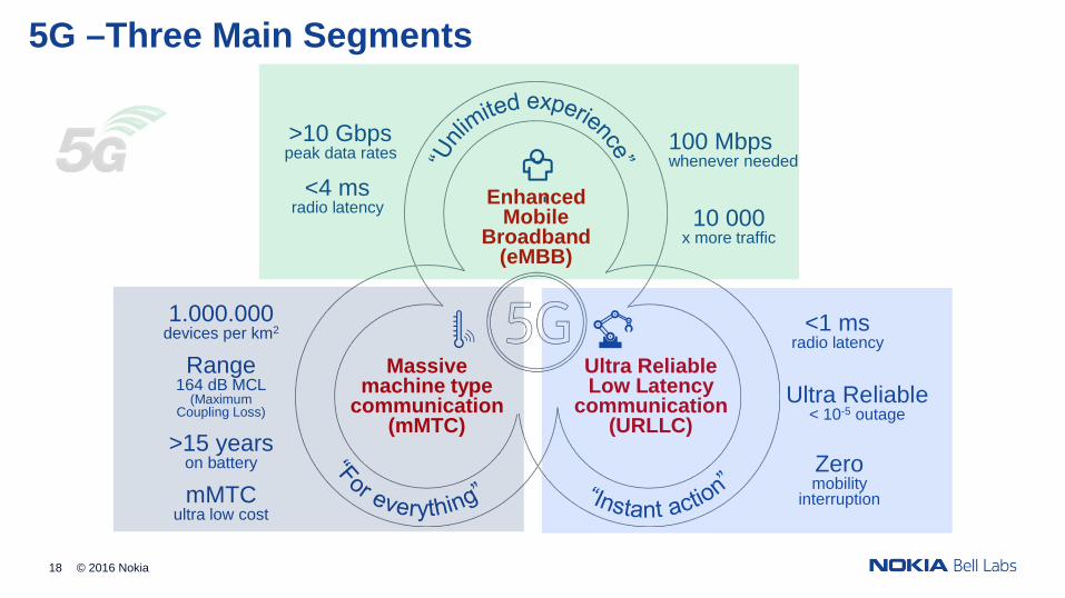
5G –Three Main Segments
Ultra Reliable< 10-5 outage
>15 yearson battery
100 Mbpswhenever needed
1.000.000devices per km2
10 000x more traffic
mMTCultra low cost
>10 Gbpspeak data rates
<1 msradio latency
Massivemachine type
communication(mMTC)
EnhancedMobile
Broadband(eMBB)
Ultra ReliableLow Latency
communication(URLLC)
Zeromobility
interruption
Range164 dB MCL
(MaximumCoupling Loss)
<4 msradio latency
© 2018 Nokia19 For Internal Use
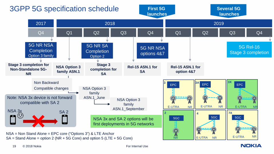
3GPP 5G specification schedule
Q4
2018
Q1 Q2 Q3 Q4
5G NR NSACompletionOption 3 family
5G NR SACompletion
Option 2
Stage 3 completion forNon-Standalone 5G-
NR
NSA Option 3family ASN.1
Stage 3completion for
SA
NSA = Non Stand Alone = EPC core (“Options 3”) & LTE AnchorSA = Stand Alone = option 2 (NR + 5G Core) and option 5 (LTE + 5G Core)
2017
NSA Option 3family
ASN.1_June NSA Option 3family
ASN.1_September
Non BackwardCompatible changes
2019
Q1 Q2 Q3 Q4
Rel-15 ASN.1 forSA
5G NR NSAoptions 4&7
Rel-15 ASN.1 foroption 4&7
5G Rel-16Stage 3 completion
First 5Glaunches
Several 5Glaunches
E-UTRA NR
EPC3A
E-UTRA NR
EPC3
E-UTRA NR
EPC3X
NRNR
5GC
2
E-UTRA NR
5GC4
E-UTRA
5GC7X
NSA 3x and SA 2 options will befirst deployments in 5G networks
NSA 3x SA 2
Note: NSA 3x device is not forwardcompatible with SA 2
20
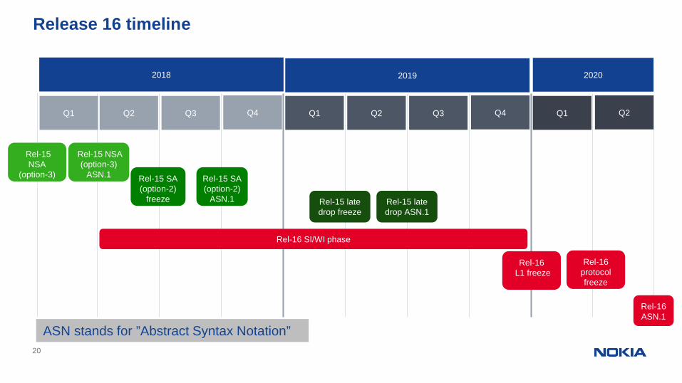
Release 16 timeline20
Q2 Q3 Q4
2019
Q2 Q3 Q4Q1
2020
Q1
Rel-16 SI/WI phase
Rel-16L1 freeze
Rel-15 SA(option-2)
freeze Rel-15 latedrop freeze
2018
Q1
Rel-15NSA
(option-3)freeze
Rel-15 NSA(option-3)
ASN.1 Rel-15 SA(option-2)
ASN.1 Rel-15 latedrop ASN.1
Q2
Rel-16protocolfreeze
Rel-16ASN.1
ASN stands for ”Abstract Syntax Notation”
21
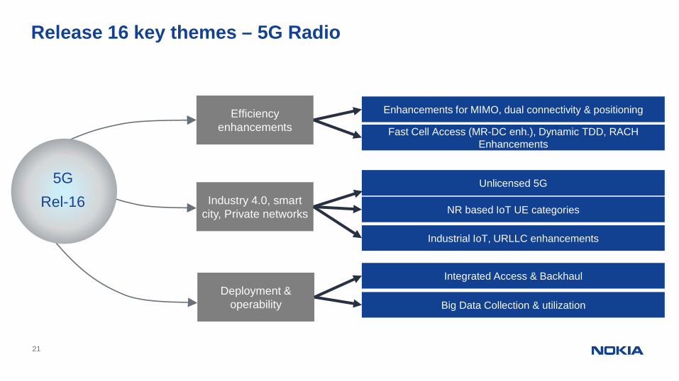
Release 16 key themes – 5G Radio
Industry 4.0, smartcity, Private networks
Deployment &operability
Efficiencyenhancements
Unlicensed 5G
NR based IoT UE categories
Enhancements for MIMO, dual connectivity & positioning
Industrial IoT, URLLC enhancements
Integrated Access & Backhaul
Fast Cell Access (MR-DC enh.), Dynamic TDD, RACHEnhancements
5GRel-16
Big Data Collection & utilization
22
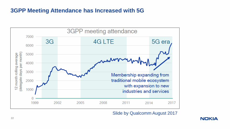
3GPP Meeting Attendance has Increased with 5G
Slide by Qualcomm August 2017
23 © 2018 Nokia
134
56
61
68
41
79
3931
194
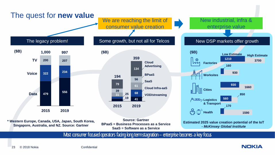
The quest for new value
Some growth, but not all for Telcos New DSP markets offer growthThe legacy problem!
* Western Europe, Canada, USA, Japan, South Korea,Singapore, Australia, and NZ. Source: Gartner
359
2015
CloudAdvertising
2019
VOD/streaming
Cloud Infra-aaS
SaaS
BPaaS
Health 1590
Factories
Worksites
Cities
Logistics& Transport
1660
850
1210
930
930
560
170
3700
Estimated 2025 value creation potential of the IoT- McKinsey Global Institute
Low Estimate High Estimate
Source: GartnerBPaaS = Business Processes as a Service
SaaS = Software as a Service
($B)($B) ($B)
1925
160
479556
234322
200 207
2015
1,000
556
234
207
2019
997
479
322
200
Data
Voice
TV
Most consumer focused operators facing long term stagnation – enterprise becomes a key focus
Confidential
We are reaching the limit ofconsumer value creation
New industrial, infra &enterprise value
© 2018 Nokia24
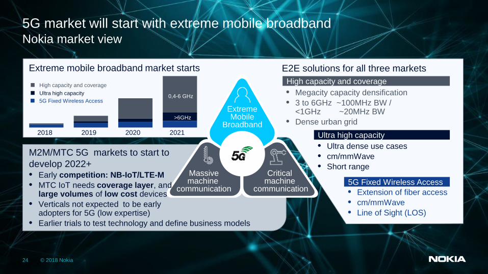
Nokia market view5G market will start with extreme mobile broadband
Massivemachine
communication
ExtremeMobile
Broadband
Criticalmachine
communication
M2M/MTC 5G markets to start todevelop 2022+• Early competition: NB-IoT/LTE-M• MTC IoT needs coverage layer, and
large volumes of low cost devices• Verticals not expected to be early
adopters for 5G (low expertise)• Earlier trials to test technology and define business models
20202018 2019 2021
>6GHz
0,4-6 GHz • Megacity capacity densification• 3 to 6GHz ~100MHz BW /
<1GHz ~20MHz BW• Dense urban grid
High capacity and coverageHigh capacity and coverageUltra high capacity5G Fixed Wireless Access
Extreme mobile broadband market starts E2E solutions for all three markets
5G Fixed Wireless Access• Extension of fiber access• cm/mmWave• Line of Sight (LOS)
• Ultra dense use cases• cm/mmWave• Short range
Ultra high capacity
5G Frequencies
26 © Nokia Solutions and Networks 2014
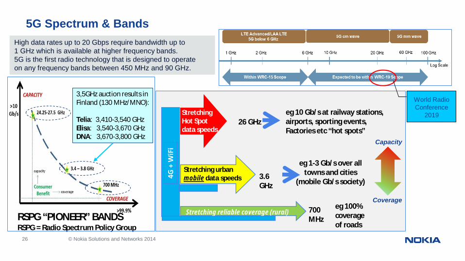
Stretching urbanmobile data speeds
StretchingHot Spotdata speeds
700MHz
3.6GHz
eg 1-3 Gb/s over alltowns and cities
(mobile Gb/s society)
eg 10 Gb/s at railway stations,airports, sporting events,Factories etc “hot spots”
26 GHz
eg 100%coverageof roads
Stretching reliable coverage (rural)RSPG “PIONEER” BANDSRSPG = Radio Spectrum Policy Group
5G Spectrum & BandsHigh data rates up to 20 Gbps require bandwidth up to1 GHz which is available at higher frequency bands.5G is the first radio technology that is designed to operateon any frequency bands between 450 MHz and 90 GHz.
World RadioConference
2019
Capacity
Coverage
3,5GHz auction results inFinland (130 MHz/MNO):
Telia: 3,410-3,540 GHzElisa: 3,540-3,670 GHzDNA: 3,670-3,800 GHz
27
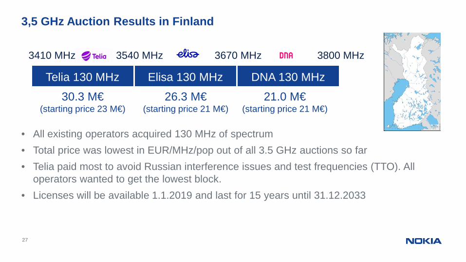
• All existing operators acquired 130 MHz of spectrum• Total price was lowest in EUR/MHz/pop out of all 3.5 GHz auctions so far• Telia paid most to avoid Russian interference issues and test frequencies (TTO). All
operators wanted to get the lowest block.• Licenses will be available 1.1.2019 and last for 15 years until 31.12.2033
3,5 GHz Auction Results in Finland
Telia 130 MHz Elisa 130 MHz DNA 130 MHz
3410 MHz 3540 MHz 3670 MHz 3800 MHz
30.3 M€(starting price 23 M€)
26.3 M€(starting price 21 M€)
21.0 M€(starting price 21 M€)
28
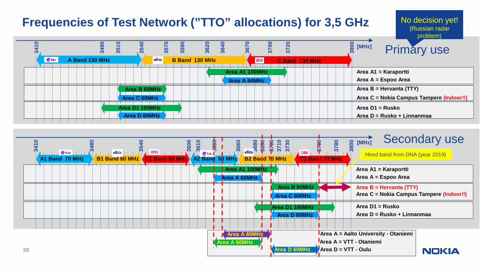
Frequencies of Test Network (”TTO” allocations) for 3,5 GHz34
10
3540
3800
3670
A Band 130 MHz B Band 130 MHz C Band 130 MHz
3620
3720
Area A1 100MHzArea A 60MHz
3640
3700
Area B 60MHzArea C 60MHz
3510
3570
Area D 60MHzArea D1 100MHz
3490
3590
Area A1 = KaraporttiArea A = Espoo AreaArea B = Hervanta (TTY)
Area D1 = RuskoArea D = Rusko + Linnanmaa
Area C = Nokia Campus Tampere (Indoor!!)
3410
3540
3800
3690
A1 Band 70 MHz C1 Band 60 MHz
3610
3730
Area A1 100MHzArea A 60MHz
3630
3710
Area B 60MHzArea C 60MHz
Area D 60MHzArea D1 100MHz
3480
3600
Area A1 = KaraporttiArea A = Espoo Area
Area B = Hervanta (TTY)
Area D1 = RuskoArea D = Rusko + Linnanmaa
Area C = Nokia Campus Tampere (Indoor!!)
B1 Band 60 MHz A2 Band 60 MHz C2 Band 70 MHzB2 Band 70 MHz
3660
3700
3760
3680
3780
Primary use
Secondary use
[MHz]
[MHz]
Hired band from DNA (year 2019)
Area A = Aalto University - Otaniemi
No decision yet!(Russian radar
problem)
Area A 60MHzArea A = VTT - OtaniemiArea A 60MHz
Area D 60MHz Area D = VTT - Oulu
29 © Nokia Solutions and Networks 2014
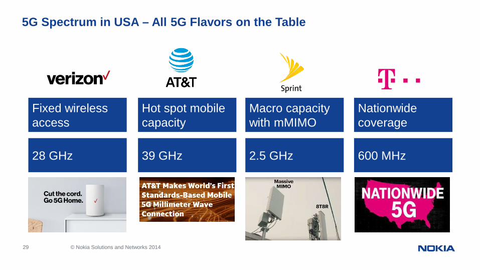
5G Spectrum in USA – All 5G Flavors on the Table
Fixed wirelessaccess
28 GHz
Hot spot mobilecapacity
39 GHz
Macro capacitywith mMIMO
2.5 GHz
Nationwidecoverage
600 MHz
5G Key componentsand
more about Architecture
31
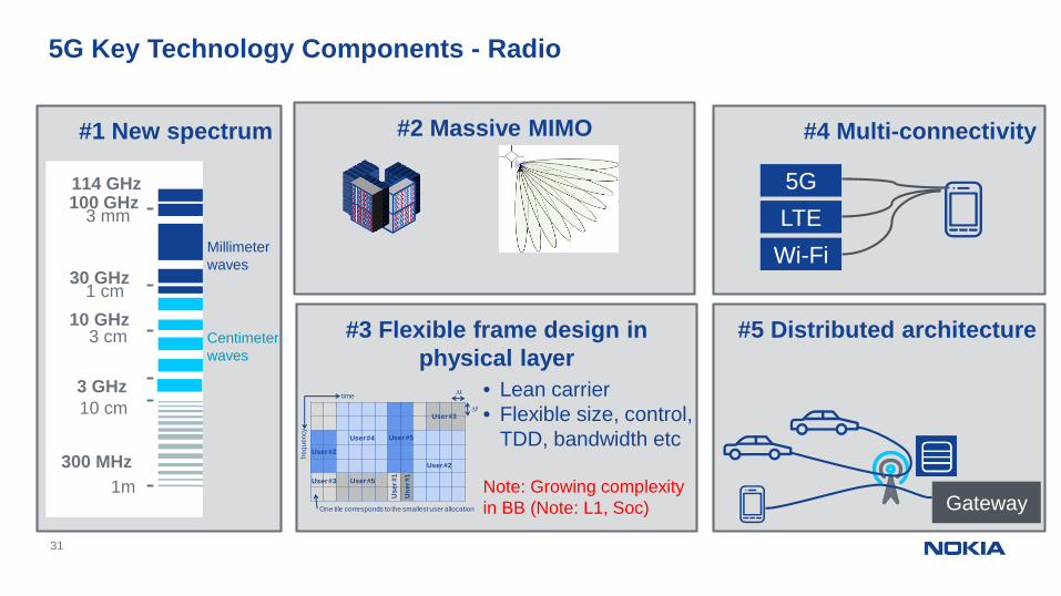
#2 Massive MIMO
5G Key Technology Components - Radio
#1 New spectrum
300 MHz
3 GHz
30 GHz
10 GHz
100 GHz
10 cm
1m
1 cm
3 mm
#3 Flexible frame design inphysical layer
User #3
User #2
User #5
User #2
User #4
Use
r #1
User #5
Use
r #1
time
frequ
ency
User #3
One tile corresponds to the smallest user allocation
Dt
Df
#4 Multi-connectivity
#5 Distributed architecture
Gateway
• Lean carrier• Flexible size, control,
TDD, bandwidth etc
Note: Growing complexityin BB (Note: L1, Soc)
5GLTE
Wi-Fi
3 cm
Millimeterwaves
Centimeterwaves
114 GHz
32 © Nokia 2018
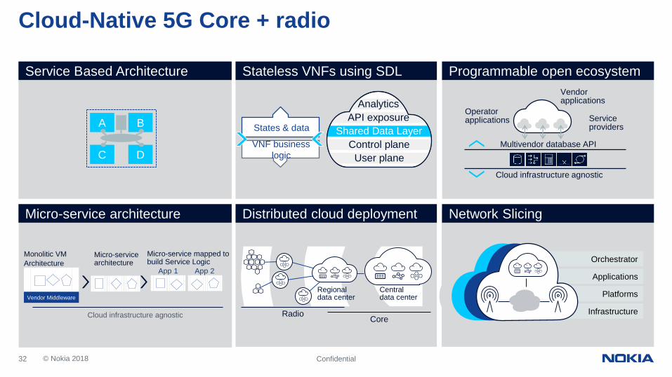
Cloud-Native 5G Core + radio
Confidential
Service Based Architecture Stateless VNFs using SDL
VNF businesslogic
States & data
Programmable open ecosystem
Shared Data LayerAPI exposure
Control planeUser plane
Analytics
Micro-service architecture Network Slicing
Monolitic VMArchitecture
Vendor Middleware
Micro-servicearchitecture
Micro-service mapped tobuild Service Logic
App 1 App 2
Distributed cloud deployment
Infrastructure
Orchestrator
Platforms
Applications
Cloud infrastructure agnostic
D
BA
C
Vendorapplications
Operatorapplications Service
providers
Cloud infrastructure agnostic
Multivendor database API
CoreRadio
Centraldata center
Regionaldata center
33
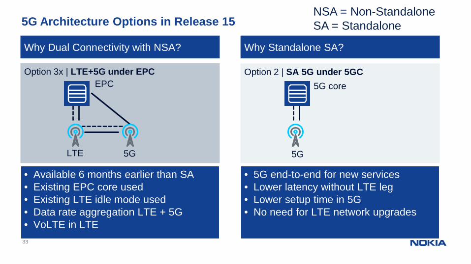
5G Architecture Options in Release 15
Option 2 | SA 5G under 5GC
5G
5G coreOption 3x | LTE+5G under EPC
5G
EPC
LTE
Why Dual Connectivity with NSA? Why Standalone SA?
• Available 6 months earlier than SA• Existing EPC core used• Existing LTE idle mode used• Data rate aggregation LTE + 5G• VoLTE in LTE
• 5G end-to-end for new services• Lower latency without LTE leg• Lower setup time in 5G• No need for LTE network upgrades
NSA = Non-StandaloneSA = Standalone
20/05/201934Nokia Confidential
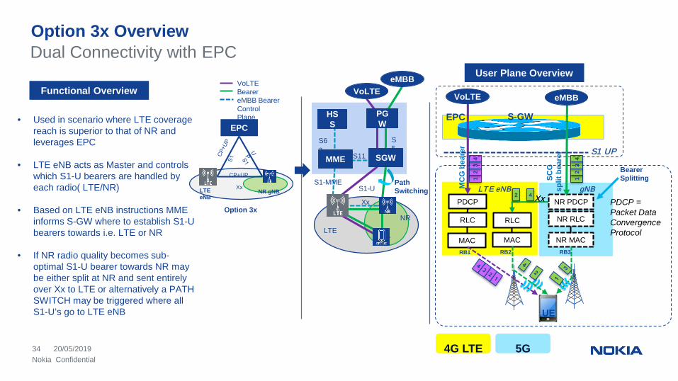
Option 3x OverviewDual Connectivity with EPC
SGW
VoLTE
PGW
eMBB
BearerSplitting
• Used in scenario where LTE coveragereach is superior to that of NR andleverages EPC
• LTE eNB acts as Master and controlswhich S1-U bearers are handled byeach radio( LTE/NR)
• Based on LTE eNB instructions MMEinforms S-GW where to establish S1-Ubearers towards i.e. LTE or NR
• If NR radio quality becomes sub-optimal S1-U bearer towards NR maybe either split at NR and sent entirelyover Xx to LTE or alternatively a PATHSWITCH may be triggered where allS1-U’s go to LTE eNB
HSS
MME
Xx
S1-US1-MME
S11
S5
S6a
Functional Overview
PathSwitching
VoLTEBearereMBB BearerControlPlane
LTE
NR
EPC
CP+UP
LTEeNB
NR gNBXx
Option 3xPDCP
RLC RLC
MC
Gbe
arer
SCG
split
bear
er
LTE eNB
MAC MAC
NR PDCP
NR RLC
NR MAC
gNB
S-GWEPC
Xx
S1 UP
12
34
12
34
UE
RB1 RB2 RB3
2 4
eMBBVoLTE
User Plane Overview
4G LTE 5G
PDCP =Packet DataConvergenceProtocol
Some details and comparisonbetween 4G - 5G
36 © Nokia 2017
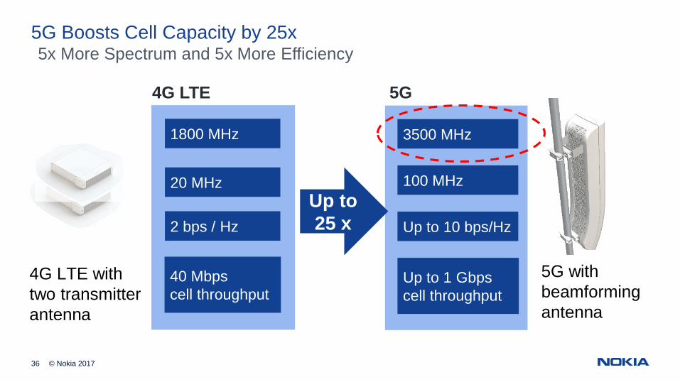
5G Boosts Cell Capacity by 25x
100 MHz
3500 MHz
Up to 10 bps/Hz
Up to 1 Gbpscell throughput
5G withbeamformingantenna
1800 MHz
20 MHz
2 bps / Hz
40 Mbpscell throughput
Up to25 x
5x More Spectrum and 5x More Efficiency
4G LTE 5G
4G LTE withtwo transmitterantenna
37 © Nokia 2017
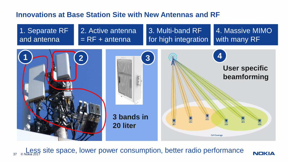
Innovations at Base Station Site with New Antennas and RF
2. Active antenna= RF + antenna
4. Massive MIMOwith many RF
1. Separate RFand antenna
1 2 4
3. Multi-band RFfor high integration
3 bands in20 liter
User specificbeamforming
Less site space, lower power consumption, better radio performance
3
38 © Nokia 2017
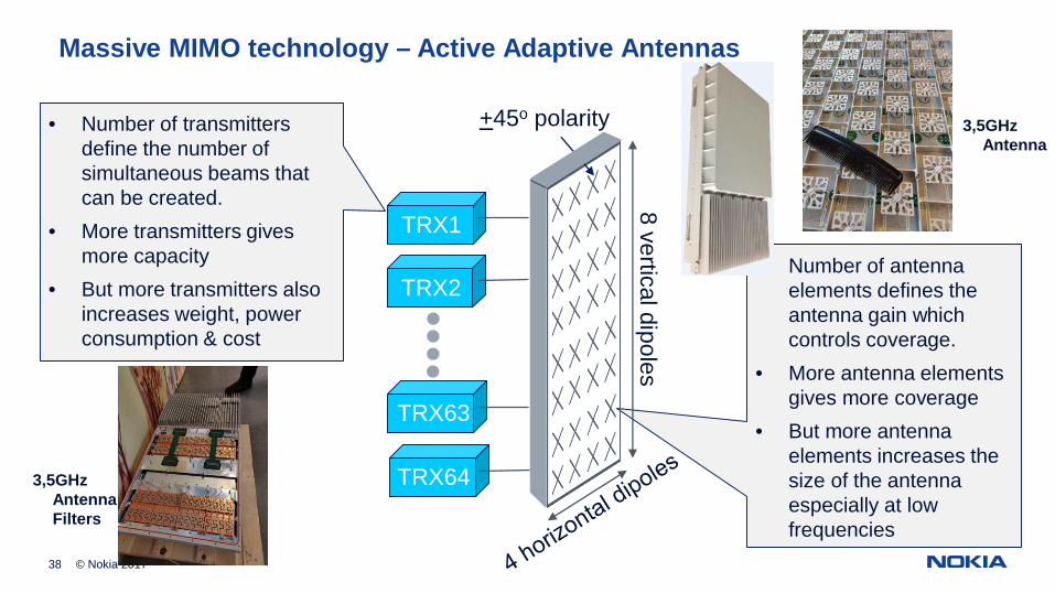
• Number of antennaelements defines theantenna gain whichcontrols coverage.
• More antenna elementsgives more coverage
• But more antennaelements increases thesize of the antennaespecially at lowfrequencies
8 vertical dipoles
+45o polarity
TRX1
TRX2
TRX63
TRX64
• Number of transmittersdefine the number ofsimultaneous beams thatcan be created.
• More transmitters givesmore capacity
• But more transmitters alsoincreases weight, powerconsumption & cost
Massive MIMO technology – Active Adaptive Antennas
3,5GHzAntennaFilters
3,5GHzAntenna
39 © Nokia 2017
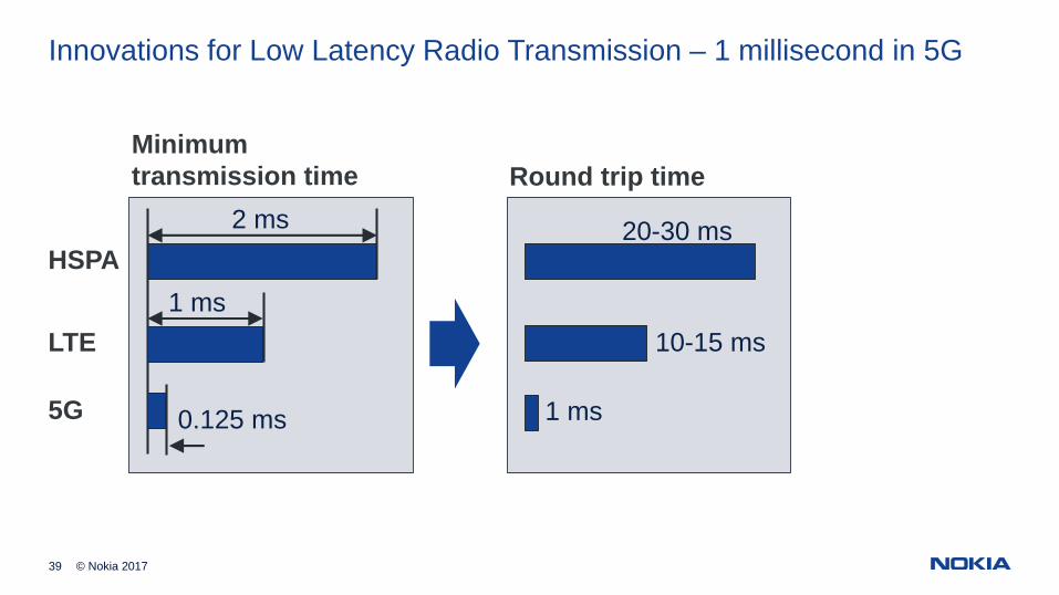
Innovations for Low Latency Radio Transmission – 1 millisecond in 5G
2 ms
0.125 ms
Minimumtransmission time
1 msHSPA
LTE
5G 1 ms
Round trip time
10-15 ms
20-30 ms
40 © Nokia Solutions and Networks 2014
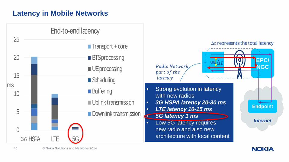
Latency in Mobile Networks
• Strong evolution in latencywith new radios
• 3G HSPA latency 20-30 ms• LTE latency 10-15 ms• 5G latency 1 ms• Low 5G latency requires
new radio and also newarchitecture with local content
0
5
10
15
20
25
HSPA LTE 5G
ms
End-to-end latency
Transport + core
BTS processing
UE processing
Scheduling
Buffering
Uplink transmission
Downlink transmission
EPC/NGC
UE
Endpoint
Internet
∆
∆ represents the total latency
ℎ
3
42
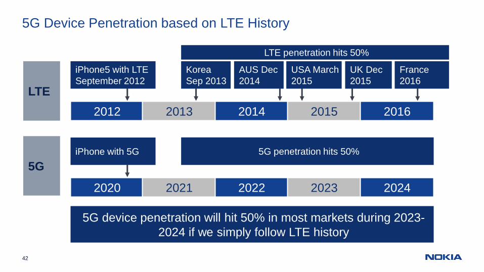
5G Device Penetration based on LTE History
2012 2013 2014 2015
iPhone5 with LTESeptember 2012
AUS Dec2014
LTE
5G
2016
USA March2015
France2016
KoreaSep 2013
UK Dec2015
2020 2021 2022 2023
iPhone with 5G
2024
LTE penetration hits 50%
5G penetration hits 50%
5G device penetration will hit 50% in most markets during 2023-2024 if we simply follow LTE history
45
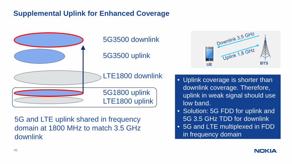
Supplemental Uplink for Enhanced Coverage
5G3500 downlink
5G3500 uplink
LTE1800 downlink
5G1800 uplink
• Uplink coverage is shorter thandownlink coverage. Therefore,uplink in weak signal should uselow band.
• Solution: 5G FDD for uplink and5G 3.5 GHz TDD for downlink
• 5G and LTE multiplexed in FDDin frequency domain
LTE1800 uplink
5G and LTE uplink shared in frequencydomain at 1800 MHz to match 3.5 GHzdownlink
UE BTS
46
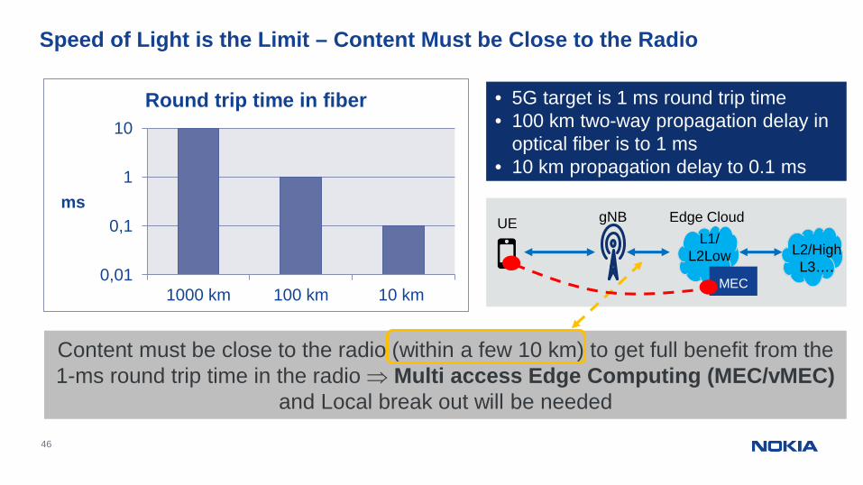
Speed of Light is the Limit – Content Must be Close to the Radio
0,01
0,1
1
10
1000 km 100 km 10 km
ms
Round trip time in fiber • 5G target is 1 ms round trip time• 100 km two-way propagation delay in
optical fiber is to 1 ms• 10 km propagation delay to 0.1 ms
Content must be close to the radio (within a few 10 km) to get full benefit from the1-ms round trip time in the radio Þ Multi access Edge Computing (MEC/vMEC)
and Local break out will be needed
Edge CloudL1/
L2Low
UE gNB
L2/HighL3….
MEC
47
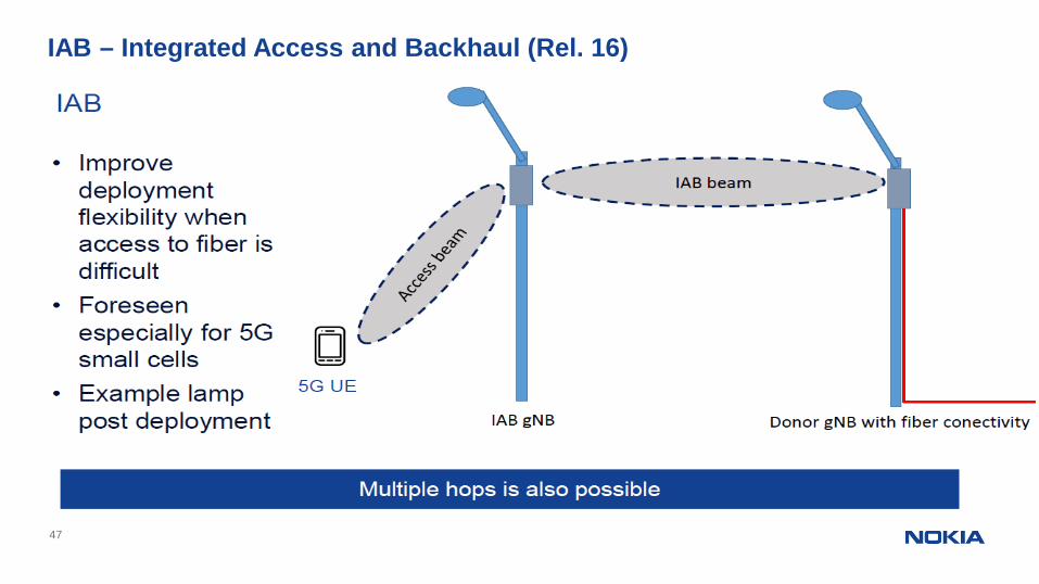
IAB – Integrated Access and Backhaul (Rel. 16)
© Nokia 2019
2018 2019 2020
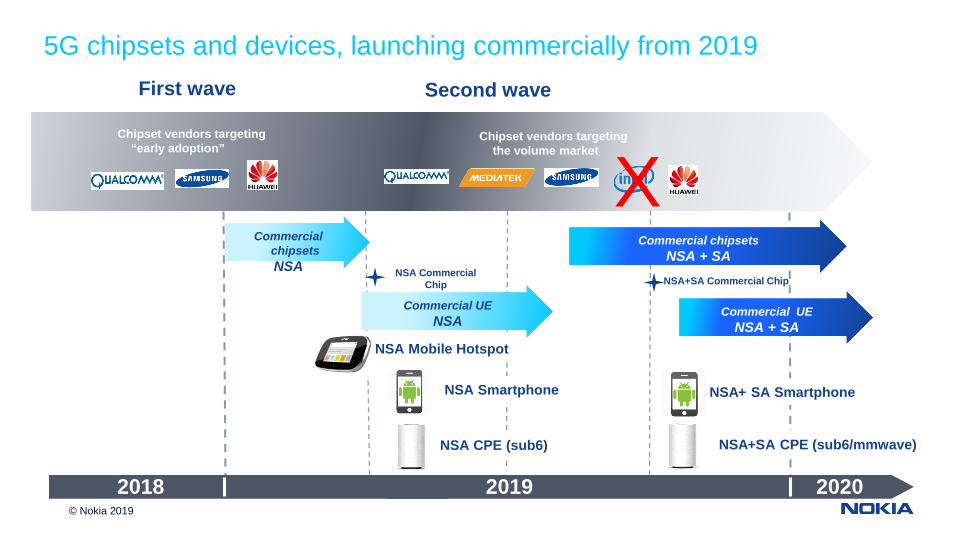
5G chipsets and devices, launching commercially from 2019First wave Second wave
NSA Smartphone NSA+ SA Smartphone
NSA Mobile Hotspot
NSA CPE (sub6)
Chipset vendors targeting“early adoption”
Chipset vendors targetingthe volume market
NSA+SA CPE (sub6/mmwave)
CommercialchipsetsNSA
Commercial chipsetsNSA + SA
Commercial UENSA
Commercial UENSA + SA
NSA CommercialChip NSA+SA Commercial Chip
X
49
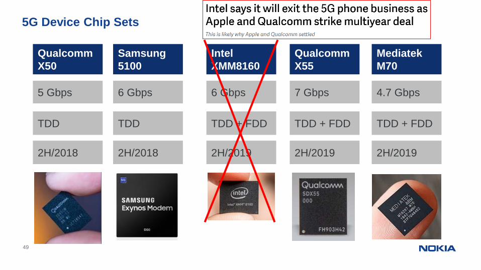
5G Device Chip Sets
QualcommX55
7 Gbps
TDD + FDD
QualcommX50
5 Gbps
TDD
2H/20192H/2018
IntelXMM8160
6 Gbps
TDD + FDD
2H/2019
MediatekM70
4.7 Gbps
TDD + FDD
2H/2019
Samsung5100
6 Gbps
TDD
2H/2018
Support 100 + 100 MHz
Radio going to Cloud
51
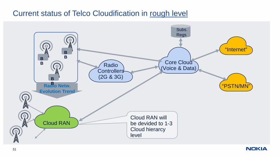
Current status of Telco Cloudification in rough level
Core Cloud(Voice & Data)
“Internet”
“PSTN/MN”
RadioControllers(2G & 3G)
Subs.Regs
Cloud RAN
Radio Netw.Evolution Trend
BB
BB
BB
Cloud RAN willbe devided to 1-3Cloud hierarcylevel
© 2019 Nokia52
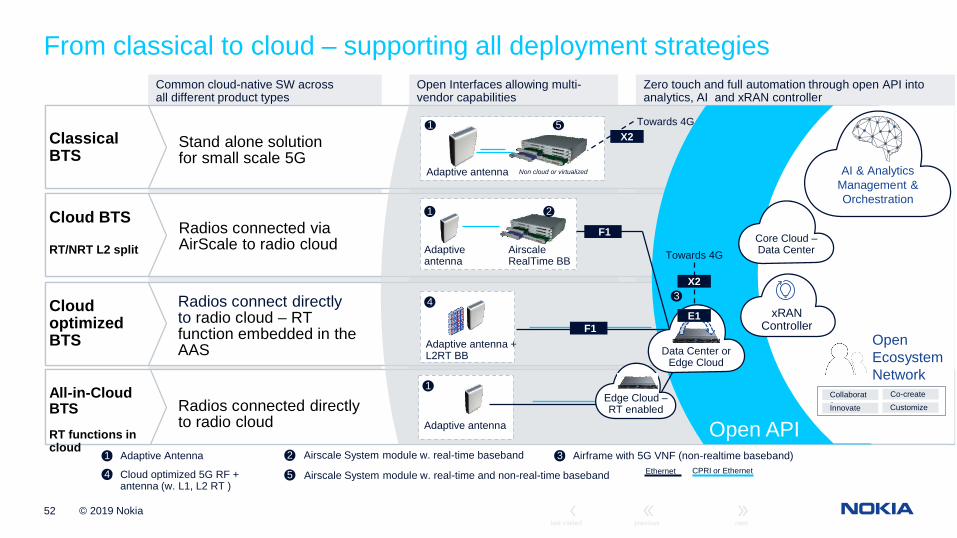
Zero touch and full automation through open API intoanalytics, AI and xRAN controller
Open Interfaces allowing multi-vendor capabilities
Common cloud-native SW acrossall different product types
From classical to cloud – supporting all deployment strategies
All-in-CloudBTSRT functions incloud
Radios connected directlyto radio cloud
Ethernet
2 31 Adaptive Antenna Airscale System module w. real-time baseband Airframe with 5G VNF (non-realtime baseband)
54 Cloud optimized 5G RF +antenna (w. L1, L2 RT )
Airscale System module w. real-time and non-real-time baseband CPRI or Ethernet
ClassicalBTS
Stand alone solutionfor small scale 5G
Radios connected viaAirScale to radio cloud
Cloud BTS
RT/NRT L2 split
CloudoptimizedBTS
Radios connect directlyto radio cloud – RTfunction embedded in theAAS
Non cloud or virtualized
1 5
Adaptive antenna
Adaptive antenna
1
Open API
AI & AnalyticsManagement &Orchestration
xRANController
OpenEcosystemNetwork
Collaborate
Co-create
Innovate Customize
Adaptiveantenna
AirscaleRealTime BB
Adaptive antenna +L2RT BB Data Center or
Edge Cloud
21
4 3
F1
F1
E1
X2
Towards 4G
X2Towards 4G
Core Cloud –Data Center
Edge Cloud –RT enabled
53
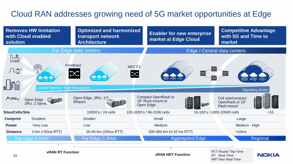
Cloud RAN addresses growing need of 5G market opportunities at Edge
RegionalAggregated EdgeFar Edge C-RANFar edge D-RAN
Edge / Central data centersFar Edge data centers
Sites/Cells/Site 10000’s / 24 cells 100-1000’s / 96-1536 cells 10-100’s / 1000-10000 cells <10
Footprint Smallest Smaller Small Large
Power Very Low Low Medium Medium - High
Signaling drivenLowest latency / high throughput
Compact OpenRack or19” Rack-mount orOpen Edge
Open Edge, 3RU, 1/3-5Racks
Full size/compactOpenRack or 19”Rack-mount
Distance 0 km (<50us RTT) 20-40 km (240us RTT) 200-350 km (4-10 ms RTT) >10ms
Open Edge2RU, 2 Server
vRAN RT Function vRAN NRT Function
Fronthaul NRT F1
RTT Round Trip-TimeRT Real TimeNRT Non Real Time
Removes HW limitationwith Cloud enabledsolution
Optimized and harmonizedtransport networkArchitecture
Competitive Advantagewith 5G and Time tomarket
Enabler for new enterprisemarket at Edge Cloud
© 2019 Nokia54 Confidential
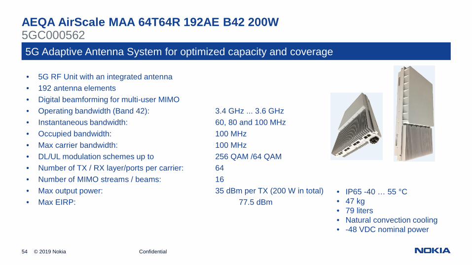
AEQA AirScale MAA 64T64R 192AE B42 200W5GC0005625G Adaptive Antenna System for optimized capacity and coverage
• 5G RF Unit with an integrated antenna• 192 antenna elements• Digital beamforming for multi-user MIMO• Operating bandwidth (Band 42): 3.4 GHz ... 3.6 GHz• Instantaneous bandwidth: 60, 80 and 100 MHz• Occupied bandwidth: 100 MHz• Max carrier bandwidth: 100 MHz• DL/UL modulation schemes up to 256 QAM /64 QAM• Number of TX / RX layer/ports per carrier: 64• Number of MIMO streams / beams: 16• Max output power: 35 dBm per TX (200 W in total)• Max EIRP: 77.5 dBm
• IP65 -40 … 55 °C• 47 kg• 79 liters• Natural convection cooling• -48 VDC nominal power

© 2019 Nokia55 Confidential
AEQD AirScale MAA 64T64R 128AE B43 200W5GC0006645G Adaptive Antenna System for optimized capacity and coverage
• 5G RF Unit with an integrated antenna• 128 element antenna• Digital beamforming for multi-user MIMO• Operating bandwidth (Band 43): 3.6 GHz ... 3.8 GHz• Instantaneous bandwidth: 60, 80 and 100 MHz• Occupied bandwidth: 100 MHz• Max carrier bandwidth: 100 MHz• DL/UL modulation schemes up to 256 QAM /64 QAM• Number of TX / RX layer/ports per carrier: 64• Number of MIMO streams / beams: 16• Max output power: 35 dBm per TX (200 W in total)• Max EIRP: 76 dBm
• IP65 -40 … 55 °C• 40 kg• 59 liters• Natural convection cooling• -48 VDC nominal power
© 2019 Nokia56 Confidential
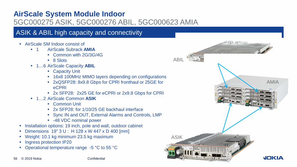
AirScale System Module Indoor
ASIK & ABIL high capacity and connectivity
ABIL
ASIK
AMIA
• AirScale SM Indoor consist of• 1 AirScale Subrack AMIA
• Common with 2G/3G/4G• 8 Slots
• 1…6 AirScale Capacity ABIL• Capacity Unit• 16x8 100MHz MIMO layers depending on configurations• 2xQSFP28: 8x9.8 Gbps for CPRI fronthaul or 25GE for
eCPRI• 2x SFP28: 2x25 GE for eCPRI or 2x9.8 Gbps for CPRI
• 1…2 AirScale Common ASIK• Common Unit• 2x SFP28: for 1/10/25 GE backhaul interface• Sync IN and OUT, External Alarms and Controls, LMP• -48 VDC nominal power
• Installation options: 19 inch, pole and wall, outdoor cabinet• Dimensions 19” 3 U : H 128 x W 447 x D 400 [mm]• Weight: 10.1 kg minimum 23.5 kg maximum• Ingress protection IP20• Operational temperature range -5 °C to 55 °C
5GC000275 ASIK, 5GC000276 ABIL, 5GC000623 AMIA

57
Thank You
Matti Keskinen – Internal Consultant
Some Extramaterial
59 © Nokia Solutions and Networks 2014
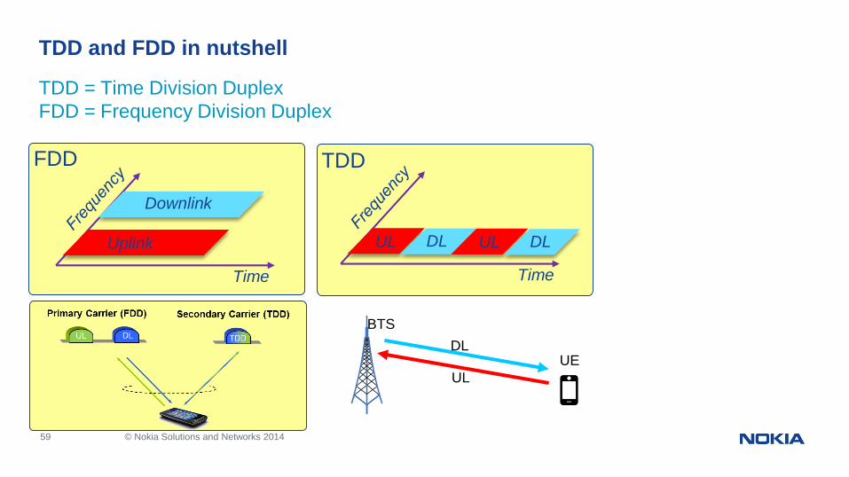
TDD = Time Division DuplexFDD = Frequency Division Duplex
TDD and FDD in nutshell
Uplink
Downlink
Time
UL DL
Time
UL DL
TDDFDD
UE
BTSDL
UL
60 © Nokia Solutions and Networks 2014
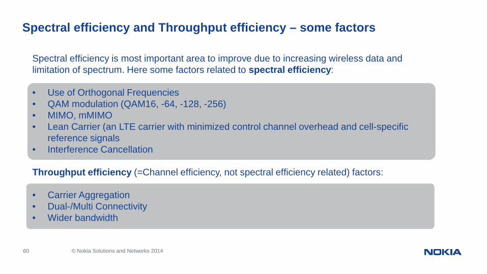
Spectral efficiency and Throughput efficiency – some factors
Spectral efficiency is most important area to improve due to increasing wireless data andlimitation of spectrum. Here some factors related to spectral efficiency:
• Use of Orthogonal Frequencies• QAM modulation (QAM16, -64, -128, -256)• MIMO, mMIMO• Lean Carrier (an LTE carrier with minimized control channel overhead and cell-specific
reference signals• Interference Cancellation
Throughput efficiency (=Channel efficiency, not spectral efficiency related) factors:
• Carrier Aggregation• Dual-/Multi Connectivity• Wider bandwidth
61 © Nokia Solutions and Networks 2014
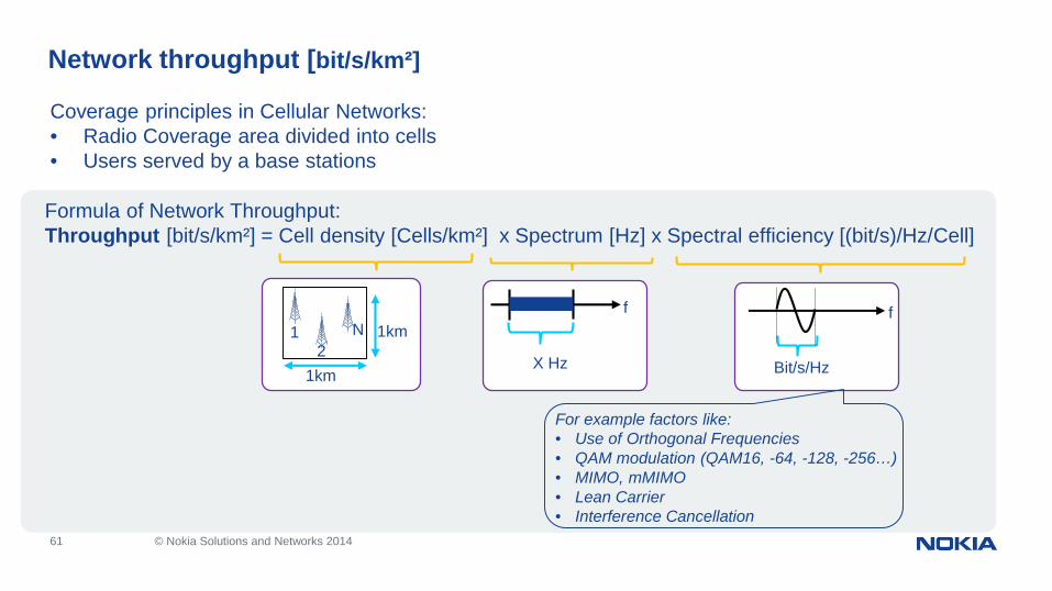
Network throughput [bit/s/km²]
Formula of Network Throughput:Throughput [bit/s/km²] = Cell density [Cells/km²] x Spectrum [Hz] x Spectral efficiency [(bit/s)/Hz/Cell]
Coverage principles in Cellular Networks:• Radio Coverage area divided into cells• Users served by a base stations
12
N 1km
1kmX Hz
f f
Bit/s/Hz
For example factors like:• Use of Orthogonal Frequencies• QAM modulation (QAM16, -64, -128, -256…)• MIMO, mMIMO• Lean Carrier• Interference Cancellation