Embed Size (px)
Citation preview

Mobile Off -Road Retrofit SCRT®
System Demonstration Program
Ray Conway and Mark Schmale Johnson Matthey
July 29, 2010

Johnson Matthey Overview Johnson Matthey Overview

• British Company - established in 1817, London.
• Incorporated as Limited Company in 1891.
• Member of the FTSE 100
Johnson Matthey Plc
• Comprised of three divisions.
• Employing 7,700 people in 38 countries.
• Sales revenue of $12 billion.
• Sole PGM marketing agent for Anglo Platinum formerly Rustenburg Platinum Mines Ltd.

Johnson Matthey Divisions
Johnson Matthey is a specialty chemicals company focused on its core skills in precious
metals, catalysts, and fine chemicals. It is organized into three global divisions:
Precious Metal Products
Fine Chemicals and Catalysts
Environmental Technologies

Johnson Matthey Precious Metal Products Division
• Platinum Marketing
• PGM Refining
• Gold & Silver Refining
• Bullion Products
• Color Technologies
• Jewelry
Sole Marketing Agent for The Largest Platinum Mines in South Africa – Anglo Platinum

Johnson Matthey Fine Chemicals & Catalysts Division
• Catalysts and Chemicals
• Pharmaceutical Materials and Services:
• Anti-cancer drugs
• C ll d b• Controlled substances
• Non-Controlled Products
• Contract R&D and Manufacturing Services
• Research Chemicals

Johnson Matthey Environmental Technologies Division
• Emission Control Technologies
• Mobile
• SSEC
• Process Catalysts & Technologies
• AMOG
• Davy Process Technology
• Fuel Cells

0 •
Global Networks
Wayne, USA
Royston, UK Sonning, UK Brussels, BELGIUM
Kitsuregawa, JAPAN
Gothenburg, SWEDEN
Delhi, INDIA
Detroit, USA
Shanghai, CHINA
Krasnoyarsk, RUSSIA
KOREA
12 Manufacturing Sites
Queretaro, MEXICO
Pilar, ARGENTINA
Germiston, RSA
Kuala Lumpur, MALAYSIA
Curitiba, BRAZIL
7 Technology Centres

Emission Control Technologies
• Comprises the autocatalyst, heavy duty diesel and stationary emissions control businesses
• Supply 35-40% of the world’s auto catalyst
• JM’s advanced NOx control technology, SCRT ®, has been listed on EPA’s Emerging Technology List: in the process of being verified by the EPA and CARB
• The AdvCCRT® and CRT® Diesel Particulate Filter are EPA verified and CARB verified
• JM CRTs installed on over 5 million LDD vehicles and 1,000,000 HDD vehicles – OE & Retrofit
• JM DOC’s installed on millions of LDD vehicles, 400,000 HDD vehicles, 12,000 urban buses, and 25,000 off-road equipment – OE & Retrofit
• JM technology supplied for US’07 and US’10 and Euro 4/5

ICAT Grant No: 06-06

GRANT OBJECTIVE
The purpose of the ICAT grant to JM was to demonstrate SCRT technology on two pieces
of off-road diesel powered machines

SCRT TECHNOLOGY
What is it?
CRT® + SCR = SCRT®
CRT® = Continuously Regenerating Technology, JM’s passively regenerating diesel PM filter technology
SCR = Selective Catalytic Reduction of NOx

Why the SCRT System?
HOT FTP Cycle - Optimized SCCRT On Cummins ISM 280 • Demonstrated on dozens of on-
road applications
Tem
pera
ture
(C
)
Pre-SCR Temp
CCRT Inlet Temp
NOx-SCCRT Optimized
NOx-OEMBaseline
Minimum Urea Injection Temperature
• Being considered for on-road verification with EPA and CARB • Proven NOx reduction
50
40
30
20
Daily NOX Reduction and Average SCR inlet temp Truck 5908 10
100 500
0 90 450
0 200 400 600 800 1000 1200 1400
400 Time (Sec) 80
70 350
Reduction
Average SCR in Temp ( C )
03/08 03/18 03/28 04/07 04/17 04/27 05/07 05/17 05/27
Time
60 300
50 250
40 200
SC
R in
lt te
mp
(°C)
150
NO
x (p
pm)
NO
x R
educ
tion
(%)
20 100
10 50
0 0
90
80
70
60
30
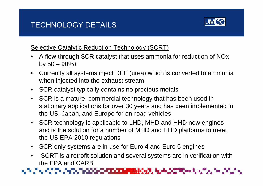
TECHNOLOGY DETAILS
Selective Catalytic Reduction Technology (SCRT) • A flow through SCR catalyst that uses ammonia for reduction of NOx
by 50 – 90%+ • Currently all systems inject DEF (urea) which is converted to ammonia
when injected into the exhaust stream • SCR catalyst typically contains no precious metals • SCR is a mature, commercial technology that has been used in
stationary applications for over 30 years and has been implemented in the US, Japan, and Europe for on-road vehicles
• SCR technology is applicable to LHD, MHD and HHD new engines and is the solution for a number of MHD and HHD platforms to meet the US EPA 2010 regulations
• SCR only systems are in use for Euro 4 and Euro 5 engines • SCRT is a retrofit solution and several systems are in verification with
the EPA and CARB

INPUT FROM ENGINE
IECU
COOLANT FROM UREA FROM TANK-... E NG I NE t """'"=-, .-=-:::U:::.R::.:EA:..:.:R=.E:::TU~. :.:..R.::N:.:., .:_..:.._-::.:~=:::::::::::--w-"'r"""'\,
AIRTAiNK COOLANT TO TAINK
RETURN1 TO ENGINE
UREA.TANK
ENGINE EXHAUST
UREA PUMP
SCR INLET TEMPERATURE SENS·OR
TECHNOLOGY DETAILS
Selective Catalytic Reduction Technology (SCRT)

TECHNOLOGY DEMONSTRATION
SCRT
Ozark / Raley’s Truck 1555 (2.5g NOx engine)
System Description
2005 Injector Vehicle Grundfos
Kenworth type
Engine 2005 CUM ISX 400 Hp
14 l Sensors
IFM Efector Kavlico
CRT
8.5 l DOC Primary Purpose
Performance evaluation/ Verification
22l 200 cpsi coated fitler
Installed Aug 2007
25.5 l Zeolite Other SCR
4.2 l ASC
11/16/2007 - 1/23/2008
NOx Reduction 80.6%
Hours run 191.3
Overall CRT P200 78.0%
Overall SCR P200 81.1%

TECHNOLOGY DEMONSTRATION
SCRT

MACHINE SELECTION FOR ICAT
Fleet Operator Los Angeles Sanitation District (Carson)
Operator Identification 8231 8239 Number
Machine Make Hyundai Caterpillar
Machine Model HL 740-7 966 GII
Model Year 2005 2003
Machine Identification Number
LF0110523 0AXJ01440
Engine Make Cummins Caterpillar
Engine Model ISC 3176C
Engine Displacement 8.3 L 10.3 L
Engine Emissions Family 5CEXL0359AAD 3CPXL10.3ESK
Engine Power 140 HP 327 HP

MACHINE SELECTION
Hyundai HL740-7
Caterpillar 966 GII

SCRT SYSTEM DESIGN
Component Hyundai Caterpillar
DOC 1 - 10.5x6 1 – 11.25x5
Catalyst Components
DOC 1 10.5x6 DOC
1 11.25x5 DOC
DPF 1 – 10.5x12 CSF
1 – 12x12 Bare DPF
SCR 2 – 10.5x6 Fe Zeolite
2 – 12x6 Fe Zeolite
Slip Catalyst 1 – 10.5x3 1 – 12x4

SCRT SYSTEM DESIGN
Dosing Pump Grundfos Air Assisted Dosing Components Dosing
Grundfos Nozzle
Custom ECU by STT Emtec with JM Controller proprietary Dosing and Diagnostic
Algorithm
EO NOx Sensor (feed forward t l)
Sensors
control)
TP NOx Sensor (Datalogging, NOx Reduction Monitoring)
Exhaust Backpressure
Nozzle Line pressure
CRT Temperature (inlet)
SCR Temperature (inlet)
Urea Tank Custom Stainless Steel
Air System Ready Air AAA 12V electric compressor with 6 gal air tank reservoir

SCRT System Integration Design Factors
Factors Contributing to Design: • Minimize Engine Turbo-to-Exhaust
system Distance • Proximity to Structural mounting points • Proximity to Structural mounting points
on the machine • Availability of 12V power • Availability of Compressed Air

Design Solution – Hyundai HL 740-7
• Distance – Good – DPF mounted within 48 inches of the turbo outlet
• Proximity to Structural mounting – Good – Engine shroud made of structural members sufficient
to support CCRT and SCR modules
• AAvailability il bilit off 12V12V PPower • – Ok – Machine operates on 24V, but uses two 12V batteries
in series, so power was connected between ground and 12V terminal
• Compressed Air Availability – NO! – Procured a mobile air compressor system with a
reservoir tank

Design Solution – Hyundai HL 740-7
• CCRT® filter mounted in Engine compartment • SCR mounted on top of the engine compartment • DEF Tank and • DEF Tank and Dosing System mounted adjacent to cab on Wheel Fender
SCR
DEF
Dosing Pump
CCRT
DEF Tank Air
Tank

Design Solution – CAT 966 GII
• Distance – Excellent – DPF mounted within 15 inches of the turbo outlet
• Proximity to Structural mounting – OK – Engine shroud NOT made of structural members.
Special mounting had to be designed to Engine Block/Head
• AAvailability il bilit off 12V12V PPower • – Ok – Machine operates on 24V, but uses two 12V batteries
in series, so power was connected between ground and 12V terminal
• Compressed Air Availability – NO! – Procured a mobile air compressor system with a
reservoir tank

Design Solution – Caterpillar 966 GII
• CRT® filter and SCR mounted in Engine compartment • DEF Tank and Dosing System mounted adjacent mounted adjacent to cab on Wheel Fender • Air Tank and Reservoir mounted adjacent to Operator Entry on Railing
CRT
SCR
Dosing Pump
Air Tank
DEF Tank

System Installation
• DPF installed on October 30, 2008 • SCR installed on August 14, 2009 • Hyundai Unit operated satisfactorily
upon installationupon installation • CAT Unit was not able to communicate
with the SAE J1939 network with the engine
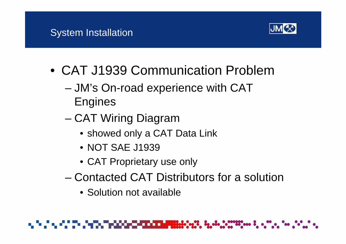
System Installation
• CAT J1939 Communication Problem – JM’s On-road experience with CAT
Engines – CAT Wiring Diagramg g
• showed only a CAT Data Link • NOT SAE J1939 • CAT Proprietary use only
– Contacted CAT Distributors for a solution • Solution not available

System Installation – Hyundai HL 740-7
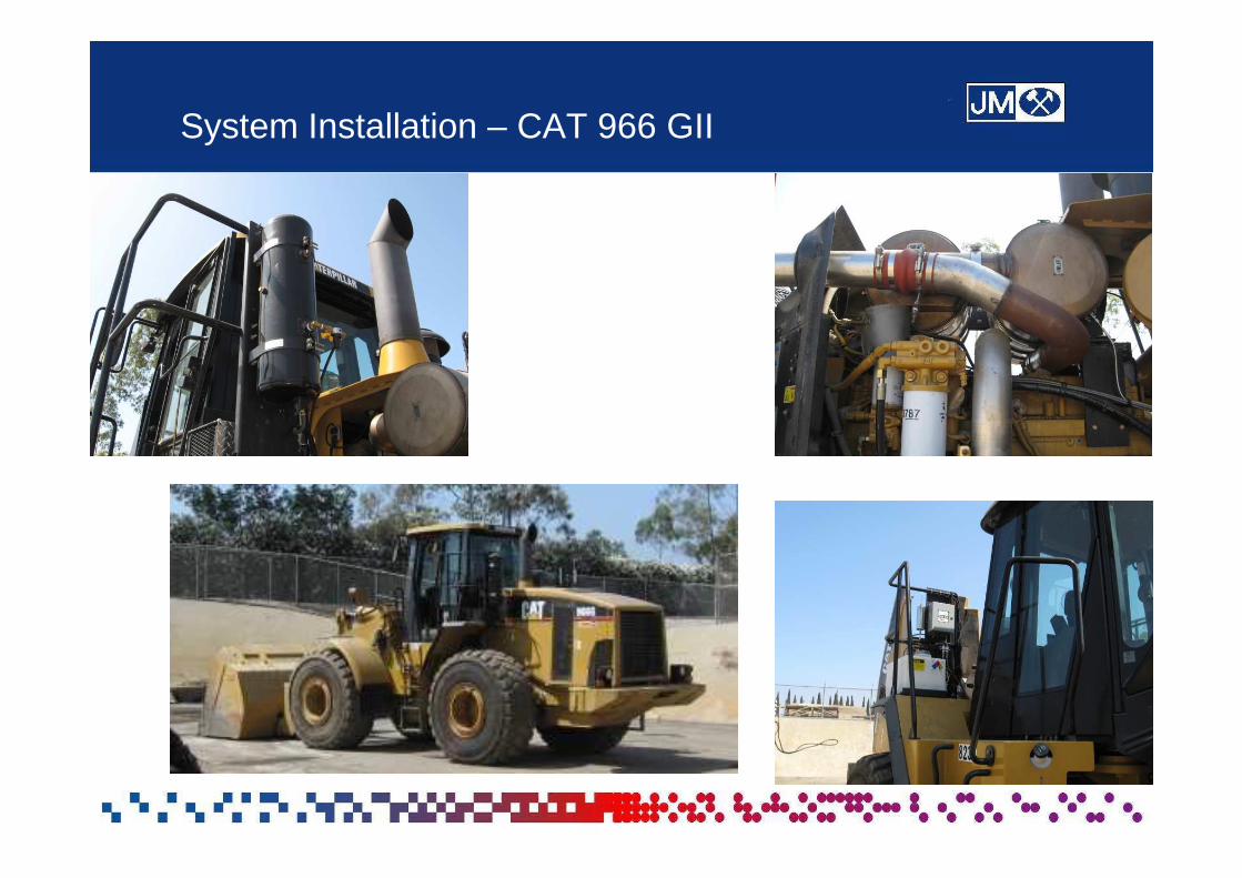
System Installation – CAT 966 GII

System Performance – Phase I
ICAT, LASD, Hyundai Front-EndLoader May 21, 2009
3Hyundai Unit • Backpressure stable
2.5
• 93.5 hours of operation over 6 2
1.5 months
Pre
s, in
-Hg
Max Pres
0
0.5
1
09/09/08 10/29/08 12/18/08 02/06/09 03/28/09 05/17/09 07/06/09
Date
• CCRT filter was operating properly
I-

I I/ \ I'--I I
\ I \ /\ \ I \I -
I \ I
V I
/ \ I
/
-
\
System Performance – Phase I
ICAT, LASD, Caterpillar FEL 5/21/2009 Download
5Caterpillar Unit • Backpressure
4.5
4
stable 3.5
• 43.5 hours of 3
2.5
Pea
k B
aack
pres
sure
, in
-Hg
operation over 6operation over 6 months
• Indicates CRT filter was operating properly
9/9/2008 0:00 10/29/2008 0:00 12/18/2008 0:00 2/6/2009 0:00 3/28/2009 0:00 5/17/2009 0:00 7/6/2009 0:00
2
1.5
1
0.5
0
Date/Time

• ■
•
♦
♦ ... ♦
♦
•■ ■ ■
■ ■ ■
■ ♦ -- ■
■ ■ ■
~ ~ ~ ~ - - - - - -
System Performance – Phase II
Hyundai Unit 100
ICAT, Hyundai FEL Daily Summary Data
90
Daily Reduction (%, mass) Peak Back Pressure (inHg)
9• Backpressure 80 8stable 70 7• 9 hours of 60 operation
Per
cent
Red
uctio
n, %• CCRT filter was
operating
0
1
2
3
4
5
0
10
20
30
40
50
08/05 08/15 08/25 09/04 09/14 09/24 10/04 10/14
properly • Average NOx Reduction = 74%
Date
Bac
kPre
ssur
e, i
nn-H
g
10
6

ICAT, LASD, Hyundai FEL
NOx Reduction vs. Dosing Temperature 100
90
80
70
* 60 ~
._g u :::, '.JO "Cl <U r::: X 0 z 40
30
20
10
// // .
// //
//
,,,,/ • / ~ /
♦
• /r
\ ♦ ///
r/
// \
// Averaee
//
/ //
,,,/ /♦
/ ,/
//
,,,,,,,,,,,,,,,//
v/ ()
0 10 20 30 40 50 60 70 80 90 100
E)(haust Gas Temperature, % Time above Dosing Temperature
System Performance – Phase II
NOx Reduction depends on amount of time system is dosing

Cl ~ .5 ai :i (J) (J) Ql ... =.. ~ -.i (ti
m .:ii: (ti Ql
CL
7
6
5
4
3
2
1
0 ---
ICAT, LASO, Caterpillar FEL 10/2112009 Down load
. .L ,_
8/15/09 8/25/09 9/4/09 9/14/09 9/24/09 -10/4/09 10/'14/09 10/24/09 -1 -1 /3/09 DaTe/Time
System Performance – Phase II
Caterpillar Unit • Backpressure stable • 32 hours of operation • CRT filter was operating properly

Project Issues
Hyundai Unit • October 2009 – LASD Arranged Service for
non-SCRT related issue • After service, SCRT system stopped
operatinggp • JM discovered issue during January 2010
inspection • Investigation revealed the system was re-
wired to 24V system • Caused over-voltage to critical components of
SCRT system. System malfunctioned and stopped operating.

Project Issues
Caterpillar Unit • No SAE J1939 Datalink found on machine
during system installation
• Contacted CAT Distribution network • Contacted CAT Distribution network
• After investigating, CAT distributors were not able to identify a solution for communication

Project Issues
Operator Worksite Visibility • Not identified as a requirement at beginning of project • Became apparent during discussions with
Distributors knowledgeable with off-road markets • Will need to understand requirements prior to
integrating technology on future projects • Cal/OSHA looking to revise Title 8 language for
safety/visibility • May limit available space for mounting components
on machine chassis

Summary
• CRT and CCRT Diesel Particulate Filter systems operated well on the chosen off-road applications
• The SCRT system demonstrated > 70% NOx Reduction on the Hyundai machine
• Effective design of SCRT system enabled retrofit installation within a tight packaging envelope
• TheThe SCRTSCRT sysystemem on the Caterpillar machine waswas notnot • st on the Caterpillar machine operational due to the lack of the J1939 datalink
• SAE J1939 datalinks may not always be available on off-road machinery
• Emissions control equipment should be designed to accommodate a wide range of operating voltages found on off-road equipment
• An on-board compressed air option should be made available for off-road equipment

• Questions??