Embed Size (px)
Citation preview
t'""
\,,,-_
RULES FOR CLASSIFICATION OF
MOBILE OFFSHORE UNITS
MATERIALS AND WELDING
PART 2 CHAPTER 1
STEEL AND IRON
SEPTEMBER 1982
SECTIONS PAGE
General Requirements ......................... , .............. .
2 Rolled Steel for Structural Applications. . . . . . . . . . . . . . . . . . . . . . . . . . . 8
3 Rolled Steel for Boilers, Pressure Vessels and Special Applications . . . . . 15
4 Clad Steel Plates . . . . . . . . . . . . . . . . . . . . . . . . . . . . . . . . . . . . . . . . . . . . . 23
5 Steel Tubes and Pipes. . . . . . . . . . . . . . . . . . . . . . . . . . . . . . . . . . . . . . . . . 25
6 Forgings. . . . . . . . . . . . . . . . . . . . . . . . . . . . . . . . . . . . . . . . . . . . . . . . . . . . 32
7 Bars for Chain Cables. . . . . . . . . . . . . . . . . . . . . . . . . . . . . . . . . . . . . . . . . 41
8 Steel Castings . . . . . . . . . . . . . . . . . . . . . . . . . . . . . . . . . . . . . . . . . . . . . . . 43
9 Iron Castings. . . . . . . . . . . . . . . . . . . . . . . . . . . . . . . . . . . . . . . . . . . . . . . . 49
DETNORSKE VERITAS VERITASVEIEN l, 1322 H0VIK, NORWAY
IJ-ll TELEPHONES: + 47 2 12 99 00 TELEX: 76192
CHANGES IN THE RULES
9 General.
The present edition of the Rules includes additions and amendments decided by the Board as of l st of September l 982 and supersedes relevant chapters/ sections of the l 98 l edition of the complete Rules.
This chapter is valid until superseded by a revised chapter. Supplements will not be issued except for an updated list of corrections presented in the introduction booklet. The introduction booklet is nOrmally revised in January and July each year.
Revised chapters will be forwarded to all subscribers to the Rules. Buyers of reprints are advised to check the updated list of Rule chapters printed on the front page of the introduction booklet to ensure that the chapter is current.
9 Part 2 Chapter I
This chapter was not included in the l 98 l edition of the Rules. It is the corresponding chapter in the current Rules for Classification of Steel Ships, to which reference were given in the l 98 l edition of the Rules for Classification of Mobile Offshore Units.
The major changes to this chapter with reference to the corresponding chapter in the current Rules for Classification of Steel Ships are:
Sec. I
Requirements regarding approval of manufacturers of steel castings with special toughness properties have been included.
Requirements regarding approval of welding procedures and welders in connection with repair welding have been included.
Sec. 2
- New rules for extra high strength steel have been.included. - Additional requirements for steel with improved through thickness properties have been included.
Sec, 8
- New rules for steel castings with special toughness properties have been included.
© Det norske Veritas 1982 Printed in Norway by Det norske Veritas
9.82.1500 8.83.1000
c:

('.--.
<-_
CONTENTS
SEC. 1 GENERAL REQUIREMENTS.
A. Classification ................................ . A I 00 Application. A 200 Approval of manufacturers. A 300 Production material testing.
B. Definitions ......................... · . . . . . . . . . . 2 B I 00 Test samples and specimens. B 200 Certificates.
C. Testing ..... , . . . . . . . . . . . . . . . . . . . . . . . . . . . . . . . . 2 C I 00 General. C 200 Test samples. C 300 Preparation of specimens. C 400 Tensile testing at ambient temperatures. C 500 Bend testing. C 600 Impact testing. C 700 Drop-weight testing. C 800 Z-direction ductility testing. C 900 Determination of grain size. C 1000 Other testing
D. Documentation and Branding . . . . . . . . . . . . . . . . . . . 6 D I 00 Certification by the Society. D 200 Declaration by the manufacturer.
SEC. 2 ROLLED STEEL FOR STRUCTURAL APPLICATION.
A. General . . . . . . . . . . . . . . . . . . . . . . . . . . . . . . . . . . . . . 8 A 100 Scope.
B. Normal Strength Steel ........................ . B I 00 Steel grades. B 200 Chemical composition. B 300 Mechanical properties. B 400 Heat treatment.
8
C. High Strength Steel . . . . .. . . . .. . . . . .. . . . . . . .. . . I 0 C I 00 Steel grades. C 200 Chemical composition. C 300 Mechanical properties. C 400 Heat treatment.
D. Extra High Strength Steel . . . . . . . . . . . . . . . . . . . . . . 11 D 100 Steel grades. D 200 Manufacture. D 300 Chemical composition. D 400 Mechanical properties.
E. Testing . . . . . . . . . . . . . . . . . . . . . . . . . . . . . . . . . . . . . . 12 E I 00 Samples for testing. E 200 Tensile testing. E 300 Impact testing. E 400 Re-testing. E 500 Testing of through thickness properties. E 600 Inspection - tolerances.
F. Repair of Defects .. .. .. .. .. .. .. .. .. .. .. .. .. .. . 14 F I 00 Surface defects.
SEC. 3 ROLLED STEEL FOR BOILERS. PRESSURE VESSELS AND SPECIAL APPLICATIONS.
A. General . . . . . . . . . . . . . . . . . . . . . . . . . . . . . . . . . . . . 15 A 100 Scope.
B. Carbon and Carbon Manganese Steel . . . . . . . . . . . . . 15 B I 00 Steel grades. B 200 Chemical composition.
B 300 Mechanical properties. B 400 Heat treatment.
C. Alloy Steel . . . . . . . . . . . . . . . . . . . . . . . . . . . . . . . . . . . 15 C I 00 Steel grades. C 200 Chemical composition. C 300 Mechanical properties. C 400 Heat treatment.
D. Testing ....................................... 20 D I 00 Tensile testing. D 200 Impact testing. D 300 Drop weight testing. D 400 Bend testing. D 500 Inspection - tolerances.
E. Identification of Materials . . . . . . . . . . . . . . . . . . . . . . 21 E I 00 Branding.
SEC. 4 CLAD STEEL PLATES.
A. General . . . . . . . . . . . . . . . . . . . . . . . . . . . . . . . . . . . . . 23 A JOO Scope. A 200 Heat treatment.
B. Base Material . . . . . . . . . . . . . . . . . . . . . . . . . . . . . . . . 23 B 1 00 General.
C. Cladding Metal . . . . . . . . . . . . . . . . . . . . . . . . . . . . . . . 23 C 1 00 General. C 200 Chemical composition.
D. Testing . . . . . . . . . . . . . . . . . . . . . . . . . . . . . . . . . . . . . . 23 D I 00 General. D 200 Tensile testing. D 300 Impact testing. D 400 Bend testing. D 500 Shear testing. D 600 Ultrasonic testing. D 700 Corrosion testing. D 800 Inspection - tolerances.
E. Repair and Reje•tion E I 00 Surface defects. E 200 Rejection.
.......................... 24
F. Identification of Materials . . . . . . . . . . . . . . . . . . . . . . 24 F I 00 Branding.
SEC. 5 STEEL TUBES AND PIPES.
A. General . . . . . . . . . . . . . . . . . . . . . . . . . . . . . . . . . . . . . 25 A 100 Scope. A 200 Steel grades. A 300 Manufacture. A 400 Chemical composition. A 500 Mechanical properties. A 600 Heat treatment.
B. Testing . . . . . . . . . . . . . . . . . . . . . . . . . . . . . . . . . . . . . . 28 B I 00 Test classes. B 200 Tensile test. B 300 Flanging test. B 400 Ring tests. B 500 Impact test. B 600 Inspection - tolerances. B 700 Hydraulic pressure testing. B 800 Non-destructive testing. B 900 Corrosion testing. B I 000 Re-testing.

SEC. 6 FORGINGS.
A. General ..................................... 32 A 100 Scope. A 200 Manufacture. A 300 Chemical composition. A 400 Mechanical properties. A 500 Heat treatment.
B. Testing . . . . . . . . . . . . . . . . . . . . . . . . . . . . . . . . . . . . . . 36 B 1 00 General. B 200 Samples for testing. B 300 Hardness testing. B 400 Ultrasonic testing. B 500 Magnetic particle testing. B 600 Sulphur print testing.
C. Welding and Weld Repairs . . . . . . . . . . . . . . . . . . . . . 40 C 1 00 Welding. C 200 Repair of defects by welding. C 300 Repair welding after damages.
SEC. 7 BARS FOR CHAIN CABLES.
A. General . . . .. . . . . . . . . . . . . . . . . . . . . . . . . . . . . . . . . 41 A 100 Scope. A 200 Steel grades. A 300 Chemical composition. A 400 Mechanical properties. A 500 Heat treatment.
B. Testing . . . . . . . . . . . . . . . . . . . . . . . . . . . . . . . . . . . . . . 41 B 100 Number of tests. B 200 Impact testing.
C. Identification of Materials . . . . . . . . . . . . . . . . . . . . . . 41 C 1 00 Branding.
SEC. 8 STEEL CASTINGS.
E. Chain Cable Castings . . . . . . . . . . . . . . . . . . . . . . . . . . 44 E 100 Specification.
F. Castings for Structural Members with Higher Toughness Requirements . . . . . . . . . . . . . . . . . . . . . . . . . . . . . . . . . 44
F 100 Steel grades. F 200 Chemical composition. F 300 Mechanical properties.
G. Steel Castings fOr Design Temperatures below - 10°C and fOr Liquified Gas Systems . . . . . . . . . . . . . . . . . . 45
G 100 Chemical composition. G 200 Mechanical properties. G 300 Permissible design temperature.
H. Heat Treatment ............................... 45 H 100 General. H 200 Heat treatment of carbon and carbon-manganese ste
el. H 300 H 400
Heat treatment of low alloyed steel. Heat treatment of stainless steel.
I. Testing . . . . . . . . . . . . . . . . . . . . . . . . . . . . . . . . . . . . . . 46 I 100 Test samples. I 200 Mechanical tests. I 300 Hydraulic pressure testing. I 400 Visual and non-destructive examination.
J. Rectification of Defective Castings ............ 48 J 100 Repair welding.
K. Welding of structural Members .................. 48 K 1 00 Welding regulations.
SEC. 9 IRON CASTINGS.
A. General ..... A 100 Scope.
. ............................ 49
A. General ............................... . 43 B. Nodular Cast Iron ............................. 49 A 100 Scope.
B. Castings for General Application ................ 43 B 1 00 Steel grades. B 200 Chemical composition. B 300 Mechanical properties.
C. Castings for Boilers and Pressure Vessel .......... 44 C 100 Steel grades. C 200 Chemical composition. C 300 Mechanical properties.
D. Propeller Steel Castings . . . . . . . . . . . . . . . . . . . . . . . . 44 D 100 Chemical composition. D 200 Mechanical properties.
B 100 Chemical composition. B 200 Mechanical properties.
C. Grey Cast Iron ............................... 49 C 100 Specification. C 200 Chemical composition. C 300 Mechanical properties.
D. Testing . . . . . . . . . . . . . . . . . . . . . . . . . . . . . . . . . . . . . . 49 D 100 Samples for testing. D 200 Photo-micrographs. D 300 Tensile testing.
E. Repair of Defects E 1 00 General.
........................ 49
I..:_-:··:
(
~----
Mobile Offshore Units Pt.2 Ch.I Sec.I
SECTION 1 GENERAL REQUIREMENTS
Contents.
A. Classification. A 100 Application. A 200 Approval of manufacturers. A 300 Production material testing.
B. Definitions. B 100 Test samples and specimens. B 200 Certificates.
C. Testing. C 1 00" General. C 200 Test samples. C 300 Preparation of specimens. C 400 Tensile testing at ambient temperature. C 500 Bend testing. C 600 Impact testing. C 700 Drop-weight testing. C 800 Z-direction ductility testing. C 900 Determination of grain size. C 1000 Other testing.
D. Documentation and Branding. D 100 Certification by the Society. D 200 Declaration by the manufacturer.
A. Classification.
A 100 Application.
lOI The Rules in this Chapter apply to rolled, forged and cast steels and iron casting required in structures, equipment, boiler and pressure vessels and machinery for vessels classified or intended for classification with the Society. Materials complying with recognized standards with specifications equivalent to the requirements of this chapter may be accepted.
102 Grades of material with properties other than specified in this Chapter may be accepted after special consideration.
A 200 Approval of manufacturers.
20I Approval of manufacturers with respect to the materials and grades covered by this Chapter will be considered on the basis of a detailed description of the manufacturing process and inspection routines, results from an approval testing of material from the current production, and a report made by the Surveyor confirming the information given by the works and the results.
Note: A detailed program for the approval testing ca1,1 be obtained by application to the local Surveyor of the Society.
202 Manufacturers of the following products are to be approved:
Rolled steel for structural application. Approval is required for each grade. Additional approval is required for plates made from hot rolled strips (coils) and for plates and sections produced by a controlled rolling procedure in lieu of normalizing. Additional approval is also required for steel with improved through thickness properties (Z-steeO. Rolled steel for boilers and pressure vessels and for low temperature application (see note). Welded sections for general structural application. Clad steel plates. Steel tubes. Approval is required for each grade. Ad-
ditional 3.pproval is required for each manufacturing process (e.g. seamless, electric fusion welding and butt welding) and for each of the following special applications:. chemicals, low. temperatures). Forgings. Additional approval is required for each grade of bars for forged chain cables and for crank shafts with continuous grain flow and reduced scantlings. Rolled materials intended for forgings and chain cables. Steel and iron castings. Manufacturers of steel castings for structural members 'with higher requirements to toughness are to be approved for each separate steel grade and type of component.
Note: - Manufacturers approved for delivery of hull steel grades with tensile
strength 400 - 490 NI mm2, incl. grades A. B, D and E are also ap· proved for delivery of boiler and pressure vessels steel grades 0,1 and 2 in the groups NV!, NV2 and NV3. Manufacturers approved for delivery of steel grades A, D and E in the groups NV·32 or NV-36 are also approved for delivery of boiler and pres.5ure vessel steel grades 0,1 and 2 in the groups NV4. NV5 and NV6.
203 The steel is to be made by basic oxygen, electric furnace or open hearth process or by other processes approved by the Society.
204 The reduction ratio of thickness from continiously cast slab to plate is to be minimum 5 to 1 unless otherwise approved by the Society.
205 For certain components the proposed method of manufacture may require special approval by the Society.
206 The Surveyor is to be given the opportunity to inspect and check at any time all plants and production equipment used in the manufacture and testing of materials. The manufacturer is to assist the Surveyor to enable him to verify that approved processes are adhered to and to witness the selection and testing as required by the Rules.
207 The manufacturer is to have a system for the identification of semi-finished products and castings, making it possible for the Surveyor to trace the material to its original cast.
208 When a manufacturer has more than one works, the approval is only valid for the works which carried out the test program.
209 When the manufacture of rolled products/ tubes are based on semiproducts from other works, the steel work as well as the rolling mill/ tube manufacturer are subject to approval.
210 Any approval may be withdrawn if the conditions presupposed when the approval was given, no longer are fulfilled.
A 300 Production material testing.
30I Certification of products are based on a production material testing where chemical composition, niechanical properties and other specified requirements are checked to verify compliance with the Rules or an approved specification.
302 Production material testing is normally to be carried out under supervision. of the Society according to the procedure described in D 100 and a test certificate (Det norske Veritas" certificate) as defined in B 201 is to be issued.
Issuing of the Society's certificate may also be based on

Mobile Offshore Units Pt.2 Ch.I Sec.I
rolitines and regulations other than those described in D I 00. Details about routines and regulations are then to be agreed between the Society and the manufacturer.
303 For certain products and/ or applications, the documentation of the testing, may be done by the manufacturer. In other parts of the Rules it is stated when documentation by the manufacturer may be accepted and which type of documentation according to definitions in B 200 is acceptable. The procedure to be followed by the manufacturer is described in D 200.
304 The material is to be reasonably free from segregations and non-metallic inclusions. The finished material is to be free from internal and surface defects detrimental to the intended application. Products are not to be painted and spattled before the inspection has been completed.
305 Repair of defects by welding or other methods is to be approved by the Surveyor prior to start of repair work. The Surveyor may require additional tests and nondestructive inspection of the material. Procedure qualification test as well as operater qualification test for the welders are normally required.
306 Material proving unsatisfactory during manufacture or after being built into structures, machinery or boilers may be rejected, notwithstanding any previous acceptance or certification. Retest of other material from the same cast may be requested.
B. Definitions.
B 100 Test samples and specimens.
10 I A test sample is that part of the material which is selected for testing, e.g. a rolled product or a part of it, a cast coupon or a part cut from a forging or casting.
102 A test specimen is that part of the test sample which in prepared or unprepared form is used for carrying out the testing.
B 200 Certificates.
201 Del norske Veritas' certificate (Test certificate),
A document signed by a Surveyor of the Society which contains the results of all the required tests and certifies that the tests have been carried out by the manufacturer in the presence of the Surveyor according to the Rules or according to special agreement on samples taken from the delivered products themselves.
202 Works' certificate'
A document made out by the manufacturer which contains the results of all the required tests and certifies that the tests have been carried out by the manufacturer on samples taken from the delivered products themselves.
203 Test report'
A document made out by the manufacturer which contains the results of control tests on current production, carried out on products having the same method of manufacture as the consignment, but not necessarily from the delivered products themselves.
C. Testing.
C 100 General.
101 All tests are to be carried out by competent personnel on machines of approved type. The machines are to
2
be maintained in satisfactory and accurate condition and are to be checked and calibrated, preferably in the presence of the Surveyor and the results are to be approved by him. This is to be done at suitable intervals upon agreement with the Society. A record of such checking and calibration is to be kept available in the test laboratory.
C 200 Test samples.
201 Test samples are to be selected by the Surveyor unless otherwise agreed.
202 Test samples from which test specimen are cut, are to have undergone the same heat treatment as the material from which they have been taken.
203 If test samples are cut from material by flame cutting or shearing, a reasonable margin is required to enable sufficient material to be removed from the cut edges during final machining.
204 All materials in a batch presented for testing are to be of the same product form (e.g. plates, sections, bars). Normally, the materials are to be from the same cast and in the same condition of heat treatment.
C 300 Preparation of specimens.
301 Test specimens are to be cut and prepared in a manner which does not affect their properties, i.e. not subjected to any significant cold straining or heating.
302 Where possible, test specimens from rolled materials are to retain their rolled surface on both sides.
C 400 Tensile testing at ambient temperature.
40 I Symbols related to tensile testing.
Rm = tensile strength. R, = yield stress (yield pointl. RP = yield strength (proof stressl. R1 = yield strength (proof stress), total elongation. A = percentage elongation after fracture. Z = percentage reduction of area.
402 Upper yield stress (R,H) is the highest value of stress measured at the commellcement of plastic deformation at yield; often this value is represented by a pronounced peak stress. The test is to be carried out with an elastic stress rate not exceeding 30 N/mm2 per sec.
403 When no well-defined yield phenomena exists, either the yield strength at 0 ,2 % non-proportional elongation (Rp0.,l or the yield strength at 0 ,5 % total elongation (Rt0.sl is to be determined according to the applicable specification. The test is to be carried out with an elastic stress rate not exceeding 30 NI mm2 per sec.
404 For determination of tensile strength (R,,) of ductile materials, the speed of the testing machine during the tensile test is not to exceed that corresponding to a strain-rate at maximum load of 40 % I min. For brittle materials, like cast iron the elastic stress rate is not to exceed 2 ,5 NI mm2
per sec.
405 The elongation generally means elongation determined on a proportional gauge length 5,65 vs;;; or 5d and has the designation A5.
If the material is a ferritic steel of low or medium strength and not cold worked, the elongation may also be measured on a non-proportional gauge length L0after agreement with the Society. In that case the required elongation A,,is calculated from the following formula'
- (-8)"·'° A0 - 2 As L 0
?~
As = the required elongation in 96 for test specimen with gauge length 5 ,65 y'Sa.
S0 = the cross-sectional area of the test specimen in question.
L0 = the gauge length in question.
The elongation value is valid if the fracture occurs at least the following distance from the end marks of the gauge length:
Round test specimen: Flat test specimen:
l,25d b + a
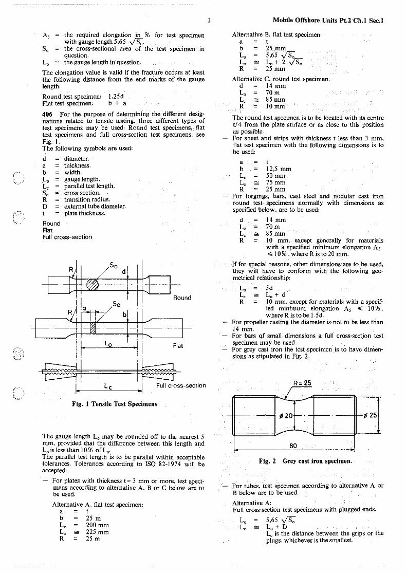
406 For the purpose of determining the different designations related to tensile testing, three different types of test specimens may be used: Round test specimens, flat test specimens and full cross-section test specimens, see Fig. I. The following symbols are used:
d = diameter. a = thickness. b = width. L 0 = gauge length. L, = parallel test length. S0 = cross-section. R = transition radius. D = external tube diameter. t = plate thickness.
Round Flat Full cross-section
So d
i I So i . Round
~a / ·1 += GFlf-ll~-t--11· Lo ·11 Flat
-E?SI . ~ I , L c • ! Full cross-section
Fig. 1 Tensile Test Specimens
The gauge length L, may be rounded off to the nearest 5 mm. provided that the difference between this length and L0 is less than l 0 % ofL0 .
The parallel test length is to be parallel within acceptable tolerances. Tolerances according to ISO 82-1974 will be accepted.
For plates with thickness t= 3 mm or more, test specimens according to alternative A, B or C below are to be used.
Alternative A, flat test specimen: a = t b = 25 m L0 = 200 mm L, "' 225 mm R = 25 m
3 Mobile Offshore Units Pt.2 Ch.1 Sec.1
Alternative B. flat test specimen: a = t b = 25 mm L0 = 5.65 y'Sa L, "'L0 +2~ R = 25 mm
Alternative C, round test specimen: d = 14 mm L0 = 70 m L, ;;,, 85 mm R = lOmm
The round test specimen is to be located with its centre t/ 4 from the plate surface or as close to this position as possible. For sheet and strips with thickness t less than 3 mm, flat test specimen with the following dimensions is to be used:
a = t b = 12,5 mm L0 = 50 mm L, ;;,, 75 mm R = 25 mm
For forgings, bars, cast steel and nodular cast iron round test specimens normally with dimensions as specified below, are to be used:
d = 14 mm L 0 = 70 m L, ;;,, 85 mm R = l 0 mm, except generally for materials
with a specified minimum elongation As ..;; 10%, where R is to20 mm.
If for special reasons, other dimensions are to be used, they will have to conform with the following geometrical relationship:
L0 = 5d Le=:= L0 +d R = l 0 mm, except for materials with a specif-
ied minimum elongation A5 ..;; l 0 % , where Risto be l .5d.
For propeller casting the diameter is· not to be less than 14 mm. For bars Qf small dimensions a full cross-section test specimen may be used. For grey cast iron the test specimen is to have dimensions as stipulated in Fig. 2.
R= 25 r--
I
¢20 -· ¢ 25
-80
Fig. 2 Grey cast iron specimen.
For tubes, test specimen according to alternative A or B below are to be used.
Alternative A: Full cross-section test specimens with plugged ends.
L0 = 5,65 VS: Le:;::::: L0 +D
L, is the distance between the grips or the plugs, whichever is the smallest.

Mobile Offshore Units Pt.2 Ch.I Sec.I
Alternative 8' Strip
a = wall thickness of the tube b = 12 mm Lo = 5,65 vs;; L, "' L0 + 2 b
C 500 Bend testing.
501 Flat bend test specimen as given in Fig. 3 is to be used. Edges on tension side to be rounded to a radius of I to 2 mm.
~ - 1· b ·1 0_,_____,_j 1.-110 ~.,~
C~ 9a+D)
Fig. 3 Bend Test Specimen.
502 For plates, structural sections and sheets-... Jest specimen with the following dimensions is to be used:
a = as rolled thickness t of material b = 30 mm
If the as rolled thickness t is greater than 25 mm, it may be reduced to 25 mm by machining on the compression side of the bend test specimen.
503 For forgings, castings and semi-finished products, test specimen with the following dimensions is to be used:
a = 20 mm b = 25 mm
C 600 Impact testing.
601 Impact testing is to be carried out as Charpy V-notch or U-notch test according to the specification in question.Each value for absorbed energy is to be determined as the average of one set of 3 impact specimens.
602 The Charpy V-notch impact toughness is the absorbed energy, expressed in Joule IJJ, the symbol being KV. The Charpy impact toughness found by test specimens with U-notches (or the keyhole tests) is the energy absorption in Joule IJJ, the symbol being KU.
603 The Charpy impact test machine is to be of a type acceptable to the Society having a gap of 40 mm, a striking velocity between 4,5 and 7 m/sec. and a striking energy of 290 ± I OJ for a standard test. The angle between the striking edges of the pendulum is to be 30° with the edge rounded to a radius 2 to 2,5 mm. (Pendulum accord, ing to ASTM E 23 will also be accepted.) The point of impact of the hammer is to be in the centre line of the notch. The scale of the machine is to be calibrated to an accuracy of + 0,5 % of the machine's maximum striking energy. Impact test machines with a striking energy of less than 290J are acceptable. In such cases, KV, or for keyhole tests, KU, is to be supplemented with an index giving the striking energy. For example, KV 145 indicates that a striking energy of 14 SJ has been used.
604 Dimensions and tolerances for Charpy V-notch and U-notch test pieces are to comply with the specifications given in 605 and 607, respectively. The test samples may be flame-cut but the notch is not to
4
be nearer to a flame-cut edge than 25 mm. The prescribed dimensions are to be accurately and systematically checked. The notch is to be made in a single cut by a special milling cutter. The cutter is always to be kept sharp so that the shape of the notch is correct and cold working at the base is avoided as far as possible. The cutter is nOt to be used for more than l 00 test specimens between each checking. There are to be no indications, scratches or marks left in the base of the notch after machining. The plane of symmetry of the notch is to be at right angle to the longitudinal axis of the test specimen.
605 Dimensions and tolerances for Charpy V-notch test specimens are to be as in Table CI .
Table Cl Charpy V-notch specimens
Dimensions Nominal Tolerances
Length 55 mm ±0,60 mm Width
- standard test specimen 10 mm ±0,11 mm - -subsize test speCimen 7,5 mm ±0,ll mm - subsize test specimen 5 mm ±0,06 mm - subsize test specimen 2,5 mm ±0,06 mm
Thickness IO mm ±0,06 mm Angle of notch 45° ± 20 Depth below notch 8 mm ±0,05 mm Root radius 0,25mm ± 0,025mm Distance of notch from ends of test specimen 27,5 mm ± 0,42 mm
Angle between plane of sym-metry of notch and longi-tudinal axis of test speci-men 90° ± 20
width
~ thickness
Fig. 4 Charpy V-notch specimen.
606 Standard Charpy V-notch test specimens with width I 0 mm are to be used, except when the thickness of the material does not perm_it this size. In such cases the largest obtainable of the subsize test specimens with width 7 ,5 mm or 5 mm is to be used. For tubes and pipes also a subsize test specimen with width 2,5 mm is to be used if necessitated by the dimensions.
607 Dimensions and tolerances for Charpy U-notch test specimens are to be as in Table C2.
Table C2 Charpy U-notch specimens
Dimensions Nominal Tolerances
Length 55 mm ± 0,60 mm Width IO mm ± 0,11 mm Thickness IO mm ± 0.11 mm Depth of notch 5 mm ± 0.09 mm Rool radius I mm ± 0,07 mm Distance of notch from ends of test specimen 27,5 mm ± 0,42 mm
Angle between plane of sym-metry of notch and longi-tudinal axis of test speci-men ± 90° ± 20
(
(
(

~··-
(7"' >.
608 The temperature of the test specimen at the moment of breaking shall be the specified temperature within ± 2°C.
Test temperature is to be stated in the certificate.
Note: The required temperature tolerance is usually obtainable by immersing the test specimen for at least 2 minutes in an agitated liquid bath having the specified test temperature, and have the test specimen broken within 5 seconds after withdrawal from the bath.
C 700 Drop-weight testing.
701 For material with thickness t equal to or greater than 16 mm, drop-weight test specimens for the determination of NDT (nil ductility transitionl temperature are to comply with specifications given in ASTM E208, and ha
•ve one of the following sizes:
No. l: 25 by 90 by 360 mm No. 2: 19 by 50 by 130 mm No. 3: 16 by 50 by 130 mm.
For material thicknesses below 16 mm down to and including 12 mm, a test specimen machined down to 12 mm thickness is to be Used. For material thicknesses below 12 mm down to and including 10 mm, the thickness of the test specimen is to be that of the material. Other dimensions and requirements for test specimen with thickness below 16 mm are to be as for test specimen no. 3 above, except that a stop distance of 2,3 mm is to be used.
702 The test specimens may be cut with their axes either transverse or longitudinal to the final rolling direction of the material, but the orientation is to be the same for all test specimens.
703 The sides of the test specimens are to be saw-cut or machined. The distance from a flame-cut surface is to be min. 25 mm. The machining of the test specimen to prescribed thickness is to be on the compression side only.
704 Two test specimens are to be tested at the prescribed -test temperature. Both test specimens are to exhibit a non-break performance, i.e. the NDT temperature is to be below the test temperature.
705 The drop-weight test is to be carried out and evaluate\! according to ASTM E 208.
C 800 Z-direction ductility testing.
801 The test is applicable to materials exceeding 10 mm thickness.
802 For plate thickness up to 40 mm the full plate thickness is to be tested by making welded extensions on the plate to be tested. Welding is to be carried out by suitable methods giving a sufficiently strong bond without excessive penetration in the plate. Friction welding, manual metal arc welding, using properly handled low hydrogen electrodes, and stud welding are preferred methods, see Fig. 5.
803 For plate thicknesses exceeding 40 mm, the test bars may be made without welded extensions provided that minimum 6 mm on either side is used for heads or other means of fastening the test bar in the tensile machines (see fig. 6).
804 The relation between material thickness, t, and test bar diameter, D-, is as follows:
t..;16 mm: D = 6 mm t> 16 mm: D = 10 mm.
805 A test sample sufficient for the preparation of six specimens are to be taken from one end of each rolled piece. The sample is to be cut from the midend position of the product. For rolled pieces with mass more than 20
5 Mobile Offshore Units Pt.2 Ch.I Sec.I
tonnes, one test sample is to be taken from each end. Three specimens from each test sample are to be prepared for testing while the rest of the samples remains for possible retests.
806 If it is not possible to trace individual single plates to the original mother plate, each single plate is to be tested taking 3 specimens of each.
TESTPLATE
D
Fig. 5 Example of test bar for Z-direction tensile testing for plate thickness < 40 mm.
3/8 "PIPE THREADS -
I I
I E I E I I I
0
~ "'
-4 I f\l
I Cf) Cf)
w z
"' I
u J: ....
R3 010~ w .... '°'4 I <( __J
I IL I I
I ' I I '
Fig. 6 Example of test bar for Z-direction tensile testing for plate thickness t;;. 40 mm.

Mobile Offshore Units Pt.2 Ch.1 Sec.I
807 The reduction of areas. Z,. is defined by the relation:
Z = So-S ·100% , So
80 = original cross-sectional area of test bar =
!!... 02 4
S = cross-sectional area at fracture, due to the ahisotropy of the plate material, the fracture surface is often approximately elliptical rather than circular. When this is the case. the area, S, is to be calculated as
S = ;(a;b)'
where a and b are the long and the short axis of the «ellipse», respectively.
C 900 Determination of grain size.
901 Where the austenitic grain size is to be specified, it is to be determined according to methods described in recognized standards. At least one sample is to be taken from finished material from each ladle. For rolled products the sample is preferably to be taken from the thickest piece rolled. The grain size numbers refer to the ASTM scale described in ASTM E 112.
C 1000 Other testing.
1001 Testing not described in item 100-900 may be required for certain products. In such cases testing is to be carried out in accordance with procedures approved by the Society.
D. Documentation and Branding.
D 100 Certification by the Society.
101 Unless otherwise agreed, testing and inspection according to requirements in the Rules or other approved specification are to be carried out at the works in the presence of the Surveyor, prior to shipment and Dn V certificate issued.
102 When a steel is not produced at the works at which it is rolled, a statement is to be supplied to the Surveyor at the rolling mill, giving the process by which it was manufactured, the name of the manufacturer who supplied it, the number of the cast from which it was made and the ladle analysis.
103 When the Rules or an approved specification states limits with respect to chemical composition, the composition is to be determined by the maker in an adequately equipped and competently staffed laboratory on samples taken from each ladle of each cast, and are to comply with the requirements for the grade in question. The manufacturer's analysis will be accepted subject to occasional checks if required by the Surveyor.
104 The Surveyor is to be given information on the customer's order number, specifications and any particular requirements beyond those prescribed by the Rules.
105 Normally, separate test certificates are to be provided for each grade of steel and each product form. These test certificates are at least to contain the following parti· culars:
The name of the Society: Det norske Veritas. Purchaser's name and order number. Description of products, dimensions number and weight.
6
Identification of grade of steel. N arne of the steel works. Identification of the cast, for plates also the piece. Ladle analysis for the elements stated in the specification. Results from mechanical testing, unless otherwise agreed upon. Condition of supply, when other than as rolled (e.g. normalized, controlled rolled). If the steel is of rimming quality, this is to be stated.
When applicable, the following are also to be included:
Result from surface inspection. Result from non-destructive testing. Results from tolerance measurements. Results from hydrostatic testing. Results from other required testing.
For rolled steel for structural application the following special requirements apply: The manufacturer is to submit to the Surveyor, two copies of a test certificate or shipping statement. Before the test certificate or the shipping statement is signed by the Surveyor, the manufacturer is to submit to the Surveyor a declaration stating that the material has been produced by an approved process, and that it has been subjected to and satisfactorily withstood the required tests in the presence of the Surveyor or his authorized deputy. The following {. · wording will be accepted if printed or stamped on each ' test certificate or shipping statement, and signed on behalf of the makers by an authorized official. «We hereby certify that the material has been made by an approved process in accordance with the Rules of Det norske V eritas, and has been satisfactorily tested in the presence of the Society's representative.»
106 All materials and finished products are to be clearly marked by the manufacturer in at least one place with the following particulars:
Manufacturer's name or initials. Identification mark for the grade in question. May be omitted if individually tested. If required by the purchaser, his order number or other identification mark. Number and/ or initials to identify the product against the certificate. All products which are individual tested or inspected by the Surveyor are in addition to be stamped by him.
The marking is to be framed with paint or clearly marked in other ways. When a number of thin sheets or tubes with external diameter less than 18 mm or other light products are securely fastened together in bundles, the manufacturer may, subject to agreement with the Surveyor, brand only the top plate or product of each bundle, or alternatively, a firmly fastened durable label containing the marking may be attached to each bundle. The marking is normally to be done using a steel stamp. Other marking methods may be accepted. No materials with the Society's brand are to be dispatched from the works until the material has been tested in the required manner and accepted by the Surveyor. It is the duty of the manufacturer to arrange that the So· ciety's brand is unmistakably defaced on material which has been rejected.
D 200 Declaration by the manufacturer.
20 I Documentation of test results may be done by work's certificate or test report as defined in B 200. In addition to test results according to specification, these documents are to contain the following particulars:
Identification of the grade in question and reference to the standard or specification used.

~<.-.
Description, dimensions, number and weight of the products represented by the document. The purchaser's order number. The steel process used. Numbers or initials for identification of the batch or cast if delivered with works' certificate. The document is to be numbered and dated, and signed for the maker by an authorized official.
7 Mobile Offshore Units Pt.2 Ch.I Sec.I
202 Materials delivered with works' certificate or test report, are to be clearly branded in at least one place with identification mark of the manufacturer and the grade in question. Materials delivered with works' certificate are in addition to be marked with number and/ or initials to identify the batch or cast when required by the specification.
Mobile Offshore Units Pt.2 Ch.I Sec.2 8
SECTION 2 ROLLED STEEL FOR STRUCTURAL APPLICATION
Contents.
A General. A 100 Scope.
B Normal Strength Steel. B l 00 Steel grades. B 200 Chemical composition. B 300 Mechanical properties. B 400 Heat treatment.
C High Strength Steel. C l 00 Steel grades. C 200 Chemical composition. C 300 Mechanical properties. C 400 Heat treatment.
D Extra High Strength Steel. D l 00 Steel grades. D 200 Manufacture. D 300 Chemical composition. D 400 Mechanical properties.
E Testing. E 1 00 Samples for testing. E 200 Tensile testing. E 300 Impact testing. E 400 Re-testing. E 500 Testing of through thickness properties E 600 Inspection - tolerances.
F Repair of Defects. F l 00 Surface defects.
A. General.
A 100 Scope.
101 The requirements in this Section specify rolled
structural steel not exceeding 50 mm.in thickness and seamless tubes and pipes intended for structural purposes. For thicknesses greater than 50 mm, certain deviations from the requirements may be allowed or required after consideration in each case. The Rules are not applicable to rolled slabs, billets or bars used as substitute for forgings.
B. Normal Strength Steel.
B 100 Steel grades.
101 Normal strength steel is defined as steel with tensile strength 400-490 NI mm2 and may be delivered as grade A, B, Dor E.
B 200 Chemical composition.
201 Requirements to chemical composition for normal strength steel are given in Table Bl .
B 300 Mechanical properties.
301 Requirements to mechanical properties for normal strength steel are given in Table Bl . Additional requirements concerning through thickness properties may be specified, see E 500.
B 400 Heat treatment.
401 All materials are to be delivered in a condition complying with the requirements given in Table B !. Controlled rolling may be accepted as a substitute for normalizing for plates and sections of grade NVD and sections of grade NYE.
('•"
,r· .:
/'"
"""'-''
9 Mobile Offshore Units Pt.2 Ch.I Sec.2
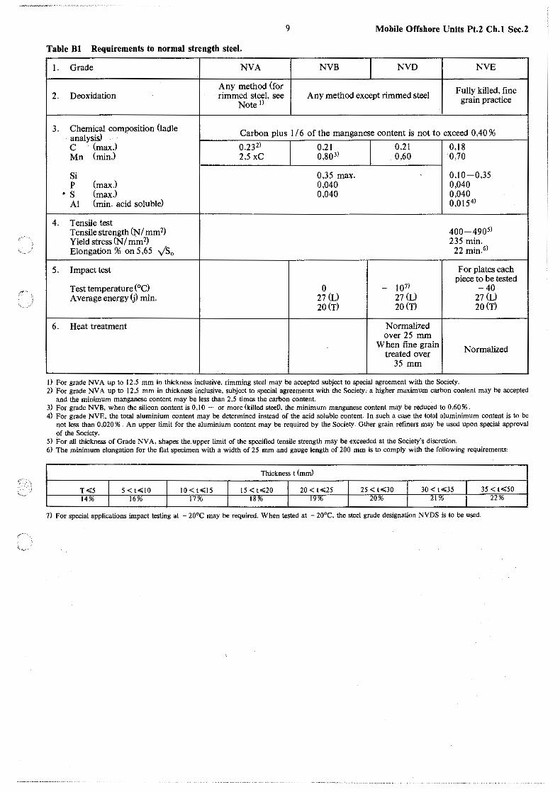
Table Bl Requirements to normal strength steel.
I. Grade NVA NVB NVD NYE
Any method (for Fully killed, fine 2. Deoxidation rimmed steel, see Any method except rimmed steel
Note ll grain practice
3. Chemical composition (ladle Carbon plus 1I6 of the manganese content is not to exceed 0,40 % analysisl · C (max.) 0.23 2) 0.21 0,21 0,18 Mn (min) 2,5 xC 0,803) 0,60 0,70
Si 0,35 max. 0,10-0,35 p (max.l 0,040 0,040
. s (max.) 0,040 0,040 Al (min. acid soluble) 0,0154)
4. Tensile test Tensile strength (NI mm2) 400-4905)
Yield stress (N/ mm2) 235 min. Elongation % on 5,65 yS0
22 min.0>
5. Impact test For plates each piece to be tested
Test temperature (°C) 0 - 101> -40 Average energy (j) min. 27 (L) 27 (L) 27 (L)
20 (T) 20 (T) 20 (T)
6. Heat treatment Normalized over 25 mm
When fine grain Normalized treated over 35 mm
I) For grade NVA up to 12.5 mm in thickness inclusive, rimming steel may be accepted subject to special agreement with the Society. 2) For grade NV A up to 12,5 mm in thickness inclusive, subject to special agreements with the Society; a higher maximum carbon content may be accepted
and the minimum manganese content may be less than 2,5 times the carbon content. 3) For grade NVB, when the silicon content is 0,10 - or more (killed steeO, the minimum manganese content may be reduced to 0,60%. 4) For grade NVE, the total aluminium content may be determined instead of the acid soluble content. In such a case the total aluminimum content is to be
not less than 0.020 % . An upper limit for the aluminium content may be required by the Society. Other grain refiners may be used upon special approval of the Society.
5) For all thickness of Grade .NVA, shapes the. upper limit of the specified tensile strength may be exceeded at the Society's discretion. 6) The minimum elongation for the flat specimen with a width of 25 mm and gauge length of 200 mm is to comply with the following requirements:
Thickness t (mm)
T<5 I 5 < t<lO IO<t<l5 15<t<20 20 < t<25 25 < t<30 30 < t<35 35 < t<50 14% I 16% 17% 18"' 19'6 20% 21% 22%
7) For special applications impact testing at - 20°C may be required. When tested at - 20°C, the steel grade designation NVDS is to be used.

Mobile Offshore Units Pt.2 Ch. I Sec.2
C. High Strength Steel.
C 100 Steel grades.
IOI Four groups of yield strength. each consisting of three grades A. D and E. with different requirements to impact testing. are specified. Minimu1n upper yield stress for the four groups are:
265 N/mm2• denoted NV 27 315 N/mm2• denoted NV 32 355 N/mm2• denoted NV 36 390 N/mm2• denoted NV 40
Complete designation for the individual grades is to contain symbols for impact test requirement and yield strength group. Eg., NYE 32. Grades with minimum yield strength 265 and 390 NI mm' are given an additional symbol S. Eg., NVA 27 S
C 200 Chemical composition.
201 The analyses are in general to satisfy the following requirements:
C max.0.18% Si 0.10-0.50% Mn 0.9-1.6% P max. 0.040% S max. 0.040% Cu max. 0.35 % Cr max. 0.20% Ni max. 0.40 % Mo max. 0.08% Al ac. sol. max. 0.08 % Nb max. 0.05 % V max. 0.10%
For grade NV A 27S the maximum C-content is 0.20 % . For steel grades which according to Table Cl may be delivered semi-killed. the specified minimum Si-content is not applicable. For the following grades. a minimum Mn-content of 0.70 % is stipulated:
NV A27S. NVD27S. NVE27S regardless of thickness. - NV A32. NV A36. NV A40S with thickness equal to
and less than 12.5 mm.
For the following grades. a minimum Mn-content of 60 % is stipulated:
- NVA27S and NVD27S with Si-content above 0.10% regardless of thickness.
202 Grades which according to Table Cl are to be finegrain-treated. are to contain one or more of the elements Al. Nb and V. Other grain-refining elements may be used after agreement with the Society. The content of grainrefining elements of the various steel grades are subject to approval by the Society. When Al. Nb or V is used singely, the minimum content is to be:
Al, min. 0.015 % acid soluble or 0,020 % total content. - Nb, min. 0,02%. - V, min. 0,05 % .
A smaller content of Al may be accepted. subject to special approval. When used in combination, the specified minimum content of each element is not applicable.
203 The content of all elements specified is to be determined for each cast. by ladle analysis, and is to be stated in the certificate. The determination of Al. Nb. and V may be omitted for grades that are not fine-grain-treated.
204 If a carbon equivalent is asked for. the following formula with the ladle analysis values to be used:
C =C Mn Cr+Mo+V +Ni+ Cu lo' I oq + 6 + 5 J5 A>
10
C 300 Mechanical properties.
301 High strength steel is to comply with the requirements to deoxidation practice. fine-grain-treatment and mechanical properties as specified in Tables Cl and C2. Additional requirements concerning through thickness properties may be required, see E 500.
302 For delivery testing, the minimum elongation for flat tensile test specimens, according to Sec. 1 C 406, Alternative A is to comply with the requirements given in Table C3.
Table Cl Deoxidation and grain refining treatment of high strength steel.
Steel grade Deoxidation Grain-refining treat-ment
NV A27S semikilled or killed -
NV D27S semi killed or killed 11 - ii
NV E27S killed yes
NV A32 killed21 -NVD32 killed 21 yes
NVE32 killed yes
NV A36 killed21 -
NVD36 killed yes
NVE36 killed yes
NV A40S killed yes
NVD40S killed yes
NV E40S killed yes
I) For thicknesses 25.5 mm and above the steel is to be killed and finegrain-treated unless otherwise agreed upon the Society.
2) Semi-killed steel may be accepted by agreement with the Society.
Table C2 Mechanical properties.
Steel grade Tensile test
Yield stress Tensile Elongation2>
R,HN/mm2 strength L0 = 5.65 ySa min. Rm.N/mm2 9(), min.
NV A27S
NVD27S 265 400-510" 22
NVE27S
NV A32
NVD32 315 440-590 22
NVE32 •
NV A36
NVD36 355 490-620 21
NVE36
NV A40S
NVD40S 390 530-650 20
NV E40S
(
(
'<.
~'.
" ~~.:,
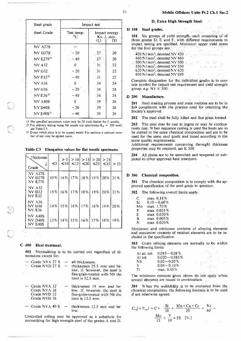
Steel grade Impact test
Steel Grade Test temp. Impact energy cc Kv. J, min.
(L) (T)
NV A27S -
NV D27S - 20 27 20
NV E27S3' -40 27 20
NV A32 0 JI 22
NVD32 - 20 31 22
NV E32 3' -40 31 22
NV A36 0 34 24
NVD36 - 20 34 24
NV E36·" - 40 34 24
NV A40S 0 39 26
NVD40S - 20 39 26
NV E40S3' -40 39 26
l) The specified maximum value may be 20 units higher for E quality. 2) For delivery testing using nat tensile test speciments (L0 = 200 mm).
see Table CJ. 3) Every rolled piece is to be impact tested. For sections a reduced num
ber of test may be agreed upon.
Table C3 Elongation values for flat tensile specimens.
rs::s >5 > 10 > 15 > 20 > 25
.t <5 ~10 < 15 <20 <25 <35 > 35 Grade
NV A27S NV D27S l 5 ?f'i 16 9f'1 17% 18% 19% 20% 2 I 9f'1 NV E27S
NV A32 NV D32 15% 16% 17% 18 9f'1 19% 20 9(, 21 % NV E32
NV A36 NV D36 14% 15% 16 9() 17 9f"1 18 9(, 19% 209() NV E36
NV A40S NV D40S 13 9() 149() 15% 16% 17% l 8 9() 19 9f"1 NV E40S
C 400 Heat treatment.
401 Normalizing is to be carried out regardless of dimensions except for:
Grade NV A 27 S - Grade NVD 27 S
Grade NVA 32 Grade NVA 36 Grade NVD 32 Grade NVD 36
Grade NV A 40 S
all thicknesses. thicknesses 25.5 mm and below: if, however. the steel is fine-grain-treated with Nb the limit is 12.5 mm.
thicknesses 19 mm and below. If. however. the steel is fine-grain-treated with Nb the limit is 12 .5 mm.
thicknesses 12 .5 mm and below.
Controlled rolling may be approved as a substitute for normalizing for high strength steel of the grades A and D.
11 Mobile Offshore Units Pt.2 Ch.I Sec.2
D. Extra High Strength Steel.
D 100 Steel grades.
IOI Six groups of yield strength, each consisting of of three grades D. E and F. with different requirements to impact testing are specified. Minimum upper yield stress for the four groups are:
420 N/mm'. denoted NV 420 460 N/mm2• denoted NV 460 500 N/mm'. denoted NV 500 550 N/mm2• denoted NV 550 620 N/mm'. denoted NV 620 690 N/mm'. denoted NV 690
Complete designation for the individual grades is to contain symbol for impact test requirement and yield strength group. e.g. NV E 500.
D 200 Manufacture.
201 Steel making process and main routines are tb-be in full compliance with the practice used for obtaining the Society's approval.
202 The steel shall be fully killed and fine grain treated.
203 The steel may be cast in ingots or may be contiiluously cast. '\\-'hen sequence casting is used the heats are to be melted to the same chemical composition and are to be used for the same steel grade and tested according to the same quality requirements. Additional requirements concerning throught thickness properties may be required. see E 500.
204 All plates are to be quenched and tempered or subjected to other approved heat treatment.
D 300 Chemical composition.
301 The chemical composition is to comply with the approved specification of the steel grade in question.
302 The following overall limits apply:
c Si Mn p s B N
max. OJ 8 % 0.10-0.60% max. 1.70% max. 0 .025 % max. 0.020 9f"1 max. 0 ,005 96 max. 0.020%
Maximum and m1n1mum contents of alloying elements and maximum contents of residual elements are to be included in the specification.
303 Grain refining elements are normally to be within the following limits:
Al ac. sol. 0.015-0.08% Al tot. 0.020-0.085 % Nb 0.02-0.05 % v 0.04-0.10% Ti 1nax. 0.05 9(>
The minimum contents given above do not apply when several elements are issued in co1nbinatioi1.
304 When the weldability is to be evaluated from the chemical composition, the following formula is to be used if not otherwise agreed:
Ccq( =Pcm) = C + Si Mn+Cu+Cr Ni 30 + 20 + 60 +
Mo ~+SB !W.J 15+ 10

Mobile Offshore Units Pt.2 Ch.I Sec.2
D 400 Mechanical properties.
401 Mechanical properties of the steel are to be in compliance with the requirements given in Table DI . Additional requirements concerning through thickness properties may be required, see E 500.
402 Drop weight testing and/ or fracture mechanical testing. according to agreed procedure may be required where found appropriate by the Society.
Table Dl Mechanical properties for extra high strength steels.
Grade Tensile test
Yield stress Tensile Elongation, 9ri N/mm2• strength L0 =5.65 ~
min N/mm2 min.
NVD420 NVE420 420 530-680 18 NVF420
NVD460 NVE460 460 570-720 17 NVF460
NVD500 NVE500 500 610-770 16 NVF500
NVD550 NVE550 550 660-830 16 NVF550
NVD620 NVE620 620 720-890 15 NVF620
NVD690 NVE690 690 770-940 14 NVF690
Grade Impact test (KV)
Test temp. C0 Impact energy J, min.
Average Single value value
NV D420 -20 NV E420 -40 NVF420 -60
NV D460 -20 NV E460 -40 NVF460 -60
NV D500 -20 NV E500 -40 NV F500 -60
NV D550 -20 NV E550 -40 40 (L) 27 (L) NV F550 -60 27 (T) 20 (T)
NV D620 -20 NV E620 -40 NV F620 -60
NVD690 -20 NV E690 - -40 NV F690 -60
E. Testing.
E 100 Samples for testing.
12
101 The sample of material from which the test specimen is cut is to be treated together with and in the same
way as the material represented by the sample. Test samples are not to be separately heat treated in any way.
102 Unless otherwise agreed, the test samples for tensile and impact test specimens are to be taken from the following positions:
plates and flats wider than 400 mm: From one end at a position approximately midway between the axis in the direction of rolling and the edge of the rolled product. see Fig. I a. flats having a width of 400 mm or less, bulb flats and other sections: From one end at a position approximately one third from the outer edge, see Fig. 1 b and d. or in the case of small sections. as near as possible to this position. In the case of channels, beams or bulb angles the test specimens may alternatively be taken from a position approximately one quarter of the width from the web centre line or axis. see Fig. I c and ct. Bars and other similar products: So that the axis of the test specimen are to be as near as possible to the following:
1/4
1/4
@
114[ 1/4
112
©
·112 b ®
~ 1/4~ 1/4
L.Lj.
112
@
~213 13
.
• Fig. 1 Position of test specimen.
For cylindrical sections. at one third of the radius from the outside. see Fig. 1 e. For non-cylindrical sections. at one third of the half diagonal from the outside. For small sizes. the tensile test specimen may consist of a suitable length of the full cross-section of the product.
Samples for testing of through thickness properties are to be taken according to Sec. I C 800.
E 200 Tensile testing.
201 Tensile test specimens are to be cut with their longitudinal axes transverse to the final direction of rolling, except in the cases of sections. bars and rolled flats with a finished width of 600 mm or less.
202 For each batch presented, one tensile test is to be made from one piece unless the weight of finished material is greater than 50 tonnes. in which case one extra test is to be made from a different piece from each 50 tonnes or fraction thereof. Additional tests are to be made for every variation of 5 mm in the thickness of plate from the same cast. For sections and bars. additional tests are to be made for every variation of 20 96 in cross-sectional dimension. For the extra high strength steel the following additional requirements apply:
(
(

Each tensile test is in any case to represent one heat treatment batch only.
203 When no distinct yield is observed during tensile testing the stress at 0.2 % non-proportional elongation is to be determined.
E 300 Impact testing.
301 Minimum impact energy values are specified for longitudinal (L) as well as for transverse (T) specimens. For delivery testing the impact specimens may be cut with their longitudinal axes parallel or transverse to the final direction of rolling except for extra high strength steel, where specimens are to be transverce to the rolling direction. 302 For plate thicknesses exceeding 50 mm impact test ~pecimens are to be situated so that the distance between the centerline of the test specimen and the -plate surface is not less than I I 4 of the plate thickness.
303 The notch in impact specimens is to be cut in a face
13
,..--- of the test specimen, which was originally perpendicular to the rolled surface.
,, .. -,
c"
'<.o ..
304 Where it is .impossible to use a standard impact test specimen I 0 x 10 mm. the larger of the following specimens is to be used: 10 x 7.5 mm, IO x 5 mm. The impact values are then reduced to respectively 5 I 6 and 2/ 3 of the required values of the standard test specimen.
305 Extent of impact testing. Normal strength steel.
Plates' For each batch presented of grade NVB and grade NVD from the same cast, one rolled piece is chosen for impact testing. If the weight of finished material is greater than 50 tonnes, an additional piece is to be selected from each 50 tonnes or fraction thereof. For plates in grade NVD, delivered controlled rolled instead of normalized, an additional piece is to be selected from each 25 tonnes or fraction thereof if the finished material from the same cast is greater than 25 tonnes. The pieces selected are to be the thickest in each batch. For NVE the impact test is to represent one piece only. Where parts of the rolled piece are heat treated in different batches, one set of impact test specimens is to be taken from each heat treatment batch. Flats, sections and bars: For grades NVB and NVD one set of impact tests is to be made for each 50 tonnes, and for grade NYE for each 25 tonnes of product produced from the same cast. For products accepted delivered controlled rolled instead of normalized, one set of impact tests is to be made for each 2 5 tonnes product produced for grade NVD and each 15 tonnes for grade NYE. Additional tests are to be made for every variation of 20 % in cross-sectional dimensions. For grade NVB with thicknesses 25 mm and less. and for grade NVD, delivered killed, fine grain-treated and normalized a reduction of the number of impact tests may be permitted by special agreement with the Society.
306 Extent of impact testing. High strength steel.
For materials, heat treated according to C 401 the following regulations normally apply: For each batch presented from the same cast, one piece is chosen for impact testing. If the weight of finished material from the same cast is greater than 50 tonnes, an additional piece is to be selected from each 50 tonnes or fraction thereof. The pieces selected are to be the thickest in each batch. One set of three Charpy V-notch test specimens is to be made from each of the selected pieces. For NVD delivered in the normalized condition and NV A delivered in conditions according to C 401 a reduction in the number of impact tests may be permitted after agree-
Mobile Offshore Units Pt.2 Ch.I Sec.2
men! with the Society. For grades delivered in the controlled rolled condition each rolled piece is normally to be subjected to impact testing. For steel of grad Ethe impact test is to represent one rolled piece only. Where parts of the rolled piece are heat treated iri different batches. one set ·of impact test specimens is to be taken from each heat treatment batch. If the works submit comprehensive test data from the running production, verifying that the specified requirements are consistently met, a reduction of number of impact tests may be permitted after agreement with the Society.
307 Extent of impact testing. Extra high strength steel. For extra high strength steel each rolled piece is to be subjected to impact testing. Where parts of the rolled piece are heat treated- in different batches, one set of impact test specimens is to be taken from each heat treatment batch.
E 400 Re-testing.
401 In the following the term «piece» is defined as the rolled product from one sirigle slab or bloom. In certain cases it can also be the rolled product from one single ingot if plates, bars or sections are rolled directly from the ingot.
402 By cast or batch testing of rolled products the following apply,
When the tensile test from the first piece fails to meet the requirements. two further tenSile tests may be -made from the same piece. If both of these additional tests are satisfactory, this piece and the remaining pieces from the same batch may be accepted. If one or both of the additional tests are unsatisfactory, the piece is to be rejected, but the remaining material from the same batch may be accepted, provided that two of the remaining pieces in the batch. selected in the same way, are tested with satisfactory results. When the average value of the three initial Charpy V-notch impact specimens fails to meet the stated requirement. or the value for more than one specimen is below the required average value, or when the value for only one specimen is below 70 9(> of the specified average value, three additional specimens from the same material may be tested and the results added to those previously obtained to from a new average. If this new average complies with the requirements and if no more than two individual results are lower than the required average and no more than one result is below 70 % of the specified average value the piece or batch may be accepted.
403 \\'hen each piece is tested, the regulations given above for the first piece selected apply.
404 When a batch of material is tested and the tested piece do not meet the requirements. the remaining pieces in the batch may be re-submitted individually for testing, and those pieces which give satisfactory results may be ac~ cepted.
405 If any test specimen fails because of faulty preparation or visible defects, the defective test speCimen may, at the Surveyor's discretion, be discarded and replaced by an additional specimen of the same type. An additional test specimen of the same type may also be taken if the elongation value is considered to be not valid according to Sec. IC 400.
406 Rejected material may be re-submitted after heat treatment or re-heat treatment. or may be re-submitted as

Mobile Offshore Units Pt.2 Ch.I Sec.2
another grade of steel. and may then be accepted. provided the required tests are satisfactory.
E 500 Testing of through thickness properties.
501 Steel specified with improved through thickness properties (Z-steel) is to be tested as detailed in Sec. l C 800. When not otherwise agreed. the minimum average value for the reduction of area of three tensile test specimens ta· ken in the thickness direction of the product is to be at least 25 % . Only one individual value may be below the minimum average value, but the reduction of area is not to be less than 20 % . For rolled pieces with mass more than 20 tonnes, three specimens from each end are to be tested and "in that case two_ individual specimens may give values of minimum 20%.
502 When the tensile test fails to meet the requirements given in 50 l three further specimens from each test sample may be tested. [f the average value for all six. resp. twelve specimens is at least 25 % , the tensile test will be regarded as past.
503 The product is to be subjected to ultrasonic inspection according to an appropriate standard. with established criteria accepted by the Society.
504 Steel processed to obtain improved through thickness properties and complying with the requirements given in 501. 502 and 503 are to be marked with the suffix Zin addition to the material grade designation, e.g. NVD Z. NVE 36 Z.
E 600 Inspection - tolerances.
601 Surface inspeCtion and checking of dimensions are the responibility of the steelmaker who has to verify that the requirements to quality and dimensional tolerances are fulfilled prior to despatch. The steelmaker is also responsible for compliance with the general requirements concerning freedom from harmfull internal defects. Acceptance by the Surveyors of material which later is found to be defective shall not absolve the steelmaker from this responsibility.
602 Plates and other products of extra higher strength
14
steel are to be subjected to a thorough, visual inspection on both sides by the manufacturer to ensure freedom from defects and harmfull imperfection. Examination by means of suitable non-destructive methods such as magnetic partiCie and/ or ultrasonic inspection may be required.
603 The plate thicknesses are to comply with the following minus tolerances:
Up to 10 mm: Max 0,3 mm Over I 0 and up to 30 mm: Max. 0.5 mm. Over 30 mm: 2 % • but not more than I mm.
604 For seamless structural tubes the tolerances for outer diameter, wall thickness and· out-of roundness are to be defined and agreed upon prior to starting the production.
F. Repairs.
F 100 Surface defects.
IOI Surface defects in structural steel may be removed by local grinding. provided that the thickness is in no place reduced to less than 9 3 % of the nominal thickness. and in no case by more than 3 mm. The extent of such repairs is to be agreed with the Surveyor in each case. The repairs are to be carried out under the Surveyor's supervision unless otherwise agreed.
102 Surface defects which cannot be dealt with as above. may subject to the Surveyors consent be repaired by chipping or grinding followed by welding. under his supervision, provided the regulations given below are complied with.
after removal of the defect, and before welding, the thickness of the piece is in no place to be reduced by more than 20 % . The welding is to be carried out by skilled welders according to an approved procedure. with approved electrodes. The welding is to be ground smooth to the correct nominal thickness. the piece is normally to be subjected to an adequate heat treatment subsequent to the final grinding. In general the heat treatment is to be the same as prescribed for the steel grade in question.

r,-:
"'--~. -
15 Mobile Offshore Units Pt.2 Ch.l Sec.3
SECTION 3 ROLLED STEEL FOR BOILERS. PRESSURE VESSELS AND SPECIAL
APPLICATIONS Contents.
A General. A 100 Scope.
B Carbon and Carbon Manganese Steel. B 100 Steel grades. B 200 Chemical composition. B 300 Mechanical properties. B 400 Heat treatment.
C Alloy Steel. C 100 Steel grades. C 200 Chemical composition. C 300 Mechanical properties. C 400 Heat treatment.
D Testing. D l 00 Tensile testing. D 200 Impact testing. D 300 Drop weight testing. D 400 Bend testing. D 500 Inspection - tolerances.
E Identification of Materials. E 100 Branding.
A. General.
A 100 Scope.
101 The requirements in this Section specify rolled steel for boilers, pressure vessels and high/low temperature application. The Rules are not applicable to rolled slabs, billets or bars used as substitute for forgings.
B. Carbon and Carbon Manganese Steel.
B 100 Steel grades.
101 6 different groups of tensile strength are specified' NV 1. NV 2. NV 3, NV 4, NV 5, NV 6. Each group comprises several grades as specified in table B2. The steels are to be killed or semi-killed.
B 200 Chemical composition.
201 The chemical composition is to satisfy the specifications given for the respective steels in Table Bl. The contents of carbon. manganese, silicon, sulphur and phosphorus are to be determined. The content of residual elements is to be checked by random tests as agreed with the Surveyor. The following maximum contents of residual elements will be accepted' Chromium' 0,20%, Nickel' 0,30% Copper' 0,35%. For the grades NV 2-3, 2-4. and 3-4 and 4-4 a Nickel content of max. 0.80 % may be approved.
202 Steels for boiler and pressure vessels may be fine grain treated with aluminium. Other grain refining elements may be added subject to approval by the Society. The following maximum limits normally apply, Al soJ., 0.08%. Nb' 0.05%, v, 0.10%. For low temperature application fine-grain-treatment according to Table D 1 .
B 300 Mechanical properties.
301 The mechanical properties of the material at ambient temperatures are to comply with the requirements in Table B1.
302 Plate materials for constructions with design temperature 100° C or higher, are to satisfy the requirement to lower yield stress, Rel• or proof stress. Rp0.2. specified in Table B3 at the design temperature in question.
303 Stress rupture values for design purposes are given in the Table B4.
B 400 Heat treatment.
401 Carbon and carbon-manganese steels are to be normalized except for steels of the tensile strength groups l, 2 and 3, with thicknesses less than 25 mm intended for boiler and pressure vessels of Class II and III. The steel may also be delivered in quenched and tempered condition. In such cases t_he · specification for mechanical properties are to be submitted to the Society for approval. Other kinds of heat treatment are to be approved by the Society in each particular case.
C. Alloy Steels.
C 100 Steel grades.
101 3 groups are specified' NV 7, NV 20 and NV 25. each group comprising several grades as specified in Table C2. Group NV 7 comprises molybdenum and chromiummolybdenum alloy steel for high temperature service. Group NV 20 comprises nickel alloy steel for low temperature service. Group NV 25 comprises chromium nickel alloy austenitic steel for high and low temperature application and use under conditions where corrosion resistance is required.
C 200 Chemical composition.
201 The chemical composition is to satisfy the specifications given for the respective steels in Table CL All elements listed in Table Cl are to be determined. The content of residual elements is to be checked by random tests as agreed upon with the Surveyor. Residual elements are not to be present in amounts exceeding those specified in relevant standards.
C 300 Mechanical properties.
301 The mechanical properties of the material at ambient temperature are to comply with requirements given in Table C2.
302 Plate materials for boilers and other pressure vessels with design temperature 100° C or higher, are to satisfy the requirement to lower yield stress. Rel or proof stress. R p0.2 specified in Table C3 at the design temperature in question.
303 Stress rupture values for design purposes are given in the Table C4.

Mobile Offshore Units Pt.2 Ch. l Sec.3 16
Table Bl Chemical composition of carbon and carbon/ manganese steel 1)
C') Si Mn')
s p N') Semi-Grade % % % % % % killed H
max. I max. max. max. Killed T
NV 1--0 0,20 max. 0,4 ;;:: 0,40 0,050 0,050 0,009 HT
" 1-1 0,16 max. 0,4 ;;:: 0,40 0,050 0,050 0,009 HT
" 1-2 0,14 0,15--0,40 ;;:: 0,40 0,040 0,040 0,009 T
NV 2--0 0,20 max. 0,4 ;;:: 0,40 0,050 0,050 0,009 HT
" 2-1 0,16 max. 0,4 ;;:: 0,40 0,050 0,050 0,009 HT
" 2-2 0,16 0,15--0,40 ;;:: 0,40 0,040 0,040 0,009 T
" 2-3 0,14 0,15--0,40 0,70--1,60 0,035 0,035 0,009 T
" 2-4 0,14 0,15--0,50 0,70--1,603) 0,035 0,035 0,009 T
NV 3--0 0,20 max. 0,4 ;;:: 0,40 0,050 0,050 0,009 HT
" 3-1 0,16 max. 0,4 ;;:: 0,40 0,050 0,050 0,009 HT
" 3--2 0,16 0,15--0,40 ;;:: 0,40 0,040 0,040 0,009 T
NV 4--0 0,20 0,15--0,50 ::;: 1,60 0,050 0,050 0,009 T
" 4--1 0,16 0,15--0,50 ::;: 1,60 0,040 0,040 0,009 T
" 4--2 0,16 0,15--0,50 ::;: 1,60 0,040 0,040 0,009 T .. 4-3 0,15 0,15--0,50 0,70--1,60 0,035 0,035 0,009 T .. 4-4 0,15 0,15--0,50 0,70--1,603) 0,035 0,035 0,009 T
NV 5--0 0,20 0,15--0,50 0,90--1,20 0,050 0,050 0,009 T " 5-1 0,18 0,15--0,50 0,90--1,30 0,040 0,040 0,009 T
" 5-2 0,16 0,15--0,50 0,90--1,40 0,040 0,040 0,009 T
NV 6--0 0,23 0,15--0,60 1,00-1,30 0,050 0,050 0,009 T ,, 6--1 0,20 0,15--0,60 1,00-1,40 0,040 0,040 0,009 T ,, 6-2 0,18 0,15--0,60 1,00-1,50 0,040 0,040 0,009 T
1) Steel for design temperatures of max. 400°C may be fine-grain-treated with Al. For such material a max. content of0,015 % N is allowed.
2) The following carbon equivalent is to be satisfied:
Mn c + 10 .;032.
2) A higher value than 0,32 may be accepted by the Society, provided that preheating is used during welding. (A higher carbon content may be accepted for riveted constructions).
3) A max. Mn-content of 1,65 is accepted provided the carbon content does not exceed 0,13% for NV 2-4 and 0,14% for NV 4-4.

17 Mobile Offshore Units Pt.2 Ch.I Sec.3
Table B2 Mechanical properties of carbon and carbon/manganese steel.
Upper yield stress6 ) Impact Tensile ReH N/mm2 min. Elongation') test Permissible design
strength min.% KV at Bend test temp. ° C
Grade Rm
thickness in mm 5)
testing Diam. of
N/mm' t > 16 t> 40 Lo= temp. mandrel D')
I max. 4) t ,,; 16 t ,,; 40 t.,,; 60 200mm As 0 c 2) min.
NVl-0 360-440 235 235 225 - D=t + 15 450
" 1-1 " 235 235 225 20 26 0 0 450 ,, 1-2 " 235 235 225 -20 - IO 450
NV2-0 400-490 255 245 235 - D=2 x t + 15 450 ,, 2-1 " 265 255 245 0 0 450 •• 2-2 " 265 255 245 20 24 -20 - 10 450 .. 2-3 9)
.. 265 255 245 -40 - 35 450 " 2-49)
,, 265 255 245 - 55 - 507
) 450
NV3-0 430-510 275 255 245 - D=2X t + 15 450 ,, 3-1 " 275 255 245 20 24 0 0 450
" 3-2 ,,
275 255 245 -20 - IO 450
NV4-0 490--570 335 325 315 - D=3 x t + 15 450
" 4--1 ,,
335 325 315 0 0 450
" 4--2 " 335 325 315 18 21 -20 - 10 450 .. 4-3 9)
,, 335 325 315 - 40 - 35 450
.. 4-49) "8) 335 325 315 - 55 - 507 ) 450
NV5-0 460-550 285 I 215 265 - D=3 X t + 15 450 ,, 5-1
,, 285 275 265 19 21 0 0 450
" 5-2 " 285 275 265 - 20 - 10 450
NV6-0 510--610 325 315 315 - D = 3,5xt + 15 450
" 6-1 ,,
325 315 315 18 20 0 0 450
" 6-2 " 325 315 315 -20 - 10 450
I) For material thicknesses less than IO mm, the percentage elongation may be up to 3 units lower than-given in the Table. For plates of cold-flange quality, the elongation is to be at least 2 units greater than required for material which is not for cold-flanging.
2) For steel grades intended for design temperatures below - I 0°C, the test temperatures, stated in the Table, are those corresponding to the lowest permissible design temperature. Other regulations regarding test temperatures and required impact values are given under D 200.
3) t =thickness of the_ material. Regulations concerning bend test are given under D 400.
4) Semi·killed steel and steel which is fine·grain·treated with Al; design temperature max:. 400°C. 5) For plates and sections thicker than 60 mm, use table values for thickness up to 60 mm, reduced by I % for every 5 mm increase of
thickness. 6) When no distinct yield is observed, the proof stress 3.t 0,2 % elongation (Rp0.2) is to be determined. 7) The grades NV 2-4 and NV 4-4 may be used down to - 55°C provided impact testing is carried out at - 60°C. Materials tested at
- 60°C are to have.an additional designation L, eg. NV 2-4L. 8) For material thicknesses above 30 mm, the minimum value of Rm may be reduced 20 N/mm2 subject to approval by the Society. 9)Limitation of thicknesses for plates for !Ow temperature application is given in Table DI.

Mobile Offshore Units Pt.2 Ch.I Sec.3 18
Table B3 Yeld strength at elevated temperature for carbon and carbon/ maganese steel.
Minimum R.L or RPo,2' N/mm2, Steel Plate thickness at design temperature grade t mm')
100° c 1150° c I 200° c I 250° c 1300° c 1350° c 1400° c 1450° c t ::;;; 16 206 186 172 157 142 123 ll8 ll3
NV 1 16 < t ::;;; 40 196 186 172 157 142 123 ll8 ll3 40 < t ::;;; 60 181 177 167 157 142 123 ll8 ll3
t ::;;; 16 221 201 186 172 152 137 128 128 NV2 16 < t ::;;; 40 2ll 201 186 172 152 137 128 128
40<t:s;;60 196 191 186 172 152 137 128 128
t ::;;; 16 235 216 201 186 172 152 142 137 NV 3 16 < t ::;;; 40 225 216 201 186 172 152 142 137
40<t:s;;60 216 206 201 186 172 152 142 137
t ::;;; 16 299 289 275 250 2ll 181 167 157 NV4 16 < t ::;;; 40 289 280 265 240 206 181 167 157
40<t :;;;60 280 270 255 231 206 181 167 157
t ::;;; 16 265 245 231 2ll 191 172 162 157 NV 5 16 < t ::;;; 40 260 240 226 2ll 191 172 162 157
40 < t ::;;; 60 250 235 221 206 191 172 162 157
NV 6 I t ::;;; 60 I 284 I 275 I 255 I 235 I 216 I 201 I 177 I 157
I) For plates thicker than 60 mm, use table values for thickness for 60 mm. and reduce by 1 % for every 5 mm increase of thickness.
Table B4 Average values for stress to rupture in 100 000 hours.
Temperature N/mm2 1)
oc NVl,2and3 NV 4, 5 and 6
380 165 390 148 198 400 132 177 410 ll 8 156 420 103 136 430 91 ll9 440 79 103 450 69 88 460 (59) (76) 470 (SO) (64) 480 (42) (53)
I) V a1ues in brackets for temperatures over the highest permissible design temperatures are given for information.only.
(

,:·:
'.;_-~----'
19 Mobile Offshore Units Pt.2 Ch.I Sec.3
Table Cl Chemical composition of alloy steel.
c Si Mn
s p Cr Ni Mo
Grade % % % % % % % % max. _max. max.
NV 7-1') 0,20 0,15--0,35 0,40-0,80 0,040 0,040 - - 0,25--0,50
NV 7-2 0,18 0,15-0,35 0,40-0,90 0,040 0,040 . 0,70-1,10 - 0,40-0,70
NV 7-3 0,18 0,15--0,50 0,30--0,60 0,040 0,040 2,00-2,50 - 0,90-1,10
NV 20-003 ) 0,10 0,15--0,35 0,40--0,70 0,025 0,020 - min. 2,25 -
NV 20--03) 0,10 0,15--0,35 0,40-0,70 0,025 0,020 - min. 3,25 -
NV 20-1 3) 0,10 0,15--0,35 0,40--0,70 0,025 0,020 - min. 4,75 -
NV 20-23) 0,08 0,15--0,35 0,40--0,70 0,025 0,020 - min. 9,00 -
NV 25-1 0,05 ~ 1 ~ 2 0,030 0,040 17-20 iii; 8 -
NV 25-22) 0,08 ~ 1 ~ 2 0,030 0,040 17-20 iii; 8,5 -NV 25-3 0,05 ~ 1 ~ 2 0,030 0,040 16,5-20 iii; 9,5 1,3-3,3
NV 25-42) 0,08 ~ 1 ~ 2 0,030 0,040 16,5-20 iii; 10 1,3-3,3
1) Aluminium is not to be added to this grade. 2) NV 25-2 and NV 25-4 are to be stabilized with either Ti or Nb, and the percentages of these elements are to be:
Ti :::: min. 5 x C% and max. 0.7 % Ti. Nb = min. 10 x C% and max. 1,0% Nb.
2) Nb maY be partly replaced by Ta, but the quantity of Ta is not to be greater than 1I3 of the Nb-content. 3) Al sol. 0.02-0,08 % .
Table C2 Mechanical properties of alloy steel.
Upper yield stress•) Elongation Reduc- Impact Tensile R.n N/mm1 min. Permissil;lle design strength % tion of test temp. •c
Grade Rm Thickness mm3) min. area. KV at
N/mm• t > 16 Lo= Z% testing
min. t :;; 16 200 mm A, min. temp. •c Highest Lowest t :;;;: 60 .
NV 7-1 430 275 265 22 500 NV 7-2 430 305 295 22 550 NV 7-3 440 275 265 20 580
NV20-oos> 390 315 315 21 25 60 - 705) - 65
NV20-os> 440 345 345 21 25 60 - 955) -90
NV20-1s> 490 390 390 21 256) 55 -1105) -105 NV20-2s> 690 515 515 18 207) 50 -196 -165
NV25-1 490 195 195 40 50
r!W) NV25-2 490 195 195 40 50 2) -196
NV25-3 490 195 195 40 50 NV25--4 490 195 195 40 50
I) Impact test only for design temperature below - I 05°C. 2) Max. design temperature to be approved in each case. 3) For plates thicker than 60 mm, use table values for thickness up to 60 mm. reduced by I% for every 5 mm increase of thickness. 4) When no distinct yield is observed, the proof stress at 0,2 % elongation (Rp0.2) is to be determined. 5) The test temperature is always to be at least I 0°C below design temperature for thicknesses t °' 20 mm, and at least 20°C below de-
sign temperature for thicknesses 20 mm < t < 30 mm. 6) 22 % may be accepted when Rm > 540 N/mm2.
7) 18 % may be accepted subject to special approval. 8) Limitation of thicknesses for plates for low temperature application is given in Table D2.
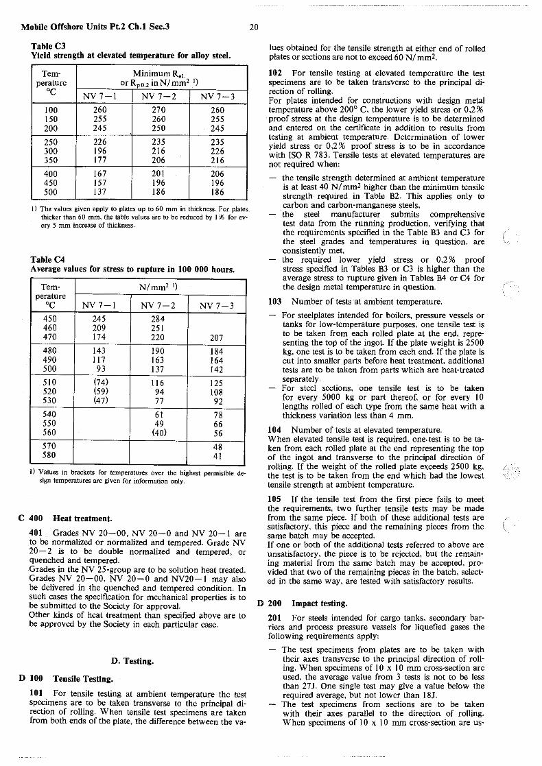
Mobile Offshore Units Pt.2 Ch.I Sec.3
Table C3 Yield strength at elevated temperature for alloy steel.
Tern- Minimum Rel perature orRpo.2 inN/mm' 1) oc
NV7-l NV7-2 NV7-3
100 260 270 260 150 255 260 255 200 245 250 245
250 226 235 235 300 196 216 226 350 177 206 216
400 167 201 206 450 157 196 196 500 137 186 186
J) The values given apply to plates up to 60 mm in thickness. For plates. thicker than 60 mm, the table values are to be reduced by I % for ev· ery 5 mm increase of thickness.
Table C4 Average values for stress to rupture in 100 000 hours.
Tern- N/mm2 1)
perature oc NV7-l NV7-2 NV7-3
450 245 284 460 209 251 470 174 220 207
480 143 190 184 490 117 163 164 500 93 137 142
510 (74) 116 125 520 (59) 94 108 530 (47) 77 92
540 61 78 550 49 66 560 (40) 56
570 48 580 41
I) Values in brackets for temperatures over the highest permisible de· sign temperatures are given for information only.
C 400 Heat treatment.
401 Grades NV 20-00, NV 20-0 and NV 20-1 are to be normalized or normalized and tempered. Grade NV 20-2 is to be double normalized and tempered, or quenched and tempered. Grades in the NV 25-group are to be solution heat treated. Grades NV 20-00, NV 20-0 and NV20- l may also be delivered in the quenched and tempered condition. In such cases the specification for mechanical properties is to be submitted to the Society for approval. Other kinds of heat treatment than specified above are to be approved by the Society in each particular case.
D. Testing.
D 100 Tensile Testing.
101 For tensile testing at ambient temperature the test specimens are to be taken transverse to the principal direction of rolling. When tensile test specimens are taken from both ends of the plate, the difference between the va-
20
lues obtained for the tensile strength at either end of rolled plates or sections are not to exceed 60 NI mm2.
102 For tensile testing at elevated temperature the test specimens are to be taken transverse to the principal direction of rolling. For plates intended for constructions with design metal temperature above 200° C. the lower yield stress or 0,2 % proof stress at the design temperature is to be determined and entered on the certificate in addition to results from testing at ambient temperature. Determination of lower yield stress or 0 ,2 % proof stress is to be in accordance with ISO R 783. Tensile tests at elevated temperatures are not required when:
103
the tensile strength determined at ambient temperature is at least 40 NI mml higher than the minimum tensile strength required in Table B2. This applies only to carbon and carbon-manganese steels, the steel manufacturer submits comprehensive test data from the running production, verifying that the requirements specified in the Table B3 and C3 for the steel grades and temperatures in question, are ·consistently met, the required lower yield stress or 0 ,2 % proof stress specified in Tables B3 or C3 is higher than the average stress to rupture given in Tables B4 or C4 for the design metal temperature in question.
Number of tests at ambient temperature.
For steelplates intended for boilers, pressure vessels or tanks for low-temperature purposes, one tensile test is to be taken from each rolled plate at the end, representing the top of the ingot. If the plate weight is 2500 kg, one test is to be taken from each end. If the plate is cut into smaller parts before heat treatment, additional tests are to be taken from parts which are heat-treated separately. For steel sections, one tensile test is to be taken for every 5000 kg or part thereof, or for every 10 lengths rolled of each type from the same heat with a thickness variation less than 4 mm.
104 Number of tests at elevated temperature. When elevated tensile test is required, one. test is to be taken from each rolled plate at the end representing the top of the ingot and transverse to the principal direction of rolling. If the weight of the rolled plate exceeds 2500 kg, the test is to be taken from the end which had the lowest tensile strength at ambient temperature.
105 If the tensile test from the first piece fails to meet the requirements, two further tensile tests may be made from the same piece. If both of these additional tests are satisfactory, this piece and the remaining pieces from the same batch may be accepted. If one or both of the additional tests referred to above are unsatisfactory, the piece is to be rejected, but the remaining material from the same batch may be accepted, provided that two of the remaining pieces in the batch, selected in the same way, are tested with satisfactory results.
D 200 Impact testing.
201 For steels intended for cargo tanks, secondary barriers and process pressure vessels for liquefied gases the following requirements apply:
The test specimens from plates are to be taken with their axes transverse to the principal direction of rolling. When specimens of I 0 x I 0 mm cross-section are used. the average value from 3 tests is not to be less than 27J. One single test may give a value below the required average, but not lower than l 8J. The test specimens from sections are to be taken with their axes parallel to the direction of rolling. When specimens of I 0 x I 0 mm cross-section are us-
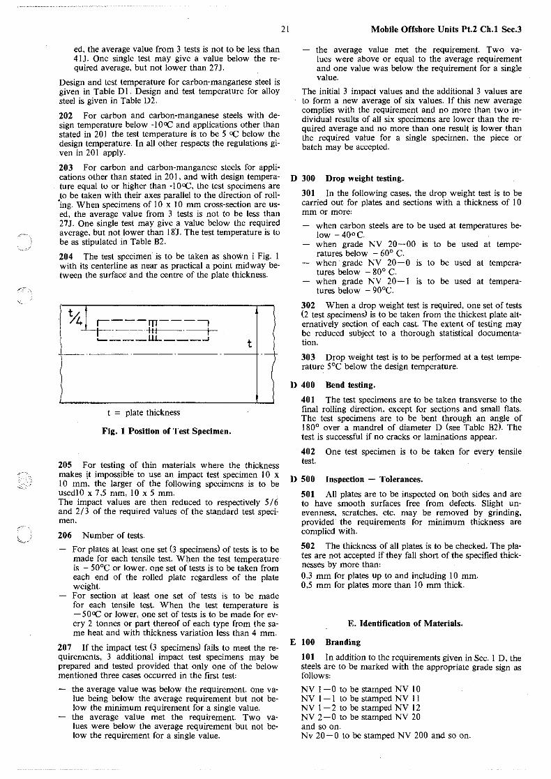
,<C''
/
::..-~~
ed, the average value from 3 tests is not to be less than 4 IJ. One single test may give a value below the required average, but not lower than 27J.
Design and test temperature for carbon-manganese steel is given in Table DI . Design and test temperature for alloy steel is given in Table D2.
202 For carbon and carbon-manganese steels with design temperature below -1 OCC and applications other than stated in 20 I the test temperature is to be 5 oC below the design temperature. In all other respects the regulations given in 20 I apply.
203 For carbon and carbon-manganese steels for applications other than stated in 20 I , and with design temperature equal to or higher than -I OoC, the test specimens are to be taken with their axes parallel to the direction of roll"'ing. When specimens of 10 x 10 mm cross-section are used, the average value from 3 tests is not to be less than 27J. One single test may give a value below the required average, but not lower than I BJ. The test temperature is to be as stipulated in Table B2.
204 The test specimen is to be taken as shown i Fig. I with its centerline as near as practical a point midway between the surface· and the centre of the plate thickness.
t.1.4= -m----, .1.4 r =--=-- +t+------- · -----t llL ___ _,
~-· --'----- . ----------------
t = plate thickness
t ----+·-
Fig. 1 Position of Test Specimen.
205 For testing of thin materials where the thickness makes it impossible to use an impact test specimen 1 0 x I 0 mm, the larger of the following specimens is to be usedlO x 7,5 mm, IO x 5 mm. The impact values are then reduced to respectively 5 I 6 and 2/ 3 of the required values of the standard test specimen.
206 Number of tests.
For plates at least one set (3 specimens) of tests is to be made for each tensile test. When the test temperature is - 50°C or lower, one set of tests is to be taken from each end of the rolled plate regardless of the plate weight. For section at least one set of tests is to be made for each tensile test. When the test temperature is -50CC or lower, one set of tests is to be made for every 2 tonnes or part thereof of each type from the same heat and with thickness variation less than 4 mm.
207 If the impact test (3 specimens) fails to meet the requirements, 3 additional impact test specimens may be prepared and tested provided that only one of the below mentioned three cases occurred in the first test:
the average value was below the requirement. one value being below the average requirement but not below the minimum requirement for a single value. the average value met the requirement. Two values were below the average requirement' but not below the requirement for a single value.
21 Mobile Offshore Units Pt.2 Ch.I Sec.3
the average value met the requirement. Two values were above or equal to the average requirement and one value was below the requirement for a single value.
The initial 3 impact values and the additional 3 values are to form a new average of six values. If this new average complies with the requirement and no more than two individual results of all six specimens are lower than the required average and no more than one result is lower than the required value for a single specimen, the piece or batch may be accepted.
D 300 Drop weight testing.
301 In the following cases, the drop weight test is to be carried out for plates and sections with a thickness of I 0 mm or more:
when carbon steels are to be used at temperatures below -40oC. when grade NV 20-00 is to be used at temperatures below - 60° C. when grade NV 20-0 is to be used at temperatures below - 80° C. when grade NV 20- I is to be used at temperatures below - 90°C.
302 When a drop weight test is required, one set of tests (2 test specimens) is to be taken from the thickest plate alternatively section of each cast. The extent of testing may be reduced subject to a thorough statistical documentation.
303 Drop weight test is to be performed at a test temperature 5°C below the design temperature.
D 400 Bend testing.
401 The test specimens are to be taken tran~verse to the final rolling direction, except for sections and small flats. The test specimens are to be bent through an angle of 180° over a mandrel of diameter D (see Table B2). The test is successful if no cracks or laminations appear.
402 One test specimen is to be taken for every tensile test.
D 500 Inspection - Tolerances.
501 All plates are to be inspected on both sides and are to have smooth surfaces free from defects. Slight unevenness, scratches, etc. may be removed by grinding, provided the requirements for minimum thickness are complied with.
502 The thickness of all plates is to be checked. The plates are not accepted if they fall short of the specified thicknesses by more than: 0,3 mm for plates up to and including I 0 mm. 0,5 mm for plates more than I 0 mm thick.
E. Identification of Materials.
E 100 Branding
101 In addition to the requirements given in Sec. I D, the steels are to be marked with the appropriate grade sign as follows'
NV 1-0 to be stamped NV I 0 NV 1 - I to be stamped NV I I NV 1-2 to be stamped NV 12 NV 2-0 to be stamped NV 20 and so on. Nv 20-0 to be stamped NV 200 and so on.

Mobile Offshore Units Pt.2 Ch.l Sec.3 22
Table D 1 Design and test temperature for carbon manganese steels.
Minimum
Grade Additional requirement design Impact test temperature Limitations
temperature (0 C) (OC)
NV 2-3 Fine-grain-treated with - 35 5° C below the design Maximum thickness NV 4-3 aluminium') temperature, but not 30mm 2)
higher than - 20° C
NV 2-4 - 50
NV4-4
NV 2-4L NV 4-4L - 55 - 60
Hull structural To be approved in each - IO Specified at - 20 Max. thickness 20 mm. • steel separate case. Not acceptable for inde-
- 25 Specified at - 40 pendent tanks type B & C and cargo process pres-
sure vessels
1) Other grain refining elements may be added, see B 202. 2) For materials more than 30 mm thick, the Charpy V-test requirements are to be specially agreed, but will not be less severe than given
in the table.
Table 02 Design and test temperature for alloy steels (Maximum thickness 30 mm)O
Minimum
Grade Type of steel design
Impact test temp ° C 1) tempera-ture ° C
NV 20-00 2 1/4 % Nickel - 65 W" C >dow ''''" ~'}'"' oo< _ m (NV "'-"'J NV 20- 0 3 1/2 % Nickel - 90 fort ,,;; 20 mm higher _ 95 (NV 20- 0)
NV 20- I 5% Nickel - 105 20° C below design temp. than: _ 110 (NV 20- I) for20<t~30mm
NV 20- 2 9% Nickel - 165 - 196 NV 25 Austenitic 18/8 - 196 - 1962
)
I) For materials more than 30 mm thick. the Charpy V-test requirements are to be specially agreed. but will not be less severe than those specified for 20 < t < 30 mm.
2) Impact testing is required only for design temperatures below - I 05°C.
(
,.,~,_
'.,-·
~,._/
23 Mobile Offshore Units Pt.2 Ch.I Sec.4
SECTION 4 CLAD STEEL PLATES
A. General. A 100 Scope. A 200 Heat treatment.
B. Base Material. B 1 00 General.
C. Cladding Metal. C 100 General.
Contents.
C 200 Chemical composition.
D. Testing. D I 00 General. D 200 Tensile testing. D 300 Impact testing. D 400 Bend testing. D 500 Shear testing. D 600 Ultrasonic testing. D 7 00 Corrosion testing. D 800 Inspection - tolerances.
E. Repair and Rejection. E 100 Surface defects. E 200 Rejection.
F. Identification of Materials. F 100 Branding.
A. General.
A 100 Scope.
101 The requirements in this Section specify clad steel plates consisting of a base material and a thinner layer (cladding metaO on one or both sides. continuously and integrally bonded.
A 200 Heat treatment.
201 The plates are to be supplied in that condition of heat treatment which is most appropriate for both types of material. The material is not to be subjected to any kind of heat treatment by the user, beyond what is recommended by the manufacturer and approved by the Society. The heat treatment is to be checked by the Surveyor.
B. Base Material.
B JOO General.
101 Any steel which is suitable for joining with the cladding metal, may be accepted as base material, provided that the process has not adverse effects on the finished plate. If the plate is intended for participation in the vessel's strength. the base material is at least to satisfy the requirements for corresponding hull materials. If the plates are intended for boilers or pressure vessels, the base material is to at least to satisfy the requirements to materials for such components. Work ·s certificate stating chemical composition to be supplied by the manufacturer
C. Cladding Metal.
C 100 General.
101 The thickness of the cladding metal is subject to approval in each case.
C 200 Chemical composition.
201 Cladding metal of austenitic stainless steel is to be delivered either with a low carbon content, i.e. max. 0,05 % , or it is to be stabilized as stated in Section 3 C 200 for steel NV 25-2 and NV 25-4. Other stainless steels. nickel and nickel-base alloys will be accepted, when they are suited for the intended service.
Note: NV 25-2 and NV 25-4 are to be stabilized with either Ti or Nb. and the percentage of these elements is to be:
Ti = min. 5 x C% and max. 0.7% Ti. Nb = min. 10 x C% and max. 1.0 Nb.
Nb may be partly replaced by Ta. but the quantity of Ta is not to be greater than I I 3 of the Nb-content.
202 Works' certificate to be supplied by the manufacturer. The manufacturer is to guarantee that the analysis complies with the requirements of the specification. Check analysis is to be made if required by the Society.
D. Testing.
D 100 General.
101 Tensile and bend test specimens are to be of the flat type. The test specimens are normally to have the full thickness of the plate. Where the thickness of the plate is more than 50 mm, or if necessary for the capacity of the testing machine. the thickness of the test specimen may be reduced by machining. On single clad plates, both sides ·of the test specimen are to be machined to maintain the same ratio of cladding metal to base steel as in the plate. but the cladding metal need not be reduced to less than 3 mm. Test specimens of double clad plates may be reduced by dividing. In this case. both halves are to be tested. Impact test specimens, if any, are to be taken fr6m the base material.
D 200 Tensile testing.
201 One set of tensile tests consists of two tests. One test from the full clad plate which is to have a tensile strength a8 not less than derived from the following formula: R = m
where:
S1 Rm1 + S2 Rm2 N/mml s
Rm1 = minimum tensile strength of base metal. Rm2 = minimum tensile strength of the cladding metal. S = nominal thickness of the clad plate = S1 + S2 . S1 = nominal thickness of the base metal. S2 = nominal thickness of the cladding metal.
One test of the base metal after removal of the cladding metal. The test is to satisfy the requirements for the base material.
202 From hull steel, one set of tensile tests is to be taken from every fifth plate, and at least one set from each cast and each thickness interval (see Section 2 E 200). From steel for pressure vessels, one set of tensile tests is to be taken from each plate.
Mobile Offshore Units Pt.2 Ch.I Sec.4
D 300 Impact testing.
301 If impact tests are required, they are to comply with the requirements sp·ecified for the base material in each case.
D 400 Bend testing.
24
401 The bend test specimens are to be bent l 80°C around a former without showing signs of cracking or loosening of the cladding· metal from the base material. The diameter of the former is to be twice the plate thick· ness when the tensile strength of the plate is less than 490 NI mm2, and three times the thickness of the plate when the tensile strength is more than 490 NI mm2. Two bend tests are to be taken from each plate. On single clad plates. one test specimen is to be bent with the cladding in ten~ sion and the other with the cladding in compression. On double clad plates, the test specimens are to be bent, so that both cladding metals are tested both ways.
D 500 Shear testing.
501 If shear test is required to decide the shear strength between the base and the cladding metal, one shear test is to be made from each plate in accordance with ASTM A 264. The shear strength is to be at least 140 NI mm2.
D 600 Ultrasonic testing.
601 To check the bonding. ultrasonic testing is to be made. If bonding defects are found, their extent is to be clearly marked and reported to the Surveyor. Rules for re· pairs are given in E I 00 and E 203. The area adjacent to the edges of each plate is to be checked 100 % for a width of at least 50 mm. Further tests are to be made at points equally distributed on the surface with max. intervals of 150 mm.
D 700 Corrosion testing.
701 If it is required to determine the resistance of the cladding metal against intergranular corrosion, the copper sulphate test according to ASTM A 26 2 Practice E is to be used. Note: By adding approx. 50 gram electrolytic copper to I 000 millilitres solution. the boiling time can be reduced to 15 hours. The base material is to be removed before the testing.
D 800 Inspection - tolerances.
801 Each plate is to be surveyed before delivery. The plates are to satisfy the requirements to minus tolerances on thickness as stipulated in Sec. 3 D 500. The thickness control is to be carried out by the manufacturer and the results submitted to the Surveyor.
E. Repair and Rejection.
E 100 Surface defects.
101 Minor surface defects and bonding defects which do not exceed the limits specified in E 203. may be repaired by means of welding. Bonding defects along the edges are to be repaired. Before welding, the defects are to be reported to the Sur· veyor for approval of the repair. Approved filler metal and welding processes are to be used.
E 200 Rejection.
201 If one of the mechanical tests does not satisfy the specified requirements. two new tests may be taken, both of which have to satisfy the requirements.
202 If the results of the chemical analysis deviate from the specifications. the results are to be submitted to the Society for decision whether the plates will be accepted.
203 The plate will be rejected if,
a repair will cause a weakening -'of the plate. a bonding defect exceeds 4 dm2 for plates up to 15 mm in thickness and 8 dm2 for plates over 15 mm or several bonding defects amounting to more than 2 % of the surface of the plate revealed.
F. Identification of Materials.
F 100 Branding.
101 The plates are to be marked according to the direc· tions given in Section 1 D. On single clad plates, the marking for both the base and cladding metal is to be stamped on the surface of the base plate. On double clad plates. all marking is done with a colour seal rather than by stamping.
/ i.
,r·,
25 Mobile Offshore Units Pt.2 Ch.I Sec.5
SECTION 5 STEEL TUBES AND PIPES
A General. A 100 Scope. A 200 Steel grades. A 300 Manufacture.
Contents.
A 400 Chemical composition. A 500 Mechanical properties. A 600 Heat treatment.
B Testing. B l 00 Test classes. B ,200 Tensile test. B 300 Flanging test. B 400 Ring tests. B 500 Impact test. B 600 Inspection - tolerances. B 700 Hydraulic pressure testing. B 800 Non-destructive testing. B 900 Corrosion testing. B 1000 Re-testing
A. General.
A 100 Scope.
10 I The requirements in this Section specify seamless and welded steel tubes and pipes.
A 200 Steel grades.
201 4 different groups are specified'
NVR l, NVR 7. NVR 20, NVR 25.
Each group comprises several grades as specified in Table A2. Group NVR I comprises carbon and carbon manganese steel tubes. Group NVR 7 comprises molybdenum and chromium-molybdenum alloy steel tubes. Group NVR 20 comprises nickel alloy steel tubes for low temperature service. Group NVR 25 comprises chromium nickel alloy austimitic steel tubes for high and low temperature application and use under conditions where corrosion resistance is required.
A 300 Manufacture.
301 Tubes and pipes of the grades NVR l and grade NVR 7 - 1 may be seamless or welded. Tubes and pipes of other grades are to be seamless, with the exception of NVR 25 which in certain cases may be welded subject to prior approval.
302 Welded tubes and pipes are to be produced by a continuous automatic electric welding process with or without filler metal. It is assumed that producers of welded tubes and pipes carry out running, non-destructive control. Welded tubes and pipes are not to be used for working pressures above 3 2 bar or design temperatures above 300°C. Further, they are not accepted for liquefied gases with temperatures below - l 0°C. Works may obtain approval by the Society for delivering welded tubes and pipes exceeding the above limitations. It is assumed that the producers of these tubes and pipes practice automatic non-destructive testing of welds. The whole length of the tube or pipe is to be controlled in this
way in addition to the testing specified below. Such tubes and pipes are considered equivalent to seamless types.
303 Tubes and pipes intended as strength members of structures are to satisfy the requirement.s to material for the structure in question, e.g. for hull and engine material.
A 400 Chemical composition.
401 Requirements to chemical composition are given in Table Al.
402 The steels may be fine grain treated with aluminium. Other grain refining elements may be added subject to approval by the Society. The following maximum limits normally apply,
Al sol.' 0,08%, Nb' 0,05%, v, 0,10%. Note: Fine grain treated steel is required in pipe systems for liquefied gases when the design temperature is below 0°C. The same applies for design temperature 0°C or above if the thicknesses are more than 20 mm.
A 500 Mechanical properties.
501 The mechanical properties of the material at ambient temperatures are to comply with the requirements in Table A2.
502 Tubes and pipes intended for piping systems with design temperature l 00°C or higher, are to satisfy the requirements to lower yield stress, ReL• or proof stress R p0.2 ,specified in Table A3 at the design temperature in question. Rp0,2 is to be determined when no distinct yield is observed.
503 Stress rupture values for design purposes are given in Table A4.
A 600 Heat treatment.
601 Tubes and pipes in the NVR I -group are in general to be normalized. Grade NVR 20-00 and NVR 20-0 are to be normalized or normalized and tempered. Grade NVR 20-2 is to be double normalized and tempered or quenched and tempered. Tubes and pipes in the NVR 25-group are to be solution heat treated. Heat treatment of NVR-20- and NVR-25-groups other than specified above are to be approved by the Society in each particular case.
602 The requirement to heat treatment may be dispensed with for seamless tubes and pipes of grades NVR 1- l to NVR l -4 manufactured entirely by hot forming, and not intended for use in systems for liquefied gases, However, when tubes or pipes of this type during testing prove to have significantly varying mechanical properties, the Surveyor ma:y require heat treatment.
603 Tubes and pipes of carbon and carbon-manganese steels which are cold-finished, are to be normalized after the final cold finishing. When heat treatment is not carried out in controlled atmosphere, the tubes and pipes are to be descaled after heat treatment.
604 For special purposes and after agreement with the Society, cold-finished tubes and pipes may be supplied in the annealed condition with. mechanical properties others than those specified in A 500.

Mobile Offshore Units Pt.2 Ch.I Sec.5 26
Table A I Chemical composition.
c Si Mn
p s Cr Ni Grade % % % % % % % max. max. max.
NVR 1-1') 0;17 0,050 0,050 NVR 1-2')') 0,17 0,1()..-0,40 ~ 0,40 0,050 0,050 ~ 0.2 NVR 1-3')') 0,22 0,10--0,40 ~ 0,60 0,050 0,050 ;:;; 0,2 NVR 1-4')') 0,20') 0,15-0,55 0,60-1,603) 0,050 0,050 ;:;; 0,2
NVR 7-1 0,20 0,15-0,35 0,40-0,80 0,040 0,040 NVR 7-2 0,15 0,15-0,35 0,40-0,90 0,040 0,040 0,7- 1,1 NVR 7-3 0,15 0,15-0,50 0,30-0,60 0,040 0,040 2,0- 2,5 NVR 7-4 0,12 0,40-0,80 0,30--0,60 0,030 0,030 8,0-10,0 NV R 7-5') 0,22 0,10--0,50 0,40-0,80 0,030 0,030 ll,0-12,5 0,3-0,8
NVR 20-00 0,15 0,15-0,40 0,3-0,6 0,040 0,040 :;;0,2 min. 2,25 NV R 2()..-0 0,15 0,15-0,40 0,3-0,6 0,040 0,040 ~ 0,2 min. 3,25 NVR 20-2 0,08 0,15-0,35 0,4-0,8 0,035 0,035 ~ 0,2 min. 8,60
NVR 25-1 0,06') ~ 1 ;:;i 2 0,045 0,030 17-20 8-12 NVR 25-2 0,03 ~ 1 ~ 2 0,045 0,030 17-19 9-13 NVR 25-3 0,06') ~ I ~ 2 0,045 0,030 16,5-19 9-13 NVR 25-4 0,06') ~ I ~ 2 0,045 0,030 16,5-19 10-14 NVR 25-5 0,03 ~ I ~ 2 0,045 0,030 16,5-18,5 ll,5-15
I) For working temperatures above 400°C, Al treated fine-grain steel is not acceptable. 2) N max. 0,009. Cu max. 0,3. For Al treated fine-grain steel 0,015% N is acceptable.
3> c + ¥J1- .;;o,34.
4) w 0,4-0,6, v 0.25-0,35 % . 5) If steel stabilized with Ti or Nb is ordered, a maximum of 0,08 % is acceptable.
% Ti: min. 5 x %C, max. 0,7%. % Nb: min. IO x %C, max. 1.2%. Ta may be substituted for up to 1I3 of the Nb content.
Table .A.2 Requirements to mechanical properties at ambient temperature.
Tensile Upper yield Permitted
Mo
%
0,25-0,5 0,4 -0,7 0,9 -1,l 0,8 -1,2 0,8 -1,2
1,3 -2,0 2,5 -3,0 2.5 -3,0
Grade strength stress1) Elongation design temperature
ReH N/mm* A5 % min. Rm N/n1m2
min. lowest I highest
NVR 1-1 330--440 235·1)6) 252> - 10 300 NVR 1-2 340--440 235.lJ6) 25 - 55 450 NVR 1-3 440-540 255416> 21 - 55 450 NVR 1--4 490-610 335s> 21 - 55 300
NVR 7-1 440-540 285 22 - 500 NVR 7-2 440-570 295 22 - 550 NVR 7-3 440-590 265 20 - 58a NVR 1--4 540-690 325 22 - 7)
NVR 7-5 690-830 490 17 - 7)
NVR 20--00 min. 390 295 28 - 70 -NVR 20--0 min.440 295 28 -105 -NVR 20-2 min.690 515 20 -165 -NVR 25-1 min. 490 1955) 40 -196 -NVR 25-2 min.460 175 51 40 -196 -NVR 25-3 min. 490 205 5> 40 -196 -NVR 25--4 min.490 215 5) 40 -196 -NVR 25-5 min.490 195 5) 40 -196 -
I) When no distinct yield is observed, the proof stress at 0,2 % elongation (Rp0_2) applies. 2) Or elongation measured on a length 200 mm, minimum 20 % . 3) 10 N/mm2 Iower for tubes and pipes with D .oi;;;; 30 mm, and wall thickness .oi;;;; 3 mm. 4) 10 N/mm2 Iower for tubes and pipes with wall thickness > 15 mm. 5) 20 NI mm2 lower for tubes and pipes with wall thickness > 15 mm. 6) For cold-finished and normalized tubes and pipes, the following yield stress values are acceptable:
NVR 1-1 and NVR 1-2, Min.195 N/mm2.
NVR 1-3, Min. 225 N/mm2•
7) Information on design temperature and design criteria for the tubes and pipes in question are to be submitted for consideration.
(
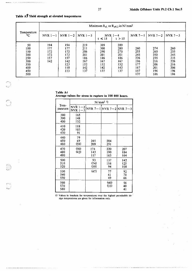
'<-
'"''
27 Mobile Offshore Units Pt.2 Ch.1 Sec.5
Table A1' Yield strength at elevated temperatures
Temperature oc
50 100 150 200 250 300 350 400 450 500
Minimum ReL or Rp(l,2 in NI mm2
NVRl-1 NVR 1-2 NVRl-3 NVR 1-4 NVR 7-1
194 177 172 172 157 142
t .;; 15 t > 15
194 219 309 289 177 211 300 280 172 206 290 270 172 201 201 201 157 186 186 186 142 167 167 167 123 152 152 152 118 142 142 142 113 137 137 137
Table A4 Average values for stress to rupture in 100 000 hours.
N/mm2 1) Tern- NVR 1-2 perature NVR 1-3 NVR 7-1 NVR 7-2 NVR 7-3
380 165 390 148 400 132
410 118 420 103 430 91
440 79 450 69 245 284 460 (59) 209 251 470 (50) 174 220 207 480 (42) 143 190 184 490 117 163 164 500 93 137 142 510 (74) 116 125 520 (59) 94 108 530 (47) 77 92 540 61 78 550 49 66 560 (40) 56 570 (33) 48 580 41
I) Values in brackets for temperatures over the highest permissible de· sign temperatures are given for information only.
260 255 245 226 196 177 167 157 137
NVR 7-2 NVR 7-3
274 260 260 255 250 245 235 235 216 226 206 216 201 206 196 196 186 186
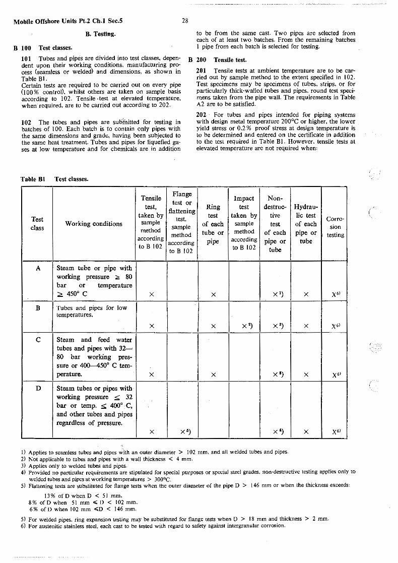
Mobile Offshore Units Pt.2 Ch.I Sec.5
B. Testing.
B 100 Test classes.
28
to be from the same cast. Two pipes are selected from each of at least two batches. From the remaining batches l pipe from each batch is selected for testing.
101 Tubes and pipes are divided into test classes, dependent upon their working conditions, manufacturing process (seamless or welded) and dimensions, as shown in Table BJ.
B 200 Tensile test.
Certain tests are required to be carried out on every pipe (I 00 % controil. whilst others are taken on sample basis according to 102. Tensile -test at elevated temperature, when· required. are to be carried out according to 202.
102 The tubes and pipes are subfnitted for testing in batches of 100. Each batch is to contain only pipes with the same dimensions and grade, having been subjected to the same heat treatment. Tubes and pipes for liquefied gases at low temperature and for chemicals are in addition
Table Bl Test classes.
Tensile Flange
test, test or
flattening Test
taken by test.
class Working conditions sample
sample method
method according according
to B 102 to B 102
A Steam tube or pipe with working pressure :.. 80 bar or temperature :<: 450° c x
B Tubes and pipes for low temperatures,
x
c Steam and feed water tubes and pipes with 32-80 bar working pres-sure or 400-450° C tern-perature. x
D Steam tubes or pipes with working pressure ::;; 32 bar or temp. ::;;; 400° C, and other tubes and pipes regardless of pressure.
x X')
201 Tensile tests at ambient temperature are to be carried out by sample method to the extent specified in l 02. Test specimens may be specimens of tubes, strips, or for particularly thick-walled tubes and pipes, round test specimens taken from the pipe wall. The requirements in Table A2 are to be satisfied.
202 For tubes and pipes intended for piping systems with design metal temperature 200°C or higher, the lower yield stress or 0,2 % proof stress at design temperature is to be determined and entered on the certificate in addition to the test required in Table Bl. However. tensile tests at elevated temperature are not required when:
Impact Non-Ring test destruc- Hydrau-test taken by tive lie test Corra-
of each sample test of each sion tube or method of each pipe or testing
pipe according pipe or tube to B 1.02 tube
x x ') x X"
x x ') x ') x X'l
x x ') x X'l
x ') x X"
1) Applies to seamless tubes and pipes with an outer diameter > I 02 mm. and all welded tubes and pipes. 2) Not applicable to tubes and pipes with a wall thickness < 4 mm. 3) Applies only to welded tubes and pipes. 4) Provided no particular requirements are stipulated for special purposes or special steel grades. non-destructive testing applies only to
welded tubes and pipes at working temperatures > 300°C. 5) Flattening tests are substituted for flange tests when the outer diameter of the pipe D > 146 mm or when the thickness exceeds:
13% of D when D < 51 mm, 8% ofD when 51 mm ~ D < 102 mm. 6% ofD when 102 mm .;o < 146 mm.
5) For welded pipes. ring expansion testing may be substituted for flange tests when D > 18 mm and thickness > 2 mm. 6) For austenitic stainless steel, each cast to be tested with regard to safety against intergranular corrosion.
1'._
(

, ..
,.
<~·
,,.. ..
"""···
the tensile strength determined at ambient temperature is at least 40 NI mm2 higher than the minimum tensile strength required in Table A2. This applies only to tubes and pipes made from carbon and carbon-manganese steels. the manufacturer submits comprehensive test data from the running production, verifying that the requirements specified in Table A3 for the steel grades and temperatures in question, are consistently fulfilled. the required lower yield stress or 0,2 % proof stress specified in Table A3, is higher than the average stress to rupture given in Table A4 for the design metal temperature in question.
203 When elevated temperature tensile test is required, one test is to be taken from each cast. If the weight of finished tubes and pipes from one cast is over 30 tonnes, one additional test is to be taken for every 30 tonnes or fraction hereof. The requireme·nts in Table A3 are to be satisfied. Determination of lower yield stress or 0,2 % proof stress is to be in accordance with ISO R 783.
B 300 Flanging test.
301 The test is to be carried out by the sample method to an extent specified in Table Bl.
302 The test consists in forming, a flange in a plane perpendicular to the axis of the tube on the end of a test piece cut from a tube.
303 The test is carried out until the width of the flange measured from the inside of the tube is at least 1,5 times the thickness of the tube or 12 % of the internal diameter.
304 The test specimen is to be of length L such that after testing the remaining cylindrical portion is not less than 0,5 times the external diameter of the tube.
305 The test procedure is to be in accordance with ISO/R 165.
306 The test will be considered passed, when the formation of the flange is completed without forming cracks or other flaws.
B 400 Ring tests.
401 Ring tests are taken from both ends of each pipe or tube and are to be carried out as ring expansion tests, flattening tests or ring pulling tests, dependent upon the diameter and wall thickness of the pipe or tube, see Table B2. When the ring test is taken from a length which is subsequently cut into shorter tubes or pipes, each single tube or pipe is to be marked with the number of the ring test.
Table B2 Ring tests.
Outer diam. Wall Ring Flattening Ring of tube or thickness expanding test tensile pipe, mm mm test test
.;; 18 All x > 18 < 2 x <;;146 ;;., 2 x
> 146 .;;40 x >40 x
402 Ring expanding test consists in expanding a ring cut from an end of a tube over a conical mandrel. The ring is to be expanded over the mandrel until it breaks or until the diameter is increased by 30 % . The test specimen consists of a ring having a length of between I 0 and 16 mm. The edges may be slightly rounded with a suitable tool.
29 Mobile Offshore Units Pt.2 Ch.I Sec.5
The test procedure is to be in accordance with ISO/ R 374-1964. The test will be considered passed, and provided the fracture occurs with obvious reduction of area and ·without laps or cracks.
403 Flattening test consists of flattening a ring cut from an end of a tube until the distance between the parallel surfaces of the platens as shown in Table B3'
Table B3 Flattening test
Tensile strength Distance between N/mm2 platens
Up to and including 440 4 x wall thickness Over 440 and including 540 5 x wall thickness Over 540 and including 640 8 x wall thickness Over640 9 x wall thickness
The ring is to be cut with the ends perpendicular to the tube axis. The length is to be equal to I ,5 times the nominal internal diameter of the tube, but not less than I 0 mm nor more than I 00 mm. The test procedure is to be in accordance with ISO/ R 202-1961. For welded tubes and pipes the weld of the test specimen is to be located at an angle of 0° to the direction of pressure for one test. For· the next test, this angle is to be 90°C. The test will be considered passed, when the test specimen is unbroken and free from cracks or flaws. After flattening small cracks at the ends of the test specimen may be disregarded. If the flattening test is substituted for the flange test (see footnote 5, Table Bl), the number of tests is to be as specified for the flange test.
404 Ring tensile test consists in drawing a ring cut from an end of a tube by means of two mandrels placed inside the ring. The ring is to be pulled to fracture in a tensile machine. The ring shall have a length of about 15 mm with smoothed ends cut perpendicular to the tube axis. The diameter of the mandrels is to be at least 3 x s, where s is the nominal wall thickness of the tube. The machine speed during the tensile test is not to exceed S mm per sec. When welded tubes are subjected to tlie ring tensile test, the weld seam is to be located in the strained zone, see Fig. I. The test will be considered passed, provided the fracture occurs with obvious reduction of area without laps or cracks.
Fig. 1 Ring tensile test principle.

Mobile Offshore Units Pt.2 Ch.I Sec.5
B 500 Impact test.
501 The test is to be carried out as Charpy V-notch test by the sample method to the extent stipulated in I 02. The specimens are to be taken with their longitudinal axes parallel with the tube axis. The notch is to be cut perpendicular to the surface of the tube or pipe. The impact values are to be determined at the following testing temperatures: Grades in the NVR I -group' 5°C below the lowest design temperature. NVR 20-QQ, I0°C below the lowest design temperature or -70°C whichever is the lower. NVR 20-0, J0°C below the lowest design temperatrue or - 9 5 C whichever is the lower. NVR 20-2, -196°C. Grades in the NVR 25-group' - J 96°C. For steels in the NVR 25-group, impact testing is required .only for design temperature below - I 05°C. Standard specimens IO x IO mm square are to be used except where the wall thickness of the pipe or tube does not permit this siZe. In such cases the largest obtainable of the following specimens is to be used: IO x 7,5 mm, IO x 5 mm, IO x 2,5 mm The impact values are to fulfil the requirements stated in Table B4.
B 600 Inspection -tolerances.
601 The Surveyor should be given the opportunity to inspect and check each tube individually, both internally and externally.The surfaces of the tube or pipe are to be reasonably free from defects both internally and externally. The ends of the tubes or pipes are to be at right angles to their centre line and without burrs. Wall thickness and outer diameter to be controlled.Lamination is not accepted. Small laps, slivers, scratches or other surface defects may be removed by grinding, but the dimensions of the tubes and pipes after this process are to meet the tolerance requirements in Table B5. Repair of defects by welding is not accepted.
602 For tubes and pipes welded with filler metal, the "reinforcement is not to be higher than:
2 mm for thicknesses up to and including 8 mm, 3 mm for thicknesses over 8 mm up to and including 14 mm, 4 mm for thicknesses over 14 mm.
603 For tubes and pipes welded without ftller metal. the upset material on the outside is to be removed. The upset material on the inside is not to be higher than' 0 ,5 mm for thicknesses up to and including 8 mm, 0,8 mm for thicknesses over 8 mm up to and including 14 mm, 1.0 mm for thicknesses over 14 mm.
604 The requirements to tolerances on outer diameter and wall thicknesses are given in Table B5.
B 700 Hydraulic pressure testing.
701 All tubes and pipes are to be hydraulically tested by the manufacturer to one of the following alternative pressures, the first one of which is in no case to be exceeded:
Alternative I , NVR I and NVR 20-grades. P =
20t (0,4 R,,) D
NVR 25-grades. P _ 20t (0,8 Ro0 2)
- D
P = test pressure, in bar. D = nominal diameter, in mm. t = nominal wall thickness, in mm. Rm = specified tensile strength, in N/mm.2 Rp0.z = min. specified yield strength, in N/mm2.
30
Alternative 2,
Design pressure Test pressure P
Less than or equal to 2 X design pressure or 70 bar 70 bar whichever is the ·greater
Over 70 bar Design pressure + 70 bar
The tubes and pipes are not to show signs of leakage and are to retain their original form unchanged by tests. The Surveyor may demand that I 0 % of the tubes and pipes are re-tested in his presence. Other pressure tests, such as pneumatic test under water, may in special cases subject to argreement be substituted for the hydraulic pressure tests.
702 Subject to approval, special automatic non-destructive testing may be substituted for the pressure test prescribed in 701.
B 800 Non-destructive testing.
801 Welded tubes and pipes which are approved as equivalent to seamless pipes or tubes, are to be tested along their entire length with equipment for automatic non-destructive testing (see A 302). The equipment is to be adjusted so that any tube or pipe which has defective welds, is re-jected. . Seamless tubes and pipes may be tested with manually operated equipment.
B 900 Corrosion testing.
901 Tubes and pipes of austenitic Cr-Ni steel (NVR 25) are to be tested with regard to safety against intergranular corrosion, by the copper sulphate method according to ASTM A 262 Practice E-Copper-Copper Sulphate-Sulphurec Acid Test.
902 Wheh a test with regard to safety against selective corrosion in weld metal is required, testing according to ASTM A 262 Practice C-Nitric Acid Test is to be carried out with modifications according to the following,
the test is to be carried out on specimens with weld metal. the surface of the weld metal is to cover at least 25 % of the total surface of the test specimen. the total surface of the test specimen is to be at least 600 mm2. grinding of the test specimen is permitted on cut surfaces only.
The corrosion testing is to consist of at least three test periods of 48 hours each. The results. w,hich express the corrosion rate, are to be indicated as g/ m2h for each period. The corrosion rate for each test period is not to exceed 1.0 g/m2h.
B 1000 Re-testing.
1001 If one or more of the sample method tests prove unsatisfactory, the tube or pipe in question is rejected, and twice as many new pipes or tubes of the batch in question are to be selected for testing. All these tests are to show satisfactory results - if not, the whole batch is rejected. A renewed heat treatment of the batch and subsequent retesting of the material will be accepted. The tests are to be executed in the same way as for the first time. All results are to be satisfactory. if not, the whole batch will be rejected.
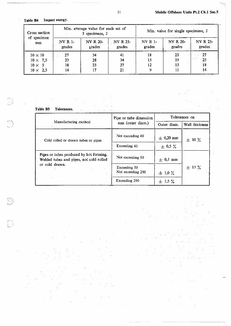
31 Mobile Offshore Units Pt.2 Ch.l Sec.5
Table B4 Impact energy.
Min. average value for each set of Min. value for single specimens, J Cross section 3 specimens, J
of specimen mm NVR 1- NVR 20- NVR 25- NVR 1- NVR 20- NVR 25-
grades grades grades grades grades grades
10 x 10 27 34 41 18 23 27 10 x 7,5 23 28 34 15 19 23 10 x 5 18 23 27 12 15 18 10 x 2,5 14 17 21 9 11 14
Table BS Tolerances.
Pipe or tube dimension Tolerances on Manufacturing method mm (outer diam.) Outer diam. j Wall thickness
Not exceeding 40 ± 0,20mm ± 10 % Cold rolled or drawn tubes or pipes
Exceeding 40 ± 0,5 %
Pipes or tubes produced by hot forming. Not exceeding 50 ± 0,5 mm Welded tubes and pipes, not cold rolled
or cold drawn. Exceeding 5 0 ± 15 % Not exceeding 200 ± 1,0 %
Exceeding 200 ± 1,5 %
''"

Mobile Offshore Units Pt.2 Ch.I Sec.6 32
SECTION 6 FORGINGS
Contents.
A. General. A 100 Scope. A 200 Manufacture. A 300 Chemical composition. A 400 Mechanical properties. A 500 Heat treatment.
B. Testing. B I 00 General. B 200 Samples for testing. B 300 Hardness testing. B 400 Ultrasonic testing. B 500 Magnetic particle testing. B 600 Sulphur print testing.
C Welding and Weld Repairs. C I 00 Welding. C 200 Repair of defects by welding. C 300 Repair welding after damages.
A. General.
A 100 Scope.
101 The requirements in this Section specify steel forgings and rolled steel bars used as a substitutes for forgings, for important ship and machinery components.
102 For forged components in structures where high toughness properties at given design temperatures are specified, special requirements to chemical and mechanical properties of the steel will be required.
A 200 Manufacture.
201 Forgings are to be manufactured from killed steel made by an approved process. The ingots are to be cast in chill moulds with big end up (normally), and with efficient feeder heads. From top and bottom end of the ingots, adequate discards are to be taken to ensure freedom from piping and harmful segregation. In addition to the top and bottom discards, surface and skin defects, which may be detrimental during the subsequent working and forming operations, are also to be removed. The conditioning is to be so performed that new, harmful defects do not arise.
202 Forgings are to be made from cast ingots according to l 0 l or from rolled semis. The pieces are to be gradually and uniformly hot worked by hammer or press forging. and thereby brought as near as possible to the finished shape. Where practicable. the pieces are to be worked so as to cause grain flow in the most favourable direction, having regard to the mode of stressing in service. Unless otherwise approved. the sectional area of any part of a forging as forged, intended for, important strength members is not to exceed:
l /3 S for carbon steel when I > d 1/2 S for alloy steel when I > d 2/ 3 S for carbon as well as alloy steel when l ..;d
where:
l = length of the part concerned (as forged), ct = diameter of the same part. S = the average cross-sectional area of the ingot or up
setted ingot, if upsetting is involved.
These requirements for the sectional area ratio (forging/ ingot) also apply when the forgings are manufactured from semis (slabs, blooms, etc.) which again are produced by rolling of ingots. The thickness of any part of disc or ring type forgings (as forged or stamped) is not to be more than one half of the length of the piece from which it was shaped.
203 For solid forged crankshafts or solid forged crank webs for built-up crankshafts. the manufacturer is to submit to the Society drawings or sketches for approval showing the shaping from ingot to the finished piece as forged.
204 For straight shafts (propeller shafts. intermediate shafts etcJ, rudder stocks, bolts and similar applications, rolled steel bars up to 250 mm diameter will be accepted as a substitute for forgings, provided a surface layer is machined off to a depth sufficient to remove surface defects and decarburized material. The cross-sectional area of the bar.as rolled is not to exceed l/3 of the cross-sectional area of the ingot. Steelmaking, casting and ingot dressing are to be carried out as required for forgings. Requirements to chemical composition, mechanical properties and heat treatment are to comply with the corresponding requirements for forgings, except that:
For rolled bars of carbon steel with diameter 65 mm and less. heat treatment may be omitted and impact test is usually not required.
205 Where flame cutting is used for shaping of forgings, the operation is to be carried out before the heat treatment (see 400). Preheating is to be employed when necessitated by chemical composition and piece dimensions. Unless otherwise agreed for machinery parts which are subjected to cyclic stress during service, the material of the flame cut surface area is to be removed to a depth of at least 6 mm by machining. If required by the Surveyor. selected areas of such machined surfaces are to be examined by magnetic-crack detection or other apProved equivalent method to ensure acceptable material.
A 300 Chemical composition.
301 Forgings, forming a part of welded construction are to have a chemical composition suitable for welding. and a composition which harmonizes with the adjacent material in the construction.
302 The chemical composition is to be determined by the steel maker for each cast. Usually, material from one sample per ladle is to be analysed. For carbon steels, the contents of the elements C. Si. Mn, P and S are to be determined. and additionally for alloy steels, the content of the alloying elements. For carbon steels. the contents of the residual elements Cr. Ni and Cu are to be determined when requested by the Surveyor. Check analysis results on material from forged parts covering the elements required for cast analyses, and in addition N and AI. are to be provided on request. The material for check analysis should preferably be taken from a tensile test specimen.
303 Steels intended for temperatures between - l 0 and + l OOCC are to comply with Table A I. The results of the ladle analysis - and check analyses, if any - are to be stated in the certificate.
(
(

,.
33 Mobile Offshore Units Pt.2 Ch.I Sec.6
Table Al Chemical composition.
Elements Carbon steels Alloy steels 4)
Cmax.1> 0,60% sP> 0,15-0,45 % Mn I) 0,40-1,40% Pmax. 0,045% 0,035 % Smax. 0,045% 0,035% N max.J> 0,011 %
I) C and Mn contents differing from those specified, may be accepted by the Society upon consideration in each case.
2) Minimum Si content for carbon deoxidized, vacuum-treated steel is 0,06%.
3) N max. 0.011 % (check analysis) applies where strong nitrogen-binders (e.g. Al, V) are Jacking. On request. the Surveyor is to be informed of the nitrogen content.
4) For alloy steels, the manufacturer is to submit to the Society for approval his specification of steel composition together with the drawings of the machinery components.
Table A2 Mechanical properties of forged carbon steels and low-alloy steels.
Tensile strength') Rm N/mm' I 430 I 490 I
Elongation') % min. } normalized or 24 (28) 22 (26) longitudinal test piece Lo = 5,65 VS (4VS respectively) hardened and tempered
Reduction of area') Z % min., } normalized or 50 (50) 45 (45) longitudinal test pic:ce
hardened and tempered
Impact energy, 3) longitudinal test piece, KU at+ 20° C J, min. average of 2 tests
Diameter :S: . 200 mm, normalized 30 25 Diameter > 200 mm, normalized 25 20 Diameter :;;: 200 mm, hardened and tempered (carbon steel or low-alloy steel) Dianieter > 200 mm, hardened and tempered (normally low-alloy steel)
I 590 I 690
19 (23) 16 (20)
19 (23) 16 (20)
40 (40) 35 (35)
50 (50) 45 (45)
22 17 17 15
27 22
25 20
Upper yield stress ReH or proof stress at Normalized: For carbon steels min. 50 % of 0,2 % elongation (Rpo,,J respectively the tensile strength and for alloy
steels min. 55 %· Hardened and tempered: As for normalized.
1) Elongation. reduction of area and impact energy which correspond to the tensile strengths between the values specified, are calculated by linear interpolation. For steel with tensile strength exceeding 690 Nlmm2, the min. values are found by linear extrapolation from the min. values at 590 NI mm2 and 69'0 NI mm2•
2) For transverse tests (circumferential and other transverse tests except radial ones), the elongation is to be min. 75 % and the reduction of area min. 70% of the longitudinal test values. For radial tests, elongation and reduction of area are to be min. 60 % and 50 % respectively, of the longitudinal test values. The figures within parentheses apply to the gauge length L = 4 $.which may be used where the dimension of the forging will not permit the use of normal gauge length. e.g. for radial tests.
3) No single test value is to be more than 5 J below the impact values specified or calculated from the specified ones. For transverse tests the impact energy is to be min. 60% of the values for longitudinal tests. However, for typical circumferential tests min. 70%. For radial tests, the impact energy is stated for information only, and should preferably be min. 50 % of the longitudinal test values.
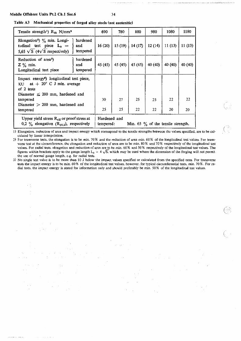
Mobile Offshore Units Pt.2 Ch.I Sec.6 34
Table A3 Mechanical properties of forged alloy steels (not austenitic)
Tensile strength') Rm N/mm' I 690 I 780 I 880 I 980 I 1080 I 1180
Elongation') % min. Longi- } hardened tudinal test piece L0 = and 16 (20) 15 (19) 14 (17) 12 (14) 11 (13) 11 (13)
5,65 vs (4VSrespectively) tempered
Reduction of area 2) } hardened Z % min. and 45 (45) 45 (45) 45 (45) 40 (40) 40 (40) 40 (40) Longitudinal test piece tempered
Impact energy•) longitudinal test piece, KU at + 20° C J min. average of 2 tests Diameter S: 200 mm, hardened and tempered 30 27 25 25 22 22 Diameter > 200 mm, hardened and tempered 25 25 22 22 20 20
Upper yield stress R,H or proof stress at Hardened and 0,2 % elongation (Rpo,2), respectively tempered: Min. 65 % of the tensile strength.
J) Elongation, reduction of area and impact energy which correspond to the tensile strengths between the values specified, are to be calculated by linear interpolation.
2) For transverse tests, the elongation is to be min. 70 % and the reduction of area min. 60 % of the longitudinal test values. For transverse test at the-circumference, the elongation and reduction of area are to be min. 80% and 70% respectively of the longitudinal test values. For radial tests, elongation and reduction of area are to be min. 60 % and 50 % respectively of the longitudinal test values. The figures within brackets apply to the gauge length Lo = 4 y'S, which may be used where the dimension of the forging will not permit the use of normal gauge length, e.g. for radial tests.
3) No single test value is to be more than IO J below the impact values specified or calculated from the specified ones. For transverse tests the impact energy is to be min. 60 % of the longitudinal test values. however, for typical circumferential tests, min. 70 % . For radial tests, the impact energy is stated for information only and should preferably be min. 50 % of the longitudinal test values.
(

35 Mobile Offshore Units Pt.2 Ch.1 Sec.6
Table A4 Test temperature and heat treatment for low temperature application.
Lowest permissible Impact test temperature Steel quality Heat treatment design temperature oc oc
C/Mn-steel Normalized') - 55 5° C below design tempera-ture, but not higher than
-20°C2)
2 1/4 % Ni-steel - 654) 10° C below design tempe-
rature, or - 70° C, which-ever is the lower
Normalized 3 1/2 % Ni-steel or - 904
) 10° C below design tempe-normalized rature, or - 95° C, which-
and ever is the lower
5 % Ni-steel tempered')
-105 10° C below design tempe-rature, or -110° c,
whichever is the lower
9 % Ni-steel Double normalized and - 165 - 196 tempered or quenched and
tempered
Austenitic Solution treated - 196 - 1963)
Cr/Ni-steel
I) Quench~d and tempered steel may also be used. In such cases the requirements to the mechanical properties are to be approved by the Society.
2) For design temperature 0°C and above the following apply: - Thickness: t ~ 20 mm, test temperature 0°C
20 mm < t < 30 mm. test temperature - 20°C. 3) Impact testing is required only for design temperatures below - I 05°C. 4) For forgings in pipe systems a lower design temperature may be accepted after consideration by the Society in eaeh separate case.

Mobile Offshore Units Pt.2 Ch.I Sec.6
304 For steels intended for temperatures above 100° C,particulars of the chemical composition are to be submitted to the Society for approval in each case.
305 For forgings intended for design temperatures below - 10° C and for liquefied gas systems the following apply,
for carbon and carbon-manganese steels. the content of sulphur and phosphorus is not to exceed 0.035 % each, and the content of nickel is not to exceed 0.80%. . the chemical composition of alloy steels is to be according to the requirements given for the same type of rolled steel. the content .of residual elements is not to exceed the following, er, 0.20 % . Cu' 0,35 % , Mo' 0,08 % . carbon and carbon-manganese steel and steels in the NV 20-group are to be fine grain treated with Al. Subject to agreement with the Society, other grain refining elements may be used. Fine grain treatment is not required for design temperature 0° C and higher when the material thicknesses are 20 mm or less. The following content is not to be exceeded: Al sol., 0,08%, Nb' 0,05%. v, 0.10%. for forgings on which welding is not performed, deviating specifications for chemical composition may be forwarded to the Society for consideration.
A 400 Mechanical properties.
401 The steels for forgings are divided into two tensile strength ranges. 430-690 Nlmm2 and 690-1.180 Nlmm2 respectively. The Tables A2 and A3 show the interdependency of the tensile strength and the specified minimum values at ambient temperature for yield point (or proof stress at 0,2 % elongation. Rp0,2). elongation after fracture, reduction of area and impact energy anywhere within the ranges. For forgings with tensile strength up to 590 NI mm2, the variation in any one forging is not to exceed 60 NI mm2 for tensile test specimens taken from each end of the forging. For forgings with tensile strength exceeding 590 NI mm2. the test results are not to vary by more than 100 NI mm2 for any forging. The test results are to be stated in the certificate. For steels intended for elevated temperatures, information about minimum yield stress, or average values of stress to rupture, at design temperature may be required. In special cases information about fatigue strength values will also be asked for.
402 For components for reduction gears which are finally to be surface hardened or case hardened all relevant data are to be submitted for consideration.
403 For forgings intended for design temperature below - 10° C and for liquefied gas systems. the following apply,
carbon and carbon-manganese steels are to comply with the requirements given in Section 3 Table 82 regarding yield stress, elongations and reduction of area. alloy steels are to comply with the requirements given for the same type of rolled steel regarding tensile strength, yield stress. elongation and reduction of area, see Section 3 Table C2. all steels are to be impact tested, using a V-notch (KV) test specimen at temperatures stipulated in Table A4. The test specimens are to be taken with their axes parallel to the longitudinal direction of the forging. When using specimens of l 0 x I 0 mm crosssection, the average value from 3 tests is not to be less than 4U. One single test may give a value below the required average. but not lower than 271.
36
the requirements in Table A4 apply to thicknesses up to 30 mm for carbon- and carbon-manganese steels. and 20 mm for alloy steels. Requirements for greater thicknesses will be considered in each particular case. for forgings with large dimensions, or with specially stressed working conditions. the Society may in each case stipulate special requirements to impact strength, non-destructive inspections and other relevant tests. for forgings on which welding is not performed, deviating specifications for impact energy may be forwarded to the Society for consideration.
A 500 Heat treatment.
501 All forgings are to be properly heat-treated. The heat treatment is to take place after the forging work is completed. If a forging is subsequently heated for any further forging work. it is again to be heat-treated. The heat treatment is to be carried out in a furnace which permits the whole forging to be uniformly heated throughout to the required temperature. The furnace is to have adequate temperature control. Where important forgings are heat-treated, the Society may require the furnace to be equipped with recording instruments for control. The manufacturer is to supply a certificate which, besides stating that heat treatment has been carried out, also submits full details of the treatment. If a forging after heat treatment and testing fails to meet the specified requirements, a further heat treatment with subsequent testing will be accepted. No forging is to be completely reheat-treated more than twice without the consent of the Society.
502 Forgings intended for design temperature below - 10° C and for liquefied gas systems are to be heat treated according to the requirements given in Table A4.
B. Testing.
B 100 General.
101 Testing of forged materials always includes testing of mechanical properties at ambient temperature. The Society may require that mechanical properties at elevated temperature, and possibly also fatigue properties, are determined. If so. the test methods are subject to approval. In certain specified cases the materials are also to be tested for hardness. cracks and other surface defects as well for non-metallic inclusions. Existence of crack and surface defects is to be traced by magnetic-particle testing or other approved method. The existence and distribution of nonmetallic inclusions is to be ascertained by sulphur prints and/ or ultrasonic testing, and possibly also by magneticparticle testing. If the following test regulations do not clearly specify how and to what extent a component is to be tested. The Society will decide the type and extent of testing to be carried out.
B 200 Samples for testing.
201 Test samples are to be taken from a part of the forging with cross-sectional area at least equal to that of the main body of the forging. The test material is not to be detached from the forging until the final heat treatment has been completed. The test specimens are normally to be machined from test material cut longitudinally to the direction of the principle grain flow. Where possible, the distance from the surface of the forging to the nearest surface of the specimen is to be at least l 0 % of the diameter of the thickness of the forging. Where material for testing cannot reasonably be provided from the longitudinal di-
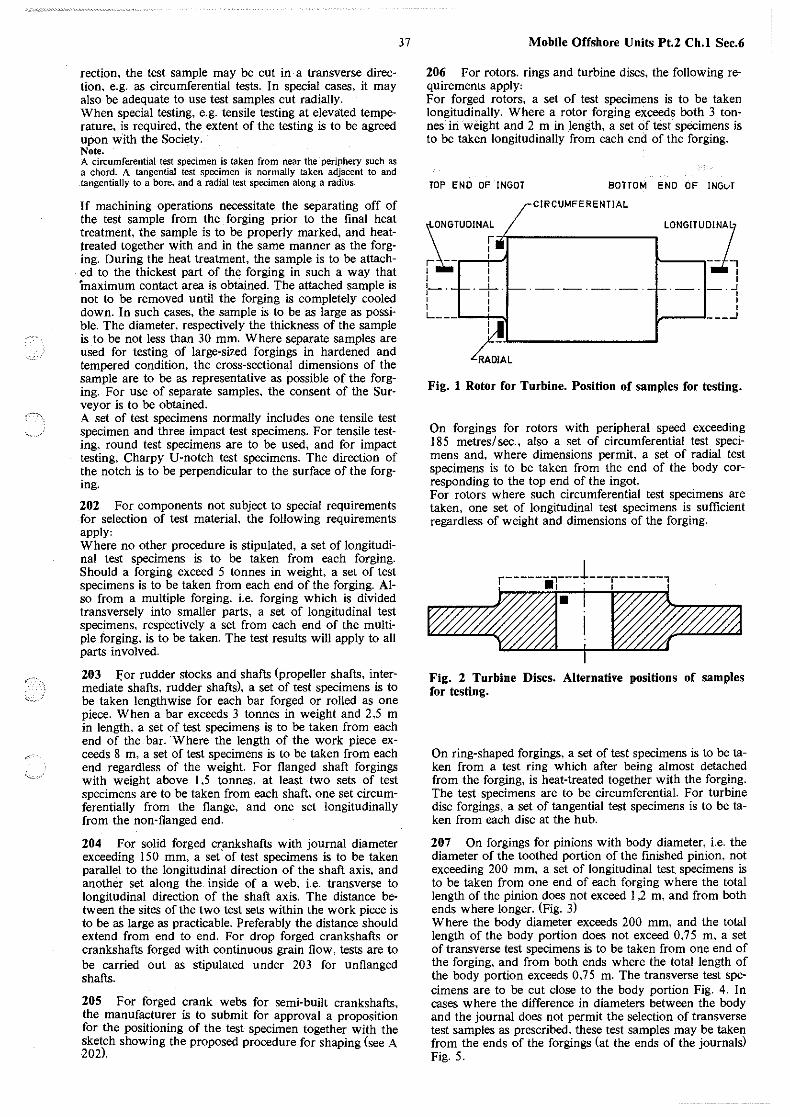
~- ..
rection, the test sample may be cut in· a transverse direction, e.g. as circumferential tests. In special cases, it may also be adequate to use test samples cut radially. When special testing, e.g. tensile testing at elevated temperature, is required, the extent of the testing is to be agreed upon with the Society. Note. A circumferential test specimen is taken from near the periphery such as a chord. A tangential test specimen is normally taken adjacent to and tangentially to a bore. and a radial test specimen along a radius.
If machining operations necessitate the separating off of the test sample from the forging prior to the final heat treatment, the sample is to be properly marked, and heattreated together with and in the same manner as the forging. During the heat treatment, the sample is to be attached to the thickest part of the forging in such a way that "maximum contact area is obtained. The attached sample is not to be removed until the forging is completely cooled down. In such cases, the sample is to be as large as possible. The diameter, respectively the thickness of the sample is to be not less than 30 mm. Where separate samples are used for testing of large-sized forgings in hardened and tempered condition, the cross-sectional dimensions of the sample are to be as representative as possible of the forging. For use of separate samples, the consent of the Surveyor is to be obtained. A set of test specimens normally includes one tensile test specimen and three impact test specimens. For tensile testing, round test specimens are to be used, and for impact testing, Charpy U-notch test specimens. The direction of the notch is to be perpendicular to the surface of the forging.
202 For components not subject to special requirements for selection of test material, the following requirements apply, Where no other procedure is stipulated, a set of longitudinal test specimens is to be taken from each forging. Should a forging exceed 5 tonnes in weight, a set of test specimens is to be taken from each end of the forging. Also from a multiple forging, i.e. forging which is divided transversely into smaller parts, a set of longitudinal test specimens, respectively a set from each end of the multiple forging, is to be taken. The test results will apply to all parts involved.
203 J:or rudder stocks and shafts (propeller shafts, intermediate shafts, rudder shafts), a set of test specimens is to be taken lengthwise for each bar forged or rolled as one piece. When a bar exceeds 3 tonnes in weight and 2,5 m in length, a set of test specimens is to be taken from each end of the bar. Where the length of the work piece exceeds 8 m, a set of test specimens is to be taken from each end regardless of the weight. For flanged shaft forgings with weight above 1,5 tonnes, at least ·two sets of test specimens are to be taken from each shaft, one set circumferentially from the flange, and one set longitudinally from the non-flanged end.
204 For solid forged cr.ankshafts with journal diameter exceeding 150 mm, a set of test specimens is to be taken parallel to the longitudinal direction of the shaft axis, and another set along the inside of a web, i.e. transverse to longitudinal direction of the shaft axis. The distance between the sites of the two test sets within the work piece is to be as large as practicable. Preferably the distance should extend from end to end. For drop forged crankshafts or crankshafts forged with continuous grain flow, tests are to be carried out as stipulated under 203 for unflanged shafts.
205 For forged crank webs for semi-built crankshafts, the manufacturer is to submit for approval a proposition for the positioning of the test specimen together with the sketch showing the proposed procedure for shaping (see A 202).
37 Mobile Offshore Units Pt.2 Ch.I Sec.6
206 For rotors. rings and turbine discs, the following requirements apply, For forged rotors, a set of test specimens is to be taken longitudinally. Where a rotor forging exceeds both 3 tonnes in weight and 2 m in length, a set of test specimens is to be taken longitudinally from each end of the forging.
TOP ENO OF INGOT BOTTOM END OF INGvT
CIRCUMFERENTIAL
\ONGTUOINAr. I LONGITU:l~A~
i~ I ~-I I I I l_._L..._ . ......l__.L..__._. _______ f..--.-. _ . ..J I I I I I I I I I L-- ---'
~~L~~~~~~~~~--'
Fig. I Rotor for Turbine. Position of samples for testing.
On forgings for rotors with peripheral speed exceeding 185 metres/sec., also a set of circumferential test specimens and, where dimensions permit, a set of radial test specimens is to be taken from the end of the body corresponding to the top end of the ingot. For rotors where such circumferential test specimens are taken, one set of longitudinal test specimens is sufficient regardless of weight and dimensions of the forging.
r------~---1---r------,
-el"i~ Fig. 2 Turbine Discs. Alternative positions of samples for testing.
On ring-shaped forgings, a set of test specimens is to be taken from a test ring which after being almost detached from the forging, is heat-treated together with the forging. The test specimens are to be circumferential. For turbine disc forgings, a set of tangential test specimens is to be taken from each disc at the hub.
207 On forgings for pinions with body diameter, i.e. the diameter of the toothed portion of the finished pinion, not exceeding 200 mm, a set of longitudinal test specimens is to be taken from one end of each forging where the total length of the pinion does not exceed 1,2 m, and from both ends where longer. (Fig. 3) Where the body diameter exceeds 200 mm, and the total length of the body portion does not exceed 0, 7 5 m, a set of transverse test specimens is to be taken from one end of the forging, and from both ends where the total length of the body portion exceeds 0, 7 5 m. The transverse test specimens are to be cut close to the body portion Fig. 4. In cases where the difference in diameters between the body and the journal does not permit the selection of transverse test samples as prescribed, these test samples may be taken from the ends of the forgings (at the ends of the journals) Fig. 5.
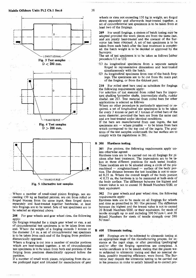
Mobile Offshore Units Pt.2 Ch.I Sec.6
\---r---i lo
1-· I
c~HH-Fig. 3 Test samples
D < 200 mm.
~ j-----, I I
• _J I I I __ _J
·r------.------1 --;
I I I I L_..:...
r.-- • 1 I I I I I I r-· I I I I I I L I J\
D
TRANSVERSE
Fig. 4 Test samples D > 200 mm.
TRANSVERSE
I I I I
I I I . --r-. I I I
I I I
. I __ _J
~ ' --, I I I I I I
. -i I I I I I I
~ •-c::-..J >
Fig. 5 Alternative test samples
Where a number of small-sized pinion forgings. not exceeding 150 kg as finished pinions, are cut from rolled or forged blooms from the same ingot, then forged down separately and heat-treated together batchwise, at least two forgings are to be tested. Sets of test specimens are to be selected as stipulated above.
208 For gear wheels and gear wheel rims, the following apply1 On forgings intended for a single gear wheel or rim, a set of circumferential test specimens is to be taken from one end. Where the weight of a forging exceeds 3 tonnes or the diameter 2,4 m, a set of circumferential test specimen is to be taken from each end of the forging from positions diametrically opposed. Where a forging is cut into a number of smaller portions which are heat-treated together, a set of circumferential test specimens is to be taken from both end portions of the forging from positions diametrically opposed before the partition. If a number of small work pieces, originating from the same preforged ingot and intended for manufacture of gear
38
wheels or rims not exceeding 150 kg in weight, are forged down separately and afterwards heat-treated together, a set of circumferential test specimens is to be taken. from at least two of the forgings.
209 For small forgings, a system of batch testing may be adopted provided the work pieces are from the same cast, and are jointly heat-treated and the consent of the Surveyor has been obtained. A set of test specimens is to be taken from each batch after the heat treatment is completed. the batch weight is to be decided or approved by the Surveyor. The set of test specimens is to be taken as follows [either procedure ( 1) or (2)J
( 1) As longitudinal specimens from a separate sample forged to representative dimensions and heat-treated simultaneously with the batch.
(2) As longitudinal specimens from one of the batch forgings. The specimens are to be cut from the main part of the forging, or from the thickest part.
210 For rolled steel bars used as substitute for forgings i · the following requirements apply1 · For selection of test material from rolled bars for important shafting (propeller shafts, intermediate shafts, rudder shafts), see 203. Test material from rolled bars for other applications is selected as follows1 Where no other procedure is particularly approved or required, a set of longitudinal test specimens is to be taken for every 3 tonnes or part of 3 tonnes of rolled bars of the same diameter, provided the bars are from the same cast and are heat-treated under identical conditions. If the bars are manufactured from cast ingots, the test specimens are - where possible - to be taken from bars which correspond to the top end of the ingots. The positions of the test samples underneath the bar surface are to comply with the regulations in 20 I.
B 300 Hardness testing.
301 For pinions, the following requirements apply unless otherwise agreed: Hardness tests are to be carried out on all forgings for pinions after heat treatment. The impressions are to be taken in three different positions for each tested locality. These localities are to be situated along a circle of the premachined - roughmachined - surface of the body portion. The distance beween the test localities is not to exceed 0,25 m. Where the overall length of the body portion <;; 0, 15 m, the hardness is to be measured at both ends of the body surface. The difference between the highest and lowest value is not to exceed 30 Brinell Numbers (HB), or their equivalent.
302 For gear wheels.and gear wheel rims, the following requirements apply1 Hardness tests are to be made on all forgings for wheels and rims as prescribed in 301 (for pinions). The difference between the highest and the lowest value is not to exceed 20 Brinell Numbers (HB), or their equivalent, for steels of tensile strength up to and including 590 N/mm 2, and 30 Brinell Numbers for steels of tensile strength over 590 N/mm2.
B 400 Ultrasonic testing,
401 Forgings are to be subjected to ultrasonic testing at an appropriate stage of the manufacturing process, for instance at the ingot stage, or after prerolling (preforging) and/ or after the forging operations are completed. A works certificate is to be issued, stating that the pieces were subjected to ultrasonic testing and that no internal defects, possibly impairing efficiency, were found. The Surveyor may require the ultrasonic testing to be carried out in his presence in order to satisfy himself as to correct pro-
(
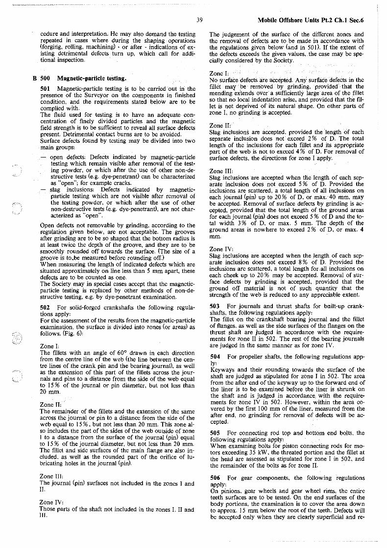
"'--~
cedure and interpretation. He may also demand the testing repeated in cases where during the shaping operations (forging, rolling, machining) - or after - indications of existing detrimental defects turn up, which call for additional inspection.
B 500 Magnetic-particle testing.
501 Magnetic-particle testing is to be carried out in the presence of the Surveyor on the components in finished condition, and the requirements stated belo'w are to be complied with. The fluid used for testing is to have an adequate concentration of finely divided particles and the magnetic field strength is to be sufficient to reveal all surface defects present. Detrimental contact burns are to be avoided. Surface defects found by testing may be divided into two main groups:
open defects' Defects indicated by magnetic-particle testing which remain visible after removal of the testing powder, or which after the use of other non-destructive tests (e.g. dye-penetrantl can be characterized as "open"; for example cracks. slag inclusions' Defects indicated by magneticparticle testing which are not visible after removal of the testing powder, or which after the use of other non-destructive tests (e.g. dye-penetrantl, are not characterized as "open".
Open defects not removable by grinding, according to the regulation given below, are not acceptable. The grooves after grinding are to be so shaped that the bottom radius is at least twice the depth of the groove, and they are to be smoothly rounded off towards the surface. (The size of a groove is to .. be measured before rounding off.) When measuring the length of indicated defects which are situated approximately on line less than 5 mm apart, these defects are to be counted as one. The Society may in special cases accept that the magneticparticle testing is replaced by other methods of non-destructive testing, e.g. by dye-penetrant examination.
502 For solid-forged crankshafts the following regulations apply' For the assessment of the results from the magnetic-particle examination, the surface is divided into zones (or areas) as follows. (Fig. 6),
Zone J, The fillets with an angle of 60° drawn in each direction from the centre line of the web (the line between the centre lines of the crank pin and the bearing journal), as well as the extension of this part of the ftllets across the journals and pins to a distance from the side of the web equal to 15 % of the journal or pin diameter, but not less than 20 mm.
Zone n, The remainder of the fillets and the extension of the same across the journal or pin to a distance from the side of the web equal to 15 % , but not less than 20 mm. This zone also includes the part of the sides of the web outside of zone I to a distance from the surface of the journal (pin) equal to 15 % of the journal diameter, but not less than 20 mm. The fillet and side surfaces of the main flange are also included. as well as the rounded part of the orifice of lubricating holes in the journal (pin).
Zone m, The journal (pin) surfaces not included in the zones I and II.
Zone JV, Those parts of the shaft not included in the zones I, II and III.
39 Mobile Offshore Units Pt.2 Ch.1 Sec.6
The judgement of the surface of the different zones and the removal of defects are to be made in accordance with the regulations given below (and in 501 ). If the extent of the defects exceeds the given values, the case may be specially considered by the Society.
Zone J, No surface defects are accepted. Any surface defects in the fillet may be removed by grinding, provided that the mending extends over a sufficiently large area of the fillet so that no local indentation arise, and provided that the fillet is not deprived of its natural shape. On other parts of zone I. no grinding is accepted.
Zone n, Slag inclusions are accepted, provided the length of each separate inclusion does not exceed 2 % of D. The total length of the inclusions for each fillet and its appropriate part of the web is not to exceed 4 % of D. For removal of surface defects, the directions for zone I apply.
Zone III' Slag inclusions are accepted when the length of each separate inclusion does not exceed 5 % of D. Provided the inclusions are scattered, a total length of all inclusions on each journal (pinl up to 20 % of D, or max. 40 mm, may be accepted. Removal of surface defects by grinding is accepted, provided that the total length of the ground areas for each journal (pin) does not exceed 5 % of D and the total width 3 % of D, or max. 5 mm. The depth of the ground areas is nowhere to exceed 2 % of D, or max. 4 mm.
Zone JV, Slag inclusions are accepted when the length of each separate inclusion does not exceed 8 % of D. Provided the inclusions are scattered, a total length for.all inclusions on each cheek up to 20 % may be accepted. Removal of surface defects by grinding is accepted, provided that the ground off material is not of such quantity that the strength of the web is reduced to any appreciable extent.
503 For journals and thrust shafts for built-up crankshafts, the following regulations apply, The fillet on the crankshaft bearing journal and the fillet of flanges, as well as the side surfaces of the flanges on the thrust shaft are judged in accordance with the requirements for zone II in 502. The rest of the bearing journals are judged in the same manner as for zone IV.
504 For propeller shafts, the following regulations apply, Keyways and their rounding towards the surface of the shaft are judged as stipulated for zone I in 502. The area from the after end of the keyway up to the forward end of the liner is to be examined before the liner is shrunk on the shaft and is judged in accordance, with the requirements for zone IV in 502. However, within the area covered by the first 100 mm of the liner, measured from the after end, no grinding for removal of defects will be accepted.
505 For connecting rod top and bottom end bolts, the following regulations apply: When examining bolts for piston connecting rods for motors exceeding 3 5 kW, the threated portion and the fillet at the head are assessed as stipulated for zone I in 502, and the remainder of the bolts as for zone II.
506 For gear components, the following regulations apply, On pinions, gear wheels and gear wheel rims, the entire teeth surfaces are to be tested. On the end surfaces of the body portions, the examination is to cover the area down to approx. 15 mm below the root of the teeth. Defects will be accepted only when they are clearly superficial and re-
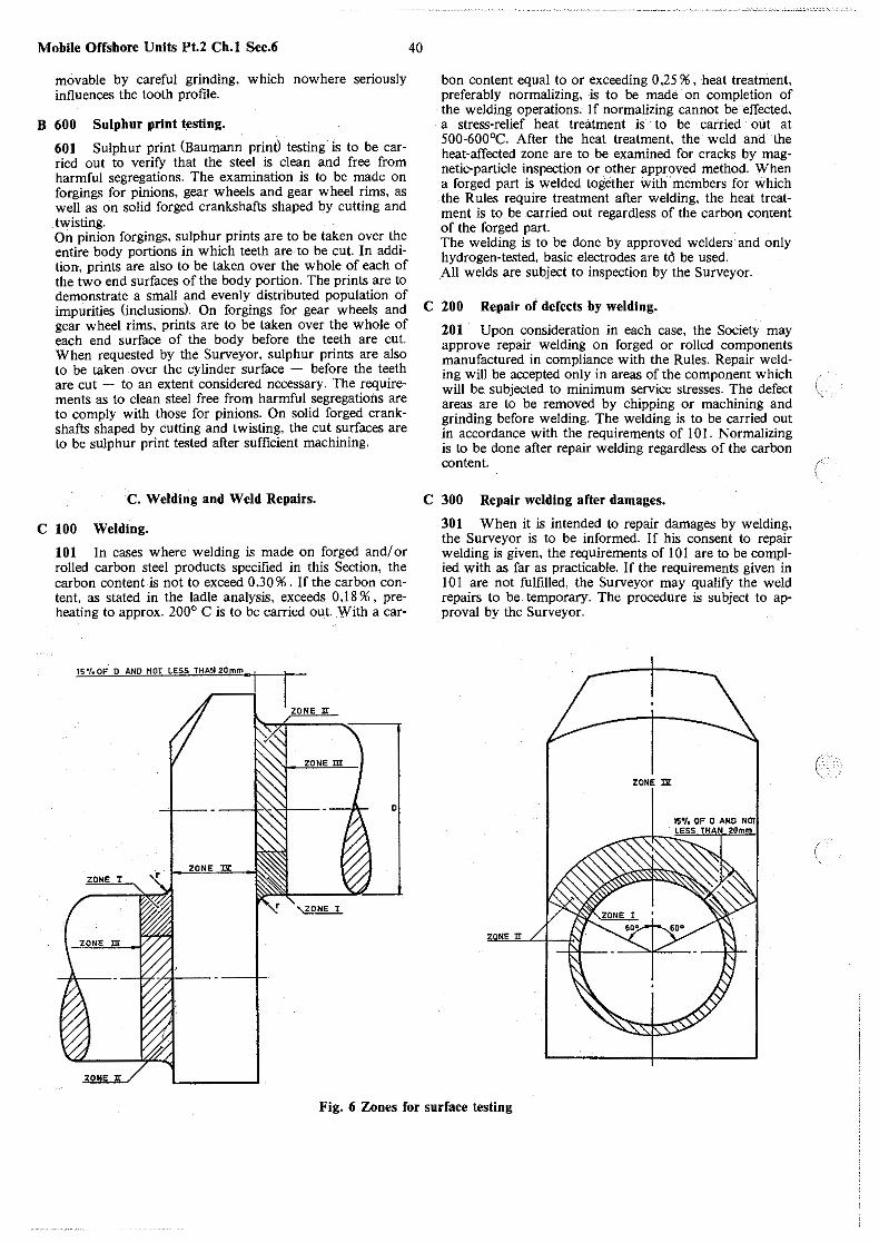
Mobile Offshore Units Pt.2 Ch.I Sec.6
movable by careful grinding, which nowhere seriously influences the tooth profile.
B 600 Sulphur print testing.
601 Sulphur print (Baumann print) testing is to be carried out to verify that the steel is clean and free from harmful segregations. The examination is to be made on forgings for pinions, gear wheels and gear wheel rims, as well as on solid forged crankshafts shaped by cutting and twisting. On pinion forgings, sulphur prints are to be taken over the entire body portions in which teeth are to be cut. In addiM tion-, prints are also to be taken over the whole of each of the two end surfaces of the body portion. The prints are to demonstrate a small and evenly distributed population of impurities (inclusions). On forgings for gear wheels and gear wheel rims, prints are to be taken over the whole of each end surface of the body before the teeth are cut. When requested by the Surveyor, sulphur prints are also to be taken over the cylinder surface - before the teeth are cut - to an extent considered necessary. The requireM ments as to clean steel free from harmful segregations are to comply with those for pinions. On solid forged crankshafts shaped by cutting and twisting, the cut surfaces are to be sulphur print tested after sufficient machining.
C. Welding and Weld Repairs.
C 100 Welding.
101 In cases where welding is made on forged and/ or rolled carbon steel products specified in this Section, the carbon content is not to exceed 0,30 % . If the carbon content, as stated in the ladle analysis, exceeds 0,18 % , preheating to approx. 200° C is to be carried out. With a car-
15"/.0F o AND NOT LESS THAN20mm
1
t ZONE II
0
ZONE lJt ZONE I
40
bon content equal to or exceeding 0,25 % , heat treatment, preferably normalizing, is to be made on completion of the welding operations. If normalizing cannot be effected, a stress-relief heat treatment is to be carried out at 500-600°C. After the heat treatment, the weld and the heat-affected zone are to be examined for cracks by magnetic-particle inspection or other approved method. When a forged part is welded together with members for which the Rules require treatment after welding, the heat treatment is to be carried out regardless of the carbon content of the forged part. The welding is to be done by approved welders and only hydrogen-tested, basic electrodes are to be used. All welds are subject to inspection by the Surveyor.
C 200 Repair of defects by welding.
201 Upon consideration in each case, the Society may approve repair welding on forged or rolled components manufactured in compliance with the Rules. Repair welding will be accepted only in areas of the component which will be subjected to minimum service stresses. The defect areas are to be removed by chipping or machining and grinding before welding. The welding is to be carried out in accordance with the requirements of 101. Normalizing is to be done after repair welding regardless of the carbon content.
C 300 Repair welding after damages.
301 When it is intended to repair damages by welding, the Surveyor is to be informed. If his consent to repair welding is given, the requirements of I 0 I are to be complied with as far as practicable. If the requirements given in I 0 I are not fulfilled, the Surveyor may qualify the weld repairs to be temporary. The procedure is subject to approval by the Surveyor.
ZONE DI:
Fig. 6 Zones for surface testing
c
~-. ,
•··
-."-" .. ·
41 Mobile Offshore Units Pt.2 Ch.I Sec.7
SECTION 7 BARS FOR CHAIN CABLES
Contents.
A General. A 100 Scope. A 200 Steel grades. A 300 Chemical composition. A 400 Mechanical properties. A 500 Heat treatment.
B Testing. B I 00 Number of tests. B 200 Impact testing.
C Illentification of Materials. C I 00 Branding.
A. General.
A 100 Scopes.
101 The requirements in this Section specify steel intended for chain cable links and accessories (shackels. swivels etc.)
A 200 Steel grades.
201 Four steel grades are specified'
NV K I. NV K 2. NV K 3. NV K 4.
A 300 Chemical composition.
301 The chemical composition of ladle samples is to comply with the approved specification. For the steel grades NVK I. NVK 2 and NVK 3 the overhall limits given in Table Al apply.
A 400 Mechanical properties.
401 The mechanical properties are to comply with the requirements given in Table A I .
A 500 Heat treatment.
501 The requirements to heat treatment given in Table Al apply to finished chain cable and accessories. Material intended for such application may, after agreement with the Society. be delivered without the heat treatment stipulated.
B. Testing.
B 100 Number of tests.
101 One set of tests (I tensile and 3 impact test specimens) is to be taken for every 40 ton or fraction thereof of bar material from the same cast. The tests are to be taken from the bar of the largest diameter. Test material from bars is to be heat-treated in full diameter and in a manner simulating the treatment applied to the finished cable.
B 200 Impact testing.
201 The impact test specimens are to be cut as shown in Fig. I.
The tests are to satisfy the requirements stated in Table Al.
C. Identification of Materials.
C 100 Branding.
101 Each bar is to be stamped with the steel grade designation according to Table A J. fn addition, each grade is to be branded with the following colours:
NV KI - white NVK2-red NV K 3 - green NV K 4 - blue.
APPROX. 1/3r
Fig. l Position of impact test specimen.
NOTCH
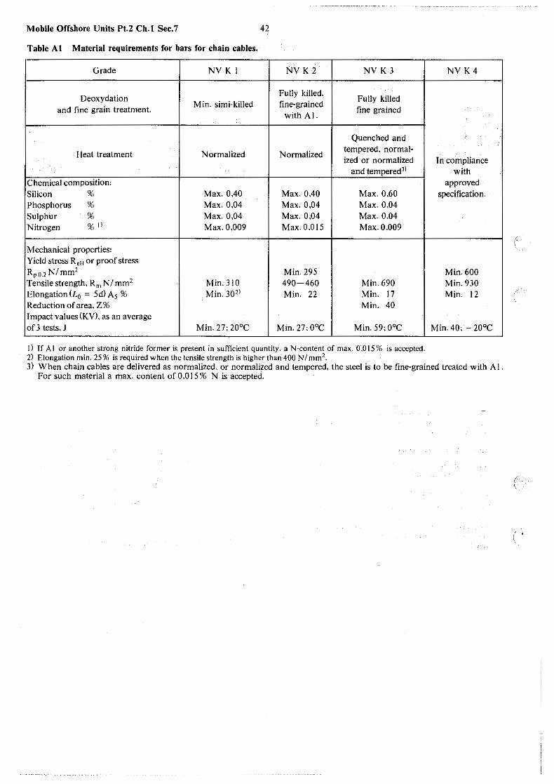
Mobile Offshore Units Pt.2 Ch.I Sec.7 42
Table A I Material requirements for bars for chain cables.
Grade NV KI NV K 2 NV K 3 NV K4
Deoxydation Fully killed.
Fully killed and fine grain treatment.
Min. simi-killed fine-grained fine grained
with Al.
Quenched and
Heat treatment Normalized Normalized tempered, normal-ized or normalized In compliance
and temperect31 with Chemical composition: approved Silicon % Max. 0.40 Max. 0.40 Max. 0.60 specification. Phosphorus % Max. 0.04 Max. 0.04 Max. 0,04 Sulphur % Max. 0.04 Max. 0.04 Max. 0.04 Nitrogen % J) Max. 0.009 Max. 0,0!5 Max. 0.009
Mechanical properties: Yield stress RcH or proof stress R, 0 ,, N/mm2 Min. 295 Min. 600 Tensile strength. Rm N/ mm2 Min. 310 490-460 Min. 690 Min. 930 Elongation (L0 ~ 5d) A5 % Min. 302l Min. 22 Min. 17 Min. 12 Reduction of area. Z % Min. 40 Impact values (KV), as an average of 3 tests. J Min. 27; 20°C Min. 27:0°C Min. 59:0°C Min. 40; - 20°C
I) If Al or another strong nitride former is present in sufficient quantity, a N-content of max. 0-.015% is accepted. 2) Elongation min. 25 % is required when the tensile strength is higher than 400 N/mm2•
3) When chain cables are delivered as normalized, or normalized and tempered, the steel is to be fine-grained treated with Al. For such material a max. content of0,0159() N is accepted.
(

'<· ,'
'--~· .
43 Mobile Offshore Units Pt.2 Ch.I Sec.8
SECTION 8 STEEL CASTINGS
Contents.
A. General. A 100 Scope.
B. Castings for General Application. B I 00 Steel grades. B 200 Chemical composition. B 300 Mechanical properties.
C. Castings for Boilers and Pressure Vessel. C I 00 Steel grades. C 200 Chemical composition. C 300 Mechanical properties.
D. Propeller Steel Castings. D I 00 Chemical composition. D 200 Mechanical properties.
E. Chain Cable Castings. E I 00 Specification.
F. Castings for Structural Members with Higher Tough-ness Requirements.
F I 00 Steel grades. F 200 Chemical composition. F 300 Mechanical properties.
G. Steel Castings for Design Temperatures below - I0°C and for Liquified Gas Systems.
G I 00 Chemical composition. G 200 Mechanical properties. G 300 Permissible design temperature.
H.Heat Treatment. H I 00 General. H 200 Heat treatment of carbon and carbon-manganese
steel. H 300 H 400
Heat treatment of low alloyed steel. Heat treatment of stainless steel.
I. Testing. I I 00 Test samples. I 200 Mechanical tests. I 300 Hydraulic pressure testing. I 400 Visual and non-destructive examination.
J. Rectification of Defective Castings. J I 00 Repair welding.
K. Welding of Structural Members. K I 00 Welding regulations.
A. General.
A 100 Scope.
101 The requirements in this Section specify steel castings for general and special applications.
B. Castings for General Application.
B 100 Steel grades.
101 Castings for general applications are used for components intended for general engineering purposes.
B 200 Chemical composition.
201 For steels intended for temperatures between - I 0
and + I 00°C. the .content of sulphur or phosphorus is not to exceed 0.05 % . Welded constructions which cannot be preheated, are to be made of carbon steel or carbon-manganese steel with a carbon content of max. 0,18 % .
B 300 Mechanical properties.
30 I Table BI gives the requirements for mechanical properties of carbon and carbon-manganese steel for general application. Specifications are given for two types of steel. and the castings are to be supplied to the type specified in the relevant construction Rules.
302 At ambient temperature the material is to satisfy the requirements given in Table B 1 as regards elongation, yield stress and reduction of area, bend tests and impact resistance. depending upon the tensile strength of the material in question. Ordinary cast steel or cast steel for special requirements may be used for welded constructions, depending upon the purpose for which they are to be used, but the requirements as to chemical composition given in I 0 I are to be satisfied. Where marked by a dash (-), the values obtained are to be entered on the certificate for information. Where nothing is stated, no test will be required.
303 Tensile and impact tests are normally to be carried out at room temperature (18° to 25°C).
Table Bl Mechanical properties for carbon and carbon-manganese steel castings for general application.
Type of steel Tensile Yield stress Elongation strength Rm ReH N/mm2 A 5% min.
N/mm' min.
Ordinary cast 400-430 50% of 22 steel 430-470 tensile 20
470-510 strength Rm 18 510-550 16 550-590 14
> 590 12
Cast steel 430-470 50% of 26 for special 470-510 tensile 24 requirements 510-550 strength R111 22
550-590 20 > 590 18
Type of steel Reduction Impact Bend test of area Z9i'> resistance J (19x25 mm)
min. min.1 1KU Mandrel diam. 38
mm Angle in degrees
Ordinary cast - 120 steel - 120
- 120 - 90' - 90 - 90
Cast steel 45 27 for special 40 25 requirements 40 22
35 20 35 17
I) Charpy LI-notch test carried out at room temperature.
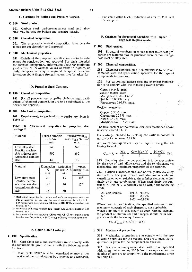
Mobile Offshore Units Pt.2 Ch. I Sec.8
C. Castings for Boilers and Pressure Vessels.
C 100 Steel grades.
101 Carbon steel, carbon-manganese steel and alloy steel may be used for boilers and pressure vessels.
C 200 Chemical composition.
20I The proposed chemical composition is to be sub-
44
For chain cable NVK3 reduction of area of 35 '!(, will be accepted.
F. Castings for Structural Members with Higher Toughness Requirements.
mitted for consideration and approval. F IOO Steel grades.
C 300 Mechanical properties.
30I Details of the proposed specification are to be submitted for consideration and approval. For steels intended for elevated temperature. information about (a) minimum yield stress, or (b) average values of stress to rupture. at design temperature, may be required. In special cases, information about fatigue strength values may be asked for.
D. Propeller Steel Castings.
D 100 Chemical composition.
IOI For all propeller and propeller blade castings, particulars of chemical composition are to be submitted to the Society for approval.
D 200 Mechanical properties.
201 Requirements to mechanical properties are given in Table DI.
Table DI Mechanical properties for propeller steel castings. I)
Material
Low-alloy steel Ferritic/ martensitic stainless steel Austenitic stainless steel
Material
Low-alloy steel I F erritic/ marten-sitic stainless steel Austenitic stainless steel I
Tensile strength R01 N/mm2
min.
540
590
440
Yield stress ReH
resp. Rp0. 2 NI mm2
min.
345
390
175
Elongation I Reduction I Impact % of area Z % energy KCU
min. min. min.
20 45 3031
18" 40 I 7"
35 I 50
I) Mechanical properties for carbon and carbon-manganese steel castings as specified for cast steel for special requirements in Table Bl. For vessels with class notation ICE (except ICE C) the elongation is to bemin.19%.
2) For vessels with class notation ICE (except ICE Cl. the elongation is to be min. 19')( •.
J) For vessels with class notation ICE (except ICE C). the impact energy is to be min. 20 Joule at ~ J0°C using a Charpy V-notch specimen.
E. Chain Cable Castings.
E 100 Specification.
101 Cast chain cable and accessories are to comply with the requirements given in Sec. 7 with the following modifications:
Chain cable NVK2 is to be normalized or may at the option of the manufacturer be quenched and tempered.
lOI Structural members for which higher toughness properties are required may be produced from carbon-manganese steel or alloy steel.
F 200 Chemical composition.
201 Chemical composition of the material is to be in accordance with the specification approved for the type of components in question.
202 For carbon-manganese steel the chemical compositioh is to comply with the following overall limits'
Carbon 0,24 % max. Silicon 0,60 % max. Manganese 050- l ,60% Sulphur 0,035 % max. Phosphorus 0,035 % max.
Residual elements:
Copper 0.30 % max. Chromium 0,25% max. Nickel 0,40 % max. Molybdenum 0.15 % max.
The total content of the residual elements mentioned above is not to exceed 0,80%.
For castings intended for welding the carbone content is normally to be below 0 ,18 % .
A max carbon equivalent may be required using the following formula:
C = C Mn Cr+Mo+V Ni+ Cu '%I oq + 6 + 5 + 15 l 0
203 For alloy steel the composition is to be appropriate for the type of steel, dimensions and the requirements on mechanical and toughness properties of the castings.
204 Carbon-manganese steel and normally also low alloy steel is to be fine grain treated with aluminium, niobium, vanadium or other suitable grain refining elements, either singly or in any combination. When used singly the content of Al. Nb or V is normally to be within the following limits:
Al. acid soluble Nb v
O.Dl5-0,08% 0,02 -0,05% 0,05 -0,10%
When used in combination, the specified m1n1mum and maximum contents of each element is not applicable. When aluminium is used singly as grain refining element, the product of aluminium and nitrogen should be in compliance with the following formula:
(% Alac.soJ.X % N) 10 5 ~ 60
F 300 Mechanical properties.
301 Mechanical properties are to comply with the specification approved for the material and are to meet the requirements given for the component in question.
302 For carbon-manganese steel with min. specified yield stress not exceeding 320 N/mm2• elongation, and reduction of area are to comply with the requirements given in Table Fl.

45
Table Fl
Specified min. 1 > Elongation AS Reduction of area. yield stress. N/ mm2 % min. W1.min.
220 26 45 240 24 40 260 22 40 300 20 35 320 18 35
I) For intermediate values of specified min. yield stress the values for elongation and reduction of area re found by interpolation.
303 For alloy steel the minimum specified yield stress is not to exceed 690 NI mm2.
304 Impact testing is to be carried out as Charpy "\!"-notch test. Minimum impact energy is to be in accordance with table F2 for the specified minimum yield stress in question. Requirements on test temperature will be given in each separate case dependent on design temperature. application category and yield stress and thickness of the materials. Generally the impact toughness is to be the same as required for rolled materials for similar application. For structural members not intended for welding and members subjected to compressive and/ or low tensile stresses, modified requirements may be considered.
Table F2 Requirements to minimum impact energy.
Min. yield stress Min. impact energy. average tl
inN/mm2 inJ
..;270 27
..;310 31
..;350 34 > 350 40
I) One individual value may be Jess than the required average value but not less than 70 % of this average value.
305 Additional toughness tests such as drop-weight test for the determination of NDT temperature and COD test may be required where found appropriate by the Society.
G. Steel Castings for Design Temperatures, below - l0°C and for Liquid Gas Systems.
G 100 Chemical composition.
101 Steel castings. forming a part of a welded construction are to have chemical composition suitable for welding and a composition which harmonizes with the adjacent material in the construction. For alloy steels the composition is to be approved by the Society.
G 200 Mechanical properties.
201 For carbon and carbon-manganese steels the requirements to yield stress. elongation and reduction of area are to be according to the requirements for cast steel for special requirements, given in Table BI. For allo_y steels the values for .tensile strength, yield stress. elongation and reduction of area are to be approved by the Society.
G 300 Permissible design temperature.
301 Lowest permissible design temperature for steel qualities to be used, for design temperature range from 0°C to - l 96°C are stipulated in Table GI.
Mobile Offshore Units Pt.2 Ch.I Sec.8
Table G l Steel castings for low temperatures.
Steel quality Heat treatment
C/Mn-steel Normalized or quenched and tempered
2 1I4 % Ni-steel Normalized.
3 I/ 2 % Ni-steel normalized and tempered or quenched and tempered
Austenitic Cr/Ni-steel Solution treated
Lowest
Steel quality permissible Impact test temp. design temp. oc
oc C/Mn-steel - 55 5°C below design
temperature, but not higher than
- 20.°C"
2 1I4 % Ni-steel - 70 10°C below design temperature.-or - 70°C, which-
ever is the lower
3 1 /2% Ni-steel -105 10°C below design temperature, or - 95°C. which-
ever is the lower
Austenitic Cr/Ni-steel - 196 - 196 11
I) Impact testing is only required for design temperatures below - !05°C.
2) for design temperature 0°C and above the following apply: - Material thickness: t o;;;;20 mm. test temperature 0°C.
t > 20 mm. test temperature - 20°C.
H. Heat Treatment.
H 100 General.
101 Heat treatment is to be in accordance with 200 to 400 and is to comply with the procedure approved for the type of casting in question.
102 Heat treatment is to be carried out in properly constucted furnaces which are efficiently maintained and have adequate means for control and recording of temperatures. The furnace dimensions are to be such as to allow the whole casting to be uniformly heated to the necessary temperature. In the case of very large castings alternative methods for heat treatment may be specially considered by the Society.
103 If a casting is locally reheated or any straightening operation is performed after the- final heat treatment, a subsequent stress relieving heat treatment may be required in order to avoid the possibility of harmful residual stresses.
H 200 Heat treatment of carbon and carbon-manganese steel.
201 Castings are to be supplied in one of the following conditions:
Fully annealed i.e. heated above the transformation range and slowly cooled. or normalized, or normalized and tempered. or quenched and tempered.
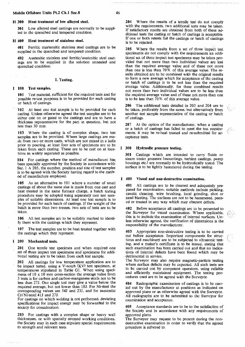
Mobile Offshore Units Pt.2 Ch.I Sec.8
H 300 Heat treatment of low alloyed steel.
301 Low alloyed steel castings are normally to be supplied in the quenched and tempered condition.
H 400 Heat treatment of stainless steel.
401 Ferritic martensitic stainless steel castings are to be supplied in the quenched and tempered condition.
402 A ustenitic stainless and ferritic/ austenitic steel castings are to be supplied in the solution annealed and quenched condition.
I. Testing.
I 100 Test samples.
101 Test material, sufficient for the required tests and for possible re-test purposes is to be provided for each casting or batch of castings.
102 At least one test sample is· to be provided for each casting. Unless otherwise agreed the test samples are to be eithe.r cast on or gated to the castings and are to have a thickness representative for the part in question. but not less than 30 mm.
103 Where the casting is of complex shape. two test samples are to be provided. Where large castings are made from two or_more casts, which are not mixed in a ladle prior to pouring, at least four sets of specimens are to be taken from each casting. These are to be cast on at locations as widely separated as possible.
104 For castings where the method of manufacure has. been specially approved by the Society in accordance with Sec. I A 205, the number, position and size of test samples is to be agreed with the Society having regard to the method of manufacture employed.
105 As an alternative to I 0 I where a number of small castings of about the same size is made from one cast and heat treated in the same furnace charge, a batch testing procedure may be adopted using separately cast test samples of suitable dimensions. At least one test sample is to be provided for each batch of castings. If the weight of the batch is more than two tonnes, two sets of tests are to be taken.
106 All test samples are to be suitably marked to identify them with the castings which they represent
107 The test samples are to be heat treated together with the castings which they represent.
I 200 Mechanical tests.
201 One tensile test specimen and when required one set of three impact test specimens and specimens for additional testing are to be taken from each test sample.
202 All castings for low temperature application are to be impact tested, using a V-notch (KV) test specimen, at temperatures stipulated in Table GL When using specimens of l 0 x I 0 mm cross-section the average value from 3 tests is for carbon and carbon-manganese steels not to be less than 27 J. One single test may give a value below the required average, but not lower than I 8J. For Ni-steel the corresponding values are 34J and 23J, and for austenitic Cr/Ni-steel 4lJ and 27J. For castings on which welding is not performed, deviating specifications for impact energy may be forwarded to the society for consideration.
203 For castings with a complex shape or heavy wall thicknesses. or with specially stressed working conditions, the Society may in each case stipulate special requirements to strength and relevant tests.
46
204 Where the results of a tensile test do not comply with the requirements, two additional tests may be taken. If satisfactory results are obtained from both of these additional tests the casting or batch of castings is acceptable. If one or both retests fail the castings or batch of castings is to be rejected.
205 Where the results from a set of three impact test speciments do· not comply with the requirements an additional set of three impact test specimens may be taken provided that not more than two individual values are less than the required average value and of these not more than one is less than 70 % of this average value. The results obtained are to be combined with the original results to form a new average which for acceptance of the casting or batch of castings is to be not less than the required average value. Additionally. for these combined results not more than two individual values are to be less than the required average value and of these not more than one is to be less than 70 % of this average value.
206 The additional tests detailed in 203 and 204 are to be taken, preferably from the same, but alternatively from another test sample representative of the casting or batch of castings.
207 At the option of the manufacturer. when a casting or a batch of castings has failed to meet the test require- / ments, it may be re-heat treated and re-submitted for ac- ( ceptance tests.
I 300 Hydraulic pressure testing.
301 Castings which are intended to carry fluids or steam under pressure (mountings. turbine castings, pump housings etc.l are normally to be hydraulically tested. The surface is to be lightly hammered during the testing.
I 400 Visual and non-destructive examination.
401 All castings are to be cleaned and adequately prepared for examination; suitable methods include pickling, caustic cleaning, wire brushing, local grinding, shot or sand blasting. The surfaces are not to be hammered. peened or treated in any way which may obscure defects.
402 Before acceptance all castings are to be presented to the Surveyor for visual examination. Where applicable, this is to include the examination of internal surfaces. Unless otherwise agreed, the verification of dimensions is the responsibility of the manufacturer.
403 Appropriate non-destructive testing is to be carried out before acceptance. Important components for struc- ( tures and machinery are to be subjected to ultrasonic testing, and a maker's certificate is to be issued. stating that such examination has been carried out and that no indications of internal defects have been found which may be detrimental in service. The Surveyor may also require magnetic-particle testing where surface defects may be expected. All such tests are to be carried out by competent operators, using reliable and efficiently maintained equipment. The testing procedures used are to be agreed with the Surveyor.
404 Radiographic examination of castings is to be carried out by the manufacturer at positions as indicated on approved plans or as otherwise agreed with the Surveyor. All radiographs are to be submitted to the Surveyor for examination and acceptance.
405 Acceptance standards are to be to the satisfaction of the Society and in accordance with any requirements of approved plans. The Surveyor may request to be present during the nondestructive examination in order to verify that the agreed procedure is adhered to.
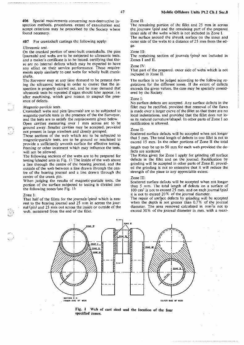
,,_,_.
47 Mobile Offshore Units Pt.2 Ch.I Sec.8
406 Special requirements concerning non-destructive inspection methods. procedures. extent of examination and accept criterions may be prescribed by the Society where found necessary.
407 For crankshaft castings the following apply,
Ultrasonic test. On the cranked portion of semi-built crankshafts. the pins (journals) and webs are to be subjected to ultrasonic tests. and a maker's certificate is to be issued. certifying that there are no internal defects which may be expected to have any effect on their service performance. These requirements apply similarly to cast webs for wholly built Crankshafts. The Surveyor may at any time demand to be present during the ultrasonic testing in order to ensure that the inspection is properly carried out and he may demand that ultrasonic tests be repeated if signs should later appear. i.e. after machining, which give reason to suspect the presence of defects.
Magnetic-particle tests. Crankshaft webs and pins (journals) are to be subjected to magnetic-particle tests in the presence of the the Surveyor. and the tests are to satisfy the requirements given below. Open cavities measuring over I mm across are to be ground away. Smaller cavities may be accepted. provided not present in large numbers and closely grouped. Those sections of the web which are to be subjected to magnetic-particle tests. are to be ground or machined to provide a sufficiently smooth surface for effective testing. Peening or other treatment which may influ.ence the tests. will not be allowed. The following sections of the webs are to be prepared for testing (shaded area in Fig. 1 ), The inside of the web above a line through the centre of the bearing journal. and the outside of the web between a line drawn through the centre of the bearing journal and a line drawn through the centre of the crank pin. When judging the results of magnetic-particle tests, the portion of the surface subjected to testing is divided into the following zones (see Fig. 1 ),
Zone 1, That half of the fillets for the journals (pins) which is nearest to the bearing journal and 25 mm in across the journal (pin) and 25 mm out across the inside or outside of the web, measured from the end of the fillet.
•
SECUON A-A llHJtER SIDE OF WEiii
Zone n, The remaining portion of the fillet and 25 mm in across the journaw (pin) and the remaining part of the .prepared inner side of the webs which is not included in Zone I. The surface around the shrunk surface on the inner and outer side of the webs to a distance of 25 mm from theedge.
Zone III: The rerfl.aining section of journals (pins) not included in Zones I and II.
Zone 1v, That part of the prepared. outer side of webs which is not included in Zone II.
The surface is to be judged according to the following regulations for the different zones. If the extent of defects exceeds the given values. the case may be specially considered by the Society.
Zone 1, No surface defects are accepted. Any surface defects in the fillet may be rectified, provided that removal of the flaws is made over a larger curve of the fillet so that there are no local indentations. and provided that the fillet does not lose its natural curvature (shape). In other parts of Zone I no rectification is allowed.
Zone n, Scattered surface defects will be accepted when not longer that 5 mm. The total length of defects in one fillet is not to exceed 15 mm. In the other portions of Zone II the total length may be up to 50 mm for each web provided the defects are scattered. The Rules given for Zone I apply for grinding off surface defects in the fillet and on the journal. Rectification by grinding will be accepted in other parts of Zone II. provided the grinding is not so extensive that it will reduce the strength of the piece to any appreciable extent.
Zone m, Scattered surface defects will be accepted when not longer than 5 mm. The total length of defects on a surface of I 00 cm2 is not to exceed 25 mm. and on each journal (pin) it is not to exceed 20 % of the journal diameter. The repair of surface defects by grinding will be accepted when the depth is not greater tlian 0.7 % of the journal diameter. The area removed calculated in mm2is not to exceed 30 96 of the journal diameter in mm. with a maxi-
ZOME ;a:
COUTER SIDE OF WEBI
Fig. 1 Web of cast steel and the location of the four specified zones.

Mobile Offshore Units Pt.2 Ch.I Sec.8
mum length of 3 % of the journal diameter. If more than one flaw is to be removed, the total area removed from one journal (pin) calculated in mm2 is not to exceed 40 W1 of the journal diameter in mm, and at the most the removal of three different defects may be accepted within an area of 100 cm2.
Zone IV: Some surface defects will be accepted when not longer than 10 mm. The total length for each web is not to exce· ed 75 mm. The rectification of surface flaws by grinding will be accepted. provided that the strength of the piece is not reduced to any appreciable extent.
408 For propellers and propeller blades the following apply: On the pressure side of propeller and propeller blade castings. the surface of the blade roots and the blades within 0,4r are to be examined by magnetic-particle methods or in the case of austenitic stainless steel by liquid-penetrant methods. The hub and the blade roots are to be subjected to ultrasonic inspection. A maker's certificate is to be issued. stating that such inspection has been carried out with satisfactory results.
409 For structural members with higher toughness requirements. the following apply:
48
Non-destructive testing is to be carried out in compliance with complete plans approved by the Society for the casting in question. Equipment, procedures, operators qualifications, extent of testing and acceptance criteria are to comply with relevant parts of the Societies Rules, Classification Notes and Programmes.
410 In the event of any casting proving defective during subsequent machining or testing it is to be repaired where possible or rejected notwithstanding any previous certification.
J. Rectification of Defective Castings.
J JOO Repair welding.
101 When unacceptable defects are found in a casting these are to be removed by machining or chipping. Flamescarfing or arc-air gouging .may also be used provided that pre-heating is employed when necessary and that the surfaces of the resulting depression are subsequently ground smooth. Complete elimination of the defective material is to be proved by adequate non-destructive testing. Shallow grooves or depression resulting from the removal of defects may, at the descretion of the Surveyor, be accepted provided that they will cause no appreciable reduction in the strength of the castings and that they are suitably smoothed and contoured by grinding.
102 Proposals to repair a defective casting by welding are to be submitted to the Surveyors for approval before this work is commenced. Such proposals are to include details of the extent and position of all defects .. Procedure qualification test as well as operator·;qualification test are normally required.
103 When it has been agreed that the casting can be repaired this is to be carried out in accordance with an approved welding procedure which includes the following features:
Important components of carbone-manganese steel and all alloy steel castings are to be given a suitable preliminary heat treatment prior to carrying out weld repairs. A similar heat treatment may also be required for other types of castings where the repair of a major defect is proposed.
The excavations are to be suitably shaped to allow good access for welding and after final preparation for welding are to re-examined by suitable non-destructive testing methods to ensure that all defective material has been eliminated. All castings in alloy steels and all castings for crankshaft are to be suitably pre-heated prior to welding. Castings in carbon or carbon-manganese steel may also require to be pre-heated depending on their chemical composition and the dimensions and position of the weld repairs. Welding is to be done under cdver in positions free from draughts and adverse weather conditions by approved welders with adequate supervision. As far as possible, all welding is to be carried out in the downhand (tlatl position. The welding consumables used are to be of a type giving a weld deposit with mechanical properties similar to those of the parent castings. Only approved low hydrogen consumables are to be used. Consideration is to be given to the effect of post-weld heat treatment on the machanical properties of the weld metal. After welding has been completed the castings are to be given a suitable heat treatment in accordance with the requirements of G. A stress relieving heat treatment may be carried out instead, provided the Surveyor gives his consent. The type of heat treatment employed will be dependent on the chemical composition of the casting and the dimensions, positions and nature of the defects. Special consideration may be given to the omission of postweld heat tratment or to the acceptance of a local stress relieving heat treatment where the repaired area is smaller and machining of the casting has reached an advanced stage. On completion of heat treatment the weld repairs and adjacent material are to be ground smooth and examined by magnetic particle or liquid penetrant testing. Supplementary examination by ultrasonics or radiography may also be required depending on the dimensions and nature of the original defect. Satisfactory results are to be obtained from all forms of nondestructive testing used.
K. Welding of Structural Members.
K 100 Welding regulations.
101 For carbon and carbon-manganese steel castings, the following apply: VV'hen the carbon content according to the ladle analysis is higher than 0 .18 % . the casting is to be preheated and kept at a temperature of about 200°C during welding. When the carbon content is 0.25 % or more, the material is to be normalized after welding. If normalizing cannot be effected, a stress-relief heat treatment can be carried out instead, provided the Surveyor gives his consent. After heat treat1nent the weld and the heat-affected zone are to be examined for cracks by a non-destructive method. When a casting is welded to members for which the Rules prescribe heat treatment after welding, the heat treatment is to be carried out regardless of carbon content of the cast part. Cast steel with a carbon content above OJ09f1 is only to be welded after approval of the Society in each separate case according to approved procedure Specification. Alloy steel castings are to be welded in compliance with approved procedure specifications. The welding is to be done by approved welders and with approved electrodes.
(
I
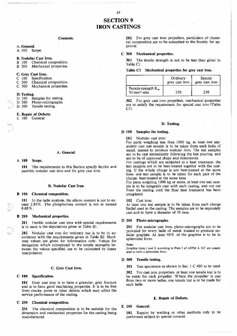
,..-'-.
·,.-,
'·
49
SECTION 9 IRON CASTINGS
Contents.
A. General. A 100 Scope.
B. Nodular Cast Iron. B I 00 Chemical composition. B 200 Mechanical properties.
C. Grey Cast Iron. C I 00 Specification. C 200 Chemical composition. C 300 Mechanical properties.
D. Testing. D I 00 Samples for testing. D 200 Photo-micrographs. D 300 Tensile testing.
E. Repair of Defects.
202 For grey cast iron propellers, particulars of chemical composition are to be submitted to the Society for approval.
C 300 Mechanical properties.
301 The tensile strength is not to be less than given in Table Cl.
Table Cl Mechanical properties for grey cast iron.
Ordinary Special grey cast iron grey cast iron
Tensile strength Rm N/mm2 min. 150 250
302 For grey cast iron propellers, mechanical properties are to satisfy the requirement for special cast iron (Table CI).
E I 00 General. D. Testing.
A. General.
A 100 Scope.
101 The requirements in this Section specify ferritic and pearlitic nodular cast iron and for grey cast iron.
B. Nodular Cast Iron.
B 100 Chemical composition.
101 In the ladle analysis, the silicon content is not to exceed 2,80 % . The phosphorous content is not to exceed 0,08%.
B 200 Mechanical properties.
201 Ferritic nodular cast iron with special requirements is to meet is the stipulations given in Table Bl.
202 Nodular cast iron for ordinary use is to be in accordance with the requirements given in Table B2. Hardness values are given for information only. Values for elongation which correspond to the tensile strengths between the values specified, are to be calculated by linear interpolation.
C. Grey Cast Iron.
C 100 Specification.
101 Grey cast iron is to have a granular, grey fracture and is to have good machining properties. It is to be free from cracks. pores or other defects which may affect the service performance of the casting.
C 200 Chemical composition.
201 The chemical composition is to be suitable for the qimension and mechanical properties for the casting being manufactured.
D 100 Samples for testing.
101 Nodular cast iron' For parts weighing less than I 000 kg, at least one separately cast test sample is to be taken from each ladle of metal, treated to produce nodular iron. The test samples are to be cast immediately following the last pouring, and are to be of approved shape and dimensions. For castings which are subjected to a heat treatment. the test samples are to be heat-treated together with the casting. If the whole charge is not heat-treated at the same time, one test sample is to be taken for each part of the charge, heat-treated at the same time. For parts weighing I 000 kg or more. at least one test sample is to be integrally cast with each casting, and not cut from the casting until the final heat treatment has been completed.
102 Cast iron' At least one test sample is to be taken from each charge (ladle) used in the casting. The samples are to be separately cast and to have a diameter of 30 mm.
D 200 Photo-micrographs.
201 For nodular cast iron, photo-micrographs are to be provided for every ladle of metal, treated to produce nodular graphite. At least 90 % of the graphite is to be in spheroidal form.
Note: Graphite types I and II according to Plate I of ASTM A 24 7 are considered to have a spheroidal form.
D 300 Tensile testing.
301 Test specimens as shown in Sec. I C 400 to be used.
302 For cast iron propellers, at least one tensile test is to be made for each propeller. Where the propeller is cast from two or more ladles, one tensile test is to be made for each ladle.
E. Repair of Defects.
E 100 General.
101 Repairs by welding or other methods only to be performed subject to special consent.

50
Table Bl Ferritic nodular cast iron with special requirements.
Impact energy,
Grade Tensile strength Yield strength
Rm NI mm'. min. ReH resp. Rpo.z Elongation KV at ambient
NI mm'. min. As %,min. temp.
Average of 3 tests, Jmin.
NV l D 2l 340 215 22 20 NV2 2) 390 245 l 8 16
I) If used at temperatures below .0°C. impact testing is to be carried out at service temperatures. 2) Subject to agreement with the society the impact teSt at ambient temperature may be omitted, provided that the castings are subjected
to a satisfactory heat treatment, and that the manufacturer submits comprehensive test data from the running production. verifying that the requirements specified are consistently met.
Table B2 Nodular cast iron for ordinary use.
Tensile strength Yield strength Elongation HB Structure Rm NI mm'. min. ReH resp. Rpo.2 As %,min. Typical ranges
N/mm'. min.
Ferrite 390 245 12 150-200 Ferrite/Pearlite 490 - 7 l 70-240 Pearlite 590 - 3 210-280 Pear lite 690 - 2 230-300