Embed Size (px)
Citation preview
0
Mobile Platform with Leg-Wheel Mechanismfor Practical Use
Shuro NakajimaThe Department of Advanced Robotics, Chiba Institute of Technology
Japan
1. Introduction
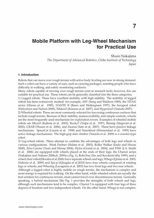
Robots that can move over rough terrain with active body leveling are now in strong demand.Such a robot can have a variety of uses, such as carrying packages, assisting people who havedifficulty in walking, and safety monitoring outdoors.Many robots capable of moving over rough terrain exist as research tools; however, few aresuitable for practical use. These robots can be generally classified into the three categories.1) Legged robots: These have excellent mobility with high stability. The mobility of leggedrobots has been extensively studied: for example, ASV (Song and Waldron 1989), the TITANseries (Hirose et al. 1985), DANTE II (Bares and Wettergreen 1997), the hexapod robot(Delcomyn and Nelson 2000), Tekken2 (Kimura et al. 2007), and Hyperion3 (Yoneda 2007).2) Wheeled robots: These are most commonly selected for traversing continuous surfaces thatinclude rough terrain. Because of their stability, maneuverability, and simple controls, wheelsare the most frequently used mechanism for exploration rovers. Examples of wheeled mobilerobots are Micro5 (Kubota et al. 2003), Rocky7 (Volpe et al. 1997), Shrimp (Siegwart et al.2002), CRAB (Thueer et al. 2006), and Zaurus (Sato et al. 2007). These have passive linkagemechanisms. SpaceCat (Lauria et al. 1998) and Nanokhod (Winnendael et al. 1999) haveactive linkage mechanisms. The high-grip stair climber (Yoneda et al. 2009) is a crawler-typerobot.3) Leg-wheel robots: These attempt to combine the advantages of both legs and wheels invarious configurations. Work Partner (Halme et al. 2003), Roller Walker (Endo and Hirose2000), Zero Carrier (Yuan and Hirose 2004), Hylos (Grand et al. 2004), and PAW (J.A. Smithet al. 2006) are equipped with wheels placed at the ends of their legs; the Chariot series(Nakajima and Nakano 2008a,b, 2009a-c,Fig. 1), RoboTrac (Six and Kecskem’ethy 1999), and awheel chair robot(Morales et al.2006) have separate wheels and legs; Whegs (Quinn et al. 2003;Daltorio et al. 2009) and Epi.q-1(Quaglia et al.2010) have four wheels composed of rotatinglegs or wheels; and Wheeleg (Lacagnina et al. 2003) has two front legs and two rear wheels.Although a legged robot is highly mobile on rough terrain, the mechanism is complex andmore energy is required for walking. On the other hand, while wheeled robots are usually thebest solution for continuous terrain, most cannot travel over discontinuous terrain. Generallyspeaking, a hybrid mechanism like Fig. 1 provides the strengths of both wheels and legs,although such mechanisms tend to be complex. Chariot 3 is equipped with four legs of threedegrees of freedom and two independent wheels. On the other hand, Whegs is not complex,
7
www.intechopen.com
2 Mobile Robot / Book 3
(a) (b)
Fig. 1. A leg-wheel robot. (a)Chariot 3. (b)Chari-Bee is a demonstration robot of Aichi EXPO,2005.
but the posture of its body cannot be easily controlled. PAW has both wheel and leg modeswith a simple mechanism and can control its posture in wheel mode by adjusting each legtip position; however, PAW cannot get over a step statically while maintaining a horizontalposture. The evaluation point for the mechanism in this chapter is to maintain the horizontalposture of the body on rough terrain statically, because a person or object should be carriedstably on the robot.
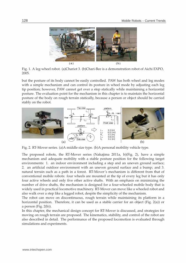
LA 0.3 [m]LW 0.21 [m]Rw 0.1 [m]LB 0.6 [m]hg 0.1 [m]
rf , ( rr : rear)z
x
Front view
LW
platform
x
y sfsr
LA
LB
p
wheel
zy
Top view
Sideview
Front
Rw
platform
hg
Rear+
-
+
-
+ -
+ -
(a) (b)
Fig. 2. RT-Mover series. (a)A middle size type. (b)A personal mobility vehicle type.
The proposed robots, the RT-Mover series (Nakajima 2011a, b)(Fig. 2), have a simplemechanism and adequate mobility with a stable posture position for the following targetenvironments: 1. an indoor environment including a step and an uneven ground surface;2. an artificial outdoor environment with an uneven ground surface and a bump; and 3.natural terrain such as a path in a forest. RT-Mover’s mechanism is different from that ofconventional mobile robots: four wheels are mounted at the tip of every leg but it has onlyfour active wheels and only five other active shafts. With an emphasis on minimizing thenumber of drive shafts, the mechanism is designed for a four-wheeled mobile body that iswidely used in practical locomotive machinery. RT-Mover can move like a wheeled robot andalso walk over a step like a legged robot, despite the simplicity of the mechanism.The robot can move on discontinuous, rough terrain while maintaining its platform in ahorizontal position. Therefore, it can be used as a stable carrier for an object (Fig. 2(a)) ora person (Fig. 2(b)).In this chapter, the mechanical design concept for RT-Mover is discussed, and strategies formoving on rough terrain are proposed. The kinematics, stability, and control of the robot arealso described in detail. The performance of the proposed locomotion is evaluated throughsimulations and experiments.
128 Mobile Robots – Current Trends
www.intechopen.com
Mobile Platform with Leg-Wheel Mechanism
for Practical Use 3
2. RT-mover
2.1 Mechanical concept
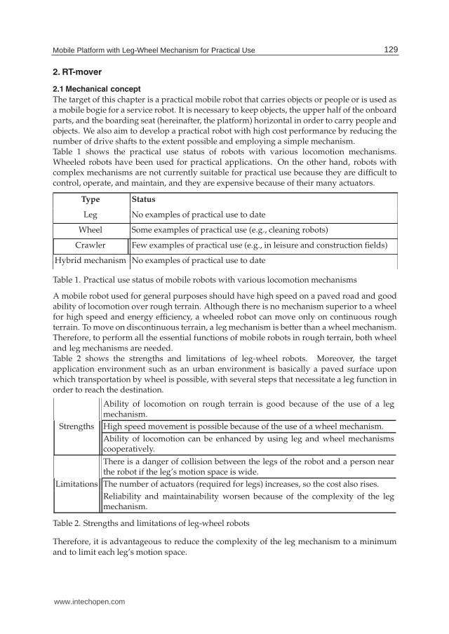
The target of this chapter is a practical mobile robot that carries objects or people or is used asa mobile bogie for a service robot. It is necessary to keep objects, the upper half of the onboardparts, and the boarding seat (hereinafter, the platform) horizontal in order to carry people andobjects. We also aim to develop a practical robot with high cost performance by reducing thenumber of drive shafts to the extent possible and employing a simple mechanism.Table 1 shows the practical use status of robots with various locomotion mechanisms.Wheeled robots have been used for practical applications. On the other hand, robots withcomplex mechanisms are not currently suitable for practical use because they are difficult tocontrol, operate, and maintain, and they are expensive because of their many actuators.
Type Status
Leg No examples of practical use to date
Wheel Some examples of practical use (e.g., cleaning robots)
Crawler Few examples of practical use (e.g., in leisure and construction fields)
Hybrid mechanism No examples of practical use to date
Table 1. Practical use status of mobile robots with various locomotion mechanisms
A mobile robot used for general purposes should have high speed on a paved road and goodability of locomotion over rough terrain. Although there is no mechanism superior to a wheelfor high speed and energy efficiency, a wheeled robot can move only on continuous roughterrain. To move on discontinuous terrain, a leg mechanism is better than a wheel mechanism.Therefore, to perform all the essential functions of mobile robots in rough terrain, both wheeland leg mechanisms are needed.Table 2 shows the strengths and limitations of leg-wheel robots. Moreover, the targetapplication environment such as an urban environment is basically a paved surface uponwhich transportation by wheel is possible, with several steps that necessitate a leg function inorder to reach the destination.
Ability of locomotion on rough terrain is good because of the use of a legmechanism.
Strengths High speed movement is possible because of the use of a wheel mechanism.
Ability of locomotion can be enhanced by using leg and wheel mechanismscooperatively.
There is a danger of collision between the legs of the robot and a person nearthe robot if the leg’s motion space is wide.
Limitations The number of actuators (required for legs) increases, so the cost also rises.
Reliability and maintainability worsen because of the complexity of the legmechanism.
Table 2. Strengths and limitations of leg-wheel robots
Therefore, it is advantageous to reduce the complexity of the leg mechanism to a minimumand to limit each leg’s motion space.
129Mobile Platform with Leg-Wheel Mechanism for Practical Use
www.intechopen.com
4 Mobile Robot / Book 3
We take a four-wheeled mobile body often used in practice as the starting point in consideringthe mechanism of the proposed robot, and from there we develop the proposed mechanism.When seeking a high degree of ability of locomotion on rough terrain in a highly used wheelmode, it is clear that each of the four wheels should generate good driving force. In addition,when driving on rough terrain, each of the wheels of a four-wheeled mobile body is requiredto be driven independently, since each wheel travels a different route. Accordingly, thisdiscussion is based on a four-wheeled mobile body that drives each wheel independently.
2.2 Mechanical design
Cost, reliability, and maintainability are important for practical mobile bodies. These factorscan be evaluated from the number of drive shafts to a certain extent. In other words, usingfewer drive shafts tends to lower the cost and simplify the mechanism, which in turn leadsto increased reliability and maintainability. The above is evident if a comparison is madebetween practical transport machinery, such as automobiles and trains, and the mobile robotcurrently being developed.Since the objective for the robot developed in this chapter is to add the minimum leg functionsnecessary, a mechanism that minimizes the number of added drive shafts is designed.Specifically, after listing possible mechanisms for each function, the mechanism with theminimum number of drive shafts is chosen for the proposed robot with consideration of thepossible combinations.
2.2.1 Steering function
Practical mechanisms to achieve a steering function for a four-wheeled mobile body are shownin Fig. 3(a). Needless to say, there are other mechanisms to achieve steering, but we aim torealize a practical mobile robot. Accordingly, the following discussion targets highly practicalrepresentative mechanisms. The mechanism of 1-1 is the Ackermann steering system, anautomobile steering system. That of 1-3 is a mechanism that rotates the center of a shaft tosteer. It is possible to attach a steering mechanism to the rear wheels of both 1-1 and 1-3.However, this case is the same as 1-1 and 1-3 and is omitted from following discussion. Thoseof 1-2 and 1-4 are 4-Wheel Steering (4WS) systems in which the four wheels can be directed.
2.2.2 Suspension function in wheel mode
The wheels are required to have active vertical travel according to terrain in order to keepthe platform horizontal when moving on gently varying irregular terrain. Systems to fulfillthis requirement are shown in Fig. 3(b). The mechanism of 2-1 provides an up-down functionto each wheel. The necessary number of drive shafts is four, and the platform can be kepthorizontal on rough terrain by the vertical movement of each wheel according to the groundsurface.The mechanism of 2-2 is a bogie mechanism for the left and right wheel that uses a rotatingshaft as a drive shaft. The horizontal degree of the roll direction of the platform can bemaintained by the active control of the rotating shaft of front and rear bogie mechanism inresponse to the ground surface. The horizontal degree of the pitch direction of the platform ismaintained by attaching an independent pitch control shaft. The number of necessary driveshafts is three.The mechanism of 2-3 is a bogie mechanism for the front and back wheels.
130 Mobile Robots – Current Trends
www.intechopen.com
Mobile Platform with Leg-Wheel Mechanism
for Practical Use 5
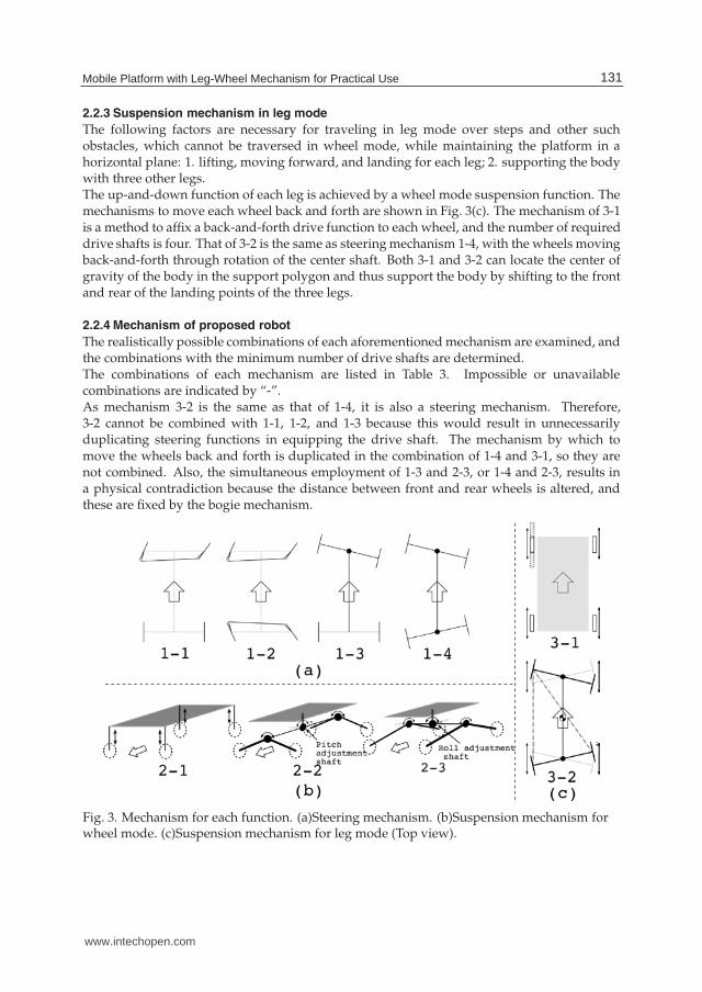
2.2.3 Suspension mechanism in leg mode
The following factors are necessary for traveling in leg mode over steps and other suchobstacles, which cannot be traversed in wheel mode, while maintaining the platform in ahorizontal plane: 1. lifting, moving forward, and landing for each leg; 2. supporting the bodywith three other legs.The up-and-down function of each leg is achieved by a wheel mode suspension function. Themechanisms to move each wheel back and forth are shown in Fig. 3(c). The mechanism of 3-1is a method to affix a back-and-forth drive function to each wheel, and the number of requireddrive shafts is four. That of 3-2 is the same as steering mechanism 1-4, with the wheels movingback-and-forth through rotation of the center shaft. Both 3-1 and 3-2 can locate the center ofgravity of the body in the support polygon and thus support the body by shifting to the frontand rear of the landing points of the three legs.
2.2.4 Mechanism of proposed robot
The realistically possible combinations of each aforementioned mechanism are examined, andthe combinations with the minimum number of drive shafts are determined.The combinations of each mechanism are listed in Table 3. Impossible or unavailablecombinations are indicated by “-”.As mechanism 3-2 is the same as that of 1-4, it is also a steering mechanism. Therefore,3-2 cannot be combined with 1-1, 1-2, and 1-3 because this would result in unnecessarilyduplicating steering functions in equipping the drive shaft. The mechanism by which tomove the wheels back and forth is duplicated in the combination of 1-4 and 3-1, so they arenot combined. Also, the simultaneous employment of 1-3 and 2-3, or 1-4 and 2-3, results ina physical contradiction because the distance between front and rear wheels is altered, andthese are fixed by the bogie mechanism.
Fig. 3. Mechanism for each function. (a)Steering mechanism. (b)Suspension mechanism forwheel mode. (c)Suspension mechanism for leg mode (Top view).
131Mobile Platform with Leg-Wheel Mechanism for Practical Use
www.intechopen.com
6 Mobile Robot / Book 3
Steering Suspension Suspension Number of(wheel mode) (leg mode) drive shafts
1-1 2-1 3-1 / 3-2 9 / -2-2 3-1 / 3-2 8 / -2-3 3-1 / 3-2 8 / -
1-2 2-1 3-1 / 3-2 10/ -2-2 3-1 / 3-2 9 / -2-3 3-1 / 3-2 9 / -
1-3 2-1 3-1 / 3-2 7 / -2-2 3-1 / 3-2 6 / -2-3 3-1 / 3-2 - / -
1-4 2-1 3-1 / 3-2 - / 62-2 3-1 / 3-2 - / 52-3 3-1 / 3-2 - / -
Table 3. Combinations of each mechanism
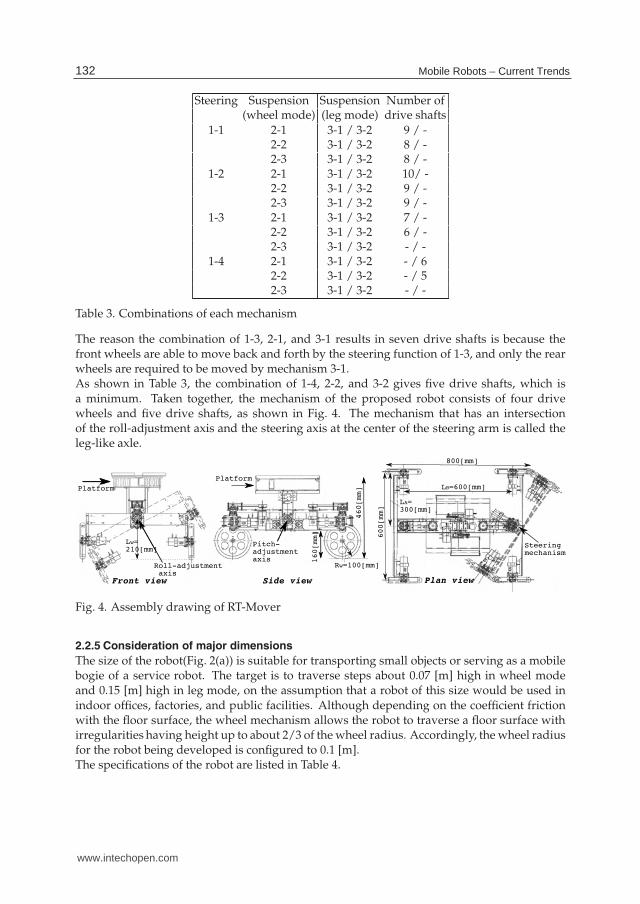
The reason the combination of 1-3, 2-1, and 3-1 results in seven drive shafts is because thefront wheels are able to move back and forth by the steering function of 1-3, and only the rearwheels are required to be moved by mechanism 3-1.As shown in Table 3, the combination of 1-4, 2-2, and 3-2 gives five drive shafts, which isa minimum. Taken together, the mechanism of the proposed robot consists of four drivewheels and five drive shafts, as shown in Fig. 4. The mechanism that has an intersectionof the roll-adjustment axis and the steering axis at the center of the steering arm is called theleg-like axle.
800[mm]
600[mm]
Steeringmechanism
Pitch-adjustment axis
Platform
Front view Plan viewSide view
Platform
Roll-adjustment axis
Lw=210[mm]
LB=600[mm]
LA=300[mm]
Rw=100[mm]
460[mm]
160[mm]
Pitch-adjustmentaxis
Fig. 4. Assembly drawing of RT-Mover
2.2.5 Consideration of major dimensions
The size of the robot(Fig. 2(a)) is suitable for transporting small objects or serving as a mobilebogie of a service robot. The target is to traverse steps about 0.07 [m] high in wheel modeand 0.15 [m] high in leg mode, on the assumption that a robot of this size would be used inindoor offices, factories, and public facilities. Although depending on the coefficient frictionwith the floor surface, the wheel mechanism allows the robot to traverse a floor surface withirregularities having height up to about 2/3 of the wheel radius. Accordingly, the wheel radiusfor the robot being developed is configured to 0.1 [m].The specifications of the robot are listed in Table 4.
132 Mobile Robots – Current Trends
www.intechopen.com
Mobile Platform with Leg-Wheel Mechanism
for Practical Use 7
Dimensions Length 0.8[m]; Width 0.63[m] (Tread 0.6[m]); Height 0.46[m];Height to bottom 0.16[m]
Wheel Radius:0.1[m]; Width:0.03[m]Weight 28[kg] (including the platform at 6.5[kg] and batteries at 5.4[kg])
Motor 23[W] (front and rear steering θs f , θsr: ×2)
(DC servo) 40[W] (front and rear roll θr f , θrr: ×2; pitch θp: ×2(double motor);each wheel: ×4)
100 (steering θs f , θsr, and roll θr f , θrr)
Gear ratio 250 (pitch θp)50 (each wheel)Encoder (each motor)
Sensor Current sensor (each motor)Posture angle sensor (roll and pitch of platform)
Angle limit ±30 (steering θs f , θsr, roll θr f , θrr, and pitch θp)
Minimum rotation radius 0.52[m]
Max speed 0.63[m/s]
Power supply 24[V] lead accumulator
Table 4. Main specifications
The length of the steering arm (tread) was 0.6 [m], and the maximum angle for steering,roll-adjustment axis, and pitch-adjustment axis was ±30 [deg]. When rotating theroll-adjustment axis through 30[deg] such that the wheel on one side is in contact with theground, the other wheel attached to a 0.6[m] steering arm can rise 0.3[m]. Therefore, themovement range is sufficient for this initial step. Likewise, moving 0.3[m] in the front and reardirections is possible by moving the steering from 0[deg] to 30[deg], and holes of 0.3[m] canbe crossed (Fig. 7(c)). Also, the radius of rotation is 0.52[m] if the front and rear steering anglesare turned a full 30[deg] in antiphase. With regards to locomotion on a slope, back-and-forthmovement and traversal of a slope of up to 30[deg] is possible.
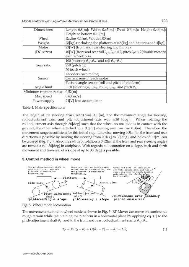
3. Control method in wheel mode
The pitch-adjustment shaft iswell controlled, and theplatform is maintainedhorizontally.
Front and rear roll-adjustmentshafts are well controlled, andthe platform is maintainedhorizontally.
Side view
Pitch-adjustment shaft
(a)Ascending a slope (b)Crossing a slope(c)Movement over randomly placed obstacles
Front and rear leg-like axlesare well controlled, and therobot can move on rough terrainmaintaining the platformhorizontally.
Front view
Roll-adjustment shaft
Platform
Fig. 5. Wheel mode locomotion
The movement method in wheel mode is shown in Fig. 5. RT-Mover can move on continuousrough terrain while maintaining the platform in a horizontal plane by applying eq. (1) to thepitch-adjustment shaft θp, and to the front and rear roll-adjustment shafts θr f , θrr.
Td = K(θd − θ) + D(θ̇d − θ̇) = −Kθ − Dθ̇, (1)
133Mobile Platform with Leg-Wheel Mechanism for Practical Use
www.intechopen.com

8 Mobile Robot / Book 3
where Td is the target torque, θ is the posture angle of the platform, θd: target posture angle ofthe platform (= 0), K is the angle gain, and D is the angular velocity gain.
3.1 Assessment of ability of locomotion in wheel mode
The situations of (a) and (b) shown in Fig. 5 partially appear in (c). Therefore, Fig. 5(c) aloneis evaluated by simulation. The conditions employed in the simulation are as follows. Eachgain value is obtained experimentally. For the initial step of the study, the velocity is set suchthat movement in the static state is possible. Since high speeds are a characteristic of wheeldriving systems, traveling states with dynamic behavior will be studied in the near future.
1. Kp =800[N·m], Dp =15[N·m·s], Kr f = Krr =250[N·m], Dr f = Drr =10[N·m·s].
2. The speeds of all the wheels are maintained at a constant 0.2[m/s].
3. The front and rear steering angles are maintained at 0.
4. The wheels and steering are controlled using a proportional derivative (PD) controller.
5. The coefficient of friction between wheel and road is 0.7, and there is no friction on theshafts of the robot.
6. Open Dynamics Engine (ODE) is used for simulation.
Figure 6 shows a simulation of moving from point A to B in Fig. 6(a) over randomly placedobstacles. In (b) and (c) we see that each adjustment shaft is controlled appropriately, as wellas that the platform’s posture angle remains horizontal to within ±0.8[deg]. This shows thatin wheel mode the platform can move over rough terrain with obstacles about 2/3 the size ofthe wheel radius as shown in the figure.When a wheel hits an obstacle, the steering shaft is turned because of the reaction force fromthe obstacle. If the robot is required to move exactly straight, it is necessary to adjust thecorresponding wheel speed according to both the rotation angle of the steering shaft and thatof the roll-adjustment shaft. This is a subject for future study.
4. Gait strategy and control method in leg mode
The leg mode locomotion method is shown in Fig. 7. As an initial step, evaluations areperformed by simulations and experiments taking Fig. 7 (a) and (b) as examples.In the future, a method for integrating external sensor information with the robot system willbe studied because, for example, such information is necessary to recognize a downward stepbefore descending in Fig. 7(b). At the current stage, road shapes are known in advance.
4.1 Step-up gait
Using the control method in eq. (1), RT-Mover can move over rough terrain where its wheelscan be in continuous contact with the ground. However, with steps higher than the wheelradius or gaps larger than the wheel diameter, the ground contact points of wheels need to bealtered by lifting the wheels. The case of lifting a wheel onto a step which the robot cannotclimb in wheel mode is shown in Fig. 8. Assuming that static stability is maintained, a wheelis lifted like a leg while the body is constantly supported on at least three wheels.Figure 9 shows the flow of the step-up gait. Before and after an upward step, the robot runs inwheel mode (Fig. 9(a) and (l)). When a front wheel reaches the step, the rear steering is rotatedso that the margin of static stability during leg motion increases (Fig. 9(b)). Since RT-Movercannot adjust the position of its center of gravity due to having a small number of degrees of
134 Mobile Robots – Current Trends
www.intechopen.com

Mobile Platform with Leg-Wheel Mechanism
for Practical Use 9
-8
-6
-4
-2
0
2
4
6
8
0 1 2 3 4 5 6 7 8 9
angle
[deg]
time[s]
Pitch angle of the platform
Angle of pitch-adjustment shaft
(b)
-8
-6
-4
-2
0
2
4
6
8
0 1 2 3 4 5 6 7 8 9
angle
[deg]
time[s]
Roll angle of the platform
Front roll-adjustment shaft’s angle
Rear roll-adjustment shaft’s angle
(c)
Fig. 6. Simulation of moving over randomly placed obstacles. (a) Shape of the road and ascene from the simulation. (b) Platform’s pitch and the angle of the pitch-adjustment shaft.(c) Data on platform’s roll and the angles of the front and rear roll-adjustment shafts for themovement from point A to B in (a).
Upward step
Plan view
The robot raises eachfront wheel using thefront leg-like axle.
sideview
frontview
Leg-like axles andthe pitch-adjustmentshaft are wellcontrolled, and theplatform is maintainedhorizontally whenascending a step.
Upwardstep
(a)Ascending a step
Step
(b)Descending a step
The robot lowers eachfront wheel using thefront leg-like axle.
The robot lowers eachback wheel using therear leg-like axlein the same way. (c)Stepping over
a hole or an obstacle
Each front wheel steps overa hole. After that, each rearwheel steps over it in thesame way.
Fig. 7. Leg mode locomotion
(a)The front-left wheel is lifted. (b)The front-left wheel is swung. (c)The front-left wheel is landed.
Upward
step
Front-left
wheel
Front-right
wheel
Posture control
Posture control(pitch-adjustment shaft)
Angle control
(front roll-
adjustment
shaft)
Posture control
(rear roll-adjustment
shaft)
Angle control
Posture control
Angle control
Fig. 8. Leg motion of front-left wheel
135Mobile Platform with Leg-Wheel Mechanism for Practical Use
www.intechopen.com
10 Mobile Robot / Book 3
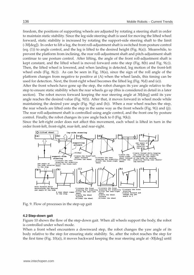
freedom, the positions of supporting wheels are adjusted by rotating a steering shaft in orderto maintain static stability. Since the leg-side steering shaft is used for moving the lifted wheelforward, static stability is increased by rotating the support-side steering shaft to the limit(-30[deg]). In order to lift a leg, the front roll-adjustment shaft is switched from posture control(eq. (1)) to angle control, and the leg is lifted to the desired height (Fig. 8(a)). Meanwhile, toprevent the platform from inclining, the rear roll-adjustment shaft and pitch-adjustment shaftcontinue to use posture control. After lifting, the angle of the front roll-adjustment shaft iskept constant, and the lifted wheel is moved forward onto the step (Fig. 8(b) and Fig. 9(c)).Then, the lifted wheel is lowered, and when landing is detected, leg motion of the front-leftwheel ends (Fig. 8(c)). As can be seen in Fig. 18(a), since the sign of the roll angle of theplatform changes from negative to positive at (A) when the wheel lands, this timing can beused for detection. Next, the front-right wheel becomes the lifted leg (Fig. 9(d) and (e)).After the front wheels have gone up the step, the robot changes its yaw angle relative to thestep to ensure static stability when the rear wheels go up (this is considered in detail in a latersection). The robot moves forward keeping the rear steering angle at 30[deg] until its yawangle reaches the desired value (Fig. 9(f)). After that, it moves forward in wheel mode whilemaintaining the desired yaw angle (Fig. 9(g) and (h)). When a rear wheel reaches the step,the rear wheels are lifted onto the step in the same way as the front wheels (Fig. 9(i) and (j)).The rear roll-adjustment shaft is controlled using angle control, and the front one by posturecontrol. Finally, the robot changes its yaw angle back to 0 (Fig. 9(k)).Since the left-right order does not affect this movement, each wheel is lifted in turn in theorder front-left, front-right, rear-left, and rear-right.
(a) (b) (c) (d) (e) (f)
(g) (h) (i) (j) (k)
(1)rotate the rear steering for stability(2)lift the front-left wheel
(1)move the front-left wheel forward(2)lower the wheel
(1)rotate the rear steering for stability(2)lift the front-right wheel
(1)move the front-right wheel forward(2)lower the wheel
(1)move forwad while keeping the rotated rear steering(2)change the yaw angle of the body for growing stability during rear wheels’ leg motions
move forward whilemaintaining the desiredyaw angle of the body
A rear wheel comesto the step.
(1)rotate the front steering for stability(2)lift the rear-left wheel(3)move the wheel forward(4)lower the wheel
(1)rotate the front steering for stability(2)lift the rear-right wheel(3)move the wheel forward(4)lower the wheel
(l)
:lifted wheel leg-side steering
support-side
steering
yaw angle of the body relative to the step
yaw angle ofthe body relativeto the step
(1)rotate the front steering(2)move forward and change the yaw angle to 0
supporting
polygon
-30[deg]
Fig. 9. Flow of processes in the step-up gait
4.2 Step-down gait
Figure 10 shows the flow of the step-down gait. When all wheels support the body, the robotis controlled under wheel mode.When a front wheel encounters a downward step, the robot changes the yaw angle of itsbody relative to the step for ensuring static stability. So, after the robot reaches the step forthe first time (Fig. 10(a)), it moves backward keeping the rear steering angle at -30[deg] until
136 Mobile Robots – Current Trends
www.intechopen.com
Mobile Platform with Leg-Wheel Mechanism
for Practical Use 11
(a) (b) (c)(d) (e)
(f)
(g)
(h)(i)
(j)
(1)move forwad while keeping the rotated front steering(2)changes the yaw angle to 0
(1)rotate the rear steering for stability(2)lift the front-right wheel
(1)rotate the rear steering for stability(2)lift the front-left wheel(3)move the wheel forward(4)lower the wheel
:lifted wheel
leg-side
steering
support-side
steeringyaw angle of the body relative to the step
(1)rotate the rear steering(2)move backward and changes the yaw angle of the body
(k) (l)
move forward to the stepwhile maintaining thedesired yaw angle of thebody
(1)rotate the rear steering(2)move forward and changes the yaw angle to 0
(1)move the wheel forward(2)lower the wheel
move forward to the step
(1)rotate the front steering for stability(2)lift the rear-left wheel(3)move the wheel forward(4)lower the wheel
(1)rotate the front steering for stability(2)lift the rear-right wheel(3)move the wheel forward(4)lower the wheel
reach adownwardstep
movebackward
Fig. 10. Flow of processes in the step-down gait
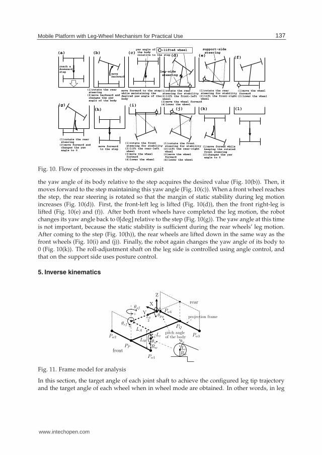
the yaw angle of its body relative to the step acquires the desired value (Fig. 10(b)). Then, itmoves forward to the step maintaining this yaw angle (Fig. 10(c)). When a front wheel reachesthe step, the rear steering is rotated so that the margin of static stability during leg motionincreases (Fig. 10(d)). First, the front-left leg is lifted (Fig. 10(d)), then the front right-leg islifted (Fig. 10(e) and (f)). After both front wheels have completed the leg motion, the robotchanges its yaw angle back to 0[deg] relative to the step (Fig. 10(g)). The yaw angle at this timeis not important, because the static stability is sufficient during the rear wheels’ leg motion.After coming to the step (Fig. 10(h)), the rear wheels are lifted down in the same way as thefront wheels (Fig. 10(i) and (j)). Finally, the robot again changes the yaw angle of its body to0 (Fig. 10(k)). The roll-adjustment shaft on the leg side is controlled using angle control, andthat on the support side uses posture control.
5. Inverse kinematics
Pw1
Pw2
Pw4
Pw3
PP
PQ
X
Z
YθpB
θsf
θrf
LA
LB
2
θw
Rw
LW
front
rear
θw
Rw
pitch angleof the body
+
+
+
projection frame
+
Lr
Lr
Fig. 11. Frame model for analysis
In this section, the target angle of each joint shaft to achieve the configured leg tip trajectoryand the target angle of each wheel when in wheel mode are obtained. In other words, in leg
137Mobile Platform with Leg-Wheel Mechanism for Practical Use
www.intechopen.com

12 Mobile Robot / Book 3
mode, for example, the inverse kinematics to achieve the trajectory by lifting the transfer legvertically, swinging it forward, and setting it down vertically to land is described.A “projection frame” is introduced (Fig. 11), which comprises projecting line segmentsconnecting the wheel supporting points (front arm Pw1Pw2, and rear arm Pw3Pw4) and aline segment connecting the centers of the arms (body PPPQ) to a horizontal plane. Here,the inverse kinematics are discussed using this projection frame. We use a right-handedcoordinate system with the center of the projection frame as the origin. The direction of travelis defined as Y and the vertical axis as Z. Then, the following matrix 0Tw f l
maps to coordinateswith the front-left leg at the origin of the body-centered coordinate system:
0Tw f l=
⎛
⎜
⎜
⎝
1 0 0 00 CθpB
−SθpB0
0 SθpBCθpB
00 0 0 1
⎞
⎟
⎟
⎠
⎛
⎜
⎜
⎝
1 0 0 0
0 1 0 LB2
0 0 1 00 0 0 1
⎞
⎟
⎟
⎠
⎛
⎜
⎜
⎝
Cθs f −Sθs f 0 0Sθs f Cθs f 0 0
0 0 1 00 0 0 1
⎞
⎟
⎟
⎠
⎛
⎜
⎜
⎝
Cθr f 0 Sθr f 00 1 0 0
−Sθr f 0 Cθr f 00 0 0 1
⎞
⎟
⎟
⎠
·
⎛
⎜
⎜
⎝
1 0 0 −LA
0 1 0 00 0 1 00 0 0 1
⎞
⎟
⎟
⎠
⎛
⎜
⎜
⎝
1 0 0 00 1 0 00 0 1 −Lr
0 0 0 1
⎞
⎟
⎟
⎠
⎛
⎜
⎜
⎝
1 0 0 00 Cθw −Sθw 00 Sθw Cθw 00 0 0 1
⎞
⎟
⎟
⎠
⎛
⎜
⎜
⎝
1 0 0 00 1 0 00 0 1 −Rw
0 0 0 1
⎞
⎟
⎟
⎠
(2)
5.1 Lifting and landing phases
When lifting or landing the front-right wheel, an angular velocity value will be determinedfor the front roll-adjustment shaft. In order to avoid contacting a lateral surface of the step, thelifted wheel is moved up and down without moving back or forth. The posture control givenby eq. (1) is applied to the pitch adjustment and rear roll-adjustment shafts, and the rotationof the supporting front-left wheel is stopped. In order to widen the supporting polygon, therear steering shaft is rotated to its steering limit. The control parameters of the front steeringshaft, the rear-left wheel, and the rear-right wheel are determined by the value set for the frontroll-adjustment shaft.The derivation of these three control parameters is described in an absolute coordinate systemwith its origin at the supporting position of the front-left wheel Pw1(t), as shown in Fig. 12(a).In Fig. 12(a), the position of the front-right wheel Pw2(t) and Pw2(t + ∆t), when rotating thefront roll-adjustment shaft for a small amount of time ∆t, are calculated. The angular velocityof the front steering shaft, θ̇s f (t), and the velocities of the rear-left and rear-right wheels,Vw3(t) and Vw4(t), are also derived. Since the wheel is moved up and down without movingin the Y direction, the Y coordinate of PP is constant.The distance between Pw1(t) and PP(t) is A f (t); since this is half the distance between Pw1(t)and Pw2(t), it may be derived from eq. (2). According to eq. (2), A f (t) depends on the frontsteering θs f (t), the front roll axis θr f (t), and the body pitch angle θpB (t). The value of A f aftera small incremental movement of θr f (t) is A f (t+ ∆t). Because an analytic solution is difficult,θs f and θpB are approximated as not varying over time ∆t. Since the Y axis moves in a fixedup and down path, the Y coordinate of Pw2 is fixed and is given below:
(Pw2x(t), Pw2y(t)) = (2A f (t) cos(θleg(t) + θB(t)), 2A f (t) sin(θleg(t) + θB(t))), (3)
(Pw2x(t + ∆t), Pw2y(t + ∆t)) = (√
4A f (t + ∆t)2 − Pw2y(t)2, Pw2y(t)), (4)
θleg(t) and θB(t) are obtained by eqs. (6), (7), and (10), when their initial values are given.The velocity of PP and the small angle ∆θo(t) are given by
138 Mobile Robots – Current Trends
www.intechopen.com
Mobile Platform with Leg-Wheel Mechanism
for Practical Use 13
leg(t) + B (t)
o(t)2A f (t)
2A f (t + t)Pw2(t)Pw2(t + t)
Yo
X o
PP (t)
PP (t + t)
Pw1(t)
V P P (t) =Pw2 (t+ t) Pw2(t)
2 t B (t):projection angle ofthebody yaw angle
leg(t)
lifted wheel(front right wheel)
Front part of theprojection framesupporting wheel(front left wheel)
leg + B
V P P
AfPP
Yo
X oFo
Pw2
lifted wheel
LL
LR
Ar
Vw3 sup
B
V P P
V P P w4
V P P w3PP
PQ
B
Vw4
Vw1
Vw2
Vw3
Vw4
O
OH (xH ,yH )
RH
Af
Ar
lw1
lw2
lw3
lw4
B
Pw2y
Pw4y
V Bleg
leg
sup
X
Y
sup
(b)(a)
(c) (d)
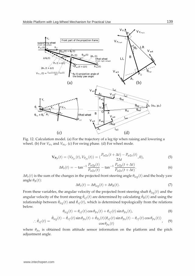
Fig. 12. Calculation model. (a) For the trajectory of a leg tip when raising and lowering awheel. (b) For Vw3 and Vw4 . (c) For swing phase. (d) For wheel mode.
VPP(t) = (VPpx
(t), VPpy(t)) = (
Pw2x(t + ∆t)− Pw2x(t)
2∆t, 0), (5)
∆θo(t) = − tan−1 Pw2y(t)
Pw2x(t)− tan−1 Pw2y(t + ∆t)
Pw2x(t + ∆t). (6)
∆θo(t) is the sum of the changes in the projected front steering angle θleg(t) and the body yawangle θB(t):
∆θo(t) = ∆θleg(t) + ∆θB(t). (7)
From these variables, the angular velocity of the projected front steering shaft θ̇leg(t) and the
angular velocity of the front steering θ̇s f (t) are determined by calculating θ̇B(t) and using the
relationship between θ̇leg(t) and θ̇s f (t), which is determined topologically from the relationsbelow.
θleg(t) = θs f (t) cos θpB(t) + θr f (t) sin θpB(t), (8)
∴ θ̇s f (t) =θ̇leg(t)− θ̇r f (t) sin θpB(t) + θ̇PB
(t)(θs f (t) sin θpB(t)− θr f (t) cos θpB(t))
cos θpB (t), (9)
where θpB is obtained from attitude sensor information on the platform and the pitchadjustment angle.
139Mobile Platform with Leg-Wheel Mechanism for Practical Use
www.intechopen.com
14 Mobile Robot / Book 3
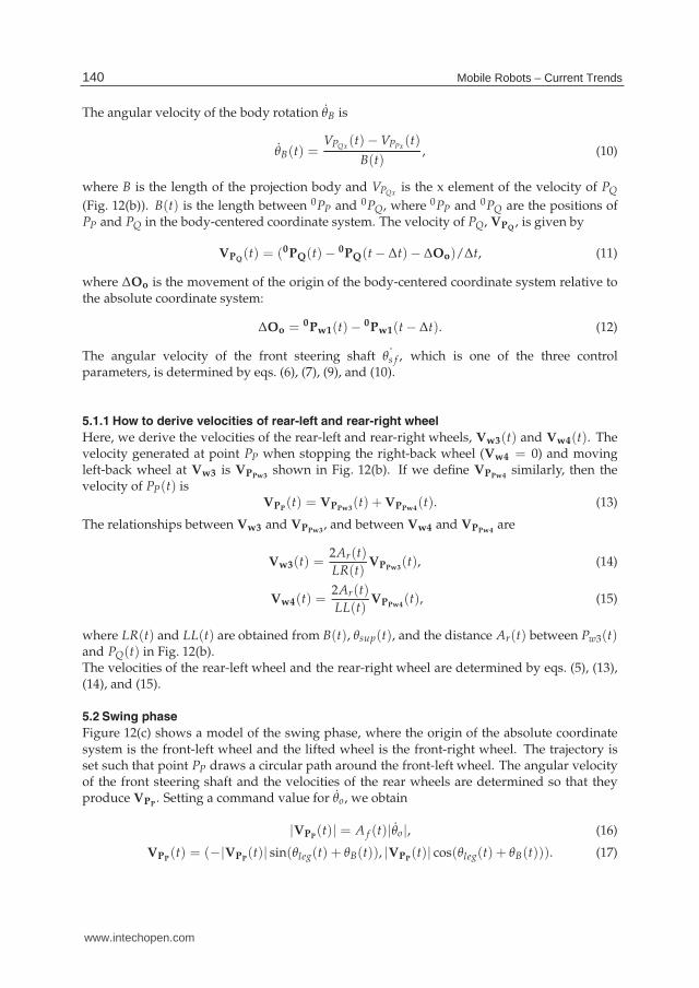
The angular velocity of the body rotation θ̇B is
θ̇B(t) =VPQx
(t)− VPPx(t)
B(t), (10)
where B is the length of the projection body and VPQxis the x element of the velocity of PQ
(Fig. 12(b)). B(t) is the length between 0PP and 0PQ, where 0PP and 0PQ are the positions ofPP and PQ in the body-centered coordinate system. The velocity of PQ, VPQ
, is given by
VPQ(t) = (0PQ(t)− 0PQ(t − ∆t)− ∆Oo)/∆t, (11)
where ∆Oo is the movement of the origin of the body-centered coordinate system relative tothe absolute coordinate system:
∆Oo = 0Pw1(t)−0Pw1(t − ∆t). (12)
The angular velocity of the front steering shaft ˙θs f , which is one of the three controlparameters, is determined by eqs. (6), (7), (9), and (10).
5.1.1 How to derive velocities of rear-left and rear-right wheel
Here, we derive the velocities of the rear-left and rear-right wheels, Vw3(t) and Vw4(t). Thevelocity generated at point PP when stopping the right-back wheel (Vw4 = 0) and movingleft-back wheel at Vw3 is VPPw3
shown in Fig. 12(b). If we define VPPw4similarly, then the
velocity of PP(t) isVPP
(t) = VPPw3(t) + VPPw4
(t). (13)
The relationships between Vw3 and VPPw3, and between Vw4 and VPPw4
are
Vw3(t) =2Ar(t)
LR(t)VPPw3
(t), (14)
Vw4(t) =2Ar(t)
LL(t)VPPw4
(t), (15)
where LR(t) and LL(t) are obtained from B(t), θsup(t), and the distance Ar(t) between Pw3(t)and PQ(t) in Fig. 12(b).The velocities of the rear-left wheel and the rear-right wheel are determined by eqs. (5), (13),(14), and (15).
5.2 Swing phase
Figure 12(c) shows a model of the swing phase, where the origin of the absolute coordinatesystem is the front-left wheel and the lifted wheel is the front-right wheel. The trajectory isset such that point PP draws a circular path around the front-left wheel. The angular velocityof the front steering shaft and the velocities of the rear wheels are determined so that theyproduce VPP
. Setting a command value for θ̇o, we obtain
|VPP(t)| = A f (t)|θ̇o|, (16)
VPP(t) = (−|VPP
(t)| sin(θleg(t) + θB(t)), |VPP(t)| cos(θleg(t) + θB(t))). (17)
140 Mobile Robots – Current Trends
www.intechopen.com
Mobile Platform with Leg-Wheel Mechanism
for Practical Use 15
With the velocity of point PP determined, as in the lifting and landing phases, the threecontrol parameters, the angular velocity of the front steering shaft and the velocities of therear wheels, can be obtained.
5.3 Wheel mode
In Fig. 9(g) and (h), for example, the robot moves with all four wheels supporting the body.Since the velocity of the body center, VB, and the angles of the front and rear steering axes inthe projection frame, θleg and θsup, are given as parameters, the desired wheel velocities withno slipping, Vw1 ∼ Vw4, are derived. Since each wheel rotates about OH , Vwi is given byVwi(t) = lwi(t)VB(t)/RH(t)(i = 1 ∼ 4) where RH(t) is the turning radius. Except underconditions, such as θleg = θsup, where the front and rear steering angles are equal and theturning radius becomes infinite, the topology in Fig. 12(d) leads to
OH(t) = (xH(t), yH(t)) = (B(t)
tan θsup(t)− tan θleg(t),
B(t)
2
tan θsup(t) + tan θleg(t)
tan θsup(t)− tan θleg(t)) (18)
and RH(t) =√
xH(t)2 + yH(t)2. Variables such as lw1 are obtained in the form lw1(t) =|(xH(t)− Pw1x(t))/ cos θleg(t)|.However, when θleg(t) = θsup(t), we have Vwi = VB(i = 1 ∼ 4).
6. Stability in leg mode
In this section, whether the robot can maintain static stability while moving over a target stepof 0.15[m] is analyzed for the gait strategy given above. Static state locomotion is considered asan initial step. In general, statically stable locomotion can be achieved if the center of gravityis located inside the support polygon. Here, the stability during movement of the proposedrobot in leg mode is specifically investigated. For example, the best range of body yaw angleshown in Fig. 9(g) to climb a step while maintaining stability is derived.Figure 13(a) shows the static stability when lifting the front-left wheel. Static stability ispositive if the center of gravity is in the supporting polygon. Since RT-Mover employs amechanism with a small number of driving shafts, it cannot move its center of gravity withoutaltering the position of the supporting wheels. In addition, the supporting point of thefront-right wheel in Fig. 13(a) cannot move since the lifted wheel is needed to move forward.Thus, the rear steering is used so that the center of gravity stays within the supportingpolygon. As shown in Fig. 13(b), if the body inclines backward when going up a step, thecenter of gravity is displaced backward by hg sin θpB , where θpB is the body pitch angle.Figure 14(A) shows four phases during the step-up gait. Out of the four phases in which awheel is lifted during the step-up gait, only those shown in Fig. 14(A-c) and (A-d) cause staticinstability, because the center of gravity is displaced backward due to the backward inclinationof the body and the stability margin consequently decreases. Here, the front steering is rotatedup to the limit of ±30[deg] in the direction that increases stability. First, the rear-left wheelis lifted (Fig. 14(A-c)), moved forward, and then lowered. Next, the rear-right wheel is lifted,moved forward, and lowered. Therefore, the rear steering angle when the rear-right wheelis lifted depends on the rear steering angle when the rear-left wheel is lifted. It can be seenin Fig. 14(A-c) and (A-d) that the less the lifted rear-left wheel goes forward, the more staticstability the robot has at the beginning of lifting the rear-right wheel. Hence, the rear-left
141Mobile Platform with Leg-Wheel Mechanism for Practical Use
www.intechopen.com

16 Mobile Robot / Book 3
θPB
hg
hg sin θPB
(a) (b)
supporting wheellifted wheel
stability margin= min(d1,d2,d3)
d1
d2
d3
supportingpolygon
front-right wheel
rear-leftwheel
rear-rightwheel
Fig. 13. Stability margin
wheel must be advanced by the minimum distance required for going up the step. Since thelifted wheel can be placed on the step from the state shown in Fig. 14(A-c) by advancing it a
distance equal to its radius, θA is set at tan−1(R′
w/(2Ar)), where R′
w = Rw + 0.02[m](margin).
(B)(A)
Fig. 14. Four phases during the gait. (A)The step-up gait. (B)The step-down gait.
Since the rear-left wheel is already on the step when lifting the rear-right wheel, the body pitchangle is smaller in (A-d) than in (A-c).Figure 15 shows the results of numerical calculations of the margin of static stability (theminimum distance between the center of gravity and the supporting polygon) on a 0.15[m]high step. 0.15[m] is the maximum targeted height for the middle size type of RT-Mover.
-0.06
-0.04
-0.02
0
0.02
0.04
0.06
-5 0 5 10 15 20
stability margin[m]
[deg]
[deg]
stable
area
stability margin at the
beginning of lifting
the rear-left wheel
stability margin at the
beginning of lifting
the rear-right wheel
after the rear-left
wheel’s leg motion
(a)The rear steering angle at the beginning
of lifting the rear-left wheel
(b)The rear steering angle at the beginning
of lifting the rear-right wheel
the most
stable angle
-30 -20 -10 0 10
Fig. 15. Static stability data
142 Mobile Robots – Current Trends
www.intechopen.com
Mobile Platform with Leg-Wheel Mechanism
for Practical Use 17
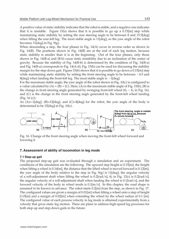
A positive value of static stability indicates that the robot is stable, and a negative one indicatesthat it is unstable. Figure 15(a) shows that it is possible to go up a 0.15[m] step whilemaintaining static stability by setting the rear steering angle to be between 8 and 15.5[deg]when lifting the rear-left leg. The most stable angle is 11[deg], so the yaw angle of the robotbecomes 11[deg] in Fig. 9(g).When descending a step, the four phases in Fig. 14(A) occur in reverse order as shown inFig. 14(B). The positions shown in Fig. 14(B) are at the end of each leg motion, becausestatic stability is smaller than it is at the beginning. Out of the four phases, only thoseshown in Fig. 14(B-a) and (B-b) cause static instability due to an inclination of the center ofgravity. Because the stability of Fig. 14(B-b) is determined by the condition of Fig. 14(B-a)and Fig. 14(B-a) corresponds to Fig. 14(A-d), Fig. 15(b) can be used for discussing the stabilitymargin for the step-down gait. Figure 15(b) shows that it is possible to go down a 0.15[m] stepwhile maintaining static stability by setting the front steering angle to be between −4.5 and8[deg] when landing the front-left leg. The most stable angle is −1[deg].For the maximum stable angle, the yaw angle of the robot shown in Fig. 10(c) is configured toa value calculated by (A) + (B) + (C). Here, (A) is the maximum stable angle of Fig. 15(b), (B) isthe change in front steering angle generated by swinging front-left wheel (θb − θa in Fig. 16),and (C) is the change in the front steering angle generated by the front-left wheel landing(Fig. 16 (c)).As (A)=-1[deg], (B)=12[deg], and (C)=4[deg] for the robot, the yaw angle of the body isdetermined to be 15[deg] in Fig. 10(c).
(a)0.15[m]
side viewtop view
θa
The front steering angle is rotated4[deg] from (b) to (c), because Pp moves forward.
(c)(b)
θb
θb-θa=12[deg]
Pp
Fig. 16. Change of the front steering angle when moving the front-left wheel forward andlowering it
7. Assessment of ability of locomotion in leg mode
7.1 Step-up gait
The proposed step-up gait was evaluated through a simulation and an experiment. Theconditions of the simulation are the following. The upward step height is 0.15[m], the heightwhen lifting a wheel is 0.16[m], the distance that the lifted wheel is moved forward is 0.12[m],the yaw angle of the body relative to the step in Fig. 9(g) is 11[deg], the angular velocityof a roll-adjustment shaft when lifting the wheel is 0.2[rad/s], θ̇0 in Fig. 12(c) is 0.2[rad/s],the angular velocity of a roll-adjustment shaft when landing the wheel is 0.1[rad/s], and theforward velocity of the body in wheel mode is 0.1[m/s]. In this chapter, the road shape isassumed to be known in advance. The robot starts 0.2[m] from the step, as shown in Fig. 17.The configured values are given a margin of 0.01[m] when lifting a wheel onto a step of height0.15[m] and a margin of 0.02[m] when extending the wheel by the wheel radius of 0.1 [m].The configured value of each process velocity in leg mode is obtained experimentally from avelocity that gives static leg motion. There are plans to address high-speed leg processes forboth step-up and step-down gaits in the future.
143Mobile Platform with Leg-Wheel Mechanism for Practical Use
www.intechopen.com
18 Mobile Robot / Book 3
0[s] 2[s] 4[s] 6[s] 8[s] 10[s]
12[s] 14[s] 16[s] 18[s] 20[s] 22[s]
24[s] 26[s] 28[s] 30[s] 34[s] 37.5[s]
0.15[m]0.2[m]
Top view
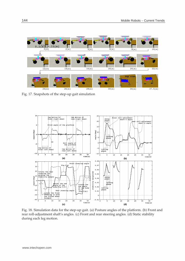
Fig. 17. Snapshots of the step-up gait simulation
-10
-5
0
5
10
0 5 10 15 20 25 30 35
angle[deg]
time[s]
Pitch angle of the platform
Roll angle of
the platform
(a)
(A)
leg motion of
front-left wheel
leg motion of
front-right wheel
leg motion of
rear-left wheel
leg motion of
rear-right wheel
-10
-5
0
5
10
15
20
25
0 5 10 15 20 25 30 35
angle[deg]
time[s]
Front roll-adjustment
shaft’s angle
Rear roll-adjustment
shaft’s angle
(b)
lifting
phase
swing
phase
landing
phase
-40
-30
-20
-10
0
10
20
30
40
0 5 10 15 20 25 30 35
angle[deg]
time[s]
Front steering angle
Rear steering angle
(c)
rotate the rear
steering for
growing the
stability margin
rotate the front
steering to move
the lifted wheel
forward
adjust the yaw
angle of the
body(Fig.9(f))
Fig.9(g)
rotate the
yaw angle
of the body
to 0
(Fig.9(k))
-0.01
0
0.01
0.02
0.03
0.04
0.05
0.06
0.07
0.08
0 5 10 15 20 25 30 35
stability margin[m]
time[s]
(d)
lifting
phase
swing
phase
landing
phase
Fig. 18. Simulation data for the step-up gait. (a) Posture angles of the platform. (b) Front andrear roll-adjustment shaft’s angles. (c) Front and rear steering angles. (d) Static stabilityduring each leg motion.
144 Mobile Robots – Current Trends
www.intechopen.com

Mobile Platform with Leg-Wheel Mechanism
for Practical Use 19
Figure 18 shows the posture of the platform, the angles of the front and rear roll-adjustmentshafts, the front and rear steering angles, and the static stability during each leg motion.Figure 18(a) shows that the pitch posture angle of the platform is almost kept horizontal. Theroll angle of the platform is kept horizontal to within ±3[deg]. At 2.8 ∼ 7.5[s], 9.6 ∼ 14.5[s],20.4 ∼ 25.0[s], and 27.1 ∼ 31.6[s], the roll angle is larger than at other times because thetwisting force around the body, caused by the roll-adjustment shaft that produces the torquefor lifting a wheel, disturbs the posture control of the other roll-adjustment shaft. The timingsgiven are those during each leg motion.Figure 18(b) shows the transition of angles of the front and rear roll-adjustment shafts.From 2.8[s] to 7.5[s], the front-left wheel is lifted. First, the wheel is lifted until the frontroll-adjustment shaft is rotated at 18[deg] (2.8[s] to 4.9[s]). From 4.9[s] to 5.9[s], the frontsteering is rotated until it reaches −14.5[deg] so that the wheel moves forward 0.12[m](Fig. 18(c)). Then the wheel moves downward from 5.9[s] to 7.5[s]. Since the roll angle ofthe platform changes from negative to positive at 7.5[s]((A) in Fig. 18(a)), the landing of thewheel can be detected. The other legs behave similarly.Figure 18(c) shows the transition of angles of the front and rear steering shafts. From 2.8[s]to 7.5[s], the front wheels are lifted. While the front-left wheel is lifted, the rear steering shaftrotates to its steering limit of −30[deg] (1.8[s] to 7.5[s]) so that the static stability increases.After lifting the front-left wheel, the wheel is moved forward until the front steering anglebecomes −14.5[deg] (4.9[s] to 5.9[s]). While the front-right wheel is lifted, the rear steeringshaft is maintained at the steering limit of 30[deg] (9.6[s] to 14.5[s]) so that the static stabilityincreases. The rear steering shaft is also maintained at 30[deg] (14.5[s] to 15.9[s]) after the frontwheels are lifted, thereby adjusting the yaw angle of the body relative to the step to 11[deg] forlifting the rear wheels. Rear wheels are lifted between 20.4[s] and 31.6[s]. While the rear-leftwheel is lifted, the wheel is moved forward 0.12[m] until the rear steering shaft reaches anangle of −10.8[deg] (22.1[s] to 23.1[s]). The front steering shaft is rotated to ± 30[deg] in orderto ensure static stability.Figure 18(d) shows the data for static stability only during leg motion, because static stabilityis large enough during wheel mode. The figure shows that the static stability is maintained.When lifting the front-left wheel, the static stability increases, because the center of gravityof the robot moves backward according to the body pitch (2.8[s] to 4.9[s]). In the swingphase of the front-left wheel, static stability decreases, because the position of the front-rightwheel with respect to the body changes and the supporting polygon becomes smaller (4.9[s]to 5.9[s]). Finally, in its landing phase, static stability decreases, because the center of gravityof the robot moves forward due to the body pitch (5.9[s] to 7.5[s]).Figure 19 shows scenes from a step-up gait experiment and the experimental data. Theconditions of the experiment are the same as those of the simulation except the D gains foreach shaft are set experimentally. The actual robot can also move up onto the 0.15[m]-highstep, and the features of the experimental data are almost the same as those of the simulationdata. However, it takes about 2.5[s] longer to perform the movement in the experiment thanin the simulation. The main reason is that the detection of the landing of each wheel isdelayed due to a difference in the posture of the platform between the simulation and theexperiment. The inclination of the pitch angle of the platform is larger in the experiment thanin the simulation, because of the backlash of the pitch-adjustment shaft and the friction actingon it in the actual robot. Thus, the proposed step-up gait was proved to be effective.
145Mobile Platform with Leg-Wheel Mechanism for Practical Use
www.intechopen.com
20 Mobile Robot / Book 3
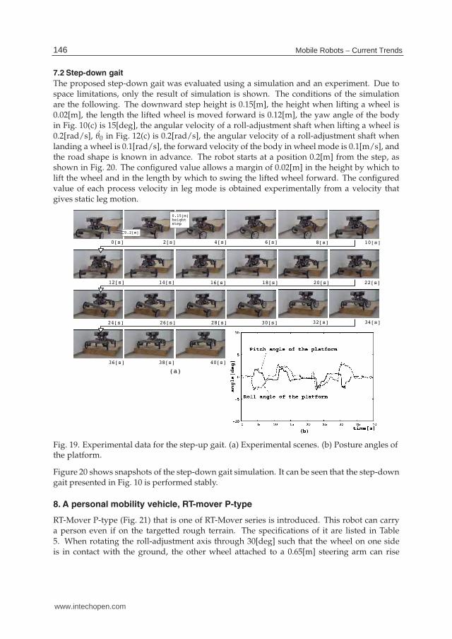
7.2 Step-down gait
The proposed step-down gait was evaluated using a simulation and an experiment. Due tospace limitations, only the result of simulation is shown. The conditions of the simulationare the following. The downward step height is 0.15[m], the height when lifting a wheel is0.02[m], the length the lifted wheel is moved forward is 0.12[m], the yaw angle of the bodyin Fig. 10(c) is 15[deg], the angular velocity of a roll-adjustment shaft when lifting a wheel is0.2[rad/s], θ̇0 in Fig. 12(c) is 0.2[rad/s], the angular velocity of a roll-adjustment shaft whenlanding a wheel is 0.1[rad/s], the forward velocity of the body in wheel mode is 0.1[m/s], andthe road shape is known in advance. The robot starts at a position 0.2[m] from the step, asshown in Fig. 20. The configured value allows a margin of 0.02[m] in the height by which tolift the wheel and in the length by which to swing the lifted wheel forward. The configuredvalue of each process velocity in leg mode is obtained experimentally from a velocity thatgives static leg motion.
0[s] 2[s] 4[s] 6[s] 8[s] 10[s]
12[s] 14[s] 16[s] 18[s] 20[s] 22[s]
24[s] 26[s] 28[s] 30[s] 32[s] 34[s]
36[s] 38[s] 40[s]
0.15[m]heightstep
(a)
0.2[m]
Fig. 19. Experimental data for the step-up gait. (a) Experimental scenes. (b) Posture angles ofthe platform.
Figure 20 shows snapshots of the step-down gait simulation. It can be seen that the step-downgait presented in Fig. 10 is performed stably.
8. A personal mobility vehicle, RT-mover P-type
RT-Mover P-type (Fig. 21) that is one of RT-Mover series is introduced. This robot can carrya person even if on the targetted rough terrain. The specifications of it are listed in Table5. When rotating the roll-adjustment axis through 30[deg] such that the wheel on one sideis in contact with the ground, the other wheel attached to a 0.65[m] steering arm can rise
146 Mobile Robots – Current Trends
www.intechopen.com

Mobile Platform with Leg-Wheel Mechanism
for Practical Use 21
0[s]
2[s] 4[s] 6[s] 8[s] 10[s]
12[s] 14[s] 16[s] 18[s] 20[s] 22[s]
24[s] 26[s] 28[s] 30[s] 32[s] 34[s]
36[s] 38[s] 40[s] 42[s] 44[s] 48[s]
0[s]
step height=0.15[m]
0.2[m]
Fig. 20. Snapshots of the step-down gait simulation
0.325[m]. Therefore, the movement range is sufficient for the targeted terrain. Likewise,moving 0.325[m] in the front and rear directions is possible by moving the steering from0[deg] to 30[deg], and holes of 0.325[m] can be crossed. With regards to locomotion on aslope, back-and-forth movement and traversal of a slope of up to 30[deg] is possible.
(a) (b)
(c) (d)
Fig. 21. (a)RT-Mover P-type. (b)On a bank. (c)On a slope. (d)Getting off a train.
147Mobile Platform with Leg-Wheel Mechanism for Practical Use
www.intechopen.com

22 Mobile Robot / Book 3
Dimensions Length 1.15[m](excluding footrest); Width 0.70[m] (Tread 0.60[m]);Height to seat 0.58[m]; Height to bottom 0.17[m]
Wheel Radius:0.15[m]; Width:0.03[m]Weight 80[kg] (including batteries at 20[kg])
Motor maxon brushless motor 100[W] × 9
Gear ratio 100 (each wheel, front and rear steering); 820 (pitch-adjustment shaft);2400 (roll-adjustment shaft)
Sensor Encoder (each motor); Current sensor (each motor); Posture angle sensor(roll and pitch of platform)
Angle limit ±30[deg] (steering, roll-adjustment shaft, and pitch-adjustment shaft)Max speed 4.5[km/s]
Power supply 48[V] lead accumulator
Table 5. Main specifications of P-type
In fact, additional motors are attached to the robot, for example, for adjusting footrestmechanism. Those are, however, not essential functions for moving on rough terrain, so theyare not discussed here.
9. Assessment of ability of locomotion of P-type
Evaluations were performed through experiments taking a step-up gait and a step-down gaitas examples. The above-mentioned methodology is also used for these gaits. At the currentstage, road shapes are known in advance.Fig.22 shows data of the step-up walking experiment over a 0.15[m]-high step. The robot canget over a 0.15[m] step with a person riding on it while maintaing the horizontal position ofits platform within ±5[deg]. The main conditions are the followings. The angular velocityof a roll-adjustment shaft when lifting and landing the wheel are 0.2[rad/s] and 0.1[rad/s]
0[s] 4[s] 8[s] 12[s] 16[s]
20[s] 24[s] 28[s] 32[s] 36[s]
(a)
-5-4-3-2-1 0 1 2 3 4 5 6
0 5 10 15 20 25 30 35 40 45
angle
[deg]
time[s]
roll angle
pitch angle
(b)
Fig. 22. Experimental result of the step-up gait. (a)Snapshots. (b)Posture angles of theplatform.
148 Mobile Robots – Current Trends
www.intechopen.com
Mobile Platform with Leg-Wheel Mechanism
for Practical Use 23
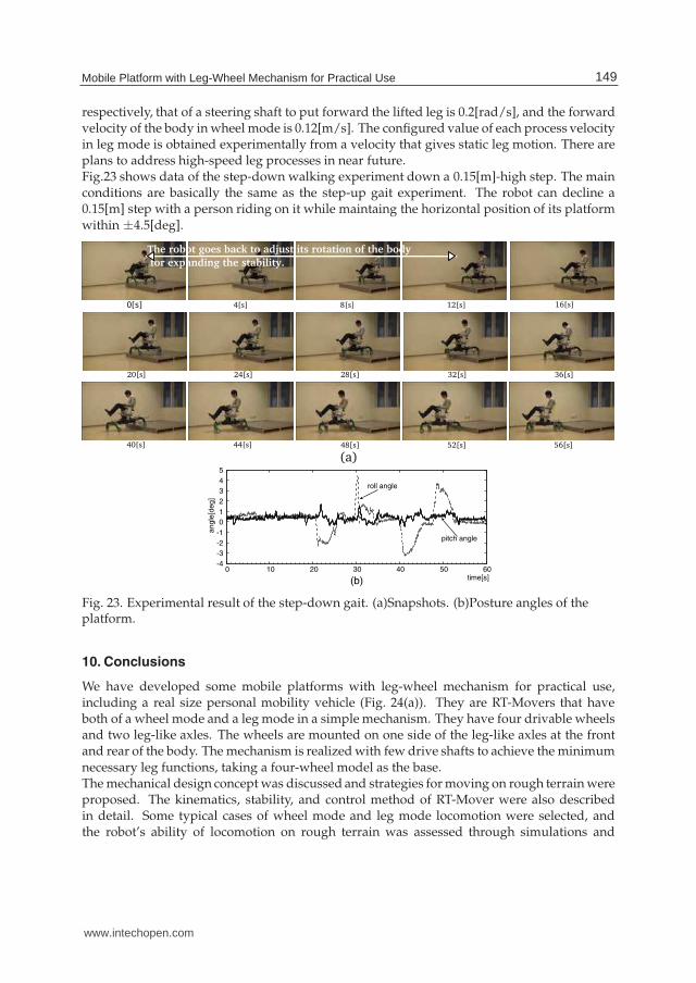
respectively, that of a steering shaft to put forward the lifted leg is 0.2[rad/s], and the forwardvelocity of the body in wheel mode is 0.12[m/s]. The configured value of each process velocityin leg mode is obtained experimentally from a velocity that gives static leg motion. There areplans to address high-speed leg processes in near future.Fig.23 shows data of the step-down walking experiment down a 0.15[m]-high step. The mainconditions are basically the same as the step-up gait experiment. The robot can decline a0.15[m] step with a person riding on it while maintaing the horizontal position of its platformwithin ±4.5[deg].
0[s] 4[s] 8[s] 12[s] 16[s]
20[s] 24[s] 28[s] 32[s] 36[s]
40[s] 44[s]
(a)48[s] 52[s] 56[s]
The robot goes back to adjust its rotation of the body
for expanding the stability.
-4
-3
-2
-1
0
1
2
3
4
5
0 10 20 30 40 50 60
an
gle
[de
g]
time[s]
roll angle
pitch angle
(b)
Fig. 23. Experimental result of the step-down gait. (a)Snapshots. (b)Posture angles of theplatform.
10. Conclusions
We have developed some mobile platforms with leg-wheel mechanism for practical use,including a real size personal mobility vehicle (Fig. 24(a)). They are RT-Movers that haveboth of a wheel mode and a leg mode in a simple mechanism. They have four drivable wheelsand two leg-like axles. The wheels are mounted on one side of the leg-like axles at the frontand rear of the body. The mechanism is realized with few drive shafts to achieve the minimumnecessary leg functions, taking a four-wheel model as the base.The mechanical design concept was discussed and strategies for moving on rough terrain wereproposed. The kinematics, stability, and control method of RT-Mover were also describedin detail. Some typical cases of wheel mode and leg mode locomotion were selected, andthe robot’s ability of locomotion on rough terrain was assessed through simulations and
149Mobile Platform with Leg-Wheel Mechanism for Practical Use
www.intechopen.com
24 Mobile Robot / Book 3
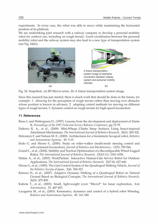
experiments. In every case, the robot was able to move while maintaining the horizontalposition of its platform.We are undertaking joint research with a railway company to develop a personal mobilityrobot for outdoor use, including on rough terrain. Good coordination between the personalmobility robot and the railway system may also lead to a new type of transportation system(see Fig. 24(b)).
(a) (b)
A future transportation
system image of seamless
connection between railway
system and personal mobility
vehicles
Fig. 24. Snapshots. (a) RT-Mover series. (b) A future transportation system image.
Since this research has just started, there is much work that should be done in the future, forexample: 1. allowing for the perception of rough terrain rather than moving over obstacleswhose position is known in advance; 2. adapting control methods for moving on differenttypes of rough terrain; 3. dynamic control on rough terrain for high-speed locomotion.
11. References
Bares J. and Wettergreen D., (1997). Lessons from the development and deployment of DanteII, Proceedings of the 1997 Field and Service Robotics Conference, pp.72-79.
Daltorio K. A., et al., (2009). Mini-Whegs Climbs Steep Surfaces Using Insect-inspiredAttachment Mechanisms, The International Journal of Robotics Research, 28(2): 285-302.
Delcomyn F. and Nelson M. E., (2000). Architectures for a biomimetic hexapod robot, Roboticsand Autonomous Systems, 30: 5-15.
Endo G. and Hirose S., (2000). Study on roller-walker (multi-mode steering control andself-contained locomotion), Journal of Robotics and Mechatronics, 12(5): 559-566.
Grand C., et al., (2004). Stability and Traction Optimization of a Reconfigurable Wheel-LeggedRobot, The International Journal of Robotics Research, 23(10-11): 1041-1058.
Halme A., et al., (2003). WorkPartner: Interactive Human-Like Service Robot for OutdoorApplications, The International Journal of Robotics Research, 22(7-8): 627-640.
Hirose S., et al., (1985). The Gait Control System of the Quadruped Walking Vehicle, Journal ofthe Robotics Society of Japan, 3(4): 304-323.
Kimura H., et al., (2007). Adaptive Dynamic Walking of a Quadruped Robot on NaturalGround Based on Biological Concepts, The International Journal of Robotics Research,26(5): 475-490.
Kubota T., et al., (2003). Small, light-weight rover ”Micro5” for lunar exploration, ActaAstronautica, 52: 447-453.
Lacagnina M., et al., (2003). Kinematics, dynamics and control of a hybrid robot Wheeleg,Robotics and Autonomous Systems, 45: 161-180.
150 Mobile Robots – Current Trends
www.intechopen.com
Mobile Platform with Leg-Wheel Mechanism
for Practical Use 25
Lauria M., et al., (1998). Design and control of an innovative micro-rover, Proceedings of theFifth ESA Workshop on Advanced Space Technologies for Robotics and Automation, TheNetherlands, 1998.
Morales R., et al., (2006). Kinematic Model of a New Staircase Climbing Wheelchair and itsExperimental Validation, The International Journal of Robotics Research, 25(9): 825-841.
Nakajima S., (2011). RT-Mover: a rough terrain mobile robot with a simpleleg-wheel hybrid mechanism, The International Journal of Robotics Research,doi:10.1177/0278364911405697 .
Nakajima S., (2011). Development of a Personal Mobility Robot for Rough Terrain, Proceedingsof the 14th CLAWAR, accepted.
Nakajima S. and Nakano E., (2008a). Adaptive Gait for Large Rough Terrain of a Leg-wheelRobot (First Report: Gait Strategy), Journal of Robotics and Mechatronics, 20(5):801-805.
Nakajima S. and Nakano E., (2008b). Adaptive Gait for Large Rough Terrain of a Leg-wheelRobot (Second Report:Step-Up Gait), Journal of Robotics and Mechatronics, 20(6):913-920.
Nakajima S. and Nakano E., (2009a). Adaptive Gait for Large Rough Terrain of a Leg-wheelRobot (Third Report: Step-Down Gait), Journal of Robotics and Mechatronics, 21(1):12-19.
Nakajima S. and Nakano E., (2009b). Adaptive Gait for Large Rough Terrain of a Leg-wheelRobot (Fourth Report: Step-Over Gait), Journal of Robotics and Mechatronics, 21(2):285-292.
Nakajima S. and Nakano E., (2009c). Adaptive Gait for Large Rough Terrain of a Leg-wheelRobot (Fifth Report: Integrated Gait), Journal of Robotics and Mechatronics, 21(3):419-426.
Quaglia G., et al., (2010). The Epi.q-1 Hybrid Mobile Robot, The International Journal of RoboticsResearch, 29(1): 81-91.
Quinn R. D., et al., (2003). Parallel Complementary Strategies for Implementing BiologicalPrinciples into Mobile Robots, The International Journal of Robotics Research, 22(3):169-186.
Sato M., et al., (2007). An Environmental Adaptive Control System of a Wheel Type MobileRobot for the Rough Terrain Movement, Proceedings of the 2007 IEEE/RSJ InternationalConference on Intelligent Robots and Systems, pp.3962-3967.
Siegwart R., et al., (2002). Innovative design for wheeled locomotion in rough terrain, Roboticsand Autonomous Systems, 40: 151-162.
Six K. and Kecskem’ethy A., (1999). Steering properties of a combined wheeled and leggedstriding excavator, Proceedings of the 10th World Congress on the Theory of Machines andMechanisms, pp.135-140.
Smith J. A., et al., (2006). PAW: a Hybrid Wheeled-Leg Robot, Proceedings of the 2006 IEEEInternational Conference on Robotics and Automation, pp.4043-4048.
Song S. M. and Waldron K. J., (1989). Machines That Walk: The Adaptive Suspension Vehicle,MIT Press.
Thueer T., et al., (2006). CRAB-Exploration rover with advanced obstacle negotiationcapabilities, Proceedings of the 9th ESA Workshop on Advanced Space Technologies forRobotics and Automation, pp.1-8.
Volpe R., et al., (1997). Rocky 7: A next generation Mars rover prototype, Journal of AdvancedRobotics, 11(4): 341-358.
151Mobile Platform with Leg-Wheel Mechanism for Practical Use
www.intechopen.com
26 Mobile Robot / Book 3
Winnendael M. V., et al., (1999). Nanokhod micro-rover heading towards Mars, Proceedingsof the Fifth International Symposium on Artificial Intelligence, Robotics and Automation inSpace, pp.69-76.
Yoneda K., (2007). Light Weight Quadruped with Nine Actuators, Journal of Robotics andMechatronics, 19(2): 160-165.
Yoneda K., et al., (2009). High-grip Stair Climber with Powder-filled Belts, The InternationalJournal of Robotics Research, 28(1): 81-89.
Yuan J. and Hirose S., (2004). Research on Leg-wheel Hybrid Stair Climbing Robot,Zero Carrier, Proceedings of the 2004 IEEE International Conference on Robotics andBiomimetics, pp.1-6.
152 Mobile Robots – Current Trends
www.intechopen.com
Mobile Robots - Current TrendsEdited by Dr. Zoran Gacovski
ISBN 978-953-307-716-1Hard cover, 402 pagesPublisher InTechPublished online 26, October, 2011Published in print edition October, 2011
InTech EuropeUniversity Campus STeP Ri Slavka Krautzeka 83/A 51000 Rijeka, Croatia Phone: +385 (51) 770 447 Fax: +385 (51) 686 166www.intechopen.com
InTech ChinaUnit 405, Office Block, Hotel Equatorial Shanghai No.65, Yan An Road (West), Shanghai, 200040, China
Phone: +86-21-62489820 Fax: +86-21-62489821
This book consists of 18 chapters divided in four sections: Robots for Educational Purposes, Health-Care andMedical Robots, Hardware - State of the Art, and Localization and Navigation. In the first section, there arefour chapters covering autonomous mobile robot Emmy III, KCLBOT - mobile nonholonomic robot, andgeneral overview of educational mobile robots. In the second section, the following themes are covered:walking support robots, control system for wheelchairs, leg-wheel mechanism as a mobile platform, micromobile robot for abdominal use, and the influence of the robot size in the psychological treatment. In the thirdsection, there are chapters about I2C bus system, vertical displacement service robots, quadruped robots -kinematics and dynamics model and Epi.q (hybrid) robots. Finally, in the last section, the following topics arecovered: skid-steered vehicles, robotic exploration (new place recognition), omnidirectional mobile robots, ball-wheel mobile robots, and planetary wheeled mobile robots.
How to referenceIn order to correctly reference this scholarly work, feel free to copy and paste the following:
Shuro Nakajima (2011). Mobile Platform with Leg-Wheel Mechanism for Practical Use, Mobile Robots -Current Trends, Dr. Zoran Gacovski (Ed.), ISBN: 978-953-307-716-1, InTech, Available from:http://www.intechopen.com/books/mobile-robots-current-trends/mobile-platform-with-leg-wheel-mechanism-for-practical-use


![Design and Basic Experiments of a Transformable Wheel ...vigir.missouri.edu/~gdesouza/Research/Conference... · AZIMUT [9], HYBRID Robot [10], wheel-track-leg Robot [11], and miniature](https://img.pdfslide.net/doc/110x75/60db3c13ce792c75e06ec75b/design-and-basic-experiments-of-a-transformable-wheel-vigir-gdesouzaresearchconference.jpg)