Embed Size (px)
Citation preview
Instruction Manual
Rough-In, Assembly, Installation, Operation, & Maintenance
Sage Systems Standalone Models High Pressure Sanitizing Systems Models SW- and SM- Table of Contents
Safety Introduction 2 System Components 3 Rough-In 4 Assembly & Installation 5 Operation 8 Troubleshooting Problems 13 Troubleshooting Solutions 13 Maintenance 16 Service 17
Warranty
Sage Systems warrants to the original purchaser, other than for purposes of resale, that all Sage Systems products shall be free from defect in workmanship and materials for a period of one (1) year from installation. Under no circumstance shall Sage Systems be liable to the purchaser or any other person for any loss of use of the product or any special or consequential costs, expenses, or damages whatsoever arising out of Breach of Warranty, Breach of Contract, or otherwise incurred by the purchaser or any other user. Liability under this warranty is limited to Sage Systems or Sage Systems authorized repair or replacement of the material found to be defective, after proper examination by Sage Systems authorized personnel during the warranty period. Before any in field warranty service can be performed, the owner must contact our dedicated Sage Service Technician at USA 888-757-3784 or Rest of the World +44 (0) 1793 603488. This warranty does not cover products that have been altered or modified after purchase, or for defects caused by physical abuse or misuse of the product. Any express warranty not provided herein and any remedy for Breach of Contract which but for this provision might arise by implication or operation of law, are hereby excluded and disclaimed. Any implied warranties of merchantability or fitness for a particular purpose are limited in duration to the above one year period. Some states do not allow limitations on how long an implied warranty lasts, or the exclusion or limitation of incidental or consequential damage. Therefore, all the above limitations or exclusions appearing herein may not be permitted. Local statutes should be consulted with respect thereto, or to any other rights which your state statutes may specifically confer on the purchaser.
Sage Systems Technician USA/CANADA 888-757-3784 Rest of the World +44 (0)1793 603488 Page 2 of 24
Safety Introduction
Warning! When using this product, basic precautions should always be followed, including the following Read all instructions before using the product. To reduce the risk of injury, close supervision is necessary if a product is used near children. Know how to stop the product and bleed the pressure quickly. Be thoroughly familiar with the controls. Stay alert, and watch what you are doing. Do not operate the product when you are fatigued or under the influence of alcohol or drugs. Keep the operating area clear of all persons Do not overreach or stand on unstable supports. Keep good footing and balance at all times. Follow the maintenance instructions specified in the manual. This product requires the use of a Ground Fault Circuit Interrupter (GFCI) built into the supplying power line. If replacement of electrical components is needed, use only identical replacement parts.
Warning! Risk of infection or injury – Do not direct discharge at persons.
Grounding Instructions This product must be grounded. If it should malfunction or break down, grounding provides a path of least resistance for electrical current to reduce the risk of electric shock.
Danger! Improper connection of the equipment grounding conductor can result in a risk of electrocution. Check with a qualified electrician or service personnel if you are in doubt as to whether the power supply line is properly grounded.
Ground Fault Circuit Interrupter Protection This pressure washer requires the installation of a Ground Fault Circuit Interrupter (GFCI) onto the incoming power lines. This device provides additional protection from the risk of electric shock. Consult a qualified electrician should repair or replacement of the GFCI become necessary.
Warning! To reduce the risk of electrocution, keep all wires, switches, and wire connections free of excess exposure to water and in good condition. Do not touch electrical systems with wet hands.
Caution! Consult with the factory before using a nozzle other than the one provided with this machine.
Caution! Do not use with an Extension Lead.
Save these Instructions
Sage Systems Technician USA/CANADA 888-757-3784 Rest of the World +44 (0)1793 603488 Page 3 of 24
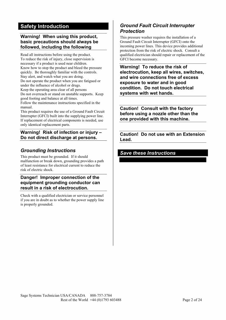
System Components Components included with Sage System Standalone models SW & SM, to be assembled and installed.
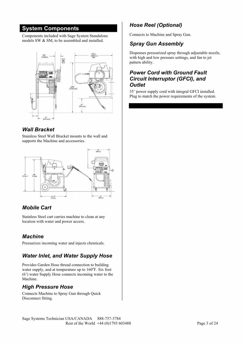
Wall Bracket Stainless Steel Wall Bracket mounts to the wall and supports the Machine and accessories.
Mobile Cart Stainless Steel cart carries machine to clean at any location with water and power access.
Machine Pressurizes incoming water and injects chemicals.
Water Inlet, and Water Supply Hose Provides Garden Hose thread connection to building water supply, and at temperature up to 160oF. Six foot (6’) water Supply Hose connects incoming water to the Machine.
High Pressure Hose Connects Machine to Spray Gun through Quick Disconnect fitting.
Hose Reel (Optional) Connects to Machine and Spray Gun.5
Spray Gun Assembly 7 Dispenses pressurized spray through adjustable nozzle, with high and low pressure settings, and fan to jet pattern ability.
Power Cord with Ground Fault Circuit Interruptor (GFCI), and Outlet 35’ power supply cord with integral GFCI installed. Plug to match the power requirements of the system.

Sage Systems Technician USA/CANADA 888-757-3784 Rest of the World +44 (0)1793 603488 Page 4 of 24
Rough-In This section is intended to give general guidelines for site preparation and rough-in. Dimensions or suggested locations described in this section are based on standard mounting specifications and may vary to meet special installation requirements or conditions. All rough-in items should be completed before walls, floors, or ceilings are finished.
Wall Bracket The Wall Bracket will support approximately 200 pounds (91 kg) of Machine and accessories. Also, the Wall Bracket has four 3/8” holes spaced in a rectangular pattern 16 in (40.6 cm) wide and 12 in (30.5 cm) high.
The wall and wall supports should be constructed to accommodate these dimensions and weight. The lowest two holes should be at least 16 in (54 cm) above the floor, to insure enough clearance for chemical containers. Wood studs on 16 in (40.6 cm) centers will accept four 5/16 in x 6 in long (8 mm x 15 cm long) lag screws. Masonry surfaces will accept four 5/16 in (8 mm) anchor bolts.
Machine Electrical All machines require one dedicated 20 amp appliance circuit for 115 Volt 60Hertz, or one dedicated 10 amp appliance circuit for either the 230 Volt 50 Hertz or 230 Volt 60 Hertz systems.
Machine Plumbing All machines require a water connection with shut-off ability and a ¾” garden hose thread outlet.
The machine requires a minimum of 4.0 gpm (15 lpm) at no less than 30 psi (2 bar). Locate the Sill Faucet approximately 6 in (15cm) left of wall mounted Machines and 12 in (30cm) above the floor.
Recommended water temperature may vary depending on the chemical(s) selected. However, typical soap and sanitizing solutions work best with water between 120oF and 150oF. Maximum water temperature for all Sage Systems machines is 160oF. A single temperature faucet is acceptable if the provided water is less than 160oF, and if the provided water temperature is appropriate for all chemicals desired. In some cases, a separate tempering device before the faucet may be necessary. A mixing faucet may be required if the provided water temperature needs to vary depending on the application. In these cases, the maximum hot water temperature supplied to the mixing faucet should not exceed 160oF. Also, a thermometer to measure the outlet water’s temperature is suggested.
Note! Some chemicals may lose their effectiveness if mixed with water too hot. Check with your probable chemical suppliers for the optimal application temperature for each set of circumstances.
3 options 1 160°F (71°C) water straight to a sill faucet 2 180°F (82°C) water mixed through a temperature
control device to a sill faucet 3 160°F (77°C) water and cold water mixed at a two
handle faucet
Sage Systems Technician USA/CANADA 888-757-3784 Rest of the World +44 (0)1793 603488 Page 5 of 24
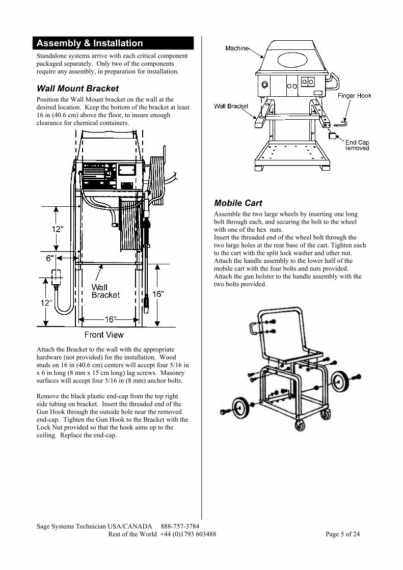
Assembly & Installation Standalone systems arrive with each critical component packaged separately. Only two of the components require any assembly, in preparation for installation.
Wall Mount Bracket Position the Wall Mount bracket on the wall at the desired location. Keep the bottom of the bracket at least 16 in (40.6 cm) above the floor, to insure enough clearance for chemical containers.
Attach the Bracket to the wall with the appropriate hardware (not provided) for the installation. Wood studs on 16 in (40.6 cm) centers will accept four 5/16 in x 6 in long (8 mm x 15 cm long) lag screws. Masonry surfaces will accept four 5/16 in (8 mm) anchor bolts. Remove the black plastic end-cap from the top right side tubing on bracket. Insert the threaded end of the Gun Hook through the outside hole near the removed end-cap. Tighten the Gun Hook to the Bracket with the Lock Nut provided so that the hook aims up to the ceiling. Replace the end-cap.
Mobile Cart Assemble the two large wheels by inserting one long bolt through each, and securing the bolt to the wheel with one of the hex nuts. Insert the threaded end of the wheel bolt through the two large holes at the rear base of the cart. Tighten each to the cart with the split lock washer and other nut. Attach the handle assembly to the lower half of the mobile cart with the four bolts and nuts provided. Attach the gun holster to the handle assembly with the two bolts provided.
Sage Systems Technician USA/CANADA 888-757-3784 Rest of the World +44 (0)1793 603488 Page 6 of 24
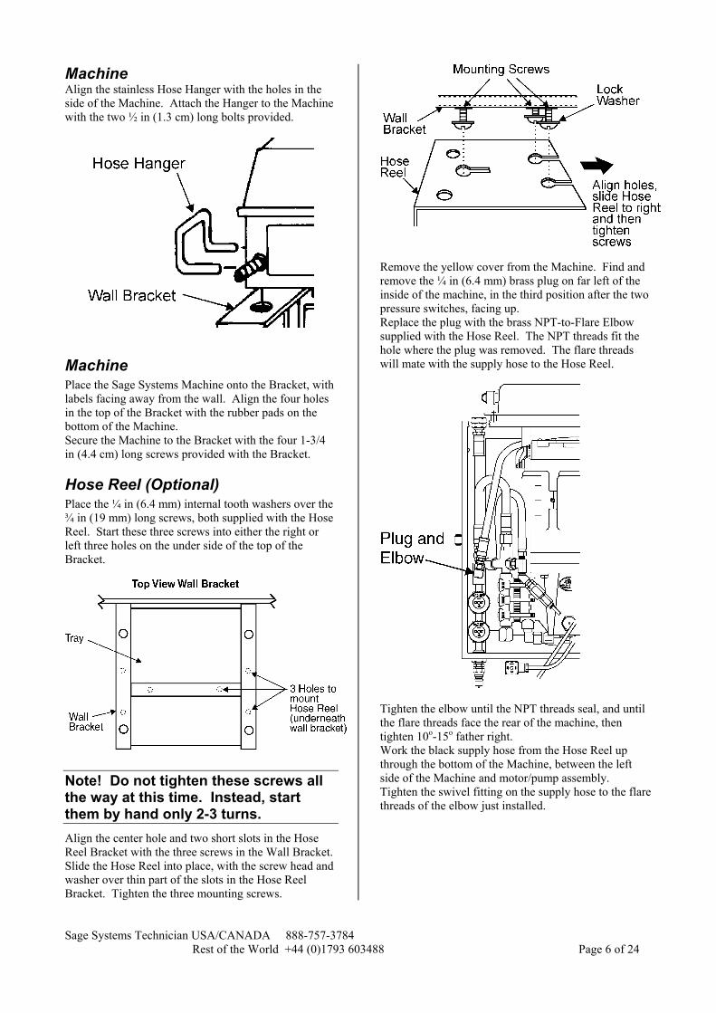
Machine Align the stainless Hose Hanger with the holes in the side of the Machine. Attach the Hanger to the Machine with the two ½ in (1.3 cm) long bolts provided.
Machine Place the Sage Systems Machine onto the Bracket, with labels facing away from the wall. Align the four holes in the top of the Bracket with the rubber pads on the bottom of the Machine. Secure the Machine to the Bracket with the four 1-3/4 in (4.4 cm) long screws provided with the Bracket.
Hose Reel (Optional) Place the ¼ in (6.4 mm) internal tooth washers over the ¾ in (19 mm) long screws, both supplied with the Hose Reel. Start these three screws into either the right or left three holes on the under side of the top of the Bracket.
Note! Do not tighten these screws all the way at this time. Instead, start them by hand only 2-3 turns. Align the center hole and two short slots in the Hose Reel Bracket with the three screws in the Wall Bracket. Slide the Hose Reel into place, with the screw head and washer over thin part of the slots in the Hose Reel Bracket. Tighten the three mounting screws.
Remove the yellow cover from the Machine. Find and remove the ¼ in (6.4 mm) brass plug on far left of the inside of the machine, in the third position after the two pressure switches, facing up. Replace the plug with the brass NPT-to-Flare Elbow supplied with the Hose Reel. The NPT threads fit the hole where the plug was removed. The flare threads will mate with the supply hose to the Hose Reel.
Tighten the elbow until the NPT threads seal, and until the flare threads face the rear of the machine, then tighten 10o-15o father right. Work the black supply hose from the Hose Reel up through the bottom of the Machine, between the left side of the Machine and motor/pump assembly. Tighten the swivel fitting on the supply hose to the flare threads of the elbow just installed.
Sage Systems Technician USA/CANADA 888-757-3784 Rest of the World +44 (0)1793 603488 Page 7 of 24
Back to the Machine Water Inlet Attach the 6 ft (1.8 m) water supply hose to the nearby Sill Faucet with ¾ in (1.9 cm) garden hose thread.
Note! The machine must not be piped directly to the water source. The resilience of the water supply hose is required to absorb water shock. Otherwise, the piping system for the building may shake and rattle under normal operation. Turn on the Sill Faucet. The float tank on the back of the Machine should fill with water, and the shut off.
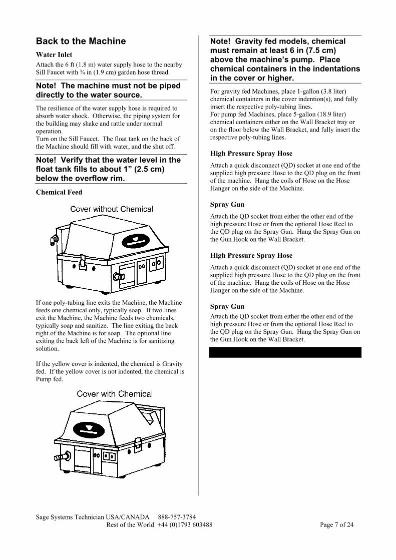
Note! Verify that the water level in the float tank fills to about 1” (2.5 cm) below the overflow rim. Chemical Feed
If one poly-tubing line exits the Machine, the Machine feeds one chemical only, typically soap. If two lines exit the Machine, the Machine feeds two chemicals, typically soap and sanitize. The line exiting the back right of the Machine is for soap. The optional line exiting the back left of the Machine is for sanitizing solution. If the yellow cover is indented, the chemical is Gravity fed. If the yellow cover is not indented, the chemical is Pump fed.
Note! Gravity fed models, chemical must remain at least 6 in (7.5 cm) above the machine’s pump. Place chemical containers in the indentations in the cover or higher. For gravity fed Machines, place 1-gallon (3.8 liter) chemical containers in the cover indention(s), and fully insert the respective poly-tubing lines. For pump fed Machines, place 5-gallon (18.9 liter) chemical containers either on the Wall Bracket tray or on the floor below the Wall Bracket, and fully insert the respective poly-tubing lines.
High Pressure Spray Hose Attach a quick disconnect (QD) socket at one end of the supplied high pressure Hose to the QD plug on the front of the machine. Hang the coils of Hose on the Hose Hanger on the side of the Machine.
Spray Gun Attach the QD socket from either the other end of the high pressure Hose or from the optional Hose Reel to the QD plug on the Spray Gun. Hang the Spray Gun on the Gun Hook on the Wall Bracket.
Sage Systems Technician USA/CANADA 888-757-3784 Rest of the World +44 (0)1793 603488 Page 8 of 24
Operation
Machine Preparation
Warning! Check oil level of pump before operating. Check the oil level, through the site hole in the front of the machine. The oil level should bisect the red dot on the front of the pump when the Machine is not running. Oil should not be too low or too high. If oil level is too low, add just enough to bisect the red dot. If oil level is too high, see “Oil level has caused pump contamination” in the Troubleshooting section of this manual.
Caution! Before using machine, remove black solid plug from top of the pump, and replace it with red vented plug, shipped in a plastic bag near pump. Insert soap and/or sanitize polytubing(s) into the chemical container. Gravity fed systems need 1 gallon (3.8 liter) containers placed in indentations in the cover. Pump fed system can use any size container, placed nearby either above or below the Machine.
Caution! Do not operate machine without cover in place Open the Sill faucet and check for the float tank to fill to about 1” below the overflow line. Once the float tank is full, the unit is now ready to operate.
Caution! To prevent damage to the pump, water must be turned on and the float tank should be properly filled before starting the Machine.
Sage Systems Technician USA/CANADA 888-757-3784 Rest of the World +44 (0)1793 603488 Page 9 of 24
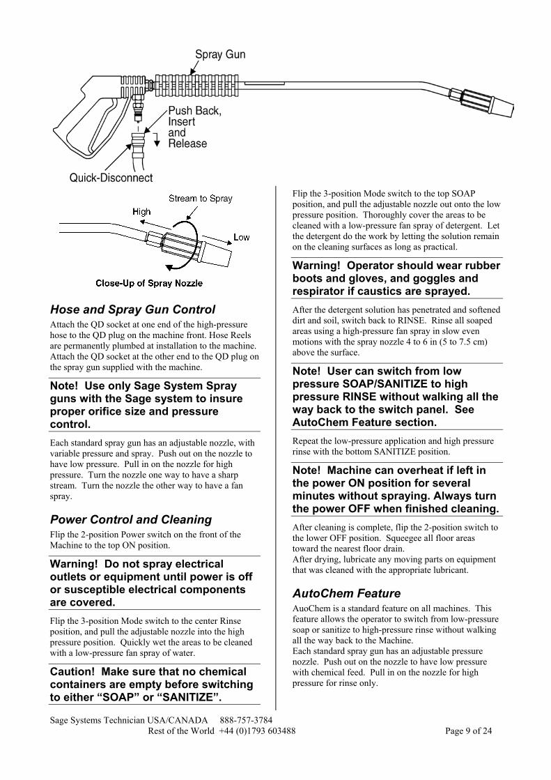
Hose and Spray Gun Control Attach the QD socket at one end of the high-pressure hose to the QD plug on the machine front. Hose Reels are permanently plumbed at installation to the machine. Attach the QD socket at the other end to the QD plug on the spray gun supplied with the machine.
Note! Use only Sage System Spray guns with the Sage system to insure proper orifice size and pressure control. Each standard spray gun has an adjustable nozzle, with variable pressure and spray. Push out on the nozzle to have low pressure. Pull in on the nozzle for high pressure. Turn the nozzle one way to have a sharp stream. Turn the nozzle the other way to have a fan spray.
Power Control and Cleaning Flip the 2-position Power switch on the front of the Machine to the top ON position.
Warning! Do not spray electrical outlets or equipment until power is off or susceptible electrical components are covered. Flip the 3-position Mode switch to the center Rinse position, and pull the adjustable nozzle into the high pressure position. Quickly wet the areas to be cleaned with a low-pressure fan spray of water.
Caution! Make sure that no chemical containers are empty before switching to either “SOAP” or “SANITIZE”.
Flip the 3-position Mode switch to the top SOAP position, and pull the adjustable nozzle out onto the low pressure position. Thoroughly cover the areas to be cleaned with a low-pressure fan spray of detergent. Let the detergent do the work by letting the solution remain on the cleaning surfaces as long as practical.
Warning! Operator should wear rubber boots and gloves, and goggles and respirator if caustics are sprayed. After the detergent solution has penetrated and softened dirt and soil, switch back to RINSE. Rinse all soaped areas using a high-pressure fan spray in slow even motions with the spray nozzle 4 to 6 in (5 to 7.5 cm) above the surface.
Note! User can switch from low pressure SOAP/SANITIZE to high pressure RINSE without walking all the way back to the switch panel. See AutoChem Feature section. Repeat the low-pressure application and high pressure rinse with the bottom SANITIZE position.
Note! Machine can overheat if left in the power ON position for several minutes without spraying. Always turn the power OFF when finished cleaning. After cleaning is complete, flip the 2-position switch to the lower OFF position. Squeegee all floor areas toward the nearest floor drain. After drying, lubricate any moving parts on equipment that was cleaned with the appropriate lubricant.
AutoChem Feature AuoChem is a standard feature on all machines. This feature allows the operator to switch from low-pressure soap or sanitize to high-pressure rinse without walking all the way back to the Machine. Each standard spray gun has an adjustable pressure nozzle. Push out on the nozzle to have low pressure with chemical feed. Pull in on the nozzle for high pressure for rinse only.
Sage Systems Technician USA/CANADA 888-757-3784 Rest of the World +44 (0)1793 603488 Page 10 of 24
AutoChem limits soap and sanitize application to the low-pressure nozzle setting only. This reduces overspray of chemicals, which is safer for the operator and better in sensitive foodservice establishments. In the SOAP mode, soap will feed only in the low pressure setting. The same is true for sanitize. Neither soap nor sanitize should feed when in high pressure or unloaded (with the trigger released).
Chemical Selection
Warning! Compare any active chemical ingredients against the Cat Pump Chemical Compatibility Chart attached as an appendix to this manual. Most industrial liquid soap and sanitizers are compatible with the Sage Systems. However, some may cause or accelerate pump damage. Also, when selecting a chemical, the following precautions should be observed.
Note! Avoid detergents that tend to precipitate hard water elements These accelerate build up in pump and lines. These soaps will create a need for more frequent deliming than is convenient. Instead, use a detergent that is formulated to hold hard water elements in suspension to keep the inside of the pump and lines maintaining their “as new” appearance.
Note! Use only non-foaming non-detergent sanitizers. Foaming products should not be fed through the Sage System. Instead, for applications where a foaming chemical is required, use the Sage Systems Foamer Spray Gun assembly. This device mixes the chemical with water at an adjustable rate at the spray gun, isolating the expansion of the foam far downstream from the pump.
Caution! Avoid chlorine-based solutions. These can produce dangerous fumes when in contact with acid solutions. Chlorine solutions can also attack brass or stainless steel in strong solutions, or unless specially formulated.
Caution! Some concentrated detergents or sanitizers may be toxic. Follow the directions on the container label in handling and dispensing.
Caution! Avoid breathing the spray mist of chemicals formulated with caustics.
Always wear goggles, boots, gloves, respirator, or any other safety equipment recommended by the chemical manufacturer when handling or dispensing their product through the Sage System.
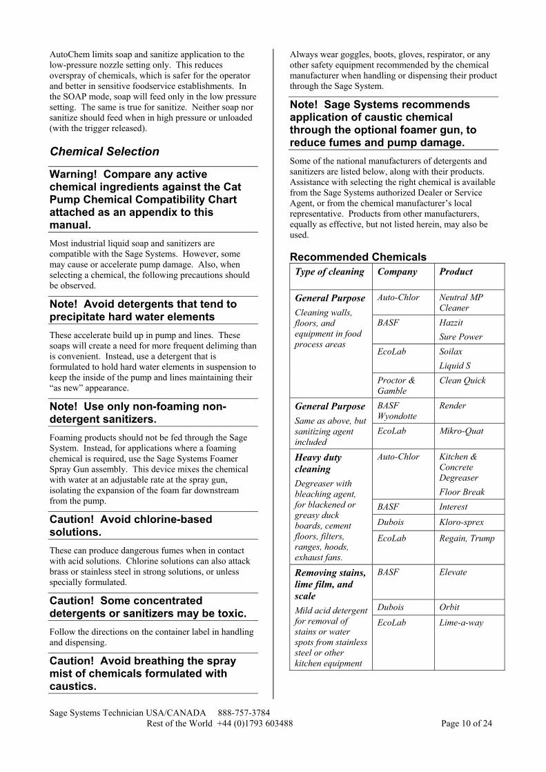
Note! Sage Systems recommends application of caustic chemical through the optional foamer gun, to reduce fumes and pump damage. Some of the national manufacturers of detergents and sanitizers are listed below, along with their products. Assistance with selecting the right chemical is available from the Sage Systems authorized Dealer or Service Agent, or from the chemical manufacturer’s local representative. Products from other manufacturers, equally as effective, but not listed herein, may also be used. Recommended Chemicals Type of cleaning Company Product
Auto-Chlor Neutral MP Cleaner
BASF Hazzit Sure Power
EcoLab Soilax Liquid S
General Purpose Cleaning walls, floors, and equipment in food process areas
Proctor & Gamble
Clean Quick
BASF Wyondotte
Render General Purpose Same as above, but sanitizing agent included
EcoLab Mikro-Quat
Auto-Chlor Kitchen & Concrete Degreaser Floor Break
BASF Interest
Dubois Kloro-sprex
Heavy duty cleaning Degreaser with bleaching agent, for blackened or greasy duck boards, cement floors, filters, ranges, hoods, exhaust fans.
EcoLab Regain, Trump
BASF Elevate
Dubois Orbit
Removing stains, lime film, and scale Mild acid detergent for removal of stains or water spots from stainless steel or other kitchen equipment
EcoLab Lime-a-way
Sage Systems Technician USA/CANADA 888-757-3784 Rest of the World +44 (0)1793 603488 Page 11 of 24
Auto-Chlor Solution QA Sanitizing with germicide Non foaming detergent or cleaning agent to sanitize food handling facilities and equipment after washing
Dubois D-trol
Chemical Mix Ratio All Sage Systems machines output a maximum of 2.9 gpm (11.0 lpm). The actual pump output may vary, depending on the power specified and supplied to the machine, and the efficiency of the pump and motor over time. When calculating mix ratios, assume 2.9 gpm (11.0 lpm) total output, most of which is water, and some of which is the fed chemical. Valve and pump settings are approximate, based on typical installation and feed device manufacturer’s specifications. For field verification of a setting, place the chemical feed tube in a measured container or graduated cylinder. Time the feed rate of the chemical. Compare the feed rate to the 2.9 gpm (11.0 lpm) pump output. Adjust the feed rate accordingly to mix the specified volume of chemical with the
Note! Gravity fed models, place chemical containers in the indentations in the cover. Pump fed models, place containers underneath machine, preferably on its tray.
Gravity Fed, Solenoid Valves The solenoid valve is a white bodied device with a larger green head, and a blue adjustment knob. The blue knob has approximately 11 full turns of adjustment. Tighten the knob (clockwise) to reduce or loosen (counter clockwise) to increase the feed rate. Feed rate will be somewhat dependent on the height of the chemical above the valve, and the level of chemical in the container.
Note! For gravity fed, solenoid valve machines, the chemical must remain at least 6 in (7.5 cm) above the machine’s pump.
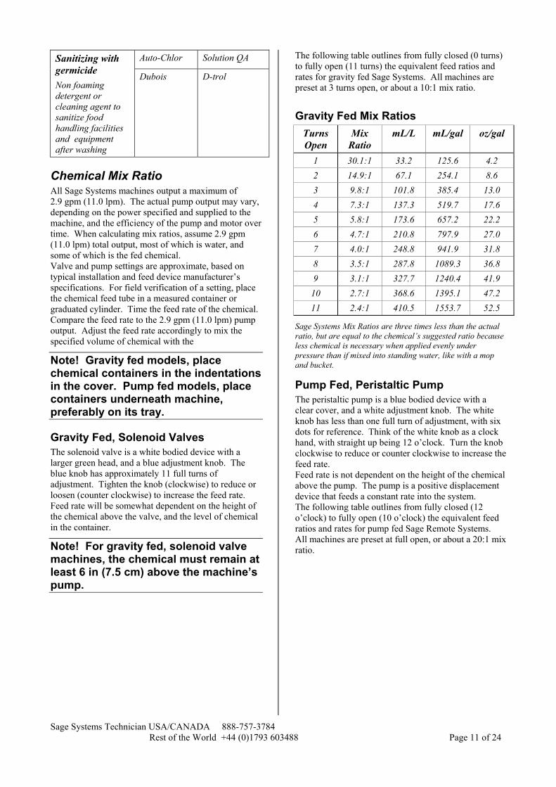
The following table outlines from fully closed (0 turns) to fully open (11 turns) the equivalent feed ratios and rates for gravity fed Sage Systems. All machines are preset at 3 turns open, or about a 10:1 mix ratio.
Gravity Fed Mix Ratios Turns Open
Mix Ratio
mL/L mL/gal oz/gal
1 30.1:1 33.2 125.6 4.2 2 14.9:1 67.1 254.1 8.6 3 9.8:1 101.8 385.4 13.0 4 7.3:1 137.3 519.7 17.6 5 5.8:1 173.6 657.2 22.2 6 4.7:1 210.8 797.9 27.0 7 4.0:1 248.8 941.9 31.8 8 3.5:1 287.8 1089.3 36.8 9 3.1:1 327.7 1240.4 41.9
10 2.7:1 368.6 1395.1 47.2 11 2.4:1 410.5 1553.7 52.5
Sage Systems Mix Ratios are three times less than the actual ratio, but are equal to the chemical’s suggested ratio because less chemical is necessary when applied evenly under pressure than if mixed into standing water, like with a mop and bucket.
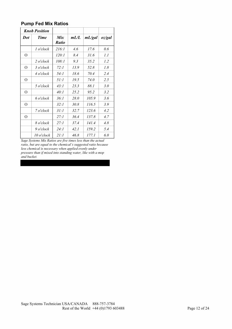
Pump Fed, Peristaltic Pump The peristaltic pump is a blue bodied device with a clear cover, and a white adjustment knob. The white knob has less than one full turn of adjustment, with six dots for reference. Think of the white knob as a clock hand, with straight up being 12 o’clock. Turn the knob clockwise to reduce or counter clockwise to increase the feed rate. Feed rate is not dependent on the height of the chemical above the pump. The pump is a positive displacement device that feeds a constant rate into the system. The following table outlines from fully closed (12 o’clock) to fully open (10 o’clock) the equivalent feed ratios and rates for pump fed Sage Remote Systems. All machines are preset at full open, or about a 20:1 mix ratio.
Sage Systems Technician USA/CANADA 888-757-3784 Rest of the World +44 (0)1793 603488 Page 12 of 24
Pump Fed Mix Ratios Knob Position
Dot Time Mix Ratio
mL/L mL/gal oz/gal
1 o'clock 216:1 4.6 17.6 0.6 O 120:1 8.4 31.6 1.1 2 o'clock 108:1 9.3 35.2 1.2
O 3 o'clock 72:1 13.9 52.8 1.8 4 o'clock 54:1 18.6 70.4 2.4
O 51:1 19.5 74.0 2.5 5 o'clock 43:1 23.3 88.1 3.0
O 40:1 25.2 95.2 3.2 6 o'clock 36:1 28.0 105.9 3.6
O 32:1 30.8 116.5 3.9 7 o'clock 31:1 32.7 123.6 4.2
O 27:1 36.4 137.8 4.7 8 o'clock 27:1 37.4 141.4 4.8 9 o'clock 24:1 42.1 159.2 5.4 10 o'clock 21:1 46.8 177.1 6.0
Sage Systems Mix Ratios are five times less than the actual ratio, but are equal to the chemical’s suggested ratio because less chemical is necessary when applied evenly under pressure than if mixed into standing water, like with a mop and bucket.

Sage Systems Technician USA/CANADA 888-757-3784 Rest of the World +44 (0)1793 603488 Page 13 of 24
Troubleshooting Problems
Nothing happens when Machine is switched on • GFCI may need to be reset • Motor needs to be reset • Motor is not operating
Machine starts but immediately stops • Power supply is inadequate
Machine starts with low pressure • Machine is starved for water • Pressure is leaking out of system • Adjustable nozzle issues • Lime build up is hampering the pump • Unloader valve needs adjustment • Pump may need rebuilding
Machine starts with high pressure, but then the pressure drops • Air is entering the system • Machine is starved for water
Machine is loud, shuddering, or vibrating and not producing pressure • Machine is starved for water • Air is entering the system • Temperature relief valve is discharging • Unloader valve needs adjustment
Machine is not dispensing soap or sanitizing agent • Chemical containers are empty • Chemical is too thick or viscous • Solenoid(s) do not have gravity assist • Chemical feed tubing is cracked or leaking • Pressure switch for AutoChem feature needs
adjusting • Chemical feed devices are not functioning properly
Machine is constantly dispensing soap or sanitizing agent • Pressure switch for AutoChem feature needs
adjusting
Machine will only dispense soap or sanitize in low pressure nozzle setting This is normal. It’s called the AutoChem feature, and has some distinct advantages. Please see the Operation section titled AutoChem feature, or the Troubleshooting Solutions section titled… • Pressure switch for AutoChem feature needs
adjusting
Troubleshooting Solutions
GFCI may need to be reset Depress the Reset button on the GFCI and release. Make sure to verify that the supply power is adequate, on a dedicated line with a 20 amp circuit breaker.
Chemical is too thick or viscous Thick, dense, or viscous chemicals may have difficulty flowing through the small diameter poly-tubing. The same chemical may need to be diluted, or may even be available in a thinner form from the supplier. Try running colored water in place of the chemical. If the water draw and mixes with the high pressure spray, your standard chemical may be too thick.
Power supply is inadequate Systems require one dedicated 20 amp appliance circuit for 115 Volt 60 Hertz, or one dedicated 10 amp appliance circuit for of either the 230 Volt 50 Hertz or 230 Volt 60 Hertz systems. Check for the capacity of the circuit or for any other loads on the dedicated line.
Pressure is leaking out of system Determine whether there may be a leak in the Machine itself. Inspect all fittings and hoses in the targeted section of the system for leaks. Tighten or replace if necessary any leaking hoses or fittings.
Adjustable nozzle issues Check the push/pull adjustable nozzle for its position. Pushed out is the low pressure position. Pulled in is the high pressure position. Inspect the high pressure spray pattern. If the pattern appears inconsistent, the nozzle may be worn and may need replacing.
Lime build up is hampering the pump Check for lime build-up on visible fittings in the float tank. Lime build-up may cause the pump to fail. If deliming of the machine was last done over one month ago, use the Sage Systems Deliming assembly and a deliming solution to delime the Machine.
Sage Systems Technician USA/CANADA 888-757-3784 Rest of the World +44 (0)1793 603488 Page 14 of 24
Unloader valve needs adjustment Call the dedicated Sage Technician at (888) 757-3784 for assistance in adjusting the unloader valve, or see the Service section of this manual. Please note, special tools are required for proper Unloader valve adjustment. Sage Systems suggests that only authorized Service Agents set or adjust Unloader Valves.
Motor needs to be reset If the unloader valve is adjusted improperly, the machine may operate at too high a pressure, or may work inefficiently, causing the Machine to draw too many amps for the line. This can create an overload of the motor, which has built in overload protection. The reset button is on the back end of the motor. Make sure to adjust the unloader valve to correct this problem permanently.
Motor is not operating Very rarely are motors worn out to the point of necessary replacement. Any service on a motor is handled through the local authorized Leeson service agent in your area. Refer to the Leeson service guide for a listing.
Machine is starved for water Starving the pump for water will cause serious damage to the pump. Check that the water supply is open, and the float tank is filling with water. Verify that the water supply to the float tank is 4.0 gpm (15 lpm) and 30 psi (2 bar) minimum. If the float tank does not remain sufficiently full to cover the float tank outlet port while the machine is running, the inlet water flow or pressure is insufficient. Observe the water level in the float tank with the Machine on and Spray Gun spraying. The water level should never drain down to the outlet fitting that leads into the Machine. If the water level does drop and does not refill, adjust the float arm for shut off about 1” (2.5 cm) below the overflow rim. Check for kinks or leaks in the water supply hose. Inspect the two filter screens, and clean or replace if necessary. The first is in the supply hose at the float tank. The second is in the in-line water filter inside the Machine, just after the tank feeds through the Machine wall.
Pump may need rebuilding These direct drive pumps can often run smoothly for 5 years, given proper regular maintenance and care. However, worn piston cups, seals, and o-rings can cause a lack of pressure in the pump. Three different pump repair kits are available for pump refurbishment, the Seal kit, Valve kit, and Inlet valve kit. The pump should not ever need to be completely replaced, unless there is significant damage or a crack in the pump housing.
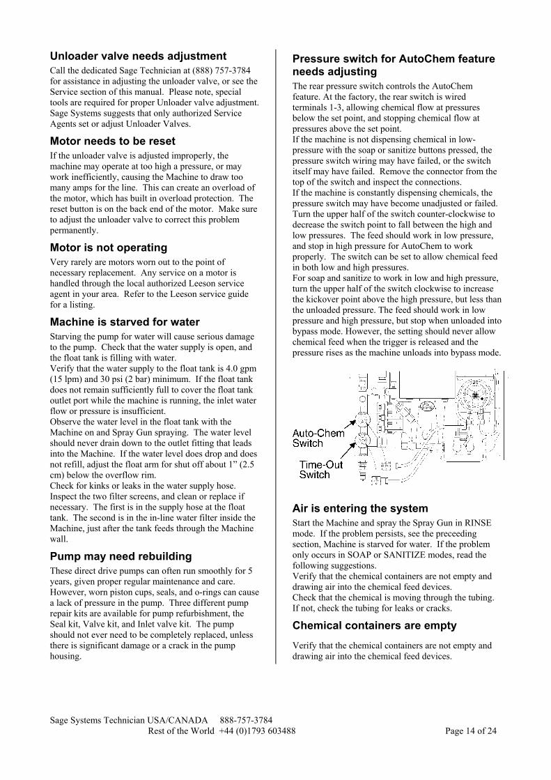
Pressure switch for AutoChem feature needs adjusting The rear pressure switch controls the AutoChem feature. At the factory, the rear switch is wired terminals 1-3, allowing chemical flow at pressures below the set point, and stopping chemical flow at pressures above the set point. If the machine is not dispensing chemical in low-pressure with the soap or sanitize buttons pressed, the pressure switch wiring may have failed, or the switch itself may have failed. Remove the connector from the top of the switch and inspect the connections. If the machine is constantly dispensing chemicals, the pressure switch may have become unadjusted or failed. Turn the upper half of the switch counter-clockwise to decrease the switch point to fall between the high and low pressures. The feed should work in low pressure, and stop in high pressure for AutoChem to work properly. The switch can be set to allow chemical feed in both low and high pressures. For soap and sanitize to work in low and high pressure, turn the upper half of the switch clockwise to increase the kickover point above the high pressure, but less than the unloaded pressure. The feed should work in low pressure and high pressure, but stop when unloaded into bypass mode. However, the setting should never allow chemical feed when the trigger is released and the pressure rises as the machine unloads into bypass mode.
Air is entering the system Start the Machine and spray the Spray Gun in RINSE mode. If the problem persists, see the preceeding section, Machine is starved for water. If the problem only occurs in SOAP or SANITIZE modes, read the following suggestions. Verify that the chemical containers are not empty and drawing air into the chemical feed devices. Check that the chemical is moving through the tubing. If not, check the tubing for leaks or cracks.
Chemical containers are empty
Verify that the chemical containers are not empty and drawing air into the chemical feed devices.
Sage Systems Technician USA/CANADA 888-757-3784 Rest of the World +44 (0)1793 603488 Page 15 of 24
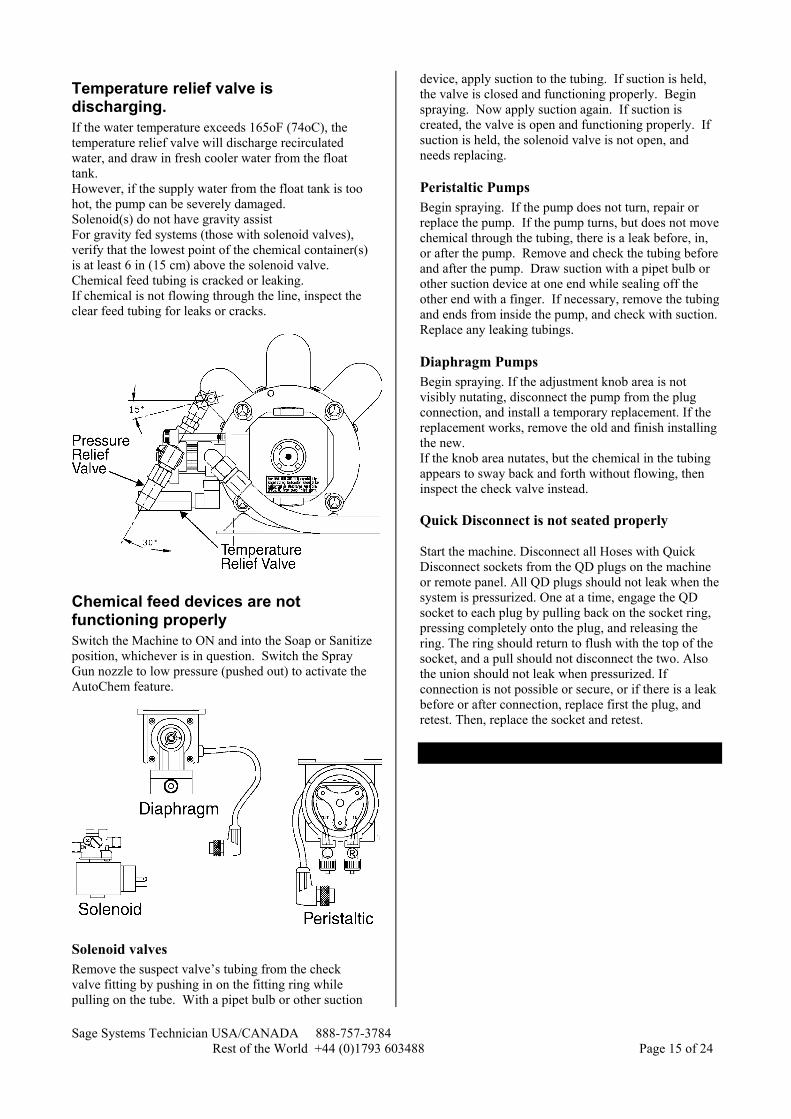
Temperature relief valve is discharging. If the water temperature exceeds 165oF (74oC), the temperature relief valve will discharge recirculated water, and draw in fresh cooler water from the float tank. However, if the supply water from the float tank is too hot, the pump can be severely damaged. Solenoid(s) do not have gravity assist For gravity fed systems (those with solenoid valves), verify that the lowest point of the chemical container(s) is at least 6 in (15 cm) above the solenoid valve. Chemical feed tubing is cracked or leaking. If chemical is not flowing through the line, inspect the clear feed tubing for leaks or cracks.
Chemical feed devices are not functioning properly Switch the Machine to ON and into the Soap or Sanitize position, whichever is in question. Switch the Spray Gun nozzle to low pressure (pushed out) to activate the AutoChem feature.
Solenoid valves Remove the suspect valve’s tubing from the check valve fitting by pushing in on the fitting ring while pulling on the tube. With a pipet bulb or other suction
device, apply suction to the tubing. If suction is held, the valve is closed and functioning properly. Begin spraying. Now apply suction again. If suction is created, the valve is open and functioning properly. If suction is held, the solenoid valve is not open, and needs replacing.
Peristaltic Pumps Begin spraying. If the pump does not turn, repair or replace the pump. If the pump turns, but does not move chemical through the tubing, there is a leak before, in, or after the pump. Remove and check the tubing before and after the pump. Draw suction with a pipet bulb or other suction device at one end while sealing off the other end with a finger. If necessary, remove the tubing and ends from inside the pump, and check with suction. Replace any leaking tubings.
Diaphragm Pumps Begin spraying. If the adjustment knob area is not visibly nutating, disconnect the pump from the plug connection, and install a temporary replacement. If the replacement works, remove the old and finish installing the new. If the knob area nutates, but the chemical in the tubing appears to sway back and forth without flowing, then inspect the check valve instead. Quick Disconnect is not seated properly Start the machine. Disconnect all Hoses with Quick Disconnect sockets from the QD plugs on the machine or remote panel. All QD plugs should not leak when the system is pressurized. One at a time, engage the QD socket to each plug by pulling back on the socket ring, pressing completely onto the plug, and releasing the ring. The ring should return to flush with the top of the socket, and a pull should not disconnect the two. Also the union should not leak when pressurized. If connection is not possible or secure, or if there is a leak before or after connection, replace first the plug, and retest. Then, replace the socket and retest.
Sage Systems Technician USA/CANADA 888-757-3784 Rest of the World +44 (0)1793 603488 Page 16 of 24
Maintenance
Every Month Inspect all fittings and hoses for leaks. Tighten or replace if necessary any leaking hoses or fittings. Inspect the float tank. The float valve should open as the water level drops and before the float bottoms in the tank. The float valve should close before the water level fills to the overflow rim. Adjust the float arm at the valve to insure operation as described. Inspect the two filter screens, and clean or replace if necessary. The first is in the supply hose at the float tank. The second is in the in-line water filter inside the Machine, just after the tank feeds through the Machine wall.
Deliming the Machine Remove the cover from the float tank. Shut off the water supply at the sill faucet. Run the machine and spray until the water is drained from the float tank.
Warning! Do not run the Machine dry. Shut off the Machine as soon as the water level in the float tank reaches the outlet fitting that leads into the Machine. Fill the float tank with a de-liming solution. Attach the QD socket of the T&S de-liming assembly to the QD plug on the front of the Machine. Put the wand end of the de-liming assembly into the float tank Start the Machine, and leave it running 15 to 20 minutes. Near the end of this period, with the Machine still running, disconnect and reconnect the QD socket from the plug at the front of the Machine 6 to 8 times. This will activate the bypass unloader valve, and will delime its functioning parts.
Without a Sage de-liming assembly A high-pressure hose and spray gun can substitute for the Sage System de-liming assembly. Remove the nozzle from the end of the spray gun. Attach the QD socket on the high-pressure hose to the QD plug on the front of the Machine and the Spray gun. Insert the open tip of the wand into the float tank. Follow the standard de-liming instructions with this assembly. This process also delimes the Spray Gun, fittings, and nozzle.
Every Three Months Perform all maintenance items suggested for every month.
Changing oil
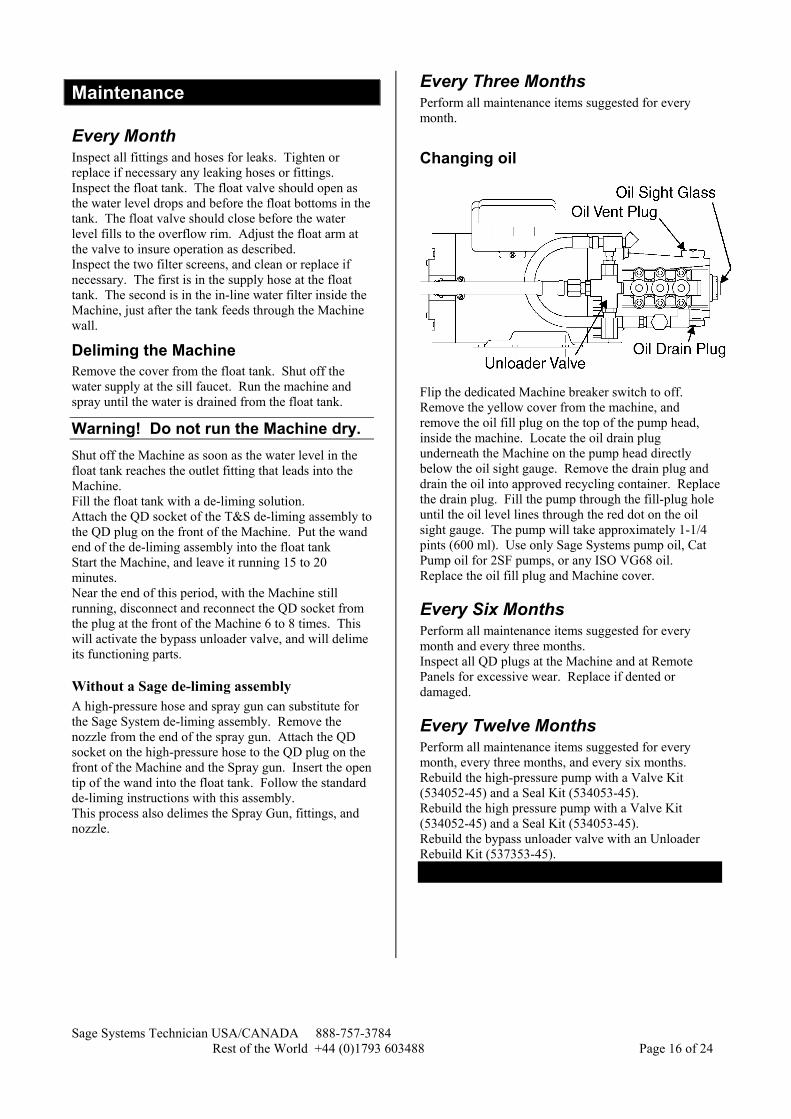
Flip the dedicated Machine breaker switch to off. Remove the yellow cover from the machine, and remove the oil fill plug on the top of the pump head, inside the machine. Locate the oil drain plug underneath the Machine on the pump head directly below the oil sight gauge. Remove the drain plug and drain the oil into approved recycling container. Replace the drain plug. Fill the pump through the fill-plug hole until the oil level lines through the red dot on the oil sight gauge. The pump will take approximately 1-1/4 pints (600 ml). Use only Sage Systems pump oil, Cat Pump oil for 2SF pumps, or any ISO VG68 oil. Replace the oil fill plug and Machine cover.
Every Six Months Perform all maintenance items suggested for every month and every three months. Inspect all QD plugs at the Machine and at Remote Panels for excessive wear. Replace if dented or damaged.
Every Twelve Months Perform all maintenance items suggested for every month, every three months, and every six months. Rebuild the high-pressure pump with a Valve Kit (534052-45) and a Seal Kit (534053-45). Rebuild the high pressure pump with a Valve Kit (534052-45) and a Seal Kit (534053-45). Rebuild the bypass unloader valve with an Unloader Rebuild Kit (537353-45).
Sage Systems Technician USA/CANADA 888-757-3784 Rest of the World +44 (0)1793 603488 Page 17 of 24
Service
Dedicated Sage Technician Sage Systems has established a dedicated Sage Service Technician. Our Technician verifies warranty claims, offers technical support, and connects users with Sage Systems authorized service agencies in their area.
Authorized Service Agents Sage Systems has gathered a full network of CFESA or NAFEM service agencies across the country. These professionals are experienced food equipment repair personnel. They inspect every new remote system installation at Start-up, and can offer regular maintenance or service on demand. To obtain a list of Sage Systems authorized service agents in your area, call our dedicated Sage Technician at (888) 757-3784.
Helpful Service Tips A complete understanding of the interrelation of all the components of a Sage System is essential before any adjustments or repairs are attempted. Please make sure to read the entire manual before proceeding with service issues. The Troubleshooting section includes many helpful tips and suggestions to overcome common problems with Sage machines. Make sure to check this section for some ideas that may not be repeated in this Service section.
High Pressure Pump(s) The high-pressure pump is a positive displacement, direct drive design. The pump is mounted to the front of the motor with four bolts for easy maintenance. The pump rotations per minute (rpm) must be maintained at the fixed design rate in order to produce the optimal flow rate without variation. Typically, all T&S Sage machines are set to output between 2.75 and 2.95 gallons per minute, gpm (10.4 and 11.2 liters per minute, lpm) The pump is supplied fresh water from the float tank at the rear of the machine. The tank cover removes for inspection of the valve inside. The float valve is adjustable, and should be set so that the highest water level is 1 in (2.5 cm) below the over level of the tank. The 1 in (2.5 cm) gap between the tank and cover serve as a back-siphon and back-pressure prevention device. The pump draws water from the float tank with suction. Water is pulled through an in-line water filter, down the pump inlet hose, and to the water inlet manifold of the pump. The inline water filter should be opened and the screen cleaned every month to prevent water starvation of the pump.
Bypass Unloader Valve
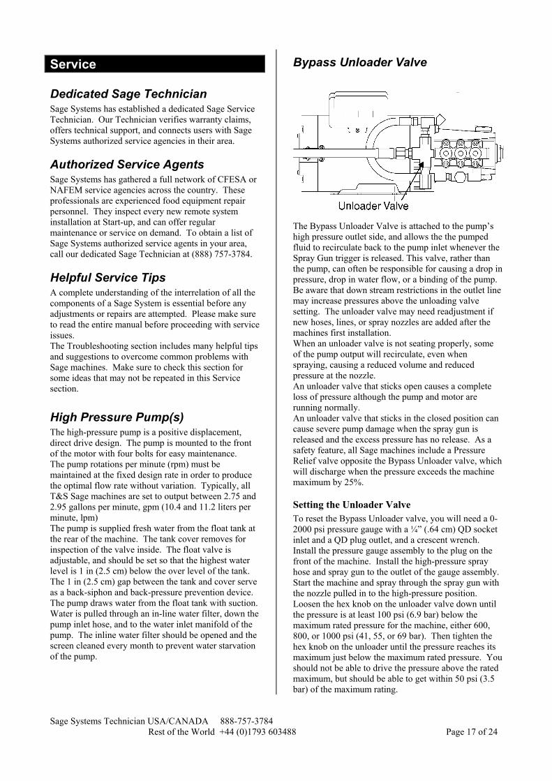
The Bypass Unloader Valve is attached to the pump’s high pressure outlet side, and allows the the pumped fluid to recirculate back to the pump inlet whenever the Spray Gun trigger is released. This valve, rather than the pump, can often be responsible for causing a drop in pressure, drop in water flow, or a binding of the pump. Be aware that down stream restrictions in the outlet line may increase pressures above the unloading valve setting. The unloader valve may need readjustment if new hoses, lines, or spray nozzles are added after the machines first installation. When an unloader valve is not seating properly, some of the pump output will recirculate, even when spraying, causing a reduced volume and reduced pressure at the nozzle. An unloader valve that sticks open causes a complete loss of pressure although the pump and motor are running normally. An unloader valve that sticks in the closed position can cause severe pump damage when the spray gun is released and the excess pressure has no release. As a safety feature, all Sage machines include a Pressure Relief valve opposite the Bypass Unloader valve, which will discharge when the pressure exceeds the machine maximum by 25%.
Setting the Unloader Valve To reset the Bypass Unloader valve, you will need a 0-2000 psi pressure gauge with a ¼” (.64 cm) QD socket inlet and a QD plug outlet, and a crescent wrench. Install the pressure gauge assembly to the plug on the front of the machine. Install the high-pressure spray hose and spray gun to the outlet of the gauge assembly. Start the machine and spray through the spray gun with the nozzle pulled in to the high-pressure position. Loosen the hex knob on the unloader valve down until the pressure is at least 100 psi (6.9 bar) below the maximum rated pressure for the machine, either 600, 800, or 1000 psi (41, 55, or 69 bar). Then tighten the hex knob on the unloader until the pressure reaches its maximum just below the maximum rated pressure. You should not be able to drive the pressure above the rated maximum, but should be able to get within 50 psi (3.5 bar) of the maximum rating.
Sage Systems Technician USA/CANADA 888-757-3784 Rest of the World +44 (0)1793 603488 Page 18 of 24
The normal bypass pressure is within 200 psi (1.4 bar) of the unloader setting. In other words, the unloader valve will open and allow the water to bypass into recirculating mode when the spray gun is released, and the pressure goes up at least 200 psi (1.4 bar) beyond the set pressure.
Note! It is essential that the correct nozzle for the machine be installed to all spray guns on the system. A different orifice size can greatly affect flow rate, maximum pressure, and even amperage. Each nozzle is specified for each machine to optimize flow rate at the specified pressure, while minimizing amperage. Using a different nozzle than is originally specified may cause sever machine damage, and will void warranty.
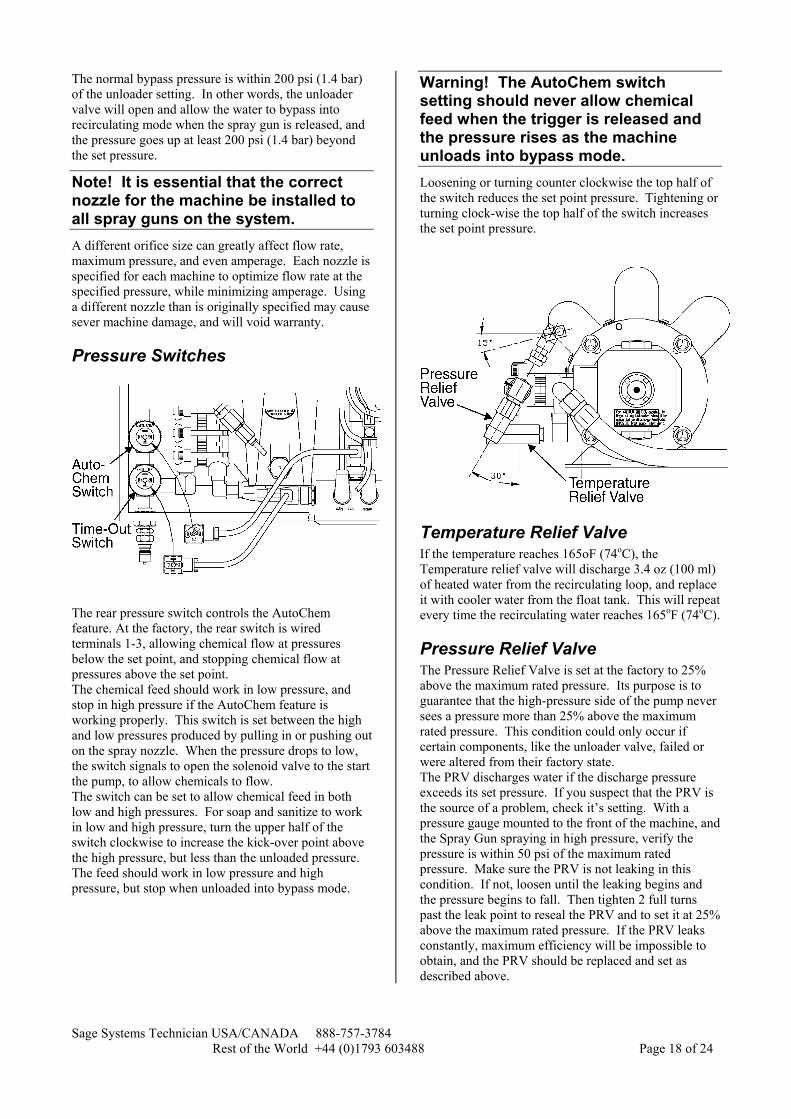
Pressure Switches
The rear pressure switch controls the AutoChem feature. At the factory, the rear switch is wired terminals 1-3, allowing chemical flow at pressures below the set point, and stopping chemical flow at pressures above the set point. The chemical feed should work in low pressure, and stop in high pressure if the AutoChem feature is working properly. This switch is set between the high and low pressures produced by pulling in or pushing out on the spray nozzle. When the pressure drops to low, the switch signals to open the solenoid valve to the start the pump, to allow chemicals to flow. The switch can be set to allow chemical feed in both low and high pressures. For soap and sanitize to work in low and high pressure, turn the upper half of the switch clockwise to increase the kick-over point above the high pressure, but less than the unloaded pressure. The feed should work in low pressure and high pressure, but stop when unloaded into bypass mode.
Warning! The AutoChem switch setting should never allow chemical feed when the trigger is released and the pressure rises as the machine unloads into bypass mode. Loosening or turning counter clockwise the top half of the switch reduces the set point pressure. Tightening or turning clock-wise the top half of the switch increases the set point pressure.
Temperature Relief Valve If the temperature reaches 165oF (74oC), the Temperature relief valve will discharge 3.4 oz (100 ml) of heated water from the recirculating loop, and replace it with cooler water from the float tank. This will repeat every time the recirculating water reaches 165oF (74oC).
Pressure Relief Valve The Pressure Relief Valve is set at the factory to 25% above the maximum rated pressure. Its purpose is to guarantee that the high-pressure side of the pump never sees a pressure more than 25% above the maximum rated pressure. This condition could only occur if certain components, like the unloader valve, failed or were altered from their factory state. The PRV discharges water if the discharge pressure exceeds its set pressure. If you suspect that the PRV is the source of a problem, check it’s setting. With a pressure gauge mounted to the front of the machine, and the Spray Gun spraying in high pressure, verify the pressure is within 50 psi of the maximum rated pressure. Make sure the PRV is not leaking in this condition. If not, loosen until the leaking begins and the pressure begins to fall. Then tighten 2 full turns past the leak point to reseal the PRV and to set it at 25% above the maximum rated pressure. If the PRV leaks constantly, maximum efficiency will be impossible to obtain, and the PRV should be replaced and set as described above.
Sage Systems Technician USA/CANADA 888-757-3784 Rest of the World +44 (0)1793 603488 Page 19 of 24
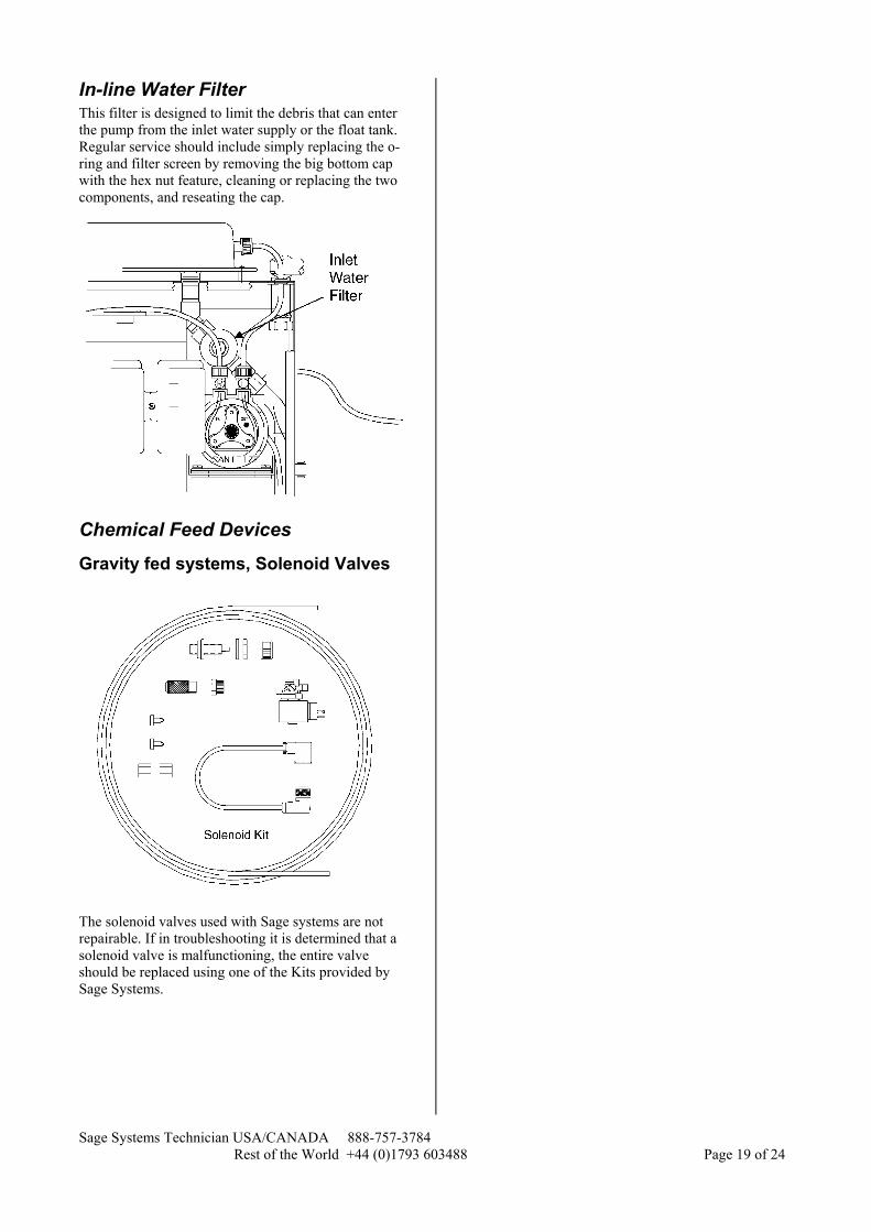
In-line Water Filter This filter is designed to limit the debris that can enter the pump from the inlet water supply or the float tank. Regular service should include simply replacing the o-ring and filter screen by removing the big bottom cap with the hex nut feature, cleaning or replacing the two components, and reseating the cap.
Chemical Feed Devices
Gravity fed systems, Solenoid Valves
The solenoid valves used with Sage systems are not repairable. If in troubleshooting it is determined that a solenoid valve is malfunctioning, the entire valve should be replaced using one of the Kits provided by Sage Systems.

Sage Systems Technician USA/CANADA 888-757-3784 Rest of the World +44 (0)1793 603488 Page 20 of 24
Pump fed systems, Peristaltic pumps
The peristaltic pump(s) pull chemical from their containers with a tripod arrangement of rollers compressing surgical tubing and rolling along the tubing. This creates a suction, and forces chemical into the water lines that feeds the pump. There are two typical Peristaltic pump repair operations. First, you may need to replace the inner tubing. Or, you may need to replace the entire pump.
Replacing the Tubing
First, turn the speed control to OFF. Unscrew the nuts attaching the polytubing to the pump, and pull the polytubing from the white fittings. Pull off the red retaining knob from the motor shaft, and remove the clear cover. Lift out the tubing and fitting assembly. Be careful not to come in contact with any non-diluted chemicals in the tubing or pump assembly. You may turn the pump rollers by hand to assist with removing the tube. Wipe clean the pump head area, and if necessary, clean with a mild soap solution, and rinse with clean water. Lubricate the shaft and rollers with one of the two approved lubricants, either Union Carbide L-45 Dimethyloplysioxane or GE SF96-100 silicone fluid.
Note! The replacement tube is not symmetrical. Position the rollers so that there is space between the first roller and the right side wall. Hold one end of the replacement tubing with fittings in your right hand, with the BW on the fitting facing you. The other end should turn down and to the left. If not, you are holding the wrong end. This twist is essential to allow for the difference of inside and outside length when the tube is threaded into the pump.
Replacing the Tubing
Sage Systems Technician USA/CANADA 888-757-3784 Rest of the World +44 (0)1793 603488 Page 21 of 24
Hold the right fitting in the right hand, and left in the left, in a loop with thumbs on the BW letters. The looped tube should bend away from you. To thread in the tube, insert the right side fitting firmly and all the way into the right lock socket. Feed the tubing between one roller at a time, turning the rollers as necessary to help feed the tubing between the roller and the wall. Keep the BW in the left hand facing up, without twisting the tubing to do so. Use the right thumb to assist with pressing the tubing down between the roller and the wall.
Caution! Be careful to avoid pinching fingers in he turning rollers. After the tubing is in place at all three rollers, press the left fitting into its place. Replace the cover and retating knob. Cut about 0.25 in (0.2 cm) from the end of the inlet and outlet polytubing, making sure to keep the nut up the tubing while cutting. Press the freshly cut inlet and outlet tubing onto the pump fittings, and tighten the nuts over the connections. Reset the control knob to its previous position for the same feed rate as before.
Replacing the Pump Turn the Machine and Master Power off at the MCP. Disconnect the inlet and outlet polytubing. Disconnect the yellow electrical fitting from the wiring box in the machine. Unscrew the two screws that hold the pump to the welded vertical bracket inside the machine. Remove the pump. Insert the new pump, and attach to the bracket with the two screws. Attach the ¼ turn electrical connector of the new pump to the same port where the previous plug was attached. Cut about 0.25 in (0.2 cm) from the end of the inlet and outlet polytubing, making sure to keep the nut up the tubing while cutting. Press the freshly cut inlet and outlet tubing onto the pump fittings, and tighten the nuts over the connections.
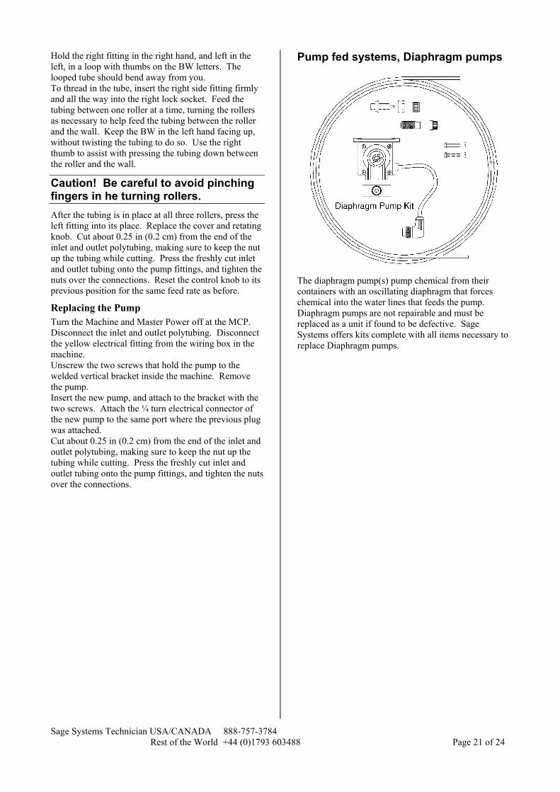
Pump fed systems, Diaphragm pumps
The diaphragm pump(s) pump chemical from their containers with an oscillating diaphragm that forces chemical into the water lines that feeds the pump. Diaphragm pumps are not repairable and must be replaced as a unit if found to be defective. Sage Systems offers kits complete with all items necessary to replace Diaphragm pumps.

Sage Systems Technician USA/CANADA 888-757-3784 Rest of the World +44 (0)1793 603488 Page 22 of 24

Sage Systems Technician USA/CANADA 888-757-3784 Rest of the World +44 (0)1793 603488 Page 23 of 24