Embed Size (px)
Citation preview
Control Theory and Informatics www.iiste.org
ISSN 2224-5774 (Paper) ISSN 2225-0492 (Online)
Vol.3, No.4, 2013
27
Mobile Robotic Platform to Gathering Real Time Sensory Data in
Wireless Personal Area Network using Zigbee Transceiver
Module
Rajesh Singh
HEAD, Robotics Institute R&D, Assistant Professor,
University of petroleum and Energy studies, Dehradun, INDIA
Vivek Kaundal
College of Engineering Studies, Assistant Professor,
University of petroleum and Energy studies, Dehradun, INDIA
Purnendu S Pandey, Lecturer,
THDC institute of hydropower Engg. & Technology, INDIA
Shashank Mishra
Student EE branch 3rd
year
University of petroleum and Energy studies, Dehradun, INDIA
Abstract
Robots are intelligent and obedient but impersonal machine which perform functions according to their own
intelligence. Now days monitoring and control plays very vital role in every sectors .we can able to provide
wirelessly controlled robots using Wireless personal Area Network (WPAN) interface with the help of Graphical
User Interface (GUI) of MATLAB, which are capable of detecting the gas contents and temperature and send it
back to the control room. Now the data which is now available in the receiving end determines the further action
of robots. The whole process is cost effective and economically sound. Further these wireless robots have broad
applications like in wireless home security applications, coal mining, spy and war robots as they can make
through in enemy areas just to track their activities. Other applications like in Nuclear Power Plant we can send
them in Radioactive area toanalyze things which is normally not possible for humans.
Keywords:Wpan, Zigbbe, Matlab Gui
1. Introduction
In this Paper we are focus on wireless robots which are working in oil and gas industries .The WPAN comprises
of semi autonomous devices using sensors to effectively monitor physical or environmental parameters which
play an important role in oil and gas industries in process monitoring, controlling . These may include various
parameters such as temperature in highly flammable areas , gas concentration , oil leakage in pipe lines. Here we
are more concern about application of such wireless robots using GUI with the help of MATLAB. We prefer
GUI over other terminals (like Hyper Terminal, V1.9B Terminal and AVR Terminal etc.) because:
• GUI is user friendly interface as it allows user to interact with electronic devices with the help of
images rather than text commands.
• As we are using it with MATLAB GUI , we can plot the performance plot of (say temperature,
concentration of several of gases and detecting errors in different sectors etc.
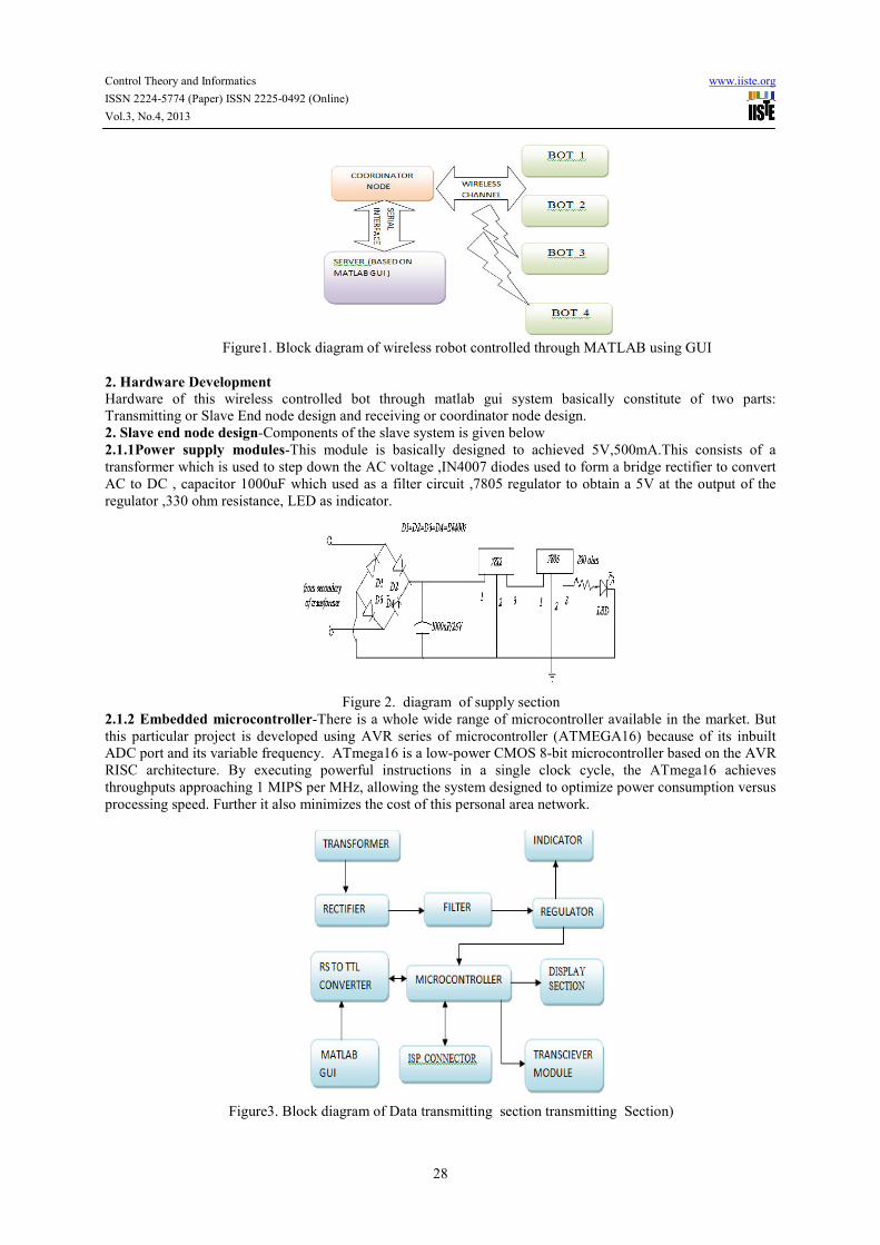
The above fig(1.0) represents the block diagram of wireless robot controlled through MATLAB using GUI .
Here coordinator node has to receive the data which is transmitted by the different BOT’s .then data is
transferred to the PC using serial interface to the GUI . If the readings are above a certain value then the BOT’s
are manage to perform desired operation.
Control Theory and Informatics www.iiste.org
ISSN 2224-5774 (Paper) ISSN 2225-0492 (Online)
Vol.3, No.4, 2013
28
Figure1. Block diagram of wireless robot controlled through MATLAB using GUI
2. Hardware Development Hardware of this wireless controlled bot through matlab gui system basically constitute of two parts:
Transmitting or Slave End node design and receiving or coordinator node design.
2. Slave end node design-Components of the slave system is given below
2.1.1Power supply modules-This module is basically designed to achieved 5V,500mA.This consists of a
transformer which is used to step down the AC voltage ,IN4007 diodes used to form a bridge rectifier to convert
AC to DC , capacitor 1000uF which used as a filter circuit ,7805 regulator to obtain a 5V at the output of the
regulator ,330 ohm resistance, LED as indicator.
Figure 2. diagram of supply section
2.1.2 Embedded microcontroller-There is a whole wide range of microcontroller available in the market. But
this particular project is developed using AVR series of microcontroller (ATMEGA16) because of its inbuilt
ADC port and its variable frequency. ATmega16 is a low-power CMOS 8-bit microcontroller based on the AVR
RISC architecture. By executing powerful instructions in a single clock cycle, the ATmega16 achieves
throughputs approaching 1 MIPS per MHz, allowing the system designed to optimize power consumption versus
processing speed. Further it also minimizes the cost of this personal area network.
Figure3. Block diagram of Data transmitting section transmitting Section)
Control Theory and Informatics www.iiste.org
ISSN 2224-5774 (Paper) ISSN 2225-0492 (Online)
Vol.3, No.4, 2013
29
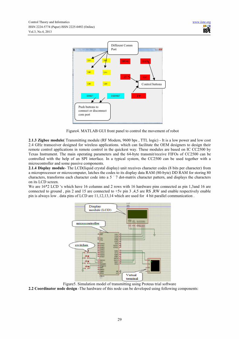
Figure4. MATLAB GUI front panel to control the movement of robot
2.1.3 Zigbee module( Transmitting module (RF Modem, 9600 bps , TTL logic) - It is a low power and low cost
2.4 GHz transceiver designed for wireless applications. which can facilitate the OEM designers to design their
remote control applications in remote control in the quickest way. These modules are based on IC CC2500 by
Texas Instrument. The main operating parameters and the 64-byte transmit/receive FIFOs of CC2500 can be
controlled with the help of an SPI interface. In a typical system, the CC2500 can be used together with a
microcontroller and some passive components.
2.1.4 Display module- The LCD(liquid crystal display) unit receives character codes (8 bits per character) from
a microprocessor or microcomputer, latches the codes to its display data RAM (80-byte) DD RAM for storing 80
characters, transforms each character code into a 5 ´ 7 dot-matrix character pattern, and displays the characters
on its LCD screen.
We are 16*2 LCD ‘s which have 16 columns and 2 rows with 16 hardware pins connected as pin 1,3and 16 are
connected to ground , pin 2 and 15 are connected to +5v pin 3 ,4,5 are RS ,RW and enable respectively enable
pin is always low . data pins of LCD are 11,12,13,14 which are used for 4 bit parallel communication .
Figure5. Simulation model of transmitting using Proteus trial software
2.2 Coordinator node design -The hardware of this node can be developed using following components:
Push buttons to
connect or disconnect
com port
Control buttons
Different Comm
Port
Control Theory and Informatics www.iiste.org
ISSN 2224-5774 (Paper) ISSN 2225-0492 (Online)
Vol.3, No.4, 2013
30
Figure6. Block diagram of parametering monitoring section (Receiving Section)
2.2.1 Power supply unit-It is same as describe described above.
2.2.2 Zigbee module-Same as receiving module used in Node1 to Node 5 design.
2.2.3 MAX 232(level converter)-MAX232 is a dual driver/receiver IC that includes a capacitive voltage
generator to supply EIA-232 voltage levels from a single 5-V supply [2]. Each receiver converts EIA-232
inputs to 5-V TTL/CMOS levels. These receivers have a typical threshold of 1.3 V and a typical hysteresis
of 0.5 V, and can accept ±30-V inputs. Each driver converts TTL/CMOS input levels into EIA-232 levels.
This can be made to work with the help of a few capacitors attached to it.
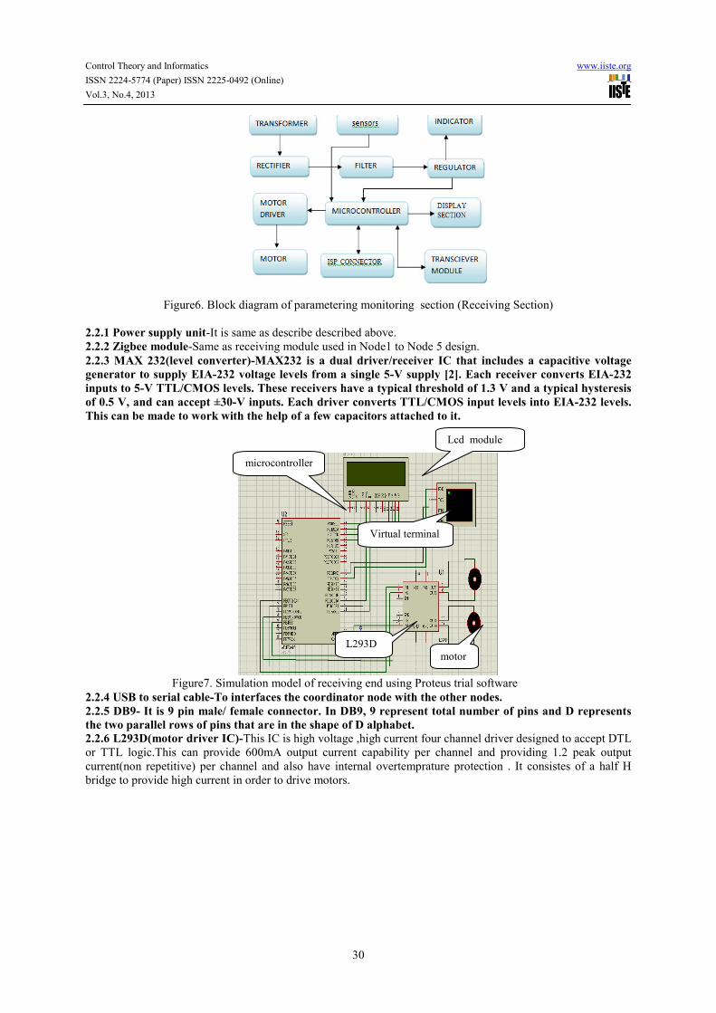
Figure7. Simulation model of receiving end using Proteus trial software
2.2.4 USB to serial cable-To interfaces the coordinator node with the other nodes.
2.2.5 DB9- It is 9 pin male/ female connector. In DB9, 9 represent total number of pins and D represents
the two parallel rows of pins that are in the shape of D alphabet.
2.2.6 L293D(motor driver IC)-This IC is high voltage ,high current four channel driver designed to accept DTL
or TTL logic.This can provide 600mA output current capability per channel and providing 1.2 peak output
current(non repetitive) per channel and also have internal overtemprature protection . It consistes of a half H
bridge to provide high current in order to drive motors.
Lcd module
microcontroller
L293D
Virtual terminal
motor
Control Theory and Informatics www.iiste.org
ISSN 2224-5774 (Paper) ISSN 2225-0492 (Online)
Vol.3, No.4, 2013
31
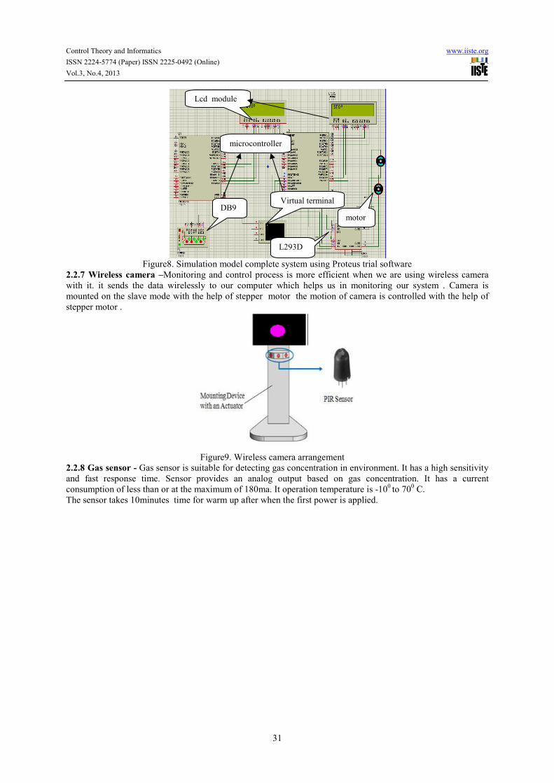
Figure8. Simulation model complete system using Proteus trial software
2.2.7 Wireless camera –Monitoring and control process is more efficient when we are using wireless camera
with it. it sends the data wirelessly to our computer which helps us in monitoring our system . Camera is
mounted on the slave mode with the help of stepper motor the motion of camera is controlled with the help of
stepper motor .
Figure9. Wireless camera arrangement
2.2.8 Gas sensor - Gas sensor is suitable for detecting gas concentration in environment. It has a high sensitivity
and fast response time. Sensor provides an analog output based on gas concentration. It has a current
consumption of less than or at the maximum of 180ma. It operation temperature is -100 to 70
0 C.
The sensor takes 10minutes time for warm up after when the first power is applied.
Lcd module
microcontroller
Virtual terminal
L293D
motor
DB9
Control Theory and Informatics www.iiste.org
ISSN 2224-5774 (Paper) ISSN 2225-0492 (Online)
Vol.3, No.4, 2013
32
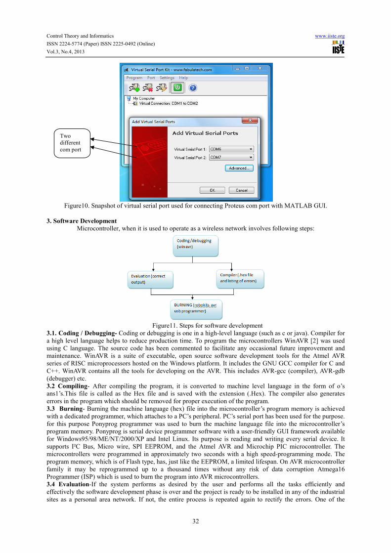
Figure10. Snapshot of virtual serial port used for connecting Proteus com port with MATLAB GUI.
3. Software Development
Microcontroller, when it is used to operate as a wireless network involves following steps:
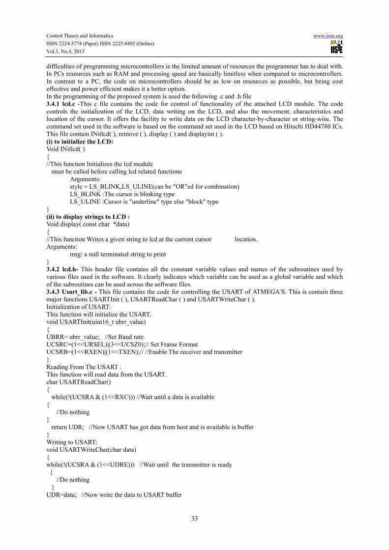
Figure11. Steps for software development
3.1. Coding / Debugging- Coding or debugging is one in a high-level language (such as c or java). Compiler for
a high level language helps to reduce production time. To program the microcontrollers WinAVR [2] was used
using C language. The source code has been commented to facilitate any occasional future improvement and
maintenance. WinAVR is a suite of executable, open source software development tools for the Atmel AVR
series of RISC microprocessors hosted on the Windows platform. It includes the GNU GCC compiler for C and
C++. WinAVR contains all the tools for developing on the AVR. This includes AVR-gcc (compiler), AVR-gdb
(debugger) etc.
3.2 Compiling- After compiling the program, it is converted to machine level language in the form of o’s
ans1’s.This file is called as the Hex file and is saved with the extension (.Hex). The compiler also generates
errors in the program which should be removed for proper execution of the program.
3.3 Burning- Burning the machine language (hex) file into the microcontroller’s program memory is achieved
with a dedicated programmer, which attaches to a PC’s peripheral. PC’s serial port has been used for the purpose.
for this purpose Ponyprog programmer was used to burn the machine language file into the microcontroller’s
program memory. Ponyprog is serial device programmer software with a user-friendly GUI framework available
for Windows95/98/ME/NT/2000/XP and Intel Linux. Its purpose is reading and writing every serial device. It
supports I²C Bus, Micro wire, SPI EEPROM, and the Atmel AVR and Microchip PIC microcontroller. The
microcontrollers were programmed in approximately two seconds with a high speed-programming mode. The
program memory, which is of Flash type, has, just like the EEPROM, a limited lifespan. On AVR microcontroller
family it may be reprogrammed up to a thousand times without any risk of data corruption Atmega16
Programmer (ISP) which is used to burn the program into AVR microcontrollers.
3.4 Evaluation-If the system performs as desired by the user and performs all the tasks efficiently and
effectively the software development phase is over and the project is ready to be installed in any of the industrial
sites as a personal area network. If not, the entire process is repeated again to rectify the errors. One of the
Two
different
com port
Control Theory and Informatics www.iiste.org
ISSN 2224-5774 (Paper) ISSN 2225-0492 (Online)
Vol.3, No.4, 2013
33
difficulties of programming microcontrollers is the limited amount of resources the programmer has to deal with.
In PCs resources such as RAM and processing speed are basically limitless when compared to microcontrollers.
In contrast to a PC, the code on microcontrollers should be as low on resources as possible, but being cost
effective and power efficient makes it a better option.
In the programming of the proposed system is used the following .c and .h file
3.4.1 lcd.c -This c file contains the code for control of functionality of the attached LCD module. The code
controls the initialization of the LCD, data writing on the LCD, and also the movement, characteristics and
location of the cursor. It offers the facility to write data on the LCD character-by-character or string-wise. The
command set used in the software is based on the command set used in the LCD based on Hitachi HD44780 ICs.
This file contain INitlcd( ), remove ( ), display ( ) and displayint ( ).
(i) to initialize the LCD:
Void INitlcd( )
{
//This function Initializes the lcd module
must be called before calling lcd related functions
Arguments:
style = LS_BLINK,LS_ULINE(can be "OR"ed for combination)
LS_BLINK :The cursor is blinking type
LS_ULINE :Cursor is "underline" type else "block" type
}
(ii) to display strings to LCD : Void display( const char *data)
{
//This function Writes a given string to lcd at the current cursor location.
Arguments:
msg: a null terminated string to print
}
3.4.2 lcd.h- This header file contains all the constant variable values and names of the subroutines used by
various files used in the software. It clearly indicates which variable can be used as a global variable and which
of the subroutines can be used across the software files.
3.4.3 Usart_lib.c - This file contains the code for controlling the USART of ATMEGA’S. This is contain three
major functions USARTInit ( ), USARTReadChar ( ) and USARTWriteChar ( ).
Initialization of USART:
This function will initialize the USART.
void USARTInit(uint16_t ubrr_value)
{
UBRR= ubrr_value; //Set Baud rate
UCSRC=(1<<URSEL)|(3<<UCSZ0);// Set Frame Format
UCSRB=(1<<RXEN)|(1<<TXEN);// //Enable The receiver and transmitter
}
Reading From The USART :
This function will read data from the USART.
char USARTReadChar()
{
while(!(UCSRA & (1<<RXC))) //Wait until a data is available
{
//Do nothing
}
return UDR; //Now USART has got data from host and is available is buffer
}
Writing to USART:
void USARTWriteChar(char data)
{
while(!(UCSRA & (1<<UDRE))) //Wait until the transmitter is ready
{
//Do nothing
}
UDR=data; //Now write the data to USART buffer
Control Theory and Informatics www.iiste.org
ISSN 2224-5774 (Paper) ISSN 2225-0492 (Online)
Vol.3, No.4, 2013
34
}
3.4.4 Adc.c- This file contains the code for controlling the ADC of ATMEGA’S. This is contain two major
functions initializeADC( ), int ReadADC(uint8_t ch). This helps us to read various sensors .
(i)-Initialization of ADC:
Initialize ADC()
{
ADMUX=(1<<REFS0);// For Aref=AVcc;
ADCSRA=(1<<ADEN)|(7<<ADPS0);
}
(ii) Read data from ADC:
Int ReadADC(uint8_t ch)
{
//Select ADC Channel ch must be 0-7
//Start Single conversion
//Wait for conversion to complete
//Clear ADIF by writing one to it
return(ADC);
}
3.4.5 functions used in program : The code which is used to program the controller include some functions
as :
to provide delay in the program
Void delay (unsigned char value)
{
For(unsigned int i=0;i<value;i++)
{
_delay_ms(1);
}
}
controlling of the motor
Void motor(char data)
{
Switch(data)
{
Case ‘a’: motor forward;
Break;
Case ‘b’: motor reverse;
Break;
Case ‘c’: motor left;
Break;
Case ‘d’: motor right;
Break;
Default: motor stop;
Break;
}
}
Control Theory and Informatics www.iiste.org
ISSN 2224-5774 (Paper) ISSN 2225-0492 (Online)
Vol.3, No.4, 2013
35
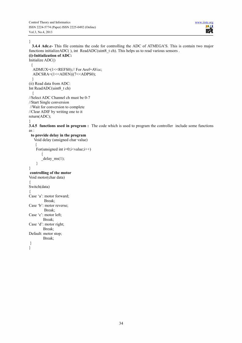
Fig (3.1): snapshot C coding for proposed system using of AVRstudio4
Figure12. view of hardware AVR programmer (ISP) by Robokits
Figure13.snapshot of robokits AVR programmer window to erase, write and verify .h file generated by
AVRstudio4 to target
3.4.6 Development of GUI using MATLAB :
To develop a GUI in MATLAB open the matlab and open new GUI file(.fig) and select the buttons and place
them in the .fig file after running this window a window will open in which code for the working of GUI is
written . After writing code for every buttons that you were placed in .fig file run that window after this a new
window will open which contains the GUI through which we can use our hardware and control it .
Control Theory and Informatics www.iiste.org
ISSN 2224-5774 (Paper) ISSN 2225-0492 (Online)
Vol.3, No.4, 2013
36
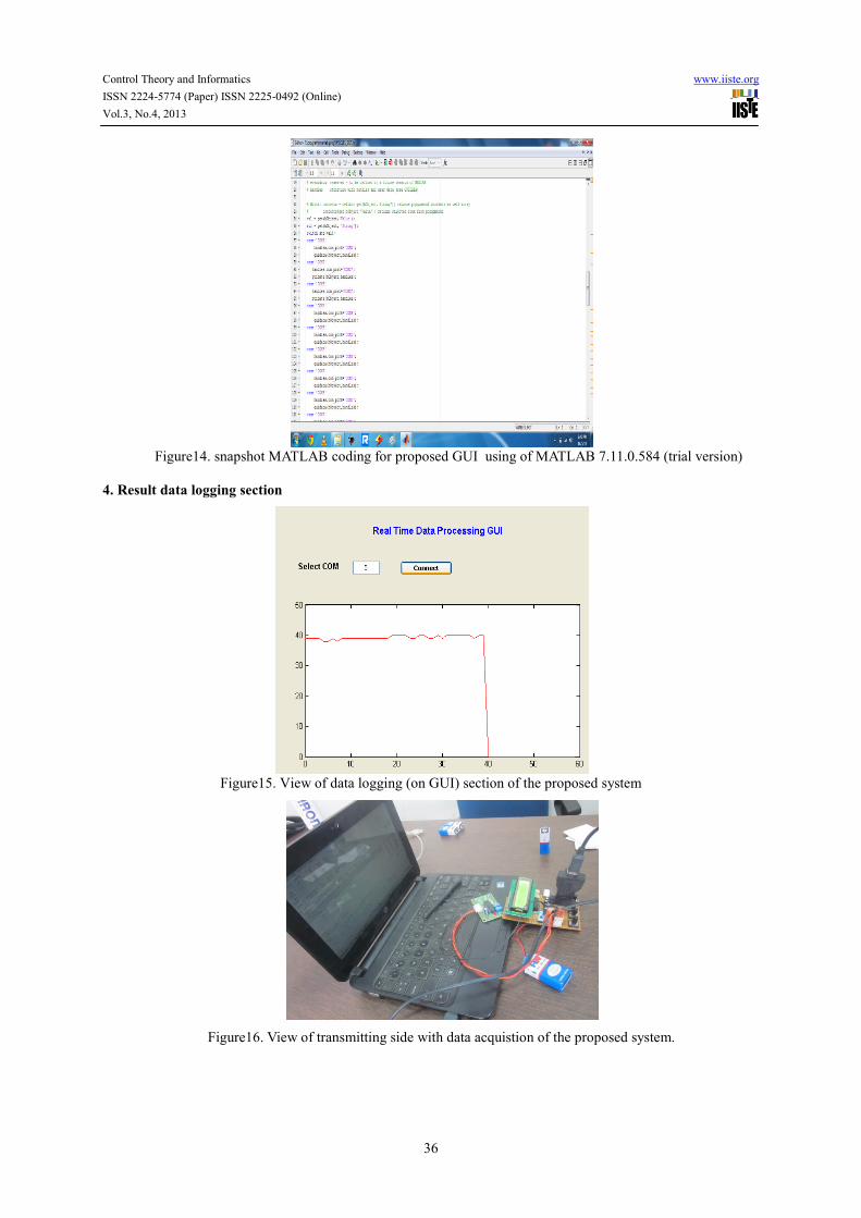
Figure14. snapshot MATLAB coding for proposed GUI using of MATLAB 7.11.0.584 (trial version)
4. Result data logging section
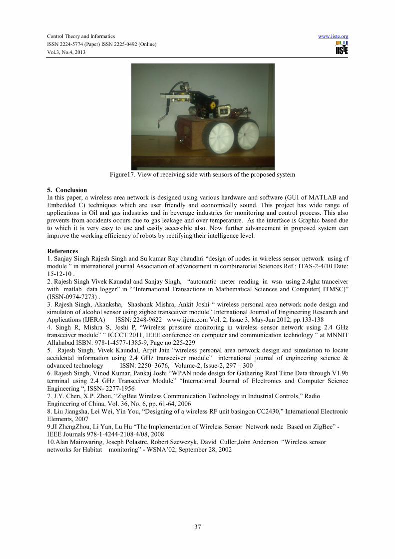
Figure15. View of data logging (on GUI) section of the proposed system
Figure16. View of transmitting side with data acquistion of the proposed system.
Control Theory and Informatics www.iiste.org
ISSN 2224-5774 (Paper) ISSN 2225-0492 (Online)
Vol.3, No.4, 2013
37
Figure17. View of receiving side with sensors of the proposed system
5. Conclusion In this paper, a wireless area network is designed using various hardware and software (GUI of MATLAB and
Embedded C) techniques which are user friendly and economically sound. This project has wide range of
applications in Oil and gas industries and in beverage industries for monitoring and control process. This also
prevents from accidents occurs due to gas leakage and over temperature. As the interface is Graphic based due
to which it is very easy to use and easily accessible also. Now further advancement in proposed system can
improve the working efficiency of robots by rectifying their intelligence level.
References
1. Sanjay Singh Rajesh Singh and Su kumar Ray chaudhri “design of nodes in wireless sensor network using rf
module ” in international journal Association of advancement in combinatorial Sciences Ref.: ITAS-2-4/10 Date:
15-12-10 .
2. Rajesh Singh Vivek Kaundal and Sanjay Singh, “automatic meter reading in wsn using 2.4ghz tranceiver
with matlab data logger” in ““International Transactions in Mathematical Sciences and Computer( ITMSC)”
(ISSN-0974-7273) .
3. Rajesh Singh, Akanksha, Shashank Mishra, Ankit Joshi “ wireless personal area network node design and
simulaton of alcohol sensor using zigbee transceiver module” International Journal of Engineering Research and
Applications (IJERA) ISSN: 2248-9622 www.ijera.com Vol. 2, Issue 3, May-Jun 2012, pp.133-138
4. Singh R, Mishra S, Joshi P, “Wireless pressure monitoring in wireless sensor network using 2.4 GHz
transceiver module” “ ICCCT 2011, IEEE conference on computer and communication technology “ at MNNIT
Allahabad ISBN: 978-1-4577-1385-9, Page no 225-229
5. Rajesh Singh, Vivek Kaundal, Arpit Jain “wireless personal area network design and simulation to locate
accidental information using 2.4 GHz transceiver module” international journal of engineering science &
advanced technology ISSN: 2250–3676, Volume-2, Issue-2, 297 – 300
6. Rajesh Singh, Vinod Kumar, Pankaj Joshi “WPAN node design for Gathering Real Time Data through V1.9b
terminal using 2.4 GHz Transceiver Module” “International Journal of Electronics and Computer Science
Engineering “, ISSN- 2277-1956
7. J.Y. Chen, X.P. Zhou, “ZigBee Wireless Communication Technology in Industrial Controls,” Radio
Engineering of China, Vol. 36, No. 6, pp. 61-64, 2006
8. Liu Jiangsha, Lei Wei, Yin You, “Designing of a wireless RF unit basingon CC2430,” International Electronic
Elements, 2007
9.JI ZhengZhou, Li Yan, Lu Hu “The Implementation of Wireless Sensor Network node Based on ZigBee” -
IEEE Journals 978-1-4244-2108-4/08, 2008
10.Alan Mainwaring, Joseph Polastre, Robert Szewczyk, David Culler,John Anderson “Wireless sensor
networks for Habitat monitoring” - WSNA’02, September 28, 2002

This academic article was published by The International Institute for Science,
Technology and Education (IISTE). The IISTE is a pioneer in the Open Access
Publishing service based in the U.S. and Europe. The aim of the institute is
Accelerating Global Knowledge Sharing.
More information about the publisher can be found in the IISTE’s homepage:
http://www.iiste.org
CALL FOR JOURNAL PAPERS
The IISTE is currently hosting more than 30 peer-reviewed academic journals and
collaborating with academic institutions around the world. There’s no deadline for
submission. Prospective authors of IISTE journals can find the submission
instruction on the following page: http://www.iiste.org/journals/ The IISTE
editorial team promises to the review and publish all the qualified submissions in a
fast manner. All the journals articles are available online to the readers all over the
world without financial, legal, or technical barriers other than those inseparable from
gaining access to the internet itself. Printed version of the journals is also available
upon request of readers and authors.
MORE RESOURCES
Book publication information: http://www.iiste.org/book/
Recent conferences: http://www.iiste.org/conference/
IISTE Knowledge Sharing Partners
EBSCO, Index Copernicus, Ulrich's Periodicals Directory, JournalTOCS, PKP Open
Archives Harvester, Bielefeld Academic Search Engine, Elektronische
Zeitschriftenbibliothek EZB, Open J-Gate, OCLC WorldCat, Universe Digtial
Library , NewJour, Google Scholar


![Deep Networks with Confidence Bounds for Robotic ...research.engr.oregonstate.edu/rdml/sites/research.engr.oregonstate.… · the card game Magic The Gathering [24]. Monte Carlo](https://img.pdfslide.net/doc/110x75/5f479181cd11e92d07553906/deep-networks-with-conidence-bounds-for-robotic-the-card-game-magic-the-gathering.jpg)