Embed Size (px)
Citation preview

Mobile Rope Load Meter
MSM 12
Operating Instructions

Mobile Rope Measurement MSM 12
Henning GmbH Page 2 3.0 / 11.2010
Copyright © Copyright 2010 by Henning GmbH, Loher Str. 4 + 30, D-58332 Schwelm Warranty
This description has been drawn up by Henning GmbH to the best of their knowl-edge. All technical statements have been carefully established and checked. They correspond to the state of the art. Changes and errors excepted.
Our application engineering advice – spoken and written – shall support your own work. It is regarded as an indication without obligation – also with regard to possible third party industrial property rights – and does not release you from your own obliga-tion to carry out appropriate testing of the products regarding their suitability for the intended application.
Product descriptions do not contain statements about the liability for possible dam-ages. However, should a liability be involved, it would be limited for all damages to the value of the goods supplied and used.
Suggestions and comments are welcomed.
Address
Henning GmbH
Loher Str. 4 + 30 58332 Schwelm
Deutschland
Phone: 02336 / 9 29 8 – 0 FAX: 02336 / 9 29 8 – 10
email: [email protected]
URL : http://www.henning-gmbh.de/
Service-Hotline: 02336 / 9 29 8 - 32
Any kind of duplication, in part or in whole, is only permitted with the written approval of Henning GmbH.
Technical changes excepted!

Mobile Rope Measurement MSM 12
Henning GmbH Page 3 3.0 / 11.2010
CONTENTS
1 Scope of delivery ................................................................................................ 4
2 Power supply ...................................................................................................... 4
3 Control elements ................................................................................................ 5
4 Preparations ....................................................................................................... 5
5 Connecting the MSM12 to the computer ............................................................ 5
6 Rope load sensors LSM ..................................................................................... 6
6.1 Mode of operation .......................................................................................... 6
6.2 Connections ................................................................................................... 6
6.3 Handling ......................................................................................................... 6
7 Operation ........................................................................................................... 9
7.1 Installation of the rope load sensors LSM ...................................................... 9
7.2 Switching-on .................................................................................................. 9
7.3 Main display ................................................................................................... 9
7.4 Menu ............................................................................................................ 11
7.4.1 Save current rope loads ........................................................................... 12
7.4.2 Configuration ........................................................................................... 13
7.4.3 Rope load wizard ..................................................................................... 17
8 Carrying-out of measurements ......................................................................... 19
8.1 Installation position of the sensors in the rope ............................................. 19
8.1.1 General conditions ................................................................................... 19
8.2 Rope adjustment .......................................................................................... 20
8.3 Weight measurement ................................................................................... 22
9 Option: Bluetooth connection ........................................................................... 22
9.1 Installation of the Bluetooth adapter............................................................. 22
9.2 Bluetooth pairing .......................................................................................... 23
10 Technical Data ................................................................................................. 25

Mobile Rope Measurement MSM 12
Henning GmbH Page 4 3.0 / 11.2010
List of figures
Figure 1: Main display .............................................................................................. 10
Figure 2: Menu structure .......................................................................................... 11
Figure 3: Saving of the rope loads ............................................................................ 12
Figure 4: Assignment of the measurement ID .......................................................... 12
Figure 5: Configuration menu ................................................................................... 13
Figure 6: Selection of the language .......................................................................... 13
Figure 7: Selection of the sensor type ...................................................................... 14
Figure 8: Suspension ratio setting ........................................................................... 15
Figure 9: Set date /time ............................................................................................ 15
Figure 10: Delete storage ......................................................................................... 16
Figure 11: Set tolerance ........................................................................................... 16
Figure 12: Display unit setting .................................................................................. 17
Figure 13: Rope load wizard ..................................................................................... 17
Figure 14: Storage of the rope load setting............................................................... 18
1 Scope of delivery 1 x Mobile rope load meter MSM12 1 x External aerial (optional) (Part no.: 45 000 404) 1 x Bluetooth USB adapter class 1 (optional) (including driver and documentation CD) (Part no.: 45 000 403) 1 x USB-A-B cable 1.8 m (Part no.: 450 000 531) 4 x Mobile rope sensor LSM
2 Power supply For the operation of the mobile rope load meter MSM12 you also require 4 alkali-manganese round cells type LR6, AA. These are not included in the scope of delivery. Instead of the LR6 round cells you can also insert NiMH rechargeable batteries with a capacity of minimum 2,000 mAh.

Mobile Rope Measurement MSM 12
Henning GmbH Page 5 3.0 / 11.2010
3 Control elements
Connections for rope load sensors LSM1 Aerial connection (optional) Display with touch screen USB connection On / off switch
4 Preparations Open the battery chamber on the back of the MSM12. Insert the batteries as shown on the illustration opposite. Take care that the batteries have the correct polarity. Improperly inserted batteries may damage the device! If it is intended to store the MSM12 for a long time, the batteries must be removed in order to protect the device. MSM12 with Bluetooth option: Screw the factory-supplied aerial to the aerial connection. The aerial has a link by which it can be moved into a favourable transmission position. Generally it is favour-able to place the aerial in an upright position. For transport and storage the aerial can be unscrewed.
5 Connecting the MSM12 to the computer The free of charge operating software for the MSM12 can be downloaded on our Homepage www.henning-gmbh.de. The drivers for the USB interface are installed together with the software, i. e., when connecting the computer to the MSM12 using an USB-A-B cable the drivers are

Mobile Rope Measurement MSM 12
Henning GmbH Page 6 3.0 / 11.2010
automatically installed by Windows XP. Otherwise, Windows will prompt you to indi-cate the storage location of the drivers. The drivers are found on the program direc-tory.
6 Rope load sensors LSM
Set screw Rope clamps Clamping lever Connection line to the MSM12
6.1 Mode of operation
The rope sensor is based on a patented measuring procedure which, for the first time, permits the carrying out of absolute weight measurements without calibration in the rope. Inside the sensor there is a strain gauge the signals of which are condi-tioned by the integrated electronics and are passed via the USB plug of the sensor to the rope load evaluation unit MSM12. Each rope sensor LSM is individually calibrated.
6.2 Connections
The LSM is provided with a 0.8 m cable for connection to the MSM12. The cable is equipped with a USB-A connector. The sensor has no further connection options.
6.3 Handling
Please, take care that the LSM connector is free of dust, liquids etc. so that the con-tact is not impaired. In order to use the sensor in a rope, please proceed as follows:
1. Bring the clamping lever into the open position and insert the sensor into the rope. If this is not possible, open the set screw by several turns. Now tighten the set screw so far until the marking of the LSM corresponds to the desired rope diameter on the type label.
2. Now close the clamping lever and take care that the rope is still running in the groove of the sensor.

Mobile Rope Measurement MSM 12
Henning GmbH Page 7 3.0 / 11.2010
3. Connect the just installed LSM sensor to the MSM12 rope load evaluation unit with the USB cable.
Step 1
Step 2 Step 3
After installing the sensor you can check the right clamping force with the adjustment indicator. The clamping force is correct, if the edge of the silver cylinder is aligned to the middle of the green o-ring. The width of the green o-ring determines the setting tolerance. If the edge of the cylinder is not aligned to the o-ring, you have to re-adjust the rope diameter.

Mobile Rope Measurement MSM 12
Henning GmbH Page 8 3.0 / 11.2010
The following pictures are showing the adjustment indicator with right and false ad-justed clamps: False adjusted:
Right adjusted:
Mobile Rope Measurement MSM 12
Henning GmbH Page 9 3.0 / 11.2010
7 Operation The handling of the mobile rope load meter MSM12 is described below. For opera-tion of the MSM12 using the optional software refer to the software operating instruc-tions.
7.1 Installation of the rope load sensors LSM
In each LSM rope a rope load sensor must be installed as described in chapter 6. Take care that you assign the connections of the rope sensors at the MSM12 in con-tinuous and ascending order, starting with connection 1. For the use of the rope load wizard it is important that you do not skip any connections.
7.2 Switching-on
In order to switch on the MSM12 mobile rope load meter please press the on/off switch for minimum 3 seconds. The display now shows the Henning logo. After a short time the display switches to the main display. The MSM12 is now ready for op-eration. To switch off please press the on/off switch for minimum 3 seconds again. The de-vice switches off, the display lighting is extinguished. If the inserted batteries are run-down, the MSM12 switches off automatically. The approaching switch-off is indicated 30 seconds in advance by a flashing weight display. In order to avoid a damage of the MSM12 spent batteries should be replaced as soon as possible by new ones. In order to guarantee the data storage of the real-time clock of the MSM12 it should not be left more than 20 minutes without voltage sup-ply. In the switched-off condition the run-down batteries supply the clock with voltage for one week. The loads and adjustment records are stored in non-volatile memory in the MSM12 and are maintained up to ten years without having to insert batteries.
7.3 Main display
Figure 1 shows the main display of the mobile rope load meter MSM12. In the upper two lines of the main display the status bar indicator and the indication of the individ-ual weight of each rope under the corresponding sensor number are displayed. Be-low, in the centre, the total weight resulting from the individual weights is indicated. At the right side and below the total weight three menu buttons SAVE, CONFIG and ADJUST are to be found which will be described in detail below. In the lower left-hand corner the time and date are displayed.

Mobile Rope Measurement MSM 12
Henning GmbH Page 10 3.0 / 11.2010
Figure 1: Main display
Die The individual weight display shows the measured load of each connected rope load sensor. If no sensor is connected to the relevant measuring channel or if the relevant rope load sensor is defective, Err1 is displayed. If the connected rope load sensor is overloaded, Err2 is displayed. The suspension ratio of the elevator can be selected by the user. The displayed total weight is calculated by this factor. The individual weight display hereby remains unaffected. The total weight is the sum of all individual rope loads measured, if necessary con-verted according to the suspension ratio. The output can be selected in different weight units (kilogram (tons) or English pounds (short tons or long tons). The maximum individual rope load display shows the actual load and the measur-ing channel number of the sensor which is loaded with the highest weight in the rope set. The minimum individual rope load display shows the corresponding informa-tion for the rope with the lowest load. The maximum deviation shows the absolute and percentage deviation of the rope with the greatest deviation from the mean value of all ropes. The example in figure 1 shows a total weight of 1,516 kg distributed among 6 ropes. This means that under ideal conditions each rope should carry 252 kg. However, the rope at measuring channel 6 carries 380 kg, i. e. 128 kg corresponding to 52 % more load. (rounding errors are possible) If the mobile rope load meter LSM-XL is used (diameter range 16 – 24 mm) the rope load meter must be switched over to this sensor type. The sensor type selected (XL) appears on the display. When using LSM1 and LSM2 sensors this switching is not required. In this case the display, where otherwise XL is indicated, remains blank.
Selected sensor type
Individual weight display
Selected suspen-sion ratio
Total weight
Max. single load
Min. single load
Max. deviation
Date / time Battery voltage

Mobile Rope Measurement MSM 12
Henning GmbH Page 11 3.0 / 11.2010
The voltage display shows the instantaneous voltage of the battery or the accumu-lator.
7.4 Menu
Figure 2 shows the menu structure of the mobile rope load meter MSM12.
Figure 2: Menu structure
By pressing the CONFIG button you will reach the configuration menu. The rope load wizard is called by pressing the ADJUST button and in order to switch to the storage menu press the SAVE button.
Main display
Save
Configuration
Rope load wizard
Select language
Select sensor type
Set suspension ratio
Set date / time
Delete storage
Set tolerance
Select weight unit

Mobile Rope Measurement MSM 12
Henning GmbH Page 12 3.0 / 11.2010
7.4.1 Save current rope loads
By pressing the "Save" button you can store the current individual rope loads and the total load in the internal memory of the meter.
Figure 3: Saving of the rope loads
As soon as you use the "Yes" button the loads are stored in the meter. Using "No" you will leave this menu item without storage. It is possible to link an ID with this measurement in order to easier find the measure-ment again. When pressing the button ID the display changes to the following view:
Figure 4: Assignment of the measurement ID
Here, you can assign any ID of maximum 16 digits. Complete your input with "Enter". When pressing "ESC" you will leave the ID input without taking over the designation already entered. By means of the free of charge PC software the measurements can be read from the load meter and be added in the form of PDF files or printouts to the elevator docu-mentation. (Download of the software under http://www.henning-gmbh.de).

Mobile Rope Measurement MSM 12
Henning GmbH Page 13 3.0 / 11.2010
7.4.2 Configuration
The configuration menu is represented in Figure 5. If you want to leave this menu, press the ESC button.
Figure 5: Configuration menu
7.4.2.1 Select language
Under the menu item „Language“ you have the possibility to switch between the lan-guages German and English.
Figure 6: Selection of the language
The selected language is displayed in the upper text line. When pressing the Apply" button this language is adopted. With "ESC you will leave this function without chang-ing the language. The selected language is permanently adopted and also after a restart of the load meter it is preset.

Mobile Rope Measurement MSM 12
Henning GmbH Page 14 3.0 / 11.2010
7.4.2.2 Select sensor type
For the WeightWatcher mobile system three different sensor types for different rope diameters are available: - LSM1 diameter 6mm – 16mm - LSM2 diameter 4mm – 10mm - LSM-XL diameter 16mm – 24mm In order to enable the load meter to work correctly with the different sensors, the user must select the sensor used. In this configuration menu you may choose among the use of LSM1 or LSM2 sensors or the use of LSM XL sensors. The selected sensor type is permanently stored and also after a restart of the load meter it is selected by default.
Figure 7: Selection of the sensor type
7.4.2.3 Set suspension ratio
Under this menu item you can enter the suspension ratio of the elevator at which you want to carry out measurements. The ratio is displayed on the main display; how-ever, it is not permanently stored in the load meter. After a restart the load meter starts automatically with a suspension of 1 : 1. By means of the suspension ratio entered the displayed total weight is calculated. The suspension ratio has no influence on the individual rope loads.

Mobile Rope Measurement MSM 12
Henning GmbH Page 15 3.0 / 11.2010
Figure 8: Suspension ratio setting
7.4.2.4 Set date / time
Under this menu item you can set the internal real time clock of the mobile rope load meter MSM12. The current time and the date are stored together with each storage of the measured values, so that later you can recognize when these measurements have been carried out.
Figure 9: Set date /time
The new time or time and date are entered with the buttons 0 – 9. The digit position of the time or date which you can currently change is displayed by a flashing digit. By pressing the OK button the set data is adopted by the real-time clock. If you press the ESC button, you will leave this menu item without resetting the clock. After press-ing the OK or ESC button you return to the configuration menu.

Mobile Rope Measurement MSM 12
Henning GmbH Page 16 3.0 / 11.2010
7.4.2.5 Delete storage
Figure 10: Delete storage
Press YES in order to delete the total measurement data storage. When pressing the NO button you leave this menu item without deleting the storage. Attention: After deleting the measurement data storage all data stored here (rope loads and rope load wizard records) is irretrievably lost.
7.4.2.6 Set tolerance
Under this menu item the tolerance is set with which the ropes shall be set. The rope load wizard presents a tolerance field by means of two markings which must be re-spected when setting the ropes. This is only an optical aid.
Figure 11: Set tolerance
The tolerance is entered with the buttons 0 – 9. After having entered the tolerance press the OK button. If you want to cancel the process, use the ESC button.

Mobile Rope Measurement MSM 12
Henning GmbH Page 17 3.0 / 11.2010
7.4.2.7 Set display units
The rope loads and total weights can be displayed in two different units. The unit kilogram or tons respectively is preset. Alternatively you may change to the output in the English weight unit pound and here you can select between short tons and long tons. This selection is permanently stored and after the restart of the load meter it is se-lected by default.
Figure 12: Display unit setting
7.4.3 Rope load wizard
The rope load wizard will assist you in the uniform adjustment of the ropes. For this purpose the wizard uses the current rope loads as the actual state and calculates a new desired load for each rope. The changed load distribution in the ropes is already taken into consideration when readjusting a rope. Due to a special calculating algo-rithm it becomes possible that even after only one adjustment run all ropes bear the same load. In addition, during each adjustment process the wizard searches for a reference rope which does not have to be adjusted. The rope load wizard only be-comes active for two or more ropes.
Figure 13: Rope load wizard
Tolerance field

Mobile Rope Measurement MSM 12
Henning GmbH Page 18 3.0 / 11.2010
In figure 13 you see the connected sensors – in this case 6 sensors. The evaluation unit has determined rope 2 as the reference rope. (during the total adjustment proce-dure channel 2 will never display a deviation; If you adjust rope 2 this has on the dis-play only effects on the other measuring channels). It is not necessary that you adjust this reference rope. After adjustment of all other ropes this will automatically bear the correct load. All other ropes have to be adjusted in such a way that the relevant verti-cal bar becomes minimal or can no longer be distinguished from the centre line, re-spectively, (ideal setting) or it is positioned within the tolerance field that you have determined, marked by the broken horizontal lines. As soon as all ropes have been adapted with the desired accuracy you may leave the rope load wizard by pressing "OK".
Figure 14: Storage of the rope load setting
After completion of the rope adjustment the question is displayed whether the rope load wizard shall save a record of this adjustment process (see Figure 14). Apart from time and date this storage records the loads of the ropes before and after the adjustment. Press the YES button in order to store a record of the adjustment carried out. If you decide against data logging, press the NO button. Using the button ID you can assign a 16 digit alpha-numerical designation to the record, in order to easier find the measurement again In both cases you return to the main display. In the internal memory of the MSM12 you can store up to 100 adjustment records.
Mobile Rope Measurement MSM 12
Henning GmbH Page 19 3.0 / 11.2010
8 Carrying-out of measurements
8.1 Installation position of the sensors in the rope
8.1.1 General conditions
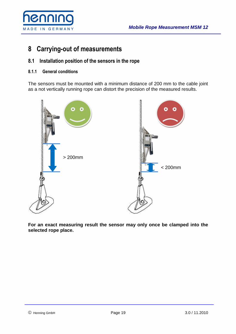
The sensors must be mounted with a minimum distance of 200 mm to the cable joint as a not vertically running rope can distort the precision of the measured results.
For an exact measuring result the sensor may only once be clamped into the selected rope place.
> 200mm
< 200mm

Mobile Rope Measurement MSM 12
Henning GmbH Page 20 3.0 / 11.2010
8.2 Rope adjustment
On principle, take care that the sensors are mounted in that section of the rope in which the rope exhibits a maximum length without intermediate deflections or traction sheaves, as the ropes during stoppage cannot or only slightly balance between the rope sections. If, due to the elevator design, this is only possible to some extent, several rope ad-justments one after the other have to be carried out. In this case the elevator must be moved several times in order to balance the ropes beyond the traction sheave, too.
1:1 Suspension

Mobile Rope Measurement MSM 12
Henning GmbH Page 21 3.0 / 11.2010
2:1 Suspension
Mobile Rope Measurement MSM 12
Henning GmbH Page 22 3.0 / 11.2010
8.3 Weight measurement
Due to heavy friction of the car or the counterweight in the rail guides the measuring result can be negatively influenced. In such a case it is better to de-termine the weight during a constant travel. This effect is found particularly frequently in the case of rucksack guides. In the case of roller guides in gen-eral this effect is found clearly less frequently than for slide guides If possible, clamp the sensors into the rope directly above the load to be measured (Distance >= 200 mm) and subsequently travel a short way upward. If there is no dif-ference between the indicated load during the constant travel and during standstill, the above mentioned friction in the guides does not exist and it is not necessary that you carry out the measurement during travel. If there is a significant difference between the travel and the standstill value, remem-ber the value during the upward travel and then start a downward travel with constant speed and read this value during the travel, too. The mean value of the upward and downward travel is the weight to be measured. By means of the trick of the upward and downward travel and the subsequent forma-tion of a mean value you have eliminated the kinetic and cohesive friction of the ele-vator from the measured value. In the case of multi-suspensions, please take special care that the sensors are not overrun during the travels!
9 Option: Bluetooth connection
9.1 Installation of the Bluetooth adapter
For the establishment of a wireless Bluetooth connection with the MSM12 rope load meter a Bluetooth adapter is required. If the computer is not equipped with such an adapter, you can use the factory-supplied Bluetooth adapter. Follow the instructions of the Windows XP operating system (and follow-up versions). These instructions will appear as soon as you have connected the Bluetooth adapter to your computer. Do not use the driver CD! In exceptional cases, dependent on your computer configuration, it can happen that the adapter is not automatically recognized and installed by the system. In such a case use the factory-supplied installation CD and follow the instructions of the instal-lation program. The operating instructions of the Bluetooth adapter are also found on the CD.

Mobile Rope Measurement MSM 12
Henning GmbH Page 23 3.0 / 11.2010
9.2 Bluetooth pairing
In order to use the wireless connection between the MSM12 and the computer the MSM12 must be paired with the computer. Here the pairing procedure under Win-dows XP with Service Pack 2 is described. For other operating systems the adjust-ments should be made correspondingly. As the PIN the rope load meter MSM12 uses the Bluetooth PIN
0000 (four times zero).
In order to connect the MSM12 to the computer, please switch it on. For this purpose press the on / off switch of the device for minimum 3 seconds. Now, the display shows the Henning logo.
Open the system control.
Search for the icon and start the window with a double click.
Click . [Add…]
Ensure that the MSM12 is switched on and put the check mark in the field
[Device has been set up and can be recognized]
and click . [Continue >] The computer is now searching for Bluetooth devices nearby.
Mobile Rope Measurement MSM 12
Henning GmbH Page 24 3.0 / 11.2010
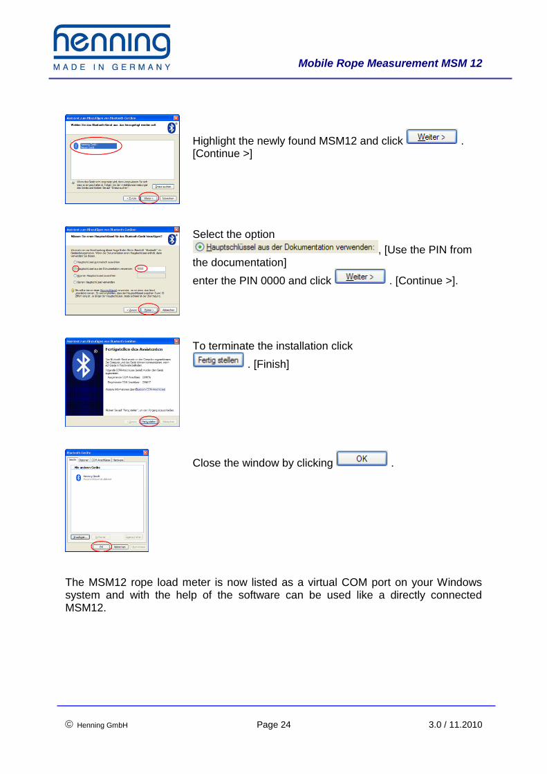
Highlight the newly found MSM12 and click . [Continue >]
Select the option
, [Use the PIN from the documentation]
enter the PIN 0000 and click . [Continue >].
To terminate the installation click
. [Finish]
Close the window by clicking .
The MSM12 rope load meter is now listed as a virtual COM port on your Windows system and with the help of the software can be used like a directly connected MSM12.
Mobile Rope Measurement MSM 12
Henning GmbH Page 25 3.0 / 11.2010
10 Technical Data Part number: 455 100 Dimensions L x W x H: 190 mm x 138 mm x 46 mm Weight: 650 g (incl. batteries) Interfaces: 1 x USB1.1 for the connection to a PC 12 x connections to the rope load sensor LSM 1 x connection for Bluetooth aerial (optional) Batteries: 4 x Alkali-manganese round cells (LR6, AA); or accumulators: 4 x NiMH AA 1.2 V min. 2,000 mAh Data transfer: Bluetooth Class 2 Degree of protection: IP 00 Class of protection: SKIII (SELV)
Henning GmbH Loher Str. 4 + 30 58332 Schwelm
Germany
Phone: +49 (0)2336 / 9 29 8 – 0 Fax: +49 (0)2336 / 9 29 8 – 10
eMail: [email protected]
URL : http://www.henning-gmbh.de/
Service-Hotline: +49 (0)2336 / 9 29 8 - 32