Embed Size (px)
Citation preview

MOBVIS FP6-511051 Deliverable Report
Vision Technologies and Intelligent Maps for Mobile Attentive Interfaces in Urban Scenarios Project co-funded by the European Commission
Sixth Framework Programme (2002-2006) Information Society Technologies
FP6-2002-IST-C / FET Open STREP
Due date of deliverable: May 31, 2006 (month 12) Actual submission date: June 15, 2006 Start date of project: May 1, 2005 Duration: 36 months Work package 5 – Intelligent Maps Task 2 – Geo-Information for Intelligent Maps Lead contractor for this deliverable JRS Editor Patrick Luley Authors Patrick Luley, Linde Vande Velde, Alexander
Almer, Rainer Prüller Quality reviewer KTH
Project co-funded by the European Commission within the Sixth Framework Programme (2002–2006)
Dissemination Level
PU Public X PP Restricted to other programme participants (including the Commission Services) RE Restricted to a group specified by the consortium (including the Commission Services) CO Confidential, only for members of the consortium (including the Commission Services)
D 5.1.1 “Specification of Intelligent Map Representations
and Report”

MOBVIS Deliverable D7.2.1 2
DOCUMENT HISTORY
Version Status Date Author 3 Input Tele Atlas 12.06.2006 Tele Atlas 1 First Template with content from JRS 31.05.2006 JRS
Final

MOBVIS Deliverable D7.2.1 3
CONTENT
DOCUMENT HISTORY........................................................................................................................... 2 CONTENT ............................................................................................................................................... 3 1. INTRODUCTION ................................................................................................................................. 5 2. BASIC MAP DATA FROM TA (BY TA)............................................................................................. 5
2.1 STANDARD MAP CONTENT USED FOR MOBVIS........................................................................... 5 2.1.1 Scope............................................................................................................................... 5 2.1.2 Tele Atlas MultiNet™....................................................................................................... 5
2.2 TECHNOLOGIES USED TO PROVIDE TA MAPS............................................................................. 12 2.2.1 Tele Atlas map server.................................................................................................... 12 2.2.2 GeoEngine..................................................................................................................... 20
3. MAP INTEGRATION PLATFORM (BY JR)...................................................................................... 22 3.1 BASIC MAPS NEEDED FOR MOBVIS GEOSERVICES .................................................................. 22 3.2 INTEGRATION OF DIFFERENT MAP-SOURCE (WMS, INTERFACES)................................................ 23
3.2.1 UMN Mapserver............................................................................................................. 23 3.2.2 Principle of OGC conform Web Services ...................................................................... 24 3.2.3 Operation as OGC conform Web Map Server............................................................... 25 3.2.4 Example of a map integration platform.......................................................................... 25 3.2.5 WMS data sources ........................................................................................................ 26
3.3 INTEGRATION OF MAP-FEATURE SOURCES (WFS, INTERFACES) ................................................. 28 3.3.1 Operation as OGC conform Web Feature Server ......................................................... 28
3.4 INTEGRATION OF MOBVIS SPECIFIC MAP OVERLAYS ................................................................. 28 4. INTELLIGENT MAPS (BY JR AND TA)........................................................................................... 29
4.1 GENERAL IDEAS AND BENEFITS OF INTELLIGENT MAPS (TA) ....................................................... 29 4.1.1 Market requirements...................................................................................................... 29 4.1.2 TA Strategy.................................................................................................................... 29 4.1.3 TA Enhanced Map Display Maps .................................................................................. 29
4.2 MOBVIS SPECIFIC IDEAS OF INTELLIGENT MAPS REGARDING TO USER SCENARIOS (TA).............. 30 4.2.1 Introduction enhanced Tele Atlas geo content required to support user scenarios ...... 30 4.2.2 Test area of Mobvis project ........................................................................................... 30 4.2.3 Tele Atlas enhanced map content and other geo content developed & offered for Mobvis 31
4.3 USING THE GEOGRAPHICAL AND LOGICAL CONTEXT OF A PERSON TO PREPARE INDIVIDUAL MAP CONTENT (JRS)................................................................................................................................... 41 4.4 TECHNOLOGIES TO GENERATE INTELLIGENT MAPS (TA)............................................................. 41
4.4.1 Traditional Data collecting methods .............................................................................. 41 4.4.2 Laser scan Technology ................................................................................................. 41 4.4.3 Tele Atlas Mobile Mapping Technology ........................................................................ 41 4.4.2 Technology to produce 3D Landmarks ......................................................................... 45 4.4.3 Technology to produce Tele Atlas Terrain Models........................................................ 45 4.4.4 Data volumes................................................................................................................. 46
4.5 IMPLEMENTATION CONCEPTS WITHIN THE MOBVIS SYSTEM ARCHITECTURE (JRS) ..................... 46 5. SUMMARY AND OUTLOOK ............................................................................................................ 46 6. ANNEX 1: WFS OPERATIONS: DETAILED DESCRIPTIONS ....................................................... 47
6.1 GETCAPABILITIES OPERATION .................................................................................................. 47 6.2 DESCRIBEFEATURETYPE OPERATION........................................................................................ 47 6.3 GETFEATURE OPERATION......................................................................................................... 48
7. ANNEX 2 ........................................................................................................................................... 49 7.1 GETCAPABILITIES OPERATION .................................................................................................. 49 7.2 GETMAP OPERATION................................................................................................................ 50 7.3 GETFEATUREINFO OPERATION ................................................................................................. 52

MOBVIS Deliverable D7.2.1 4
8. ANNEX 3: SAMPLE OF OLS GEOCODING.................................................................................... 53 9. REFERENCES.................................................................................................................................. 54

MOBVIS Deliverable D7.2.1 5
1. INTRODUCTION
This deliverable describes the actual status of theoretical and practical work within Task 5.1 (Geo-Information for Intelligent Maps). The deliverable considers results especially from Task 2.1 (Definition of Scenario and User Requirements) and further the needs within the work package 3 (Object and Event Awareness) and work package 4 (Context Awareness) for developments which are based on geo-information. The document includes a detailed illustration of the basic geo-information content and a specification of the interfaces to offer a standardised data access within the project. A further aspect is the detailed concept for the map integration platform which is defined as OGC conform solution. General ideas and benefits as well as implementation concepts within the MOBVIS system architecture are additional topics for this deliverable.
2. BASIC MAP DATA FROM TA (BY TA)
2.1 STANDARD MAP CONTENT USED FOR MOBVIS 2.1.1 SCOPE The scope of this paragraph is to give a high level data description of the Tele Atlas MultiNet and the external map data used for extended coverage.
2.1.2 TELE ATLAS MULTINET™ Tele Atlas MultiNet™ is the most detailed and comprehensive street network database. It is the basis for demanding applications such as turn-by-turn route guidance, traffic telematics, etc.
2.1.2.1 PRODUCT DOCUMENTATION Extensive product documentation (Data Specifications, Data Model Specifications, Format Specifications, Relational Model, Statistics, Product Information Tools, Release Notes, etc.) is available for each released product.
• Tele Atlas MultiNet™ Data Specifications: this manual describes the product content in general, such as the capturing rules of each feature etc.
• Tele Atlas MultiNet™ Data Model: this manual describes the way the data content is modelled in a product. A detailed content overview (features and attributes) can be found in the Appendixes of this document.
• Tele Atlas MultiNet™ Format Specifications: this document describes the format information on tables, record structure, etc.
2.1.2.2 FORMATS Tele Atlas MultiNet™ is available in 5 formats: GDF AS, GDF AR, Shapefile, Oracle Spatial Format and MapAccess Format
• The Tele Atlas MultiNet™ products in AS GDF format are fully compliant with GDF 3.0, the European approved (CEN) standard format for geographic data. They contain

MOBVIS Deliverable D7.2.1 6
all important features and attributes currently used in navigation applications. Additional relationships are included to ease conversion by the user.
• Tele Atlas MultiNet™ AR GDF format is the ASCII relational version of the GDF AS products. This product format contains exactly the same data as the sequential GDF, stored in relational ASCII tables. This saves a lot of time and effort during the import process - especially in applications that are based on a relational database.
• Tele Atlas MultiNet™ in Shapefile format offers the same content and coverage, structured according to a layered data model and in a standard GIS format. Layer and table design are optimised for direct use, for fast visualization and superior cartographic display, accurate geo-coding with top match rates and rapid optimal route calculation.
• Tele Atlas MultiNet™ in Oracle spatial format is also available. This Oracle format follows the same data model as the Tele Atlas MultiNet™ Shapefile. Together with the ASCII data which is ready for implementation into your Oracle system we provide customers with SQL scripts and batch software.
• Tele Atlas MultiNet™ in MapAccess format. The MapAccess format for Multinet™ databases is a highly compressed file format designed for fast access to and display of map information. MultiNet databases in MapAccess format (called MapAccess databases for simplicity) contain road network data in a highly compressed file format that allows applications to quickly find and display database information. MapAccess databases are a source of road and landmark data for map applications; they are not a source of geographic boundaries. MapAccess databases are typically used in geographic applications developed with MapAccess Development Tools. They are well-suited for applications that determine spatial relationships, display maps, or print maps. Accompanying the MapAccess databases are GeoIndex databases, which contain complete address information. Applications can use a GeoIndex database to determine the map locations for street addresses, and the addresses for latitude/longitude coordinates.The MapAccess format provides current address information and includes major landmarks,one-way street encoding in selected urban areas, richer graphics, shape points, and other enhancements.
2.1.2.3 CO-ORDINATE SYSTEM The co-ordinate system used is Longitude/Latitude, with ellipsoid WGS'84. Spherical coordinates are stored as decimal degrees.
2.1.2.4 TELE ATLAS COVERAGE PROFILES 2.1.2.4.1 MRNW-ICNW-STNW A coverage can be defined by different network types, respectively Major Road Network (MRNW), Interconnecting Network (ICNW) and Street Network (STNW):
• Major Road Network (MRNW): the network type available from Tele Atlas, covering the most important roads in a country.
• Interconnecting Network (ICNW): the intermediate network type of a Tele Atlas database, covering roads of high and medium importance. It contains all roads necessary to connect one municipality to another
• Street Network (STNW): the complete road network, it contains all roads (from highways to the smallest local streets), and is the most comprehensive network type with a Tele Atlas database.

MOBVIS Deliverable D7.2.1 7
In the overview underneath you can find the different road network types on the basis of the functional road classes (FRC): Major Road Network
From City to City 0 Motorways 1 Major Roads of High
Importance 2 Other Major Roads
Interconnecting Network
From Village to Village 0 Motorways 1 Major Roads of High
Importance 2 Other Major Roads 3 Secondary Roads 4 Local Connecting
roads 5 Local Roads of Major
Importance
Street Network All street details 0 Motorways 1 Major Roads of High
Importance 2 Other Major Roads 3 Secondary Roads 4 Local Connecting
roads 5 Local Roads of Major
Importance 6 Local Roads 7 Local Roads of Minor
Importance 8 Other Roads
2.1.2.4.2 BA-FA STNW In Tele Atlas MultiNet™, Street Network is split up in Street Network- Fully Attributed (STNWFA) and Street Network-Basic Attributed (STNW-BA).
• Basic attributed (BA): Tele Atlas basic attributed map data contain all basic features required for high quality navigation applications. These features include superior road network geometry, traffic directions, etc. Basic attributed map data fully comply with the highest quality standards at Tele Atlas. Most street names are already included in basic attributed data but full coverage cannot be guaranteed. Especially less important roads may not comply with the requirements of all demanding high-end applications, but most important roads, in general FRC 0-6, will be fully attributed.
• Fully attributed (FA): Tele Atlas fully attributed map data provide enhanced features for more sophisticated navigation capabilities, such as house number ranges, speed limits, inner city lane information, etc.

MOBVIS Deliverable D7.2.1 8
2.1.2.5 CONTENTS The contents of each individual product release can differ from the Specifications, because some features may not exist in a certain region or the database may not be fully completed for a certain region. The real availability of features and attributes in Tele Atlas MultiNet™ is for each released product.
2.1.2.6 OVERVIEW OF MAP ITEMS THAT CAN BE USED PER TYPE OF APPLICATION
TA MN Items that can be used for large scale mapping (WORLD MAP) Administrative Areas: high level Water elements: high level Country's Capital cities
TA MN Items that can be used for detailed mapping (TRAVEL GUIDE) Searching Map display Administrative Areas: lower level Built-up Areas Postal Districts Railways Roads & Ferries Water elements Street names Land cover/Land use information House number information Urban Agglomerations Address areas Index areas City centres POIs
TA MN Items that can be used for basic routing (TRAVEL GUIDE) Functional Road Class Special Restrictions on Roads Form of way of Roads Enclosed traffic areas Route Numbers Brunnels (bridges & tunnels) Special Charge Areas Bifurcations Roads with Blocked Passages Grade Separated Crossings Roads with Removable Blockages Manoeuvres Direction of traffic flow on roads Toll Roads Complex roads and intersections
TA MN Items that can be used for navigation (NAVIGATOR) Speed restrictions on roads Traffic signs Number of Lanes on roads Signpost information Lane information TMC Information
2.1.2.7 MORE IN DETAIL: FEATURES, ATTRIBUTES AND RELATIONS 2.1.2.7.1 Theme: General
• Centre Point of Feature • Names • Time related Information • Postal code information • Street Side • Validity Direction

MOBVIS Deliverable D7.2.1 9
• Unit of Measurement • Quality Mark
2.1.2.7.2 Theme: Roads and Ferries • Network Geometry • Road Nodes, Road Edges and Ferry Edges • Junctions, Road Elements and Ferry Connections • Intersections and Roads • Freeway Intersections • Address Area • Enclosed Traffic Area • Names for Roads and Ferries • Transportation Type • Plural Junctions • Blocked Passage • Direction of Traffic Flow • Form of Way • Freeway • Road Conditions • Functional Road Class • Net 1 Class • Net B Class • Net 2 Class • House Number Information • Route Number Information • Street Identifier • Special Restriction • TMC Information • Toll Information • Vehicle Type • Vehicle Restriction • Back Road • Construction Status • Ramp Information • Lane Information • Tourist Road • Carriageway Designator • Route Directional • Speed Restrictions • Special Charge
2.1.2.7.3 Theme: Road Furniture • Signpost Information • Traffic Sign
2.1.2.7.4 Theme: Administrative Areas • Administrative Areas • Administrative Places • Administrative Boundaries • Time Zone

MOBVIS Deliverable D7.2.1 10
2.1.2.7.5 Theme: Brunnels • Brunnels = Bridges & Tunnels
2.1.2.7.6 Theme: Railways • Railways • Railway Class
2.1.2.7.7 Theme: Settlements and Named Areas • Built-up Area • Postal District • Census District • Census • Elect Federal • Elect State Lower House • Elect State Upper House • Suburb • Index Area • Urban Agglomeration • Natives Reservation • Special Charge Area
2.1.2.7.8 Theme: Land Cover and Use • Land Cover and Use • Artificial Surface • Building • Forest and Semi-Natural Area • Island • Park/Garden
2.1.2.7.9 Theme: Waterways • Water Element • Water Centre Line • Water Display Class
2.1.2.7.10 Theme: Services See POIs.
2.1.2.7.11 Theme: Relationships • Relationships • Bifurcations • Grade Separated Crossing • Implicit Turn • Priority Manoeuvre • Prohibited Manoeuvre

MOBVIS Deliverable D7.2.1 11
• Restricted Manoeuvre • Lane Connectivity • Service Belonging to Service • Vicinity Relationship • Centre Point of Feature belonging to Feature • Feature in Order 8 Area • Feature in Order 9 Area • Feature in Built-up Area • Feature in Named Area • Service along Road Element • Service at Junction • Ferry Terminal along Ferry Connection • Traffic Sign along Road Element • Place within Place • Area replaced by Index Area • Road Edge belonging to Road Element • Ferry Edge belonging to Ferry Connection • Railway Edge belonging to Railway Element
2.1.2.7.12 Theme: Meta Information • Positional Accuracy • Geo-coding Accuracy Level • Processing Status • Road Geometry Completeness • Update Registration • Network Type • Major Road Feature • Tourist Municipality
For a detailed description about these features, attributes and relationship: see MultiNet Data Specifications 3.4.1 and MultiNet Data Model Specifications 3.4.1. A detailed content overview (features and attributes) can be found in the Appendices of the MultiNet Data Model Specifications.
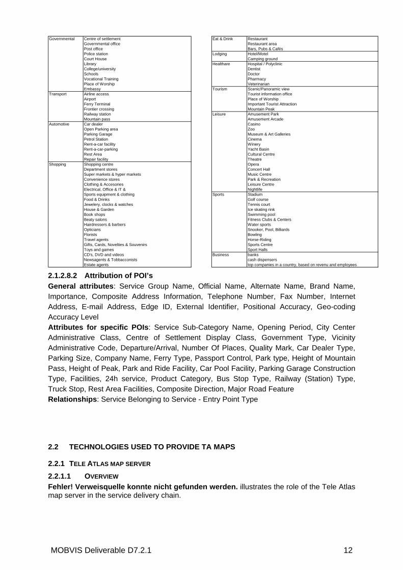
2.1.2.8 POINTS OF INTEREST (POI’S)
2.1.2.8.1 Themes & Categories
MOBVIS Deliverable D7.2.1 12
2.1.2.8.2 Attribution of POI’s General attributes: Service Group Name, Official Name, Alternate Name, Brand Name, Importance, Composite Address Information, Telephone Number, Fax Number, Internet Address, E-mail Address, Edge ID, External Identifier, Positional Accuracy, Geo-coding Accuracy Level Attributes for specific POIs: Service Sub-Category Name, Opening Period, City Center Administrative Class, Centre of Settlement Display Class, Government Type, Vicinity Administrative Code, Departure/Arrival, Number Of Places, Quality Mark, Car Dealer Type, Parking Size, Company Name, Ferry Type, Passport Control, Park type, Height of Mountain Pass, Height of Peak, Park and Ride Facility, Car Pool Facility, Parking Garage Construction Type, Facilities, 24h service, Product Category, Bus Stop Type, Railway (Station) Type, Truck Stop, Rest Area Facilities, Composite Direction, Major Road Feature Relationships: Service Belonging to Service - Entry Point Type
2.2 TECHNOLOGIES USED TO PROVIDE TA MAPS
2.2.1 TELE ATLAS MAP SERVER 2.2.1.1 OVERVIEW Fehler! Verweisquelle konnte nicht gefunden werden. illustrates the role of the Tele Atlas map server in the service delivery chain.
Governmental Centre of settlement Eat & Drink RestaurantGovernmental office Restaurant areaPost office Bars, Pubs & CafésPolice station Lodging Hotel/MotelCourt House Camping groundLibrary Healthare Hospital / PolyclinicCollege/university DentistSchools DoctorVocational Training PharmacyPlace of Worship VeterinarianEmbassy Tourism Scenic/Panoramic view
Transport Airline access Tourist information officeAirport Place of WorshipFerry Terminal Important Tourist AttractionFrontier crossing Mountain PeakRailway station Leisure Amusement ParkMountain pass Amusement Arcade
Automotive Car dealer CasinoOpen Parking area ZooParking Garage Museum & Art GalleriesPetrol Station CinemaRent-a-car facility WineryRent-a-car-parking Yacht BasinRest Area Cultural CentreRepair facility Theatre
Shopping Shopping centre OperaDepartment stores Concert HallSuper markets & hyper markets Music CentreConvenience stores Park & RecreationClothing & Accesories Leisure CentreElectrical, Office & IT & NightlifeSports equipment & clothing Sports StadiumFood & Drinks Golf courseJewelery, clocks & watches Tennis courtHouse & Garden Ice skating rinkBook shops Swimming poolBeaty salons Fitness Clubs & CentersHairdressers & barbers Water sportsOpticians Snooker, Pool, BilliardsFlorists BowlingTravel agents Horse-RidingGifts, Cards, Novelties & Souvenirs Sports CentreToys and games Sport Halls CD's, DVD and videos Business banksNewsagents & Tobbacconists cash dispensersEstate agents top companies in a country, based on revenu and employees

MOBVIS Deliverable D7.2.1 13
Content Aggregation
Appl. Service
Provision
Static and dynamic
third party content
Map database
Web Map Service
Web Feature Service
Location Utility
Service
…
Other services
Application 3Application 2Application 1
Tele Atlas map server
Figure 1: Role of Tele Atlas map server in service chain
The major component of the Tele Atlas map server is a digital map database with a global coverage. The underlying data model is GDF[1]. At the output side, the Tele Atlas map server provides the map content via industry standard interfaces from the OpenGIS consortium in various formats to enable a wide range of services. In particular, the web feature service for vector data in GML [2] and the web map service for raster maps in various image formats are supported. In addition a subset of the location utility service from the OpenGIS Location Services is supported to provide geocoding and reverse geocoding functionality. The following sections describe these three interfaces more in detail.
2.2.1.2 TELE ATLAS MULTINET The database schema for the underlying Tele Atlas map corresponds to the schema of the Tele Atlas MultiNet Oracle product. As this schema is proprietary, it will not be disclosed here in full detail. Instead, the general structure and content is reported. Tele Atlas MultiNet contains detailed traffic and address attribute information, unparalleled positional accuracy, superior geocoding capability, and additional features. MultiNet's unique features and attributes drive users location-related applications, ranging from GIS software to turn-by-turn navigation. Geometry capabilities provide: centrelines for all drivable roads and streets, railways, ferry lines, and rivers; polygons for lakes, land cover, administrative areas, and postal districts; point features for city centres, junctions, points of interest, etc. Geocoding attributes include: administrative structure (country, municipality, province), street names, alternate street names, house-number ranges, postal codes, address areas, etc. Routing Attributes provide: functional road class, form of way, route numbers, direction of traffic flow (one-way, two-way, divided motorway), road condition, network classifications, blocked passages, special restrictions, restricted manoeuvres, toll roads, etc.

MOBVIS Deliverable D7.2.1 14
Navigation Attributes provide: information on complex intersections, z-levels for bridges and tunnels, signpost information, tourist roads, TMC locations and paths, etc. For details of the structure of the Tele Atlas MultiNet: see chapter 2.1
2.2.1.3 WEBFEATURE SERVICE INTERFACE The ‘OpenGIS
Web Feature Service Implementation Specification’ [4] defines several
interfaces describing data manipulation operations on geographic features using the hypertext transport protocol (HTTP) as the distributed computing platform. The data manipulation operations include the ability to: Create a new feature instance Delete a feature instance Update a feature instance Get or Query features based on spatial and non-spatial constraints A Web Feature Service request consists of a description of query or data transformation operations that are to be applied to one or more features. The request is generated on the WFS client and is posted to a web feature server by using HTTP. The web feature server reads and executes the request and sends the result back to the WFS client (Figure 2).
Figure 2: Web feature service architecture
The requirements for a Web Feature Service are as follows: 1. The interfaces must be defined in XML. 2. GML must be used to express features within the interface. 3. At minimum a WFS must be able to present features using GML. 4. The predicate or filter language will be defined in XML and be derived from CQL as
defined in the OpenGIS Catalogue Interface Implementation Specification. 5. The datastore used to store geographic features should be opaque to client applications
and their only view of the data should be through the WFS interface. 6. A subset of XPath expressions shall be used for referencing properties. To support transaction and query processing, the following individual operations are defined: GetCapabilities: A web feature service must be able to describe its capabilities. Specifically, it must indicate which feature types it can service and what operations are supported on each feature type. DescribeFeatureType: A web feature service must be able, upon request, to describe the structure of any feature type it can service. GetFeature: A web feature service must be able to service a request to retrieve feature instances. In addition, the client should be able to specify which feature properties to fetch and should be able to constrain the query spatially and non-spatially.

MOBVIS Deliverable D7.2.1 15
Transaction: A web feature service may be able to service transaction requests. A transaction request is composed of operations that modify features; that is create, update, and delete operations on geographic features. LockFeature: A web feature service may be able to process a lock request on one or more instances of a feature type for the duration of a transaction. This ensures that serializable transactions are supported. Based on the operation described above, two classes of web feature services are distinguished: Basic WFS: A basic web feature service does implement the GetCapabilities, DescribeFeatureType and GetFeature operations. This is considered as a READ-ONLY web feature service. Transaction WFS: A transaction web feature service does support all the operations of a basic web feature service. In addition it implements the Transaction operation, for creating, updating, and deleting geographic features. Optionally, a transaction WFS can implement the LockFeature operation. The Tele Atlas map server implements a basic WFS interface towards the delivery platform. The necessary operations are described in more detail in the following sections. See Annex 1:
2.2.1.4 GML APPLICATION SCHEMA The Geographic Markup Language [2] is an XML grammar written in XML Schema [3] and suitable for encoding geographic information and features that are geographically referenced. It provides a base schema for representing objects, features and their geometric, topologic, or temporal properties. GML does not provide a predefined feature catalogue or a standard data model. Instead, each GML user can develop an own feature catalogue and use an own data model writing a new ad hoc application schema. The map server delivers GML according to an application schema that is based on the GDF data model for geo-spatial content.
2.2.1.5 WEB MAPPING SERVICE INTERFACE ‘Web Mapping Service’ (WMS) is an Open GIS specification [5, 6] and draft ISO standard. It specifies interfaces for an internet-based map server to supply rendered map images in various formats. Any WMS compliant map server that implements the OpenGIS WMS Specification needs to supply three WMS operations: GetCapabilities, GetMap, and GetFeatureInfo (optional). A WMS-compliant Web client is a Web application/program that communicates with WMS servers using those three functions.
GetCapabilities
A GetCapabilities Request (GetCapabilities XML file) retrieves metadata about a WMS server indicating its abilities (request parameters) and data holdings/services (the area extent covered, thematic layers, and styles available) to requesting Web clients. Data are formatted according to the Capabilities Document Type Definition. In response to a client's GetCapabilities request, the WMS server produces an XML file containing the map server's service metadata. The Web client application has to read the XML capabilities document to retrieve the information necessary to issue a GetMap request. A WMS server must be able to deliver this XML metadata file via HTTP upon receiving a GetCapabilities request.
GetMap
After a GetCapabilities request confirms that the server can produce a valid XML GetCapabilities response, the client can execute a GetMap request. The GetMap request allows the Web client to specify (according to the GetCapabilities XML file) the distinct data layers and styles, spatial reference system, geographic area, and other parameters

MOBVIS Deliverable D7.2.1 16
describing the format of the returned map. On receiving the GetMap request, a WMS server will return a map image in either JPEG, GIF, GML, or other format.
GetFeatureInfo
After getting a map, the Web client can then request the feature data about a specific point on the map by constructing the GetFeatureInfo request by adding parameters to the map URL specifying a location (such as an x-y offset from the upper left corner) and the number of nearby features about which the WMS server should return information. The response from the WMS server can be a text, XML/GML, HTML, or Word file containing attribute information for the selected feature(s). The resulting map can also be presented as an HTTP image map so that the user can click on a specific point of the map to get more feature information. If a WMS server supports this operation, its maps are said to be queryable. The WMS server must be able to deliver a map via HTTP upon receiving a WMS client request . As a reply, the map in Fehler! Verweisquelle konnte nicht gefunden werden. is provided.
Details on the WMS operations can be found in Annex 2.
Figure 3: Sample map reply (Graz)
2.2.1.6 OPENLS LOCATION UTILITY SERVICE INTERFACE Launched in 2000 by the OpenGIS Consortium (OGC), the OpenLS Initiative was set to allow the successful provision and integration of geospatial data and geoprocessing resources into the location services and telecommunications infrastructure.

MOBVIS Deliverable D7.2.1 17
Major interface specifications (APIs) defined in the OLS specification [4] are: - Navigation Services. - Directory Services (POI.) - Presentation Services. - Location Utility Services.
- Geocoding. - Reverse Geocoding.
- Gateway services. - Encoding & Protocols.
- XML for Location Services. - Interface Encoding.
The Tele Atlas map server will support a subset of the location utility services towards the delivery platform. This service performs as a geocoder by determining a geographic position, given a place name, street address or postal code. It also returns a complete, normalized description of the place (which is useful, say, when only partial information is known). The service also performs as a reverse geocoder by determining a complete, normalized place name/street address/postal code, given a geographic position. Both the geocoder and reverse geocoder may return zero, one, or more responses to a service request depending on the match criteria. For both services, the following abstract data types (ADT) are relevant:
Address ADT Contains address information for a geographic place. Addresses reference and uniquely identify particular points of interest and can serve as the basis for aggregating data for that location. The Address ADT consists of a street address (or intersection), place name (e.g. country, municipality, etc.), postal code, street locator, building locator, and supplemental address information. As used here, addresses are the means of referencing primarily residences and buildings (of all types, where a subscriber may conduct business).
Area of Interest (AOI) ADT Contains an Area of Interest as defined by a named circle, bounding box, or polygon. Used to as a search parameter or can be displayed for a subscriber (e.g. Hot Zone).
Position ADT Contains any observed or calculated position, in the broad semantic context of the use of the term. It primarily contains a geographic position and quality of position. Position is the primary output from a Gateway Service. Position maps to the semantics of the Location, Shape and Quality of Position elements, as defined in the Mobile Location Protocol (MLP) Specification (Version 3.0, OMA). Thus, it contains the full definition of a position of a Mobile Terminal (Standard Location Immediate Service). Position may also be used by an OpenLS application to represent any position of interest. Position is distinguished from POI, which is a well-known place with a position, name, address, etc.
MOBVIS Deliverable D7.2.1 18
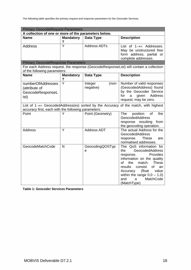
The following table specifies the primary request and response parameters for the Geocoder Services.
Primary GeocodeRequest Parameters A collection of one or more of the parameters below. Name Mandatory
? Data Type Description
Address Y Address ADTs List of 1→∞ Addresses. May be unstructured free form address, partial or complete addresses.
Primary GeocodeResponse Parameters For each Address request, the response (GeocodeResponseList) will contain a collection of the following parameters: Name Mandatory
? Data Type Description
numberOfAddresses (attribute of GeocodeResponseList)
Y Integer (non-negative)
Number of valid responses (GeocodedAddress) found by the Geocoder Service for a given Address request; may be zero.
List of 1→∞ GeocodedAddress(es) sorted by the Accuracy of the match, with highest accuracy first, each with the following parameters: Point Y Point (Geometry) The position of the
GeocodedAddress response resulting from the geocoding operation.
Address Y Address ADT The actual Address for the GeocodedAddress response. These are normalised addresses.
GeocodeMatchCode N GeocodingQOSType
The QoS information for the GeocodedAddress response. Provides information on the quality of the match. These results consist of an Accuracy (float value within the range 0.0 – 1.0) and a MatchCode (MatchType)
Table 1: Geocoder Services Parameters

MOBVIS Deliverable D7.2.1 19
The following table specifies the primary request and response parameters for the Reverse Geocoder Services.
Primary ReverseGeocodeRequest Parameters Name Mandatory
? Data Type Description
Position Y Position ADT The starting position (lat,long) for Reverse Geocoder.
SearchArea N AOI ADT Area to restrict the search for addresses. Can be a Circle, Polygon or Box. This function can be used as an approach to narrow down candidates or widen the area of search. It is independent of the position shape.
ReverseGeocodePreference
N ReverseGeocodePreferenceType
Describes the preference for the response from the Reverse Geocoder Service: StreetAddress, IntersectionAddress, or PositionOfInterest (Place and/or PostalCode). If not specified, then the service will return the nearest StreetAddress.
Primary ReverseGeocodeResponse Parameters Name Mandatory
? Data Type Description
List of 0→∞ ReverseGeocodedLocation(s) sorted by the SearchCentreDistance (the distance between the starting Position in the request and each Point-Address response), in order (with shortest distance first), where each ReverseGeocodedLocation has the following parameters: Address Y Address ADT The actual Address for the
ReverseGeocodedLocation response. These are normalised addresses.
Point Y Point (geometry) The position (lat, long) of the ReverseGeocodedLocation response.
SearchCentreDistance
N Float (decimal metres)
Distance of Point from starting Position.
Table 2: Reverse Geocoder Services Parameters
Annex 3 contains a sample of OLS geocoding request using the schema above.
2.2.1.7 HARDWARE AND SOFTWARE ENVIRONMENT All data is stored in an Oracle database system. The software components all run under Java. This imposes relatively high requirements on the hardware and software environment. The underlying server is physically located at Tele Atlas, and can be reached via the Internet. The server is running on the following hardware:
• HP Proliant DL380 R4 server

MOBVIS Deliverable D7.2.1 20
• 2x 3.2 GHZ Intel Xenon processor • 4 GB RAM • 143 GByte Harddisk as RAID1
The server runs the following operating system and software components:
• Linux SuSE 9.2 • Oracle 10g Enterprise Edition with Spatial data option (Version 10.2) • Java 2 Enterprise Environment (J2SDK 1.5.0_04) • Apache Tomcat/5.5.16 servlet engine • Geoserver 1.3 servlet • Self-implemented servlets
2.2.2 GEOENGINE
2.2.2.1 INTRODUCTION TO GEOENGINE GeoEngine is a modular development environment (SDK) developed by Tele Atlas and used for the development of mapping applications. GeoEngine supports all functional areas relevant for navigation and LBS applications, such as map display, route planning, geocoding and reverse geocoding. GeoEngine has a proprietary protocol between server and client, which is optimised for fast access and good performance. Using the GeoEngine sample code allows the developers to develop a new application in a rapid way, and the resulted map application has a very good performance. It includes the following features:
• Platform dependencies (hardware/OS) are isolated in one component. • GeoEngine can support multiple components for reading map data (DALs). • Provides components for general map rendering and dynamic labeling, with extensive
configuration controls. • Provides components to manage application defined overlay data. • Provides components to support client/server communication of map data in either a
binary or xml format. • Support for graphic output, such as bitmap, gif, Windows metafile, Targa. • Support for pkzip/gzip archives. • Additional functionality available for the MapAccess data format, pathfinding and
routing, Geocoding, and Navigation (positioning). 2.2.2.2 DOCUMENTATION GEOENGINE The manuals serve as a general introduction to GeoEngine. For information specific to GeoEngine modules, plug-ins, and utilities, following documents are available:
• GeoEngine Mapping Toolkit Overview: Explains how to use the GeoEngine Mapping Toolkit. Includes map concepts, basic GeoEngine concepts, and a GeoEngine glossary of terms. This manual should be used in conjunction with all other GeoEngine functional reference documentation.
• Core Module API • Windows Module API or UNIX Module API • Display Module API: These functional reference books explain the foundational
GeoEngine modules used by most GeoEngine applications. Together, these three modules provide basic services such as map interpretation, memory allocation, and map print/display capability.
• GeoEngine Demonstration Program: Explains how to use the demonstration program included with the GeoEngine Mapping Toolkit. The program illustrates much of the GeoEngine module functionality.

MOBVIS Deliverable D7.2.1 21
• Geocoding Plug-in: Explains how to implement the Geocoding Plug-in. This plug-in geocodes-- finds the latitude and longitude coordinates for a given address – and reverse geocodes -- finds an address from given latitude and longitude coordinates. The Geocoding Plug-in enables both interactive and batch geocoding.
• Navigation Plug-in : Describes how to use the GeoEngine Navigation Plug-in with navigation sensors to enable vehicle navigation.
• Pathfinding Plug-in : Describes the Pathfinding Plug-in, which enables applications to find the best path between two points and to get directions for traveling the path.
• GeoEngine Utilities : Describes special utilities included with GeoEngine. Utilities can overlay points, lines, areas, and circles on a map, speed map display when wide lines predominate, save an image to the Windows clipboard, and save an image to a bitmap. Utilities also includes a resource file containing the standard set of icons used by GeoEngine.
2.2.2.3 RELATION BETWEEN GEOENGINE AND OGC STANDARDS GeoEngine offers already a full solution and there is as such no need to be compliant with OGC standards. GeoEngine supports all functional areas relevent for navigation and LBS applications, such as map display, route planning, geocoding and reverse geocoding. GeoEngine has an proprietary protocol between server and client, which is optimised for fast access and good performance. Using the GeoEngine sample code allows the developers to develop a new application in a rapid way, and the resulted map application has a very good performance. Tele Atlas is able to provide digital map data in the MAP ACCESS format supporting the Geoengine. Using OGC standards, has as advantage that it is open and interoperable, but no full solution can be provided easily. The developer has to gather all the components himself, maybe from open source or even commercial domain. In addition it is for sure that the performance of the client applications built with OGC standards are much more lower then when using the Geoengine full solution, as OGC require webbased interfaces.Using OGC standards means also map data to be offered and supported in GML. Right now Tele Atlas does not support GML as standard product. If there are other reasons to comply to OGC, such as involving data or services from other sources than Tele Atlas, we recommend to solve this issue at client side. I.e. to implement a Mobvis client based on GeoEngine and extend ith with OGC suppoprt to access the other data/services. To conclude, we recommend to use GeoEngine at both sides, client and server side to access Tele Atlas data, for the main reasons that a full solution is already offered and that the map application development time will be much faster then using the OGC standards, and that the performance will be much more better.
2.2.2.4 HARDWARE REQUIREMENTS OF APPLICATION SERVER AND MAP DATA SERVER The map database and data server application may reside on any Windows machine. The GeoEngine applications works well on all hardware platforms. It was originally designed on machines that ran at 64MHz running Windows 3.1 So current harware is orders of magnitude faster. The real bottelneck is the server communication and how the application makes use of it. All of this is outside of GeoEngine. Any server that is considered adequate to host web pages with high traffic is fine for a GeoEngine application. The client application may reside on any Windows or Windows-CE machine (arm/sh3/emulation). (UNIX - has not been exercised for some time and may require updates).

MOBVIS Deliverable D7.2.1 22
A client application on a Windows CE device will probably need 3-4 Mb of memory. This includes space for program code and temporary map data that is downloaded to the client to support local display user interaction.
Figure 4: Example: Application server versus map data server for tablet PC and PDA
2.2.2.5 REQUIRED OPERATING SYSTEM Applications can be developed on a variety of development platforms including C, C++ and Visual Basic. GeoEngine supports Windows 95, 98, 2000, NT operating systems and Windows CE platforms.
2.2.2.6 PROGRAMMING LANGUAGE The modules are written in C, and are highly portable (except OS specific module). In the Windows environment, GeoEngine is provided as either static libraries or DLLs. Applications that use GeoEngine can be written in most high level languages: C/C++, Visual Basic, Delphi, C++ Builder, Java. The binary footprint is very small. Run time memory overhead (data) is typically about a 1 Mb or less to manage a map display. Multiple displays are easy to do, add very small additional overhead, and are designed to be thread safe in a multithreaded environment such as Windows.
3. MAP INTEGRATION PLATFORM (BY JR)
3.1 BASIC MAPS NEEDED FOR MOBVIS GEOSERVICES For visualisation of vector information from TA (see chapter Fehler! Verweisquelle konnte nicht gefunden werden.) additional geodata is necessary for orientation in a map. So as background satellite and aerial images are used. In MobVIS for the inner city of Graz an orthophoto (Figure 5) and a city map, both with a 2 m resolution are used. These are raster images in the UTM 32 projection.

MOBVIS Deliverable D7.2.1 23
Figure 5: Inner City of Graz with Schlossberg and Hauptplatz To embedding those enables the user to establish a spatial context to the shown vector based geodata, like Points of Interests (POIS) or tracks. In Figure 6 the visualisation area of MobVIS, the Inner City of Graz is shown; it is a 1 km x 1 km area.
Figure 6: MobVIS visualisation area: Inner City of Graz
In addition to the aerial photo and the city map Geoinformation from Tele Atlas will be added, like street names, POIS and some further information.
3.2 INTEGRATION OF DIFFERENT MAP-SOURCE (WMS, INTERFACES)
3.2.1 UMN MAPSERVER As basic technology for the integration of different map-sources the Mapserver of the University of Minnesota is used. The UMN Mapserver software was created in the year 1994 from Steve Lime as a very simple web application within a bigger project. In the following five years the technology was free available via a homepage of the University of Minnesota. In the year 1999 the DM Solutions Group from Ottawa, Canada discovered the UMN Mapserver and fitted it as their solution for commercial web-mapping applications. As the requirements were increasing, the UMN Mapserver technology grew erratic and led to a respectable community of developers and a respectable number of applications in the web.

MOBVIS Deliverable D7.2.1 24
The basic function of the UMN Mapserver is shown in Figure 7. A user communicates with his browser via HTTP with a webserver which holds data for the internet. In case of a geodata request the webserver refers to the UMN Mapserver which sends in response a map as a raster image via HTML. The configuration of the UMN Mapserver is made by the mapfile which controls the portrayal of the map in the browser. The UMN Mapserver is fed with geodata which can exist in different formats and projections.
Figure 7: Function of the UMN Mapserver
The UMN Mapserver is in principle able to involve geodata from files, raster catalogues, databases and Web Map Services. These different data sources can have miscellaneous projects and must not be stored at one geodata server; they can be distributed in the web and for instance implemented by WMS. One example of the implementation is shown in Figure 11.
3.2.2 PRINCIPLE OF OGC CONFORM WEB SERVICES Web Services are modular built applications, which offer usere a closed functionality for data transfer via the Internet. Through the use of XML Web Services aren’t bound to operating systems or programming languages. In Figure 8 the principle of OGC Web Services with following function diagram is shown. The client contacts via Internet the geodata server and asks for a Capabilities-Document, in which the available geodata are described The server responses a XML-formatted Capabilities-Document of the desired Web Service to the client The client requests available geodata from the server The server transmits the requested geodata These four steps is the basic functionality of a Web Service defined by OGC specifications.
Figure 8: Principle of OGC conform Web Services

MOBVIS Deliverable D7.2.1 25
3.2.3 OPERATION AS OGC CONFORM WEB MAP SERVER The UMN Mapserver is able to run as OGC conform Web Map Server. So it is possible to make the data used in the WebGIS application via a standardised interface public. The user is so able to access the geodata, as output a raster image is generated and sent back. In Figure 9 the WEB section of a minimal Web Map Server within an UMN Mapserver map file is shown. It is necessary to define a name for the Web Map Service and a path to the map file of the application.
Figure 10: WEB Section of a „minimal” Web Map Server
3.2.4 EXAMPLE OF A MAP INTEGRATION PLATFORM In Figure 8 an existing map integration platform based on the UMN Mapserver is shown. This application is running on a client programmed with HTML and JavaScript, in which the elements produced by the Mapserver are integrated. These elements are the map itself, a scale bar, a legend and a reference map as graphics and some more information like the coordinates of the mouse pointer and the approximate scale of the map on the screen. Further information about the map can be accessed by the Information-Button.

MOBVIS Deliverable D7.2.1 26
Figure 11: Map integration platform based on the UMN Mapserver
The client offers beside standard navigation functions like zooming and panning some GIS functionalities like the measuring of distance or the query of vector objects. These functions can be activated by choosing a tool from the toolbar.
3.2.5 WMS DATA SOURCES As good tested example for a WMS implementation, which could be used for MobVIS, is the public provider from geodata in the district of Styria “GIS-Steiermark”. In the GetCapabilities-Request, as seen in Figure 12, the available layers are described.
Figure 12: GetCapabilities Request from GIS-Steiermark The problem is that not all layers shown in the Capabilities document are useable as described. So it is necessary to test each of the mentioned layers. The result of this test are the useful layers shown in Table 3.

MOBVIS Deliverable D7.2.1 27
Name of the layer Description
Bezirke Districts in Styria Gemeinden Municipalities in Styria, from 1:200000 Haltestellen Stops of public transports, from 1:10000 Luftbilder_SW_Verfuegbarkeit Availability of panchromatic aerial photos Luftbilder_Farbe_Verfuegbarke Availability of multispectral aerial photos Nutzungsflaechen Land use areas, from 1:10000 OeK500 Austrian map 1:500000 OeK200 Austrian map 1:200000 OeK50 Austrian map 1:50000 Ortsbezeichnungen Capitals of the districts in Styria Steiermark_Maske Borders of Styria Straßenbezeichnung Names of roads
Table 3: Useable layers in GIS-Steiermark
As can be seen from Table 3 very different data can be implemented by Web Map Services. GIS Steiermark offers different services which include these layers. They can be stored in different projections, in different formats and on different servers. The Web Map Server has to merge them into one project so that a client is able to access them with an OGC conform request. The UMN Mapserver has an operational mode implemented which allows running as Web Map Server. Therefore some specifications have to be done which are mentioned above. The implementation of the basic Austrian map “OEK200” from this server is shown in Figure 13. After the GetMap-request parameters are defined which describe the desired map section.

MOBVIS Deliverable D7.2.1 28
Figure 13: Geodata implementation from GIS Steiermark
3.3 INTEGRATION OF MAP-FEATURE SOURCES (WFS, INTERFACES) Where Web Map Services (WMS) have the opportunity to request Capabilities, to show maps and to give information about the data the application is based on, Web Features Services (WFS) offer an interface, which allows the user to influence the based data. It is possible to change, delete and add new objects in a map. The UMN Mapservers is not yet able to support the change of data, it is only able to produce maps. But it has the ability to provide vector information with the transport technology of WFS and to include data from a WFS source. The UMN Mapserver is at time not yet able to communicate with Web Feature Server sending their data with the HTTP-method ‘POST’ like all products from the company ESRI do. Mapserver is able to handle GetCapabilities-, DescribeFeature- and GetFeature-requests from the defined one in the OGC Web Feature Service specification.
3.3.1 OPERATION AS OGC CONFORM WEB FEATURE SERVER The UMN Mapserver is only able to portray vector layers in its WFS-Capabilities, for example the common ones like shape files, PostGIS data. This includes that the parameter TYPE in the LAYER section of the map file has to be set on POINT, LINE or POLYGON. For the implementation of data from a PostgreSQL/PostGIS database the parameter DUMP has to be set on TRUE which allows the UMN Mapserver to response data in the GML format (Figure 14). The WEB section looks quite similar to the WMS one (Figure 15).
Figure 14: LAYER Section of a „minimal” Web Feature Server
Figure 15: WEB Section of a „minimal” Web Feature Server
3.4 INTEGRATION OF MOBVIS SPECIFIC MAP OVERLAYS

MOBVIS Deliverable D7.2.1 29
4. INTELLIGENT MAPS (BY JR AND TA)
4.1 GENERAL IDEAS AND BENEFITS OF INTELLIGENT MAPS (TA)
4.1.1 MARKET REQUIREMENTS Next to the growing car-navigation market, the market of Location Based Services (LBS) applications is growing very fast. It is expected that this application area in the near future will develop into a mass market. The currently available digital maps are the source for both expanding markets. However, mobile LBS application providers and car-navigation providers give indications that improved map display is required.
4.1.2 TA STRATEGY Tele Atlas maps allow end users to accurately FIND locations and optimally GUIDE them between origin and destinations with an intuitive DISPLAY. Find enables end users to link to the world through the map, helping them locate places, people and products. Guide is the ability to generate accurate and safe routes in real time with clear, audible and/or visual instructions. Display is the ability to optimally visualize reality to enhance the end user experience.
4.1.3 TA ENHANCED MAP DISPLAY MAPS The request to have an improved map display resulted in the development of City Maps. The Tele Atlas City Maps are enhanced digital road network maps containing area features such as the building footprints and sidewalks. In addition to the enhanced map display, these City Maps improve the navigation functionalities. City Maps help the drivers and pedestrians to improve their orientation. However, application builders will not stop working at this level. Together with map providers, they prototype 3D map display. This will not only enrich the functionalities of the fancy navigation systems but it also opens a complete new world for the development of various 3D GIS and Navigation applications.

MOBVIS Deliverable D7.2.1 30
There are different types of 3D maps, different levels of detail and different ways to generate 3D maps. The main goal is to generate 3D maps in such a way that they are cost-efficient, highly accurate and easily maintainable. For each required level of detail there are different sources which used to generate building height in a semi-automatically way. Since no field data capturing is required during this semi-automatically process, cost-efficient generic 3D City Maps can be generated [10]. But as soon as building textures are required, field data capturing is a necessity. In order to generate those enriched 3D City Maps the geo-coded image sequences acquired by the Tele Atlas Mobile Mapping Vehicles are a valuable source. They allow mapping front texture and roof type information.
4.2 MOBVIS SPECIFIC IDEAS OF INTELLIGENT MAPS REGARDING TO USER SCENARIOS (TA)
4.2.1 INTRODUCTION ENHANCED TELE ATLAS GEO CONTENT REQUIRED TO SUPPORT USER SCENARIOS
In the framework of the Mobvis project Tele Atlas defined and described new enhanced map content required to support Mobvis user scenario services (D2.1). Tele Atlas also provides other types of Geocontent, such as aerial pictures not standard offered as Tele Atlas products.
4.2.2 TEST AREA OF MOBVIS PROJECT The standard content and the enhanced content is offered for a specific predefined test area in Graz (Austria).
Figure 16: Test area Mobvis

MOBVIS Deliverable D7.2.1 31
4.2.3 TELE ATLAS ENHANCED MAP CONTENT AND OTHER GEO CONTENT DEVELOPED & OFFERED FOR MOBVIS
4.2.3.1 2D CITY MAP OF GRAZ • 2D City map (building footprints and sidewalks) for complete test area • The 2D City maps will be provided in Oracle, Shape format an MapAccess Format
Figure 17: Result 2D city Map of Graz Area
4.2.3.2 ENHANCED 3D CITY MAP
• Basic 3D City Map Product: Building heights for complete test area + Roof type for complete test area
• Enhanced 3D City Map product: Is the Basic 3D City Map product and Façades for the buildings located in test area: There will be 3 different types of LOD facades. Where LOD1 are generic facades, LOD2 where ground floor is photo realistic and where LOD3 has Facades with a complete photo realistic texture.

MOBVIS Deliverable D7.2.1 32
Figure 18: overview LOD’s in Graz.
• The basic and enhanced 3D city maps will be provided in Oracle, Shape and
MapAccess Format
Figure 19: Result Basic 3D city map of Graz area
MOBVIS Deliverable D7.2.1 33
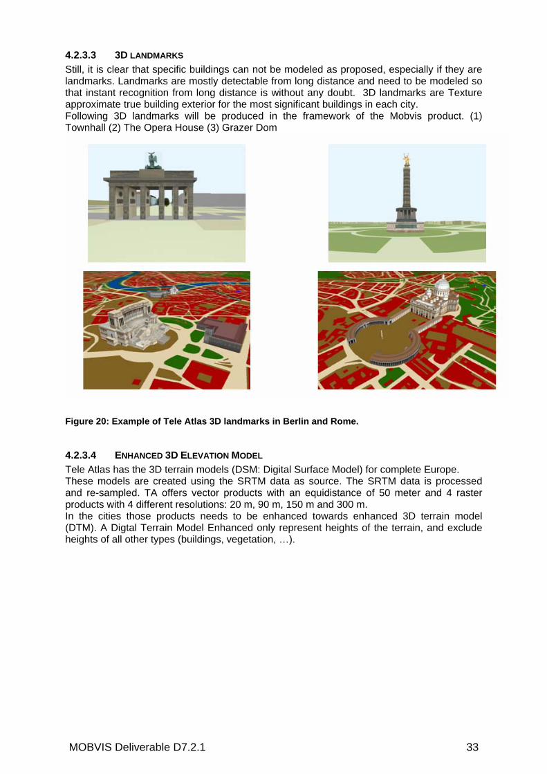
4.2.3.3 3D LANDMARKS Still, it is clear that specific buildings can not be modeled as proposed, especially if they are landmarks. Landmarks are mostly detectable from long distance and need to be modeled so that instant recognition from long distance is without any doubt. 3D landmarks are Texture approximate true building exterior for the most significant buildings in each city. Following 3D landmarks will be produced in the framework of the Mobvis product. (1) Townhall (2) The Opera House (3) Grazer Dom
Figure 20: Example of Tele Atlas 3D landmarks in Berlin and Rome.
4.2.3.4 ENHANCED 3D ELEVATION MODEL Tele Atlas has the 3D terrain models (DSM: Digital Surface Model) for complete Europe. These models are created using the SRTM data as source. The SRTM data is processed and re-sampled. TA offers vector products with an equidistance of 50 meter and 4 raster products with 4 different resolutions: 20 m, 90 m, 150 m and 300 m. In the cities those products needs to be enhanced towards enhanced 3D terrain model (DTM). A Digtal Terrain Model Enhanced only represent heights of the terrain, and exclude heights of all other types (buildings, vegetation, …).

MOBVIS Deliverable D7.2.1 34
Figure 21: Example Tele Atlas 3D Elevation Model (DSM)
4.2.3.5 COLOUR AERIAL PICTURE OF GRAZ (0,5 METER RESOLUTION)
4.2.3.6 PEDESTRIAN NAVIGATION FEATURES: • Pedestrian Geometry • Pedestrian navigation features -Sidewalk present / not present - Walkway (pedestrian tunnels, pedestrian bridges, promenades, …) - Stairs - ETA - Zebra crossing - Pedestrian road classification - Pedestrian crossing - pedestrian crossing on road element - not crossable by pedestrian
4.2.3.7 OTHER REQUESTED MOBVIS MAP FEATURES • 500 entrances of houses (real location of entrance): address point without address
information • Kiosks • bus stops • tram stops • metro stops • traffic lights • line of trees • individual trees • poles

MOBVIS Deliverable D7.2.1 35
4.2.3.8 OVERVIEW AND SUMMARIZED DESCRIPTION OF ALL THE MOBVIS RELATED ENHANCED TELE ATLAS CONTENT. ALL DETAILS CAN BE FOUND IN THE TELE ATLAS MULTINET TM VERSION, 3.4.1 “MOBVIS PROTOTYPE EXTENSION SECTIONS VERSION 1.0 – (MAY 19TH, 2006)
4.2.3.8.1 GENERAL Height: is the database representation of the height of an object measured from the earth's surface.
4.2.3.8.2 ROADS AND FERRIES Network Geometry: Road network geometry is the database representation of the geometry of a part of the road network. Generally, Road Network Geometry relates to the centre line of a part of the road network. For the Mobvis project we added the Pedestrian Geometry: Road Network Geometry can refer to streets and paths, which can only be used by pedestrians. Road Network Geometry is as such also captured for walkways, alleys and paths, stairs, pedestrian tunnels and bridges, which are valuable for pedestrians. All represented geometry should be publicly accessible. This pedestrian geometry, with or without street name, is represented as Road Network Geometry. Among this pedestrian geometry, the following types are captured: walkway, stairs, zebra crossing, gallery. Form of Way: is the database representation of the physical form of a road. This is based on a number of certain physical characteristics and traffic properties. Certain characteristics are defined as Form of Way and are each described as separate topics. The topics are: Single Carriageway, Dual Carriageway, Motorway, Roundabout, Special Traffic Figure, Slip Road, Parallel Road, Entrance to/Exit from a Car Park, ETA (Parking Building), Road in Enclosed Traffic Area, ETA (Parking Area), Road in Pedestrian Zone, Service Road. These are described in the Tele Atlas MultiNet™ Version 3.4.1 Data Specification. For the Mobvis project following section are added and describe the characteristics: Walkway, Zebra Crossing, Stairs, ETA Gallery. Pedestrian Road Classification: is the database representation of a classification of roads based on their importance for pedestrians. Pedestrian Road Classification (Road Element attribute) indicates a classification of roads based on their importance for pedestrians. It represents a classification of roads into 4 classes, indicating the relevance of a street for pedestrians: (1) Tourist Road (2) Shopping Street (3) Normal (4) No Pedestrians. Tourist Street: Pedestrian Road Classification Tourist Street is attributed to roads that are recognized as pleasant for walking/strolling because of there tourist value. Roads that are part of tourist walking routes as described in travel guides or by the local tourist information office are attributed with Pedestrian Road Classification Tourist Street. In case a road qualifies for both Tourist Street and Shopping Street, it is classified as Shopping Street. Shopping Street: Pedestrian Road Classification Shopping Street is attributed to roads inside a pedestrianized shopping area (i.e. inside a pedestrian zone, or with very wide sidewalks, and recognized as a shopping area/street). A pedestrianized shopping area is not necessarily free of car traffic, but road furniture is as such that there is ample space for walking and strolling. Normal: All roads that are well accommodated for pedestrians (i.e. decent sidewalks or other road furniture that makes for comfortable and safe walking are present, or traffic density and speed very low so that pedestrians can comfortably and safely walk on the streets). This applies to most of roads closed the city center. No Pedestrians: Streets which are legally prohibited for pedestrians or which are too dangerous for pedestrians because there or no or too narrow side walks and high traffic density at relative high speed. Sidewalk: is the database representation of a pavement intended for pedestrians, at the side of a road. Sidewalk indicates the presence or absence of pavements that can be used by pedestrians beside or at both sides of a street: Left and Right, Left, Right, None, Unknown. The value ‘None’ indicates that a street does not have a sidewalk, which can be used by pedestrians. A sidewalk should be at least be 0.5m wide and should have a paved or paved like surface to be considered. Not Crossable by Pedestrians: is the database representation of the fact that road is prohibited or too dangerous to be crossed by pedestrians. Not Crossable by Pedestrians refers -at least at one side or at the centre-to roads which are marked -by any means possible- (road markings, physical

MOBVIS Deliverable D7.2.1 36
obstructions, etc. ) as to dangerous or illegal to cross, which are perceived as too dangerous to cross, or which are legally typed as prohibited to cross. For Instance, Most countries prohibit pedestrians to use and cross motorways. Pedestrian Safety Barriers are used to guide pedestrians towards safer places to cross the street. Street Lighting: is the database representation of the fact that there is or isn't street lighting present along the road. Two values are distinguished to indicate Street Lighting: street lighting present and no street lighting present. The lampposts must not necessarily be in use. If they are never switched on, it has also to be represented as street lighting present. Line of Trees: is the database representation of the fact that there is or isn't a line of trees present along the road. Two values are distinguished to indicate Line of Trees: line of trees present and no line of trees present. Line of Trees represents the presence of a row of trees along a road. It does not indicate where each individual tree is located, whether the line is complete, how far the trees are located from each other, what their width is. Line of Trees is an optional and unique attribute of a Road Element. Line of Trees can be combined with sub-attribute Street Side and has to be combined with sub-attribute Height 4.2.4.8.3 ROAD FURNITURE Crossing Point: is the database representation of a privileged location on the road allowing non-vehicular traffic to cross the road at street level, via an overpass, or via an underpass. Crossing Point may occur with or without traffic signs, traffic lights or road markings. Crossing Point can represent a pedestrian crossing at street level. A pedestrian crossing at street level is generally indicated with road markings. Possibly the crossing is traffic light controlled, warning sings or warning lights can be present to attract the driver's attention that they approach the pedestrian crossing. Different road markings can indicate a pedestrian crossing. Zebra crossings are well known but other markings can also limit an area that serves as pedestrian crossing : area in between 2 dotted lines, area in between 2 dashed lines, …. Crossing PointType: is the database representation of the type of crossing. Values of Crossing Point Type to describe the construction of a Pedestrian Crossing: Pedestrian Crossing Street Level Crossing, Pedestrian Crossing Construction Overpass , Pedestrian Crossing Construction Underpass , Pedestrian Crossing Construction Unknown. Traffic Light: is the database representation of a Traffic Light A Traffic Light is used to control the traffic flow of vehicular traffic along road elements and is typically positioned near to a crossing. Warning Lights like for example orange coloured blinking lights, which are not used to control the traffic flow, but are used to indicate a dangerous spot along a road element are not considered to be Traffic Lights.Traffic Light is a Point Feature representing the position on the road network closest to the point(s) on the ground directly under the traffic light(s).
4.2.4.8.4 LAND COVER AND USE Building: is the database representation of the footprint of a building. Building refers to a footprint. Building corresponds to the footprint of a building. This footprint is not always the footprint of the building at the earth surface. Some buildings have their major part situated underground. This part will also be shown in Building. In fact, Building will represent the maximum surface a building takes up at the surface, underground and above the surface. Building should be seen in a broad sense. It can also refer to the footprint of a statue for instance. In rare occasions Building can overlap with another Building even with the same Building Class Name. For example: two parking garages bounding each other where the second floor above the first parking garage is completely part of the other parking garage. (see Figure 1)If one and the same building actually exists out of separate building blocks, Building will be represented by separate areas. Building Class: is the database representation of the kind of building that is represented. For a number of buildings the kind of building represented is further identified by a Building Class. The Building Class values that are identified are: Generic Building, Airport Terminal, Parking Garage,

MOBVIS Deliverable D7.2.1 37
Amusement Park, Casino, Cinema, College/University, Commercial Building, Company, Concert Hall, Convention Center, Courthouse, Cultural Center, Embassy, Exhibition Center, Government Office, Hospital/Polyclinic, Hotel or Motel, Important Tourist Attraction, Industrial Building, Library, Museum, Music Center, Opera, Parking Garage, Place of Worship, Police Station, Post Office, Railway Station, Restaurant, Shopping Center, Sports Center, Stadium, Swimming Pool, Tennis Court, Theatre, Tourist Information Office, Winery, School, Cultural, Multistory car park, Pedestrian deck Building Detail: is the database representation of linear shapes that show prominent construction characteristics of a Building. Building Detail is a line feature. Building Detail is a means to model details of Buildings that are easily recognized through representative line patterns. Building Detail Type: is the database representation of the type of characteristics represented by Building Detail. Following Building Detail Types are identified: Soft Line: decorative characteristics, such as painted or imprinted line patterns, Hard Line: representative edges of the building, such as sub-shapes having different elevation. Building Cover Flag: is the database representation of an indication that a part of a building footprint overlaps entirely or partly another object e.g. a road or another building. Building Cover Flag is an indication of a building that “hovers” over another object, such as a building that extends or “hovers” over a road. Building Height: is the database representation of the height of a building. Building Height needed for
the Basic 3D Maps. Building Height is an optional and unique attribute of a Building. For the creation of a Basic 3D Map, Building Height is a mandatory and unique attribute. Building Height is expressed in centimeters and shall be a whole number. For measuring the Building Height, the roof shall be taken into account. Building Roof Type: is the database representation of the shape of a roof. Building Roof Type needed for the Enhanced 3D City Maps Building Roof Type is an optional and unique attribute of a Building. For the creation of Enhanced 3D City Maps, Building Roof Type is a mandatory and unique attribute. Different values for Building Roof Type are defined Building Roof Ridge: is the database representation of the position of a roof ridge. Building Roof Ridge
is a point feature. Building Roof Ridge is a point feature which coincides with a point inside or at the border of a Building. There can be no, one or more than one Building Roof Ridge inside or at the border of a Building. This depends on the Building Roof Type. Building and the Building Roof Ridge belonging to this Building will be related to each other via the Relationship Building Roof Ridge belonging to Building. Building Façade: is the database representation of the position of the façade of a building. Building Façade is a line feature which coincides with a part of the border of a Building. In fact, Building Façade together with Façade Information is the projection of a perpendicular side view onto a base line. The linear extent of a Building Façade is limited by changing characteristics. Building and the Building Façades belonging to this Building will be related to each other via the Relationship Building Façade belonging to Building. Building Storey Count: is the database representation of the number of stories in a building. Building
Storey Count needed for the Basic 3D Maps. Building Storey Count is an optional and unique attribute of a Building. For the creation of a Basic 3D Map, Building Storey Count is a mandatory and unique attribute. Building Storey Count shall be an integer. The total number of stories does not include the roof. The roof is not seen as storey. Façade Information: is the database representation of the façade of one or more stories of a building. Façade Information needed for the Enhanced 3D City Maps. Façade Information is a mandatory and repetitive composite attribute of a Building Façade. Façade Information is composed out of the following sub-attributes: Building Storey (optional): one or multiple stories of a building, Façade Component (mandatory): characteristics on doors and windows of the building façade per storey or for multiple stories, Façade Color (optional): color of the façade per storey or for multiple stories, Façade Fabric (optional): physical material of the façade per storey or for multiple stories. Per Building Storey
MOBVIS Deliverable D7.2.1 38
(or multiple stories), the number of Façade Components is equally distributed over the total length of the Building Façade. This will lead to the fact that unequally distributed windows and doors will not be represented as such. Building Storey: is the database representation of one or more stories of a building. Building Storey is an optional and unique sub-attribute of Façade Information. The other sub-attributes of Façade Information are: Façade Component (mandatory), Façade Fabric (optional) and Façade Color (optional).Building Storey represents one or more stories. Therefore Building Storey can be a single integer or (e.g. 1) number of comma separated integers or (e.g. 1,2) a range represented by two integers separated by a minus. (e.g. 1-3) If underground floors are indicated, a minus will precede the number and minus + number will be put in between brackets. For instance: a single value: (-1), a range: (-2)-8. The storey representing the ground floor is Building Storey 1. Façade Color: is the database representation of the color of the façade of a building. Façade Color is an optional and unique sub-attribute of Façade Information. Façade Color is a comma-separated list of 3 RGB (red,green,blue) color parameters. Façade Fabric: is the database representation of characteristics of the material of which the façade of the building is made. Façade Fabric is an optional and unique sub-attribute of Façade Information.The other sub-attributes of Façade Information are: Façade Component (mandatory) Building Storey (optional) and Façade Color (optional). Façade Fabric is a multi-media attachment of the type : Image/Jpeg. Different kinds of Façade Fabric values (bricks, concrete, …) are distinguished: starting with a capital letter T followed by a number in between 001 and 999. (e.g. T017)The color can be included. Façade Component: is the database representation of characteristics of doors and windows of a façade of a building. Façade Component is a mandatory and repetitive composite sub-attribute of Façade Information. Façade Component is composed out of the following sub-attributes: Façade Component Object (mandatory): a picture of a door or window of a certain façade, a picture of a one or multiple stories of a façade or a picture of a complete façade, Façade Component Placement (mandatory): relative vertical placement of the object. In case the Façade Component represents the complete façade of a building or one or multiple stories of a building, the color and fabric are included in this. Façade Component Object: is the database representation of a door or a window present in a façade of a building or is the representation of the complete façade or one or multiple stories of the façade. Façade Component Object is a mandatory and unique sub-attribute of Façade Component. Façade Component Object is a multi-media attachment of the type : Image/Jpeg. Different kinds of windows are distinguished: starting with a capital letter W followed by a number in between 001 and 999. (e.g. W001)Different kinds of doors are distinguished: starting with a capital letter D followed by a number in between 001 and 999 (e.g. D004) Façade Component Placement: is the database representation of the vertical placement of a door or a window present in a façade of a building or the placement of a part or the complete façade. Façade Component Placement is a mandatory and unique sub-attribute of Façade Component. The other sub-attribute of Façade Component is Façade Component Object. Following values are distinguished:. 1 Aligned at the bottom 2 Spanning from bottom to center 3 Centered 4
Spanning from center to top 5 Aligned at the top 6 Spanning from bottom to top 7 Spanning whole façade . Vertical placement: The values of Façade Component Placement relate to following specifics: The original image is stretched according the placement type. The images of doors, windows, parts of or complete façades are positioned on the complete Building Façade in the following way: Façade Component Placement indicates the vertical placement; the horizontal placement is reached by equally spreading all identified Façade Components over the complete length of the Building Façade. 2D City Maps, Basic 3D City Maps, Enhanced 3D City Maps 2D City Maps: is the database representation of a number of map display entities related to the contours and outlines map of visual and non-visual elements. 2D City Maps has no height information. 2D

MOBVIS Deliverable D7.2.1 39
City Maps contains 3 types of map display data: Town Blocks, Buildings, Town Railways. Each type consists of an area representation and a line representation, resulting in 6 entities. For Town Blocks and Buildings, the line representation indicates the details that can not be drawn as a polygon. No height information is available for the 3 types of map display data. Basic 3D Maps: is the database representation of a number of map display entities related to the contours and outlines map of visual elements including basic height information. Basic 3D Maps: contains Basic height information. Basic 3D Maps contain 3 types of map display data including basic height information: Town Blocks, Buildings Town Railways. Each type consists of an area representation and a line representation, resulting in 6 entities. For Town Blocks and Buildings, the line representation indicates the details that can not be drawn as a polygon. Height information is available for Buildings although it does not represent specifics on the façades of buildings. Enhanced 3D City Maps: is the database representation of a number of map display entities related to the contours and outlines map of visual elements including specific height information. Enhanced 3D City Maps contains 3 types of map display data including basic and specific height information: Town Blocks, Buildings, Town Railways. Each type consists of an area representation and a line representation, resulting in 6 entities. For Town Blocks and Buildings, the line representation indicates the details that can not be drawn as a polygon. Height information is available for Buildings: basic info (e.g. storey count) as well as specific info on a building (e.g. façade information). Town Block: is the database representation of a real world city block. Town Block is the basic layer for 2D City Maps. Town Block is a way to model an area related to one city or suburb which should be displayed in the same style/color. Additionally a Town Block also indicates the functional usage of an area, such as school or hospital, which should be displayed in the same style/color. Town Block is the basic layer for displaying 2D City Maps. Buildings are drawn on top of the Town Block polygons. Town Blocks shall never overlap another Town Block. Additionally, Town Blocks may have both a Town Block Grouping and a Town Block Class Name attribute. Town Block Class Name: is the database representation of the land cover type of a Town Block. The functional usage of Town Blocks is identified by a Town Block Class Name. It indicates for each Town Block what kind of area is represented. Town Block Class Names are: Sand area, Marshland, swampland, Forest, Grass, Planted area, Water area, Bank area, river beach, Swimming pool, Walk way, Garden path, Tunnel, Medium strip, mall, Hospital, School, Factory, Railway ground, Paved area, Incomplete area. Town Block Grouping: is a color coded database representation of a group of Town Blocks that belong to the same city level. Following Town Block Grouping values are identified: Group 1(Yellow), Group 2(Blue), Group 3(Green), Group 4(Pink), …Group 99. The first 6 groups have a predefined drawing color. This color is used as reference and not to represent a separate attribute. Town Block Detail: is the database representation of linear shapes that indicate prominent characteristics of a Town Block. Town Block Detail is line feature. Town Block Detail is a way to model supporting details of Town Blocks that helps in recognition of representative line patterns of the visual appearance, such as accentuation of elevation differences or structural sub-divisions. Town Block Detail Type: is the database representation of the characteristics represented by Block Detail. Following Town Block Detail Type values are identified: Crossing Line: line to identify a division between different elevation levels and Sub-division Line: identifies adjacent areas divided by a real or virtual border, such as a sluice gate. Schematic Town Building: is the database representation of a simplified shape of a building. Schematic Town Building is a simplified area representation. Schematic Town Building is a stylized area representation to aid visual recognition of (re-) occurrences of a certain type of structure. Schematic Town Buildings may be aboveground or underground, such as underground train stations without a visual footprint. Town Railway Station Type: is the database representation of the distinction between underground/metro stations and regular stations. Following Town Railway Station Types are identified: Heavy rail: regular railway stations and Light rail: underground/metro stations.

MOBVIS Deliverable D7.2.1 40
Town Railway: is the database representation of a permanent transportation element with one or more tracks that can be used by trains. Town Railway is a line feature. Town Railway refers to railroads above ground or underground. Town Railway Type: is the database representation of a permanent transportation element with one or more tracks that can be used by trains: Following Town Railway Types are identified: Heavy rail : regular railway lines and Light rail : underground/metro lines. Underground Flag: is the database representation of the indication whether a Schematic Town Building or Town Railway is aboveground or underground. Following Underground Flag values are identified: 0 Aboveground - 1 Underground. 3D View: is the database representation of a 3D image of a building including its correct position. 3D View is a small scale 3D image of a building. 3D View is a 3D image of a building including statues and other inaccessible constructions. This 3D image is a small scale 3D representation of a building with correct texture and color of all visible parts of the building. Only space that is really taken up by the building is part of a 3D View: space underneath a city gate for instance is not filled by the 3D View, it is left transparent. 3D View includes correct position/ 3D View is geo-coded which means that it is correctly placed relative to all other Features. 3D View is an attribute of a Service. 3D View is a multi-media attachment available in different formats. Pole: is the database representation of a high thin stick of wood or metal, often used standing straight up in the ground to support things like wires is the database representation of a tree. Some typical examples of poles are electricity poles which support wires and antennas. Poles are high small stand alone objects. Pole is a Point Feature which is not related to the road network. It has mandatory the attributes Pole Type and Height and can be part of a Relationship Wire Connection. Pole Type: is the database representation of the kind of pole. 4 values are distinguished: (1) Electricity/Telegraph Pole (2) Antenna (stand alone antennas, not the ones put on roofs of buildings) ( 3) Windmill (windmills for gaining electricity, not the historical buildings) (4) Other. Pole Type is an attribute of Pole. Pole Type is a mandatory and unique attribute. Tree: is the database representation of a tree. Tree is a Point Feature which is not related to the road network. It has mandatory the attribute Height. 4.2.4.8.5 SERVICES Kiosk: is the database representation of a kiosk. A Kiosk is typically a small building or booth with an open window on one side. Often vendors operate from kiosks, selling small, inexpensive consumables such as newspapers, magazines, lighters, street maps and cigarettes. A kiosk may also be used by local authorities as information kiosk (or information booth) to dispense free information in the form of maps, pamphlets, and other literature. Advertising Pilar: is the database representation of an Advertising Pillar. An Advertising Pillar is a pillar used to carry glued on advertising posters.. Entrance Door: is the database representation to a house or building. An Entrance Door is typically used to visible part of the building, which is not has an the appearance of an Entrance. Obliged type of representation: “Representation itself (LS)” without Entry Point(s).
4.2.4.8.6 RELATIONSHIPS Crossing Point on Road Element: is the database representation of the fact that a privileged crossing for non-vehicular traffic is located on a certain road. Crossing Point on Road Element relates a crossing point for non-vehicular traffic to a certain part of the road network. It allows to determine the road element which the crossing represented by the Crossing Point allows to “cross”. Building Façade belonging to Building: is the database representation of the fact that a Building Façade relates to a certain Building. Building Façade belonging to Building is a relationship between Building Façade and Building. Each Building Façade is related to a Building. A Building Façade that is related to a Building, coincides with the border of that Building. Building Roof Ridge belonging to Building: is the database representation of the fact that a Building Roof Ridge relates to a certain Building. Building Roof Ridge belonging to Building is a relationship

MOBVIS Deliverable D7.2.1 41
between Building Roof Ridge and Building. Each Building Roof Ridge is related to a Building. A Building Roof Ridge that is related to a Building, is located inside or at the border of Building.
4.2.4.9 MOBILE MAPPING DATA TEST AREA GRAZ
4.3 USING THE GEOGRAPHICAL AND LOGICAL CONTEXT OF A PERSON TO PREPARE INDIVIDUAL MAP CONTENT (JRS)
The UMN Mapserver allows preparing an individual map in the spatial and logical context of a person. The basic information would (aerial photos, city map) would be the same but the vector information depends on some predefined rules. This is possible with filter queries when including data, realised with SQL statements in the LAYER section in the map file. In the EXPRESSION parameter can be defined which information should be provided for the user. So it is possible to make spatial and logical restriction for a user. An example is that a tourist in the Inner city wants to be routed by foot from one POI to an other. So additional information can be hidden (Stations, …) and only the relevant information can be shown.
4.4 TECHNOLOGIES TO GENERATE INTELLIGENT MAPS (TA) [10], [11]
4.4.1 TRADITIONAL DATA COLLECTING METHODS In order to enhance the digital maps with high end 3D City Models, surveyors need to collect all the required information in the field. They need to take ground level pictures and make extra geometrical measurements with typical surveyor devices. The ground level pictures and geometrical measurements are processed with typical 3D tools, such as 3DStudio Max. The results are 3D City Models in VRML, 3DS formats, … Those 3D objects store information so that they can only be visualised in one level of detail being the detail in which the produced object was converted. Collecting those pictures and geometrical measurements on the spot is time consuming and contains the risk that if during production process some data turns out to be missing, one has to go back to the spot to collect extra information. Hence, this is not the way to produce cost-efficient 3D City Models.
4.4.2 LASER SCAN TECHNOLOGY Terrestrial and Aerial Laser scan technology is an emerging technology allowing to produce high end 3D City Models. Still, the total cost to generate those high end 3D City Models is very high [11],[12].
4.4.3 TELE ATLAS MOBILE MAPPING TECHNOLOGY
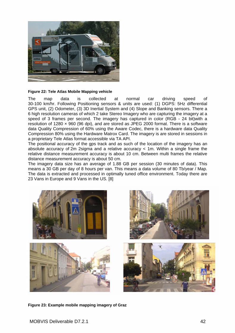
MOBVIS Deliverable D7.2.1 42
Figure 22: Tele Atlas Mobile Mapping vehicle
The map data is collected at normal car driving speed of 30-100 km/hr. Following Positioning sensors & units are used: (1) DGPS: 5Hz differential GPS unit, (2) Odometer, (3) 3D Inertial System and (4) Slope and Banking sensors. There a 6 high resolution cameras of which 2 take Stereo Imagery who are capturing the imagery at a speed of 3 frames per second. The imagery has captured in color (RGB - 24 bit)with a resolution of 1280 × 960 (96 dpi), and are stored as JPEG 2000 format. There is a software data Quality Compression of 60% using the Aware Codec, there is a hardware data Quality Compression 80% using the Hardware Matrox Card. The imagery is are stored in sessions in a proprietary Tele Atlas format accessible via TA API. The positional accuracy of the gps track and as such of the location of the imagery has an absolute accuracy of 2m 2sigma and a relative accuracy < 1m. Within a single frame the relative distance measurement accuracy is about 10 cm. Between multi frames the relative distance measurement accuracy is about 50 cm. The imagery data size has an average of 1.88 GB per session (30 minutes of data). This means a 30 GB per day of 8 hours per van. This means a data volume of 80 Tb/year / Map. The data is extracted and processed in optimally tuned office environment. Today there are 23 Vans in Europe and 9 Vans in the US. [8]
Figure 23: Example mobile mapping imagery of Graz

MOBVIS Deliverable D7.2.1 43
4.4.3.1 TELE ATLAS 3D CITY MAPS PRODUCTION PROCESS
Figure: Cost- Efficient Tele Atlas 3D Map Production Process Using Tele Atlas Mobile Mapping technology presents a cost-efficient alternative. Image sequences captured with the Tele Atlas Mobile Mapping Vehicles (Figure 1) are the solutions to produce high end 3D City Maps. The vehicles have a number of cameras, some of them stereographic and all of them are accurately geo-positioned. While driving the road network, image sequences are being captured. Thanks to an intelligent image sequence processing tool, the Tele Atlas production team can easily analyse all details and produce high end quality products. The cameras are positioned in such a way that the information needed for the production of 3D buildings is present and can be used as source information for 3D City Maps.
4.4.3.2 DIFFERENT LEVELS OF DETAIL REQUIRED Since the 3D City Maps have to support different applications for which different levels of details are required, those 3D City Maps must be generated so that they can be delivered in different levels of detail. The different levels of detail can be defined as follows: (1) the block models (2) the block models with roof type (3) the block models with roof types and generic facades (4) the block models with roof types and detailed facades for ground level and generic facades information for the rest of the façade. The requirement of offering different levels of detail, excludes the use of geo-coded VRML or 3DS objects.

MOBVIS Deliverable D7.2.1 44
4.4.3.3 TELE ATLAS 3D GDF: COMPONENT BASED APPROACH In order to allow the storage of 3D information, a proposal to extend the GDF (Geographic Data Files) model, which is the standard for the definition and exchange of digital road maps, has been made by Tele Atlas. As a result the 3D City Map is produced and stored on top of the digital roadmap database. This completely excludes mismatching between roads and building outlines. This 3D GDF extension is proposed by Tele Atlas to the ISO and accepted for standardization. The building area receives an absolute or relative altitude. Depending on the height of the building, this information can be retrieved from the Mobile Mapping image sequences. In case the buildings are too high other methods and processes are used to generate the building altitude. In addition the building area gets the roof type attribute, pointing to the roof type library. These roof types could be stored as 3DS or VRML objects. Additional to this, the 3D GDF extension is built in such a way that each building façade is split up in components: window types, door types, sequence and placement. This information can be stored per storey. Depending on the level of detail to achieve, the library can be extended.
Figure 24: Visualization sequence of façade components
Experience has shown that complex shopping streets with typical windows and inscriptions can hardly be produced using the window and door type libraries. As a result an extra library of façade components, being processed digital terrestrial photos has to be generated. This is only required for the part of the façades representing the ground level. The rest of the façade can still be produced only using the window, door and roof type libraries.
4.4.3.4 LIBRARY GENERATION OF BUILDING COMPONENTS The libraries are generated from the image sequences of the Mobile Mapping Vehicles, using semi-automatic object recognition tools. Afterwards a production object recognition tool
compares the image sequences with the generated libraries. This object recognition tool has the challenging task to propose a set of components per image sequence. It is up to the cartographer to accept or reject the computer vision proposal or manually attribute the components per building façade storey. Figure 25: Generic 3D City Model and component based approach 3D City Model.
The result is an enhanced digital map, containing the component attributes per building façade. The complete component based approach 3D GDF extension allows the production of different levels of detail, which results in products with according level of detail.

MOBVIS Deliverable D7.2.1 45
4.4.2 TECHNOLOGY TO PRODUCE 3D LANDMARKS 3D landmarks are generated by Tele Atlas partner (GTA) [9]. They first capture geo-referenced photographs, then generate geometry with photogrammetric software. They texture the geometrical object with digital photographs and fit the geographic position to Tele Atlas data base.
Figure 26: Production 3D landmark
The 3D landmark is stored in an external directory. The 2D Building footprint of the corresponding 3D landmark is stored in the Tele Atlas DB. Also the Point of interest of the 3D Landmark is stored in the 2D Building footprint in the standard Tele Atlas database. Those 3D landmarks may be stored as geo-coded 3DS or VRML objects. In addition to the coordinates present in the 3D geo-coded object and the map database, the 3D landmark is linked to the map database by means of a topological pointer. This excludes mismatching between the building footprints of the 3D landmarks and the roads and other 3D data in the digital map. The 3D landmarks products are offered as WGS84 geocoded VRML, WGS84 geocoded compressed VRML, WGS84 geocoded Alias Wavefront (reference in gaming industrie, ASCII format) and kml.
4.4.3 TECHNOLOGY TO PRODUCE TELE ATLAS TERRAIN MODELS Currently 3 processes are evaluated to produce in a cost efficient way Tele Atlas Terrain Models for the city areas.
1) Using the 2D city maps and overlay them with the SRTM data. Cut out the corresponding parts of the Tele Atlas elevation models and change the height value of this area with a height value of a surrounding cell value => bad results so far. Main reason is that the size of a footprint is much more smaller then the size of a Tele Atlas elevation model pixel size.
2) Produce Tele Atlas terrain models for cities based on aerial stereo imagery. 3) Tele Atlas is co-operating with various commercial parties and universities to test
algorithms for the removal of building height information and other non – terrain related height information out of SRTM data.

MOBVIS Deliverable D7.2.1 46
4.4.4 DATA VOLUMES Data volumes certainly count for on-board navigation purposes, but become crucial for off-board navigation purposes. The volume of standard VRML or 3DS 3D models is high, but can enormously be reduced using compression technology. Still, those compressions can not beat the data volumes of 3D City Models produced using the 3D GDF component based approach extension. To give some indicative data volume ranges: the standard non compressed Tele Atlas City Map (containing boundaries of all buildings and outlines of footpaths) measures about 200 kb/km2. The 3D block models produced with the 3D GDF component based approach extension measures about 275 kb/km2. For the production of 3D block models with roof types and generic façade information a 330kb for the complete library has to be added. Those libraries can be used for a complete country. If it is indeed required to enhance the level of detail on junction level, an extra of 10kb per processed façade picture of the ground level has to be added. An extra of about 100 kb per km2 has to be added in order to link the map data to those libraries. The geo-coded 3D landmarks have a data volume between 70 to 150 kb per 3D landmark.
4.5 IMPLEMENTATION CONCEPTS WITHIN THE MOBVIS SYSTEM ARCHITECTURE (JRS)
5. SUMMARY AND OUTLOOK
An extensive geo-information data base will build up within the project based on existing map content and also especially generated geo-information focusing the specific requirements of the defined scenarios which are defined in work package 2. The data access for the basic map content and also the map integration platform where realised as OGC-conform solution. Therefore, the data access within the project partners and also to potential external partners is standardised and allows an easy data exchange for developments during the project as well as in future developments. A detailed design of the databases and the used data structure to store geo-data used by all MOBVIS modules will be described in deliverable D5.1.2. (“Geo-information database for sample urban scenarios and report”). First proto-demonstrator implementations regarding this task are described in deliverable D7.2.1.

MOBVIS Deliverable D7.2.1 47
6. ANNEX 1: WFS OPERATIONS: DETAILED DESCRIPTIONS
6.1 GETCAPABILITIES OPERATION A web feature service must have the ability to describe its capabilities. The <GetCapabilities> element is used to request a capabilities document from a web feature service. It is defined by the following XML Schema fragment:
The capabilities document is composed of four main sections: Service section The service section provides information about the service itself. Capabilities Section The capability section specifies the list of requests that the WFS can handle. Two classes of web feature services, based on the capabilities they support, are defined: Basic WFS, Transaction WFS. FeatureType List This section defines the lists of feature types (and operations on each feature type) that are available from a web feature service. Additional information, such as SRS, about each feature type is also provided. Filter Capabilities Section The schema of the Filter Capabilities Section is defined in the Filter Encoding Implementation Specification. This is an optional section. If it exists, then the WFS should support the operations advertised therein. If the Filter Capabilities Section is not defined, then the client should assume that the server only supports the minimum default set of filter operators as defined in the Filter Encoding Implementation Specification.
6.2 DESCRIBEFEATURETYPE OPERATION The task of the DescribeFeatureType operation is to generate a schema description of feature types serviced by a WFS implementation. The schema descriptions define how a WFS implementation expects feature instances to be encoded on input and how feature instances will be generated on output. The following XML Schema fragment defines the XML encoding of a DescribeFeatureType request:
<xsd:elementname="DescribeFeatureType"type="wfs:DescribeFeatureTypeType"/> <xsd:complexTypename="DescribeFeatureTypeType"> <xsd:sequence> <xsd:elementname="TypeName"type="xsd:QName"minOccurs="0"maxOccurs="unbounded"/> </xsd:sequence> <xsd:attributename="version"type="xsd:string"use="required"fixed="1.0.0"/> <xsd:attributename="service"type="xsd:string"use="required"fixed="WFS"/> <xsd:attributename="outputFormat"type="xsd:string"use="optional"default="XMLSCHEMA"/> </xsd:complexType>
<xsd:elementname="GetCapabilities"type="wfs:GetCapabilitiesType"/> <xsd:complexTypename="GetCapabilitiesType"> <xsd:attributename="version"type="xsd:string"use="optional"/> <xsd:attributename="service"type="xsd:string"use="required"fixed="WFS"/> </xsd:complexType>

MOBVIS Deliverable D7.2.1 48
In response to a DescribeFeatureType request, where the value of the outputFormat attribute has been set to XMLSCHEMA, a WFS implementation must be able to present an XML Schema document that is a valid GML application schema and defines the schema of the feature types listed in the request. The document(s) presented by the DescribeFeatureType request may be used to validate feature instances generated by the WFS in the form of feature collections on output or feature instances specified as input for transaction operations.
6.3 GETFEATURE OPERATION The GetFeature operation allows retrieval of features from a web feature service. A GetFeature request is processed by a WFS, and an XML document containing the result set, is returned to the client. The XML encoding of a GetFeature request is defined by the following XML Schema fragment:
The <GetFeature> element contains one or more <Query> elements, each of which in turn contain the description of a query. The <Query> element defines which feature type to query, what properties to retrieve and what constraints (spatial and non-spatial) to apply to those properties. The results of all queries contained in a GetFeature request are concatenated to produce the result set. The <Filter> element, contained within the <Query> element, can be used to define constraints on a query. Both spatial and/or non-spatial constraints can be specified as described in the Filter Encoding Specification. If no <Filter> element is contained within the <Query> element, then the query is unconstrained and all feature instances should be retrieved. The root element of a filter expression, <Filter>, is defined by the following XML Schema fragment:
<xsd:elementname="GetFeature"type="wfs:GetFeatureType"/><xsd:complexTypename="GetFeatureType"> <xsd:sequence> <xsd:elementref="wfs:Query"maxOccurs="unbounded"/> </xsd:sequence> <xsd:attributename="version"type="xsd:string"use="required"fixed="1.0.0"/> <xsd:attributename="service"type="xsd:string"use="required"fixed="WFS"/> <xsd:attributename="handle"type="xsd:string"use="optional"/> <xsd:attributename="outputFormat"type="xsd:string"use="optional"default="GML2"/> </xsd:attribute> <xsd:attributename="maxFeatures"type="xsd:positiveInteger"use="optional"/> </xsd:complexType> <xsd:elementname="Query"type="wfs:QueryType"/> <xsd:complexTypename="QueryType"> <xsd:sequence> <xsd:elementref="ogc:PropertyName"minOccurs="0"maxOccurs="unbounded"/> <xsd:elementref="ogc:Filter"minOccurs="0"maxOccurs="1"/> </xsd:sequence> <xsd:attributename="handle"type="xsd:string"use="optional"/> <xsd:attributename="typeName"type="xsd:QName"use="required"/> <xsd:attributename="featureVersion"type="xsd:string"use="optional"/> </xsd:complexType>
<xsd:element name="Filter" type="ogc:FilterType"/> <xsd:complexTypename="FilterType">
<xsd:choice> <xsd:elementref="ogc:spatialOps"/> <xsd:elementref="ogc:comparisonOps"/> <xsd:elementref="ogc:logicOps"/> <xsd:elementref="ogc:FeatureId"maxOccurs="unbounded"/> </xsd:choice>
</xsd:complexType>

MOBVIS Deliverable D7.2.1 49
The following XML Schema fragment defines an example of a spatial operator, the <BBoxType> type:
The format of the response to a GetFeature request is controlled by the outputFormat attribute. The default value for the outputFormat attribute shall be GML2. This will indicate that a WFS must generate a GML document of the result set that conforms to the OGC Geography Markup Language Implementation Specification, version 2.1.1, and more specifically, the output must validate against the GML application schema generated by the DescribeFeatureType operation.
7. ANNEX 2
This Annex describes the WMS operations in detail.
7.1 GETCAPABILITIES OPERATION The GetCapabilities request returns the WMS server's service-level metadata, which is a machine-readable (and human-readable), description of the WMS service's information content and acceptable request parameters. The response to a GetCapabilities request is general information about the service itself and specific information about the available maps. This response is the "capabilities" document, which is an XML configuration file that is provided to requesting WMS clients. This XML file is the metadata about a WMS server indicating its data holdings and abilities. A server sends this information upon request as an XML document formatted according to well-defined Document Type Definition (DTD). The most critical part of the WMS Capabilities XML is the Layers and Styles it defines. This file is required by the WMS Specification and must conform to the OGC's WMS Document Type Definition. When requesting a map, a WMS client may specify the layer(s) information and associated styles, as well as the desired output format. First, however, a WMS client needs to find out what it can request from a particular WMS server (find out the WMS server's service capabilities). In order to find out what layers a WMS server supplies and what projections it supports, a WMS client makes a "Capabilities Request." Another purpose of the GetCapabilities request is to declare the GetMap services that are provided. You must be able to deliver an XML metadata file via HTTP upon receiving a request such as: http://www.opengeospatial.org/wms/process.cgi?REQUEST=GetCapabilities&VERSION=1.1.0&SERVICE=WMS This request can be broken up into URL components, as shown below:
URL Component Description http://www.opengeospatial.org/wms/process.cgi? URL Prefix of server VERSION=1.1.1& Request Version REQUEST=GetCapabilities& Request Name
<xsd:elementname="BBOX"type="ogc:BBOXType"substitutionGroup="ogc:spatialOps"/> <xsd:complexTypename="BBOXType"> <xsd:complexContent> <xsd:extensionbase="ogc:SpatialOpsType"> <xsd:sequence> <xsd:elementref="ogc:PropertyName"/> <xsd:elementref="gml:Box"/> </xsd:sequence> </xsd:extension> </xsd:complexContent> </xsd:complexType>

MOBVIS Deliverable D7.2.1 50
The URL need not be the same as that for GetMap. Therefore, you could arrange for another server to provide this functionality. You must be able to provide any GetMap service that you declare in the XML file. This file is to be returned with mime type set to "text/xml". The response to a GetCapabilities request is a Capabilities XML document (XML file as per Capabilities DTD or MIME type in case of HTTP) conforming to the Schema given in the OWS Service Metadata XML IPR, composed of four main sections depicted in Figure 9, below.
7.2 GETMAP OPERATION The GetMap request returns a map image whose geospatial and dimensional parameters are well defined. The map operation of the GetMap request is invoked by a client to get a rectangular set of pixels. These pixels contain a picture of a map covering a geographic area or a set of graphic elements that lie in a geographic area. The GetMap request allows the WMS client to specify distinct layers, the spatial reference system (SRS), the geographic area, and other parameters describing the returned map format. Upon receiving the GetMap request, a WMS server will either satisfy the request or throw an exception in accordance with the exception instructions contained in the GetMap request. When invoking a GetMap request, a WMS client can specify the information to be shown on the map: one or more "Layers", possibly the "Styles" of those Layers, what portion of the Earth is to be mapped (a "Bounding Box"), the projected or geographic coordinate reference system to be used (SRS), the desired output format, the output size (Width and Height), and background transparency and colour. The required fields as well as the optional fields of a GetMap request are presented in the table below: Request Parameter Required/
Optional Description
VERSION=version REQUEST=GetMap LAYERS=layer_list STYLES=style_list SRS=namespace:identifier BBOX=minx,miny,maxx,maxy WIDTH=output_width HEIGHT=output_height FORMAT=output_format TRANSPARENT=TRUE/FALSE BGCOLOR=color_value EXCEPTIONS=exception_format TIME=time ELEVATION=elevation Other sample dimension(s) Vendor-specific parameters
R R R R R R R R R O O O O O O O
Request version Request name Comma-separated list of one or more map layers. Optional is SLD parameter is present Comma-separated list of one rendering style per requested layer. Optional if SLD parameter is present Spatial Reference System Bounding box corners (lower left, upper right) in SRS units Width in pixels of map picture Height in pixels of map picture Output format of map Background transparency of map (default-FALSE) Hexadecimal red-green-blue color value for the background color (default=0xFFFFFF). The format in which exceptions are to be reported by the WMS (default=SE_XML) Time value of layer desired Elevation of layer desired Value of other dimensions as appropriate Optional experimental parameters
The following parameters are used only with Web Map Services that support the Styled Layer Descriptor specification.
MOBVIS Deliverable D7.2.1 51
SLD=styled-layer_descriptor_URL WFS=web_feature_service_URL
O O
URL of Styled Layer Descriptor (as defined in SLD Specification). URL of Web Feature Service providing features to be symbolized using SLD
Table 4: GetMap Request fields
The output of a GetMap request is a single map whose type corresponds to the FORMAT parameter in the request. In the case of HTTP, for example, if the request included FORMAT=JPEG, then the returned object must be a JPEG image with a MIME type of image/jpeg. In the case of non-picture requests (i.e., graphic elements or feature data), the parameters WIDTH, HEIGHT, TRANSPARENT and BGCOLOR are not relevant and may be omitted. WIDTH and HEIGHT are mandatory when the output format is an image. GetMap returns an image as specified in the format parameter of the request (GIF, JPEG, PNG). A GetMap request returns nothing with invalid HTTP requests or by access violations. A GetMap response returns an XML structure containing error information if the WMS server detected an error. The WMS server must be able to deliver a map via HTTP upon receiving a WMS client request such as the following:
https://highway.teleatlas.com:8891/geoserver/wms?request=GetMap&width=500&height=500&format=image/gif&bbox=15.4,47.02,15.5,47.09&layers=ta:MN_NW,ta:MN_SM,ta:MN_PI&styles=MN_NW,MN_SM,MN_PI&BGCOLOR=0xF0F0D0
As a reply, the map in Figure 17 is provided.

MOBVIS Deliverable D7.2.1 52
Figure 27: Sample map reply (Graz)
7.3 GETFEATUREINFO OPERATION The GetFeatureInfo request returns information about particular features shown on a map. If a WMS server supports this operation, its maps are said to be "queryable," and a WMS client can request information about features on a map by adding to the map URL additional parameters specifying a location (as an X, Y offset from the upper left corner) and the number of nearby features about which to return information. The GetFeatureInfo operation is designed to provide WMS clients with information about a feature in a map image returned by a previous GetMap request. In other words, the map is identified by including all the information contained in the GetMap request. If a previous GetMap request is not repeated correctly in the GetFeatureInfo request, the results are undefined and will cause an exception. GetFeatureInfo request embeds the bulk of GetMap request, adding parameters to define which layer to query. The WMS server can return a text/HTML/XML page, an Image or even a Word document in response to GetFeatureInfo request. The response may even contain attribute information, or the selected feature(s) in GML format. The use case for GetFeatureInfo is that a user sees the response of a GetMap request and chooses a point on that map for which to obtain more information. The basic operation provides the ability for a client to specify which pixel is being asked about, which layer(s) should be investigated, and what format the information should be returned in. The actual semantics of how a WMS server decides what to return more information about, or what exactly to return, is left up to the WMS provider.

MOBVIS Deliverable D7.2.1 53
8. ANNEX 3: SAMPLE OF OLS GEOCODING
Annex 3 contains a sample of OLS geocoding request using the schema above. <?xml version="1.0" encoding="UTF-8"?> <GeocodeRequest xmlns="http://www.opengis.net/xls" xmlns:xsi="http://www.w3.org/2001/XMLSchema-instance" xmlns:gml="http://www.opengis.net/gml" xsi:schemaLocation="http://www.opengis.net/xls http://schemas.opengis.net/ols/1.1.0/LocationUtilityService.xsd"> <Address countryCode="IT"> <StreetAddress> <Building number="732" buildingName="Cottolengo Hospital"/> <Street typeSuffix="ST">Cottolengo Street</Street> </StreetAddress> <Place type="Municipality">Turin</Place> <PostalCode>10152</PostalCode> </Address> </GeocodeRequest> As response, the OLS service would send the following XML file back: <?xml version="1.0" encoding="UTF-8"?> <GeocodeResponse xmlns="http://www.opengis.net/xls" xmlns:xsi="http://www.w3.org/2001/XMLSchema-instance" xmlns:gml="http://www.opengis.net/gml" xsi:schemaLocation="http://www.opengis.net/xls http://schemas.opengis.net/ols/1.1.0/XLS.xsd"> <GeocodeResponseList numberOfGeocodedAddresses="1"> <GeocodedAddress> <gml:Point> <gml:pos dimension="2">45.079 7.681</gml:pos> </gml:Point> <Address countryCode="IT"> <StreetAddress> <Building number="732" buildingName=""/> <Street directionalPrefix="" typePrefix="ST" officialName="COTTOLENGO" typeSuffix="" directionalSuffix="">COTTOLENGO ST</Street> </StreetAddress> <Place type="Municipality">TURIN</Place> <Place type="MunicipalitySubdivision"></Place> <PostalCode>10152</PostalCode> </Address> <GeocodeMatchCode matchType="1" accuracy="0.0"/> </GeocodedAddress> </GeocodeResponseList> </GeocodeResponse>

MOBVIS Deliverable D7.2.1 54
9. REFERENCES
[1] International Standardisation Organisation: ISO14825:2004, Intelligent Transport Systems-Geographic Data Files-Overall Data Specification (GDF4.0), 2004-02-15
[2] Open Geospatial Consortium Inc.: Geographic Markup Language, Version 2.1.2, 2003, http://schemas.opengis.net/gml/2.1.2
[3] Beech, David, Maloney, Murry, Mendelson, Noah, Thompson, Harry S.: “XML SchemaPart 1: Structures”, W3C Recommendation, May 2001, http://www.w3c.org/TR/xmlschema-1
[4] Open Geospatial Consortium Inc.: Web Feature Service Implementation Specification, Version 1.0.0, 19-September-2002, Reference number: OGC 02-058.
[5] Open Geospatial Consortium Inc.: Web Map Service, Version 1.3, 2004-08-02, Reference number: OGC 04-024.
[6] Open Geospatial Consortium Inc.: OpenGIS Web Map Service Cookbook, Version 1.0.2, November 4, 2004, Reference number: OGC 03-050r1.
[7] Open Geospatial Consortium Inc: OpenGIS Location Services (OpenLS): Core Services [Parts 1-5] (OLS Core), Version 1.0, reference 03-006r3, 2004-01-16.
[8] T’ Siobbel, Stephen: Mobile Digital Mapping: Field data collection Matters!, ITS Nagoya 2004 [9] GTA: http://www.gta-geo.com [10] Vande Velde, Linde: Navigation in 3D Enhanced map display for car navigation and LBS, ITS Nagoya 2004 [11] Vande Velde, Linde: Navigate by Maps for Multi-Modal Transport, ITS Madrid 2003