Embed Size (px)
Citation preview
•
The International Journal of Analytical and Experimental Modal Analysis v 7 n 4 p 227-241 Oct 1992
by H. M. Kim, McDonnell Douglas Space Systems Company and R. R. Craig, Jr., University of Texas at Austin
ABSTRACT This paper demonstrates a new system identification approach of using Lanczos coordinates in place of modal
coordinates. Identified experimental Lanczos vectors can be directly used in many structural dynamics analysis applications. A multi-input, multi-output frequency-domain technique was used to extract system matrices and an unsymmetric block Lanczos algorithm was used to reduce the order of the experimental model. A cantilever beam example showed promising results, indicating that a new system identification approach using Lanczos coordinates is worthy of further study.
[A J,[.81 [C]
c [D] [E]
[F] {fr l
VJ (/} [/] s
[K] [M] {p}
first-order system matrices
damping matrix complex space force distribution matrix =[F]-T =[[Yd . . . [Yr]], left Lanczos matrix =[[X1] • • • [Xr]], right Lanczos matrix force vector for the first -order system Fourier transfonn force vector identity matrix
• •
tmagtnary space stiffness matrix mass matrix excitation vector
9\ real space (9\)n x m
....
[T] {x}
n x m (real) matrix block tridiagonal matrix displacement vector
Greek { y} a set of reduced coordinates
[ 'V c] contracting transformation matrix
[ 'V R] reconstructing transfonnation matrix ro circular frequency
[ ]T matrix transpose [ r1 tnatrix inverse [ rT =(( JTl l
Dr. Hyoung M. Kim, Staff Engineer, Space Station Division, McDonnell Douglas Space Systems Company, Houston, Texas 77062. Prof. Roy R. Craig.Jr. (SEM member),JohnJ. McKetta Energy Professor, ASE-EM Department, The University ofTexas at Austin, Au.�tin, Texas 78712.
An earlier version of this paper was presented at the 32nd AIAA SDM Conference, Baltimore, MD, Apri/199/.
Final manuscript received: Apri/25, 1992
227

. ·
.: . · �.:·
In conventional modal analyses, natural frequencies, damping factors, and mode shapes of structures are identified from the experimental data [ 1]. These identified modal parameters have been used to: construct the experimental model, verify the mathematical model, and predict structural responses. Widely used system identification algorithms include: the damped complex exponential response method [2], the forced nonnal mode excitation method [3], the frequency response function method [4], the autoregressive-moving-average (ARMA) method [5], the Ibrahim time domain (lTD) method [6], the
simultaneous frequency domain (SFD) method [7], the polyreference method [8], and the eigensystem realization algorithm (ERA) [9].
Lanczos methods have been developed for finding some or all of the eigenvalues and eigenvectors of a large symmetric sparse matrix [10, 11]. However, cancellation and roundoff errors can render the
Lanczos algorithm unstable due to the loss of orthogonality among the Lanczos vectors. Since this loss of
orthogonality can be improved [12, 13], in the past few years, there has been a renewed interest in developing eigensolvers and dynamic response solvers based on Lanczos vectors [ 14, 15]. For dynamic analyses, an unsymmetric block Lanczos algorithm may be employed to: handle matrices with repeated (or closely-spaced) eigenvalues, pennit dynamic response analyses with multiple simultaneously applied loads, and/or accommodate unsymmetric damping matrices [16, 17]. Lanczos vectors may also be used to develop reduced-order structural models for component mode synthesis and control applications [18].
This paper describes how unsymmetric block Lanczos vectors can be employed for the system identification of large structures having arbitrary damping and closely-spaced frequencies [ 19]. System matrices were estimated using a multi-input, multi-output modal parameter estimation algorithm based on excitation and response spectra [20]. The order of the identified experimental model was reduced using unsymmetric block Lanczos vectors for further applications. Simulated modal testing of a unifonn cantilever beam was employed to evaluate the new system identification approach. Responses from analytical and reduced experimental models due to external step forces showed little differences, which indicated that the reduced-order Lanczos model was a good experimental model. In addition, sensor location selection and efficiency of Lanczos eigensolution for large structural problems were briefly discussed .
. . •' . . .· :.
.·
For general linear, time-invariant dynamic systems, it is assumed that there exists a discrete analytical model
[M]{x(t)}+[C]{x(t)}+[K]{x(t)} = {/(t)} (1)
where [M], [C], and [K] e �NxN are, respectively, the mass, damping, and stiffness matrices, {x(t)} e 9\Nxi is the displacement vector, {f(t)} E 9\Nxl is the force vector, and N is the number of physical degrees of freedom.
When dealing with dynamic systems having arbitrary linear damping, it is convenient to introduce a state vector formulation
where
228 October 1992
A X(t) + iJ {x(t)} = ft(t) (2)

• . ' ' "
; ,- _ _ _ _
' ' . . . · . .. ' . . . ' . . - ,' · -. , ' • . --·- ·-
. - . \
· · - � ;--· o - � · ·
In conventional modal analyses, natural frequencies, damping factors, and mode shapes of structures
are identified from the experimental data [1] . These identified modal parameters have been used to:
construct the experimental model, verify the mathematical model, and predict structural responses. Widely
used system identification algorithms include: the damped complex exponential response method [2] , the
forced normal mode excitation method [3], the frequency response function method [4] , the auto
regressive-moving-average (ARMA) method [5] , the Ibrahim time domain (lTD) method [6], the
simultaneous frequency domain ( SFD) method [7], the polyreference method [8], and the eigensystem
realization algorithm (ERA) [9] . Lanczos methods have been developed for finding some or all of the eigenvalues and eigenvectors of
a large symmetric sparse matrix [10, 11] . However, cancellation and roundoff errors can render the
Lanczos algorithm unstable due to the loss of orthogonality among the Lanczos vectors. Since this loss of
orthogonality can be improved [12, 13] , in the past few years, there has been a renewed interest in
developing eigensolvers and dynamic response solvers based on Lanczos vectors [14, 15]. For dynamic
analyses, an unsymmetric block Lanczos algorithm may be employed to: handle matrices with repeated
(or closely-spaced) eigenvalues, permit dynamic response analyses with multiple simultaneously applied
loads, and/or accommodate unsymmetric damping matrices [ 16, 17] . Lanczos vectors may also be used
to develop reduced-order structural models for component mode synthesis and control applications [18]. This paper describes how unsymmetric block Lanczos vectors can be employed for the system
identification of large structures having arbitrary damping and closely-spaced frequencies [ 19]. System
matrices were estimated using a multi-input, multi -output modal parameter estimation algorithm based on
excitation and response spectra [20] . The order of the identified experimental model was reduced using
unsymmetric block Lanczos vectors for further applications. Simulated modal testing of a uniform
cantilever beam was employed to evaluate the new system identification approach. Responses from
analytical and reduced experimental models due to external step forces showed little differences, which
indicated that the reduced-order Lanczos model was a good experimental model. In addition, sensor
location selection and efficiency of Lanczos eigensolution for large structural problems were briefly
discussed.
For general linear, time-invariant dynamic systems, it is assumed that there exists a discrete analytical
model
[ M]{ x(t)} + [ c]{ x(t)} + [ K]{ x(t)} = {J(t)} (1)
where [M], [C] , and [K] E ')\NxN are, respectively, the mass, damping, and stiffness matrices, {x(t)} E 9\Nxl is the displacement vector, {/(t)} E 9\Nxl is the force vector, and N is the number of physical degrees of
freedom.
When dealing with dynamic systems having arbitrary linear damping, it is convenient to introduce a
state vector formulation
where
228 October 1992
(2)
I ' •
• i l l l, • ' ' I I l '
I
j 1. ' ' • •
1 l ' ' .1 '
•
• i;
• •
-
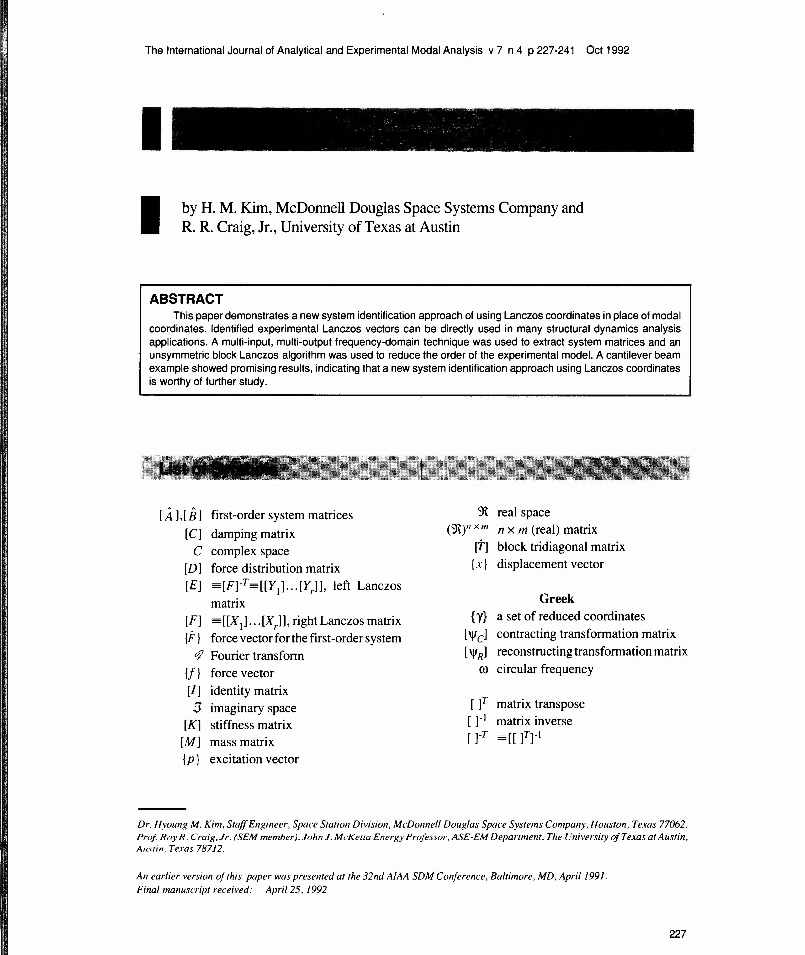
This algorithm results in a block tridiagonal matrix
0
(F]-1[A][F] =
"'
T • • •
--
• • •
0 • • [ t}r-l ]T
where
( B,._t]
[ F] = [XI] ... [ xr] ' [X;] E 9\nxp [F]-T =[EJ=[[r.] ... [Y,.]], [Yf]e9\nxp
[M;] E 9tpxp
[ B; ], [ (};] e 9\ px P and upper - triangular matrices r : number of blocks p : size of blocks
(M,.]
(7)
(8)
The vectors comprising the [Xj]'s will be referred to as right Lanczos vectors, while the [f)'s will be referred to as left Lanczos vectors. [£] and [F) will be referred to as left and right Lanczos matrices, respectively. Lanczos vectors (and matrices) will be always real contrary to eigenvectors as long as the system matrix [A] in Eq. (6) is real. It is noted that the block-tridiagonal matrix [T] is not unique, but depends on the starting-vector matrices, [X 1] and [Y 1]. Further algorithm development, including computational enhancement, can be found in Ref. [ 17].
(b) Starting Vectors
The block tridiagonal matrix [T] is not unique, but depends on the starting vectors (actually the matrices), [X.J and [Y.J. In general, the starting-vector matrices [X.J and [Y1] may be chosen arbitrarily with [X 1]7[Y1] = [/].When the external force is of the form given by Eq. (4), the starting vectors can be chosen in the direction of the static displacements, that is, appropriate starting vectors for use with Eq. (2) would be
(OJ -- K-1 [D] (9)
Then [Y1] can be found by choosing a [Y1] which satisfies [X1]T[f.J = [/],with [Y.J being detennined by using a generalized matrix inversion. This choice gives the Lanczos vectors the important advantage that they automatically include the static displacement and avoid any possible need for a static correction.
(c) Model Order Reduction
In analytical dynamics, the mode-superposition version of the Rayleigh-Ritz method is frequently emp\oyed for model order-reduction, i.e., { X(t)} is approximated by
230 October 1992
(10)
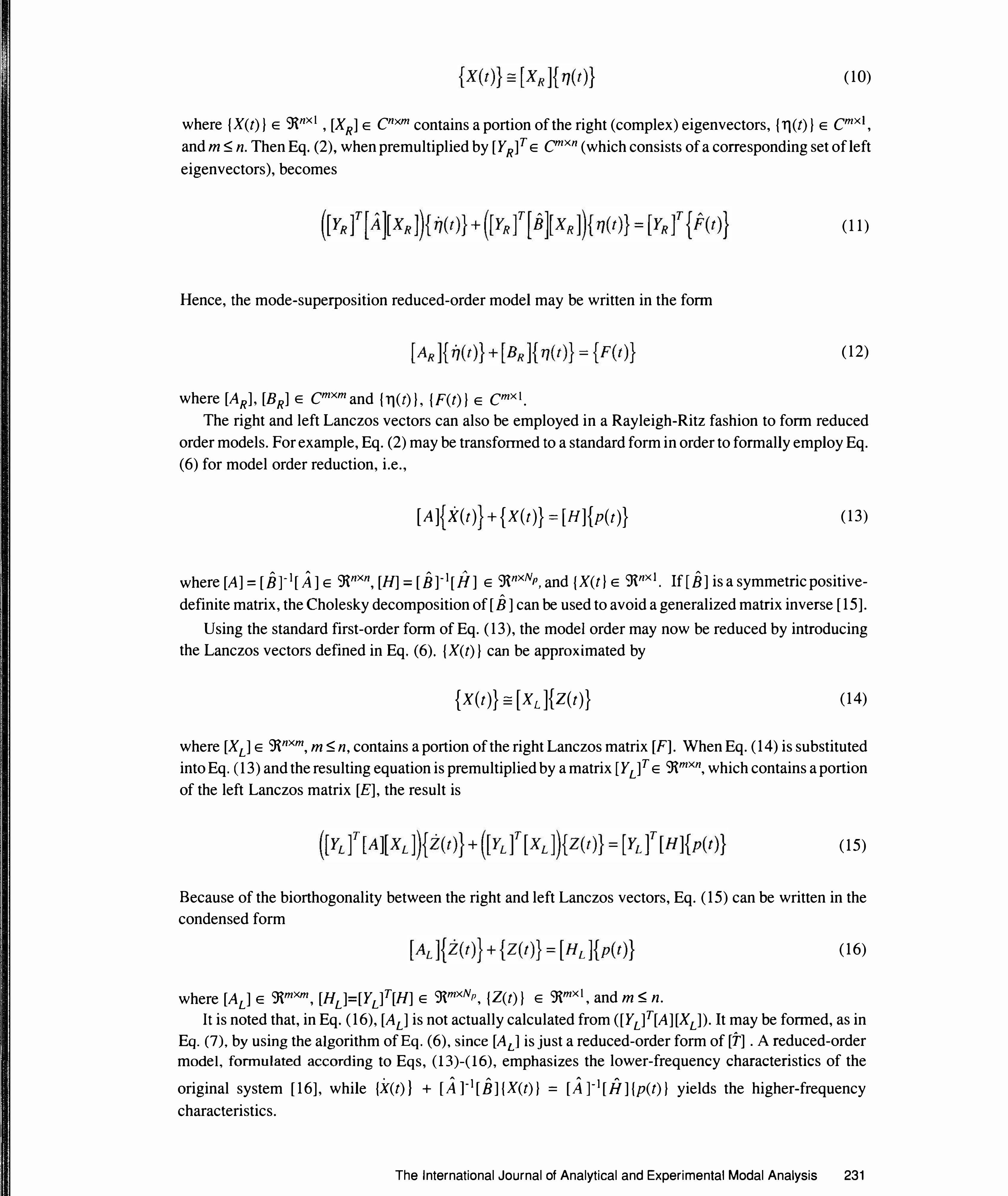
where {X(t)} E 9tnxl , [XR] E cnxm contains a portion of the right (complex) eigenvectors, {Tl(l)} E cmxl, and m � n. Then Eq. (2), when premultiplied by [YR]T e cmxn (which consists of a corresponding set of left eigenvectors), becomes
Hence, the mode-superposition reduced-order model may be written in the fonn
where [AR], [BR] E cmxm and {11(1)}, {F(t)} E cmxl .
(11)
(12)
The right and left Lanczos vectors can also be employed in a Rayleigh-Ritz fashion to fonn reduced order models. For example, Eq. (2) may be transfonned to a standard form in order to formally employ Eq. (6) for model order reduction, i.e.,
[A] X(t) +{X(t)}=[H]{p(t)} (13)
where [A]= [Br1 [A] e 9tnxn, [H] = [B]-1 [H] e 9\nxNp, and {X(t} e 9\nxt. If (B] is a symmetric positive-"
definite matrix, the Cholesky decomposition of [ B] can be used to avoid a generalized matrix inverse [ 15]. Using the standard first-order fonn of Eq. (13), the model order may now be reduced by introducing
the Lanczos vectors defined in Eq. (6). {X(t)} can be approximated by
{X(t)}:: (XL){Z(t)} (14)
where [XL] e 9tnxm, m � n, contains a portion of the rightLanczos matrix [F]. When Eq. (14) is substituted into Eq. ( 13) and the resulting equation is premultiplied by a matrix ( Y L]T e 9tmxn, which contains a portion of the left Lanczos matrix [E], the result is
(15)
Because of the biorthogonality between the right and left Lanczos vectors, Eq. ( 15) can be written in the condensed form
where [AL] e 9tmxm, [HL]=[YL]T[H] e 9\mxNp, {Z(t)} e 9tmxl , and m $; n.
(16)
It is noted that, in Eq. (16), [AL] is not actually calculated from ([YL]T[A][XL]). It may be fonned, as in Eq. (7), by using the algorithm of Eq. (6), since [AL] is just a reduced-order form of [T] . A reduced-order model, fonnulated according to Eqs, ( 13)-( 16), emphasizes the lower-frequency characteristics of the original system [16], while {X(t)} + [A l1[B] {X(t)} = [A l1[i/] {p(t)} yields the higher-frequency characteristics.
The International Journal of Analytical and Experimental Modal Analysis 231
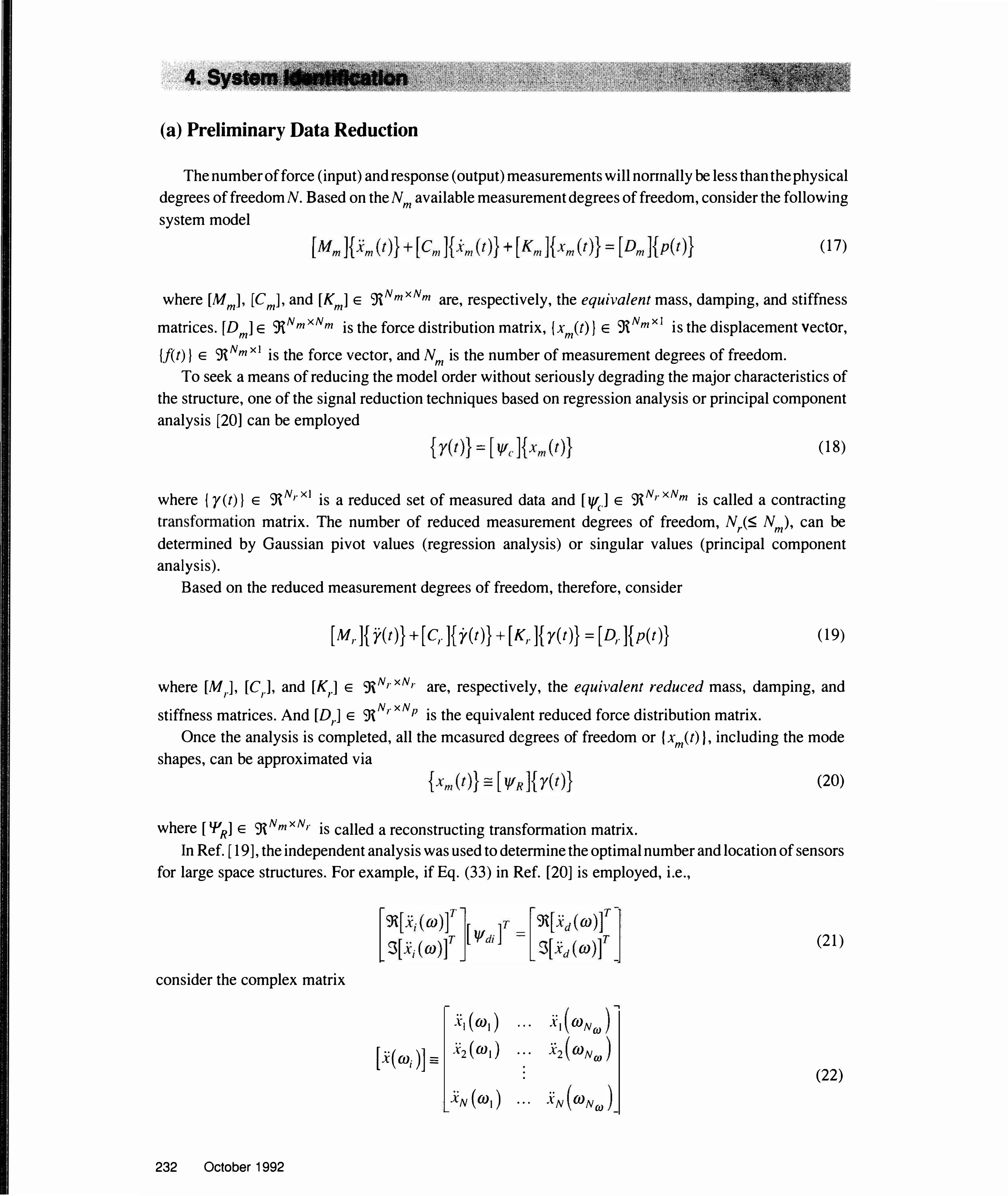
(a) Preliminary Data Reduction
The number of force (input) and response (output) measurements will nortnally be less than the physical degrees of freedom N. Based on the N m available measurement degrees of freedom, consider the following system model
(17)
where [Mm], [Cm], and [Km] e 9iNm xNm are, respectively, the equivalent mass, damping, and stiffness
matrices. [D m1 e '3iNm xNm is the force distribution matrix, {xm(t)} e 9tNm xi is the displacement vector,
{f(t)} e 9\N m xi is the force vector, and N m is the number of measurement degrees of freedom. To seek a means of reducing the model order without seriously degrading the major characteristics of
the structure, one of the signal reduction techniques based on regression analysis or principal component analysis [20] can be employed
(18)
where { y(t)} e 9\Nr xt is a reduced set of measured data and [1/'c.] e 9\Nr xNm is called a contracting transformation matrix. The number of reduced measurement degrees of freedom, Nr(-5: N m), can be determined by Gaussian pivot values (regression analysis) or singular values (principal component analysis).
Based on the reduced measurement degrees of freedom, therefore, consider
[ Mr ]{ ji( t)} + [ C,. ]{ y( t)} + ( Kr ]{ y( t)} = [ D,. ]{ p( t)} (19)
where [Mr], [Cr], and [Kr] e ')\Nr xN,. are, respectively, the equivalent reduced mass, damping, and
stiffness matrices. And [Dr] e 9\N,. xN P is the equivalent reduced force distribution matrix. Once the analysis is completed, all the measured degrees of freedom or { xm(t) ), including the mode
shapes, can be approximated via
where [ 'PR] e 9\Nm xN,. is called a reconstructing transformation matrix.
(20)
In Ref. [ 19], the independent analysis was used to determine the optimal number and location of sensors for large space structures. For example, if Eq. (33) in Ref. [20] is employed, i.e.,
consider the complex matrix
232 October 1992
[ x( m; )] =
.XI ( ml ) x2 ( m• )
.XN ( m1 )
• • •
• • •
• • •
• • •
(21)
• •
XI mNm • • x2 mN (J)
(22) • •
X N mNm

which will be driven to the following fonn by Gaussian elimination with row and column pivoting (full
pivoting):
X X X X X X
X X X X X
X X X X . . . etc.
X X X
X X
i (independent coordinate)
(23) d (dependent coordinate)
As a result, nearly-linearly-dependent rows are driven to the bottom dpositions shown in Eq. (23) and the
corresponding coordinates are selected as the dependent coordinate group. To find the real transformation matrices, however, the sampled spectra matrix of Eq. (22) was separated into real and imaginary parts and
processed together in the Gaussian elimination process. Gaussian pivot values indicate the importance of
each degree of freedom and can be used to select the optimal sensor locations.
(b) Parameter Estimation
To estimate the system parameters using only the acceleration data, consider a frequency-domain
reduced-order model based on Eq. (19)
[ M, ]{ ji( OJ)} + [ C,. ] .. {r( m)} + [ K,.] }OJ
{ ji( OJ)}= [Dr ]{p( OJ)} (24)
where
{r(OJ)} = o;[{r(t)}] (25)
and OJ[ ] denotes the Fourier transform. To find a unique set of system matrices, it is necessary to reduce
the number of unknown parameters, e.g., premultiplying Eq. (24) by the inverse of [M,]
{ji(OJ)}+ C ! {r(m)}+ K }OJ { ji( t)} = b { p( OJ)} (26)
where [C] = [M,]-1[C,] e 9\N,.xNr, [K] = [M,J -1LKrJ e 9\NrxN,., and [D] = [M,]-1[D,] e ':RN,xNP. If a data set [xm(OJ;)] represents a set of N m measured response spectra, i.e.,
then a reduced set of response spectra may be obtained by using the contracting transformation ["'c.]
[ ji( OJ;)] =: { ji( OJ1) }{ ji( W2 ) }· .. (28)
The International Journal of Analytical and Experimental Modal Analysis 233
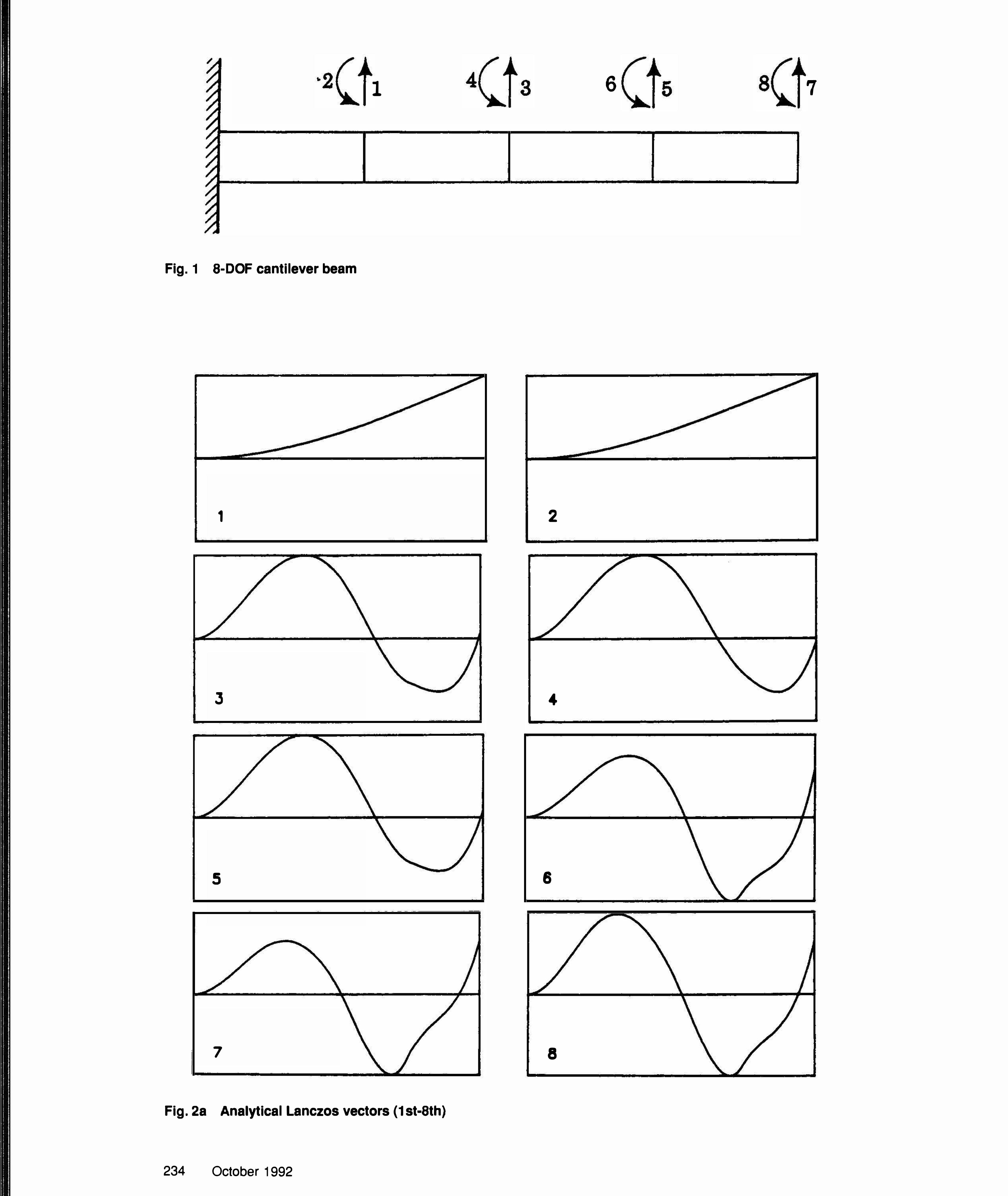
Fig. 1 8-DOF cantilever beam
1
J
5
7
1
Fig. 2a Analytical Lanczos vectors (1 st-8th)
234 October 1992
4 3 6 5 8 7
2
4
6
8
9
1 1
13
1 5
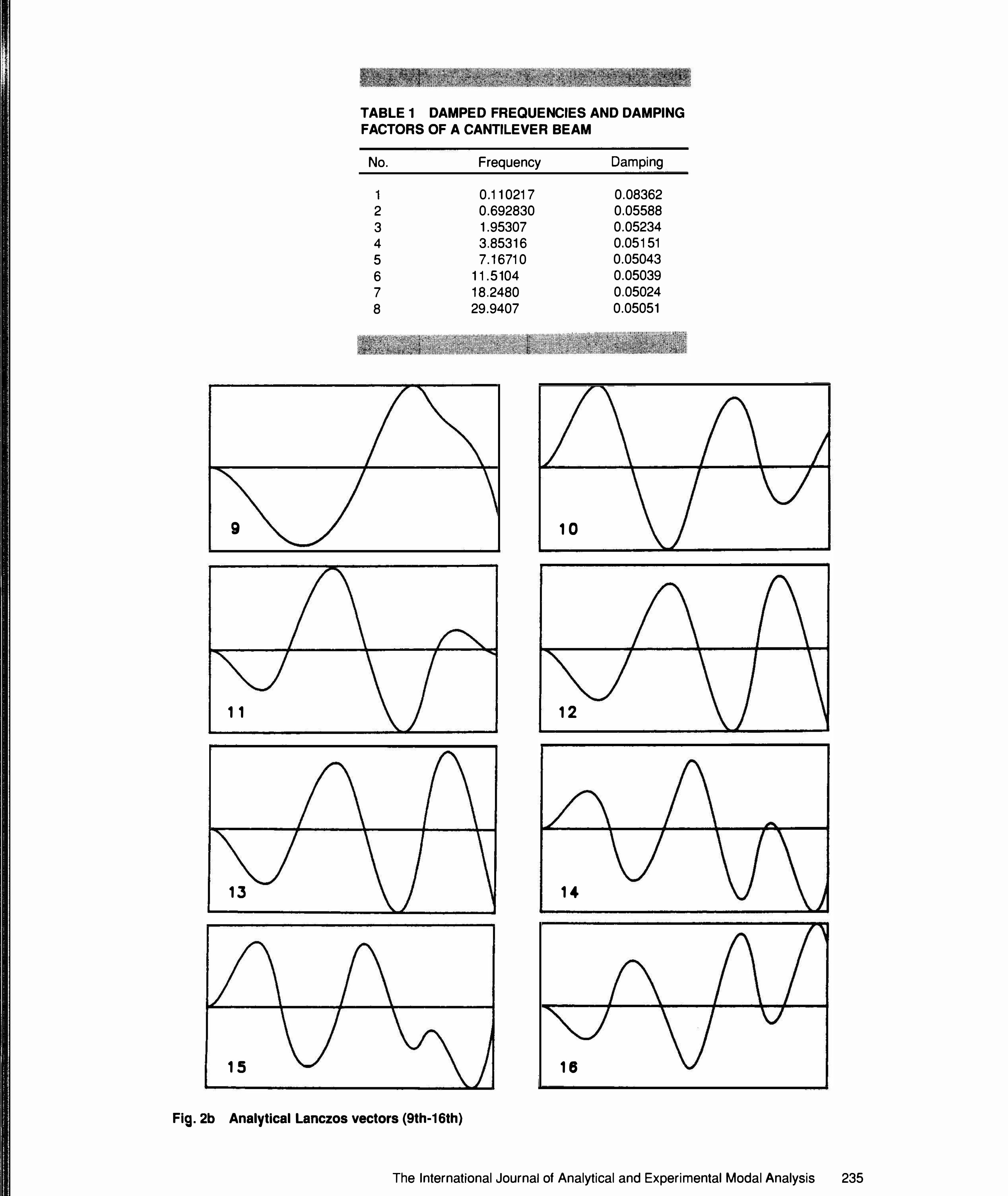
TABLE 1 DAMPED FREQUENCIES AND DAMPING FACTORS OF A CANTILEVER BEAM
No.
1 2 3 4 5 6 7 8
Frequency
0.11 0217 0.692830 1 .95307 3.8531 6 7.16710
1 1.5104 18.2480 29.9407
1 0
12
14
18
Damping
0.08362 0.05588 0.05234 0.05 151 0.05043 0.05039 0.05024 0.05051
Fig. 2b Analytical Lanczos vectors (9th-16th)
The International Journal of Analytical and Experimental Modal Analysis 235

To accommodate the condensed experimental acceleration spectra defined by Eq.(28), Eq. (26) may be expanded for N w discrete frequencies and rearranged to give
"' "' "'
C K D
1 .. ( ) -- r m. • I ]OJ I
I "
( ) 2 r OJ; -OJi
-p( (J)i)
"' "' "'
(29)
A standard least-squares problem for [ C] , [K] , and [D] may be formulated by transposing and separating the real and imaginary parts of Eq. (29).
r m. l .. ( ) • l ]Wt
r m. l .. ( ) • l
]OJ I
or, in condensed fonn
T l .. ( ) 2 r w;
-(J). l T
I .. ( ) 2 r OJi
-OJ. I
T "' T
[-p( W;) r c
[-r( W; w "' T K -T -
1-r(w;W (30) 1-p( W; )r
A T D
(31)
where [AJ is the 2N ro x (2N,. + NP) known coefficient matrix, [Bs] is the 2N w x N,. known matrix, and [Ysl is the (2Nr + N P) x N,. unknown matrix.
Now the system matrix [A] in Eq. (13) can be estimated by: solving the least-squares problem of Eq. (31) using excitation and response spectra; transfonning Eq. (26) into a time-domain model (equivalent to Eq. (1)); and changing it to a first order model (equivalent to Eq. (2)). Reference [19] discussed several least-squares algorithms in detail.
(a) Proposed System Identification Approach
Figure 1 shows an 8-DOF finite element model of a unifonn cantilever beam [ 19] which was employed to evaluate the new system identification procedure using numerical simulation. Table 1 shows the damped frequencies and damping factors of the model. This model has 5% modal damping for each mode, as well as some discrete damping at DOF = 1, 3, 5, and 7. As a result, it is necessary to use a state vector formulation. First, an analytical model ofEq. ( 1) was generated. By using special starting vectors, the analytical Lanczos vectors were generated (see Fig. 2), which will be compared with experimental Lanczos vectors. It is noted that Lanczos vectors always span the real space 9t, while eigenvectors may span the complex space C.
Response (acceleration) data were produced by numerical simulation and then transformed to response
236 October 1992
•

spectra by the fast Fourier transfonn. For simulation, the type of input was random (at DOF = 5 and 7); the sampling rate was 10.53 Hz; the cut -off frequency was 4.1 1 2 Hz; the frequency resolution was 0.02056 Hz; and the number of samples was 512. Since the order of a model is small, the preliminary data reduction step
was not employed for this example. The experimental system model was identified by solving the least-squares problem of Eq. (31 ) . The
experimental Lanczos vectors were identified from Eq. (6). It can be seen that the experimental Lanczos vectors are different from the analytical ones. This difference exists because Lanczos vectors are not
unique. However, both analytical and experimental vectors of higher-order exhibit increasingly more complex deflection shapes, i.e., vectors having a greater number of nodes [18].
The experimental reduced order model was constructed by using eight Lanczos vectors (see Fig. 3 ). To compare the analytical and reduced experimental models, responses (acceleration) due to external step forces at DOF = 5 and 7 (see Figs. 4 and 5) were generated. Figures 6 and 7 show the responses at DOF
= 5, based on the analytical model of order 16 and the reduced experimental model of order 8, respectively,
1 2
3 4
5 6
7
Fig. 3 Experimental Lanczos vectors (1st-8th)
The International Journal of Analytical and Experimental Modal Analysis 237

and Figs. 8 and 9 show the responses at DOF = 7. The approximate responses are almost the same as the exact responses, which indicate that the reduced-order Lanczos model is a good experimental model. In this new system identification approach, a numerically expensive eigenvalue problem was not involved.
(b) Sensor Location Selection
Figure 10 shows a 60-DOF simplified finite element model of the Space Station Freedom. In this example, the preliminary data reduction based on regression analysis was used to reduce the number of measurement degrees of freedom, i.e., N m of Eq. ( 17) to N, of Eq. ( 19). Random input was applied at node number 4 and acceleration responses were generated by numerical simulation.
1.0
., •
� 0.5 0
• • L&J 0
� 0.0 �
-o. s
0. 0 10.0 20.0 30.0 40.0 50.0 60:0 TIME (SEC)
Fig. 4 External Step Force at DOF = 5
r r r 1 - r- 1
+J.OE+OO
'17 +2. OE+OOI � 0 Q
+1. OE+OOL .. L&J en
� � VI +0. OE+OO� L&J
I .a:::
-1. OE+OO
0.0 10.0 20.0 JO.O 40.0 TIME (SEC)
Fig. 6 Exact response at DOF = 5
+1.5E+01
'il +1. 0£+01 t'; 0
.. L&J "' � +5. OE+OO a.. "' L&J .a:::
+0. OE+OO
I I 1 ' . I
1 ' • I ' ' -. • '
; • t "'"'1
I ! 1 '
� I • .
J 50.0 60.0
0.0 10.0 20.0 30.0 40.0 so.o 60.0 Tit.€ (SEC)
Fig. 8 Exact response at DOF = 7
238 October 1992
1. 0
,.... II
t5 0.5 c
• • L&J () � 0 0. 0 ....
-0.5
0.0 10.0 20.0 30.0 40.0 50.0 60.0 TIME (SEC)
Fig. 5 External Step Force at DOF = 7
Ill II Lt..
0 0
.. L&J Cl) z 0 a.. Cl) L&J ct:
r 1 +3. OE+OOj
I ' I
+2. OE+OOI I
+1. OE+OOr-' I • +0. OE+OO� • I I -1. OE+OOr
I I I 0.0
I
I 10.0
I I f
I .L I 20.0 30.0 40.0
TIME (SEC)
I
I 50.0
Fig. 7 Approximate response at DOF = 5
+1.5E+01
,.... II
+1.0£+01 � 0
• • L&J "' � +5. OE+OO a.. "' L&J a::
+0. OE+OO
fl j I • '
' ' , I
I
i '
� I --.1 J
60.0
0.0 10.0 20.0 JO.O 40.0 50.0 60.0 Tit.£ (SEC)
Fig. 9 Approximate response at DOF = 7

During the preliminary data reduction process of Eq. (23), a Gaussian pivot value for each degree of freedom (and corresponding coordinate) was determined. These pivot values in Fig. 11 indicated the importance of each sensor, which was used to determine the optimal number and location of sensors. Complete system identification results can be found in Ref. [ 19]
(c) Lanczos Eigensolution
To evaluate the efficiency of the Lanczos eigensolver for a large structural problem, the inverse power method and Givens method as well as the Lanczos method were tested by using MSC/NASTRAN on a Cyber 6400/6600 computer and a Cray X-MP/24 supercomputer. The test model is a 474-DOF finite element model of the Space Station Freedom first flight configuration (Fig. 12). The computed eigenvalues
were exactly the same between the methods, but the computing cost for the Lanczos method was significantly reduced, as seen in Table 2. 6
TABLE 2 COMPUTING TIME FOR EIGENSOLUTIONS I
Computer
• 0 z � 0 V) z LAJ en �
"""'
Cyber Cray Cray Cray
5.0
0.0
-5.0
<-' 0-10.0 ...J
.........
(I) L&J 3 _, 5. 0 --= > � 0 > -20. 0 ..... Q..
-25.0
0
Methods CPU Time (sec)
Inverse Power Method Inverse Power Method Givens Method Lancozos Method
SENSOR NO. •
1666.42 74.98 12.62
2.30
(NODE NO. - f) • e + DOf
31
25
50
32
S7
27
37
20
se
4S
35
21
33
31
24
28
42
22
f7
38 58
se
3
21
40 14
13 21 1 2
tS tt
44 41 53
43 t 7
a 47
Sl 48
St 40
54 52
so 34
s
30
10 20 30 40 50 NUMBER OF SENSORS
18
us 23
10
, , 12
•a
35
4
8
60
1/0 Time (sec)
625.90 35.20
0.70 1.65
1
8
9
Fig. 10 60-DOF Simplified Space Station Freedom model
Fig. 11 Gaussian pivot values for sensor location selection
Fig. 12 474-DOF Space Station Freedom model
The International Journal of Analytical and Experimental Modal Analysis 239
A new system identification approach using Lanczos coordinates has been presented. A multi-input, multi-output frequency-domain technique generated system matrices for a general linear, time-invariant dynamic system. The order of the identified dynamic system was reduced using Lanczos coordinates in place of conventional modal coordinates. Identified experimental Lanczos vectors can be used for other applications such as component mode synthesis and control analysis. A cantilever beam example showed promising resu1ts, indicating that a new system identification approach using Lanczos coordinates is worthy of further study. The sensor location selection process was demonstrated using the frequencydomain data reduction analysis. The computational efficiency of Lanczos method was compared to other conventional eigensolvers for a large structural problem.
The research summarized in this paper was conducted under Contract NASS-35338 with NASA George C. Marshall Space Flight Center and Contract NAS9-17254 with NASA Lyndon B. Johnson Space Center.
I . Ewins, D.J. Modal Testing: Theory and Practice. New York: John Wiley & Sons, Inc.; 1984. 2. Prony, R. ��Essai Experimental et Analytique sur les Lois de la Dilatabilite des Fluides Elastiques et
sur Celles de Ia Force Expansive de Ia Vapeur de 1 'Eau et de Ia Vapeur de 1 'Alkool, a Differentes Temperatures." J. de I' Ecole Polytechnique (Paris) Vol. 1, Cahier 2, Floreal et Prairial, An. III, p 24-76, 1795.
3. Lewis, R.C.; Wrisley, D.L. "A system for the excitation of pure natural modes of complex
structures." J Aeronaut Sci v 17 n 11 p 705-722 Nov 1950. 4. Stahle, C.V.,Jr.; Forlifer, W.R. "Ground vibration testing ofcomplexstructures." Flight Flutter Testing
Symposium, 1958. NASA-SP-385 p 83-90. 5. Gersch, W. "Estimation of the autoregressive parameters of a mixed autoregressive moving-average
time series." IEEE Trans Autom Control v AC-15 p 583-588 Oct 1970.
6. Ibrahim, S .R.; Mikulcik, E. C. "A method for the direct identification of vibration parameters from the free response." Shock Vib Bull, v 47 pt 4 p 183-198 Sept 1977.
7. Coppolino, R.N. "A simultaneous frequency domain technique for estimation of modal parameters from measured data." SAE Pap 811046 Oct 1981.
8. Void, H.; Rocklin, G.T. "The numerical implementation of a multi-input modal estimation method for mini-computers," Proceedings of t he 1st International Modal Analysis Conference, Orlando, FL, Nov 8-10, 1982. p 542-548
9. Juang, J.N.; Pappa, R.S. "An eigensystem realization algorithm for modal parameter identification and model reduction." J Guid Control Dyn, v 8 n 5 p 620-627 Oct 1985.
10. Lanczos, C. "An iteration method for the solution of the eigenvalue problem of linear differential and integral operators." J Res Nat/ Bur Stand (US) v 45 n 4 p 255-282 Oct 1950.
240 October 1992
1 I. Wilkinson, J.H. The Algebraic Eigenvalue Problem. Oxford: Claredon Press; 1965.
12. Paige, C.C. "Practical use of the symmetric Lanczos process with reorthogonalization." BIT
(Copenhagen) v 10 n 2 p 183-195 1970.
13. Parlett, B.N.; Scott, D.S. "The Lanczos algorithm with selective orthogonalization." Math Comp
v 33 n 145 p 217-238 1979.
14. Parlett, B.N.; Reid, J.K. "Tracking the progress of the Lanczos algorithm for large symmetric
eigenproblems." IMA J Numer Anal v 1 p 135-155 1981. 15. Smith, I.M.; Heshmati, E. E. "Short communications: use of a Lanczos algorithm in dynamic analysis
of structures." Earthquake Eng Struct Dyn v 11 n 4 p 585-588 Jul/Aug 1983. 16. Kim, H.M.; Craig, R.R., Jr. "Structural dynamics analysis using an unsymmetric block Lanczos
algorithm." Int J Numer Methods Eng v 26 p 2305-2318 1988.
17. Kim, H.M.; Craig, R.R., Jr. "Technical note; computational enhancement of an unsymmetric block Lanczos algorithm." lnt J Numer Methods Eng v 30 p 1083-1089 1990.
18. Craig, R.R., Jr.; Kim, H.M.; Su, T.J. "Some applications of Lanczos vectors in structural dynamics." Proceedings of the 6th International Modal Analysis Conference, Kissimmee, FL, Feb 1-4' 1988. v 1 p 501-506
19. Kim, H.M. System Identification for Large Space Structures. Ph.D. Dissertation, The University of
Texas at Austin, 1988. 20. Craig, R.R., Jr.; Kurdila, A.J.; Kim, H.M. "State-space formulation of multi -shaker modal analysis." I nt
J Anal Exp Modal Anal v 5 n 3 p 169-183 July 1990.
The International Journal of Analytical and Experimental Modal Analysis 241

------------------------------------------·--·-·
FORTHCOMING PAPERS
"Actuator/Sensor Placement for Modal Parameter Identification of Flexible
Structures," by T.W. Lim
"Determination of Elastic Constants of a Generally Orthotropic Plate by
Modal Analysis," by T.C. Lai and T.C. Lau
"Comparison of Some Direct Multi-Point Force Appropriation Methods,"
by K. Alexiou and J .R. Wright
"Stinger Mass Compensation, Part One: Theoretical Study," and " ... , Part
Two: Experimental Investigation,'' by X. Hu and K.G. McConnell
"Steady-State Dynamic Response of Structures with Nonlinear Hysteric
Isolators," by C.W. Wong, Y.Q. Ni and J.M. Ko
"Model Updating and Joint Identification Methods: Applications, Restrictions
and Overlap," by A.S. Nobari, D. A. Robb and D. J. Ewins
"Predicting the Frequency Response Function of a Structure When Adding
Constraints," by P. Salvini and A. Sestieri
"Modeling and Identification of Boundary Conditions In Flexible Structures,"
by H. Baruh and J.B. Boka
...


![Interpolation via Barycentric Coordinates · • Moving least squares coordinates [Manson and Schaefer, 2010] • Cubic mean value coordinates [Li and Hu, 2013] • Poisson coordinates](https://img.pdfslide.net/doc/110x75/6062738927364e51e610e629/interpolation-via-barycentric-coordinates-a-moving-least-squares-coordinates-manson.jpg)
![Convergence of Wachspress coordinates: from polygons to ...jiri/papers/14KoBa.pdf · convex polygons are Wachspress coordinates [14], mean value coordinates [4], and harmonic coordinates](https://img.pdfslide.net/doc/110x75/5f6dfe23261f61015179236e/convergence-of-wachspress-coordinates-from-polygons-to-jiripapers-convex.jpg)