Embed Size (px)
Citation preview
- 1 -
P00862Q
Modbus Adapter (Model : HCPC-H2M1C)
Installation Instruction Manual
Thank you for choosing Hisense
commercial air conditioner! Please keep this manual for future
reference after reading, please ask the dealer or service personnel of the company for the “Mapping Table” mentioned in this manual. If there’s any question, please contact the dealer or the service center of the company. This manual is exclusively for Modbus adapter
(HCPC-H2M1C).
Tips:Before installing Modbus adapter, please read the installation instruction manual carefully, and make sure you understand the information provided before carrying out related operation.
Preface·Important Safety Information ……….…….……… 1
1.0 System Constitution………………….….………….… 5
(Name of each part · Name of parts in Modbus adapter ·Modbus
Adapter Specifications)
2.1 Installation Place ….……………….…………… 10
2.2 Installation Method…………….………..……… 10
2.3 Wiring Connection Method...……….…………… 12
2.4 Slide Switch Setting Method ……….………………… 16
2.5 Power Supply Input...…………………………… 17
3.1 Configuration of Modbus adapter………..…………… 19
3.1.1 IP Address Setting ………...……..…………… 19
3.1.2 Clock Setting ………………………………... 25
3.1.3 Change LAN WEB Login Password...……… 26
3.1.4 Change Wireless WEB Login Password...…… 26
3.1.5 One Key to Clear EEPROM …………….…… 27
3.1.6 Remote Server IP Address Setting…………… 27
3.1.7 Subnet Mask Setting………………………… 28
3.1.8 Gateway IP Setting …………………………… 29
3.2 SD Card Data Storage……………….….………… 30
3.3 External Input and Output Linkage Function……… 30
3.4 Single Board Constant Speed Machine Login…..… 31
3 .5 Check MAC Address…….. .………………… 31
4.1 Modbus Code Composition and Analysis…………...…… 32
4.1.1 Modbus RTU Code Composition…………… 32
4.1.2 Modbus TCP Code Composition…………… 34
4.2 Control Bit Setting ………………………..…… 36
4.3 Filter Clear Setting……………………………… 36
4.4 Function Selection Setting……………………… 37
4.5 Wire Controller All Prohibition Setting………… 38
4.6 Wire Controller Partial Prohibition Setting……… 38
4.7 Do Not Install Wire Controller Setting …….…… 40
4.8 Three Important Function Setting in Mapping Table… 40
4.9 Outdoor Unit·Indoor Unit Connection Confirmation 40
4.10 Indoor Unit Data Monitoring ……….……… 41
4.11 Batch Processing Command Description …………42
4.12 Turn off Digital Tube Alarm Display Function ….42
Maintenance · After-sales Services ·Notes and Attentions… 43
Recommend upper computer Tool ………………………… 48
Centralized Control Area Unit Group Registration Form …… 49
Accessory List ……………………………………….. End Page
CERTIFICAT ………………………………………… End Page
After-sales Services
Operation M
ethod
Configuration M
ethod B
efore use

- 1 -
- 1 -
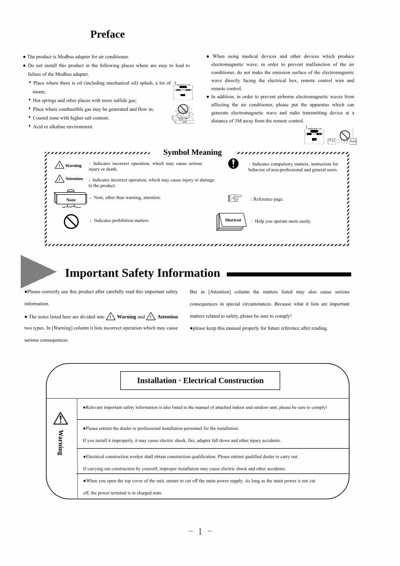
The product is Modbus adapter for air conditioner.
Do not install this product in the following places where are easy to lead to
failure of the Modbus adapter.
·Place where there is oil (including mechanical oil) splash, a lot of
steam;
·Hot springs and other places with more sulfide gas;
·Place where combustible gas may be generated and flow in;
·Coastal zone with higher salt content;
·Acid or alkaline environment.
When using medical devices and other devices which produce
electromagnetic wave, in order to prevent malfunction of the air
conditioner, do not make the emission surface of the electromagnetic
wave directly facing the electrical box, remote control wire and
remote control.
In addition, in order to prevent airborne electromagnetic waves from
affecting the air conditioner, please put the apparatus which can
generate electromagnetic wave and radio transmitting device at a
distance of 3M away from the remote control.
Preface
:Indicates incorrect operation, which may cause injury or damage to the product.
: Indicates incorrect operation, which may cause serious injury or death.
:Note, other than warning, attention.
:Indicates prohibition matters.
: Indicates compulsory matters, instruction for behavior of non-professional and general users.
: Help you operate more easily.
: Reference page.
Symbol Meaning
Installation · Electrical Construction
Please entrust the dealer or professional installation personnel for the installation.
If you install it improperly, it may cause electric shock, fire, adapter fall down and other injury accidents.
Relevant important safety information is also listed in the manual of attached indoor and outdoor unit, please be sure to comply!
Electrical construction worker shall obtain construction qualification. Please entrust qualified dealer to carry out.
If carrying out construction by yourself, improper installation may cause electric shock and other accidents.
When you open the top cover of the unit, ensure to cut off the main power supply. As long as the main power is not cut
off, the power terminal is in charged state.
Warn
ing
Important Safety InformationBut in [Attention] column the matters listed may also cause serious
consequences in special circumstances. Because what it lists are important
matters related to safety, please be sure to comply!
please keep this manual properly for future reference after reading.
Please correctly use this product after carefully read this important safety
information.
The notes listed here are divided into Warning and Attention
two types. In [Warning] column it lists incorrect operation which may cause
serious consequences.
Warning
Attention
Note
Shortcut
- 2 -
Repair and move
When using power adapter, please choose formal manufacturer, 3C certification is essential.
Other warnings and attention
In repair or maintenance, do not let water enter the interior. Electric shock may occur when electrical parts encounter water.
Do not change electrical wiring. Otherwise it may cause major accidents.
In repair and maintenance, please use solid ladder. Otherwise it may overturn and cause injury.
Warning
Warning
When this product is repaired and moved, please consult the dealer or service center designated by the company.
Improper repair and installation may cause electric shock, fire and other accidents.
Attention
Important Safety Information (Continued)
- 3 -
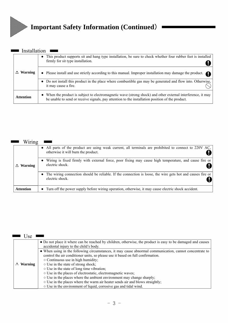
Installation
Warning
This product supports sit and hang type installation, be sure to check whether four rubber feet is installed firmly for sit type installation.
Please install and use strictly according to this manual. Improper installation may damage the product.
Do not install this product in the place where combustible gas may be generated and flow into. Otherwise, it may cause a fire.
Attention When the product is subject to electromagnetic wave (strong shock) and other external interference, it may
be unable to send or receive signals, pay attention to the installation position of the product.
Wiring
Warning
All parts of the product are using weak current, all terminals are prohibited to connect to 220V AC, otherwise it will burn the product.
Wiring is fixed firmly with external force, poor fixing may cause high temperature, and cause fire or electric shock.
The wiring connection should be reliable. If the connection is loose, the wire gets hot and causes fire or electric shock.
Attention Turn off the power supply before wiring operation, otherwise, it may cause electric shock accident.
Use
Warning
Do not place it where can be reached by children, otherwise, the product is easy to be damaged and causes accidental injury to the child’s body.
When using in the following circumstances, it may cause abnormal communication, cannot concentrate to control the air conditioner units, so please use it based on full confirmation. Continuous use in high humidity; Use in the state of strong shock; Use in the state of long time vibration; Use in the places of electrostatic, electromagnetic waves; Use in the places where the ambient environment may change sharply; Use in the places where the warm air heater sends air and blows straightly; Use in the environment of liquid, corrosive gas and tidal wind.
Important Safety Information (Continued)
- 4 -
Attention The company is committed to the improvement of the products constantly, it may subject to change without notice.
This product is only used for conversion between the air conditioner network and control network.
The company does not provide service of changing the product to other use.
Without permission, no part of this manual shall be copied.
If you have any question, please contact the service center designated by the company.
Arrival inspection
Upon receipt of this product, inspect it for any damages incurred in transit.
Check whether the accessories are complete.
Do not use this product in other places which are not specified in this manual.
Important Safety Information (Continued)
- 5 -
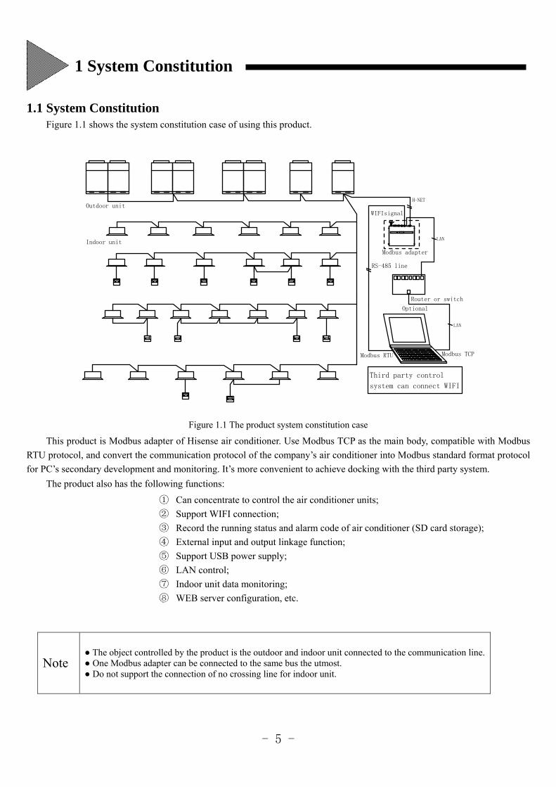
1.1 System Constitution Figure 1.1 shows the system constitution case of using this product.
LAN
Indoor unit
system can connect WIFI
WIFIsignal
LAN
H-NET
Optional
Modbus RTU Modbus TCP
Router or switch
Modbus adapter
Outdoor unit
Third party control
RS-485 line
Figure 1.1 The product system constitution case
This product is Modbus adapter of Hisense air conditioner. Use Modbus TCP as the main body, compatible with Modbus
RTU protocol, and convert the communication protocol of the company’s air conditioner into Modbus standard format protocol
for PC’s secondary development and monitoring. It’s more convenient to achieve docking with the third party system.
The product also has the following functions:
① Can concentrate to control the air conditioner units;
② Support WIFI connection;
③ Record the running status and alarm code of air conditioner (SD card storage);
④ External input and output linkage function;
⑤ Support USB power supply;
⑥ LAN control;
⑦ Indoor unit data monitoring;
⑧ WEB server configuration, etc.
Note The object controlled by the product is the outdoor and indoor unit connected to the communication line. One Modbus adapter can be connected to the same bus the utmost. Do not support the connection of no crossing line for indoor unit.
1 System Constitution
- 6 -
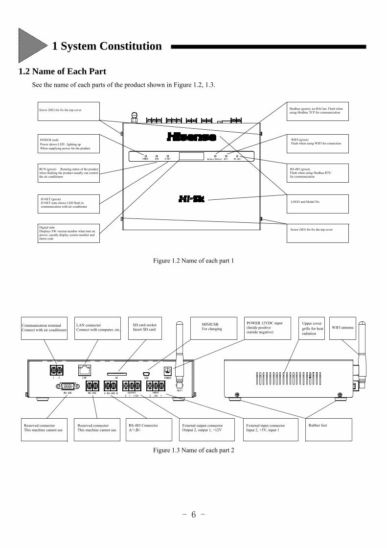
1.2 Name of Each Part
See the name of each parts of the product shown in Figure 1.2, 1.3.
POWER RUN H-NET Modbus/BACnet WIFI RS-485
RUN (green) Running status of the product when flashing the product usually can controlthe air conditioner
Screw (M3) for fix the top cover
POWER (red)Power shows LED , lighting up When supplying power for the product
H-NET (green)H-NET state shows LED flash in communication with air conditioner
Digital tube Displays SW version number when turn on power, usually display system number and alarm code
LOGO and Model No.
WIFI (green)Flash when using WIFI for connection
Modbus (green), no BACnet. Flash when using Modbus TCP for communication
RS-485 (green)Flash when using Modbus RTU for communication
Screw (M3) for fix the top cover
Figure 1.2 Name of each part 1
Communication terminalConnect with air conditioner
1 2 LAN SD
NO USE NO USE A RS-485 B OUTPUT2 1 +12V
INPUT2 +5V 1
WIFI
POWERUSB
LAN connectorConnect with computer, etc.
MINIUSBFor charging
SD card socketInsert SD card
Reserved connectorThis machine cannot use
RS-485 ConnectorA/+,B/-
External output connectorOutput 2, output 1, +12V
External input connectorInput 2, +5V, input 1
POWER 12VDC input (Inside positive outside negative)
Upper cover grille for heat radiation
Rubber feet
WIFI antenna
Reserved connectorThis machine cannot use
Figure 1.3 Name of each part 2
1 System Constitution
- 7 -
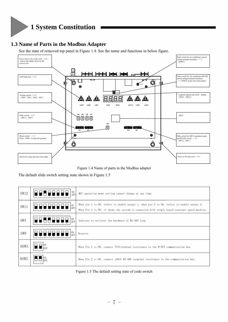
1.3 Name of Parts in the Modbus Adapter
See the state of removed top panel in Figure 1.4. See the name and functions in below figure.
SW12 SW3
SW4
SW9SW11
SW8 SW7SW5SW6
SEG2SEG1 LED6LED5LED10LED7LED8LED9
Screw to fix top cover(× 4)
Slide switch for MCU operation mode and RS-485 circuit (× 2)(SW12、SW3)
MCU
7 segment digital tube LED,display(SEG1、SEG2)
Slide switch for Air conditioner RS-485 circuit setting terminal resistance(× 1 DSW2 on the slave base plate)
Slide switch for air conditioner circuit setting terminal resistance(× 1)(DSW3)
Stud to fix main and slave base plate
Reset switch (× 1)Press(SW4)to reset the product
Slide switch(×2)(SW11、SW9)
Tacting switch(× 4)(SW6、SW5、SW8、SW7)
LED light post(× 6)
Screw hole to fix on the wall(×4), remove the rubber feet,Use M3 screw to fix
DSW2
DSW3
Figure 1.4 Name of parts in the Modbus adapter
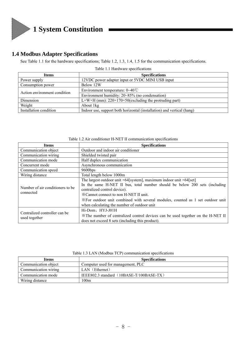
The default slide switch setting state shown in Figure 1.5
ONOFF
871 2 43 5 6
SW9
653 421 7 8OFFONSW11
ONOFF
ONOFF
653 421 7 8
SW3
871 2 43 5 6
SW12
DSW3
DSW2
1 2
ON
OFFON
21
MCU operation mode setting cannot change at any time.
When pin 1 is ON, refers to enable output 1, when pin 2 is ON, refers to enable output 2.
Indicate to activate the hardware of RS-485 loop.
Reserve.
When Pin 1 is ON, connect 75Ωterminal resistance in the H-NET communication bus.
When Pin 2 is ON, connect 120Ω RS-485 terminal resistance in the communication bus.
OFF
When Pin 3 is ON, it shows the system is connected with single board constant speed machine.
Figure 1.5 The default setting state of code switch
1 System Constitution
- 8 -
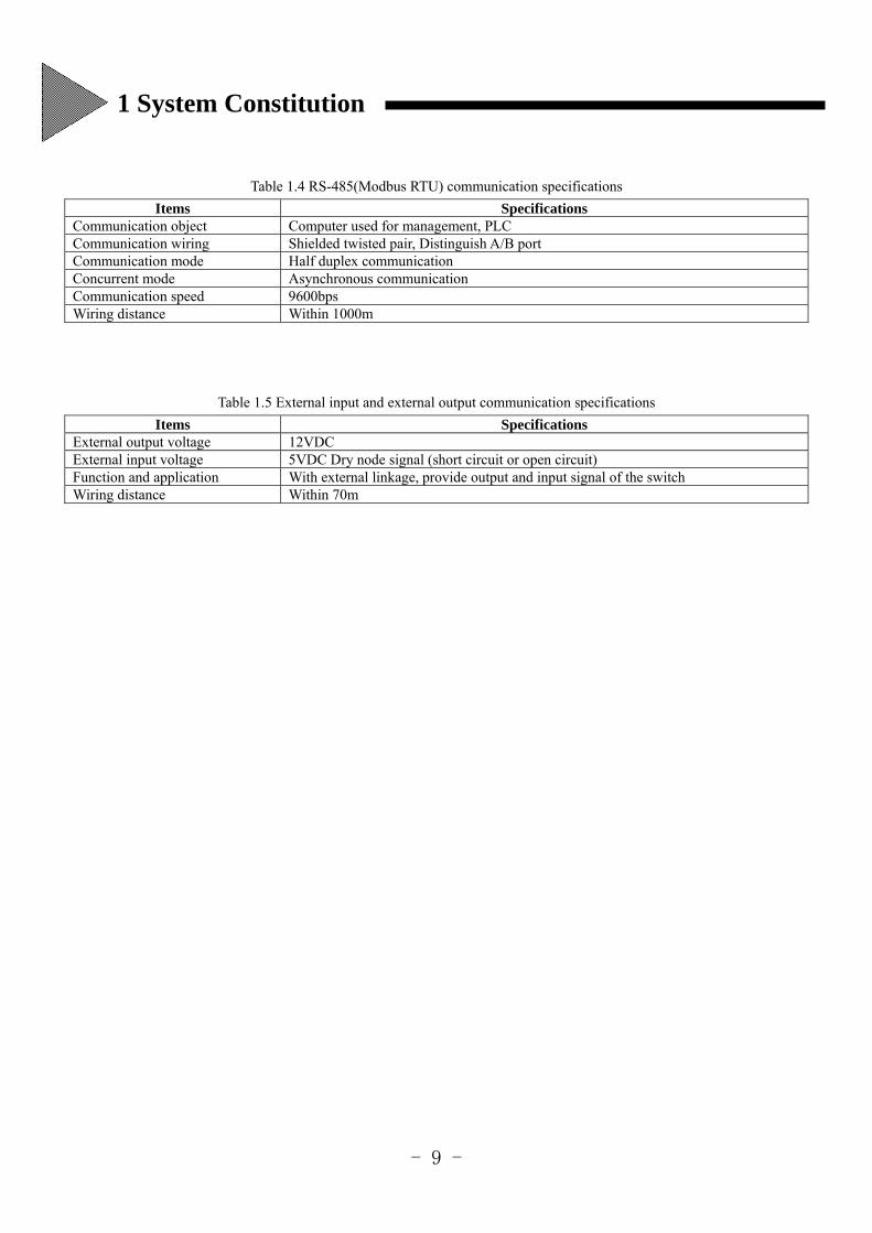
1.4 Modbus Adapter Specifications
See Table 1.1 for the hardware specifications; Table 1.2, 1.3, 1.4, 1.5 for the communication specifications.
Table 1.1 Hardware specifications
Items Specifications Power supply 12VDC power adapter input or 5VDC MINI USB input Consumption power Below 12W
Action environment condition Environment temperature: 0~40 Environment humidity: 20~85% (no condensation)
Dimension L×W×H (mm): 220×170×50(excluding the protruding part) Weight About 1kg Installation condition Indoor use, support both horizontal (installation) and vertical (hang)
Table 1.2 Air conditioner H-NET II communication specifications
Items Specifications Communication object Outdoor and indoor air conditioner Communication wiring Shielded twisted pair Communication mode Half duplex communication Concurrent mode Asynchronous communication Communication speed 9600bps Wiring distance Total length below 1000m
Number of air conditioners to be connected
The largest outdoor unit ×64[system], maximum indoor unit ×64[set] In the same H-NET II bus, total number should be below 200 sets (including centralized control device). ※Cannot connect to non H-NET II unit. ※For outdoor unit combined with several modules, counted as 1 set outdoor unit when calculating the number of outdoor unit
Centralized controller can be used together
Hi-Dom、HYJ-J01H ※The number of centralized control devices can be used together on the H-NET II does not exceed 8 sets (including this product).
Table 1.3 LAN (Modbus TCP) communication specifications
Items Specifications Communication object Computer used for management, PLC Communication wiring LAN(Ethernet) Communication mode IEEE802.3 standard(10BASE-T/100BASE-TX) Wiring distance 100m
1 System Constitution
- 9 -
Table 1.4 RS-485(Modbus RTU) communication specifications
Items Specifications Communication object Computer used for management, PLC Communication wiring Shielded twisted pair, Distinguish A/B port Communication mode Half duplex communication Concurrent mode Asynchronous communication Communication speed 9600bps Wiring distance Within 1000m
Table 1.5 External input and external output communication specifications
Items Specifications External output voltage 12VDC External input voltage 5VDC Dry node signal (short circuit or open circuit) Function and application With external linkage, provide output and input signal of the switch Wiring distance Within 70m
1 System Constitution
- 10 -
This chapter describes the installation method from installing the product to power input. See Table 2.1 showing the process
from installation to power input.
Table 2.1 Installation Process
Sequence Item Content to confirm 1 Select installation place Notes and attention in respect of setting 2 Installation method Installation methods and attentions 3 Wiring connection method Connection method of each wiring 4 Switch setting method Switch content and setting method 5 Power input Matters to confirm
2.1 Installation place Please select a place which meets the following conditions for installation:
(1) The place where the [Preface] of the installation instruction manual describes.
(2) For horizontal installation, pay attention to select a relatively stable table.
For vertical (wall hang) installation, please use M3 screws to fix it on the sturdy wall.
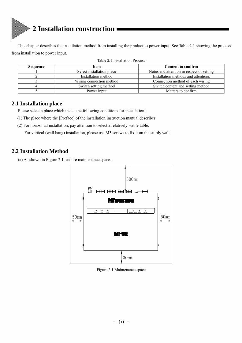
2.2 Installation Method
(a) As shown in Figure 2.1, ensure maintenance space.
50mm50mm
30mm
300mm
POWER RUN H-NET Modbus/BACnet WIFI RS-485
Figure 2.1 Maintenance space
2 Installation construction
- 11 -
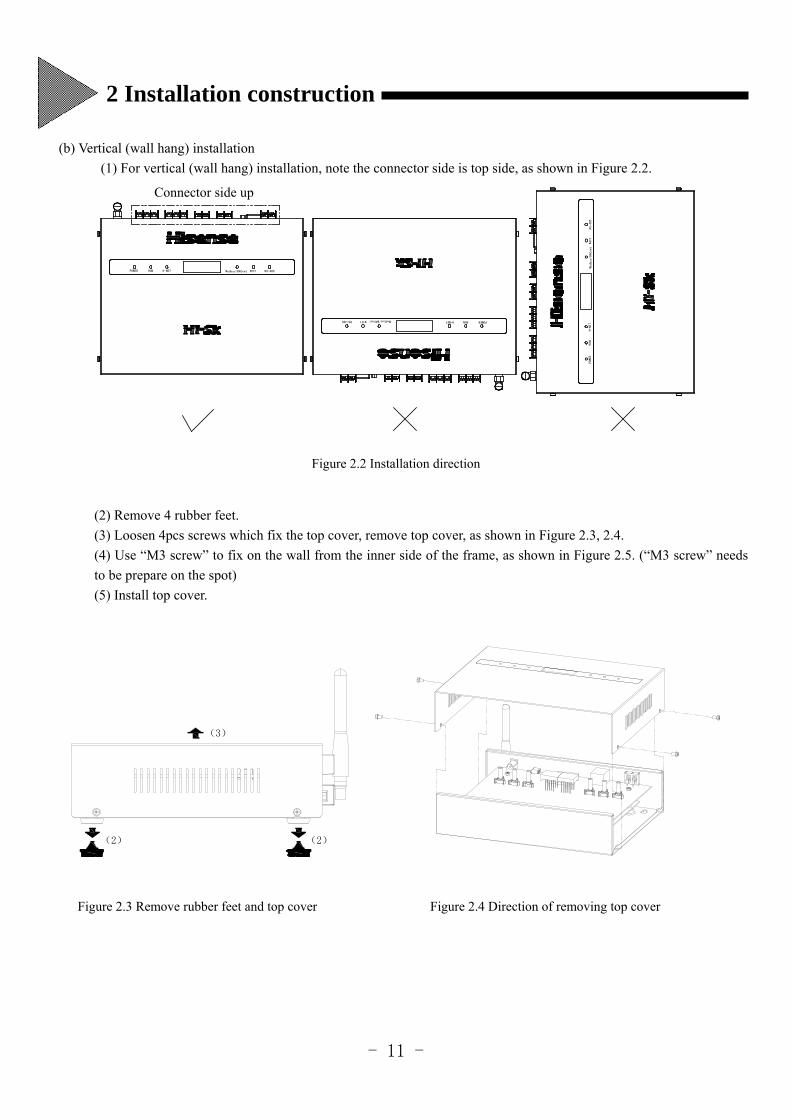
(b) Vertical (wall hang) installation
(1) For vertical (wall hang) installation, note the connector side is top side, as shown in Figure 2.2.
RS-485
WIFI
Connector side up
POWER RUN H-NET Modbus/BACnet WIFI RS-485
RS-485 WIFI Modbus/BACnet H-NET RUN POWER
Modbus/BACnet
H-NET
RUN
POWER
Figure 2.2 Installation direction
(2) Remove 4 rubber feet.
(3) Loosen 4pcs screws which fix the top cover, remove top cover, as shown in Figure 2.3, 2.4.
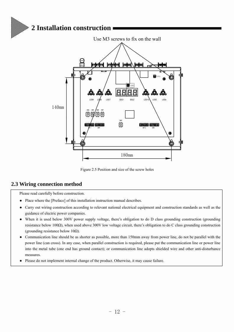
(4) Use “M3 screw” to fix on the wall from the inner side of the frame, as shown in Figure 2.5. (“M3 screw” needs
to be prepare on the spot)
(5) Install top cover.
(2) (2)
(3)
Figure 2.3 Remove rubber feet and top cover Figure 2.4 Direction of removing top cover
2 Installation construction
- 12 -
180mm
Use M3 screws to fix on the wall
140mmSW6 SW5 SW7SW8
SW11 SW9
SW4
SW3SW12
DSW3
DSW2
LED9 LED8 LED7 LED10 LED5 LED6SEG1 SEG2
Figure 2.5 Position and size of the screw holes
2.3 Wiring connection method
Please read carefully before construction.
Place where the [Preface] of this installation instruction manual describes.
Carry out wiring construction according to relevant national electrical equipment and construction standards as well as the
guidance of electric power companies.
When it is used below 300V power supply voltage, there’s obligation to do D class grounding construction (grounding
resistance below 100Ω), when used above 300V low voltage circuit, there’s obligation to do C class grounding construction
(grounding resistance below 10Ω).
Communication line should be as shorter as possible, more than 150mm away from power line, do not be parallel with the
power line (can cross). In any case, when parallel construction is required, please put the communication line or power line
into the metal tube (one end has ground contact); or communication line adopts shielded wire and other anti-disturbance
measures.
Please do not implement internal change of the product. Otherwise, it may cause failure.
2 Installation construction
- 13 -
2.3.1 Wiring Method
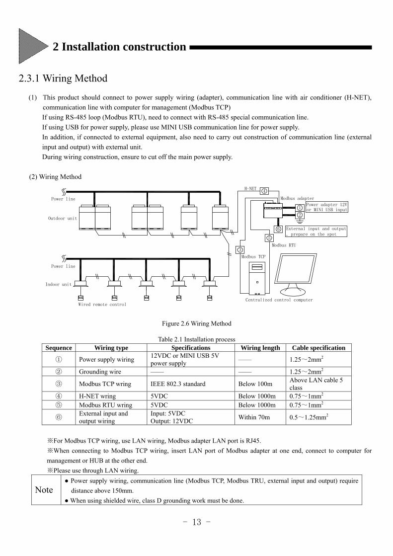
(1) This product should connect to power supply wiring (adapter), communication line with air conditioner (H-NET),
communication line with computer for management (Modbus TCP)
If using RS-485 loop (Modbus RTU), need to connect with RS-485 special communication line.
If using USB for power supply, please use MINI USB communication line for power supply.
In addition, if connected to external equipment, also need to carry out construction of communication line (external
input and output) with external unit.
During wiring construction, ensure to cut off the main power supply.
(2) Wiring Method
, prepare on the spot
Power line
Wired remote control
Indoor unit
Outdoor unit
Centralized control computer
H-NET
Power line Modbus adapter
3
Modbus TCP
4
1Power adapter 12Vor MINI USB input
2
5
6
Modbus RTU
External input and output
Figure 2.6 Wiring Method
Table 2.1 Installation process Sequence Wiring type Specifications Wiring length Cable specification
① Power supply wiring 12VDC or MINI USB 5V power supply
—— 1.25~2mm2
② Grounding wire —— —— 1.25~2mm2
③ Modbus TCP wring IEEE 802.3 standard Below 100m Above LAN cable 5 class
④ H-NET wring 5VDC Below 1000m 0.75~1mm2 ⑤ Modbus RTU wring 5VDC Below 1000m 0.75~1mm2
⑥ External input and output wiring
Input: 5VDC Output: 12VDC
Within 70m 0.5~1.25mm2
※For Modbus TCP wiring, use LAN wiring, Modbus adapter LAN port is RJ45.
※When connecting to Modbus TCP wiring, insert LAN port of Modbus adapter at one end, connect to computer for
management or HUB at the other end.
※Please use through LAN wiring.
Note
Power supply wiring, communication line (Modbus TCP, Modbus TRU, external input and output) require
distance above 150mm.
When using shielded wire, class D grounding work must be done.
2 Installation construction
- 14 -
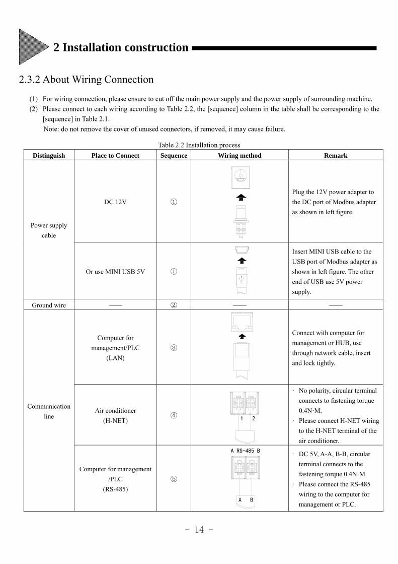
2.3.2 About Wiring Connection
(1) For wiring connection, please ensure to cut off the main power supply and the power supply of surrounding machine.
(2) Please connect to each wiring according to Table 2.2, the [sequence] column in the table shall be corresponding to the
[sequence] in Table 2.1.
Note: do not remove the cover of unused connectors, if removed, it may cause failure.
Table 2.2 Installation process
Distinguish Place to Connect Sequence Wiring method Remark
Power supply
cable
DC 12V ①
Plug the 12V power adapter to
the DC port of Modbus adapter
as shown in left figure.
Or use MINI USB 5V ①
Insert MINI USB cable to the
USB port of Modbus adapter as
shown in left figure. The other
end of USB use 5V power
supply.
Ground wire —— ② —— ——
Communication
line
Computer for
management/PLC
(LAN)
③
Connect with computer for
management or HUB, use
through network cable, insert
and lock tightly.
Air conditioner
(H-NET) ④
· No polarity, circular terminal
connects to fastening torque
0.4N·M.
· Please connect H-NET wiring
to the H-NET terminal of the
air conditioner.
Computer for management
/PLC
(RS-485)
⑤
· DC 5V, A-A, B-B, circular
terminal connects to the
fastening torque 0.4N·M.
· Please connect the RS-485
wiring to the computer for
management or PLC.
A RS-485 B
A B
1 2
2 Installation construction
- 15 -
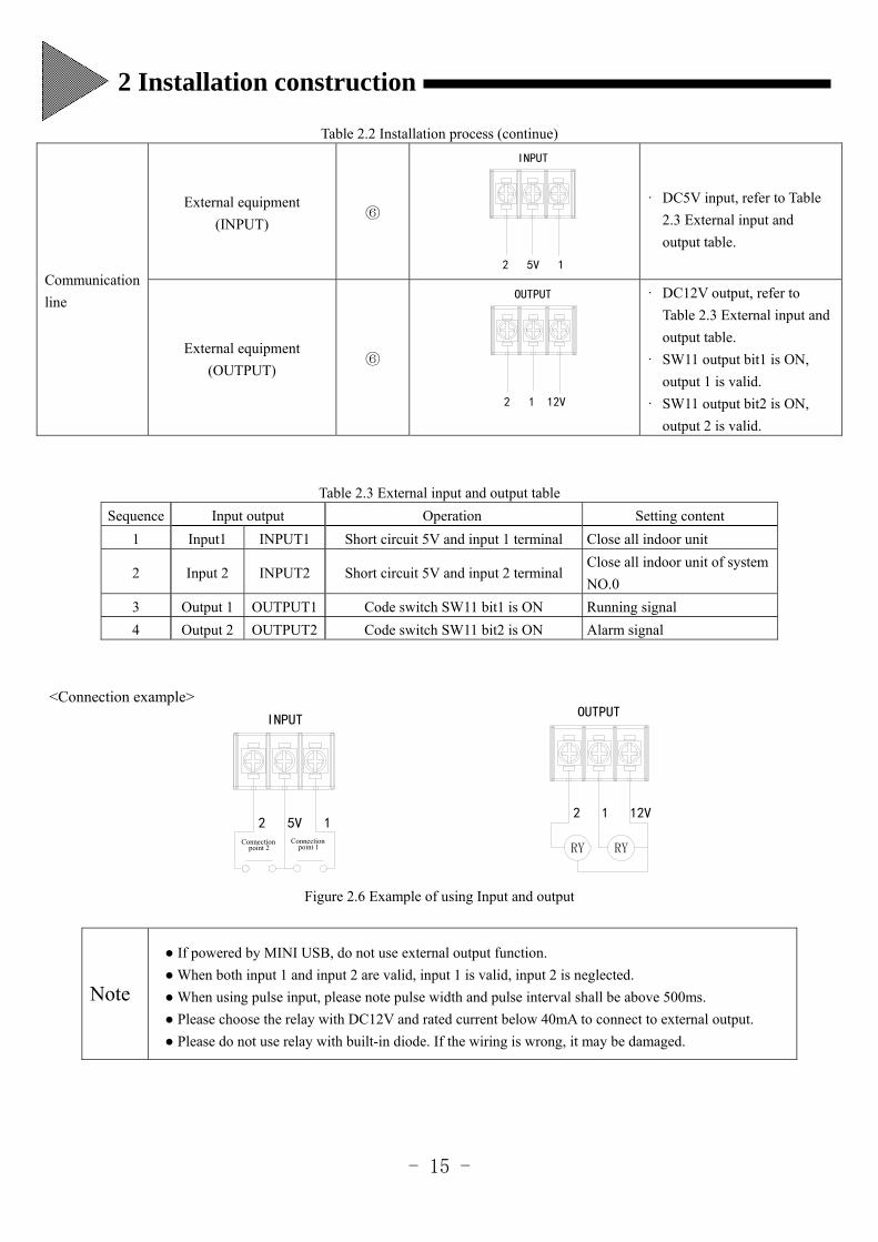
Table 2.2 Installation process (continue)
Communication
line
External equipment
(INPUT) ⑥
· DC5V input, refer to Table
2.3 External input and
output table.
External equipment
(OUTPUT) ⑥
· DC12V output, refer to
Table 2.3 External input and
output table.
· SW11 output bit1 is ON,
output 1 is valid.
· SW11 output bit2 is ON,
output 2 is valid.
Table 2.3 External input and output table
Sequence Input output Operation Setting content
1 Input1 INPUT1 Short circuit 5V and input 1 terminal Close all indoor unit
2 Input 2 INPUT2 Short circuit 5V and input 2 terminal Close all indoor unit of system
NO.0
3 Output 1 OUTPUT1 Code switch SW11 bit1 is ON Running signal
4 Output 2 OUTPUT2 Code switch SW11 bit2 is ON Alarm signal
<Connection example>
Figure 2.6 Example of using Input and output
Note
If powered by MINI USB, do not use external output function.
When both input 1 and input 2 are valid, input 1 is valid, input 2 is neglected.
When using pulse input, please note pulse width and pulse interval shall be above 500ms.
Please choose the relay with DC12V and rated current below 40mA to connect to external output.
Please do not use relay with built-in diode. If the wiring is wrong, it may be damaged.
INPUT
2 5V 1
接点1接点2
OUTPUT
2 1 12V
RYRY
2 5V 1
INPUT
2 1 12V
OUTPUT
Connection point 2
Connection point 1
2 Installation construction
- 16 -
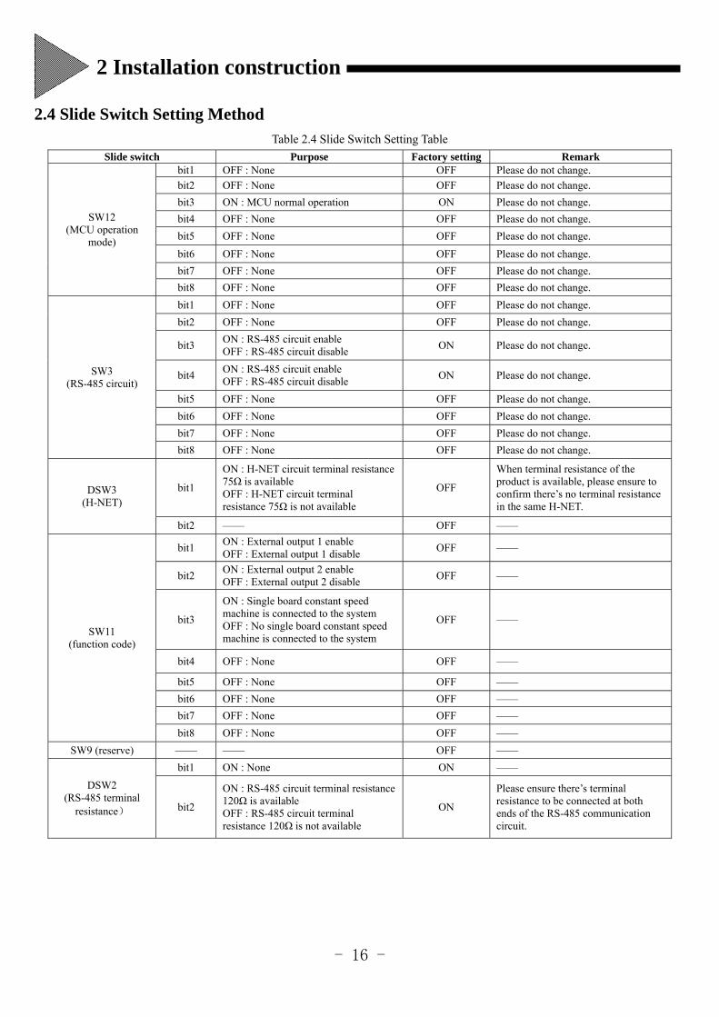
2.4 Slide Switch Setting Method
Table 2.4 Slide Switch Setting Table
Slide switch Purpose Factory setting Remark
SW12 (MCU operation
mode)
bit1 OFF : None OFF Please do not change.
bit2 OFF : None OFF Please do not change.
bit3 ON : MCU normal operation ON Please do not change.
bit4 OFF : None OFF Please do not change.
bit5 OFF : None OFF Please do not change.
bit6 OFF : None OFF Please do not change.
bit7 OFF : None OFF Please do not change.
bit8 OFF : None OFF Please do not change.
SW3 (RS-485 circuit)
bit1 OFF : None OFF Please do not change.
bit2 OFF : None OFF Please do not change.
bit3 ON : RS-485 circuit enable OFF : RS-485 circuit disable
ON Please do not change.
bit4 ON : RS-485 circuit enable OFF : RS-485 circuit disable
ON Please do not change.
bit5 OFF : None OFF Please do not change.
bit6 OFF : None OFF Please do not change.
bit7 OFF : None OFF Please do not change.
bit8 OFF : None OFF Please do not change.
DSW3 (H-NET)
bit1
ON : H-NET circuit terminal resistance 75Ω is available OFF : H-NET circuit terminal resistance 75Ω is not available
OFF
When terminal resistance of the product is available, please ensure to confirm there’s no terminal resistance in the same H-NET.
bit2 —— OFF ——
SW11 (function code)
bit1 ON : External output 1 enable OFF : External output 1 disable
OFF ——
bit2 ON : External output 2 enable OFF : External output 2 disable
OFF ——
bit3
ON : Single board constant speed machine is connected to the system OFF : No single board constant speed machine is connected to the system
OFF ——
bit4 OFF : None OFF ——
bit5 OFF : None OFF ——
bit6 OFF : None OFF ——
bit7 OFF : None OFF ——
bit8 OFF : None OFF ——
SW9 (reserve) —— —— OFF ——
DSW2 (RS-485 terminal
resistance)
bit1 ON : None ON ——
bit2
ON : RS-485 circuit terminal resistance 120Ω is available OFF : RS-485 circuit terminal resistance 120Ω is not available
ON
Please ensure there’s terminal resistance to be connected at both ends of the RS-485 communication circuit.
2 Installation construction
- 17 -
Please change the slide switch setting before input power supply.
The slide switch setting table of this product is shown in Table 2.4. In addition, according to the using situation on the spot,
sometimes it may need to change factory setting.
2.5 Power Supply Input When setting the slide switch, please refer to the following procedures.
(1) Turn off the power supply of the product, open the top cover.
(2) Change switch setting.
(3) Complete installation, wiring connection, by end of switch setting, close the top cover, tighten and fix the screws, please
complete the following operation, then input power supply.
※ Please connect to the power supply of all connected air conditioner group.
※ Carry out test run for all air conditioners, ensure that all air conditioners can work properly.
※ Please input main power supply.
※ Please input the power supply of the machine.
POWER lights up.
After about 10s, start the connection confirmation of the air conditioner.
During the air conditioner connection process, EUN lights up constantly.
※ It takes about 20 minutes the longest to complete the connection (according to actual connection quantity of the air
conditioner), when the product enters normal running air conditioner, RUN light flashes in 1Hz.
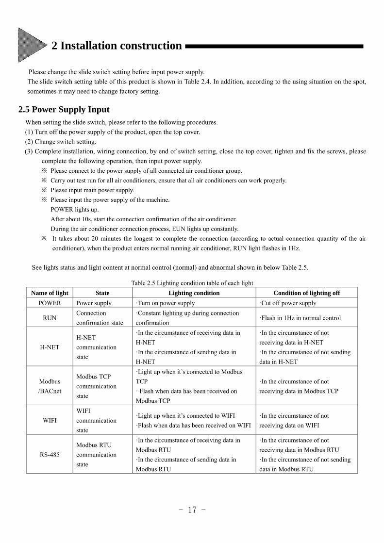
See lights status and light content at normal control (normal) and abnormal shown in below Table 2.5.
Table 2.5 Lighting condition table of each light
Name of light State Lighting condition Condition of lighting off
POWER Power supply ·Turn on power supply ·Cut off power supply
RUN Connection
confirmation state
·Constant lighting up during connection
confirmation ·Flash in 1Hz in normal control
H-NET
H-NET
communication
state
·In the circumstance of receiving data in
H-NET
·In the circumstance of sending data in
H-NET
·In the circumstance of not
receiving data in H-NET
·In the circumstance of not sending
data in H-NET
Modbus
/BACnet
Modbus TCP
communication
state
·Light up when it’s connected to Modbus
TCP
· Flash when data has been received on
Modbus TCP
·In the circumstance of not
receiving data in Modbus TCP
WIFI
WIFI
communication
state
·Light up when it’s connected to WIFI
·Flash when data has been received on WIFI
·In the circumstance of not
receiving data on WIFI
RS-485
Modbus RTU
communication
state
·In the circumstance of receiving data in
Modbus RTU
·In the circumstance of sending data in
Modbus RTU
·In the circumstance of not
receiving data in Modbus RTU
·In the circumstance of not sending
data in Modbus RTU
2 Installation construction
- 18 -
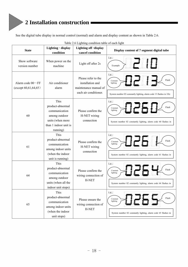
See the digital tube display in normal control (normal) and alarm and display content as shown in Table 2.6.
Table 2.6 Lighting condition table of each light
State Lighting · display
condition
Lighting off ·display
cancel condition Display content of 7 segment digital tube
Show software
version number
When power on the
machine Light off after 2s
i.e.:
Alarm code 00~FF
(except 60,61,64,65)
Air conditioner
alarm
Please refer to the
installation and
maintenance manual of
each air conditioner.
i.e.:
60
This
product-abnormal
communication
among outdoor
units (when more
than 1 indoor unit is
running)
Please confirm the
H-NET wiring
connection
i.e.:
61
This
product-abnormal
communication
among indoor units
(when the indoor
unit is running)
Please confirm the
H-NET wiring
connection
i.e.:
64
This
product-abnormal
communication
among outdoor
units (when all the
indoor unit stops)
Please confirm the
wiring connection of
H-NET
i.e.:
65
This
product-abnormal
communication
among indoor units
(when the indoor
unit stops)
Please ensure the
wiring connection of
H-NET
i.e.:
Flash
Constant lighting
Flash
System number 02 constantly lighting, alarm code 13 flashes in 1Hz
System number 02 constantly lighting, alarm code 60 flashes in
System number 02 constantly lighting, alarm code 61 flashes in
System number 02 constantly lighting, alarm code 64 flashes in
System number 02 constantly lighting, alarm code 65 flashes in
Constant lighting
Flash
Constant lighting
Flash
Constant lighting
Flash
Example
Constant lighting
2 Installation construction
- 19 -
At the start of air conditioner season, all the indoor units must be test run, and confirm whether the product is correctly
running on the next day.
The computer for management shall be used as the special computer for this system.
One computer for management can connect to many sets of units, but several units cannot be in the same H-NET bus.
Note The following operation is in the precondition that all the test run and adapter installation are completed and the power
supply is connected.
3.1 Configuration of Modbus Adapter
Set up the product so that it can communicate with PC.
3.1.1 IP Address Setting
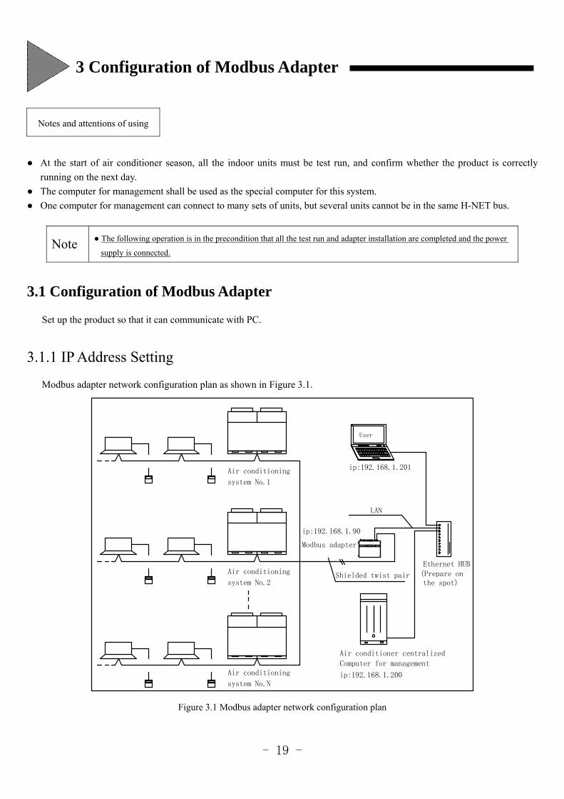
Modbus adapter network configuration plan as shown in Figure 3.1.
Modbus adapter
(Prepare onEthernet HUB
ip:192.168.1.90
ip:192.168.1.200
Computer for management
Air conditioning
Shielded twist pair
Air conditioner centralized
LAN
User
ip:192.168.1.201
system No.1
Air conditioning
system No.2
Air conditioning
system No.N
the spot)
Figure 3.1 Modbus adapter network configuration plan
Notes and attentions of using
3 Configuration of Modbus Adapter
- 20 -
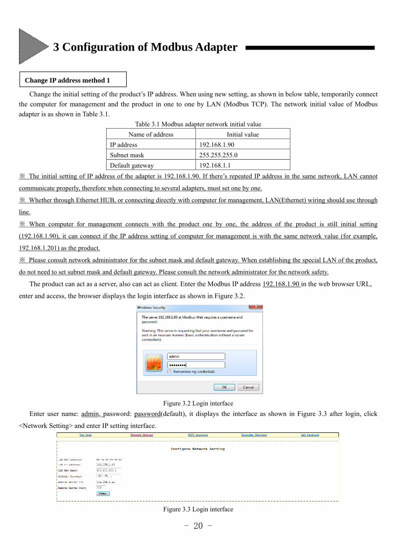
Change the initial setting of the product’s IP address. When using new setting, as shown in below table, temporarily connect
the computer for management and the product in one to one by LAN (Modbus TCP). The network initial value of Modbus
adapter is as shown in Table 3.1.
Table 3.1 Modbus adapter network initial value
Name of address Initial value
IP address 192.168.1.90
Subnet mask 255.255.255.0
Default gateway 192.168.1.1
※ The initial setting of IP address of the adapter is 192.168.1.90. If there’s repeated IP address in the same network, LAN cannot
communicate properly, therefore when connecting to several adapters, must set one by one.
※ Whether through Ethernet HUB, or connecting directly with computer for management, LAN(Ethernet) wiring should use through
line.
※ When computer for management connects with the product one by one, the address of the product is still initial setting
(192.168.1.90), it can connect if the IP address setting of computer for management is with the same network value (for example,
192.168.1.201) as the product.
※ Please consult network administrator for the subnet mask and default gateway. When establishing the special LAN of the product,
do not need to set subnet mask and default gateway. Please consult the network administrator for the network safety.
The product can act as a server, also can act as client. Enter the Modbus IP address 192.168.1.90 in the web browser URL,
enter and access, the browser displays the login interface as shown in Figure 3.2.
Figure 3.2 Login interface
Enter user name: admin, password: password(default), it displays the interface as shown in Figure 3.3 after login, click
<Network Setting> and enter IP setting interface.
Figure 3.3 Login interface
Change IP address method 1
3 Configuration of Modbus Adapter
- 21 -
The other options shown in above figure have nothing to do with the IP address setting, please do not change it, or it may
cause consequences that cannot return!
Note
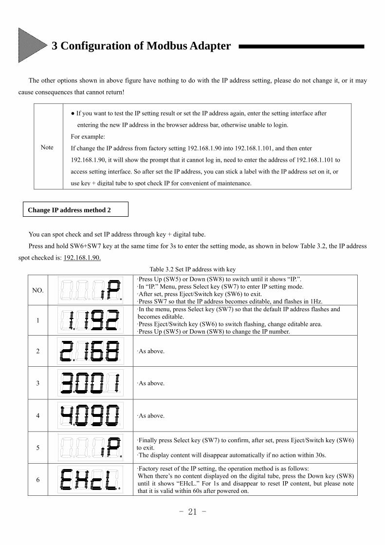
You can spot check and set IP address through key + digital tube.
Press and hold SW6+SW7 key at the same time for 3s to enter the setting mode, as shown in below Table 3.2, the IP address
spot checked is: 192.168.1.90.
Table 3.2 Set IP address with key
NO.
·Press Up (SW5) or Down (SW8) to switch until it shows “IP.”. ·In “IP.” Menu, press Select key (SW7) to enter IP setting mode. ·After set, press Eject/Switch key (SW6) to exit. ·Press SW7 so that the IP address becomes editable, and flashes in 1Hz.
1
·In the menu, press Select key (SW7) so that the default IP address flashes and becomes editable. ·Press Eject/Switch key (SW6) to switch flashing, change editable area. ·Press Up (SW5) or Down (SW8) to change the IP number.
2
·As above.
3
·As above.
4
·As above.
5
·Finally press Select key (SW7) to confirm, after set, press Eject/Switch key (SW6) to exit. ·The display content will disappear automatically if no action within 30s.
6
·Factory reset of the IP setting, the operation method is as follows: When there’s no content displayed on the digital tube, press the Down key (SW8) until it shows “EHcL.” For 1s and disappear to reset IP content, but please note that it is valid within 60s after powered on.
If you want to test the IP setting result or set the IP address again, enter the setting interface after
entering the new IP address in the browser address bar, otherwise unable to login.
For example:
If change the IP address from factory setting 192.168.1.90 into 192.168.1.101, and then enter
192.168.1.90, it will show the prompt that it cannot log in, need to enter the address of 192.168.1.101 to
access setting interface. So after set the IP address, you can stick a label with the IP address set on it, or
use key + digital tube to spot check IP for convenient of maintenance.
Change IP address method 2
3 Configuration of Modbus Adapter
- 22 -
You can log in the WEB server of the WIFI module to configure the network information.
The factory default setting of WIFI IP address of the Modbus adapter is: 192.168.1.1, use computer for management or
smart devices which can connect to WIFI to establish connection with the Modbus adapter.
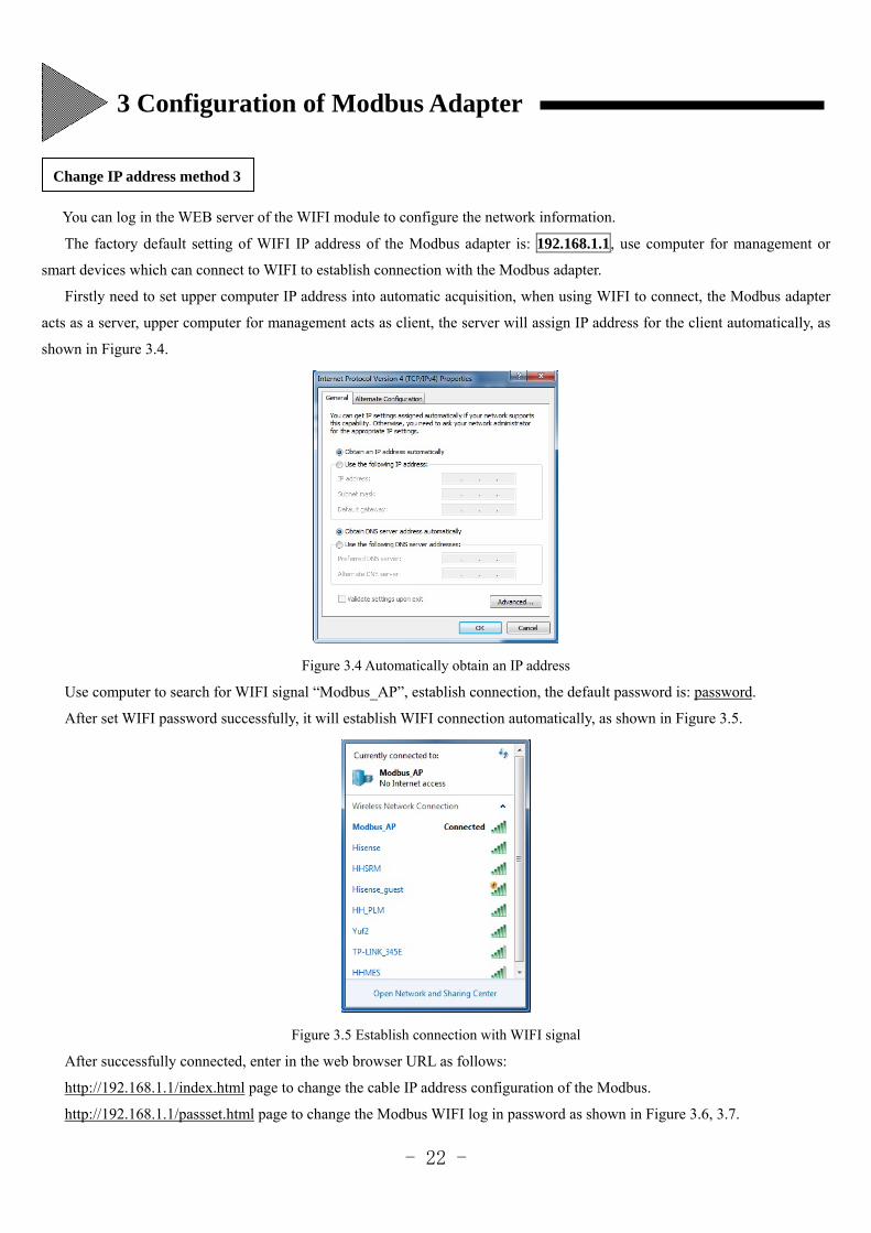
Firstly need to set upper computer IP address into automatic acquisition, when using WIFI to connect, the Modbus adapter
acts as a server, upper computer for management acts as client, the server will assign IP address for the client automatically, as
shown in Figure 3.4.
Figure 3.4 Automatically obtain an IP address
Use computer to search for WIFI signal “Modbus_AP”, establish connection, the default password is: password.
After set WIFI password successfully, it will establish WIFI connection automatically, as shown in Figure 3.5.
Figure 3.5 Establish connection with WIFI signal
After successfully connected, enter in the web browser URL as follows:
http://192.168.1.1/index.html page to change the cable IP address configuration of the Modbus.
http://192.168.1.1/passset.html page to change the Modbus WIFI log in password as shown in Figure 3.6, 3.7.
Change IP address method 3
3 Configuration of Modbus Adapter
- 23 -
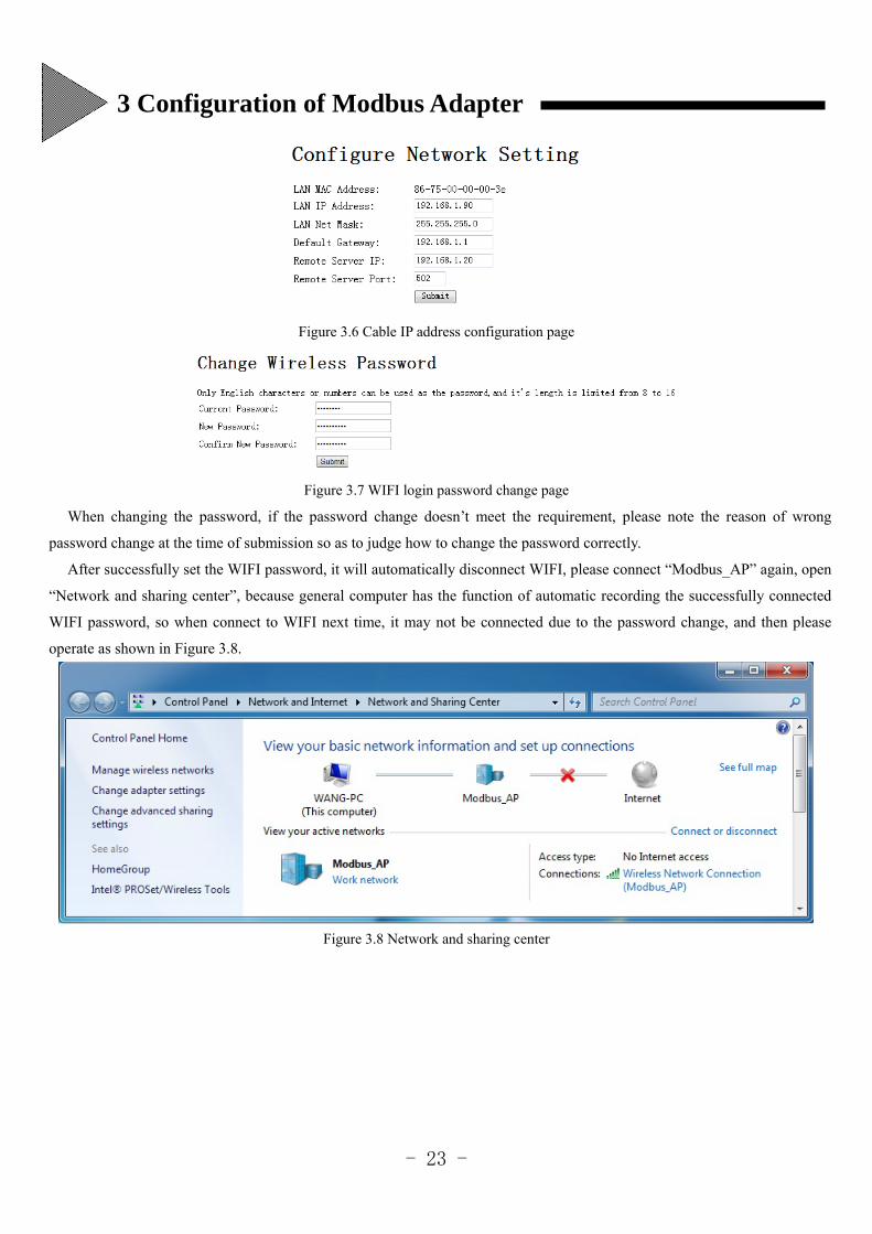
Figure 3.6 Cable IP address configuration page
Figure 3.7 WIFI login password change page
When changing the password, if the password change doesn’t meet the requirement, please note the reason of wrong
password change at the time of submission so as to judge how to change the password correctly.
After successfully set the WIFI password, it will automatically disconnect WIFI, please connect “Modbus_AP” again, open
“Network and sharing center”, because general computer has the function of automatic recording the successfully connected
WIFI password, so when connect to WIFI next time, it may not be connected due to the password change, and then please
operate as shown in Figure 3.8.
Figure 3.8 Network and sharing center
3 Configuration of Modbus Adapter

- 24 -
Click “Manage wireless network”. As shown in Figure 3.9.
Figure 3.9 Manage wireless network
Select “Modbus_AP”. right click “Property” with the mouse. Enter the changed password as shown in Figure 3.10.
Figure 3.10 Enter new password window
After entered new password, click Ok to reconnect WIFI.
3 Configuration of Modbus Adapter
- 25 -
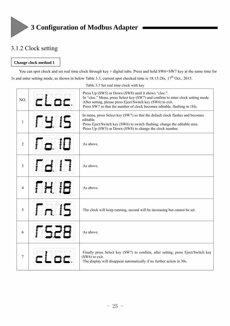
3.1.2 Clock setting
You can spot check and set real time clock through key + digital tube. Press and hold SW6+SW7 key at the same time for
3s and enter setting mode, as shown in below Table 3.3, current spot checked time is 18:15:28s, 17th Oct., 2015.
Table 3.3 Set real time clock with key
NO.
·Press Up (SW5) or Down (SW8) until it shows “cloc.”. ·In “cloc.” Menu, press Select key (SW7) and confirm to enter clock setting mode. ·After setting, please press Eject/Switch key (SW6) to exit. ·Press SW7 so that the number of clock becomes editable, flashing in 1Hz.
1
·In menu, press Select key (SW7) so that the default clock flashes and becomes editable. ·Press Eject/Switch key (SW6) to switch flashing, change the editable area. ·Press Up (SW5) or Down (SW8) to change the clock number.
2
·As above.
3
·As above.
4
·As above.
5
·The clock will keep running, second will be increasing but cannot be set.
6
·As above.
7
·Finally press Select key (SW7) to confirm, after setting, press Eject/Switch key (SW6) to exit. ·The display will disappear automatically if no further action in 30s.
Change clock method 1
3 Configuration of Modbus Adapter
- 26 -
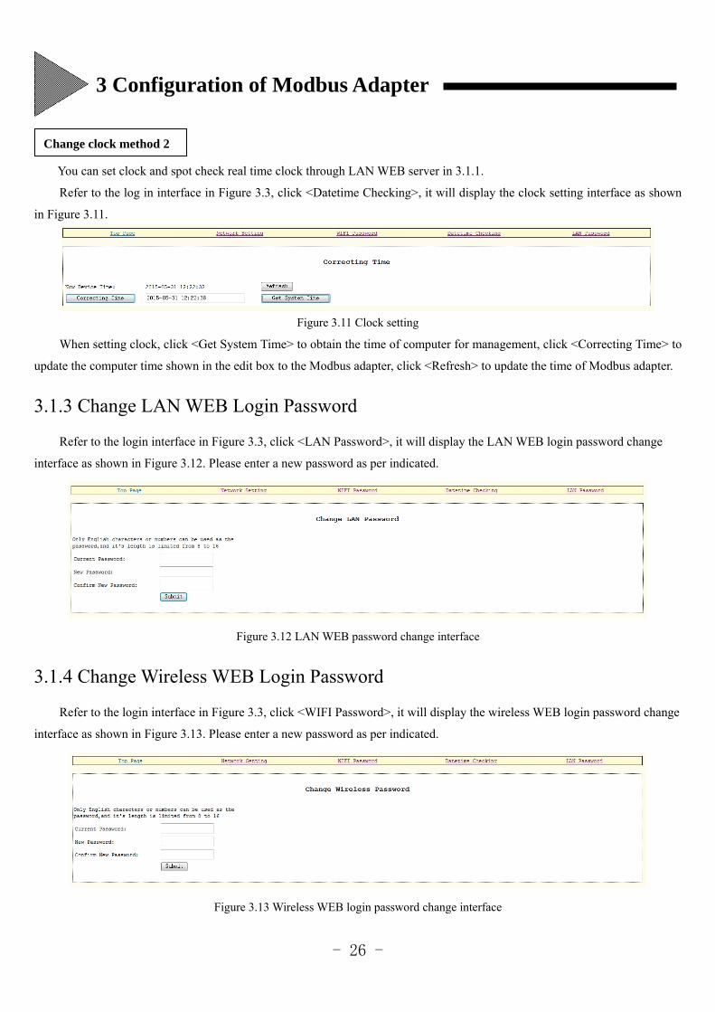
You can set clock and spot check real time clock through LAN WEB server in 3.1.1.
Refer to the log in interface in Figure 3.3, click <Datetime Checking>, it will display the clock setting interface as shown
in Figure 3.11.
Figure 3.11 Clock setting
When setting clock, click <Get System Time> to obtain the time of computer for management, click <Correcting Time> to
update the computer time shown in the edit box to the Modbus adapter, click <Refresh> to update the time of Modbus adapter.
3.1.3 Change LAN WEB Login Password
Refer to the login interface in Figure 3.3, click <LAN Password>, it will display the LAN WEB login password change
interface as shown in Figure 3.12. Please enter a new password as per indicated.
Figure 3.12 LAN WEB password change interface
3.1.4 Change Wireless WEB Login Password
Refer to the login interface in Figure 3.3, click <WIFI Password>, it will display the wireless WEB login password change
interface as shown in Figure 3.13. Please enter a new password as per indicated.
Figure 3.13 Wireless WEB login password change interface
Change clock method 2
3 Configuration of Modbus Adapter
- 27 -
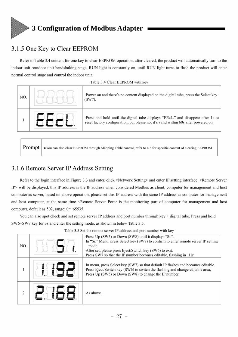
3.1.5 One Key to Clear EEPROM
Refer to Table 3.4 content for one key to clear EEPROM operation, after cleared, the product will automatically turn to the
indoor unit ·outdoor unit handshaking stage, RUN light is constantly on, until RUN light turns to flash the product will enter
normal control stage and control the indoor unit.
Table 3.4 Clear EEPROM with key
NO.
·Power on and there’s no content displayed on the digital tube, press the Select key (SW7).
1
·Press and hold until the digital tube displays “EEcL.” and disappear after 1s to reset factory configuration, but please not it’s valid within 60s after powered on.
Prompt You can also clear EEPROM through Mapping Table control, refer to 4.8 for specific content of clearing EEPROM.
3.1.6 Remote Server IP Address Setting
Refer to the login interface in Figure 3.3 and enter, click <Network Setting> and enter IP setting interface. <Remote Server
IP> will be displayed, this IP address is the IP address when considered Modbus as client, computer for management and host
computer as server, based on above operation, please set this IP address with the same IP address as computer for management
and host computer, at the same time <Remote Server Port> is the monitoring port of computer for management and host
computer, default as 502, range: 0~65535.
You can also spot check and set remote server IP address and port number through key + digital tube. Press and hold
SW6+SW7 key for 3s and enter the setting mode, as shown in below Table 3.5.
Table 3.5 Set the remote server IP address and port number with key
NO.
·Press Up (SW5) or Down (SW8) until it displays “Si.”. ·In “Si.” Menu, press Select key (SW7) to confirm to enter remote server IP setting
mode. ·After set, please press Eject/Switch key (SW6) to exit. ·Press SW7 so that the IP number becomes editable, flashing in 1Hz.
1
·In menu, press Select key (SW7) so that default IP flashes and becomes editable. ·Press Eject/Switch key (SW6) to switch the flashing and change editable area. ·Press Up (SW5) or Down (SW8) to change the IP number.
2
·As above.
3 Configuration of Modbus Adapter
- 28 -
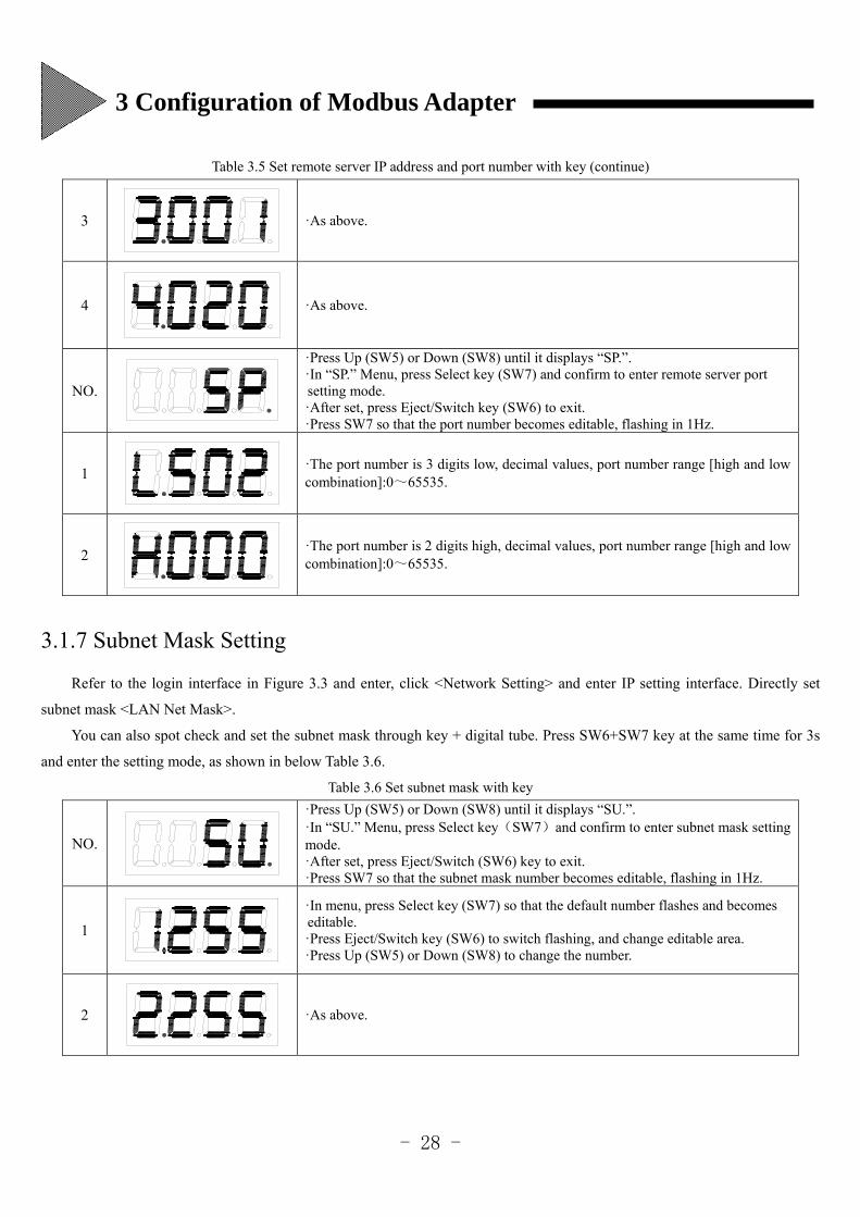
Table 3.5 Set remote server IP address and port number with key (continue)
3
·As above.
4
·As above.
NO.
·Press Up (SW5) or Down (SW8) until it displays “SP.”. ·In “SP.” Menu, press Select key (SW7) and confirm to enter remote server port setting mode. ·After set, press Eject/Switch key (SW6) to exit. ·Press SW7 so that the port number becomes editable, flashing in 1Hz.
1
·The port number is 3 digits low, decimal values, port number range [high and low combination]:0~65535.
2
·The port number is 2 digits high, decimal values, port number range [high and low combination]:0~65535.
3.1.7 Subnet Mask Setting
Refer to the login interface in Figure 3.3 and enter, click <Network Setting> and enter IP setting interface. Directly set
subnet mask <LAN Net Mask>.
You can also spot check and set the subnet mask through key + digital tube. Press SW6+SW7 key at the same time for 3s
and enter the setting mode, as shown in below Table 3.6.
Table 3.6 Set subnet mask with key
NO.
·Press Up (SW5) or Down (SW8) until it displays “SU.”. ·In “SU.” Menu, press Select key(SW7)and confirm to enter subnet mask setting mode. ·After set, press Eject/Switch (SW6) key to exit. ·Press SW7 so that the subnet mask number becomes editable, flashing in 1Hz.
1
·In menu, press Select key (SW7) so that the default number flashes and becomes editable. ·Press Eject/Switch key (SW6) to switch flashing, and change editable area. ·Press Up (SW5) or Down (SW8) to change the number.
2
·As above.
3 Configuration of Modbus Adapter
- 29 -
Table 3.6 Set subnet mask with key (continue)
3
·As above.
4
·As above.
5
·Finally press select key (SW7) to confirm, after setting, press Eject/Switch key (SW6) to exit. ·The display content will automatically disappear if no further action within 30 s.
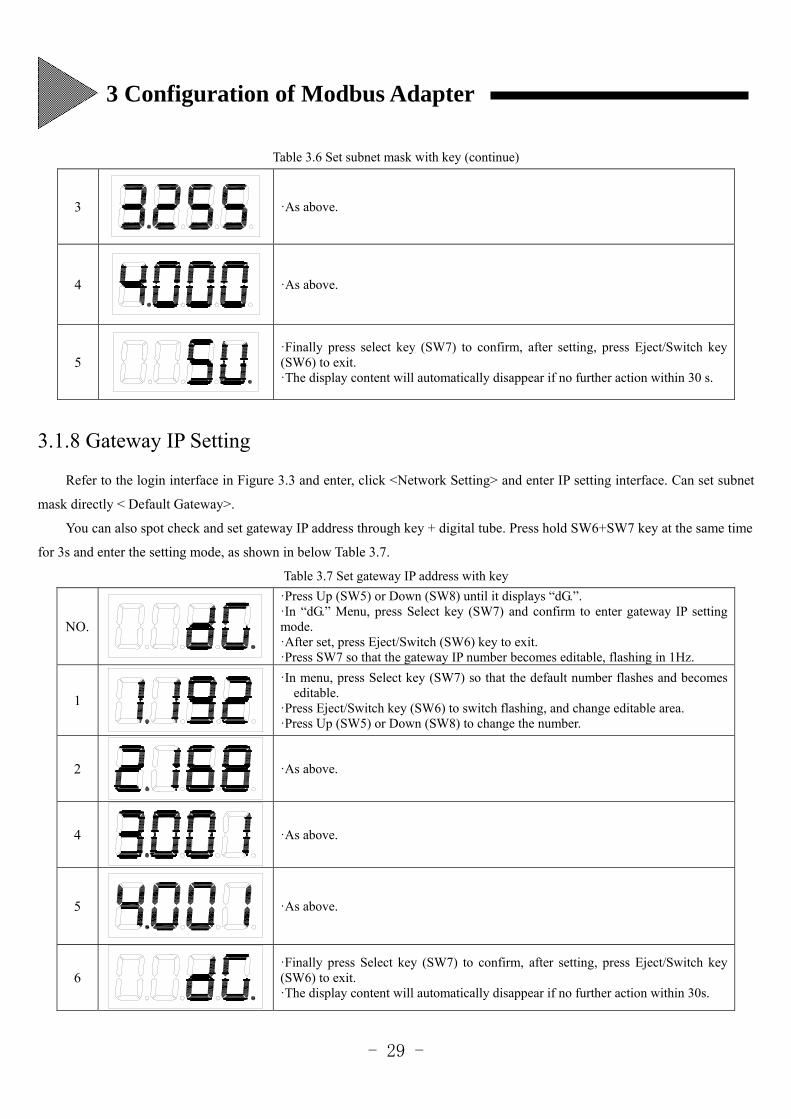
3.1.8 Gateway IP Setting
Refer to the login interface in Figure 3.3 and enter, click <Network Setting> and enter IP setting interface. Can set subnet
mask directly < Default Gateway>.
You can also spot check and set gateway IP address through key + digital tube. Press hold SW6+SW7 key at the same time
for 3s and enter the setting mode, as shown in below Table 3.7.
Table 3.7 Set gateway IP address with key
NO.
·Press Up (SW5) or Down (SW8) until it displays “dG.”. ·In “dG.” Menu, press Select key (SW7) and confirm to enter gateway IP setting mode. ·After set, press Eject/Switch (SW6) key to exit. ·Press SW7 so that the gateway IP number becomes editable, flashing in 1Hz.
1
·In menu, press Select key (SW7) so that the default number flashes and becomes editable.
·Press Eject/Switch key (SW6) to switch flashing, and change editable area. ·Press Up (SW5) or Down (SW8) to change the number.
2
·As above.
4
·As above.
5
·As above.
6
·Finally press Select key (SW7) to confirm, after setting, press Eject/Switch key (SW6) to exit. ·The display content will automatically disappear if no further action within 30s.
3 Configuration of Modbus Adapter
- 30 -
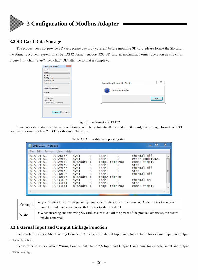
3.2 SD Card Data Storage
The product does not provide SD card, please buy it by yourself, before installing SD card, please format the SD card,
the format document system must be FAT32 format, support 32G SD card in maximum. Format operation as shown in
Figure 3.14, click “Start”, then click “Ok” after the format is completed.
Figure 3.14 Format into FAT32
Some operating state of the air conditioner will be automatically stored in SD card, the storage format is TXT document format, such as “.TXT” as shown in Table 3.8.
Table 3.8 Air conditioner operating state
Prompt sys:2 refers to No. 2 refrigerant system, addr: 1 refers to No. 1 address, outAddr:1 refers to outdoor
unit No. 1 address, error code:0x21 refers to alarm code 21.
Note When inserting and removing SD card, ensure to cut off the power of the product, otherwise, the record
maybe abnormal.
3.3 External Input and Output Linkage Function
Please refer to <2.3.2 About Wiring Connection> Table 2.2 External Input and Output Table for external input and output
linkage function.
Please refer to <2.3.2 About Wiring Connection> Table 2.6 Input and Output Using case for external input and output
linkage wiring.
3 Configuration of Modbus Adapter
- 31 -
3.4 Single Board Constant Speed Machine Login
If connect single board constant speed machine on the communication bus, please turn bit3 of the slide switch SW11to ON
before power on, otherwise, no single board constant speed machine can be connected in the whole system. Please refer to <2.4
Slide Switch Setting Method> 2.4 Slide Switch Setting Table.
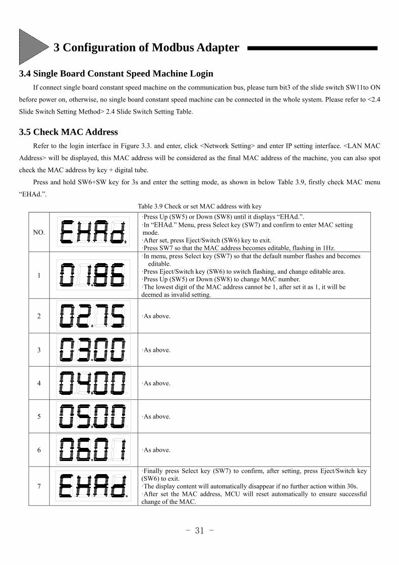
3.5 Check MAC Address
Refer to the login interface in Figure 3.3. and enter, click <Network Setting> and enter IP setting interface. <LAN MAC
Address> will be displayed, this MAC address will be considered as the final MAC address of the machine, you can also spot
check the MAC address by key + digital tube.
Press and hold SW6+SW key for 3s and enter the setting mode, as shown in below Table 3.9, firstly check MAC menu
“EHAd.”.
Table 3.9 Check or set MAC address with key
NO.
·Press Up (SW5) or Down (SW8) until it displays “EHAd.”. ·In “EHAd.” Menu, press Select key (SW7) and confirm to enter MAC setting mode. ·After set, press Eject/Switch (SW6) key to exit. ·Press SW7 so that the MAC address becomes editable, flashing in 1Hz.
1
·In menu, press Select key (SW7) so that the default number flashes and becomes editable.
·Press Eject/Switch key (SW6) to switch flashing, and change editable area. ·Press Up (SW5) or Down (SW8) to change MAC number. ·The lowest digit of the MAC address cannot be 1, after set it as 1, it will be deemed as invalid setting.
2
·As above.
3
·As above.
4
·As above.
5
·As above.
6
·As above.
7
·Finally press Select key (SW7) to confirm, after setting, press Eject/Switch key (SW6) to exit. ·The display content will automatically disappear if no further action within 30s. ·After set the MAC address, MCU will reset automatically to ensure successful change of the MAC.
3 Configuration of Modbus Adapter
- 32 -
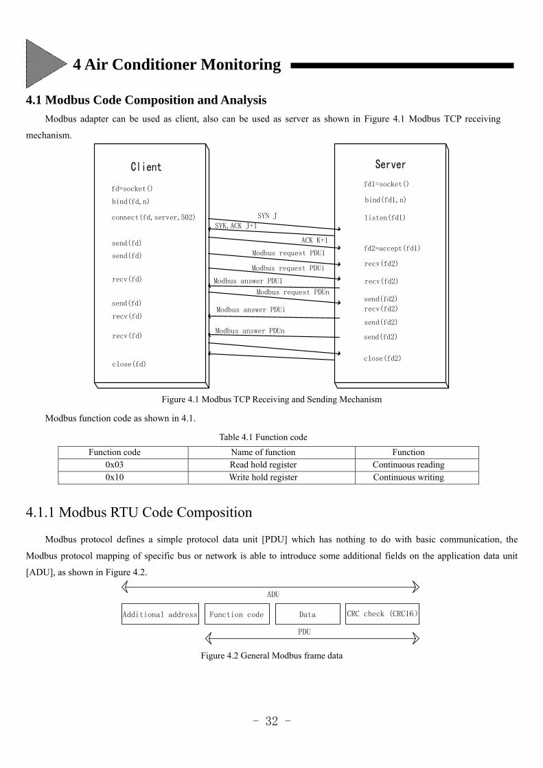
4.1 Modbus Code Composition and Analysis
Modbus adapter can be used as client, also can be used as server as shown in Figure 4.1 Modbus TCP receiving
mechanism.
Modbus answer PDUn
Modbus answer PDUi
Modbus request PDUn
Modbus answer PDU1
Modbus request PDUi
Modbus request PDU1
ACK K+1
SYK,ACK J+1
SYN J
close(fd2)
send(fd2)
send(fd2)
recv(fd2)
send(fd2)
recv(fd2)
recv(fd2)
fd2=accept(fd1)
listen(fd1)
bind(fd1,n)
fd1=socket()
recv(fd)
recv(fd)
send(fd)
send(fd)
close(fd)
recv(fd)
connect(fd,server,502)
send(fd)
bind(fd,n)
fd=socket()
Figure 4.1 Modbus TCP Receiving and Sending Mechanism
Modbus function code as shown in 4.1.
Table 4.1 Function code
Function code Name of function Function 0x03 Read hold register Continuous reading 0x10 Write hold register Continuous writing
4.1.1 Modbus RTU Code Composition
Modbus protocol defines a simple protocol data unit [PDU] which has nothing to do with basic communication, the
Modbus protocol mapping of specific bus or network is able to introduce some additional fields on the application data unit
[ADU], as shown in Figure 4.2.
ADU
PDU
CRC check (CRC16)DataFunction codeAdditional address
Figure 4.2 General Modbus frame data
4 Air Conditioner Monitoring
- 33 -
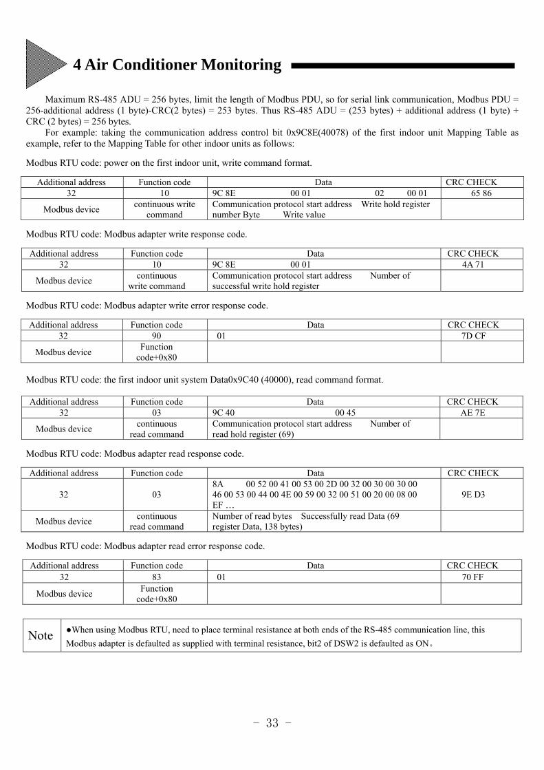
Maximum RS-485 ADU = 256 bytes, limit the length of Modbus PDU, so for serial link communication, Modbus PDU = 256-additional address (1 byte)-CRC(2 bytes) = 253 bytes. Thus RS-485 ADU = (253 bytes) + additional address (1 byte) + CRC (2 bytes) = 256 bytes.
For example: taking the communication address control bit 0x9C8E(40078) of the first indoor unit Mapping Table as example, refer to the Mapping Table for other indoor units as follows:
Modbus RTU code: power on the first indoor unit, write command format.
Additional address Function code Data CRC CHECK 32 10 9C 8E 00 01 02 00 01 65 86
Modbus device continuous write
command Communication protocol start address Write hold register number Byte Write value
Modbus RTU code: Modbus adapter write response code.
Additional address Function code Data CRC CHECK 32 10 9C 8E 00 01 4A 71
Modbus device continuous
write command Communication protocol start address Number of successful write hold register
Modbus RTU code: Modbus adapter write error response code.
Additional address Function code Data CRC CHECK 32 90 01 7D CF
Modbus device Function
code+0x80
Modbus RTU code: the first indoor unit system Data0x9C40 (40000), read command format.
Additional address Function code Data CRC CHECK 32 03 9C 40 00 45 AE 7E
Modbus device continuous
read command Communication protocol start address Number of read hold register (69)
Modbus RTU code: Modbus adapter read response code.
Additional address Function code Data CRC CHECK
32 03 8A 00 52 00 41 00 53 00 2D 00 32 00 30 00 30 00 46 00 53 00 44 00 4E 00 59 00 32 00 51 00 20 00 08 00 EF …
9E D3
Modbus device continuous
read command Number of read bytes Successfully read Data (69 register Data, 138 bytes)
Modbus RTU code: Modbus adapter read error response code.
Additional address Function code Data CRC CHECK 32 83 01 70 FF
Modbus device Function
code+0x80
Note When using Modbus RTU, need to place terminal resistance at both ends of the RS-485 communication line, this
Modbus adapter is defaulted as supplied with terminal resistance, bit2 of DSW2 is defaulted as ON。
4 Air Conditioner Monitoring
- 34 -
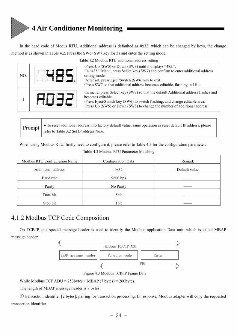
In the head code of Modus RTU, Additional address is defaulted as 0x32, which can be changed by keys, the change
method is as shown in Table 4.2. Press the SW6+SW7 key for 3s and enter the setting mode.
Table 4.2 Modbus RTU additional address setting
NO.
·Press Up (SW5) or Down (SW8) until it displays “485.”. ·In “485.” Menu, press Select key (SW7) and confirm to enter additional address setting mode. ·After set, press Eject/Switch (SW6) key to exit. ·Press SW7 so that additional address becomes editable, flashing in 1Hz.
1
·In menu, press Select key (SW7) so that the default Additional address flashes and becomes editable. ·Press Eject/Switch key (SW6) to switch flashing, and change editable area. ·Press Up (SW5) or Down (SW8) to change the number of additional address.
Prompt To reset additional address into factory default value, same operation as reset default IP address, please
refer to Table 3.2 Set IP address No.6.
When using Modbus RTU, firstly need to configure it, please refer to Table 4.3 for the configuration parameter.
Table 4.3 Modbus RTU Parameter Matching
Modbus RTU Configuration Name Configuration Data Remark
Additional address 0x32 Default value
Baud rate 9600 bps ——
Parity No Parity ——
Data bit 8bit ——
Stop bit 1bit ——
4.1.2 Modbus TCP Code Composition
On TCP/IP, one special message header is used to identify the Modbus application Data unit, which is called MBAP
message header.
Modbus TCP/IP ADU
PDU
DataFunction codeMBAP message header
Figure 4.3 Modbus TCP/IP Frame Data
While Modbus TCP ADU = 253bytes + MBAP (7 bytes) = 260bytes.
The length of MBAP message header is 7 bytes:
①Transaction identifier [2 bytes]: pairing for transaction processing. In response, Modbus adapter will copy the requested
transaction identifier.
4 Air Conditioner Monitoring
- 35 -
② Protocol identifier [2 bytes]: used for multiplexer in the system, 0 at Modbus protocol.
③ Length [2 bytes]: length field is the number of bytes in the continuation field, including unit identifier and Data field.
④ Unit identifier [1 byte]: this field is used for router selection in the system.
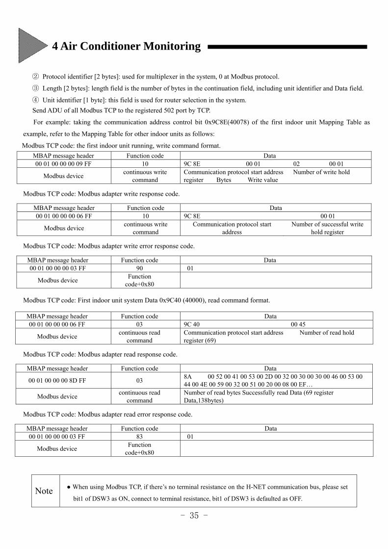
Send ADU of all Modbus TCP to the registered 502 port by TCP.
For example: taking the communication address control bit 0x9C8E(40078) of the first indoor unit Mapping Table as
example, refer to the Mapping Table for other indoor units as follows:
Modbus TCP code: the first indoor unit running, write command format.
MBAP message header Function code Data 00 01 00 00 00 09 FF 10 9C 8E 00 01 02 00 01
Modbus device continuous write
command Communication protocol start address Number of write hold register Bytes Write value
Modbus TCP code: Modbus adapter write response code.
MBAP message header Function code Data 00 01 00 00 00 06 FF 10 9C 8E 00 01
Modbus device continuous write
command Communication protocol start
address Number of successful write
hold register
Modbus TCP code: Modbus adapter write error response code.
MBAP message header Function code Data 00 01 00 00 00 03 FF 90 01
Modbus device Function
code+0x80
Modbus TCP code: First indoor unit system Data 0x9C40 (40000), read command format.
MBAP message header Function code Data 00 01 00 00 00 06 FF 03 9C 40 00 45
Modbus device continuous read
command Communication protocol start address Number of read hold register (69)
Modbus TCP code: Modbus adapter read response code.
MBAP message header Function code Data
00 01 00 00 00 8D FF 03 8A 00 52 00 41 00 53 00 2D 00 32 00 30 00 30 00 46 00 53 00 44 00 4E 00 59 00 32 00 51 00 20 00 08 00 EF…
Modbus device continuous read
command Number of read bytes Successfully read Data (69 register Data,138bytes)
Modbus TCP code: Modbus adapter read error response code.
MBAP message header Function code Data 00 01 00 00 00 03 FF 83 01
Modbus device Function
code+0x80
Note
When using Modbus TCP, if there’s no terminal resistance on the H-NET communication bus, please set
bit1 of DSW3 as ON, connect to terminal resistance, bit1 of DSW3 is defaulted as OFF.
4 Air Conditioner Monitoring
- 36 -
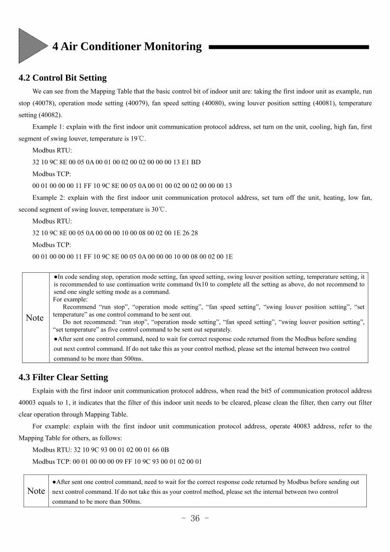
4.2 Control Bit Setting
We can see from the Mapping Table that the basic control bit of indoor unit are: taking the first indoor unit as example, run
stop (40078), operation mode setting (40079), fan speed setting (40080), swing louver position setting (40081), temperature
setting (40082).
Example 1: explain with the first indoor unit communication protocol address, set turn on the unit, cooling, high fan, first
segment of swing louver, temperature is 19.
Modbus RTU:
32 10 9C 8E 00 05 0A 00 01 00 02 00 02 00 00 00 13 E1 BD
Modbus TCP:
00 01 00 00 00 11 FF 10 9C 8E 00 05 0A 00 01 00 02 00 02 00 00 00 13
Example 2: explain with the first indoor unit communication protocol address, set turn off the unit, heating, low fan,
second segment of swing louver, temperature is 30.
Modbus RTU:
32 10 9C 8E 00 05 0A 00 00 00 10 00 08 00 02 00 1E 26 28
Modbus TCP:
00 01 00 00 00 11 FF 10 9C 8E 00 05 0A 00 00 00 10 00 08 00 02 00 1E
4.3 Filter Clear Setting
Explain with the first indoor unit communication protocol address, when read the bit5 of communication protocol address
40003 equals to 1, it indicates that the filter of this indoor unit needs to be cleared, please clean the filter, then carry out filter
clear operation through Mapping Table.
For example: explain with the first indoor unit communication protocol address, operate 40083 address, refer to the
Mapping Table for others, as follows:
Modbus RTU: 32 10 9C 93 00 01 02 00 01 66 0B
Modbus TCP: 00 01 00 00 00 09 FF 10 9C 93 00 01 02 00 01
Note
In code sending stop, operation mode setting, fan speed setting, swing louver position setting, temperature setting, it is recommended to use continuation write command 0x10 to complete all the setting as above, do not recommend to send one single setting mode as a command. For example:
Recommend “run stop”, “operation mode setting”, “fan speed setting”, “swing louver position setting”, “set temperature” as one control command to be sent out.
Do not recommend: “run stop”, “operation mode setting”, “fan speed setting”, “swing louver position setting”, “set temperature” as five control command to be sent out separately.
After sent one control command, need to wait for correct response code returned from the Modbus before sending
out next control command. If do not take this as your control method, please set the internal between two control
command to be more than 500ms.
Note
After sent one control command, need to wait for the correct response code returned by Modbus before sending out
next control command. If do not take this as your control method, please set the internal between two control
command to be more than 500ms.
4 Air Conditioner Monitoring
- 37 -
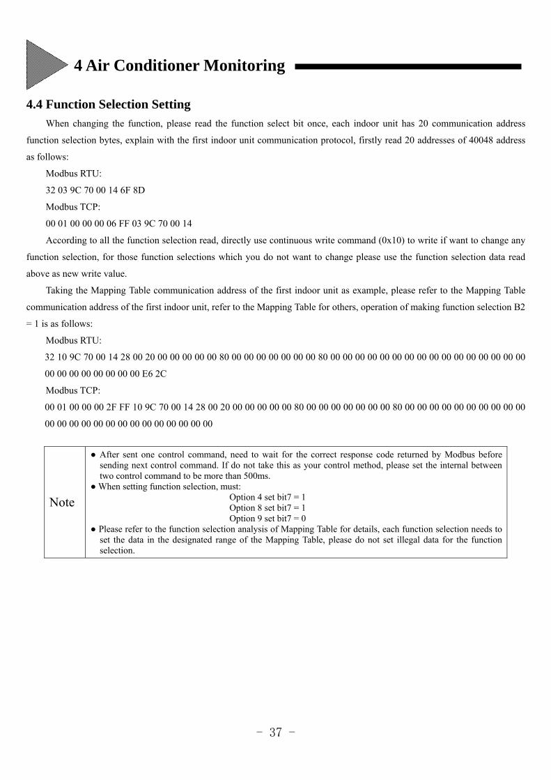
4.4 Function Selection Setting
When changing the function, please read the function select bit once, each indoor unit has 20 communication address
function selection bytes, explain with the first indoor unit communication protocol, firstly read 20 addresses of 40048 address
as follows:
Modbus RTU:
32 03 9C 70 00 14 6F 8D
Modbus TCP:
00 01 00 00 00 06 FF 03 9C 70 00 14
According to all the function selection read, directly use continuous write command (0x10) to write if want to change any
function selection, for those function selections which you do not want to change please use the function selection data read
above as new write value.
Taking the Mapping Table communication address of the first indoor unit as example, please refer to the Mapping Table
communication address of the first indoor unit, refer to the Mapping Table for others, operation of making function selection B2
= 1 is as follows:
Modbus RTU:
32 10 9C 70 00 14 28 00 20 00 00 00 00 00 80 00 00 00 00 00 00 00 80 00 00 00 00 00 00 00 00 00 00 00 00 00 00 00 00
00 00 00 00 00 00 00 00 E6 2C
Modbus TCP:
00 01 00 00 00 2F FF 10 9C 70 00 14 28 00 20 00 00 00 00 00 80 00 00 00 00 00 00 00 80 00 00 00 00 00 00 00 00 00 00
00 00 00 00 00 00 00 00 00 00 00 00 00 00
Note
After sent one control command, need to wait for the correct response code returned by Modbus before sending next control command. If do not take this as your control method, please set the internal between two control command to be more than 500ms.
When setting function selection, must: Option 4 set bit7 = 1
Option 8 set bit7 = 1 Option 9 set bit7 = 0
Please refer to the function selection analysis of Mapping Table for details, each function selection needs to set the data in the designated range of the Mapping Table, please do not set illegal data for the function selection.
4 Air Conditioner Monitoring
- 38 -
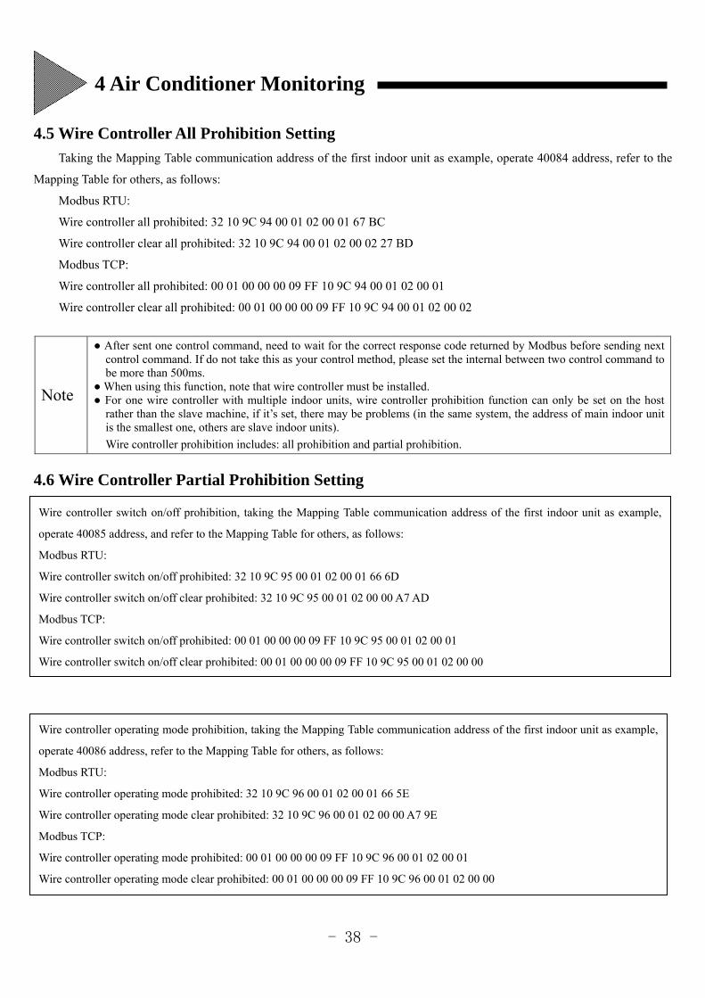
4.5 Wire Controller All Prohibition Setting
Taking the Mapping Table communication address of the first indoor unit as example, operate 40084 address, refer to the
Mapping Table for others, as follows:
Modbus RTU:
Wire controller all prohibited: 32 10 9C 94 00 01 02 00 01 67 BC
Wire controller clear all prohibited: 32 10 9C 94 00 01 02 00 02 27 BD
Modbus TCP:
Wire controller all prohibited: 00 01 00 00 00 09 FF 10 9C 94 00 01 02 00 01
Wire controller clear all prohibited: 00 01 00 00 00 09 FF 10 9C 94 00 01 02 00 02
4.6 Wire Controller Partial Prohibition Setting
Note
After sent one control command, need to wait for the correct response code returned by Modbus before sending next control command. If do not take this as your control method, please set the internal between two control command to be more than 500ms.
When using this function, note that wire controller must be installed. For one wire controller with multiple indoor units, wire controller prohibition function can only be set on the host
rather than the slave machine, if it’s set, there may be problems (in the same system, the address of main indoor unit is the smallest one, others are slave indoor units).
Wire controller prohibition includes: all prohibition and partial prohibition.
Wire controller switch on/off prohibition, taking the Mapping Table communication address of the first indoor unit as example,
operate 40085 address, and refer to the Mapping Table for others, as follows:
Modbus RTU:
Wire controller switch on/off prohibited: 32 10 9C 95 00 01 02 00 01 66 6D
Wire controller switch on/off clear prohibited: 32 10 9C 95 00 01 02 00 00 A7 AD
Modbus TCP:
Wire controller switch on/off prohibited: 00 01 00 00 00 09 FF 10 9C 95 00 01 02 00 01
Wire controller switch on/off clear prohibited: 00 01 00 00 00 09 FF 10 9C 95 00 01 02 00 00
Wire controller operating mode prohibition, taking the Mapping Table communication address of the first indoor unit as example,
operate 40086 address, refer to the Mapping Table for others, as follows:
Modbus RTU:
Wire controller operating mode prohibited: 32 10 9C 96 00 01 02 00 01 66 5E
Wire controller operating mode clear prohibited: 32 10 9C 96 00 01 02 00 00 A7 9E
Modbus TCP:
Wire controller operating mode prohibited: 00 01 00 00 00 09 FF 10 9C 96 00 01 02 00 01
Wire controller operating mode clear prohibited: 00 01 00 00 00 09 FF 10 9C 96 00 01 02 00 00
4 Air Conditioner Monitoring
- 39 -
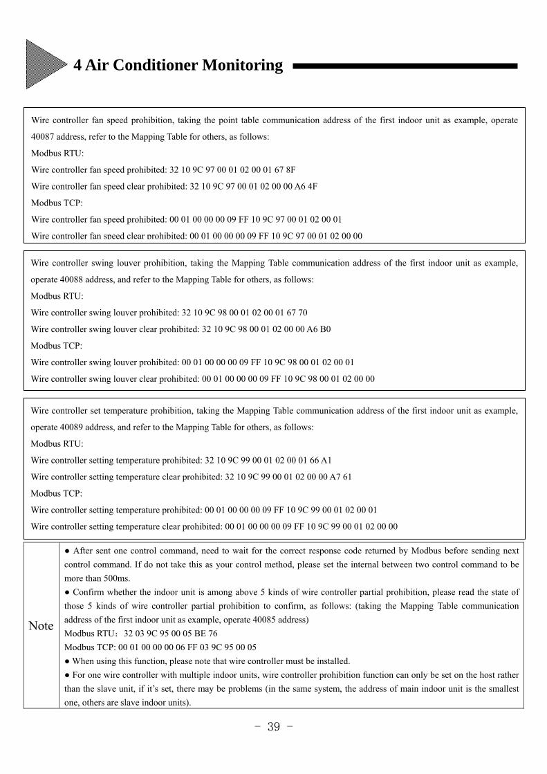
Note
After sent one control command, need to wait for the correct response code returned by Modbus before sending next
control command. If do not take this as your control method, please set the internal between two control command to be
more than 500ms.
Confirm whether the indoor unit is among above 5 kinds of wire controller partial prohibition, please read the state of
those 5 kinds of wire controller partial prohibition to confirm, as follows: (taking the Mapping Table communication
address of the first indoor unit as example, operate 40085 address)
Modbus RTU:32 03 9C 95 00 05 BE 76
Modbus TCP: 00 01 00 00 00 06 FF 03 9C 95 00 05
When using this function, please note that wire controller must be installed.
For one wire controller with multiple indoor units, wire controller prohibition function can only be set on the host rather
than the slave unit, if it’s set, there may be problems (in the same system, the address of main indoor unit is the smallest
one, others are slave indoor units).
Wire controller fan speed prohibition, taking the point table communication address of the first indoor unit as example, operate
40087 address, refer to the Mapping Table for others, as follows:
Modbus RTU:
Wire controller fan speed prohibited: 32 10 9C 97 00 01 02 00 01 67 8F
Wire controller fan speed clear prohibited: 32 10 9C 97 00 01 02 00 00 A6 4F
Modbus TCP:
Wire controller fan speed prohibited: 00 01 00 00 00 09 FF 10 9C 97 00 01 02 00 01
Wire controller fan speed clear prohibited: 00 01 00 00 00 09 FF 10 9C 97 00 01 02 00 00
Wire controller swing louver prohibition, taking the Mapping Table communication address of the first indoor unit as example,
operate 40088 address, and refer to the Mapping Table for others, as follows:
Modbus RTU:
Wire controller swing louver prohibited: 32 10 9C 98 00 01 02 00 01 67 70
Wire controller swing louver clear prohibited: 32 10 9C 98 00 01 02 00 00 A6 B0
Modbus TCP:
Wire controller swing louver prohibited: 00 01 00 00 00 09 FF 10 9C 98 00 01 02 00 01
Wire controller swing louver clear prohibited: 00 01 00 00 00 09 FF 10 9C 98 00 01 02 00 00
Wire controller set temperature prohibition, taking the Mapping Table communication address of the first indoor unit as example,
operate 40089 address, and refer to the Mapping Table for others, as follows:
Modbus RTU:
Wire controller setting temperature prohibited: 32 10 9C 99 00 01 02 00 01 66 A1
Wire controller setting temperature clear prohibited: 32 10 9C 99 00 01 02 00 00 A7 61
Modbus TCP:
Wire controller setting temperature prohibited: 00 01 00 00 00 09 FF 10 9C 99 00 01 02 00 01
Wire controller setting temperature clear prohibited: 00 01 00 00 00 09 FF 10 9C 99 00 01 02 00 00
4 Air Conditioner Monitoring
- 40 -
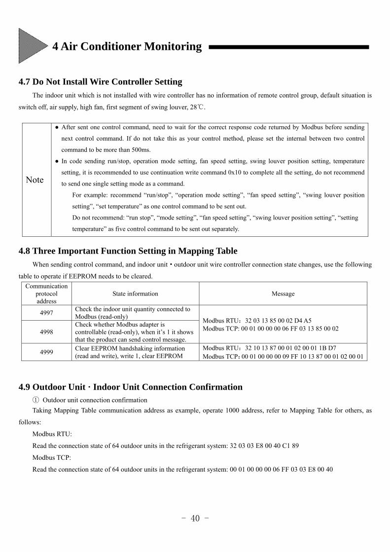
4.7 Do Not Install Wire Controller Setting
The indoor unit which is not installed with wire controller has no information of remote control group, default situation is
switch off, air supply, high fan, first segment of swing louver, 28.
4.8 Three Important Function Setting in Mapping Table
When sending control command, and indoor unit·outdoor unit wire controller connection state changes, use the following
table to operate if EEPROM needs to be cleared.
Communication protocol address
State information Message
4997 Check the indoor unit quantity connected to Modbus (read-only)
Modbus RTU:32 03 13 85 00 02 D4 A5 Modbus TCP: 00 01 00 00 00 06 FF 03 13 85 00 02 4998
Check whether Modbus adapter is controllable (read-only), when it’s 1 it shows that the product can send control message.
4999 Clear EEPROM handshaking information (read and write), write 1, clear EEPROM
Modbus RTU:32 10 13 87 00 01 02 00 01 1B D7 Modbus TCP:00 01 00 00 00 09 FF 10 13 87 00 01 02 00 01
4.9 Outdoor Unit · Indoor Unit Connection Confirmation ① Outdoor unit connection confirmation
Taking Mapping Table communication address as example, operate 1000 address, refer to Mapping Table for others, as
follows:
Modbus RTU:
Read the connection state of 64 outdoor units in the refrigerant system: 32 03 03 E8 00 40 C1 89
Modbus TCP:
Read the connection state of 64 outdoor units in the refrigerant system: 00 01 00 00 00 06 FF 03 03 E8 00 40
Note
After sent one control command, need to wait for the correct response code returned by Modbus before sending
next control command. If do not take this as your control method, please set the internal between two control
command to be more than 500ms.
In code sending run/stop, operation mode setting, fan speed setting, swing louver position setting, temperature
setting, it is recommended to use continuation write command 0x10 to complete all the setting, do not recommend
to send one single setting mode as a command.
For example: recommend “run/stop”, “operation mode setting”, “fan speed setting”, “swing louver position
setting”, “set temperature” as one control command to be sent out.
Do not recommend: “run stop”, “mode setting”, “fan speed setting”, “swing louver position setting”, “setting
temperature” as five control command to be sent out separately.
4 Air Conditioner Monitoring
- 41 -
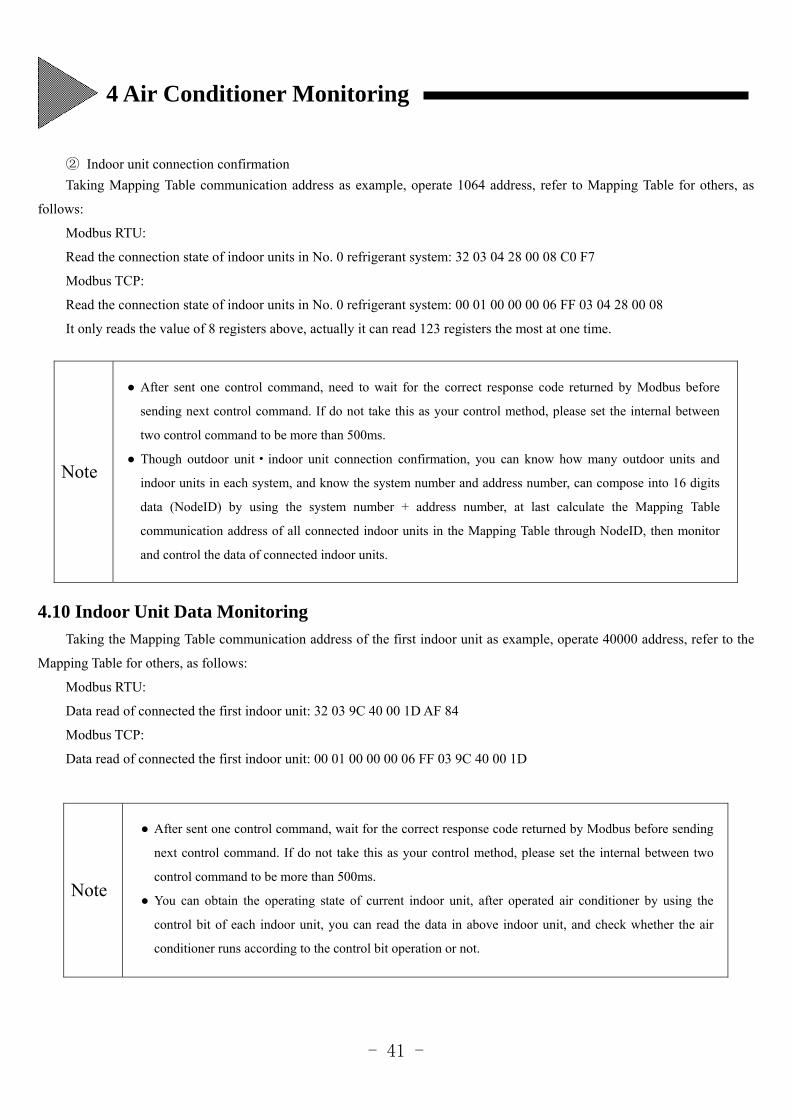
② Indoor unit connection confirmation
Taking Mapping Table communication address as example, operate 1064 address, refer to Mapping Table for others, as
follows:
Modbus RTU:
Read the connection state of indoor units in No. 0 refrigerant system: 32 03 04 28 00 08 C0 F7
Modbus TCP:
Read the connection state of indoor units in No. 0 refrigerant system: 00 01 00 00 00 06 FF 03 04 28 00 08
It only reads the value of 8 registers above, actually it can read 123 registers the most at one time.
4.10 Indoor Unit Data Monitoring
Taking the Mapping Table communication address of the first indoor unit as example, operate 40000 address, refer to the
Mapping Table for others, as follows:
Modbus RTU:
Data read of connected the first indoor unit: 32 03 9C 40 00 1D AF 84
Modbus TCP:
Data read of connected the first indoor unit: 00 01 00 00 00 06 FF 03 9C 40 00 1D
Note
Note
After sent one control command, need to wait for the correct response code returned by Modbus before
sending next control command. If do not take this as your control method, please set the internal between
two control command to be more than 500ms.
Though outdoor unit·indoor unit connection confirmation, you can know how many outdoor units and
indoor units in each system, and know the system number and address number, can compose into 16 digits
data (NodeID) by using the system number + address number, at last calculate the Mapping Table
communication address of all connected indoor units in the Mapping Table through NodeID, then monitor
and control the data of connected indoor units.
After sent one control command, wait for the correct response code returned by Modbus before sending
next control command. If do not take this as your control method, please set the internal between two
control command to be more than 500ms.
You can obtain the operating state of current indoor unit, after operated air conditioner by using the
control bit of each indoor unit, you can read the data in above indoor unit, and check whether the air
conditioner runs according to the control bit operation or not.
4 Air Conditioner Monitoring
- 42 -
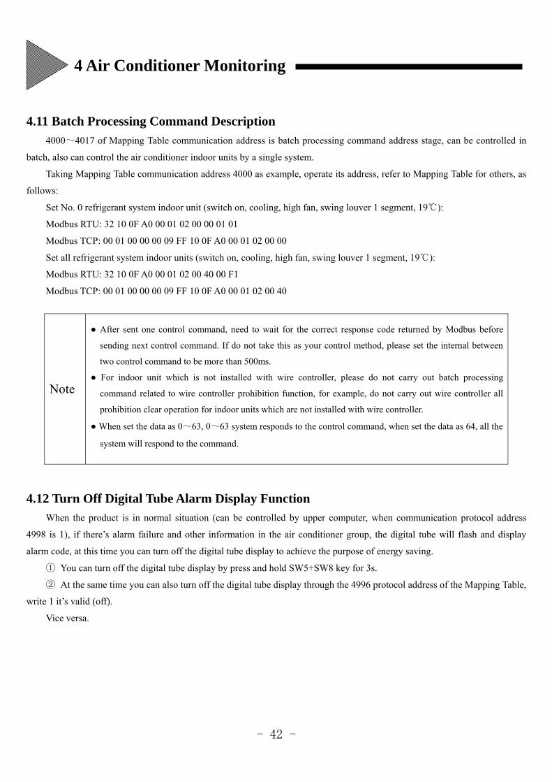
4.11 Batch Processing Command Description
4000~4017 of Mapping Table communication address is batch processing command address stage, can be controlled in
batch, also can control the air conditioner indoor units by a single system.
Taking Mapping Table communication address 4000 as example, operate its address, refer to Mapping Table for others, as
follows:
Set No. 0 refrigerant system indoor unit (switch on, cooling, high fan, swing louver 1 segment, 19):
Modbus RTU: 32 10 0F A0 00 01 02 00 00 01 01
Modbus TCP: 00 01 00 00 00 09 FF 10 0F A0 00 01 02 00 00
Set all refrigerant system indoor units (switch on, cooling, high fan, swing louver 1 segment, 19):
Modbus RTU: 32 10 0F A0 00 01 02 00 40 00 F1
Modbus TCP: 00 01 00 00 00 09 FF 10 0F A0 00 01 02 00 40
4.12 Turn Off Digital Tube Alarm Display Function
When the product is in normal situation (can be controlled by upper computer, when communication protocol address
4998 is 1), if there’s alarm failure and other information in the air conditioner group, the digital tube will flash and display
alarm code, at this time you can turn off the digital tube display to achieve the purpose of energy saving.
① You can turn off the digital tube display by press and hold SW5+SW8 key for 3s.
② At the same time you can also turn off the digital tube display through the 4996 protocol address of the Mapping Table,
write 1 it’s valid (off).
Vice versa.
Note
After sent one control command, need to wait for the correct response code returned by Modbus before
sending next control command. If do not take this as your control method, please set the internal between
two control command to be more than 500ms.
For indoor unit which is not installed with wire controller, please do not carry out batch processing
command related to wire controller prohibition function, for example, do not carry out wire controller all
prohibition clear operation for indoor units which are not installed with wire controller.
When set the data as 0~63, 0~63 system responds to the control command, when set the data as 64, all the
system will respond to the command.
4 Air Conditioner Monitoring
- 43 -
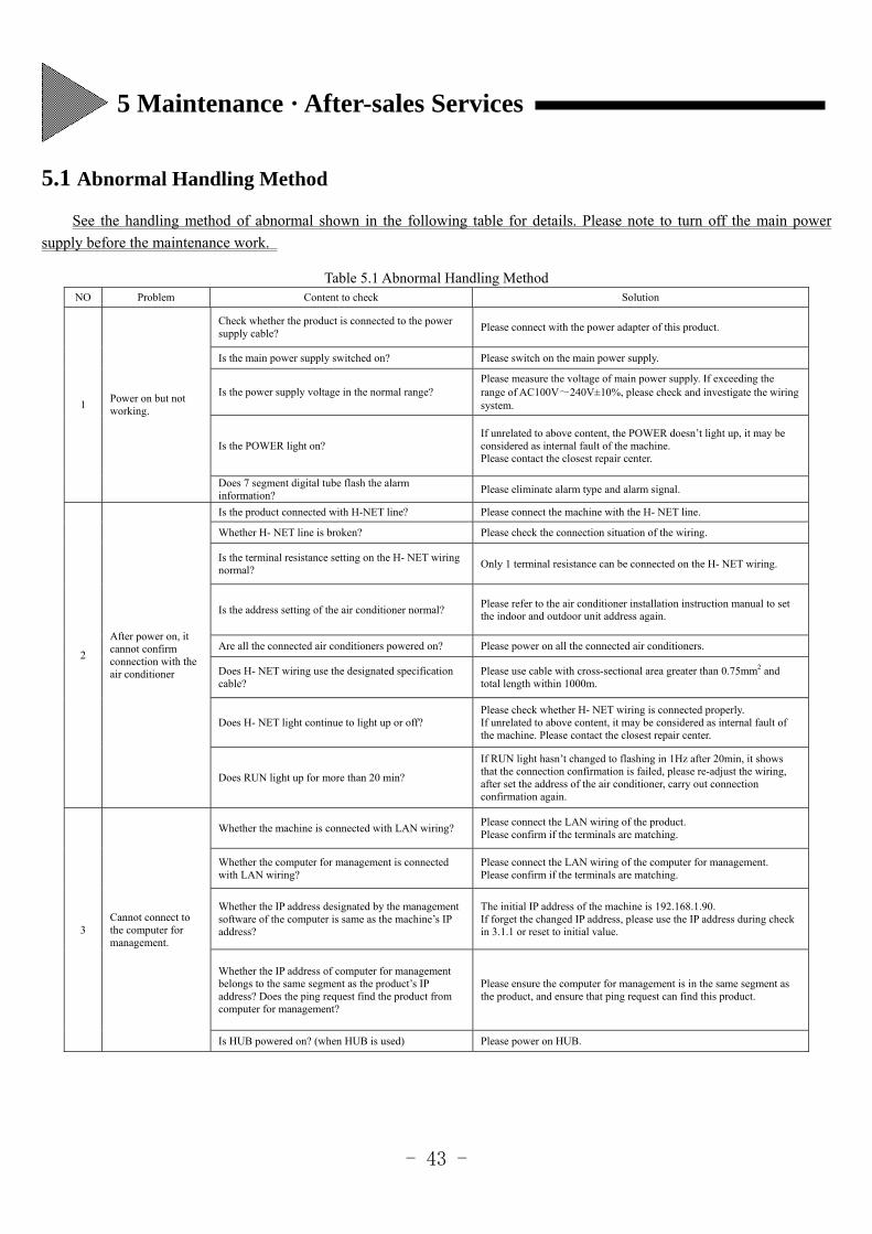
5.1 Abnormal Handling Method
See the handling method of abnormal shown in the following table for details. Please note to turn off the main power
supply before the maintenance work.
Table 5.1 Abnormal Handling Method NO Problem Content to check Solution
1 Power on but not working.
Check whether the product is connected to the power supply cable?
Please connect with the power adapter of this product.
Is the main power supply switched on? Please switch on the main power supply.
Is the power supply voltage in the normal range? Please measure the voltage of main power supply. If exceeding the range of AC100V~240V±10%, please check and investigate the wiring system.
Is the POWER light on? If unrelated to above content, the POWER doesn’t light up, it may be considered as internal fault of the machine. Please contact the closest repair center.
Does 7 segment digital tube flash the alarm information?
Please eliminate alarm type and alarm signal.
2
After power on, it cannot confirm connection with the air conditioner
Is the product connected with H-NET line? Please connect the machine with the H- NET line.
Whether H- NET line is broken? Please check the connection situation of the wiring.
Is the terminal resistance setting on the H- NET wiring normal?
Only 1 terminal resistance can be connected on the H- NET wiring.
Is the address setting of the air conditioner normal? Please refer to the air conditioner installation instruction manual to set the indoor and outdoor unit address again.
Are all the connected air conditioners powered on? Please power on all the connected air conditioners.
Does H- NET wiring use the designated specification cable?
Please use cable with cross-sectional area greater than 0.75mm2 and total length within 1000m.
Does H- NET light continue to light up or off? Please check whether H- NET wiring is connected properly. If unrelated to above content, it may be considered as internal fault of the machine. Please contact the closest repair center.
Does RUN light up for more than 20 min?
If RUN light hasn’t changed to flashing in 1Hz after 20min, it shows that the connection confirmation is failed, please re-adjust the wiring, after set the address of the air conditioner, carry out connection confirmation again.
3 Cannot connect to the computer for management.
Whether the machine is connected with LAN wiring? Please connect the LAN wiring of the product. Please confirm if the terminals are matching.
Whether the computer for management is connected with LAN wiring?
Please connect the LAN wiring of the computer for management. Please confirm if the terminals are matching.
Whether the IP address designated by the management software of the computer is same as the machine’s IP address?
The initial IP address of the machine is 192.168.1.90. If forget the changed IP address, please use the IP address during check in 3.1.1 or reset to initial value.
Whether the IP address of computer for management belongs to the same segment as the product’s IP address? Does the ping request find the product from computer for management?
Please ensure the computer for management is in the same segment as the product, and ensure that ping request can find this product.
Is HUB powered on? (when HUB is used) Please power on HUB.
5 Maintenance · After-sales Services
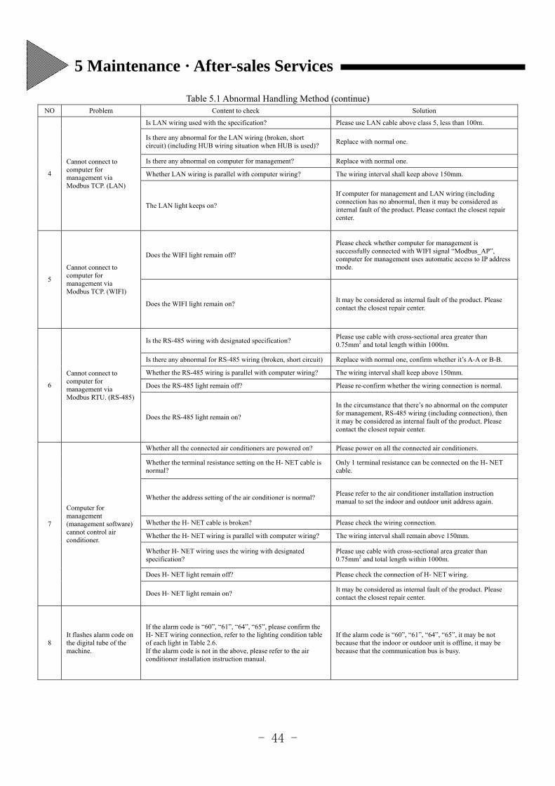
- 44 -
Table 5.1 Abnormal Handling Method (continue) NO Problem Content to check Solution
4
Cannot connect to computer for management via Modbus TCP. (LAN)
Is LAN wiring used with the specification? Please use LAN cable above class 5, less than 100m.
Is there any abnormal for the LAN wiring (broken, short circuit) (including HUB wiring situation when HUB is used)?
Replace with normal one.
Is there any abnormal on computer for management? Replace with normal one.
Whether LAN wiring is parallel with computer wiring? The wiring interval shall keep above 150mm.
The LAN light keeps on?
If computer for management and LAN wiring (including connection has no abnormal, then it may be considered as internal fault of the product. Please contact the closest repair center.
5
Cannot connect to computer for management via Modbus TCP. (WIFI)
Does the WIFI light remain off?
Please check whether computer for management is successfully connected with WIFI signal “Modbus_AP”, computer for management uses automatic access to IP address mode.
Does the WIFI light remain on? It may be considered as internal fault of the product. Please contact the closest repair center.
6
Cannot connect to computer for management via Modbus RTU. (RS-485)
Is the RS-485 wiring with designated specification? Please use cable with cross-sectional area greater than 0.75mm2 and total length within 1000m.
Is there any abnormal for RS-485 wiring (broken, short circuit) Replace with normal one, confirm whether it’s A-A or B-B.
Whether the RS-485 wiring is parallel with computer wiring? The wiring interval shall keep above 150mm.
Does the RS-485 light remain off? Please re-confirm whether the wiring connection is normal.
Does the RS-485 light remain on?
In the circumstance that there’s no abnormal on the computer for management, RS-485 wiring (including connection), then it may be considered as internal fault of the product. Please contact the closest repair center.
7
Computer for management (management software) cannot control air conditioner.
Whether all the connected air conditioners are powered on? Please power on all the connected air conditioners.
Whether the terminal resistance setting on the H- NET cable is normal?
Only 1 terminal resistance can be connected on the H- NET cable.
Whether the address setting of the air conditioner is normal? Please refer to the air conditioner installation instruction manual to set the indoor and outdoor unit address again.
Whether the H- NET cable is broken? Please check the wiring connection.
Whether the H- NET wiring is parallel with computer wiring? The wiring interval shall remain above 150mm.
Whether H- NET wiring uses the wiring with designated specification?
Please use cable with cross-sectional area greater than 0.75mm2 and total length within 1000m.
Does H- NET light remain off? Please check the connection of H- NET wiring.
Does H- NET light remain on? It may be considered as internal fault of the product. Please contact the closest repair center.
8 It flashes alarm code on the digital tube of the machine.
If the alarm code is “60”, “61”, “64”, “65”, please confirm the H- NET wiring connection, refer to the lighting condition table of each light in Table 2.6. If the alarm code is not in the above, please refer to the air conditioner installation instruction manual.
If the alarm code is “60”, “61”, “64”, “65”, it may be not because that the indoor or outdoor unit is offline, it may be because that the communication bus is busy.
5 Maintenance · After-sales Services
- 45 -
5.2 Regular Check
To ensure the normal operation of the air conditioning system including this system, please regularly check the following
content.
(1) Surrounding environment
Is the product temperature changed very high?
Does the surface temperature of the product power adapter become very high?
Is there dust, dirt, line debris, etc. in the product?
(2) Display relationship
Is the POWER light on?
does the RUN light flash?
Have the state indicating lights (H-NET, Modbus, WIFI, RS-485) been off?
Is the 7 segment digital tube often in off state?
(3) Installation and connection
Are the installation screws of the product and screws to fix the top cover loose?
Is the wiring continuous state normal?
Note
Please do not use thinner and the like for cleaning, it may cause surface discoloration, resin melt.
Please wipe with a soft cloth to clean.
Do not use wet cloth to wipe, otherwise, it may cause failure.
5 Maintenance · After-sales Services
- 46 -
1. Notes and attentions of control state checking
The control bit of switch on/off, operation mode setting, fan speed setting, swing louver setting, temperature setting, filter reset
setting is defaulted as 255, it will return to 255 after successfully sent control commands. At this time if you want to check the
running state of indoor unit, please refer to 4.10 indoor unit data monitoring to check whether it runs as per control command, if wire
controller all prohibited, or wire controller partial prohibited command setting, you can check its corresponding Mapping Table
position.
2. Notes and attentions of LAN WEB
When setting subnet mask through LAN WEB server login, please do not set illegal subnet mask, i.e. 255.255.255.0 is legal,
255.255.255.1 is illegal, after setting, it will be not able to connect even if the network of Modbus adapter and computer for
management are in the same IP segment.
Solution: clear Ethernet EEPROM data, factory reset IP setting, please refer to Table 3.2 Set IP address with key.
3. Notes and attentions of auto fan speed setting Only K3 indoor unit and DC indoor unit can be set as “Auto fan speed”, other machines cannot run auto fan speed even if it’s set.
4. Notes and attentions of AC desiccant unit
Wire controller temperature prohibition cannot be set for AC desiccant unit, please remove it as soon as possible if set.
5. Notes and attentions of one wire controller with multiple indoor units
The indoor units in the same wire controller group are working according to the same control commands, when login the wire
controller group, the product will automatically choose one indoor unit as the host, the benchmark is to select indoor unit with
smaller refrigerant system number and address number as the host. For example, indoor unit with swing louver and indoor unit
without swing louver are in the same wire controller group, to control the indoor unit with swing louver, the indoor unit with swing
louver must be set as the host, while indoor unit without swing louver as slave.
In the same system, the indoor unit with the smallest address number is the host, for example, when the host is K3 four directions,
the host can do swing louver setting, the slave with swing louver can do swing louver, the slave without swing louver cannot do
swing louver. But if the host is embedded and other machine, it does not have swing louver itself, then the host cannot do swing
louver setting, while the slave cannot do the swing louver either even if it has swing louver, the solution is to set the indoor unit with
more functions as the host.
6. Notes and attentions of being used together with other centralized controllers
When being used with other centralized controllers, do not set remote control prohibition function (all prohibition and partial
prohibition), and do not set remote control prohibition function on the centralized controller used together, if remote control
prohibition is set, it may not work properly.
7. Notes and attentions of fan speed jump and operating mode jump
Taking the first indoor unit as example, if detected any of the operation mode jump (40005 bit0~3) and fan speed jump (40006) is
bit = 1, PC cannot set corresponding operation mode and fan speed, and it cannot work even if it was set.
6 Notes and Attentions
- 47 -
8. Notes and attentions of function selection setting
To carry out function selection setting of indoor unit, the indoor unit must be stopped, if not, sometimes the setting cannot be
correctly applied.
The setting content will be different due to different functions of each unit, please refer to indoor unit installation spot checking
method for detailed information.
After carried out function selection setting related to indoor unit control, please re-connect the product and confirm (clear EEPROM
Data).
After replaced the base plate or wire controller of the indoor unit, please set again, and re-connect the product to confirm.
When being used together with other centralized controllers, after set “Cool and warm automatic function” b8, please make same
setting on the centralized controller which can set function selection.
If only connected with light receiving section, need to replace with cable wire controller temporarily.
Carry out b4 setting by the product, filter symbol must be reset, do the setting after the filter symbol of the wire controller
disappeared.
When setting function selection, please ensure to consult the service personnel of our company.
9. Notes and attentions of DC desiccant unit
“Dry 1”, “Dry 2” and “Dry 3” can only be set on DC desiccant unit, taking the first indoor unit as example, operate 40077 address to
set.
10. Notes and attentions of wire controller installation
Although wire controller is installed, and wire controller prohibition function is not set, but it shows “centralized control” on the
wire controller, which leads to that the wire controller cannot be controlled, please check whether the power supply is connected
before installation, because there’s possibility that it identifies the air conditioner which is installed with wire controller as without
wire controller installed. After connected and confirmed again, clear wire controller prohibition, reconfirm whether the “centralized
control” of wire controller is cancelled. In addition, the indoor unit which isn’t installed with wire controller will always be
controlled by the product.
For indoor unit which is installed with wire controller, if unload the wire controller in half-way, the product may be not able to
control the air conditioner properly, please connect and confirm again (clear EEPROM).
11. Notes and attentions of Modbus RTU CRC CHECK
Modbus RTU CRC check of the product shall adopt CRC16.
12. Notes and attentions of Modbus TCP connection
When using multiple computers for management to operate the same Modbus adapter, as long as one of the computer for
management disconnects, if other computers for management want to continue to send code, need to re-establish TCP connection
between the client and server.
13. Notes and attentions of connection confirmation
If the connection confirmation takes too long time, in the connection confirmation for more than 20 minutes, please use wire
controller to stop the operation of indoor unit, the time of connection confirmation can be shortened.
6 Notes and Attentions
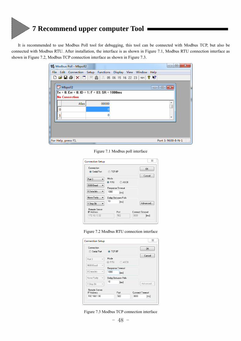
- 48 -
It is recommended to use Modbus Poll tool for debugging, this tool can be connected with Modbus TCP, but also be
connected with Modbus RTU. After installation, the interface is as shown in Figure 7.1, Modbus RTU connection interface as
shown in Figure 7.2, Modbus TCP connection interface as shown in Figure 7.3.
Figure 7.1 Modbus poll interface
Figure 7.2 Modbus RTU connection interface
Figure 7.3 Modbus TCP connection interface
7 Recommend upper computer Tool

- 49 -
集中控制区域·机组登记表(1)
Centralized Control Area · Unit Group Registration Form (1)
ID 0 1 2 3 4 5 6 7 8 9 10 11 12 13 14 15 16 17 18 19 20 21 22 23 24 25 26 27 28 29 30 31
0
1
2
3
4
5
6
7
8
9
10
11
12
13
14
15
16
17
18
19
20
21
22
23
24
25
26
27
28
29
30
31
※请在表中记录区域中标记连线的室内机情况,按系统号+地址号从小到大依次排列出来。
※Please record in the table the situation of indoor units which are marked to be connected in the area, list in turn from small to
large according to the system number + address number.

- 50 -
集中控制区域·机组登记表(2)
Centralized Control Area · Unit Group Registration Form (2)
ID 32 33 34 35 36 37 38 39 40 41 42 43 44 45 46 47 48 49 50 51 52 53 54 55 56 57 58 59 60 61 62 63
0
1
2
3
4
5
6
7
8
9
10
11
12
13
14
15
16
17
18
19
20
21
22
23
24
25
26
27
28
29
30
31
※请在表中记录区域中标记连线的室内机情况,按系统号+地址号从小到大依次排列出来。
※Please record in the table the situation of indoor units which are marked to be connected in the area, list in turn from small to
large according to the system number + address number.

- 51 -
集中控制区域·机组登记表(3)
Centralized Control Area · Unit Group Registration Form (3)
ID 0 1 2 3 4 5 6 7 8 9 10 11 12 13 14 15 16 17 18 19 20 21 22 23 24 25 26 27 28 29 30 31
32
33
34
35
36
37
38
39
40
41
42
43
44
45
46
47
48
49
50
51
52
53
54
55
56
57
58
59
60
61
62
63
※请在表中记录区域中标记连线的室内机情况,按系统号+地址号从小到大依次排列出来。
※Please record in the table the situation of indoor units which are marked to be connected in the area, list in turn from small to
large according to the system number + address number.

- 52 -
集中控制区域·机组登记表(4)
Centralized Control Area · Unit Group Registration Form (4)
ID 32 33 34 35 36 37 38 39 40 41 42 43 44 45 46 47 48 49 50 51 52 53 54 55 56 57 58 59 60 61 62 63
32
33
34
35
36
37
38
39
40
41
42
43
44
45
46
47
48
49
50
51
52
53
54
55
56
57
58
59
60
61
62
63
※请在表中记录区域中标记连线的室内机情况,按系统号+地址号从小到大依次排列出来。
※Please record in the table the situation of indoor units which are marked to be connected in the area, list in turn from small to
large according to the system number + address number.

- 53 -
集中控制区域·机组·备注登记表(1)
Centralized Control Area ·Unit Group· Note Registration Form (1)
系统号
System No
地址号
Address No
备注(房间名等)
Note (room number, etc.)
系统号
System No
地址号
Address No
备注(房间名等)
Note (room number, etc.)

- 54 -
集中控制区域·机组·备注登记表(2)
Centralized Control Area ·Unit Group· Note Registration Form (2)
系统号
System No
地址号
Address No
备注(房间名等)
Note (room number, etc.)
系统号
System No
地址号
Address No
备注(房间名等)
Note (room number, etc.)

- 55 -
集中控制区域·机组·备注登记表(3)
Centralized Control Area ·Unit Group· Note Registration Form (3)
系统号
System No
地址号
Address No
备注(房间名等)
Note (room number, etc.)
系统号
System No
地址号
Address No
备注(房间名等)
Note (room number, etc.)

- 56 -
集中控制区域·机组·备注登记表(4)
Centralized Control Area ·Unit Group· Note Registration Form (4)
系统号
System No
地址号
Address No
备注(房间名等)
Note (room number, etc.)
系统号
System No
地址号
Address No
备注(房间名等)
Note (room number, etc.)

- 57 -

- 58 -
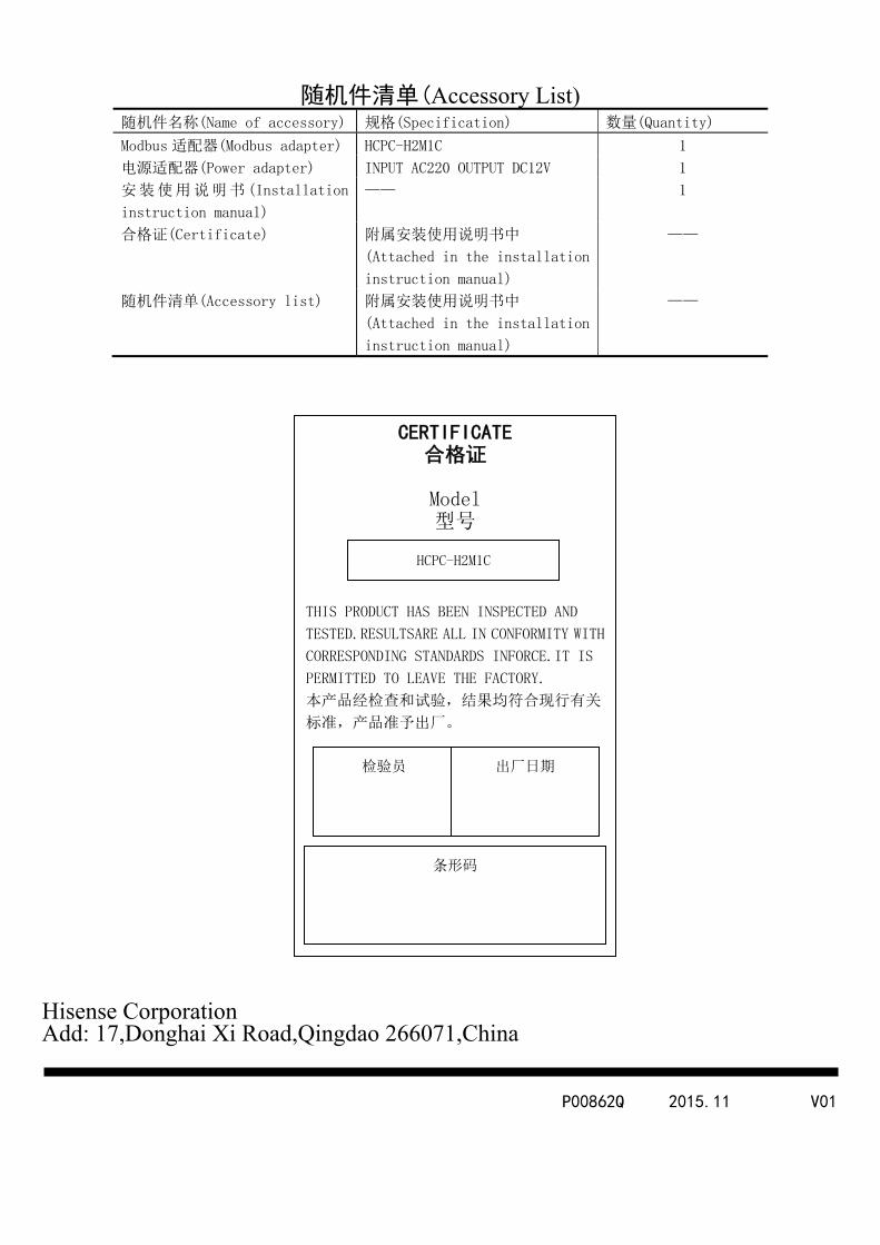
- 59 -
随机件清单(Accessory List) 随机件名称(Name of accessory) 规格(Specification) 数量(Quantity)
Modbus 适配器(Modbus adapter) HCPC-H2M1C 1
电源适配器(Power adapter) INPUT AC220 OUTPUT DC12V 1
安装使用说明书(Installation
instruction manual)
—— 1
合格证(Certificate) 附属安装使用说明书中
(Attached in the installation
instruction manual)
——
随机件清单(Accessory list) 附属安装使用说明书中
(Attached in the installation
instruction manual)
——
Hisense Corporation Add: 17,Donghai Xi Road,Qingdao 266071,China
P00862Q 2015.11 V01
CERTIFICATE 合格证
Model 型号
THIS PRODUCT HAS BEEN INSPECTED AND
TESTED.RESULTSARE ALL IN CONFORMITY WITH
CORRESPONDING STANDARDS INFORCE.IT IS
PERMITTED TO LEAVE THE FACTORY.
本产品经检查和试验,结果均符合现行有关
标准,产品准予出厂。
条形码
HCPC-H2M1C
检验员 出厂日期


![MODBUS IINDUSTRIE sWETTERSTATIONNDUSTRIE …€¦ · MODBUS rain[e]one Modbus INDUSTRY Modbus Pyranometer THP[pro] Modbus rain one Modbus IN Wiegender Nieder-schlagssensor Windrichtung](https://img.pdfslide.net/doc/110x75/5eb88fa576fba607cd617fd5/modbus-iindustrie-swetterstationndustrie-modbus-raineone-modbus-industry-modbus.jpg)