Embed Size (px)
Citation preview
A documentation by: Siemens. © Siemens AG 2011. All rights reserved.
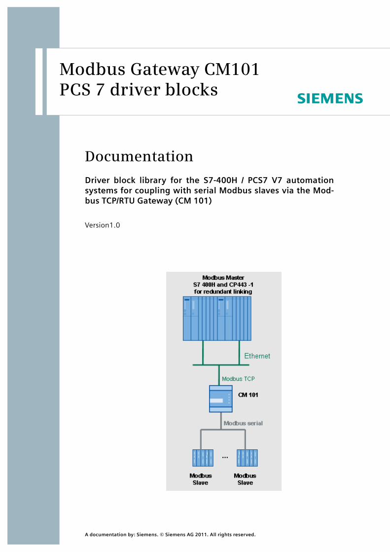
Modbus Gateway CM101 PCS 7 driver blocks
Documentation Driver block library for the S7-400H / PCS7 V7 automation systems for coupling with serial Modbus slaves via the Mod-bus TCP/RTU Gateway (CM 101)
Version1.0
A documentation by: Siemens. © Siemens AG 2011. All rights reserved.
Documentation | Modbus Gateway CM101 PCS 7 driver blocks | 2
Table of contents
1 System requirements ............................................................................. 5
1.1 License................................................................................................ 5
1.2 Software ............................................................................................. 5
1.3 Hardware ............................................................................................ 5
1.4 CM 101 - Modbus Gateway ................................................................. 5 1.4.1 General Infos ................................................................................. 5 1.4.2 Mounting ...................................................................................... 6 1.4.3 Hardware interface......................................................................... 7 1.4.4 Indicators ...................................................................................... 7 1.4.5 Configure the IP adress ................................................................... 8 1.4.6 Gateway configuration ................................................................. 10
2 General information............................................................................. 11
2.1 Step 7 block library........................................................................... 11
2.2 Supported functionalities................................................................. 11
2.3 Communication principle ................................................................. 11
2.4 Quantity structure ............................................................................ 13
2.5 Performance ..................................................................................... 13
2.6 Communication blocks used............................................................. 17
2.7 Required CP ...................................................................................... 17
3 Configuring the hardware.................................................................... 18
3.1 General configuration instructions .................................................. 18
3.2 HW Config......................................................................................... 18
3.3 NetPro-Config ................................................................................... 19
4 Description of the function blocks ....................................................... 23
4.1 MODX_COMRED – communication block.......................................... 23
A documentation by: Siemens. © Siemens AG 2011. All rights reserved.
Documentation | Modbus Gateway CM101 PCS 7 driver blocks | 3
4.1.1 Function and mode of operation ................................................... 23 4.1.2 Parameterizing and interconnecting .............................................. 23 4.1.3 Calling OBs .................................................................................. 27 4.1.4 Error handling.............................................................................. 28 4.1.5 Signaling behavior ....................................................................... 28 4.1.6 CFC block representation .............................................................. 30 4.1.7 Parameter list............................................................................... 30
4.2 MODX_WRITE - request block ........................................................... 32 4.2.1 Function and mode of operation ................................................... 32 4.2.2 Parameterizing and interconnecting .............................................. 32 4.2.3 Calling OBs .................................................................................. 33 4.2.4 Error handling.............................................................................. 33 4.2.5 Signaling behavior ....................................................................... 34 4.2.6 CFC block representation .............................................................. 34 4.2.7 Parameter list............................................................................... 34
4.3 MODX_READ - request block............................................................. 35 4.3.1 Function and mode of operation ................................................... 35 4.3.2 Parameterizing and interconnecting .............................................. 35 4.3.3 Calling OBs .................................................................................. 37 4.3.4 Error handling.............................................................................. 37 4.3.5 Signaling behavior ....................................................................... 38 4.3.6 CFC block representation .............................................................. 38 4.3.7 Parameter list............................................................................... 38
4.4 Example applications ....................................................................... 40
4.5 W1R_SCALE - Conversion block ........................................................ 44 4.5.1 Function and mode of operation ................................................... 44 4.5.2 Parameterizing and interconnecting .............................................. 44 4.5.3 Calling OBs .................................................................................. 44 4.5.4 Error handling.............................................................................. 44 4.5.5 Signaling behavior ....................................................................... 45 4.5.6 CFC block representation .............................................................. 45 4.5.7 Parameter list............................................................................... 45
A documentation by: Siemens. © Siemens AG 2011. All rights reserved.
Documentation | Modbus Gateway CM101 PCS 7 driver blocks | 4
4.6 W2R_SCALE - conversion block ......................................................... 46 4.6.1 Function and mode of operation ................................................... 46 4.6.2 Parameterizing and interconnecting .............................................. 46 4.6.3 Calling OBs .................................................................................. 46 4.6.4 Error handling.............................................................................. 46 4.6.5 Signaling behavior ....................................................................... 47 4.6.6 CFC block representation .............................................................. 47 4.6.7 Parameter list............................................................................... 47
5
A documentation by: Siemens. © Siemens AG 2011. All rights reserved.
Documentation | Modbus Gateway CM101 PCS 7 driver blocks |
1.1 License
A license is required for the driver library.
1.2 Software
The library requires PCS7 V7.1 / SIMATIC STEP7 V5.4 SP4 or higher.
1.3 Hardware
The blocks can be executed in S7-41x (non redundant) or S7-41xH CPUs with connected CP443-1 EX20.
1.4 CM 101 - Modbus Gateway
For connecting the serial modbus slaves, you need a specially for Siemens developed Modbus TCP/RTU Gateway, which is delivered by Siemens with this driver library.
A configuration program for setting the IP adress of the device is added to the setup of this library.
Please don`t update the firmware of the device with a software that is not supported by Siemens.
1.4.1 General Infos
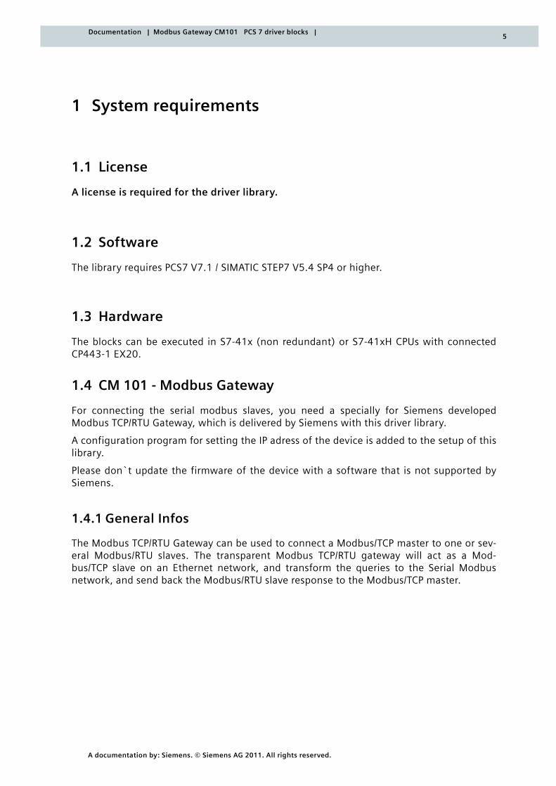
The Modbus TCP/RTU Gateway can be used to connect a Modbus/TCP master to one or sev-eral Modbus/RTU slaves. The transparent Modbus TCP/RTU gateway will act as a Mod-bus/TCP slave on an Ethernet network, and transform the queries to the Serial Modbus network, and send back the Modbus/RTU slave response to the Modbus/TCP master.
1 System requirements
6
A documentation by: Siemens. © Siemens AG 2011. All rights reserved.
Documentation | Modbus Gateway CM101 PCS 7 driver blocks |
The Modbus Gateway supports RS-232 through a 9-pole DSUB or RS-485 through the screw terminal block on the other side of the module. It supports 10/100Mbps Ethernet through a standard Ethernet connector (RJ-45). It can be configured via a web-interface or by using the “Netbiter Config” utility.
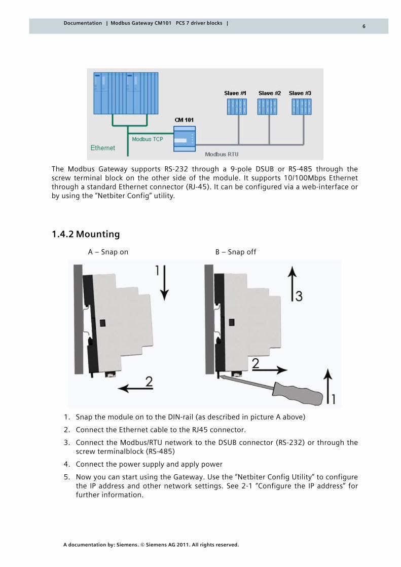
1.4.2 Mounting
A – Snap on B – Snap off
1. Snap the module on to the DIN-rail (as described in picture A above)
2. Connect the Ethernet cable to the RJ45 connector.
3. Connect the Modbus/RTU network to the DSUB connector (RS-232) or through the screw terminalblock (RS-485)
4. Connect the power supply and apply power
5. Now you can start using the Gateway. Use the “Netbiter Config Utility” to configure the IP address and other network settings. See 2-1 “Configure the IP address” for further information.
7
A documentation by: Siemens. © Siemens AG 2011. All rights reserved.
Documentation | Modbus Gateway CM101 PCS 7 driver blocks |
1.4.3 Hardware interface
The modbus gateway has the following connectors:
• Modbus/RTU interface, RS-232 (DSUB, fully equipped RS-232 interface)
• Modbus/RTU interface, RS-485 & RS-232 (screw terminal block)
• Ethernet interface (RJ-45, 10/100 Mbps)
• Power supply (srew terminal block, 9 – 32 VAC/DC)
The connection of the screw terminal block are listet below:
Pin No Description
13 RS-485, line B
14 RS-485, line A
15 Common
16 RS-232, Tx
17 RS-232, Rx
18 not connected
19 not connected
20 Digital In Common
21 Digital In 1
22 Digital In 2
23 Vin- (ground con)
24 Vin+
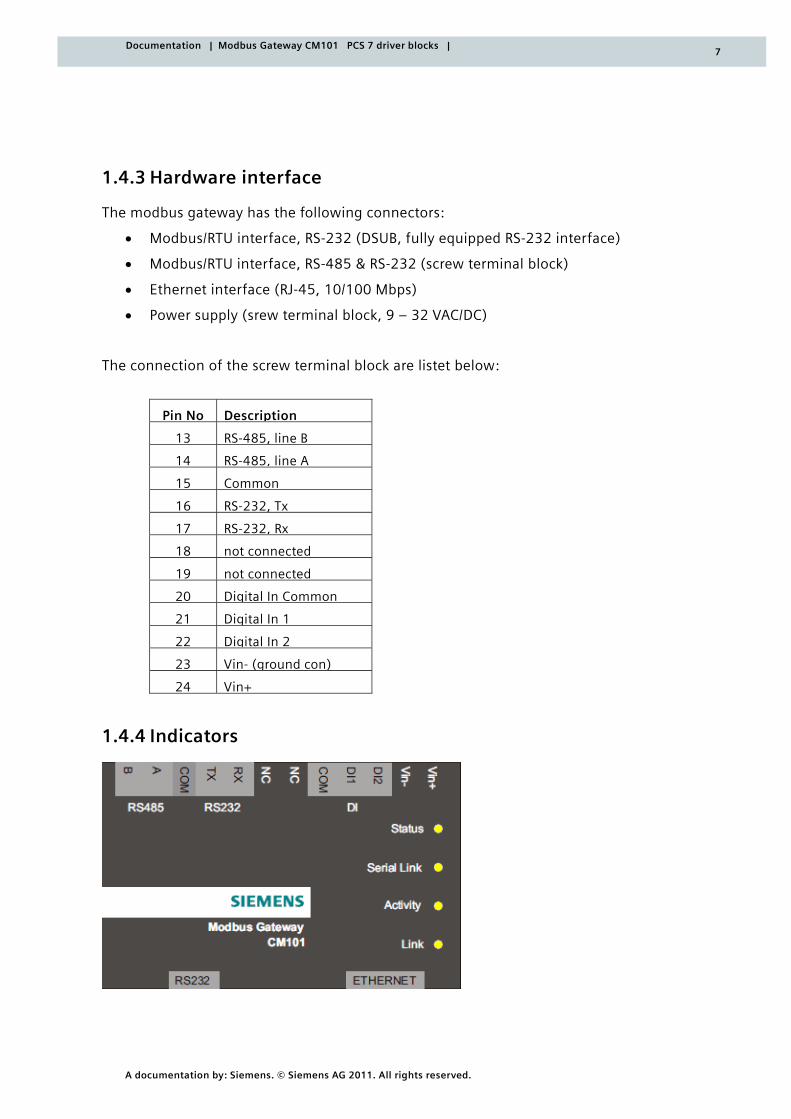
1.4.4 Indicators
8
A documentation by: Siemens. © Siemens AG 2011. All rights reserved.
Documentation | Modbus Gateway CM101 PCS 7 driver blocks |
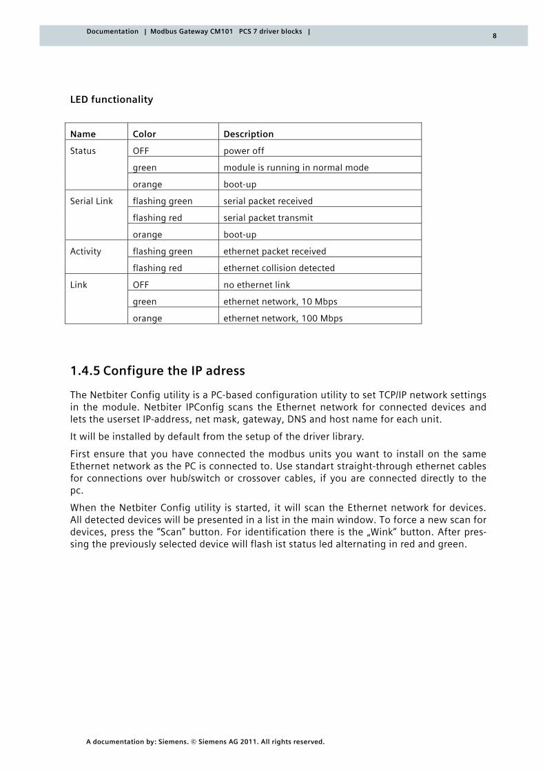
LED functionality
Name Color Description
Status OFF power off
green module is running in normal mode
orange boot-up
Serial Link flashing green serial packet received
flashing red serial packet transmit
orange boot-up
Activity flashing green ethernet packet received
flashing red ethernet collision detected
Link OFF no ethernet link
green ethernet network, 10 Mbps
orange ethernet network, 100 Mbps
1.4.5 Configure the IP adress
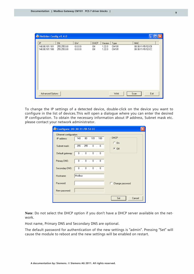
The Netbiter Config utility is a PC-based configuration utility to set TCP/IP network settings in the module. Netbiter IPConfig scans the Ethernet network for connected devices and lets the userset IP-address, net mask, gateway, DNS and host name for each unit.
It will be installed by default from the setup of the driver library.
First ensure that you have connected the modbus units you want to install on the same Ethernet network as the PC is connected to. Use standart straight-through ethernet cables for connections over hub/switch or crossover cables, if you are connected directly to the pc.
When the Netbiter Config utility is started, it will scan the Ethernet network for devices. All detected devices will be presented in a list in the main window. To force a new scan for devices, press the “Scan” button. For identification there is the „Wink“ button. After pres-sing the previously selected device will flash ist status led alternating in red and green.
9
A documentation by: Siemens. © Siemens AG 2011. All rights reserved.
Documentation | Modbus Gateway CM101 PCS 7 driver blocks |
To change the IP settings of a detected device, double-click on the device you want to configure in the list of devices.This will open a dialogue where you can enter the desired IP configuration. To obtain the necessary information about IP address, Subnet mask etc. please contact your network administrator.
Note: Do not select the DHCP option if you don’t have a DHCP server available on the net-work.
Host name, Primary DNS and Secondary DNS are optional.
The default password for authentication of the new settings is “admin”. Pressing “Set” will cause the module to reboot and the new settings will be enabled on restart.
10
A documentation by: Siemens. © Siemens AG 2011. All rights reserved.
Documentation | Modbus Gateway CM101 PCS 7 driver blocks |
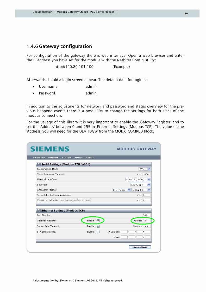
1.4.6 Gateway configuration
For configuration of the gateway there is web interface. Open a web browser and enter the IP address you have set for the module with the Netbiter Config utility:
http://140.80.101.100 (Example)
Afterwards should a login screen appear. The default data for login is:
• User name: admin
• Password: admin
In addition to the adjustments for network and password and status overview for the pre-vious happend events there is a possibility to change the settings for both sides of the modbus connection.
For the usuage of this library it is very important to enable the ‚Gateway Register’ and to set the ‘Address’ between 0 and 255 in ‚Ethernet Settings (Modbus TCP). The value of the ‘Address’ you will need for the DEV_IDGW from the MODX_COMRED block.
11
A documentation by: Siemens. © Siemens AG 2011. All rights reserved.
Documentation | Modbus Gateway CM101 PCS 7 driver blocks |
2.1 Step 7 block library
The driver blocks are installed with a setup as STEP 7 library.
The target directory
<installation directory>SIEMENS\STEP7\S7libs
is specified by default.
Following the installation, the driver blocks are available in the block library.
In the SIMATIC Manager, you can then open the library via
File Open Library
and thus access the function blocks.
2.2 Supported functionalities The current library supports the following functionalities:
• Integration of the driver blocks in a S7-400 or S7-400H CPU
• Modbus communication with the Modbus TCP/RTU Gateway via TCP/IP connection forwarding to the connected Modbus RTU Slaves
• The "Public Function Codes" 1 to 6 and 15 to 16 are supported
• The entire theoretic scope of external registers can be addressed, i.e. registers with the numbers 40001 to 105536 can be addressed if the Modbus slave device provides them
• No CPU restart is required after making changes to the parameters of the Modbus TCP/IP blocks
The following functions are not supported:
• Other codes besides the above-mentioned "Public Function Codes", "User-Defined Function Codes", and "Reserved Function Codes" are not supported
2.3 Communication principle The Modbus communication between the S7-400 system and the devices is based on the Request/Response communication principle between client and servers.
The S7-400 system acts as a TCP client and the used gateway device behaves like a TCP server. The S7-400 system (the Modbus master) sends the requests to the connected de-vices (the Modbus RTU slaves) and receives the responses to the requests and evaluates their content.
2 General information
12
A documentation by: Siemens. © Siemens AG 2011. All rights reserved.
Documentation | Modbus Gateway CM101 PCS 7 driver blocks |
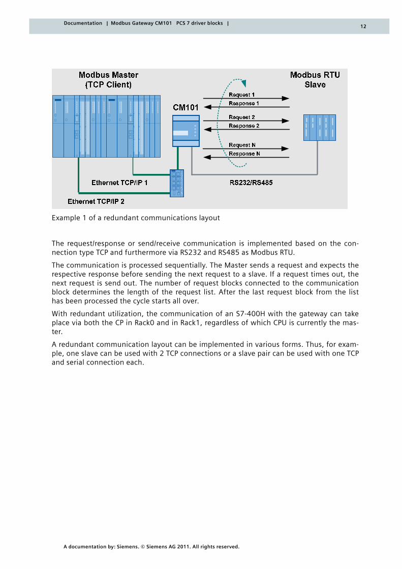
Example 1 of a redundant communications layout
The request/response or send/receive communication is implemented based on the con-nection type TCP and furthermore via RS232 and RS485 as Modbus RTU.
The communication is processed sequentially. The Master sends a request and expects the respective response before sending the next request to a slave. If a request times out, the next request is send out. The number of request blocks connected to the communication block determines the length of the request list. After the last request block from the list has been processed the cycle starts all over.
With redundant utilization, the communication of an S7-400H with the gateway can take place via both the CP in Rack0 and in Rack1, regardless of which CPU is currently the mas-ter.
A redundant communication layout can be implemented in various forms. Thus, for exam-ple, one slave can be used with 2 TCP connections or a slave pair can be used with one TCP and serial connection each.
13
A documentation by: Siemens. © Siemens AG 2011. All rights reserved.
Documentation | Modbus Gateway CM101 PCS 7 driver blocks |
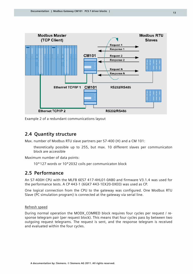
Example 2 of a redundant communications layout
2.4 Quantity structure Max. number of Modbus RTU slave partners per S7-400 (H) and a CM 101:
theoretically possible up to 255, but max. 10 different slaves per communicaton block are accessible
Maximum number of data points:
10*127 words or 10*2032 coils per communicaton block
2.5 Performance An S7-400H CPU with the MLFB 6ES7 417-4HL01-0AB0 and firmware V3.1.4 was used for the performance tests. A CP 443-1 (6GK7 443-1EX20-0XE0) was used as CP.
One logical connection from the CPU to the gateway was configured. One Modbus RTU Slave (PC simulation program) is connected at the gateway via serial line.
Refresh speed
During normal operation the MODX_COMRED block requires four cycles per request / re-sponse telegram pair (per request block). This means that four cycles pass by between two outgoing request telegrams. The request is sent, and the response telegram is received and evaluated within the four cycles.
14
A documentation by: Siemens. © Siemens AG 2011. All rights reserved.
Documentation | Modbus Gateway CM101 PCS 7 driver blocks |
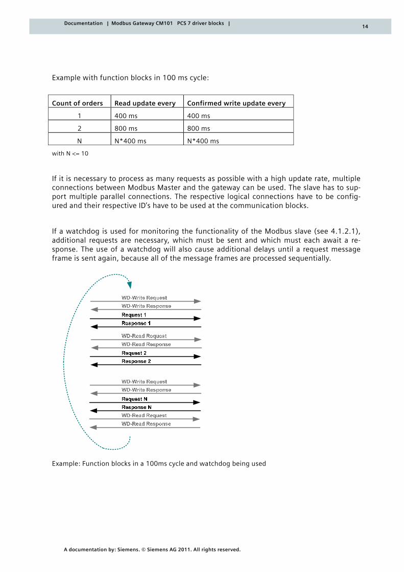
Example with function blocks in 100 ms cycle:
Count of orders Read update every Confirmed write update every
1 400 ms 400 ms
2 800 ms 800 ms
N N*400 ms N*400 ms
with N <= 10
If it is necessary to process as many requests as possible with a high update rate, multiple connections between Modbus Master and the gateway can be used. The slave has to sup-port multiple parallel connections. The respective logical connections have to be config-ured and their respective ID’s have to be used at the communication blocks.
If a watchdog is used for monitoring the functionality of the Modbus slave (see 4.1.2.1), additional requests are necessary, which must be sent and which must each await a re-sponse. The use of a watchdog will also cause additional delays until a request message frame is sent again, because all of the message frames are processed sequentially.
Example: Function blocks in a 100ms cycle and watchdog being used
15
A documentation by: Siemens. © Siemens AG 2011. All rights reserved.
Documentation | Modbus Gateway CM101 PCS 7 driver blocks |
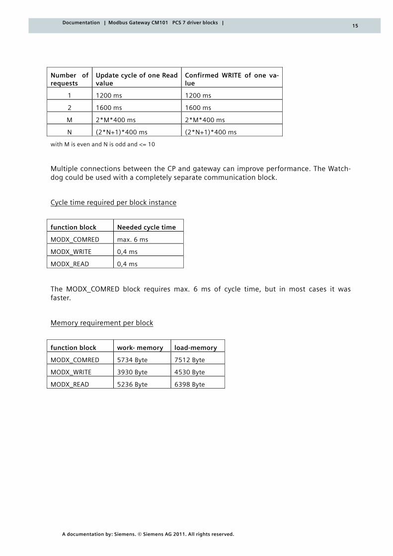
Number of requests
Update cycle of one Read value
Confirmed WRITE of one va-lue
1 1200 ms 1200 ms
2 1600 ms 1600 ms
M 2*M*400 ms 2*M*400 ms
N (2*N+1)*400 ms (2*N+1)*400 ms
with M is even and N is odd and <= 10
Multiple connections between the CP and gateway can improve performance. The Watch-dog could be used with a completely separate communication block.
Cycle time required per block instance
function block Needed cycle time
MODX_COMRED max. 6 ms
MODX_WRITE 0,4 ms
MODX_READ 0,4 ms
The MODX_COMRED block requires max. 6 ms of cycle time, but in most cases it was faster.
Memory requirement per block
function block work- memory load-memory
MODX_COMRED 5734 Byte 7512 Byte
MODX_WRITE 3930 Byte 4530 Byte
MODX_READ 5236 Byte 6398 Byte
16
A documentation by: Siemens. © Siemens AG 2011. All rights reserved.
Documentation | Modbus Gateway CM101 PCS 7 driver blocks |
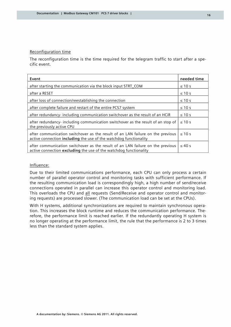
Reconfiguration time
The reconfiguration time is the time required for the telegram traffic to start after a spe-cific event.
Event needed time
after starting the communication via the block input STRT_COM ≤ 10 s
after a RESET ≤ 10 s
after loss of connection/reestablishing the connection ≤ 10 s
after complete failure and restart of the entire PCS7 system ≤ 10 s
after redundancy- including communication switchover as the result of an HCiR ≤ 10 s
after redundancy- including communication switchover as the result of an stop of the previously active CPU
≤ 10 s
after communication switchover as the result of an LAN failure on the previous active connection including the use of the watchdog functionality
≤ 10 s
after communication switchover as the result of an LAN failure on the previous active connection excluding the use of the watchdog functionality
≤ 40 s
Influence:
Due to their limited communications performance, each CPU can only process a certain number of parallel operator control and monitoring tasks with sufficient performance. If the resulting communication load is correspondingly high, a high number of send/receive connections operated in parallel can increase this operator control and monitoring load. This overloads the CPU and all requests (Send/Receive and operator control and monitor-ing requests) are processed slower. (The communication load can be set at the CPUs).
With H systems, additional synchronizations are required to maintain synchronous opera-tion. This increases the block runtime and reduces the communication performance. The-refore, the performance limit is reached earlier. If the redundantly operating H system is no longer operating at the performance limit, the rule that the performance is 2 to 3 times less than the standard system applies.
17
A documentation by: Siemens. © Siemens AG 2011. All rights reserved.
Documentation | Modbus Gateway CM101 PCS 7 driver blocks |
2.6 Communication blocks used
Data is sent from a CP via the LAN to a partner station or received from a partner station and then it must be transmitted from the CP to the CPU. If the user data length is 241 bytes or higher, the AG_LSEND and AG_LRECV FCs must be used to execute this task.
The following blocks of the SIMATIC_NET_CP library were therefore used for implementing the Modbus TCP/IP block library (S7-400H):
• AG_CNTRL (Version 1.0)
• AG_LSEND (Version 3.0 / Version 3.1 using PCS7 V7.1 SP2 or higher)
• AG_LRECV (Version 3.0 / Version 3.1 using PCS7 V7.1 SP2 or higher)
Information about which CP supports the AG_CNTRL with which firmware version can be found under Ethernet-CP and AG_CNTRL.
2.7 Required CP
Because the block AG_CNTRL is not supported from CP443-1 (EX11), it`s necessary to use the CP 443-1 (EX20). This CP can only be used since STEP7 V5.4 SP3 (PCS7 V7.0), because prior to that he is not available in HW catalogue. However the modbus gateway can be used with older versions of STEP7. You just have to design a CP443-1 (EX11) in HW Config and use the EX20 instead as hardware.
18
A documentation by: Siemens. © Siemens AG 2011. All rights reserved.
Documentation | Modbus Gateway CM101 PCS 7 driver blocks |
3.1 General configuration instructions
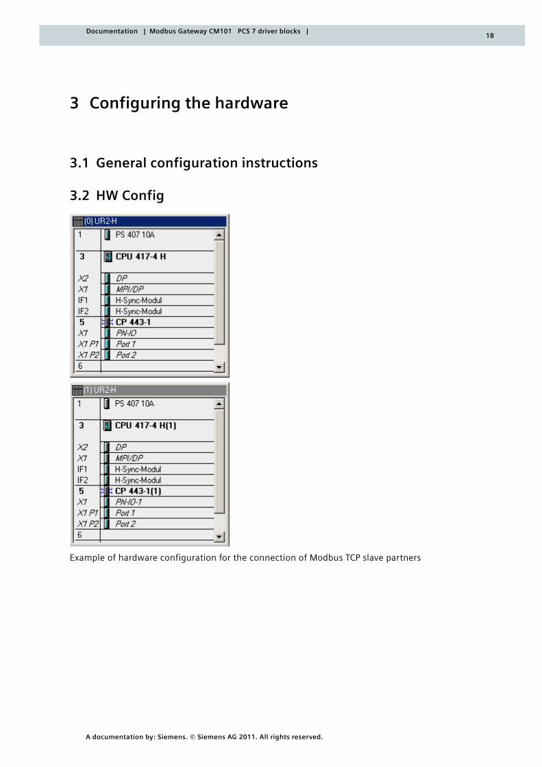
3.2 HW Config
Example of hardware configuration for the connection of Modbus TCP slave partners
3 Configuring the hardware
19
A documentation by: Siemens. © Siemens AG 2011. All rights reserved.
Documentation | Modbus Gateway CM101 PCS 7 driver blocks |
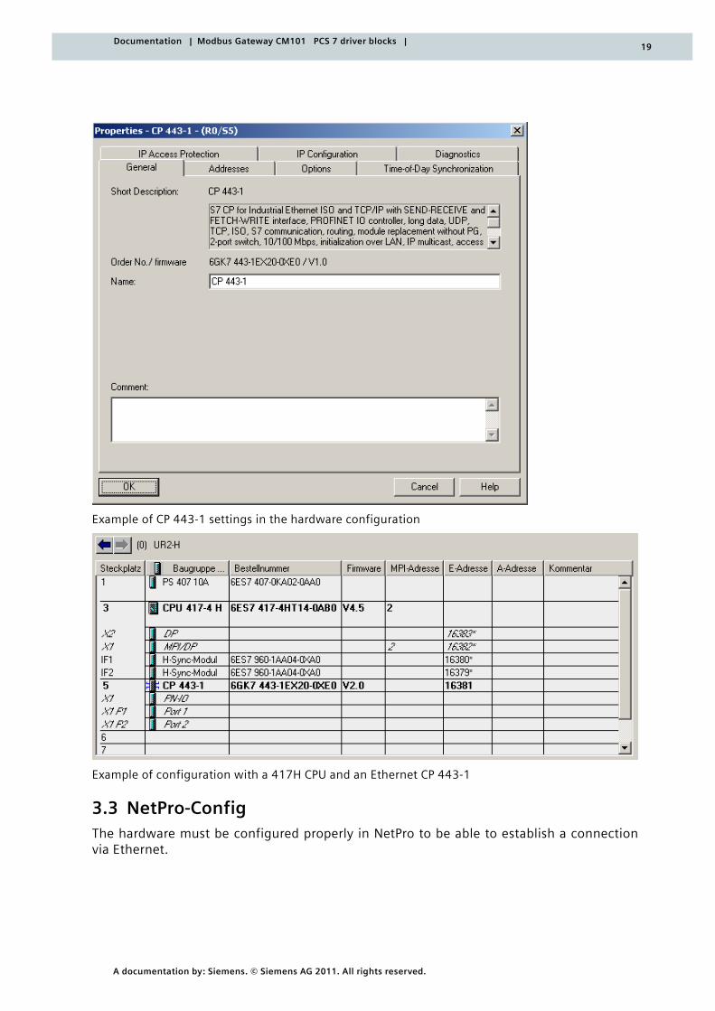
Example of CP 443-1 settings in the hardware configuration
Example of configuration with a 417H CPU and an Ethernet CP 443-1
3.3 NetPro-Config The hardware must be configured properly in NetPro to be able to establish a connection via Ethernet.
20
A documentation by: Siemens. © Siemens AG 2011. All rights reserved.
Documentation | Modbus Gateway CM101 PCS 7 driver blocks |
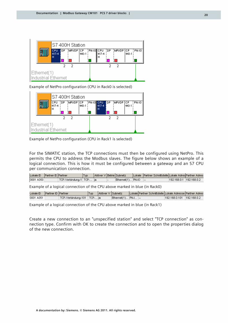
Example of NetPro configuration (CPU in Rack0 is selected)
Example of NetPro configuration (CPU in Rack1 is selected)
For the SIMATIC station, the TCP connections must then be configured using NetPro. This permits the CPU to address the Modbus slaves. The figure below shows an example of a logical connection. This is how it must be configured between a gateway and an S7 CPU per communication connection.
Example of a logical connection of the CPU above marked in blue (in Rack0)
Example of a logical connection of the CPU above marked in blue (in Rack1)
Create a new connection to an "unspecified station" and select "TCP connection" as con-nection type. Confirm with OK to create the connection and to open the properties dialog of the new connection.
21
A documentation by: Siemens. © Siemens AG 2011. All rights reserved.
Documentation | Modbus Gateway CM101 PCS 7 driver blocks |
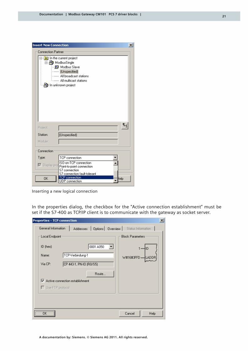
Inserting a new logical connection
In the properties dialog, the checkbox for the "Active connection establishment" must be set if the S7-400 as TCP/IP client is to communicate with the gateway as socket server.
22
A documentation by: Siemens. © Siemens AG 2011. All rights reserved.
Documentation | Modbus Gateway CM101 PCS 7 driver blocks |
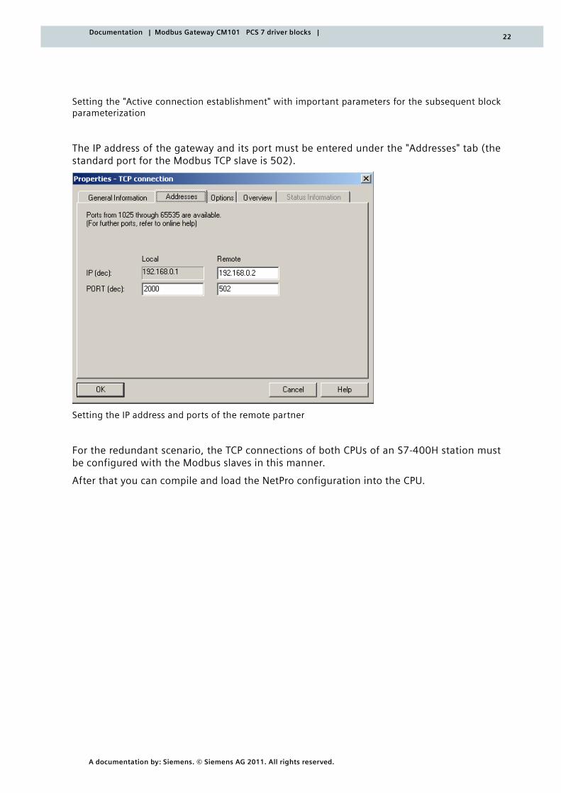
Setting the "Active connection establishment" with important parameters for the subsequent block parameterization
The IP address of the gateway and its port must be entered under the "Addresses" tab (the standard port for the Modbus TCP slave is 502).
Setting the IP address and ports of the remote partner
For the redundant scenario, the TCP connections of both CPUs of an S7-400H station must be configured with the Modbus slaves in this manner.
After that you can compile and load the NetPro configuration into the CPU.
23
A documentation by: Siemens. © Siemens AG 2011. All rights reserved.
Documentation | Modbus Gateway CM101 PCS 7 driver blocks |
4.1 MODX_COMRED – communication block
Type/number FB 536
4.1.1 Function and mode of operation
This block serves as central header block for controlling the communication via Modbus TCP/IP.
The function block handles the communication between an S7-400H and the Modbus TCP/RTU gateway as well as the connected Modbus RTU slaves (communication partner). The communication block must be interconnected with further blocks (the request tele-gram blocks). The communication block can only be used on a SIMATIC S7-41x or S7-41xH CPU with TCP/IP CPs (CP443-1 EX20). Furthermore, the CPU must be capable of signaling via ALARM_8P.
Max. 10 possible request blocks, which are sequentially processed, are connected to the MODX_COMRED block.
4.1.2 Parameterizing and interconnecting
In the CFC, the MODX_COMRED block is interconnected via its CONNECT output with the CONNECT inputs of the MODX_WRITE and/or MODX_READ request blocks to be processed. A defined processing sequence of the individual requests might be required in certain ap-plications. The processing sequence can be configured through the run sequence of the request blocks in the CFC.
If more than 10 request blocks are connected, any connected blocks from the eleventh position on are not considered. These unconsidered request blocks can be recognized by their set error output QLNKF. Incorrectly parameterized request blocks are also not consid-ered for communication.
The number of valid connected request blocks is indicated at the QBLOCKS output.
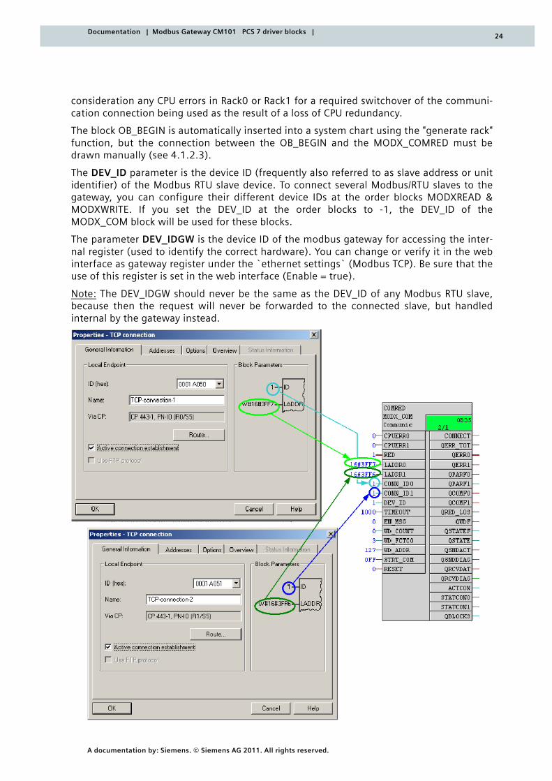
The important parameters for communication must be entered at the inputs LADDR0, LADDR1, CONN_ID0, CONN_ID1. The logical address of the CPs (LADDRx) and the value of the CONN_IDx parameters can be obtained from the block parameters in the properties dialog of the NetPro connection. In case multiple communication blocks are used, each block should have its own logical connection between the Modbus Master and the gate-way.
The communication can be started and stopped via the STRT_COM switch. A reinitializa-tion of the program run or restart of the communication can be enforced with the input RESET.
The inputs CPUERR0 and CPUERR1 must be connected with the outputs CPUERR_0 and CPUERR_1 of the OB_BEGIN from the PCS7 Basis Library in order to detect and take into
4 Description of the function blocks
24
A documentation by: Siemens. © Siemens AG 2011. All rights reserved.
Documentation | Modbus Gateway CM101 PCS 7 driver blocks |
consideration any CPU errors in Rack0 or Rack1 for a required switchover of the communi-cation connection being used as the result of a loss of CPU redundancy.
The block OB_BEGIN is automatically inserted into a system chart using the "generate rack" function, but the connection between the OB_BEGIN and the MODX_COMRED must be drawn manually (see 4.1.2.3).
The DEV_ID parameter is the device ID (frequently also referred to as slave address or unit identifier) of the Modbus RTU slave device. To connect several Modbus/RTU slaves to the gateway, you can configure their different device IDs at the order blocks MODXREAD & MODXWRITE. If you set the DEV_ID at the order blocks to -1, the DEV_ID of the MODX_COM block will be used for these blocks.
The parameter DEV_IDGW is the device ID of the modbus gateway for accessing the inter-nal register (used to identify the correct hardware). You can change or verify it in the web interface as gateway register under the `ethernet settings` (Modbus TCP). Be sure that the use of this register is set in the web interface (Enable = true).
Note: The DEV_IDGW should never be the same as the DEV_ID of any Modbus RTU slave, because then the request will never be forwarded to the connected slave, but handled internal by the gateway instead.
25
A documentation by: Siemens. © Siemens AG 2011. All rights reserved.
Documentation | Modbus Gateway CM101 PCS 7 driver blocks |
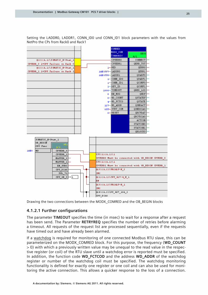
Setting the LADDR0, LADDR1, CONN_ID0 und CONN_ID1 block parameters with the values from NetPro the CPs from Rack0 and Rack1
Drawing the two connections between the MODX_COMRED and the OB_BEGIN blocks
4.1.2.1 Further configurations
The parameter TIMEOUT specifies the time (in msec) to wait for a response after a request has been send. The Parameter RETRYREQ specifies the number of retries before alarming a timeout. All requests of the request list are processed sequentially, even if the requests have timed out and have already been alarmed.
If a watchdog is required for monitoring of one connected Modbus RTU slave, this can be parameterized on the MODX_COMRED block. For this purpose, the frequency (WD_COUNT > 0) with which a previously written value may be unequal to the read value in the respec-tive register (or coil) of the RTU slave until a watchdog error is reported must be specified. In addition, the function code WD_FCTCOD and the address WD_ADDR of the watchdog register or number of the watchdog coil must be specified. The watchdog monitoring functionality is defined for exactly one register or one coil and can also be used for moni-toring the active connection. This allows a quicker response to the loss of a connection.
26
A documentation by: Siemens. © Siemens AG 2011. All rights reserved.
Documentation | Modbus Gateway CM101 PCS 7 driver blocks |
The detection of a lost connection by the CP alone with AG_CNTRL (i.e. without the use of a watchdog) takes approximately 30 seconds. When a watchdog error occurs, the commu-nication is switched over <= 10s from the currently active connection to the standby con-nection, assuming that the standby connection has not already been reported as faulted at this time.
The parameter ACTCONIN forces the active connection (0 for CP0 and 1 for CP1) for com-munication. Automatic switch over of connections is only activated when ACTCON = -1.
The MODX_COMRED block can also be used for a non-redundant system. To this end, the redundancy can be disconnected via the input RED. When doing this, ensure that the block parameters with a 0 at the end of their names are the relevant parameters for this application, and the parameters with a 1 at the end of their names are not taken into con-sideration. Only CP0 is used for communication.
4.1.2.2 Additional information
If there is no response to the request telegrams for all connected request blocks within the specified timeout and the specified number of retries, or if responses cannot be inter-preted because there are unexpected data in the receive buffer of the CP, the connection to the gateway will be restarted. This automatic reset is only carried out, however, if this condition continues for double the timeout value during the program run.
The following outputs are used for analyzing
o the internal program sequence QSTATEF and QSTATE
o for alerting QMSG_ERR, QMSG_DONE, QMSG_SUP, QMSG_STAT and QMSG_ACK
o for indicating the slots QRACK_NO0, QRACK_NO1, QSLOT_NO0 and QSLOT_NO1
o for analyzing the communication. QSNDACT, QSNDDIAG, QRCVDAT and QRCVDIAG
o and for analyzing the connection status. ACTCON, STATCON0 and STATCON1
QSNDACT =1 means that 'data are being sent' and QRCVDAT = 1 means that 'data are being received'. ACTCON indicates an active connection. With 0, communication with the Mod-bus slave takes place via the connection from the CP in Rack0; with 1, via the CP in Rack1.
In QSNDDIAG, the STATUS of AG_LSEND is displayed and in QRCVDIAG, the STATUS of AG_LRECV is displayed. In STATCON0, the connection status of the CP in Rack0 with the communication partner is indicated with the aid of the AG_CNTRL and in STATCON1, a cor-responding indication is given for the connection from the CP in Rack1. The information is returned in RESULT1 for CMD=1 by calling up AG_CNTRL.
Information regarding the STATUS and RESULT values are available in the respective online help of AG_ LSEND, AG_LRECV and AG_CNTRL or in the SIMTIC NET Manual.
To accept changed LADDR and CONN_ID parameter values, a restart of the communication or RESET is required.
Blocks called from the interface are:
o FB531 (MODX_BuildReq)
o FB532 (MODX_ParseReq)
27
A documentation by: Siemens. © Siemens AG 2011. All rights reserved.
Documentation | Modbus Gateway CM101 PCS 7 driver blocks |
o FB533 (MODX_ProgLogic)
o FB534 (MODX_Link)
o FB521 (MODTCP_ConnStat)
o FB522 (MODTCP_ConnRes)
o SFB35 (ALARM_8P)
Blocks called from the code are:
o FC10 (AG_CNTRL)*
o FC50 (AG_LSEND)
o FC60 (AG_LRECV)
o SFC6 (RD_SINFO)
o SFC20 (BLKMOV)*
o SFC49 (LGC_GADR)
*MODX_COMRED uses AG_CNTRL indirectly via FB521 and FB522.
*MODX_COMRED uses BLKMOV indirectly via FB531 and FB532.
4.1.2.3 Creating module drivers
When compiling a CFC, the function "Generate module drivers" must be used for signal processing in PCS 7. This function generates new system charts (with names assigned by the system "@..."), in which only driver blocks are inserted by the driver generator.
After the hardware is configured using HW Config and the technological functions are configured in the CFC, this function automatically generates, interconnects and param-eterizes the necessary module drivers. These module drivers are responsible for the diag-nosing and reporting of errors during signal processing.
With the setup for the MODX_COMRED block, an object list and an action list are installed in the form of two XML files. This allows the driver generator to also automatically insert the necessary OB_BEGIN block (into a system chart).
The two installed metafiles (here for PCS7 V7.1) are:
<ProgramFiles>\SIEMENS\STEP7\S7DATA\driver\action\07010000\al_chn_MODX_COMRED.xml
<ProgramFiles>\SIEMENS\STEP7\S7DATA\driver\object\07010000\chn_MODX_COMRED.xml
The connections between the OB_BEGIN and the MODX_COMRED block must, however, still be drawn manually, because the assignment of the "channel" block to its associated diagnostic block cannot be made known to the driver generator.
Generating the module driver the warning ‘Cannot find driver block for the signal process-ing block %blockname%’ will be shown for each MODX_COMRED block. This warning can be ignored.
After a change to the HW configuration, the driver generator must be restarted.
4.1.3 Calling OBs
The calling OB is the cyclic interrupt OB3x, into which you integrate the block (e.g. OB 35) and the following OBs, into which the block is also integrated (automatically in the CFC):
28
A documentation by: Siemens. © Siemens AG 2011. All rights reserved.
Documentation | Modbus Gateway CM101 PCS 7 driver blocks |
o OB100 Restart (warm restart)
o OB102 Restart (cold restart)
4.1.4 Error handling
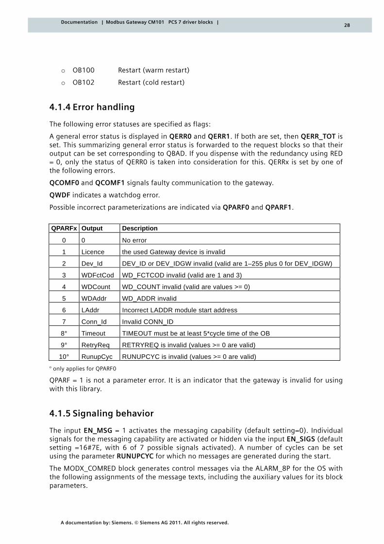
The following error statuses are specified as flags:
A general error status is displayed in QERR0 and QERR1. If both are set, then QERR_TOT is set. This summarizing general error status is forwarded to the request blocks so that their output can be set corresponding to QBAD. If you dispense with the redundancy using RED = 0, only the status of QERR0 is taken into consideration for this. QERRx is set by one of the following errors.
QCOMF0 and QCOMF1 signals faulty communication to the gateway.
QWDF indicates a watchdog error.
Possible incorrect parameterizations are indicated via QPARF0 and QPARF1.
QPARFx Output Description
0 0 No error
1 Licence the used Gateway device is invalid
2 Dev_Id DEV_ID or DEV_IDGW invalid (valid are 1–255 plus 0 for DEV_IDGW)
3 WDFctCod WD_FCTCOD invalid (valid are 1 and 3)
4 WDCount WD_COUNT invalid (valid are values >= 0)
5 WDAddr WD_ADDR invalid
6 LAddr Incorrect LADDR module start address
7 Conn_Id Invalid CONN_ID
8° Timeout TIMEOUT must be at least 5*cycle time of the OB
9° RetryReq RETRYREQ is invalid (values >= 0 are valid)
10° RunupCyc RUNUPCYC is invalid (values >= 0 are valid)
° only applies for QPARF0
QPARF = 1 is not a parameter error. It is an indicator that the gateway is invalid for using with this library.
4.1.5 Signaling behavior
The input EN_MSG = 1 activates the messaging capability (default setting=0). Individual signals for the messaging capability are activated or hidden via the input EN_SIGS (default setting =16#7E, with 6 of 7 possible signals activated). A number of cycles can be set using the parameter RUNUPCYC for which no messages are generated during the start.
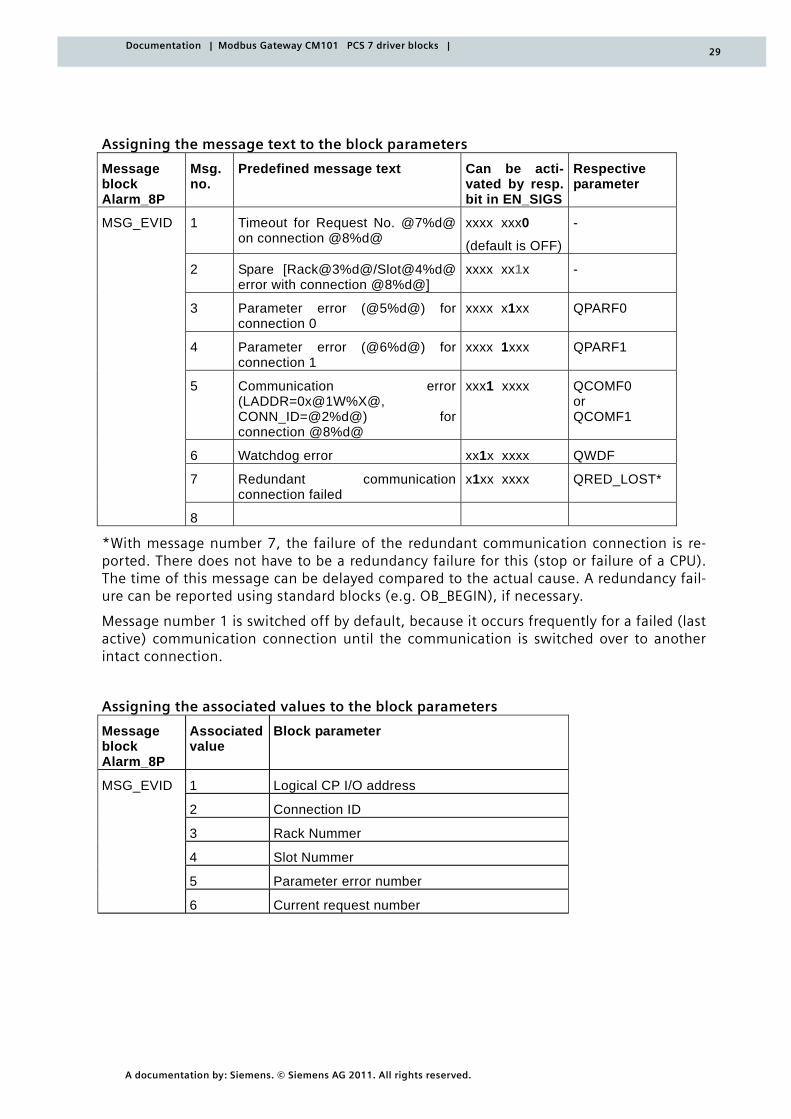
The MODX_COMRED block generates control messages via the ALARM_8P for the OS with the following assignments of the message texts, including the auxiliary values for its block parameters.
29
A documentation by: Siemens. © Siemens AG 2011. All rights reserved.
Documentation | Modbus Gateway CM101 PCS 7 driver blocks |
Assigning the message text to the block parameters
Message block Alarm_8P
Msg. no.
Predefined message text Can be acti-vated by resp. bit in EN_SIGS
Respective parameter
1 Timeout for Request No. @7%d@ on connection @8%d@
xxxx xxx0 (default is OFF)
-
2 Spare [Rack@3%d@/Slot@4%d@ error with connection @8%d@]
xxxx xx1x -
3 Parameter error (@5%d@) for connection 0
xxxx x1xx QPARF0
4 Parameter error (@6%d@) for connection 1
xxxx 1xxx QPARF1
5 Communication error (LADDR=0x@1W%X@, CONN_ID=@2%d@) forconnection @8%d@
xxx1 xxxx QCOMF0 or QCOMF1
6 Watchdog error xx1x xxxx QWDF
7 Redundant communicationconnection failed
x1xx xxxx QRED_LOST*
MSG_EVID
8
*With message number 7, the failure of the redundant communication connection is re-ported. There does not have to be a redundancy failure for this (stop or failure of a CPU). The time of this message can be delayed compared to the actual cause. A redundancy fail-ure can be reported using standard blocks (e.g. OB_BEGIN), if necessary.
Message number 1 is switched off by default, because it occurs frequently for a failed (last active) communication connection until the communication is switched over to another intact connection.
Assigning the associated values to the block parameters
Message block Alarm_8P
Associated value
Block parameter
1 Logical CP I/O address
2 Connection ID
3 Rack Nummer
4 Slot Nummer
5 Parameter error number
MSG_EVID
6 Current request number
30
A documentation by: Siemens. © Siemens AG 2011. All rights reserved.
Documentation | Modbus Gateway CM101 PCS 7 driver blocks |
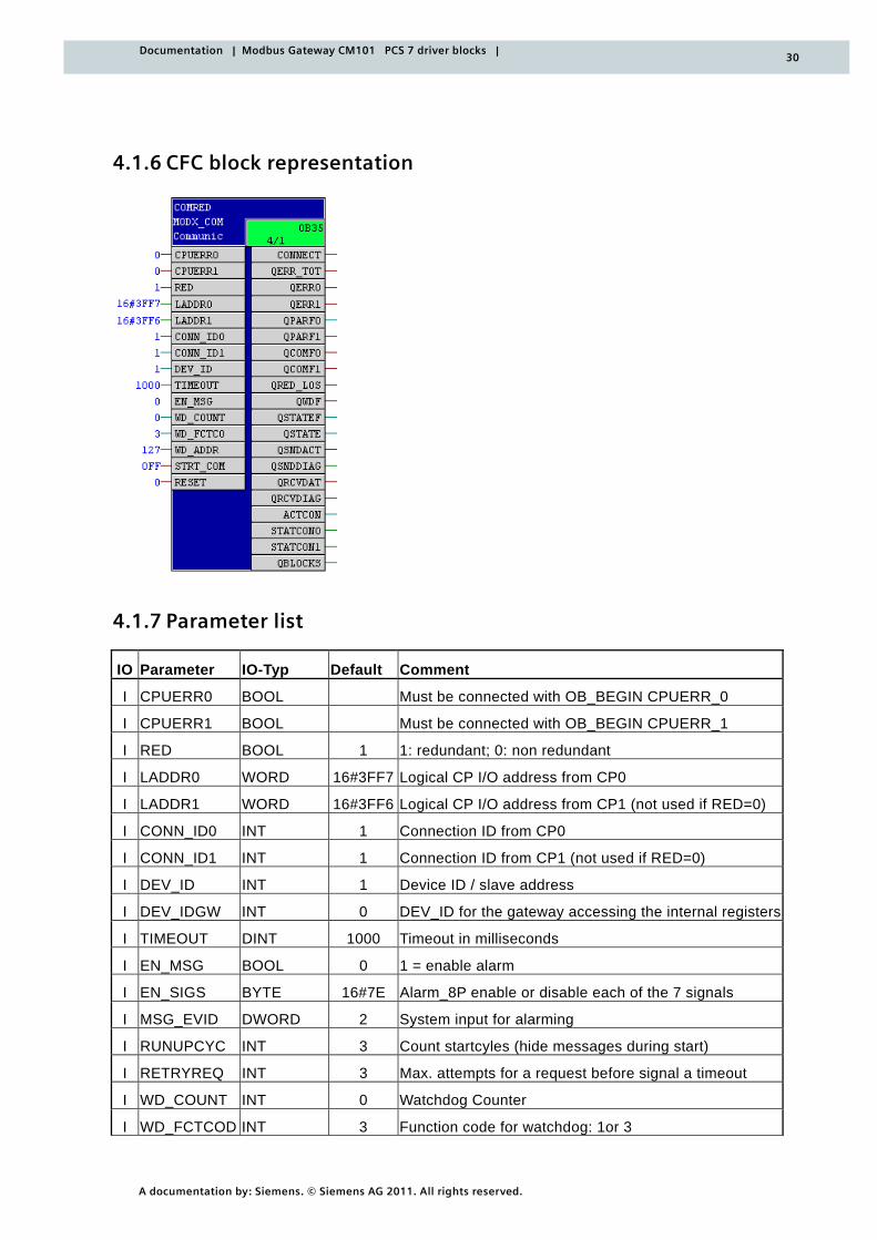
4.1.6 CFC block representation
4.1.7 Parameter list
IO Parameter IO-Typ Default Comment
I CPUERR0 BOOL Must be connected with OB_BEGIN CPUERR_0
I CPUERR1 BOOL Must be connected with OB_BEGIN CPUERR_1
I RED BOOL 1 1: redundant; 0: non redundant
I LADDR0 WORD 16#3FF7 Logical CP I/O address from CP0
I LADDR1 WORD 16#3FF6 Logical CP I/O address from CP1 (not used if RED=0)
I CONN_ID0 INT 1 Connection ID from CP0
I CONN_ID1 INT 1 Connection ID from CP1 (not used if RED=0)
I DEV_ID INT 1 Device ID / slave address
I DEV_IDGW INT 0 DEV_ID for the gateway accessing the internal registers
I TIMEOUT DINT 1000 Timeout in milliseconds
I EN_MSG BOOL 0 1 = enable alarm
I EN_SIGS BYTE 16#7E Alarm_8P enable or disable each of the 7 signals
I MSG_EVID DWORD 2 System input for alarming
I RUNUPCYC INT 3 Count startcyles (hide messages during start)
I RETRYREQ INT 3 Max. attempts for a request before signal a timeout
I WD_COUNT INT 0 Watchdog Counter
I WD_FCTCOD INT 3 Function code for watchdog: 1or 3
31
A documentation by: Siemens. © Siemens AG 2011. All rights reserved.
Documentation | Modbus Gateway CM101 PCS 7 driver blocks |
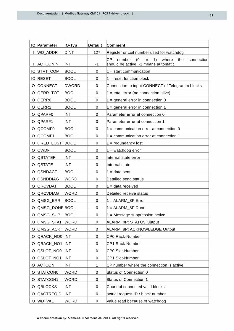
IO Parameter IO-Typ Default Comment
I WD_ADDR DINT 127 Register or coil number used for watchdog
I ACTCONIN INT -1 CP number (0 or 1) where the connectionshould be active, -1 means automatic
IO STRT_COM BOOL 0 1 = start communication
IO RESET BOOL 0 1 = reset function block
O CONNECT DWORD 0 Connection to input CONNECT of Telegramm blocks
O QERR_TOT BOOL 0 1 = total error (no connection alive)
O QERR0 BOOL 0 1 = general error in connection 0
O QERR1 BOOL 0 1 = general error in connection 1
O QPARF0 INT 0 Parameter error at connection 0
O QPARF1 INT 0 Parameter error at connection 1
O QCOMF0 BOOL 0 1 = communication error at connection 0
O QCOMF1 BOOL 0 1 = communication error at connection 1
O QRED_LOST BOOL 0 1 = redundancy lost
O QWDF BOOL 0 1 = watchdog error
O QSTATEF INT 0 Internal state error
O QSTATE INT 0 Internal state
O QSNDACT BOOL 0 1 = data sent
O QSNDDIAG WORD 0 Detailed send status
O QRCVDAT BOOL 0 1 = data received
O QRCVDIAG WORD 0 Detailed receive status
O QMSG_ERR BOOL 0 1 = ALARM_8P Error
O QMSG_DONE BOOL 0 1 = ALARM_8P Done
O QMSG_SUP BOOL 0 1 = Message suppression active
O QMSG_STAT WORD 0 ALARM_8P: STATUS Output
O QMSG_ACK WORD 0 ALARM_8P: ACKNOWLEDGE Output
O QRACK_NO0 INT 0 CP0 Rack-Number
O QRACK_NO1 INT 0 CP1 Rack-Number
O QSLOT_NO0 INT 0 CP0 Slot-Number
O QSLOT_NO1 INT 0 CP1 Slot-Number
O ACTCON INT 1 CP number where the connection is active
O STATCON0 WORD 0 Status of Connection 0
O STATCON1 WORD 0 Status of Connection 1
O QBLOCKS INT 0 Count of connected valid blocks
O QACTREQID INT 0 actual request ID / block number
O WD_VAL WORD 0 Value read because of watchdog
32
A documentation by: Siemens. © Siemens AG 2011. All rights reserved.
Documentation | Modbus Gateway CM101 PCS 7 driver blocks |
4.2 MODX_WRITE - request block
Type/number FB 538
4.2.1 Function and mode of operation
The MODX_WRITE block is used to compile Modbus write requests and its attached data are sent to the Modbus RTU slave.
The MODX_WRITE block is used together with the MODX_COMRED block for writing data into so-called coils (bits) or registers (words) of the Modbus RTU slave device using the Modbus protocol.
It writes the pending data at the inputs and any data in a parameterized data block into the corresponding register(s) or coil(s).
4.2.2 Parameterizing and interconnecting
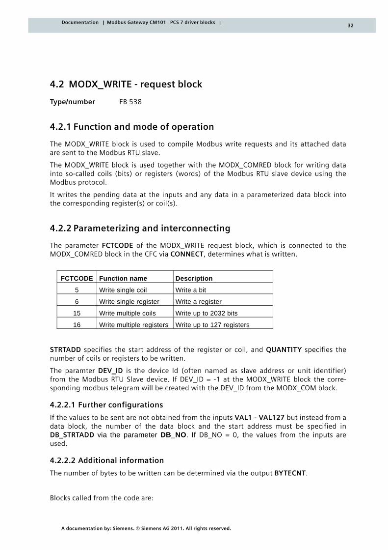
The parameter FCTCODE of the MODX_WRITE request block, which is connected to the MODX_COMRED block in the CFC via CONNECT, determines what is written.
FCTCODE Function name Description
5 Write single coil Write a bit
6 Write single register Write a register
15 Write multiple coils Write up to 2032 bits
16 Write multiple registers Write up to 127 registers
STRTADD specifies the start address of the register or coil, and QUANTITY specifies the number of coils or registers to be written.
The paramter DEV_ID is the device Id (often named as slave address or unit identifier) from the Modbus RTU Slave device. If DEV_ID = -1 at the MODX_WRITE block the corre-sponding modbus telegram will be created with the DEV_ID from the MODX_COM block.
4.2.2.1 Further configurations
If the values to be sent are not obtained from the inputs VAL1 - VAL127 but instead from a data block, the number of the data block and the start address must be specified in DB_STRTADD via the parameter DB_NO. If DB_NO = 0, the values from the inputs are used.
4.2.2.2 Additional information
The number of bytes to be written can be determined via the output BYTECNT.
Blocks called from the code are:
33
A documentation by: Siemens. © Siemens AG 2011. All rights reserved.
Documentation | Modbus Gateway CM101 PCS 7 driver blocks |
o FC29 (NE_STRING)
o SFC20 (BLKMOV)
4.2.3 Calling OBs
The calling OB is the cyclic interrupt OB3x in which you integrate the block (e.g. OB 35).
4.2.4 Error handling
QLNKF indicates an error when the connection to the MODX_COMRED block is faulty or when the MODX_WRITE block itself could not be registered internally, e.g. because more than 10 request blocks are already connected.
QBAD indicates that the write request was invalid. It is TRUE when QLNKF is TRUE or QERR at the MODX_COMRED block is TRUE. Furthermore it is TRUE when the write request came back with a response code <> 0 and <>15 (refer QRESPCOD).
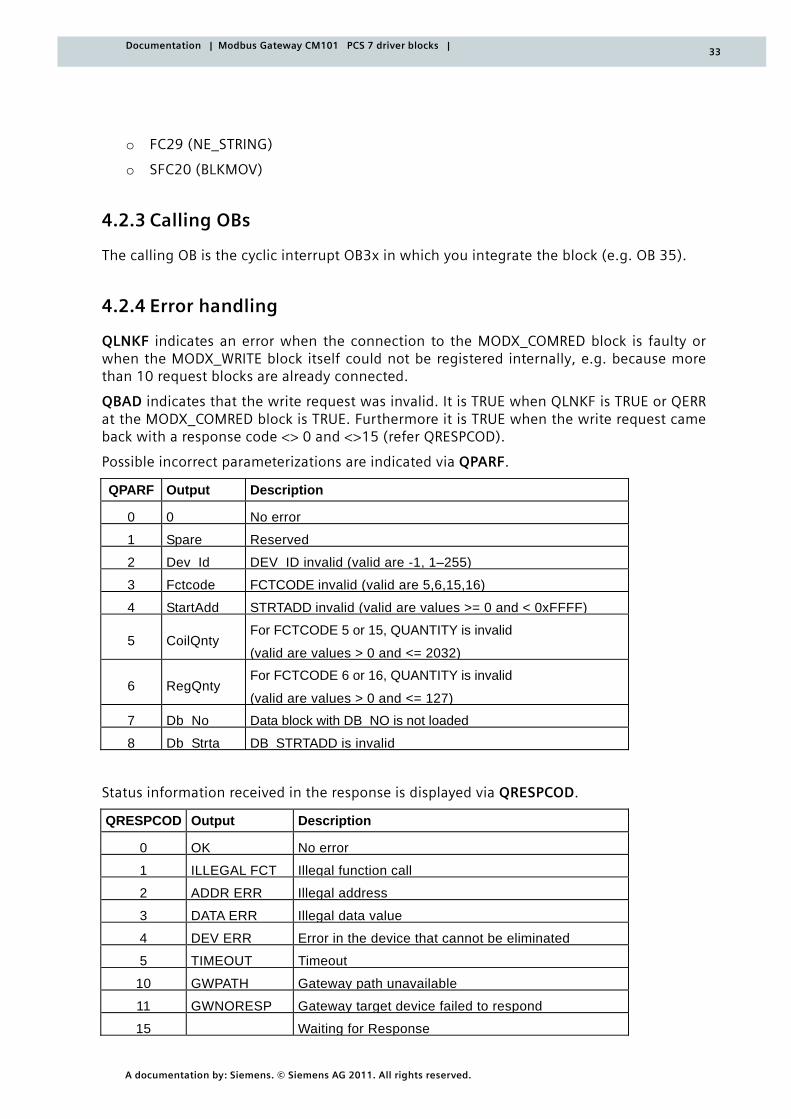
Possible incorrect parameterizations are indicated via QPARF.
QPARF Output Description
0 0 No error
1 Spare Reserved
2 Dev Id DEV ID invalid (valid are -1, 1–255)
3 Fctcode FCTCODE invalid (valid are 5,6,15,16)
4 StartAdd STRTADD invalid (valid are values >= 0 and < 0xFFFF)
5 CoilQnty For FCTCODE 5 or 15, QUANTITY is invalid
(valid are values > 0 and <= 2032)
6 RegQnty For FCTCODE 6 or 16, QUANTITY is invalid
(valid are values > 0 and <= 127)
7 Db No Data block with DB NO is not loaded
8 Db Strta DB STRTADD is invalid
Status information received in the response is displayed via QRESPCOD.
QRESPCOD Output Description
0 OK No error
1 ILLEGAL FCT Illegal function call
2 ADDR ERR Illegal address
3 DATA ERR Illegal data value
4 DEV ERR Error in the device that cannot be eliminated
5 TIMEOUT Timeout
10 GWPATH Gateway path unavailable
11 GWNORESP Gateway target device failed to respond
15 Waiting for Response
34
A documentation by: Siemens. © Siemens AG 2011. All rights reserved.
Documentation | Modbus Gateway CM101 PCS 7 driver blocks |
4.2.5 Signaling behavior
The block has no signaling behavior.
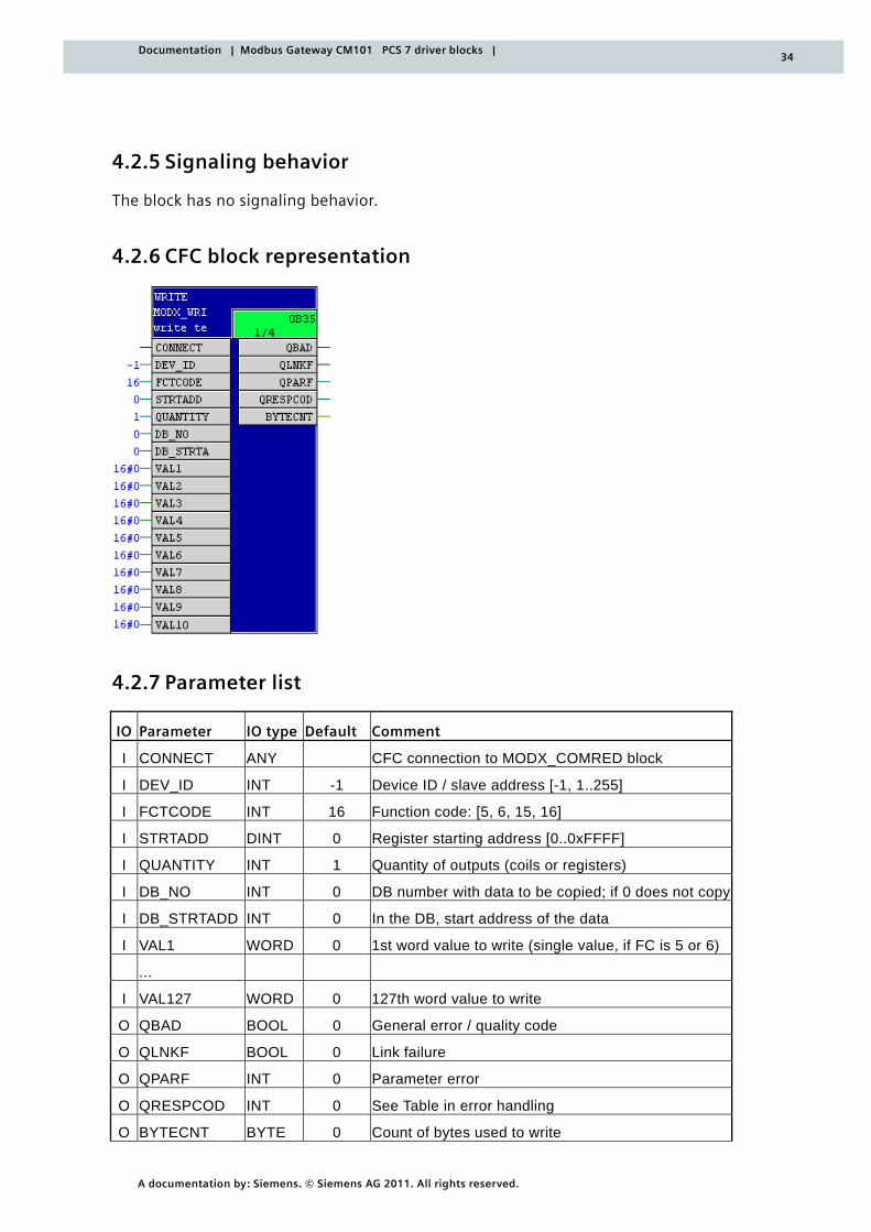
4.2.6 CFC block representation
4.2.7 Parameter list
IO Parameter IO type Default Comment
I CONNECT ANY CFC connection to MODX_COMRED block
I DEV_ID INT -1 Device ID / slave address [-1, 1..255]
I FCTCODE INT 16 Function code: [5, 6, 15, 16]
I STRTADD DINT 0 Register starting address [0..0xFFFF]
I QUANTITY INT 1 Quantity of outputs (coils or registers)
I DB_NO INT 0 DB number with data to be copied; if 0 does not copy
I DB_STRTADD INT 0 In the DB, start address of the data
I VAL1 WORD 0 1st word value to write (single value, if FC is 5 or 6)
...
I VAL127 WORD 0 127th word value to write
O QBAD BOOL 0 General error / quality code
O QLNKF BOOL 0 Link failure
O QPARF INT 0 Parameter error
O QRESPCOD INT 0 See Table in error handling
O BYTECNT BYTE 0 Count of bytes used to write
35
A documentation by: Siemens. © Siemens AG 2011. All rights reserved.
Documentation | Modbus Gateway CM101 PCS 7 driver blocks |
4.3 MODX_READ - request block
Type/number FB 537
4.3.1 Function and mode of operation
The MODX_READ block is used to compile Modbus read requests and to process the data received in the associated response.
The MODX_READ block is used together with the MODX_COMRED block for reading data from so-called coils (bits) or registers (words) of the Modbus RTU slave device using the Modbus protocol.
The received data are displayed at the block outputs or can be transferred to an optionally specified data block.
4.3.2 Parameterizing and interconnecting
On the CFC level, the CONNECT input of the request block MODX_READ must be con-nected to the CONNECT output of the MODX_COMRED.
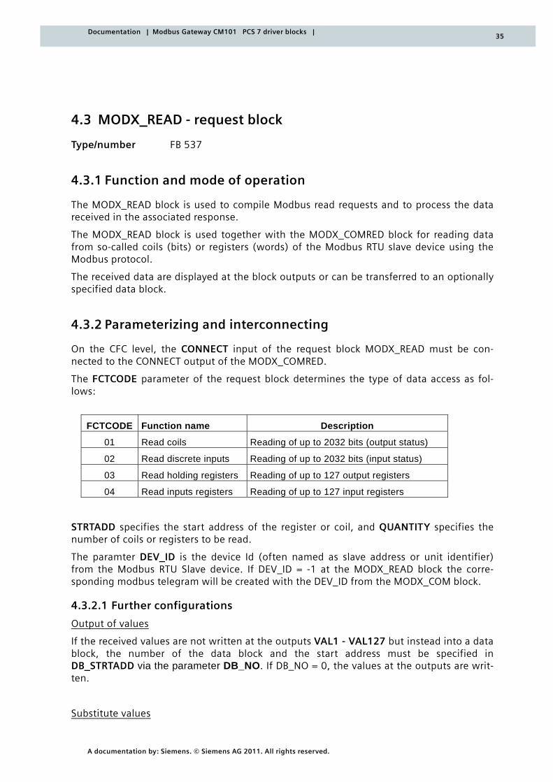
The FCTCODE parameter of the request block determines the type of data access as fol-lows:
FCTCODE Function name Description
01 Read coils Reading of up to 2032 bits (output status)
02 Read discrete inputs Reading of up to 2032 bits (input status)
03 Read holding registers Reading of up to 127 output registers
04 Read inputs registers Reading of up to 127 input registers
STRTADD specifies the start address of the register or coil, and QUANTITY specifies the number of coils or registers to be read.
The paramter DEV_ID is the device Id (often named as slave address or unit identifier) from the Modbus RTU Slave device. If DEV_ID = -1 at the MODX_READ block the corre-sponding modbus telegram will be created with the DEV_ID from the MODX_COM block.
4.3.2.1 Further configurations
Output of values
If the received values are not written at the outputs VAL1 - VAL127 but instead into a data block, the number of the data block and the start address must be specified in DB_STRTADD via the parameter DB_NO. If DB_NO = 0, the values at the outputs are writ-ten.
Substitute values
36
A documentation by: Siemens. © Siemens AG 2011. All rights reserved.
Documentation | Modbus Gateway CM101 PCS 7 driver blocks |
Substitute values can be specified for the MODX_READ block via the inputs SUB_VAL1 – SUB_VAL127. If SUB_ACT = TRUE in the event of communication problems QBAD = TRUE, these values can be copied to the outputs. Only as many values as specified via QUANTITY (considering the FCTCODE) are copied.
Simulation values
Simulation values can be specified for the MODX_READ block via the inputs SIM_VAL1 – SIM_VAL127. If SIM_ACT = TRUE, these values are copied to the outputs. Only as many values as specified via QUANTITY (considering the FCTCODE) are copied. Values that may have been read from the Modbus slave or replacement values are overwritten by the simu-lation values.
Byte and word sequence
Since it is not exactly specified in the Modbus specification how data is to be stored in the registers, some manufacturers implement their Modbus devices such that first the High byte and then the Low byte is stored and transferred. Other devices, on the other hand, save and transfer the Low byte first.
The same applies to words if registers were combined in 32-bit data types. Some devices save the High word in the first register and the Low word in the second register. In other devices, on the other hand, this is implemented in the reverse order.
An example is the 32-bit unsigned integer 2923517522, which can be arranged in four different ways:
AE41 5652 : high byte first, high word first
5652 AE41 : high byte first, low word first
41AE 5256 : low byte first, high word first
5256 41AE : low byte first, low word first
It does not matter in which order the bytes or words are sent as long as this can be con-sidered at the receiver end.
Therefore, the values can be adapted at the outputs with the MODX_READ block with the CHG_BYTE and CHG_WORD switches. The switches are only considered if FCTCODE = 3 or 4. Substitute values and simulation values are not modified. With CHG_BYTE = TRUE, the High byte and Low byte of an output value (also in any specified DB) are interchanged. With CHG_WORD = TRUE, the High word and Low word of a double word are interchanged. The double word is then put together through two consecutive outputs. The same applies to values in any specified DB. When using CHG_WORD, make sure that an even number of registers to be read is available.
4.3.2.2 Additional information
Blocks called from the code:
o FC29 (NE_STRING)
o SFC20 (BLKMOV)
37
A documentation by: Siemens. © Siemens AG 2011. All rights reserved.
Documentation | Modbus Gateway CM101 PCS 7 driver blocks |
4.3.3 Calling OBs
The calling OB is the cyclic interrupt OB3x in which you integrate the block (e.g. OB 35).
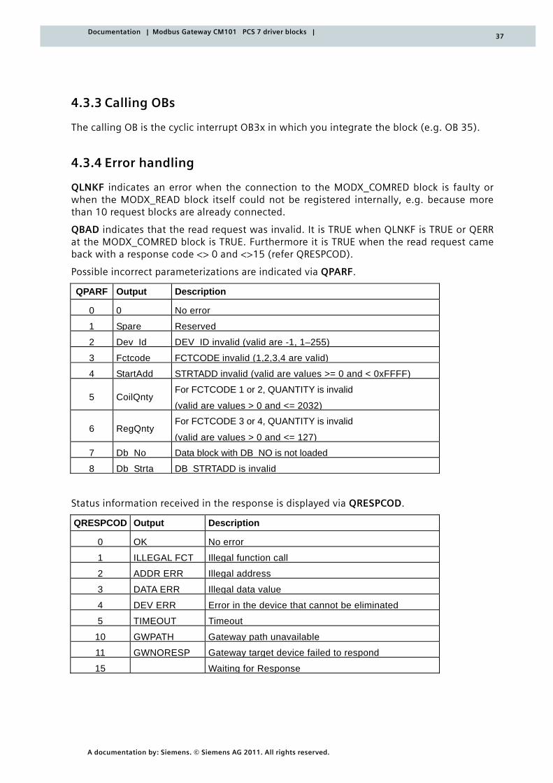
4.3.4 Error handling
QLNKF indicates an error when the connection to the MODX_COMRED block is faulty or when the MODX_READ block itself could not be registered internally, e.g. because more than 10 request blocks are already connected.
QBAD indicates that the read request was invalid. It is TRUE when QLNKF is TRUE or QERR at the MODX_COMRED block is TRUE. Furthermore it is TRUE when the read request came back with a response code <> 0 and <>15 (refer QRESPCOD).
Possible incorrect parameterizations are indicated via QPARF.
QPARF Output Description
0 0 No error
1 Spare Reserved
2 Dev Id DEV ID invalid (valid are -1, 1–255)
3 Fctcode FCTCODE invalid (1,2,3,4 are valid)
4 StartAdd STRTADD invalid (valid are values >= 0 and < 0xFFFF)
5 CoilQnty For FCTCODE 1 or 2, QUANTITY is invalid
(valid are values > 0 and <= 2032)
6 RegQnty For FCTCODE 3 or 4, QUANTITY is invalid
(valid are values > 0 and <= 127)
7 Db No Data block with DB NO is not loaded
8 Db Strta DB STRTADD is invalid
Status information received in the response is displayed via QRESPCOD.
QRESPCOD Output Description
0 OK No error
1 ILLEGAL FCT Illegal function call
2 ADDR ERR Illegal address
3 DATA ERR Illegal data value
4 DEV ERR Error in the device that cannot be eliminated
5 TIMEOUT Timeout
10 GWPATH Gateway path unavailable
11 GWNORESP Gateway target device failed to respond
15 Waiting for Response
38
A documentation by: Siemens. © Siemens AG 2011. All rights reserved.
Documentation | Modbus Gateway CM101 PCS 7 driver blocks |
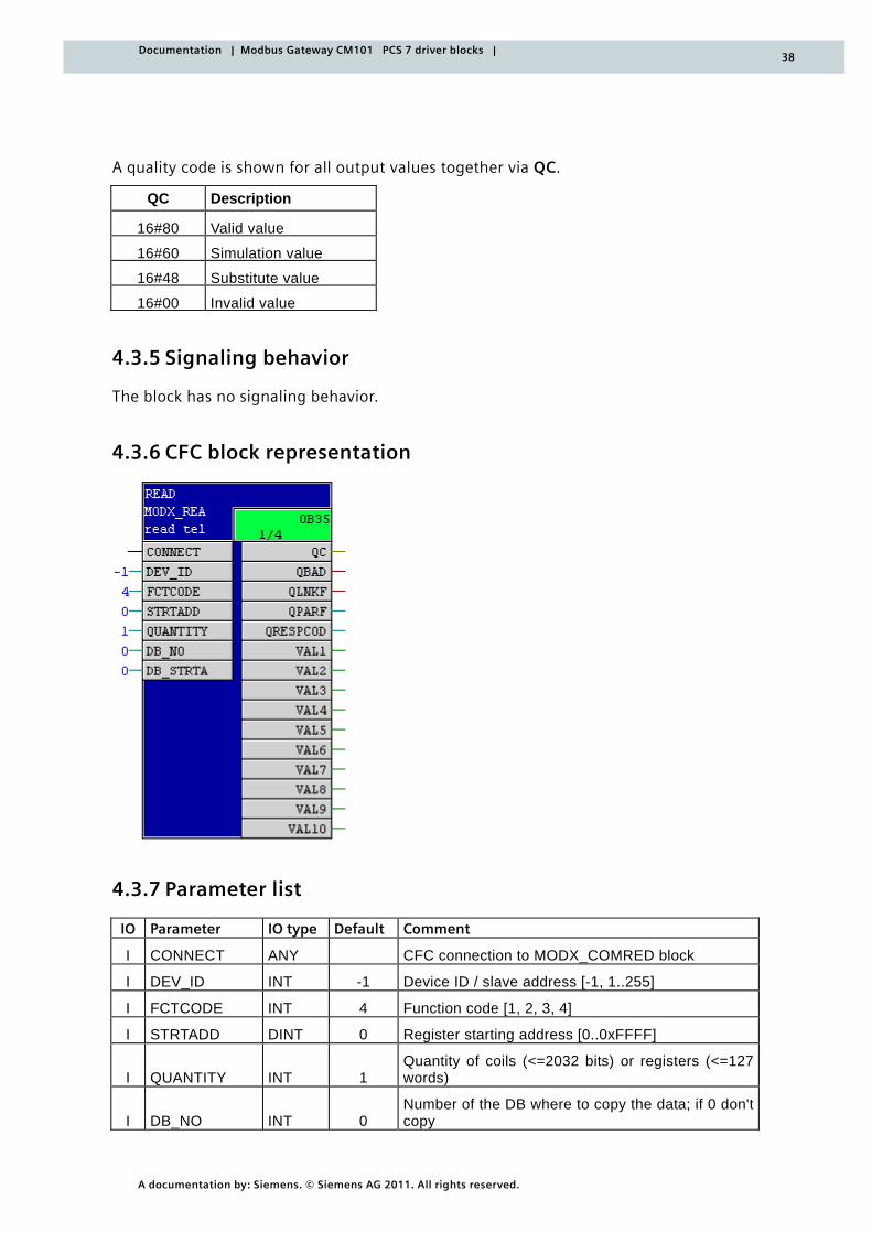
A quality code is shown for all output values together via QC.
QC Description
16#80 Valid value
16#60 Simulation value
16#48 Substitute value
16#00 Invalid value
4.3.5 Signaling behavior
The block has no signaling behavior.
4.3.6 CFC block representation
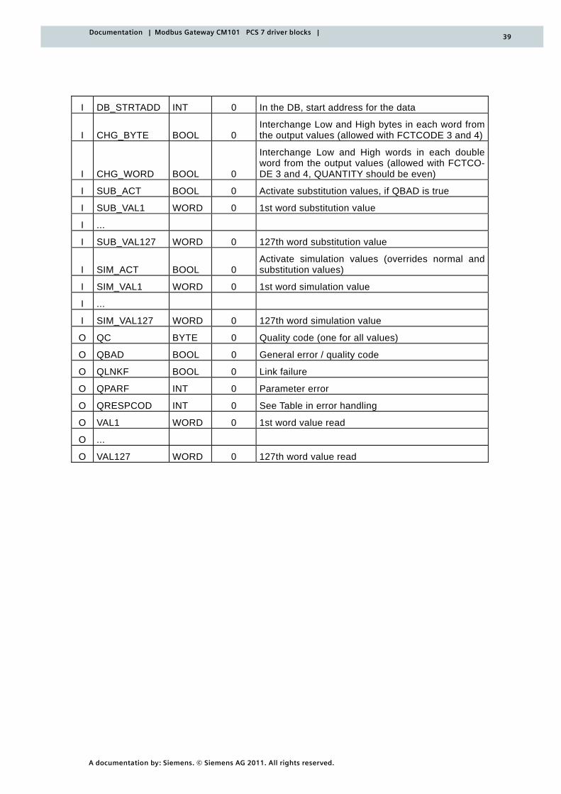
4.3.7 Parameter list
IO Parameter IO type Default Comment
I CONNECT ANY CFC connection to MODX_COMRED block
I DEV_ID INT -1 Device ID / slave address [-1, 1..255]
I FCTCODE INT 4 Function code [1, 2, 3, 4]
I STRTADD DINT 0 Register starting address [0..0xFFFF]
I QUANTITY INT 1 Quantity of coils (<=2032 bits) or registers (<=127 words)
I DB_NO INT 0 Number of the DB where to copy the data; if 0 don't copy
39
A documentation by: Siemens. © Siemens AG 2011. All rights reserved.
Documentation | Modbus Gateway CM101 PCS 7 driver blocks |
I DB_STRTADD INT 0 In the DB, start address for the data
I CHG_BYTE BOOL 0 Interchange Low and High bytes in each word from the output values (allowed with FCTCODE 3 and 4)
I CHG_WORD BOOL 0
Interchange Low and High words in each double word from the output values (allowed with FCTCO-DE 3 and 4, QUANTITY should be even)
I SUB_ACT BOOL 0 Activate substitution values, if QBAD is true
I SUB_VAL1 WORD 0 1st word substitution value
I ...
I SUB_VAL127 WORD 0 127th word substitution value
I SIM_ACT BOOL 0 Activate simulation values (overrides normal and substitution values)
I SIM_VAL1 WORD 0 1st word simulation value
I ...
I SIM_VAL127 WORD 0 127th word simulation value
O QC BYTE 0 Quality code (one for all values)
O QBAD BOOL 0 General error / quality code
O QLNKF BOOL 0 Link failure
O QPARF INT 0 Parameter error
O QRESPCOD INT 0 See Table in error handling
O VAL1 WORD 0 1st word value read
O ...
O VAL127 WORD 0 127th word value read
40
A documentation by: Siemens. © Siemens AG 2011. All rights reserved.
Documentation | Modbus Gateway CM101 PCS 7 driver blocks |
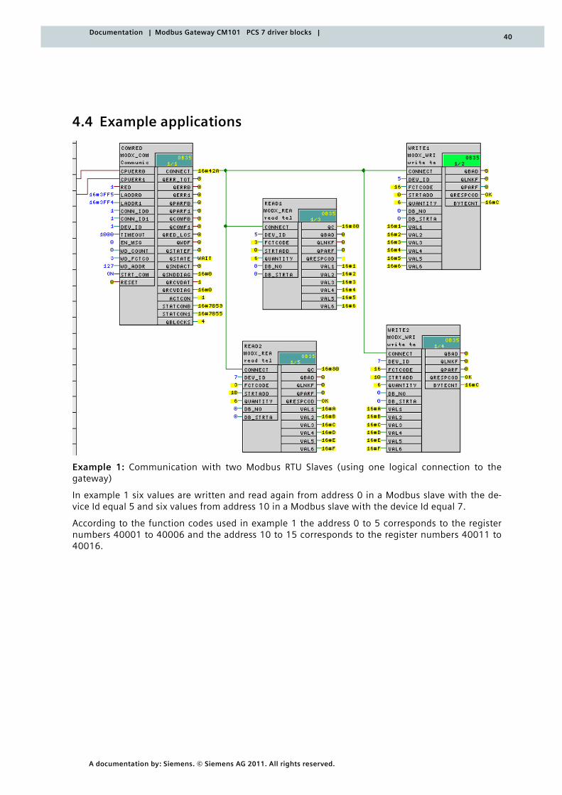
4.4 Example applications
Example 1: Communication with two Modbus RTU Slaves (using one logical connection to the gateway)
In example 1 six values are written and read again from address 0 in a Modbus slave with the de-vice Id equal 5 and six values from address 10 in a Modbus slave with the device Id equal 7.
According to the function codes used in example 1 the address 0 to 5 corresponds to the register numbers 40001 to 40006 and the address 10 to 15 corresponds to the register numbers 40011 to 40016.
41
A documentation by: Siemens. © Siemens AG 2011. All rights reserved.
Documentation | Modbus Gateway CM101 PCS 7 driver blocks |
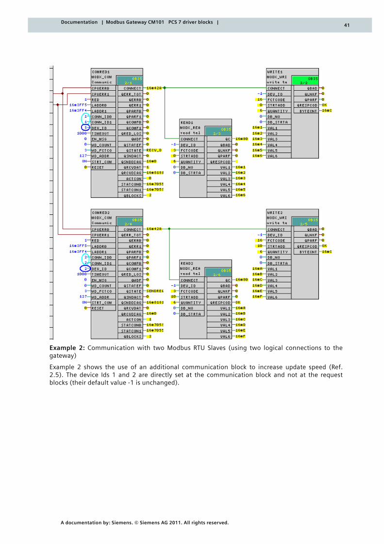
Example 2: Communication with two Modbus RTU Slaves (using two logical connections to the gateway)
Example 2 shows the use of an additional communication block to increase update speed (Ref. 2.5). The device Ids 1 and 2 are directly set at the communication block and not at the request blocks (their default value -1 is unchanged).
42
A documentation by: Siemens. © Siemens AG 2011. All rights reserved.
Documentation | Modbus Gateway CM101 PCS 7 driver blocks |
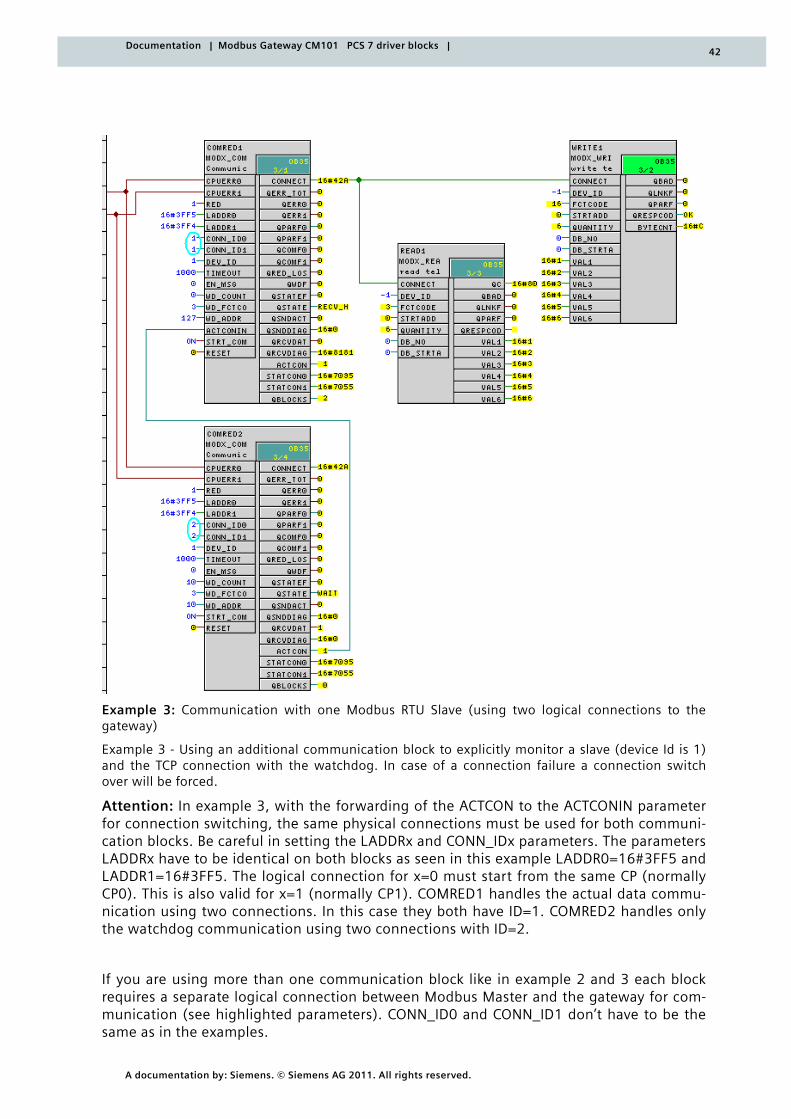
Example 3: Communication with one Modbus RTU Slave (using two logical connections to the gateway)
Example 3 - Using an additional communication block to explicitly monitor a slave (device Id is 1) and the TCP connection with the watchdog. In case of a connection failure a connection switch over will be forced.
Attention: In example 3, with the forwarding of the ACTCON to the ACTCONIN parameter for connection switching, the same physical connections must be used for both communi-cation blocks. Be careful in setting the LADDRx and CONN_IDx parameters. The parameters LADDRx have to be identical on both blocks as seen in this example LADDR0=16#3FF5 and LADDR1=16#3FF5. The logical connection for x=0 must start from the same CP (normally CP0). This is also valid for x=1 (normally CP1). COMRED1 handles the actual data commu-nication using two connections. In this case they both have ID=1. COMRED2 handles only the watchdog communication using two connections with ID=2.
If you are using more than one communication block like in example 2 and 3 each block requires a separate logical connection between Modbus Master and the gateway for com-munication (see highlighted parameters). CONN_ID0 and CONN_ID1 don’t have to be the same as in the examples.

43
A documentation by: Siemens. © Siemens AG 2011. All rights reserved.
Documentation | Modbus Gateway CM101 PCS 7 driver blocks |
The connections for CPUERR0 and CPUERR1 are interconnected with the outputs CPUERR_0 and CPUERR_1 of the CPU Function Blocks 'OB_BEGIN', which have been automatically in-serted in a system chart via the "Generate module driver" function.
44
A documentation by: Siemens. © Siemens AG 2011. All rights reserved.
Documentation | Modbus Gateway CM101 PCS 7 driver blocks |
4.5 W1R_SCALE - Conversion block
Type/number FB 519
4.5.1 Function and mode of operation
This block is used for converting a 16-bit value (provided by a word) into a REAL value, taking into account a specified linear scaling. The values processed by this block are usu-ally analog values.
The algorithm is as follows:
PV_OUT := ((HI_RANGE - LO_RANGE)*((X - MIN_RAW)* 1/(MAX_RAW-MIN_RAW)) + LO_RANGE)* FACTOR;
X stands for the input value (PV_IN) that was converted into the REAL data type.
4.5.2 Parameterizing and interconnecting
The 16-bit input value (the measured variable) is specified in PV_IN. The range of the in-put value corresponds to the range of values of a 16-bit integer (-32768 [8000] to +32767 [7FFF]).
The limit value for the upper range of the measuring signal is specified in HI_RANGE.
The limit value for the lower range of the measuring signal is specified in LO_RANGE.
The upper limit of the measuring range is specified in MAX_RAW.
The lower limit of the measuring range is specified in MIN_RAW.
An amplification factor can be specified in FACTOR.
The calculated output variable (measuring signal) is output to PV_OUT.
The values at the input can be adapted by means of the CHG_BYTE switch. With CHG_BYTE = TRUE, the High byte and Low byte of the input word are interchanged.
4.5.3 Calling OBs
The calling OB is the cyclic interrupt OB3x into which you integrate the block (e.g. OB 35) and the following OB into which the block is also integrated (automatically in the CFC):
o OB100 Restart (warm restart)
4.5.4 Error handling
Possible incorrect parameterizations are indicated via QPARF.
QPARF Output Description
0 0 No error
1 InvRange Invalid range indicated
(HI_RANGE must be greater than LO_RANGE)
45
A documentation by: Siemens. © Siemens AG 2011. All rights reserved.
Documentation | Modbus Gateway CM101 PCS 7 driver blocks |
QPARF Output Description
2 InvRawLi
Invalid limits for the raw values
(MAX_RAW must be greater than MIN_RAW and
MAX_RAW <= 32767.0 and
MIN_RAW >= -32768.0 apply)
4.5.5 Signaling behavior
The block has no signaling behavior.
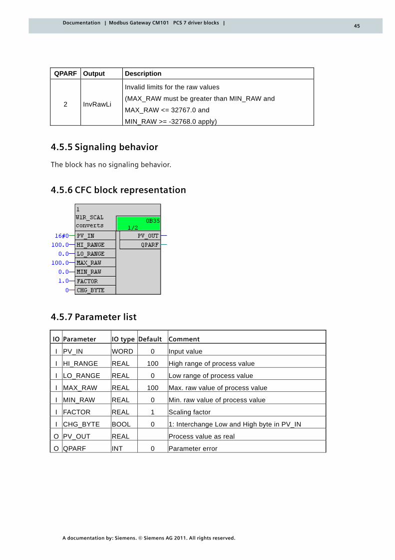
4.5.6 CFC block representation
4.5.7 Parameter list
IO Parameter IO type Default Comment
I PV_IN WORD 0 Input value
I HI_RANGE REAL 100 High range of process value
I LO_RANGE REAL 0 Low range of process value
I MAX_RAW REAL 100 Max. raw value of process value
I MIN_RAW REAL 0 Min. raw value of process value
I FACTOR REAL 1 Scaling factor
I CHG_BYTE BOOL 0 1: Interchange Low and High byte in PV_IN
O PV_OUT REAL Process value as real
O QPARF INT 0 Parameter error
46
A documentation by: Siemens. © Siemens AG 2011. All rights reserved.
Documentation | Modbus Gateway CM101 PCS 7 driver blocks |
4.6 W2R_SCALE - conversion block
Type/number FB 520
4.6.1 Function and mode of operation
This block is used for converting a 32-bit value (comprising two words) into a REAL value, taking into account a specified linear scaling. The values processed by this block are usu-ally analog values.
The algorithm is as follows:
PV_OUT := ((HI_RANGE - LO_RANGE)*((X - MIN_RAW)* 1/(MAX_RAW-MIN_RAW)) + LO_RANGE)* FACTOR;
X stands for the input value (comprising PV_IN1 as high word and PV_IN2 as low word) that was converted into the REAL data type.
4.6.2 Parameterizing and interconnecting
The 32-bit input value (the measured variable) is specified in PV_IN (as high word) and PV_IN2 (as low word). The range of the input value (given by the 2 words in PV_IN1 and PV_IN2) corresponds to the range of values of a 32-bit integer (-2 147 483 648 [8000 FFFF] to +2 147 483 647 [7FFF FFFF]).
The limit value for the upper range of the measuring signal is specified in HI_RANGE.
The limit value for the lower range of the measuring signal is specified in LO_RANGE.
The upper limit of the measuring range is specified in MAX_RAW.
The lower limit of the measuring range is specified in MIN_RAW.
An amplification factor can be specified in FACTOR.
The calculated output variable (measuring signal) is output to PV_OUT.
The values at the inputs can be adapted with the switches CHG_BYTE and CHG_WORD. With CHG_BYTE = TRUE, the High byte and Low byte of both input words are interchanged. With CHG_WORD = TRUE, the High word and Low word in the double word are inter-changed. The double word is put together using the two words at the input. Usually the word at the PV_IN1 input is the high word and the word at the PV_IN2 input is the low word.
4.6.3 Calling OBs
The calling OB is the cyclic interrupt OB3x into which you integrate the block (e.g. OB 35) and the following OB into which the block is also integrated (automatically in the CFC):
o OB100 Restart (warm restart)
4.6.4 Error handling
Possible incorrect parameterizations are indicated via QPARF.
47
A documentation by: Siemens. © Siemens AG 2011. All rights reserved.
Documentation | Modbus Gateway CM101 PCS 7 driver blocks |
QPARF Output Description
0 0 No error
1 InvRange Invalid range indicated
(HI_RANGE must be greater than LO_RANGE!)
2 InvRawLi
Invalid limits for the raw values
(MAX_RAW must be greater than MIN_RAW and
MAX_RAW <= 2 147 483 647.0 and
MIN_RAW >= -2 147 483 648.0 apply
4.6.5 Signaling behavior
The block has no signaling behavior.
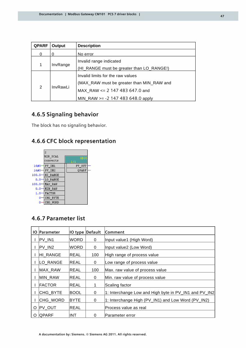
4.6.6 CFC block representation
4.6.7 Parameter list
IO Parameter IO type Default Comment
I PV_IN1 WORD 0 Input value1 (High Word)
I PV_IN2 WORD 0 Input value2 (Low Word)
I HI_RANGE REAL 100 High range of process value
I LO_RANGE REAL 0 Low range of process value
I MAX_RAW REAL 100 Max. raw value of process value
I MIN_RAW REAL 0 Min. raw value of process value
I FACTOR REAL 1 Scaling factor
I CHG_BYTE BOOL 0 1: Interchange Low and High byte in PV_IN1 and PV_IN2
I CHG_WORD BYTE 0 1: Interchange High (PV_IN1) and Low Word (PV_IN2)
O PV_OUT REAL Process value as real
O QPARF INT 0 Parameter error

48
A documentation by: Siemens. © Siemens AG 2011. All rights reserved.
Documentation | Modbus Gateway CM101 PCS 7 driver blocks |
www.siemens.com [email protected] Tel: +49 (0) 721/595 - 7522 All rights reserved. All trademarks used are owned by Siemens or their respective owners. © Siemens AG 2011
Siemens AG I IS IN OC OL A Siemensallee 84 76187 Karlsruhe GERMANY