Embed Size (px)
Citation preview

Mode- and wavelength-division multiplexed transmission using all-fiber mode multiplexer
based on mode selective couplers Sun Hyok Chang,1,* Hwan Seok Chung,1 Roland Ryf,2 Nicolas K. Fontaine,2
Changyo Han,1 Kyung Jun Park,3 Kwangjoon Kim,1 Jyung Chan Lee,1 Jong Hyun Lee,1 Byoung Yoon Kim,3 and Young Kie Kim4
1Optical Internet Research Department, Electronics and Telecommunications Research Institute, 138 Gajeongno, Yuseong, Daejeon, 305-700, South Korea
2Bell Laboratories, Alcatel-Lucent, 791 Holmdel Rd, Holmdel, NJ 07733, USA 3Department of Physics, KAIST, Daejeon, 305-701, South Korea
4KS Photonics, Daejeon, 305-710, South Korea *[email protected]
Abstract: We propose all-fiber mode multiplexer composed of two consecutive LP11 mode selective couplers that allows for the multiplexing of LP01 mode and two-fold degenerate LP11 modes. We demonstrate WDM transmission of 32 wavelength channels with 100 GHz spacing, each carrying 3 modes of 120 Gb/s polarization division multiplexed quadrature phase shifted keying (PDM-QPSK) signal, over 560 km of few-mode fiber (FMF). Long distance transmission is achieved by 66 multiple-input multiple-output digital signal processing and modal differential group delay compensated link of FMF. The all-fiber mode multiplexer has considerable potential to be used in mode- and wavelength-division multiplexed transmission.
©2015 Optical Society of America
OCIS codes: (060.1660) Coherent communications; (060.2330) Fiber optics communications.
References and links 1. D. J. Richardson, J. M. Fini, and L. E. Nelson, “Space-division multiplexing in optical fibres,” Nat. Photonics
7(5), 354–362 (2013). 2. P. J. Winzer, “Energy-efficient optical transport capacity scaling through spatial multiplexing,” IEEE Photon.
Technol. Lett. 23(13), 851–853 (2011). 3. R. Essiambre, G. Kramer, P. J. Winzer, G. J. Foschini, and B. Goebel, “Capacity limits of optical fiber
networks,” J. Lightwave Technol. 28(4), 662–701 (2010). 4. S. Randel, R. Ryf, A. Sierra, P. J. Winzer, A. H. Gnauck, C. A. Bolle, R. J. Essiambre, D. W. Peckham, A.
McCurdy, and R. Lingle, Jr., “6×56-Gb/s mode-division multiplexed transmission over 33-km few-mode fiber enabled by 6×6 MIMO equalization,” Opt. Express 19(17), 16697–16707 (2011).
5. R. Ryf, S. Randel, A. H. Gnauck, C. Bolle, A. Sierra, S. Mumtaz, M. Esmaeelpour, E. C. Burrows, R. Essiambre, P. J. Winzer, D. W. Peckham, A. H. McCurdy, and R. Lingle, Jr., “Mode-division multiplexing over 96 km of few-mode fiber using coherent 66 MIMO processing,” J. Lightwave Technol. 30(4), 521–531 (2012).
6. M. Salsi, C. Koebele, D. Sperti, P. Tran, H. Mardoyan, P. Brindel, S. Bigo, A. Boutin, F. Verluise, P. Sillard, M. Bigot-Asruc, L. Provost, and G. Charlet, “Mode-division multiplexing of 2100Gb/s channels using an LCOS-based spatial modulator,” J. Lightwave Technol. 30(4), 618–623 (2012).
7. N. K. Fontaine, R. Ryf, J. Bland-Hawthorn, and S. G. Leon-Saval, “Geometric requirements for photonic lanterns in space division multiplexing,” Opt. Express 20(24), 27123–27132 (2012).
8. R. Ryf, N. K. Fontaine, M. A. Mestre, S. Randel, X. Palou, C. Bolle, A. H. Gnauck, S. Chandrasekhar, X. Liu, B. Guan, R. Essiambre, P. J. Winzer, S. G. Leon-Saval, J. Bland-Hawthorn, R. Delbue, P. Pupalaikis, A. Sureka, Y. Sun, L. Gruner-Nielsen, R. V. Jense, and R. Lingle, Jr., “1212 MIMO transmission over 130-km few mode fiber,” in Proceedings of Frontiers in Optics, FW6C.4 (2012).
9. A. Al Amin, A. Li, S. Chen, X. Chen, G. Gao, and W. Shieh, “Dual-LP11 mode 4×4 MIMO-OFDM transmission over a two-mode fiber,” Opt. Express 19(17), 16672–16679 (2011).
10. Y. Ding, J. Xu, F. Da Ros, B. Huang, H. Ou, and C. Peucheret, “On-chip two-mode division multiplexing using tapered directional coupler-based mode multiplexer and demultiplexer,” Opt. Express 21(8), 10376–10382 (2013).
#232915 - $15.00 USD Received 21 Jan 2015; revised 27 Feb 2015; accepted 1 Mar 2015; published 9 Mar 2015 (C) 2015 OSA 23 Mar 2015 | Vol. 23, No. 6 | DOI:10.1364/OE.23.007164 | OPTICS EXPRESS 7164
11. J. D. Love and N. Riesen, “Mode-selective couplers for few-mode optical fiber networks,” Opt. Lett. 37(19), 3990–3992 (2012).
12. K. J. Park, Y. K. Kim, and B. Y. Kim, “All-fiber mode division multiplexer optimized for C-band,” in Optical Fiber Communication Conference (OFC), OSA Technical Digest (online) (Optical Society of America, 2014), paper M3K.2.
13. S. H. Chang, H. S. Chung, N. K. Fontaine, R. Ryf, K. J. Park, K. Kim, J. C. Lee, J. H. Lee, B. Y. Kim, and Y. K. Kim, “Mode division multiplexed optical transmission enabled by all-fiber mode multiplexer,” Opt. Express 22(12), 14229–14236 (2014).
14. R. Ryf, M. Mestre, S. Randel, X. Palou, A. Gnauck, R. Delbue, P. Pupalaikis, A. Sureka, Y. Sun, X. Jiang, and R. Lingle, “Combined SDM and WDM transmission over 700-km Few-Mode Fiber,” in Optical Fiber Communication Conference (OFC), OSA Technical Digest (online) (Optical Society of America, 2013), paper OW1I.2.
15. L. E. Nelson, G. Zhang, M. Birk, C. Skolnicsk, R. Isaac, Y. Pan, C. Rasmussen, G. Pendock, and B. Mikkelsen, “A robust real-time 100G transceiver with soft-decision forward error correction,” J. Opt. Commun. Netw. 4(11), B131–B141 (2012).
16. S. Randel, C. Schmidt, R. Ryf, R.-J. Essiambre, and P. J. Winzer, “MIMO-based signal processing for mode-multiplexed transmission,” in Proceedings of Photonics Society Summer Topical Meeting, MC4.1 (2012).
17. P. J. Winzer and G. J. Foschini, “MIMO capacities and outage probabilities in spatially multiplexed optical transport systems,” Opt. Express 19(17), 16680–16696 (2011).
18. R. Ryf, N. Fontaine, M. Montoliu, S. Randel, B. Ercan, H. Chen, S. Chandrasekhar, A. Gnauck, S. Leon-Saval, J. Bland-Hawthorn, J. Salazar Gil, Y. Sun, and R. Lingle, “Photonic-lantern-based mode multiplexers for few-mode-fiber transmission,” in Optical Fiber Communication Conference (OFC), OSA Technical Digest (online) (Optical Society of America, 2014), paper W4J.2.
19. http://ksphotonics.com/product/mdm/, accessed 26/2/15. 20. N. Riesen, S. Gross, J. D. Love, and M. J. Withford, “Femtosecond direct-written integrated mode couplers,”
Opt. Express 22(24), 29855–29861 (2014). 21. S. Gross, N. Riesen, J. D. Love, and M. J. Withford, “Three-dimensional ultra-broadband integrated tapered
mode multiplexers,” Laser Photonics Rev. 8(5), L81–L85 (2014).
1. Introduction
Mode-division multiplexing (MDM) is one of the promising approaches in space-division multiplexing (SDM) transmission technology that is considered for overcoming current limitation of the transmission capacity in a single mode fiber [1–3]. In MDM transmission, the system consists of a mode multiplexer, a few-mode fiber (FMF), a mode demultiplexer, multiple coherent receivers and digital MIMO signal processing [4, 5]. Multiple independent information channels are launched onto separate modes in a transmission span of FMF. Maximum capacity of the MDM system can be achieved when all the modes supported by the FMF are transmitted simultaneously and received by coherent receivers. Coherent MIMO processing unravels linear mode coupling among the modes and recovers the transmitted signals.
In order to achieve MDM transmission, various types of mode multiplexers have been proposed. Free-space optics was used for mode multiplexing when linearly polarized (LP) modes were generated by phase plate or spatial modulation [4–6]. However, it suffered from large losses. Fiber or waveguide based approaches make mode multiplexing simpler and more practical due to low loss and compactness. It includes mode multiplexing by photonic lanterns or 3-dimensional waveguide that bring the waveguide cores closer together [7, 8]. The signal input in each core couples to an orthogonal combination of modes in the FMF. Another approaches including long-period gratings [9], tapered couplers [10] and mode selective couplers [11–13] used the coupling between the LP or waveguide modes.
In the previous works of [12] and [13], we proposed an all-fiber mode multiplexer based on mode selective fiber couplers (MSC). It has intrinsically low loss and it can be directly connected to the transmission fiber. It is considered to be stable and reliable when it is in the form of fused-type fiber coupler. In this paper, we will propose a configuration to multiplex LP01 mode and two degenerate LP11 modes simultaneously by cascading two LP11 MSCs. We will demonstrate mode- and wavelength-division multiplexing (MDM-WDM) transmission over 560 km of few mode fiber when 32 wavelength channels, each carrying 120 Gb/s PDM-QPSK signal in each mode, are transmitted simultaneously. The system MDL evaluated from
#232915 - $15.00 USD Received 21 Jan 2015; revised 27 Feb 2015; accepted 1 Mar 2015; published 9 Mar 2015 (C) 2015 OSA 23 Mar 2015 | Vol. 23, No. 6 | DOI:10.1364/OE.23.007164 | OPTICS EXPRESS 7165
the estimated 66 impulse responses proves that the all-fiber mode multiplexer can be used for long distance MDM-WDM transmission.
2. All-fiber mode multiplexer based on mode selective couplers
A mode selective coupler (MSC) is a directional coupler which provides selective mode coupling between LP01 mode of a single mode fiber (SMF) and a higher-order mode of a few-mode fiber (FMF). In the previous work of [13], we proposed all-fiber mode multiplexer composed of consecutive mode selective couplers. Mode multiplexed transmission over few-mode fiber was demonstrated enabled by the all-fiber mode multiplexers. However, because we did not provide demultiplexing of degenerate LP modes concurrently, the transmission performance was limited. In order to minimize the effects of the coherent crosstalk among the modes, complete set of all the modes propagating in the FMF has to be received. After receiving all the modes, the DSP can mitigate the coherent crosstalk among the modes.
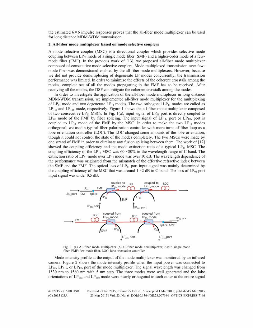
In order to investigate the application of the all-fiber mode multiplexer in long distance MDM-WDM transmission, we implemented all-fiber mode multiplexer for the multiplexing of LP01 mode and two degenerate LP11 modes. The two orthogonal LP11 modes are called as LP11a and LP11b mode, respectively. Figure 1 shows the all-fiber mode multiplexer composed of two consecutive LP11 MSCs. In Fig. 1(a), input signal of LP01 port is directly coupled to LP01 mode of the FMF by fiber splicing. The input signal of LP11a port or LP11b port is coupled to LP11 mode of the FMF by the MSC. In order to make the two LP11 modes orthogonal, we used a typical fiber polarization controller with more turns of fiber loop as a lobe orientation controller (LOC). The LOC changed some amounts of the lobe orientation, though it could not control the state of the modes completely. The two MSCs were made by one strand of FMF in order to eliminate any fusion splicing between them. The work of [12] showed the coupling efficiency and the mode extinction ratio of a typical LP11 MSC. The coupling efficiency of the LP11 MSC was 60 ~80% in the wavelength range of C-band. The extinction ratio of LP01 mode over LP11 mode was over 10 dB. The wavelength dependence of the performance was originated from the mismatch of the effective refractive index between the SMF and the FMF. The optical loss of LP11 port input signal was mainly determined by the coupling efficiency of the MSC that was around 1 ~2 dB in C-band. The loss of LP01 port input signal was under 0.5 dB.
coupled toLP11a mode
coupled toLP11b mode
LP01
LP01SMF
LP11b port
SMF splice
FMF
LP01 port
LP11a port
LP01
LOC LOC
FMF
SMF
SMF
coupled fromLP11b mode
coupled fromLP11a modeLOCLOC
splice
LP01 port
LP01 LP01
LP11a portLP11b port
Fig. 1. (a) All-fiber mode multiplexer (b) all-fiber mode demultiplexer, SMF: single-mode fiber, FMF: few-mode fiber, LOC: lobe orientation controller.
Mode intensity profile at the output of the mode multiplexer was monitored by an infrared camera. Figure 2 shows the mode intensity profile when the input power was connected to LP01, LP11a, or LP11b port of the mode multiplexer. The signal wavelength was changed from 1530 nm to 1560 nm with 5 nm step. The three modes were well generated and the lobe orientations of LP11a and LP11b mode were nearly orthogonal to each other at the entire signal
#232915 - $15.00 USD Received 21 Jan 2015; revised 27 Feb 2015; accepted 1 Mar 2015; published 9 Mar 2015 (C) 2015 OSA 23 Mar 2015 | Vol. 23, No. 6 | DOI:10.1364/OE.23.007164 | OPTICS EXPRESS 7166

wavelength. The state of the LOC was adjusted at the wavelength of 1545 nm, and then it was maintained throughout all the experiments.
The mode multiplexer can be used as the mode demultiplexer when the direction of the signal propagation is reversed. Figure 1(b) shows the all-fiber mode demultiplexer which demultiplexes LP01, LP11a, and LP11b modes. The LP11 mode in the FMF is coupled to LP01 mode of LP11a or LP11b port by the MSC. The LP01 mode in the FMF is directly coupled to LP01 mode of SMF. The LOC between the two MSCs was adjusted by monitoring the mode intensity profile as the same way as shown in Fig. 2.
Fig. 2. Output mode intensity profiles of the all-fiber mode multiplexer when signal power was launched to each of input ports of LP01, LP11a, or LP11b mode, respectively.
3. Experimental set-up
Long distance MDM-WDM transmission using the all-fiber mode multiplexers was studied with the measurement set-up shown in Fig. 3. Thirty two WDM channels in C-band (1537.40- 1562.23 nm) with a 100 GHz spacing were generated by distributed feedback lasers (DFBs). We used a tunable laser diode (TLD) with a linewidth of 100 kHz as the light source for the channel under test. Wavelength selective switch (WSS1) was used to equalize the power of all wavelength channels. The resulting 32 wavelength channels were modulated by an IQ-modulator that was driven by two independent 30 Gbaud De Bruijn bit sequences of 215-length. The sequences were generated by a digital-to-analog converter (DAC) operating at a sampling rate of 60 GS/s. The out signal of the IQ-modulator was split and combined again by a polarization beam combiner (PBC) with a delay of 382 nsec between the orthogonal polarizations. The resulting 120 Gb/s PDM (polarization division multiplexed)-QPSK was further split into three copies of the signal with a relative delay of 0, 40, and 112 nsec. The delayed signals were fed into 3-fold recirculating loops. Inside the loop, the three signals were launched into and coupled out of FMF span by the all-fiber mode multiplexer and demultiplexer described in Fig. 1.
The FMF used in the experiments supported the propagation of the linear modes of LP01 and two-fold degenerate LP11. The fiber characteristics were explained in [14]. In order to compensate modal differential group delay (MDGD) between the LP01 and LP11 in the transmission span, we used four FMF spools with lengths of 12.5, 25, 12.5, and 20 km that had different MDGDs of −1.15, + 1.64, −2.0, and + 1.52 nsec, respectively. They were connected by a commercial fusion splicer, and the overall MDGD of the 70 km FMF was ~0.01 nsec. The FMF was directly connected to the mode multiplexer and the mode demultiplexer by fusion splicing.
After the mode demultiplexer, the signals were separately amplified by three Erbium doped fiber amplifiers (EDFAs). Wavelength blockers (WBs) in the loops were used to flatten the optical spectrum of the WDM channels. Three loop switches operated synchronously to pass the signals in the three recirculating loops. After that, the signals were multiplexed and
#232915 - $15.00 USD Received 21 Jan 2015; revised 27 Feb 2015; accepted 1 Mar 2015; published 9 Mar 2015 (C) 2015 OSA 23 Mar 2015 | Vol. 23, No. 6 | DOI:10.1364/OE.23.007164 | OPTICS EXPRESS 7167

sent into the FMF span again. Finally, the signals were extracted from the loops and the WBs outside the loops were used to select the wavelength channel to be measured. The signals were amplified by EDFAs followed by three polarization-diversity coherent receivers (PD-CRXs). The resulting 12 high-speed electrical signals were captured by 12 channel modular digital storage oscilloscope (LeCroy LabMaster 9 Zi). The oscilloscope operated at a sampling rate of 40 GS/s with a bandwidth of 20 GHz. A second TLD was used as a local oscillator (LO) for intradyne detection scheme, which has the frequency offset within 500 MHz.
The captured 6 complex waveforms were processed off-line using the 66 MIMO digital signal processing algorithm explained in [13]. In order to estimate the 66 impulse response matrix, data-aided least mean squares (LMS) algorithms using a known test signal was used, and then it was switched to decision-directed LMS mode. Finally, bit error rate (BER) was evaluated.
Delay ~382 ns
PBC
EDFADFB
DFB
…
TLD
WS
S1
IQ-mod.
60GS/s DAC
WS
S2
Loop Switch
Loop Switch
Loop Switch
ModeMux
ModeDeMux
WB
WB
WB
WB WB WB
PD-CRX1PD-CRX2
Digital Oscilloscope(12ch, 20GHz, 40GS/s)
FMF 70km
PD-CRX3
LoadSwitch
LO
40ns
112ns
TLD
Fig. 3. Experimental set-up. TLD: tunable laser diode, DFB: distributed feedback laser, WSS: wavelength selective switch, EDFA: Erbium doped fiber amplifier, IQ Mod.: IQ modulator, DAC: digital to analog converter, PBC: polarization beam combiner, Mux: multiplexer, DeMux: demultiplexer, WB: wavelength blocker, FMF: few-mode fiber, PD-CRX: polarization diversity-coherent receiver, LO: local oscillator.
4. MDM-WDM transmission over long distance of FMF
First of all, we measured the BER performance of single wavelength transmission over single span of 70km FMF in order to examine the performance of the configuration. The experimental set-up was modified to measure the BER of the received signals with the variation of the optical signal-to-noise ratio (OSNR). The 120 Gb/s PDM-QPSK signal was combined with the output power of amplified spontaneous emission (ASE) noise source. Optical attenuator at the output of the ASE source was manipulated to adjust the OSNR. After single span of 70km FMF, the three output signals of the mode demultiplexer were directed to the receiver side.
In order to evaluate back-to-back (BtB) performance of the receiver systems, 120 Gb/s PDM-QPSK signal was received by each PD-CRX, separately, using single mode fiber only. Figure 4(a) shows the BtB measurement results by the three PD-CRXs when the signal wavelength was 1545 nm. The BER curves are plotted as a function of OSNR per polarization, which is the OSNR (0.1 nm resolution bandwidth) when the noise is co-polarized with the corresponding signal. The OSNR was measured at the transmitter side where the ASE noise was added to the signal. Three BtB measurements show that the OSNR per polarization of minimum of 14.8 dB at a BER of 10−3 within a variation of 0.25 dB. It shows that three PD-CRXs have nearly the same performance.
#232915 - $15.00 USD Received 21 Jan 2015; revised 27 Feb 2015; accepted 1 Mar 2015; published 9 Mar 2015 (C) 2015 OSA 23 Mar 2015 | Vol. 23, No. 6 | DOI:10.1364/OE.23.007164 | OPTICS EXPRESS 7168

We measured the BER performance of the received signals after transmitting over 70km of the FMF. Figures 4(b)-4(d) shows the BER measurements when the signal wavelength was tuned at 1535, 1545, and 1555 nm, respectively. Each BER curve was designated by the mode and the polarization at the transmitter side. The penalty at a BER of 10−3 compared with the results of Fig. 4(a) was less than 1.7, 1.0, and 1.6 dB, respectively, at each signal wavelength. These small OSNR penalties show that the coherent crosstalk in the FMF was successfully compensated by the 66 MIMO processing. Moreover, the all-fiber mode multiplexer and the mode demultiplexer works properly to combine and separate the LP01, LP11a, and LP11b modes to and out from the FMF.
(a) (b)
(c) (d)
-
-
-
----
11 12 13 14 15 16 17 18 19 20 21 2276
5
4
3
2
1
Bit
err
or
rate
(lo
g)
OSNR per polarization (dB)
LP01, x-pol LP01, y-pol LP11a, x-pol LP11a, y-pol LP11b, x-pol LP11b, y-pol
-
-
-
----
10 11 12 13 14 15 16 17 18 19 20 2176
5
4
3
2
1
Bit
err
or
rate
(lo
g)
OSNR per polarization (dB)
LP01, x-pol LP01, y-pol LP11a, x-pol LP11a, y-pol LP11b, x-pol LP11b, y-pol
-
-
-
----
10 11 12 13 14 15 16 17 18 19 20 2176
5
4
3
2
1
Bit
err
or
rate
(lo
g)
OSNR per polarization (dB)
LP01, x-pol LP01, y-pol LP11a, x-pol LP11a, y-pol LP11b, x-pol LP11b, y-pol
-
-
-
----
10 11 12 13 14 15 16 17 18 19 20 2176
5
4
3
2
1
Bit
err
or
rate
(lo
g)
OSNR per polarization (dB)
BtB1, x-pol BtB1, y-pol BtB2, x-pol BtB2, y-pol BtB3, x-pol BtB3, y-pol
Fig. 4. (a) 120 Gb/s PDM-QPSK signal single-mode fiber back-to-back BER curves measured by each PD-CRX separately. Each curve gives the BER of 60 Gb/s QPSK signal in each polarization. (b)-(d) BER curves after 70km of FMF transmission at the signal wavelength of (b) 1535 nm (c) 1545 nm and (d) 1555 nm, respectively.
Fig. 5. Optical spectrum of the WDM signals after 560 km transmission. Each spectrum of (a), (b) and (c) was obtained at the outputs of EDFAs in each loop. Resolution bandwidth: 0.5 nm.
The experimental set-up shown in Fig. 3 was used to investigate MDM-WDM transmission over long distance of the FMF. Thirty two WDM channels, carrying 3 modes of LP01, LP11a, and LP11b with each of 120 Gb/s PDM-QPSK signal, were transmitted over the multiple turns of the recirculating loops. Figure 5 shows the optical spectrum of the WDM signals after eight turns of the 70km FMF transmission. They were measured at the outputs of
#232915 - $15.00 USD Received 21 Jan 2015; revised 27 Feb 2015; accepted 1 Mar 2015; published 9 Mar 2015 (C) 2015 OSA 23 Mar 2015 | Vol. 23, No. 6 | DOI:10.1364/OE.23.007164 | OPTICS EXPRESS 7169

EDFAs in each loop, separately. There were some differences among the three spectra reflecting the gain and loss spectrum variation of the path in each loop.
Figure 6 shows the resulting BER curves as a function of the wavelength channels. The BERs were averaged over 3 modes of 120 Gb/s PDM-QPSK signal. The BERs of all the wavelength channels are well under the BER limit for the state-of-the-art soft-decision forward error correction (SD-FEC) [15]. A transmission distance of 560 km for 32 WDM channels at 100GHz channel spacing and a spectral efficiency of 3.0 bit/s/Hz was achieved. The experiments demonstrate that MDM-WDM optical transmission over long distance of the FMF is possible by using the all-fiber mode multiplexers.
1536 1540 1544 1548 1552 1556 1560 15645
4
3
2
1
BE
R (
log)
Wavelength (nm)
-
SD-FEC limit 1.9x10⁻²
-
-
-
-
Fig. 6. Bit error rate for 560 km transmission of 32 WDM channels obtained by averaging BERs over 3 modes of 120 Gb/s PDM-QPSK signals. SD-FEC: soft decision-forward error correction.
The impulse responses of the 66 MIMO channel were estimated by the MIMO digital signal processing. We applied the bulk chromatic dispersion compensation before the MIMO channel estimation. The algorithm implemented 66 MIMO channel estimation with a half-symbol-spaced complex-valued 512 taps of 8.53 nsec length. Figure 7 shows the four different types of impulse responses among the 36 (66) impulse responses. Figures 7(a)-7(d) show the impulse responses after 70 km FMF transmission, and Figs. 7(e)-7(h) show the results after 560 km FMF transmission after 8 turns of the loop. Figure 7(a) corresponds to the coupling that is launched into and received from the x-polarization of LP01 mode. It has strong and sharp coupling peak. Figures 7(b) and 7(c) shows the impulse responses between the LP01 and the LP11b modes in x-polarization that has wide distributed mode coupling. The width of the distributed coupling corresponds to the MDGD in each spool of 70km FMF. Small peaks in Figs. 7(b) and 7(c) is resulted from the splicing between the fiber spools. Figure 7(d) corresponds to the coupling from the x-polarization of LP11b mode. The strong peaks of Figs. 7(a) and 7(d) is located almost at the same time because the MDGD was compensated in the 70km FMF. Figures 7(e)-7(h) shows that the impulse responses are broadened after 560 km transmission. The length of the impulse response is enough for the 560 km transmission due to the MDGD compensated link.
From the 66 estimated impulse response matrix, we can obtain the system mode dependent loss (MDL) after carrying out singular value decomposition [16, 17]. The MDL was defined as MDL = max(|λm|2)/min(|λm|2) where six λm’s were the singular values. In Fig. 8, MDL is plotted as a function of the signal wavelength. The MDL was averaged over the last 5,000 symbols to reduce temporal variations. The MDL averaged over all the wavelength channel is 1.6 dB after transmitting single span of 70 km FMF. It grew to 2.9 dB at a distance of 560 km after 8 turns of the loop. It is known that the MDL in dB grows linearly with distance in general [16]. But we observed the MDL between 70km and 560km transmission is
#232915 - $15.00 USD Received 21 Jan 2015; revised 27 Feb 2015; accepted 1 Mar 2015; published 9 Mar 2015 (C) 2015 OSA 23 Mar 2015 | Vol. 23, No. 6 | DOI:10.1364/OE.23.007164 | OPTICS EXPRESS 7170

very close at some wavelengths. The characteristics of the MDL in MDM transmission system is not well known and under the study.
Figure 8 shows that the all-fiber mode multiplexers have small MDL values over wide wavelength range. The MDL measured in Fig. 8 is very similar to the MDL observed for the MDM transmission using photonic lantern based mode multiplexers in [18]. The estimated system MDL values have negligible impact on system capacity [17].
The all-fiber mode multiplexers in the experiments used the LOC to provide two orthogonal LP11 modes. The LOC can be eliminated if one of the MSC is rotated by 90° relative to the other MSC [19]. A three core MSC with one few mode core and two single mode cores can be an alternative when the two SMFs are arranged in perpendicular directions [11]. Recently, the MSC with three cores in a 3-dimensional photonic chip was demonstrated by femtosecond laser direct writing [20, 21]. The all-fiber mode multiplexer based on the MSCs could be used for mode multiplexing in long distance MDM-WDM transmission.
The transmission capacity in MDM-WDM transmission using the all-fiber mode multiplexer can be increased. The all-fiber mode multiplexer can be composed of additional higher-order mode selective couplers to multiplex more number of modes [12, 13]. Moreover, the mode selective coupler can be designed to operate in wide WDM bandwidth including L-band. It is considered that these goals will be achieved in near future.
Fig. 7. Estimated impulse responses for four different types of mode coupling at (a)-(d) 1 turn, (e)-(h) 8 turns of the loop.
#232915 - $15.00 USD Received 21 Jan 2015; revised 27 Feb 2015; accepted 1 Mar 2015; published 9 Mar 2015 (C) 2015 OSA 23 Mar 2015 | Vol. 23, No. 6 | DOI:10.1364/OE.23.007164 | OPTICS EXPRESS 7171

1536 1540 1544 1548 1552 1556 1560 15640
1
2
3
4
5
MD
L (d
B)
Wavelength (nm)
70km - 1 turn of the loop 560km - 8 turns of the loop
Fig. 8. System mode dependent loss (MDL) evaluated from the estimated impulse responses for 32 wavelength channels.
5. Conclusions
In this work, we proposed the all-fiber mode multiplexer that combines LP01 and two-fold degenerate LP11 modes. We have successfully demonstrated MDM-WDM transmission over 560 km of FMF with 3 modes and 32 wavelength channels by using the all-fiber mode multiplexers. It was shown that the all-fiber mode multiplexers could be a crucial building block for long distance MDM-WDM optical transmission.
Acknowledgments
This work was supported by the IT R&D program of MSIP/IITP, Republic of Korea. [10043383, Research of mode-division-multiplexing optical transmission technology over 10 km multi-mode fiber]
#232915 - $15.00 USD Received 21 Jan 2015; revised 27 Feb 2015; accepted 1 Mar 2015; published 9 Mar 2015 (C) 2015 OSA 23 Mar 2015 | Vol. 23, No. 6 | DOI:10.1364/OE.23.007164 | OPTICS EXPRESS 7172