Embed Size (px)
Citation preview
1 of 10
Optimum Technology Matching® Applied
GaAs HBT
InGaP HBTGaAs MESFET
SiGe BiCMOSSi BiCMOSSiGe HBT
GaAs pHEMTSi CMOSSi BJT
GaN HEMT
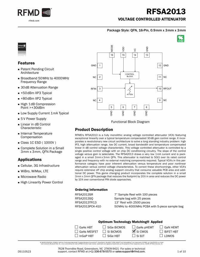
Functional Block Diagram
RF MICRO DEVICES®, RFMD®, Optimum Technology Matching®, Enabling Wireless Connectivity™, PowerStar®, POLARIS™ TOTAL RADIO™ and UltimateBlue™ are trademarks of RFMD, LLC. BLUETOOTH is a trade-mark owned by Bluetooth SIG, Inc., U.S.A. and licensed for use by RFMD. All other trade names, trademarks and registered trademarks are the property of their respective owners. ©2006, RF Micro Devices, Inc.
Product Description
7628 Thorndike Road, Greensboro, NC 27409-9421 · For sales or technical support, contact RFMD at (+1) 336-678-5570 or [email protected].
Ordering Information
BiFET HBTLDMOS
4
CONTROLBLOCK
ATTEN
RFIN RFOUT
VC
VDD
MODE
5
3
2
1
6 7 8
9
10
11
12
13141516
GND
NC
NC
GND
GND
GND
GND
NC
NC
GND
GND
RFSA2013VOLTAGE CONTROLLED ATTENUATOR
RFMD's RFSA2013 is a fully monolithic analog voltage controlled attenuator (VCA) featuringexceptional linearity over a typical temperature compensated 30dB gain control range. It incor-porates a revolutionary new circuit architecture to solve a long standing industry problem: highIP3, high attenuation range, low DC current, broad bandwidth and temperature compensatedlinear in dB control voltage characteristic. This voltage controlled attenuator is controlled by asingle positive control voltage with on chip DC conditioning circuitry. The slope of the controlvoltage versus gain is selectable. The RFSA2013 draws a very low 1mA current and is pack-aged in a small 3mm x 3mm QFN. This attenuator is matched to 50 over its rated controlrange and frequency with no external matching components required. Typical VCA's in this per-formance category have poor inherent attenuation versus temperature and poor nonlinearattenuation versus control voltage characteristics. To correct these shortcomings, other VCA'srequire extensive off chip analog support circuitry that consume valuable PCB area and addi-tional DC power. This game changing product incorporates the complete solution in a small3mm x 3mm QFN package that reduces the footprint by 20X in area and reduces the DC powerby 10X over conventional PIN diode approaches.
Features Patent Pending Circuit
Architecture
Broadband 50MHz to 4000MHz Frequency Range
30dB Attenuation Range
+50dBm IIP3 Typical
+80dBm IIP2 Typical
High 1dB Compression Point >+30dBm
Low Supply Current 1mA Typical
5 V Power Supply
Linear in dB Control Characteristic
Internal Temperature Compensation
Class 1C ESD ( 1000V )
Complete Solution in a Small 3mm x 3mm, QFN Package
Applications Cellular, 3G Infrastructure
WiBro, WiMax, LTE
Microwave Radio
High Linearity Power Control
DS110523
Package Style: QFN, 16-Pin, 0.9mm x 3mm x 3mm
RFSA2013Voltage Con-trolled Attenu-ator
RFSA2013SR 7” Sample Reel with 100 piecesRFSA2013SQ Sample bag with 25 piecesRFSA2013TR13 13” Reel with 2500 piecesRFSA2013PCK-410 50MHz to 4000MHz PCBA with 5-piece sample bag

2 of 10
RFSA2013
DS1105237628 Thorndike Road, Greensboro, NC 27409-9421 · For sales or technical support, contact RFMD at (+1) 336-678-5570 or [email protected].
Absolute Maximum Ratings
Parameter Rating UnitSupply Voltage 6 V
RF Input Power +30 dBm
Operating Temperature -40 to +85 °C
Storage Temperature -65 to +150 °C
Junction Temperature +125 °C
ESD Rating (HBM) 1000 V
ParameterSpecification
Unit ConditionMin. Typ. Max.
GeneralSupply Voltage 4.75 5 5.25 V
Supply Current 1 mA
Operating Temperature -40 85 °C
Thermal Resistance 45 °C/W
RF Input Power 27 dBm
RF PerformanceFrequency Range 50 4000 MHz
Minimum Insertion Loss 2.6 3.5 dB
Gain Control Range 30 33.2 dB
Gain vs. Temperature 1.7 dB Peak to peak gain variation over temperature for fixed control voltage
Return Loss 15 dB
Input 1dB Compression Point 30 dBm
Input IP3 45 50 dBm PIN + (IM3dBC/2)
Input IP2 80 dBm PIN + IM2dBC, IM2 is F1+F2
Input IH2 85 dBm PIN + H2dBC, H2 is second harmonic
Input IH3 55 dBm PIN + (H3dBC/2), H3 is third harmonic
ControlVoltage Control Range, Positive Attenuation
Slope0.5 4.5 V 4.5V control voltage is lowest insertion loss,
MODE pin high
Voltage Control Range, Negative Attenuation Slope
0 3.3 V 0V control voltage is lowest insertion loss, MODE pin low
MODE Pin Logic Low 0.4 V
MODE Pin Logic High 1 V
Settling Time 25 usec Min attenuation setting to Max attenuation setting within 0.5dB
Note: Typical performance at nominal conditions unless otherwise noted: Supply voltage=5.0V, Operating temperature=25°C, RF Frequency 2GHz
Caution! ESD sensitive device.Exceeding any one or a combination of the Absolute Maximum Rating conditions may cause permanent damage to the device. Extended application of Absolute Maximum Rating conditions to the device may reduce device reliability. Specified typical perfor-mance or functional operation of the device under Absolute Maximum Rating condi-tions is not implied.
The information in this publication is believed to be accurate and reliable. However, no responsibility is assumed by RF Micro Devices, Inc. ("RFMD") for its use, nor for any infringement of patents, or other rights of third parties, resulting from its use. No license is granted by implication or otherwise under any patent or patent rights of RFMD. RFMD reserves the right to change component circuitry, recommended appli-cation circuitry and specifications at any time without prior notice.
RFMD Green: RoHS compliant per EU Directive 2002/95/EC, halogen free per IEC 61249-2-21, < 1000ppm each of antimony trioxide in polymeric materials and red phosphorus as a flame retardant, and <2% antimony in solder.

3 of 10
RFSA2013
DS1105237628 Thorndike Road, Greensboro, NC 27409-9421 · For sales or technical support, contact RFMD at (+1) 336-678-5570 or [email protected].
Measured Positive Attenuation Slope Performance
-30
-25
-20
-15
-10
-5
0
S21
(dB)
Inser�on Loss vs VCRFSA2013,RF 2GHz, Vdd=5V
25C
-40C -30
-25
-20
-15
-10
-5
0
S21
(dB)
Inser�on Loss vs Frequency RFSA2013, Vdd 5V, Temp=+25c
VC=0V
VC=0.5V
VC=1.0V
VC=1.5V
VC=2.0V
VC=2.5V
VC=3.0V
VC=3.5V
-50
-45
-40
-35
-30
-25
-20
-15
-10
-5
0
0 0.5 1 1.5 2 2.5 3 3.5 4 4.5 5
S21
(dB)
VC (V)
Inser�on Loss vs VCRFSA2013,RF 2GHz, Vdd=5V
25C
-40C
85C
-50
-45
-40
-35
-30
-25
-20
-15
-10
-5
0
0 0.5 1 1.5 2 2.5 3 3.5 4 4.5 5 5.5 6
S21
(dB)
Frequency (GHz)
Inser�on Loss vs Frequency RFSA2013, Vdd 5V, Temp=+25c
VC=0V
VC=0.5V
VC=1.0V
VC=1.5V
VC=2.0V
VC=2.5V
VC=3.0V
VC=3.5V
VC=4.0V
VC=4.5V
VC=5.0V
0
Input Return Loss vs VCRFSA2013,RF 2GHz, Vdd=5V
0
Output Return Loss vs VCRFSA2013, RF 2GHz, Vdd=5V
-50
-45
-40
-35
-30
-25
-20
-15
-10
-5
0
0 0.5 1 1.5 2 2.5 3 3.5 4 4.5 5
S21
(dB)
VC (V)
Inser�on Loss vs VCRFSA2013,RF 2GHz, Vdd=5V
25C
-40C
85C
-50
-45
-40
-35
-30
-25
-20
-15
-10
-5
0
0 0.5 1 1.5 2 2.5 3 3.5 4 4.5 5 5.5 6
S21
(dB)
Frequency (GHz)
Inser�on Loss vs Frequency RFSA2013, Vdd 5V, Temp=+25c
VC=0V
VC=0.5V
VC=1.0V
VC=1.5V
VC=2.0V
VC=2.5V
VC=3.0V
VC=3.5V
VC=4.0V
VC=4.5V
VC=5.0V
-45
-40
-35
-30
-25
-20
-15
-10
-5
0
S11
(dB)
Input Return Loss vs VCRFSA2013,RF 2GHz, Vdd=5V
25C
-40C
85C
-45
-40
-35
-30
-25
-20
-15
-10
-5
0S2
2 (d
B)
Output Return Loss vs VCRFSA2013, RF 2GHz, Vdd=5V
25C
-40C
85C
-50
-45
-40
-35
-30
-25
-20
-15
-10
-5
0
0 0.5 1 1.5 2 2.5 3 3.5 4 4.5 5
S21
(dB)
VC (V)
Inser�on Loss vs VCRFSA2013,RF 2GHz, Vdd=5V
25C
-40C
85C
-50
-45
-40
-35
-30
-25
-20
-15
-10
-5
0
0 0.5 1 1.5 2 2.5 3 3.5 4 4.5 5 5.5 6
S21
(dB)
Frequency (GHz)
Inser�on Loss vs Frequency RFSA2013, Vdd 5V, Temp=+25c
VC=0V
VC=0.5V
VC=1.0V
VC=1.5V
VC=2.0V
VC=2.5V
VC=3.0V
VC=3.5V
VC=4.0V
VC=4.5V
VC=5.0V
-50
-45
-40
-35
-30
-25
-20
-15
-10
-5
0
0 0.5 1 1.5 2 2.5 3 3.5 4 4.5 5
S11
(dB)
VC (V)
Input Return Loss vs VCRFSA2013,RF 2GHz, Vdd=5V
25C
-40C
85C
-50
-45
-40
-35
-30
-25
-20
-15
-10
-5
0
0 0.5 1 1.5 2 2.5 3 3.5 4 4.5 5
S22
(dB)
VC (V)
Output Return Loss vs VCRFSA2013, RF 2GHz, Vdd=5V
25C
-40C
85C
-30
-25
-20
-15
-10
-5
0
S21
(dB)
Inser�on Loss vs VCRFSA2013,RF 2GHz, Vdd=5V
25C
-40C -30
-25
-20
-15
-10
-5
0
S21
(dB)
Inser�on Loss vs Frequency RFSA2013, Vdd 5V, Temp=+25c
VC=0V
VC=0.5V
VC=1.0V
VC=1.5V
VC=2.0V
VC=2.5V
VC=3.0V
VC=3.5V
-50
-45
-40
-35
-30
-25
-20
-15
-10
-5
0
0 0.5 1 1.5 2 2.5 3 3.5 4 4.5 5
S21
(dB)
VC (V)
Inser�on Loss vs VCRFSA2013,RF 2GHz, Vdd=5V
25C
-40C
85C
-50
-45
-40
-35
-30
-25
-20
-15
-10
-5
0
0 0.5 1 1.5 2 2.5 3 3.5 4 4.5 5 5.5 6
S21
(dB)
Frequency (GHz)
Inser�on Loss vs Frequency RFSA2013, Vdd 5V, Temp=+25c
VC=0V
VC=0.5V
VC=1.0V
VC=1.5V
VC=2.0V
VC=2.5V
VC=3.0V
VC=3.5V
VC=4.0V
VC=4.5V
VC=5.0V
0
Input Return Loss vs VCRFSA2013,RF 2GHz, Vdd=5V
0
Output Return Loss vs VCRFSA2013, RF 2GHz, Vdd=5V
-50
-45
-40
-35
-30
-25
-20
-15
-10
-5
0
0 0.5 1 1.5 2 2.5 3 3.5 4 4.5 5
S21
(dB)
VC (V)
Inser�on Loss vs VCRFSA2013,RF 2GHz, Vdd=5V
25C
-40C
85C
-50
-45
-40
-35
-30
-25
-20
-15
-10
-5
0
0 0.5 1 1.5 2 2.5 3 3.5 4 4.5 5 5.5 6
S21
(dB)
Frequency (GHz)
Inser�on Loss vs Frequency RFSA2013, Vdd 5V, Temp=+25c
VC=0V
VC=0.5V
VC=1.0V
VC=1.5V
VC=2.0V
VC=2.5V
VC=3.0V
VC=3.5V
VC=4.0V
VC=4.5V
VC=5.0V
-45
-40
-35
-30
-25
-20
-15
-10
-5
0
S11
(dB)
Input Return Loss vs VCRFSA2013,RF 2GHz, Vdd=5V
25C
-40C
85C
-45
-40
-35
-30
-25
-20
-15
-10
-5
0S2
2 (d
B)
Output Return Loss vs VCRFSA2013, RF 2GHz, Vdd=5V
25C
-40C
85C
-50
-45
-40
-35
-30
-25
-20
-15
-10
-5
0
0 0.5 1 1.5 2 2.5 3 3.5 4 4.5 5
S21
(dB)
VC (V)
Inser�on Loss vs VCRFSA2013,RF 2GHz, Vdd=5V
25C
-40C
85C
-50
-45
-40
-35
-30
-25
-20
-15
-10
-5
0
0 0.5 1 1.5 2 2.5 3 3.5 4 4.5 5 5.5 6
S21
(dB)
Frequency (GHz)
Inser�on Loss vs Frequency RFSA2013, Vdd 5V, Temp=+25c
VC=0V
VC=0.5V
VC=1.0V
VC=1.5V
VC=2.0V
VC=2.5V
VC=3.0V
VC=3.5V
VC=4.0V
VC=4.5V
VC=5.0V
-50
-45
-40
-35
-30
-25
-20
-15
-10
-5
0
0 0.5 1 1.5 2 2.5 3 3.5 4 4.5 5
S11
(dB)
VC (V)
Input Return Loss vs VCRFSA2013,RF 2GHz, Vdd=5V
25C
-40C
85C
-50
-45
-40
-35
-30
-25
-20
-15
-10
-5
0
0 0.5 1 1.5 2 2.5 3 3.5 4 4.5 5
S22
(dB)
VC (V)
Output Return Loss vs VCRFSA2013, RF 2GHz, Vdd=5V
25C
-40C
85C
-50
-45
-40
-35
-30
-25
-20
-15
-10
-5
0
0 0.5 1 1.5 2 2.5 3 3.5 4 4.5 5
S21
(dB)
VC (V)
Inser�on Loss vs VCRFSA2013,RF 2GHz, Vdd=5V
25C
-40C
85C
-50
-45
-40
-35
-30
-25
-20
-15
-10
-5
0
0 0.5 1 1.5 2 2.5 3 3.5 4 4.5 5 5.5 6
S21
(dB)
Frequency (GHz)
Inser�on Loss vs Frequency RFSA2013, Vdd 5V, Temp=+25c
VC=0V
VC=0.5V
VC=1.0V
VC=1.5V
VC=2.0V
VC=2.5V
VC=3.0V
VC=3.5V
VC=4.0V
VC=4.5V
VC=5.0V
-50
-45
-40
-35
-30
-25
-20
-15
-10
-5
0
0 0.5 1 1.5 2 2.5 3 3.5 4 4.5 5
S11
(dB)
VC (V)
Input Return Loss vs VCRFSA2013,RF 2GHz, Vdd=5V
25C
-40C
85C
-50
-45
-40
-35
-30
-25
-20
-15
-10
-5
0
0 0.5 1 1.5 2 2.5 3 3.5 4 4.5 5
S22
(dB)
VC (V)
Output Return Loss vs VCRFSA2013, RF 2GHz, Vdd=5V
25C
-40C
85C
-50
-45
-40
-35
-30
-25
-20
-15
-10
-5
0
0 0.5 1 1.5 2 2.5 3 3.5 4 4.5 5
S21
(dB)
VC (V)
Inser�on Loss vs VCRFSA2013,RF 2GHz, Vdd=5V
25C
-40C
85C
-50
-45
-40
-35
-30
-25
-20
-15
-10
-5
0
0 0.5 1 1.5 2 2.5 3 3.5 4 4.5 5 5.5 6
S21
(dB)
Frequency (GHz)
Inser�on Loss vs Frequency RFSA2013, Vdd 5V, Temp=+25c
VC=0V
VC=0.5V
VC=1.0V
VC=1.5V
VC=2.0V
VC=2.5V
VC=3.0V
VC=3.5V
VC=4.0V
VC=4.5V
VC=5.0V
-50
-45
-40
-35
-30
-25
-20
-15
-10
-5
0
0 0.5 1 1.5 2 2.5 3 3.5 4 4.5 5
S11
(dB)
VC (V)
Input Return Loss vs VCRFSA2013,RF 2GHz, Vdd=5V
25C
-40C
85C
-50
-45
-40
-35
-30
-25
-20
-15
-10
-5
0
0 0.5 1 1.5 2 2.5 3 3.5 4 4.5 5
S22
(dB)
VC (V)
Output Return Loss vs VCRFSA2013, RF 2GHz, Vdd=5V
25C
-40C
85C
-50
-45
-40
-35
-30
-25
-20
-15
-10
-5
0
0 0.5 1 1.5 2 2.5 3 3.5 4 4.5 5
S21
(dB)
VC (V)
Inser�on Loss vs VCRFSA2013,RF 2GHz, Vdd=5V
25C
-40C
85C
-50
-45
-40
-35
-30
-25
-20
-15
-10
-5
0
0 0.5 1 1.5 2 2.5 3 3.5 4 4.5 5 5.5 6
S21
(dB)
Frequency (GHz)
Inser�on Loss vs Frequency RFSA2013, Vdd 5V, Temp=+25c
VC=0V
VC=0.5V
VC=1.0V
VC=1.5V
VC=2.0V
VC=2.5V
VC=3.0V
VC=3.5V
VC=4.0V
VC=4.5V
VC=5.0V
-50
-45
-40
-35
-30
-25
-20
-15
-10
-5
0
0 0.5 1 1.5 2 2.5 3 3.5 4 4.5 5
S11
(dB)
VC (V)
Input Return Loss vs VCRFSA2013,RF 2GHz, Vdd=5V
25C
-40C
85C
-50
-45
-40
-35
-30
-25
-20
-15
-10
-5
0
0 0.5 1 1.5 2 2.5 3 3.5 4 4.5 5
S22
(dB)
VC (V)
Output Return Loss vs VCRFSA2013, RF 2GHz, Vdd=5V
25C
-40C
85C
-50
-45
-40
-35
-30
-25
-20
-15
-10
-5
0
0 0.5 1 1.5 2 2.5 3 3.5 4 4.5 5
S21
(dB)
VC (V)
Inser�on Loss versus VCRFSA2013,RF 2GHz, Vdd=5V
25C
-40C
85C
-50
-45
-40
-35
-30
-25
-20
-15
-10
-5
0
0 0.5 1 1.5 2 2.5 3 3.5 4 4.5 5 5.5 6
S21
(dB)
Frequency (GHz)
Inser�on Loss versus Frequency RFSA2013, Vdd 5V, Temp=+25c
VC=0V
VC=0.5V
VC=1.0V
VC=1.5V
VC=2.0V
VC=2.5V
VC=3.0V
VC=3.5V
VC=4.0V
VC=4.5V
VC=5.0V
-50
-45
-40
-35
-30
-25
-20
-15
-10
-5
0
0 0.5 1 1.5 2 2.5 3 3.5 4 4.5 5
S11
(dB)
VC (V)
Input Return Loss versus VCRFSA2013,RF 2GHz, Vdd=5V
25C
-40C
85C
-50
-45
-40
-35
-30
-25
-20
-15
-10
-5
0
0 0.5 1 1.5 2 2.5 3 3.5 4 4.5 5
S22
(dB)
VC (V)
Output Return Loss versus VCRFSA2013, RF 2GHz, Vdd=5V
25C
-40C
85C

4 of 10
RFSA2013
DS1105237628 Thorndike Road, Greensboro, NC 27409-9421 · For sales or technical support, contact RFMD at (+1) 336-678-5570 or [email protected].
Measured Positive Attenuation Slope Performance
0
10
20
30
40
50
60
70
-40 -35 -30 -25 -20 -15 -10 -5 0
IIP3
(dBm
)
S21 (dB)
Input IP3 versus AttenuationRFSA2013, RF 2GHz Vdd=5V, Pin=+20dBm/tone
25C
-40C
85C
50
55
60
65
70
75
80
85
90
95
100
105
0 0.5 1 1.5 2 2.5 3 3.5 4 4.5 5
IIP2
(dBm
)
VC (V)
Input IP2 versus VCRFSA2013, RF 2GHz, Vdd=5V, Pin=+20dBm/tone
25C
-40C
85C
35
40
45
50
55
60
65
70
75
0 0.5 1 1.5 2 2.5 3 3.5 4 4.5 5
IH3
(dBm
)
VC (V)
3rd Harmonic IH3 versus VCRFSA2013, RF 2GHz, Vdd=5V, Pin=+20dBm
25C
-40C
85C
60
65
70
75
80
85
90
95
100
0 0.5 1 1.5 2 2.5 3 3.5 4 4.5 5
IH2
(dBm
)
VC (V)
2nd Harmonic IH2 versus VCRFSA2013, RF 2 GHz, Vdd=5V, Pin=+20dBm
25C
-40C
85C

5 of 10
RFSA2013
DS1105237628 Thorndike Road, Greensboro, NC 27409-9421 · For sales or technical support, contact RFMD at (+1) 336-678-5570 or [email protected].
Measured Negative Attenuation Slope Performance
-50
-45
-40
-35
-30
-25
-20
-15
-10
-5
0
0 0.5 1 1.5 2 2.5 3 3.5 4
S21
(dB)
VC (V)
Insertion Loss versus VCRFSA2013, RF 2GHz, Vdd=5V
25C
-40C
85C
-50
-45
-40
-35
-30
-25
-20
-15
-10
-5
0
0 0.5 1 1.5 2 2.5 3 3.5 4 4.5 5 5.5 6
S21
(dB)
Frequency (GHz)
Insertion Loss versus Frequency RFSA2013, VDD=5V, Temp=+25c
VC=0V
VC=0.5V
VC=1.0V
VC=1.5V
VC=2.0V
VC=2.5V
VC=3.0V
VC=3.5V
VC=4.0V
-50
-45
-40
-35
-30
-25
-20
-15
-10
-5
0
0 0.5 1 1.5 2 2.5 3 3.5 4
S11
(dB)
VC (V)
Input Return Loss versus VCRFSA2013, RF 2GHz, VDD=5V
25C
-40C
85C
-50
-45
-40
-35
-30
-25
-20
-15
-10
-5
0
0 0.5 1 1.5 2 2.5 3 3.5 4
S22
(dB)
VC (V)
Output Return Loss versus VCRFSA2013, RF 2GHz, Vdd=5V
25C
-40C
85C

6 of 10
RFSA2013
DS1105237628 Thorndike Road, Greensboro, NC 27409-9421 · For sales or technical support, contact RFMD at (+1) 336-678-5570 or [email protected].
Measured Negative Attenuation Slope Performance
0
10
20
30
40
50
60
70
-40 -35 -30 -25 -20 -15 -10 -5 0
IIP3
(dBm
)
S21 (dB)
Input IP3 versus AttenuationRFSA2013, RF 2GHz, Vdd=5V, Pin=+20dBm/tone
25C
-40C
85C
50
55
60
65
70
75
80
85
90
95
100
105
0 0.5 1 1.5 2 2.5 3 3.5 4
IIP2
(dBm
)
VC (V)
Input IP2 versus VCRFSA2013, RF 2GHz, Vdd=5V, Pin=+20dBm/tone
25C
-40C
85C
35
40
45
50
55
60
65
70
75
0 0.5 1 1.5 2 2.5 3 3.5 4
IH3
(dBm
)
VC (V)
3rd Harmonic IH3 versus VCRFSA2013, RF 2GHz, Vdd=5V, Pin=+20dBm
25C
-40C
85C
60
65
70
75
80
85
90
95
100
0 0.5 1 1.5 2 2.5 3 3.5 4
IH2
(dBm
)
VC (V)
2nd Harmonic IH2 versus VCRFSA2013, RF 2GHz, Vdd=5V, Pin=+20dBm
25C
-40C
85C

7 of 10
RFSA2013
DS1105237628 Thorndike Road, Greensboro, NC 27409-9421 · For sales or technical support, contact RFMD at (+1) 336-678-5570 or [email protected].
PCB Patterns
Thermal vias for center slug “C” should be incorporated into the PCB design. The number and size of thermal vias will depend on the application, the power dissipationand the electrical requirements. Example of the number and size of vias can be found on the RFMD evaluation board layout.
Pin Names and DescriptionsPin Function Description1 GND Ground Pin2 NC No Connection. Do Not Connect to PC Board Ground Plane.3 RFIN RF Input. Use External DC Block.4 NC No Connection. Do Not Connect to PC Board Ground Plane.5 GND Ground Pin6 GND Ground Pin Can Be Left Floating on PC Board7 GND Ground Pin Can Be Left Floating on PC Board8 GND Ground Pin9 NC No Connection. Do Not Connect to PC Board Ground Plane.
10 RFOUT RF Output. Use External DC Block.11 NC No Connection. Do Not Connect to PC Board Ground Plane.12 GND Ground Pin13 GND Ground Pin14 VC Attenuator Control Voltage15 VDD Supply Voltage (5V)16 MODE Attenuation Slope Control
Connect to GND to Enable Negative Attenuation SlopeConnect to VDD to Enable Positive Attenuation Slope
GND GND Exposed Package Ground Paddle is RF and DC Ground
PCB STENCIL PATTERN
A A
B
BC
A A
B
B
PCB SOLDER MASK PATTERNPCB METALPATTERN
A = 0.260 x 0.528 (mm) TypB = 0.528 x 0.260 (mm) TypC = 1.700 x 1.700 (mm) 15% Rounded Rectangle
A A
B
B
A A
B
B
A = 0.380 x 0.648 (mm) TypB = 0.648 x 0.380 (mm) TypC = 1.820 x 1.820 (mm) 15% Rounded Rectangle
16x 0.250
A = 0.234 x 0.475 (mm) TypB = 0.475 x 0.234 (mm) TypC = 1.530 x 1.530 (mm) 15% Rounded Rectangle
4x 1.364
2x 0.250
2x 0.250
2x 0.750
4x 1.364
4x 1
.364
4x 1
.364
2x 0
.750
2x 0
.250
2x 0
.250
2x 0
.750
2x 0.750
0.000
0.00
0
A A
B
BC
A A
B
B
12x 0.266
A A
B
B
A A
B
B
16x 0.361
4x 1.364
2x 0.250
2x 0.250
2x 0.750
4x 1.364
4x 1
.364
4x 1
.364
2x 0
.750
2x 0
.250
2x 0
.250
2x 0
.750
2x 0.750
0.000
0.00
0
A A
B
BC
A A
B
B
12x 0.120
A A
B
B
A A
B
B
16x 0.130
4x 1.364
2x 0.250
2x 0.250
2x 0.750
4x 1.364
4x 1
.364
4x 1
.364
2x 0
.750
2x 0
.250
2x 0
.250
2x 0
.750
2x 0.750
0.000
0.00
0

8 of 10
RFSA2013
DS1105237628 Thorndike Road, Greensboro, NC 27409-9421 · For sales or technical support, contact RFMD at (+1) 336-678-5570 or [email protected].
Evaluation Board Schematic
RFSA20133
2
4
1
10
11
9
12
15 1416 13
6 75 8
C11000pF
C21000pF
C91000pF
MODE
VDD
VC
RFIN RFOUT
R5100
C41uF

9 of 10
RFSA2013
DS1105237628 Thorndike Road, Greensboro, NC 27409-9421 · For sales or technical support, contact RFMD at (+1) 336-678-5570 or [email protected].
Evaluation Board Assembly Drawing
Evaluation Board Bill of Materials (BOM)
Notes:1. Manufacturers' P/Ns are subject to change by the manufacturers following the issue of this document and are thereby included for reference only.2. Contact RFMD Corporate Engineering Materials with questions regarding specific Manufacturers' P/Ns.
Description Reference Designator Manufacturer Manufacturer’s P/N
Voltage Controlled Attenuator VCA, 5V U1 RFMD RFSA2013
CONN, SMA, END LNCH, MINI, FLT, 0.068” J1, J2 Emerson Network Power 142-0741-851
CONN, HDR, SR, 4-PIN, 0.100”, T/H‘ P1 MOLEX 22-28-4043
PCB, SA2013-410 DDI SA2013-410
CAP, 1000pF, 10%, 25V, X7R, 0402 C1, C2, C9 Murata Electronics GRM155R71H102KA01D
CAP, 1F, 10%, 16V, X7R, 1206 C4 Murata Electronics GRM31MR71E105KC01L
RES, 100, 5%, 1/16W, 0402 R5 Kamaya, Inc RMC1/16S-101JTH
DNP C3, C5, C6, C7, C8 N/A N/A
DNP R1, R2, R3, R4 N/A N/A
DNP P2 N/A N/A

10 of 10
RFSA2013
DS1105237628 Thorndike Road, Greensboro, NC 27409-9421 · For sales or technical support, contact RFMD at (+1) 336-678-5570 or [email protected].
Package Drawing
Branding Diagram
3.000±0.100
3.000±0.100
0.203 Ref
0.850±.050
1.700±0.100
1.700±0.100
0.500 BSC
0.400±.050
0.250 +0.050 / -0.070
Pin 1 IndicatorTrace Code to be assigned by SubCon
20132013