Embed Size (px)
Citation preview

Models 1839Forma Laminar Airflow Workstation Class 100Operating and Maintenance Manual 7001839 Rev. 6
Visit us online to register your warrantywww.thermoscientific.com/labwarranty
Thermo ScientificThermo Scientific
MANUAL NUMBER 7001839
6 29120 9/25/12 Added note for online warranty ccs
5 25439/HD-1597 3/27/09 Added required UL info ccs
4 23871/SI-9779 4/3/07 Black 460022 outlet (low volume) replaced by white 460024, schematics ccs
3 21732/HD-1464 8/15/05 Updated parts list ccs
-- 21077/HD-1376 9/20/02 Removed certifiers list , added reference to website ccs
2 19029/HD-1295 6/19/00 Changed 9 FLA on schematic to 4 with exclusion ccs
1 18826/HD-1286 2/25/00 Added mercury disposal warning ccs
-- 18582/HD-1269 11/4/99 Added air flow test sheet to Certification Testing Procedures section ccs
-- -- 7/99 Revised Specifications Section 10 aks
0 -- 3/95 Standard Manual
REV ECR/ECN DATE DESCRIPTION By
Preface
Lam Flow Workstation i
A printed copy of the operating manual is available from Technical Services.

Thermo Scientificii Lam Flow Workstation Thermo Scientific
Preface
Important Read this instruction manual. Failure to read, understand and follow the instructions in this manualmay result in damage to the unit, injury to operating personnel, and poor equipment performance. s
Caution All internal adjustments and maintenance must be performed by qualified service personnel. s
Warning Lamps, thermometers, and thermoregulators contain mercury. Do not put in trash. Recycle ordispose as hazardous waste. s
Material in this manual is for information purposes only. The contents and the product it describes are subjectto change without notice. Thermo Scientific makes no representations or warranties with respect to thismanual. In no event shall Thermo be held liable for any damages, direct or incidental, arising out of or relatedto the use of this manual.
©1995 Thermo Scientific. All rights reserved.

Thermo Scientific Lam Flow Workstation iiiThermo Scientific
Preface
Important operating and/or maintenance instructions. Read the accompanying text carefully.
Potential electrical hazards. Only qualified persons should perform procedures associated with thissymbol.
Potential biological hazards. Proper protective equipment and procedures must be used when followinginstructions associated with this sysmbol. Referencee O.S.H.A. Regulation 1910-1030.
Equipment being maintained or serviced must be turned off and locked off to prevent possible injury.
Skin damage and/or eye injury can result from the light produced by ultraviolet light (UV) sourcesinstalled in this equipment. Never work in this unit with the UV light operating.
Marking of electrical and electronic equipment, which applies to electrical and electronic equipmentfalling under the Directive 2002/96/EC (WEEE) and the equipment that has been put on the marketafter 13 August 2005.
This product is required to comply with the European Union’s Waste Electrical & ElectronicEquipment (WEEE) Directive 2002/96/EC. It is marked with the WEEE symbol. Thermo Scientifichas contracted with one or more recycling/disposal companies in each EU Member State EuropeanCountry, and this product should be disposed of or recycled through them. Further information onThermo’s compliance with this directive, the recyclers in your country and information on Thermoproducts will be available at www.thermofisher.com.
4 Always use the proper protective equipment (clothing, gloves, goggles, etc.)
4 Always dissipate extreme cold or heat and wear protective clothing.
4 Always follow good hygiene practices.
4 Each individual is responsible for his or her own safety.
Thermo Scientificiv Lam Flow Workstation Thermo Scientific
Preface
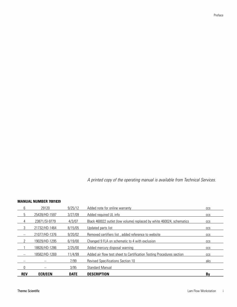
Do You Need Information or Assistance on
Thermo Scientific Products?
If you do, please contact us 8:00 a.m. to 6:00 p.m. (Eastern Time) at:
1-740-373-4763 Direct
1-800-438-4851 Toll Free, U.S. and Canada
1-877-213-8051 FAX
http://www.thermoscientific.com Internet Worldwide Web Home Page
[email protected] Tech Support Email Address
Certified Service Web Page
Thermo Fisher Scientific
401 Millcreek Road, Box 649
Marietta, OH 45750
Our staff can provide information on pricing and give you quotations. We can
take your order and provide delivery information on major equipment items or make
arrangements to have your local sales representative contact you. Our products are listed on the
Internet and we can be contacted through our Internet home page.
Our staff can supply technical information about proper setup, operation or
troubleshooting of your equipment. We can fill your needs for spare or replacement parts or
provide you with on-site service. We can also provide you with a quotation on our Extended
Warranty for your Thermo Scientific products.
Whatever Thermo Scientific products you need or use, we will be happy to discuss your
applications. If you are experiencing technical problems, working together, we will help you
locate the problem and, chances are, correct it yourself...over the telephone without a service
call.
When more extensive service is necessary, we will assist you with direct factory trained
technicians or a qualified service organization for on-the-spot repair. If your service need is
covered by the warranty, we will arrange for the unit to be repaired at our expense and to your
satisfaction.
Regardless of your needs, our professional telephone technicians are available to assist you
Monday through Friday from 8:00 a.m. to 6:00 p.m. Eastern Time. Please contact us by
telephone or fax. If you wish to write, our mailing address is:
International customers, please contact your local Thermo Scientific distributor.
Sales Support
Service Support
www.unitylabservices.com

Lam Flow Workstation vThermo Scientific
Table of Contents
Introduction . . . . . . . . . . . . . . . . . . . . . . . . . . . . . . . . . . . . . . . . . . . . . . . . .1-1
Installation . . . . . . . . . . . . . . . . . . . . . . . . . . . . . . . . . . . . . . . . . . . . . . . . . .2-1Leveling . . . . . . . . . . . . . . . . . . . . . . . . . . . . . . . . . . . . . . . . . . . . . . .2-1Location . . . . . . . . . . . . . . . . . . . . . . . . . . . . . . . . . . . . . . . . . . . . . . .2-1Install “Stick-On” Feet . . . . . . . . . . . . . . . . . . . . . . . . . . . . . . . . . . . .2-1Power Connection . . . . . . . . . . . . . . . . . . . . . . . . . . . . . . . . . . . . . . .2-2Using the Optional Stand . . . . . . . . . . . . . . . . . . . . . . . . . . . . . . . . .2-2
Cabinet Start-Up . . . . . . . . . . . . . . . . . . . . . . . . . . . . . . . . . . . . . . . . . . . . .3-1Cabinet Check . . . . . . . . . . . . . . . . . . . . . . . . . . . . . . . . . . . . . . . . . .3-1Use of Auxiliary Equipment in Cabinet . . . . . . . . . . . . . . . . . . . . . . .3-1Cabinet Shut-Down . . . . . . . . . . . . . . . . . . . . . . . . . . . . . . . . . . . . . .3-2Start-Up Procedure . . . . . . . . . . . . . . . . . . . . . . . . . . . . . . . . . . . . . . .3-2
Operation . . . . . . . . . . . . . . . . . . . . . . . . . . . . . . . . . . . . . . . . . . . . . . . . . . . .4-1Control and Indicating Devices . . . . . . . . . . . . . . . . . . . . . . . . . . . . .4-1Reset Button . . . . . . . . . . . . . . . . . . . . . . . . . . . . . . . . . . . . . . . . . . .4-2Measuring Blower Motor Voltage . . . . . . . . . . . . . . . . . . . . . . . . . . . .4-2
Certification Testing Procedure . . . . . . . . . . . . . . . . . . . . . . . . . . . . . . . .5-1On-site Certification . . . . . . . . . . . . . . . . . . . . . . . . . . . . . . . . . . . . .5-1Certification of the Cabinet . . . . . . . . . . . . . . . . . . . . . . . . . . . . . . . .5-1
Routine Maintenance . . . . . . . . . . . . . . . . . . . . . . . . . . . . . . . . . . . . . . . . .6-1Replace Fluorescent Light Bulb . . . . . . . . . . . . . . . . . . . . . . . . . . . . .6-1Replace the Pre-Filter . . . . . . . . . . . . . . . . . . . . . . . . . . . . . . . . . . . . .6-1Check Static Pressure Gauge “Zero” . . . . . . . . . . . . . . . . . . . . . . . . . .6-1
Section 1
Section 2
Section 3
Section 4
Section 5
Section 6

Service . . . . . . . . . . . . . . . . . . . . . . . . . . . . . . . . . . . . . . . . . . . . . . . . . . . . . .7-1Replace the Supply HEPA Filter . . . . . . . . . . . . . . . . . . . . . . . . . . . .7-1Replace the Blower and/or Motor . . . . . . . . . . . . . . . . . . . . . . . . . . .7-2Replace the Blower Speed Control . . . . . . . . . . . . . . . . . . . . . . . . . . .7-3
Troubleshooting . . . . . . . . . . . . . . . . . . . . . . . . . . . . . . . . . . . . . . . . . . . . . .8-1
Specifications . . . . . . . . . . . . . . . . . . . . . . . . . . . . . . . . . . . . . . . . . . . . . . .9-1
Parts List . . . . . . . . . . . . . . . . . . . . . . . . . . . . . . . . . . . . . . . . . . . . . . . . . . .10-1
Electrical Schematics . . . . . . . . . . . . . . . . . . . . . . . . . . . . . . . . . . . . . . .11-1
Warranty Information . . . . . . . . . . . . . . . . . . . . . . . . . . . . . . . . . . . . . . . .12-1
vi Lam Flow Workstation Thermo Scientific
Preface
Section 8
Section 7
Section 9
Section 10
Section 11
Section 12

Lam Flow Workstation viiThermo Scientific
Table of Contents


Lam Flow Workstation 1-1Thermo Scientific
Section 1 Introduction
The Laminar Airflow work stations exceed Federal Standard 209 for Class100 clean air. The cabinet provides ultraclean areas for operations requiringparticle-free environments. Most aseptic procedures may be performedsafely with the cabinet.
The operator/technician is exposed to any particulate, aerosol or gasreleased from the work procedures. The cabinet must not be used forprocedures involving viable agents. Work involving drugs or chemicalswhich produce a toxic, allergic or carcinogenic response in humans shouldnot be performed with this unit.
The operator/technician is responsible for decontamination if hazardousmaterial is spilled on or in equipment.
Consult an institutional bio-safety officer or industrial hygienist beforebeginning any procedure which might endanger the operator or result inenvironmental contamination. This unit is to be used as described in thismanual and for its intended purpose only.


Lam Flow Workstation 2-1Thermo Scientific
Section 2 Installation
The cardboard shipping blocks must be removed as follows, before startingthe clean air bench. Refer to the illustration on page vii.
1. Remove the pre-filter.
2. Remove the pre-filter grille.
3. Remove the two cardboard shipping blocks (one on the back and oneon the front) of the blower.
4. Reassemble the pre-filter grille and pre-filter to the unit.
Before placing the unit in its permanent location, install the 8 white “stick-on” feet that are included in the packing list.
Locate the cabinet on a firm level surface in an area of minimum ambienttemperature fluctuation. The cabinet should be placed in a somewhatremote area of the laboratory, away from disruptive air currents caused byexcessive personnel traffic, air-conditioning or heating ductwork, and/orlaboratory windows and doors.
The cabinet may be placed on an existing table or counter with enoughdepth to avoid forward tilting. The table or countertop should measure atleast 36” in depth to properly accommodate the cabinet and must be ableto support the weight of the cabinet. Refer to the Specifications section.
Allow a minimum of 4” clearance between the top of the cabinet and thelaboratory ceiling to ensure adequate air supply to the blower.
Warning The shipping weight of this cabinet is approximately 290 lbs.(132kg). Have sufficient personnel available when moving this unit. s
Place a bubble-type level on the work surface and verify that the cabinet islevel. Adjust the stand until the cabinet is level and the most comfortableworking height is achieved.
Install “Stick-On”Feet
Location
Leveling

2-2 Lam Flow Workstation Thermo Scientific
Section 2Installation
Using the OptionalStand
If the optional stand is to be used, it must be the correct size for thecabinet. Refer to the Accessories section of the manual. Adjust the levelerson the bottom of the stand to the correct work surface height (30” to 36”).All four levelers must be fully flush against the floor to prevent vibration.
Connect the power cord to a grounded dedicated power source. Refer toSpecification section or the electrical data plate mounted on the unit forexact electrical requirements.
The power cord is the mains disconnect. Make sure the power outlet isaccessible at all times.
Power Connection

Lam Flow Workstation 3-1Thermo Scientific
Section 3 Cabinet Start-Up
• Keep activity in the room to a minimum when the cabinet is in use.
• Keep all laboratory doors closed to prevent drafts that will disturbcritical airflow characteristics.
• Pre-plan cabinet use, and place everything required for the completeprocedure a minimum of 6” inside the cabinet.
• Place all sterile and/or particulate free objects nearest the HEPA filter.
• Segregate clean and dirty materials.
• Practice good aseptic technique to insure safe use of the cabinet.
• HEPA filters are fragile. Do not puncture the filter or get it wet. Avoiddischarging syringes toward the filter.
• Check the prefilter regularly and replace as necessary. This will increasethe life of the HEPA filter.
The use of auxiliary equipment in the cabinet is acceptable only if theproper precautions are taken. Any appliance used in the work area willcause turbulence and disturb airflow. Use of such equipment should becarefully managed. The equipment should be placed at the rear of the workspace where air turbulence will have a minimal effect.
Check the supply and exhaust filters for leaks. Follow the leak checkprocedure.
Use of AuxiliaryEquipment in Cabinet
Cabinet Check

3-2 Lam Flow Workstation Thermo Scientific
Section 3Cabinet Start-Up
Start-Up Procedure 1. Turn on the lights.
2. Check the intake and exhaust grilles to ensure that they are notblocked.
3. Turn on the blower to purge the work area of contaminated air.
4. Wash your hands and lower arms with germicidal detergent.
5. Disinfect the entire work area.
6. Place everything needed in the cabinet.
• Do not block the intake or exhaust grilles.
• Place everything at least 6” inside the work area.
• Segregate clean and contaminated items.
1. Surface decontaminate with the appropriate disinfectant, and/orenclose all equipment that has been in direct contact with the researchagent.
2. Cover trays of discarded pipettes and glassware.
3. Allow the cabinet to run for at least thirty minutes with no activity toallow time for all airborne contaminants to be purged from work area.
4. Remove all equipment.
5. Wipe down all interior surfaces with a disinfectant appropriate to thework being performed.
Caution Before using any cleaning or decontamination procedure notrecommended by the manufacturer, users should check with themanufacturer that the proposed method will not damage the equipment. s
Cabinet Shut-Down

Lam Flow Workstation 4-1Thermo Scientific
Section 4 Operation
Before operating the cabinet, the user should become familiar with thecabinet controls.
• Blower SwitchThe blower switch controls the on/off power to the blower.
• Light SwitchThe light switch controls power to the fluorescent lights in the work areaor the optional ultra-violet light.
• Optional Static Pressure Gauge (In. W.G.)The static pressure gauge, located on the control panel, measures the airpressure differential across the filters, providing an indication of filter“loading”. As the filters become loaded, the resistance to air passageincreases, and the reading on the static pressure gauge increases accord-ingly. When the reading increases by 50% (from original measurement),cabinet airflow should be checked with a thermoanemometer by a quali-fied service technician. The filters must be replaced if proper airflow can-not be obtained. Note that the static pressure gauge should not be usedas a direct measure of airflow.
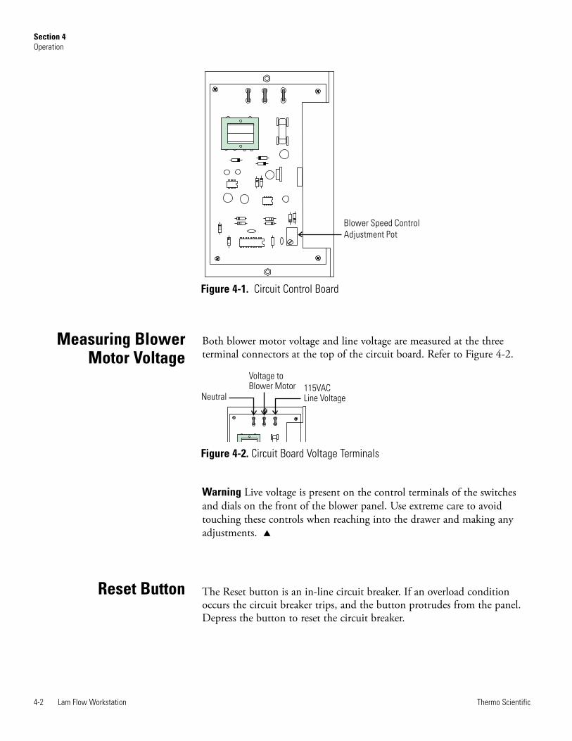
• Blower Speed ControlThe blower speed control, located on the printed circuit control board, isused to adjust the air velocity from the blower motor. Refer to Figure 4-1. A clockwise turn of the screw adjustment (as viewed from the top ofthe control panel) will increase air velocity.
Caution Blower speed was preset at the factory and should only be changedby a qualified technician. s
Control andIndicating Devices
4-2 Lam Flow Workstation Thermo Scientific
Section 4Operation
Measuring BlowerMotor Voltage
Both blower motor voltage and line voltage are measured at the threeterminal connectors at the top of the circuit board. Refer to Figure 4-2.
Warning Live voltage is present on the control terminals of the switchesand dials on the front of the blower panel. Use extreme care to avoidtouching these controls when reaching into the drawer and making anyadjustments. s
The Reset button is an in-line circuit breaker. If an overload conditionoccurs the circuit breaker trips, and the button protrudes from the panel.Depress the button to reset the circuit breaker.
Blower Speed Control
Adjustment Pot
Figure 4-1. Circuit Control Board
Figure 4-2. Circuit Board Voltage Terminals
115VACLine VoltageNeutral
Voltage toBlower Motor
Reset Button

Lam Flow Workstation 5-1Thermo Scientific
Section 5 Certification TestingProcedure
A list of certification companies is included on the Thermo website, or callthe Technical Services department. See Page iv.
Caution Shipping stress can affect the integrity of the cabinet. Certificationby qualified certification personnel only is necessary after installation. s
Certification is recommended:~ On installation,~ Annually,~ If cabinet is moved,~ After HEPA filter(s) replacement,~ After inside cabinet service work.
Due to the stress of shipping and handling and the fragile nature of theHEPA filters, the cabinet must be thoroughly tested when it has beenplaced in its final location. The following tests should be performed forStandard 209B:
• HEPA Filter Leak Test (DOP Test)
• Air Velocity Profile Test
These tests must be performed by qualified service specialists who arefamiliar with the methods and procedures of certifying biological safetycabinets.
The certification should be performed upon installation, annuallythereafter, after filter changes, and after cabinet relocation.
Note Unless this certification was expressly called for in the specification,quotes and/or purchase order, the cost for this on-site testing is to be paidfor by the customer. s
Certification of theCabinet
On-site Certification

5-2 Lam Flow Workstation Thermo Scientific
Section 5Certification Testing Procedure
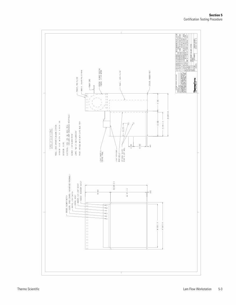
Lam Flow Workstation 5-3Thermo Scientific
Section 5Certification Testing Procedure


Section 6 Routine Maintenance
Recommended routine maintenance information follows.
Note In order to provide an accurate reading, the indicating needle of thestatic pressure gauge should be precisely at zero when the cabinet iscompletely shut off. If the cabinet is connected to a central exhaust system,the exhaust system must also be shut off. s
Following HEPA filter replacement, the static pressure gauge should berechecked for proper zeroing when the cabinet is shut off. When thecabinet is started up and the proper air flow balance has been attained,take a reading on the gauge and record it. This initial reading will serve asa baseline indication of subsequent filter loading. when the readingincreases by approximately 50%, recheck the airflow balance. Filterreplacement will likely be required.
A pre-filter is used in biological safety cabinets to extend the life of theHEPA filters. the pre-filter is located on top of the unit under the airintake grille. The pre-filter should be replaced three times a year,depending upon environmental conditions.
Warning Do not turn the cabinet off. Allow it to run during the pre-filterreplacement procedure. s
Warning De-energize all potential sources of energy to this unit andlockout/tagout their controls. (O.S.H.A. Regulation, Section 1910-147.) s
1. Remove the screws securing the control panel.
2. Slide the control panel out.
3. Grasp the fluorescent light bulb on the right end by the socket andgently push the left socket to release the bulb.
4. Replace with a new bulb.
Lam Flow Workstation 6-1Thermo Scientific
Check Static PressureGauge “Zero”
Replace the Pre-Filter
Replace FluorescentLight Bulb


Section 7 Service
Refer to illustration at the end of this section.
Warning Service to the unit must be performed by qualified personnel.The cabinet should then be recertified. s
Warning Before filters are replaced or any service is performed on thecabinet, decontaminate the unit! s
Warning De-energize all potential sources of energy to this unit andlockout/tagout their controls. (O.S.H.A. Regulation, Section 1910-147.) s
Note Access to the exhaust HEPA filter is through the back of the unit atthe top. Set the unit on the floor if possible. s
1. Remove the plastic pre-filter grille (egg crate) and the pre-filter.
2. Remove the 8 screws securing the blower motor assembly.
3. Remove the tie wrap on the back wall.
4. Remove the blower motor and set it aside.
5. Remove the screws securing the motor blower mounting plate and liftthe entire assembly out of the unit.
6. Carefully remove the wooden “drive” wedges that hold the HEPA filterin place. Lift the filter out of the top of the unit and place it in a heat-sealable polyethylene bag for disposal
7. With a vacuum cleaner, clean all the filter seat surfaces.
8. Slide the new filter in place, check to see that it is properly seated, andthe gasket seal evenly distributed.
9. Set the longer wedge back into the cabinet with the straight sideagainst the back of the filter. Set the shorter drive wedge into positionwith its straight side facing the back of the cabinet. Drive the wedge alittle at a time on each side of the cabinet until the filter is sealed. Theneoprene gasket seal should be compressed at least 50%.
Lam Flow Workstation 7-1Thermo Scientific
Replace the SupplyHEPA Filter

7-2 Lam Flow Workstation Thermo Scientific
Section 7Service
Replace the Blowerand/or Motor
Note Access to the blower is through the pre-filter grille and pre-filter. s
1. Loosen the set bolt on the blower shaft wheel from inside the left sideof the scroll (as viewed from the back).
2. Remove the (3) bolts and washers securing the motor to the scroll onthe right side of the blower assembly.
3. Disconnect the green ground wire.
4. Disconnect the wiring, making note of the wiring configuration.
5. Remove the blower motor and replace it with a new motor. Align theblower wheel and tighten it.
6. Connect the wiring in the same configuration as the old blower motorand reconnect the green ground wire.
7. Replace the pre-filter and pre-filter grille.
Warning After blower motor replacement, recertify the cabinet. s
Ambient Air
Clean Filtered Air
HEPA Filter
Blower
Prefilter Grille
Lights
Protective Grille
Work Surface
Figure 8-1. Side View

Lam Flow Workstation 7-3Thermo Scientific
Section 7Service
Replace the BlowerSpeed Control
1. Remove the screws securing the control panel.
2. Pull out the control panel, and locate the blower speed control on theright side of the control box.
3. Disconnect the wiring to the control, and make note of the wiringconfiguration.
4. Remove the speed control from the inside of the control box.
5. Install the new blower speed control by reversing the above procedure.
Warning After blower speed control replacement, recertify the cabinet. s


Section 8 Troubleshooting
The following is a guide to troubleshooting the safety cabinet system.
Warning Actual servicing of the unit must be performed by specializedservice personnel only. s
Problem: No air flow in the cabinet work area.Possible Causes:
1. Unit is not plugged in. Plug the unit into a proper power source.
2. Blower motor overheated due to low electrical voltage to theblower motor.
3. Step up voltage or increase the speed of the control.
4. Blower motor overheated due to excessive heat load in work area.
5. Blower motor or speed control is defective.
6. If the static pressure gauge reading has increased approximately50% from its initial readings, the filter has likely loaded with dirtand the speed control must be adjusted. If proper airflow cannotbe reached by adjusting the speed control, decontaminate thecabinet and replace all HEPA filters.
7. Defective motor bearings or blower motor.
Problem: Fluorescent light malfunctionPossible Causes:
1. Verify that the lamp is properly installed into the fixture.
Problem: Non-functioning static pressure gaugePossible Causes:
1. Verify that the hose is tightly attached to a high pressure port ofthe gauge and to the cabinet (front top right of the service box). Ifproperly tightened, the static pressure gauge is likely defective andshould be replaced.
Problem: Loud screeching noisePossible Causes:
1. Bad bearings in the motor blower unit.
2. Blower scroll rubbing against housing.
Lam Flow Workstation 8-1Thermo Scientific


Section 9 Specifications
Type . . . . . . . . . . . . . . . . . . . . . . . . . . . .3’ Benchtop Airflow . . . . . . . . . . . . . . . . . . . . . . . . . .(Horizontal) Work Area Dimensions . . . . 34.5”W x 28.4”H x 19.1” F-B
. . . . . . . . . . . .(87.6cm x 72.1cm x 48.5cm)Exterior Dimensions . . . . . 37”W x 49.1”H x 34” F-B
. . . . . . . . . . . . . . .(94.0cm x 124.7cm x 86.4cm)Electrical . . . . . . . . . . . . . . . . . . .115V, 60Hz, 7 FLA Shipping Weight . . . . . . . . . . . . . .290 lbs. (132kg)
The workstation is designed to be electrically safe in the followingenvironmental conditions:• Indoors• Altitude: Up to 2,000 meters• Temperature: 5°C to 43°C• Humidity: 80% RH at or below 31°C, decreasing linearly to
50% RH at 40°C• Mains Supply Fluctuations: ± 10% of nominal. • Installation Category II 1
• Pollution Degree 2 2
• Class of Equipment I
1 Installation category (overvoltage category) defines the level of transient overvoltagewhich the instrument is designed to withstand safely. It depends on the nature of theelectricity supply and its overvoltage protection means. For example, in CAT II which isthe category used for instruments in installations supplied from a supply comparable topublic mains such as hospital and research laboratories and most industrial laboratories,the expected transient overvoltage is 2500V for a 230V supply and 1500V for a 120Vsupply.
2 Pollution degree describes the amount of conductive pollution present in theoperating environment. Pollution degree 2 assumes that normally only non-conductivepollution such as dust occurs with the exception of occasional conductivity caused bycondensation.
Continuing research and improvements may result in specification changes at any time.
Lam Flow Workstation 9-1Thermo Scientific


Lam Flow Workstation 10-1Thermo Scientific
Section 10 Parts List
Stock # . . . . . . . . . . . . . . . . . . . . . . . . .Description 156059 . . . . . . . .Motor, 1/3 HP, 115V, 1075 RPM 900058 . . . . . . . . . . . . . . . . . . . . . . . . . . . . .Blower 170024 . . . . . . . . .Capacitor, Motor, 5MFD, 370V 285812 . . . . . . . .Plug, 15A, 3-wire, Hospital Grade 141021 . . . . . . . .Lamp, Fluorescent, (F40T12/CW)142015 . . . . . . . . . . . . . . . . .F20-T12 Lamp Fixture28003 . . . . . . . . . . .Gasket, 1/8 x 1 Neoprene Tape 460024 . . . . . . . . . . . . . . . . . . .Outlet, 3W Snap-in 73036 . . . . . . . . . . . . . . . . . . . . . . . .Line Cord 16/3760071 . . . . . . . . . . . . . . .Filter, HEPA, 30 x 36 x 6 760075 . . . . . . . . . . . . . .Pre-filter 13.75 x 36.75 x 1


Lam Flow Workstation 11-1Thermo Scientific
Section 11Electrical Schematics

11-2 Lam Flow Workstation Thermo Scientific
Section 11Electrical Schematics

Lam Flow Workstation 12-1Thermo Scientific
Section 12Warranty Information
THER
MO F
ISHE
R SC
IENT
IFIC
LAM
INAR
FLO
W E
QUIP
MENT
WAR
RANT
Y US
AT
he W
arr
anty
Period s
tart
s t
wo w
eeks f
rom
the d
ate
your
equip
ment
is s
hip
ped f
rom
our
facili
ty.
This
allo
ws s
hip
pin
g t
ime
so t
he w
arr
anty
will
go into
effect
at
appro
xim
ate
ly t
he s
am
e t
ime y
our
equip
ment
is d
eliv
ere
d.
The w
arr
anty
pro
tection
exte
nds t
o a
ny s
ubsequent
ow
ner.
During t
he f
irst
thirty
-six
(36)
month
s,
com
ponent
part
s p
roven t
o b
e n
on-c
onfo
rmin
g in m
ate
rial or
work
manship
will
be
repaired o
r re
pla
ced a
t T
herm
o’s
expense,
inclu
din
g labor. I
nsta
llation,
calib
ration a
nd c
ert
ific
ation is n
ot
covere
d b
y t
his
warr
anty
agre
em
ent. T
he T
echnic
al S
erv
ices D
epart
ment
must
be c
onta
cte
d f
or
warr
anty
dete
rmin
ation a
nd d
irection p
rior
to p
erf
orm
ance o
f any r
epairs.
Expendable
ite
ms,
gla
ss,
filters
and g
askets
are
exclu
ded f
rom
this
warr
anty
.
Repla
cem
ent
or
repair o
f com
ponent
part
s o
r equip
ment
under
this
warr
anty
shall
not
exte
nd t
he w
arr
anty
to e
ither
the
equip
ment
or
to t
he c
om
ponent
part
beyond t
he o
rigin
al w
arr
anty
period.
The T
echnic
al S
erv
ices D
epart
ment
must
giv
e
prior
appro
val fo
r re
turn
of
any c
om
ponent
or
equip
ment. A
t T
herm
o’s
option,
all
non-c
onfo
rmin
g p
art
s m
ust
be r
etu
rned t
o
Therm
o p
osta
ge p
aid
and r
epla
cem
ent
part
s a
re s
hip
ped F
OB
destination.
TH
IS W
AR
RA
NT
Y I
S E
XC
LU
SIV
E A
ND
IN
LIE
U O
F A
LL O
TH
ER
WA
RR
AN
TIE
S,
WH
ET
HE
R W
RIT
TE
N,
OR
AL,
OR
IMP
LIE
D.
NO
WA
RR
AN
TIE
S O
F M
ER
CH
AN
TA
BIL
ITY
OR
FIT
NE
SS
FO
R A
PA
RT
ICU
LA
R P
UR
PO
SE
SH
ALL A
PP
LY.
Therm
o s
hall
not
be lia
ble
for
any indirect
or
consequential dam
ages inclu
din
g,
without
limitation,
dam
ages t
o lost
pro
fits
or
loss o
f pro
ducts
.
Your
local T
herm
o S
ale
s O
ffic
e is r
eady t
o h
elp
with c
om
pre
hensiv
e s
ite p
repara
tion info
rmation b
efo
re y
our
equip
ment
arr
ives.
Printe
d instr
uction m
anuals
care
fully
deta
il equip
ment
insta
llation,
opera
tion a
nd p
reventive m
ain
tenance.
If e
quip
ment
serv
ice is r
equired,
ple
ase c
all
your
Technic
al S
erv
ices D
epart
ment
at
1-8
00-4
38-4
851 (
US
A a
nd C
anada)
or
1-7
40-3
73-4
763.
We’re r
eady t
o a
nsw
er
your
questions o
n e
quip
ment
warr
anty
, opera
tion,
main
tenance,
serv
ice,
and s
pe-
cia
l applic
ations.
Outs
ide t
he U
SA
, contr
act
your
local dis
trib
uto
r fo
r w
arr
anty
info
rmation.
ISO
9001
REGI
STER
EDR
ev.
5
4/0
9
12-2 Lam Flow Workstation Thermo Scientific
Section 12Warranty Information
THER
MO F
ISHE
R SC
IENT
IFIC
LAM
INAR
FLO
W E
QUIP
MENT
WAR
RANT
Y IN
TERN
ATIO
NAL
Th
e W
arr
an
ty P
erio
d s
tart
s t
wo
mo
nth
s f
rom
th
e d
ate
yo
ur
eq
uip
me
nt
is s
hip
pe
d f
rom
ou
r fa
cili
ty.
Th
is a
llow
s s
hip
pin
g
tim
e s
o t
he
wa
rra
nty
will
go
in
to e
ffe
ct
at
ap
pro
xim
ate
ly t
he
sa
me
tim
e y
ou
r e
qu
ipm
en
t is
de
live
red
. T
he
wa
rra
nty
pro
tec-
tio
n e
xte
nd
s t
o a
ny s
ub
se
qu
en
t o
wn
er.
Du
rin
g t
he
first
thirty
six
(3
6)
mo
nth
s,
co
mp
on
en
t pa
rts p
rove
n t
o b
e n
on
-co
nfo
rmin
g in
ma
teria
l o
r w
ork
ma
nsh
ip w
ill b
e
repa
ire
d o
r re
pla
ce
d a
t T
he
rmo
’s e
xp
en
se
, e
xce
ptin
g la
bo
r. I
nsta
llatio
n,
ca
libra
tio
n a
nd
ce
rtific
atio
n is n
ot
co
ve
red
by t
his
wa
rra
nty
ag
ree
me
nt.
Th
e T
ech
nic
al S
erv
ice
s D
epa
rtm
en
t m
ust
be
co
nta
cte
d f
or
wa
rra
nty
de
term
ina
tio
n a
nd
dire
ctio
n
prio
r to
pe
rfo
rma
nce
of
an
y r
epa
irs.
Exp
en
da
ble
ite
ms,
gla
ss,
filte
rs a
nd
ga
ske
ts a
re e
xclu
de
d f
rom
th
is w
arr
an
ty.
Re
pla
ce
me
nt
or
repa
ir o
f co
mp
on
en
t pa
rts o
r e
qu
ipm
en
t u
nd
er
this
wa
rra
nty
sh
all
no
t e
xte
nd
th
e w
arr
an
ty t
o e
ith
er
the
eq
uip
me
nt
or
to t
he
co
mp
on
en
t pa
rt b
eyo
nd
th
e o
rig
ina
l w
arr
an
ty p
erio
d.
Th
e T
ech
nic
al S
erv
ice
s D
epa
rtm
en
t m
ust
giv
e
prio
r a
pp
rova
l fo
r re
turn
of
an
y c
om
po
ne
nt
or
eq
uip
me
nt.
At
Th
erm
o’s
op
tio
n,
all
no
n-c
on
form
ing
pa
rts m
ust
be
re
turn
ed
to T
he
rmo
po
sta
ge
pa
id a
nd
re
pla
ce
me
nt
pa
rts a
re s
hip
pe
d F
OB
de
stin
atio
n.
TH
IS W
AR
RA
NT
Y I
S E
XC
LU
SIV
E A
ND
IN
LIE
U O
F A
LL O
TH
ER
WA
RR
AN
TIE
S,
WH
ET
HE
R W
RIT
TE
N,
OR
AL
, O
R
IMP
LIE
D.
NO
WA
RR
AN
TIE
S O
F M
ER
CH
AN
TA
BIL
ITY
OR
FIT
NE
SS
FO
R A
PA
RT
ICU
LA
R P
UR
PO
SE
SH
AL
L A
PP
LY.
Th
erm
o s
ha
ll n
ot
be
lia
ble
fo
r a
ny in
dire
ct
or
co
nse
qu
en
tia
l d
am
ag
es in
clu
din
g,
with
ou
t lim
ita
tio
n,
da
ma
ge
s t
o lo
st
pro
fits
or
loss o
f p
rod
ucts
.
Yo
ur
loca
l T
he
rmo
Sa
les O
ffic
e is r
ea
dy t
o h
elp
with
co
mp
reh
en
siv
e s
ite
pre
pa
ratio
n in
form
atio
n b
efo
re y
ou
r e
qu
ipm
en
t
arr
ive
s.
Prin
ted
in
str
uctio
n m
an
ua
ls c
are
fully
de
tail
eq
uip
me
nt
insta
llatio
n,
op
era
tio
n a
nd
pre
ve
ntive
ma
inte
na
nce
.
If e
qu
ipm
en
t se
rvic
e is r
eq
uire
d,
ple
ase
ca
ll yo
ur
Te
ch
nic
al S
erv
ice
s D
epa
rtm
en
t a
t 1
-80
0-4
38
-48
51
(U
SA
or
Ca
na
da
) o
r
1-7
40
-37
3-4
76
3.
We
’re
re
ad
y t
o a
nsw
er
yo
ur
qu
estio
ns o
n e
qu
ipm
en
t w
arr
an
ty,
op
era
tio
n,
ma
inte
na
nce
, se
rvic
e,
an
d
sp
ecia
l a
pp
lica
tio
ns.
Ou
tsid
e t
he
US
A,
co
ntr
act
yo
ur
loca
l d
istr
ibu
tor
for
wa
rra
nty
in
form
atio
n.
ISO
9001
REGI
STER
EDR
ev.
5
4/0
9

Lam Flow Workstation 13-1Thermo Scientific
Section 13Appendix
Locating a Certification Company Biological safety cabinet certification consists of a series of tests designed to verify that the cabinet is performing within operating parameters established by the manufacturer. To assure that a biological safety cabinet is operating as intended, each cabinet should be field-tested at the time of installation and at least annually thereafter. Cabinets should be re-certified whenever HEPA filters are changed, internal maintenance is performed, or is relocated. Three industry-related organizations maintain lists of companies and individuals who are active in the certification industry. You may contact these organizations at the addresses listed below. NSF International (NSF) and International Air Filtration Certifiers Association (IAFCA) sponsor certifier accreditation programs. Accredited certifiers have demonstrated proficiency at testing biological safety cabinets by successfully completing written and/or practical examinations. Biohazard Cabinet Field Certifier Program NSF International PO Box 130140 789 N. Dixboro Rd Ann Arbor, MI 48113-0140 Telephone (734) 769-8010 Or (800) NSF-MARK Fax (734) 769-0109 http://www.nsf.org/Certified/Biohazard-Certifier
IAFCA PO Box 12155 Columbus, OH 43212 Telephone (888) 679-1904 Fax (614) 486-1108 http://www.iafca.com/certifier.html
The Controlled Environment Testing Association (CETA) is a trade association devoted to promoting and developing quality assurance within the controlled environment testing industry. A list of active members is available by contacting the organization. Controlled Environment Testing Association 1500 Sunday Drive Suite 102 Raleigh, NC 27607 Telephone (919) 787-5181 Fax (919) 787-4916 http://www.cetainternational.org/members/corp_indiv.htm For your convenience we have included a partial list of agencies that perform certification on our website. If you do not find someone listed in your area, please contact Thermo’s Technical Services department for additional references.


Thermo Fisher Scientific401 Millcreek RoadMarietta, Ohio 45750United States
www.thermofisher.com