Embed Size (px)
Citation preview

MODEL 224/224CDIFFERENTIAL PRESSURE UNIT (DPU)
(M224C for Industrial Service andBarton® brand M224 (non-C) for
Nuclear Service)
Installation Manual(Replaces/Supersedes ID#10085)
Part No. 10087, Rev. 01July 2007
CONTENTSPrepages................................................................................ . Page.2Section.1.-.Introduction
1-1..General.................................................................... . Page.31-2..Product.Description................................................... . Page.31-3. Specifications............................................................ . Page.3
Table 1-1. DPU Material/Range Specifications............. . Page.41-4..Theory.of.Operation.................................................. . Page.5
Section.2.-.Installation2-1..General.................................................................... . Page.72-2..DPU.Mounting.......................................................... . Page.72-3..DPU.Piping............................................................... . Page.72-4..DPU.Piping/Startup.Examples................................... . Page.9
Section.3.-.Maintenance.and.Calibration3-1..Required.Tools.......................................................... . Page.193-2..Test/Calibration.Equipment........................................ . Page.193-3..Preventative.Maintenance........................................... . Page.193-4..Calibration................................................................ . Page.193-5..DPU.Cleaning/Inspection........................................... . Page.19
A..Pressure.Check..................................................... . Page.20B..Cleaning.and.Inspection.Procedure.......................... . Page.20
Table.3-1..Bolt.Torque.Ratings............................... . Page.21/223-6..Servicing................................................................... . Page.233-7..Attaching.Drive.Arm.to.Torque.Tube........................... . Page.243-8..Drive.Arm.Tightness.Test........................................... . Page.24
Section.4.-.TroubleshootingTable.4-1..Troubleshooting................................................ . Page.25
Section.5.-.Dimensions............................................................ . Page.26/27Section.6.-.Parts.Drawing/List................................................. . Page.28
[This manual is for DPU only - see separate instrument manual.]

�
PRODUCT WARRANTY STATEMENTProduct.warranty.for.this.instrument.is.as.stated.on.the.back.cover.of.this.manual..NOTICE:.DPU.warranty.will.be.voided.if.the.following.limitations.are.exceeded:
Temperature.-.Do.not.subject.the.DPU.to.temperatures.above.200°F.or.below.-60°F.(+40°F minimum for water filled units).Pressure.-.Do.not.subject.the.DPU.to.operating.pressures.in.excess.of.the.working.pressure.rating.stamped.on.the.unit.or.attached.dataplate.Corrosion.-.Do.not.subject.the.DPU.to.incompatible.process.media.Sealed.Components.-.Do.not.loosen.or.remove.the.torque.tube.gland.nut,.the.drive.arm.hole.plug,.or.the.torque.tube.housing.from.the.centerplate..To.do.so.will.cause.loss.of.bellows fill fluid and render the unit inoperable.Vibration/Shock.-.Do.not.subject.the.DPU.to.severe.mechanical.or.hydraulic.shock.
RECORD OF CHANGES
VERSION DATE DESCRIPTION (initial issue 95E1 [5/95])
99D8 8/99 Updated.specs.,.Table.4-1,.Table.5-1,.and.Section.6.drawings
01D18d 4/01 Revised.to.Booklet.Format
03G50c 7/03 Rev..Co..Name/Logo;.Rev..Sections.1,.2,.&.3.for.PED.compliance
03H50b(ID#10087)
8/03 Rev. Spec. Table 1-1; Combined 224 and 224C (replaces 10080); Add 224.DPU.information.to.Section.6
04C50b(ID#10085)
8/03 Produced.separate.manual.under.Barton.brand.for.Nuclear/Government.Service (No Tech. Changes from ID#10085)
06C75m(ID#10087)
4/06 Eliminated separate Barton-brand manual (ID#10085); Rev. Safety/ "C" Ver..statements;.Rev..Tables.1-1,.3-1,.and.6-1;.Added.Piping/Startup.Examples (para. 2-4); Rev. housing bolt caution to warning (page 8); Rev. Figure.6-1;.non-technical.changes.throughout
06D76a 4/06 Removed.Government.Service.designation;.No.Tech..Changes.
01 7/07 Revised corporate name/logo/contact information to reflect Cameron ownership.
SAFETYBefore.installing.this.instrument,.become.familiar.with.the.installation.instructions.in.Section.2.and.in.the.separate.instrument.manual..
DANGER.notes.indicate.the.presence.of.a.hazard.which.will.cause.severe.personal.injury,.death,.or.substantial.property.damage.if.warning.is.ignored.
WARNING.notes.indicate.the.presence.of.a.hazard.which.can.cause.severe.personal.injury,.death,.or.substantial.property.damage.if.warning.is.ignored.
CAUTION.notes.indicate.the.presence.of.a.hazard.which.will.or.can.cause.moderate.personal.injury.or.property.damage.if.warning.is.ignored.
DANGER,.WARNING,.and/or.CAUTION.notes.that.appear.on.the.following.pages.of.this.manual.should.be.reviewed.before.proceeding:.3,.7,.8,.19,.20,.and.23..(Important!.Before.installing.or.operating.this.instrument,.review.all.safety.notices.contained.in.the.separate actuated instrument manual.)
"C" VERSION DESIGN CHANGEThe 224C is a redesigned version of the 224 DPU. The "C" version is identical in func-tion,.performance,.installation,.and.operation.to.the.previous.version..-.redesign.was.for.improved.manufacturing.only..This.design.change.does.not.affect.the.instrument.being.actuated. Barton-brand Model 224 (Non-C) DPU configurations are for Nuclear service only..

�
SECTION 1 - INTRODUCTION
1-1. GeneralThe Model 224/224C Differential Pressure Unit (DPU) is a mechanical device that measures differential pressure relative to a gas or liquid flowing through a process.system,.or.to.the.level.of.a.liquid.contained.in.a.process.vessel.For process flow measurements, the DPU is connected across a primary device (e.g., venturi, orifice plate, or flow tube) located in the process system.For.liquid.level.measurements,.the.DPU.may.be.connected.in.a.variety.of.ways.to.measure.the.difference.in.pressure.caused.by.variations.in.the.level.of.the.liquid.in.the.process.vessel.
1-2. Product DescriptionThe.Model.224/224C.DPU.is.a.dual.bellows.assembly.enclosed.within.pressure.housings..The.dual.bellows.assembly.consists.of.two.opposing.internally.con-nected liquid-filled bellows, a center-block, range springs, overrange valves, and a.torque.tube.assembly.The.pressure.housings.are.connected.by.pipe.or.tubing.to.the.primary.device.located.in.the.system.piping..Variations.in.differential.pressure.within.the.pressure.housings.cause.the.bellows.to.expand.or.contract.in.a.linear.direction.towards.the.side.having.the.lowest.pressure.The.linear.movement.of.the.bellows.is.converted.into.angular.rotation.when.transmitted.to.the.torque.tube.shaft.by.the.drive.arm.and.this.mechanical.motion.actuates.the.mechanism.of.the.process.monitoring.instrument.The.process.monitoring.instrument.that.is.connected.to.the.torque.tube.assem-bly.may.be.an.indicator,.a.switch,.a.transmitter,.a.recorder,.or.other.process.control.device.
1-3. SpecificationsThe.Model.224/224C.DPU.is.available.in.various.pressure.ratings.to.measure.to specific ranges between 0-30 inches of water column and 0-1000 psi, with safe working pressure (SWP) ratings from 500 to 10,000 psi (224 Non-C lim-ited to 500 to 3,000 psi SWP). See Table 1-1, page 4.The 224C Bellows Unit Assembly (BUA) is produced in three bellows sizes: 1-5/8.inch,.5/8.inch,.and.3/4.inch.diameter.The.1-5/8.inch.diameter.BUA.accommodates.differential.pressures.to.55.psi..The.range.springs.of.this.BUA.are.contained.within.the.bellows.and.do.not.come.in.contact.with.the.measured.liquid.The.3/4.inch.BUA.accommodates.differential.pressures.up.to.400.psi.and.the.5/8.inch.BUA.up.to.1,000.psi..The.range.springs.of.these.BUAs.are.grouped.around.the.outside.of.the.bellows.and.must.be.of.a.material.that.is.compatible.with.the.liquid.being.measured.
CAUTIONAmbient.temperatures.below.+40°F.should.never.be.allowed.for.water.filled (D-fill) units.

�
224/224C DPU Specifications
Tabl
e 1-
1. 2
24/2
24C
DP
U M
ater
ial/
Ran
ge S
peci
ficat
ions
(4/0
6a)
BO
DY
AVA
ILA
BLE
DIF
FER
ENTI
AL
PRES
SUR
E R
AN
GES
PRES
SUR
E C
ON
NEC
TIO
NS
SWP
psi (
bar)
Hou
sing
Mat
eria
lSt
ainl
ess
Stee
l or
Inco
nel B
ello
ws
Ber
ylliu
m C
oppe
r Bel
low
s (�
��C
Onl
y)In
cone
l Bel
low
sTo
pB
otto
m1-
5/8"
(�1m
m) O
.D.
1-5/
8" (�
1mm
) O.D
.�/
�" (1
9mm
) O.D
.�/
�" (1
9mm
) O.D
.5/
8" (1
6mm
) O.D
.
���C
500
(34)
Forg
ed B
rass
(A
STM
-B12
4#2)
0-30
" w.c
. (0-
75 m
bar)
to
0-60
psi
(0-4
.1 b
ar)
0-61
psi
(0-4
.2 b
ar) t
o 0-
400
psi (
0-27
.6 b
ar)
0-40
0 ps
i (0-
27.6
bar
) to
0-50
0 ps
i (0-
34 b
ar)
1/4"
NP
T1/
4" N
PT
��� (Non-C)*
500
(34)
Col
d R
olle
d S
teel
(C10
18)
Sta
inle
ss S
teel
(316
)0-
30" w
.c. (
0-75
mba
r) to
0-
60 p
si (0
-4.1
bar
)
0-61
psi
(0-4
.2 b
ar) t
o 0-
400
psi (
0-27
.6 b
ar)
0-40
0 ps
i (0-
27.6
bar
) to
0-50
0 ps
i (0-
34 b
ar)
1/4"
NP
T1/
4" N
PT
1,00
0 (6
9)C
oppe
r Nic
kel (
70-3
0)
(MIL
-C-1
5726
)
0-60
" w.c
. (0-
149
mba
r) to
0-
60 p
si (0
-4.1
bar
)0-
61 p
si (0
-4.2
bar
) to
0-40
0 ps
i (0-
27.6
bar
)0-
400
psi (
0-27
.6 b
ar) t
o 0-
1000
psi
(0-6
9 ba
r)
MS
-161
42-4
MS
-161
42-4
1,50
0 (1
03)
Col
d R
olle
d S
teel
(C10
18)
Sta
inle
ss S
teel
(316
)
0-60
" w.c
. (0-
149
mba
r) to
0-
60 p
si (0
-4.1
bar
)0-
61 p
si (0
-4.2
bar
) to
0-40
0 ps
i (0-
27.6
bar
)
1/4"
NP
T1/
4" N
PT
3,00
0 (2
07)
Col
d R
olle
d S
teel
(C10
18)
Sta
inle
ss S
teel
(316
) M
onel
1/2"
NP
T1/
4" N
PT
6,00
0 (4
14)
Col
d R
olle
d S
teel
(C10
18)
Sta
inle
ss S
teel
(316
)1/
2" N
PT
1/4"
NP
T
10,0
00
(689
)
Allo
y S
teel
(414
0)0-
100"
w.c
. (0-
248
mba
r) to
0-
60 p
si (0
-4.1
bar
)0-
100"
w.c
. (0-
248
mba
r) to
0-
60 p
si (0
-4.1
bar
)1/
4" N
PT
9/16
AM
INC
O
(1/4
" OD
T)
1/4"
NP
T 9/
16 A
MIN
CO
(1
/4" O
DT)
Net
Vol
ume
cu.in
. (cu
. cm
)L.
P. H
ead
1.66
" (27
.2 c
c)1.
66" (
27.2
cc)
2.51
" (41
.1 c
c)2.
51" (
41.1
cc)
2.61
" (42
.8 c
c)
H.P
. Hea
d1.
55" (
25.4
cc)
1.55
" (25
.4 c
c)2.
42" (
39.7
cc)
2.42
" (39
.7 c
c)2.
50" (
40.9
cc)
Dis
plac
emen
t cu.
in. (
cu. c
m) f
or fu
ll-sc
ale
Trav
el0.
14" (
2.3
cc)
0.14
" (2.
3 cc
)0.
03" (
0.49
cc)
0.03
" (0.
49 c
c)0.
025"
(0.4
1 cc
)
Perf
orm
ance
: Tor
que
Tube
Rot
atio
n =
8° ±
10%
; Tor
que
Tube
Mat
eria
l = B
eryl
lium
Cop
per (
BeC
u); T
empe
ratu
re L
imits
= -4
0°F/
°C to
+18
0°F
(+82
°C);
Max
imum
Non
-line
arity
= p
er R
ange
; R
epea
tabi
lity
= 0.
2% o
f ful
l sca
le d
iffer
entia
l pre
ssur
e (s
ee D
P In
dica
tors
, Sw
itche
s, &
Tra
nsm
itter
s bu
lletin
#21
920
for a
dditi
onal
info
rmat
ion)
.
Not
es: Z
ero
cent
er o
r spl
it ra
nges
ava
ilabl
e on
spe
cial
ord
er (e
.g.,
0-60
" w.c
. (0-
149
mba
r) ra
nge
may
be
orde
red
30-0
-30"
w.c
. (75
-0-7
5 m
bar)
or (
15-0
-45"
w.c
. (37
-0-1
12 m
bar)
. Abs
olut
e pr
essu
re ra
nges
ava
ilabl
e fro
m 3
0" w
.c. (
75
mba
r) to
600
psi
(41.
4 m
bar)
. Oth
er s
izes
and
type
s of
con
nect
ions
(wel
ding
stu
bs, M
A, A
.N.D
., et
c.) a
vaila
ble
upon
requ
est.
Out
line
dim
ensi
on d
raw
ings
ava
ilabl
e up
on re
ques
t. M
etric
con
vers
ions
( ) a
re a
ppro
xim
ate.
M22
4C w
ith
NA
CE
(MR
-01-
75) c
ompl
iant
mat
eria
ls a
vaila
ble
upon
requ
est.
*Mod
el �
�� (N
on-C
) for
spe
cific
Nuc
lear
ser
vice
app
licat
ions
onl
y.

5
Torque Tube
Range Spring
Center Plate
Low PressureHigh Pressure
TemperatureCompensator
LP Connection
Low Pressure
High Pressure
Range Spring
HP Connection
1-4. Theory of OperationThe M224/224C DPU measures the differential pressure (DP) in a process system.relative.to.process.functions.and.produces.a.mechanical.output.that.actu-ates.process.monitoring.instruments.and.process.control.devices.
The high-pressure (HP) housing is connected by pipe or tubing to the high-pres-sure side of the primary device. The low-pressure (LP) housing is connected to the.low-pressure.side.of.the.primary.device.Any.pressure.changes.within.the.housings.causes.the.bellows.to.move.in.the.direction.of.least.pressure..As.the.bellows.move.laterally,.the.connecting.drive.arm.follows.the.motion.of.the.bellows,.and.twists.the.torque.tube.The.torque.tube.shaft,.which.is.freely.supported.within.the.torque.tube.at.its.outer.end,.but.attached.to.the.torque.tube.and.drive.arm.at.the.inner.end,.rotates.through.the.same.angle.as.the.drive.arm..The.rotation.of.the.torque.tube.shaft.provides.the.mechanical.motion.required.to.actuate.process.instruments,.such.as.recorders,.indicators,.transmitters,.controllers,.and.switches.If.the.bellows.are.subjected.to.a.pressure.greater.than.the.range.of.the.DPU,.they.move.their.normal.travel.range.and.a.small.amount.of.overtravel.until.the.overrange valve seals against the valve seat. As the valve closes, the fill liquid is trapped in the bellows. Since the fill fluid is essentially noncompressible, the bel-lows.are.fully.supported.and.will.not.be.damaged.regardless.of.the.overpressure.(up to the full rated pressure of the instrument) applied to them. Also, since dual overrange.valves.are.used,.full.protection.against.overrange.is.provided.in.either.direction.An.additional.convolution.in.the.high-pressure.side.of.the.bellows.provides.for expansion or contraction of the fill fluid relative to ambient temperature changes. This extra convolution acts as an accumulator permitting the fill fluid to.change.volume.without.materially.affecting.the.pressure.within.the.bellows.or.changing.the.physical.relationship.of.the.two.bellows.
Figure.1-1..DPU.Components

6
(Blank Page)

�
SECTION 2 - INSTALLATION
2-1. GeneralThe.instrument.should.be.inspected.at.time.of.unpacking.to.detect.any.damage.that.may.have.occurred.during.shipment..Note: The DPU was checked for accuracy at the factory — do not change any of the settings during examina-tion or accuracy will be affected.
For applications requiring special cleaning/precautions, a polyethylene bag is used to protect the instrument from contamination. This bag should be removed only under conditions of extreme cleanliness.
2-2. DPU MountingA.. Flush.or.Panel
1. Cut an opening in the panel and drill four holes (17/64"), per outline dimension.drawings.in.Section.5.
2. Pass the instrument through the cutout in the panel (from panel front).3.. Attach.the.indicator.to.the.panel.with.four.screws.
C.. Pipe. Refer.to.Section.5..The.unit.must.be.mounted.approximately.level.for.
proper.operation.
2-3. DPU Piping
WARNINGHIGH.PRESSURE.HAZARD..TO.PREVENT.PERSONAL.INJURY.OR. DAMAGE. TO. EQUIPMENT,. DIRECT. ALL. PIPING. AWAY.FROM. THE. OPERATOR. WHILE. CONNECTING. THE. DPU. TO.THE.SYSTEM.PIPING.
WARNINGEXPLOSION. HAZARD.. NO. ORGANIC. COMPOUNDS,. OIL,.GREASE,.DIRT,.OR.SCALE.OF.ANY.KIND.CAN.BE.TOLERATED.IN.AN.OXYGEN.INSTALLATION.
WARNINGFOR.INSTALLATIONS.WHERE.THE.PRESSURE.COULD.EXCEED.THE.RATED.MAXIMUM.SAFE.WORKING.PRESSURE.OF.THE.DPU,. THE. PIPING. SYSTEM. MUST. INCLUDE. PROTECTIVE.MEASURES.TO.PREVENT.OVER.PRESSURE,.IN.ACCORDANCE.WITH.APPLICABLE.LOCAL.AND.NATIONAL.PIPING.CODES.
WARNINGTHE. MODEL. 224/224C. DPU. IS. NOT. DESIGNED. FOR. HIGH.STATIC.OR.DYNAMIC.LOADS.AT.IMPULSE.LINE.CONNECTIONS..THE. IMPULSE. PIPING. SYSTEM. MUST. BE. DESIGNED. WITH.ADEQUATE. SUPPORTS. TO. MINIMIZE. THE. LOADS. AT. THE.DPU.

8
2-3. DPU Piping (Cont.)
WARNINGDO. NOT. REUSE. HOUSING. BOLTS.. SEE. HOUSING. BOLT.WARNING.ON.PAGE.20.
CAUTIONDPU.pressure.rating.has.been.determined.using.standard.methods.without specific considerations for corrosion (internal or external) or fatigue..The.system.designer.should.appropriately.derate.any.DPU.where these considerations are significant issues. Do not subject DPU to.unnecessary.shock/overrange.pressure.during.operation.
CAUTIONDPU bellows protects torque tube from exposure to process fluid. Cyclic. conditions. can. cause.undetected.bellows. failure. resulting. in.exposure of the torque tube to the process fluid.
NOTICEDo not share filling or vapor return lines with DPU piping lines.
Standard Piping Practices (observe when installing piping):1.. Shorten.distance.between.primary.device.and.DPU.as.much.as.possible...
Distances.exceeding.100.feet.are.not.recommended...For.distances.up.to.50.feet,.use.1/4-inch.pipe.or.tubing...For.runs.50.to.100.feet,.use.1/2-inch.pipe.or.tubing...The.recommended.limitation.does.not.apply.if.an.air.purge.or.blow-back.system.is.used.
2.. Slope.all.piping.at.least.1-inch/linear.foot.to.avoid.liquid/gas.entrapment.3.. Provide.two.feet.of.un-insulated.piping.between.the.DPU.and.the.primary.
device for each 100 degrees in excess of +180°F (+162°C), if process media exceeding +200°F (+93.3°C) must be measured.
4 Assure that the temperature of the DPU never exceeds 180°F (+162°C). When steam tracing is necessary, the steam pressure should not exceed five pounds.per.square.inch.and.insulation.should.not.be.used...If.pressure.must.exceed five pounds per square inch, limit the length of tubing around the DPU.to.two.turns.and.do.not.insulate.
5.. When.severe.pulsation.is.present,.install.a.suitable.pulsation.dampening.device.upstream.of.the.DPU;.otherwise,.accuracy.will.be.affected.
6.. Mount.DPU.on.a.solid.support.to.minimize.vibration...Tighten.all.points,.using.a.suitable.compound;.leaks.in.piping.can.cause.measurement.errors.
7.. Rotate.the.housing.as.necessary.to.place.the.connection.in.the.proper.posi-tion...The.DPU.has.connections.in.the.pressure.housings.to.accommodate.various pipe sizes (refer to Section 5).
8.. Install.a.valve.manifold.connecting.the.DPU.and.the.source.of.differential.pressure.to.facilitate.operation.and.checking.of.the.DPU.
9.. Install.all.shutoff.and.bypass.valves.so.they.are.easily.accessible.from.front.of.instrument...Locate.block.valves.at.the.source.of.differential.pressure.
10.. For.gas.service,.it.is.recommended.that.zero.check.be.performed.with.both.block valves closed. If gas flow is pulsating, a standing wave effect may be in the process line displacing the indicator (appearing to be a zero error).

9
2-4. DPU Piping/Startup Examples"Typical" piping diagrams and startup procedures are presented on pages 9-17. For specific application/installation/piping information, contact Cameron. Review all WARNINGS, CAUTIONS, AND NOTICES (pages 7 and 8) before installation.or.startup.• Flow Applications (pages 9-13) (HP = High Pressure). Ensure.DPU.HP.housing.is.connected.to.the.primary.device.upstream.tap.. NOTICE:..To.prevent.overheating.DPU.during.blow-down,.operator.should.
monitor.temperature.by.placing.his.hands.on.pipe.between.DPU.and.the..manifold.pipe.containing.the.vent.valves.
• Liquid Level Applications (pages 13-16) The process media may be used as a reference leg seal fluid when it is of
a.type.that.will.condense.in.the.reference.leg.under.all.conditions..If.the.process.or.process.media.characteristics.are.such.that.the.above.conditions.cannot be met, a special reference leg seal fluid will be required.
If special seal fluid media characteristics are such that the above conditions cannot be met, a special reference leg seal fluid will be required. The spe-cial seal fluid must not be volatile and must not be miscible with the process media. The difference in densities (special seal fluid vs process media) will require.compensation.in.calculating.differential.pressure.range.of.the.DPU.
• Liquid Specific Gravity Applications (page 17) This method of piping is used for determining specific gravity changes in a
process.media.using.differential.pressure.instruments.A.. Gas.Flow,.DPU.Above.Run. Recommended.for.use.whenever.possible,.as.the.DPU.is.self-draining..
However,.NOT.recommended.when.hydrates.are.present.1. Open bypass valve(s) and close vent valve.2.. Open.both.shutoff.valves.
and.one.block.valve.to.pressurize.DPU,.then.close.block.valve.
3.. Close.one.bypass.valve.and.check..system.for.leaks..If.output.travels.upscale,.check.for.low-pressure.piping.leaks..If.output.travels.downscale,.check.for.high-pressure.piping.leaks.
4.. Repair.piping.if.necessary.and.repeat.steps.1.through.3.until.output.remains.stationary.at.zero.
5. Close both shutoff valves and open bypass valve(s).6.. Open.both.block.valves.and.slowly.open.both.shutoff.valves.7.. Close.bypass.valves.and.if.two.bypass.valves.are.used,.open.vent.valve.8.. Close.bypass.valves,.and.if.two.bypass.valves.are.used,.open.vent.
valve.
Figure.2-1..Gas.Flow,.DPU.Above.Run

10
B.. Gas.Flow,.DPU.Below.Run. Used.only.when.necessary.to.mount.the.DPU.below.run..Drip.pots.are.
required.when.wet.gas.is.present.1. Open bypass valve(s) and
close.vent.valve.2.. Open.both.shutoff.valves.
and.one.block.valve.to.pressurize.DPU,.then.close.block.valve.
3.. Close.one.bypass.valve.and.check.system.for.leaks..If.output.travels.upscale,.check.for.low-pressure.piping.leaks..If.output.travels.downscale,.check.for.high-pressure.piping.leaks.
4.. Repair.piping.if.necessary.and.repeat.steps.1.through.3.until.output.remains.stationary.at.zero.
5. Close both shutoff valves and open bypass valve(s).6.. Open.both.block.valves.and.slowly.open.both.shutoff.valves.7.. Close.bypass.valves,.and.if.two.bypass.valves.are.used,.open.vent.
valve.8.. If.drip.pots.are.used,.open.drip.valves.and.blow.out.accumulated.liquid.
C.. Gas.Flow,.Hydrates.Present. The.following.is.used.if.hydrates.or.heavy.solids.are.present,.piping.and.
shutoff.not.less.than.1/2-inch.in.diameter..Bypass.the.manifold.above.to.isolate.the.meter.from.con-necting.piping..Drip.pots.prevent.plugging.1. Open bypass valve(s) and
close.vent.valve.2.. Open.both.shutoff.valves.
and.one.block.valve.to.pressurize.the.DPU,.then.close.block.valve.
3.. Close.one.bypass.valve.and.check.system.for.leaks..If.output.trav-els.upscale,.check.for.low-pressure.piping.leaks..If.output.travels.downscale,.check.for.high-pressure.piping.leaks.
4.. Repair.piping.if.necessary.and.repeat.steps.1.through.3.until.output.remains.stationary.at.zero.
5.. Close.bypass.valves..If.two.bypass.valves.are.used,.open.vent.valve.
2-4. DPU Piping/Startup Examples (Continued)Review all WARNINGS, CAUTIONS, AND NOTICES (pages 7 and 8) before installation.or.startup.
Figure.2-2..Gas.Flow,.DPU.Below.Run
Figure.2-3..Gas.Flow,.Hydrates.Present

11
6.. Drain.drip.pots.of.hydrates.at.regular.intervals.D.. Steam.Flow,.DPU.Below.Run For this application, condensing reservoirs and piping to orifice taps must
be.level..Assure.that.the.reservoir.and.steam.lines.are.at.the.same.level..Two-inch.pipe.crosses.may.be.used.as.seal.pots.1.. Close.vent.valves.if.used,.open.
bypass.and.shutoff.valves.2.. Remove.condensing.reservoir.side.
and fill plugs.3.. Pour.water.into.both.reservoirs.
until.piping.and.DPU.housings.are filled. Piping and housing chambers.shall.be.free.of.bubbles..The.pointer.will.rest.at.zero.(or.output.will.be.4.mA.or.10.mA.as.applicable) when the instrument and piping are completely filled.
4. Install side and fill plugs in reservoirs.5.. Close.shutoff.valves.and.open.block.valves.6.. Slowly.open.both.shutoff.valves.simultaneously.and.check.for.leaks.7.. Close.bypass.valve.
. NOTICE:..Ensure.that.plugs.are.used.and.never.valves.on.the.DPU.E.. Liquid.Flow,.DPU.Above.Run. The.following.steps.should.be.used.if.sediments.may.be.present..Inspect.
piping.periodically..Not.recom-mended.for.hot.or.gassy.liquids.1.. Close.both.shutoff.valves.and.
open.both.block.valves.2.. Open.bypass.valve..Crack.
vent.valves.or.loosen.plugs.from.top.ports.of.DPU.body.housings.
3.. Crack.and.close.shutoff.valves.alternately.until.liquid.is.free.of.bubbles.and.spills.out.of.both.upper.DPU.body.ports.
4.. Close.vent.valves.or.tighten.plugs..Close.block.valves.and.open.shutoff.valves.
5.. The.pointer.will.rest.at.zero.(or.output.will.be.4.mA.or.10.mA.as.appli-cable). If not and no leaks are detected, the housing and/or piping are not completely filled with liquid. Repeat steps 1 through 4 until output remains.stationary.at.the.lowest.value.
2-4. DPU Piping/Startup Examples (Continued)Review all WARNINGS, CAUTIONS, AND NOTICES (pages 7 and 8) before installation.or.startup.
Figure.2-5..Steam.Flow,.DPU.Above.Run

1�
6.. Slowly.open.both.block.valves.and.close.bypass.valve.F.. Liquid.Flow,.DPU.Below.Run. The.following.steps.are.recommended.for.hot.or.gassy.liquids..Periodic.
inspections.of.piping.are.recommended.1.. Close.both.shutoff.valves.
and.open.both.block.valves.
2.. Open.bypass.valve..Crack.vent.valves.or.loosen.plugs.from.top.ports.of.DPU.pressure.housings.
3.. Crack.and.close.shutoff.valves.alternately.until.the.liquid.is.free.of.bubbles.and.spills.out.of.both.upper.DPU.body.ports.
4.. Close.vent.valves.or.tighten.plugs..Close.block.valves.and.open.shutoff.valves.
5.. The.pointer.will.rest.at.zero.(or.output.will.be.4.mA.or.10.mA.as.appli-cable). If not and no leaks are detected, the housing and/or piping are not completely filled with liquid. Repeat steps 1 through 4 until output remains.stationary.at.the.lowest.value.
6.. Slowly.open.both.block.valves.and.close.bypass.valve.7. For service with hot or gassy liquids, fill both sides of the manifold
through the fill tee, with the liquid to be measured cooled to +200°F (+93.3°C) or less, expel gas bubbles from DPU and piping.
8. Open vent valve in the bypass valve. Tighten the fill plug when bubble free liquid flows.
G.. Corrosive.Liquid.Flow1.. Close.shutoff.valves.and.open.
block.valves.2.. Open.bypass.valve.and.close.
DPU.drain.plugs.3. Remove fill and side plugs
from.seal.pots.4.. Fill.seal.pots,.piping.and.DPU.
housing.with.immiscible.seal.fluid by pouring into upper fill ports..DPU.housing.tubing,.and.scale.pots.must be filled to seal pot side ports with bubble-free.liquid..The.pointer.will.indicate.zero.(or.4.mA.or.10.mA.as.applicable) when high and low pressure chambers are filled with liquid.
5.. Install.side.plugs.(continued on next page...)
2-4. DPU Piping/Startup Examples (Continued)Review all WARNINGS, CAUTIONS, AND NOTICES (pages 7 and 8) before installation.or.startup.
Figure.2-6..Liq.Flow,.DPU.Below.Run
Figure.2-7..CorrosiveLiquid.Flow

1�
G. Corrosive Liquid Flow (Continued)6.. Slowly.open.each.shutoff.valve.alternately,.until.bubble-free.line.liquid.
spills from both upper fill plugs.7. Replace fill plugs.8. Open and close block valves. Check for piping leaks (repair as needed).9.. Close.shutoff.valves.and.open.block.valves.10.. Slowly.open.both.shutoff.valves.and.close.bypass.valve.
H.. Cool.Non-Condensing.Liquid,.DPU.Level.with.Tank.Bottom. High-pressure.side.of.DPU.is.connected.to.bottom.outlet.of.tank..The.low-
pressure.side.is.connected.to.top.or.gas.outlet.of.tank. NOTICE: Do not share filling
or.vapor.return.lines.with.DPU.piping.
. The.following.steps.are.suitable.for.piping.layout.for.water,.oil,.or.other.media.that.will.not.con-dense.in.low-pressure.piping.1... Close.both.shutoff.valves,.
open.lower.block.valve.and.crack.vent.valve.
2.. Slowly.open.lower.shutoff.valve..When.bubble-free.liquid.spills.from.vent,.close.vent.valve.
3.. Open..upper.block.valve.and.slowly.open.shutoff.valve.
4.. Crack.drain.valve.to.remove.any.condensation.and.close.drain.valve.I.. Cool.Non-Condensing.Liquid,.DPU.Below.Tank. High-pressure.side.of.DPU.is.connected.to.the.bottom.outlet.of.tank..The.
low-pressure.side.is.connected.to.top.or.gas.outlet.of.tank..The.following.steps.are.suitable.for.piping.layout.for.water,.oil,.or.other.media.that.will.not.condense.in.low-pressure.piping.1... Close.both.shutoff.valves,.
open.lower.block.valve.and.crack.vent.valve.
2.. Slowly.open.lower.shutoff.valve..When.bubble-free.liquid.spills.from.vent,.close.vent.valve.
(continued on next page...)
2-4. DPU Piping/Startup Examples (Continued)Review all WARNINGS, CAUTIONS, AND NOTICES (pages 7 and 8) before installation.or.startup.
Figure.2-8..Cool.Non-Condensing.Liq.
Figure.2-9..Cool.Non-Condensing.Liq.
(DPU Below Tank)

1�
I. Cool Non-Condensing Liquid, DPU Below Tank (Continued)3.. Open.upper.block.valve.and.slowly.open.shutoff.valve.4.. Crack.drain.valve.to.remove.any.condensation.and.close.drain.valve.
NOTICE: Do not share filling or vapor return lines with DPU piping.
J.. DPU.Below.Tank.with.Reference.LegCool.Liquids:
Use of reference leg cancels out the "dead leg" (piping from the tank bottom to center line of meter body). Seal fluid in reference leg must not volatilize. Process media can be used as a reference leg seal fluid if it is such.that.it.will.condense.in.reference.leg.under.all.conditions..Otherwise,.special, immiscible seal fluid must be used. Difference in densities between process media and seal fluid must be considered when computing differen-tial.pressure.range.of.DPU.1. Partially fill reference leg by opening bottom block valve, both shutoff
valves,.and.bypass.valve.2.. Crack.drain.plugs.on.the.
DPU.housing.and.vent.the.valve..Close.when.clear,.bubble-free liquid flows.
3.. Close.bypass.and.shutoff.valve.on.reference.leg.
4.. Remove.plug.from.the.top.port.in.2-inch.pipe.cross.connection, and fill the reference.leg.manually.
5.. Open.top.shutoff.valve.and.crack.vent.valve.until.bubbles.are.expelled..Leave.the.reference.leg.full.
6.. Replace.plug.in.pipe.cross.and.close.vent.valve.
7.. Slowly.open.upper.block.valve.Hot Liquids (Volatile):1.. Open.both.shutoff.valves,.bypass.valve.and.vent.valve.2.. Remove.plug.from.the.top.port.in.2-inch.pipe.cross..Fill.both.high.and.
low.DPU.housings.with.liquid.until.it.runs.out.of.vent.valve..Use.liquid.to be measured, cooled below +200°F (+93.3°C) or other suitable seal liquid..Expel.bubbles.in.DPU.housing.
(continued on next page...)
2-4. DPU Piping/Startup Examples (Continued)Review all WARNINGS, CAUTIONS, AND NOTICES (pages 7 and 8) before installation.or.startup.
Figure.2-10..DPU.Below.Tank.w/Ref..Leg

15
J. DPU Below Tank with Reference Leg (Continued)Hot Liquids (Volatile): (Continued)3.. Close.bypass.and.shutoff.valve.on.reference.leg.4. Remove plug from top port in 2-inch pipe cross connection, and fill
reference.leg.manually.5.. Open.top.shutoff.valve.and.crack.vent.valve.until.bubbles.are.expelled..
Leave.reference.leg.full.6.. Replace.plug.in.pipe.cross.and.close.vent.valve.7.. Slowly.open.upper.block.valve.NOTICE: Do not share filling or vapor return lines with DPU piping.
If bypass valve is opened at any time, the reference leg must be filled again. If.no.bypass.is.installed,.disregard.steps.1,.2,.and.3..Open.the.lower.block.valve.in.step.6.and.shut.off.valve.in.step.7.
K.. Liquid.CO2. The.instrument.may.be.located.above.or.below.the.vessel..The.recom-
mended.vapor.generator.is.a.12-inch.length.of.1.to.1-1/2-inch.diameter.pipe..Avoid.traps.or.pockets.between.the.vapor.generator.and.the.tank..Install the inverted "U" shaped gas trap inside the vessel.1.. Close.shutoff.valves.2.. Open.drain.valve.and.DPU.housing.drain.
plugs.to.remove.all.liquid.from.the.system,.and.close.drains.
3.. Open.bottom.block.valve.slowly.to.allow.liquid.to.enter.gas.gen-erator..Assure.that.vent.valve.is.closed.
4.. Open.top.block.valve.and.shutoff.valves.
NOTICE:..Do.not.insu-late.the.piping.below.the. lower. block. valve.. Do.not.share filling and vapor return lines with.the.DPU.piping.lines.
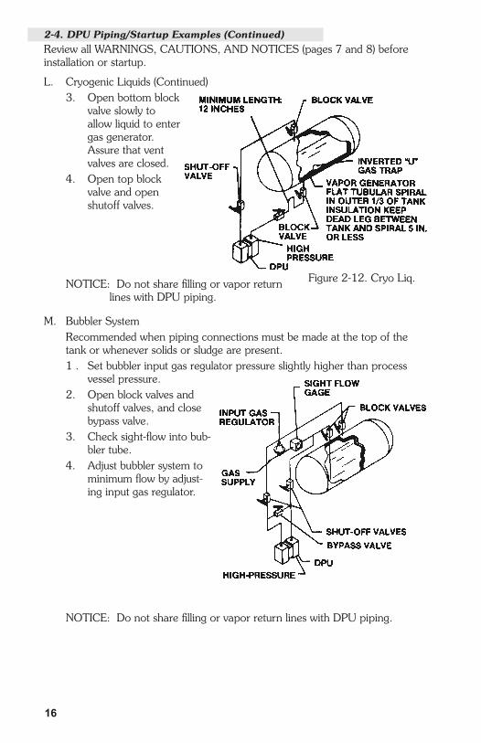
L.. Cryogenic.Liquids. Instrument.may.be.located.above.or.below.the.vessel..The.recommended.
vapor generator is a spiral of 3/8-inch tubing. Install the inverted "U" shaped.gas.trap.inside.vessel..Meters.for.oxygen.service.are.specially.cleaned.and.packaged.in.polyethylene.bags,.and.must.be.kept.extremely.clean.1.. Close.shutoff.valves.2.. Open.drain.valve.and.DPU.housing.drain.plugs.to.remove.all.liquid.
from.system,.and.close.drains.(continued on next page...)
2-4. DPU Piping/Startup Examples (Continued)Review all WARNINGS, CAUTIONS, AND NOTICES (pages 7 and 8) before installation.or.startup.
Figure.2-11..Liq..CO2
16
L. Cryogenic Liquids (Continued)3.. Open.bottom.block.
valve.slowly.to.allow.liquid.to.enter.gas.generator..Assure.that.vent.valves.are.closed.
4.. Open.top.block.valve.and.open.shutoff.valves.
NOTICE: Do not share filling or vapor return lines.with.DPU.piping.
M.. Bubbler.System. Recommended.when.piping.connections.must.be.made.at.the.top.of.the.
tank.or.whenever.solids.or.sludge.are.present.1... Set.bubbler.input.gas.regulator.pressure.slightly.higher.than.process.
vessel.pressure.2.. Open.block.valves.and.
shutoff.valves,.and.close.bypass.valve.
3. Check sight-flow into bub-bler.tube.
4.. Adjust.bubbler.system.to.minimum flow by adjust-ing.input.gas.regulator.
NOTICE: Do not share filling or vapor return lines with DPU piping.
2-4. DPU Piping/Startup Examples (Continued)Review all WARNINGS, CAUTIONS, AND NOTICES (pages 7 and 8) before installation.or.startup.
Figure.2-12..Cryo.Liq.

1�
N. Liquid Specific Gravity This method is for determining specific gravity changes in a process media
using.a.differential.pressure.instrument.1... Set.bubbler.input.gas.regulator.pressure.slightly.higher.than.process.
vessel.pressure.2.. Open.block.valves.and.
shutoff.valves,.and.close.bypass.valve.
3. Check sight-flow into bub-bler.tube.
4.. Adjust.bubbler.system.to minimum flow by adjusting digit flow gages throttling.valves.
2-4. DPU Piping/Startup Examples (Continued)Review all WARNINGS, CAUTIONS, AND NOTICES (pages 7 and 8) before installation.or.startup.
Figure.2-14..Liq..Specifc.Gravity

18
(Blank Page)

19
3-1. Required ToolsTool. PurposeScrewdriver. Bracket.Screws50.lb..Torque.wrench. Pressure.housing.bolts
3-2. Test/Calibration Equipment
3-3. Preventative Maintenance•. DPU.Piping.—.Periodically.inspect.the.integrity.of.the.DPU.piping..Tighten.
all.pipe.joints.as.necessary.•.. DPU.Inspection.and.Cleaning.—.See.DPU.Cleaning.and.Inspection.Proce-
dure.that.follows.
3-4. CalibrationFor.calibration.procedures,.refer.to.separate.actuated.instrument.manual.
3-5. DPU Cleaning and Inspection
WARNING(High Pressure Gas Installations
with pressures greater than 200 psig)HIGH.PRESSURE.GAS.HAZARD.ON.DISASSEMBLY.OF.DPU..TO.PREVENT.POSSIBLE.SEVERE.PERSONAL.INJURY,.DEATH,..OR.SUBSTANTIAL.PROPERTY.DAMAGE.DUE.TO.THE.RELEASE.OF.INTERNAL.PRESSURE,..PERFORM.THE.PRESSURE.CHECK.PROCEDURE THAT FOLLOWS (Step A) BEFORE REMOVING THE.DPU.HOUSING.BOLTS.
WARNINGTHE.DPU.MAY.BE.UNDER.PRESSURE..ENSURE.THAT.THE.PIPING.SYSTEM.IS.COMPLETELY.DEPRESSURIZED.BEFORE.REMOVING.THE.METER.FOR.MAINTENANCE.OR.INSPECTION.(Continued on next page...)
SECTION 3 - MAINTENANCE
Figure.3-1..Test/Calibration.Setup

�0
3-5. DPU Cleaning and Inspection (Continued)(See WARNINGS on page 19 before proceeding.)
WARNING.(Housing Bolts)
DO.NOT.REUSE.HOUSING.BOLTS..IF.BOLTS.ARE.DISTURBED,.REPLACE.WITH.NEW.BOLTS,.PER.TABLE.3-1.REUSE.OF.HOUSING.BOLTS,.ESPECIALLY.IN.CRITICAL.APPLICATIONS.LIKE.HYDROGEN.SULFIDE.AND.SALT.WATER.EXPOSURES,.CAN.RESULT.IN.SEVERE.INJURY,.DEATH.OR.SUBSTANTIAL.PROPERTY.DAMAGE.DUE.TO.BOLT.FAILURE.
NOTICEIf. accumulation. of. solids. or. semi-solids. is. extensive,. remove. the.housings.carefully.to.prevent.damage.to.the.bellows.
A.. Pressure.Check
WARNINGFAILURE.TO.PERFORM.THIS.PROCEDURE.CAN.RESULT.IN.SEVERE.INJURY,.DEATH.OR.SUBSTANTIAL.PROPERTY.DAMAGE.DUE.TO.THE.RELEASE.OF.INTERNAL.PRESSURE.
. This.procedure.should.be.performed.prior.to.removing.the.DPU.housing.bolts,.especially.if.the.DPU.has.been.installed.in.gas.applications.with.work-ing.pressures.greater.than.200.psig.1.. Back.off.all.housing.bolts.4.turns.2.. Check.for.internal.pressure.by.attempting.to.move.the.housing.in.and.
out.along.the.bolts.a.. If.the.housing.moves.freely.—.no.pressure.is.present.—.servicing.
or.repair.may.continue.b.. If.the.housing.does.not.move.freely.—.the.bellows.may.be.pressur-
ized.and.is.POTENTIALLY.HAZARDOUS.if.further.disassembled.. Tighten.the.bolts.and.return.the.unit.to.the.factory.or.authorized.
service.center.for.repair.. Tag.the.unit.and.specify.“Gas.in.Bellows”.
B.. Cleaning/Inspection.Procedure. Instruments.used.in.services.where.solids.or.semi-solids.may.accumulate.
inside.the.pressure.housings.require.periodic.inspection.and.cleaning,.as.follows.1.. Remove.the.DPU.from.service.and.remove.the.pressure.housings.2.. Carefully.remove.the.pressure.housings.from.the.bellows.unit.assembly.
NOTICEIf.the.accumulation.of.material.inside.the.housing.is.extensive,.rapid.removal.of.the.housing.may.damage.the.bellows.convolutions.

�1
3.. Remove.the.accumulation.from.between.the.bellows.convolutions.and.from.the.inside.of.the.housings...Use.a.solvent.if.possible...Do.not.use.a.sharp.instrument.to.clean.between.convolutions.
4.. Assure.that.there.are.no.broken.range.springs.5.. Replace.the.housings.and.O-rings.6. Review Housing Bolt WARNING (page 20) before proceeding. See
Table 3-1 (below and page 22) for pressure housing bolt size, material, part.number,.and.torque.values.
Table.3-1..Bolt.Torque.Ratings
HOUSING BOLTLUBE
(Note 1)
TORQUELB-FT
(Note �)
ROTATION (Degrees) (Note �)SWP MATL. MATL. SIZE PART NO.
400 ALUM(Note 6) STEEL 1/4-28 x 2 0220-0035J NO 8-10 135
400 ALUM(Note 6) 18-8 1/4-28 x 2 0220-1016J NO 8-10 135
500 BRASS STEEL 1/4-28 x 2 0220-0035J NO 8-10 135
500 BRASS 18-8(Note 5) 1/4-28 x 2 0220-1010J YES 10-12 450
500 BRASS K-MONEL 1/4-28 x 2 0220-1018J YES 8-10 180
500 STEEL STEEL 1/4-28 x 2.5 0220-0029J NO 12-14 180
500 SST 17-4 PH 1/4-28 x 2.5 0220-1017J YES 12-14 180
500 SSTA286
(Salt Spray & NACE)
1/4-28 x 2.5 0220-1112J YES 16-18 —
500 SST STEEL (NACE) 1/4-28 X 1/2 S408-0067Z NO 12 —
500 Cu-Ni K-MONEL 1/4-28 x 2.5 0220-0045J YES 9-11 180
1,000 Cu-Ni K-MONEL 1/4-28 x 2.5 0220-0045J YES 9-11 180
1,500 STEEL STEEL 1/4-28 x 2.5 0220-0029J NO 12-14 180
1,500 STEEL K-MONEL 1/4-28 x 2.5 0220-0045J YES 12-14 180
1,500 SST STEEL 1/4-28 x 2.5 0220-0029J NO 12-14 180
1,500 SST 17-4 PH 1/4-28 x 2.5 0220-1017J YES 12-14 180
1,500 SSTA286
(Salt Spray & NACE)
1/4-28 x 2.5 0220-1112J YES 16-18 —
(table continued on next page . . .)
Notes: (1) Lubricant: Lightly apply Molykote G-n paste (0002-0010U) on the first two threads only, unless other-wise specified - do not lube bearing surface. Special applications such as Nuclear, Cryogenic, and oxygen services may require special lubricants. Check BOM for specifics such as thread, head, and gasket surfaces. (�) Torque on bolts is accomplished in 3 or 4 steps. Tighten uniformly. (�) Cameron recommends using a torque wrench whenever installing housing bolts. Rotation of bolt head is measured after bolt is "snug" (approx. 1/16 turn past head contact) with approximately 2 LB-FT torque. Do not exceed this rotation. To tighten bolts without torque wrench, use rotation values. (�) Lube threads per Note 1 and under the head of the MP35N bolts. (5) Denotes for commercial applications only. (6) For reference only - 400 psi ALUM housing is obsolete.
3-5. DPU Cleaning and Inspection (Continued)(See WARNINGS on pages 19 and 20 before proceeding.)
B. Cleaning/Inspection Procedure (Continued)

��
HOUSING BOLTLUBE
(Note 1)
TORQUELB-FT
(Note �)
ROTATION (Degrees) (Note �)SWP MATL. MATL. SIZE PART NO.
3,000 STEEL STEEL 3/8-24 x 2.5 0220-0022J NO 30 90
3,000 SST 17-4 PH 3/8-24 x 1.5 0220-1028J YES 40 90
3,000 SST 17-4 PH 3/8-24 x 3.0 0220-1015J YES 35 90
3,000 SSTA286
(Salt Spray & NACE)
3/8-24 x 2.5 0220-1111J YES 34-36 —
3,000 SST STEEL(NACE) 3/8-24 x 2-1/2 S408-0065Z NO 35 —
3,000 SST 17-4 PH 3/8-24 x 2.5 0220-1014J YES 35 90
3,000 MONEL 17-4 PH 3/8-24 x 2.5 0220-1014J YES 45 180
3,000 MONELA286
(Salt Spray & NACE)
3/8-24 x2.5 0220-1111J YES 19-21 —
6,000 STEEL STEEL 3/8-24 x 2.5 0220-0022J NO 35 135
6,000 SST 17-4 PH 3/8-24 x 2.5 0220-1014J YES 40 135
6,000 SST MP35N(Salt Spray) 3/8-24 x 2.5 0220-1109J (Note 4) 50-52 —
10,000 STEEL STEEL 3/8-24 x 2.5 0220-0022J YES 40 180
10,000 SST 17-4 PH 3/8-24 x 2.5 0220-1014J YES 45 180
10,000 K-MONEL 17-4 PH 3/8-24 x 2.5 0220-1014J YES 45 180
10,000 K-MONEL STEEL 1/2-13 x 3.5 S408-0113C NO 40 180
Notes: (1) Lubricant: Lightly apply Molykote G-n paste (0002-0010U) on the first two threads only, unless other-wise specified - do not lube bearing surface. Special applications such as Nuclear, Cryogenic, and oxygen services may require special lubricants. Check BOM for specifics such as thread, head, and gasket surfaces. (�) Torque on bolts is accomplished in 3 or 4 steps. Tighten uniformly. (�) Cameron recommends using a torque wrench whenever installing housing bolts. Rotation of bolt head is measured after bolt is "snug" (approx. 1/16 turn past head contact) with approximately 2 LB-FT torque. Do not exceed this rotation. To tighten bolts without torque wrench, use rotation values. (�) Lube threads per Note 1 and under the head of the MP35N bolts. (5) Denotes for commercial applications only. (6) For reference only - 400 psi ALUM housing is obsolete.
3-5. DPU Cleaning and Inspection (Continued)(See WARNINGS on pages 19 and 20 before proceeding.)
B. Cleaning/Inspection Procedure (Continued)6. (Continued) Review Housing Bolt WARNING (page 20) before proceeding.
Table 3-1. Bolt Torque Ratings (Continued)

��
3-6. Servicing
Range ChangeTo change the range of the DPU, the bellows unit assembly (BUA) must be replaced.with.a.unit.of.the.desired.range.
BUA.Replacement
WARNINGREVIEW.ALL.WARNINGS,.CAUTIONS,.AND.NOTICES.UNDER.DPU.CLEANING AND INSPECTION (PAGES 19 AND 20) BEFORE PERFORMING THIS.PROCEDURE.
NOTICEDo not loosen drive-arm hold plug (located on the top of the BUA center plate) when removing the mounting bracket. If the plug is loosened, the fill fluid in the bellows.will.be.lost.and.the.unit.will.be.rendered.inoperable.
1.. Disconnect.the.DPU.piping,.remove.the.instrument.from.service,.and.remove.the.mounting.bracket.from.the.DPU.
2... Loosen.the.actuated.instrument.drive.arm.and.separate.it.from.the.torque.tube.shaft..Do.not.disconnect.the.actuated.instrument.linkage.
NOTICESee.the.actuated.instrument's.manual.for.particular.components.that.must.be.removed.to.gain.access.to.the.DPU.mounting.fasteners.
3. Perform Pressure Check Procedure (A) under DPU Cleaning and Inspec-tion.on.page.20...If internal pressure was found, do not continue this procedure.
4.. Remove.pressure.housing.bolts.and.pressure.housings.
NOTICEIt.is.recommended.that.new.O-Rings.be.used.whenever.pressure.hous-ings.are.replaced.
5... Install.the.pressure.housings.onto.the.new.BUA.and.attach.with.appropriate housing bolts (see Table 3-1 for torque requirements).
6. Re-attach DPU (See para. 3-7, page 24 for procedure) to the actuated instrument..
NOTICE(Drive Arm/Torque Tube Tightness Test)
For nuclear seismic/high impact qualified units, a tightness test must be.performed.whenever.a.DPU.is.attached.to.an.instrument..See.para..3-8., page 24 for specific instructions.
7. Install the assembled instrument into service (in reverse order of removal) and.calibrate,.per.separate.actuated.instrument.manual.

��
3-7. Attaching Drive Arm to Torque TubeNOTICE
See separate actuated instrument manual for instrument specific details.Drive.Arm.Assembly.Procedure
1.. Slip.drive.arm.over.torque.tube.shaft;.clear.end.of.torque-tube.housing.by.approximately.0.030-inches.before.securing.to.prevent.interference.
2.. To.tighten.drive.arm.assembly.onto.torque-tube.shaft:a.. Support.block/shaft.and.tighten.clamp.screw.until.snug.to.shaft.b.. Still.supporting.block/shaft,.tighten.clamp.screw.an.additional:
•. Sintered:.1/3.to.1/2.turn.(This.screw.can.normally.turn.one.full.revolution before breaking.)
•. Slotted:.1/4.to.1/3.turn.(The.slot.in.the.slotted.clamp.block.should still be open.)
3-8. Drive Arm Tightness Test Procedure (Required for Nuclear Seismic/High Impact Shock Qualified Units)This.procedure.tests.drive.arm.to.torque-tube.attachment.tightness.by.apply-ing torque developed by DPU onto a fixed drive arm. Care should be taken to apply pressure slowly as the torque is being applied to the connection through the torque-tube drive shaft and not the torque-tube itself.With.pointer.at.normal.0%.torque-tube.rotation.position.(max..minimum.scale.position or 0% on a normal 0 to 100% scale unit), adjust drive arm stop bracket (or use alternate means) to prevent pointer from moving (stop bracket interferes with drive arm movement). Note: On reverse acting and split range units, the DPU.must.be.pressurized.to.move.pointer.to.max..minimum.scale.position.and.on.suppressed.units.it.will.be.necessary.to.apply.pressure.to.establish.a.reference.point.to.check.for.“zero”.shift.Pressurize.DPU.as.required.to.full.calibrated.scale.differential.pressure.(100%.of.the full scale range). This achieves 8-degree of torque-tube drive shaft equivalent torque.onto.the.connection.Observe shift in unit “zero” following DPU depressurization (as required) and drive.arm.stop.bracket.readjusting.(to.allow.free.movement.of.the.drive.arm.and.pointer). A downscale (counter-clockwise) shift in “zero” of greater than 1/2% is indicative.of.drive.arm.slippage.necessitating.further.clamp.block.tightening.
TO TIGHTEN
1/8" W RENCH 0163-0044C
CLAMP SCREW
DRIVE ARM
SHAFT
LINK SINTEREDCLAMP BLOCK
CLAMP SCREW
SHAFT
LINK SLOTTEDCLAMP BLOCK
TO TIGHTEN
3/32" ALLEN W RENCH
.03 (approx)
M224/M224C
DRIVE ARM
Figure.3-2..Attaching.Drive.Arm.to.Torque.Tube

�5
SECTION 4 - TROUBLESHOOTING
Note:.See.actuated.instrument.manual.for.additional.troubleshooting.informa-tion.
Table.4-1..Troubleshooting

�6
SECTION 5 - DIMENSIONS
Figure 5-1. 224/224C Dimensional Drawing (Part 1 of 2)(based on 224C-12303, Rev. 00)

��
Figu
re 5
-1. 2
24/2
24C
Dim
ensi
onal
Dra
win
g (C
ontin
ued)
(Par
t 2 o
f 2)
(bas
ed o
n 22
4C-1
2303
, Rev
. 00)

�8
SECTION 6 - PARTS DRAWING/LIST
Figure.6-1..224/224C.DPU.Parts.Drawing

�9
224/224C DPU Parts List (See Notes and NOTICE, page 33)
Table.6-1..224/224C.DPU.Parts.List
Item Description Part.Number Qty.
1 Bellows Unit Assembly, 3/4" or 5/8" Specify -
2 Bellows Unit Assembly, 1-5/8" Specify -
3 Spacer,.Bracket 0224-0302C 1
4 O-Ring,.Housing.Gasket 2
Buna-N 0001-0028R
Viton 0001-0039R
Viton (NACE) 0001-1164R
Viton (10,000 psi units only) 0001-0062R
EPT 0001-1054R
5 Bracket, Mounting (Not for use with Brass Housings) 0273-0001C 2
6 Nut,.Hex,.Steel,.5/16-18.CP 0500-0033J 4
7 Washer, Split Lock, 5/16" Steel 0003-0006K 4
8 2" Pipe Mounting Kit (w/U-bolts, Nuts, & Washer) 0440-0001J 2
9 Not.Used
10 Screw, Hex Hd., 1/4-28 x 1/2" 0116-1011J 8
11 Screw,.Rd..Hd.,.Steel CP, 10-32 x 3/8" 0111-0057J 4
12 Bracket, Flush (500 psi Forged Brass only) 0224-0235B 1
13 Screw, Fil. Hd., SST, 10-32 x 1/2" 0114-0031J 4
14 Washer,.Split.Lock,.#10,.SST 0003-0032K 4
15 Bracket, Universal Mounting (Wall or Yoke Mtg.) 0273-0003C 1
16 Nut,.Hex,.Steel.CP,.1/4-28 0500-0011J 4
17 Washer, Lock, Ext. Tooth, SST, 1/4" 0003-0068K 12
18 Screw, Fl. Hd., Steel CP, 1/4-28 x 1/2" 0112-0018J 4
19 Housing, Pressure (See Note 5) 2
224C.DPU
Brass,.Forged,.500.psi,.1/4.NPT.Ports 224C-1016C
Brass,.Forged.500.psi,.1/8.NPT.Ports 224C-1018C
Steel,.500/1500.psi,.1/4.NPT.Ports 224C-1113C
Steel,.500/1500.psi,.1/4.X.1/2.NPT.Ports 224C-1123C
Steel,.500/1500.psi,.1/2.NPT.Ports 224C-1130C
Steel,.3000/6000.psi,.1/2.X.1/4.NPT.Ports 224C-1108C
Steel,.3000/6000.psi,.1/4.NPT.Ports 224C-1120C
Steel,.3000/6000.psi,.1/2.NPT.Ports 224C-1128C

�0
Item Description Part.Number Qty.
19 Housing, Pressure (See Note 5) (Continued) 2
224C DPU (Continued)
Steel,.10,000.psi,.1/4..NPT.Ports 224C-1049C
Steel,.10,000.psi,.9/16.AMINCO.Ports 224C-1189C
Cu-Ni,.1000.psi,.1/4.NPT.Ports 224C-1021C
Cu-Ni,.1000.psi,.1/2.NPT.Ports 224C-1022C
Cu-Ni,.1000.psi,.1/8.NPT.Ports 224C-1292C
SST,.500/1500.psi,.1/2.NPT.Ports 224C-1032C
SST,.500/1500.psi,.1/4.NPT.Ports 224C-1033C
SST,.500/1500.psi,.3/8.NPT.Ports 224C-1036C
SST,.500/1500.psi,.1/8.NPT.Ports 224C-1238C
SST, 500/1500 psi, 1/4 NPT Ports (NACE) 0224-1621C
SST, 500/1500 psi, 1/4 X 1/2 NPT Ports (NACE) 0224-1626C
SST, 500/1500 psi, 1/2 NPT Ports (NACE) 0224-1697C
SST,.3000/6000.psi,.1/4.NPT.Ports 224C-1040C
SST,.3000/6000.psi,.1/2..NPT.Ports 224C-1041C
SST,.3000/6000.psi,.1/4.X.1/2.NPT.Ports 224C-1042C
SST,.3000/6000.psi,.9/16.AMINCO.Ports 224C-1187C
SST,.3000/6000.psi,.Seal.Welded,.3/4 0224-1641C
SST,.3000/6000.psi,.1/4.X.1/2.NPT.Ports.(NACE)
0224-1637C
Monel,.3000.psi,.1/4.X.1/2.NPT.Ports 224C-1028C
Monel,.3000.psi,.1/2.NPT.Ports 224C-1029C
Monel,.3000.psi,.1/4.NPT.Ports 224C-1121C
Monel, 3000 psi, 1/4 X 1/2 NPT Ports (NACE) 0224-1685C
K-Monel,.10,000.psi,.9/16.AMINCO.Ports 224C-1215C
224 (Non-C Version) DPU (See Note 3)
Brass, Forged, 500 psi, Absolute (No Ports) 0224-1602C
Brass,.Forged,.500.psi,.1/4.NPT.Ports 0224-1532C
Brass,.Forged,.500.psi,.1/8.NPT.Ports 0224-1606C
Steel,.500/1500.psi,.1/4.NPT.Ports 0224-1576C
224/224C DPU Parts List (See Notes and NOTICE, page 33) (Cont.)Table 6-1. 224/224C DPU Parts List (Continued)

�1
224/224C DPU Parts List (See Notes and NOTICE, page 33) (Cont.)Table 6-1. 224/224C DPU Parts List (Continued)
Item Description Part.Number Qty.
19 Housing, Pressure (See Note 5) (Continued) 2
224 (Non-C Version) DPU (See Note 3) (Continued)
Steel,.500/1500.psi,.1/2.NPT.Ports 0224-1577C
Steel, 500/1500 psi, Absolute (No Ports) 0224-1664C
Steel,.500/1500.psi,.3/8.NPT.Ports 0224-1667C
Steel,.500/1500.psi,.1/4.X.1/2.NPT.Ports 0224-1613C
Steel, 3000/6000 psi, Absolute (No Ports) 0224-1715C
Steel,.3000/6000.psi,.1/4.NPT.Ports 0224-1555C
Steel,.3000/6000.psi,.1/2.NPT.Ports 0224-1578C
Steel,.3000/6000.psi,.1/4.X.1/2.NPT.Ports 0224-1607C
Steel,.10,000.psi,.1/4.NPT.Ports 0224-1662C
Steel,.10,000.psi,.9/16.AMINCO.Ports 0224-1663C
SST,.500/1500.psi,.1/4.NPT.Ports 0224-1543C
SST,.500/1500.psi,.1/2.NPT.Ports 0224-1579C
SST,.500/1500.psi,.1/4.X.1/2.NPT.Ports 0224-1610C
SST, 500/1500 psi, Absolute (No Ports) 0224-1618C
SST,.500/1500.psi,.1/4.NPT.Ports,.Nipple.Mod. 0224-1619C
SST,.500/1500.psi,.1/8.NPT.Ports 0224-1675C
SST,.500/1500.psi,.Seal.Welded,.1/2.NPT.Ports 0224-1679C
SST,.500/1500.psi,.3/8.NPT.Ports 0224-1721C
SST, 500/1500 psi, 1/2 NPT Ports (NACE) 0224-1697C
SST, 500/1500 psi, 1/4 NPT Ports (NACE) 0224-1621C
SST,.500/1500.psi,.Seal.Welded,.1/4.NPT.Ports 0224-1622C
SST, 500/1500 psi, 1/4 X 1/2 NPT Ports (NACE) 0224-1626C
SST,.3000/6000.psi,.1/4.NPT.Ports 0224-1556C
SST,.3000/6000.psi,.1/2.NPT.Ports 0224-1580C
SST,.3000/6000.psi,.1/4.X.1/2.NPT.Ports 0224-1608C
SST,.3000/6000.psi,.Seal.Welded,.3/4 0224-1641C
SST,.3000/6000.psi,.9/16.AMINCO.Ports 0224-1645C
SST,.3000/6000.psi,.1/4.X.1/2.Ports,.Nipple.Mod.
0224-1647C

��
Item Description Part.Number Qty.
19 Housing, Pressure (See Note 5) (Continued) 2
224 (Non-C Version) DPU (See Note 3) (Continued)
SST,.3000/6000.psi,.1/4.X.1/2.NPT.Ports.(NACE)
0224-1637C
Cu-Ni,.1000.psi,.1/4.NPT.Ports 0224-1581C
Cu-Ni,.1000.psi,.1/4.X.1/2.NPT.Ports 0224-1616C
Cu-Ni, 1000 psi, Absolute (No Ports) 0224-1651C
Cu-Ni,.1000.psi,.1/2.NPT.Ports 0224-1655C
Monel, 3000 psi, 1/4 X 1/2 NPT Ports (NACE) 0224-1685C
Monel,.3000.psi,.1/4.X.1/2.NPT.Ports 0224-1687C
Monel,.3000.psi,.1/2.NPT.Ports 0224-1696C
20 Spacer,.DPU.Mounting 0224-1547C 1
21 Bolt,.Housing(Refer to Housing Bolt WARINING on page 20.)
Refer.to.Table.3-1,.pg..21/22.for.Part.No.
4
22 Plug,.Pipe/Port 2
Pipe Plug, 1/4" NPT Brass 0224-0100C
Pipe Plug, 1/8" NPT, Brass 0224-0058C
Pipe Plug, 1/8" NPT, SST 0224-1676C
Pipe Plug, 1/4" NPT, Steel CP 0199-0191C
Pipe Plug, 1/4" NPT, Monel 0199-0235C
Pipe Plug, 1/4" NPT, SST 0199-0214C
Pipe Plug, 1/2" NPT, Steel CP 0199-0192C
Pipe Plug, 1/2" NPT, SST 0199-0215C
Pipe Plug, 1/2" NPT, Monel 0199-0234C
Pipe Plug, 3/8" NPT, SST 0605-0010L
23 Screw, 1/4-28 x 5/8", Steel, CP 0111-0033J 4
24 Washer, Lock, Ext. Tooth, SST, 1/4" 0003-0068K 4
25 Bracket, Mounting (Not for use with Brass Housings) 0224-0055C 2
26 Nut,.Hex,.1/4-28,.Steel,.CP 0500-0011J 4
224/224C DPU Parts List (See Notes and NOTICE, page 33) (Cont.)Table 6-1. 224/224C DPU Parts List (Continued)

��
Item Description Part.Number Qty.
27 Washer, Ext. Tooth, 1/4" SST 0003-0068K 4
28 Screw, Fl. Hd., 1/4-28 x 1/2", Steel, CP 0112-0018J 4
Notes:.(1) Typically two Pipe Plugs required, size depends upon ports to be plugged.(2) Stainless steel housing screws are recommended when the instrument is installed in
a.corrosive.environment.(3) Non-C Versions for specific nuclear service applications only.(4) When ordering, please specify model number of instrument. Minimum parts order is
$100.00..For.actuated.instrument.parts,.refer.to.separate.instrument.manual.(5) Housing pressure ratings are for housings only - not DPU or instrument.
NOTICE (Use Identical Replacement Parts)
Always replace parts with identical parts (same material, rating(s), certs, size, etc.), unless otherwise directed by Cameron.
224/224C DPU Parts List (See Notes and NOTICE, below) (Cont.)Table 6-1. 224/224C DPU Parts List (Continued)

��
(Blank Page)

�5
Product Warranty
A.. Warranty Cameron International Corporation ("Cameron") warrants that at the time
of.shipment,.the.products.manufactured.by.Cameron.and.sold.hereunder.will.be.free.from.defects.in.material.and.workmanship,.and.will.conform.to.the specifications furnished by or approved by Cameron.
B.. Warranty.Adjustment(1) If any defect within this warranty appears, Buyer shall notify Cameron
immediately.(2) Cameron agrees to repair or furnish a replacement for, but not install,
any product which within one (1) year from the date of shipment by Cameron.shall,.upon.test.and.examination.by.Cameron,.prove.defec-tive.within.the.above.warranty.
(3) No product will be accepted for return or replacement without the written.authorization.of.Cameron..Upon.such.authorization,.and.in.accordance.with.instructions.by.Cameron,.the.product.will.be.returned.shipping.charges.prepaid.by.Buyer..Replacements.made.under.this.warranty.will.be.shipped.prepaid.
C..Exclusions.from.Warranty(1) THE FOREGOING WARRANTY IS IN LIEU OF AND EXCLUDES ALL
OTHER.EXPRESSED.OR.IMPLIED.WARRANTIES.OF.MERCHANTABIL-ITY,.OR.FITNESS.FOR..A.PARTICULAR.PURPOSE,.OR.OTHERWISE.
(2) Components manufactured by any supplier other than Cameron shall bear only.the.warranty.made.by.the.manufacturer.of.that.product,.and.Cameron.assumes.no.responsibility.for.the.performance.or.reliability.of.the.unit.as.a.whole.
(3) "In no event shall Cameron be liable for indirect, incidental, or consequen-tial.damages.nor.shall.the.liability.of.Cameron.arising.in.connection.with.any.products.sold.hereunder.(whether.such.liability.arises.from.a.claim.based on contract, warranty, tort, or otherwise) exceed the actual amount paid by Buyer to Cameron for the products delivered hereunder."
(4) The warranty does not extend to any product manufactured by Cameron which.has.been.subjected.to.misuse,.neglect,.accident,.improper.installation.or.to.use.in.violation.of.instructions.furnished.by.Cameron.
(5) The warranty does not extend to or apply to any unit which has been repaired.or.altered.at.any.place.other.than.at.Cameron's.factory.or.service.locations.by.persons.not.expressly.approved.by.Cameron.
Product Brand
Barton®.is.a.registered.trademark.of.Cameron.International.Corporation..("Cameron").

Formerly: NuFlo Measurement Systems • Barton Instrument Systems • Caldon, Inc.
M E A S U R E M E N T S Y S T E M S
U S A • C A N A D A • U K • S C O T L A N D • C H I N A • U A EA L G E R I A • M A L A Y S I A • S I N G A P O R E • w w w . c - a - m . c o m / f l o
EUROPE,MIDDLE EAST
& AFRICA
ASIAPACIFIC
NORTHAMERICA
281.582.9500HOUSTONHEAD OFFICE