Embed Size (px)
Citation preview
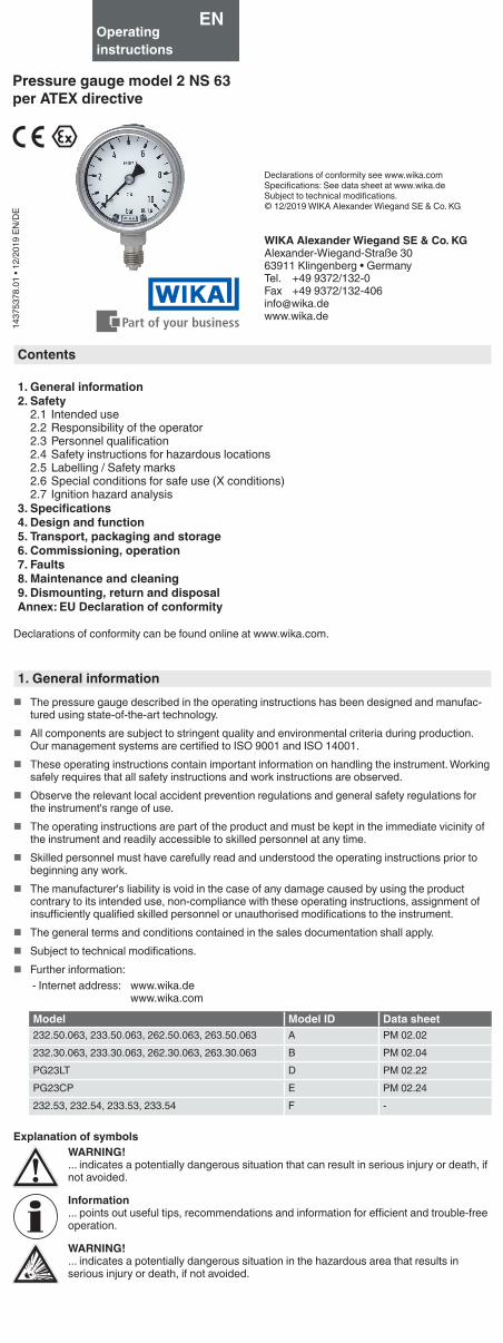
WIKA Alexander Wiegand SE & Co. KGAlexander-Wiegand-Straße 3063911 Klingenberg • GermanyTel. +49 9372/132-0Fax +49 9372/[email protected]
1437
5378
.01
• 12/
2019
EN
/DE
Contents
1. General information2. Safety
2.1 Intended use2.2 Responsibility of the operator2.3 Personnel qualification2.4 Safety instructions for hazardous locations2.5 Labelling / Safety marks2.6 Special conditions for safe use (X conditions)2.7 Ignition hazard analysis
3. Specifications4. Design and function5. Transport, packaging and storage6. Commissioning, operation7. Faults8. Maintenance and cleaning9. Dismounting, return and disposalAnnex: EU Declaration of conformity
Declarations of conformity can be found online at www.wika.com.
1. General information � The pressure gauge described in the operating instructions has been designed and manufac-
tured using state-of-the-art technology. � All components are subject to stringent quality and environmental criteria during production.
Our management systems are certified to ISO 9001 and ISO 14001. � These operating instructions contain important information on handling the instrument. Working
safely requires that all safety instructions and work instructions are observed. � Observe the relevant local accident prevention regulations and general safety regulations for
the instrument's range of use. � The operating instructions are part of the product and must be kept in the immediate vicinity of
the instrument and readily accessible to skilled personnel at any time. � Skilled personnel must have carefully read and understood the operating instructions prior to
beginning any work. � The manufacturer's liability is void in the case of any damage caused by using the product
contrary to its intended use, non-compliance with these operating instructions, assignment of insufficiently qualified skilled personnel or unauthorised modifications to the instrument.
� The general terms and conditions contained in the sales documentation shall apply. � Subject to technical modifications. � Further information:
- Internet address: www.wika.dewww.wika.com
Model Model ID Data sheet232.50.063, 233.50.063, 262.50.063, 263.50.063 A PM 02.02232.30.063, 233.30.063, 262.30.063, 263.30.063 B PM 02.04PG23LT D PM 02.22PG23CP E PM 02.24232.53, 232.54, 233.53, 233.54 F -
Explanation of symbolsWARNING!... indicates a potentially dangerous situation that can result in serious injury or death, if not avoided.
Information... points out useful tips, recommendations and information for efficient and trouble-free operation.
WARNING!... indicates a potentially dangerous situation in the hazardous area that results in serious injury or death, if not avoided.
Operating instructions
Pressure gauge model 2 NS 63per ATEX directive
EN
Declarations of conformity see www.wika.comSpecifications: See data sheet at www.wika.deSubject to technical modifications.© 12/2019 WIKA Alexander Wiegand SE & Co. KG
2. SafetyWARNING!Before installation, commissioning and operation, ensure that the appropriate pressure gauge has been selected in terms of measuring range, design and specific measuring conditions.
Check the compatibility with the medium of the materials subjected to pressure!
In order to guarantee the measurement accuracy and long-term stability specified, the corresponding load limits must be observed.
Non-observance can result in serious injury and/or damage to property.
Further important safety instructions can be found in the individual chapters of these operating instructions.
2.1 Intended useThese pressure gauges are used for measuring pressure in hazardous areas of industrial appli-cations.
Classification per European pressure equipment directive � Instrument type: Pressure accessory without safety function � Media: Liquid or gaseous, group 1 (dangerous) � Maximum permissible pressure PS, see chapter 2.5 “Labelling / safety marks” � Volume: < 0.1 l
The instrument must only be used with media which are not harmful to the wetted parts over the entire operating range of the instrument. Any change in the state of the matter or any decomposi-tion of unstable media is not permitted.Only use the instrument in applications that lie within its technical performance limits (e.g. max. ambient temperature, material compatibility, ...).
→ For performance limits see chapter 9 “Specifications”.
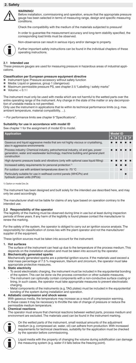
Suitability for use in accordance with model IDSee chapter 1 for the assignment of model ID to model.
Application Model IDA B D E F
Gaseous and liquid aggressive media that are not highly viscous or crystallising, also in aggressive environments
Process industry: Chemical industry, petrochemical industry, oil and gas, power generation, water and wastewater technology, machine building and general plant construction
High dynamic pressure loads and vibrations (only with optional case liquid filling)
Increased safety requirements for personal protection 1)
For outdoor use with ambient temperatures down to -70 °C
Particularly suitable for use in wellhead control panels (WHCPs) and hydraulic power units (HPUs)
1) Option or model 2xx.3x
The instrument has been designed and built solely for the intended use described here, and may only be used accordingly.
The manufacturer shall not be liable for claims of any type based on operation contrary to the intended use.
2.2 Responsibility of the operatorThe legibility of the marking must be observed during time in use but at least during inspection periods of three years. If any harm of the legibility is found please contact the manufacturer to renew the marking.
For the safety of the system, the operator is obliged to carry out an ignition source analysis. The responsibility for classification of zones lies with the plant operator and not the manufacturer/supplier of the equipment.
These ignition sources must be taken into account for the instrument:
1. Hot surfacesThe surface of the instrument can heat up due to the temperature of the process medium. This depends on the installation situation and must be taken into account by the operator.
2. Mechanically generated sparksMechanically generated sparks are a potential ignition source. If the materials used exceed a total mass percentage of 7.5 % magnesium, titanium and zirconium, the operator must take appropriate protective measures.
3. Static electricity - To avoid electrostatic charging, the instrument must be included in the equipotential bonding of the system. This can be done via the process connection or other suitable measures.
- The instrument can optionally contain components with a non-conductive surface coating or lining. In such cases, the operator must take appropriate measures to prevent electrostatic charging.
- Metal components of the instruments (e.g. TAG plates) must be included in the equipotential bonding of the system during installation and operation.
4. Adiabatic compression and shock wavesWith gaseous media, the temperature may increase as a result of compression warming. In these cases it may be necessary to throttle the rate of change of pressure or reduce the permissible medium temperature.
5. Chemical reactionsThe operator must ensure that chemical reactions between wetted parts, process medium and environment are excluded. The materials used can be found in the instrument marking.
On the wetted parts of the instrument, small residual amounts of the adjustment medium (e.g. compressed air, water, oil) can adhere from production. With increased requirements for technical cleanliness, suitability for the application must be checked by the operator before commissioning.
Liquid media with the property of changing the volume during solidification can damage the measuring system (e.g. water if it falls below the freezing point).
2.3 Personnel qualificationWARNING!Risk of injury should qualification be insufficient!Improper handling can result in considerable injury and damage to property.
▶ The activities described in these operating instructions may only be carried out by skilled personnel who have the qualifications described below.
Skilled personnelSkilled personnel are understood to be personnel who, based on their technical training, knowledge of measurement and control technology and on their experience and knowledge of country-specific regulations, current standards and directives, are capable of carrying out the work described and independently recognising potential hazards.
2.4 Safety instructions for hazardous locations
WARNING!Non-observance of these instructions and their contents may result in the loss of explo-sion protection.
WARNING!It is imperative that the application conditions and safety requirements of the EU-type examination certificate are followed.
▶ Pressure gauges must be grounded via the process connection.For use in ambient temperatures below the freezing point of water, filled instruments are recommended. The case filling prevents the formation of and freezing of condensation in the case.
Permissible ambient temperatureModel 232/262/PG23CP: -40 ... +60 °C (unfilled)Model 233/263/PG23CP: -20 ... +60 °C (glycerine filling)
-40 ... +60 °C (silicone oil filling)Model PG23LT: -70 ... +60 °C (silicone oil filling)
Attention! With gaseous media, the temperature may increase as a result of compression warming. In these cases it may be necessary to throttle the rate of change of pressure or reduce the permissible medium temperature.Permissible medium temperature≤ 100 °C (with case filling)≤ 200 °C (unfilled)The permissible medium temperature does not only depend on the instrument design, but also on the ignition temperature of the surrounding gases, vapours or dusts. Both aspects have to be taken into account.Maximum surface temperatureThe surface temperature of the instruments mainly depends on the medium temperature of the application. The instrument itself does not contain any heat sources. For determining the maximum surface temperature, besides the medium temperature also other influences such as the ambient temperature and, if applicable, the solar irradiation must be taken into account. For prevention, consider the maximum medium temperature as maximum surface temperature, if it is not possible to determine the real surface temperature even in the case of expected malfunctions. For prevention, consider the maximum medium temperature as maximum surface temperature, if it is not possible to determine the real surface temperature even in the case of expected malfunctions.
Potentially explosive gas atmosphereRequired temperature class (ignition tempera-ture of gas or vapour)
Maximum permissible surface temperature of the instrument (for the end application)Models 232, 262, PG23CP (unfilled instruments)
Models 233, 263, PG23LT, PG23CP (filled instruments)
T6 (T > 85 °C) +65 °C +65 °CT5 (T > 100 °C) +80 °C +80 °CT4 (T > 135 °C) +105 °C +100 °CT3 (T > 200 °C) +160 °C +100 °CT2 (T > 300 °C) +200 °C +100 °CT1 (T > 450 °C) +200 °C +100 °C
Hazardous dust atmosphereFor dusts, the procedure specified in ISO/IEC 80079-20-2 for determining the ignition temperature has to be applied. The ignition temperature is determined separately for dust clouds and dust layers, respectively. For dust layers, the ignition temperature depends on the dust layer thickness per IEC/EN 60079-14.Ignition temperature of dust
Maximum permissible surface temperature of the instrument (for the end application)
Dust cloud: Tcloud < 2/3 Tcloud
Dust layer: Tlayer < Tlayer − 75 K − (reduction depending on the layer thickness)
The permissible maximum medium temperature must not exceed the lowest determined value, even in case of a malfunction.
Explosive atmosphere consisting of hybrid mixturesThe instruments must not be used in areas in which an atmosphere consisting of explosive hybrid mixtures (dusts mixed with gases) can occur.
Handling of materialsAvoid exposing the instrument to any substances or environmental conditions that could negatively affect the instrument and the materials used. Avoid handling substances that are liable to sponta-neous combustion. For a list of the materials used, see chapter 8 “Specifications”. The materials of the wetted parts are stated on the dial.
CleaningClean the measuring instrument with a moist cloth. Ensure that due to the cleaning no electrostatic charge will be generated.
Special hazardsWARNING!For hazardous media such as oxygen, acetylene, flammable or toxic gases or liquids, and refrigeration plants, compressors, etc., in addition to all standard regulations, the appropriate existing codes or regulations must also be followed.With pressure gauges which do not correspond to a safety version per EN 837 highly pressurised media might leak out through the possibly bursting window in case of a component failure.
For gaseous media and operating pressures > 25 bar a pressure gauge with safety version S3 is recommended per EN 837-2.
WARNING!Residual media in dismounted pressure gauges can result in a risk to persons, the environment and equipment.Take sufficient precautionary measures.
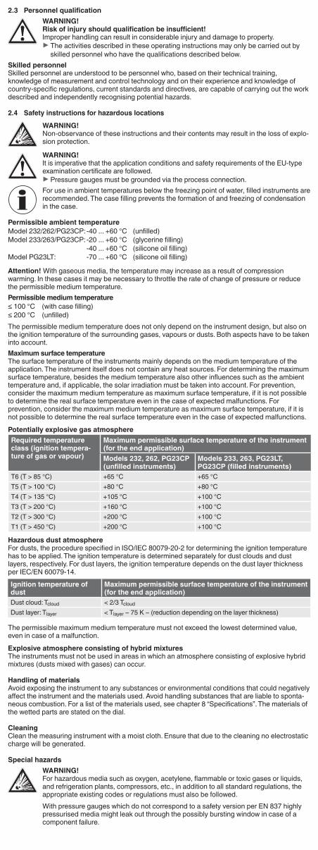
Ex markingEx marking per 2014/34/EU Ex marking per ISO 80079-36/37
A B C D E 1 2 3 4 5 6II 2 G Ex h IIC T6 ... T1 Gb XII 2 D Ex h IIIC T85°C ... T450°C Db X
ID Marking Designation MeaningA CE marking European conformity
B Specific marking for explosion protection
Ex symbol
C II Symbol of the equipment group
Equipment intended for use in other places than underground parts of mines, and in those parts of surface installations of such mines, liable to be endangered by firedamp and/or com-bustible dust and an explosive atmosphere.
D 2 Symbol of the equipment category
High safety, approved for zone 1 and 21
E G Ex atmosphere For areas in which explosive gas, vapour, mist or air mixtures are present.
D Ex atmosphere For areas in which explosive atmospheres caused by dust can form.
1 Ex Ex marking Standards ISO 80079-36 and ISO 80079-37 applied
2 h Ignition protection type
Non-electrical equipment for use in explosive atmospheresAn ignition protection type is not applied to the letter “h”.
3 IIC Suitable atmosphere Gas atmosphere group IICIIIC Combustible flyings, non-conductive dust and conductive dust
4 TX Maximum surface temperature
Symbol indicating the temperature classThe actual maximum surface temperature depends not on the equipment itself, but mainly on the operating conditions.
5 Gb EPL equipment protection level
Potential ignition sources that are effective or may become effective during normal operation and expected malfunction.Db
6 X Specific conditions of use, see operating instructions
Ambient temperature with special range. Specific conditions of use apply.
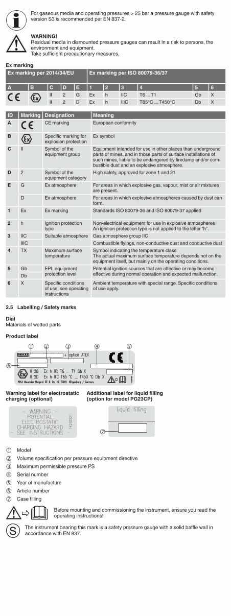
2.5 Labelling / Safety marks
DialMaterials of wetted parts
Product label
Warning label for electrostatic charging (optional)
Additional label for liquid filling (option for model PG23CP)
Model Volume specification per pressure equipment directive Maximum permissible pressure PS Serial number Year of manufacture Article number Case filling
Before mounting and commissioning the instrument, ensure you read the operating instructions!
The instrument bearing this mark is a safety pressure gauge with a solid baffle wall in accordance with EN 837.
2.6 Special conditions for safe use (X conditions)1. All accessories (e.g. valves or attachment components) must be assessed in combination with
the delivered instruments by the end user.2. The operator must recognise ignition hazards and take suitable protective measures. See
chapter 2.2 “Responsibility of the operator”.3. The legibility of the marking must be observed during time in use but at least during inspection
periods of three years. See chapter 2.2 “Responsibility of the operator”.4. For instruments with marking pointer, ensure that there are no electrostatic charging mecha-
nisms at the marking pointer.5. Avoid any kind of external impact. External impacts can generate sparks through friction
processes between different materials.6. The filling/refilling of instruments by non-authorised personnel leads to a loss of the explosion
protection and can lead to damage to the instrument.
2.7 Ignition hazard analysisRelevant identified igni-tion hazards
Implemented protective measures
Hot surfaces ■ The actual surface temperature depends on the application, i.e. on the medium temperature
■ Temperature range marking; T range marking ■ Observation of legibility of marking ▶ Information given in operating instructions
Mechanically generated sparks and hot surfaces
■ Low contact speed ■ Limitation of vibration ■ Selection of suitable materials ▶ Information given in operating instructions
Stray electric currents, ca-thodic corrosion protection
■ Grounding via process connection required ▶ Information given in operating instructions
Static electricity ■ No propagating brush discharge ■ All conductive parts bonded ■ Limitation of projected area of non-conductive parts ■ Limitation of layer thickness of non-conductive parts ■ Grounding via process connection required ■ Description of cleaning process ▶ Information given in operating instructions
Exothermic reactions, including self-ignition of dusts
■ Provision of material data of the wetted parts for the customer in order to avoid the use of critical media
▶ Information given in operating instructions
3. SpecificationsPressure limitationModels 232.50, 233.50, 232.30, 233.30, 262.50, 263.50, 262.30, 263.30, 232.53, 232.54, 233.53,
233.54, PG23LT, PG23CP:Steady: 3/4 x full scale valueFluctuating: 2/3 x full scale valueShort time: Full scale value
Temperature effectWhen the temperature of the measuring system deviates from the reference temperature (+20 °C): max. ±0.4 %/10 K of full scale value
Case ingress protection 1) (per IEC/EN 60529)Model 2xx, PG23CP: IP65, IP66Model 2xx.3x and back mount: IP54Model PG23LT for scale range > 0 ... 16 bar: IP66 / IP67Model PG23LT for scale range ≤ 0 ... 16 bar: IP65
For further specifications see WIKA data sheets PM 02.02, PM 02.04, PM 02.22 and/or PM 02.24 and the order documentation.
1) For general use, no ATEX requirement
4. Design and function
Description � Nominal size 63 mm
� The instruments measure the pressure by means of resilient Bourdon tube pressure elements
� The measuring characteristics are in accordance with the EN 837-1 standard
� In accordance with the EN 837-1 standard, pressure gauges with “S3” marking are safety pressure gauges whose enclosing and pressurised components are designed with a solid baffle wall. Models with “S3” marking are 232.30, 233.30, 262.30, 263.30. The models PG23LT and PG23CP are optionally available in an “S3” variant.
Scope of deliveryCross-check scope of delivery with delivery note.
5. Transport, packaging and storage5.1 TransportCheck the instrument for any damage that may have been caused by transport.Obvious damage must be reported immediately.
CAUTION!Damage through improper transportWith improper transport, a high level of damage to property can occur.
▶ When unloading packed goods upon delivery as well as during internal transport, proceed carefully and observe the symbols on the packaging. ▶ With internal transport, observe the instructions in chapter 5.2 “Packaging and storage”.
Shocks can cause small bubbles to form in the fill fluid of filled instruments. This has no effect on the function of the instrument.
5.2 Packaging and storageDo not remove packaging until just before mounting.Keep the packaging as it will provide optimum protection during transport (e.g. change in installa-tion site, sending for repair).
Permissible storage temperature � Models 2xx, PG23CP: -40 ... +70 °C � Model PG23LT: -70 ... +70 °C
6. Commissioning, operationWARNING!Physical injuries and damage to property and the environment caused by media escaping under high pressureWith the pressurisation of the instrument, as a result of poor sealing of the process connection, media under high pressure can escape.Due to the high energy of the media that can escape in the event of a failure, the possi-bility of physical injuries and damage to property exists.
▶ The sealing of the process connection must be carried out expertly and checked for leak tightness.
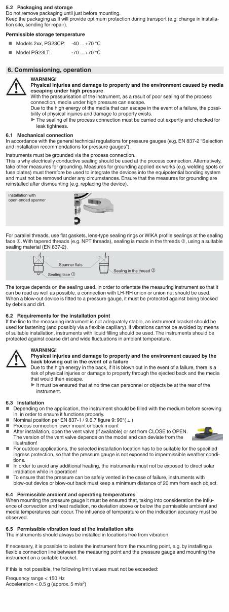
6.1 Mechanical connectionIn accordance with the general technical regulations for pressure gauges (e.g. EN 837-2 “Selection and installation recommendations for pressure gauges”).Instruments must be grounded via the process connection.This is why electrically conductive sealing should be used at the process connection. Alternatively, take other measures for grounding. Measures for grounding applied ex works (e.g. welding spots or fuse plates) must therefore be used to integrate the devices into the equipotential bonding system and must not be removed under any circumstances. Ensure that the measures for grounding are reinstalled after dismounting (e.g. replacing the device).
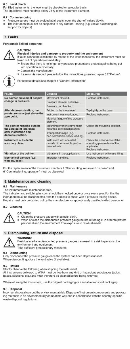
For parallel threads, use flat gaskets, lens-type sealing rings or WIKA profile sealings at the sealing face . With tapered threads (e.g. NPT threads), sealing is made in the threads , using a suitable sealing material (EN 837-2).
The torque depends on the sealing used. In order to orientate the measuring instrument so that it can be read as well as possible, a connection with LH-RH union or union nut should be used.When a blow-out device is fitted to a pressure gauge, it must be protected against being blocked by debris and dirt.
6.2 Requirements for the installation pointIf the line to the measuring instrument is not adequately stable, an instrument bracket should be used for fastening (and possibly via a flexible capillary). If vibrations cannot be avoided by means of suitable installation, instruments with liquid filling should be used. The instruments should be protected against coarse dirt and wide fluctuations in ambient temperature.
WARNING!Physical injuries and damage to property and the environment caused by the back blowing out in the event of a failureDue to the high energy in the back, if it is blown out in the event of a failure, there is a risk of physical injuries or damage to property through the ejected back and the media that would then escape.
▶ It must be ensured that at no time can personnel or objects be at the rear of the instrument.
6.3 Installation � Depending on the application, the instrument should be filled with the medium before screwing
in, in order to ensure it functions properly. � Nominal position per EN 837-1 / 9.6.7 figure 9: 90°( ⊥ ) � Process connection lower mount or back mount � After installation, open the vent valve (if available) or set from CLOSE to OPEN.
The version of the vent valve depends on the model and can deviate from the illustration!
� For outdoor applications, the selected installation location has to be suitable for the specified ingress protection, so that the pressure gauge is not exposed to impermissible weather condi-tions.
� In order to avoid any additional heating, the instruments must not be exposed to direct solar irradiation while in operation!
� To ensure that the pressure can be safely vented in the case of failure, instruments with blow-out device or blow-out back must keep a minimum distance of 20 mm from each object.
6.4 Permissible ambient and operating temperaturesWhen mounting the pressure gauge it must be ensured that, taking into consideration the influ-ence of convection and heat radiation, no deviation above or below the permissible ambient and media temperatures can occur. The influence of temperature on the indication accuracy must be observed.
6.5 Permissible vibration load at the installation siteThe instruments should always be installed in locations free from vibration.
If necessary, it is possible to isolate the instrument from the mounting point, e.g. by installing a flexible connection line between the measuring point and the pressure gauge and mounting the instrument on a suitable bracket.
If this is not possible, the following limit values must not be exceeded:
Frequency range < 150 HzAcceleration < 0.5 g (approx. 5 m/s2)
Installation with open-ended spanner
Spanner flatsSealing in the thread
Sealing face
6.6 Level checkFor filled instruments, the level must be checked on a regular basis.The liquid level must not drop below 75 % of the instrument diameter.
6.7 Commissioning � Pressure surges must be avoided at all costs, open the shut-off valves slowly. � The instrument must not be subjected to any external loading (e.g. use as a climbing aid,
support for objects).
7. Faults
Personnel: Skilled personnel
CAUTION!Physical injuries and damage to property and the environmentIf faults cannot be eliminated by means of the listed measures, the instrument must be taken out of operation immediately.
▶ Ensure that there is no longer any pressure present and protect against being put into operation accidentally. ▶ Contact the manufacturer. ▶ If a return is needed, please follow the instructions given in chapter 8.2 “Return”.
For contact details see chapter 1 “General information”.
Faults Causes MeasuresNo pointer movement despite change in pressure.
Movement blocked. Replace instrument.Pressure element defective.Pressure port blocked.
After depressurisation, the pointer remains just above the zero point.
Friction in the movement. Tap lightly on the case.Instrument was overloaded. Replace instrument.Material fatigue of the pressure element.
The pointer remains outside the zero point tolerance after installation and depressurisation.
Mounting error: Instrument not mounted in nominal position.
Check the mounting position.
Transport damage (e.g. non-permissible shock loading).
Replace instrument.
Instrument outside the accuracy class.
Instrument was operated outside of permissible perfor-mance limits.
Check the observance of the operating parameters of the application.Replace instrument.
Vibration of the pointer. Vibrations in the application. Use instrument with case filling.Mechanical damage (e.g. window, case).
Improper handling. Replace instrument.
For the replacement of the instrument chapters 9 “Dismounting, return and disposal” and 6 “Commissioning, operation” must be observed.
8. Maintenance and cleaning8.1 MaintenanceThe instruments are maintenance-free.The indicator and switching function should be checked once or twice every year. For this the instrument must be disconnected from the process to check with a pressure testing device.Repairs must only be carried out by the manufacturer or appropriately qualified skilled personnel.
8.2 Cleaning
CAUTION! � Clean the pressure gauge with a moist cloth. � Wash or clean the dismounted pressure gauge before returning it, in order to protect
personnel and the environment from exposure to residual media.
9. Dismounting, return and disposalWARNING!Residual media in dismounted pressure gauges can result in a risk to persons, the environment and equipment.Take sufficient precautionary measures.
9.1 DismountingOnly disconnect the pressure gauge once the system has been depressurised!When dismounting, close the vent valve (if available).
9.2 ReturnStrictly observe the following when shipping the instrument:All instruments delivered to WIKA must be free from any kind of hazardous substances (acids, bases, solutions, etc.) and must therefore be cleaned before being returned.
When returning the instrument, use the original packaging or a suitable transport packaging.
9.3 DisposalIncorrect disposal can put the environment at risk. Dispose of instrument components and packag-ing materials in an environmentally compatible way and in accordance with the country-specific waste disposal regulations.

Annex: EU Declaration of conformity