Embed Size (px)
Citation preview
Model 2616RC
T1/E1 TDM Digital Access Concentrator (T-DAC)
Model 3096RC
G.SHDSL TDM Digital Access Concentrator (T-DAC)
Model 3196RC
iDSL TDM T-DAC
Administrator’s Reference Guide
Sales Office:
+1 (301) 975-1000
Technical Support:
+1 (301) 975-1007
E-mail:
WWW:
www.patton.com
Document Number:
11011U3-001 Rev. E
Part Number:
07MD3096RC-ARG
Revised:
April 9, 2009

Patton Electronics Company, Inc.
7622 Rickenbacker DriveGaithersburg, MD 20879 USA
Tel: +1 (301) 975-1000Fax: +1 (301) 869-9293
Support: +1 (301) 975-1007URL: www.patton.com
E-Mail: [email protected]
Copyright Statement
Copyright © 2003–2009, Patton Electronics Company. All rights reserved.
Notices
The information contained in this document is not designed or intended for use ascritical components in human life-support systems, equipment used in hazardousenvironments, or nuclear control systems. Patton Electronics Company disclaims anyexpress or implied warranty of fitness for such uses.
The information in this document is subject to change without notice. Patton Elec-tronics assumes no liability for errors that may appear in this document.
Any software described in this document is furnished under license and may be usedor copied only in accordance with the terms of such license.
3
Summary Table of Contents
1 Introduction.................................................................................................................................................. 33
2 Home............................................................................................................................................................. 36
3 Import/Export ............................................................................................................................................... 44
4 Alarms ........................................................................................................................................................... 48
5 DS0 Mapping................................................................................................................................................ 56
6 System Clocking............................................................................................................................................ 75
7 Ethernet......................................................................................................................................................... 84
8 Frame Relay................................................................................................................................................... 91
9 G.SHDSL (Model 3096RC) ........................................................................................................................ 101
10 iDSL (Model 3196RC)................................................................................................................................ 131
11 In-band management .................................................................................................................................. 149
12 IP (IP, TCP, UDP, & ICMP) ..................................................................................................................... 179
13 IP Filtering .................................................................................................................................................. 207
14 PPP ............................................................................................................................................................. 215
15 RIP Version 2 .............................................................................................................................................. 234
16 SNMP.......................................................................................................................................................... 240
17 System ......................................................................................................................................................... 245
18 Alarm Card.................................................................................................................................................. 272
19 System Log .................................................................................................................................................. 274
20 T1/E1 Link.................................................................................................................................................. 285
21 About........................................................................................................................................................... 311
22 License......................................................................................................................................................... 313

Table of Contents
About this guide...................................................................................................................................................30Audience............................................................................................................................................................... 30Structure............................................................................................................................................................... 30Precautions ........................................................................................................................................................... 31Conventions used in this document...................................................................................................................... 31
General conventions .......................................................................................................................................31Mouse conventions .........................................................................................................................................32
1 Introduction.................................................................................................................................................. 33Introduction ..........................................................................................................................................................34Logging into the HTTP/HTML Web Management windows...............................................................................34HTTP/HTML and SNMP Object Format ...........................................................................................................35Saving HTTP/HTML Object Changes .................................................................................................................35
2 Home............................................................................................................................................................. 36Introduction ..........................................................................................................................................................37Product information box .......................................................................................................................................40Operating status variables ......................................................................................................................................41
Number of T1/E1 Ports (boxEgressCount) .....................................................................................................41% CPU Idle (boxIdleTime) ............................................................................................................................41Running Since Last Boot (sysUpTime) ...........................................................................................................41Chassis Address (cPCIShelfAddr) ....................................................................................................................41Slot Address (cPCISlotID) ..............................................................................................................................41Current Card State (alarmBoxState) ................................................................................................................42Total Card Alarms (alarmTotal) ......................................................................................................................42
Operator Actions ...................................................................................................................................................42Record Current Configuration (storeConfig(1)) .............................................................................................42Hard Reset (hardReset(2)) ..............................................................................................................................42Set Factory Default Configuration (forceDefaultConfig(3)) ............................................................................43
3 Import/Export ............................................................................................................................................... 44Introduction ..........................................................................................................................................................45Export current Flash configuration ........................................................................................................................45Import Flash configuration from file......................................................................................................................47
4 Alarms ........................................................................................................................................................... 48Introduction ..........................................................................................................................................................49Alarm System Overview window ...........................................................................................................................49Alarms management windows ...............................................................................................................................52
Alarm System Configuration window .............................................................................................................52Alarm Syslog Priority (syslogAlarmPriority) ..............................................................................................53Board Temperature Threshold (boxAlarmTemperature) ...........................................................................53Alarm Trap Manager 1 through 4 (alarmTrapIp0–alarmTrapIp3) ............................................................54
4
Models 2616RC, 3096RC & 3196RC Admin Reference Guide
Alarm Severity Configuration .........................................................................................................................54
5 DS0 Mapping................................................................................................................................................ 56Introduction ..........................................................................................................................................................58DS0 Mapping Overview main window..................................................................................................................59DS0 mapping and in-band management ...............................................................................................................60Non-blocking system constraints with in-band management .................................................................................60System design considerations and guidelines..........................................................................................................60DS0 Fallback Configuration window ....................................................................................................................61
Fallback Help button ......................................................................................................................................61Watch the following ports for a failure state ....................................................................................................62
Watch Port Type (daxWatchTypegshDSL) ...............................................................................................62Watch Port Number (daxWatchPortgshDSL) ...........................................................................................62Watch Port Slots (daxWatchSlot) ..............................................................................................................62
Slot Numbering Examples ..................................................................................................................63In case of failure, switch to the following port .................................................................................................63
Fallback Port Type (daxFallbackTypegshDSL) ..........................................................................................64Fallback Port Number (daxFallbackPortGsDS) .........................................................................................64Fallback Port Slots (daxFallbackSlot) .........................................................................................................64Fallback Port Type fromH110(0) (daxFallbackTypegshDSLH110) ..........................................................64Fallback Port Number (daxFallbackPortgshDSLH11) ...............................................................................64Fallback Port Slots (daxFallbackSlotH110) ...............................................................................................65
Port Fallback Table .........................................................................................................................................65Fallback Mapping ID ................................................................................................................................65Recovery Type (daxFallbackRecovery) .......................................................................................................65
DS0 Fallback ID (DAX Fallback ID) window ................................................................................................65Viewing the DS0 Fallback ID window ............................................................................................................65Deleting a Fallback Mapping ..........................................................................................................................66Force Recovery button ....................................................................................................................................66
Display Option parameter .....................................................................................................................................66Mapping Help.......................................................................................................................................................67Configuring static connections using the long form...............................................................................................67
Device Type A (daxDeviceTypeTogshDSL) ....................................................................................................67Device Type B (daxDeviceTypeFromgshDSL) (daxDeviceTypeRxgshDSL) ...................................................68Device Number A (daxDeviceNumberTogshDSL) and Device Number B (daxDeviceNumberFromgshDSL) (daxDeviceNumberRxgshDSL) .................................................................68Device Slots A and B (daxDeviceSlotTo) (daxDeviceSlotFrom) ......................................................................69
Slot Numbering Examples .........................................................................................................................69Defining DS0 mappings using the command line interface (CLI) .........................................................................70
Slot Numbering Examples ..............................................................................................................................71Saving a DS0 mapping definition ..........................................................................................................................72Defined Mappings Table (Static Connections) ......................................................................................................72
ID (daxConnectionID) ...................................................................................................................................72Fallback ..........................................................................................................................................................72
5
Models 2616RC, 3096RC & 3196RC Admin Reference Guide
Type A ............................................................................................................................................................73Port A .............................................................................................................................................................73Slots A ............................................................................................................................................................73Type B ............................................................................................................................................................73Port B .............................................................................................................................................................73Slots B ............................................................................................................................................................73
DS0 Connection ID (DAX Connection ID) window............................................................................................73Viewing the DS0 Connection ID window ......................................................................................................73Deleting a DS0 Mapping ................................................................................................................................74
6 System Clocking............................................................................................................................................ 75Introduction ..........................................................................................................................................................76System Clocking Configuration window ...............................................................................................................77
System Clocking Configuration table ..............................................................................................................77Clock Reference (sysGSClockMode) .........................................................................................................78Main Reference (sysgshDSLClockMainRef) and Fallback Reference (sysgshDSLClockFallbackRef) .........79Clocking Status (sysdaxClockFailure) ........................................................................................................81Fallback Indication (daxFallbackInd) ........................................................................................................81Clock Status ..............................................................................................................................................81Enable/Disable Fallback System ................................................................................................................82Enable/Disable Clock Auto Recover System ..............................................................................................82Saving your work ......................................................................................................................................82
Immediate actions buttons ..............................................................................................................................83
7 Ethernet......................................................................................................................................................... 84Introduction ..........................................................................................................................................................85Ethernet Overview window ...................................................................................................................................85
State (boxEtherAState) ....................................................................................................................................85PrimaryIpAddress (boxEtherAPrimaryIpAddress) ...........................................................................................86PrimaryIpMask (boxEtherAPrimaryIpMask) ...................................................................................................86
PrimaryIpFilters (boxEtherAPrimaryIpFilters) ................................................................................................86SecondaryIpAddress (boxEtherASecondaryIpAddress) ....................................................................................86SecondaryIpMask (boxEtherASecondaryIpMask) ............................................................................................86SecondaryIpFilters (boxEtherASecondaryIpFilters) .........................................................................................86Technique (boxEtherATechnique) ..................................................................................................................86
Ethernet Statistics window.....................................................................................................................................87Alignment Errors (dot3StatsAlignmentErrors) ................................................................................................87FCS Errors (dot3StatsFCSErrors) ...................................................................................................................87Single Collision Frames (dot3StatsSingleCollision Frames) .............................................................................87Multiple Collision Frames (dot3StatsMultipleCollisionFrames) ......................................................................87SQE Test Errors (dot3StatsSQETestErrors) ....................................................................................................87Deferred Transmissions (dot3StatsDeferredTransmissions) .............................................................................87Late Collisions (dot3StatsLateCollisions) ........................................................................................................87Excessive Collisions (dot3StatsExcessiveCollisions) .........................................................................................87Other Errors (dot3StatsInternalMacTransmitErrors) ......................................................................................88
6
Models 2616RC, 3096RC & 3196RC Admin Reference Guide
Carrier Sense Errors (dot3StatsCarrierSenseErrors) .........................................................................................88Received Frames Too Long (dot3StatsFrameTooLongs) .................................................................................88Other Received Errors (dot3StatsInternalMacReceiveErrors) ..........................................................................88Chip Set ID (dot3StatsEtherChipSet) .............................................................................................................88
Ethernet Configuration window............................................................................................................................88State (boxEtherAState) ....................................................................................................................................88Primary IP settings ..........................................................................................................................................89
PrimaryIpAddress (boxEtherAPrimaryIpAddress) ......................................................................................89PrimaryIpMask (boxEtherAPrimaryIpMask) .............................................................................................89PrimaryIpFilters (boxEtherAPrimaryIpFilters) ...........................................................................................89
Secondary IP settings ......................................................................................................................................89SecondaryIpAddress (boxEtherASecondaryIpAddress) ...............................................................................89SecondaryIpMask (boxEtherASecondaryIpMask) ......................................................................................89SecondaryIpFilters (boxEtherASecondaryIpFilters) ....................................................................................90
Technique (boxEtherATechnique) ..................................................................................................................90
8 Frame Relay................................................................................................................................................... 91Introduction ..........................................................................................................................................................93Configuring a Frame Relay link.............................................................................................................................93T1/E1 port and DS0 selection...............................................................................................................................93The Frame Relay main window.............................................................................................................................94
Link X (frDlcmiIfIndex) .................................................................................................................................95Status: X (framerelStatus) ..........................................................................................................................95
HDLC Statistics on Link ................................................................................................................................95Transmit (Bits/Sec) (framerelTxOctets) ....................................................................................................95Receive (Bits/Sec) (framerelRxOctets) .......................................................................................................95No Buffers Available (framerelRxNoBufferAvailable) ................................................................................95Data Overflow (framerelRxDataOverflow) ................................................................................................95Message Ends (framerelRxMessageEnds) ...................................................................................................96Packets Too Long (framerelRxPacketTooLong) ........................................................................................96
Overflow (framerelRxOverflow) ................................................................................................................96Aborts (FramerelRxAbort) .........................................................................................................................96Bad CRC (framerelRxBadCrc) ..................................................................................................................96Invalid Frames (framerelRxInvalidFrame) .................................................................................................96Tx Underrruns (framerelTxUnderrun) ......................................................................................................96LINK Resets (framerelResets) ....................................................................................................................96Produce Status Change Trap (frTrapState) ................................................................................................96
DLMI window ......................................................................................................................................................96Signalling (frDlcmiState) ................................................................................................................................97Data Link Protocol (frDlcmiAddress) .............................................................................................................97DLCI Length (frDlcmiAddressLen) ................................................................................................................97Polling Interval (T391)(frDlcmiPollingInterval) .............................................................................................97Full Enquiry Interval (N391)(frDlcmiFullEnquiryInterval) ............................................................................98Error Threshold (N392)(frDlcmiErrorThreshold) ..........................................................................................98
7
Models 2616RC, 3096RC & 3196RC Admin Reference Guide
Monitored Events (N393)(frDlcmiMonitoredEvents) ....................................................................................98MultiCast Service (frDlcmiMulticast) .............................................................................................................98Max Virtual Circuits (frDlcmiMaxSupportedVCs) .........................................................................................98LMI Interface (frDlcmiInterface) ....................................................................................................................98Bidirectional Polling (frDlcmiPollingBiDir) ...................................................................................................98Polling Verification (T392)(frDlcmiPollingVerification) ................................................................................98
DLCI window .......................................................................................................................................................98DLCI (frCircuitDlci) ......................................................................................................................................99Interface # (FrameIPInterfaceNum) ................................................................................................................99State (frCircuitState) .......................................................................................................................................99Committed Burst (bits) (frCircuitCommitedBurst) ......................................................................................100Excess Burst (bits) (frCircuitExcessBurst) ......................................................................................................100Throughput (bits) (frCircuitThroughput) .....................................................................................................100IP Address (FrameIPAddr) ............................................................................................................................100Congestion (frameEnableCongestion) ...........................................................................................................100
9 G.SHDSL (Model 3096RC) ........................................................................................................................ 101Introduction ........................................................................................................................................................103G.SHDSL Port Configuration window ...............................................................................................................103
G.SHDSL port summary status ....................................................................................................................104Operator action buttons ................................................................................................................................105G.SHDSL port status ....................................................................................................................................106
Port # (gshDSLPortNum) .......................................................................................................................106Circuit ID (gshDSLCircuitID) ................................................................................................................106State (gshDSLState) ................................................................................................................................107
Clearing an error condition ...............................................................................................................107Color-coded port status indicators ...........................................................................................................108Desired State (gshDSLDesireState) .........................................................................................................108Test Mode (sDSLTMSelection) ..............................................................................................................108Test Pattern (gshDSLPattSelect) .............................................................................................................110
Payload Rate (gshDSLPayloadRate) ........................................................................................................112Error Code (gshDSLErrorCode) .............................................................................................................112Saving your work ....................................................................................................................................112
G.SHDSL Port Details window...........................................................................................................................113Operator action buttons ................................................................................................................................114G.SHDSL port status and statistics tables .....................................................................................................116
General Info table ...................................................................................................................................116Activation State Info table .......................................................................................................................117Fifo Info table .........................................................................................................................................118Data Path Info table ................................................................................................................................118History Details table ...............................................................................................................................119
Port configuration tables ...............................................................................................................................120Change Config button ............................................................................................................................121Cancel button .........................................................................................................................................121
8
Models 2616RC, 3096RC & 3196RC Admin Reference Guide
CO Configuration table ................................................................................................................................121CPE Configuration table ..............................................................................................................................123Additional CPE parameters ...........................................................................................................................124Hardware Loop Status Parameters .................................................................................................................125Saving your work ..........................................................................................................................................126Hard Reset This Port button .........................................................................................................................126
G.SHDSL Port History of Near-End Performance window ................................................................................127Back To System History Page hyperlink .......................................................................................................128To Port Details Page hyperlink .....................................................................................................................128Error Statistics table ......................................................................................................................................128
G.SHDSL Line Provision window.......................................................................................................................129Back button ..................................................................................................................................................129Refresh Current Page button .........................................................................................................................129Calculate Best Line Rate button ....................................................................................................................130Cancel button ...............................................................................................................................................130
10 iDSL (Model 3196RC)................................................................................................................................ 131Introduction ........................................................................................................................................................132iDSL Port Configuration window .......................................................................................................................132
iDSL Port Summary Status ...........................................................................................................................133Operator action buttons ................................................................................................................................134iDSL port status ............................................................................................................................................134
Port Number (idslPortNum) ...................................................................................................................134Circuit ID (idslCircuitID) .......................................................................................................................135Current State (idslCurrentState) ..............................................................................................................135
Clearing an error condition ...............................................................................................................135Color-coded port status indicators ...........................................................................................................136Desired State (idslDesireState) .................................................................................................................136Test Mode (idslTMSelection) .................................................................................................................136Test Pattern (idslPattSelect) ....................................................................................................................138
CPE Device (idslRemoteModelCode) .....................................................................................................139CPE Circuit ID .......................................................................................................................................139Saving Your Work ...................................................................................................................................139
iDSL Port Details window...................................................................................................................................140Operator action buttons ................................................................................................................................141iDSL port status and statistics tables .............................................................................................................142
iDSL Port Status table .............................................................................................................................142iDSL Port Statistics table .........................................................................................................................143
CPE information and configuration ....................................................................................................................144CPE information ..........................................................................................................................................144CPE configuration ........................................................................................................................................144
iDSL Near End Performance Interval ..................................................................................................................145Back To System History Page hyperlink .......................................................................................................147To Port Details Page hyperlink .....................................................................................................................147
9

Models 2616RC, 3096RC & 3196RC Admin Reference Guide
Error Statistics table ......................................................................................................................................147iDSL Alarm Thresholds Per 15 Minute Interval ............................................................................................148
11 In-band management .................................................................................................................................. 149Overview .............................................................................................................................................................151Introduction ........................................................................................................................................................151
When to use in-band management ................................................................................................................152In-Band Management Overview window ............................................................................................................153Defining a T1/E1 Management Channel ............................................................................................................154
Example 1: T1/E1 Frame Relay Management Channel .................................................................................156Deleting the T1/E1 management channel ...............................................................................................157
Example 2: T1/E1 Routed PPP Management Channel .................................................................................158Deleting the T1/E1 management channel ...............................................................................................159
Example 3: T1/E1 Bridged PPP Management Channel ................................................................................159Deleting the T1/E1 management channel ...............................................................................................160
Defining a Chassis (H.110) Management Channel..............................................................................................160PPP-IPCP Chassis Management Channel............................................................................................................161
Name ............................................................................................................................................................161IP Address (sysMgmtIpAddress) ....................................................................................................................161Direction ......................................................................................................................................................161Port ...............................................................................................................................................................161TimeSlot .......................................................................................................................................................162Default Gateway (sysMgmtDefaultGateway) ................................................................................................162Example 1: Routed PPP (IPCP) Chassis Management Channel ....................................................................164
Define button .........................................................................................................................................164Example 2: Bridged PPP (BCP) Chassis Management Channel ....................................................................165
Defining a G.SHDSL Management Channel ......................................................................................................167IP Addresses—IPCP & BCP .........................................................................................................................167Configure the Model 3096RC for a G.SHDSL in-band management channel ..............................................168Example 1: Configuring a BCP bridged G.SHDSL link for management traffic only ...................................169
Configure Model 3086 for an in-band management channel ..................................................................1703096RC G.SHDSL Management Link Status .........................................................................................171
Example 2: Configuring an IPCP routed G.SHDSL link for management traffic only ..................................172Configure Model 3086 for an in-band management channel ..................................................................1733096RC G.SHDSL Management Link Status .........................................................................................174
The Chassis Management Channel statistics page................................................................................................176Connection ID (sysMgmtConnectionID) .....................................................................................................176Deleting an H.110 in-band management channel .........................................................................................176Connection Details .......................................................................................................................................177
IP Address (sysMgmtIpAddress) ..............................................................................................................177Status (sysMgmtStatus) ...........................................................................................................................177TX Port (sysMgmtPortTx) ......................................................................................................................177Tx TimeSlot (sysMgmtSlotTx) ...............................................................................................................177Rx Port (sysMgmtPortRx) .......................................................................................................................177
10
Models 2616RC, 3096RC & 3196RC Admin Reference Guide
Rx TimeSlot (sysMgmtSlotRx) ................................................................................................................177HDLC Statistics ...........................................................................................................................................177
LINK Resets (sysMgmtResets) ................................................................................................................177Transmit Octets (sysMgmtTxOctets) ......................................................................................................177Transmit Frames (sysMgmtTxMessageEnds) ..........................................................................................177Receive Octets (sysMgmtRxOctets) .........................................................................................................177Receive Frames (sysMgmtRxMessageEnds) .............................................................................................178Receive Frames Too Long (sysMgmtRxPacketTooLong) ........................................................................178Receive Bad CRCs (sysMgmtRxBadCrc) .................................................................................................178Receive Invalid Frames (sysMgmtRxInvalidFrame) .................................................................................178Receive No Buffers Available (sysMgmtRxNoBufferAvailable) ................................................................178
IP Routing table modifications ............................................................................................................................178Recommended troubleshooting if the link does not come UP .............................................................................178
12 IP (IP, TCP, UDP, & ICMP) ..................................................................................................................... 179Introduction ........................................................................................................................................................183IP Overview window ...........................................................................................................................................184
Hyperlinks ....................................................................................................................................................185IP Parameters ................................................................................................................................................185
Forwarding ..............................................................................................................................................185Default Time-To-Live .............................................................................................................................186
IP Statistics ...................................................................................................................................................186Total Datagrams Received .......................................................................................................................186Discarded for Header Errors ....................................................................................................................186Discarded for Address Errors ...................................................................................................................186Forwarded Datagrams .............................................................................................................................186Discarded for Unknown Protos ...............................................................................................................186Discarded with No Errors .......................................................................................................................186Total Deliveries .......................................................................................................................................186Out Requests ..........................................................................................................................................186
Out Discards ...........................................................................................................................................187Discarded for No Routes .........................................................................................................................187Reassembly Timeout ...............................................................................................................................187# of Reassembled Fragments ....................................................................................................................187# Successfully Reassembled ......................................................................................................................187Reassembly Failures .................................................................................................................................187# Fragmented OK ...................................................................................................................................187# Fragmented Failed ................................................................................................................................187# Fragments Created ...............................................................................................................................187# Valid but Discarded .............................................................................................................................188
IP Configuration window....................................................................................................................................188IP Configuration ...........................................................................................................................................188
Forwarding (ipForwarding) .....................................................................................................................188Default Time-To-Live (ipDefaultTTL) ...................................................................................................188
11

Models 2616RC, 3096RC & 3196RC Admin Reference Guide
Saving your work ....................................................................................................................................188IP Addressing Overview window .........................................................................................................................189
IP Address Details window ...........................................................................................................................189Entry Interface Index (ipAdEntIfIndex) ..................................................................................................189Entry Subnet Mask (ipAdEntNetMask) ..................................................................................................189Entry Broadcast Address (ipAdEntBcastAddr) .........................................................................................189Entry Reassembly Maximum Size (ipAdEntReasmMaxSize) ...................................................................190
IP Routing Overview window .............................................................................................................................190Defined Routes .............................................................................................................................................190
Destination (genRouteDest) ....................................................................................................................190Mask (genRouteMask) ............................................................................................................................191Gateway (genRouteGateway) ..................................................................................................................191Cost (genRouteCost) ...............................................................................................................................191Interface (genRouteIfIndex) ....................................................................................................................191Protocol (genRouteProto) .......................................................................................................................191State (RouteState) ...................................................................................................................................191
Defined Routes .............................................................................................................................................192Destination (ipRouteDest) ......................................................................................................................192Mask (ipRouteMask) ...............................................................................................................................192Gateway (genRouteGateway) ..................................................................................................................192
Advanced… ..................................................................................................................................................192Destination (ipRouteDest) ......................................................................................................................192Mask (ipRouteMask) ...............................................................................................................................192Interface (genRouteIfIndex) ....................................................................................................................192
IP Route Details window.....................................................................................................................................193Destination IP Address (genRouteDest) ........................................................................................................193Mask (genRouteMask) ..................................................................................................................................193Interface (genRouteIfIndex) ..........................................................................................................................193Protocol (genRouteProto) .............................................................................................................................193Seconds Since Updated (genRouteAge) .........................................................................................................194Tag (genRouteTag) .......................................................................................................................................194Gateway (genRouteGateway) ........................................................................................................................194Cost (genRouteCost) ....................................................................................................................................194State (genRouteState) ....................................................................................................................................194
IP Routing Table window ...................................................................................................................................194Destination (ipRouteDest) ............................................................................................................................195Mask (ipRouteMask) ....................................................................................................................................195Next Hop (ipRouteNextHop) .......................................................................................................................195Interface (ipRouteIfIndex) ............................................................................................................................195Type (ipRouteType) .....................................................................................................................................195Protocol (ipRouteProto) ................................................................................................................................195Info (ipRouteInfo) ........................................................................................................................................196
IP Address Translation Overview window ...........................................................................................................196Defined Address Correlations .......................................................................................................................196
12
Models 2616RC, 3096RC & 3196RC Admin Reference Guide
Interface (ipNetToMediaIfIndex) ............................................................................................................196Net Address (ipNetToMediaNetAddress) ...............................................................................................197Physical (ipNetToMediaPhysAddress) .....................................................................................................197Type (ipNetToMediaType) ....................................................................................................................197
Define a New Address Correlation ................................................................................................................197TCP Overview window .......................................................................................................................................198
Details… hyperlink .......................................................................................................................................199TCP Parameters ............................................................................................................................................199
Retransmit-Timeout Algorithm (tcpRtoAlgorithm) ................................................................................199Retransmit-Timeout Minimum (tcpRtoMin) .........................................................................................199Retransmit-Timeout Maximum (tcpRtoMax) .........................................................................................199Maximum Connections (tcpMaxConn) ..................................................................................................199
TCP Statistics ...............................................................................................................................................199Active Opens (tcpActiveOpens) ..............................................................................................................199Passive Opens (tcpPassiveOpens) ............................................................................................................199Attempt/Fails (tcpAttemptFails) ..............................................................................................................199ESTABLISHED Resets (tcpEstabResets) ................................................................................................199Current ESTABLISHED (tcpCurrEstab) ................................................................................................200Total Received (tcpInSegs) ......................................................................................................................200Total Sent (tcpOutSegs) ..........................................................................................................................200Total Retransmitted (tcpRetransSegs) .....................................................................................................200Total Received in Error (tcpInErrs) .........................................................................................................200Total Sent w/RST Flag (tcpOutRsts) ......................................................................................................200
TCP Details window ...........................................................................................................................................200TCP Connections .........................................................................................................................................200
Local Port (tcpConnLocalPort) ...............................................................................................................200Remote Address (tcpConnRemAddress) ..................................................................................................200Remote Port (tcpConnRemPort) ............................................................................................................201State (tcpConnState) ...............................................................................................................................201
UDP Overview window ......................................................................................................................................201UDP Statistics ...............................................................................................................................................202
Datagrams Received (udpInDatagrams) ..................................................................................................202Datagrams Received With No Ports (udpNoPorts) .................................................................................202Datagrams Received with No Delivery (udpInErrors) .............................................................................202Datagrams Sent (udpOutDatagrams) ......................................................................................................202
UDP Listener Table (udpTable) ...................................................................................................................202Local Address (udpLocalAddress) ............................................................................................................202Local Port (udpLocalPort) .......................................................................................................................202
ICMP Overview window.....................................................................................................................................203ICMP Parameters .........................................................................................................................................203
ICMP Redirects (boxBlockIcmpRedirects) ..............................................................................................203ICMP Statistics .............................................................................................................................................204
Total ICMP Datagrams Received (icmpInMsgs) .....................................................................................204Total ICMP Datagrams Sent (imcpOutMsgs) .........................................................................................204
13
Models 2616RC, 3096RC & 3196RC Admin Reference Guide
w/Errors (icmpInErrors, icmpOutErrors) ................................................................................................204Destinations Unreachable (IcmpInDestUnreachs, IcmpOutDestUnreachs) ............................................204Times Exceeded (icmpInTimeExcds, icmpOutTimeExcds) .....................................................................205Parameter Problems (icmpInParmProbs, icmpOutParmProbs) ...............................................................205Source Quenchs (icmpInSrcQuenchs, icmpOutSrcQuenchs) ..................................................................205Redirects (icmpInRedirects, icmpOutRedirects) ......................................................................................205Echos (icmpInEchos, icmpOutEchos) .....................................................................................................205Echo Replys (icmpInEchoReps, icmpOutEchoReps) ..............................................................................205Time Stamps (icmpInTimestamps, icmpInTimestamps) .........................................................................205Time Stamp Replys (icmpInTimestampsReps) (icmpOutTimestampsReps) ...........................................206Address Mask Requests (icmpInAddrMasks) (icmpOutAddrMasks) .......................................................206Address Mask Replys (icmpInAddrMasksReps) (icmpOutAddrMasksReps) ............................................206
13 IP Filtering .................................................................................................................................................. 207Introduction ........................................................................................................................................................208IP Filtering Overview window.............................................................................................................................208
Defined Filters ..............................................................................................................................................208Define a New Filter ......................................................................................................................................208
Defining a new filter ...............................................................................................................................209Deleting a filter .......................................................................................................................................209
IP Filter Configuration window...........................................................................................................................209Name (filterIpName) ....................................................................................................................................209Direction (filterIpDirection) .........................................................................................................................210Action (filterIpAction) ..................................................................................................................................210Source IP ......................................................................................................................................................210
Comparison (filterIpSourceAddressCmp) ................................................................................................210Address (filterIpSourceIp) .......................................................................................................................211Mask (filterIpSourceMask) ......................................................................................................................211
Destination IP ..............................................................................................................................................211Comparison (filterIpDestinationAddressCmp) ........................................................................................211
Address(filterIpDestinationIp) .................................................................................................................211Mask(filterIpDestinationMask) ...............................................................................................................211
Source Port ...................................................................................................................................................211Comparison (filterIpSourcePortCmp) .....................................................................................................211Port (filterIpSourcePort) .........................................................................................................................211
Destination Port ...........................................................................................................................................212Comparison (filterIpDestinationPortCmp) .............................................................................................212Port (filterIpDestinationPort) ..................................................................................................................212
Protocol (filterIpProtocol) .............................................................................................................................212TCP Established (filterIpTcpEstablished) .....................................................................................................212Deleting a filter .............................................................................................................................................212
An example of using a filter .................................................................................................................................212
14 PPP ............................................................................................................................................................. 215Introduction ........................................................................................................................................................218
14

Models 2616RC, 3096RC & 3196RC Admin Reference Guide
T1/E1 port and DS0 selection.............................................................................................................................218PPP window........................................................................................................................................................220
PPP ID (pppIndex) .......................................................................................................................................220User (pppAuthenticationUsername) ..............................................................................................................220State (pppActState) .......................................................................................................................................220IP Address (pppServiceIpAddress) .................................................................................................................221IP Mask (pppServiceIpMask) ........................................................................................................................221Hyperlinks ....................................................................................................................................................221
Default details .........................................................................................................................................221Modify default ........................................................................................................................................221IP address ................................................................................................................................................222
Default packet settings window ...........................................................................................................................222Modify default settings hyperlink ..................................................................................................................222Authentication Technique (pppDefaultAuthenticationTechnique) ...............................................................222Authentication Side (pppDefaultAuthenticationSide) ...................................................................................222Authentication Username (pppDefaultAuthenticationUsername) .................................................................223Authentication Password (pppDefaultAuthenticationPassword) ....................................................................223MRU (pppDefaultInitialMRU) ....................................................................................................................223Link Compression (pppDefaultLinkCompression) .......................................................................................223Allow Magic Number Negotiation(pppDefaultMagicNumber) ....................................................................223Compression (pppDefaultIpCompression) ....................................................................................................223
Modify default packet settings window................................................................................................................223Authentication Technique (pppDefaultAuthenticationTechnique) ...............................................................224Authentication Side (pppDefaultAuthenticationSide) ...................................................................................224Authentication Username (pppDefaultAuthenticationUsername) .................................................................224Authentication Password (pppDefaultAuthenticationPassword) ....................................................................224MRU (pppDefaultInitialMRU) ....................................................................................................................224Link Compression (pppDefaultLinkCompression) .......................................................................................224Allow Magic Number Negotiation(pppDefaultMagicNumber) ....................................................................224Compression (pppDefaultIpCompression) ....................................................................................................225
PPP link window.................................................................................................................................................225HDLC statistics on link ................................................................................................................................225
Link (frDlcmiIfIndex) .............................................................................................................................225Status (framerelStatus) .............................................................................................................................225TRANSMIT(framerelTxOctets) .............................................................................................................225RECEIVE (framerelRxOctets) ................................................................................................................225No Buffers Available (framerelRxNoBufferAvailable) ..............................................................................226Data Overflow (framerelRxDataOverflow) ..............................................................................................226Message Ends (framerelRxMessageEnds) .................................................................................................226Packets Too Long (framerelRxPacketTooLong) ......................................................................................226Overflow (framerelRxOverflow) ..............................................................................................................226Aborts (framerelRxAbort) ........................................................................................................................226Bad CRCs (framerelRxBadCrc) ...............................................................................................................226Invalid Frames (framerelRxInvalidFrame) ...............................................................................................226
15

Models 2616RC, 3096RC & 3196RC Admin Reference Guide
Tx Underruns (framerelTxUnderrun) .....................................................................................................226LINK Resets (framerelResets) ..................................................................................................................226
Link Configuration .......................................................................................................................................226PPP Protocol (pppDesiredFunction) .......................................................................................................226Authentication Technique (pppAuthenticationTechnique) .....................................................................226Authentication Side (pppAuthenticationSide) .........................................................................................227Authentication username (pppAuthenticationUsername) ........................................................................227Authentication password (pppAuthenticationPassword) ..........................................................................227MRU (pppInitialMRU) ..........................................................................................................................227IP Address (pppServiceIpAddress) ...........................................................................................................227IP Mask (pppServiceIpMask) ..................................................................................................................227IP Compression (pppIpCompression) .....................................................................................................227IP Force Next Hop (pppForceNextHop) ................................................................................................227Link Compression (pppLinkCompression) .............................................................................................227Allow Magic Number Negotiation (pppMagicNumber) .........................................................................227
PPP Statistics ................................................................................................................................................228Bad Address (pppStatBadAddresses) ........................................................................................................228Bad Controls (pppStatBadControls) ........................................................................................................228Packets Too Long (pppStatPacketTooLongs) ..........................................................................................228
LCP Statistics ................................................................................................................................................228Local MRU (pppStatLocalMRU) ............................................................................................................228Remote MRU (pppStatRemoteMRU) ....................................................................................................228LCP Authentication (pppStatLcpAuth) ...................................................................................................228Local ACC Map (pppStatLocalToPeerACCMap) ...................................................................................228Remote ACC Map (pppStatPeerToLocalACCMap) ...............................................................................228Local PPP Protocol Comprsn (pppStatLocalToRemoteProtComp) .........................................................229Remote PPP Protocol Comprsn (diStatRemoteToLocalProtComp) ........................................................229Local AC Comprsn (pppStatLocalToRemoteACComp) .........................................................................229Remote AC Comprsn (pppStatRemoteToLocalACComp) ......................................................................229Local Frame Check Seq. Size (pppStatTransmitFcsSize) ..........................................................................229Remote Frame Check Seq. Size (pppStatReceiveFcsSize) .........................................................................229
IP Statistics ...................................................................................................................................................230Operational Status (pppIpOperStatus) ....................................................................................................230Local VJ Protocol Comprsn (pppIpLocalToRemoteCompProt) ..............................................................230Remote VJ Protocol Comprsn (pppIpRemoteToLocalCompProt) ..........................................................230Remote Max Slot ID (pppIpRemoteMaxSlotId) .....................................................................................230Local Max Slot ID (pppIpLocalMaxSlotId) .............................................................................................230
Data Statistics ...............................................................................................................................................230Octets Sent (pppActSentOctets) ..............................................................................................................230Octets Received (pppActReceivedOctets) ................................................................................................230Packets Sent (pppActSentDataFrames) ....................................................................................................230Packets Received (pppActReceivedDataFrames) ......................................................................................230
Modify Link Configuration window....................................................................................................................231PPP Protocol (pppDesiredFunction) .......................................................................................................231
16
Models 2616RC, 3096RC & 3196RC Admin Reference Guide
Authentication Technique (pppAuthenticationTechnique) .....................................................................231Authentication Side (pppAuthenticationSide) .........................................................................................232Authentication Username (pppAuthenticationUsername) .......................................................................232Authentication Password (pppAuthenticationPassword) ..........................................................................232Security level (pppAccessLevel) ................................................................................................................232MRU (pppInitialMRU) ..........................................................................................................................232IP Address (pppServiceIpAddress) ...........................................................................................................232IP Mask (pppServiceIpMask) ..................................................................................................................232IP Compression (pppIpCompression) .....................................................................................................232IP Force Next Hop (pppForceNextHop) ................................................................................................232Link Compression (pppLinkCompression) .............................................................................................232Allow Magic Number Negotiation (pppMagicNumber) .........................................................................233
15 RIP Version 2 .............................................................................................................................................. 234Introduction ........................................................................................................................................................235RIP Version 2 Overview window.........................................................................................................................235
RIP Summary Statistics .................................................................................................................................235Defined RIP Addresses ..................................................................................................................................236Define a New RIP Address ............................................................................................................................236
RIP Version 2 Statistics .......................................................................................................................................237Subnet IP Address (rip2IfStatAddress) ..........................................................................................................237Bad Packets (rip2IfStatRcvBadPackets) .........................................................................................................238Bad Routes (rip2IfStatRcvBadRoutes) ..........................................................................................................238Sent Updates (rip2IfStatSentUpdates) ...........................................................................................................238Status (rip2IfStatStatus) ................................................................................................................................238
RIP Version 2 (Configuration) window...............................................................................................................238Address (rip2IfConfAddress) .........................................................................................................................239Domain (rip2IfConfDomain) .......................................................................................................................239Authentication Type (rip2IfConfAuthType) .................................................................................................239Authentication Key (rip2IfConfAuthKey) .....................................................................................................239
Metric (rip2IfConfDefaultMetric) ................................................................................................................239Status (rip2IfConfStatus) ..............................................................................................................................239
16 SNMP.......................................................................................................................................................... 240Introduction ........................................................................................................................................................241SNMP Overview window....................................................................................................................................241
SNMP Parameters (snmpEnableAuthenTraps) .............................................................................................242SNMP Statistics ............................................................................................................................................242
Received Statistics ...................................................................................................................................242Packets (snmpInPkts) .......................................................................................................................242Bad Version (snmpInBadVersions) ...................................................................................................242Bad Community Names (snmpInBadCommunityNames) ................................................................242Bad Community Uses (snmpInBadCommunity Uses) ......................................................................242ASN ParseErrors (snmpInASNParseErrs) ..........................................................................................242Error Status “Too Big” (snmpInTooBigs) .........................................................................................242
17

Models 2616RC, 3096RC & 3196RC Admin Reference Guide
No Such Names (snmpInNoSuchNames) .........................................................................................242Bad Values (snmpInBadValues) ........................................................................................................243Error Status “Read Only” (snmpInReadOnlys) .................................................................................243Generated Errors (snmpInGenErrs) ..................................................................................................243Get/Get Next Variables (snmpInTotalReqVars) ...............................................................................243Set Variables (snmpInTotalSetVars) ..................................................................................................243Get Requests (snmpInGetRequests) ..................................................................................................243Get Next Requests (snmpInGetNexts) ..............................................................................................243Set Requests (snmpInSetRequests) ....................................................................................................243Get Responses (snmpInGetResponses) ..............................................................................................243Traps (snmpInTraps) ........................................................................................................................243
Transmitted Statistics ..............................................................................................................................243Out Packets (snmpOutPkts) .............................................................................................................243Error Status “Too Big” (snmpOutTooBigs) ......................................................................................243No Such Names (snmpOutNoSuchNames) ......................................................................................243Bad Values (snmpOutBadValues) .....................................................................................................243Generated Errors (snmpOutGenErrs) ...............................................................................................243Get Requests (snmpOutGetRequests) ...............................................................................................244Get Next Requests (snmpOutGetNexts) ...........................................................................................244Set Requests (snmpOutSetRequests) .................................................................................................244Get Responses (snmpOutGetResponses) ...........................................................................................244Traps (snmpOutTraps) .....................................................................................................................244
17 System ......................................................................................................................................................... 245Introduction ........................................................................................................................................................248System Status Overview window .........................................................................................................................248
Hyperlinks ....................................................................................................................................................250General product information box ..................................................................................................................250Physical status table .......................................................................................................................................251Refresh Rate parameter .................................................................................................................................252System Status table ........................................................................................................................................252
Ethernet Status table............................................................................................................................................253T1/E1 Port Information table..............................................................................................................................254Port Information table.........................................................................................................................................255
G.SHDSL Port Information table ...........................................................................................................255iDSL Port Information table ...................................................................................................................256
System Status Details window .............................................................................................................................257CPU Statistics ...............................................................................................................................................258
% CPU Idle (boxIdletime) ......................................................................................................................258Time Slices Fully Utilized (boxCPUcritical) ............................................................................................258Time Slices 90% Utilized (boxCPUWarning) .........................................................................................258
Manufacturer Information ............................................................................................................................258Serial Number (boxManufactureDatecode) .............................................................................................258PCB Revision (boxManufacturePcbRevision) ..........................................................................................258
18
Models 2616RC, 3096RC & 3196RC Admin Reference Guide
General Information (boxManufactureGeneralInfo) ...............................................................................258CPLD Revision (boxCPLrevision) ...........................................................................................................258
Message Block Statistics ................................................................................................................................258Total (boxMsgBlksConfigured) ...............................................................................................................258Free (boxMsgBlksFree) ............................................................................................................................258Total Time Waited (boxCountMsgBlkTaskWait) ...................................................................................259Total Times Unavailable (boxCountMsgBlkUnavailable) ........................................................................259
Operating System Heap Memory Statistics ...................................................................................................259Total Size (boxHeapSize) ........................................................................................................................259Free (boxHeapFreeSpace) ........................................................................................................................259Largest (boxHeapLargestSpace) ...............................................................................................................259
Enclosure System Temperature .....................................................................................................................259Internal Temperature (boxTemperature) .................................................................................................259Highest Temperature (boxMaxTemperature) ..........................................................................................259
System Parameters window..................................................................................................................................260Installation Parameters ..................................................................................................................................260
Country (installCountry) ........................................................................................................................260Total DRAM Detected (boxDetectedMemory) .......................................................................................260SystemID (sysObjectID) .........................................................................................................................260Running Since Last Boot (sysUpTime) ...................................................................................................261System Manager (sysContact) ..................................................................................................................261Module Name (sysName) .......................................................................................................................261Physical Location (sysLocation) ...............................................................................................................261Background Image (boxBackgroundFlag) ................................................................................................261Monitor Privilege (boxMonitorPrivilege) ................................................................................................261Front Handle Reset (boxHandleResetEnable) .........................................................................................262Common Code Revision (boxCommonCodeRevision) ...........................................................................262
SNMP and HTTP Parameters ......................................................................................................................262Version (boxSnmpVersion) .....................................................................................................................262Superuser Password (boxSnmpMasterPassword) ......................................................................................262User Password (boxSnmpMonitorPassword) ...........................................................................................262
Modify Parameters window ..........................................................................................................................263Installation ....................................................................................................................................................263
System Manager (sysContact) ..................................................................................................................263Module Name (sysName) .......................................................................................................................263Physical Location (sysLocation) ...............................................................................................................263Web Settings (boxBackgroundFlag) ........................................................................................................263Monitor Privilege (boxMonitorPrivilege) ................................................................................................263Stats Refresh Rate (boxWebRefreshRate) ................................................................................................264Front Handle Reset .................................................................................................................................264
SNMP and HTTP ........................................................................................................................................264Version (boxSnmpVersion) .....................................................................................................................264Superuser Password (boxSnmpMasterPassword) ......................................................................................264Superuser Password Verification (boxSnmpVerifyMasterPassword) .........................................................264
19
Models 2616RC, 3096RC & 3196RC Admin Reference Guide
User Password (boxSnmpMonitorPassword) ...........................................................................................264User Password Verification (boxSnmpVerifyPassword) ...........................................................................265
System History Overview window.......................................................................................................................265T1/E1 port information table .......................................................................................................................266DSL Port Information table ..........................................................................................................................267
G.SHDSL port information table ............................................................................................................267iDSL port information table ....................................................................................................................267
(WAN) Circuit ID # History of Near End Performance window ........................................................................268Interval (dsx1IntervalNumber) ......................................................................................................................268Errored Seconds (dsx1intervaless) ..................................................................................................................268Severely Errored Seconds (dsx1IntervalSESs) ................................................................................................268Severely Errored Frame Seconds (dsx1IntervalSEFSs) ...................................................................................269Unavailable Seconds (dsx1IntervalUASs) ......................................................................................................269Controlled Slip Seconds (dsx1IntervalCSSs) .................................................................................................269Path Code Violations (dsx1IntervalPCVs) ....................................................................................................269Line Errored Seconds (dsx1IntervalLESs) ......................................................................................................269Bursty Errored Seconds (dsx1IntervalBESs) ..................................................................................................269Degraded Minutes (dsx1IntervalDMs) ..........................................................................................................269Line Code Violations (dsx1IntervalLCVs) .....................................................................................................269
History of Near End Performance: G.SHDSL or iDSL Port window ..................................................................270Interval (gshDSLIntervalNumber) ................................................................................................................270Errored Seconds (historyESgshDSL) .............................................................................................................270Severely Errored Seconds (historySESgshDSL) ..............................................................................................271Unavailable Seconds (historyUASgshDSL) ....................................................................................................271
18 Alarm Card.................................................................................................................................................. 272Introduction ........................................................................................................................................................273Alarm Card Status ...............................................................................................................................................273
19 System Log .................................................................................................................................................. 274Introduction ........................................................................................................................................................275System Log Overview window.............................................................................................................................275
Hyperlinks ....................................................................................................................................................276System Log Parameters .................................................................................................................................277
SysLog Daemon IP Address(syslogDaemonIP) ........................................................................................277SNMP Trap Daemon IP Address (syslogTrapIP) ....................................................................................277Min Priority for SysLog Daemon (syslogDaemonPriority) ......................................................................277Min Priority for Console RS-232 (syslogConsolePriority) .......................................................................278Min Priority for Flash Storage (syslogFlashPriority) ................................................................................278Min Priority for SNMP Trap Daemon (syslogTrapPriority) ...................................................................278Min Priority for RAM (SyslogTablePriority) ...........................................................................................279Unix Facility (syslogUnixFacility) ...........................................................................................................279Call Trace (syslogCallTrace) ....................................................................................................................279Maintain Flash Storage (syslogFlashClear) ...............................................................................................279
System Log Configuration window......................................................................................................................280
20
Models 2616RC, 3096RC & 3196RC Admin Reference Guide
Daemons ......................................................................................................................................................280SysLog Daemon IP Address(syslogDaemonIP) ........................................................................................281SNMP Trap Daemon IP Address (syslogTrapIP) ....................................................................................281
Priority .........................................................................................................................................................281Min Priority for SysLog Daemon (syslogDaemonPriority) ......................................................................281Min Priority for Console RS-232 (syslogConsolePriority) .......................................................................281Min Priority for Flash Storage (syslogFlashPriority) ................................................................................282Min Priority for SNMP Trap Daemon (syslogTrapPriority) ...................................................................282Min Priority for RAM (SyslogTablePriority) ...........................................................................................282Unix Facility (syslogUnixFacility) ...........................................................................................................283Call Trace (syslogCallTrace) ....................................................................................................................283
System Log Messages in Volatile Memory window..............................................................................................283DRAM Message Cache .................................................................................................................................283
Time (slTick) ..........................................................................................................................................283Message (slMessage) ................................................................................................................................283
System Log Messages in Non-Volatile Memory window .....................................................................................284Message Cache Management ........................................................................................................................284
Cache Full Status ....................................................................................................................................284Clear Syslog Message Cache ....................................................................................................................284
Syslog Messages ............................................................................................................................................284Time (slfTick) .........................................................................................................................................284Message (slfMessage) ...............................................................................................................................284
20 T1/E1 Link.................................................................................................................................................. 285Introduction ........................................................................................................................................................288T1/E1 Link Activity Ports window......................................................................................................................290
Link (dsx1LineIndex) ....................................................................................................................................291Type (dsx1LineType) ....................................................................................................................................291Circuit ID (dsx1CircuitIdentifier) .................................................................................................................291
Line Status (dsx1LineStatus)................................................................................................................................292Failure States .................................................................................................................................................292
Far end LOF or Yellow Alarm (Far End Alarm Failure) ..........................................................................292Near end or far end sending AIS (Alarm Indication Signal (AIS) Failure) ................................................293Near End LOF or Red Alarm (Loss of Frame Failure) .............................................................................293Near End Loss of Signal (Loss of Signal Failure) .....................................................................................293Near End is Looped (Loopback Pseudo-Failure) .....................................................................................293E1 TS16 AIS (TS16 Alarm Indication Signal Failure) .............................................................................293Far End Sending TS16 LOMF (Far End Loss of Multiframe Failure) .....................................................294Near End Sending TS16 LOMF (Loss of MultiFrame Failure) ...............................................................294Near End Detects a Test Code ................................................................................................................294Any Line Status not Defined Here ..........................................................................................................294Transmit Short ........................................................................................................................................294Transmit Open .......................................................................................................................................294
Line Status—Configuration.................................................................................................................................295
21
Models 2616RC, 3096RC & 3196RC Admin Reference Guide
Time Elapsed (dsx1TimeElapsed) .................................................................................................................295Valid Intervals (dsx1ValidIntervals) ...............................................................................................................296Receiver Quality ...........................................................................................................................................296
WAN Circuit Configuration—Modify................................................................................................................296Line Interface Settings ...................................................................................................................................297
Circuit ID (dsx1CircuitIdentifier) ...........................................................................................................297Line Type (dsx1LineType) ......................................................................................................................297Line Coding (dsx1LineCoding) ...............................................................................................................297Receive Equalizer (linkRxEqualizer) ........................................................................................................298Receiver Sensitivity (linkSensitivityLevel) ................................................................................................298Line Build Out (linkLineBuildOut) ........................................................................................................298Yellow Alarm Format (linkYellowFormat) ...............................................................................................298FDL (dsx1FDL) ......................................................................................................................................299
Test Settings .................................................................................................................................................299Force Yellow Alarm (linkYellowForce) ....................................................................................................299Loopback Configuration (dsx1LoopbackConfig) .....................................................................................299Send Code (dsx1SendCode) ....................................................................................................................299Error Injection (linkInjectError) ..............................................................................................................300Yellow Alarm Severity () ..........................................................................................................................300Red Alarm Severity () ..............................................................................................................................300
WAN Circuit Configuration—Channel Assignment ...........................................................................................300Near End Line Statistics—Current ......................................................................................................................302
Errored Seconds (dsx1CurrentESs) ...............................................................................................................302Severely Errored Seconds (dsx1CurrentSESs) ................................................................................................302Severely Errored Frame Seconds (dsx1CurrentSEFSs) ...................................................................................302Unavailable Seconds (dsx1CurrentUASs) ......................................................................................................302Controlled Slip Seconds (dsx1CurrentCSSs) .................................................................................................302Path Code Violations (dsx1CurrentPCVs) ....................................................................................................302Line Errored Seconds (dsx1CurrentLESs) .....................................................................................................302Bursty ErroredSeconds (dsx1CurrentBESs) ...................................................................................................302Degraded Minutes (dsx1CurrentDMs) .........................................................................................................303Line Code Violations (dsx1CurrentLCVs) ....................................................................................................303
Near End Line Statistics—History.......................................................................................................................303Interval (dsx1IntervalNumber) ......................................................................................................................303Errored Seconds (dsx1intervaless) ..................................................................................................................303Severely Errored Seconds (dsx1IntervalSESs) ................................................................................................303Severely Errored Frame Seconds (dsx1IntervalSEFSs) ...................................................................................304Unavailable Seconds (dsx1IntervalUASs) ......................................................................................................304Controlled Slip Seconds (dsx1IntervalCSSs) .................................................................................................304Path Code Violations (dsx1IntervalPCVs) ....................................................................................................304Line Errored Seconds (dsx1IntervalLESs) ......................................................................................................304Bursty ErroredSeconds (dsx1IntervalBESs) ...................................................................................................304Degraded Minutes (dsx1IntervalDMs) ..........................................................................................................304Line Code Violations (dsx1IntervalLCVs) .....................................................................................................304
22

Models 2616RC, 3096RC & 3196RC Admin Reference Guide
Near End Line Statistics—Totals.........................................................................................................................305Errored Seconds (dsx1TotalESs) ...................................................................................................................305Severely Errored Seconds (dsx1TotalSESs) ....................................................................................................305Severely Errored Frame Seconds (dsx1TotalSEFSs) .......................................................................................305Unavailable Seconds (dsx1TotalUASs) ..........................................................................................................305Controlled Slip Seconds (dsx1TotalCSSs) .....................................................................................................305Path Code Violations (dsx1TotalPCVs) ........................................................................................................305Line Errored Seconds (dsx1TotalLESs) .........................................................................................................305Bursty ErroredSeconds (dsx1TotalBESs) .......................................................................................................305Degraded Minutes (dsx1TotalDMs) .............................................................................................................306Line Code Violations (dsx1TotalLCVs) ........................................................................................................306
Far End Line Statistics—Current.........................................................................................................................306Time Elapsed (dsx1FarEndTimeElapsed) ......................................................................................................306Errored Seconds (dsx1FarEndCurrentESs) ....................................................................................................306Severely Errored Seconds (dsx1FarEnd CurrentSESs) ...................................................................................306Severely Errored Frame Seconds (dsx1FarEndCurrentSEFSs) .......................................................................306Unavailable Seconds (dsx1FarEndCurrentUASs) ..........................................................................................306Controlled Slip Seconds (dsx1FarEndCurrentCSSs) .....................................................................................306Line Errored Seconds (dsx1FarEndCurrentLESs) ..........................................................................................307Path Code Violations (dsx1FarEndCurrentPCVs) ........................................................................................307Bursty Errored Seconds (dsx1FarEndCurrentBESs) ......................................................................................307Degraded Minutes (dsx1FarEndCurrentDMs) ..............................................................................................307
Far End Line Statistics—History .........................................................................................................................307Interval (dsx1FarEndIntervalNumber) ..........................................................................................................307Errored Seconds (dsx1FarEndIntervalESs) ....................................................................................................308Severely Errored Seconds (dsx1FarEndIntervalSESs) .....................................................................................308Severely Errored Frame Seconds (dsx1FarEndIntervalSEFSs) ........................................................................308Unavailable Seconds (dsx1FarEndIntervalUASs) ...........................................................................................308Controlled Slip Seconds (dsx1FarEndIntervalCSSs) ......................................................................................308Line Errored Seconds (dsx1FarEndIntervalLESs) ..........................................................................................308Path Code Violations (dsx1FarEndIntervalPCVs) .........................................................................................308Bursty Errored Seconds (dsx1FarEndIntervalBESs) .......................................................................................308Degraded Minutes (dsx1FarEndIntervalDMs) ..............................................................................................308
Far End Line Statistics—Totals ...........................................................................................................................309Errored Seconds (dsx1FarEndTotalESs) ........................................................................................................309Severly Errored Seconds (dsx1FarEndTotalSESs) ..........................................................................................309Severely Errored Frame Seconds (dsx1FarEndTotalSEFSs) ...........................................................................309Unavailable Seconds (dsx1FarEndTotalUASs) ..............................................................................................309Controlled Slip Seconds (dsx1FarEndTotalCSSs) .........................................................................................309Line Errored Seconds (dsx1FarEndTotalLESs) ..............................................................................................309Path Code Violations (dsx1FarEndTotalPCVs) ............................................................................................309Bursty Errored Seconds (dsx1FarEndTotalBESs) ..........................................................................................310Degraded Minutes (dsx1FarEndTotalDMs) ..................................................................................................310
23
Models 2616RC, 3096RC & 3196RC Admin Reference Guide
21 About........................................................................................................................................................... 311Introduction ........................................................................................................................................................312Patton Electronics Company contact information ...............................................................................................312
22 License......................................................................................................................................................... 313Introduction ........................................................................................................................................................314End User License Agreement ...............................................................................................................................314
1. Definitions: ...............................................................................................................................................3142. Title: .........................................................................................................................................................3143. Term: ........................................................................................................................................................3144. Grant of License: .......................................................................................................................................3155. Warranty: .................................................................................................................................................3156. Termination: .............................................................................................................................................315
24

List of Figures
1 T-DAC login window . . . . . . . . . . . . . . . . . . . . . . . . . . . . . . . . . . . . . . . . . . . . . . . . . . . . . . . . . . . . . . . . . . . . 342 HTTP/HTML and SNMP object format . . . . . . . . . . . . . . . . . . . . . . . . . . . . . . . . . . . . . . . . . . . . . . . . . . . . . 353 HOME window for Model 2616RC . . . . . . . . . . . . . . . . . . . . . . . . . . . . . . . . . . . . . . . . . . . . . . . . . . . . . . . . 374 HOME window for Model 3096RC . . . . . . . . . . . . . . . . . . . . . . . . . . . . . . . . . . . . . . . . . . . . . . . . . . . . . . . . 385 HOME window for Model 3196RC . . . . . . . . . . . . . . . . . . . . . . . . . . . . . . . . . . . . . . . . . . . . . . . . . . . . . . . . 386 HOME window panes (Model 3096RC version shown) . . . . . . . . . . . . . . . . . . . . . . . . . . . . . . . . . . . . . . . . . . 407 Product information section of HOME window (Model 3096RC version shown) . . . . . . . . . . . . . . . . . . . . . . 408 STATUS menu (Model 3096RC version shown) . . . . . . . . . . . . . . . . . . . . . . . . . . . . . . . . . . . . . . . . . . . . . . . 419 Operator Actions buttons . . . . . . . . . . . . . . . . . . . . . . . . . . . . . . . . . . . . . . . . . . . . . . . . . . . . . . . . . . . . . . . . . 4210 Import/Export main window (Model 3096RC version shown) . . . . . . . . . . . . . . . . . . . . . . . . . . . . . . . . . . . . . 4511 Typical T-DAC flash memory configuration data . . . . . . . . . . . . . . . . . . . . . . . . . . . . . . . . . . . . . . . . . . . . . . . 4612 Saving the T-DAC flash memory configuration data as a text file . . . . . . . . . . . . . . . . . . . . . . . . . . . . . . . . . . . 4613 Alarm System Overview window (Model 3096RC version shown) . . . . . . . . . . . . . . . . . . . . . . . . . . . . . . . . . . 5014 Sample alarm indications . . . . . . . . . . . . . . . . . . . . . . . . . . . . . . . . . . . . . . . . . . . . . . . . . . . . . . . . . . . . . . . . . 5115 Alarms management diagram . . . . . . . . . . . . . . . . . . . . . . . . . . . . . . . . . . . . . . . . . . . . . . . . . . . . . . . . . . . . . . 5216 Alarm System Configuration window . . . . . . . . . . . . . . . . . . . . . . . . . . . . . . . . . . . . . . . . . . . . . . . . . . . . . . . . 5217 Modify Parameters and Modify Severity links on Alarm System Overview window . . . . . . . . . . . . . . . . . . . . . 5318 Alarm Severity Configuration window . . . . . . . . . . . . . . . . . . . . . . . . . . . . . . . . . . . . . . . . . . . . . . . . . . . . . . . 5419 DS0 Mapping Overview window . . . . . . . . . . . . . . . . . . . . . . . . . . . . . . . . . . . . . . . . . . . . . . . . . . . . . . . . . . . 5820 DS0 Mapping diagram . . . . . . . . . . . . . . . . . . . . . . . . . . . . . . . . . . . . . . . . . . . . . . . . . . . . . . . . . . . . . . . . . . . 5921 DACS Fallback Configuration window . . . . . . . . . . . . . . . . . . . . . . . . . . . . . . . . . . . . . . . . . . . . . . . . . . . . . . 6122 Fallback Mapping help window . . . . . . . . . . . . . . . . . . . . . . . . . . . . . . . . . . . . . . . . . . . . . . . . . . . . . . . . . . . . 6223 DACS Help Information window . . . . . . . . . . . . . . . . . . . . . . . . . . . . . . . . . . . . . . . . . . . . . . . . . . . . . . . . . . . 6724 Configure Static Connections section of DS0 Mapping Configuration window . . . . . . . . . . . . . . . . . . . . . . . . 6725 Configure Static Connections section of DS0 Mapping Configuration window . . . . . . . . . . . . . . . . . . . . . . . . 7226 System Clocking Configuration window . . . . . . . . . . . . . . . . . . . . . . . . . . . . . . . . . . . . . . . . . . . . . . . . . . . . . . 7727 Clocking scheme for Master and Secondary Cards . . . . . . . . . . . . . . . . . . . . . . . . . . . . . . . . . . . . . . . . . . . . . . 7928 Available sources for T-DACS for Main and Fallback reference clocks . . . . . . . . . . . . . . . . . . . . . . . . . . . . . . . 8029 Clock Status: Alarms Present indication . . . . . . . . . . . . . . . . . . . . . . . . . . . . . . . . . . . . . . . . . . . . . . . . . . . . . . 8130 System Clocking help window . . . . . . . . . . . . . . . . . . . . . . . . . . . . . . . . . . . . . . . . . . . . . . . . . . . . . . . . . . . . . 8331 Ethernet Overview window . . . . . . . . . . . . . . . . . . . . . . . . . . . . . . . . . . . . . . . . . . . . . . . . . . . . . . . . . . . . . . . 8532 Ethernet Statistics window . . . . . . . . . . . . . . . . . . . . . . . . . . . . . . . . . . . . . . . . . . . . . . . . . . . . . . . . . . . . . . . . 8733 Ethernet Configuration window . . . . . . . . . . . . . . . . . . . . . . . . . . . . . . . . . . . . . . . . . . . . . . . . . . . . . . . . . . . . 8834 Filter ID number location in IP FIltering Overview window . . . . . . . . . . . . . . . . . . . . . . . . . . . . . . . . . . . . . . 8935 Frame Relay main window . . . . . . . . . . . . . . . . . . . . . . . . . . . . . . . . . . . . . . . . . . . . . . . . . . . . . . . . . . . . . . . . 9436 Frame Relay window when Frame Relay has not yet been configured . . . . . . . . . . . . . . . . . . . . . . . . . . . . . . . . 9437 DLMI window . . . . . . . . . . . . . . . . . . . . . . . . . . . . . . . . . . . . . . . . . . . . . . . . . . . . . . . . . . . . . . . . . . . . . . . . . 9738 DLMI—Configuration View window . . . . . . . . . . . . . . . . . . . . . . . . . . . . . . . . . . . . . . . . . . . . . . . . . . . . . . . 9939 G.SHDSL Port Configuration window . . . . . . . . . . . . . . . . . . . . . . . . . . . . . . . . . . . . . . . . . . . . . . . . . . . . . 10340 G.SHDSL management windows map . . . . . . . . . . . . . . . . . . . . . . . . . . . . . . . . . . . . . . . . . . . . . . . . . . . . . . 10441 G.SHDSL port summary status section of G.SHDSL Port Configuration window . . . . . . . . . . . . . . . . . . . . . 10442 G.SHDSL Port Configuration window operator action buttons . . . . . . . . . . . . . . . . . . . . . . . . . . . . . . . . . . . 10543 G.SHDSL Port Status section of G.SHDSL Port Configuration window . . . . . . . . . . . . . . . . . . . . . . . . . . . . 10644 Hard Reset This Port button . . . . . . . . . . . . . . . . . . . . . . . . . . . . . . . . . . . . . . . . . . . . . . . . . . . . . . . . . . . . . 10745 Color-coded port status example . . . . . . . . . . . . . . . . . . . . . . . . . . . . . . . . . . . . . . . . . . . . . . . . . . . . . . . . . . . 10846 Local loopback . . . . . . . . . . . . . . . . . . . . . . . . . . . . . . . . . . . . . . . . . . . . . . . . . . . . . . . . . . . . . . . . . . . . . . . . 10947 Remote serial loopback . . . . . . . . . . . . . . . . . . . . . . . . . . . . . . . . . . . . . . . . . . . . . . . . . . . . . . . . . . . . . . . . . . 109
25
Models 2616RC, 3096RC & 3196RC Admin Reference Guide
48 Remote Ethernet loopback . . . . . . . . . . . . . . . . . . . . . . . . . . . . . . . . . . . . . . . . . . . . . . . . . . . . . . . . . . . . . . . 11049 Line loopback . . . . . . . . . . . . . . . . . . . . . . . . . . . . . . . . . . . . . . . . . . . . . . . . . . . . . . . . . . . . . . . . . . . . . . . . . 11050 G.SHDSL Port Details window . . . . . . . . . . . . . . . . . . . . . . . . . . . . . . . . . . . . . . . . . . . . . . . . . . . . . . . . . . . 11351 Port # links . . . . . . . . . . . . . . . . . . . . . . . . . . . . . . . . . . . . . . . . . . . . . . . . . . . . . . . . . . . . . . . . . . . . . . . . . . . 11452 G.SHDSL Web Management windows map . . . . . . . . . . . . . . . . . . . . . . . . . . . . . . . . . . . . . . . . . . . . . . . . . 11453 Operator action buttons section of the G.SHDSL Port Details window . . . . . . . . . . . . . . . . . . . . . . . . . . . . . 11454 G.SHDSL Port status and statistics sections of the G.SHDSL Port Details window . . . . . . . . . . . . . . . . . . . . 11655 G.SHDSL port configuration section of the G.SHDSL Port Details window . . . . . . . . . . . . . . . . . . . . . . . . . 12056 G.SHDSL port configuration section in Change mode . . . . . . . . . . . . . . . . . . . . . . . . . . . . . . . . . . . . . . . . . . 12157 CPE line loopback . . . . . . . . . . . . . . . . . . . . . . . . . . . . . . . . . . . . . . . . . . . . . . . . . . . . . . . . . . . . . . . . . . . . . 12458 CPE local loopback . . . . . . . . . . . . . . . . . . . . . . . . . . . . . . . . . . . . . . . . . . . . . . . . . . . . . . . . . . . . . . . . . . . . . 12559 Model 3086 front panel test mode switches . . . . . . . . . . . . . . . . . . . . . . . . . . . . . . . . . . . . . . . . . . . . . . . . . . 12560 CPE remote loopback . . . . . . . . . . . . . . . . . . . . . . . . . . . . . . . . . . . . . . . . . . . . . . . . . . . . . . . . . . . . . . . . . . . 12661 History of Near-End Performance window . . . . . . . . . . . . . . . . . . . . . . . . . . . . . . . . . . . . . . . . . . . . . . . . . . . 12762 Links to and from the G.SHDSL Port History of Near End Performance window . . . . . . . . . . . . . . . . . . . . . 12763 System History Overview window (Model 3096RC shown) . . . . . . . . . . . . . . . . . . . . . . . . . . . . . . . . . . . . . . 12864 G.SHDSL Line Provision window . . . . . . . . . . . . . . . . . . . . . . . . . . . . . . . . . . . . . . . . . . . . . . . . . . . . . . . . . 12965 iDSL Port Configuration window . . . . . . . . . . . . . . . . . . . . . . . . . . . . . . . . . . . . . . . . . . . . . . . . . . . . . . . . . . 13266 iDSL port summary status section of iDSL Port Configuration window . . . . . . . . . . . . . . . . . . . . . . . . . . . . . 13367 iDSL port status section of iDSL Port Configuration window . . . . . . . . . . . . . . . . . . . . . . . . . . . . . . . . . . . . 13368 iDSL Port Configuration window operator action buttons . . . . . . . . . . . . . . . . . . . . . . . . . . . . . . . . . . . . . . . 13469 Color-coded port status example . . . . . . . . . . . . . . . . . . . . . . . . . . . . . . . . . . . . . . . . . . . . . . . . . . . . . . . . . . . 13670 Local loopback . . . . . . . . . . . . . . . . . . . . . . . . . . . . . . . . . . . . . . . . . . . . . . . . . . . . . . . . . . . . . . . . . . . . . . . . 13771 Remote serial loopback . . . . . . . . . . . . . . . . . . . . . . . . . . . . . . . . . . . . . . . . . . . . . . . . . . . . . . . . . . . . . . . . . . 13772 Line loopback . . . . . . . . . . . . . . . . . . . . . . . . . . . . . . . . . . . . . . . . . . . . . . . . . . . . . . . . . . . . . . . . . . . . . . . . . 13873 iDSL Port Details window . . . . . . . . . . . . . . . . . . . . . . . . . . . . . . . . . . . . . . . . . . . . . . . . . . . . . . . . . . . . . . . 14074 Port # links . . . . . . . . . . . . . . . . . . . . . . . . . . . . . . . . . . . . . . . . . . . . . . . . . . . . . . . . . . . . . . . . . . . . . . . . . . . 14175 Operator action buttons section of the iDSL Port Details window . . . . . . . . . . . . . . . . . . . . . . . . . . . . . . . . . 14176 iDSL Port Status and Port Statistics sections of the iDSL Port Details window . . . . . . . . . . . . . . . . . . . . . . . . 14277 CPE Information window . . . . . . . . . . . . . . . . . . . . . . . . . . . . . . . . . . . . . . . . . . . . . . . . . . . . . . . . . . . . . . . 14478 CPE configurable parameters window . . . . . . . . . . . . . . . . . . . . . . . . . . . . . . . . . . . . . . . . . . . . . . . . . . . . . . 14579 Near End Performance in the Current 15 minute Interval . . . . . . . . . . . . . . . . . . . . . . . . . . . . . . . . . . . . . . . 14680 iDSL Port History of Near End Performance window . . . . . . . . . . . . . . . . . . . . . . . . . . . . . . . . . . . . . . . . . . 14681 System History Overview window (Model 3196RC shown) . . . . . . . . . . . . . . . . . . . . . . . . . . . . . . . . . . . . . . 14782 In-band management . . . . . . . . . . . . . . . . . . . . . . . . . . . . . . . . . . . . . . . . . . . . . . . . . . . . . . . . . . . . . . . . . . . 15283 In-Band Management Overview window (Model 2616RC shown) . . . . . . . . . . . . . . . . . . . . . . . . . . . . . . . . 15384 Define a T1/E1 Management Channel window showing frameRelay(3) and ppp(5) menu options . . . . . . . . 15485 Channels 1-16 set to PPP . . . . . . . . . . . . . . . . . . . . . . . . . . . . . . . . . . . . . . . . . . . . . . . . . . . . . . . . . . . . . . . . 15586 Define a T1/E1 Management Channel window, frameRelay(3) function selected . . . . . . . . . . . . . . . . . . . . . . 15687 Defined In-Band Management Channels and Define a T1/E1 Management Channel sections . . . . . . . . . . . . 15688 Defined In-Band Management Channels section . . . . . . . . . . . . . . . . . . . . . . . . . . . . . . . . . . . . . . . . . . . . . . 15789 WAN Circuit Configuration Link window . . . . . . . . . . . . . . . . . . . . . . . . . . . . . . . . . . . . . . . . . . . . . . . . . . . 15790 Define a T1/E1 Management Channel window, ppp(5) function selected . . . . . . . . . . . . . . . . . . . . . . . . . . . 15891 Defined In-Band Management Channels section . . . . . . . . . . . . . . . . . . . . . . . . . . . . . . . . . . . . . . . . . . . . . . 15892 Define an H.110 Management Channel section . . . . . . . . . . . . . . . . . . . . . . . . . . . . . . . . . . . . . . . . . . . . . . . 16093 Defining the IP address for an IPCP Chassis Management Channel . . . . . . . . . . . . . . . . . . . . . . . . . . . . . . . . 16194 Default gateway address example . . . . . . . . . . . . . . . . . . . . . . . . . . . . . . . . . . . . . . . . . . . . . . . . . . . . . . . . . . 16395 Define a Chassis Management Channel . . . . . . . . . . . . . . . . . . . . . . . . . . . . . . . . . . . . . . . . . . . . . . . . . . . . . 16496 Defined In-Band Management Channels . . . . . . . . . . . . . . . . . . . . . . . . . . . . . . . . . . . . . . . . . . . . . . . . . . . . 16597 Define an H.110 Management Channel . . . . . . . . . . . . . . . . . . . . . . . . . . . . . . . . . . . . . . . . . . . . . . . . . . . . . 16598 Defined In-Band Management Channels . . . . . . . . . . . . . . . . . . . . . . . . . . . . . . . . . . . . . . . . . . . . . . . . . . . . 166
26

Models 2616RC, 3096RC & 3196RC Admin Reference Guide
99 Define an H.110 Management Channel . . . . . . . . . . . . . . . . . . . . . . . . . . . . . . . . . . . . . . . . . . . . . . . . . . . . . 166100 Defined In-Band Management Channels . . . . . . . . . . . . . . . . . . . . . . . . . . . . . . . . . . . . . . . . . . . . . . . . . . . . 166101 H.110 In-Band Management Statistics page . . . . . . . . . . . . . . . . . . . . . . . . . . . . . . . . . . . . . . . . . . . . . . . . . . 176102 IP Overview window . . . . . . . . . . . . . . . . . . . . . . . . . . . . . . . . . . . . . . . . . . . . . . . . . . . . . . . . . . . . . . . . . . . 183103 IP Overview window and related windows . . . . . . . . . . . . . . . . . . . . . . . . . . . . . . . . . . . . . . . . . . . . . . . . . . . 184104 IP Configuration window . . . . . . . . . . . . . . . . . . . . . . . . . . . . . . . . . . . . . . . . . . . . . . . . . . . . . . . . . . . . . . . . 188105 IP Addressing Overview window . . . . . . . . . . . . . . . . . . . . . . . . . . . . . . . . . . . . . . . . . . . . . . . . . . . . . . . . . . 189106 IP Address Details window . . . . . . . . . . . . . . . . . . . . . . . . . . . . . . . . . . . . . . . . . . . . . . . . . . . . . . . . . . . . . . . 189107 IP Routing Overview window . . . . . . . . . . . . . . . . . . . . . . . . . . . . . . . . . . . . . . . . . . . . . . . . . . . . . . . . . . . . . 190108 IP Route Details window . . . . . . . . . . . . . . . . . . . . . . . . . . . . . . . . . . . . . . . . . . . . . . . . . . . . . . . . . . . . . . . . 193109 IP Routing Table window . . . . . . . . . . . . . . . . . . . . . . . . . . . . . . . . . . . . . . . . . . . . . . . . . . . . . . . . . . . . . . . . 194110 IP Address Translation Overview window . . . . . . . . . . . . . . . . . . . . . . . . . . . . . . . . . . . . . . . . . . . . . . . . . . . 196111 TCP Overview window . . . . . . . . . . . . . . . . . . . . . . . . . . . . . . . . . . . . . . . . . . . . . . . . . . . . . . . . . . . . . . . . . 198112 TCP windows map . . . . . . . . . . . . . . . . . . . . . . . . . . . . . . . . . . . . . . . . . . . . . . . . . . . . . . . . . . . . . . . . . . . . . 198113 TCP Details window . . . . . . . . . . . . . . . . . . . . . . . . . . . . . . . . . . . . . . . . . . . . . . . . . . . . . . . . . . . . . . . . . . . 200114 UDP Overview window . . . . . . . . . . . . . . . . . . . . . . . . . . . . . . . . . . . . . . . . . . . . . . . . . . . . . . . . . . . . . . . . . 202115 ICMP Overview window . . . . . . . . . . . . . . . . . . . . . . . . . . . . . . . . . . . . . . . . . . . . . . . . . . . . . . . . . . . . . . . . 203116 IP FIltering Overview window . . . . . . . . . . . . . . . . . . . . . . . . . . . . . . . . . . . . . . . . . . . . . . . . . . . . . . . . . . . . 208117 ID Name hyperlink . . . . . . . . . . . . . . . . . . . . . . . . . . . . . . . . . . . . . . . . . . . . . . . . . . . . . . . . . . . . . . . . . . . . 209118 Filter IP parameters window . . . . . . . . . . . . . . . . . . . . . . . . . . . . . . . . . . . . . . . . . . . . . . . . . . . . . . . . . . . . . . 209119 T1/E1 Link Activity Overview window . . . . . . . . . . . . . . . . . . . . . . . . . . . . . . . . . . . . . . . . . . . . . . . . . . . . . 218120 WAN Circuit Configuration Link window . . . . . . . . . . . . . . . . . . . . . . . . . . . . . . . . . . . . . . . . . . . . . . . . . . . 219121 WAN Circuit Channel Assignment window displaying PPP configuration . . . . . . . . . . . . . . . . . . . . . . . . . . . 219122 PPP window . . . . . . . . . . . . . . . . . . . . . . . . . . . . . . . . . . . . . . . . . . . . . . . . . . . . . . . . . . . . . . . . . . . . . . . . . . 220123 Default packet settings window . . . . . . . . . . . . . . . . . . . . . . . . . . . . . . . . . . . . . . . . . . . . . . . . . . . . . . . . . . . 221124 Modify default packet settings window . . . . . . . . . . . . . . . . . . . . . . . . . . . . . . . . . . . . . . . . . . . . . . . . . . . . . . 222125 PPP Link Window . . . . . . . . . . . . . . . . . . . . . . . . . . . . . . . . . . . . . . . . . . . . . . . . . . . . . . . . . . . . . . . . . . . . . 225126 Link configuration . . . . . . . . . . . . . . . . . . . . . . . . . . . . . . . . . . . . . . . . . . . . . . . . . . . . . . . . . . . . . . . . . . . . . 231127 RIP Version 2 Overview window . . . . . . . . . . . . . . . . . . . . . . . . . . . . . . . . . . . . . . . . . . . . . . . . . . . . . . . . . . 235128 RIP Version 2 Statistics window . . . . . . . . . . . . . . . . . . . . . . . . . . . . . . . . . . . . . . . . . . . . . . . . . . . . . . . . . . . 237129 RIP Version 2 (Configuration) window . . . . . . . . . . . . . . . . . . . . . . . . . . . . . . . . . . . . . . . . . . . . . . . . . . . . . 238130 SNMP Overview window . . . . . . . . . . . . . . . . . . . . . . . . . . . . . . . . . . . . . . . . . . . . . . . . . . . . . . . . . . . . . . . . 241131 System Status Overview window (part 1 of 2) (Model 3096RC shown) . . . . . . . . . . . . . . . . . . . . . . . . . . . . . 248132 System Status Overview window (part 2 of 2) (Model 3096RC shown) . . . . . . . . . . . . . . . . . . . . . . . . . . . . . 249133 System Status windows map . . . . . . . . . . . . . . . . . . . . . . . . . . . . . . . . . . . . . . . . . . . . . . . . . . . . . . . . . . . . . . 250134 General product information box . . . . . . . . . . . . . . . . . . . . . . . . . . . . . . . . . . . . . . . . . . . . . . . . . . . . . . . . . . 250135 Physical status table and Refresh Rate menu . . . . . . . . . . . . . . . . . . . . . . . . . . . . . . . . . . . . . . . . . . . . . . . . . . 251136 System Status table . . . . . . . . . . . . . . . . . . . . . . . . . . . . . . . . . . . . . . . . . . . . . . . . . . . . . . . . . . . . . . . . . . . . . 252137 Alarm symbols . . . . . . . . . . . . . . . . . . . . . . . . . . . . . . . . . . . . . . . . . . . . . . . . . . . . . . . . . . . . . . . . . . . . . . . . 252138 Ethernet status . . . . . . . . . . . . . . . . . . . . . . . . . . . . . . . . . . . . . . . . . . . . . . . . . . . . . . . . . . . . . . . . . . . . . . . . 253139 T1/E1 port information . . . . . . . . . . . . . . . . . . . . . . . . . . . . . . . . . . . . . . . . . . . . . . . . . . . . . . . . . . . . . . . . . 254140 G.SHDSL port information . . . . . . . . . . . . . . . . . . . . . . . . . . . . . . . . . . . . . . . . . . . . . . . . . . . . . . . . . . . . . . 255141 iDSL port information . . . . . . . . . . . . . . . . . . . . . . . . . . . . . . . . . . . . . . . . . . . . . . . . . . . . . . . . . . . . . . . . . . 256142 System Status Details window . . . . . . . . . . . . . . . . . . . . . . . . . . . . . . . . . . . . . . . . . . . . . . . . . . . . . . . . . . . . . 257143 System Parameters window . . . . . . . . . . . . . . . . . . . . . . . . . . . . . . . . . . . . . . . . . . . . . . . . . . . . . . . . . . . . . . . 260144 Modify Parameters window (Model 3096RC shown) . . . . . . . . . . . . . . . . . . . . . . . . . . . . . . . . . . . . . . . . . . . 262145 System History Overview window (Model 3096RC shown) . . . . . . . . . . . . . . . . . . . . . . . . . . . . . . . . . . . . . . 265146 System History diagram . . . . . . . . . . . . . . . . . . . . . . . . . . . . . . . . . . . . . . . . . . . . . . . . . . . . . . . . . . . . . . . . . 266147 System History Overview window (Model 3196RC shown) . . . . . . . . . . . . . . . . . . . . . . . . . . . . . . . . . . . . . . 267148 Circuit ID 1—History of Near-End Performance window . . . . . . . . . . . . . . . . . . . . . . . . . . . . . . . . . . . . . . . 268149 G.SHDSL History of Near End Performance window . . . . . . . . . . . . . . . . . . . . . . . . . . . . . . . . . . . . . . . . . . 270
27

Models 2616RC, 3096RC & 3196RC Admin Reference Guide
150 Alarm Card Information window . . . . . . . . . . . . . . . . . . . . . . . . . . . . . . . . . . . . . . . . . . . . . . . . . . . . . . . . . . 273151 Critical Chassis Alarm . . . . . . . . . . . . . . . . . . . . . . . . . . . . . . . . . . . . . . . . . . . . . . . . . . . . . . . . . . . . . . . . . . . 273152 System Log main window . . . . . . . . . . . . . . . . . . . . . . . . . . . . . . . . . . . . . . . . . . . . . . . . . . . . . . . . . . . . . . . . 275153 System Log windows map . . . . . . . . . . . . . . . . . . . . . . . . . . . . . . . . . . . . . . . . . . . . . . . . . . . . . . . . . . . . . . . . 276154 Hyperlinks section of the System Log Overview window . . . . . . . . . . . . . . . . . . . . . . . . . . . . . . . . . . . . . . . . 276155 Parameters section of the System Log Overview window . . . . . . . . . . . . . . . . . . . . . . . . . . . . . . . . . . . . . . . . 277156 System Log Configuration window . . . . . . . . . . . . . . . . . . . . . . . . . . . . . . . . . . . . . . . . . . . . . . . . . . . . . . . . . 280157 System Log—Volatile Memory window . . . . . . . . . . . . . . . . . . . . . . . . . . . . . . . . . . . . . . . . . . . . . . . . . . . . . 283158 System Log—Non-Volatile Memory window . . . . . . . . . . . . . . . . . . . . . . . . . . . . . . . . . . . . . . . . . . . . . . . . . 284159 T1/E1 Link Activity Overview window . . . . . . . . . . . . . . . . . . . . . . . . . . . . . . . . . . . . . . . . . . . . . . . . . . . . . 288160 T1/E1 Link Activity windows map . . . . . . . . . . . . . . . . . . . . . . . . . . . . . . . . . . . . . . . . . . . . . . . . . . . . . . . . . 289161 T1/E1 Link Activity Overview window displaying an alarm condition . . . . . . . . . . . . . . . . . . . . . . . . . . . . . . 290162 T1/E1 Link Activity Ports 1 - 4 window . . . . . . . . . . . . . . . . . . . . . . . . . . . . . . . . . . . . . . . . . . . . . . . . . . . . . 290163 Line Status Alarms window . . . . . . . . . . . . . . . . . . . . . . . . . . . . . . . . . . . . . . . . . . . . . . . . . . . . . . . . . . . . . . . 292164 WAN Circuit Configuration Link window . . . . . . . . . . . . . . . . . . . . . . . . . . . . . . . . . . . . . . . . . . . . . . . . . . . 295165 WAN Circuit Configuration—Modify window . . . . . . . . . . . . . . . . . . . . . . . . . . . . . . . . . . . . . . . . . . . . . . . 296166 WAN Circuit CHANNEL ASSIGNMENT window . . . . . . . . . . . . . . . . . . . . . . . . . . . . . . . . . . . . . . . . . . . 301167 Current Near End Performance window . . . . . . . . . . . . . . . . . . . . . . . . . . . . . . . . . . . . . . . . . . . . . . . . . . . . . 302168 History of Near End Performance window . . . . . . . . . . . . . . . . . . . . . . . . . . . . . . . . . . . . . . . . . . . . . . . . . . . 303169 Totals of Near End Performance window . . . . . . . . . . . . . . . . . . . . . . . . . . . . . . . . . . . . . . . . . . . . . . . . . . . . 305170 Current Far End Performance window . . . . . . . . . . . . . . . . . . . . . . . . . . . . . . . . . . . . . . . . . . . . . . . . . . . . . . 306171 History of Far End Performance window . . . . . . . . . . . . . . . . . . . . . . . . . . . . . . . . . . . . . . . . . . . . . . . . . . . . 307172 Far End Performance window . . . . . . . . . . . . . . . . . . . . . . . . . . . . . . . . . . . . . . . . . . . . . . . . . . . . . . . . . . . . . 309173 About window . . . . . . . . . . . . . . . . . . . . . . . . . . . . . . . . . . . . . . . . . . . . . . . . . . . . . . . . . . . . . . . . . . . . . . . . 312174 License window . . . . . . . . . . . . . . . . . . . . . . . . . . . . . . . . . . . . . . . . . . . . . . . . . . . . . . . . . . . . . . . . . . . . . . . 314
28

29
List of Tables
1 Text conventions . . . . . . . . . . . . . . . . . . . . . . . . . . . . . . . . . . . . . . . . . . . . . . . . . . . . . . . . . . . . . . . . . . . . . . . 312 Mouse conventions . . . . . . . . . . . . . . . . . . . . . . . . . . . . . . . . . . . . . . . . . . . . . . . . . . . . . . . . . . . . . . . . . . . . . . 323 Fallback port configuration . . . . . . . . . . . . . . . . . . . . . . . . . . . . . . . . . . . . . . . . . . . . . . . . . . . . . . . . . . . . . . . . 634 Masks . . . . . . . . . . . . . . . . . . . . . . . . . . . . . . . . . . . . . . . . . . . . . . . . . . . . . . . . . . . . . . . . . . . . . . . . . . . . . . . 1915 Physical states . . . . . . . . . . . . . . . . . . . . . . . . . . . . . . . . . . . . . . . . . . . . . . . . . . . . . . . . . . . . . . . . . . . . . . . . . 2516 System status/subsystem reference . . . . . . . . . . . . . . . . . . . . . . . . . . . . . . . . . . . . . . . . . . . . . . . . . . . . . . . . . . 253
About this guide
This guide describes configuring a Patton Electronics Model 2616RC T1/E1 Time Division Multiplexed (TDM) Digital Access Concentrator (T-DAC), Model 3096RC G.SHDSL TDM T-DAC, or Model 3196 iDSL TDM T-DAC. This section describes the following:
• Who should use this guide (see “Audience”)
• How this document is organized (see “Structure”)
• How Note and IMPORTANT headings are used in this guide to help you become aware of potential prob-lems (see “Precautions” on page 31)
• Conventions and terms used in this guide (see “Conventions used in this document” on page 31)
AudienceThis guide is intended for the following users:
• System administrators
• Operators
• Installers
• Maintenance technicians
StructureThis guide contains the following chapters:
• Chapter 1 (on page 33) on describes using the Administration Page window
• Chapter 2 (on page 36) describes using the HOME window
• Chapter 3 (on page 44) describes using the Import/Export window
• Chapter 4 (on page 48) describes using the Alarms window
• Chapter 5 (on page 56) describes using the DS0 Mapping window
• Chapter 6 (on page 75) describes using the Clocking window
• Chapter 7 (on page 84) describes using the Ethernet window
• Chapter 8 (on page 91) describes using the Frame Relay window
• Chapter 9 (on page 101) describes using the G.SHDSL Port Configuration window to configure the Model 3096RC
• Chapter 10 (on page 131) describes using the iDSL Port Configuration window to configure the Model 3196RC
• Chapter 11 (on page 149) describes using the H.110 In-Band Management window
• Chapter 12 (on page 179) describes using the IP window to configure IP, TCP, UDP, and ICMP
30

Models 2616RC, 3096RC & 3196RC Admin Reference Guide About this guide
• Chapter 13 (on page 207) describes using the Filter IP window
• Chapter 14 (on page 215) discusses in-band management using PPP
• Chapter 15 (on page 234) describes using the RIP Version 2 window
• Chapter 16 (on page 240) describes using the SNMP window
• Chapter 17 (on page 245) describes using the System window
• Chapter 18 (on page 272) describes the system alarm card status information
• Chapter 19 (on page 274) describes using the System Log window
• Chapter 20 (on page 285) describes using the T1/E1Link window
• Chapter 21 (on page 311) describes the contents of the About window
• Chapter 22 (on page 313) describes the contents of the License window
PrecautionsThe following are used in this guide to help you become aware of potential problems:
Note A note presents additional information or interesting sidelights.
Conventions used in this documentThis section describes the typographical conventions and terms used in this guide.
General conventionsThe procedures described in this guide use the text conventions listed in table 1.
The alert symbol and IMPORTANT heading calls attention to important information.
Table 1. Text conventions
Convention Meaning
Garamond blue type Indicates a cross-reference hyperlink that points to a figure, graphic, table, or section heading. Clicking on the hyperlink jumps you to the ref-erence. When you finish reviewing the reference, click on the Go to Previous View button in the Adobe® Acrobat® Reader toolbar to return to your starting point.
Italicized Garamond type Indicates the names of items.
Garamond bold type Indicates the names of command buttons that execute an action.< > Angle brackets indicate function and keyboard keys, such as <SHIFT>,
<CTRL>, <C>, and so on.Are you ready? All system messages and prompts appear in the Courier font as the
system would display them.% dir *.* Bold Courier font indicates where the operator must type a response
or command
IMPORTANT
31
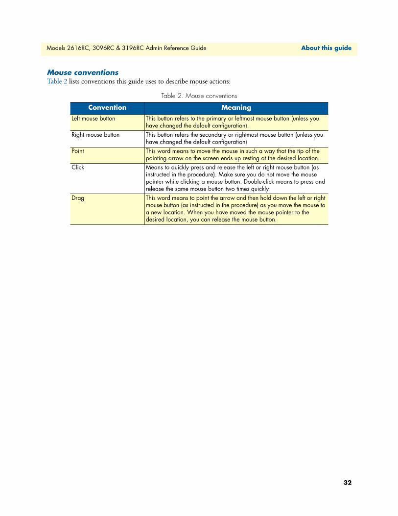
Models 2616RC, 3096RC & 3196RC Admin Reference Guide About this guide
Mouse conventionsTable 2 lists conventions this guide uses to describe mouse actions:
Table 2. Mouse conventions
Convention Meaning
Left mouse button This button refers to the primary or leftmost mouse button (unless you have changed the default configuration).
Right mouse button This button refers the secondary or rightmost mouse button (unless you have changed the default configuration)
Point This word means to move the mouse in such a way that the tip of the pointing arrow on the screen ends up resting at the desired location.
Click Means to quickly press and release the left or right mouse button (as instructed in the procedure). Make sure you do not move the mouse pointer while clicking a mouse button. Double-click means to press and release the same mouse button two times quickly
Drag This word means to point the arrow and then hold down the left or right mouse button (as instructed in the procedure) as you move the mouse to a new location. When you have moved the mouse pointer to the desired location, you can release the mouse button.
32

Chapter 1 Introduction
Chapter contentsIntroduction ..........................................................................................................................................................34Logging into the HTTP/HTML Web Management windows...............................................................................34HTTP/HTML and SNMP Object Format ...........................................................................................................35Saving HTTP/HTML Object Changes .................................................................................................................35
33
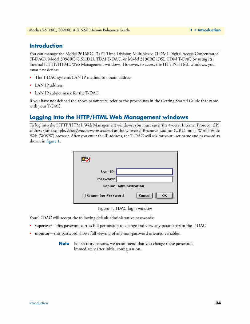
Models 2616RC, 3096RC & 3196RC Admin Reference Guide 1 • Introduction
IntroductionYou can manage the Model 2616RC T1/E1 Time Division Multiplexed (TDM) Digital Access Concentrator (T-DAC), Model 3096RC G.SHDSL TDM T-DAC, or Model 3196RC iDSL TDM T-DAC by using its internal HTTP/HTML Web Management windows. However, to access the HTTP/HTML windows, you must first define:
• The T-DAC system’s LAN IP method to obtain address
• LAN IP address
• LAN IP subnet mask for the T-DAC
If you have not defined the above parameters, refer to the procedures in the Getting Started Guide that came with your T-DAC
Logging into the HTTP/HTML Web Management windowsTo log into the HTTP/HTML Web Management windows, you must enter the 4-octet Internet Protocol (IP) address (for example, http://your.server.ip.address) as the Universal Resource Locator (URL) into a World-Wide Web (WWW) browser. After you enter the IP address, the T-DAC will ask for your user name and password as shown in figure 1.
Figure 1. T-DAC login window
Your T-DAC will accept the following default administrative passwords:
• superuser—this password carries full permission to change and view any parameters in the T-DAC
• monitor—this password allows full viewing of any non-password oriented variables.
Note For security reasons, we recommend that you change these passwords immediately after initial configuration.
Introduction 34
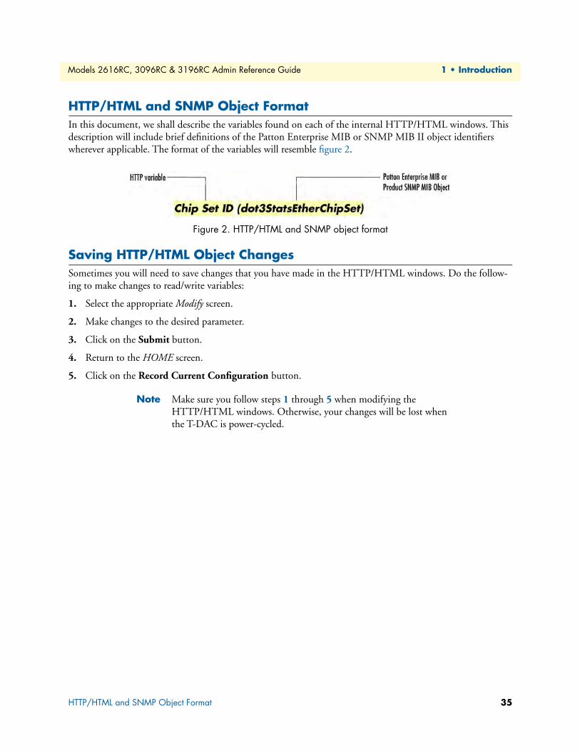
Models 2616RC, 3096RC & 3196RC Admin Reference Guide 1 • Introduction
HTTP/HTML and SNMP Object FormatIn this document, we shall describe the variables found on each of the internal HTTP/HTML windows. This description will include brief definitions of the Patton Enterprise MIB or SNMP MIB II object identifiers wherever applicable. The format of the variables will resemble figure 2.
Figure 2. HTTP/HTML and SNMP object format
Saving HTTP/HTML Object ChangesSometimes you will need to save changes that you have made in the HTTP/HTML windows. Do the follow-ing to make changes to read/write variables:
1. Select the appropriate Modify screen.
2. Make changes to the desired parameter.
3. Click on the Submit button.
4. Return to the HOME screen.
5. Click on the Record Current Configuration button.
Note Make sure you follow steps 1 through 5 when modifying the HTTP/HTML windows. Otherwise, your changes will be lost when the T-DAC is power-cycled.
HTTP/HTML and SNMP Object Format 35

Chapter 2 Home
Chapter contentsIntroduction ..........................................................................................................................................................37Product information box .......................................................................................................................................40Operating status variables ......................................................................................................................................41
Number of T1/E1 Ports (boxEgressCount) .....................................................................................................41% CPU Idle (boxIdleTime) ............................................................................................................................41Running Since Last Boot (sysUpTime) ...........................................................................................................41Chassis Address (cPCIShelfAddr) ....................................................................................................................41Slot Address (cPCISlotID) ..............................................................................................................................41Current Card State (alarmBoxState) ................................................................................................................42Total Card Alarms (alarmTotal) ......................................................................................................................42
Operator Actions ...................................................................................................................................................42Record Current Configuration (storeConfig(1)) .............................................................................................42Hard Reset (hardReset(2)) ..............................................................................................................................42Set Factory Default Configuration (forceDefaultConfig(3)) ............................................................................43
36
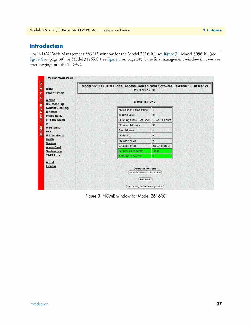
Models 2616RC, 3096RC & 3196RC Admin Reference Guide 2 • Home
IntroductionThe T-DAC Web Management HOME window for the Model 2616RC (see figure 3), Model 3096RC (see figure 4 on page 38), or Model 3196RC (see figure 5 on page 38) is the first management window that you see after logging into the T-DAC.
Figure 3. HOME window for Model 2616RC
Introduction 37
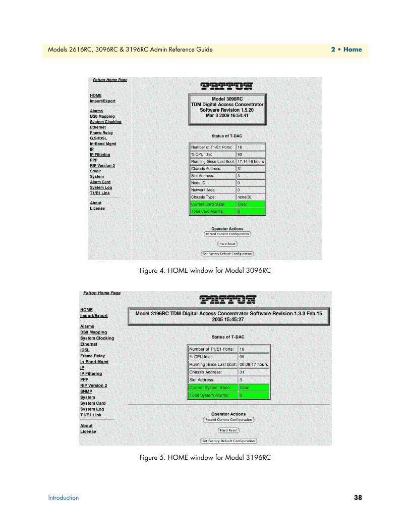
Models 2616RC, 3096RC & 3196RC Admin Reference Guide 2 • Home
Figure 4. HOME window for Model 3096RC
Figure 5. HOME window for Model 3196RC
Introduction 38
Models 2616RC, 3096RC & 3196RC Admin Reference Guide 2 • Home
The HOME window consists of sections that enable you to:
• View general product information about the T-DAC, such as the current software version (see section “Product information box” on page 40)
• View a summary of the system’s operating status that includes the following information:
– Number of egress ports on the rear blade
– Shelf address
– Slot ID
– Percent of idle CPU time
– Amount of time since the last time the system software was restarted (also referred to as booting)
– Current T-DAC (front blade/rear blade) alarm status, which displays the highest-level alarm currently detected in the T-DAC—listed as Major, Minor, or Clear (for none)
– Total alarms active in the T-DAC
See section “Operating status variables” on page 41 for more information.
• Initiate the following Operator Actions:
– Save any changes you have made to the T-DAC’s system configuration
– Perform a hard reset (cold restart) of the system without power-cycling the T-DAC. Reset all the T-DAC’s configurable parameters to their factory-default values.
See section “Operator Actions” on page 42 for more information.
The HOME window is divided into two panes: the Configuration Menu pane and the configuration/informa-tion pane (see figure 6). The Configuration Menu contains the links to the various T-DAC subsystem windows, while the configuration/information pane is where you can view status and other information, or make changes to the system configuration. Unlike the Configuration Menu pane, which looks the same no matter which subsystem window you may move to, the configuration/information pane contents will change as you move from one subsystem window to another.
Note Clicking on the HOME link in the Configuration Menu pane returns you to the HOME window from any other window.
Introduction 39
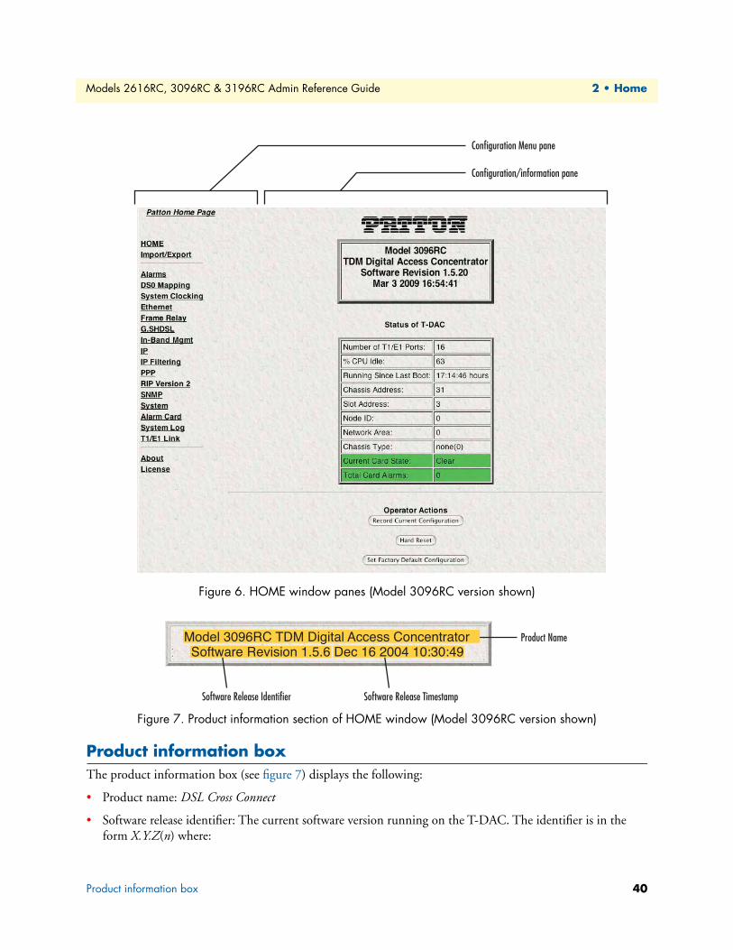
Models 2616RC, 3096RC & 3196RC Admin Reference Guide 2 • Home
Figure 6. HOME window panes (Model 3096RC version shown)
Figure 7. Product information section of HOME window (Model 3096RC version shown)
Product information boxThe product information box (see figure 7) displays the following:
• Product name: DSL Cross Connect
• Software release identifier: The current software version running on the T-DAC. The identifier is in the form X.Y.Z(n) where:
Configuration Menu pane
Configuration/information pane
Product Name
Software Release Identifier
Model 3096RC TDM Digital Access Concentrator
Software Release Timestamp
Software Revision 1.5.6 Dec 16 2004 10:30:49
Product information box 40
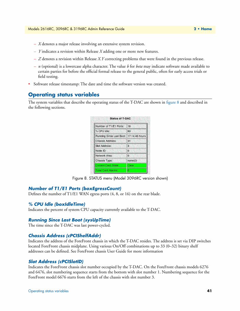
Models 2616RC, 3096RC & 3196RC Admin Reference Guide 2 • Home
– X denotes a major release involving an extensive system revision.
– Y indicates a revision within Release X adding one or more new features.
– Z denotes a revision within Release X.Y correcting problems that were found in the previous release.
– n (optional) is a lowercase alpha character. The value b for beta may indicate software made available to certain parties for before the official formal release to the general public, often for early access trials or field testing.
• Software release timestamp: The date and time the software version was created.
Operating status variablesThe system variables that describe the operating status of the T-DAC are shown in figure 8 and described in the following sections.
Figure 8. STATUS menu (Model 3096RC version shown)
Number of T1/E1 Ports (boxEgressCount)Defines the number of T1/E1 WAN egress ports (4, 8, or 16) on the rear blade.
% CPU Idle (boxIdleTime)Indicates the percent of system CPU capacity currently available to the T-DAC.
Running Since Last Boot (sysUpTime)The time since the T-DAC was last power-cycled.
Chassis Address (cPCIShelfAddr)Indicates the address of the ForeFront chassis in which the T-DAC resides. The address is set via DIP switches located ForeFront chassis midplane. Using various On/Off combinations up to 33 (0–32) binary shelf addresses can be defined. See ForeFront chassis User Guide for more information
Slot Address (cPCISlotID)Indicates the ForeFront chassis slot number occupied by the T-DAC. On the ForeFront chassis models 6276 and 6476, slot numbering sequence starts from the bottom with slot number 1. Numbering sequence for the ForeFront model 6676 starts from the left of the chassis with slot number 3.
Operating status variables 41

Models 2616RC, 3096RC & 3196RC Admin Reference Guide 2 • Home
Current Card State (alarmBoxState)The highest level alarm currently active on this T-DAC card—listed as Critical (red), Major (orange), Minor (yellow), or Clear (green)—no alarms present.
Total Card Alarms (alarmTotal)Total number of alarms currently active on this card.
Operator ActionsIn superuser mode you can initiate several operator actions (see figure 9) which will cause the T-DAC to oper-ate according to the descriptions in the following sections.
Figure 9. Operator Actions buttons
Record Current Configuration (storeConfig(1))Clicking the button labelled Record Current Configuration causes the T-DAC to save the current configura-tion in permanent Flash memory. In other words, configuration changes made in the subsystem web windows become permanent when you click Record Current Configuration.
Configuration changes in the T-DAC are made by clicking a button labelled Submit Query on any of the sub-system window. When you click Submit Query, the T-DAC stores the parameter values in volatile DRAM (dynamic RAM) only. Since the Submit Query changes take immediate effect, the administrator can test dif-ferent configuration parameters without needing to change the Flash configuration each time.
Without clicking on Record Current Configuration, all configuration changes will be lost if the power is recycled. After doing the Record Current Configuration save, the current configuration of the T-DAC will not be lost when The T-DAC is powered down.
Hard Reset (hardReset(2))This button causes the T-DAC to perform a cold restart. When you select Hard Reset, the T-DAC requests confirmation before executing the command, after which, the T-DAC will disconnect all current sessions, re-initialize the interfaces, and re-load configuration parameters from Flash memory.
The most important step after completing the configuration is to save it in permanent memory by clicking on Record Current Configuration.IMPORTANT
Operator Actions 42
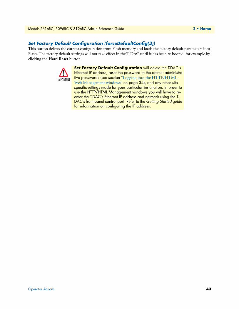
Models 2616RC, 3096RC & 3196RC Admin Reference Guide 2 • Home
Set Factory Default Configuration (forceDefaultConfig(3))This button deletes the current configuration from Flash memory and loads the factory default parameters into Flash. The factory default settings will not take effect in the T-DAC until it has been re-booted, for example by clicking the Hard Reset button.
Set Factory Default Configuration will delete the T-DAC’s Ethernet IP address, reset the password to the default administra-tive passwords (see section “Logging into the HTTP/HTML Web Management windows” on page 34), and any other site specific-settings made for your particular installation. In order to use the HTTP/HTML Management windows you will have to re-enter the T-DAC’s Ethernet IP address and netmask using the T-DAC’s front panel control port. Refer to the Getting Started guide for information on configuring the IP address.
IMPORTANT
Operator Actions 43
Chapter 3 Import/Export
Chapter contentsIntroduction ..........................................................................................................................................................45Export current Flash configuration ........................................................................................................................45Import Flash configuration from file......................................................................................................................47
44
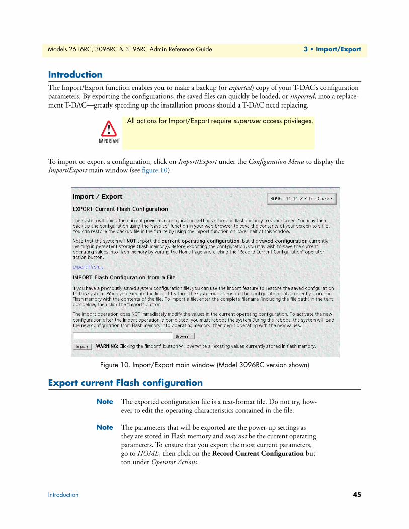
Models 2616RC, 3096RC & 3196RC Admin Reference Guide 3 • Import/Export
IntroductionThe Import/Export function enables you to make a backup (or exported) copy of your T-DAC’s configuration parameters. By exporting the configurations, the saved files can quickly be loaded, or imported, into a replace-ment T-DAC—greatly speeding up the installation process should a T-DAC need replacing.
To import or export a configuration, click on Import/Export under the Configuration Menu to display the Import/Export main window (see figure 10).
Figure 10. Import/Export main window (Model 3096RC version shown)
Export current Flash configuration
Note The exported configuration file is a text-format file. Do not try, how-ever to edit the operating characteristics contained in the file.
Note The parameters that will be exported are the power-up settings as they are stored in Flash memory and may not be the current operating parameters. To ensure that you export the most current parameters, go to HOME, then click on the Record Current Configuration but-ton under Operator Actions.
All actions for Import/Export require superuser access privileges.
IMPORTANT
Introduction 45
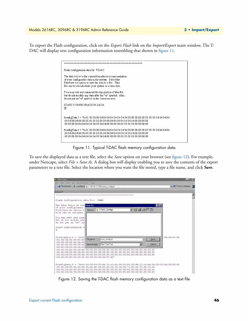
Models 2616RC, 3096RC & 3196RC Admin Reference Guide 3 • Import/Export
To export the Flash configuration, click on the Export Flash link on the Import/Export main window. The T-DAC will display text configuration information resembling that shown in figure 11.
Figure 11. Typical T-DAC flash memory configuration data
To save the displayed data as a text file, select the Save option on your browser (see figure 12). For example, under Netscape, select File > Save As. A dialog box will display enabling you to save the contents of the export parameters to a text file. Select the location where you want the file stored, type a file name, and click Save.
Figure 12. Saving the T-DAC flash memory configuration data as a text file
Export current Flash configuration 46
Models 2616RC, 3096RC & 3196RC Admin Reference Guide 3 • Import/Export
Import Flash configuration from fileTo import a configuration file into the T-DAC, type the complete path and filename for the configuration file you wish to load or click on the Browse… button to select the desired file, then click on the Submit Query button (see figure 10 on page 45).
Upon successfully importing the file, the T-DAC will display Configuration Load Complete, indicating that the new operating parameters have been loaded into Flash memory.
Click on HOME under the Configuration Menu, then click on the Hard Reset button under Operator Actions.
Note Do not select Record Current Configuration after importing config-uration parameters.
Import Flash configuration from file 47
Chapter 4 Alarms
Chapter contentsIntroduction ..........................................................................................................................................................49Alarm System Overview window ...........................................................................................................................49Alarms management windows ...............................................................................................................................52
Alarm System Configuration window .............................................................................................................52Alarm Syslog Priority (syslogAlarmPriority) ..............................................................................................53Board Temperature Threshold (boxAlarmTemperature) ...........................................................................53Alarm Trap Manager 1 through 4 (alarmTrapIp0–alarmTrapIp3) ............................................................54
Alarm Severity Configuration .........................................................................................................................54
48

Models 2616RC, 3096RC & 3196RC Admin Reference Guide 4 • Alarms
IntroductionThe T-DAC provides alarm facilities that monitor the operating status of the T-DAC’s power supply, 3096RC G.SHDSL and T1/E1 ports, 3196RC iDSL and T1/E1 ports, and 2616RC T1/E1 ports, and ambient temper-ature. The T-DAC provides three alarm signaling methods to indicate that an alarm condition has been detected:
• Visual indication—via the T-DAC front panel ALARM status LED and rear blade ALARM status LED indicators
• Operator console indication—via the T-DAC management windows
• External alarms management host indication—delivered via SNMP traps or Syslog messages that the T-DAC can send to an external alarms management host
By default, all T-DAC alarms are set to display as major (orange) events, but you can use the Alarm Systems management windows to customize them, assigning a higher or lower level of severity to each item as desired. Your choices are critical (red), major (orange), minor (yellow), informational (blue), or ignore (no color).
Alarm System Overview windowThe Alarm System Overview window (see figure 13) and related windows enable you to manage the T-DAC’s alarm system. Click on the Alarms hyperlink in the T-DAC’s Configuration Menu to display the Alarm System Overview window.
Note From the Alarm System Overview window the system administrator can force the T-DAC to generate alarms for testing purposes as well as clear selected alarms.
Introduction 49

Models 2616RC, 3096RC & 3196RC Admin Reference Guide 4 • Alarms
Figure 13. Alarm System Overview window (Model 3096RC version shown)
The T-DAC uses three methods to indicate an alarm condition:
• Front panel LED and rear blade indications—The front panel ALARM LED and rear blade ALARM LED uses the following three states to indicate the presence and severity of an alarm:
- Off—No alarm is active
- Solid—Minor alarm
- Flashing—Major alarm
Note The T-DAC’s factory-default configuration is to consider all alarms to be major (orange) ones, so unless you customize the alarms severity lev-els (see section “Alarm Severity Configuration” on page 54), any alarm that occurs will cause the ALARM LED to flash, indicating a major alarm—the LED will never indicate a minor alarm.
Note If both power supplies are functioning normally, the POWER LED will display a solid light, but if one or more power supplies fail, the POWER LED will flash.
Alarm System Overview window 50
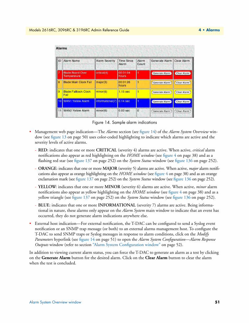
Models 2616RC, 3096RC & 3196RC Admin Reference Guide 4 • Alarms
Figure 14. Sample alarm indications
• Management web page indication—The Alarms section (see figure 14) of the Alarm System Overview win-dow (see figure 13 on page 50) uses color-coded highlighting to indicate which alarms are active and the severity levels of active alarms.
- RED: indicates that one or more CRITICAL (severity 4) alarms are active. When active, critical alarm notifications also appear as red highlighting on the HOME window (see figure 4 on page 38) and as a flashing red star (see figure 137 on page 252) on the System Status window (see figure 136 on page 252).
- ORANGE: indicates that one or more MAJOR (severity 5) alarms are active. When active, major alarm notifi-cations also appear as orange highlighting on the HOME window (see figure 4 on page 38) and as an orange exclamation mark (see figure 137 on page 252) on the System Status window (see figure 136 on page 252).
- YELLOW: indicates that one or more MINOR (severity 6) alarms are active. When active, minor alarm notifications also appear as yellow highlighting on the HOME window (see figure 4 on page 38) and as a yellow triangle (see figure 137 on page 252) on the System Status window (see figure 136 on page 252).
- BLUE: indicates that one or more INFORMATIONAL (severity 7) alarms are active. Being informa-tional in nature, these alarms only appear on the Alarm System main window to indicate that an event has occurred, they do not generate alarm indications anywhere else.
• External host indication—For external notification, the T-DAC can be configured to send a Syslog event notification or an SNMP trap message (or both) to an external alarms management host. To configure the T-DAC to send SNMP traps or Syslog messages in response to alarm conditions, click on the Modify Parameters hyperlink (see figure 14 on page 51) to open the Alarm System Configuration—Alarm Response Outputs window (refer to section “Alarm System Configuration window” on page 52).
In addition to viewing current alarm status, you can force the T-DAC to generate an alarm as a test by clicking on the Generate Alarm button for the desired alarm. Click on the Clear Alarm button to clear the alarm when the test is concluded.
Alarm System Overview window 51
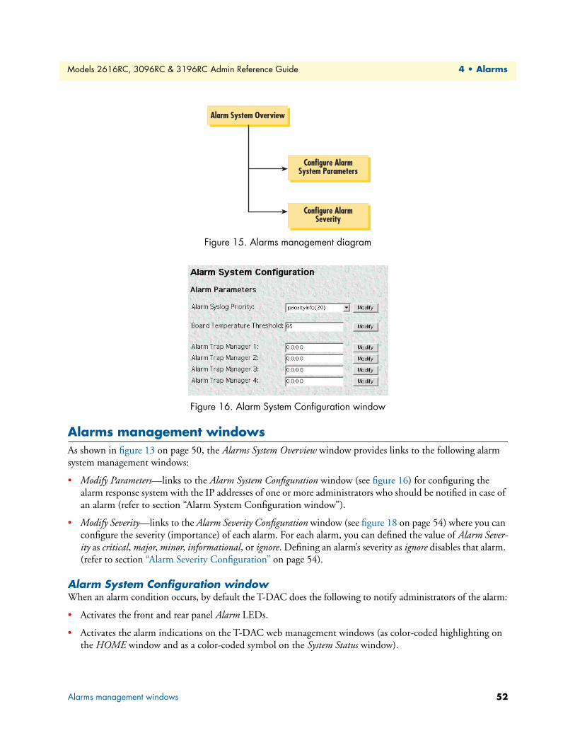
Models 2616RC, 3096RC & 3196RC Admin Reference Guide 4 • Alarms
Figure 15. Alarms management diagram
Figure 16. Alarm System Configuration window
Alarms management windowsAs shown in figure 13 on page 50, the Alarms System Overview window provides links to the following alarm system management windows:
• Modify Parameters—links to the Alarm System Configuration window (see figure 16) for configuring the alarm response system with the IP addresses of one or more administrators who should be notified in case of an alarm (refer to section “Alarm System Configuration window”).
• Modify Severity—links to the Alarm Severity Configuration window (see figure 18 on page 54) where you can configure the severity (importance) of each alarm. For each alarm, you can defined the value of Alarm Sever-ity as critical, major, minor, informational, or ignore. Defining an alarm’s severity as ignore disables that alarm. (refer to section “Alarm Severity Configuration” on page 54).
Alarm System Configuration windowWhen an alarm condition occurs, by default the T-DAC does the following to notify administrators of the alarm:
• Activates the front and rear panel Alarm LEDs.
• Activates the alarm indications on the T-DAC web management windows (as color-coded highlighting on the HOME window and as a color-coded symbol on the System Status window).
Alarm System Overview
Configure AlarmSystem Parameters
Configure AlarmSeverity
Alarms management windows 52
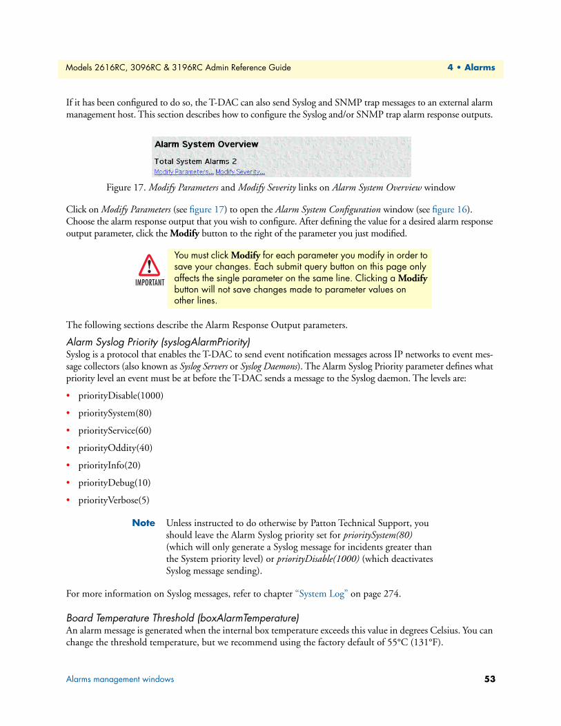
Models 2616RC, 3096RC & 3196RC Admin Reference Guide 4 • Alarms
If it has been configured to do so, the T-DAC can also send Syslog and SNMP trap messages to an external alarm management host. This section describes how to configure the Syslog and/or SNMP trap alarm response outputs.
Figure 17. Modify Parameters and Modify Severity links on Alarm System Overview window
Click on Modify Parameters (see figure 17) to open the Alarm System Configuration window (see figure 16). Choose the alarm response output that you wish to configure. After defining the value for a desired alarm response output parameter, click the Modify button to the right of the parameter you just modified.
The following sections describe the Alarm Response Output parameters.
Alarm Syslog Priority (syslogAlarmPriority)Syslog is a protocol that enables the T-DAC to send event notification messages across IP networks to event mes-sage collectors (also known as Syslog Servers or Syslog Daemons). The Alarm Syslog Priority parameter defines what priority level an event must be at before the T-DAC sends a message to the Syslog daemon. The levels are:
• priorityDisable(1000)
• prioritySystem(80)
• priorityService(60)
• priorityOddity(40)
• priorityInfo(20)
• priorityDebug(10)
• priorityVerbose(5)
Note Unless instructed to do otherwise by Patton Technical Support, you should leave the Alarm Syslog priority set for prioritySystem(80) (which will only generate a Syslog message for incidents greater than the System priority level) or priorityDisable(1000) (which deactivates Syslog message sending).
For more information on Syslog messages, refer to chapter “System Log” on page 274.
Board Temperature Threshold (boxAlarmTemperature)An alarm message is generated when the internal box temperature exceeds this value in degrees Celsius. You can change the threshold temperature, but we recommend using the factory default of 55°C (131°F).
You must click Modify for each parameter you modify in order to save your changes. Each submit query button on this page only affects the single parameter on the same line. Clicking a Modify button will not save changes made to parameter values on other lines.
IMPORTANT
Alarms management windows 53

Models 2616RC, 3096RC & 3196RC Admin Reference Guide 4 • Alarms
Alarm Trap Manager 1 through 4 (alarmTrapIp0–alarmTrapIp3)Simple Network Management Protocol (SNMP) trap daemons are a tool for managing TCP/IP networks, they are a simple method of alerting a management host of a problem with a device or application. The Alarm Trap Manager parameter is the IP address of a host running the SNMP trap daemon that will be receiving messages sent from the T-DAC. Upon the occurrence of an alarm, the T-DAC sends an SNMP trap message to the host system (or a management station) defined by this parameter.
Alarm Severity ConfigurationThis section describes configuring alarm severity levels. Clicking on Modify Severity (see figure 13 on page 50) displays the Alarm Severity Configuration window (see figure 18) listing of T-DAC alarms. From this window you can assign the severity for each alarm (critical, major, minor, informational, or ignore).
Figure 18. Alarm Severity Configuration window
Note The T-DAC’s factory-default configuration is to consider all alarms to be major (orange) ones, unless you customize the alarm’s severity levels.
The alarms can be independently configured to generate alarm messages. Each alarm item can be set for one of the following severity levels:
critical(4)—When active, critical alarm notifications appear as red highlighting on the HOME window (see figure 4 on page 38) and as a flashing red star (see figure 137 on page 252) on the System Status window (see figure 136 on page 252).
major(5)—When active, major alarm notifications appear as orange highlighting on the HOME window (see figure 4 on page 38) and as an orange exclamation mark (see figure 137 on page 252) on the System Status win-dow (see figure 136 on page 252).
• minor(6)—When active, minor alarm notifications appear as yellow highlighting on the HOME window (see figure 4 on page 38) and as a yellow triangle (see figure 137 on page 252) on the System Status window (see figure 136 on page 252).
The Alarm Trap Manager requires that an IP address be entered. If you do not want the T-DAC to send SNMP trap messages, entering an address of 0.0.0.0 disables SNMP trap message sending.IMPORTANT
Alarms management windows 54
Models 2616RC, 3096RC & 3196RC Admin Reference Guide 4 • Alarms
• informational(7)—Being informational in nature, these alarms only appear as blue highlighting on the Alarm System main window to indicate that an event has occurred, they do not generate alarm indications anywhere else.
• ignore(0)—The T-DAC will not generate an alarm.
To configure the severity for a selected alarm, click on the drop-down menu for the that alarm, select the desired severity value, then click on Modify to implement the change.
You can disable an alarm (as appropriate for your application) by defining its severity as ignore.
IMPORTANT
Alarms management windows 55

Chapter 5 DS0 Mapping
Chapter contentsIntroduction ..........................................................................................................................................................58DS0 Mapping Overview main window..................................................................................................................59DS0 mapping and in-band management ...............................................................................................................60Non-blocking system constraints with in-band management .................................................................................60System design considerations and guidelines..........................................................................................................60DS0 Fallback Configuration window ....................................................................................................................61
Fallback Help button ......................................................................................................................................61Watch the following ports for a failure state ....................................................................................................62
Watch Port Type (daxWatchTypegshDSL) ...............................................................................................62Watch Port Number (daxWatchPortgshDSL) ...........................................................................................62Watch Port Slots (daxWatchSlot) ..............................................................................................................62
Slot Numbering Examples................................................................................................................... 63In case of failure, switch to the following port .................................................................................................63
Fallback Port Type (daxFallbackTypegshDSL) ..........................................................................................64Fallback Port Number (daxFallbackPortGsDS) .........................................................................................64Fallback Port Slots (daxFallbackSlot) .........................................................................................................64Fallback Port Type fromH110(0) (daxFallbackTypegshDSLH110) ..........................................................64Fallback Port Number (daxFallbackPortgshDSLH11) ...............................................................................64Fallback Port Slots (daxFallbackSlotH110) ...............................................................................................65
Port Fallback Table .........................................................................................................................................65Fallback Mapping ID ................................................................................................................................65Recovery Type (daxFallbackRecovery) .......................................................................................................65
DS0 Fallback ID (DAX Fallback ID) window ................................................................................................65Viewing the DS0 Fallback ID window ............................................................................................................65
Deleting a Fallback Mapping ..........................................................................................................................66Force Recovery button ....................................................................................................................................66
Display Option parameter .....................................................................................................................................66Mapping Help.......................................................................................................................................................67Configuring static connections using the long form...............................................................................................67
Device Type A (daxDeviceTypeTogshDSL) ....................................................................................................67Device Type B (daxDeviceTypeFromgshDSL) (daxDeviceTypeRxgshDSL) ...................................................68Device Number A (daxDeviceNumberTogshDSL) and Device Number B (daxDeviceNumberFromgshDSL) (daxDeviceNumberRxgshDSL) .................................................................68Device Slots A and B (daxDeviceSlotTo) (daxDeviceSlotFrom) ......................................................................69
Slot Numbering Examples .........................................................................................................................69Defining DS0 mappings using the command line interface (CLI) .........................................................................70
Slot Numbering Examples ..............................................................................................................................71Saving a DS0 mapping definition ..........................................................................................................................72Defined Mappings Table (Static Connections) ......................................................................................................72
56
Models 2616RC, 3096RC & 3196RC Admin Reference Guide 5 • DS0 Mapping
ID (daxConnectionID) ...................................................................................................................................72Fallback ..........................................................................................................................................................72Type A ............................................................................................................................................................73Port A .............................................................................................................................................................73Slots A ............................................................................................................................................................73Type B ............................................................................................................................................................73Port B .............................................................................................................................................................73Slots B ............................................................................................................................................................73
DS0 Connection ID (DAX Connection ID) window............................................................................................73Viewing the DS0 Connection ID window ......................................................................................................73Deleting a DS0 Mapping ................................................................................................................................74
57

Models 2616RC, 3096RC & 3196RC Admin Reference Guide 5 • DS0 Mapping
IntroductionTo route traffic from one device connected to the T-DAC to another device (also connected to the T-DAC) you must define a DS0 mapping (also called an internal connection or cross-connection). An internal cross-connection carries traffic between the two external devices via the T-DAC. The external devices can be (but are not limited to) a T1/E1 NTU, a G.SHDSL customer premise equipment (CPE) modem, or another blade in the same CPCI chassis in which the T-DAC is installed.
The T-DAC’s DS0 Mapping Overview window (see figure 19) provides the means for managing (mapping) internal connections.
Note DS0 Mapping device and port options for the T-DAC family of products are as follows:
• 3096RC—G.SHDSL ports (16), T1/E1 ports (up to 16), and H.110 ports (32)
• 3196RC— iDSL ports (16), T1/E1 ports (up to 16), and H.110 ports (32)
• 2616RC—T1/E1 ports (16), H.110 ports (32)
Because of the similarities between TDACs, DS0 and fallback map-ping examples presented in this chapter are generic and meant to be used only as a guide—apply DS0 mapping to your particular T-DAC as appropriate.
Figure 19. DS0 Mapping Overview window
External devices can connect to the T-DAC via a T1/E1 WAN port, a DSL port, or an H.110 port. (A device will connect to an H.110 port via the T-DAC’s interface to the H.110 bus in the cPCI chassis midplane). Each DS0 mapping defines a one-to-one connection between a selected number of timeslots on one port and a cor-responding number of timeslots on a different port. You can use the DS0 Mapping management web page to define these DS0 mappings (internal connections) and to view previously defined mappings.
Introduction 58
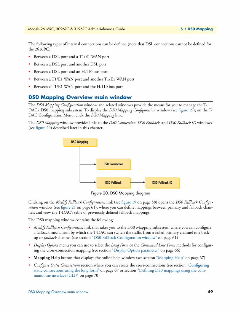
Models 2616RC, 3096RC & 3196RC Admin Reference Guide 5 • DS0 Mapping
The following types of internal connections can be defined (note that DSL connections cannot be defined for the 2616RC:
• Between a DSL port and a T1/E1 WAN port
• Between a DSL port and another DSL port
• Between a DSL port and an H.110 bus port
• Between a T1/E1 WAN port and another T1/E1 WAN port
• Between a T1/E1 WAN port and the H.110 bus port
DS0 Mapping Overview main windowThe DS0 Mapping Configuration window and related windows provide the means for you to manage the T-DAC’s DS0 mapping subsystem. To display the DS0 Mapping Configuration window (see figure 19), on the T-DAC Configuration Menu, click the DS0 Mapping link.
The DS0 Mapping window provides links to the DS0 Connection, DS0 Fallback, and DS0 Fallback ID windows (see figure 20) described later in this chapter.
Figure 20. DS0 Mapping diagram
Clicking on the Modify Fallback Configuration link (see figure 19 on page 58) opens the DS0 Fallback Configu-ration window (see figure 21 on page 61), where you can define mappings between primary and fallback chan-nels and view the T-DAC’s table of previously defined fallback mappings.
The DS0 mapping window contains the following:
• Modify Fallback Configuration link that takes you to the DS0 Mapping subsystem where you can configure a fallback mechanism by which the T-DAC can switch the traffic from a failed primary channel to a back-up or fallback channel (see section “DS0 Fallback Configuration window” on page 61)
• Display Option menu you can use to select the Long Form or the Command Line Form methods for configur-ing the cross-connection mapping (see section “Display Option parameter” on page 66)
• Mapping Help button that displays the online help window (see section “Mapping Help” on page 67)
• Configure Static Connections section where you can create the cross-connections (see section “Configuring static connections using the long form” on page 67 or section “Defining DS0 mappings using the com-mand line interface (CLI)” on page 70)
DS0 Mapping
DS0 Connection
DS0 Fallback DS0 Fallback ID
DS0 Mapping Overview main window 59
Models 2616RC, 3096RC & 3196RC Admin Reference Guide 5 • DS0 Mapping
• Static Connection section where you can view the previously defined DS0 mappings (cross-connections) in the T-DAC (see section “Defined Mappings Table (Static Connections)” on page 72)
DS0 mapping and in-band managementWhen in-band management (see chapter 11, “In-band management” on page 149) is configured, some of the DS0’s bandwidth is no longer available for standard DS0 mapping. If a Model 6511RC Matrix Switch is not in the ForeFront chassis, in-band management provides access to the management service in all cards installed in the ForeFront chassis.
Non-blocking system constraints with in-band managementEach 3096RC & 3196RC T-DAC module provides a pool of 4096 simplex DS0s for DS0 mapping to other ForeFront modules. These DS0s are for interconnecting ports between modules via the ForeFront’s midplane. Each module-to-module mapping requires a minimum of two simplex DS0s, one for transmitting and one for receiving. The 3096RC and 3196RC T-DAC’s support totally non-blocking, any-to-any mapping using all 4096 DS0 simplex channels.
Configuring Chassis Management Channels for in-band management is a special case. The T-DAC automati-cally allocates half of its DS0 pool (2048 DS0s) to in-band management. This allocation reduces the T-DAC’s pool of DS0s for DS0 inter-module mapping from 4096 to 2048 simplex DS0s. However, with proper system design, the allocation of 2048 DS0s is rarely limiting.
If one or more Chassis Management Channels have been configured, the T-DAC’s DS0 mapping subsystem of 4096 simplex DS0s is split into two pools (each with 2048 DS0s): one pool for the Chassis Management Channel and the other for mapping to other ForeFront modules (see the note below for how many DS0s are used in a Chassis Management Channel). You may select from any of the unused DS0 ports and time slots. (“Unused” means a DS0 port and time slot that have not specifically been assigned a DS0 mapping to another card or a CMC.
Upon deleting the last Chassis Management Channel, the T-DAC de-allocates the 2048 DS0s reserved for in-band management, returning them to the pool so all 4096 DS0s are again available for mappings to other modules.
Note The T-DAC supports a maximum of 10 full-duplex Chassis Manage-ment Channels. Each Chassis Management Channel utilizes 2 DS0s, one for transmitting and one for receiving. As a result, 10 Chassis Man-agement Channels utilize only 20 DS0s from the 2048 DS0s allocated to the function.
System design considerations and guidelinesIn order to maximize the T-DAC’s throughput while using the Chassis Management Channel feature, remem-ber the following points when defining standard (non-management) DS0 mappings. When Chassis Manage-ment Channels are implemented, the following T-DAC mappings utilize DS0s from the pool of 2048 DS0s available for mappings to other modules:
• Between any T-DAC G.SHDSL port (Model 3096RC) or iDSL port (Model 3196RC) and any DS0 used to map to another module
• Between any T-DAC T1/E1 port any used to map to another module.
DS0 mapping and in-band management 60

Models 2616RC, 3096RC & 3196RC Admin Reference Guide 5 • DS0 Mapping
When Chassis Management Channel is implemented, the following guideline will assist in achieving maxi-mum user-data throughput through the Model 3096RC T-DAC:
• Total number of simplex DS0s used to map G.SHDSL and/or T1/E1 ports to and from another module must not exceed 2048.
DS0 Fallback Configuration windowThe DS0 Mapping subsystem provides a fallback mechanism by which the T-DAC can switch traffic from a failed primary channel (channel is defined as a group of time slots on a given port) to a previously defined fall-back channel. Once you have defined a fallback mapping, the T-DAC will monitor the primary channel for failure and, should the primary channel fail, the fallback channel will switch in (take over the traffic) for the primary channel. Once it has switched in, the fallback channel will carry all traffic the primary channel previ-ously carried.
Clicking on the DACS Fallback System link (see figure 19 on page 58) opens the DS0 Fallback Configuration window (see figure 21), where you can define mappings between primary and fallback channels and view the T-DAC’s table of previously defined fallback mappings.
Figure 21. DACS Fallback Configuration window
Fallback Help buttonWhen you click the Fallback Help button, the T-DAC will display the Fallback Mapping Help page in a new window (see figure 22). The Fallback Mapping Help page provides a procedural outline and a summarized description of the parameters for defining a fallback mapping.
DS0 Fallback Configuration window 61

Models 2616RC, 3096RC & 3196RC Admin Reference Guide 5 • DS0 Mapping
Figure 22. Fallback Mapping help window
Watch the following ports for a failure stateThe Watch the following ports for a failure state section parameters (see figure 19 on page 58) define the primary channel in a fallback mapping.
Watch Port Type (daxWatchTypegshDSL)The port type for the primary channel port. Select one of the following values from the drop-down menu.
• none(0)
• t1-e1(1) (all models)
• gshDSL(4) (Model 3096RC) or iDSL(2) (Model 3196RC)
Watch Port Number (daxWatchPortgshDSL)The Watch Port Number corresponds to one of the T-DAC’s 16 G.SHDSL (Model 3096RC) or iDSL (Model 3196RC) ports, or one of the 4, 8, 12, or 16 T1/E1 WAN ports. Within each port type, port numbers begin with 1 and end with the total number of ports of that type (e.g. 16 for G.SHDSL). As an example, to define a primary channel using the T-DAC third WAN port, you would select Port 3 as the value for Watch Port Number.
Watch Port Slots (daxWatchSlot)The Watch Port Slots parameters define which time slots will comprise the primary channel for the fallback mapping. Each time slot provides a 64 kbps data communications channel. Such a 64 kbps channel is also known as a DS0. The following time slots are available:
• G.SHDSL (Model 3096RC) modem port: 36 time slots (DS0s) numbered 1 through 36, or iDSL (Model 3196RC) modem port: 3 DS0s at 144 kbps
• T1 WAN port: 24 time slots (DS0s), numbered 1 through 24
• E1 WAN port: 32 time slots (DS0s), numbered 1 through 32
• H.110 streams can support up to 128 slots.
Note You must define the same number of time slots for the primary and fallback channels. In other words, the number of time slots defined for Watch Port Slots must equal the number of time slots defined for Fallback Port Slots.
DS0 Fallback Configuration window 62

Models 2616RC, 3096RC & 3196RC Admin Reference Guide 5 • DS0 Mapping
To define value for the time slots parameter, you will enter a text string specifying which time slot numbers will be used for the channel. You must enter the text string using a prescribed notation comprised of the following elements:
• Numerals—Use numerals (1, 2, 3, 4, 5, 6, 7, 8, 9) to represent time slot numbers
• Comma—Use the comma (,) to separate non-contiguous timeslots. For example, the string 1,7,15 repre-sents three timeslots numbered 1, 7 and 15.
Note You may also use the comma to separate contiguous timeslots. How-ever, since it is inefficient and may be confusing, doing so is not rec-ommended.
• Dash—Use the dash ( - ) to represent a series of contiguous timeslots. For example, the string 1–32 repre-sents all timeslots between 1 and 32 inclusive (i.e. time slot 1, time slot 32 and all time slots in between).
Slot Numbering Examples. For example, to define a channel comprising timeslots 1, 2, 5, 6, 7, and 15, either of the following entries would be valid.
• 1,2,5-7,15
• 1-2,5-7,15
Note Do not insert spaces after the commas.
Although the first string above is valid syntax, the second string is easier to read, and more clearly shows what is going on.
In case of failure, switch to the following portThe In case of failure, switch to the following port section parameters (see figure 19 on page 58) define the alter-nate (backup) channel in a fallback mapping. If the fallback channel comprises a T1/E1 or DSL port (i.e. not an H.110 connection), you must define the first fallback port only, (i.e. the first three parameters) as shown in table 3. When the fallback channel comprises an H.110 connection, you must define both fallback ports (i.e. all six parameters) as shown in table 3.
The first set of fallback port parameters (Fallback Port Type, Fallback Port Number, and Fallback Port Slots) defines the transmit connection to the H.100 bus from the T-DAC. The second set of fallback port parameters defines the receive connection from the H.110 bus to the T-DAC. The following sections describe the fallback channel parameters.
Table 3. Fallback port configuration
T1/E1 or DSL port H.110 port
Fallback Port Type Configure ConfigureFallback Port Number Configure ConfigureFallback Port Slots Configure ConfigureFallback Port Type ConfigureFallback Port Number ConfigureFallback Port Slots Configure
DS0 Fallback Configuration window 63

Models 2616RC, 3096RC & 3196RC Admin Reference Guide 5 • DS0 Mapping
Fallback Port Type (daxFallbackTypegshDSL)This parameter defines the port type for the fallback channel. Select one of the following values from the drop-down menu:
• none(0)
• t1-e1(1)
• gshDSL(4) (Model 3096RC) or iDSL(2) (Model 3196RC)
• toH110(5)
Note Selecting toH110(5) defines only the fallback transmit channel to the H.110 bus. You must also define the fallback receive channel from the H.110 bus by selecting fromH110(6) as the value of the second Fallback Port Type parameter (see section “Fallback Port Type fromH110(0) (daxFallbackTypegshDSLH110)” on page 64).
Fallback Port Number (daxFallbackPortGsDS)The Fallback Port Number corresponds to one of the T-DAC’s 16 G.SHDSL or iDSL ports, one of the 4, 8, 12, or 16 T1/E1 WAN ports, or one of the 32 H.110 ports. Within each port type, port numbers begin with 1 and end with the total number of ports of that type (for example, 16 for G.SHDSL, 32 for H.110). As an example, to define a fallback transmit channel using the T-DAC third H.110 port, you would select Port 3(3) as the value for Fallback Port Number.
Fallback Port Slots (daxFallbackSlot)The Fallback Port Slots parameters define which time slots will comprise the alternate (fallback) channel for the fallback mapping. Use the same notation as for Watch Port Slots, as described in section “Watch Port Slots (daxWatchSlot)” on page 62.
Fallback Port Type fromH110(0) (daxFallbackTypegshDSLH110)This parameter defines the port type for fallback receive channel from the H.110 bus to the T-DAC. Select one of the following values from the drop-down menu.
• none(0)
• fromH110(6)
Note Selecting fromH110(6) defines only the fallback receive channel from the H.110 bus. In order to fully define an H.110 fallback channel, you must first define the transmit channel to the H.100 bus by select-ing toH110(5) as the value of the first Fallback Port Type parameter (see section “Fallback Port Type (daxFallbackTypegshDSL)” on page 64).
Fallback Port Number (daxFallbackPortgshDSLH11)The Fallback Port Number corresponds to one of the T-DAC’s 32 H.110 ports. For example, to define a fall-back receive channel using the T-DAC’s fourth H.110 port, you would select port 4(4) as the value of Fallback Port Number.
DS0 Fallback Configuration window 64

Models 2616RC, 3096RC & 3196RC Admin Reference Guide 5 • DS0 Mapping
Fallback Port Slots (daxFallbackSlotH110)This parameter defines which time slots will comprise the fallback receive channel from the H.110 bus to the T-DAC for the fallback mapping. Use the same notation as for Watch Port Slots (see section “Watch Port Slots (daxWatchSlot)” on page 62).
Port Fallback TableThe Port Fallback Table (see figure 21 on page 61) displays a list of all existing fallback mappings which a T-DAC operator has previously defined. Each row in the table displays a single fallback mapping, identified by an ID number.
Fallback Mapping IDClicking the fallback mapping ID hyperlink displays the DAX Fallback ID window, which you can use to delete the specified fallback mapping or change the value of the fallback Recovery Type parameter (see section “DS0 Fallback ID (DAX Fallback ID) window”)
The parameters comprising each fallback mapping are described in the paragraphs above, with one the excep-tion—Recovery Type (see section “Recovery Type (daxFallbackRecovery)”).
Recovery Type (daxFallbackRecovery)The Recovery Type parameter defines how the T-DAC will behave when the primary channel in a fallback mapping recovers (returns to normal operation) once the fallback channel has switched in. There are two options for the value of Recovery Type.
• userForceRecovery(0)—Default. When the primary channel port recovers and all failures are cleared, the T-DAC will continue to route traffic over the fallback channel until the T-DAC operator intervenes.
To force traffic back to the primary channel:
- On the DS0 Mapping page, in the Static Connections table, find the connection for which you wish to force recovery.
- On the right-most side of the row, click the Force Recovery button
• autoRecovery(1)—When the primary channel port recovers and all failures are cleared, the T-DAC will automatically switch back to the primary channel defined for the connection and resume routing all traffic for the connection over the primary channel.
DS0 Fallback ID (DAX Fallback ID) windowFor the selected fallback mapping the DS0 Fallback ID window provides the capability to:
• Delete an existing DS0 fallback mapping (backup connection)
• Change the value of the fallback Recovery Type parameter.
The page also displays all parameters which define the selected fallback mapping.
Viewing the DS0 Fallback ID windowTo view the DS0 Fallback ID window for a specific DS0 Fallback Mapping (backup connection):
1. On the DS0 Fallback page, under Port Fallback Table, find the Connection ID number for the fallback mapping you wish to view.
DS0 Fallback Configuration window 65
Models 2616RC, 3096RC & 3196RC Admin Reference Guide 5 • DS0 Mapping
2. Click the Connection ID number hyperlink to display the DS0 Fallback ID window for the selected con-nection ID.
Deleting a Fallback MappingTo delete the Fallback Mapping displayed on the DS0 Fallback ID window:
1. In the drop-down menu for the Connection Status parameter, ensure that the value delete(1) is selected.
2. Click the Submit Query button to delete the connection (DS0 mapping).
Force Recovery buttonWhen a fallback channel switches in for a primary channel, the T-DAC will display a force recovery button to the far right of the table, next to the entry for the failed connection. However, the button will only appear if the fallback connection is defined in Force Recovery mode. If the fallback connection is defined in Auto Recov-ery mode, the button will not appear.
Display Option parameterTo define DS0 mappings (connections), you can use either the Long Form or the Command Line Form. To choose the method you prefer, use the Display Option drop-down box (see figure 21 on page 61) to select one of the following parameter values:
• displayLongForm(0)—(Factory Default). Most people consider Long Form the easier method for defining DS0 mappings.The Long Form displays the DS0 Mapping page in the standard management window for-mat with drop-down boxes and text box fields. Use this format to define the DS0 Mapping parameters by selecting values from drop-down boxes and typing values in the text box fields. (Refer to section “Configur-ing static connections using the long form” on page 67 for information on using the Long Form to config-ure static connections.)
• displayCliForm(1)—Advanced users of the command line interface (CLI) method may consider CLI a faster and more convenient method than the Long Form. To use CLI to define DS0 mappings, select displayCliForm(1) and click on the Modify button. The DS0 Mapping page will refresh, displaying a single text box (in place of the drop-down boxes and text box parameter fields) into which you may enter CLI commands. (Refer to section “Defining DS0 mappings using the command line interface (CLI)” on page 70 for information on using the CLI to configure static connections.)
Display Option parameter 66

Models 2616RC, 3096RC & 3196RC Admin Reference Guide 5 • DS0 Mapping
Mapping HelpClicking on the Mapping Help button displays the DS0 Mapping Help window (see figure 20). The DS0 Map-ping Help page provides a convenient online tutorial on how to use the T-DAC’s web management pages to define DS0 mappings (cross-connections). The tutorial includes definitions for all configurable parameters on the DS0 Mapping web page. If you are using command line format to define DS0 connections, scroll down to the Command Line Format heading.
Figure 23. DACS Help Information window
Configuring static connections using the long formTo create a DS0 mapping (cross-connection) between external devices, you must define channels A and B.
External devices may include (but are not limited to) an NTU, a G.SHDSL CPE, or another blade installed in the same CPCI chassis as the T-DAC.
Figure 24. Configure Static Connections section of DS0 Mapping Configuration window
The drop-down menus in the Configure Static Connections section of the DS0 Mapping Configuration window (see figure 24) are organized into A and B channels. These channel names have been arbitrarily chosen and, as all data will be bi-directional, do not signify the direction that data will travel. In displayLongForm mode, you will use drop-down menus and text boxes to define the DS0 mapping parameters. The following parameters define each channel the mapped connection (see figure 24).
• Device type (Dev Type)
• Device number (Dev Num) (see page 68)
• Device slots (Dev Slots) (see page 69)
Device Type A (daxDeviceTypeTogshDSL)The Dev Type A menu defines the type of interface port the T-DAC will use for the A channel of this connection. The user has the option of selecting a T1/E1 device or a DSL device
Mapping Help 67
Models 2616RC, 3096RC & 3196RC Admin Reference Guide 5 • DS0 Mapping
Note Both channels of the connection can be T1/E1 or both sides can be G.SHDSL (Model 3096RC) or iDSL (Model 3196RC) or just the B channel could be configured (in the event you needed to create an H.110 loopback).
The options are:
• none(0)
• t1-e1(1)—T1/E1 WAN ports for connection to a T1/E1 WAN line
• gshDSL(4)—G.SHDSL ports for connection to a G.SHDSL modem (Model 3096RC) oriDSL(2)—iDSL ports for connection to an iDSL modem (Model 3196RC).
Device Type B (daxDeviceTypeFromgshDSL) (daxDeviceTypeRxgshDSL)The Dev Type B menu defines the type of interface port the T-DAC will use for the B channel of this connection. The user has the option of selecting a T1/E1 device, a DSL device, or the H.110 midplane (the H.110 selection can only be done from the B channel selection because it requires a To and From direction identifier.
Note On the DS0 Mapping window, under Device B, there are two rows of parameter fields for defining H.110 connections. When defining a T1/E1 or DSL connection, do not define the parameters in the second row (i.e. leave the menu set to none(0)). When defining an H.110 connec-tion, you must define values for all parameters in both rows.
Each connection to the H.110 bus consists of a pair of logical ports. The T-DAC transmits data to the H.110 bus using one logical port, and receives data from the H.110 bus on a different logical port. Under Device B, the DS0 Mapping page provides two rows of parameter fields for defining H.110 connections. When defining an H.110 connection, you must define values for all parameters in both rows. The parameters in the first row under Device B define the transmit port (to the H.110 bus) and parameters in the second row under Device B define the receive port (from the H.110 bus).
In the first row, the following options are available for Dev Type B:
• none(0)
• t1-e1(1)—T1/E1 WAN ports for connection to a T1/E1 WAN line
• gshDSL(4)—G.SHDSL ports for connection to a G.SHDSL modem (Model 3096RC) oriDSL(2)—iDSL ports for connection to an iDSL modem (Model 3196RC)
• toH110(5)—H.110 port for transmitting data to the H.110 bus via the CPCI chassis backplane.
In the second row, the following options are available for Dev Type B:
• none(0)
• fromH110(6)—H.110 port for receiving data from the H.110 bus via the CPCI chassis backplane.
Device Number A (daxDeviceNumberTogshDSL) and Device Number B (daxDeviceNumberFromgshDSL) (daxDeviceNumberRxgshDSL)The parameters labeled Dev Num A and Dev Num B define the ports the T-DAC will use for channel A and channel B. The Device Number will correspond to one of the T-DAC’s 16 G.SHDSL (Model 3096RC) or
Configuring static connections using the long form 68
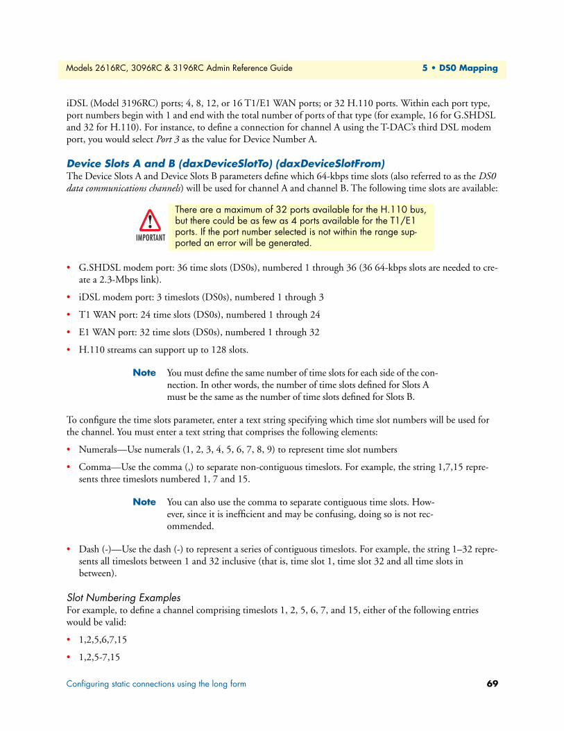
Models 2616RC, 3096RC & 3196RC Admin Reference Guide 5 • DS0 Mapping
iDSL (Model 3196RC) ports; 4, 8, 12, or 16 T1/E1 WAN ports; or 32 H.110 ports. Within each port type, port numbers begin with 1 and end with the total number of ports of that type (for example, 16 for G.SHDSL and 32 for H.110). For instance, to define a connection for channel A using the T-DAC’s third DSL modem port, you would select Port 3 as the value for Device Number A.
Device Slots A and B (daxDeviceSlotTo) (daxDeviceSlotFrom)The Device Slots A and Device Slots B parameters define which 64-kbps time slots (also referred to as the DS0 data communications channels) will be used for channel A and channel B. The following time slots are available:
• G.SHDSL modem port: 36 time slots (DS0s), numbered 1 through 36 (36 64-kbps slots are needed to cre-ate a 2.3-Mbps link).
• iDSL modem port: 3 timeslots (DS0s), numbered 1 through 3
• T1 WAN port: 24 time slots (DS0s), numbered 1 through 24
• E1 WAN port: 32 time slots (DS0s), numbered 1 through 32
• H.110 streams can support up to 128 slots.
Note You must define the same number of time slots for each side of the con-nection. In other words, the number of time slots defined for Slots A must be the same as the number of time slots defined for Slots B.
To configure the time slots parameter, enter a text string specifying which time slot numbers will be used for the channel. You must enter a text string that comprises the following elements:
• Numerals—Use numerals (1, 2, 3, 4, 5, 6, 7, 8, 9) to represent time slot numbers
• Comma—Use the comma (,) to separate non-contiguous timeslots. For example, the string 1,7,15 repre-sents three timeslots numbered 1, 7 and 15.
Note You can also use the comma to separate contiguous time slots. How-ever, since it is inefficient and may be confusing, doing so is not rec-ommended.
• Dash (-)—Use the dash (-) to represent a series of contiguous timeslots. For example, the string 1–32 repre-sents all timeslots between 1 and 32 inclusive (that is, time slot 1, time slot 32 and all time slots in between).
Slot Numbering ExamplesFor example, to define a channel comprising timeslots 1, 2, 5, 6, 7, and 15, either of the following entries would be valid:
• 1,2,5,6,7,15
• 1,2,5-7,15
There are a maximum of 32 ports available for the H.110 bus, but there could be as few as 4 ports available for the T1/E1 ports. If the port number selected is not within the range sup-ported an error will be generated.IMPORTANT
Configuring static connections using the long form 69

Models 2616RC, 3096RC & 3196RC Admin Reference Guide 5 • DS0 Mapping
Although the first string above is valid syntax, the second string is easier to read, and more clearly shows what is going on. The following strings are also valid syntax:
• 1-2,5,6,7,15
• 1-2,5,6-7,15
• 1-2,5-6,7,15
While the entries above would work, they are harder to grasp quickly than the first two examples. Beyond the cluttered appearance of these last three strings, they tend to obscure the part of reality they represent: the con-tiguous block of timeslots from 5-7.
After entering the parameters required to define the DS0 mapping, go to section “Saving a DS0 mapping definition” on page 72 for information on saving your cross-connection map to the T-DAC’s random access memory (RAM) in order to activate the connection.
Defining DS0 mappings using the command line interface (CLI)To define a new connection using CLI, you must enter text strings in the following format:
DeviceA:PortA:SlotsA/DeviceB:PortB:SlotsB
DeviceA and DeviceB define the type of interface the T-DAC will use for each channel of the connection. The following options are available:
• 1) t1-e1
• 2) gshDSL or iDSL ports
• 3) toH110
• 4) from H110
PortA and PortB define which one of its 16 G.SHDSL or iDSL ports; 4, 8, 12, or 16 WAN ports; or 32 H.110 ports the T-DAC will use for each channel of the connection. The value must be a number from 1 to 16 inclusive.
The Device Slots A and Device Slots B parameters define which 64-kbps time slots (also referred to as the DS0 data communications channels) will be used for channel A and channel B. The following time slots are available:
• G.SHDSL or iDSL modem port:
- G.SHDSL modem port: 36 time slots (DS0s), numbered 1 through 36 (36 64-kbps slots are needed to create a 2.3-Mbps link)
- iDSL modem port: 3 timeslots (DS0s), numbered 1 through 3
• T1 WAN port: 24 time slots (DS0s), numbered 1 through 24
• E1 WAN port: 32 time slots (DS0s), numbered 1 through 32
• H.110 streams can support up to 128 slots.
There are a maximum of 32 ports available for the H.110 bus, but there could be as few as 4 ports available for the T1/E1 ports. If the port number selected is not within the range sup-ported an error will be generated.IMPORTANT
Defining DS0 mappings using the command line interface (CLI) 70
Models 2616RC, 3096RC & 3196RC Admin Reference Guide 5 • DS0 Mapping
Note You must define the same number of time slots for each side of the con-nection. In other words, the number of time slots defined for Slots A must be the same as the number of time slots defined for Slots B.
To configure the time slots parameter, enter a text string specifying which time slot numbers will be used for the channel. You must enter a text string that comprises the following elements:
• Numerals—Use numerals (1, 2, 3, 4, 5, 6, 7, 8, 9) to represent time slot numbers
• Comma—Use the comma (,) to separate non-contiguous timeslots. For example, the string 1,7,15 repre-sents three timeslots numbered 1, 7 and 15.
Note You can also use the comma to separate contiguous time slots. How-ever, since it is inefficient and may be confusing, doing so is not rec-ommended.
• Dash (-)—Use the dash (-) to represent a series of contiguous timeslots. For example, the string 1-31 repre-sents all timeslots between 1 and 31 inclusive (that is, time slot 1, time slot 31 and all time slots in between).
Slot Numbering ExamplesFor example, to define a channel comprising timeslots 1, 2, 5, 6, 7, and 15, either of the following entries would be valid:
• 1,2,5,6,7,15
• 1,2,5-7,15
Although the first string above is valid syntax, the second string is easier to read, and more clearly shows what is going on. The following strings are also valid syntax:
• 1-2,5,6,7,15
• 1-2,5,6-7,15
• 1-2,5-6,7,15
While the entries above would work, they are harder to grasp quickly than the first two examples. Beyond the cluttered appearance of these last three strings, they tend to obscure the part of reality they represent: the con-tiguous block of timeslots from 5-7.
CLI Example #1
To define a DS0 mapping between a T1 line, (WAN) Port 1, timeslots 1–24, and a G.SHDSL modem, Port 3 (modem #3), timeslots 1, 2, type the following text:
t1-e1:1:1-24/G.SHDSL:3:1-24
CLI Example #2
To define a mapping between a T1 line, (WAN) Port 2, timeslots 4–6, and another T1 line, (WAN) Port 3, timeslots 8–10, type the following text:
t1-e1:2:4-6/t1-e1:3:8-10
Defining DS0 mappings using the command line interface (CLI) 71

Models 2616RC, 3096RC & 3196RC Admin Reference Guide 5 • DS0 Mapping
CLI Example #3
To define a mapping between G.SHDSL modem port 6, timeslots 1–16, and G.SHDSL modem port 20, timeslots 1–16, type the following text:
G.SHDSL:6:1-16/G.SHDSL:20:1-16
After entering the parameters required to define the DS0 mapping, go to section “Saving a DS0 mapping definition”.
Saving a DS0 mapping definitionNow that you have entered the parameters required to define the DS0 mapping you must save your cross-connection map to the T-DAC’s random access memory (RAM) in order to activate the connection. To save the DS0 mapping, click the Submit Query button to save the static connection.
Defined Mappings Table (Static Connections)The defined mapping (Static Connections) section of the DS0 Mapping Configuration window (see figure 25) displays all previously defined DS0 mappings (cross-connections) in the T-DAC. The parameter details are described in the following paragraphs.
Figure 25. Configure Static Connections section of DS0 Mapping Configuration window
ID (daxConnectionID)The connection ID is a number (a positive non-zero integer) that uniquely identifies each DS0 mapping. Con-nection IDs start with the number one (1), and are incremented sequentially. As DS0 mappings (connections) are defined, the T-DAC assigns connection IDs automatically. When the user enters DS0 mapping parameters and clicks the Submit Query button, the T-DAC automatically assigns the next available ID number in sequence to that connection.
FallbackFor DS0 mappings for which no fallback connection is defined, this column will be blank. For DS0 mappings with a defined fallback connection, the value in the Fallback column indicates whether the DS0 mapping dis-played in that row is the primary or a backup connection. The first row will display the primary connection and the second row will display the defined backup connection. If the backup connection maps to the H.110 bus, a third row will display the parameters associated with the receive channel (the logical port on which the T-DAC receives data from the H.110 bus). For a backup connection displayed in the second row and third row (in the case of an H.110 connections), the parameter names with their MIB variables are given below.
• Type A daxNewMapTypeTo
• Port A daxNewMapNumberTo
• Slots A daxFallbackSlotTo
Saving a DS0 mapping definition 72
Models 2616RC, 3096RC & 3196RC Admin Reference Guide 5 • DS0 Mapping
• Type B daxNewMapTypeFrom daxNewMapTypeH110
• Port B daxNewMapNumberFromdaxNewMapNumberH110
• Slots B daxFallbackSlotFromdaxNewMapSlotH110
Type ADisplays the type of interface port the T-DAC uses for the A channel of this connection.
Port ADisplays the ports the T-DAC uses for channel A.
Slots ADisplays which 64-kbps time slots (also referred to as the DS0 data communications channels) are used for chan-nel A.
Type BDisplays the type of interface port the T-DAC uses for the B channel of this connection.
Port BDisplays the ports the T-DAC uses for channel B.
Slots BDisplays which 64-kbps time slots (also referred to as the DS0 data communications channels) are used for chan-nel B.
DS0 Connection ID (DAX Connection ID) windowThe DS0 Connection ID window provides the capability to delete an existing DS0 mapping (connection). The page also displays all the mapping parameters which define the connection.
Viewing the DS0 Connection ID windowTo view the DS0 Connection ID window for a certain DS0 mapping (connection):
1. On the DS0 Mapping page, under Static Connections, find the Connection ID number for the DS0 map-ping you wish to view.
2. Click the Connection ID number hyperlink to display the DS0 Connection ID window for the selected connection ID.
DS0 Connection ID (DAX Connection ID) window 73

Models 2616RC, 3096RC & 3196RC Admin Reference Guide 5 • DS0 Mapping
Deleting a DS0 MappingTo delete the DS0 Mapping displayed on the DS0 Connection ID window:
1. In the drop-down menu for the Connection Status parameter, ensure that the value delete(1) is selected.
2. Click the submit Query button to delete the connection (DS0 mapping).
When you delete a DS0 mapping (connection), the T-DAC also deletes any and all fallback mappings defined for the connection automatically. Fallback mappings, however, are not shown on this page. You can determine whether a fallback mapping is defined for a connection by examining the Port Fallback Table on the DS0 Fallback window or the Static Connections table on the DS0 Mapping page.
IMPORTANT
DS0 Connection ID (DAX Connection ID) window 74
Chapter 6 System Clocking
Chapter contentsIntroduction ..........................................................................................................................................................76System Clocking Configuration window ...............................................................................................................77
System Clocking Configuration table ..............................................................................................................77Clock Reference (sysGSClockMode) .........................................................................................................78Main Reference (sysgshDSLClockMainRef) and Fallback Reference (sysgshDSLClockFallbackRef) .........79Clocking Status (sysdaxClockFailure) ........................................................................................................81Fallback Indication (daxFallbackInd) ........................................................................................................81Clock Status ..............................................................................................................................................81Enable/Disable Fallback System ................................................................................................................82Enable/Disable Clock Auto Recover System ..............................................................................................82Saving your work ......................................................................................................................................82
Immediate actions buttons ..............................................................................................................................83
75

Models 2616RC, 3096RC & 3196RC Admin Reference Guide 6 • System Clocking
IntroductionDuring operation all modules within a ForeFront chassis (or within each chassis segment in the Model 6676) synchronize TDM communications on all DS0 channels with a common clock pulse, called the reference clock. System clocking parameters within each module define the source and the distribution of the reference clock pulse. You can choose a Building Integrated System Timing (BITS) clock, any TDM WAN port within the chassis, or an internal oscillator within a ForeFront module as the source of the ForeFront-chassis reference clock. You may configure the T-DAC to generate, derive, or receive the reference clock. The T-DAC web man-agement pages display two clocking source parameters, called the Main Reference and the Fallback Reference.
The clocking subsystem includes a fallback and auto-recovery mechanism, called the Fallback System. For the fallback feature, the T-DAC monitors a clocking Main Reference (source) and switches to a Fallback Reference (source) if the Main Reference becomes unavailable. Once the Main Reference clock is re-established, the auto-recovery feature switches the clocking source back to the main reference. The T-DAC’s clocking fallback system is factory disabled by default. To activate the T-DAC’s fallback system, you must enable it.
The following parameters control the T-DAC’s clocking subsystem—Clock Reference, Main Reference, Fallback Reference, Clock Fallback, and Clock Auto Recover.
For each chassis you must configure one and only one module to be the clocking Master. Patton recommends you also define one, and only one, module to be the clocking Secondary for each chassis (or chassis segment in the Model 6676). You must define all remaining cards in the chassis to be clocking slaves.
During normal operation the Master provides the synchronizing clock pulse for the entire chassis (or chassis segment). Certain failures (such as card failure or T1/E1 line failure) may render the Master unable to provide the reference clock for the chassis. If the clocking Master becomes unable to provide the synchronizing clock, the clocking Secondary card detects the failure and begins providing the synchronizing clock for the chassis.
For each chassis, you can define up to four separate clock sources: two for the clocking Master module and two for the clocking Secondary module. At any given time, the modules within the chassis can use one, and only one, of these references for synchronization. This restriction ensures all clock references synchronize to the same upstream timing source (the Stratum clock).
If all four clock sources (the Master’s Main and Fallback References and the Secondary’s Main and Fallback References) become unavailable, the Secondary card will provide its internal oscillator as the synchronizing clock source for the ForeFront system. If the clocking Fallback System is enabled, the T-DAC automatically uses the Fallback Reference for synchronization should the Main Reference fail. Similarly, if Clock Auto Recover is enabled, the TDAC will automatically go back to the Main Reference when it becomes available.
The ForeFront system uses the clock reference options in a hierarchical sequence. If the Master’s Main Refer-ence fails, the system will use the Master’s Fallback Reference. The entire hierarchical scheme is shown in the following schematic.
Master’s Main Reference > Master’s Secondary Reference > Secondary’s Main Reference > Secondary’s Fall-back Reference > Secondary’s Internal clock
Introduction 76
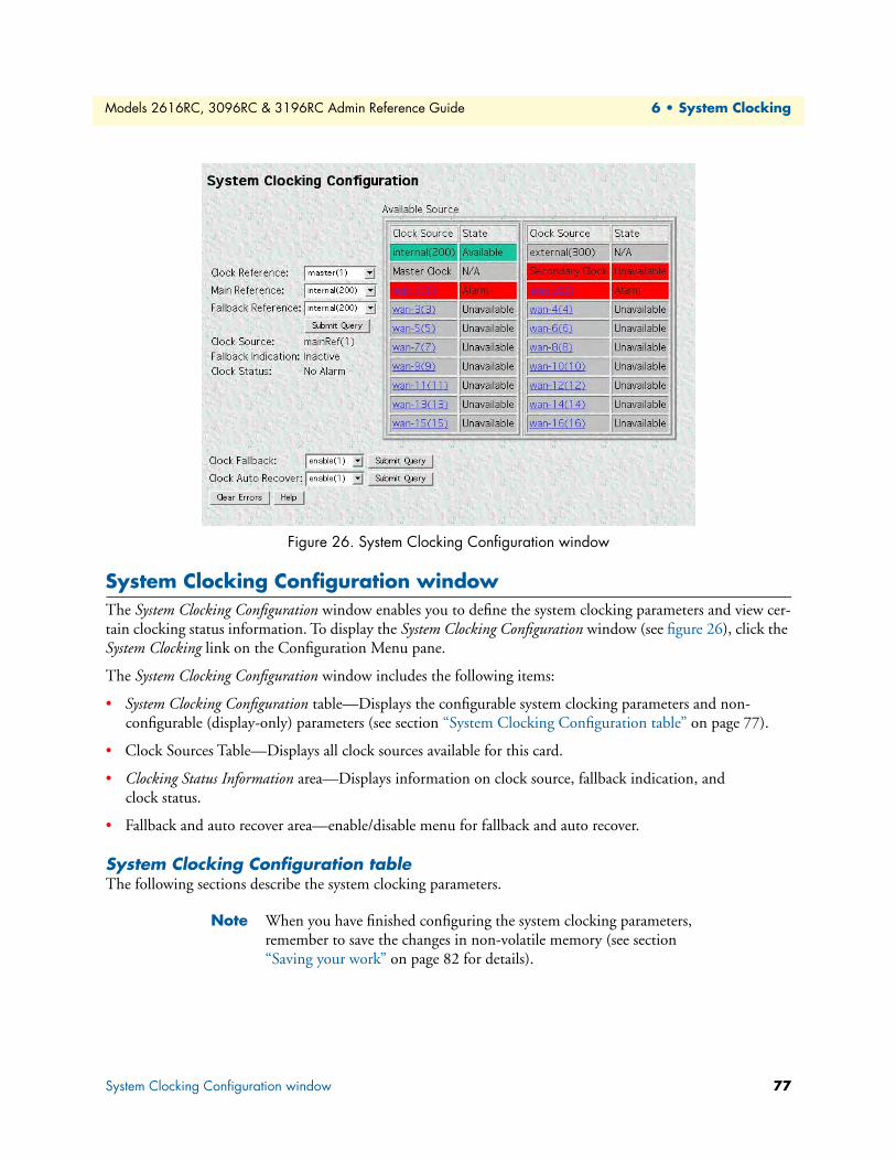
Models 2616RC, 3096RC & 3196RC Admin Reference Guide 6 • System Clocking
Figure 26. System Clocking Configuration window
System Clocking Configuration windowThe System Clocking Configuration window enables you to define the system clocking parameters and view cer-tain clocking status information. To display the System Clocking Configuration window (see figure 26), click the System Clocking link on the Configuration Menu pane.
The System Clocking Configuration window includes the following items:
• System Clocking Configuration table—Displays the configurable system clocking parameters and non-configurable (display-only) parameters (see section “System Clocking Configuration table” on page 77).
• Clock Sources Table—Displays all clock sources available for this card.
• Clocking Status Information area—Displays information on clock source, fallback indication, and clock status.
• Fallback and auto recover area—enable/disable menu for fallback and auto recover.
System Clocking Configuration tableThe following sections describe the system clocking parameters.
Note When you have finished configuring the system clocking parameters, remember to save the changes in non-volatile memory (see section “Saving your work” on page 82 for details).
System Clocking Configuration window 77

Models 2616RC, 3096RC & 3196RC Admin Reference Guide 6 • System Clocking
Clock Reference (sysGSClockMode)The Clock Reference parameter defines the clocking mode for the 3096RC. The clocking mode you assign to the T-DAC defines whether or not it provides the main reference clock to the entire chassis in which the T-DAC resides. Clocking mode options are as follows:
• Master—In master mode (also referred to as primary mode) the T-DAC obtains the main reference clock and provides it to other equipment installed in the chassis with the T-DAC. Because there can only be one master clock source in the chassis, if the T-DAC is the only blade in the chassis, you must define the clock-ing mode as master, but if another blade in the chassis has already been defined as the master, do not define the T-DAC’s clocking mode as master.
• Secondary—In secondary mode, the T-DAC provides a backup (referred to as secondary or fallback) refer-ence clock. It will obtain the main reference clock and provide it to other equipment in the chassis only if the device designated to provide the master clock reference fails. For reliability, we recommend having a sec-ondary clocking blade defined for the chassis.
• Slave—In slave mode the T-DAC does not provide any clock reference. Frequently, the 3096RC will be defined as a slave while another blade (such as the Patton Model 6511) is configured as the master.
To configure the T-DAC’s clocking mode, select one of the following values from the Clock Reference drop-down menu:
• master(1)—The T-DAC will obtain the main reference clock and provide it to the other equipment installed in the chassis with the T-DAC
• secondary(2)—If the device designated to provide the chassis master clock reference fails, the T-DAC—as the secondary source clocking for the chassis —will obtain the main reference clock and provide it to the other equipment installed in the chassis with the T-DAC.
• slave(3)—The T-DAC will not provide clocking reference for any other blade in the chassis
Note In the event of failure of both primary and secondary clocks, all cards in the chassis will switch to their own internal clock.
System Clocking Configuration window 78

Models 2616RC, 3096RC & 3196RC Admin Reference Guide 6 • System Clocking
Main Reference (sysgshDSLClockMainRef) and Fallback Reference (sysgshDSLClockFallbackRef)When a T-DAC’s clocking mode is defined to be Master or Secondary, the T-DAC System Clocking Configura-tion window displays the Main Reference and Fallback Reference parameters. When a T-DACS clocking mode is defined to be Slave, the Main Reference and Fallback Reference parameters do not apply. In slave mode, the T-DAC hides the Main Reference and Fallback Reference parameters to make them inaccessible (See figure 27).
The T-DAC will use the fallback reference if and only if the primary reference becomes unavailable. By default, the clocking Fallback System is factory-disabled. To activate the T-DAC’s fallback system you must enable it (see section“Enable/Disable Fallback System” on page 82).
Figure 27. Clocking scheme for Master and Secondary Cards
When defining the primary and secondary clocking sources, you can select any one of the T-DAC’s WAN ports, the T-DAC internal clock pulse oscillator, or building integrated system timing (BITS). Both parameters will be defined from the same set of possible values. For the fallback reference to serve its purpose, however, you must define it by selecting a value different from the main reference.
The T-DAC will use the main reference as its system clocking source unless the main reference fails or becomes disconnected. When the primary reference becomes unavailable 3096RC will switch to the fallback reference as its system clocking source.
You must also enable the T-DAC’s fallback mechanism (see section“Enable/Disable Fallback System” on page 82). For the T-DAC’s main and fallback clocking references, you can choose:
• One of the T-DAC 4, 8, 12, or 16 WAN ports
• An internal oscillator residing within the T-DAC
• External—BITS clock (building integrated timing system)
Note For the external BITS clock setting to operate, you must connect the BITS clock system at the installation site to the EXT CLOCK con-nector on one of the WAN Access Modules installed in the rear of the ForeFront chassis.
Main Reference
BITS
Internal
T1/E1 (1:16)
Fallback Reference
Master or Secondaryclock to backplane
System Clocking Configuration window 79

Models 2616RC, 3096RC & 3196RC Admin Reference Guide 6 • System Clocking
Figure 28. Available sources for T-DACS for Main and Fallback reference clocks
Cards operating in Slave clocking mode will default to System clock (provided by Master or Secondary cards) for main and fallback reference clock options.
Figure 28 lists available, unavailable, and N/A clock sources. Clock source in use by the T-DACS will be high-lighted in green, while sources under alarm, or sources in failure mode will be highlighted in red. WAN config-uration and status pages can be accessed from the table on figure 28 by clicking on the particular WAN port label (see chapter 20, “T1/E1 Link” on page 285 for more information on T1/E1 port status and configura-tion).
To define the Main Reference and the Fallback Reference, select one of the following values from the drop-down menu:
• wan-1(1)—use WAN port #1 for the clock source
• wan-2(2)—use WAN port #2 for the clock source
• wan-3(3)—use WAN port #3 for the clock source
• wan-4(4)—use WAN port #4 for the clock source
• wan-5(5)—use WAN port #5 for the clock source
• wan-6(6)—use WAN port #6 for the clock source
• wan-7(7)—use WAN port #7 for the clock source
• wan-8(8)—use WAN port #8 for the clock source
• wan-9(9)—use WAN port #9 for the clock source
• wan-10(10)—use WAN port #10 for the clock source
• wan-11(11)—use WAN port #11 for the clock source
• wan-12(12)—use WAN port #12 for the clock source
• wan-13(13)—use WAN port #13 for the clock source
• wan-14(14)—use WAN port #14 for the clock source
System Clocking Configuration window 80
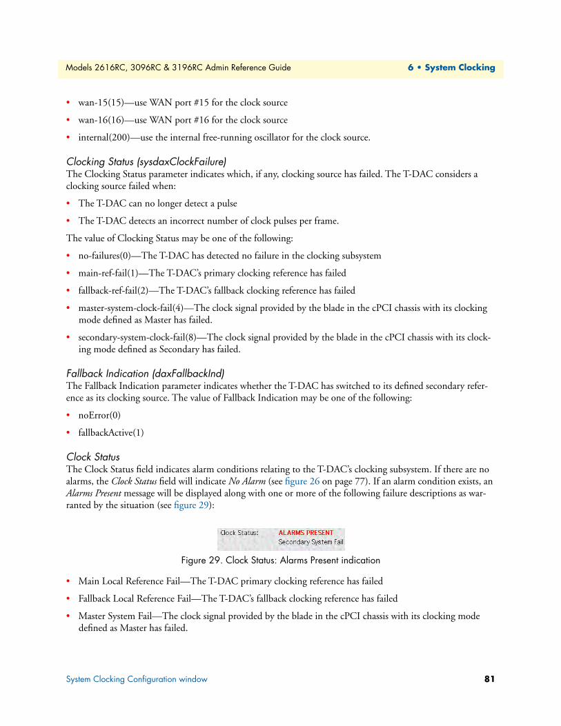
Models 2616RC, 3096RC & 3196RC Admin Reference Guide 6 • System Clocking
• wan-15(15)—use WAN port #15 for the clock source
• wan-16(16)—use WAN port #16 for the clock source
• internal(200)—use the internal free-running oscillator for the clock source.
Clocking Status (sysdaxClockFailure)The Clocking Status parameter indicates which, if any, clocking source has failed. The T-DAC considers a clocking source failed when:
• The T-DAC can no longer detect a pulse
• The T-DAC detects an incorrect number of clock pulses per frame.
The value of Clocking Status may be one of the following:
• no-failures(0)—The T-DAC has detected no failure in the clocking subsystem
• main-ref-fail(1)—The T-DAC’s primary clocking reference has failed
• fallback-ref-fail(2)—The T-DAC’s fallback clocking reference has failed
• master-system-clock-fail(4)—The clock signal provided by the blade in the cPCI chassis with its clocking mode defined as Master has failed.
• secondary-system-clock-fail(8)—The clock signal provided by the blade in the cPCI chassis with its clock-ing mode defined as Secondary has failed.
Fallback Indication (daxFallbackInd)The Fallback Indication parameter indicates whether the T-DAC has switched to its defined secondary refer-ence as its clocking source. The value of Fallback Indication may be one of the following:
• noError(0)
• fallbackActive(1)
Clock StatusThe Clock Status field indicates alarm conditions relating to the T-DAC’s clocking subsystem. If there are no alarms, the Clock Status field will indicate No Alarm (see figure 26 on page 77). If an alarm condition exists, an Alarms Present message will be displayed along with one or more of the following failure descriptions as war-ranted by the situation (see figure 29):
Figure 29. Clock Status: Alarms Present indication
• Main Local Reference Fail—The T-DAC primary clocking reference has failed
• Fallback Local Reference Fail—The T-DAC’s fallback clocking reference has failed
• Master System Fail—The clock signal provided by the blade in the cPCI chassis with its clocking mode defined as Master has failed.
System Clocking Configuration window 81
Models 2616RC, 3096RC & 3196RC Admin Reference Guide 6 • System Clocking
• Secondary System Fail—The clock signal provided by the blade in the cPCI chassis with its clocking mode defined as Secondary has failed.
• Fallback Indication—The T-DAC has switched its clocking source to the fallback reference.
Enable/Disable Fallback System This parameter defines the T-DAC’s clocking fallback mechanism as enabled or disabled. By default, the clock-ing fallback mechanism is enabled at the factory before the T-DAC is shipped. To deactivate the T-DAC’s fall-back system you must disable it. When disabled, the T-DAC will not use the fallback reference clocking source, even if the primary reference becomes unavailable. To define the Enable/Disable Fallback System parameter, select one of the following values from the drop-down box.
• disable(0)
• enable(1)
Once you have defined the desired value for the Enable/Disable Fallback System parameter, you must click the adjacent Submit Query button to save your selection into volatile DRAM.
Enable/Disable Clock Auto Recover SystemThis parameter defines the T-DAC’s clocking auto recover mechanism as enabled or disabled.The clock auto recover feature, when enabled, switches the T-DACS from fallback reference clock to primary reference clock (when this becomes available again). By default, the clocking auto recover mechanism is enabled at the factory before the T-DAC is shipped. To deactivate the T-DAC’s auto recover system you must disable it. When dis-abled, the T-DAC will not switch to primary reference clocking source, even if the primary reference becomes available. To define the Enable/Disable Auto Recover System parameter, select one of the following values from the drop-down box.
• disable(0)
• enable(1)
Once you have defined the desired value for the Enable/Disable Fallback System parameter, you must click the adjacent Submit Query button to save your selection into volatile DRAM.
Saving your workOnce you have defined your desired values for the system clocking parameters, you must click the Record Current Configuration button on the HOME window to save your settings into non-volatile memory (see section “Record Current Configuration (storeConfig(1))” on page 42 for details).
System Clocking Configuration window 82

Models 2616RC, 3096RC & 3196RC Admin Reference Guide 6 • System Clocking
Immediate actions buttonsThe immediate actions buttons with their respective functions are described below:
• Clear Errors—Clicking the Clear Errors button (see figure 26 on page 77) clears the T-DAC’s error condi-tion for all clock signals. For all clock signals, the T-DAC will reset the Dynamic Error variables to a value of noError(0).
• Help—Clicking the Help button displays the DACS Clocking Help window (see figure 30).
Figure 30. System Clocking help window
System Clocking Configuration window 83

Chapter 7 Ethernet
Chapter contentsIntroduction ..........................................................................................................................................................85Ethernet Overview window ...................................................................................................................................85
State (boxEtherAState) ....................................................................................................................................85PrimaryIpAddress (boxEtherAPrimaryIpAddress) ...........................................................................................86PrimaryIpMask (boxEtherAPrimaryIpMask) ...................................................................................................86PrimaryIpFilters (boxEtherAPrimaryIpFilters) ................................................................................................86SecondaryIpAddress (boxEtherASecondaryIpAddress) ....................................................................................86SecondaryIpMask (boxEtherASecondaryIpMask) ............................................................................................86SecondaryIpFilters (boxEtherASecondaryIpFilters) .........................................................................................86Technique (boxEtherATechnique) ..................................................................................................................86
Ethernet Statistics window.....................................................................................................................................87Alignment Errors (dot3StatsAlignmentErrors) ................................................................................................87FCS Errors (dot3StatsFCSErrors) ...................................................................................................................87Single Collision Frames (dot3StatsSingleCollision Frames) .............................................................................87Multiple Collision Frames (dot3StatsMultipleCollisionFrames) ......................................................................87SQE Test Errors (dot3StatsSQETestErrors) ....................................................................................................87Deferred Transmissions (dot3StatsDeferredTransmissions) .............................................................................87Late Collisions (dot3StatsLateCollisions) ........................................................................................................87Excessive Collisions (dot3StatsExcessiveCollisions) .........................................................................................87Other Errors (dot3StatsInternalMacTransmitErrors) ......................................................................................88Carrier Sense Errors (dot3StatsCarrierSenseErrors) .........................................................................................88Received Frames Too Long (dot3StatsFrameTooLongs) .................................................................................88Other Received Errors (dot3StatsInternalMacReceiveErrors) ..........................................................................88Chip Set ID (dot3StatsEtherChipSet) .............................................................................................................88
Ethernet Configuration window............................................................................................................................88State (boxEtherAState) ....................................................................................................................................88Primary IP settings ..........................................................................................................................................89
PrimaryIpAddress (boxEtherAPrimaryIpAddress) ......................................................................................89PrimaryIpMask (boxEtherAPrimaryIpMask) .............................................................................................89PrimaryIpFilters (boxEtherAPrimaryIpFilters) ...........................................................................................89
Secondary IP settings ......................................................................................................................................89SecondaryIpAddress (boxEtherASecondaryIpAddress) ...............................................................................89SecondaryIpMask (boxEtherASecondaryIpMask) ......................................................................................89SecondaryIpFilters (boxEtherASecondaryIpFilters) ....................................................................................90
Technique (boxEtherATechnique) ..................................................................................................................90
84

Models 2616RC, 3096RC & 3196RC Admin Reference Guide 7 • Ethernet
IntroductionThe access server provides management and statistical information in the Ethernet Overview window (see figure 32). Detailed information regarding the SNMP MIB II variables may be downloaded from RFC 1643, Definitions of Managed Objects for the Ethernet-like Interface Types.
Click on Ethernet under the Configuration Menu to display the Ethernet Overview window (see figure 31).
The Ethernet Overview window displays information about the configuration of the Ethernet interface includ-ing IP addresses, subnet masks, and state of the Ethernet link.
The Ethernet Overview window contains the following links:
• Ethernet Statistics link—Clicking on the Ethernet Statistics link takes you to the page where you can see the statistics on the Ethernet interface. For more information about the Ethernet Statistics page, refer to “Ether-net Statistics window” on page 87.
• Modify Parameters—Clicking on the Modify Parameters link takes you to the page where you can change the configuration of your Ethernet interface. For more information about modifying Ethernet settings, refer to “Ethernet Configuration window” on page 88.
Figure 31. Ethernet Overview window
Ethernet Overview windowThe Ethernet Parameters section of the Ethernet Overview window (see figure 31) shows the current configura-tion of the Ethernet interface. The following sections describe each parameter.
State (boxEtherAState)Indicates the state of the Ethernet interface. The following states are valid:
• notInstalled(0)—Ethernet interface is not physically present
• noLinkIndication(1)—no cable is connected to the Ethernet interface. Hub is not seen.
• adminOff(2)—Ethernet interface has been turned off by setting technique to disable
• linkIndication10M(3)—Ethernet is 10M
• linkIndication10Duplex(4)—Ethernet is 10M full duplex
Introduction 85

Models 2616RC, 3096RC & 3196RC Admin Reference Guide 7 • Ethernet
• linkIndication100M(5)—Ethernet is 100M
• linkIndication100Duplex(6)—Ethernet is 100M full duplex
PrimaryIpAddress (boxEtherAPrimaryIpAddress)The primary Ethernet IP address.
PrimaryIpMask (boxEtherAPrimaryIpMask)The primary Ethernet IP subnet mask.
PrimaryIpFilters (boxEtherAPrimaryIpFilters)Filters packets based on the filters assigned to the Primary IP address of the Ethernet port. Enter the Filter ID of a filter configured under Filter IP. Use a comma (,) to separate multiple filters.
SecondaryIpAddress (boxEtherASecondaryIpAddress)The secondary Ethernet IP address.
Note This address is not propagated via RIP.
SecondaryIpMask (boxEtherASecondaryIpMask)The secondary IP Ethernet IP subnet mask.
SecondaryIpFilters (boxEtherASecondaryIpFilters)Filters packets based on the filters assigned to the Secondary IP address of the Ethernet port. Enter the Filter ID of a filter configured under Filter IP. Use a comma (,) to separate multiple filters.
Note Only outbound filters can be applied to the secondary Ethernet. Inbound filters for the secondary Ethernet must be entered in the Pri-mary IP Filter field.
Technique (boxEtherATechnique)Turns Ethernet port off and on. The remote access server must be reset for this setting to take effect.
• disable(0)—Ethernet port is disabled
• static(1)—Ethernet port is turned on. IP address(es) and mask(s) are obtained from data entered under the Ethernet link.
Ethernet Overview window 86

Models 2616RC, 3096RC & 3196RC Admin Reference Guide 7 • Ethernet
Ethernet Statistics windowThe Ethernet Statistics window (see figure 32) shows statistics about the Ethernet interface. To reach this win-dow, select Ethernet Statistics from the Ethernet Overview window (see figure 31 on page 85).
Figure 32. Ethernet Statistics window
Alignment Errors (dot3StatsAlignmentErrors)The number of frames received that are not an integral number of octets in length and do not pass the FCS check.
FCS Errors (dot3StatsFCSErrors)The number of frames received that are an integral number of octets in length but do not pass the FCS check.
Single Collision Frames (dot3StatsSingleCollision Frames)The number of successfully transmitted frames in which there was exactly one collision.
Multiple Collision Frames (dot3StatsMultipleCollisionFrames)The number of successfully transmitted frames in which there was more than one collision.
SQE Test Errors (dot3StatsSQETestErrors)The number of times that the SQE TEST ERROR message is generated by the PLS sublayer.
Deferred Transmissions (dot3StatsDeferredTransmissions)The number of times in which the first transmission attempt is delayed because the medium is busy. This num-ber does not include frames involved in collisions.
Late Collisions (dot3StatsLateCollisions)The number of times that a collision is detected later than 512 bit-times into the transmission of a packet. Five hundred and twelve bit-times corresponds to 51.2 microseconds on a 10 Mbps system.
Excessive Collisions (dot3StatsExcessiveCollisions)The number of frames in which transmission failed due to excessive collisions.
Ethernet Statistics window 87
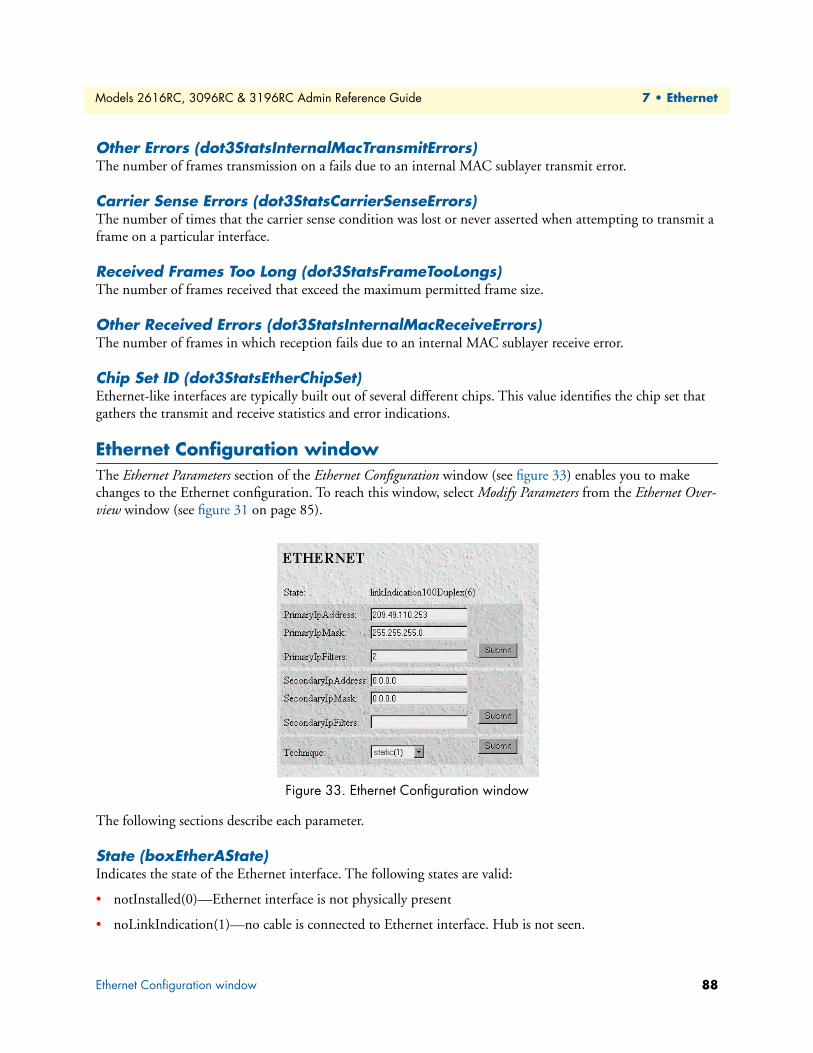
Models 2616RC, 3096RC & 3196RC Admin Reference Guide 7 • Ethernet
Other Errors (dot3StatsInternalMacTransmitErrors)The number of frames transmission on a fails due to an internal MAC sublayer transmit error.
Carrier Sense Errors (dot3StatsCarrierSenseErrors)The number of times that the carrier sense condition was lost or never asserted when attempting to transmit a frame on a particular interface.
Received Frames Too Long (dot3StatsFrameTooLongs)The number of frames received that exceed the maximum permitted frame size.
Other Received Errors (dot3StatsInternalMacReceiveErrors)The number of frames in which reception fails due to an internal MAC sublayer receive error.
Chip Set ID (dot3StatsEtherChipSet)Ethernet-like interfaces are typically built out of several different chips. This value identifies the chip set that gathers the transmit and receive statistics and error indications.
Ethernet Configuration windowThe Ethernet Parameters section of the Ethernet Configuration window (see figure 33) enables you to make changes to the Ethernet configuration. To reach this window, select Modify Parameters from the Ethernet Over-view window (see figure 31 on page 85).
Figure 33. Ethernet Configuration window
The following sections describe each parameter.
State (boxEtherAState)Indicates the state of the Ethernet interface. The following states are valid:
• notInstalled(0)—Ethernet interface is not physically present
• noLinkIndication(1)—no cable is connected to Ethernet interface. Hub is not seen.
Ethernet Configuration window 88
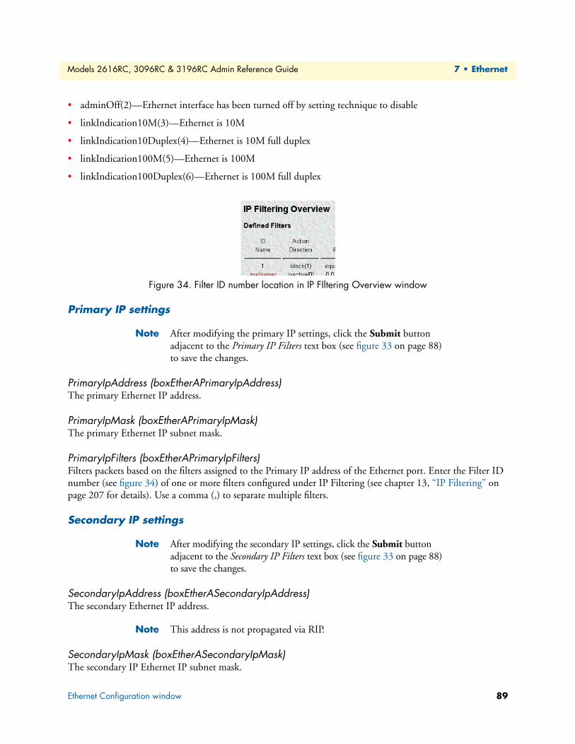
Models 2616RC, 3096RC & 3196RC Admin Reference Guide 7 • Ethernet
• adminOff(2)—Ethernet interface has been turned off by setting technique to disable
• linkIndication10M(3)—Ethernet is 10M
• linkIndication10Duplex(4)—Ethernet is 10M full duplex
• linkIndication100M(5)—Ethernet is 100M
• linkIndication100Duplex(6)—Ethernet is 100M full duplex
Figure 34. Filter ID number location in IP FIltering Overview window
Primary IP settings
Note After modifying the primary IP settings, click the Submit button adjacent to the Primary IP Filters text box (see figure 33 on page 88) to save the changes.
PrimaryIpAddress (boxEtherAPrimaryIpAddress)The primary Ethernet IP address.
PrimaryIpMask (boxEtherAPrimaryIpMask)The primary Ethernet IP subnet mask.
PrimaryIpFilters (boxEtherAPrimaryIpFilters)Filters packets based on the filters assigned to the Primary IP address of the Ethernet port. Enter the Filter ID number (see figure 34) of one or more filters configured under IP Filtering (see chapter 13, “IP Filtering” on page 207 for details). Use a comma (,) to separate multiple filters.
Secondary IP settings
Note After modifying the secondary IP settings, click the Submit button adjacent to the Secondary IP Filters text box (see figure 33 on page 88) to save the changes.
SecondaryIpAddress (boxEtherASecondaryIpAddress)The secondary Ethernet IP address.
Note This address is not propagated via RIP.
SecondaryIpMask (boxEtherASecondaryIpMask)The secondary IP Ethernet IP subnet mask.
Ethernet Configuration window 89
Models 2616RC, 3096RC & 3196RC Admin Reference Guide 7 • Ethernet
SecondaryIpFilters (boxEtherASecondaryIpFilters)Filters packets based on the filters assigned to the Secondary IP address of the Ethernet port. Enter the Filter ID number (see figure 34 on page 89) of one or more filters configured under IP Filtering (see chapter 13, “IP Filtering” on page 207 for details). Use a comma (,) to separate multiple filters.
Technique (boxEtherATechnique)Turns Ethernet port off and on. The remote access server must be reset for this setting to take effect.
Note After modifying the secondary IP settings, click the Submit button adjacent to the Secondary IP Filters text box (see figure 33 on page 88) to save the changes.
• disable(0)—Ethernet port is disabled
• static(1)—Ethernet port is turned on. IP address(es) and mask(s) are obtained from data entered under the Ethernet link.
Ethernet Configuration window 90

Chapter 8 Frame Relay
Chapter contentsIntroduction ..........................................................................................................................................................93Configuring a Frame Relay link.............................................................................................................................93T1/E1 port and DS0 selection...............................................................................................................................93The Frame Relay main window.............................................................................................................................94
Link X (frDlcmiIfIndex) .................................................................................................................................95Status: X (framerelStatus) ..........................................................................................................................95
HDLC Statistics on Link ................................................................................................................................95Transmit (Bits/Sec) (framerelTxOctets) ....................................................................................................95Receive (Bits/Sec) (framerelRxOctets) .......................................................................................................95No Buffers Available (framerelRxNoBufferAvailable) ................................................................................95Data Overflow (framerelRxDataOverflow) ................................................................................................95Message Ends (framerelRxMessageEnds) ...................................................................................................96Packets Too Long (framerelRxPacketTooLong) ........................................................................................96Overflow (framerelRxOverflow) ................................................................................................................96Aborts (FramerelRxAbort) .........................................................................................................................96Bad CRC (framerelRxBadCrc) ..................................................................................................................96Invalid Frames (framerelRxInvalidFrame) .................................................................................................96Tx Underrruns (framerelTxUnderrun) ......................................................................................................96LINK Resets (framerelResets) ....................................................................................................................96Produce Status Change Trap (frTrapState) ................................................................................................96
DLMI window ......................................................................................................................................................96Signalling (frDlcmiState) ................................................................................................................................97Data Link Protocol (frDlcmiAddress) .............................................................................................................97DLCI Length (frDlcmiAddressLen) ................................................................................................................97
Polling Interval (T391)(frDlcmiPollingInterval) .............................................................................................97Full Enquiry Interval (N391)(frDlcmiFullEnquiryInterval) ............................................................................98Error Threshold (N392)(frDlcmiErrorThreshold) ..........................................................................................98Monitored Events (N393)(frDlcmiMonitoredEvents) ....................................................................................98MultiCast Service (frDlcmiMulticast) .............................................................................................................98Max Virtual Circuits (frDlcmiMaxSupportedVCs) .........................................................................................98LMI Interface (frDlcmiInterface) ....................................................................................................................98Bidirectional Polling (frDlcmiPollingBiDir) ...................................................................................................98Polling Verification (T392)(frDlcmiPollingVerification) ................................................................................98
DLCI window .......................................................................................................................................................98DLCI (frCircuitDlci) ......................................................................................................................................99Interface # (FrameIPInterfaceNum) ................................................................................................................99State (frCircuitState) .......................................................................................................................................99Committed Burst (bits) (frCircuitCommitedBurst) ......................................................................................100Excess Burst (bits) (frCircuitExcessBurst) ......................................................................................................100
91

Models 2616RC, 3096RC & 3196RC Admin Reference Guide 8 • Frame Relay
Throughput (bits) (frCircuitThroughput) .....................................................................................................100IP Address (FrameIPAddr) ............................................................................................................................100Congestion (frameEnableCongestion) ...........................................................................................................100
92
Models 2616RC, 3096RC & 3196RC Admin Reference Guide 8 • Frame Relay
IntroductionThe T-DAC offers in-band management over Frame Relay or PPP (point-to-point protocol) links in the T1/E1 channels. The T-DAC’s Frame Relay subsystem manages the in-band management function over Frame Relay links. This chapter discusses in-band management using Frame Relay (for PPP, see chapter 14, “PPP” on page 215).
Configuring a Frame Relay linkThe most common configuration is setting up the T-DAC as a DCE and connecting to a provider’s Frame switch via a T1/E1 line. In this application, the T-DAC will establish a point-to-point link via one or more DLCI’s or virtual channels. Each DLCI is a pipe with an associated far-end IP address.
A Frame Relay link is configured as follows:
• Selecting a T1/E1 DS0 for management using Frame Relay
• Selecting the correct Frame Relay configuration parameters (LMI)
• Assigning an IP address to the DLCI
• Assigning next-hop routes to the new DLCI
T1/E1 port and DS0 selectionThe first stage in setting up a Frame Relay WAN link is configuring one or more DS0s on any T1 or E1 line for Frame Relay in-band management. See chapter 20, “T1/E1 Link” on page 285 for T1/E1 port configuration.
1. Click on the T1/E1 Link under the configuration menu to display the T1/E1 Link Activity main window. Select which T1/E1 port will carry the Frame Relay Link, then click on the View Link of the selected port.
2. Click on Channel Assignment link to access the WAN Circuit Channel Assignment window. Options for the T1/E1 DS0s displayed on this window are:
– clear(9). The T1/E1 DS0s carry user data (default)
– framerelay(3). The selected DS0s will carry management data using Frame Relay
– ppp(5). The selected DS0s will carry management data using PPP
3. Use the drop down menu to select Frame Relay for the designated management channel(s). Set user data DS0s to Clear.
4. Click on the Submit Query button for the configuration to take effect.
The Management DS0 IS now active on your T-DAC. The next stage is to configure Frame Relay and IP routing.
Introduction 93
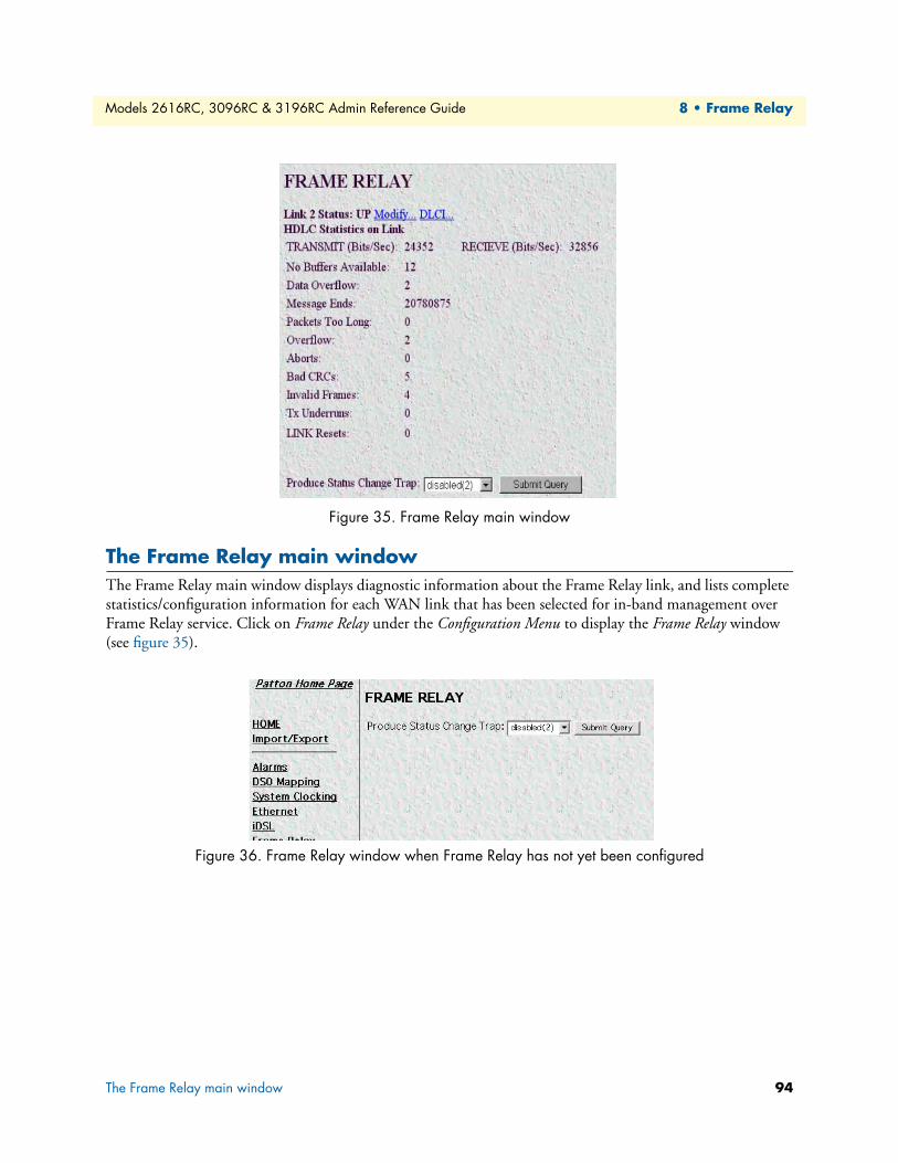
Models 2616RC, 3096RC & 3196RC Admin Reference Guide 8 • Frame Relay
Figure 35. Frame Relay main window
The Frame Relay main windowThe Frame Relay main window displays diagnostic information about the Frame Relay link, and lists complete statistics/configuration information for each WAN link that has been selected for in-band management over Frame Relay service. Click on Frame Relay under the Configuration Menu to display the Frame Relay window (see figure 35).
Figure 36. Frame Relay window when Frame Relay has not yet been configured
The Frame Relay main window 94
Models 2616RC, 3096RC & 3196RC Admin Reference Guide 8 • Frame Relay
Note If the Frame Relay window only shows the Produce Status Change Trap setting (see figure 36), you need to do the following in the T1/E1 Link section:
• Change the Line Type for a WAN port from Other(1) to an appro-priate line type from the menu of options (see section “WAN Cir-cuit Configuration—Modify” on page 296 in chapter 20, “T1/E1 Link” for details).
• Configure at least one channel for Frame Relay (frameRelay3) oper-ation (see section “WAN Circuit Configuration—Channel Assign-ment” on page 300 in chapter 20, “T1/E1 Link” for details).
The Frame Relay main window also has the following links:
• Modify—Clicking on the Modify link enables you to set-up Frame Relay or to change any configuration parameters (see section “DLMI window” on page 96).
• DLCI—The Data Link Connection Identifier (DLCI) provides each PVC with a unique identifier at both the T-DAC and the Frame Relay switch. Within each link (DLMI) there can be multiple Permanent Virtual Circuits (PVC). Each of these PVCs are point-to-point links to remote locations, and define the data path between the T-DAC and the Frame Relay network. Clicking on the DLCI link displays the DLCI window (see “DLCI window” on page 98) that enables you to configure PVCs on the T-DAC.
Link X (frDlcmiIfIndex)The Data Link Management Interface number.
Status: X (framerelStatus)This specifies LMI Link Status. If the management DLCI (either DLCI 0 or 1023) is established, then the sta-tus will be UP. If the management channel has not been established, the status will indicate DOWN.
HDLC Statistics on LinkThe HDLC statistics on the link are defined as follows:
Transmit (Bits/Sec) (framerelTxOctets)This statistic shows the transmit rate in bits-per-second.
Receive (Bits/Sec) (framerelRxOctets)This statistic shows the receive rate in bits-per-second.
No Buffers Available (framerelRxNoBufferAvailable)The number of packets received when no buffers were available.
Data Overflow (framerelRxDataOverflow)The number of packets received with overflow (as indicated by hardware).
The Frame Relay main window 95

Models 2616RC, 3096RC & 3196RC Admin Reference Guide 8 • Frame Relay
Message Ends (framerelRxMessageEnds)The number of packets received with message-correct endings. This value increases each time a valid Frame Relay packet is received.
Packets Too Long (framerelRxPacketTooLong)The number of packets received that were too long.
Overflow (framerelRxOverflow)The number of packets received with overflow (as indicated by software).
Aborts (FramerelRxAbort)The number of packets received that were aborted.
Bad CRC (framerelRxBadCrc)The number of packets received that had bad CRC values.
Invalid Frames (framerelRxInvalidFrame)The number of packets received that had invalid frames.
Tx Underrruns (framerelTxUnderrun)The number of times the transmit buffer was not replenished in time to be sent out on the line.
LINK Resets (framerelResets)Number of times the link management (LMI) was reset.
Produce Status Change Trap (frTrapState)This feature is not currently implemented.
DLMI windowEach Frame Relay instance with the T-DAC is known as the Data Link Management Interface or DLMI. The T-DAC software currently supports one Frame Relay Link, or DLMI, on each of the T1/E1 WAN ports. Frame Relay has a set of protocols responsible for maintaining the link. This is known as the management link interface or LMI.
DLMI window 96
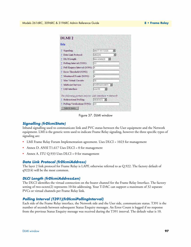
Models 2616RC, 3096RC & 3196RC Admin Reference Guide 8 • Frame Relay
Figure 37. DLMI window
Signalling (frDlcmiState)Inband signalling used to communicate link and PVC status between the User equipment and the Network equipment. LMI is the generic term used to indicate Frame Relay signaling, however the three specific types of signaling are:
• LMI Frame Relay Forum Implementation agreement. Uses DLCI = 1023 for management
• Annex D. ANSI T1.617 Uses DLCI = 0 for management
• Annex A. ITU Q.933 Uses DLCI = 0 for management
Data Link Protocol (frDlcmiAddress)The layer 2 link protocol for Frame Relay is LAPF, otherwise referred to as Q.922. The factory default of q922(4) will be the most common.
DLCI Length (frDlcmiAddressLen)The DLCI identifies the virtual connection on the bearer channel for the Frame Relay Interface. The factory setting of two-octets(2) represents 10-bit addressing. Your T-DAC can support a maximum of 32 separate PVCs or virtual channels per Frame Relay link.
Polling Interval (T391)(frDlcmiPollingInterval)Each side of the Frame Relay interface, the Network side and the User side, communicate status. T391 is the number of seconds between subsequent Status Enquiry messages. An Error Count is logged if no response from the previous Status Enquiry message was received during the T391 interval. The default value is 10.
DLMI window 97

Models 2616RC, 3096RC & 3196RC Admin Reference Guide 8 • Frame Relay
Full Enquiry Interval (N391)(frDlcmiFullEnquiryInterval)Status Enquiry messages are of two different varieties: 1) Link Integrity Verification, which simply exchange sequence numbers between peers and 2) Full Status messages, which is a request from the peer for the list of all active/inactive PVCs. The default is 6.
Error Threshold (N392)(frDlcmiErrorThreshold)N392 is the number of errors (T392 and T391 timeouts and sequence number errors) before action is taken. Action consists of changing all the PVCs from active to inactive. N392 must be less than or equal to N393. The default value is 3.
Monitored Events (N393)(frDlcmiMonitoredEvents)Expected and unexpected events are counted up till the Event Count reaches N393, whereupon the Event Count is cleared and the Error Threshold Count is cleared. Events consist of timer (T391 and T392) expira-tions and received Status Enquiry messages. N393 must be greater or equal to N392. The default value is 4.
MultiCast Service (frDlcmiMulticast)Not currently implemented.
Max Virtual Circuits (frDlcmiMaxSupportedVCs)The maximum number of PVCs determines the amount of internal resources are allocated for the Frame Relay system. The default value is 32.
LMI Interface (frDlcmiInterface)LMI is used in the generic sense as an in-band signaling system. The signaling is slightly different depending on which end of the Frame Relay Interface it is, or in other words its orientation. The User end issues periodic STATUS ENQUIRY messages and waits for a STATUS reply from the Network. The USER setting is correct if the T-DAC is a DCE connecting to a Frame Relay network. It is possible to configure an T-DAC to “look” like a Frame Relay Network. By setting the LMI Interface to NETWORK, you can connect another Frame Device directly to the T-DAC. This is also the setting if you were to connect two T-DAC back-to-back without the benefit of an established Frame Relay network.
Bidirectional Polling (frDlcmiPollingBiDir)Bidirectional Polling pertains only to the Network LMI side. If enabled, the Network LMI issues STATUS ENQUIRY messages and waits for a STATUS reply from the User.
Polling Verification (T392)(frDlcmiPollingVerification)Polling Verification pertains only to the Network LMI side. It is the amount of time permitted without receiv-ing a STATUS ENQUIRY message from the User before Counting an Error.
DLCI windowThe Data Link Connection Identifier (DLCI) provides each PVC with a unique identifier at both the T-DAC and the Frame Relay switch. Within each link (DLMI) there can be multiple Permanent Virtual Circuits (PVC). Each of these PVCs are point-to-point links to remote locations, and define the data path between the T-DAC and the Frame Relay network.
DLCI window 98

Models 2616RC, 3096RC & 3196RC Admin Reference Guide 8 • Frame Relay
Within each DLMI are one or more Data Link Channel Identifier (DLCIs). This is the identification of a PVC within the Frame Relay link.
There will be at least one PVC automatically installed. This is the management DLCI or LMI. This DLCI, often DLCI 0, is the communication channel between the T-DAC and the Frame Relay network switch. This management channel communicates configuration and health information of the Frame Relay link. See figure 38.
Figure 38. DLMI—Configuration View window
DLCI (frCircuitDlci)The Data Link Connection Identifier (DLCI) for this virtual circuit.
Note DLCIs can automatically appear if your Frame Relay Service provider has already configured your link. In this case, all you will need to enter is the IP address of the router at the far end of the link.
Interface # (FrameIPInterfaceNum)The interface number assigned to a DLCI. This is a variable number which is assigned from a resource pool within the T-DAC.
State (frCircuitState)This is the state of the interface with the following definitions:
• invalid(1)—Use this setting to delete DLCI’s on your T-DAC’s configuration view. To delete a DLCI, sim-ply set the state to invalid(1) and Submit Query. Note: A deleted DLCI will reappear if your service pro-vider’s Frame Relay switch is still configured to recognize that DLCI. This occurs after a Frame Relay Full Status Enquiry.
• active(2)—The link is up and passing data. This is the desired condition of the link.
• invalid(3)—The link is down and not passing data. Reasons for this may be your service provider hasn’t enabled your service or the link is not yet connected to your T-DAC.
DLCI window 99
Models 2616RC, 3096RC & 3196RC Admin Reference Guide 8 • Frame Relay
• needIPaddr(4)—This is when the IP address needs to be entered for this DLCI.
• wait4peer(5)—In this state, the Link is waiting for the far end to synchronize.
Committed Burst (bits) (frCircuitCommitedBurst)This specifies the committed data rate for the link in bits-per-second.
Excess Burst (bits) (frCircuitExcessBurst)This specifies the excess data rate for the link in bits-per-second.
Throughput (bits) (frCircuitThroughput)This specifies the throughput for the link in bits-per-second.
IP Address (FrameIPAddr)As all of the interfaces on the T-DAC run in un-numbered mode, the IP address to enter is that of the far end router. This is not the IP address of the T-DAC. After the IP address is entered, it will appear as a point-to-point link in the IP routing table with this address.
Congestion (frameEnableCongestion)This option enables or disables congestion tracking.
• enable(0)—Enables congestion tracking
• disable(1)—Disables congestion tracking
DLCI window 100

Chapter 9 G.SHDSL (Model 3096RC)
Chapter contentsIntroduction ........................................................................................................................................................103G.SHDSL Port Configuration window ...............................................................................................................103
G.SHDSL port summary status ....................................................................................................................104Operator action buttons ................................................................................................................................105G.SHDSL port status ....................................................................................................................................106
Port # (gshDSLPortNum) .......................................................................................................................106Circuit ID (gshDSLCircuitID) ................................................................................................................106State (gshDSLState) ................................................................................................................................107
Clearing an error condition ............................................................................................................... 107Color-coded port status indicators ...........................................................................................................108Desired State (gshDSLDesireState) .........................................................................................................108Test Mode (sDSLTMSelection) ..............................................................................................................108Test Pattern (gshDSLPattSelect) .............................................................................................................110Payload Rate (gshDSLPayloadRate) ........................................................................................................112Error Code (gshDSLErrorCode) .............................................................................................................112Saving your work ....................................................................................................................................112
G.SHDSL Port Details window...........................................................................................................................113Operator action buttons ................................................................................................................................114G.SHDSL port status and statistics tables .....................................................................................................116
General Info table ...................................................................................................................................116Activation State Info table .......................................................................................................................117Fifo Info table .........................................................................................................................................118Data Path Info table ................................................................................................................................118History Details table ...............................................................................................................................119
Port configuration tables ...............................................................................................................................120Change Config button ............................................................................................................................121Cancel button .........................................................................................................................................121
CO Configuration table ................................................................................................................................121CPE Configuration table ..............................................................................................................................123Additional CPE parameters ...........................................................................................................................124Hardware Loop Status Parameters .................................................................................................................125Saving your work ..........................................................................................................................................126Hard Reset This Port button .........................................................................................................................126
G.SHDSL Port History of Near-End Performance window ................................................................................127Back To System History Page hyperlink .......................................................................................................128To Port Details Page hyperlink .....................................................................................................................128Error Statistics table ......................................................................................................................................128
G.SHDSL Line Provision window.......................................................................................................................129Back button ..................................................................................................................................................129
101

Models 2616RC, 3096RC & 3196RC Admin Reference Guide 9 • G.SHDSL (Model 3096RC)
Refresh Current Page button .........................................................................................................................129Calculate Best Line Rate button ....................................................................................................................130Cancel button ...............................................................................................................................................130
102
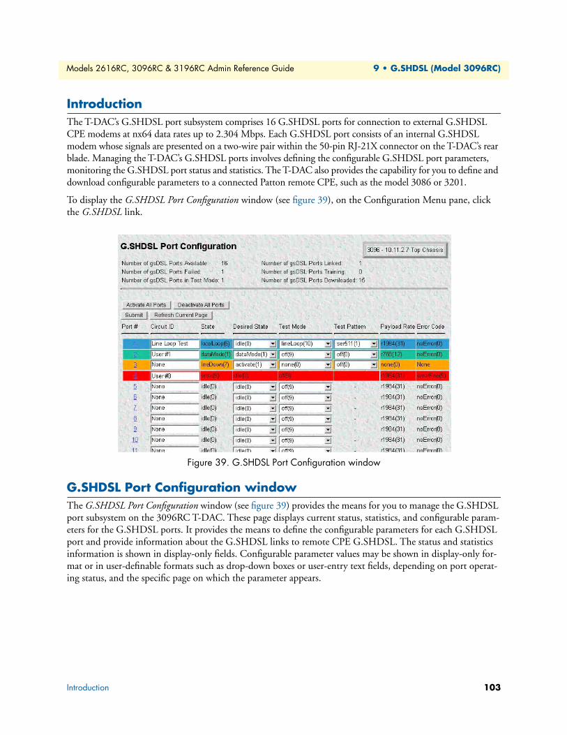
Models 2616RC, 3096RC & 3196RC Admin Reference Guide 9 • G.SHDSL (Model 3096RC)
IntroductionThe T-DAC’s G.SHDSL port subsystem comprises 16 G.SHDSL ports for connection to external G.SHDSL CPE modems at nx64 data rates up to 2.304 Mbps. Each G.SHDSL port consists of an internal G.SHDSL modem whose signals are presented on a two-wire pair within the 50-pin RJ-21X connector on the T-DAC’s rear blade. Managing the T-DAC’s G.SHDSL ports involves defining the configurable G.SHDSL port parameters, monitoring the G.SHDSL port status and statistics. The T-DAC also provides the capability for you to define and download configurable parameters to a connected Patton remote CPE, such as the model 3086 or 3201.
To display the G.SHDSL Port Configuration window (see figure 39), on the Configuration Menu pane, click the G.SHDSL link.
Figure 39. G.SHDSL Port Configuration window
G.SHDSL Port Configuration windowThe G.SHDSL Port Configuration window (see figure 39) provides the means for you to manage the G.SHDSL port subsystem on the 3096RC T-DAC. These page displays current status, statistics, and configurable param-eters for the G.SHDSL ports. It provides the means to define the configurable parameters for each G.SHDSL port and provide information about the G.SHDSL links to remote CPE G.SHDSL. The status and statistics information is shown in display-only fields. Configurable parameter values may be shown in display-only for-mat or in user-definable formats such as drop-down boxes or user-entry text fields, depending on port operat-ing status, and the specific page on which the parameter appears.
Introduction 103

Models 2616RC, 3096RC & 3196RC Admin Reference Guide 9 • G.SHDSL (Model 3096RC)
The G.SHDSL Port Configuration window provides links to the windows shown in the figure 40.
Figure 40. G.SHDSL management windows map
The G.SHDSL Port Configuration web management page shows the high-level status summary for all 16 G.SHDSL ports, plus a more detailed summary status for each individual port. The page provides this infor-mation in two tables:
• G.SHDSL Port Summary Status
• G.SHDSL Port Status (see page 106)
The contents of the two tables is described in subsequent paragraphs.
Figure 41. G.SHDSL port summary status section of G.SHDSL Port Configuration window
G.SHDSL port summary statusThe G.SHDSL port summary status section of the G.SHDSL Port Configuration window (see figure 41) dis-plays the following parameters:
• Number of gshDSL Ports Available (numgshDSLPorts)—Total number of G.SHDSL ports currently avail-able for use. The sum of the values in Number of G.SHDSL Available and Number of G.SHDSL Failed will be 16. The T-DAC determines this parameter value during power up when the G.SHDSL modems are tested for availability or failure.
• Number of gshDSL Ports Failed (numgshDSLPortsFailed)—Total number of G.SHDSL ports with hardware failures. The sum of the values in Number of G.SHDSL Available and Number of G.SHDSL Failed will be 16. The T-DAC determines this parameter value during power up when the G.SHDSL modems are tested for availability or failure.
G.SHDSL Port Configuration
G.SHDSL Port Details
G.SHDSL LineProvision Tool
G.SHDSL PortNear-End Statistics
Back toSystem History window
G.SHDSL Port Configuration window 104

Models 2616RC, 3096RC & 3196RC Admin Reference Guide 9 • G.SHDSL (Model 3096RC)
• Number of gshDSL Ports in Test Mode (numgshDSLPortsInTestMode)—Total number of G.SHDSL ports for which the T-DAC operator has defined the Test Mode parameter defined as one of the following:
- Local Loop
- Remote Serial Loops
- Remote Ethernet Loops
- Line Loop
• Number of gshDSL Ports Linked (numgshDSLPortsLinked)—Total number of G.SHDSL ports which have established a logical data link connection with a remote G.SHDSL CPE modem. The two devices have syn-chronized and are able to pass data.
• Number of gshDSL Ports Training (numgshDSLTraining)—Total number of G.SHDSL ports which are in the process of attempting to establish a logical data link connection with a remote G.SHDSL CPE modem.
• Number of gshDSL Ports Downloaded (numgshDSLPortsDownloaded)—Total number of G.SHDSL ports which have loaded their operating software from NVRAM into the port’s digital signal processor (DSP) chip.
Figure 42. G.SHDSL Port Configuration window operator action buttons
Operator action buttonsThe operator action buttons (see figure 42) do the following:
• Activate All Ports—Pressing this button activates all iDSL ports
• Deactivate All Ports—Pressing this button deactivates all iDSL ports
• Submit—When defining values for configurable parameters on the page, you will use this button to save your work. When you click the Submit button, the T-DAC writes the currently displayed parameter values to volatile DRAM. You will also see a second Submit button at the bottom of the page, which provides exactly the same function.
• Refresh Current Page—Pressing this button refreshes the display. When you click the Refresh Current Page button, the T-DAC retrieves parameter values currently stored in DRAM and displays them on the page. Any values entered or selected since you last clicked the Submit button will be overwritten with val-ues retrieved from DRAM. After defining new values for configurable parameters on this page, use this but-ton to update the display to reflect any resulting changes in G.SHDSL port status.
G.SHDSL Port Configuration window 105
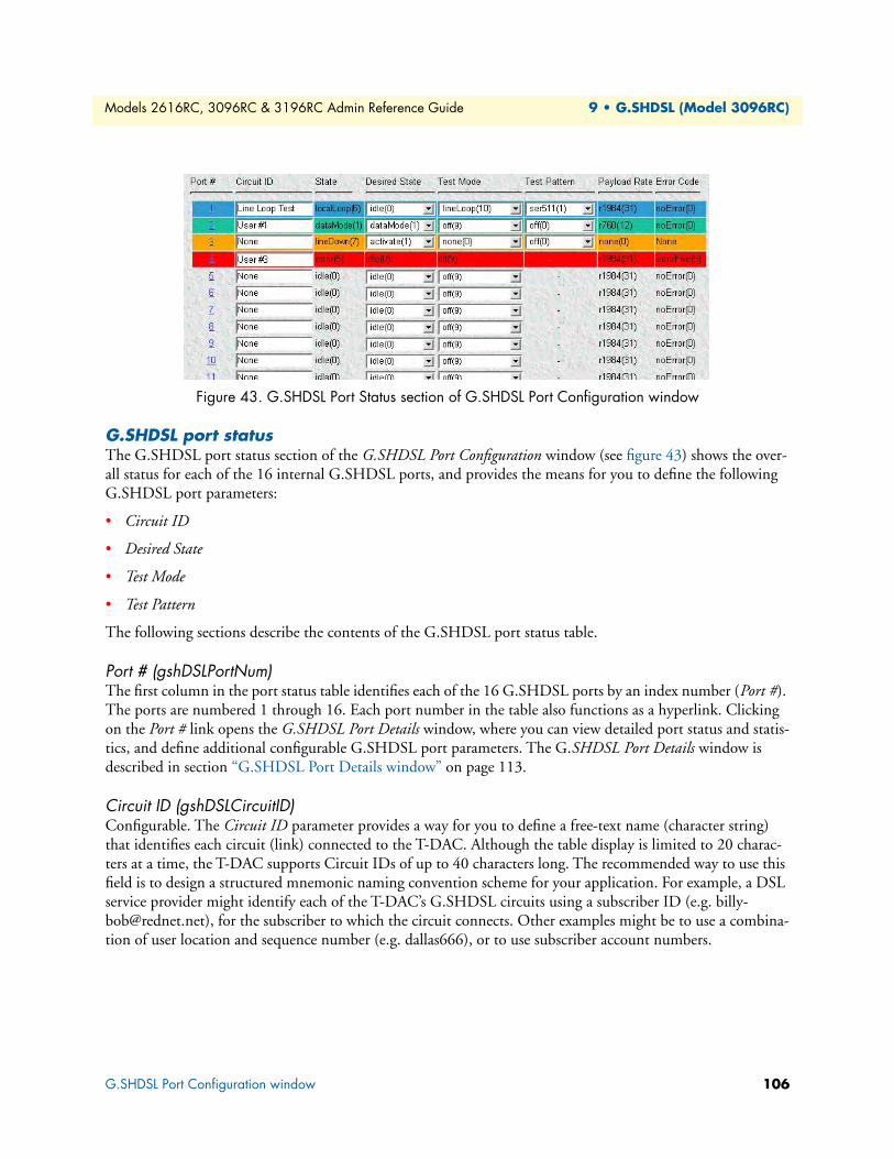
Models 2616RC, 3096RC & 3196RC Admin Reference Guide 9 • G.SHDSL (Model 3096RC)
Figure 43. G.SHDSL Port Status section of G.SHDSL Port Configuration window
G.SHDSL port statusThe G.SHDSL port status section of the G.SHDSL Port Configuration window (see figure 43) shows the over-all status for each of the 16 internal G.SHDSL ports, and provides the means for you to define the following G.SHDSL port parameters:
• Circuit ID
• Desired State
• Test Mode
• Test Pattern
The following sections describe the contents of the G.SHDSL port status table.
Port # (gshDSLPortNum)The first column in the port status table identifies each of the 16 G.SHDSL ports by an index number (Port #). The ports are numbered 1 through 16. Each port number in the table also functions as a hyperlink. Clicking on the Port # link opens the G.SHDSL Port Details window, where you can view detailed port status and statis-tics, and define additional configurable G.SHDSL port parameters. The G.SHDSL Port Details window is described in section “G.SHDSL Port Details window” on page 113.
Circuit ID (gshDSLCircuitID)Configurable. The Circuit ID parameter provides a way for you to define a free-text name (character string) that identifies each circuit (link) connected to the T-DAC. Although the table display is limited to 20 charac-ters at a time, the T-DAC supports Circuit IDs of up to 40 characters long. The recommended way to use this field is to design a structured mnemonic naming convention scheme for your application. For example, a DSL service provider might identify each of the T-DAC’s G.SHDSL circuits using a subscriber ID (e.g. [email protected]), for the subscriber to which the circuit connects. Other examples might be to use a combina-tion of user location and sequence number (e.g. dallas666), or to use subscriber account numbers.
G.SHDSL Port Configuration window 106
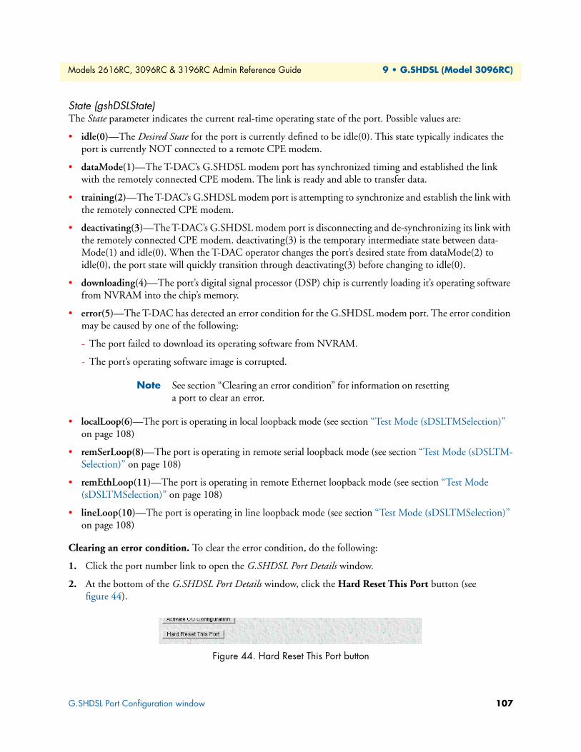
Models 2616RC, 3096RC & 3196RC Admin Reference Guide 9 • G.SHDSL (Model 3096RC)
State (gshDSLState)The State parameter indicates the current real-time operating state of the port. Possible values are:
• idle(0)—The Desired State for the port is currently defined to be idle(0). This state typically indicates the port is currently NOT connected to a remote CPE modem.
• dataMode(1)—The T-DAC’s G.SHDSL modem port has synchronized timing and established the link with the remotely connected CPE modem. The link is ready and able to transfer data.
• training(2)—The T-DAC’s G.SHDSL modem port is attempting to synchronize and establish the link with the remotely connected CPE modem.
• deactivating(3)—The T-DAC’s G.SHDSL modem port is disconnecting and de-synchronizing its link with the remotely connected CPE modem. deactivating(3) is the temporary intermediate state between data-Mode(1) and idle(0). When the T-DAC operator changes the port’s desired state from dataMode(2) to idle(0), the port state will quickly transition through deactivating(3) before changing to idle(0).
• downloading(4)—The port’s digital signal processor (DSP) chip is currently loading it’s operating software from NVRAM into the chip’s memory.
• error(5)—The T-DAC has detected an error condition for the G.SHDSL modem port. The error condition may be caused by one of the following:
- The port failed to download its operating software from NVRAM.
- The port’s operating software image is corrupted.
Note See section “Clearing an error condition” for information on resetting a port to clear an error.
• localLoop(6)—The port is operating in local loopback mode (see section “Test Mode (sDSLTMSelection)” on page 108)
• remSerLoop(8)—The port is operating in remote serial loopback mode (see section “Test Mode (sDSLTM-Selection)” on page 108)
• remEthLoop(11)—The port is operating in remote Ethernet loopback mode (see section “Test Mode (sDSLTMSelection)” on page 108)
• lineLoop(10)—The port is operating in line loopback mode (see section “Test Mode (sDSLTMSelection)” on page 108)
Clearing an error condition. To clear the error condition, do the following:
1. Click the port number link to open the G.SHDSL Port Details window.
2. At the bottom of the G.SHDSL Port Details window, click the Hard Reset This Port button (see figure 44).
Figure 44. Hard Reset This Port button
G.SHDSL Port Configuration window 107

Models 2616RC, 3096RC & 3196RC Admin Reference Guide 9 • G.SHDSL (Model 3096RC)
Figure 45. Color-coded port status example
Color-coded port status indicatorsThe G.SHDSL port status table uses the following color-codes (see figure 45) to indicate the status of each port:
• Green—The port is currently in dataMode(1) state. A G.SHDSL link is established with the remote CPE. The link is ready and able to transfer data.
• Blue—The port is operating in one of the following test modes
- localLoop(6)
- remSerLoop(8)
- remEthLoop(11)
- lineLoop(10)
• Yellow—One of the following is occurring:
- The port is currently in training(2) state and the 4-minute link establishment timer has not expired
- The port is in deactivating(3) state
- The port is in downloading(4) state
• Orange—The port is in training(2) state and could not establish the G.SHDSL link (move to dataMode(2) state) within 4 minutes.
• Red—The port is currently in error(5) state (see section “State (gshDSLState)” on page 107)
Desired State (gshDSLDesireState)Configurable. Indicates the T-DAC operator’s current intentions for the port.
• idle(0)—Default value. The T-DAC operator intends the port for future use. Use this value when the port is not currently connected to a remote CPE modem.
• dataMode(1)—The T-DAC operator intends the port to be connected to a remote CPE modem for current active use
Test Mode (sDSLTMSelection)Configurable when the value of port State is one of the following:
• dataMode(1)
• localLoop(6)
G.SHDSL Port Configuration window 108
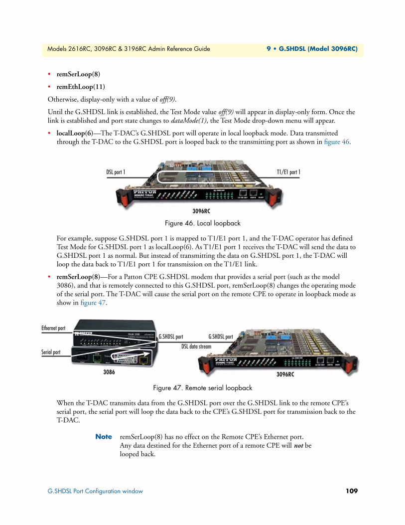
Models 2616RC, 3096RC & 3196RC Admin Reference Guide 9 • G.SHDSL (Model 3096RC)
E
S
• remSerLoop(8)
• remEthLoop(11)
Otherwise, display-only with a value of off(9).
Until the G.SHDSL link is established, the Test Mode value off(9) will appear in display-only form. Once the link is established and port state changes to dataMode(1), the Test Mode drop-down menu will appear.
• localLoop(6)—The T-DAC’s G.SHDSL port will operate in local loopback mode. Data transmitted through the T-DAC to the G.SHDSL port is looped back to the transmitting port as shown in figure 46.
Figure 46. Local loopback
For example, suppose G.SHDSL port 1 is mapped to T1/E1 port 1, and the T-DAC operator has defined Test Mode for G.SHDSL port 1 as localLoop(6). As T1/E1 port 1 receives the T-DAC will send the data to G.SHDSL port 1 as normal. But instead of transmitting the data on G.SHDSL port 1, the T-DAC will loop the data back to T1/E1 port 1 for transmission on the T1/E1 link.
• remSerLoop(8)—For a Patton CPE G.SHDSL modem that provides a serial port (such as the model 3086), and that is remotely connected to this G.SHDSL port, remSerLoop(8) changes the operating mode of the serial port. The T-DAC will cause the serial port on the remote CPE to operate in loopback mode as show in figure 47.
Figure 47. Remote serial loopback
When the T-DAC transmits data from the G.SHDSL port over the G.SHDSL link to the remote CPE’s serial port, the serial port will loop the data back to the CPE’s G.SHDSL port for transmission back to the T-DAC.
Note remSerLoop(8) has no effect on the Remote CPE’s Ethernet port. Any data destined for the Ethernet port of a remote CPE will not be looped back.
3096RC
T1/E1 port 1DSL port 1
thernet port
erial port
3086
G.SHDSL port G.SHDSL port
DSL data stream
3096RC
G.SHDSL Port Configuration window 109

Models 2616RC, 3096RC & 3196RC Admin Reference Guide 9 • G.SHDSL (Model 3096RC)
E
S
• remEthLoop(11)—For Patton CPE G.SHDSL modems that provide an Ethernet port, (such as models 3201 and 3086), and are remotely connected to this G.SHDSL port, remEthLoop(11) changes the operat-ing mode of the Ethernet port. The T-DAC will cause the Ethernet port on the remote CPE to operate in loopback mode as show in figure 48.
Figure 48. Remote Ethernet loopback
When the T-DAC transmits data from the G.SHDSL port over the G.SHDSL link to the remote CPE’s Ethernet port, the Ethernet port will loop the data back to the CPE’s G.SHDSL port for transmission back to the T-DAC.
Note In the case where the remote CPE is a Patton Model 3086, remEth-Loop(8) has no effect on the remote CPE’s serial port. remEth-Loop(8) will NOT cause any data transmitted to the serial port of a remote CPE to be looped back.
• lineLoop(10)—The T-DAC’s G.SHDSL port will operate in line loopback mode as shown in figure 49. For the CPE remotely connected to this port, you can use lineLoop(10) mode to test the G.SHDSL link from the CPE to the T-DAC and back to the CPE.
Figure 49. Line loopback
When a CPE transmits data to a T-DAC’s G.SHDSL port with Test Mode defined as lineLoop(10), the G.SHDSLport will loop the data back to the CPE.
• off(9)—The default value for Test Mode. Appears as a display-only value.
Test Pattern (gshDSLPattSelect)Configurable, but only when the value of State is one of the following:
• dataMode(1)
• localLoop(6)
3096RC
DSL data stream
3086
thernet port
erial port
G.SHDSL port G.SHDSL port
3096RC
DSL
3086
Ethernet
TDM
G.SHDSL Port Configuration window 110
Models 2616RC, 3096RC & 3196RC Admin Reference Guide 9 • G.SHDSL (Model 3096RC)
• remSerLoop(8)
• remEthLoop(11)
Otherwise, display-only with a value of off(9).
Until the G.SHDSL link is established, the G.SHDSL Port Status table will display a dash (-) in the Test Pat-tern column using display-only format. Once the G.SHDSL link is established and the port state changes to datamode(1), the Test Pattern drop-down menu will appear.
The Test Pattern parameter defines which test pattern the T-DAC will generate and transmit. The T-DAC’s will transmit the selected test pattern to the destination port defined by the value of Test Mode (see section “Test Mode (sDSLTMSelection)” on page 108). To define the Test Pattern, select one of the following values from the drop-down menu, then click the Submit button:
• off(0)
• ser511(1)
• ser511E(2)
• ser2047(3)
• ser2047E(4)
• ser63(5)
• ser63E(6)
• eth511(7)
• eth511E(8)
• eth2047(9)
• eth2047E(10)
• eth63(11)
• eth63E(12)
Once you click the Submit button, the Test Pattern column will display the newly defined value in display-only format, together with a check box labelled Off. To disable the test or to change the test pattern, click the Off check box and click the Submit button.
G.SHDSL Port Configuration window 111

Models 2616RC, 3096RC & 3196RC Admin Reference Guide 9 • G.SHDSL (Model 3096RC)
Payload Rate (gshDSLPayloadRate)Display-only on the G.SHDSL Port Status page. Configurable on the G.SHDSL Port Details window.
Shows the currently defined payload rate (i.e. data rate as opposed to line rate) for the G.SHDSL link. The fol-lowing values of Payload Rates may be defined for T-DAC G.SHDSL ports:
Error Code (gshDSLErrorCode)Display-only.
• noError(0)
• errorOne(1)
• errorTwo(2)
• errorThree(3)
• errorFour(4)
• errorFive(5)
• errorSix(6)
• errorSeven(7)
Saving your workOnce you have defined your desired values for the configurable parameters shown in the G.SHDSL Port Status table, you must click either of the two Submit buttons to save your settings into volatile DRAM. Clicking either of the submit query buttons will save the configurable parameter values displayed for all 16 G.SHDSL ports. Once you click the button, the T-DAC will implement the changes immediately.
Note To save your changes permanently, (i.e. when the T-DAC is powered down) you must visit the T-DAC HOME page, and click the Save Current Configuration button. When you click the Save Current Configuration button, the T-DAC will copy the configuration cur-rently stored in volatile DRAM into non-volatile Flash memory for permanent storage.
• r64(1) • r128(2) • r192(3) • r256(4) • r320(5) • r384(6)
• r448(7) • r512(8) • r576(9) • r640(10) • r704(11) • r768(12)
• r832(13) • r896(14) • r960(15) • r1024(16) • r1088(17) • r1152(18)
• r1216(19) • r1280(20) • r1344(21) • r1408(22) • r1472(23) • r1536(24)
• r1600(25) • r1664(26) • r1728(27) • r1792(28) • r1856(29) • r1920(30)
• r1984(31) • r2048(32) • r2112(33) • r2176(34) • r2240(35) • r2304(36)
G.SHDSL Port Configuration window 112
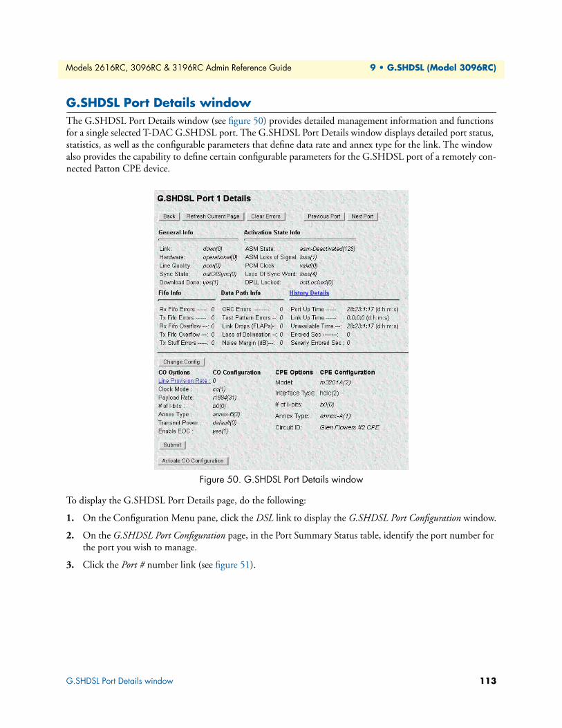
Models 2616RC, 3096RC & 3196RC Admin Reference Guide 9 • G.SHDSL (Model 3096RC)
G.SHDSL Port Details windowThe G.SHDSL Port Details window (see figure 50) provides detailed management information and functions for a single selected T-DAC G.SHDSL port. The G.SHDSL Port Details window displays detailed port status, statistics, as well as the configurable parameters that define data rate and annex type for the link. The window also provides the capability to define certain configurable parameters for the G.SHDSL port of a remotely con-nected Patton CPE device.
Figure 50. G.SHDSL Port Details window
To display the G.SHDSL Port Details page, do the following:
1. On the Configuration Menu pane, click the DSL link to display the G.SHDSL Port Configuration window.
2. On the G.SHDSL Port Configuration page, in the Port Summary Status table, identify the port number for the port you wish to manage.
3. Click the Port # number link (see figure 51).
G.SHDSL Port Details window 113

Models 2616RC, 3096RC & 3196RC Admin Reference Guide 9 • G.SHDSL (Model 3096RC)
Figure 51. Port # links
The G.SHDSL Port Details window is organized into the following groups:
• Operator action buttons at the top of the page
• G.SHDSL Port Status and Statistics tables below the operator action buttons
• G.SHDSL Port Parameters tables on the lower part of the page.
The G.SHDSL Port Details window is related to other web management windows via links as show in figure 52.
Figure 52. G.SHDSL Web Management windows map
The following sections describe the contents of the G.SHDSL Port Details window.
Figure 53. Operator action buttons section of the G.SHDSL Port Details window
Operator action buttonsThe G.SHDSL Port Details window provides the following operator action buttons (see figure 53):
• Back—Displays the previous page. When you click the Back button the T-DAC moves you back one level in the web management windows map (see figure 52 on page 114) to the G.SHDSL Port Configuration window.
G.SHDSL Ports
G.SHDSL Port Details
G.SHDSL LineProvision Tool
G.SHDSL PortNear-End Statistics
Back toSystem History window
G.SHDSL Port Details window 114
Models 2616RC, 3096RC & 3196RC Admin Reference Guide 9 • G.SHDSL (Model 3096RC)
• Refresh Current Page—Refreshes the display. When you click the Refresh Current Page button, the T-DAC retrieves parameter values currently stored in DRAM and displays them on the page. Any config-urable parameter values entered or selected since you last clicked (submit) will be overwritten with values retrieved from DRAM. When monitoring operating status or statistics, or when defining new values for configurable parameters, use this button to update the display. You can watch any changes take place as they are reflected on the G.SHDSL port status display.
• Clear Errors—Clears all errors on this port. Resets the port statistical error counters to zero. A burst of errors typically occurs during port activation. Five seconds after the port enters dataMode(1) the T-DAC will reset the statistical error counters to zero to clear these expected startup errors. The port error counts accumulate from that point forward. Each time you click the Clear Errors button the T-DAC will clear all errors for this port, resetting the counters to zero.
Clicking on the Clear Errors button resets the following counters:
- CRC Errors (gshDSLCRCErrors)
- Test Pattern Errors (gshDSLPattErrorCnt)
- Link Drops (FLAPs) (gshDSLFlapCnt)
- Loss of Delineation (gshDSLLOCDelineation)
- Rx Fifo Errors (gshDSLRxFifoErr)
- Tx Fifo Errors (gshDSLTxFifoErr)
- Rx Fifo Overflow (gshDSLRxFifoOverflowErr)
- Tx Fifo Overflow (gshDSLTxFifoOverflowErr)
- Tx Stuff Errors (gshDSLTxStuffError)
- Errored Sec (gshDSLErroredSec)
- Severely Errored Sec (gshDSLSeverlyErroredSec)
• Previous Port—Displays the G.SHDSL Port Details page for the next lower numbered G.SHDSL port. For example, if you are viewing the G.SHDSL Port 3 Details page, when you click the Previous Port button the T-DAC will display the G.SHDSL Port 2 Details page. If you are viewing Port 1, the page will be refreshed.
• Next Port—Displays the G.SHDSL Port Details page for the next higher numbered G.SHDSL port. For example, if you are viewing the G.SHDSL Port 3 Details page, when you click the Next Port button the T-DAC will display the G.SHDSL Port 4 Details page. If you are viewing Port 16, the page will be refreshed.
G.SHDSL Port Details window 115
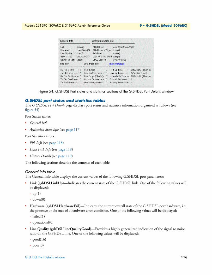
Models 2616RC, 3096RC & 3196RC Admin Reference Guide 9 • G.SHDSL (Model 3096RC)
Figure 54. G.SHDSL Port status and statistics sections of the G.SHDSL Port Details window
G.SHDSL port status and statistics tablesThe G.SHDSL Port Details page displays port status and statistics information organized as follows (see figure 54):
Port Status tables:
• General Info
• Activation State Info (see page 117)
Port Statistics tables:
• Fifo Info (see page 118)
• Data Path Info (see page 118)
• History Details (see page 119)
The following sections describe the contents of each table.
General Info tableThe General Info table displays the current values of the following G.SHDSL port parameters:
• Link (gshDSLLinkUp)—Indicates the current state of the G.SHDSL link. One of the following values will be displayed:
- up(1)
- down(0)
• Hardware (gshDSLHardwareFail)—Indicates the current overall state of the G.SHDSL port hardware, i.e. the presence or absence of a hardware error condition. One of the following values will be displayed:
- failed(1)
- operational(0)
• Line Quality (gshDSLLineQualityGood)—Provides a highly generalized indication of the signal to noise ratio on the G.SHDSL line. One of the following values will be displayed:
- good(16)
- poor(0)
G.SHDSL Port Details window 116
Models 2616RC, 3096RC & 3196RC Admin Reference Guide 9 • G.SHDSL (Model 3096RC)
• Sync State (gshDSLSyncState)—Indicates the current state of synchronization on the line connecting this G.SHDSL port and the remote CPE modem. One of the following values will be displayed:
- outOfSync(0)
- acquiringSync(64)
- inSync(128)
- losingSync(192)
• Download Done (gshDSLDownloadDone)—Indicates whether the port’s DSP has loaded its operational software from NVRAM. One of the following values will be displayed:
- yes(1)
- no(0)
Activation State Info tableThe operating software for each G.SHDSL port includes a module called the Activation State Manager (ASM). The Activation State Info table provides information about the current software state for the port. The current values of the following G.SHDSL port parameters are shown in display-only format:
• ASM State (gshDSLAtivationState)—Indicates the current state of the Activation State Manager (ASM). One of the following values will be displayed:
- asm-Idle(0)
- asm-Normal(64)
- asm-Deactivated(128)
- asm-Training(192)
• ASM Loss of Signal (gshDSLLossOfSignal)—Indicates whether or not the port currently detects the pres-ence of the G.SHDSL signal. One of the following values will be displayed:
- loss(1)
- foundSignal(0)
• PCM Clock (gshDSLActivationFailurInfo)—Indicates the current state of the pulse code modulation (PCM) clock. One of the following values will be displayed:
- valid(0)—PCM clock is activated
- invalid(1)
• Loss Of Sync Word—Indicates the current operating state of the ASM (gshDSLLossOfSyncWord)G.SHDSL framing software for this port. The ASM framer uses the synch word field in the G.SHDSL frame to control the timing on the link. One of the following values will be displayed:
- loss(4)—G.SHDSL timing is out of synchronization
- foundWord(0)—G.SHDSL timing is synchronized
G.SHDSL Port Details window 117
Models 2616RC, 3096RC & 3196RC Admin Reference Guide 9 • G.SHDSL (Model 3096RC)
• DPLL Locked (gshDSLDPLLLocked)—Indicates whether the DSL port’s internal clock generator is phase-locked with its external reference clock. One of the following values will be displayed:
- locked(1)
- notLocked(0)
Fifo Info tableEach G.SHDSL port’s data transceiver uses a first-in first-out (FIFO) queuing mechanism. The Fifo Info table provides statistics pertaining to FIFO queue operation. Current values of the following counters are shown:
• Rx Fifo Errors (gshDSLRxFifoErr)—Indicates the number queuing errors in the FIFO receive queue since the since the counter was last reset.
• Tx Fifo Errors (gshDSLTxFifoErr)—Indicates the number queuing errors in the FIFO transmit queue since the since the counter was last reset.
• Rx Fifo Overflow (gshDSLRxFifoOverflowErr)—Indicates the number of times a queue overflow occurred in the FIFO receive queue since the since the counter was last reset.
• Tx Fifo Overflow (gshDSLTxFifoOverflowErr)—Indicates the number of times a queue overflow occurred in the FIFO transmit queue since the since the counter was last reset.
• Tx Stuff Errors (gshDSLTxStuffError)—Indicates the number of transmit stuffing errors since the since the counter was last reset.
Note A burst of errors typically occurs during port activation. Five seconds after the port enters dataMode(1) the T-DAC will reset the statistical error counters to zero in order to clear these expected startup errors. The port error counts accumulate from that point forward. Each time you click the Clear Errors button the T-DAC will clear all errors for this port, resetting the counters to zero.
Data Path Info tableThe Data Path Info table displays the current values of the following G.SHDSL port statistics variables:
• CRC Errors (gshDSLCRCErrors)—Indicates the number of Cyclical Redundancy Check (CRC) errors on this port since the counter was last reset.
• Test Pattern Errors (gshDSLPattErrorCnt)—Indicates the number of test pattern errors detected on this port. Valid only when the port is defined to be in one of the test modes.
• Link Drops (FLAPs) (gshDSLFlapCnt)—Indicates the number of times the link has flapped (gone down and come back up again) since the counter was last reset.
• Loss of Delineation (gshDSLLOCDelineation)—Indicates the number of times since the counter was last reset that the G.SHDSL framer has lost track of the delineation (frame boundary) between G.SHDSL frames.
• Noise Margin (dB) (DSLNoiseMargin)—Indicates the most recently calculated noise margin in dB for the port. The T-DAC re-calculates this value every 2 seconds. To update the value click the click the refresh cur-rent page button.
G.SHDSL Port Details window 118
Models 2616RC, 3096RC & 3196RC Admin Reference Guide 9 • G.SHDSL (Model 3096RC)
History Details table
Note The title for the History Details table also functions as a hyperlink. Click the History Details link to display the G.SHDSL Port History of Near-End Performance window which provides a record of errors counted on this port during the last 24 hours in 15-minute intervals (see section “G.SHDSL Port History of Near-End Performance win-dow” on page 127 for more information).
The History Details table displays the current values of the following G.SHDSL port statistics variables:
• Port Up-Time (d:h:m:s)
(gshDSLTotalDay) (gshDSLTotalHour) (gshDSLTotalMin) (gshDSLTotalSec)
Total length of time in days:hours:minutes:seconds since the downloaded state changed to yes(1) this port. This value is reset when the T-DAC powers down. (When the T-DAC first powers up the value of down-loaded is no(0).)
• Link Up-Time (d:h:m:s)
(gshDSLAvailableDay) (gshDSLAvailableHour) (gshDSLAvailableMin) (gshDSLAvailableSec)
Total Length of time in days:hours:minutes:seconds since the link state for this port last changed to up(1). This value is reset when the link goes down.
• Unavailable Time (d:h:m:s)
(gshDSLUnAvailableDay) (gshDSLUnAvailableHour) (gshDSLUnAvailableMin) (gshDSLUnAvailableSec)
Total cumulative time in days:hours:minutes:seconds (since the last power cycle) that the link state for this port has been down(0).
• Errored Sec
(gshDSLErroredSec)
The total cumulative number of seconds in which there were one or more FIFO errors on this port since the counter was last reset.
• Severely Errored Sec
(gshDSLSeverlyErroredSec)
The total cumulative number of seconds in which there were one or more CRC errors on this port since the counter was last reset.
G.SHDSL Port Details window 119
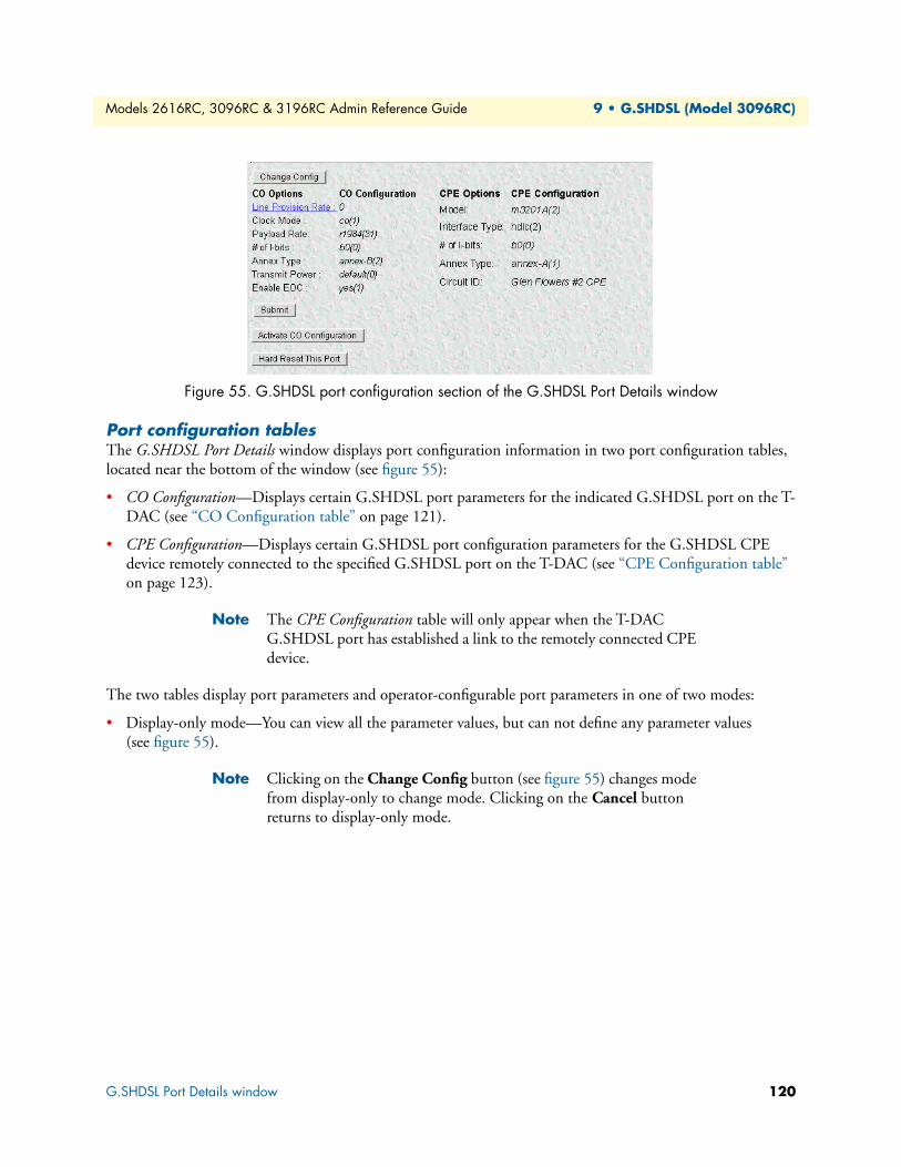
Models 2616RC, 3096RC & 3196RC Admin Reference Guide 9 • G.SHDSL (Model 3096RC)
Figure 55. G.SHDSL port configuration section of the G.SHDSL Port Details window
Port configuration tablesThe G.SHDSL Port Details window displays port configuration information in two port configuration tables, located near the bottom of the window (see figure 55):
• CO Configuration—Displays certain G.SHDSL port parameters for the indicated G.SHDSL port on the T-DAC (see “CO Configuration table” on page 121).
• CPE Configuration—Displays certain G.SHDSL port configuration parameters for the G.SHDSL CPE device remotely connected to the specified G.SHDSL port on the T-DAC (see “CPE Configuration table” on page 123).
Note The CPE Configuration table will only appear when the T-DAC G.SHDSL port has established a link to the remotely connected CPE device.
The two tables display port parameters and operator-configurable port parameters in one of two modes:
• Display-only mode—You can view all the parameter values, but can not define any parameter values (see figure 55).
Note Clicking on the Change Config button (see figure 55) changes mode from display-only to change mode. Clicking on the Cancel button returns to display-only mode.
G.SHDSL Port Details window 120

Models 2616RC, 3096RC & 3196RC Admin Reference Guide 9 • G.SHDSL (Model 3096RC)
Figure 56. G.SHDSL port configuration section in Change mode
• Change mode—You can view all the parameter values and modify the values for some of the parameters (see figure 56). In Change mode, the T-DAC displays a Cancel button along with the Change Config button. Click Cancel to display the tables in display-only mode. In Change mode, clicking on the Change Config button refreshes the display. When you click the Change Config, the T-DAC retrieves parameter values cur-rently stored in DRAM and displays them on the page. Any configurable parameter values entered or selected since you last clicked (submit) will be overwritten with values retrieved from DRAM. When monitoring oper-ating status or statistics, or when defining new values for configurable parameters, use this button to update the display. You can watch any changes take place as they are reflected on the G.SHDSL port status display.
Change Config buttonClick the Change Config button to display the port configuration tables in change mode. In change mode, clicking on the Change Config button refreshes the display. When you click the Change Config, the T-DAC retrieves parameter values currently stored in DRAM and displays them on the page. Any configurable param-eter values entered or selected since you last clicked (submit) will be overwritten with values retrieved from DRAM. When monitoring operating status or statistics, or when defining new values for configurable parame-ters, use this button to update the display. You can watch any changes take place as they are reflected on the G.SHDSL port status display.
Cancel buttonThe Cancel button only appears when the G.SHDSL Port Details page is displayed in change mode. In change mode, the T-DAC displays the Cancel button next to the Change Config button, above the Port Con-figuration tables. To return to display-only mode, click the Cancel button. When you click the Cancel button, the T-DAC will re-display the Port Configuration tables in display-only mode.
CO Configuration tableThe CO Configuration table (see figure 55 on page 120) shows the following parameters:
• Line Provision Rate (gshDSLLineProbeRate)—Display-only. Indicates the recommended line rate calcu-lated by the T-DAC’s Line Probe (an on-board line rate provisioning tool). For more information about the Line Probe, see the section entitled “G.SHDSL Line Provision page”
G.SHDSL Port Details window 121
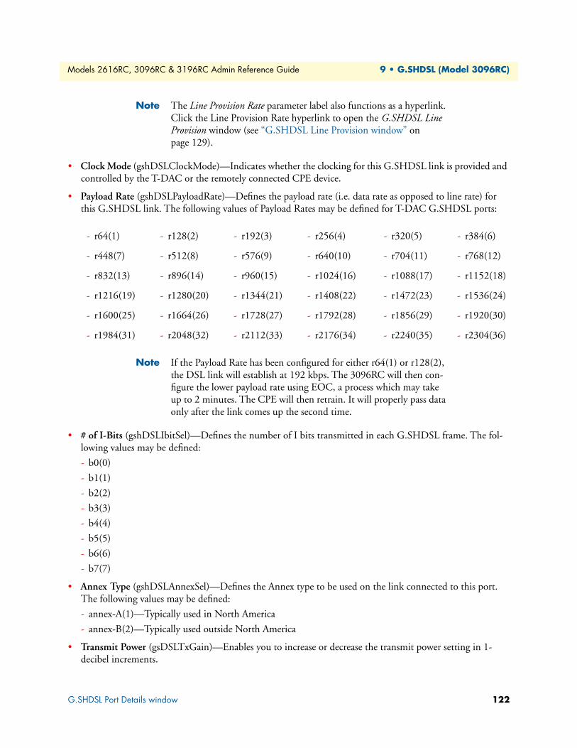
Models 2616RC, 3096RC & 3196RC Admin Reference Guide 9 • G.SHDSL (Model 3096RC)
Note The Line Provision Rate parameter label also functions as a hyperlink. Click the Line Provision Rate hyperlink to open the G.SHDSL Line Provision window (see “G.SHDSL Line Provision window” on page 129).
• Clock Mode (gshDSLClockMode)—Indicates whether the clocking for this G.SHDSL link is provided and controlled by the T-DAC or the remotely connected CPE device.
• Payload Rate (gshDSLPayloadRate)—Defines the payload rate (i.e. data rate as opposed to line rate) for this G.SHDSL link. The following values of Payload Rates may be defined for T-DAC G.SHDSL ports:
Note If the Payload Rate has been configured for either r64(1) or r128(2), the DSL link will establish at 192 kbps. The 3096RC will then con-figure the lower payload rate using EOC, a process which may take up to 2 minutes. The CPE will then retrain. It will properly pass data only after the link comes up the second time.
• # of I-Bits (gshDSLIbitSel)—Defines the number of I bits transmitted in each G.SHDSL frame. The fol-lowing values may be defined:
- b0(0)
- b1(1)
- b2(2)
- b3(3)
- b4(4)
- b5(5)
- b6(6)
- b7(7)
• Annex Type (gshDSLAnnexSel)—Defines the Annex type to be used on the link connected to this port. The following values may be defined:
- annex-A(1)—Typically used in North America
- annex-B(2)—Typically used outside North America
• Transmit Power (gsDSLTxGain)—Enables you to increase or decrease the transmit power setting in 1-decibel increments.
- r64(1) - r128(2) - r192(3) - r256(4) - r320(5) - r384(6)
- r448(7) - r512(8) - r576(9) - r640(10) - r704(11) - r768(12)
- r832(13) - r896(14) - r960(15) - r1024(16) - r1088(17) - r1152(18)
- r1216(19) - r1280(20) - r1344(21) - r1408(22) - r1472(23) - r1536(24)
- r1600(25) - r1664(26) - r1728(27) - r1792(28) - r1856(29) - r1920(30)
- r1984(31) - r2048(32) - r2112(33) - r2176(34) - r2240(35) - r2304(36)
G.SHDSL Port Details window 122

Models 2616RC, 3096RC & 3196RC Admin Reference Guide 9 • G.SHDSL (Model 3096RC)
• Enable EOC (gshDSLEOCEnabled)—Defines whether the T-DAC can modify the remote CPE configura-tion by downloading configurable port parameters to the remotely connected CPE device over the G.SHDSL link. The following values may be defined:
- Yes(1)—Enable remote CPE configuration
- No(0)—Disable remote CPE configuration
CPE Configuration tableThe CPE Configuration Table appears on the right side of the page. The table shows certain G.SHDSL Param-eters for the CPE device remotely connected to the selected G.SHDSL port on the T-DAC. The T-DAC will automatically retrieve the parameter values from the CPE every three minutes and update this table. The table comprises two columns. The column labeled CPE Options shows the parameter names. The column labeled CPE Configuration shows the corresponding current value for each parameter. The table displays the following parameters:
• Model (gsRMModelCode)—Indicates the Patton model number of the remotely connected CPE device. One of the following values will be displayed:
- notKnown(200)
- m3201A(2)
- m3201(3)
- m3241(7)
- m2157(6)
- m2156(5)
- m3086-C(4)
- m3086-D(10)
- m3086-K(8)
- m3086-F(9)
Interface Type (gsRMInterfaceType)—Defines the frame layer protocol the CPE device will use when encap-sulating the data received on the G.SHDSL link for forwarding on another link. One of the following values may be defined:
- hdlc(2)
- atm(1)
# of I-bits (gsRMIbitRate)—Indicates the number of I bits transmitted in each G.SHDSL frame. One of the following values will be displayed:
- b0(0)
- b1(1)
- b2(2)
- b3(3)
- b4(4)
G.SHDSL Port Details window 123
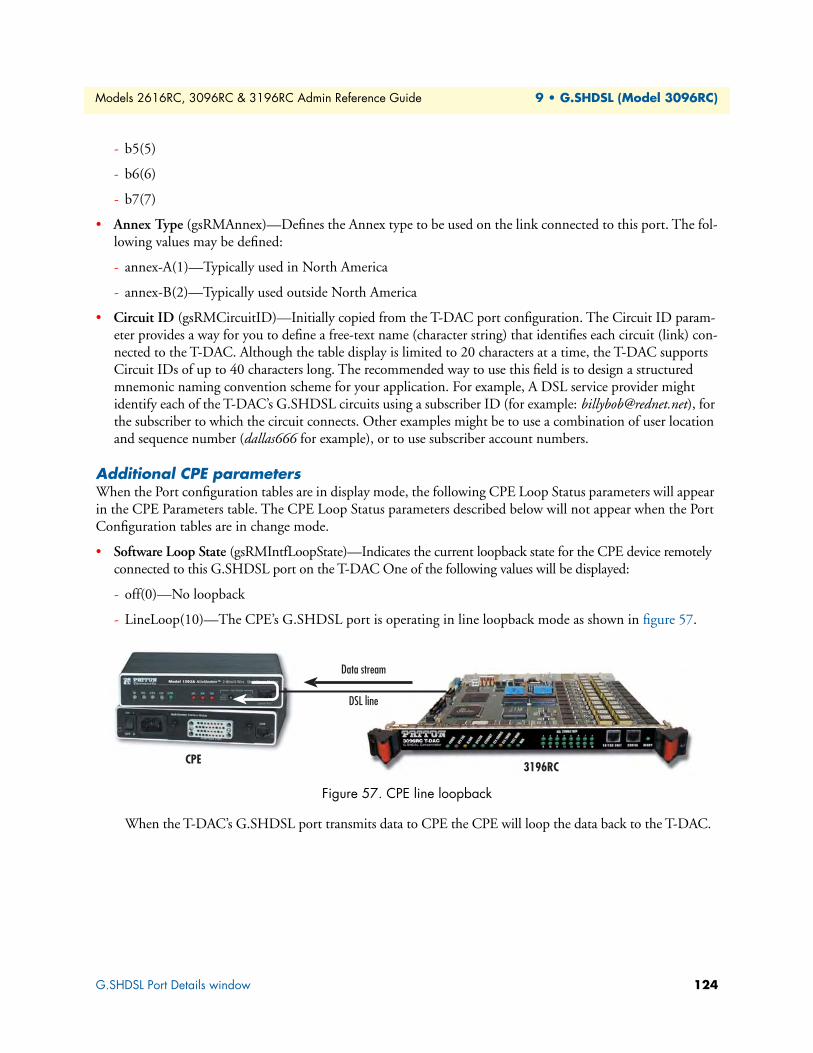
Models 2616RC, 3096RC & 3196RC Admin Reference Guide 9 • G.SHDSL (Model 3096RC)
- b5(5)
- b6(6)
- b7(7)
• Annex Type (gsRMAnnex)—Defines the Annex type to be used on the link connected to this port. The fol-lowing values may be defined:
- annex-A(1)—Typically used in North America
- annex-B(2)—Typically used outside North America
• Circuit ID (gsRMCircuitID)—Initially copied from the T-DAC port configuration. The Circuit ID param-eter provides a way for you to define a free-text name (character string) that identifies each circuit (link) con-nected to the T-DAC. Although the table display is limited to 20 characters at a time, the T-DAC supports Circuit IDs of up to 40 characters long. The recommended way to use this field is to design a structured mnemonic naming convention scheme for your application. For example, A DSL service provider might identify each of the T-DAC’s G.SHDSL circuits using a subscriber ID (for example: [email protected]), for the subscriber to which the circuit connects. Other examples might be to use a combination of user location and sequence number (dallas666 for example), or to use subscriber account numbers.
Additional CPE parameters When the Port configuration tables are in display mode, the following CPE Loop Status parameters will appear in the CPE Parameters table. The CPE Loop Status parameters described below will not appear when the Port Configuration tables are in change mode.
• Software Loop State (gsRMIntfLoopState)—Indicates the current loopback state for the CPE device remotely connected to this G.SHDSL port on the T-DAC One of the following values will be displayed:
- off(0)—No loopback
- LineLoop(10)—The CPE’s G.SHDSL port is operating in line loopback mode as shown in figure 57.
Figure 57. CPE line loopback
When the T-DAC’s G.SHDSL port transmits data to CPE the CPE will loop the data back to the T-DAC.
3196RC
Data stream
CPE
DSL line
G.SHDSL Port Details window 124

Models 2616RC, 3096RC & 3196RC Admin Reference Guide 9 • G.SHDSL (Model 3096RC)
- LocalLoop(11)—The CPE’s G.SHDSL port is operating in local loopback mode as shown in figure 58.
Figure 58. CPE local loopback
When the CPE is in Local Loop mode (see figure 58), the T-DAC can communicate with the CPE for management information. However the CPE cannot receive user data from the T-DAC.
Hardware Loop Status ParametersThe CPE Parameters table will only display Hardware Loop Status parameters when the remotely connected CEP device is a Patton Model 3086. The Hardware Loop Status parameters indicate the state of the Test Modes toggle switches located on the Model 3086 front panel (see figure 59).
Figure 59. Model 3086 front panel test mode switches
• Pattern State (gsRM511State)—Indicates the currently selected position of the right-most Test Mode tog-gle switch on the 3086 front panel. One of the following values will be displayed:
- Idle—No test pattern is in use.
- ser511(1)—511 test pattern
- ser511E(2)—511E test pattern
• Local Loop State (gsRMLLBState)—Indicates whether the 3086 CPE modem is operating in local loop-back mode. Reflects the currently selected position of the left-most Test Mode toggle switch on the 3086 front panel. One of the following values will be displayed:
- Idle—The switch is in the Normal position. The 3086 is not operating in local loopback mode.
- Active—The switch is toggled to the top position. The 3086 is operating in Local Loop mode as shown in figure 58.
• Remote Loop State (gsRMRLBState) Display Only. Indicates whether the 3086 CPE modem is operating in Remote Loopback mode. Reflects the currently selected position of the left-most Test Mode toggle switch on the 3086 front panel. One of the following values will be displayed:
- Idle—The switch is in the Normal position. The 3086 is not operating in remote loopback mode.
3096RCCPE
DSL line
Data stream
G.SHDSL Port Details window 125
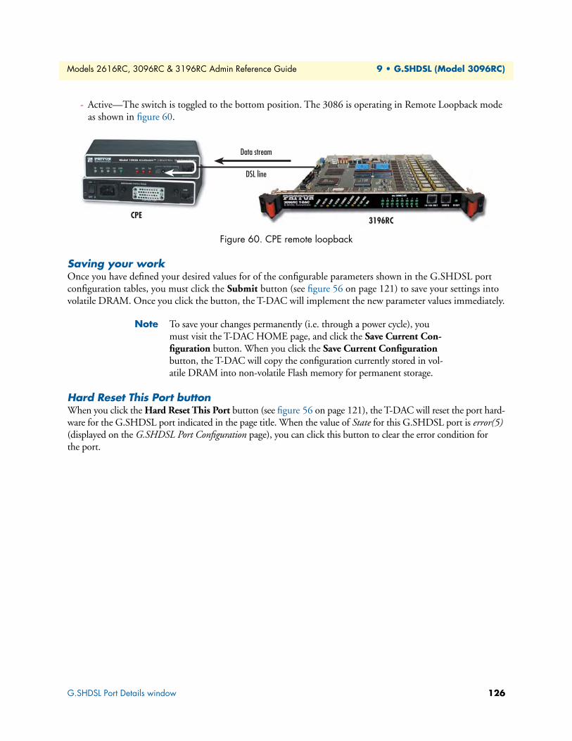
Models 2616RC, 3096RC & 3196RC Admin Reference Guide 9 • G.SHDSL (Model 3096RC)
- Active—The switch is toggled to the bottom position. The 3086 is operating in Remote Loopback mode as shown in figure 60.
Figure 60. CPE remote loopback
Saving your workOnce you have defined your desired values for of the configurable parameters shown in the G.SHDSL port configuration tables, you must click the Submit button (see figure 56 on page 121) to save your settings into volatile DRAM. Once you click the button, the T-DAC will implement the new parameter values immediately.
Note To save your changes permanently (i.e. through a power cycle), you must visit the T-DAC HOME page, and click the Save Current Con-figuration button. When you click the Save Current Configuration button, the T-DAC will copy the configuration currently stored in vol-atile DRAM into non-volatile Flash memory for permanent storage.
Hard Reset This Port buttonWhen you click the Hard Reset This Port button (see figure 56 on page 121), the T-DAC will reset the port hard-ware for the G.SHDSL port indicated in the page title. When the value of State for this G.SHDSL port is error(5) (displayed on the G.SHDSL Port Configuration page), you can click this button to clear the error condition for the port.
3196RC
Data stream
CPE
DSL line
G.SHDSL Port Details window 126

Models 2616RC, 3096RC & 3196RC Admin Reference Guide 9 • G.SHDSL (Model 3096RC)
Figure 61. History of Near-End Performance window
G.SHDSL Port History of Near-End Performance window For each of the T-DAC 16 G.SHDSL ports, the T-DAC collects port error statistics in 15-minute intervals for the most recent 24-hour period. The T-DAC discards port statistics information more than 24 hours old. The G.SHDSL Port History of Near End Performance page (see figure 61) displays a record of the errors counted dur-ing the last 24 hours for the single G.SHDSL port indicated at the top of the window (G.SHDSL Port 1 in figure 61).
Figure 62. Links to and from the G.SHDSL Port History of Near End Performance window
You can reach the G.SHDSL Port History of Near End Performance in one of the following ways (see map in figure 62):
• To display the G.SHDSL Port History of Near End Performance page, on the G.SHDSL Port Details page click the History Details hyperlink.
• To display the G.SHDSL Port History of Near End Performance page, on the System History web manage-ment page in the gshDSL history table, find the column for port you wish to view, then click the History hyperlink for the port you wish to view.
System History
G.SHDSL Port# Details
G.SHDSL Port# Near-End Statistics
G.SHDSL Port History of Near-End Performance window 127

Models 2616RC, 3096RC & 3196RC Admin Reference Guide 9 • G.SHDSL (Model 3096RC)
The G.SHDSL Port History of Near End Performance window also provides hyperlinks for returning to the Sys-tem History and Port Details windows as shown in figure 62 on page 127. The following paragraphs describe the contents of the G.SHDSL Port History of Near End Performance window.
Figure 63. System History Overview window (Model 3096RC shown)
Back To System History Page hyperlinkClick the Back To System History Page link (see figure 61 on page 127) to display the System History Overview window (see figure 63). For a detailed description of the System History Overview window, see chapter 17, “Sys-tem” on page 245.
To Port Details Page hyperlinkClick the To Port Details Page link (see figure 61 on page 127) to display the Port Details window. For a com-plete description of The Port Details window, see section “G.SHDSL Port Details window” on page 113.
Error Statistics tableThe G.SHDSL Port History of Near End Performance window displays G.SHDSL Port error statistics in a table of 96 rows. Each row shows error statistics counted during a 15-minute interval, starting with the most recent 15-minute interval (at the top of the page) and moving chronologically backward as you scroll down the page. The first row (row 1) shows the most recent 15-minute interval, Interval number 1. The last row (row 96) shows the oldest 15-minute interval, Interval number 96. (15 minutes x 96 rows = 24 hours).
• G.SHDSL Port x (gshDSLIntervalNumber)—Indicates the number of the completed 15 minute interval. The Interval Number may range from 1 to 96, where 1 is the most recently completed 15 minute interval and 96 is the least recently completed 15 minute interval.
Columns in the Error Statistics table show the recorded values for the following G.SHDSL port statistics:
• Errored Seconds (ES) (historyESgshDSL)—Indicates the total cumulative number of seconds in which there were one or more FIFO errors on this port during the 15-minute interval.
G.SHDSL Port History of Near-End Performance window 128
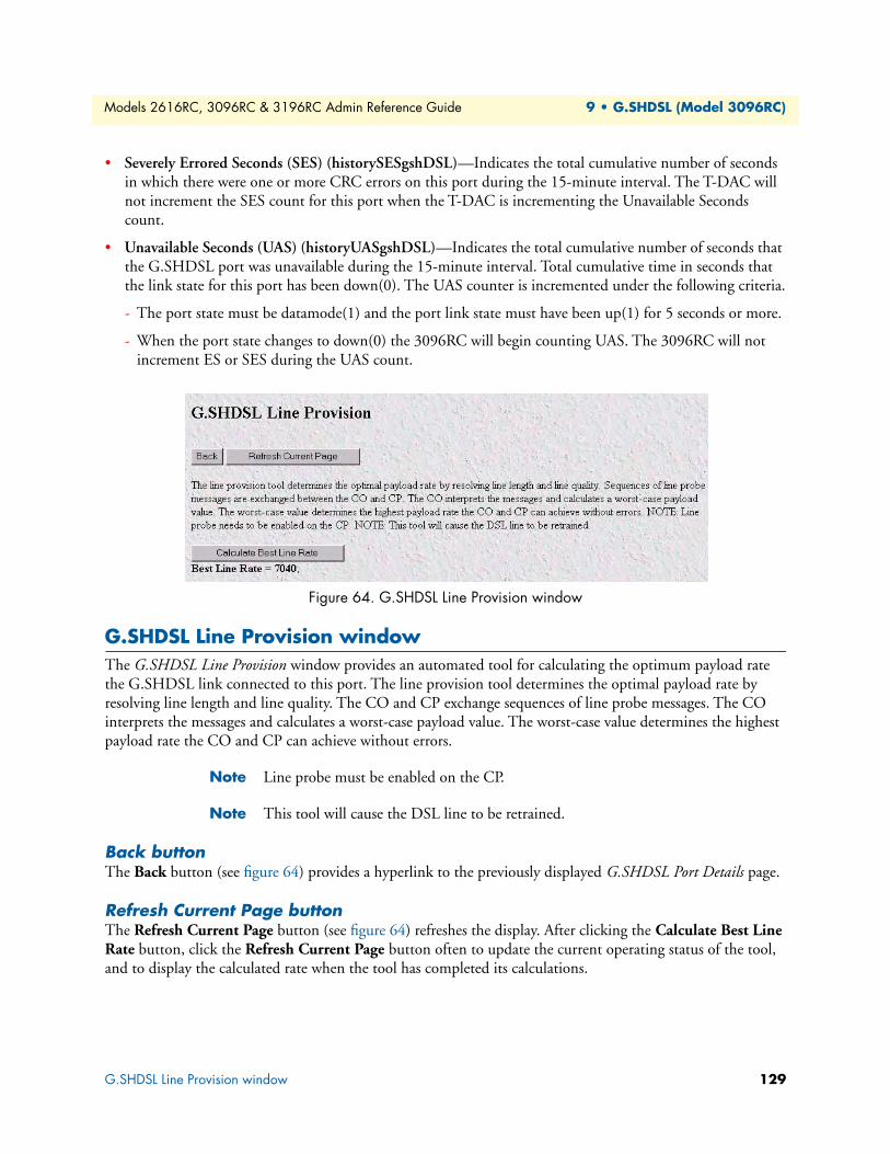
Models 2616RC, 3096RC & 3196RC Admin Reference Guide 9 • G.SHDSL (Model 3096RC)
• Severely Errored Seconds (SES) (historySESgshDSL)—Indicates the total cumulative number of seconds in which there were one or more CRC errors on this port during the 15-minute interval. The T-DAC will not increment the SES count for this port when the T-DAC is incrementing the Unavailable Seconds count.
• Unavailable Seconds (UAS) (historyUASgshDSL)—Indicates the total cumulative number of seconds that the G.SHDSL port was unavailable during the 15-minute interval. Total cumulative time in seconds that the link state for this port has been down(0). The UAS counter is incremented under the following criteria.
- The port state must be datamode(1) and the port link state must have been up(1) for 5 seconds or more.
- When the port state changes to down(0) the 3096RC will begin counting UAS. The 3096RC will not increment ES or SES during the UAS count.
Figure 64. G.SHDSL Line Provision window
G.SHDSL Line Provision windowThe G.SHDSL Line Provision window provides an automated tool for calculating the optimum payload rate the G.SHDSL link connected to this port. The line provision tool determines the optimal payload rate by resolving line length and line quality. The CO and CP exchange sequences of line probe messages. The CO interprets the messages and calculates a worst-case payload value. The worst-case value determines the highest payload rate the CO and CP can achieve without errors.
Note Line probe must be enabled on the CP.
Note This tool will cause the DSL line to be retrained.
Back buttonThe Back button (see figure 64) provides a hyperlink to the previously displayed G.SHDSL Port Details page.
Refresh Current Page buttonThe Refresh Current Page button (see figure 64) refreshes the display. After clicking the Calculate Best Line Rate button, click the Refresh Current Page button often to update the current operating status of the tool, and to display the calculated rate when the tool has completed its calculations.
G.SHDSL Line Provision window 129

Models 2616RC, 3096RC & 3196RC Admin Reference Guide 9 • G.SHDSL (Model 3096RC)
Calculate Best Line Rate buttonClick the Calculate Best Line Rate button (see figure 64) to activate the tool. The T-DAC will compute the best line rate for the link given current conditions. During the procedure, the button will disappear, and the page will transition through the following displays:
WORKING.........idle(0)
WORKING.........training(2)
Once the calculations are completed the button will reappear, and the page will display calculated rate, as shown below:
Best Line Rate = 7040
Cancel buttonClicking the Cancel button cancels line probe operation.
G.SHDSL Line Provision window 130

Chapter 10 iDSL (Model 3196RC)
Chapter contentsIntroduction ........................................................................................................................................................132iDSL Port Configuration window .......................................................................................................................132
iDSL Port Summary Status ...........................................................................................................................133Operator action buttons ................................................................................................................................134iDSL port status ............................................................................................................................................134
Port Number (idslPortNum) ...................................................................................................................134Circuit ID (idslCircuitID) .......................................................................................................................135Current State (idslCurrentState) ..............................................................................................................135
Clearing an error condition ............................................................................................................... 135Color-coded port status indicators ...........................................................................................................136Desired State (idslDesireState) .................................................................................................................136Test Mode (idslTMSelection) .................................................................................................................136Test Pattern (idslPattSelect) ....................................................................................................................138CPE Device (idslRemoteModelCode) .....................................................................................................139CPE Circuit ID .......................................................................................................................................139Saving Your Work ...................................................................................................................................139
iDSL Port Details window...................................................................................................................................140Operator action buttons ................................................................................................................................141iDSL port status and statistics tables .............................................................................................................142
iDSL Port Status table .............................................................................................................................142iDSL Port Statistics table .........................................................................................................................143
CPE information and configuration ....................................................................................................................144CPE information ..........................................................................................................................................144CPE configuration ........................................................................................................................................144
iDSL Near End Performance Interval ..................................................................................................................145Back To System History Page hyperlink .......................................................................................................147To Port Details Page hyperlink .....................................................................................................................147Error Statistics table ......................................................................................................................................147iDSL Alarm Thresholds Per 15 Minute Interval ............................................................................................148
131
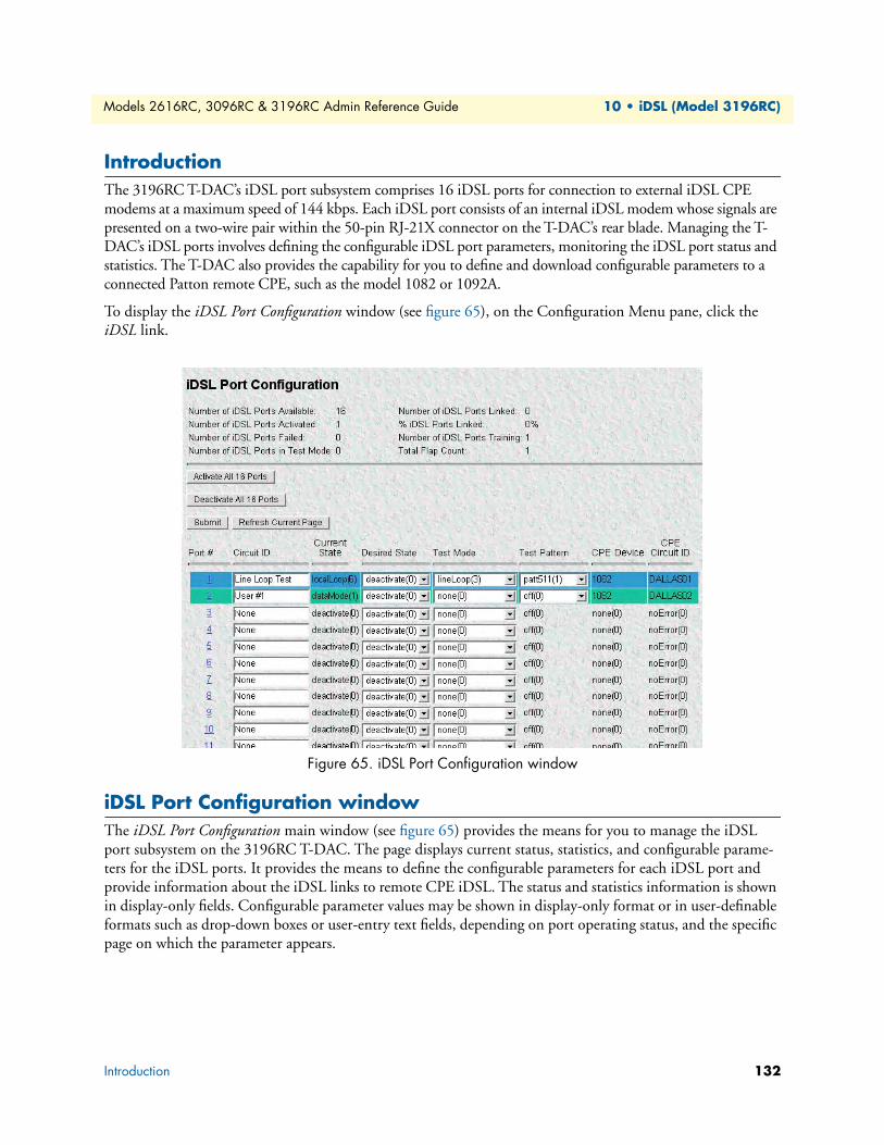
Models 2616RC, 3096RC & 3196RC Admin Reference Guide 10 • iDSL (Model 3196RC)
IntroductionThe 3196RC T-DAC’s iDSL port subsystem comprises 16 iDSL ports for connection to external iDSL CPE modems at a maximum speed of 144 kbps. Each iDSL port consists of an internal iDSL modem whose signals are presented on a two-wire pair within the 50-pin RJ-21X connector on the T-DAC’s rear blade. Managing the T-DAC’s iDSL ports involves defining the configurable iDSL port parameters, monitoring the iDSL port status and statistics. The T-DAC also provides the capability for you to define and download configurable parameters to a connected Patton remote CPE, such as the model 1082 or 1092A.
To display the iDSL Port Configuration window (see figure 65), on the Configuration Menu pane, click the iDSL link.
Figure 65. iDSL Port Configuration window
iDSL Port Configuration windowThe iDSL Port Configuration main window (see figure 65) provides the means for you to manage the iDSL port subsystem on the 3196RC T-DAC. The page displays current status, statistics, and configurable parame-ters for the iDSL ports. It provides the means to define the configurable parameters for each iDSL port and provide information about the iDSL links to remote CPE iDSL. The status and statistics information is shown in display-only fields. Configurable parameter values may be shown in display-only format or in user-definable formats such as drop-down boxes or user-entry text fields, depending on port operating status, and the specific page on which the parameter appears.
Introduction 132
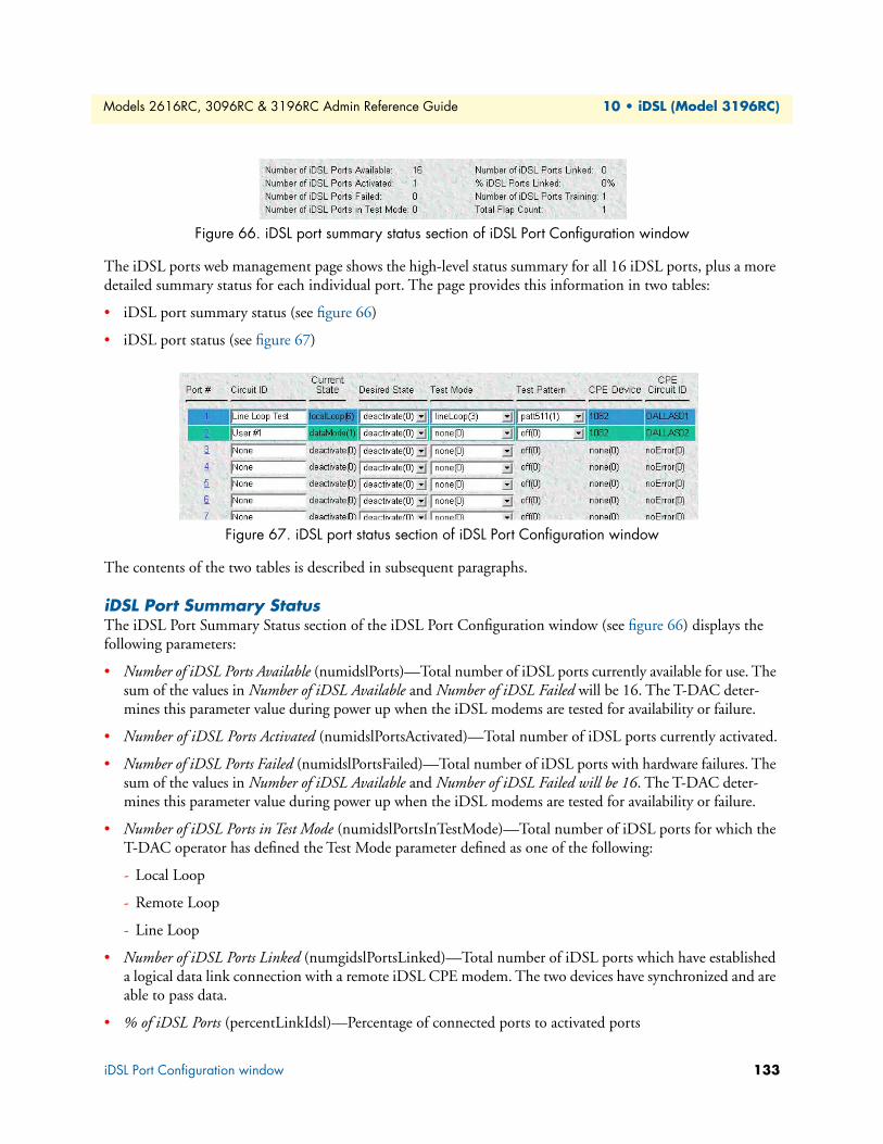
Models 2616RC, 3096RC & 3196RC Admin Reference Guide 10 • iDSL (Model 3196RC)
Figure 66. iDSL port summary status section of iDSL Port Configuration window
The iDSL ports web management page shows the high-level status summary for all 16 iDSL ports, plus a more detailed summary status for each individual port. The page provides this information in two tables:
• iDSL port summary status (see figure 66)
• iDSL port status (see figure 67)
Figure 67. iDSL port status section of iDSL Port Configuration window
The contents of the two tables is described in subsequent paragraphs.
iDSL Port Summary StatusThe iDSL Port Summary Status section of the iDSL Port Configuration window (see figure 66) displays the following parameters:
• Number of iDSL Ports Available (numidslPorts)—Total number of iDSL ports currently available for use. The sum of the values in Number of iDSL Available and Number of iDSL Failed will be 16. The T-DAC deter-mines this parameter value during power up when the iDSL modems are tested for availability or failure.
• Number of iDSL Ports Activated (numidslPortsActivated)—Total number of iDSL ports currently activated.
• Number of iDSL Ports Failed (numidslPortsFailed)—Total number of iDSL ports with hardware failures. The sum of the values in Number of iDSL Available and Number of iDSL Failed will be 16. The T-DAC deter-mines this parameter value during power up when the iDSL modems are tested for availability or failure.
• Number of iDSL Ports in Test Mode (numidslPortsInTestMode)—Total number of iDSL ports for which the T-DAC operator has defined the Test Mode parameter defined as one of the following:
- Local Loop
- Remote Loop
- Line Loop
• Number of iDSL Ports Linked (numgidslPortsLinked)—Total number of iDSL ports which have established a logical data link connection with a remote iDSL CPE modem. The two devices have synchronized and are able to pass data.
• % of iDSL Ports (percentLinkIdsl)—Percentage of connected ports to activated ports
iDSL Port Configuration window 133
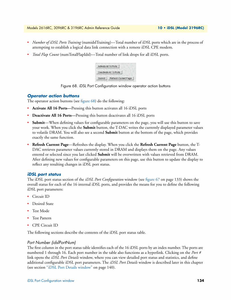
Models 2616RC, 3096RC & 3196RC Admin Reference Guide 10 • iDSL (Model 3196RC)
• Number of iDSL Ports Training (numidslTraining)—Total number of iDSL ports which are in the process of attempting to establish a logical data link connection with a remote iDSL CPE modem.
• Total Flap Count (numTotalFlapIdsl)—Total number of link drops for all iDSL ports.
Figure 68. iDSL Port Configuration window operator action buttons
Operator action buttonsThe operator action buttons (see figure 68) do the following:
• Activate All 16 Ports—Pressing this button activates all 16 iDSL ports
• Deactivate All 16 Ports—Pressing this button deactivates all 16 iDSL ports
• Submit—When defining values for configurable parameters on the page, you will use this button to save your work. When you click the Submit button, the T-DAC writes the currently displayed parameter values to volatile DRAM. You will also see a second Submit button at the bottom of the page, which provides exactly the same function.
• Refresh Current Page—Refreshes the display. When you click the Refresh Current Page button, the T-DAC retrieves parameter values currently stored in DRAM and displays them on the page. Any values entered or selected since you last clicked Submit will be overwritten with values retrieved from DRAM. After defining new values for configurable parameters on this page, use this button to update the display to reflect any resulting changes in iDSL port status.
iDSL port statusThe iDSL port status section of the iDSL Port Configuration window (see figure 67 on page 133) shows the overall status for each of the 16 internal iDSL ports, and provides the means for you to define the following iDSL port parameters:
• Circuit ID
• Desired State
• Test Mode
• Test Pattern
• CPE Circuit ID
The following sections describe the contents of the iDSL port status table.
Port Number (idslPortNum)The first column in the port status table identifies each of the 16 iDSL ports by an index number. The ports are numbered 1 through 16. Each port number in the table also functions as a hyperlink. Clicking on the Port # link opens the iDSL Port Details window, where you can view detailed port status and statistics, and define additional configurable iDSL port parameters. The iDSL Port Details window is described later in this chapter (see section “iDSL Port Details window” on page 140).
iDSL Port Configuration window 134

Models 2616RC, 3096RC & 3196RC Admin Reference Guide 10 • iDSL (Model 3196RC)
Circuit ID (idslCircuitID)Configurable. The Circuit ID parameter provides a way for you to define a free-text name (character string) that identifies each circuit (link) connected to the T-DAC. Although the table display is limited to 20 charac-ters at a time, the T-DAC supports circuit IDs up to 40 characters long. The recommended way to use this field is to design a structured mnemonic naming convention scheme for your application. For example, a DSL service provider might identify each of the T-DAC’s iDSL circuits using a subscriber ID (e.g. [email protected]), for the subscriber to which the circuit connects. Other examples might be to use a combi-nation of user location and sequence number (e.g. dallas25), or to use subscriber account numbers.
Current State (idslCurrentState)The State parameter indicates the current real-time operating state of the port. Possible values are:
• deactivate(0)—Indicates that the port is not currently connected to a remote CPE modem
• initializing(1)—Indicates the port is being prepared for connection to a remote CPE
• reset(2)—Indicates the port is currently in reset mode
• hardwareFailure(3)—Indicates an iDSL port failure
Note See section “Clearing an error condition” on page 135 for informa-tion on resetting a port to clear an error.
• localLoopBack(4)—The port is currently in local loopback mode
• remoteLoopBack(5)—The port is currently in remote loopback mode
• dataMode(6)—The iDSL port is connected to a remote CPE and passing data normally
• lineDown(7)—The T-DAC has detected a break or disconnection in the line connecting to a remote CPE
• lineLoopback(8)—The port is currently in line loopback mode
• testPattern(9)—The T-DAC is currently sending a test pattern on this port
Clearing an error condition. To clear the error condition on an iDSL port, do the following:
1. Go to the Desired State drop down menu for the port, select the Reset option.
2. Click the Submit button at the top of the page.
iDSL Port Configuration window 135
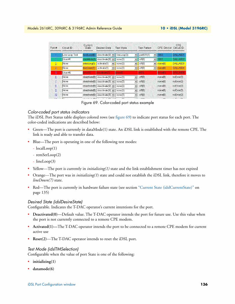
Models 2616RC, 3096RC & 3196RC Admin Reference Guide 10 • iDSL (Model 3196RC)
Figure 69. Color-coded port status example
Color-coded port status indicatorsThe iDSL Port Status table displays colored rows (see figure 69) to indicate port status for each port. The color-coded indications are described below:
• Green—The port is currently in dataMode(1) state. An iDSL link is established with the remote CPE. The link is ready and able to transfer data.
• Blue—The port is operating in one of the following test modes:
- localLoop(1)
- remSerLoop(2)
- lineLoop(3)
• Yellow—The port is currently in initializing(1) state and the link establishment timer has not expired
• Orange—The port was in initializing(1) state and could not establish the iDSL link, therefore it moves to lineDown(7) state.
• Red—The port is currently in hardware failure state (see section “Current State (idslCurrentState)” on page 135)
Desired State (idslDesireState)Configurable. Indicates the T-DAC operator’s current intentions for the port.
• Deactivated(0)—Default value. The T-DAC operator intends the port for future use. Use this value when the port is not currently connected to a remote CPE modem.
• Activated(1)—The T-DAC operator intends the port to be connected to a remote CPE modem for current active use
• Reset(2)—The T-DAC operator intends to reset the iDSL port.
Test Mode (idslTMSelection)Configurable when the value of port State is one of the following:
• initializing(1)
• datamode(6)
iDSL Port Configuration window 136
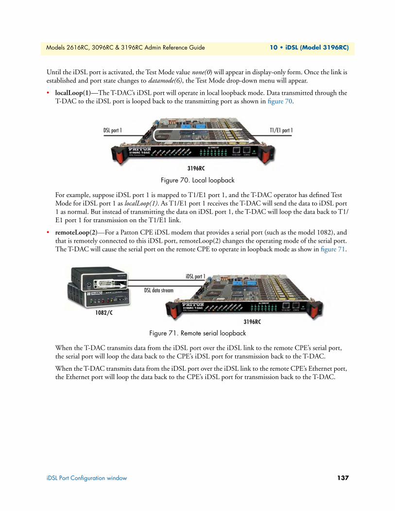
Models 2616RC, 3096RC & 3196RC Admin Reference Guide 10 • iDSL (Model 3196RC)
Until the iDSL port is activated, the Test Mode value none(0) will appear in display-only form. Once the link is established and port state changes to datamode(6), the Test Mode drop-down menu will appear.
• localLoop(1)—The T-DAC’s iDSL port will operate in local loopback mode. Data transmitted through the T-DAC to the iDSL port is looped back to the transmitting port as shown in figure 70.
Figure 70. Local loopback
For example, suppose iDSL port 1 is mapped to T1/E1 port 1, and the T-DAC operator has defined Test Mode for iDSL port 1 as localLoop(1). As T1/E1 port 1 receives the T-DAC will send the data to iDSL port 1 as normal. But instead of transmitting the data on iDSL port 1, the T-DAC will loop the data back to T1/E1 port 1 for transmission on the T1/E1 link.
• remoteLoop(2)—For a Patton CPE iDSL modem that provides a serial port (such as the model 1082), and that is remotely connected to this iDSL port, remoteLoop(2) changes the operating mode of the serial port. The T-DAC will cause the serial port on the remote CPE to operate in loopback mode as show in figure 71.
Figure 71. Remote serial loopback
When the T-DAC transmits data from the iDSL port over the iDSL link to the remote CPE’s serial port, the serial port will loop the data back to the CPE’s iDSL port for transmission back to the T-DAC.
When the T-DAC transmits data from the iDSL port over the iDSL link to the remote CPE’s Ethernet port, the Ethernet port will loop the data back to the CPE’s iDSL port for transmission back to the T-DAC.
3196RC
T1/E1 port 1DSL port 1
iDSL port 1
3196RC
1082/C
DSL data stream
iDSL Port Configuration window 137
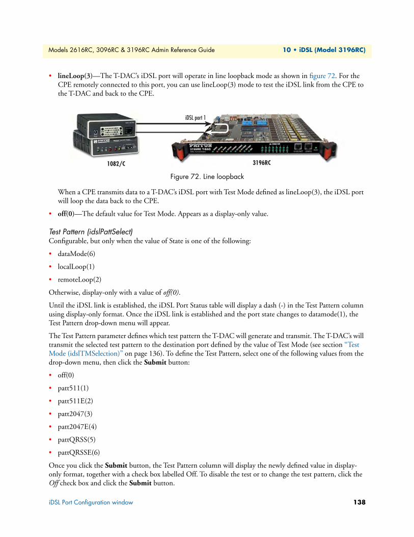
Models 2616RC, 3096RC & 3196RC Admin Reference Guide 10 • iDSL (Model 3196RC)
• lineLoop(3)—The T-DAC’s iDSL port will operate in line loopback mode as shown in figure 72. For the CPE remotely connected to this port, you can use lineLoop(3) mode to test the iDSL link from the CPE to the T-DAC and back to the CPE.
Figure 72. Line loopback
When a CPE transmits data to a T-DAC’s iDSL port with Test Mode defined as lineLoop(3), the iDSL port will loop the data back to the CPE.
• off(0)—The default value for Test Mode. Appears as a display-only value.
Test Pattern (idslPattSelect)Configurable, but only when the value of State is one of the following:
• dataMode(6)
• localLoop(1)
• remoteLoop(2)
Otherwise, display-only with a value of off(0).
Until the iDSL link is established, the iDSL Port Status table will display a dash (-) in the Test Pattern column using display-only format. Once the iDSL link is established and the port state changes to datamode(1), the Test Pattern drop-down menu will appear.
The Test Pattern parameter defines which test pattern the T-DAC will generate and transmit. The T-DAC’s will transmit the selected test pattern to the destination port defined by the value of Test Mode (see section “Test Mode (idslTMSelection)” on page 136). To define the Test Pattern, select one of the following values from the drop-down menu, then click the Submit button:
• off(0)
• patt511(1)
• patt511E(2)
• patt2047(3)
• patt2047E(4)
• pattQRSS(5)
• pattQRSSE(6)
Once you click the Submit button, the Test Pattern column will display the newly defined value in display-only format, together with a check box labelled Off. To disable the test or to change the test pattern, click the Off check box and click the Submit button.
3196RC
iDSL port 1
1082/C
iDSL Port Configuration window 138
Models 2616RC, 3096RC & 3196RC Admin Reference Guide 10 • iDSL (Model 3196RC)
CPE Device (idslRemoteModelCode)Displays model number of Patton remote CPE device connected to the iDSL port, these include:
- none(0),
- model1092(17),
- model1092RC(18),
- model1092A(19),
- model1092ARC(20),
- model1082I(21),
- model1082C(22),
- model1082D(23),
- model1082F(24),
- model1082C-144(25),
- model1082D-144(26),
- model1082I-144(27)
CPE Circuit ID Displays circuit ID of the remote CPE device connected to the iDSL port
Saving Your WorkOnce you have defined your desired values for the configurable parameters shown in the iDSL Port Status table, you must click one of the two Submit Query buttons to save your settings into volatile DRAM. Click-ing either of the Submit Query buttons will save the configurable parameter values displayed for all 16 iDSL ports. Once you click the button, the T-DAC will implement the changes immediately.
Note To save your changes permanently, (i.e. when the T-DAC is powered down) you must visit the T-DAC HOME page, and click the Save Current Configuration button. When you click the Save Current Configuration button, the T-DAC will copy the configuration cur-rently stored in volatile DRAM into non-volatile Flash memory for permanent storage.
iDSL Port Configuration window 139
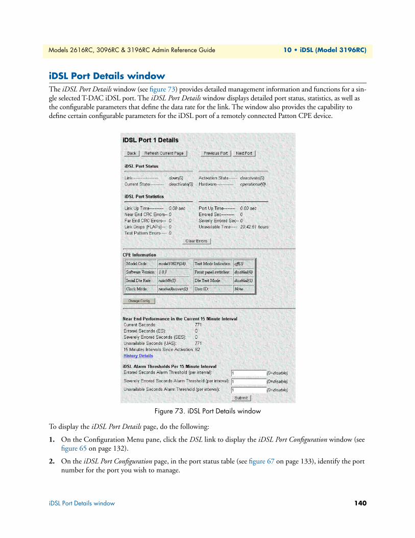
Models 2616RC, 3096RC & 3196RC Admin Reference Guide 10 • iDSL (Model 3196RC)
iDSL Port Details windowThe iDSL Port Details window (see figure 73) provides detailed management information and functions for a sin-gle selected T-DAC iDSL port. The iDSL Port Details window displays detailed port status, statistics, as well as the configurable parameters that define the data rate for the link. The window also provides the capability to define certain configurable parameters for the iDSL port of a remotely connected Patton CPE device.
Figure 73. iDSL Port Details window
To display the iDSL Port Details page, do the following:
1. On the Configuration Menu pane, click the DSL link to display the iDSL Port Configuration window (see figure 65 on page 132).
2. On the iDSL Port Configuration page, in the port status table (see figure 67 on page 133), identify the port number for the port you wish to manage.
iDSL Port Details window 140
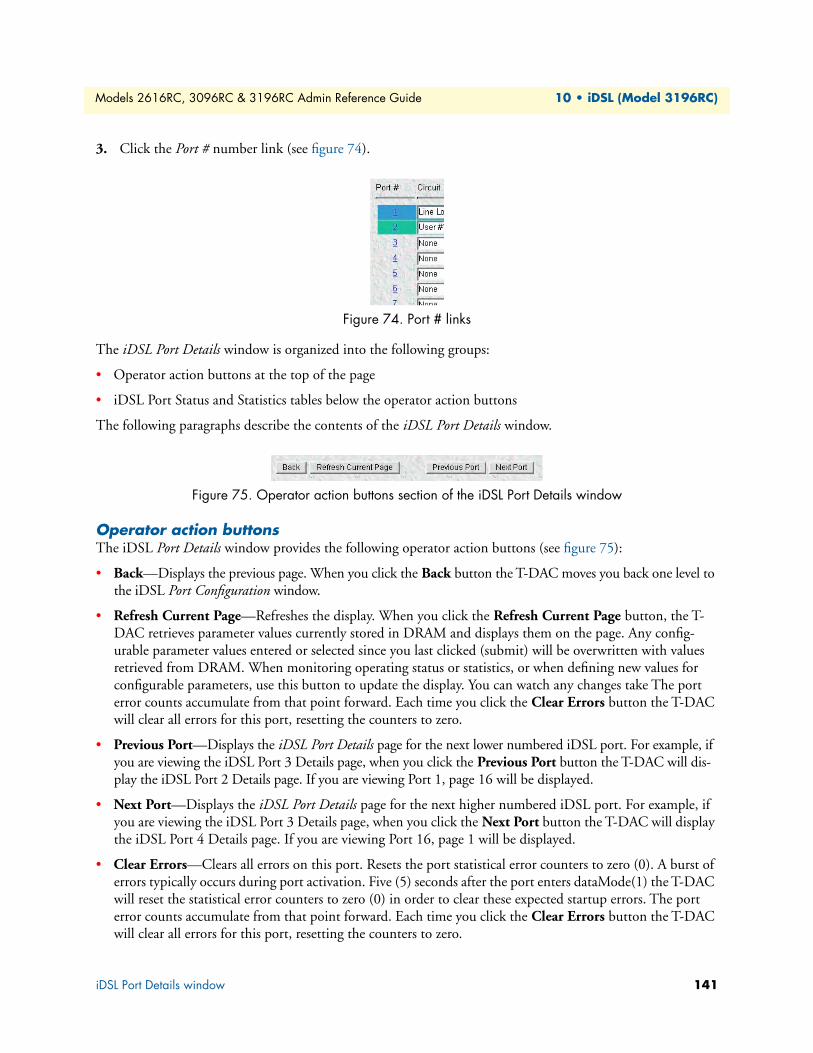
Models 2616RC, 3096RC & 3196RC Admin Reference Guide 10 • iDSL (Model 3196RC)
3. Click the Port # number link (see figure 74).
Figure 74. Port # links
The iDSL Port Details window is organized into the following groups:
• Operator action buttons at the top of the page
• iDSL Port Status and Statistics tables below the operator action buttons
The following paragraphs describe the contents of the iDSL Port Details window.
Figure 75. Operator action buttons section of the iDSL Port Details window
Operator action buttonsThe iDSL Port Details window provides the following operator action buttons (see figure 75):
• Back—Displays the previous page. When you click the Back button the T-DAC moves you back one level to the iDSL Port Configuration window.
• Refresh Current Page—Refreshes the display. When you click the Refresh Current Page button, the T-DAC retrieves parameter values currently stored in DRAM and displays them on the page. Any config-urable parameter values entered or selected since you last clicked (submit) will be overwritten with values retrieved from DRAM. When monitoring operating status or statistics, or when defining new values for configurable parameters, use this button to update the display. You can watch any changes take The port error counts accumulate from that point forward. Each time you click the Clear Errors button the T-DAC will clear all errors for this port, resetting the counters to zero.
• Previous Port—Displays the iDSL Port Details page for the next lower numbered iDSL port. For example, if you are viewing the iDSL Port 3 Details page, when you click the Previous Port button the T-DAC will dis-play the iDSL Port 2 Details page. If you are viewing Port 1, page 16 will be displayed.
• Next Port—Displays the iDSL Port Details page for the next higher numbered iDSL port. For example, if you are viewing the iDSL Port 3 Details page, when you click the Next Port button the T-DAC will display the iDSL Port 4 Details page. If you are viewing Port 16, page 1 will be displayed.
• Clear Errors—Clears all errors on this port. Resets the port statistical error counters to zero (0). A burst of errors typically occurs during port activation. Five (5) seconds after the port enters dataMode(1) the T-DAC will reset the statistical error counters to zero (0) in order to clear these expected startup errors. The port error counts accumulate from that point forward. Each time you click the Clear Errors button the T-DAC will clear all errors for this port, resetting the counters to zero.
iDSL Port Details window 141

Models 2616RC, 3096RC & 3196RC Admin Reference Guide 10 • iDSL (Model 3196RC)
Clicking on the Clear Errors button resets the following counters:
- Near End CRC Errors
- Far End CRC Errors
- Link Drops (FLAPs) (gshDSLFlapCnt)
- Test Pattern Errors (gshDSLPattErrorCnt)
- Errored Sec (gshDSLErroredSec)
- Severely Errored Sec (gshDSLSeverlyErroredSec)
- Unavailable time
Figure 76. iDSL Port Status and Port Statistics sections of the iDSL Port Details window
iDSL port status and statistics tablesThe iDSL Port Details page displays port status and statistics information organized as follows (see figure 76):
• iDSL Port Status table (see section“iDSL Port Status table” on page 142)
• iDSL Port Statistics table (see section “iDSL Port Statistics table” on page 143)
The following sections describe the contents of each table.
iDSL Port Status tableThe iDSL Port Status table displays the current values of the following iDSL port parameters:
• Link (idslLinkUp)—Indicates the current state of the iDSL link. One of the following values will be displayed:
- up(1)
- down(0)
• Current State (idslCurrentState):
- deactivate(0)
- initializing(1)
- reset(2)
- hardwareFailure(3)
iDSL Port Details window 142
Models 2616RC, 3096RC & 3196RC Admin Reference Guide 10 • iDSL (Model 3196RC)
- localLoopBack(4)
- remoteLoopBack(5)
- dataMode(6)
- lineDown(7)
- lineLoopback(8)
- testPattern(9)
• Activation State (idslActivationState)—The operating software for each iDSL port includes a module called the Activation State Manager (ASM). The Activation State Info table provides information about the cur-rent software state for the port. The current values of the following iDSL port parameters are shown in dis-play-only format:
- deactivate(0)
- activate(1)
• Hardware (idslHardwareFail)—Indicates the current overall state of the iDSL port hardware, i.e. the pres-ence or absence of a hardware error condition. One of the following values will be displayed:
- failed(1)
- operational(0)
Note The Near End Performance window which provides a record of errors counted on this port during the last 24 hours in 15-minute intervals (see section “iDSL Near End Performance Interval” on page 145 for more information).
iDSL Port Statistics tableThe iDSL Port Statistics table displays the current values of the following iDSL port statistics variables:
• Link Up-Time (idslUpTimer)—Total Length of time in days:hours:minutes:seconds since the link state for this port last changed to up. This value is reset when the link goes down.
• Near End CRC Errors (idslNebeCounter)—Near end CRC error counter.
• Far End CRC (idslFebeCounter)—Far end CRC error counter
• Link Drops (FLAPs)(idslFlapCounter)—Total number of times the iDSL Port flap (disconnected) since the counter was last reset.
• Port Up-Time (idslCurrentSecond)—The current seconds in the current interval that the iDSL Port has been up.
• Test Pattern Errors (idslPatternErrors)—The total cumulative number of test pattern errors detected on this port since the counter was last reset.
• Errored Seconds (idslErrSecond)—The total cumulative number of seconds in which there were one or more errors on this port since the counter was last reset.
• Severely Errored Seconds (idslSevErrSecond)—The total cumulative number of seconds in which there were one or more CRC errors on this port since the counter was last reset.
iDSL Port Details window 143
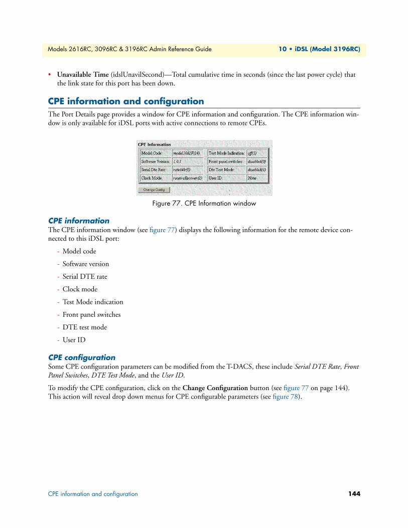
Models 2616RC, 3096RC & 3196RC Admin Reference Guide 10 • iDSL (Model 3196RC)
• Unavailable Time (idslUnavilSecond)—Total cumulative time in seconds (since the last power cycle) that the link state for this port has been down.
CPE information and configurationThe Port Details page provides a window for CPE information and configuration. The CPE information win-dow is only available for iDSL ports with active connections to remote CPEs.
Figure 77. CPE Information window
CPE information The CPE information window (see figure 77) displays the following information for the remote device con-nected to this iDSL port:
- Model code
- Software version
- Serial DTE rate
- Clock mode
- Test Mode indication
- Front panel switches
- DTE test mode
- User ID
CPE configuration Some CPE configuration parameters can be modified from the T-DACS, these include Serial DTE Rate, Front Panel Switches, DTE Test Mode, and the User ID.
To modify the CPE configuration, click on the Change Configuration button (see figure 77 on page 144). This action will reveal drop down menus for CPE configurable parameters (see figure 78).
CPE information and configuration 144

Models 2616RC, 3096RC & 3196RC Admin Reference Guide 10 • iDSL (Model 3196RC)
Figure 78. CPE configurable parameters window
• Serial Rate—Select from the following:
- rate19-2k(0) for serial rate of 19200 bps
- rate32k(1) for serial rate of 32000 bps
- rate56k(1) for serial rate of 56000 bps
- rate64k(1) for serial rate of 64000 bps
- rate128k(1) for serial rate of 128000 bps
- rate144k(1) for serial rate of 144000 bps
• Front Panel Switches—Front panel switches at the CPE can be enabled or disabled.
- dissabled(0)—CPE front panel switches disabled
- enabled(1)—CPE front panel switches enabled.
• DTE Test Mode—CPE test mode can be enabled or disabled
- disabled(0)—CPE cannot initiate or respond to test patterns.
- enabled(1)—CPE can initiate or respond to test patterns
• User ID—Enter new user ID for remote CPE
To activate changes made to this window, click on the Submit button. Otherwise, click on the Cancel button to cancel changes.
iDSL Near End Performance IntervalFor each of the T-DAC 16 iDSL ports, the T-DAC collects port error statistics in 15-minute intervals for the most recent 24-hour period. The Port Details page displays port error statistics for the current 15 minute inter-val this statistics include:
- Current Seconds
- Errored Seconds (ES)
- Severely Errored Seconds (SES)
- Unavailable Seconds (UAS)
iDSL Near End Performance Interval 145

Models 2616RC, 3096RC & 3196RC Admin Reference Guide 10 • iDSL (Model 3196RC)
- 15 Minutes Intervals Since Activation
Figure 79. Near End Performance in the Current 15 minute Interval
The T-DAC discards port statistics information more than 24 hours old. The iDSL Port History of Near End Performance page (see figure 79) displays a record of the errors counted during the last 24 hours for the single iDSL port indicated at the top of the window (iDSL Port 1 in figure 80).
Figure 80. iDSL Port History of Near End Performance window
You can reach the iDSL Port History of Near End Performance in the following ways:
• To display the iDSL Port History of Near End Performance page, on the iDSL Port Details page click the His-tory Details hyperlink.
• To display the iDSL Port History of Near End Performance page, on the System History web management page in the iDSL history table, find the column for port you wish to view, then click the History hyperlink for the port you wish to view.
The iDSL Port History of Near End Performance window also provides hyperlinks for returning to the System History and Port Details windows as shown in figure 80. The following paragraphs describe the contents of the iDSL Port History of Near End Performance window.
iDSL Near End Performance Interval 146
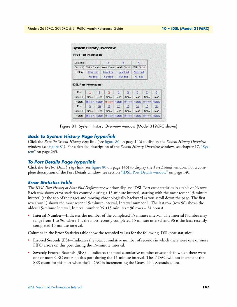
Models 2616RC, 3096RC & 3196RC Admin Reference Guide 10 • iDSL (Model 3196RC)
Figure 81. System History Overview window (Model 3196RC shown)
Back To System History Page hyperlinkClick the Back To System History Page link (see figure 80 on page 146) to display the System History Overview window (see figure 81). For a detailed description of the System History Overview window, see chapter 17, “Sys-tem” on page 245.
To Port Details Page hyperlinkClick the To Port Details Page link (see figure 80 on page 146) to display the Port Details window. For a com-plete description of the Port Details window, see section “iDSL Port Details window” on page 140.
Error Statistics tableThe iDSL Port History of Near End Performance window displays iDSL Port error statistics in a table of 96 rows. Each row shows error statistics counted during a 15-minute interval, starting with the most recent 15-minute interval (at the top of the page) and moving chronologically backward as you scroll down the page. The first row (row 1) shows the most recent 15-minute interval, Interval number 1. The last row (row 96) shows the oldest 15-minute interval, Interval number 96. (15 minutes x 96 rows = 24 hours).
• Interval Number—Indicates the number of the completed 15 minute interval. The Interval Number may range from 1 to 96, where 1 is the most recently completed 15 minute interval and 96 is the least recently completed 15 minute interval.
Columns in the Error Statistics table show the recorded values for the following iDSL port statistics:
• Errored Seconds (ES)—Indicates the total cumulative number of seconds in which there were one or more FIFO errors on this port during the 15-minute interval.
• Severely Errored Seconds (SES) —Indicates the total cumulative number of seconds in which there were one or more CRC errors on this port during the 15-minute interval. The T-DAC will not increment the SES count for this port when the T-DAC is incrementing the Unavailable Seconds count.
iDSL Near End Performance Interval 147
Models 2616RC, 3096RC & 3196RC Admin Reference Guide 10 • iDSL (Model 3196RC)
• Unavailable Seconds (UAS) —Indicates the total cumulative number of seconds that the iDSL port was unavailable during the 15-minute interval. Total cumulative time in seconds that the link state for this port has been down(0). The UAS counter is incremented under the following criteria.
- The port state must be datamode and the port link state must have been up for 5 seconds or more.
- When the port state changes to down the 3196RC will begin counting UAS. The 3196RC will not incre-ment ES or SES during the UAS count.
iDSL Alarm Thresholds Per 15 Minute Interval The iDSL threshold per 15 minute interval allows the user to specify the number of errored seconds and unavailable seconds for which an alarm condition will be triggered.
• Errored Seconds Alarm Threshold (per interval)—Enter a number of errored seconds that will trigger an alarm.
• Severely Errored Seconds Alarm Threshold (per interval) - Enter a number of errored seconds that will trig-ger an alarm.
• Unavailable Seconds Alarm Threshold (per interval) - Enter a number of unavailable seconds that will trig-ger an alarm.
iDSL Near End Performance Interval 148

Chapter 11 In-band management
Chapter contentsOverview .............................................................................................................................................................151Introduction ........................................................................................................................................................151
When to use in-band management ................................................................................................................152In-Band Management Overview window ............................................................................................................153Defining a T1/E1 Management Channel ............................................................................................................154
Example 1: T1/E1 Frame Relay Management Channel .................................................................................156Deleting the T1/E1 management channel ...............................................................................................157
Example 2: T1/E1 Routed PPP Management Channel .................................................................................158Deleting the T1/E1 management channel ...............................................................................................159
Example 3: T1/E1 Bridged PPP Management Channel ................................................................................159Deleting the T1/E1 management channel ...............................................................................................160
Defining a Chassis (H.110) Management Channel..............................................................................................160PPP-IPCP Chassis Management Channel............................................................................................................161
Name ............................................................................................................................................................161IP Address (sysMgmtIpAddress) ....................................................................................................................161Direction ......................................................................................................................................................161Port ...............................................................................................................................................................161TimeSlot .......................................................................................................................................................162Default Gateway (sysMgmtDefaultGateway) ................................................................................................162Example 1: Routed PPP (IPCP) Chassis Management Channel ....................................................................164
Define button .........................................................................................................................................164Example 2: Bridged PPP (BCP) Chassis Management Channel ....................................................................165
Defining a G.SHDSL Management Channel ......................................................................................................167IP Addresses—IPCP & BCP .........................................................................................................................167
Configure the Model 3096RC for a G.SHDSL in-band management channel ..............................................168Example 1: Configuring a BCP bridged G.SHDSL link for management traffic only ...................................169
Configure Model 3086 for an in-band management channel ..................................................................1703096RC G.SHDSL Management Link Status .........................................................................................171
Example 2: Configuring an IPCP routed G.SHDSL link for management traffic only ..................................172Configure Model 3086 for an in-band management channel ..................................................................1733096RC G.SHDSL Management Link Status .........................................................................................174
The Chassis Management Channel statistics page................................................................................................176Connection ID (sysMgmtConnectionID) .....................................................................................................176Deleting an H.110 in-band management channel .........................................................................................176Connection Details .......................................................................................................................................177
IP Address (sysMgmtIpAddress) ..............................................................................................................177Status (sysMgmtStatus) ...........................................................................................................................177TX Port (sysMgmtPortTx) ......................................................................................................................177Tx TimeSlot (sysMgmtSlotTx) ...............................................................................................................177
149

Models 2616RC, 3096RC & 3196RC Admin Reference Guide 11 • In-band management
Rx Port (sysMgmtPortRx) .......................................................................................................................177Rx TimeSlot (sysMgmtSlotRx) ................................................................................................................177
HDLC Statistics ...........................................................................................................................................177LINK Resets (sysMgmtResets) ................................................................................................................177Transmit Octets (sysMgmtTxOctets) ......................................................................................................177Transmit Frames (sysMgmtTxMessageEnds) ..........................................................................................177Receive Octets (sysMgmtRxOctets) .........................................................................................................177Receive Frames (sysMgmtRxMessageEnds) .............................................................................................178Receive Frames Too Long (sysMgmtRxPacketTooLong) ........................................................................178Receive Bad CRCs (sysMgmtRxBadCrc) .................................................................................................178Receive Invalid Frames (sysMgmtRxInvalidFrame) .................................................................................178Receive No Buffers Available (sysMgmtRxNoBufferAvailable) ................................................................178
IP Routing table modifications ............................................................................................................................178Recommended troubleshooting if the link does not come UP .............................................................................178
150

Models 2616RC, 3096RC & 3196RC Admin Reference Guide 11 • In-band management
OverviewThis chapter describes how to configure in-band management channels. The “Introduction” section describes the architecture and use of in-band management channels. Succeeding sections describe the three types of in-band management channels (each section includes examples that will help you understand and use in-band management channels in your network system).
The first type of in-band management channel is described in section “Defining a T1/E1 Management Chan-nel” on page 154. The following examples of T1/E1 management channels are included:
• Using a Frame Relay channel over the T1/E1 port
• Creating a bridged PPP channel over T1/E1
• Implementing a routed PPP channel
The second type is described in section “Defining a Chassis (H.110) Management Channel” on page 160. The following two examples are included:
• A routed PPP (IPCP) chassis management channel
• A bridged PPP (BCP) chassis management channel
The third and last type is described in section “Defining a G.SHDSL Management Channel” on page 167. The following examples connect via a Patton Model 3086 over a G.SHDSL link in two configurations:
• A bridged PPP (BCP) management channel
• A routed PPP (IPCP) in-band channel
IntroductionThe Models 3096RC G.SHDSL, 3196RC iDSL, and 2616RC T1/E1 T-DACs offer in-band management over Frame Relay or PPP (point-to-point protocol). Management channels may be created over a T1/E1 WAN port, a G.SHDSL WAN port, or the Chassis Management Channels. The remote management channel is for access from a remote management station via the T1/E1 or G.SHDSL WAN port into the T-DAC. The Chas-sis Management Channels are management links between cards within the same ForeFront chassis.
By using a combination of remote management channels and Chassis Management Channels, all the cards in one chassis and multiple chassis can be managed via one T1/E1 or G.SHDSL WAN link from a remote man-agement station, which may simply be a PC with a standard browser like Netscape or Internet Explorer.
The remote management channels may be configured for either Frame Relay or PPP using a single or multiple DS0 time slots in the T1/E1 or G.SHDSL WAN port. Each Chassis Management Channel uses one time slot in each direction. Further details are provided below in the section describing how to define a Chassis Management Channel.
Figure 82 is a graphical example with the management station accessing the ForeFront chassis through a T1/E1 or G.SHDSL WAN port via a TDM network. T-DAC_2 and T-DAC_3 have in-band management paths with Chassis Management Channels in a star topology. T-DAC_1 is the hub of the star.
Overview 151

Models 2616RC, 3096RC & 3196RC Admin Reference Guide 11 • In-band management
Figure 82. In-band management
This chapter gives instructions on how to define Frame Relay and PPP remote in-band management channels with examples. Secondly the creation of Chassis Management Channels are explained in detail for PPP IPCP and BCP links. Because bringing a link UP is only part of the process in configuring in-band management channels, the IP routing table is discussed so IP continuity is provided. If trouble occurs, particularly if the channel does not come UP, a listing of the most common causes is included.
When to use in-band managementBecause the Model 6511 Matrix Switch provides two chassis Ethernet buses that enable you to access all the cards in a ForeFront chassis, Chassis Management Channels are not needed for configurations when a Matrix Switch is installed. In-band management is useful in configurations that do not have a Matrix Switch.
Note The Model 6676 ForeFront chassis comprises two logically separate segments that behave like two separate chassis from the perspective of in-band management channels. Segment R (the first 8 slots) func-tions independently from Segment L (the last 9 slots) in terms of in-band management. The chassis Ethernet buses in the Model 6676 are similarly independent between Segment R and L. So there are two chassis Ethernet buses in each segment of the 6676.
Defined ChassisManagement Channel
In-band management trafficT1/E1 orG.SHDSL port
TDMNetwork
T-DAC 1 T-DAC 2
Managementworkstation
ManagementServices
ManagementServices
TDM Mid-plane bus
T-DAC N
ManagementServices
Introduction 152
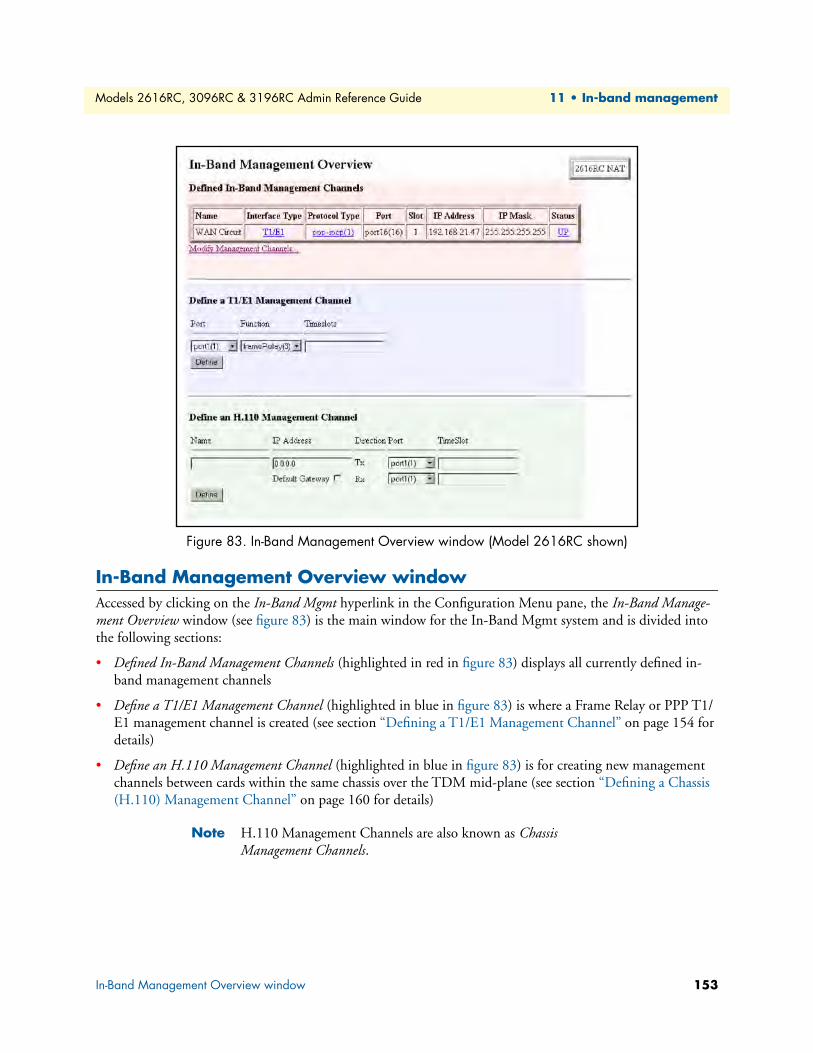
Models 2616RC, 3096RC & 3196RC Admin Reference Guide 11 • In-band management
Figure 83. In-Band Management Overview window (Model 2616RC shown)
In-Band Management Overview windowAccessed by clicking on the In-Band Mgmt hyperlink in the Configuration Menu pane, the In-Band Manage-ment Overview window (see figure 83) is the main window for the In-Band Mgmt system and is divided into the following sections:
• Defined In-Band Management Channels (highlighted in red in figure 83) displays all currently defined in-band management channels
• Define a T1/E1 Management Channel (highlighted in blue in figure 83) is where a Frame Relay or PPP T1/E1 management channel is created (see section “Defining a T1/E1 Management Channel” on page 154 for details)
• Define an H.110 Management Channel (highlighted in blue in figure 83) is for creating new management channels between cards within the same chassis over the TDM mid-plane (see section “Defining a Chassis (H.110) Management Channel” on page 160 for details)
Note H.110 Management Channels are also known as Chassis Management Channels.
In-Band Management Overview window 153

Models 2616RC, 3096RC & 3196RC Admin Reference Guide 11 • In-band management
Defining a T1/E1 Management ChannelA T1/E1 in-band management channel can be created over any active T1/E1 WAN port. The following exam-ples show how to define a T1/E1 management channel:
• Frame Relay Management channel over the T1/E1 link.
• A routed PPP management channel (IPCP).
• A bridged PPP management channel (BCP).
While the T1/E1 port does not need to be connected in order to define the T1/E1 management channel, the Frame Relay or PPP channel cannot come “UP” until there is a proper connection on the other end of the T1/E1 port.
Figure 84. Define a T1/E1 Management Channel window showing frameRelay(3) and ppp(5) menu options
Prior to defining the channel, verify that the desired T1/E1 port is already activated by going to the T1/E1 Link subsystem.
The following parameters are required to initially configure a T1/E1 management channel:
• Port—This parameter refers to the T1/E1 ports on this card. Select the T1/E1 link desired for the in-band management channel. To see how many and which T1/E1 ports are available, click on the T1/E1 Link hyperlink in the Menu. Be sure that the port is already activated for operation. You do not need to configure the Channel Assignment….
• Function—The two functions are:
- frameRelay(3).
- ppp(5) for IPCP or BCP links (IPCP are for routed links and BCP for bridged links).
• Timeslots—Prior to entering the DS0’s (timeslots), go to the “DS0 Mapping” page to be sure you are not using DS0’s already configured for mapping.
Click on the Define button to create a link.
Note In this section for defining T1/E1 management channels, “timeslots” refer to voice channels. For both Frame Relay and PPP management channels over an E1, you may select a single slot or a group of slots between 1-30. Entering 1-30 will select all slots, except for timeslot 16, which does not act as a voice channel because it is used for signal-ing information.
Defining a T1/E1 Management Channel 154
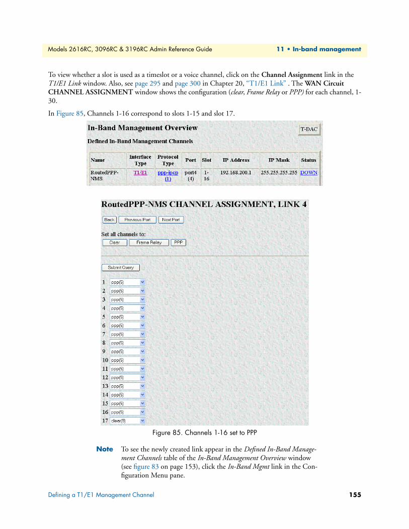
Models 2616RC, 3096RC & 3196RC Admin Reference Guide 11 • In-band management
To view whether a slot is used as a timeslot or a voice channel, click on the Channel Assignment link in the T1/E1 Link window. Also, see page 295 and page 300 in Chapter 20, “T1/E1 Link” . The WAN Circuit CHANNEL ASSIGNMENT window shows the configuration (clear, Frame Relay or PPP) for each channel, 1-30.
In Figure 85, Channels 1-16 correspond to slots 1-15 and slot 17.
Figure 85. Channels 1-16 set to PPP
Note To see the newly created link appear in the Defined In-Band Manage-ment Channels table of the In-Band Management Overview window (see figure 83 on page 153), click the In-Band Mgmt link in the Con-figuration Menu pane.
Defining a T1/E1 Management Channel 155
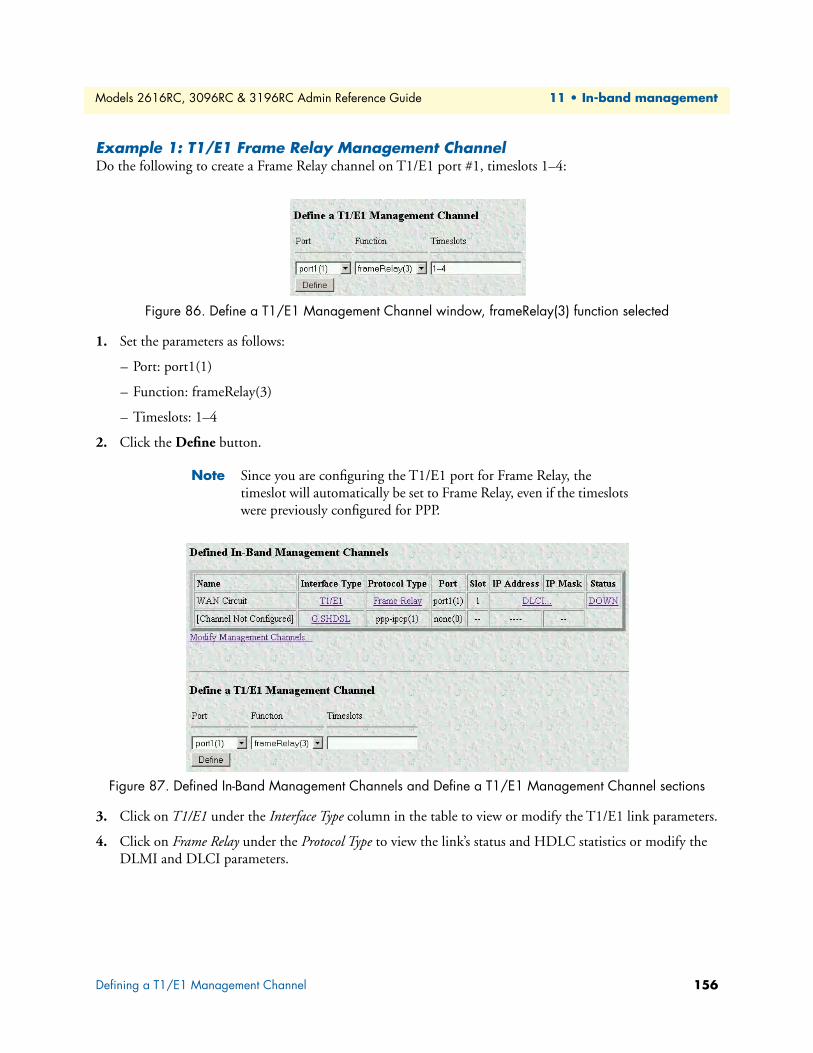
Models 2616RC, 3096RC & 3196RC Admin Reference Guide 11 • In-band management
Example 1: T1/E1 Frame Relay Management ChannelDo the following to create a Frame Relay channel on T1/E1 port #1, timeslots 1–4:
Figure 86. Define a T1/E1 Management Channel window, frameRelay(3) function selected
1. Set the parameters as follows:
– Port: port1(1)
– Function: frameRelay(3)
– Timeslots: 1–4
2. Click the Define button.
Note Since you are configuring the T1/E1 port for Frame Relay, the timeslot will automatically be set to Frame Relay, even if the timeslots were previously configured for PPP.
Figure 87. Defined In-Band Management Channels and Define a T1/E1 Management Channel sections
3. Click on T1/E1 under the Interface Type column in the table to view or modify the T1/E1 link parameters.
4. Click on Frame Relay under the Protocol Type to view the link’s status and HDLC statistics or modify the DLMI and DLCI parameters.
Defining a T1/E1 Management Channel 156
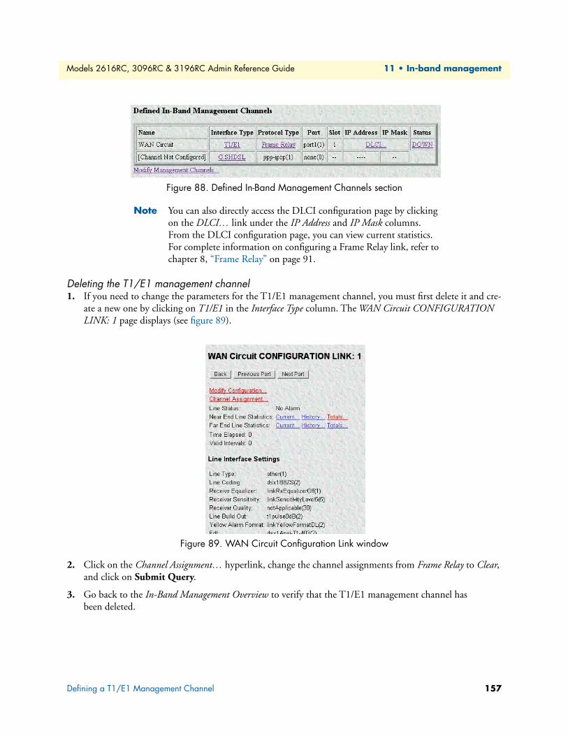
Models 2616RC, 3096RC & 3196RC Admin Reference Guide 11 • In-band management
Figure 88. Defined In-Band Management Channels section
Note You can also directly access the DLCI configuration page by clicking on the DLCI… link under the IP Address and IP Mask columns. From the DLCI configuration page, you can view current statistics. For complete information on configuring a Frame Relay link, refer to chapter 8, “Frame Relay” on page 91.
Deleting the T1/E1 management channel1. If you need to change the parameters for the T1/E1 management channel, you must first delete it and cre-
ate a new one by clicking on T1/E1 in the Interface Type column. The WAN Circuit CONFIGURATION LINK: 1 page displays (see figure 89).
Figure 89. WAN Circuit Configuration Link window
2. Click on the Channel Assignment… hyperlink, change the channel assignments from Frame Relay to Clear, and click on Submit Query.
3. Go back to the In-Band Management Overview to verify that the T1/E1 management channel has been deleted.
Defining a T1/E1 Management Channel 157
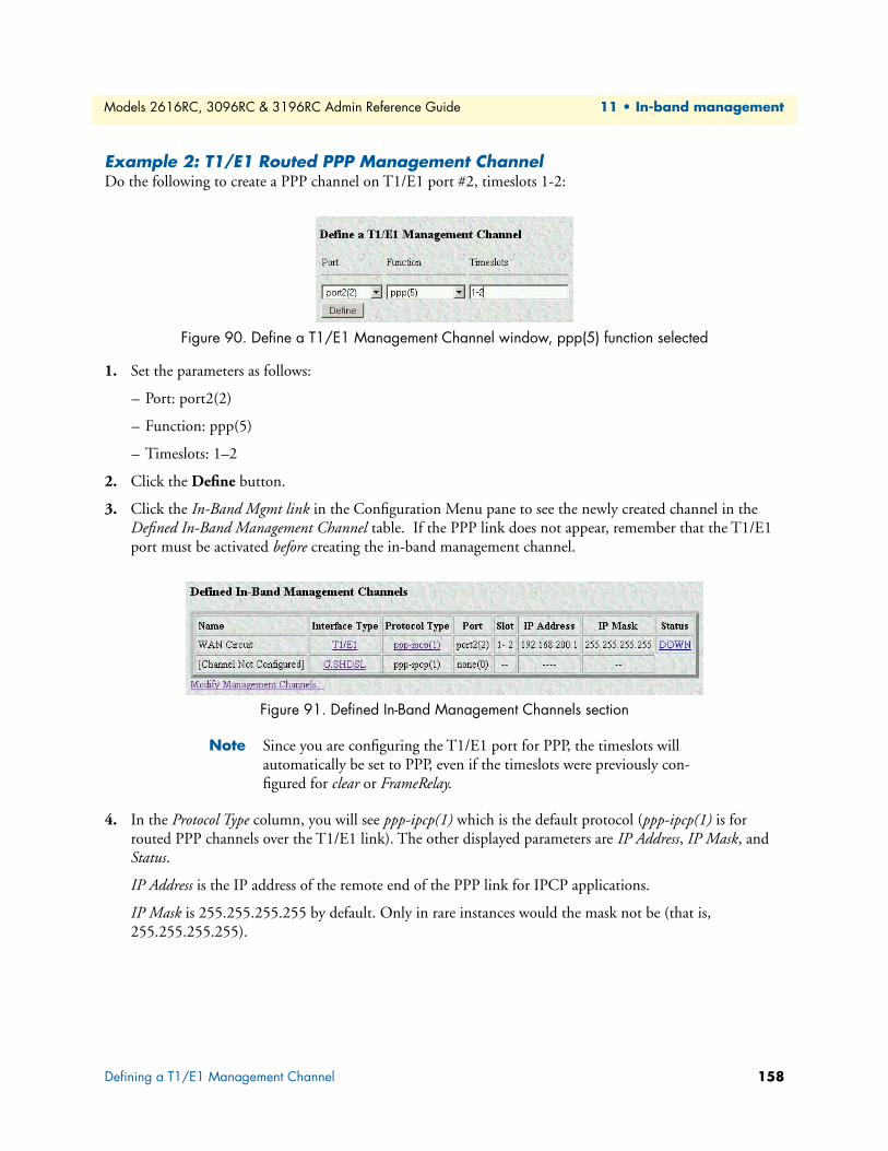
Models 2616RC, 3096RC & 3196RC Admin Reference Guide 11 • In-band management
Example 2: T1/E1 Routed PPP Management ChannelDo the following to create a PPP channel on T1/E1 port #2, timeslots 1-2:
Figure 90. Define a T1/E1 Management Channel window, ppp(5) function selected
1. Set the parameters as follows:
– Port: port2(2)
– Function: ppp(5)
– Timeslots: 1–2
2. Click the Define button.
3. Click the In-Band Mgmt link in the Configuration Menu pane to see the newly created channel in the Defined In-Band Management Channel table. If the PPP link does not appear, remember that the T1/E1 port must be activated before creating the in-band management channel.
Figure 91. Defined In-Band Management Channels section
Note Since you are configuring the T1/E1 port for PPP, the timeslots will automatically be set to PPP, even if the timeslots were previously con-figured for clear or FrameRelay.
4. In the Protocol Type column, you will see ppp-ipcp(1) which is the default protocol (ppp-ipcp(1) is for routed PPP channels over the T1/E1 link). The other displayed parameters are IP Address, IP Mask, and Status.
IP Address is the IP address of the remote end of the PPP link for IPCP applications.
IP Mask is 255.255.255.255 by default. Only in rare instances would the mask not be (that is, 255.255.255.255).
Defining a T1/E1 Management Channel 158
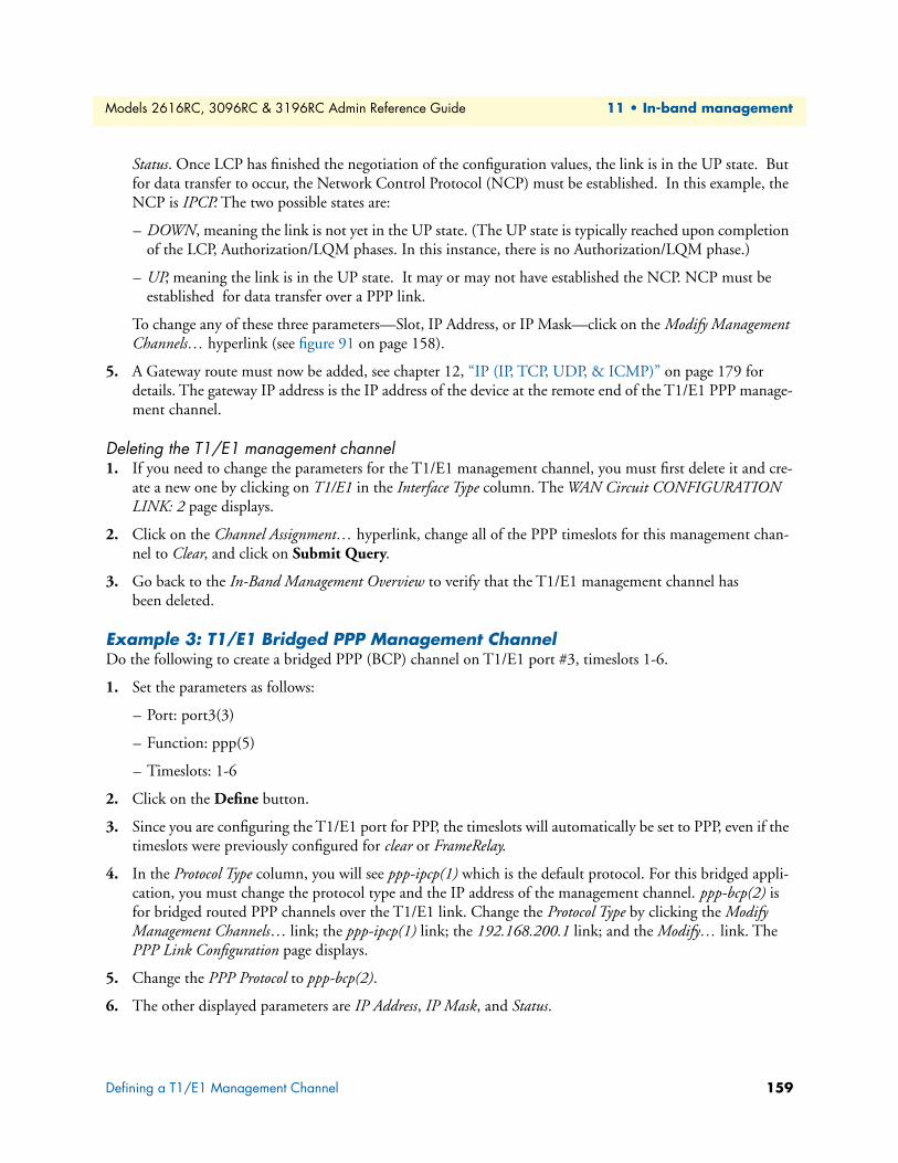
Models 2616RC, 3096RC & 3196RC Admin Reference Guide 11 • In-band management
Status. Once LCP has finished the negotiation of the configuration values, the link is in the UP state. But for data transfer to occur, the Network Control Protocol (NCP) must be established. In this example, the NCP is IPCP. The two possible states are:
– DOWN, meaning the link is not yet in the UP state. (The UP state is typically reached upon completion of the LCP, Authorization/LQM phases. In this instance, there is no Authorization/LQM phase.)
– UP, meaning the link is in the UP state. It may or may not have established the NCP. NCP must be established for data transfer over a PPP link.
To change any of these three parameters—Slot, IP Address, or IP Mask—click on the Modify Management Channels… hyperlink (see figure 91 on page 158).
5. A Gateway route must now be added, see chapter 12, “IP (IP, TCP, UDP, & ICMP)” on page 179 for details. The gateway IP address is the IP address of the device at the remote end of the T1/E1 PPP manage-ment channel.
Deleting the T1/E1 management channel1. If you need to change the parameters for the T1/E1 management channel, you must first delete it and cre-
ate a new one by clicking on T1/E1 in the Interface Type column. The WAN Circuit CONFIGURATION LINK: 2 page displays.
2. Click on the Channel Assignment… hyperlink, change all of the PPP timeslots for this management chan-nel to Clear, and click on Submit Query.
3. Go back to the In-Band Management Overview to verify that the T1/E1 management channel has been deleted.
Example 3: T1/E1 Bridged PPP Management ChannelDo the following to create a bridged PPP (BCP) channel on T1/E1 port #3, timeslots 1-6.
1. Set the parameters as follows:
– Port: port3(3)
– Function: ppp(5)
– Timeslots: 1-6
2. Click on the Define button.
3. Since you are configuring the T1/E1 port for PPP, the timeslots will automatically be set to PPP, even if the timeslots were previously configured for clear or FrameRelay.
4. In the Protocol Type column, you will see ppp-ipcp(1) which is the default protocol. For this bridged appli-cation, you must change the protocol type and the IP address of the management channel. ppp-bcp(2) is for bridged routed PPP channels over the T1/E1 link. Change the Protocol Type by clicking the Modify Management Channels… link; the ppp-ipcp(1) link; the 192.168.200.1 link; and the Modify… link. The PPP Link Configuration page displays.
5. Change the PPP Protocol to ppp-bcp(2).
6. The other displayed parameters are IP Address, IP Mask, and Status.
Defining a T1/E1 Management Channel 159
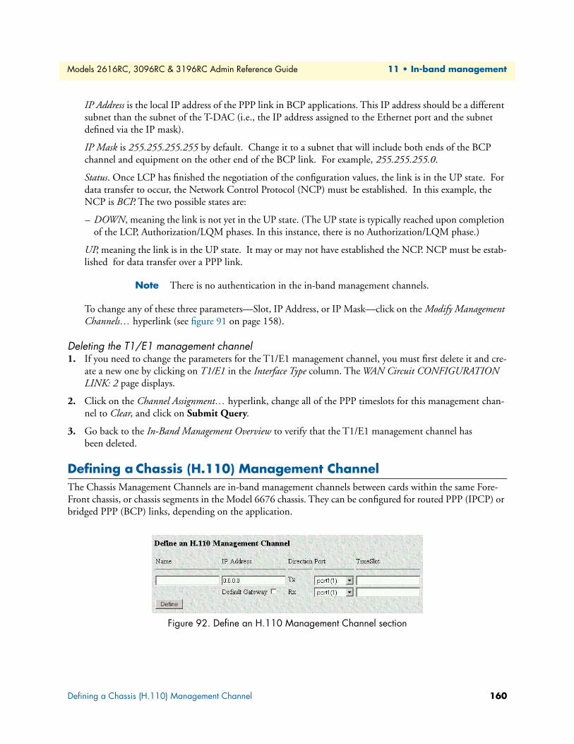
Models 2616RC, 3096RC & 3196RC Admin Reference Guide 11 • In-band management
IP Address is the local IP address of the PPP link in BCP applications. This IP address should be a different subnet than the subnet of the T-DAC (i.e., the IP address assigned to the Ethernet port and the subnet defined via the IP mask).
IP Mask is 255.255.255.255 by default. Change it to a subnet that will include both ends of the BCP channel and equipment on the other end of the BCP link. For example, 255.255.255.0.
Status. Once LCP has finished the negotiation of the configuration values, the link is in the UP state. For data transfer to occur, the Network Control Protocol (NCP) must be established. In this example, the NCP is BCP. The two possible states are:
– DOWN, meaning the link is not yet in the UP state. (The UP state is typically reached upon completion of the LCP, Authorization/LQM phases. In this instance, there is no Authorization/LQM phase.)
UP, meaning the link is in the UP state. It may or may not have established the NCP. NCP must be estab-lished for data transfer over a PPP link.
Note There is no authentication in the in-band management channels.
To change any of these three parameters—Slot, IP Address, or IP Mask—click on the Modify Management Channels… hyperlink (see figure 91 on page 158).
Deleting the T1/E1 management channel1. If you need to change the parameters for the T1/E1 management channel, you must first delete it and cre-
ate a new one by clicking on T1/E1 in the Interface Type column. The WAN Circuit CONFIGURATION LINK: 2 page displays.
2. Click on the Channel Assignment… hyperlink, change all of the PPP timeslots for this management chan-nel to Clear, and click on Submit Query.
3. Go back to the In-Band Management Overview to verify that the T1/E1 management channel has been deleted.
Defining a Chassis (H.110) Management ChannelThe Chassis Management Channels are in-band management channels between cards within the same Fore-Front chassis, or chassis segments in the Model 6676 chassis. They can be configured for routed PPP (IPCP) or bridged PPP (BCP) links, depending on the application.
Figure 92. Define an H.110 Management Channel section
Defining a Chassis (H.110) Management Channel 160
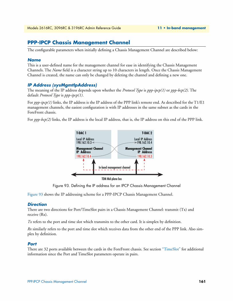
Models 2616RC, 3096RC & 3196RC Admin Reference Guide 11 • In-band management
PPP-IPCP Chassis Management ChannelThe configurable parameters when initially defining a Chassis Management Channel are described below:
NameThis is a user-defined name for the management channel for ease in identifying the Chassis Management Channels. The Name field is a character string up to 10 characters in length. Once the Chassis Management Channel is created, the name can only be changed by deleting the channel and defining a new one.
IP Address (sysMgmtIpAddress)The meaning of the IP address depends upon whether the Protocol Type is ppp-ipcp(1) or ppp-bcp(2). The default Protocol Type is ppp-ipcp(1).
For ppp-ipcp(1) links, the IP address is the IP address of the PPP link’s remote end. As described for the T1/E1 management channels, the easiest configuration is with IP addresses in the same subnet as the cards in the ForeFront chassis.
For ppp-bcp(2) links, the IP address is the local IP address, that is, the IP address on this end of the PPP link.
Figure 93. Defining the IP address for an IPCP Chassis Management Channel
Figure 93 shows the IP addressing scheme for a PPP-IPCP Chassis Management Channel.
DirectionThere are two directions for Port/TimeSlot pairs in a Chassis Management Channel: transmit (Tx) and receive (Rx).
Tx refers to the port and time slot which transmits to the other card. It is simplex by definition.
Rx similarly refers to the port and time slot which receives data from the other end of the PPP link. Also sim-plex by definition.
PortThere are 32 ports available between the cards in the ForeFront chassis. See section “TimeSlot” for additional information since the Port and TimeSlot parameters operate in pairs.
T-DAC 1
Local IP Address198.162.10.3
Local IP Address198.162.10.4
Management ChannelIP Address
TDM Mid-plane bus
In-band management channel
Management ChannelIP Address
T-DAC 2
198.162.10.4 198.162.10.3
PPP-IPCP Chassis Management Channel 161

Models 2616RC, 3096RC & 3196RC Admin Reference Guide 11 • In-band management
• Tx Port (sysMgmtPortTx)—The port number on which the local T-DAC transmits the in-band manage-ment data. The port selected must be the same as that selected for the receive port at the remote T-DAC. Parameter values range from port1(1) to port32(32).
• Rx Port (sysMgmtPortRx)—The port number on which the local T-DAC receives the in-band manage-ment data. The port selected must be the same as that selected for the transmit port at the remote T-DAC. Parameter values range from port1(1) to port32(32).
TimeSlotEach port contains 128 DS0 time slots. A DS0 time slot is 64 kbps simplex for the Chassis Management Channels. Prior to configuring the Port and TimeSlot parameters for an in-band management link, go to the DS0 Mapping management page in the T-DAC. Do not use any of the port and time slot combinations which are already configured for H.110 in the Defined Mappings table. You must select unique port and slot combina-tions. Consider Port and TimeSlot as an ordered pair, (Port, TimeSlot). Each ordered pair, (Port, TimeSlot), can be used only once in each card. Secondly, the Tx (Port, TimeSlot) on this end of the link is the Rx (Port, TimeSlot) of the remote end of the link.
• Tx Timeslot (sysMgmtSlotTx)—Defines the timeslot that the local T-DAC transmits in-band management data. The specified timeslot value must be the same as that used for the receive timeslot parameter at the remote T-DAC. Valid parameter values are positive integers ranging from 1–128.
• Rx Timeslot (sysMgmtSlotRx)—Defines the timeslot that the local T-DAC receives in-band management data. The specified timeslot value must be the same as that used for the transmit timeslot parameter at the remote T-DAC. Valid parameter values are positive integers ranging from 1–128.
Default Gateway (sysMgmtDefaultGateway)By checking the Default Gateway box, the default gateway is automatically added to the routing table upon defining the Chassis Management Channel. This box typically is not checked on the card which has the incom-ing T1/E1 management channel. You would normally check this box for the other cards in the ForeFront chassis.
PPP-IPCP Chassis Management Channel 162
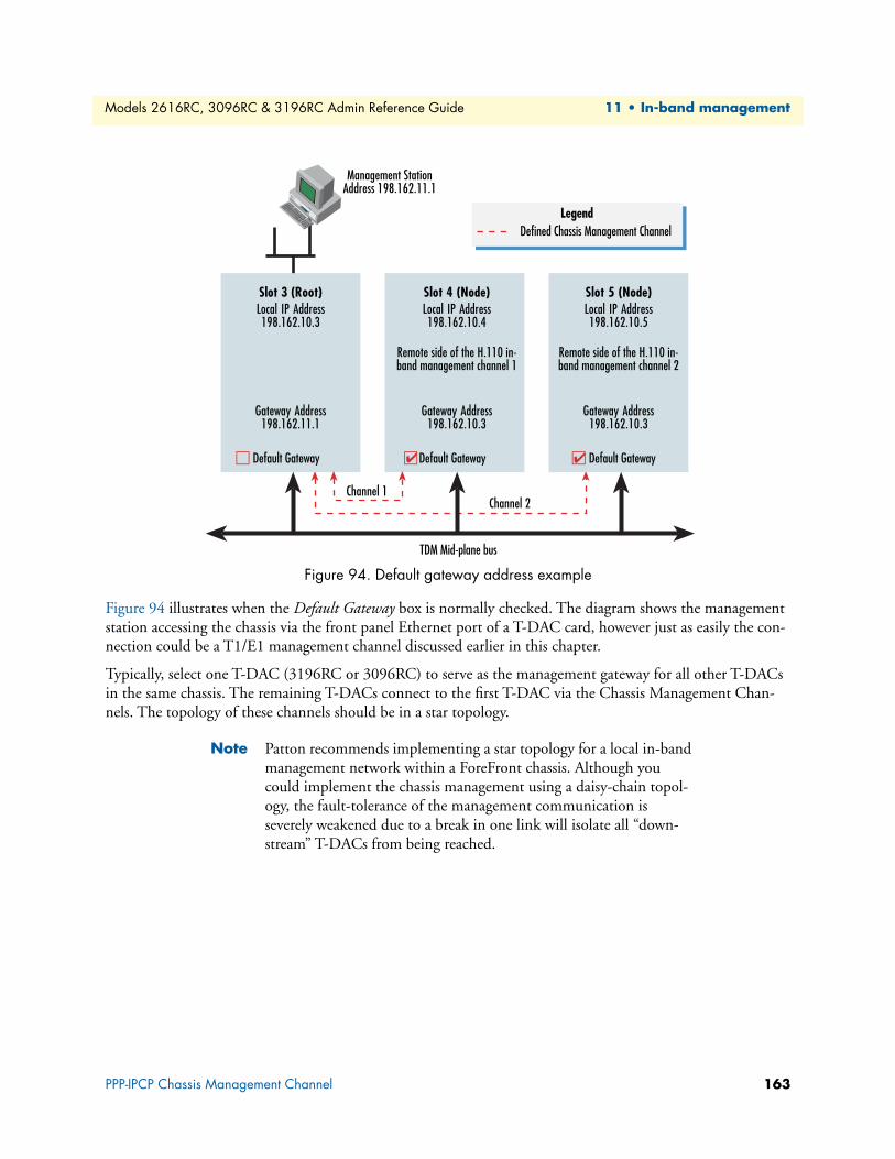
Models 2616RC, 3096RC & 3196RC Admin Reference Guide 11 • In-band management
Figure 94. Default gateway address example
Figure 94 illustrates when the Default Gateway box is normally checked. The diagram shows the management station accessing the chassis via the front panel Ethernet port of a T-DAC card, however just as easily the con-nection could be a T1/E1 management channel discussed earlier in this chapter.
Typically, select one T-DAC (3196RC or 3096RC) to serve as the management gateway for all other T-DACs in the same chassis. The remaining T-DACs connect to the first T-DAC via the Chassis Management Chan-nels. The topology of these channels should be in a star topology.
Note Patton recommends implementing a star topology for a local in-band management network within a ForeFront chassis. Although you could implement the chassis management using a daisy-chain topol-ogy, the fault-tolerance of the management communication is severely weakened due to a break in one link will isolate all “down-stream” T-DACs from being reached.
Slot 4 (Node)Local IP Address198.162.10.3
Gateway Address198.162.11.1
Local IP Address198.162.10.4
Gateway Address198.162.10.3
LegendDefined Chassis Management Channel
TDM Mid-plane bus
Slot 5 (Node)Local IP Address198.162.10.5
Gateway Address198.162.10.3
Slot 3 (Root)
Default GatewayDefault Gateway ✔ Default Gateway ✔
Remote side of the H.110 in-band management channel 1
Remote side of the H.110 in-band management channel 2
Channel 2Channel 1
Management StationAddress 198.162.11.1
PPP-IPCP Chassis Management Channel 163
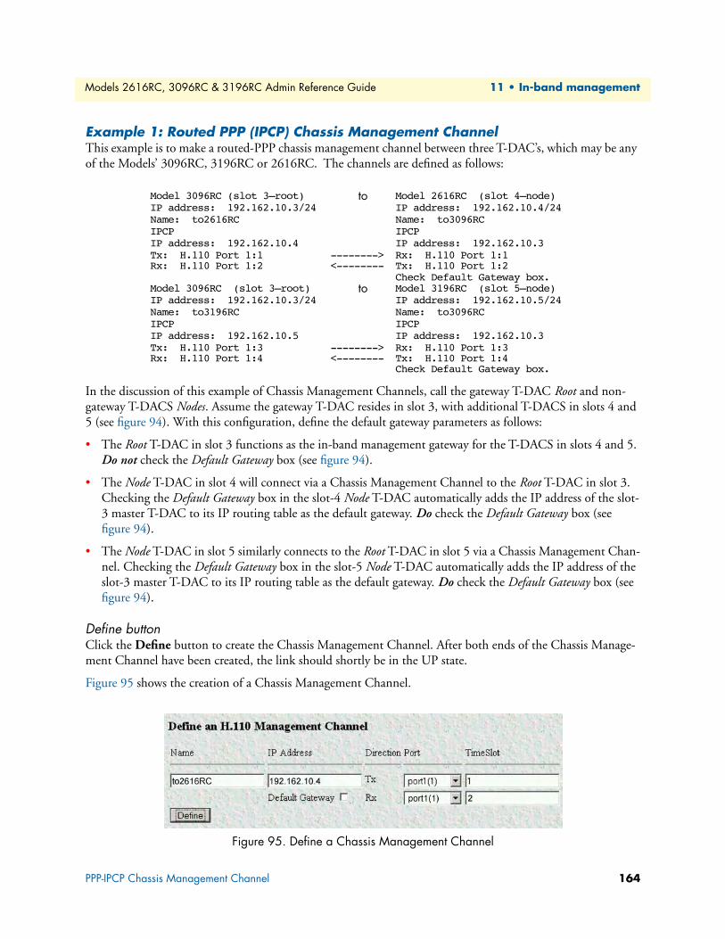
Models 2616RC, 3096RC & 3196RC Admin Reference Guide 11 • In-band management
Example 1: Routed PPP (IPCP) Chassis Management ChannelThis example is to make a routed-PPP chassis management channel between three T-DAC’s, which may be any of the Models’ 3096RC, 3196RC or 2616RC. The channels are defined as follows:
In the discussion of this example of Chassis Management Channels, call the gateway T-DAC Root and non-gateway T-DACS Nodes. Assume the gateway T-DAC resides in slot 3, with additional T-DACS in slots 4 and 5 (see figure 94). With this configuration, define the default gateway parameters as follows:
• The Root T-DAC in slot 3 functions as the in-band management gateway for the T-DACS in slots 4 and 5. Do not check the Default Gateway box (see figure 94).
• The Node T-DAC in slot 4 will connect via a Chassis Management Channel to the Root T-DAC in slot 3. Checking the Default Gateway box in the slot-4 Node T-DAC automatically adds the IP address of the slot-3 master T-DAC to its IP routing table as the default gateway. Do check the Default Gateway box (see figure 94).
• The Node T-DAC in slot 5 similarly connects to the Root T-DAC in slot 5 via a Chassis Management Chan-nel. Checking the Default Gateway box in the slot-5 Node T-DAC automatically adds the IP address of the slot-3 master T-DAC to its IP routing table as the default gateway. Do check the Default Gateway box (see figure 94).
Define buttonClick the Define button to create the Chassis Management Channel. After both ends of the Chassis Manage-ment Channel have been created, the link should shortly be in the UP state.
Figure 95 shows the creation of a Chassis Management Channel.
Figure 95. Define a Chassis Management Channel
Model 3096RC (slot 3—root) to Model 2616RC (slot 4—node)IP address: 192.162.10.3/24 IP address: 192.162.10.4/24Name: to2616RC Name: to3096RCIPCP IPCPIP address: 192.162.10.4 IP address: 192.162.10.3Tx: H.110 Port 1:1 --------> Rx: H.110 Port 1:1Rx: H.110 Port 1:2 <-------- Tx: H.110 Port 1:2
Check Default Gateway box.Model 3096RC (slot 3—root) to Model 3196RC (slot 5—node)IP address: 192.162.10.3/24 IP address: 192.162.10.5/24Name: to3196RC Name: to3096RCIPCP IPCPIP address: 192.162.10.5 IP address: 192.162.10.3Tx: H.110 Port 1:3 --------> Rx: H.110 Port 1:3Rx: H.110 Port 1:4 <-------- Tx: H.110 Port 1:4
Check Default Gateway box.
PPP-IPCP Chassis Management Channel 164
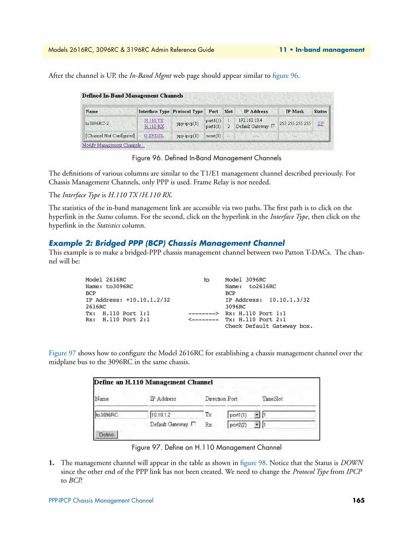
Models 2616RC, 3096RC & 3196RC Admin Reference Guide 11 • In-band management
After the channel is UP, the In-Band Mgmt web page should appear similar to figure 96.
Figure 96. Defined In-Band Management Channels
The definitions of various columns are similar to the T1/E1 management channel described previously. For Chassis Management Channels, only PPP is used. Frame Relay is not needed.
The Interface Type is H.110 TX /H.110 RX.
The statistics of the in-band management link are accessible via two paths. The first path is to click on the hyperlink in the Status column. For the second, click on the hyperlink in the Interface Type, then click on the hyperlink in the Statistics column.
Example 2: Bridged PPP (BCP) Chassis Management ChannelThis example is to make a bridged-PPP chassis management channel between two Patton T-DACs. The chan-nel will be:
Figure 97 shows how to configure the Model 2616RC for establishing a chassis management channel over the midplane bus to the 3096RC in the same chassis.
Figure 97. Define an H.110 Management Channel
1. The management channel will appear in the table as shown in figure 98. Notice that the Status is DOWN since the other end of the PPP link has not been created. We need to change the Protocol Type from IPCP to BCP.
Model 2616RC to Model 3096RCName: to3096RC Name: to2616RCBCP BCPIP Address: +10.10.1.2/32 IP Address: 10.10.1.3/322616RC 3096RCTx: H.110 Port 1:1 --------> Rx: H.110 Port 1:1Rx: H.110 Port 2:1 <-------- Tx: H.110 Port 2:1
Check Default Gateway box.
PPP-IPCP Chassis Management Channel 165
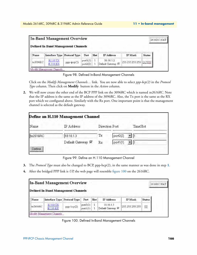
Models 2616RC, 3096RC & 3196RC Admin Reference Guide 11 • In-band management
Figure 98. Defined In-Band Management Channels
Click on the Modify Management Channels… link. You are now able to select ppp-bcp(2) in the Protocol Type column. Then click on Modify button in the Action column.
2. We will now create the other end of the BCP PPP link on the 3096RC which is named to2616RC. Note that the IP address is the same as the IP address of the 3096RC. Also, the Tx port is the same as the RX port which we configured above. Similarly with the Rx port. One important point is that the management channel is selected as the default gateway.
Figure 99. Define an H.110 Management Channel
3. The Protocol Type must also be changed to BCP, ppp-bcp(2), in the same manner as was done in step 1.
4. After the bridged PPP link is UP, the web page will resemble figure 100 on the 2616RC.
Figure 100. Defined In-Band Management Channels
PPP-IPCP Chassis Management Channel 166
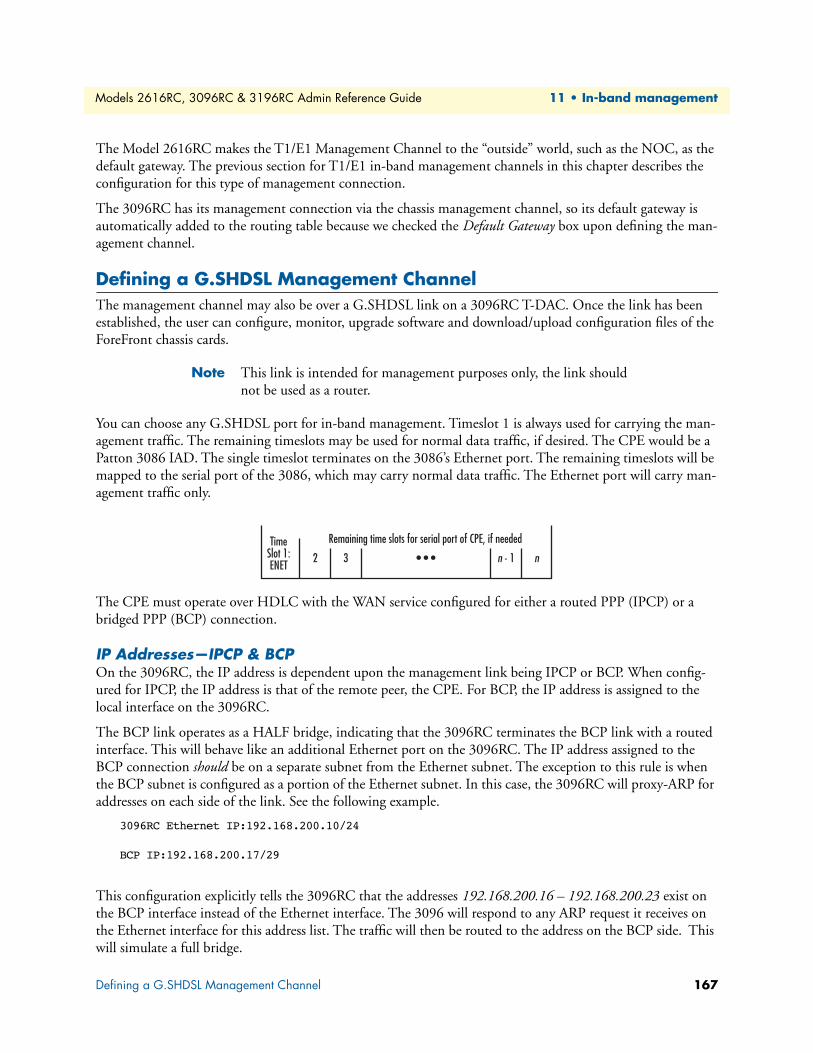
Models 2616RC, 3096RC & 3196RC Admin Reference Guide 11 • In-band management
The Model 2616RC makes the T1/E1 Management Channel to the “outside” world, such as the NOC, as the default gateway. The previous section for T1/E1 in-band management channels in this chapter describes the configuration for this type of management connection.
The 3096RC has its management connection via the chassis management channel, so its default gateway is automatically added to the routing table because we checked the Default Gateway box upon defining the man-agement channel.
Defining a G.SHDSL Management ChannelThe management channel may also be over a G.SHDSL link on a 3096RC T-DAC. Once the link has been established, the user can configure, monitor, upgrade software and download/upload configuration files of the ForeFront chassis cards.
Note This link is intended for management purposes only, the link should not be used as a router.
You can choose any G.SHDSL port for in-band management. Timeslot 1 is always used for carrying the man-agement traffic. The remaining timeslots may be used for normal data traffic, if desired. The CPE would be a Patton 3086 IAD. The single timeslot terminates on the 3086’s Ethernet port. The remaining timeslots will be mapped to the serial port of the 3086, which may carry normal data traffic. The Ethernet port will carry man-agement traffic only.
The CPE must operate over HDLC with the WAN service configured for either a routed PPP (IPCP) or a bridged PPP (BCP) connection.
IP Addresses—IPCP & BCPOn the 3096RC, the IP address is dependent upon the management link being IPCP or BCP. When config-ured for IPCP, the IP address is that of the remote peer, the CPE. For BCP, the IP address is assigned to the local interface on the 3096RC.
The BCP link operates as a HALF bridge, indicating that the 3096RC terminates the BCP link with a routed interface. This will behave like an additional Ethernet port on the 3096RC. The IP address assigned to the BCP connection should be on a separate subnet from the Ethernet subnet. The exception to this rule is when the BCP subnet is configured as a portion of the Ethernet subnet. In this case, the 3096RC will proxy-ARP for addresses on each side of the link. See the following example.
3096RC Ethernet IP:192.168.200.10/24
BCP IP:192.168.200.17/29
This configuration explicitly tells the 3096RC that the addresses 192.168.200.16 – 192.168.200.23 exist on the BCP interface instead of the Ethernet interface. The 3096 will respond to any ARP request it receives on the Ethernet interface for this address list. The traffic will then be routed to the address on the BCP side. This will simulate a full bridge.
TimeSlot 1:ENET
2 3
Remaining time slots for serial port of CPE, if needed
• • • n - 1 n
Defining a G.SHDSL Management Channel 167
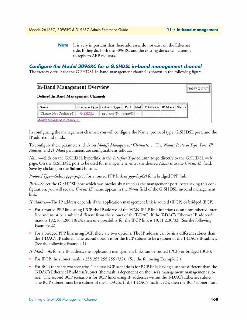
Models 2616RC, 3096RC & 3196RC Admin Reference Guide 11 • In-band management
Note It is very important that these addresses do not exist on the Ethernet side. If they do, both the 3096RC and the existing device will attempt to reply to ARP requests.
Configure the Model 3096RC for a G.SHDSL in-band management channelThe factory default for the G.SHDSL in-band management channel is shown in the following figure.
In configuring the management channel, you will configure the Name, protocol type, G.SHDSL port, and the IP address and mask.
To configure these parameters, click on Modify Management Channels…. The Name, Protocol Type, Port, IP Address, and IP Mask parameters are configurable as follows:
Name—click on the G.SHDSL hyperlink in the Interface Type column to go directly to the G.SHDSL web page. On the G.SHDSL port to be used for management, enter the desired Name into the Circuit ID field. Save by clicking on the Submit button.
Protocol Type—Select ppp-ipcp(1) for a routed PPP link or ppp-bcp(2) for a bridged PPP link.
Port—Select the G.SHDSL port which was previously named as the management port. After saving this con-figuration, you will see the Circuit ID name appear in the Name field of the G.SHDSL in-band management link.
IP Address—The IP address depends if the application management link is routed (IPCP) or bridged (BCP).
• For a routed PPP link using IPCP, the IP address of the WAN IPCP link functions as an unnumbered inter-face and must be a subnet different from the subnet of the T-DAC. If the T-DAC’s Ethernet IP address/mask is 192.168.200.10/24, then one possibility for the IPCP link is 10.11.2.30/32. (See the following Example 2.)
• For a bridged PPP link using BCP, there are two options. The IP address can be in a different subnet than the T-DAC’s IP subnet. The second option is for the BCP subnet to be a subnet of the T-DAC’s IP subnet. (See the following Example 1).
IP Mask—As for the IP address, the application management links can be routed IPCP) or bridged (BCP).
• For IPCP, the subnet mask is 255.255.255.255 (/32). (See the following Example 2.)
• For BCP, there are two scenarios. The first BCP scenario is for BCP links having a subnet different than the T-DAC’s Ethernet IP address/subnet (the mask is dependent on the user’s management management sub-net). The second BCP scenario is for BCP links using IP addresses within the T-DAC’s Ethernet subnet. The BCP subnet must be a subnet of the T-DAC’s. If the T-DAC’s mask is /24, then the BCP subnet must
Defining a G.SHDSL Management Channel 168
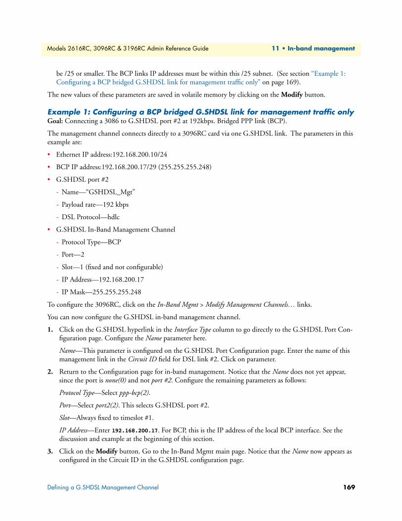
Models 2616RC, 3096RC & 3196RC Admin Reference Guide 11 • In-band management
be /25 or smaller. The BCP links IP addresses must be within this /25 subnet. (See section “Example 1: Configuring a BCP bridged G.SHDSL link for management traffic only” on page 169).
The new values of these parameters are saved in volatile memory by clicking on the Modify button.
Example 1: Configuring a BCP bridged G.SHDSL link for management traffic onlyGoal: Connecting a 3086 to G.SHDSL port #2 at 192kbps. Bridged PPP link (BCP).
The management channel connects directly to a 3096RC card via one G.SHDSL link. The parameters in this example are:
• Ethernet IP address:192.168.200.10/24
• BCP IP address:192.168.200.17/29 (255.255.255.248)
• G.SHDSL port #2
- Name—“GSHDSL_Mgt”
- Payload rate—192 kbps
- DSL Protocol—hdlc
• G.SHDSL In-Band Management Channel
- Protocol Type—BCP
- Port—2
- Slot—1 (fixed and not configurable)
- IP Address—192.168.200.17
- IP Mask—255.255.255.248
To configure the 3096RC, click on the In-Band Mgmt > Modify Management Channels… links.
You can now configure the G.SHDSL in-band management channel.
1. Click on the G.SHDSL hyperlink in the Interface Type column to go directly to the G.SHDSL Port Con-figuration page. Configure the Name parameter here.
Name—This parameter is configured on the G.SHDSL Port Configuration page. Enter the name of this management link in the Circuit ID field for DSL link #2. Click on parameter.
2. Return to the Configuration page for in-band management. Notice that the Name does not yet appear, since the port is none(0) and not port #2. Configure the remaining parameters as follows:
Protocol Type—Select ppp-bcp(2).
Port—Select port2(2). This selects G.SHDSL port #2.
Slot—Always fixed to timeslot #1.
IP Address—Enter 192.168.200.17. For BCP, this is the IP address of the local BCP interface. See the discussion and example at the beginning of this section.
3. Click on the Modify button. Go to the In-Band Mgmt main page. Notice that the Name now appears as configured in the Circuit ID in the G.SHDSL configuration page.
Defining a G.SHDSL Management Channel 169
Models 2616RC, 3096RC & 3196RC Admin Reference Guide 11 • In-band management
If you are connecting the serial port on the remote CPE to a device, then you will need to map timeslots 2–3 to its destination in the 3096RC. (If the remote CPE’s serial port is not to be used, do not map timeslots 2–3 of G.SHDSL port #2 to anything.)
The remaining step is to configure the 3086 CPE.
Configure Model 3086 for an in-band management channelThis section will describe the configuration of the Model 3086, the configuration of the G.SHDSL manage-ment channel, and a summary of the various parameters.
For complete configuration of the Model 3086, refer to the Model 3086 Getting Started Guide available on the Patton website. Some of the configurable parameters must meet certain requirements for this application.
G.SHDSL parameters:
• Intended DSL Data Rate—set to 192kbps
• DSL Protocol—must be “hdlc”
• DSL Allocation—must be “Ethernet and Serial”
• Intended Serial Rate—Set to 128kbps. This is equal to the “Intended DSL Data Rate” minus 64kbps. The 64kbps represents the single DS0 timeslot which terminates on the Ethernet for all the management traffic. The remaining timeslots make up the “Intended Serial Rate” is mapped to the serial port for regular data.
Service Parameters:
• Configure for bridged PPP
• IP address: 192.168.200.18/24
Defining a G.SHDSL Management Channel 170
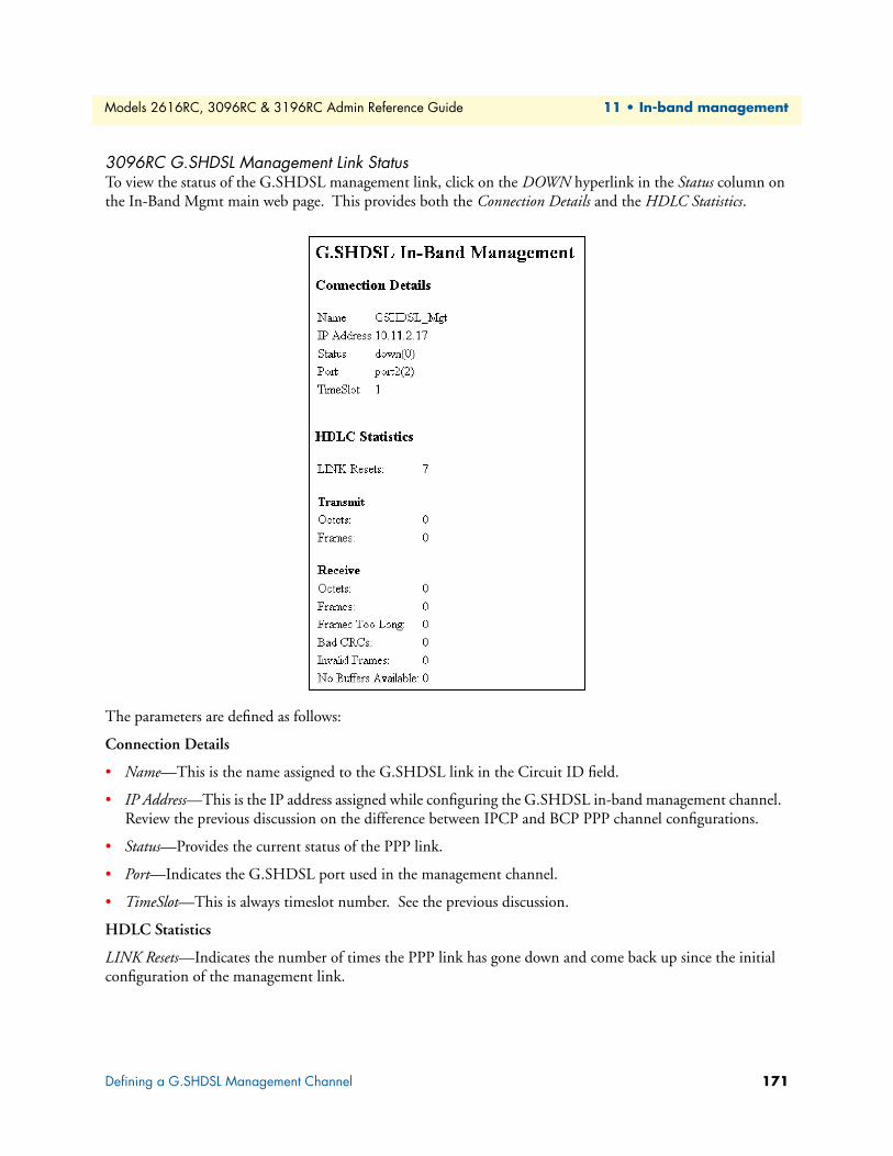
Models 2616RC, 3096RC & 3196RC Admin Reference Guide 11 • In-band management
3096RC G.SHDSL Management Link StatusTo view the status of the G.SHDSL management link, click on the DOWN hyperlink in the Status column on the In-Band Mgmt main web page. This provides both the Connection Details and the HDLC Statistics.
The parameters are defined as follows:
Connection Details
• Name—This is the name assigned to the G.SHDSL link in the Circuit ID field.
• IP Address—This is the IP address assigned while configuring the G.SHDSL in-band management channel. Review the previous discussion on the difference between IPCP and BCP PPP channel configurations.
• Status—Provides the current status of the PPP link.
• Port—Indicates the G.SHDSL port used in the management channel.
• TimeSlot—This is always timeslot number. See the previous discussion.
HDLC Statistics
LINK Resets—Indicates the number of times the PPP link has gone down and come back up since the initial configuration of the management link.
Defining a G.SHDSL Management Channel 171
Models 2616RC, 3096RC & 3196RC Admin Reference Guide 11 • In-band management
Transmit
• Octets—The number of octets transmitted as data to the remote CPE. This includes frames transmitted in the negotiation phases.
• Frames—The number of PPP (HDLC) frames transmitted to the remote CPE. This includes frames trans-mitted in the negotiation phases.
Receive
Octets—The number of octets received as data from the remote CPE. This includes frames transmitted in the negotiation phases.
Frames—The number of PPP (HDLC) frames received from the remote CPE. This includes frames transmit-ted in the negotiation phases.
Frames Too Long—The number of received PPP (HDLC) frames exceeding the MRU which is configured in the PPP Link Configuration page (in the PPP subsystem).
Bad CRCs—The number of received PPP (HDLC) frames with bad CRCs.
Invalid Frames—The number of received frames with invalid frames.
No Buffers Available—The number of frames received when no receive buffers were available.
Example 2: Configuring an IPCP routed G.SHDSL link for management traffic onlyGoal: Connecting a 3086 to G.SHDSL port #3 at 192kbps. Routed PPP link (IPCP).
The management channel connects directly to a 3096RC card via one G.SHDSL link. The parameters in this example are:
• Ethernet IP address:192.168.200.10/24
• IP address of remote peer:10.11.2.30/32
• G.SHDSL port #3
- Name—“GSHDSL_Mgt”
- Payload rate—192 kbps
- DSL Protocol—hdlc
• G.SHDSL In-Band Management Channel
- Protocol Type—IPCP
- Port—3
- Slot—1 (fixed and not configurable)
- IP Address—10.11.2.30
- IP Mask—255.255.255.255
To configure the 3096RC, click on the In-Band Mgmt > Modify Management Channels… links.
You can now configure the G.SHDSL in-band management channel.
Defining a G.SHDSL Management Channel 172
Models 2616RC, 3096RC & 3196RC Admin Reference Guide 11 • In-band management
1. Click on the G.SHDSL hyperlink in the Interface Type column to go directly to the G.SHDSL Port Con-figuration page. Configure the Name parameter here.
Name—This parameter is configured on the G.SHDSL Port Configuration page. Enter the name of this management link in the Circuit ID field for DSL link #3. Click on parameter.
2. Return to the Configuration page for in-band management. Notice that the Name does not yet appear, since the port is none(0) and not port #2. Configure the remaining parameters as follows:
Protocol Type—Select ppp-ipcp(1).
Port—Select port3(3). This selects G.SHDSL port #3.
Slot—Always fixed to timeslot #1.
IP Address—Enter 10.11.2.30. For IPCP, this is the IP address assigned to the remote peer. The IP mask is 255.255.255.255.
3. Click on the Modify button. Go to the In-Band Mgmt main page. Notice that the Name now appears as configured in the Circuit ID in the G.SHDSL configuration page.
Since we are not connecting anything to the serial port of the 3086, we do not map timeslots of G.SHDSL port #3 to anything.
The remaining step is to configure the 3086 CPE.
Configure Model 3086 for an in-band management channelThis section will describe the configuration of the Model 3086, the configuration of the G.SHDSL manage-ment channel, and a summary of the various parameters.
For complete configuration of the Model 3086, refer to the Model 3086 Getting Started Guide available on the Patton website. Some of the configurable parameters must meet certain requirements for this application.
G.SHDSL parameters:
• Intended DSL Data Rate—set to 192kbps
• DSL Protocol—must be “hdlc”
• DSL Allocation—must be “Ethernet and Serial”
• Intended Serial Rate—Set to 128kbps. This is equal to the “Intended DSL Data Rate” minus 64kbps. The 64kbps represents the single DS0 timeslot which terminates on the Ethernet for all the management traffic. The remaining timeslots make up the “Intended Serial Rate” is mapped to the serial port for regular data.
Service Parameters:
• Configure for routed PPP
• IP address—The WAN port will accept the IP address from the 3096RC IPCP link, since it operates as an unnumbered interface.
Ethernet IP address:
10.10.1.100/24 (this IP address is in a different subnet than either the 3096RC or IPCP IP addresses.)
Defining a G.SHDSL Management Channel 173
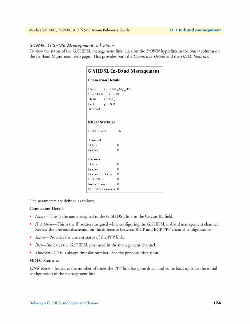
Models 2616RC, 3096RC & 3196RC Admin Reference Guide 11 • In-band management
3096RC G.SHDSL Management Link StatusTo view the status of the G.SHDSL management link, click on the DOWN hyperlink in the Status column on the In-Band Mgmt main web page. This provides both the Connection Details and the HDLC Statistics.
The parameters are defined as follows:
Connection Details
• Name—This is the name assigned to the G.SHDSL link in the Circuit ID field.
• IP Address—This is the IP address assigned while configuring the G.SHDSL in-band management channel. Review the previous discussion on the difference between IPCP and BCP PPP channel configurations.
• Status—Provides the current status of the PPP link.
• Port—Indicates the G.SHDSL port used in the management channel.
• TimeSlot—This is always timeslot number. See the previous discussion.
HDLC Statistics
LINK Resets—Indicates the number of times the PPP link has gone down and come back up since the initial configuration of the management link.
Defining a G.SHDSL Management Channel 174
Models 2616RC, 3096RC & 3196RC Admin Reference Guide 11 • In-band management
Transmit
• Octets—The number of octets transmitted as data to the remote CPE. This includes frames transmitted in the negotiation phases.
• Frames—The number of PPP (HDLC) frames transmitted to the remote CPE. This includes frames trans-mitted in the negotiation phases.
Receive
Octets—The number of octets received as data from the remote CPE. This includes frames transmitted in the negotiation phases.
Frames—The number of PPP (HDLC) frames received from the remote CPE. This includes frames transmit-ted in the negotiation phases.
Frames Too Long—The number of received PPP (HDLC) frames exceeding the MRU which is configured in the PPP Link Configuration page (in the PPP subsystem).
Bad CRCs—The number of received PPP (HDLC) frames with bad CRCs.
Invalid Frames—The number of received frames with invalid frames.
No Buffers Available—The number of frames received when no receive buffers were available.
Defining a G.SHDSL Management Channel 175
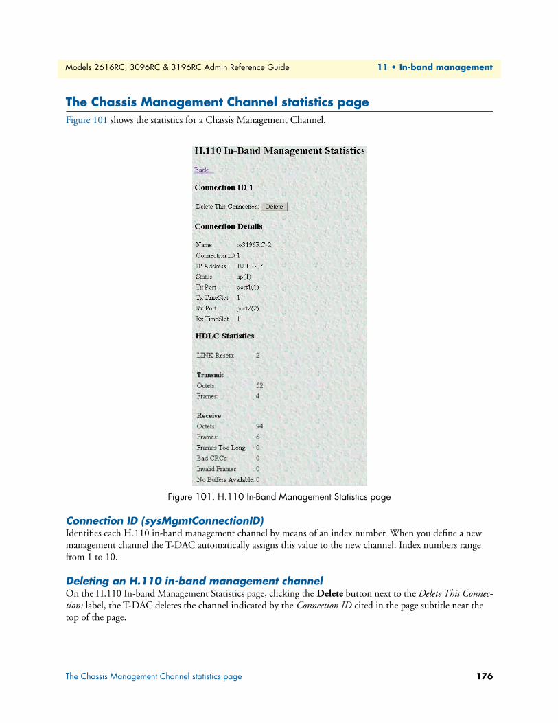
Models 2616RC, 3096RC & 3196RC Admin Reference Guide 11 • In-band management
The Chassis Management Channel statistics pageFigure 101 shows the statistics for a Chassis Management Channel.
Figure 101. H.110 In-Band Management Statistics page
Connection ID (sysMgmtConnectionID)Identifies each H.110 in-band management channel by means of an index number. When you define a new management channel the T-DAC automatically assigns this value to the new channel. Index numbers range from 1 to 10.
Deleting an H.110 in-band management channelOn the H.110 In-band Management Statistics page, clicking the Delete button next to the Delete This Connec-tion: label, the T-DAC deletes the channel indicated by the Connection ID cited in the page subtitle near the top of the page.
The Chassis Management Channel statistics page 176
Models 2616RC, 3096RC & 3196RC Admin Reference Guide 11 • In-band management
Connection DetailsIP Address (sysMgmtIpAddress)Specifies the IP address of the Ethernet interface for the ForeFront module on the remote side of the Chassis Management Channel). This IP address must identify another G.SHDSL or iDSL T-DAC in the same chassis (or chassis segment in the 6676).
Status (sysMgmtStatus)This is the current status of the connection. The status will either be down(0) or up(1). A status of down(0) indicates that the card is trying to establish an IP connection with the remote T-DAC over the Chassis Man-agement Channel. A status of up(1) means that the connection is up and is able to pass management data.
TX Port (sysMgmtPortTx)Defines the port number on which the local T-DAC will transmit in-band management data. The port selected must be the same as that selected for the receive port at the remote T-DAC. Parameter values range from port1(1) through port32(32).
Tx TimeSlot (sysMgmtSlotTx)Defines the timeslot that the local T-DAC will use to transmit in-band management data. The specified timeslot value must be the same as that used for the receive timeslot parameter at the remote T-DAC. Valid parameter values are positive integers ranging from 1–128.
Rx Port (sysMgmtPortRx)Defines the port number on which the local T-DAC will receive in-band management data. The port selected must be the same as that selected for the transmit port at the remote T-DAC. Parameter values range from port1(1) through port32(32).
Rx TimeSlot (sysMgmtSlotRx)Defines the timeslot that the local T-DAC will use to receive in-band management data. The specified timeslot value must be the same as that used for the transmit timeslot parameter at the remote T-DAC. Valid parameter values are positive integers ranging from 1–128.
HDLC StatisticsLINK Resets (sysMgmtResets)Indicates the number of HDLC link resets since the T-DAC module was last rebooted or power-cycled. A link reset occurs whenever the HDLC connection is re-established after going down. A high number of transmis-sion errors on the link may cause the link to go down.
Transmit Octets (sysMgmtTxOctets)Indicates the total number of octets transmitted on the link since the PPP link was last rebooted or power-cycled.
Transmit Frames (sysMgmtTxMessageEnds)Indicates total number of HDLC frames transmitted since the PPP link was last rebooted or power-cycled.
Receive Octets (sysMgmtRxOctets)Indicates the total number of octets received since the PPP link was last rebooted or power-cycled.
The Chassis Management Channel statistics page 177
Models 2616RC, 3096RC & 3196RC Admin Reference Guide 11 • In-band management
Receive Frames (sysMgmtRxMessageEnds)Indicates the total number of HDLC frames received since the PPP link was last rebooted or power-cycled.
Receive Frames Too Long (sysMgmtRxPacketTooLong)Indicates the total number of HDLC frames longer than 1500 octets received since PPP link was last rebooted or power-cycled. Bit transmission errors on the HDLC link may cause this condition.
Receive Bad CRCs (sysMgmtRxBadCrc)Indicates the total number of received HDLC frames that contained a checksum error since the PPP link was last rebooted or power-cycled. The T-DAC calculates a check sum for each packet that traverses the link.
Receive Invalid Frames (sysMgmtRxInvalidFrame)Indicates the total number of invalid HDLC frames received since the PPP link was last rebooted or power-cycled. An invalid frame is any frame that does not conform to the frame format as specified by the HDLC protocol. Invalid frames can result from bit transmission errors on the link.
Receive No Buffers Available (sysMgmtRxNoBufferAvailable)Indicates the number of times the HDLC link ran out of receive buffers since the PPP link was last rebooted or power-cycled.
IP Routing table modificationsEven though the T1/E1 management channel and the Chassis Management Channels may all be UP, this does not guarantee access to all the cards until the routing table is correct. Review and edit the IP routing table by clicking on the IP link in the T-DAC’s configuration menu pane, to display the IP main window, then click the Routing Info… link. For additional information on the IP routing table, refer to chapter 12, “IP (IP, TCP, UDP, & ICMP)” on page 179.
Recommended troubleshooting if the link does not come UPIf the link does not come UP, check the following:
• Verify proper Port and TimeSlot configuration on both ends of the link.
• Verify that this Port and TimeSlot combination is not previously defined in the DS0 mapping web manage-ment page.
• Check the System Clocking web management page on all cards in the ForeFront chassis so that there is only one Master, one Secondary (available), and that the remaining cards are Slave.
• Check that the IP addresses are correctly assigned.
IP Routing table modifications 178

Chapter 12 IP (IP, TCP, UDP, & ICMP)
Chapter contentsIntroduction ........................................................................................................................................................183IP Overview window ...........................................................................................................................................184
Hyperlinks ....................................................................................................................................................185IP Parameters ................................................................................................................................................185
Forwarding ..............................................................................................................................................185Default Time-To-Live .............................................................................................................................186
IP Statistics ...................................................................................................................................................186Total Datagrams Received .......................................................................................................................186Discarded for Header Errors ....................................................................................................................186Discarded for Address Errors ...................................................................................................................186Forwarded Datagrams .............................................................................................................................186Discarded for Unknown Protos ...............................................................................................................186Discarded with No Errors .......................................................................................................................186Total Deliveries .......................................................................................................................................186Out Requests ..........................................................................................................................................186Out Discards ...........................................................................................................................................187Discarded for No Routes .........................................................................................................................187Reassembly Timeout ...............................................................................................................................187# of Reassembled Fragments ....................................................................................................................187# Successfully Reassembled ......................................................................................................................187Reassembly Failures .................................................................................................................................187# Fragmented OK ...................................................................................................................................187# Fragmented Failed ................................................................................................................................187# Fragments Created ...............................................................................................................................187
# Valid but Discarded .............................................................................................................................188IP Configuration window....................................................................................................................................188
IP Configuration ...........................................................................................................................................188Forwarding (ipForwarding) .....................................................................................................................188Default Time-To-Live (ipDefaultTTL) ...................................................................................................188Saving your work ....................................................................................................................................188
IP Addressing Overview window .........................................................................................................................189IP Address Details window ...........................................................................................................................189
Entry Interface Index (ipAdEntIfIndex) ..................................................................................................189Entry Subnet Mask (ipAdEntNetMask) ..................................................................................................189Entry Broadcast Address (ipAdEntBcastAddr) .........................................................................................189Entry Reassembly Maximum Size (ipAdEntReasmMaxSize) ...................................................................190
IP Routing Overview window .............................................................................................................................190Defined Routes .............................................................................................................................................190
Destination (genRouteDest) ....................................................................................................................190
179

Models 2616RC, 3096RC & 3196RC Admin Reference Guide 12 • IP (IP, TCP, UDP, & ICMP)
Mask (genRouteMask) ............................................................................................................................191Gateway (genRouteGateway) ..................................................................................................................191Cost (genRouteCost) ...............................................................................................................................191Interface (genRouteIfIndex) ....................................................................................................................191Protocol (genRouteProto) .......................................................................................................................191State (RouteState) ...................................................................................................................................191
Defined Routes .............................................................................................................................................192Destination (ipRouteDest) ......................................................................................................................192Mask (ipRouteMask) ...............................................................................................................................192Gateway (genRouteGateway) ..................................................................................................................192
Advanced… ..................................................................................................................................................192Destination (ipRouteDest) ......................................................................................................................192Mask (ipRouteMask) ...............................................................................................................................192Interface (genRouteIfIndex) ....................................................................................................................192
IP Route Details window.....................................................................................................................................193Destination IP Address (genRouteDest) ........................................................................................................193Mask (genRouteMask) ..................................................................................................................................193Interface (genRouteIfIndex) ..........................................................................................................................193Protocol (genRouteProto) .............................................................................................................................193Seconds Since Updated (genRouteAge) .........................................................................................................194Tag (genRouteTag) .......................................................................................................................................194Gateway (genRouteGateway) ........................................................................................................................194Cost (genRouteCost) ....................................................................................................................................194State (genRouteState) ....................................................................................................................................194
IP Routing Table window ...................................................................................................................................194Destination (ipRouteDest) ............................................................................................................................195Mask (ipRouteMask) ....................................................................................................................................195Next Hop (ipRouteNextHop) .......................................................................................................................195Interface (ipRouteIfIndex) ............................................................................................................................195Type (ipRouteType) .....................................................................................................................................195Protocol (ipRouteProto) ................................................................................................................................195Info (ipRouteInfo) ........................................................................................................................................196
IP Address Translation Overview window ...........................................................................................................196Defined Address Correlations .......................................................................................................................196
Interface (ipNetToMediaIfIndex) ............................................................................................................196Net Address (ipNetToMediaNetAddress) ...............................................................................................197Physical (ipNetToMediaPhysAddress) .....................................................................................................197Type (ipNetToMediaType) ....................................................................................................................197
Define a New Address Correlation ................................................................................................................197TCP Overview window .......................................................................................................................................198
Details… hyperlink .......................................................................................................................................199TCP Parameters ............................................................................................................................................199
Retransmit-Timeout Algorithm (tcpRtoAlgorithm) ................................................................................199Retransmit-Timeout Minimum (tcpRtoMin) .........................................................................................199
180
Models 2616RC, 3096RC & 3196RC Admin Reference Guide 12 • IP (IP, TCP, UDP, & ICMP)
Retransmit-Timeout Maximum (tcpRtoMax) .........................................................................................199Maximum Connections (tcpMaxConn) ..................................................................................................199
TCP Statistics ...............................................................................................................................................199Active Opens (tcpActiveOpens) ..............................................................................................................199Passive Opens (tcpPassiveOpens) ............................................................................................................199Attempt/Fails (tcpAttemptFails) ..............................................................................................................199ESTABLISHED Resets (tcpEstabResets) ................................................................................................199Current ESTABLISHED (tcpCurrEstab) ................................................................................................200Total Received (tcpInSegs) ......................................................................................................................200Total Sent (tcpOutSegs) ..........................................................................................................................200Total Retransmitted (tcpRetransSegs) .....................................................................................................200Total Received in Error (tcpInErrs) .........................................................................................................200Total Sent w/RST Flag (tcpOutRsts) ......................................................................................................200
TCP Details window ...........................................................................................................................................200TCP Connections .........................................................................................................................................200
Local Port (tcpConnLocalPort) ...............................................................................................................200Remote Address (tcpConnRemAddress) ..................................................................................................200Remote Port (tcpConnRemPort) ............................................................................................................201State (tcpConnState) ...............................................................................................................................201
UDP Overview window ......................................................................................................................................201UDP Statistics ...............................................................................................................................................202
Datagrams Received (udpInDatagrams) ..................................................................................................202Datagrams Received With No Ports (udpNoPorts) .................................................................................202Datagrams Received with No Delivery (udpInErrors) .............................................................................202Datagrams Sent (udpOutDatagrams) ......................................................................................................202
UDP Listener Table (udpTable) ...................................................................................................................202Local Address (udpLocalAddress) ............................................................................................................202Local Port (udpLocalPort) .......................................................................................................................202
ICMP Overview window.....................................................................................................................................203ICMP Parameters .........................................................................................................................................203
ICMP Redirects (boxBlockIcmpRedirects) ..............................................................................................203ICMP Statistics .............................................................................................................................................204
Total ICMP Datagrams Received (icmpInMsgs) .....................................................................................204Total ICMP Datagrams Sent (imcpOutMsgs) .........................................................................................204w/Errors (icmpInErrors, icmpOutErrors) ................................................................................................204Destinations Unreachable (IcmpInDestUnreachs, IcmpOutDestUnreachs) ............................................204Times Exceeded (icmpInTimeExcds, icmpOutTimeExcds) .....................................................................205Parameter Problems (icmpInParmProbs, icmpOutParmProbs) ...............................................................205Source Quenchs (icmpInSrcQuenchs, icmpOutSrcQuenchs) ..................................................................205Redirects (icmpInRedirects, icmpOutRedirects) ......................................................................................205Echos (icmpInEchos, icmpOutEchos) .....................................................................................................205Echo Replys (icmpInEchoReps, icmpOutEchoReps) ..............................................................................205Time Stamps (icmpInTimestamps, icmpInTimestamps) .........................................................................205Time Stamp Replys (icmpInTimestampsReps) (icmpOutTimestampsReps) ...........................................206
181

Models 2616RC, 3096RC & 3196RC Admin Reference Guide 12 • IP (IP, TCP, UDP, & ICMP)
Address Mask Requests (icmpInAddrMasks) (icmpOutAddrMasks) .......................................................206Address Mask Replys (icmpInAddrMasksReps) (icmpOutAddrMasksReps) ............................................206
182
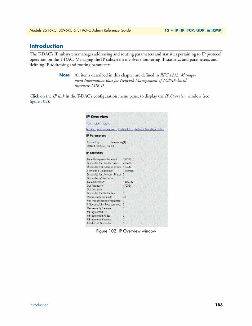
Models 2616RC, 3096RC & 3196RC Admin Reference Guide 12 • IP (IP, TCP, UDP, & ICMP)
IntroductionThe T-DAC’s IP subsystem manages addressing and routing parameters and statistics pertaining to IP protocol operation on the T-DAC. Managing the IP subsystem involves monitoring IP statistics and parameters, and defining IP addressing and routing parameters.
Note All items described in this chapter are defined in RFC 1213: Manage-ment Information Base for Network Management of TCP/IP-based internets: MIB-II.
Click on the IP link in the T-DAC’s configuration menu pane, to display the IP Overview window (see figure 102).
Figure 102. IP Overview window
Introduction 183
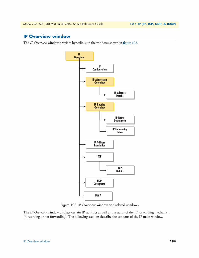
Models 2616RC, 3096RC & 3196RC Admin Reference Guide 12 • IP (IP, TCP, UDP, & ICMP)
IP Overview windowThe IP Overview window provides hyperlinks to the windows shown in figure 103.
Figure 103. IP Overview window and related windows
The IP Overview window displays certain IP statistics as well as the status of the IP forwarding mechanism (forwarding or not forwarding). The following sections describe the contents of the IP main window.
IPConfiguration
IP AddressingOverview
IP AddressDetails
IP AddressTranslation
IP RouteDestination
IP ForwardingTable
IP RoutingOverview
IPOverview
UDPDatagrams
TCPDetails
TCP
ICMP
IP Overview window 184

Models 2616RC, 3096RC & 3196RC Admin Reference Guide 12 • IP (IP, TCP, UDP, & ICMP)
HyperlinksThe IP Overview window provides the following hyperlinks to the windows shown in figure 103. You can use these pages to view and modify the values of certain IP parameters:
• TCP—Clicking the TCP hyperlink displays the TCP Overview window (see section “TCP Overview win-dow” on page 198).
• UDP—Clicking the UDP hyperlink displays the UDP Overview window (see section “UDP Overview window” on page 201).
• ICMP—Clicking the ICMP hyperlink displays the ICMP Overview window (see section “ICMP Overview window” on page 203).
• Modify—Clicking the Modify hyperlink displays the IP Configuration window where you can modify the values of the IP forwarding and time-to-live parameters (see “IP Configuration window” on page 188).
• Addressing Info—Clicking the Addressing Info hyperlink displays the IP Addressing Overview window. This window (see “IP Addressing Overview window” on page 189) displays each IP address and its associated T-DAC interface ID number, and a Details…. for each IP address. The Details hyperlink displays the IP address Details window for that IP address.
• Routing Info—Clicking the Routing Info hyperlink displays IP Routing Overview window. This window displays the defined IP routes table that the T-DAC uses to routing IP datagrams. For each route, the table shows the IP address, subnet mask, next hop router, and interface) You can use this window to add IP routes to the T-DAC’s routing table by defining IP routing parameters (see “IP Routing Overview window” on page 190).
• Address Translation Info—Clicking the Address Translation Info hyperlink displays the IP address transla-tion window where you can view and define the T-DACs physical to logical (MAC to IP) address correla-tions (mappings) (see “IP Address Translation Overview window” on page 196).
IP ParametersThe following sections describe the IP parameters displayed on the IP Overview window.
Forwarding The Forwarding parameter defines whether the T-DAC acts as an IP gateway in respect to the forwarding of datagrams received by, but not addressed to the T-DAC. IP gateways forward datagrams. IP hosts do not for-ward datagrams, except in the case when the host is the source of the datagram.
Note For some managed nodes, this object may take on only a subset of the values possible. Accordingly, it is appropriate for an agent to return a “badValue” response if a management station attempts to change this object to an inappropriate value.
One of the following values may be defined for ipForwarding:
• forwarding(1)—acting as a gateway and will forward IP datagrams to other gateways
• not-forwarding(2)—not acting as a gateway so it will discard IP datagrams destined for other gateways
IP Overview window 185

Models 2616RC, 3096RC & 3196RC Admin Reference Guide 12 • IP (IP, TCP, UDP, & ICMP)
Default Time-To-LiveThe default value inserted into the time-to-live field of the IP header of datagrams originated at the T-DAC, whenever a TTL value is not supplied by the transport layer protocol.
IP StatisticsThe following sections describe the IP statistics displayed on the IP Overview window.
Total Datagrams ReceivedThe total number of input datagrams received from interfaces, including those received in error.
Discarded for Header ErrorsThe number of input datagrams discarded due to errors in their IP headers, including bad checksums, version number mismatch, other format errors, time-to-live exceeded, errors discovered in processing their IP options, and so on.
Discarded for Address ErrorsThe number of input datagrams discarded because the IP address in their IP header’s destination field was not a valid address to be received at the T-DAC. This count includes invalid addresses (e.g., 0.0.0.0) and addresses of unsupported Classes (e.g., Class E). For entities which are not IP Gateways and therefore do not forward datagrams, this counter includes datagrams discarded because the destination address was not a local address.
Forwarded DatagramsThe number of input datagrams for which the T-DAC was not their final IP destination, as a result of which an attempt was made to find a route to forward them to that final destination. In entities which do not act as IP Gateways, this counter will include only those packets which were source-routed via the T-DAC, and the source-route option processing was successful.
Discarded for Unknown ProtosThe number of locally-addressed datagrams received successfully but discarded because of an unknown or unsupported protocol.
Discarded with No ErrorsThe number of input IP datagrams for which no problems were encountered to prevent their continued pro-cessing, but which were discarded (for example, due to lack of buffer space).
Note The Discarded w/No Errors counter does not include any datagrams discarded while awaiting re-assembly.
Total DeliveriesThe total number of input datagrams successfully delivered to IP user-protocols (including ICMP).
Out RequestsThe total number of IP datagrams which local IP user-protocols (including ICMP) supplied to IP in requests for transmission.
IP Overview window 186
Models 2616RC, 3096RC & 3196RC Admin Reference Guide 12 • IP (IP, TCP, UDP, & ICMP)
Note The Out Requests counter does not include any datagrams counted in ipForwDatagrams.
Out DiscardsThe number of output IP datagrams for which no problem was encountered to prevent their transmission to their destination, but which were discarded (e.g., for lack of buffer space).
Note The Out Discards counter would include datagrams counted in ipForwDatagrams if any such packets met this (discretionary) discard criterion.
Discarded for No RoutesThe number of IP datagrams discarded because no route could be found to transmit them to their destination.
Note The Discarded for No Routes counter includes any packets counted in ipForwDatagrams which meet this “no-route” criterion. This includes any datagrams which a host cannot route because all of its default gateways are down.
Reassembly TimeoutThe maximum number of seconds which received fragments are held while they are awaiting reassembly at the T-DAC.
# of Reassembled FragmentsThe number of IP fragments received which needed to be reassembled at the T-DAC.
# Successfully ReassembledThe number of IP datagrams successfully reassembled.
Reassembly FailuresThe number of failures detected by the IP reassembly algorithm (for whatever reason: timed out, errors, etc.).
Note The Reassembly Failures value is not necessarily a count of discarded IP fragments since some algorithms (notably the algorithm in RFC 815) can lose track of the number of fragments by combining them as they are received.
# Fragmented OKThe number of IP datagrams that have been successfully fragmented at the T-DAC.
# Fragmented FailedThe number of IP datagrams that have been discarded because they required fragmenting at the T-DAC, but were not fragmented because their Don’t Fragment option was set.
# Fragments CreatedThe number of IP datagram fragments that have been generated at the T-DAC.
IP Overview window 187
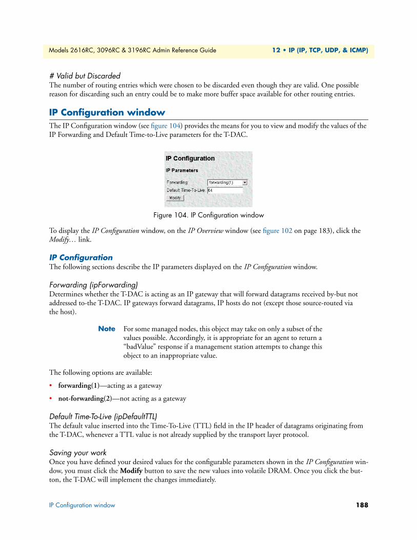
Models 2616RC, 3096RC & 3196RC Admin Reference Guide 12 • IP (IP, TCP, UDP, & ICMP)
# Valid but DiscardedThe number of routing entries which were chosen to be discarded even though they are valid. One possible reason for discarding such an entry could be to make more buffer space available for other routing entries.
IP Configuration windowThe IP Configuration window (see figure 104) provides the means for you to view and modify the values of the IP Forwarding and Default Time-to-Live parameters for the T-DAC.
Figure 104. IP Configuration window
To display the IP Configuration window, on the IP Overview window (see figure 102 on page 183), click the Modify… link.
IP ConfigurationThe following sections describe the IP parameters displayed on the IP Configuration window.
Forwarding (ipForwarding)Determines whether the T-DAC is acting as an IP gateway that will forward datagrams received by-but not addressed to-the T-DAC. IP gateways forward datagrams, IP hosts do not (except those source-routed via the host).
Note For some managed nodes, this object may take on only a subset of the values possible. Accordingly, it is appropriate for an agent to return a “badValue” response if a management station attempts to change this object to an inappropriate value.
The following options are available:
• forwarding(1)—acting as a gateway
• not-forwarding(2)—not acting as a gateway
Default Time-To-Live (ipDefaultTTL)The default value inserted into the Time-To-Live (TTL) field in the IP header of datagrams originating from the T-DAC, whenever a TTL value is not already supplied by the transport layer protocol.
Saving your workOnce you have defined your desired values for the configurable parameters shown in the IP Configuration win-dow, you must click the Modify button to save the new values into volatile DRAM. Once you click the but-ton, the T-DAC will implement the changes immediately.
IP Configuration window 188
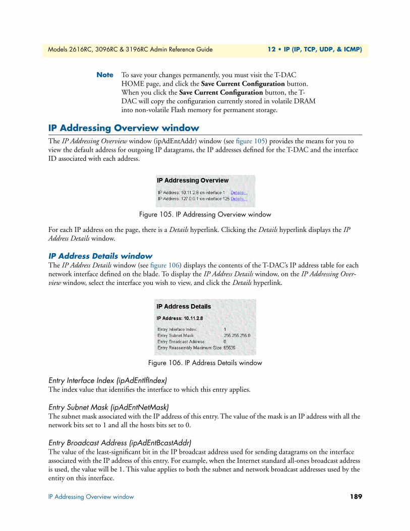
Models 2616RC, 3096RC & 3196RC Admin Reference Guide 12 • IP (IP, TCP, UDP, & ICMP)
Note To save your changes permanently, you must visit the T-DAC HOME page, and click the Save Current Configuration button. When you click the Save Current Configuration button, the T-DAC will copy the configuration currently stored in volatile DRAM into non-volatile Flash memory for permanent storage.
IP Addressing Overview windowThe IP Addressing Overview window (ipAdEntAddr) window (see figure 105) provides the means for you to view the default address for outgoing IP datagrams, the IP addresses defined for the T-DAC and the interface ID associated with each address.
Figure 105. IP Addressing Overview window
For each IP address on the page, there is a Details hyperlink. Clicking the Details hyperlink displays the IP Address Details window.
IP Address Details windowThe IP Address Details window (see figure 106) displays the contents of the T-DAC’s IP address table for each network interface defined on the blade. To display the IP Address Details window, on the IP Addressing Over-view window, select the interface you wish to view, and click the Details hyperlink.
Figure 106. IP Address Details window
Entry Interface Index (ipAdEntIfIndex) The index value that identifies the interface to which this entry applies.
Entry Subnet Mask (ipAdEntNetMask) The subnet mask associated with the IP address of this entry. The value of the mask is an IP address with all the network bits set to 1 and all the hosts bits set to 0.
Entry Broadcast Address (ipAdEntBcastAddr) The value of the least-significant bit in the IP broadcast address used for sending datagrams on the interface associated with the IP address of this entry. For example, when the Internet standard all-ones broadcast address is used, the value will be 1. This value applies to both the subnet and network broadcast addresses used by the entity on this interface.
IP Addressing Overview window 189
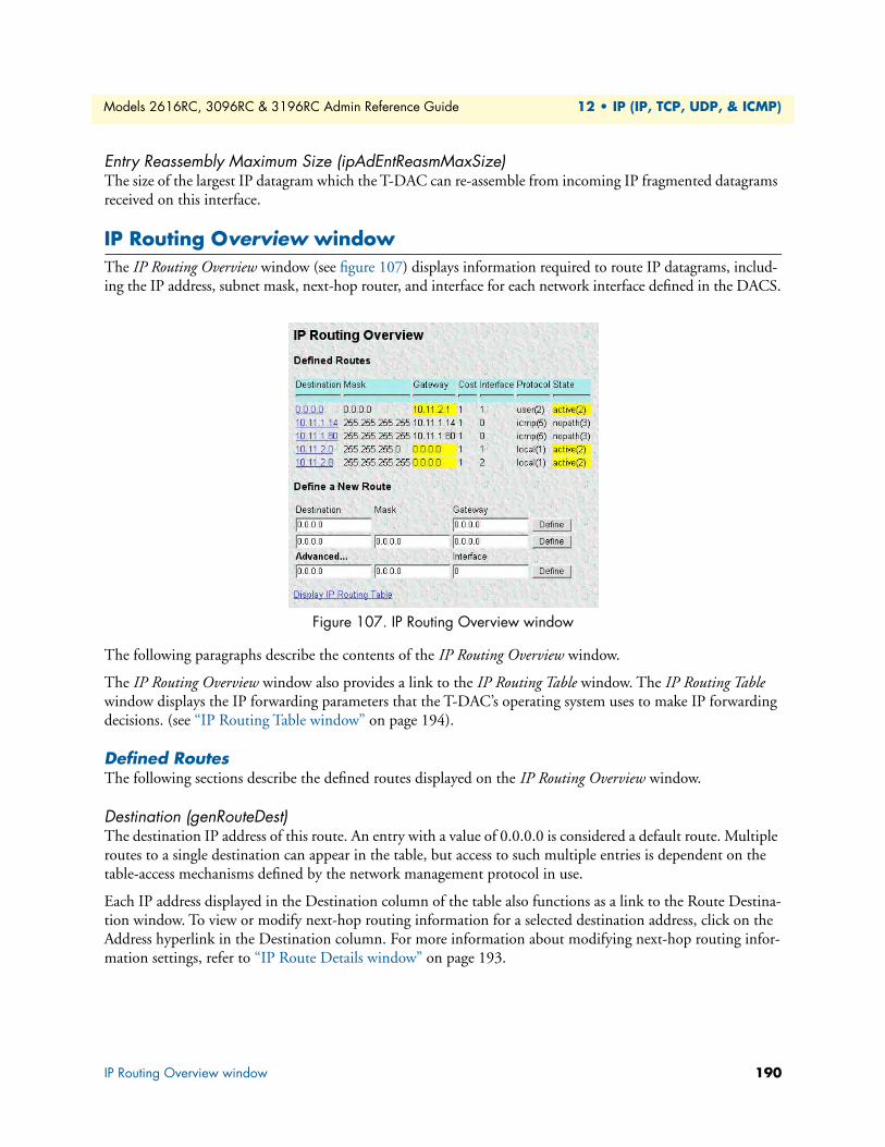
Models 2616RC, 3096RC & 3196RC Admin Reference Guide 12 • IP (IP, TCP, UDP, & ICMP)
Entry Reassembly Maximum Size (ipAdEntReasmMaxSize) The size of the largest IP datagram which the T-DAC can re-assemble from incoming IP fragmented datagrams received on this interface.
IP Routing Overview windowThe IP Routing Overview window (see figure 107) displays information required to route IP datagrams, includ-ing the IP address, subnet mask, next-hop router, and interface for each network interface defined in the DACS.
Figure 107. IP Routing Overview window
The following paragraphs describe the contents of the IP Routing Overview window.
The IP Routing Overview window also provides a link to the IP Routing Table window. The IP Routing Table window displays the IP forwarding parameters that the T-DAC’s operating system uses to make IP forwarding decisions. (see “IP Routing Table window” on page 194).
Defined RoutesThe following sections describe the defined routes displayed on the IP Routing Overview window.
Destination (genRouteDest)The destination IP address of this route. An entry with a value of 0.0.0.0 is considered a default route. Multiple routes to a single destination can appear in the table, but access to such multiple entries is dependent on the table-access mechanisms defined by the network management protocol in use.
Each IP address displayed in the Destination column of the table also functions as a link to the Route Destina-tion window. To view or modify next-hop routing information for a selected destination address, click on the Address hyperlink in the Destination column. For more information about modifying next-hop routing infor-mation settings, refer to “IP Route Details window” on page 193.
IP Routing Overview window 190
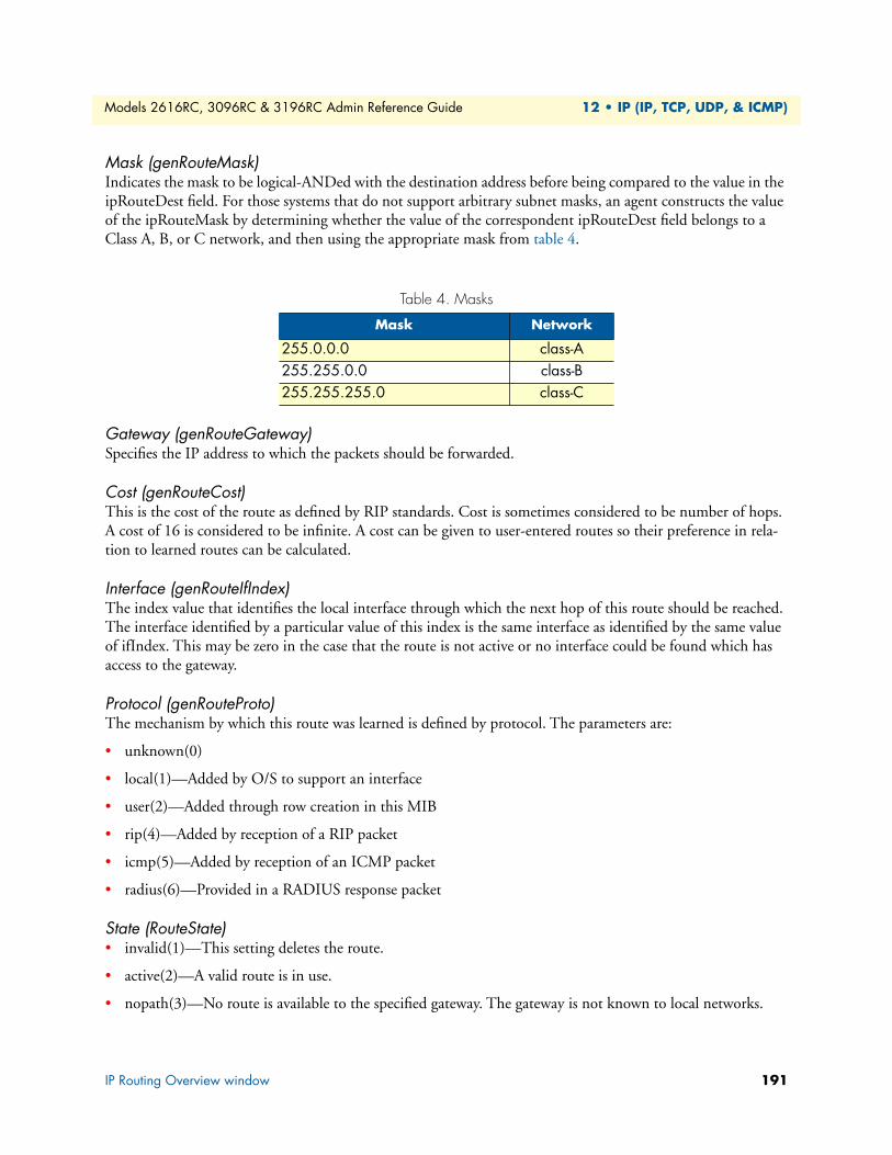
Models 2616RC, 3096RC & 3196RC Admin Reference Guide 12 • IP (IP, TCP, UDP, & ICMP)
Mask (genRouteMask)Indicates the mask to be logical-ANDed with the destination address before being compared to the value in the ipRouteDest field. For those systems that do not support arbitrary subnet masks, an agent constructs the value of the ipRouteMask by determining whether the value of the correspondent ipRouteDest field belongs to a Class A, B, or C network, and then using the appropriate mask from table 4.
Gateway (genRouteGateway)Specifies the IP address to which the packets should be forwarded.
Cost (genRouteCost)This is the cost of the route as defined by RIP standards. Cost is sometimes considered to be number of hops. A cost of 16 is considered to be infinite. A cost can be given to user-entered routes so their preference in rela-tion to learned routes can be calculated.
Interface (genRouteIfIndex)The index value that identifies the local interface through which the next hop of this route should be reached. The interface identified by a particular value of this index is the same interface as identified by the same value of ifIndex. This may be zero in the case that the route is not active or no interface could be found which has access to the gateway.
Protocol (genRouteProto)The mechanism by which this route was learned is defined by protocol. The parameters are:
• unknown(0)
• local(1)—Added by O/S to support an interface
• user(2)—Added through row creation in this MIB
• rip(4)—Added by reception of a RIP packet
• icmp(5)—Added by reception of an ICMP packet
• radius(6)—Provided in a RADIUS response packet
State (RouteState)• invalid(1)—This setting deletes the route.
• active(2)—A valid route is in use.
• nopath(3)—No route is available to the specified gateway. The gateway is not known to local networks.
Table 4. Masks
Mask Network
255.0.0.0 class-A255.255.0.0 class-B255.255.255.0 class-C
IP Routing Overview window 191
Models 2616RC, 3096RC & 3196RC Admin Reference Guide 12 • IP (IP, TCP, UDP, & ICMP)
• agedout(4)—Invalid route (soon to be removed).
• costly(5)—A valid route, but not in use because of it’s higher cost.
Defined RoutesThis portion of the IP Routing Information window is where you can add a new route to the IP Routing Over-view window. Fill in the Destination (genRouteDest), Mask (genRouteMask), and Gateway (genRouteGate-way) information, then click the Define button.
Destination (ipRouteDest)The destination IP address of this route. An entry with a value of 0.0.0.0 is considered a default route. Multiple routes to a single destination can appear in the table, but access to such multiple entries is dependent on the table-access mechanisms defined by the network management protocol in use.
Note To view or modify the next-hop routing parameters for a single desti-nation address, choose an address you wish to view under the Desti-nation column, then click the hyperlink to display the IP Route Details window (see “IP Route Details window” on page 193 for details).
Mask (ipRouteMask)Indicates the mask to be logical-ANDed with the destination address before being compared to the value in the ipRouteDest field. For those systems that do not support arbitrary subnet masks, an agent constructs the value of the ipRouteMask by determining whether the value of the correspondent ipRouteDest field belongs to a Class A, B, or C network, and then using the appropriate mask from Table 4 on page 191.
Gateway (genRouteGateway)Specifies the IP address to which the packets should be forwarded.
Advanced…Enables a route to be attached to an interface. Packets to a network will be routed to that interface, allowing the gateway IP address to be dynamic. Fill in the Destination (genRouteDest), Mask (genRouteMask), and Interface (genRouteIfIndex) information, then click the Define button.
Destination (ipRouteDest)The destination IP address of this route. An entry with a value of 0.0.0.0 is considered a default route. Multiple routes to a single destination can appear in the table, but access to such multiple entries is dependent on the table-access mechanisms defined by the network management protocol in use.
Mask (ipRouteMask)Indicates the mask to be logical-ANDed with the destination address before being compared to the value in the ipRouteDest field. For those systems that do not support arbitrary subnet masks, an agent constructs the value of the ipRouteMask by determining whether the value of the correspondent ipRouteDest field belongs to a Class A, B, or C network, and then using the appropriate mask from Table 4 on page 191.
Interface (genRouteIfIndex)Specifies the IP address to which the packets should be forwarded.
IP Routing Overview window 192
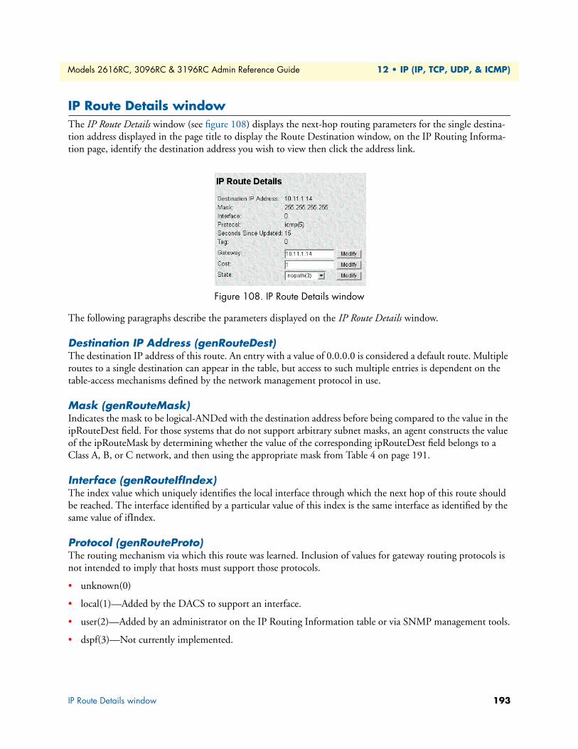
Models 2616RC, 3096RC & 3196RC Admin Reference Guide 12 • IP (IP, TCP, UDP, & ICMP)
IP Route Details windowThe IP Route Details window (see figure 108) displays the next-hop routing parameters for the single destina-tion address displayed in the page title to display the Route Destination window, on the IP Routing Informa-tion page, identify the destination address you wish to view then click the address link.
Figure 108. IP Route Details window
The following paragraphs describe the parameters displayed on the IP Route Details window.
Destination IP Address (genRouteDest)The destination IP address of this route. An entry with a value of 0.0.0.0 is considered a default route. Multiple routes to a single destination can appear in the table, but access to such multiple entries is dependent on the table-access mechanisms defined by the network management protocol in use.
Mask (genRouteMask)Indicates the mask to be logical-ANDed with the destination address before being compared to the value in the ipRouteDest field. For those systems that do not support arbitrary subnet masks, an agent constructs the value of the ipRouteMask by determining whether the value of the corresponding ipRouteDest field belongs to a Class A, B, or C network, and then using the appropriate mask from Table 4 on page 191.
Interface (genRouteIfIndex)The index value which uniquely identifies the local interface through which the next hop of this route should be reached. The interface identified by a particular value of this index is the same interface as identified by the same value of ifIndex.
Protocol (genRouteProto)The routing mechanism via which this route was learned. Inclusion of values for gateway routing protocols is not intended to imply that hosts must support those protocols.
• unknown(0)
• local(1)—Added by the DACS to support an interface.
• user(2)—Added by an administrator on the IP Routing Information table or via SNMP management tools.
• dspf(3)—Not currently implemented.
IP Route Details window 193

Models 2616RC, 3096RC & 3196RC Admin Reference Guide 12 • IP (IP, TCP, UDP, & ICMP)
• rip(4)—Learned via reception of RIP packet.
• icmp(5)—Learned via reception of ICMP packet.
Seconds Since Updated (genRouteAge) The number of seconds since this route was last updated or otherwise determined to be correct.
Tag (genRouteTag)An identifier associated with the route. This can have different meanings depending on the protocol. For exam-ple, this gives the tag that was passed with a learned RIP route.
Gateway (genRouteGateway)Specifies the IP address to which the packets should be forwarded. Type the address, then click the Modify button next to the Gateway text box.
Cost (genRouteCost)This is the cost of the route as defined by RIP standards. Cost is sometimes considered to be number of hops. A cost of 16 is considered to be infinite. A cost can be given to user-entered routes so their preference in rela-tion to learned routes can be calculated. Type the cost value, then click the Modify button next to the Cost text box.
State (genRouteState)Defines the state which a route may be in during its lifetime.
• invalid(1)—This setting deletes the route.
• active(2)—A valid route is in use.
• nopath(3)—No route is available to the specified gateway. The gateway is not known to local networks.
• agedout(4)—Invalid route (soon to be removed).
• costly(5)—A valid route, but not in use because of it’s higher cost.
Select the desired state from the menu, then click the Modify button next to the State menu.
IP Routing Table windowThe IP Routing Table window (see figure 109) displays the IP forwarding parameters for all routes in the T-DAC’s IP Routing table. To display the IP Routing Table window, on the IP Route Overview window (see figure 107 on page 190), click the Display IP Routing Table link.
Figure 109. IP Routing Table window
IP Routing Table window 194
Models 2616RC, 3096RC & 3196RC Admin Reference Guide 12 • IP (IP, TCP, UDP, & ICMP)
Destination (ipRouteDest)The destination IP address of this route. An entry with a value of 0.0.0.0 is considered a default route. Multiple routes to a single destination can appear in the table, but access to such multiple entries is dependent on the table-access mechanisms defined by the network management protocol in use.
Mask (ipRouteMask)Indicates the mask to be logical-ANDed with the destination address before being compared to the value in the ipRouteDest field. For those systems that do not support arbitrary subnet masks, an agent constructs the value of the ipRouteMask by determining whether the value of the correspondent ipRouteDest field belongs to a Class A, B, or C network, and then using the appropriate mask from Table 4 on page 191.
Next Hop (ipRouteNextHop) The IP address of the next hop of this route. (In the case of a route bound to an interface which is realized via a broadcast media, the value of this field is the agent's IP address on that interface.)
Interface (ipRouteIfIndex)The index value that identifies the local interface through which the next hop of this route should be reached. The interface identified by a particular value of this index is the same interface as identified by the same value of ifIndex.
Type (ipRouteType) One of the following route types:
• other(1)—none of the following
• invalid(2)—an invalidated route
• direct(3)—route to directly connected (sub-)network
• indirect(4)—route to a non-local host/network/sub-network
Note The values direct(3) and indirect(4) refer to the notion of direct and indirect routing in the IP architecture. Setting this object to the value invalid(2) has the effect of invalidating the corresponding entry in the ipRouteTable object. That is, it effectively disassociates the destination identified with said entry from the route identified with said entry. It is an implementation-specific matter as to whether the agent removes an invalidated entry from the table. Accordingly, management stations must be prepared to receive tabular information from agents that corre-sponds to entries not currently in use. Proper interpretation of such entries requires examination of the relevant ipRouteType object.
Protocol (ipRouteProto)The routing mechanism via which this route was learned. Inclusion of values for gateway routing protocols is not intended to imply that hosts must support those protocols.
• unknown(0)
• local(1)—Added by the DACS to support an interface.
IP Routing Table window 195
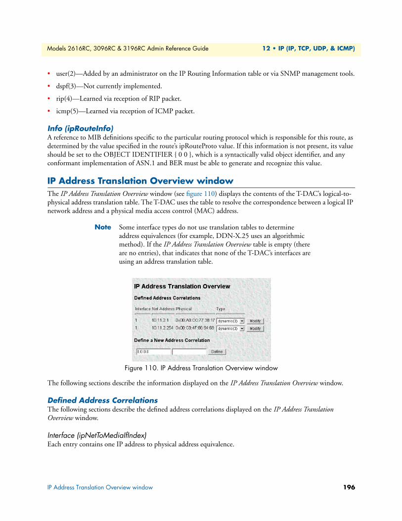
Models 2616RC, 3096RC & 3196RC Admin Reference Guide 12 • IP (IP, TCP, UDP, & ICMP)
• user(2)—Added by an administrator on the IP Routing Information table or via SNMP management tools.
• dspf(3)—Not currently implemented.
• rip(4)—Learned via reception of RIP packet.
• icmp(5)—Learned via reception of ICMP packet.
Info (ipRouteInfo) A reference to MIB definitions specific to the particular routing protocol which is responsible for this route, as determined by the value specified in the route’s ipRouteProto value. If this information is not present, its value should be set to the OBJECT IDENTIFIER { 0 0 }, which is a syntactically valid object identifier, and any conformant implementation of ASN.1 and BER must be able to generate and recognize this value.
IP Address Translation Overview windowThe IP Address Translation Overview window (see figure 110) displays the contents of the T-DAC’s logical-to-physical address translation table. The T-DAC uses the table to resolve the correspondence between a logical IP network address and a physical media access control (MAC) address.
Note Some interface types do not use translation tables to determine address equivalences (for example, DDN-X.25 uses an algorithmic method). If the IP Address Translation Overview table is empty (there are no entries), that indicates that none of the T-DAC’s interfaces are using an address translation table.
Figure 110. IP Address Translation Overview window
The following sections describe the information displayed on the IP Address Translation Overview window.
Defined Address CorrelationsThe following sections describe the defined address correlations displayed on the IP Address Translation Overview window.
Interface (ipNetToMediaIfIndex) Each entry contains one IP address to physical address equivalence.
IP Address Translation Overview window 196
Models 2616RC, 3096RC & 3196RC Admin Reference Guide 12 • IP (IP, TCP, UDP, & ICMP)
Net Address (ipNetToMediaNetAddress) The IP address corresponding to the media-dependent physical address.
Physical (ipNetToMediaPhysAddress) The media-dependent physical address.
Type (ipNetToMediaType) The type of mapping. Setting this object to the value invalid(2) has the effect of invalidating the corresponding entry in the ipNetToMediaTable. That is, it effectively disassociates the interface identified with said entry from the mapping identified with said entry. It is an implementation-specific matter as to whether the agent removes an invalidated entry from the table. Accordingly, management stations must be prepared to receive tabular information from agents that corresponds to entries not currently in use. Proper interpretation of such entries requires examination of the relevant ipNetToMediaType object.
• other(1)-none of the following
• invalid(2)-an invalidated mapping
• dynamic(3)
• static(4)
Define a New Address CorrelationDo the following to define a new address correlation:
1. Type an IP address in the left text box located under the Define a New Address Correlation heading (see figure 110 on page 196).
2. Type a MAC address in the right text box.
3. Click the Define button to activate the new settings.
IP Address Translation Overview window 197
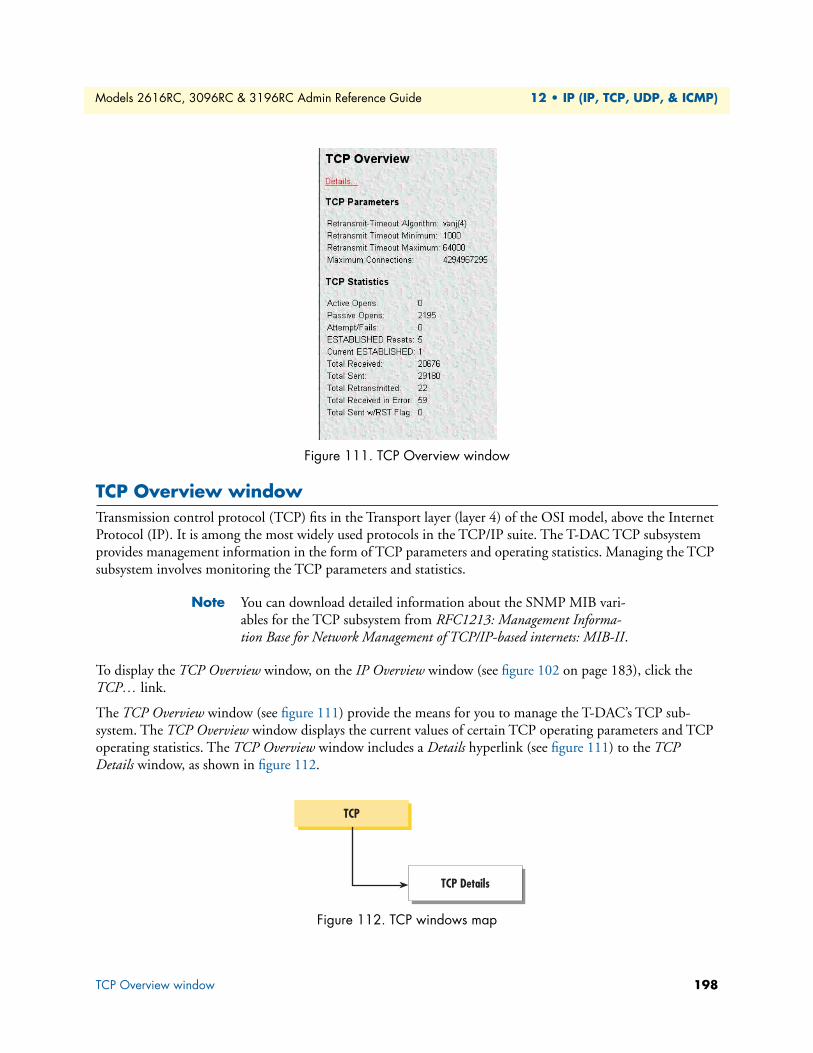
Models 2616RC, 3096RC & 3196RC Admin Reference Guide 12 • IP (IP, TCP, UDP, & ICMP)
Figure 111. TCP Overview window
TCP Overview windowTransmission control protocol (TCP) fits in the Transport layer (layer 4) of the OSI model, above the Internet Protocol (IP). It is among the most widely used protocols in the TCP/IP suite. The T-DAC TCP subsystem provides management information in the form of TCP parameters and operating statistics. Managing the TCP subsystem involves monitoring the TCP parameters and statistics.
Note You can download detailed information about the SNMP MIB vari-ables for the TCP subsystem from RFC1213: Management Informa-tion Base for Network Management of TCP/IP-based internets: MIB-II.
To display the TCP Overview window, on the IP Overview window (see figure 102 on page 183), click the TCP… link.
The TCP Overview window (see figure 111) provide the means for you to manage the T-DAC’s TCP sub-system. The TCP Overview window displays the current values of certain TCP operating parameters and TCP operating statistics. The TCP Overview window includes a Details hyperlink (see figure 111) to the TCP Details window, as shown in figure 112.
Figure 112. TCP windows map
TCP
TCP Details
TCP Overview window 198
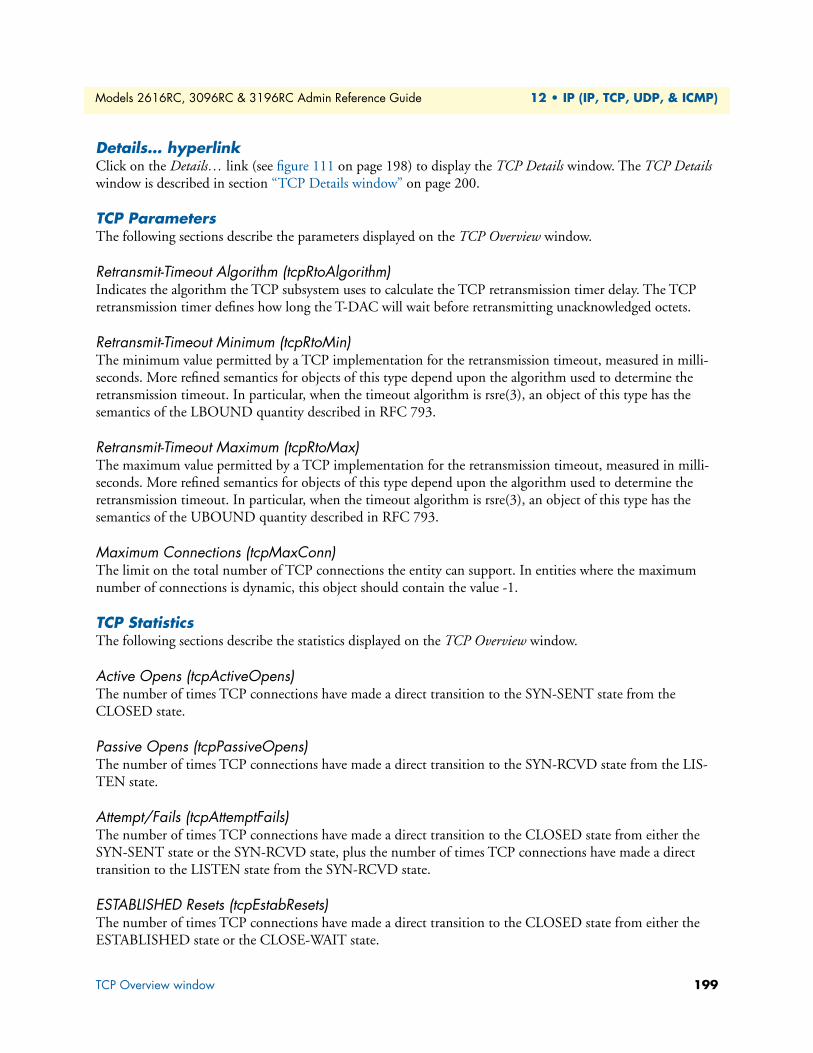
Models 2616RC, 3096RC & 3196RC Admin Reference Guide 12 • IP (IP, TCP, UDP, & ICMP)
Details… hyperlinkClick on the Details… link (see figure 111 on page 198) to display the TCP Details window. The TCP Details window is described in section “TCP Details window” on page 200.
TCP Parameters The following sections describe the parameters displayed on the TCP Overview window.
Retransmit-Timeout Algorithm (tcpRtoAlgorithm)Indicates the algorithm the TCP subsystem uses to calculate the TCP retransmission timer delay. The TCP retransmission timer defines how long the T-DAC will wait before retransmitting unacknowledged octets.
Retransmit-Timeout Minimum (tcpRtoMin)The minimum value permitted by a TCP implementation for the retransmission timeout, measured in milli-seconds. More refined semantics for objects of this type depend upon the algorithm used to determine the retransmission timeout. In particular, when the timeout algorithm is rsre(3), an object of this type has the semantics of the LBOUND quantity described in RFC 793.
Retransmit-Timeout Maximum (tcpRtoMax)The maximum value permitted by a TCP implementation for the retransmission timeout, measured in milli-seconds. More refined semantics for objects of this type depend upon the algorithm used to determine the retransmission timeout. In particular, when the timeout algorithm is rsre(3), an object of this type has the semantics of the UBOUND quantity described in RFC 793.
Maximum Connections (tcpMaxConn)The limit on the total number of TCP connections the entity can support. In entities where the maximum number of connections is dynamic, this object should contain the value -1.
TCP Statistics The following sections describe the statistics displayed on the TCP Overview window.
Active Opens (tcpActiveOpens)The number of times TCP connections have made a direct transition to the SYN-SENT state from the CLOSED state.
Passive Opens (tcpPassiveOpens)The number of times TCP connections have made a direct transition to the SYN-RCVD state from the LIS-TEN state.
Attempt/Fails (tcpAttemptFails)The number of times TCP connections have made a direct transition to the CLOSED state from either the SYN-SENT state or the SYN-RCVD state, plus the number of times TCP connections have made a direct transition to the LISTEN state from the SYN-RCVD state.
ESTABLISHED Resets (tcpEstabResets)The number of times TCP connections have made a direct transition to the CLOSED state from either the ESTABLISHED state or the CLOSE-WAIT state.
TCP Overview window 199
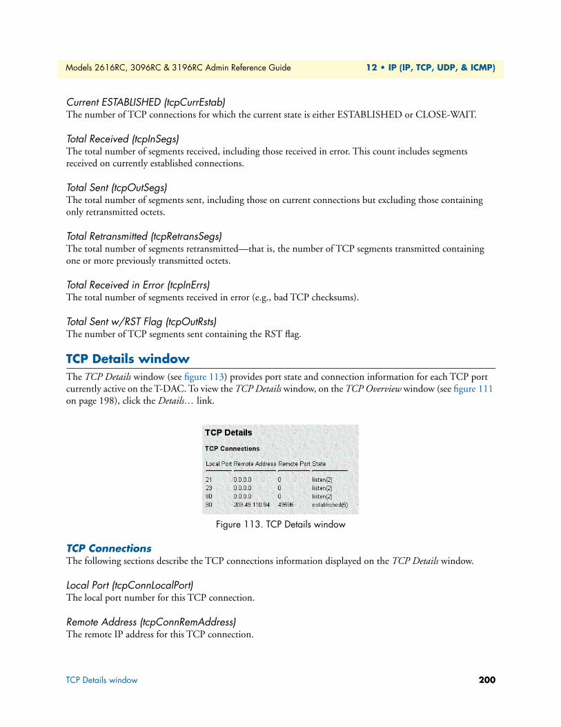
Models 2616RC, 3096RC & 3196RC Admin Reference Guide 12 • IP (IP, TCP, UDP, & ICMP)
Current ESTABLISHED (tcpCurrEstab)The number of TCP connections for which the current state is either ESTABLISHED or CLOSE-WAIT.
Total Received (tcpInSegs)The total number of segments received, including those received in error. This count includes segments received on currently established connections.
Total Sent (tcpOutSegs)The total number of segments sent, including those on current connections but excluding those containing only retransmitted octets.
Total Retransmitted (tcpRetransSegs)The total number of segments retransmitted—that is, the number of TCP segments transmitted containing one or more previously transmitted octets.
Total Received in Error (tcpInErrs)The total number of segments received in error (e.g., bad TCP checksums).
Total Sent w/RST Flag (tcpOutRsts)The number of TCP segments sent containing the RST flag.
TCP Details windowThe TCP Details window (see figure 113) provides port state and connection information for each TCP port currently active on the T-DAC. To view the TCP Details window, on the TCP Overview window (see figure 111 on page 198), click the Details… link.
Figure 113. TCP Details window
TCP ConnectionsThe following sections describe the TCP connections information displayed on the TCP Details window.
Local Port (tcpConnLocalPort)The local port number for this TCP connection.
Remote Address (tcpConnRemAddress)The remote IP address for this TCP connection.
TCP Details window 200
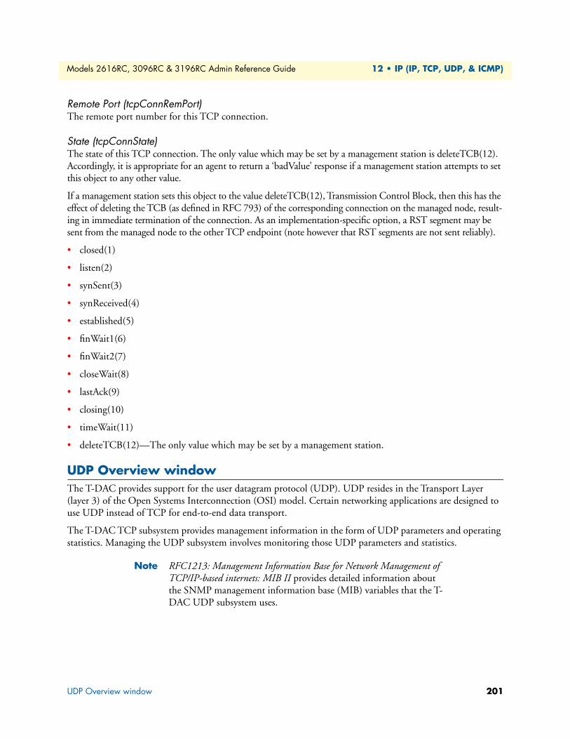
Models 2616RC, 3096RC & 3196RC Admin Reference Guide 12 • IP (IP, TCP, UDP, & ICMP)
Remote Port (tcpConnRemPort)The remote port number for this TCP connection.
State (tcpConnState)The state of this TCP connection. The only value which may be set by a management station is deleteTCB(12). Accordingly, it is appropriate for an agent to return a ‘badValue’ response if a management station attempts to set this object to any other value.
If a management station sets this object to the value deleteTCB(12), Transmission Control Block, then this has the effect of deleting the TCB (as defined in RFC 793) of the corresponding connection on the managed node, result-ing in immediate termination of the connection. As an implementation-specific option, a RST segment may be sent from the managed node to the other TCP endpoint (note however that RST segments are not sent reliably).
• closed(1)
• listen(2)
• synSent(3)
• synReceived(4)
• established(5)
• finWait1(6)
• finWait2(7)
• closeWait(8)
• lastAck(9)
• closing(10)
• timeWait(11)
• deleteTCB(12)—The only value which may be set by a management station.
UDP Overview windowThe T-DAC provides support for the user datagram protocol (UDP). UDP resides in the Transport Layer (layer 3) of the Open Systems Interconnection (OSI) model. Certain networking applications are designed to use UDP instead of TCP for end-to-end data transport.
The T-DAC TCP subsystem provides management information in the form of UDP parameters and operating statistics. Managing the UDP subsystem involves monitoring those UDP parameters and statistics.
Note RFC1213: Management Information Base for Network Management of TCP/IP-based internets: MIB II provides detailed information about the SNMP management information base (MIB) variables that the T-DAC UDP subsystem uses.
UDP Overview window 201
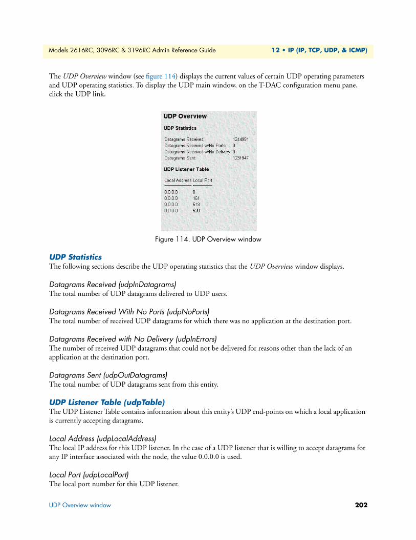
Models 2616RC, 3096RC & 3196RC Admin Reference Guide 12 • IP (IP, TCP, UDP, & ICMP)
The UDP Overview window (see figure 114) displays the current values of certain UDP operating parameters and UDP operating statistics. To display the UDP main window, on the T-DAC configuration menu pane, click the UDP link.
Figure 114. UDP Overview window
UDP StatisticsThe following sections describe the UDP operating statistics that the UDP Overview window displays.
Datagrams Received (udpInDatagrams)The total number of UDP datagrams delivered to UDP users.
Datagrams Received With No Ports (udpNoPorts)The total number of received UDP datagrams for which there was no application at the destination port.
Datagrams Received with No Delivery (udpInErrors)The number of received UDP datagrams that could not be delivered for reasons other than the lack of an application at the destination port.
Datagrams Sent (udpOutDatagrams)The total number of UDP datagrams sent from this entity.
UDP Listener Table (udpTable)The UDP Listener Table contains information about this entity’s UDP end-points on which a local application is currently accepting datagrams.
Local Address (udpLocalAddress)The local IP address for this UDP listener. In the case of a UDP listener that is willing to accept datagrams for any IP interface associated with the node, the value 0.0.0.0 is used.
Local Port (udpLocalPort)The local port number for this UDP listener.
UDP Overview window 202
Models 2616RC, 3096RC & 3196RC Admin Reference Guide 12 • IP (IP, TCP, UDP, & ICMP)
ICMP Overview windowWhen networking problems or undesirable conditions occur, the ICMP protocol is used for communicating con-trol or error information plus testing. The statistics listed on the T-DAC ICMP window (see figure 115) comprise those contained in RFC 792—Internet Control Message Protocol (ICMP). Implementation of the ICMP group is mandatory for all TCP/IP networks. RFC 1312—ICMP Group of MIB-II Variables—provides the definitions of these variables. It is important to remember that any RFC can be superseded by a newer version.
Figure 115. ICMP Overview window
To display the ICMP Overview window, on the T-DAC configuration menu pane, click the ICMP hyperlink
The ICMP Overview window provides the means for you to manage the T-DAC’s ICMP subsystem. Managing the T-DAC’s ICMP subsystem involves monitoring ICMP statistics, and defining whether the T-DAC will receive or block ICMP Redirect messages sent from gateway routers and/or hosts.
ICMP ParametersThe ICMP Parameters section of the ICMP Overview window (see figure 115) is where you can define whether the T-DAC will receive or block ICMP Redirect messages sent from gateway routers and/or hosts.
ICMP Redirects (boxBlockIcmpRedirects)The two options for “Block ICMP Redirects” either allow the reception of ICMP Redirect messages (allowRedirects(0)) or block the reception of ICMP Redirect messages (stopRedirects(1)). The recommended
ICMP Overview window 203
Models 2616RC, 3096RC & 3196RC Admin Reference Guide 12 • IP (IP, TCP, UDP, & ICMP)
configuration is to block the ICMP redirect messages because in some instances they could alter the routing table with undesirable effects, which is considered a breach of security.
The options are:
• allowRedirects(0)
• stopRedirects(1)
After making your selection, click the Modify button to apply the changes.
ICMP StatisticsThe ICMP Statistics section of the ICMP Overview window (see figure 115 on page 203) displays the ICMP message counters. ICMP messages are displayed in the window table as columns comprising two types of messages:
• Messages received by the T-DAC (InMibVariable)
• Messages sent by the T-DAC (OutMibVariable)
The numbers following the parameters can be a good source of what is happening on the network to point out potential problems. Both gateways (routers) and hosts can send ICMP messages.
Total ICMP Datagrams Received (icmpInMsgs)The total number of ICMP messages which the T-DAC has received.
Note This counter includes all those counted by icmpInErrors (see “w/Errors (icmpInErrors, icmpOutErrors)”).
Total ICMP Datagrams Sent (imcpOutMsgs)Similar to icmpInMsgs, Total Sent represents the total number of ICMP messages which the T-DAC has attempted to send. This variable includes all ICMP messages counted by icmpOutErrors (see “w/Errors (icmp-InErrors, icmpOutErrors)”).
w/Errors (icmpInErrors, icmpOutErrors)The number of ICMP messages which the T-DAC received/sent but having ICMP-specific errors (for example, bad ICMP checksums, bad length, or non-routable errors).
Destinations Unreachable (IcmpInDestUnreachs, IcmpOutDestUnreachs)The number of ICMP destination unreachable messages received/sent. For instance, if the information in a gateway’s routing table determines that the network specified in a packet is unreachable, the gateway will send back an ICMP message stating that the network is unreachable. The following conditions will send back an unreachable message:
• The network is unreachable
• The host is unreachable
• The protocol is not available to the network
ICMP Overview window 204
Models 2616RC, 3096RC & 3196RC Admin Reference Guide 12 • IP (IP, TCP, UDP, & ICMP)
• The port on the host is unavailable; a specified source route failed
• A packet must be fragmented (that is, broken up into two or more packets) but the packet was sent anyway with instructions not to be fragmented.
Times Exceeded (icmpInTimeExcds, icmpOutTimeExcds)The number of ICMP time exceeded messages received/sent. Each time a packet passes through a gateway, that gateway reduces the time-to-live (TTL) field by one. The default starting number is defined under the IP sec-tion. If the gateway processing a packet finds that the TTL field is zero it will discard the packet and send the ICMP time exceeded message. Time exceeded will also be incremented when a host which is reassembling a fragmented packet cannot complete the reassembly due to missing packets within its time limit. In this case, ICMP will discard the packet and send the time exceeded message.
Parameter Problems (icmpInParmProbs, icmpOutParmProbs)The number of ICMP parameter problem messages received/sent. If while processing a packet, a gateway or host finds a problem with one or more of the IP header parameters which prohibits further processing, the gat- way or host will discard the packet and return an ICMP parameter problem message. One potential source of this problem may be with incorrect or invalid arguments in an option. ICMP sends the parameter problems message if the gateway or host has discarded the whole packet.
Source Quenchs (icmpInSrcQuenchs, icmpOutSrcQuenchs)The number of ICMP source quench messages received/sent. A gateway will discard packets if it cannot allo-cate the resources, such as buffer space, to process the packet. If a gateway discards the packet, it will send an ICMP source quench message back to the sending device. A host may send this messages if packets arrive too fast to be processed or if there is network congestion. The source quench message is a request to reduce the rate at which the source is sending traffic. If the T-DAC receives a source quench, it will wait for acknowledgement of all outstanding packets before sending more packets to the remote destination. Then it will begin sending out packets at an increasing rate until the connection is restored to standard operating conditions.
Redirects (icmpInRedirects, icmpOutRedirects)The number of ICMP redirect messages received/sent. A gateway sends a redirect message to a host if the net- work gateways find a shorter route to the destination through another gateway.
Echos (icmpInEchos, icmpOutEchos)The number of ICMP echo request messages received/send. The ICMP echo is used whenever one uses the diagnostic tool ping. Ping is used to test connectivity with a remote host by sending regular ICMP echo request packets and then waiting for a reply. Received echos (icmpInEchos) will increment when the T-DAC is pinged.
Echo Replys (icmpInEchoReps, icmpOutEchoReps)The number of ICMP echo reply messages received/sent. An echo reply is a response to an echo request. Send echos (icmpOutEchos) will increment when the T-DAC sends an echo reply message in response to a ping.
Time Stamps (icmpInTimestamps, icmpInTimestamps)The number of ICMP time stamp messages received/sent. Time stamp and time stamp replies were originally designed into the ICMP facility to allow network clock synchronization. Subsequently, a new protocol—Net- work time protocol (NTP) has taken over this function. Normally, this number will be zero.
ICMP Overview window 205
Models 2616RC, 3096RC & 3196RC Admin Reference Guide 12 • IP (IP, TCP, UDP, & ICMP)
Time Stamp Replys (icmpInTimestampsReps) (icmpOutTimestampsReps)The number of ICMP timestamp reply messages received/sent. This message is part of a time stamp (see “Time Stamps (icmpInTimestamps, icmpInTimestamps)”) request. Normally, this number will be zero.
Address Mask Requests (icmpInAddrMasks) (icmpOutAddrMasks)The number of ICMP address mask request messages received/sent. This message is generally used for diskless workstations which use this request at boot time to obtain their subnet mask. This number will increase if there are hosts on the network which broadcast these requests.
Address Mask Replys (icmpInAddrMasksReps) (icmpOutAddrMasksReps)The number of ICMP address mask reply messages received/sent. Normally, this number will be zero.
ICMP Overview window 206

Chapter 13 IP Filtering
Chapter contentsIntroduction ........................................................................................................................................................208IP Filtering Overview window.............................................................................................................................208
Defined Filters ..............................................................................................................................................208Define a New Filter ......................................................................................................................................208
Defining a new filter ...............................................................................................................................209Deleting a filter .......................................................................................................................................209
IP Filter Configuration window...........................................................................................................................209Name (filterIpName) ....................................................................................................................................209Direction (filterIpDirection) .........................................................................................................................210Action (filterIpAction) ..................................................................................................................................210Source IP ......................................................................................................................................................210
Comparison (filterIpSourceAddressCmp) ................................................................................................210Address (filterIpSourceIp) .......................................................................................................................211Mask (filterIpSourceMask) ......................................................................................................................211
Destination IP ..............................................................................................................................................211Comparison (filterIpDestinationAddressCmp) ........................................................................................211Address(filterIpDestinationIp) .................................................................................................................211Mask(filterIpDestinationMask) ...............................................................................................................211
Source Port ...................................................................................................................................................211Comparison (filterIpSourcePortCmp) .....................................................................................................211Port (filterIpSourcePort) .........................................................................................................................211
Destination Port ...........................................................................................................................................212Comparison (filterIpDestinationPortCmp) .............................................................................................212Port (filterIpDestinationPort) ..................................................................................................................212
Protocol (filterIpProtocol) .............................................................................................................................212TCP Established (filterIpTcpEstablished) .....................................................................................................212Deleting a filter .............................................................................................................................................212
An example of using a filter .................................................................................................................................212
207

Models 2616RC, 3096RC & 3196RC Admin Reference Guide 13 • IP Filtering
IntroductionThe access server software provides an IP filtering system that enables you to set up security as well as to provi-sion services for selected customers. While IP filters are typically thought of as a security measure, many pro-viders wish to limit some services a customer may have access to. These could include such things as limited access only to an e-mail server or proxy server. IP filters also include the ability to encapsulate all packets received on the specified dialup link in an extra IP header using RFC 2003. This would allow packets on a dial-up link to be tunneled to a specific host.
Each filter is a defined list of parameters based upon attributes in the IP, TCP, and UDP headers. There are two major steps to filter creation: first defining the filter, then applying it to a user connection. The same filter can be shared by several users.
The T-DAC enables 20 separate filters to be defined, of which up to 10 can be used on a single user connec-tion. A single filter can be assigned to a user via the Static Users Authentication. Multiple filters can be assigned by using the RADIUS Filter-Id attribute.
Filters can be configured with default settings that are used for all dial-in sessions. If any filters are applied through either RADIUS or the Static User filter parameter, then all of the dial-in defaults will be disabled and only the specified filters will be applied.
IP Filtering Overview windowClick on IP Filtering under the Configuration Menu to display the IP Filtering Overview window (see figure 116). The following sections describe each of the parameters found in the IP Filtering Overview window.
Figure 116. IP FIltering Overview window
Defined FiltersThe Defined Filters section of the IP Filtering Overview window (see figure 116) shows the filters that have been defined. Up to 20 filters can be defined.
Define a New FilterThe Define a New Filter section of the IP Filtering Overview window (see figure 116) is where you can create or delete a filter.
Introduction 208

Models 2616RC, 3096RC & 3196RC Admin Reference Guide 13 • IP Filtering
Defining a new filterTo define a new filter, enter an ID number and a name, then click on the Define button to submit the request. The number and name must not already exist in the Defined Filters list, and the number must be an integer between 1 and 20. The new filter is displayed in the Defined Filters section of the IP Filtering Overview window (see figure 116 on page 208).
The filter must now be configured. Click on the filter ID Name hyperlink (“mailserver” in figure 117) to dis-play the IP Filter Configuration window (see section “IP Filter Configuration window”).
Figure 117. ID Name hyperlink
Deleting a filterTo delete a filter, enter just the ID number of the filter that you want to delete in the ID box. Leave the Name box blank, then click on the Define button. The filter is deleted.
IP Filter Configuration windowThe IP Filter Configuration window (see figure 118) is where you can modify filter parameters or delete a filter.
Figure 118. Filter IP parameters window
The following sections describe the parameters that can be configured for IP filtering.
Note Any changes to a filter take place immediately when you click the Modify button. This can aid in troubleshooting a filter profile while the user is online.
Name (filterIpName)The the name of the filter being modified.
IP Filter Configuration window 209
Models 2616RC, 3096RC & 3196RC Admin Reference Guide 13 • IP Filtering
Direction (filterIpDirection)Specifies the direction of the filter (that is, whether it applies to data packets inbound or outbound from the access server). The filter only applies to dial in users, users on other interfaces (that is, Ethernet, Frame Relay, and so on) are not affected. The following options are available:
• inactive(0)—Disables filter operation
• inbound(1)—Relates to packets coming into the access server
• outbound(2)—Relates to packets leaving the access server
• both(3)—Specifies both inbound and outbound operation
Note Enabling or disabling filters that are applied to dial-in users who are currently online will immediately change those users’ ability to send or receive packets, depending on the changes that are made to the filters.
Action (filterIpAction)Specifies the action to take on a packet whether to block or pass the packet. The following options are available:
• pass(0)—If pass is selected, checking will continue on to other filters until either a match occurs, a block occurs, or there are no more filters remaining to check.
Note If there are any applied PASS filters, then at least one of them must match or the packet will be dropped.
• block(1)—If a filter has block set and the filter matches the block, the packet is discarded and no further processing is done.
• wrap(2)—All packets received on the specified dialup link will be encapsulated in an extra IP header as defined in RFC2003. The destination IP address of the wrapper is given by the destination IP setting in the filter. The source IP address of the wrapper is the Ethernet address of the remote access server.
All wrap filters are inbound only.
Note Block filters take priority, therefore any applied and matching block filters will drop the packet. Next, pass filters are examined, if PASS fil-ters have been defined, then at least one of them must match or else the packet will be dropped. After the block and pass filters are exam-ined, the WRAP filter, if it exists, will be applied.
Source IPApplies the filter action based on the results of the stated comparison to the IP address and subnet mask.
Comparison (filterIpSourceAddressCmp)• equal(0)—apply the action of the filter if the Source IP equals the IP address/subnet mask combination
supplied
• notEqual(1)—apply the action of the filter if the Source IP does not equal the IP address/subnet mask com-bination supplied
IP Filter Configuration window 210
Models 2616RC, 3096RC & 3196RC Admin Reference Guide 13 • IP Filtering
Address (filterIpSourceIp)The IP address to which the filter will compare the source IP address.
Mask (filterIpSourceMask)The subnet mask the filter will apply to the source IP address to make the comparison.
Note These fields are ignored unless either the IP address or Mask have been entered. Bit positions that are set to 1 will be compared and 0s will be ignored. Thus, a setting of 0.0.0. will have the effect of dis-abling source IP address comparison.
Destination IPApplies the action based on the results of the stated comparison to the IP address and subnet mask.
Comparison (filterIpDestinationAddressCmp)• equal(0) – apply the action of the filter if the destination IP equals the IP address/subnet mask combination
supplied
• notEqual(1) – apply the action of the filter if the destination IP does not equal the IP address/subnet mask combination supplied
Address(filterIpDestinationIp)The IP address the filter will apply to the destination IP address to make the comparison.
Mask(filterIpDestinationMask)The subnet mask the filter will apply to the destination IP address to make the comparison.
Note These fields are ignored unless either the IP address or Mask have been entered. Bit positions that are set to 1 will be compared and 0s will be ignored. Thus, a setting of 0.0.0. will have the effect of dis-abling destination IP address comparison.
Source PortApplies the filter action based on the stated comparison to the source port number (TCP or UDP)
Comparison (filterIpSourcePortCmp)• noCompare(0) – no comparison to the source port in the IP packet
• equal(1) – the source port in the IP action must be the same for the filter to be applied
• lessThan(2) – the source port in the IP packet must be less than the source port specified for the filter to be applied
• greaterThan(3) – the source port in the IP packet must be greater than the source port specified for the filter to be applied
Port (filterIpSourcePort)The port number to be compared to the source port in the IP packet
IP Filter Configuration window 211
Models 2616RC, 3096RC & 3196RC Admin Reference Guide 13 • IP Filtering
Destination PortApplies the filter action based on the stated comparison to the destination port number
Comparison (filterIpDestinationPortCmp)• noCompare(0) – no comparison to the destination port in the IP packet
• equal(1) – the destination port in the IP action must be the same for the filter to be applied
• lessThan(2) – the destination port in the IP packet must be less than the source port specified for the filter to be applied
• greaterThan(3) – the destination port in the IP packet must be greater than the source port specified for the filter to be applied
Port (filterIpDestinationPort)The port number to be compared to the destination port in the IP packet
Protocol (filterIpProtocol)Specifies the IP Protocol number to use for filtering. Some examples of protocol numbers are 1 for ICMP; 6 for TCP; and 17 for UDP. A list of protocol numbers can be found in RFC 1340. A setting of 0 disables process-ing based on protocol number.
TCP Established (filterIpTcpEstablished)Specifies whether the filter should match only those packets which indicate in the TCP header flags that the connection is established. The following choices are available:
• anyPackets(0)—Applies the filter to all packets
• onlyEstablishedConnections(1)—Only applies the filter to established TCP connections
Deleting a filterTo remove a filter, delete the filter name from the Name box (see figure 118 on page 209), then click on the Modify button. The filter is deleted.
An example of using a filterAll customers are limited to the local mail server (mail.internal.com) and an internal website (www.internal.com).
• The IP address for mail.internal.com is: 192.10.10.1
• for: www.internal.com is: 192.10.10.2
• DNS server for name resolution is 192.10.10.1.
The filters needed:
• ID:1
– Name: Mail Server
– Direction: inbound
– Action: pass
An example of using a filter 212

Models 2616RC, 3096RC & 3196RC Admin Reference Guide 13 • IP Filtering
– Source IP and mask: not set
– Destination IP: 192.10.10.1 mask: 255.255.255.255
– Source Port: no compare
– Destination Port: equal 110 for POP3 or 25 for SMTP
– Protocol: not set
– TCP Established: anyPackets
– Default for dial-in: apply to Dial-in
• ID:2
– Name: WebSite
– Direction: inbound
– Action:pass
– Source IP and mask: not set
– Destination IP: 192.10.10.2 mask: 255.255.255.255
– Source Port: no compare
– Destination Port: equal 80
– Protocol: not set
– TCP Established: anyPackets
– Default for dial-in: apply to Dial-in
• ID:3
– Name:DNS
– Direction: inbound
– Action:pass
– Source IP and mask: not set
– Destination IP: 192.10.10.1 mask: 255.255.255.255
– Source Port: no compare
– Destination Port: equal 53
– Protocol: not set
– TCP Established anyPackets
– Default for dial-in: apply to Dial-in
Note If the DNS filter was not created, then users would have to use IP addresses to access the web server and the mail server.
An example of using a filter 213
Models 2616RC, 3096RC & 3196RC Admin Reference Guide 13 • IP Filtering
Now if you wanted to add the ability to ping to test the dial-in users connectivity to the network, the following filter would be created:
• ID:4
• Name: PING
• Direction: both
• Action: pass
• Source IP and mask: not set
• Destination IP and mask: not set
• Source Port: no compare
• Destination Port: no compare
• Protocol: 1
• TCP Established: anyPackets
• Default for dial-in: apply to Dial-in
Note This would also allow traceroute to work.
An example of using a filter 214

Chapter 14 PPP
Chapter contentsIntroduction ........................................................................................................................................................218T1/E1 port and DS0 selection.............................................................................................................................218PPP window........................................................................................................................................................220
PPP ID (pppIndex) .......................................................................................................................................220User (pppAuthenticationUsername) ..............................................................................................................220State (pppActState) .......................................................................................................................................220IP Address (pppServiceIpAddress) .................................................................................................................221IP Mask (pppServiceIpMask) ........................................................................................................................221Hyperlinks ....................................................................................................................................................221
Default details .........................................................................................................................................221Modify default ........................................................................................................................................221IP address ................................................................................................................................................222
Default packet settings window ...........................................................................................................................222Modify default settings hyperlink ..................................................................................................................222Authentication Technique (pppDefaultAuthenticationTechnique) ...............................................................222Authentication Side (pppDefaultAuthenticationSide) ...................................................................................222Authentication Username (pppDefaultAuthenticationUsername) .................................................................223Authentication Password (pppDefaultAuthenticationPassword) ....................................................................223MRU (pppDefaultInitialMRU) ....................................................................................................................223Link Compression (pppDefaultLinkCompression) .......................................................................................223Allow Magic Number Negotiation(pppDefaultMagicNumber) ....................................................................223Compression (pppDefaultIpCompression) ....................................................................................................223
Modify default packet settings window................................................................................................................223Authentication Technique (pppDefaultAuthenticationTechnique) ...............................................................224
Authentication Side (pppDefaultAuthenticationSide) ...................................................................................224Authentication Username (pppDefaultAuthenticationUsername) .................................................................224Authentication Password (pppDefaultAuthenticationPassword) ....................................................................224MRU (pppDefaultInitialMRU) ....................................................................................................................224Link Compression (pppDefaultLinkCompression) .......................................................................................224Allow Magic Number Negotiation(pppDefaultMagicNumber) ....................................................................224Compression (pppDefaultIpCompression) ....................................................................................................225
PPP link window.................................................................................................................................................225HDLC statistics on link ................................................................................................................................225
Link (frDlcmiIfIndex) .............................................................................................................................225Status (framerelStatus) .............................................................................................................................225TRANSMIT(framerelTxOctets) .............................................................................................................225RECEIVE (framerelRxOctets) ................................................................................................................225No Buffers Available (framerelRxNoBufferAvailable) ..............................................................................226Data Overflow (framerelRxDataOverflow) ..............................................................................................226
215
Models 2616RC, 3096RC & 3196RC Admin Reference Guide 14 • PPP
Message Ends (framerelRxMessageEnds) .................................................................................................226Packets Too Long (framerelRxPacketTooLong) ......................................................................................226Overflow (framerelRxOverflow) ..............................................................................................................226Aborts (framerelRxAbort) ........................................................................................................................226Bad CRCs (framerelRxBadCrc) ...............................................................................................................226Invalid Frames (framerelRxInvalidFrame) ...............................................................................................226Tx Underruns (framerelTxUnderrun) .....................................................................................................226LINK Resets (framerelResets) ..................................................................................................................226
Link Configuration .......................................................................................................................................226PPP Protocol (pppDesiredFunction) .......................................................................................................226Authentication Technique (pppAuthenticationTechnique) .....................................................................226Authentication Side (pppAuthenticationSide) .........................................................................................227Authentication username (pppAuthenticationUsername) ........................................................................227Authentication password (pppAuthenticationPassword) ..........................................................................227MRU (pppInitialMRU) ..........................................................................................................................227IP Address (pppServiceIpAddress) ...........................................................................................................227IP Mask (pppServiceIpMask) ..................................................................................................................227IP Compression (pppIpCompression) .....................................................................................................227IP Force Next Hop (pppForceNextHop) ................................................................................................227Link Compression (pppLinkCompression) .............................................................................................227Allow Magic Number Negotiation (pppMagicNumber) .........................................................................227
PPP Statistics ................................................................................................................................................228Bad Address (pppStatBadAddresses) ........................................................................................................228Bad Controls (pppStatBadControls) ........................................................................................................228Packets Too Long (pppStatPacketTooLongs) ..........................................................................................228
LCP Statistics ................................................................................................................................................228Local MRU (pppStatLocalMRU) ............................................................................................................228Remote MRU (pppStatRemoteMRU) ....................................................................................................228LCP Authentication (pppStatLcpAuth) ...................................................................................................228Local ACC Map (pppStatLocalToPeerACCMap) ...................................................................................228Remote ACC Map (pppStatPeerToLocalACCMap) ...............................................................................228Local PPP Protocol Comprsn (pppStatLocalToRemoteProtComp) .........................................................229Remote PPP Protocol Comprsn (diStatRemoteToLocalProtComp) ........................................................229Local AC Comprsn (pppStatLocalToRemoteACComp) .........................................................................229Remote AC Comprsn (pppStatRemoteToLocalACComp) ......................................................................229Local Frame Check Seq. Size (pppStatTransmitFcsSize) ..........................................................................229Remote Frame Check Seq. Size (pppStatReceiveFcsSize) .........................................................................229
IP Statistics ...................................................................................................................................................230Operational Status (pppIpOperStatus) ....................................................................................................230Local VJ Protocol Comprsn (pppIpLocalToRemoteCompProt) ..............................................................230Remote VJ Protocol Comprsn (pppIpRemoteToLocalCompProt) ..........................................................230Remote Max Slot ID (pppIpRemoteMaxSlotId) .....................................................................................230Local Max Slot ID (pppIpLocalMaxSlotId) .............................................................................................230
Data Statistics ...............................................................................................................................................230
216
Models 2616RC, 3096RC & 3196RC Admin Reference Guide 14 • PPP
Octets Sent (pppActSentOctets) ..............................................................................................................230Octets Received (pppActReceivedOctets) ................................................................................................230Packets Sent (pppActSentDataFrames) ....................................................................................................230Packets Received (pppActReceivedDataFrames) ......................................................................................230
Modify Link Configuration window....................................................................................................................231PPP Protocol (pppDesiredFunction) .......................................................................................................231Authentication Technique (pppAuthenticationTechnique) .....................................................................231Authentication Side (pppAuthenticationSide) .........................................................................................232Authentication Username (pppAuthenticationUsername) .......................................................................232Authentication Password (pppAuthenticationPassword) ..........................................................................232Security level (pppAccessLevel) ................................................................................................................232MRU (pppInitialMRU) ..........................................................................................................................232IP Address (pppServiceIpAddress) ...........................................................................................................232IP Mask (pppServiceIpMask) ..................................................................................................................232IP Compression (pppIpCompression) .....................................................................................................232IP Force Next Hop (pppForceNextHop) ................................................................................................232Link Compression (pppLinkCompression) .............................................................................................232Allow Magic Number Negotiation (pppMagicNumber) .........................................................................233
217
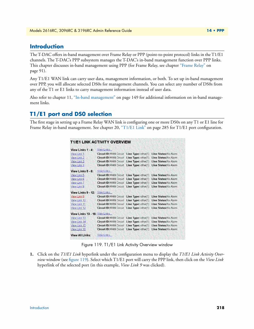
Models 2616RC, 3096RC & 3196RC Admin Reference Guide 14 • PPP
IntroductionThe T-DAC offers in-band management over Frame Relay or PPP (point-to-point protocol) links in the T1/E1 channels. The T-DAC’s PPP subsystem manages the T-DAC’s in-band management function over PPP links. This chapter discusses in-band management using PPP (for Frame Relay, see chapter “Frame Relay” on page 91).
Any T1/E1 WAN link can carry user data, management information, or both. To set up in-band management over PPP, you will allocate selected DS0s for management channels. You can select any number of DS0s from any of the T1 or E1 links to carry management information instead of user data.
Also refer to chapter 11, “In-band management” on page 149 for additional information on in-band manage-ment links.
T1/E1 port and DS0 selectionThe first stage in setting up a Frame Relay WAN link is configuring one or more DS0s on any T1 or E1 line for Frame Relay in-band management. See chapter 20, “T1/E1 Link” on page 285 for T1/E1 port configuration.
Figure 119. T1/E1 Link Activity Overview window
1. Click on the T1/E1 Link hyperlink under the configuration menu to display the T1/E1 Link Activity Over-view window (see figure 119). Select which T1/E1 port will carry the PPP link, then click on the View Link hyperlink of the selected port (in this example, View Link 9 was clicked).
Introduction 218
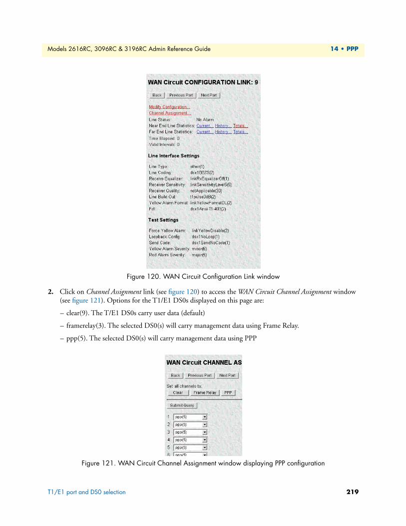
Models 2616RC, 3096RC & 3196RC Admin Reference Guide 14 • PPP
Figure 120. WAN Circuit Configuration Link window
2. Click on Channel Assignment link (see figure 120) to access the WAN Circuit Channel Assignment window (see figure 121). Options for the T1/E1 DS0s displayed on this page are:
– clear(9). The T/E1 DS0s carry user data (default)
– framerelay(3). The selected DS0(s) will carry management data using Frame Relay.
– ppp(5). The selected DS0(s) will carry management data using PPP
Figure 121. WAN Circuit Channel Assignment window displaying PPP configuration
T1/E1 port and DS0 selection 219
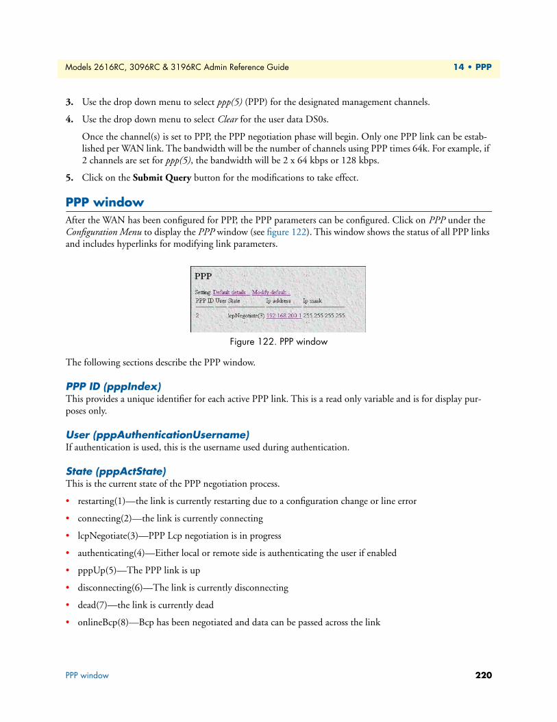
Models 2616RC, 3096RC & 3196RC Admin Reference Guide 14 • PPP
3. Use the drop down menu to select ppp(5) (PPP) for the designated management channels.
4. Use the drop down menu to select Clear for the user data DS0s.
Once the channel(s) is set to PPP, the PPP negotiation phase will begin. Only one PPP link can be estab-lished per WAN link. The bandwidth will be the number of channels using PPP times 64k. For example, if 2 channels are set for ppp(5), the bandwidth will be 2 x 64 kbps or 128 kbps.
5. Click on the Submit Query button for the modifications to take effect.
PPP windowAfter the WAN has been configured for PPP, the PPP parameters can be configured. Click on PPP under the Configuration Menu to display the PPP window (see figure 122). This window shows the status of all PPP links and includes hyperlinks for modifying link parameters.
Figure 122. PPP window
The following sections describe the PPP window.
PPP ID (pppIndex)This provides a unique identifier for each active PPP link. This is a read only variable and is for display pur-poses only.
User (pppAuthenticationUsername)If authentication is used, this is the username used during authentication.
State (pppActState)This is the current state of the PPP negotiation process.
• restarting(1)—the link is currently restarting due to a configuration change or line error
• connecting(2)—the link is currently connecting
• lcpNegotiate(3)—PPP Lcp negotiation is in progress
• authenticating(4)—Either local or remote side is authenticating the user if enabled
• pppUp(5)—The PPP link is up
• disconnecting(6)—The link is currently disconnecting
• dead(7)—the link is currently dead
• onlineBcp(8)—Bcp has been negotiated and data can be passed across the link
PPP window 220
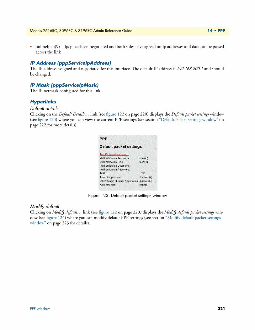
Models 2616RC, 3096RC & 3196RC Admin Reference Guide 14 • PPP
• onlineIpcp(9)—Ipcp has been negotiated and both sides have agreed on Ip addresses and data can be passed across the link
IP Address (pppServiceIpAddress)The IP address assigned and negotiated for this interface. The default IP address is 192.168.200.1 and should be changed.
IP Mask (pppServiceIpMask)The IP netmask configured for this link.
HyperlinksDefault detailsClicking on the Default Details… link (see figure 122 on page 220) displays the Default packet settings window (see figure 123) where you can view the current PPP settings (see section “Default packet settings window” on page 222 for more details).
Figure 123. Default packet settings window
Modify defaultClicking on Modify default… link (see figure 122 on page 220) displays the Modify default packet settings win-dow (see figure 124) where you can modify default PPP settings (see section “Modify default packet settings window” on page 223 for details).
PPP window 221
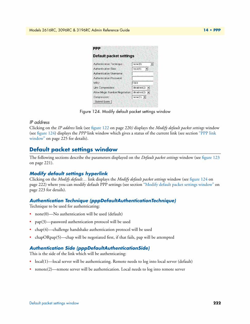
Models 2616RC, 3096RC & 3196RC Admin Reference Guide 14 • PPP
Figure 124. Modify default packet settings window
IP addressClicking on the IP address link (see figure 122 on page 220) displays the Modify default packet settings window (see figure 124) displays the PPP link window which gives a status of the current link (see section “PPP link window” on page 225 for details).
Default packet settings windowThe following sections describe the parameters displayed on the Default packet settings window (see figure 123 on page 221).
Modify default settings hyperlinkClicking on the Modify default… link displays the Modify default packet settings window (see figure 124 on page 222) where you can modify default PPP settings (see section “Modify default packet settings window” on page 223 for details).
Authentication Technique (pppDefaultAuthenticationTechnique)Technique to be used for authenticating:
• none(0)—No authentication will be used (default)
• pap(3)—password authentication protocol will be used
• chap(4)—challenge handshake authentication protocol will be used
• chapORpap(5)—chap will be negotiated first, if that fails, pap will be attempted
Authentication Side (pppDefaultAuthenticationSide)This is the side of the link which will be authenticating:
• local(1)—local server will be authenticating. Remote needs to log into local server (default)
• remote(2)—remote server will be authentication. Local needs to log into remote server
Default packet settings window 222
Models 2616RC, 3096RC & 3196RC Admin Reference Guide 14 • PPP
Authentication Username (pppDefaultAuthenticationUsername)This is the username that will be sent to the remote side if the remote machine is authenticating. If the local server is authenticating, the username that the remote sends will be compared to this username. Maximum size is 40 characters.
Authentication Password (pppDefaultAuthenticationPassword)This is the password that will be sent to the remote side if the remote machine is authenticating. If the local server is authenticating, the password that the remote sends will be compared to this username. Maximum size is 40 characters.
MRU (pppDefaultInitialMRU)This is the initial maximum received unit that will be negotiated for the link. This could possibly be changed during PPP negotiations. Default is 1500.
Link Compression (pppDefaultLinkCompression)This object enables the PPP link layer address and protocol field compression. When enabled the PPP negotia-tions will DESIRE link compression but may disable the compression due the other end of the link not accept-ing link compression. When disabled the PPP negotiations will FORCE no compression on the PPP link.
• enabled(1)—enable link compression
• disabled(2)—disable link compression (default)
Allow Magic Number Negotiation(pppDefaultMagicNumber)Determines if magic number negotiation should be done
• enabled(1)—enable magic number negotiation
• disabled(2)—disable magic number negotiation (default)
Compression (pppDefaultIpCompression)If none(1) then the local node will not attempt to negotiate any IP compression option. Otherwise, the local node will attempt to negotiate compression mode indicated by the enumerated value. Changing this object will have effect when the link is next restarted.
• none(1)—do not negotiate IP compression negotiated (default)
• vj-tcp(2)—van-jacobson TCP/IP header compression will be negotiated per RFC 1332.
Modify default packet settings windowThe Modify default packet settings window (see figure 124 on page 222) is where you can modify the default PPP settings that each PPP link will take when first initialized. Settings for individual links can be changed as described in section “Modify Link Configuration window” on page 231.
Note When you are finished modifying the default settings, click the Sub-mit Query button to apply the changes.
Modify default packet settings window 223
Models 2616RC, 3096RC & 3196RC Admin Reference Guide 14 • PPP
Authentication Technique (pppDefaultAuthenticationTechnique)Technique to be used for authenticating:
• none(0)—No authentication will be used (default)
• pap(3)—password authentication protocol will be used
• chap(4)—challenge handshake authentication protocol will be used
• chapORpap(5)—chap will be negotiated first, if that fails, pap will be attempted
Authentication Side (pppDefaultAuthenticationSide)This is the side of the link which will be authenticating:
• local(1)—local server will be authenticating. Remote needs to log into local server (default)
• remote(2)—remote server will be authentication. Local needs to log into remote server
Authentication Username (pppDefaultAuthenticationUsername)This is the username that will be sent to the remote side if the remote machine is authenticating. If the local server is authenticating, the username that the remote sends will be compared to this username. Maximum size is 40 characters.
Authentication Password (pppDefaultAuthenticationPassword)This is the password that will be sent to the remote side if the remote machine is authenticating. If the local server is authenticating, the password that the remote sends will be compared to this username. Maximum size is 40 characters.
MRU (pppDefaultInitialMRU)This is the initial maximum received unit that will be negotiated for the link. This could possibly be changed during PPP negotiations. Default is 1500.
Link Compression (pppDefaultLinkCompression)This object enables the PPP link layer address and protocol field compression. When enabled the PPP negotia-tions will DESIRE link compression but may disable the compression due the other end of the link not accept-ing link compression. When disabled the PPP negotiations will FORCE no compression on the PPP link.
• enabled(1)—enable link compression
• disabled(2)—disable link compression (default)
Allow Magic Number Negotiation(pppDefaultMagicNumber)Determines if magic number negotiation should be done
• enabled(1)—enable magic number negotiation
• disabled(2)—disable magic number negotiation (default)
Modify default packet settings window 224
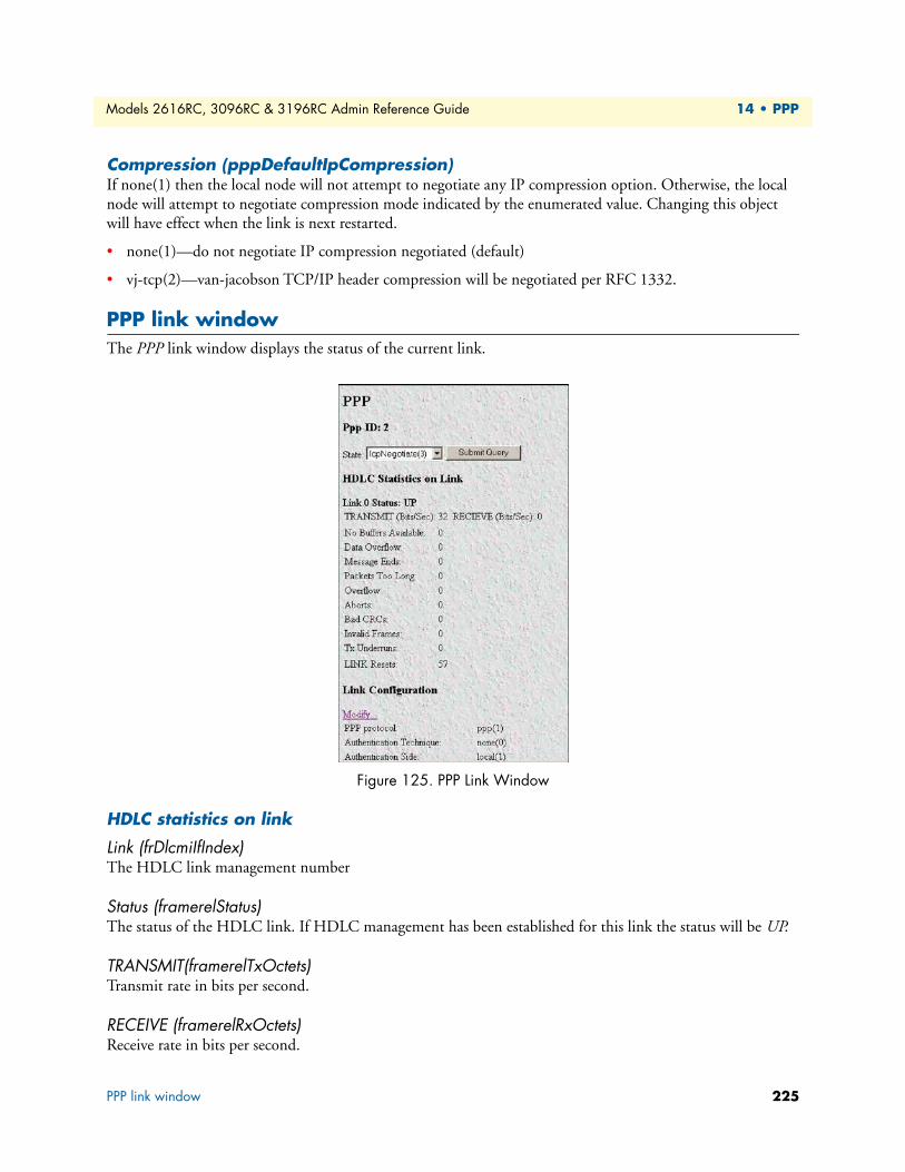
Models 2616RC, 3096RC & 3196RC Admin Reference Guide 14 • PPP
Compression (pppDefaultIpCompression)If none(1) then the local node will not attempt to negotiate any IP compression option. Otherwise, the local node will attempt to negotiate compression mode indicated by the enumerated value. Changing this object will have effect when the link is next restarted.
• none(1)—do not negotiate IP compression negotiated (default)
• vj-tcp(2)—van-jacobson TCP/IP header compression will be negotiated per RFC 1332.
PPP link windowThe PPP link window displays the status of the current link.
Figure 125. PPP Link Window
HDLC statistics on link
Link (frDlcmiIfIndex)The HDLC link management number
Status (framerelStatus)The status of the HDLC link. If HDLC management has been established for this link the status will be UP.
TRANSMIT(framerelTxOctets)Transmit rate in bits per second.
RECEIVE (framerelRxOctets)Receive rate in bits per second.
PPP link window 225
Models 2616RC, 3096RC & 3196RC Admin Reference Guide 14 • PPP
No Buffers Available (framerelRxNoBufferAvailable)The number of packets received when no receive buffers were available.
Data Overflow (framerelRxDataOverflow)The number of packets received with overflow indicated by the hardware.
Message Ends (framerelRxMessageEnds)The number of packets received with message-correct endings. This value increases each time a valid packet is received.
Packets Too Long (framerelRxPacketTooLong)The number of packets received that were too long.
Overflow (framerelRxOverflow)The number of packets received with overflow indicated by software.
Aborts (framerelRxAbort)The number of packets received that were aborted.
Bad CRCs (framerelRxBadCrc)The number of packets received with bad CRC values.
Invalid Frames (framerelRxInvalidFrame)The number of packets received with invalid frames.
Tx Underruns (framerelTxUnderrun)The number of times the transmit buffer was not replenished in time to be sent out on the line.
LINK Resets (framerelResets)Number of times the link was reset.
Link Configuration
PPP Protocol (pppDesiredFunction)This is the actual desired kind of PPP protocol
• ppp-ipcp(1) —point-to-point protocol
• ppp-bcp(2)—bridge control protocol
Authentication Technique (pppAuthenticationTechnique)The login technique to use for authentication.
• none(0)—No authentication will be used
• pap(3)—password authentication protocol will be used
• chap(4)—challenge handshake authentication protocol will be used
• chapORpap(5)—chap will be negotiated first, if that fails, pap will be attempted
PPP link window 226
Models 2616RC, 3096RC & 3196RC Admin Reference Guide 14 • PPP
Authentication Side (pppAuthenticationSide)This is the side of the link which will be authenticating
• local(1)—local server will be authenticating. Remote needs to log into local server.
• remote(2)—remote server will be authentication. Local needs to log into remote server.
Authentication username (pppAuthenticationUsername)This is the username that will be sent to the remote side if the remote machine is authenticating. If the local server is authenticating, the username that the remote sends will be compared to this username. Maximum size is 40 characters.
Authentication password (pppAuthenticationPassword)This is the password that will be sent to the remote side if the remote machine is authenticating. If the local server is authenticating, the password that the remote sends will be compared to this username. Maximum size is 40 characters.
MRU (pppInitialMRU)Initial setting for Maximum Receive Unit (MRU), used for the PPP negotiation
IP Address (pppServiceIpAddress)This object defines the IP address which will be used for the PPP link
IP Mask (pppServiceIpMask)This object defines the IP mask, which will be used for the PPP link
IP Compression (pppIpCompression)This object defines whether Van Jacobson header compression is used or not.
IP Force Next Hop (pppForceNextHop)This object defines the IP address of the interface, which should be the next hop for the packets—fast routing
Link Compression (pppLinkCompression)This object enables the PPP link layer address and protocol field compression. When enabled the PPP negotia-tions will desire link compression but may disable the compression due the other end of the link not accepting link compression. When disabled the PPP negotiations will force no compression on the PPP link.
• enabled(1)—enable link compression
• disabled(2)—disable link compression
Allow Magic Number Negotiation (pppMagicNumber)Determines if magic number negotiation should be done
• enabled(1)—enable magic number negotiation
• disabled(2)—disable magic number negotiation
PPP link window 227

Models 2616RC, 3096RC & 3196RC Admin Reference Guide 14 • PPP
PPP Statistics
Bad Address (pppStatBadAddresses)The number of packets received with an incorrect address field.
Bad Controls (pppStatBadControls)The number of packets received on this link with an incorrect control field.
Packets Too Long (pppStatPacketTooLongs)The number of packets received that have been discarded because their length exceeded the maximum receive unit (MRU).
LCP StatisticsThis portion of the Statistics window shows LCP statistics of the PPP link selected.
Local MRU (pppStatLocalMRU)The current value of the MRU for the local PPP entity. This value is the MRU that the remote entity is using when sending packets to the local PPP entity. This setting becomes active when the link is in the up—able to pass packets—operational state
Remote MRU (pppStatRemoteMRU)The current value of the MRU for the remote PPP entity. This value is the MRU that the local entity is using when sending packets to the remote PPP entity. This setting becomes active when the link is in the up—able to pass packets operational state.
LCP Authentication (pppStatLcpAuth)Authentication type used by the dial-in user. The following options are available:
• none(1)
• pap(2)
• chap(3)
• MSChap(4)—not currently implemented
Local ACC Map (pppStatLocalToPeerACCMap)The current value of the ACC Map used for sending packets from the local unit to the remote unit. The local unit sends this character map to the remote peer modem to ensure that the data being transferred is interpreted correctly. This setting becomes active when the link is in the up—able to pass packets operational state.
Remote ACC Map (pppStatPeerToLocalACCMap)The current value of the ACC Map used by the remote peer unit when transmitting packets to the local unit. The local unit sends this character map to the remote peer unit to ensure that the data being transferred is interpreted correctly. The remote peer unit combines its ACC Map with the map received from the local unit. This setting becomes active when the link is in the up—able to pass packets—operational.
PPP link window 228
Models 2616RC, 3096RC & 3196RC Admin Reference Guide 14 • PPP
Local PPP Protocol Comprsn (pppStatLocalToRemoteProtComp)Indicates whether the local PPP entity will use protocol compression when transmitting packets to the remote PPP entity. This setting becomes active when the link is in the up—able to pass packets—operational state.
These are the available options:
• disabled(0)—PPP compression is disabled
• enabled(1)—PPP compression is enabled
Remote PPP Protocol Comprsn (diStatRemoteToLocalProtComp)Indicates whether the remote PPP entity will use protocol compression when transmitting packets to the local PPP entity. This setting becomes active when the link is in the up—able to pass packets—operational state These are the available options:
• disabled(0)—PPP compression is disabled
• enabled(1)—PPP compression is enabled
Local AC Comprsn (pppStatLocalToRemoteACComp)Indicates whether the local PPP entity will use address and control compression (ACC) when transmitting packets to the remote PPP entity. This setting becomes active when the link is in the up—able to pass packets —operational state.
These are the available options:
• disabled(0)—ACC is disabled
• enabled(1)—ACC is enabled
Remote AC Comprsn (pppStatRemoteToLocalACComp)Indicates whether the remote PPP entity will use address and control compression (ACC) when transmitting packets to the local PPP entity. This setting becomes active when the link is in the up—able to pass packets— operational state.
These are the available options:
• disabled(0)—ACC is disabled
• enabled(1)—ACC is enabled
Local Frame Check Seq. Size (pppStatTransmitFcsSize)The size of the Frame Check Sequence (FCS) in bits that the local node will generate when sending packets to the remote node. This setting becomes active when the link is in the up—able to pass packets—operational State.
The values are from 0 to 128.
Remote Frame Check Seq. Size (pppStatReceiveFcsSize)The size (in bits) of the frame check sequence (FCS) that the remote node will generate when sending packets to the local node. This setting becomes active when the link is in the up—able to pass packets—operational state. The values are from 0 to 128.
PPP link window 229
Models 2616RC, 3096RC & 3196RC Admin Reference Guide 14 • PPP
IP Statistics
Operational Status (pppIpOperStatus)The current operational state of the interface. These are the available options:
• up(1)—able to pass packets
• down(2)—unable to pass packets
• testing(3)—in test mode and unable to pass packets
Local VJ Protocol Comprsn (pppIpLocalToRemoteCompProt)The IP compression protocol that the local IP entity uses when sending packets to the remote IP entity. The available settings are:
• none(1)—no compression
• vjTCP(2)—compression is enabled
Remote VJ Protocol Comprsn (pppIpRemoteToLocalCompProt)The IP compression protocol that the remote IP entity uses when sending packets to the local IP entity. The available settings are:
• none(1)—no compression
• vjTCP(2)—enabled
Remote Max Slot ID (pppIpRemoteMaxSlotId)The Max-Slot-Id access server parameter that the remote node has announced and that is in use on the link. If vjTCP header compression is not in use on the link, the value of this object will be 0. The range is from 0 to 255.
Local Max Slot ID (pppIpLocalMaxSlotId)The Max-Slot-Id access server parameter that the local node has announced and that is in use on the link. If vjTCP header compression is not in use on the link, the value of this object will be 0. The range is from 0 to 255.
Data Statistics
Octets Sent (pppActSentOctets)The number of octets (bytes) sent during this session.
Octets Received (pppActReceivedOctets)The number of octets (bytes) received during this session.
Packets Sent (pppActSentDataFrames)The number of packets sent during this session. Version 6 nomenclature for a packet is Ipv6 header plus payload.
Packets Received (pppActReceivedDataFrames)The number of packets received during this session. Version 6 nomenclature for a packet is Ipv6 header plus payload.
PPP link window 230

Models 2616RC, 3096RC & 3196RC Admin Reference Guide 14 • PPP
Modify Link Configuration windowClicking on the Modify… link in the PPP link window (see figure 125 on page 225) displays the Modify Link Configuration window (see figure 126) where you can modify individual link settings.
Figure 126. Link configuration
Note When you are finished modifying the link configuration, click the Submit Query button to apply the changes.
PPP Protocol (pppDesiredFunction)This is the actual desired kind of PPP protocol
• ppp(1) —point-to-point protocol
• ppp-bcp(2)—bridge control protocol
Authentication Technique (pppAuthenticationTechnique)The login technique to use for authentication.
• none(0)—No authentication will be used
• pap(3)—password authentication protocol will be used
• chap(4)—challenge handshake authentication protocol will be used
• chapORpap(5)—chap will be negotiated first, if that fails, pap will be attempted
Modify Link Configuration window 231
Models 2616RC, 3096RC & 3196RC Admin Reference Guide 14 • PPP
Authentication Side (pppAuthenticationSide)This is the side of the link which will be authenticating
• local(1)—local server will be authenticating. Remote needs to log into local server.
• remote(2)—remote server will be authentication. Local needs to log into remote server.
Authentication Username (pppAuthenticationUsername)This is the username that will be sent to the remote side if the remote machine is authenticating. If the local server is authenticating, the username that the remote sends will be compared to this username. Maximum size is 40 characters.
Authentication Password (pppAuthenticationPassword)This is the password that will be sent to the remote side if the remote machine is authenticating. If the local server is authenticating, the password that the remote sends will be compared to this username. Maximum size is 40 characters.
Security level (pppAccessLevel)The security level given to this call.
• passthru(1)—allows no access in the configuration screens
• monitor(2)—allows read-only access to the configuration screens
• change(3)—allows full read and write access to the configuration screens
MRU (pppInitialMRU)Initial setting for Maximum Receive Unit (MRU), used for the PPP negotiation
IP Address (pppServiceIpAddress)This object defines the IP address which will be used for the PPP link
IP Mask (pppServiceIpMask)This object defines the IP mask, which will be used for the PPP link
IP Compression (pppIpCompression)This object defines the IP compression for the link
IP Force Next Hop (pppForceNextHop)This object defines the IP address of the interface, which should be the next hop for the packets—fast routing
Link Compression (pppLinkCompression)This object enables the PPP link layer address and protocol field compression. When enabled the PPP negotia-tions will desire link compression but may disable the compression due the other end of the link not accepting link compression. When disabled the PPP negotiations will force no compression on the PPP link.
• enabled(1)—enable link compression
• disabled(2)—disable link compression
Modify Link Configuration window 232

Models 2616RC, 3096RC & 3196RC Admin Reference Guide 14 • PPP
Allow Magic Number Negotiation (pppMagicNumber)Determines if magic number negotiation should be done
• enabled(1)—enable magic number negotiation
• disabled(2)—disable magic number negotiation
Modify Link Configuration window 233

Chapter 15 RIP Version 2
Chapter contentsIntroduction ........................................................................................................................................................235RIP Version 2 Overview window.........................................................................................................................235
RIP Summary Statistics .................................................................................................................................235Defined RIP Addresses ..................................................................................................................................236Define a New RIP Address ............................................................................................................................236
RIP Version 2 Statistics .......................................................................................................................................237Subnet IP Address (rip2IfStatAddress) ..........................................................................................................237Bad Packets (rip2IfStatRcvBadPackets) .........................................................................................................238Bad Routes (rip2IfStatRcvBadRoutes) ..........................................................................................................238Sent Updates (rip2IfStatSentUpdates) ...........................................................................................................238Status (rip2IfStatStatus) ................................................................................................................................238
RIP Version 2 (Configuration) window...............................................................................................................238Address (rip2IfConfAddress) .........................................................................................................................239Domain (rip2IfConfDomain) .......................................................................................................................239Authentication Type (rip2IfConfAuthType) .................................................................................................239Authentication Key (rip2IfConfAuthKey) .....................................................................................................239Metric (rip2IfConfDefaultMetric) ................................................................................................................239Status (rip2IfConfStatus) ..............................................................................................................................239
234

Models 2616RC, 3096RC & 3196RC Admin Reference Guide 15 • RIP Version 2
IntroductionThe T-DAC provides support for Routing Information Protocol (RIP) Version 2. The T-DAC RIP version 2 subsystem provides management information in the form of RIP Version 2 addresses, parameters, and statis-tics. Managing the RIP version 2 subsystem involves defining RIP Version 2 addresses and parameters, and monitoring RIP Version 2 parameters and statistics on TCP.
All object identifiers described in this chapter comply with those contained in RFC 1724: RIP Version 2 MIB Extension.
RIP Version 2 Overview windowThe RIP Version 2 Overview window (see figure 127) provides the means for you to manage the T-DAC’s RIP Version 2 subsystem. The window displays the current values of certain RIP Version 2 operating parameters and statistics, and provides the means for you to add IP addresses to the T-DAC’s RIP Version 2 table. The window contains the following main sections:
• The RIP Summary Statistics section
• The Defined RIP Addresses section
• The Define a New RIP Address section
Figure 127. RIP Version 2 Overview window
To display the RIP Version 2 Overview window, on the T-DAC configuration menu pane, click the RIP Version 2 link.
The following sections describe the contents of the tables displayed on the RIP Version 2 main window.
RIP Summary Statistics• Statistics hyperlink—Clicking on the Detailed Statistics link displays the RIP Version 2 Statistics window
(see “RIP Version 2 Statistics” on page 237). For each subnet IP address in the T-DAC’s RIP Version 2 table, the RIP Version 2 Statistics window displays the RIP route status and statistical counts for Bad Pack-ets, Bad Routes, and Sent Updates.
• Route Changes Made (rip2GlobalRouteChanges)—The number of route changes made to the IP Route Database by RIP. This does not include the refresh of a route’s age.
• Responses Sent (rip2GlobalQueries)—The number of responses sent to RIP queries from other systems.
Introduction 235

Models 2616RC, 3096RC & 3196RC Admin Reference Guide 15 • RIP Version 2
Defined RIP Addresses• Address (xxx.xxx.xxx.xxx) (rip2IfConfAddress)—Each IP Address in the table defines a single routing
domain in a single subnet for the T-DAC—to use when making RIP routing decisions.
Note Each IP Address displayed in the RIP Version 2 table also functions as a hyperlink to the RIP Version 2 Parameters window (see section “RIP Version 2 (Configuration) window” on page 238). You can use the RIP Version 2 Parameters window to view and modify the param-eters for a single address.
Initially, because the T-DAC RIP Version 2 table is empty, the RIP Version 2 main window will not display any address hyperlinks. You can use the Adding a RIP Address table to add one more IP addresses to the T-DAC RIP Version 2 table (see Adding a RIP address). Once you have defined a RIP version 2 address, that address will appear in the table. To view the configurable parameters for an address, click on the Address hyperlink under the Address column to display the RIP Version 2 Parameters window (see “RIP Version 2 Statistics” on page 237).
• Send (rip2IfConfSend)—Send is what the router sends on this interface. ripVersion 1 implies sending RIP updates compliant with RFC 1058 rip1Compatible(3), and ripVersion2(4). The following options are available:
- doNotSend(1)
- ripVersion1(2)
- rip1Compatible (3)—rip1Compatible implies broadcasting RIP-2 updates using RFC 1058 route sub-sumption rules
- ripVersion2 (4)—ripVersion2 implies multicasting RIP-2 updates
• Receive (rip2IfConfReceive)—This indicates which version of RIP updates are to be accepted.
- rip1 (1)
- rip2 (2)
- rip1OrRip2 (3)
- doNotRecieve (4)
Note Options rip2 and rip1OrRip2 imply reception of multicast packets.
Define a New RIP Address To add a RIP address to the T-DAC’s RIP Version 2 table, do the following:
1. Enter the IP network address of the interface on the T-DAC that you want to enable RIP. This will be the LAN IP address, in other words, the IP address of the T-DAC. This is not the IP address of the device you want to direct RIP packets to.
2. Enter the protocol version to be used for sending RIP packets. The following choices are available:
– doNotSend (1)
– ripVersion1 (2)—ripVersion 1 implies sending RIP updates compliant with RFC 1058
RIP Version 2 Overview window 236

Models 2616RC, 3096RC & 3196RC Admin Reference Guide 15 • RIP Version 2
– rip1Compatible (3)—rip1Compatible implies broadcasting RIP-2 updates using RFC 1058 route sub-sumption rules
– ripVersion2 (4)—ripVersion2 implies multicasting RIP-2 updates
3. Enter the protocol version to be used for receiving RIP packets. The following choices are available:
– rip1 (1)—ripVersion 1 implies sending RIP updates compliant with RFC 1058
– rip2(2)—rip1Compatible implies broadcasting RIP-2 updates using RFC 1058 route subsumption rules
– rip1OrRip2(3)
– doNotReceive(4)
Note Options rip2 and rip1OrRip2 imply reception of multicast packets.
4. Click on Submit Query.
Note To delete the RIP address, click on the IP Address under the col-umn named Address. Select Status to be invalid(2) and click on Define.
To view and modify additional configurable parameters for the RIP address, click on the Address hyperlink to display the RIP Version Configuration window.
RIP Version 2 StatisticsFor each subnet IP address defined in the T-DAC’s RIP Version 2 table, the RIP Version 2 Statistics window (see figure 129) displays the RIP route status and the following statistical counts:
• Bad Packets
• Bad Routes
• Sent Updates
To display the RIP Version 2 Statistics window, on the RIP Version 2 main window, click the Statistics… link.
Figure 128. RIP Version 2 Statistics window
The following sections describe the information displayed on the RIP Version 2 Statistics window.
Subnet IP Address (rip2IfStatAddress)The IP Address of this system on the indicated subnet. For unnumbered interfaces, the value 0.0.0.N, where the least significant 24 bits (N) is the ifIndex for the IP Interface in network byte order.
RIP Version 2 Statistics 237
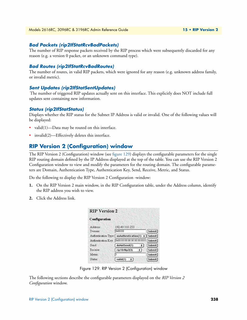
Models 2616RC, 3096RC & 3196RC Admin Reference Guide 15 • RIP Version 2
Bad Packets (rip2IfStatRcvBadPackets)The number of RIP response packets received by the RIP process which were subsequently discarded for any reason (e.g. a version 0 packet, or an unknown command type).
Bad Routes (rip2IfStatRcvBadRoutes)The number of routes, in valid RIP packets, which were ignored for any reason (e.g. unknown address family, or invalid metric).
Sent Updates (rip2IfStatSentUpdates) The number of triggered RIP updates actually sent on this interface. This explicitly does NOT include full updates sent containing new information.
Status (rip2IfStatStatus)Displays whether the RIP status for the Subnet IP Address is valid or invalid. One of the following values will be displayed:
• valid(1)—Data may be routed on this interface.
• invalid(2)—Effectively deletes this interface.
RIP Version 2 (Configuration) windowThe RIP Version 2 (Configuration) window (see figure 129) displays the configurable parameters for the single RIP routing domain defined by the IP Address displayed at the top of the table. You can use the RIP Version 2 Configuration window to view and modify the parameters for the routing domain. The configurable parame-ters are Domain, Authentication Type, Authentication Key, Send, Receive, Metric, and Status.
Do the following to display the RIP Version 2 Configuration -window:
1. On the RIP Version 2 main window, in the RIP Configuration table, under the Address column, identify the RIP address you wish to view.
2. Click the Address link.
Figure 129. RIP Version 2 (Configuration) window
The following sections describe the configurable parameters displayed on the RIP Version 2 Configuration window.
RIP Version 2 (Configuration) window 238
Models 2616RC, 3096RC & 3196RC Admin Reference Guide 15 • RIP Version 2
Address (rip2IfConfAddress) The IP Address of this system on the indicated subnet. For unnumbered interfaces, the value 0.0.0.N, where the least significant 24 bits (N) is the ifIndex for the IP Interface in network byte order.
Domain (rip2IfConfDomain) Value inserted into the Routing Domain field of all RIP packets sent on this interface.
Authentication Type (rip2IfConfAuthType) The type of Authentication used on this interface.
• noAuthentication (1)
• simplePassword (2)
Authentication Key (rip2IfConfAuthKey)This value is used as the Authentication Key whenever Authentication Type (rip2IfConfAuthType) has a value other than noAuthentication(1). A modification of Authentication Type does not change the value of Authen-tication Key. If the Authentication Key string is shorter than 16 octets, it will be left justified, then padded to 16 octets with nulls (0x00) on the right.
Reading this object always results in an octet string of length zero. Authentication may not be bypassed by reading the MIB object.
Metric (rip2IfConfDefaultMetric)This variable indicates the metric that is to be used for the default route entry in RIP updates originated on this interface. A value of zero indicates that no default route should be originated; in this case, a default route via another router may be propagated.
Status (rip2IfConfStatus)Writing invalid has the effect of deleting this interface.
• valid (1)
• invalid (2)
RIP Version 2 (Configuration) window 239

Chapter 16 SNMP
Chapter contentsIntroduction ........................................................................................................................................................241SNMP Overview window....................................................................................................................................241
SNMP Parameters (snmpEnableAuthenTraps) .............................................................................................242SNMP Statistics ............................................................................................................................................242
Received Statistics ...................................................................................................................................242Packets (snmpInPkts) ........................................................................................................................ 242Bad Version (snmpInBadVersions).................................................................................................... 242Bad Community Names (snmpInBadCommunityNames) ................................................................ 242Bad Community Uses (snmpInBadCommunity Uses) ...................................................................... 242ASN ParseErrors (snmpInASNParseErrs) .......................................................................................... 242Error Status “Too Big” (snmpInTooBigs) ......................................................................................... 242No Such Names (snmpInNoSuchNames) ......................................................................................... 242Bad Values (snmpInBadValues)......................................................................................................... 243Error Status “Read Only” (snmpInReadOnlys) ................................................................................. 243Generated Errors (snmpInGenErrs)................................................................................................... 243Get/Get Next Variables (snmpInTotalReqVars) ................................................................................ 243Set Variables (snmpInTotalSetVars) .................................................................................................. 243Get Requests (snmpInGetRequests) .................................................................................................. 243Get Next Requests (snmpInGetNexts) .............................................................................................. 243Set Requests (snmpInSetRequests) .................................................................................................... 243Get Responses (snmpInGetResponses) .............................................................................................. 243Traps (snmpInTraps) ........................................................................................................................ 243
Transmitted Statistics ..............................................................................................................................243Out Packets (snmpOutPkts).............................................................................................................. 243
Error Status “Too Big” (snmpOutTooBigs) ...................................................................................... 243No Such Names (snmpOutNoSuchNames) ...................................................................................... 243Bad Values (snmpOutBadValues)...................................................................................................... 243Generated Errors (snmpOutGenErrs)................................................................................................ 243Get Requests (snmpOutGetRequests) ............................................................................................... 244Get Next Requests (snmpOutGetNexts) ........................................................................................... 244Set Requests (snmpOutSetRequests) ................................................................................................. 244Get Responses (snmpOutGetResponses) ........................................................................................... 244Traps (snmpOutTraps) ..................................................................................................................... 244
240
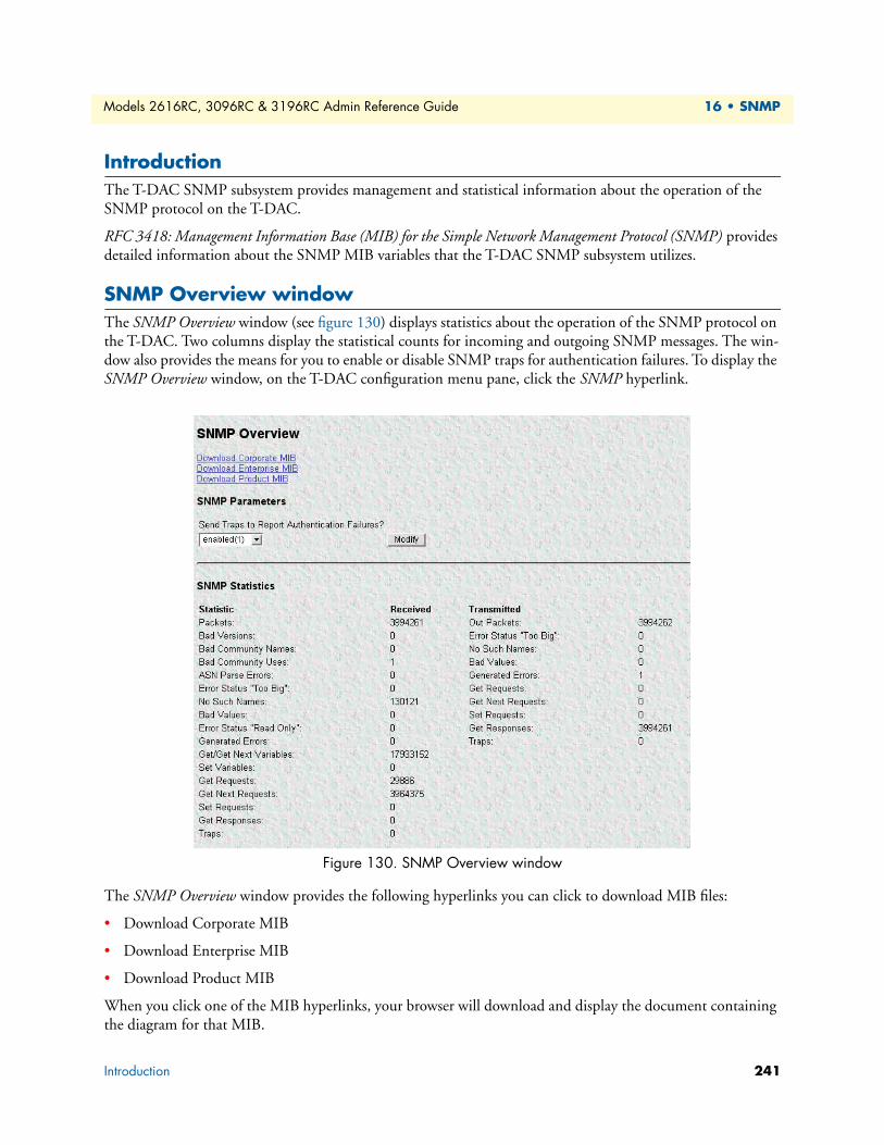
Models 2616RC, 3096RC & 3196RC Admin Reference Guide 16 • SNMP
IntroductionThe T-DAC SNMP subsystem provides management and statistical information about the operation of the SNMP protocol on the T-DAC.
RFC 3418: Management Information Base (MIB) for the Simple Network Management Protocol (SNMP) provides detailed information about the SNMP MIB variables that the T-DAC SNMP subsystem utilizes.
SNMP Overview windowThe SNMP Overview window (see figure 130) displays statistics about the operation of the SNMP protocol on the T-DAC. Two columns display the statistical counts for incoming and outgoing SNMP messages. The win-dow also provides the means for you to enable or disable SNMP traps for authentication failures. To display the SNMP Overview window, on the T-DAC configuration menu pane, click the SNMP hyperlink.
Figure 130. SNMP Overview window
The SNMP Overview window provides the following hyperlinks you can click to download MIB files:
• Download Corporate MIB
• Download Enterprise MIB
• Download Product MIB
When you click one of the MIB hyperlinks, your browser will download and display the document containing the diagram for that MIB.
Introduction 241

Models 2616RC, 3096RC & 3196RC Admin Reference Guide 16 • SNMP
The following sections describe the statistical counts displayed in the In and Out columns on the SNMP win-dow, as well as the configurable parameter for Authentication Failure Traps.
SNMP Parameters (snmpEnableAuthenTraps)This value indicates whether the SNMP agent process is permitted to generate authentication-failure traps. The variable is global. This means that by being disabled, all authentication-failure traps are disabled.
The two options for this variable are:
• enabled(1)
• disabled(2)
Once you have modified the value of Authentication Failure Traps you must click the Modify button to save your settings into volatile DRAM. Once you click the button, the T-DAC will implement the changes immediately.
Note To save your changes permanently, (i.e. through a T-DAC power cycle) you must visit the T-DAC HOME page, and click the Save Current Configuration button. When you click the Save Current Configuration button, the T-DAC will copy the configuration cur-rently stored in volatile DRAM into non-volatile Flash memory for permanent storage.
SNMP StatisticsThis section describes the statistical counts displayed in the statistics columns on the SNMP window.
Received StatisticsPackets (snmpInPkts). The total number of Messages delivered to the SNMP entity from the transport ser-vice. Typically this would be UDP since the SNMP engine sits on top of UDP
Bad Version (snmpInBadVersions). The total number of SNMP Messages that were delivered to the SNMP protocol entity and were for an unsupported SNMP version.
Bad Community Names (snmpInBadCommunityNames). The total number of SNMP Messages delivered to the SNMP protocol entity which used a SNMP community name not known to said entity.
Bad Community Uses (snmpInBadCommunity Uses). The total number of SNMP messages delivered to the SNMP protocol entity which represented an SNMP operation which was not allowed by the SNMP com-munity named in the message.
ASN ParseErrors (snmpInASNParseErrs). The total number of ASN.1 or BER errors encountered by the SNMP protocol entity when decoding received SNMP messages.
Error Status “Too Big” (snmpInTooBigs). The total number of SNMP PDUs that were delivered to the SNMP protocol entity and for which the value of the error-status field is tooBig.
No Such Names (snmpInNoSuchNames). The total number of SNMP PDUs that were delivered to the SNMP protocol entity and for which the value of the error-status field is noSuchName.
SNMP Overview window 242
Models 2616RC, 3096RC & 3196RC Admin Reference Guide 16 • SNMP
Bad Values (snmpInBadValues). The total number of SNMP PDUs that were delivered to the SNMP proto-col entity and for which the value of the error-status field is badValue.
Error Status “Read Only” (snmpInReadOnlys). The total number of valid SNMP PDUs that were deliv-ered to the SNMP protocol entity and for which the value of the error-status field is readOnly. It should be noted that it is a protocol error to generate an SNMP PDU which contains the readOnly value in the error-sta-tus field, as such this object is provided as a means of detecting incorrect implementations of the SNMP.
Generated Errors (snmpInGenErrs). The total number of SNMP PDUs that were delivered to the SNMP protocol entity and for which the value of the error-status field is genErr.
Get/Get Next Variables (snmpInTotalReqVars). The total number of MIB objects that have been retrieved successfully by the SNMP protocol entity as the result of receiving valid SNMP Get-Request and Get-Next PDUs.
Set Variables (snmpInTotalSetVars). The total number of MIB objects that have been altered successfully by the SNMP protocol entity as the result of receiving valid SNMP Set-Request PDUs.
Get Requests (snmpInGetRequests). The total number of SNMP Get-Request PDUs that have been accepted and processed by the SNMP protocol entity.
Get Next Requests (snmpInGetNexts). The total number of SNMP Get-Next PDUs that have been accepted and processed by the SNMP protocol entity.
Set Requests (snmpInSetRequests). The total number of SNMP Set-Request PDUs that have been accepted and processed by the SNMP protocol entity.
Get Responses (snmpInGetResponses). The total number of SNMP Get-Response PDUs that have been accepted and processed by the SNMP protocol entity.
Traps (snmpInTraps). The total number of SNMP Trap PDUs that have been accepted and processed by the SNMP protocol entity.
Transmitted StatisticsOut Packets (snmpOutPkts). The total number of SNMP messages that were passed from the SNMP proto-col entity to the transport service.
Error Status “Too Big” (snmpOutTooBigs). The total number of SNMP PDUs that were generated by the SNMP protocol entity and for which the value of the error-status field is tooBig.
No Such Names (snmpOutNoSuchNames). The total number of SNMP PDUs that were generated by the SNMP protocol entity and for which the value of the error-status is noSuchName.
Bad Values (snmpOutBadValues). The total number of SNMP PDUs that were generated by the SNMP pro-tocol entity and for which the value of the error-status field is badValue.
Generated Errors (snmpOutGenErrs). The total number of SNMP PDUs that were generated by the SNMP protocol entity and for which the value of the error-status field is genErr.
SNMP Overview window 243
Models 2616RC, 3096RC & 3196RC Admin Reference Guide 16 • SNMP
Get Requests (snmpOutGetRequests). The total number of SNMP Get-Request PDUs that have been gen-erated by the SNMP protocol entity.
Get Next Requests (snmpOutGetNexts). The total number of SNMP Get-Next PDUs that have been gener-ated by the SNMP protocol entity.
Set Requests (snmpOutSetRequests). The total number of SNMP Set-Request PDUs that have been gener-ated by the SNMP protocol entity.
Get Responses (snmpOutGetResponses). The total number of SNMP Get-Response PDUs that have been generated by the SNMP protocol entity.
Traps (snmpOutTraps). The total number of SNMP Trap PDUs that have been generated by the SNMP pro-tocol entity.
SNMP Overview window 244

Chapter 17 System
Chapter contentsIntroduction ........................................................................................................................................................248System Status Overview window .........................................................................................................................248
Hyperlinks ....................................................................................................................................................250General product information box ..................................................................................................................250Physical status table .......................................................................................................................................251Refresh Rate parameter .................................................................................................................................252System Status table ........................................................................................................................................252
Ethernet Status table............................................................................................................................................253T1/E1 Port Information table..............................................................................................................................254Port Information table.........................................................................................................................................255
G.SHDSL Port Information table ...........................................................................................................255iDSL Port Information table ...................................................................................................................256
System Status Details window .............................................................................................................................257CPU Statistics ...............................................................................................................................................258
% CPU Idle (boxIdletime) ......................................................................................................................258Time Slices Fully Utilized (boxCPUcritical) ............................................................................................258Time Slices 90% Utilized (boxCPUWarning) .........................................................................................258
Manufacturer Information ............................................................................................................................258Serial Number (boxManufactureDatecode) .............................................................................................258PCB Revision (boxManufacturePcbRevision) ..........................................................................................258General Information (boxManufactureGeneralInfo) ...............................................................................258CPLD Revision (boxCPLrevision) ...........................................................................................................258
Message Block Statistics ................................................................................................................................258Total (boxMsgBlksConfigured) ...............................................................................................................258
Free (boxMsgBlksFree) ............................................................................................................................258Total Time Waited (boxCountMsgBlkTaskWait) ...................................................................................259Total Times Unavailable (boxCountMsgBlkUnavailable) ........................................................................259
Operating System Heap Memory Statistics ...................................................................................................259Total Size (boxHeapSize) ........................................................................................................................259Free (boxHeapFreeSpace) ........................................................................................................................259Largest (boxHeapLargestSpace) ...............................................................................................................259
Enclosure System Temperature .....................................................................................................................259Internal Temperature (boxTemperature) .................................................................................................259Highest Temperature (boxMaxTemperature) ..........................................................................................259
System Parameters window..................................................................................................................................260Installation Parameters ..................................................................................................................................260
Country (installCountry) ........................................................................................................................260Total DRAM Detected (boxDetectedMemory) .......................................................................................260SystemID (sysObjectID) .........................................................................................................................260
245
Models 2616RC, 3096RC & 3196RC Admin Reference Guide 17 • System
Running Since Last Boot (sysUpTime) ...................................................................................................261System Manager (sysContact) ..................................................................................................................261Module Name (sysName) .......................................................................................................................261Physical Location (sysLocation) ...............................................................................................................261Background Image (boxBackgroundFlag) ................................................................................................261Monitor Privilege (boxMonitorPrivilege) ................................................................................................261Front Handle Reset (boxHandleResetEnable) .........................................................................................262Common Code Revision (boxCommonCodeRevision) ...........................................................................262
SNMP and HTTP Parameters ......................................................................................................................262Version (boxSnmpVersion) .....................................................................................................................262Superuser Password (boxSnmpMasterPassword) ......................................................................................262User Password (boxSnmpMonitorPassword) ...........................................................................................262
Modify Parameters window ..........................................................................................................................263Installation ....................................................................................................................................................263
System Manager (sysContact) ..................................................................................................................263Module Name (sysName) .......................................................................................................................263Physical Location (sysLocation) ...............................................................................................................263Web Settings (boxBackgroundFlag) ........................................................................................................263Monitor Privilege (boxMonitorPrivilege) ................................................................................................263Stats Refresh Rate (boxWebRefreshRate) ................................................................................................264Front Handle Reset .................................................................................................................................264
SNMP and HTTP ........................................................................................................................................264Version (boxSnmpVersion) .....................................................................................................................264Superuser Password (boxSnmpMasterPassword) ......................................................................................264Superuser Password Verification (boxSnmpVerifyMasterPassword) .........................................................264User Password (boxSnmpMonitorPassword) ...........................................................................................264User Password Verification (boxSnmpVerifyPassword) ...........................................................................265
System History Overview window.......................................................................................................................265T1/E1 port information table .......................................................................................................................266DSL Port Information table ..........................................................................................................................267
G.SHDSL port information table ............................................................................................................267iDSL port information table ....................................................................................................................267
(WAN) Circuit ID # History of Near End Performance window ........................................................................268Interval (dsx1IntervalNumber) ......................................................................................................................268Errored Seconds (dsx1intervaless) ..................................................................................................................268Severely Errored Seconds (dsx1IntervalSESs) ................................................................................................268Severely Errored Frame Seconds (dsx1IntervalSEFSs) ...................................................................................269Unavailable Seconds (dsx1IntervalUASs) ......................................................................................................269Controlled Slip Seconds (dsx1IntervalCSSs) .................................................................................................269Path Code Violations (dsx1IntervalPCVs) ....................................................................................................269Line Errored Seconds (dsx1IntervalLESs) ......................................................................................................269Bursty Errored Seconds (dsx1IntervalBESs) ..................................................................................................269Degraded Minutes (dsx1IntervalDMs) ..........................................................................................................269Line Code Violations (dsx1IntervalLCVs) .....................................................................................................269
246

Models 2616RC, 3096RC & 3196RC Admin Reference Guide 17 • System
History of Near End Performance: G.SHDSL or iDSL Port window ..................................................................270Interval (gshDSLIntervalNumber) ................................................................................................................270Errored Seconds (historyESgshDSL) .............................................................................................................270Severely Errored Seconds (historySESgshDSL) ..............................................................................................271Unavailable Seconds (historyUASgshDSL) ....................................................................................................271
247

Models 2616RC, 3096RC & 3196RC Admin Reference Guide 17 • System
IntroductionThe System Status Overview window provides system-level information about the Model 3096RC, 3196RC, or 2616RC T-DAC. The information includes physical status and system status (see figure 131), and Ethernet status, T1/E1 port information, and G.SHDSL (Model 3096RC) or iDSL (Model 3196RC) port information, as shown in figure 132 on page 249). Additional management pages contain system status details, system parameters, and system history.
Figure 131. System Status Overview window (part 1 of 2) (Model 3096RC shown)
System Status Overview windowThe System Status Overview window consists of the following sections:
• General product information—Displays the product name, software release identifier, and software release timestamp (see figure 131).
• Physical Status table—Displays current state of certain physical components of the T-DAC, including the front handle switch, rear handle switch, front READY LED (blue), and rear READY LED (blue).
• Refresh rate parameter—Determines how often the System Status Overview window is refreshed.
• System Status table—Displays the state of alarms, the internal temperature of the T-DAC’s—displayed in Celsius (C)/Fahrenheit (F), the current operational status of the two power supplies and the T-DAC’s sys-tem clock.
Introduction 248
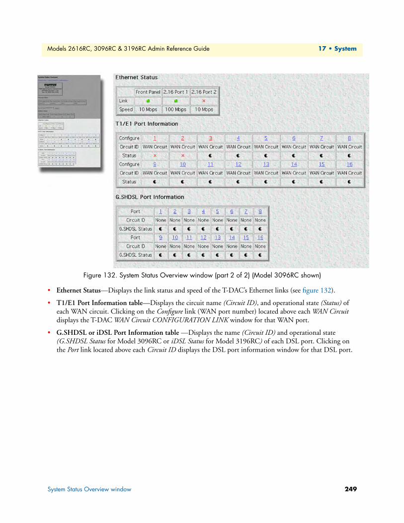
Models 2616RC, 3096RC & 3196RC Admin Reference Guide 17 • System
Figure 132. System Status Overview window (part 2 of 2) (Model 3096RC shown)
• Ethernet Status—Displays the link status and speed of the T-DAC’s Ethernet links (see figure 132).
• T1/E1 Port Information table—Displays the circuit name (Circuit ID), and operational state (Status) of each WAN circuit. Clicking on the Configure link (WAN port number) located above each WAN Circuit displays the T-DAC WAN Circuit CONFIGURATION LINK window for that WAN port.
• G.SHDSL or iDSL Port Information table —Displays the name (Circuit ID) and operational state (G.SHDSL Status for Model 3096RC or iDSL Status for Model 3196RC) of each DSL port. Clicking on the Port link located above each Circuit ID displays the DSL port information window for that DSL port.
System Status Overview window 249

Models 2616RC, 3096RC & 3196RC Admin Reference Guide 17 • System
HyperlinksAs shown in figure 133 on page 250, the System Status Overview window also provides links to the System Status Details window (see section “System Status Details window” on page 257), System Parameters window (see sec-tion “System Parameters window” on page 260) and the System History Overview window (see section “System History Overview window” on page 265).
Figure 133. System Status windows map
Figure 134. General product information box
General product information boxThe general product information box section of the System Status Overview window (see figure 134) provides the following information:
• Product name: Model 3096RC TDM Digital Access Concentrator or Model 3196RC TDM Digital Access Concentrator
• Software release identifier: The current software version running on the T-DAC. The identifier is in the form X.Y.Z(n) where:
– X denotes a major release involving an extensive system revision.
– Y indicates a revision within Release X adding one or more new features.
– Z denotes a revision within Release X.Y correcting problems that were found in the previous release.
– n (optional) is a lowercase alpha character. The value b for beta may indicate software made available to certain parties for before the official formal release to the general public, often for early access trials or field testing.
• Software release timestamp: The date and time the software version was created.
System Status Details
System Parameters
System Status Overview
System HistoryOverview
System Status Overview window 250

Models 2616RC, 3096RC & 3196RC Admin Reference Guide 17 • System
Figure 135. Physical status table and Refresh Rate menu
Physical status tableThe Physical Status section of the System Status Overview window (see figure 135) lists the possible conditions of the T-DAC components (see table 5).
Table 5. Physical states
Item Setting Description
Front handle switch Open The switch on at least one of the two front handles is open, indicating that the handle is unlocked. When both handles are unlocked, the blue READY LED status indicator on the T-DAC’s front panel will light, indicating that the T-DAC front blade is ready for removal. The T-DAC can then be removed from the CPCI chassis.
Closed Both front handle switches are closed, indicating that the handles are locked and the T-DAC cannot be removed from the cPCI chassis.
Rear handle switch Open The switch on at least one of the two rear handles is open, indicating that the handle is unlocked. When both handles are unlocked, the blue READY LED status indicator on the T-DAC’s rear blade will light, indicating that the rear blade is ready for removal. The rear blade can then be removed from the CPCI chassis.
Front READY LED (blue)
On The blue READY LED status indicator on the T-DAC’s front panel is lit, indicat-ing the switches on both front handles are open and the handles are unlocked, so the T-DAC is ready to be removed from the CPCI chassis.
Off The blue READY LED status indicator on the T-DAC’s front panel is not lit, indi-cating that the switches on at least one of the front handles are closed and the handle(s) are unlocked: the T-DAC is not ready for removal, and therefore cannot be removed from the CPCI chassis.
Rear READY LED (blue)
On The blue READY LED status indicator on the rear blade is lit, indicating that the switches on both rear handles are open and the handles are unlocked, so the rear blade is ready to be removed from the CPCI chassis.
Off The blue READY LED status indicator on the rear blade is not lit, indicating that the switches on at least one of the rear handles are closed and the han-dle(s) are unlocked: the rear blade is not ready for removal, and therefore cannot be removed from the CPCI chassis.
System Status Overview window 251
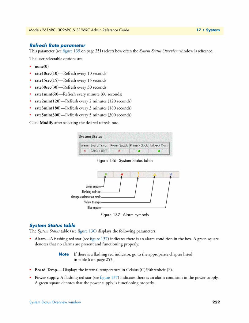
Models 2616RC, 3096RC & 3196RC Admin Reference Guide 17 • System
Refresh Rate parameterThis parameter (see figure 135 on page 251) selects how often the System Status Overview window is refreshed.
The user-selectable options are:
• none(0)
• rate10sec(10)—Refresh every 10 seconds
• rate15sec(15)—Refresh every 15 seconds
• rate30sec(30)—Refresh every 30 seconds
• rate1min(60)—Refresh every minute (60 seconds)
• rate2min(120)—Refresh every 2 minutes (120 seconds)
• rate3min(180)—Refresh every 3 minutes (180 seconds)
• rate5min(300)—Refresh every 5 minutes (300 seconds)
Click Modify after selecting the desired refresh rate.
Figure 136. System Status table
Figure 137. Alarm symbols
System Status tableThe System Status table (see figure 136) displays the following parameters:
• Alarm—A flashing red star (see figure 137) indicates there is an alarm condition in the box. A green square denotes that no alarms are present and functioning properly.
Note If there is a flashing red indicator, go to the appropriate chapter listed in table 6 on page 253.
• Board Temp.—Displays the internal temperature in Celsius (C)/Fahrenheit (F).
• Power supply. A flashing red star (see figure 137) indicates there is an alarm condition in the power supply. A green square denotes that the power supply is functioning properly.
Green squareFlashing red star
Orange exclamation markYellow triangle
Blue square
System Status Overview window 252
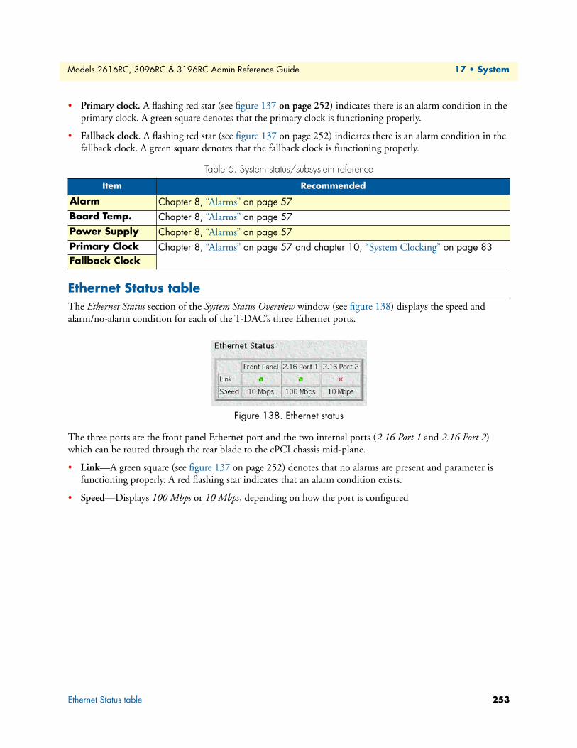
Models 2616RC, 3096RC & 3196RC Admin Reference Guide 17 • System
• Primary clock. A flashing red star (see figure 137 on page 252) indicates there is an alarm condition in the primary clock. A green square denotes that the primary clock is functioning properly.
• Fallback clock. A flashing red star (see figure 137 on page 252) indicates there is an alarm condition in the fallback clock. A green square denotes that the fallback clock is functioning properly.
Ethernet Status tableThe Ethernet Status section of the System Status Overview window (see figure 138) displays the speed and alarm/no-alarm condition for each of the T-DAC’s three Ethernet ports.
Figure 138. Ethernet status
The three ports are the front panel Ethernet port and the two internal ports (2.16 Port 1 and 2.16 Port 2) which can be routed through the rear blade to the cPCI chassis mid-plane.
• Link—A green square (see figure 137 on page 252) denotes that no alarms are present and parameter is functioning properly. A red flashing star indicates that an alarm condition exists.
• Speed—Displays 100 Mbps or 10 Mbps, depending on how the port is configured
Table 6. System status/subsystem reference
Item Recommended
Alarm Chapter 8, “Alarms” on page 57Board Temp. Chapter 8, “Alarms” on page 57Power Supply Chapter 8, “Alarms” on page 57Primary Clock Chapter 8, “Alarms” on page 57 and chapter 10, “System Clocking” on page 83Fallback Clock
Ethernet Status table 253
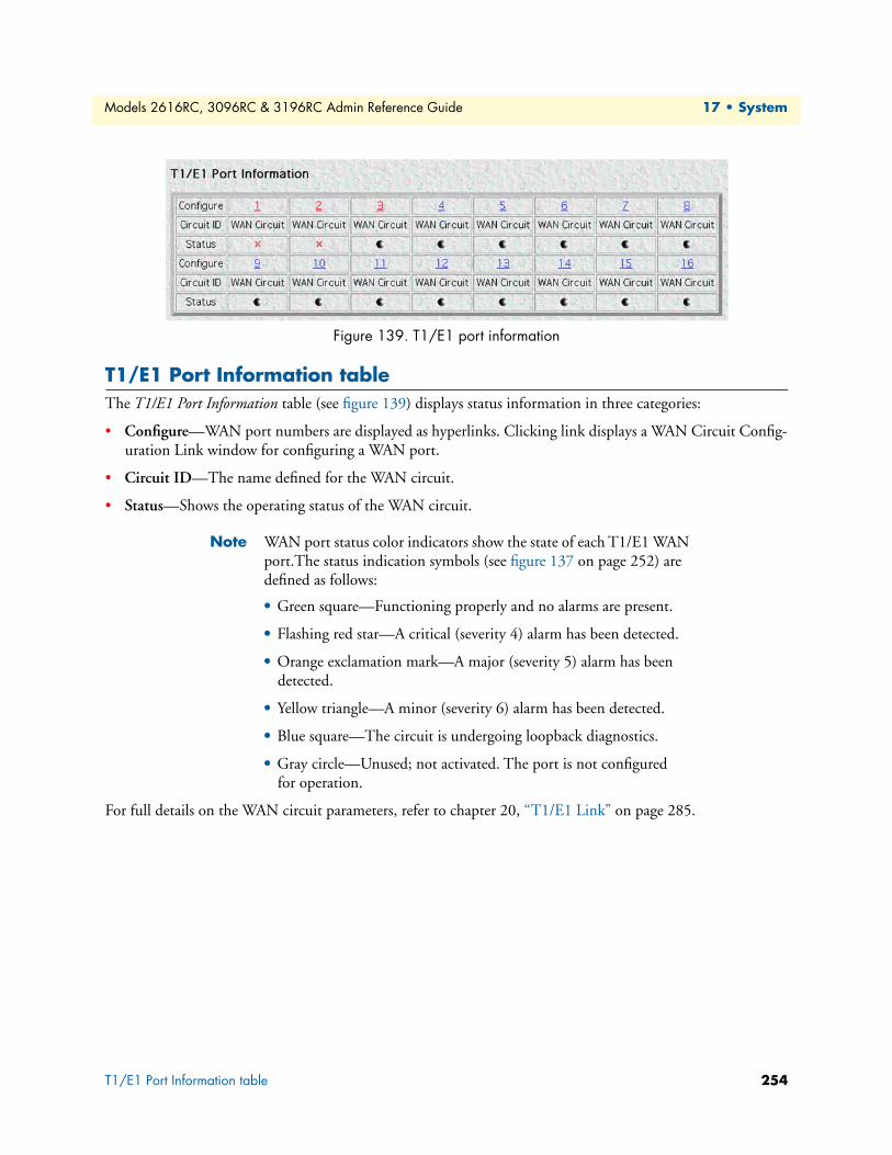
Models 2616RC, 3096RC & 3196RC Admin Reference Guide 17 • System
Figure 139. T1/E1 port information
T1/E1 Port Information table The T1/E1 Port Information table (see figure 139) displays status information in three categories:
• Configure—WAN port numbers are displayed as hyperlinks. Clicking link displays a WAN Circuit Config-uration Link window for configuring a WAN port.
• Circuit ID—The name defined for the WAN circuit.
• Status—Shows the operating status of the WAN circuit.
Note WAN port status color indicators show the state of each T1/E1 WAN port.The status indication symbols (see figure 137 on page 252) are defined as follows:
• Green square—Functioning properly and no alarms are present.
• Flashing red star—A critical (severity 4) alarm has been detected.
• Orange exclamation mark—A major (severity 5) alarm has been detected.
• Yellow triangle—A minor (severity 6) alarm has been detected.
• Blue square—The circuit is undergoing loopback diagnostics.
• Gray circle—Unused; not activated. The port is not configured for operation.
For full details on the WAN circuit parameters, refer to chapter 20, “T1/E1 Link” on page 285.
T1/E1 Port Information table 254
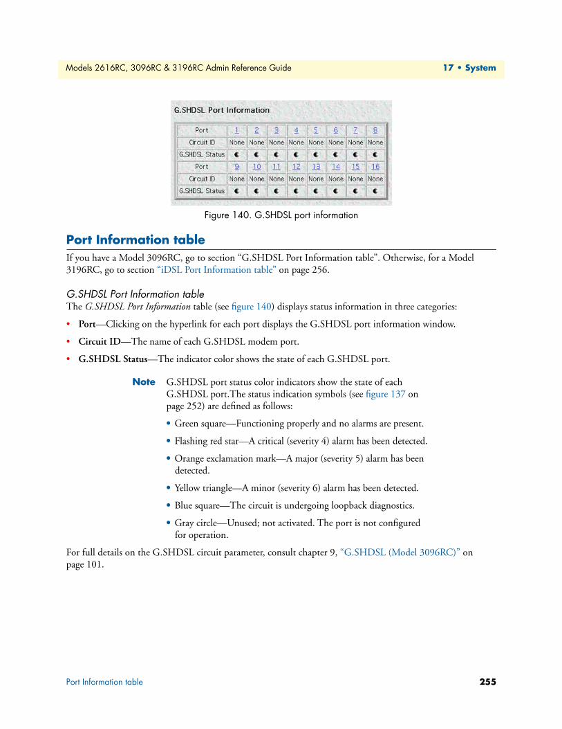
Models 2616RC, 3096RC & 3196RC Admin Reference Guide 17 • System
Figure 140. G.SHDSL port information
Port Information tableIf you have a Model 3096RC, go to section “G.SHDSL Port Information table”. Otherwise, for a Model 3196RC, go to section “iDSL Port Information table” on page 256.
G.SHDSL Port Information tableThe G.SHDSL Port Information table (see figure 140) displays status information in three categories:
• Port—Clicking on the hyperlink for each port displays the G.SHDSL port information window.
• Circuit ID—The name of each G.SHDSL modem port.
• G.SHDSL Status—The indicator color shows the state of each G.SHDSL port.
Note G.SHDSL port status color indicators show the state of each G.SHDSL port.The status indication symbols (see figure 137 on page 252) are defined as follows:
• Green square—Functioning properly and no alarms are present.
• Flashing red star—A critical (severity 4) alarm has been detected.
• Orange exclamation mark—A major (severity 5) alarm has been detected.
• Yellow triangle—A minor (severity 6) alarm has been detected.
• Blue square—The circuit is undergoing loopback diagnostics.
• Gray circle—Unused; not activated. The port is not configured for operation.
For full details on the G.SHDSL circuit parameter, consult chapter 9, “G.SHDSL (Model 3096RC)” on page 101.
Port Information table 255
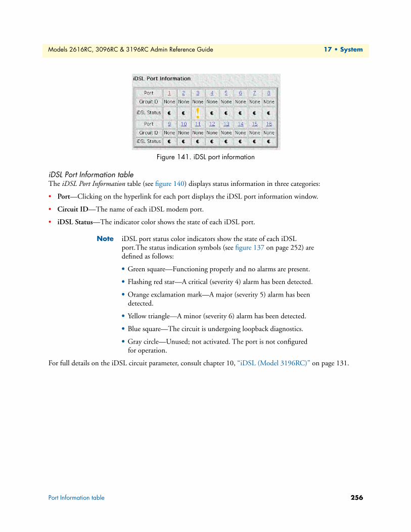
Models 2616RC, 3096RC & 3196RC Admin Reference Guide 17 • System
Figure 141. iDSL port information
iDSL Port Information tableThe iDSL Port Information table (see figure 140) displays status information in three categories:
• Port—Clicking on the hyperlink for each port displays the iDSL port information window.
• Circuit ID—The name of each iDSL modem port.
• iDSL Status—The indicator color shows the state of each iDSL port.
Note iDSL port status color indicators show the state of each iDSL port.The status indication symbols (see figure 137 on page 252) are defined as follows:
• Green square—Functioning properly and no alarms are present.
• Flashing red star—A critical (severity 4) alarm has been detected.
• Orange exclamation mark—A major (severity 5) alarm has been detected.
• Yellow triangle—A minor (severity 6) alarm has been detected.
• Blue square—The circuit is undergoing loopback diagnostics.
• Gray circle—Unused; not activated. The port is not configured for operation.
For full details on the iDSL circuit parameter, consult chapter 10, “iDSL (Model 3196RC)” on page 131.
Port Information table 256
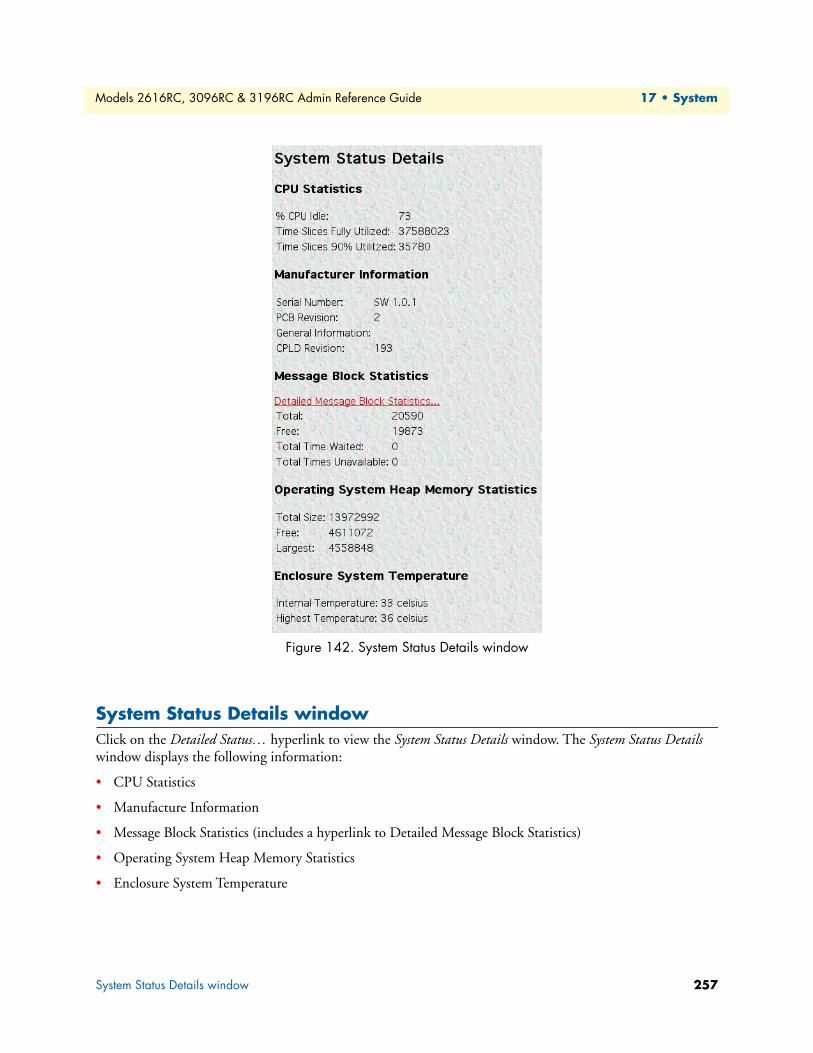
Models 2616RC, 3096RC & 3196RC Admin Reference Guide 17 • System
Figure 142. System Status Details window
System Status Details windowClick on the Detailed Status… hyperlink to view the System Status Details window. The System Status Details window displays the following information:
• CPU Statistics
• Manufacture Information
• Message Block Statistics (includes a hyperlink to Detailed Message Block Statistics)
• Operating System Heap Memory Statistics
• Enclosure System Temperature
System Status Details window 257
Models 2616RC, 3096RC & 3196RC Admin Reference Guide 17 • System
CPU StatisticsThis portion of the System Status Details window, shown in figure 142 on page 257, contains information described in the following sections.
% CPU Idle (boxIdletime)This indicates what percentage of the CPU processing power is not being utilized.
Time Slices Fully Utilized (boxCPUcritical)This value represents a count of how many times the CPU was fully utilized expressed in 1/100th seconds.
Time Slices 90% Utilized (boxCPUWarning)This value represents a count of how many times the CPU approached full utilization expressed in 1/100th seconds.
Manufacturer InformationThis portion of the System Status Details window, shown in figure 142 on page 257, contains manufacturing infor-mation described in the following sections.
Serial Number (boxManufactureDatecode)The serial number.
PCB Revision (boxManufacturePcbRevision)The revision of the printed circuit board.
General Information (boxManufactureGeneralInfo)A manufacturing notes area for additional information.
CPLD Revision (boxCPLrevision)The revision of the complex programmable logic device (CPLD).
Message Block StatisticsThis portion of the System Status Details window, shown in figure 142 on page 257, contains information about the usage of message blocks. A message block is essentially memory available for creating or storing pack-ets where a packet is usually an Ethernet frame. There are four types of message blocks, and each type repre-sents a collection of buffers which are of the same size.
Note Click on the Detailed Message Blocks Statistics… hyperlink to display the System Message Blocks Statistics window and view the statistics (see section “Message Block Statistics” on page 258 for more information).
Total (boxMsgBlksConfigured)The total number of message blocks on the system.
Free (boxMsgBlksFree)The number of free message blocks available.
System Status Details window 258
Models 2616RC, 3096RC & 3196RC Admin Reference Guide 17 • System
Total Time Waited (boxCountMsgBlkTaskWait)The total number of times that the proper size message block was not available to hold a packet, and the CPU task went to sleep while waiting for it.
Total Times Unavailable (boxCountMsgBlkUnavailable)The total number of times that the proper size message block was not available to hold a packet, and the CPU task dumped the packet. The difference between Total Time Waited and Total Times Unavailable is whether the CPU task goes to sleep or simply dumps the packet to continue on.
Operating System Heap Memory StatisticsThis portion of the System Status Details window, shown in figure 142 on page 257, contains information about the memory used by the CPU and its management tasks.
Total Size (boxHeapSize)The size in octets of the operating system heap memory.
Free (boxHeapFreeSpace)The amount of operating system heap memory in octets currently available.
Largest (boxHeapLargestSpace)The largest contiguous memory block in octets in the memory heap.
Enclosure System TemperatureThis portion of the System Status Details window, shown in figure 142 on page 257, contains information about the internal temperature of the T-DAC.
Internal Temperature (boxTemperature)Displays the current temperature in Celsius (centigrade).
Highest Temperature (boxMaxTemperature)The highest temperature registered in Celsius (centigrade) since the T-DAC was last re-booted.
System Status Details window 259
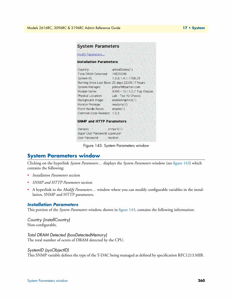
Models 2616RC, 3096RC & 3196RC Admin Reference Guide 17 • System
Figure 143. System Parameters window
System Parameters windowClicking on the hyperlink System Parameters… displays the System Parameters window (see figure 143) which contains the following:
• Installation Parameters section
• SNMP and HTTP Parameters section
• A hyperlink to the Modify Parameters… window where you can modify configurable variables in the instal-lation, SNMP and HTTP parameters.
Installation ParametersThis portion of the System Parameters window, shown in figure 143, contains the following information:
Country (installCountry)Non-configurable.
Total DRAM Detected (boxDetectedMemory)The total number of octets of DRAM detected by the CPU.
SystemID (sysObjectID)This SNMP variable defines the type of the T-DAC being managed as defined by specification RFC1213.MIB.
System Parameters window 260
Models 2616RC, 3096RC & 3196RC Admin Reference Guide 17 • System
Running Since Last Boot (sysUpTime)This SNMP variable represents the time since the network management portion of the system was last re-initialized.
System Manager (sysContact)This SNMP variable represents the textual identification of the contact person for this managed node, which may include information on how to contact this person as defined by specification RFC1213.MIB. The maxi-mum length of this field is 256 octets.
Module Name (sysName)This is “An administratively assigned name for this managed node. By convention, this is the node’s fully-qualified domain name.” (RFC1213.MIB).
Physical Location (sysLocation)“The physical location of this node (e.g., telephone closet, 3rd floor).” (RFC1213.MIB).
Background Image (boxBackgroundFlag)The following options are available:
• disableGraphics(0)—When this option is selected, graphics on WWW pages will not be displayed. This results in faster page display times, but may make it more difficult to navigate WWW sites that rely heavily on graphics.
• enableGraphics(1)—When this option is selected, graphics on WWW pages are displayed.
• disableWeb(2)—When this option is selected, access to the WWW pages is denied for everyone.
Monitor Privilege (boxMonitorPrivilege)Specifies the privileges given to the monitor user. Privileges can be removed or additional write access can be given beyond read-only access. The following options are available:
• none(0)—The monitor user can not log in.
• read only(2)—This is the default setting. The monitor user can view but not change any parameters. Mon-itor can not view passwords.
• writeUser(18)—Not supported.
• writeUserlp(50)—The monitor user can change all parameters—except passwords and IP links.
• writeUserlpWan(114)—The monitor user can change all parameters—except passwords, and IP, and T1/E1.
• writeUserlpWanSystem(242)—The monitor user can change all parameters—except passwords, IP, T1/ E1, System, and System Log links.
• writeUserlpWanSystemUpload(498)—The monitor user can change all parameters—except passwords, IP, T1/E1, System, and System Log links. The monitor user can also load firmware updates into the T-DAC.
System Parameters window 261
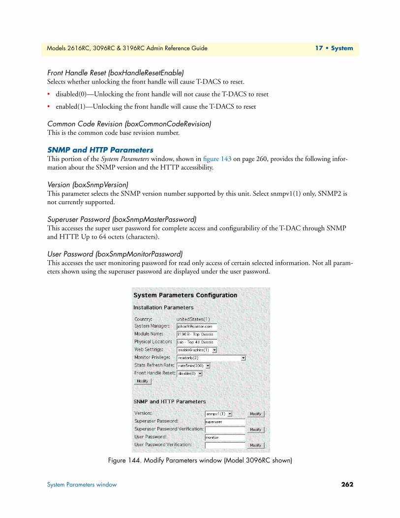
Models 2616RC, 3096RC & 3196RC Admin Reference Guide 17 • System
Front Handle Reset (boxHandleResetEnable)Selects whether unlocking the front handle will cause T-DACS to reset.
• disabled(0)—Unlocking the front handle will not cause the T-DACS to reset
• enabled(1)—Unlocking the front handle will cause the T-DACS to reset
Common Code Revision (boxCommonCodeRevision)This is the common code base revision number.
SNMP and HTTP ParametersThis portion of the System Parameters window, shown in figure 143 on page 260, provides the following infor-mation about the SNMP version and the HTTP accessibility.
Version (boxSnmpVersion)This parameter selects the SNMP version number supported by this unit. Select snmpv1(1) only, SNMP2 is not currently supported.
Superuser Password (boxSnmpMasterPassword)This accesses the super user password for complete access and configurability of the T-DAC through SNMP and HTTP. Up to 64 octets (characters).
User Password (boxSnmpMonitorPassword)This accesses the user monitoring password for read only access of certain selected information. Not all param-eters shown using the superuser password are displayed under the user password.
Figure 144. Modify Parameters window (Model 3096RC shown)
System Parameters window 262
Models 2616RC, 3096RC & 3196RC Admin Reference Guide 17 • System
Modify Parameters windowThe System Parameters Configuration window (see figure 144) provides the means for you to modify the values for T-DAC System configurable parameters in the SNMP and HTTP, and Installation tables. To display the System (configurable parameters) window, on the System Parameters window, click the Modify Parameters… link (see figure 143 on page 260).
The following sections describe the configurable parameters displayed on the System Parameters Configuration window.
InstallationThis portion of the System window shown in figure 144 on page 262 contains information described in the following sections.
System Manager (sysContact)This SNMP variable represents the textual identification of the contact person for this managed node, together with information on how to contact this person as defined by specification RFC1213.MIB.
Module Name (sysName)This is “An administratively assigned name for this managed node. By convention, this is the node’s fully-qualified domain name.” (RFC1213.MIB)
Physical Location (sysLocation)“The physical location of this node (e.g., ‘telephone closet, 3rd floor’).” (RFC1213.MIB)
Web Settings (boxBackgroundFlag)The following options are available:
disableGraphics(0)—When this option is selected, graphics on WWW pages will not be displayed. This results in faster page display times, but may make it more difficult to navigate WWW sites that rely heavily on graphics.
enableGraphics(1)—When this option is selected, graphics on WWW pages are displayed.
disableWeb(2)—When this option is selected, access to the WWW pages is denied for everyone.
Monitor Privilege (boxMonitorPrivilege)Specifies the privileges given to the monitor user. Privileges can be removed or additional write access can be given beyond read-only access. The following options are available:
• none(0)—The monitor user can not log in.
• read only(2)—This is the default setting. The monitor user can view but not change any parameters. Mon-itor can not view passwords.
• writeUser(18)—The monitor user can change all parameters—except passwords— under authentication, drop-and-insert, and dial-in links.
• writeUserlp(50)—The monitor user can change all parameters—except passwords— under authentication, drop-and-insert, dial-in, and IP links.
System Parameters window 263
Models 2616RC, 3096RC & 3196RC Admin Reference Guide 17 • System
• writeUserlpWan(114)—The monitor user can change all parameters—except passwords— under authenti-cation, drop-and-insert, dial-in, IP, T1/E1, and Frame Relay links.
• writeUserlpWanSystem(242)—The monitor user can change all parameters—except passwords— under authentication, drop-and-insert, dial-in, IP, T1/E1, Frame Relay, System, and System Log links.
• writeUserlpWanSystemUpload(498)—The monitor user can change all parameters—except passwords— under authentication, drop-and-insert, dial-in, IP, T1/E1, Frame Relay, System, and System Log links. The monitor user can also load firmware updates into the DACS.
Stats Refresh Rate (boxWebRefreshRate)Specifies statistics refresh rate in seconds and minutes. The following options are available:
• none(0)—No automatic refresh
• rate10sec—Statistics refreshed every 10 seconds
• rate15sec—Statistics refreshed every 15 seconds
• rate30sec—Statistics refreshed every 30 seconds
• rate1min—Statistics refreshed every minute
• rate3min—Statistics refreshed every 3 minutes
• rate5min—Statistics refreshed every 5 minutes
Front Handle ResetSpecifies whether unlocking the front handle will cause the T-DACS to reset. The available options are:
• disable(0)—T-DACS will not reset upon unlocking the right front handle
• enable(1)—T-DACS will reset upon unlocking the right front handle
SNMP and HTTPThis portion of the System window shown in figure 144 on page 262 provides information about the SNMP ver-sion and the HTTP accessibility.
Version (boxSnmpVersion)This parameter selects the SNMP version number supported by this unit. Select snmpv1(1) only, SNMP2 is not currently supported.
Superuser Password (boxSnmpMasterPassword)This accesses the super user password for complete access and configurability of the T-DAC through SNMP and HTTP. Up to 64 octets (characters).
Superuser Password Verification (boxSnmpVerifyMasterPassword)This is verification for the password. It must be set before replacing the old password with the new one.
User Password (boxSnmpMonitorPassword)This accesses the user monitoring password for read only access of certain selected information. Not all param-eters shown using the superuser password are displayed under the user password.
System Parameters window 264
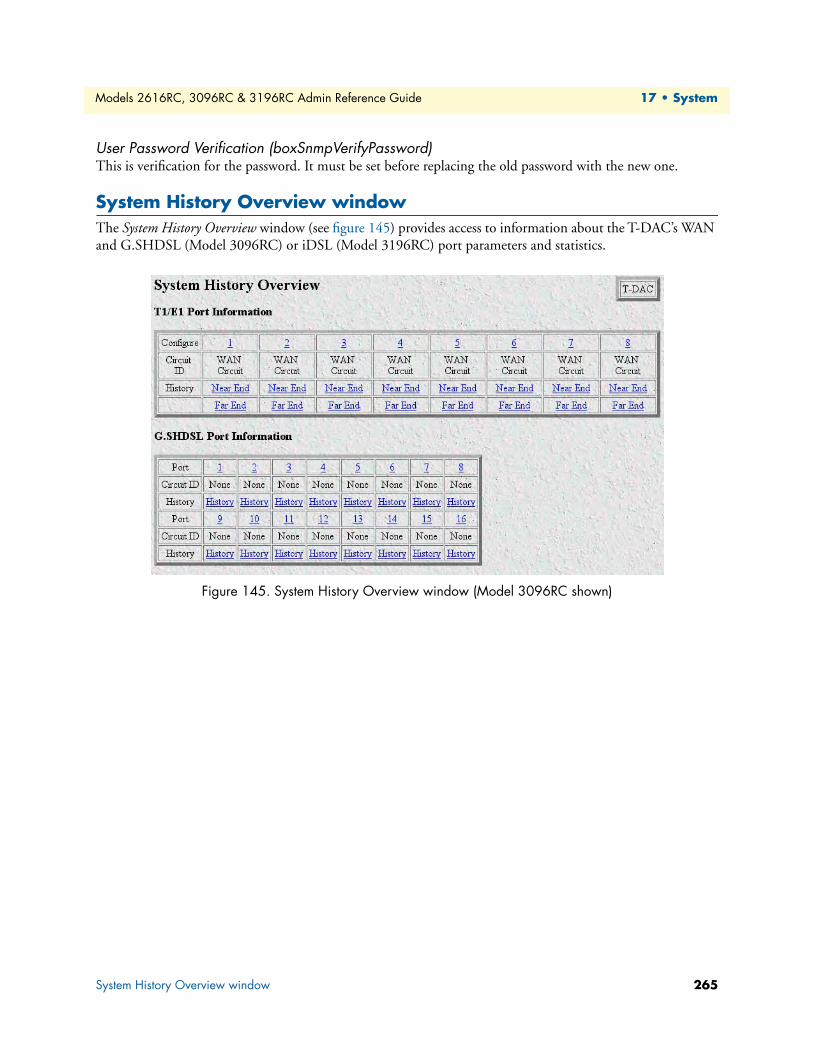
Models 2616RC, 3096RC & 3196RC Admin Reference Guide 17 • System
User Password Verification (boxSnmpVerifyPassword)This is verification for the password. It must be set before replacing the old password with the new one.
System History Overview windowThe System History Overview window (see figure 145) provides access to information about the T-DAC’s WAN and G.SHDSL (Model 3096RC) or iDSL (Model 3196RC) port parameters and statistics.
Figure 145. System History Overview window (Model 3096RC shown)
System History Overview window 265
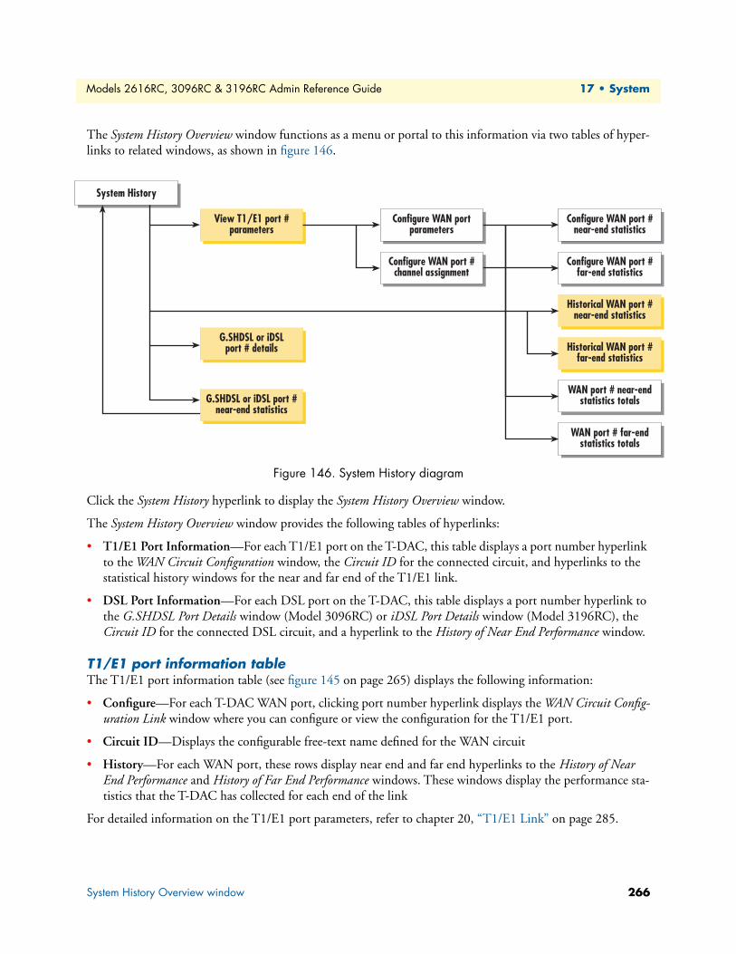
Models 2616RC, 3096RC & 3196RC Admin Reference Guide 17 • System
The System History Overview window functions as a menu or portal to this information via two tables of hyper-links to related windows, as shown in figure 146.
Figure 146. System History diagram
Click the System History hyperlink to display the System History Overview window.
The System History Overview window provides the following tables of hyperlinks:
• T1/E1 Port Information—For each T1/E1 port on the T-DAC, this table displays a port number hyperlink to the WAN Circuit Configuration window, the Circuit ID for the connected circuit, and hyperlinks to the statistical history windows for the near and far end of the T1/E1 link.
• DSL Port Information—For each DSL port on the T-DAC, this table displays a port number hyperlink to the G.SHDSL Port Details window (Model 3096RC) or iDSL Port Details window (Model 3196RC), the Circuit ID for the connected DSL circuit, and a hyperlink to the History of Near End Performance window.
T1/E1 port information tableThe T1/E1 port information table (see figure 145 on page 265) displays the following information:
• Configure—For each T-DAC WAN port, clicking port number hyperlink displays the WAN Circuit Config-uration Link window where you can configure or view the configuration for the T1/E1 port.
• Circuit ID—Displays the configurable free-text name defined for the WAN circuit
• History—For each WAN port, these rows display near end and far end hyperlinks to the History of Near End Performance and History of Far End Performance windows. These windows display the performance sta-tistics that the T-DAC has collected for each end of the link
For detailed information on the T1/E1 port parameters, refer to chapter 20, “T1/E1 Link” on page 285.
System History
View T1/E1 port #parameters
Configure WAN port #near-end statistics
Configure WAN port #far-end statistics
Historical WAN port #near-end statistics
Historical WAN port #far-end statistics
WAN port # near-endstatistics totals
WAN port # far-endstatistics totals
G.SHDSL or iDSLport # details
G.SHDSL or iDSL port #near-end statistics
Configure WAN portparameters
Configure WAN port #channel assignment
System History Overview window 266
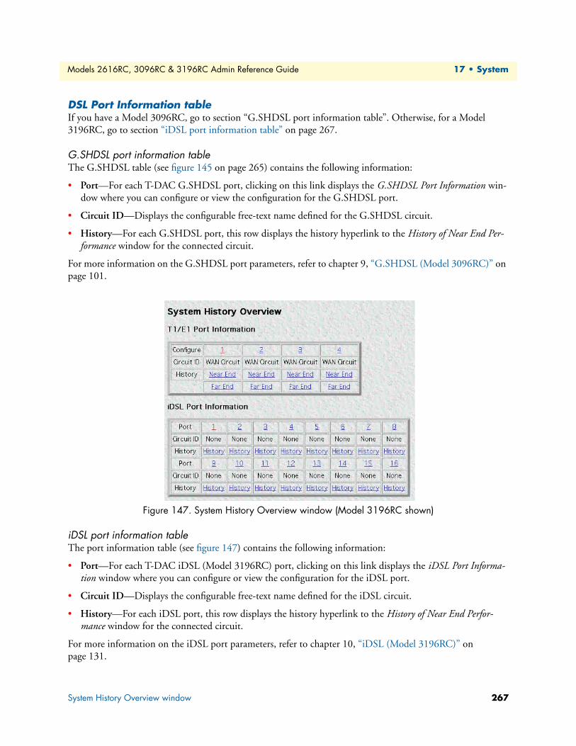
Models 2616RC, 3096RC & 3196RC Admin Reference Guide 17 • System
DSL Port Information tableIf you have a Model 3096RC, go to section “G.SHDSL port information table”. Otherwise, for a Model 3196RC, go to section “iDSL port information table” on page 267.
G.SHDSL port information tableThe G.SHDSL table (see figure 145 on page 265) contains the following information:
• Port—For each T-DAC G.SHDSL port, clicking on this link displays the G.SHDSL Port Information win-dow where you can configure or view the configuration for the G.SHDSL port.
• Circuit ID—Displays the configurable free-text name defined for the G.SHDSL circuit.
• History—For each G.SHDSL port, this row displays the history hyperlink to the History of Near End Per-formance window for the connected circuit.
For more information on the G.SHDSL port parameters, refer to chapter 9, “G.SHDSL (Model 3096RC)” on page 101.
Figure 147. System History Overview window (Model 3196RC shown)
iDSL port information tableThe port information table (see figure 147) contains the following information:
• Port—For each T-DAC iDSL (Model 3196RC) port, clicking on this link displays the iDSL Port Informa-tion window where you can configure or view the configuration for the iDSL port.
• Circuit ID—Displays the configurable free-text name defined for the iDSL circuit.
• History—For each iDSL port, this row displays the history hyperlink to the History of Near End Perfor-mance window for the connected circuit.
For more information on the iDSL port parameters, refer to chapter 10, “iDSL (Model 3196RC)” on page 131.
System History Overview window 267
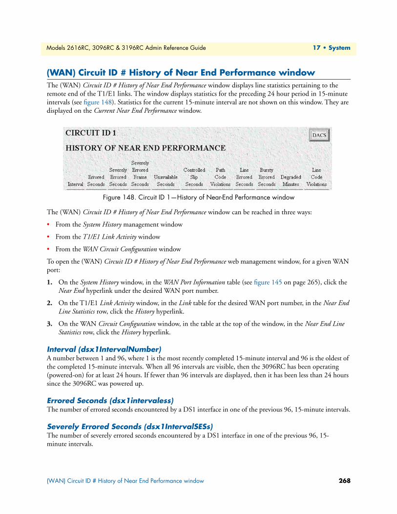
Models 2616RC, 3096RC & 3196RC Admin Reference Guide 17 • System
(WAN) Circuit ID # History of Near End Performance windowThe (WAN) Circuit ID # History of Near End Performance window displays line statistics pertaining to the remote end of the T1/E1 links. The window displays statistics for the preceding 24 hour period in 15-minute intervals (see figure 148). Statistics for the current 15-minute interval are not shown on this window. They are displayed on the Current Near End Performance window.
Figure 148. Circuit ID 1—History of Near-End Performance window
The (WAN) Circuit ID # History of Near End Performance window can be reached in three ways:
• From the System History management window
• From the T1/E1 Link Activity window
• From the WAN Circuit Configuration window
To open the (WAN) Circuit ID # History of Near End Performance web management window, for a given WAN port:
1. On the System History window, in the WAN Port Information table (see figure 145 on page 265), click the Near End hyperlink under the desired WAN port number.
2. On the T1/E1 Link Activity window, in the Link table for the desired WAN port number, in the Near End Line Statistics row, click the History hyperlink.
3. On the WAN Circuit Configuration window, in the table at the top of the window, in the Near End Line Statistics row, click the History hyperlink.
Interval (dsx1IntervalNumber)A number between 1 and 96, where 1 is the most recently completed 15-minute interval and 96 is the oldest of the completed 15-minute intervals. When all 96 intervals are visible, then the 3096RC has been operating (powered-on) for at least 24 hours. If fewer than 96 intervals are displayed, then it has been less than 24 hours since the 3096RC was powered up.
Errored Seconds (dsx1intervaless)The number of errored seconds encountered by a DS1 interface in one of the previous 96, 15-minute intervals.
Severely Errored Seconds (dsx1IntervalSESs)The number of severely errored seconds encountered by a DS1 interface in one of the previous 96, 15-minute intervals.
(WAN) Circuit ID # History of Near End Performance window 268

Models 2616RC, 3096RC & 3196RC Admin Reference Guide 17 • System
Severely Errored Frame Seconds (dsx1IntervalSEFSs)The number of severely errored framing seconds encountered by a DS1 interface in one of the previous 96, 15-minute intervals.
Unavailable Seconds (dsx1IntervalUASs)The number of unavailable seconds encountered by a DS1 interface in one of the previous 96, 15-minute intervals.
Controlled Slip Seconds (dsx1IntervalCSSs)The number of controlled slip seconds encountered by a DS1 interface in one of the previous 96, 15-minute intervals.
Path Code Violations (dsx1IntervalPCVs)The number of path coding violations encountered by a DS1 interface in one of the previous 96, 15-minute intervals.
Line Errored Seconds (dsx1IntervalLESs)The number of line errored seconds encountered by a DS1 interface in one of the previous 96, 15-minute intervals.
Bursty Errored Seconds (dsx1IntervalBESs)The number of bursty errored seconds (BESs) encountered by a DS1 interface in one of the previous 96, 15-minute intervals.
Degraded Minutes (dsx1IntervalDMs)The number of degraded minutes (DMs) encountered by a DS1 interface in one of the previous 96, 15-minute intervals.
Line Code Violations (dsx1IntervalLCVs)The number of line code violations (LCVs) encountered by a DS1 interface during the current 15-minute interval.
(WAN) Circuit ID # History of Near End Performance window 269

Models 2616RC, 3096RC & 3196RC Admin Reference Guide 17 • System
History of Near End Performance: G.SHDSL or iDSL Port windowThe History of Near End Performance: G.SHDSL or iDSL Port window displays line statistics pertaining to the near end of a G.SHDSL/iDSL link. The page displays statistics for the preceding 24 hour period in 15-minute intervals (see figure 149). The T-DAC cannot display statistics for the current 15-minute interval.
Figure 149. G.SHDSL History of Near End Performance window
The History of Near End Performance: G.SHDSL Port window may be reached in two ways:
• From the System History management window
• From the G.SHDSL Port Details window
To open the (WAN) Circuit ID # History of Near End Performance window, for a given WAN port, do the following:
• On the System History window, in the G.SHDSL History table, click the History hyperlink under the desired G.SHDSL port number.
• On the G.SHDSL Port Details window, click the History Details hyperlink.
The History of Near End Performance: G.SHDSL Port window displays the following information:
• G.SHDSL Port #—Identifies by T-DAC port number the G.SHDSL link for which statistics are shown.
• Back to System History Page hyperlink—Clicking on this link will return you to the System History manage-ment page.
• To Port Details Page hyperlink—Clicking on this link will return you to the G.SHDSL Port Details window for the specified G.SHDSL port number.
Interval (gshDSLIntervalNumber)A number between 1 and 96, where 1 is the most recently completed 15-minute interval and 96 is the oldest completed 15-minute interval (assuming that all 96 intervals are valid).
Errored Seconds (historyESgshDSL)The number of far-end errored seconds encountered by a G.SHDSL interface in one of the previous 96, 15-minute intervals.
History of Near End Performance: G.SHDSL or iDSL Port window 270

Models 2616RC, 3096RC & 3196RC Admin Reference Guide 17 • System
Severely Errored Seconds (historySESgshDSL)The number of far-end severely errored seconds encountered by a G.SHDSL interface in one of the previous 96, 15-minute intervals.
Unavailable Seconds (historyUASgshDSL)The number of far-end unavailable seconds encountered by a G.SHDSL interface in one of the previous 96, 15-minute intervals.
History of Near End Performance: G.SHDSL or iDSL Port window 271

Chapter 18 Alarm Card
Chapter contentsIntroduction ........................................................................................................................................................273Alarm Card Status ...............................................................................................................................................273
272
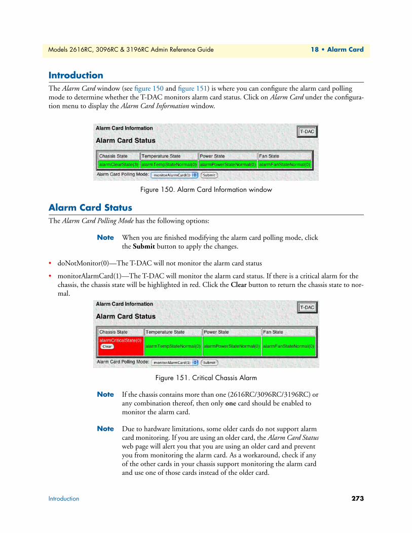
Models 2616RC, 3096RC & 3196RC Admin Reference Guide 18 • Alarm Card
IntroductionThe Alarm Card window (see figure 150 and figure 151) is where you can configure the alarm card polling mode to determine whether the T-DAC monitors alarm card status. Click on Alarm Card under the configura-tion menu to display the Alarm Card Information window.
Figure 150. Alarm Card Information window
Alarm Card StatusThe Alarm Card Polling Mode has the following options:
Note When you are finished modifying the alarm card polling mode, click the Submit button to apply the changes.
• doNotMonitor(0)—The T-DAC will not monitor the alarm card status
• monitorAlarmCard(1)—The T-DAC will monitor the alarm card status. If there is a critical alarm for the chassis, the chassis state will be highlighted in red. Click the Clear button to return the chassis state to nor-mal.
Figure 151. Critical Chassis Alarm
Note If the chassis contains more than one (2616RC/3096RC/3196RC) or any combination thereof, then only one card should be enabled to monitor the alarm card.
Note Due to hardware limitations, some older cards do not support alarm card monitoring. If you are using an older card, the Alarm Card Status web page will alert you that you are using an older card and prevent you from monitoring the alarm card. As a workaround, check if any of the other cards in your chassis support monitoring the alarm card and use one of those cards instead of the older card.
Introduction 273
Chapter 19 System Log
Chapter contentsIntroduction ........................................................................................................................................................275System Log Overview window.............................................................................................................................275
Hyperlinks ....................................................................................................................................................276System Log Parameters .................................................................................................................................277
SysLog Daemon IP Address(syslogDaemonIP) ........................................................................................277SNMP Trap Daemon IP Address (syslogTrapIP) ....................................................................................277Min Priority for SysLog Daemon (syslogDaemonPriority) ......................................................................277Min Priority for Console RS-232 (syslogConsolePriority) .......................................................................278Min Priority for Flash Storage (syslogFlashPriority) ................................................................................278Min Priority for SNMP Trap Daemon (syslogTrapPriority) ...................................................................278Min Priority for RAM (SyslogTablePriority) ...........................................................................................279Unix Facility (syslogUnixFacility) ...........................................................................................................279Call Trace (syslogCallTrace) ....................................................................................................................279Maintain Flash Storage (syslogFlashClear) ...............................................................................................279
System Log Configuration window......................................................................................................................280Daemons ......................................................................................................................................................280
SysLog Daemon IP Address(syslogDaemonIP) ........................................................................................281SNMP Trap Daemon IP Address (syslogTrapIP) ....................................................................................281
Priority .........................................................................................................................................................281Min Priority for SysLog Daemon (syslogDaemonPriority) ......................................................................281Min Priority for Console RS-232 (syslogConsolePriority) .......................................................................281Min Priority for Flash Storage (syslogFlashPriority) ................................................................................282Min Priority for SNMP Trap Daemon (syslogTrapPriority) ...................................................................282Min Priority for RAM (SyslogTablePriority) ...........................................................................................282
Unix Facility (syslogUnixFacility) ...........................................................................................................283Call Trace (syslogCallTrace) ....................................................................................................................283
System Log Messages in Volatile Memory window..............................................................................................283DRAM Message Cache .................................................................................................................................283
Time (slTick) ..........................................................................................................................................283Message (slMessage) ................................................................................................................................283
System Log Messages in Non-Volatile Memory window .....................................................................................284Message Cache Management ........................................................................................................................284
Cache Full Status ....................................................................................................................................284Clear Syslog Message Cache ....................................................................................................................284
Syslog Messages ............................................................................................................................................284Time (slfTick) .........................................................................................................................................284Message (slfMessage) ...............................................................................................................................284
274
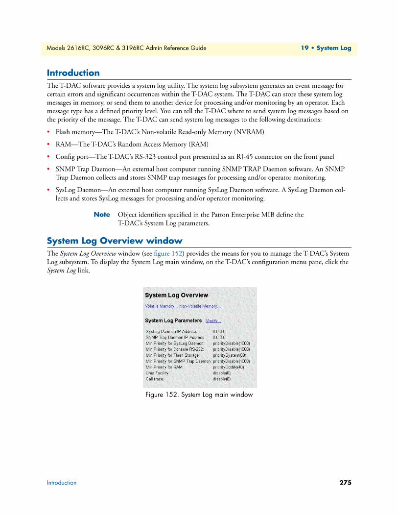
Models 2616RC, 3096RC & 3196RC Admin Reference Guide 19 • System Log
IntroductionThe T-DAC software provides a system log utility. The system log subsystem generates an event message for certain errors and significant occurrences within the T-DAC system. The T-DAC can store these system log messages in memory, or send them to another device for processing and/or monitoring by an operator. Each message type has a defined priority level. You can tell the T-DAC where to send system log messages based on the priority of the message. The T-DAC can send system log messages to the following destinations:
• Flash memory—The T-DAC’s Non-volatile Read-only Memory (NVRAM)
• RAM—The T-DAC’s Random Access Memory (RAM)
• Config port—The T-DAC’s RS-323 control port presented as an RJ-45 connector on the front panel
• SNMP Trap Daemon—An external host computer running SNMP TRAP Daemon software. An SNMP Trap Daemon collects and stores SNMP trap messages for processing and/or operator monitoring.
• SysLog Daemon—An external host computer running SysLog Daemon software. A SysLog Daemon col-lects and stores SysLog messages for processing and/or operator monitoring.
Note Object identifiers specified in the Patton Enterprise MIB define the T-DAC’s System Log parameters.
System Log Overview windowThe System Log Overview window (see figure 152) provides the means for you to manage the T-DAC’s System Log subsystem. To display the System Log main window, on the T-DAC’s configuration menu pane, click the System Log link.
Figure 152. System Log main window
Introduction 275

Models 2616RC, 3096RC & 3196RC Admin Reference Guide 19 • System Log
The System Log main window provides hyperlinks to the System Log (configuration), System Log (volatile Memory) and System Log (Non-Volatile Memory) windows, as shown in figure 153.
Figure 153. System Log windows map
You can use the System Log Overview windows to
• View and define configurable parameters that control the operation of the System Log subsystem
• View the System Log messages the T-DAC currently stores in
- Volatile Memory
- Non-Volatile memory
The following sections describe the contents of the System Log Overview window.
Figure 154. Hyperlinks section of the System Log Overview window
HyperlinksThe System Log Overview window displays the following hyperlinks (see figure 154):
• Modify—Clicking on the Modify… link next to the System Log Parameters displays the System Log Configu-ration window. You can use the System Log Configuration window to view and modify the values of syslog configurable parameters. The System Log Configuration window is described in section “System Log Config-uration window” on page 280
• Volatile Memory—Clicking on the Volatile Memory… link displays the System Log Messages in Volatile Mem-ory window, where you can view the system log messages currently stored in the T-DAC’s volatile Direct Random Access Memory (DRAM). The System Log Messages in Volatile Memory window is described in sec-tion “System Log Messages in Volatile Memory window” on page 283
System LogConfiguration (Modify)
System Log
System LogVolatile Memory
System LogNon-Volatile Memory
System Log Overview window 276
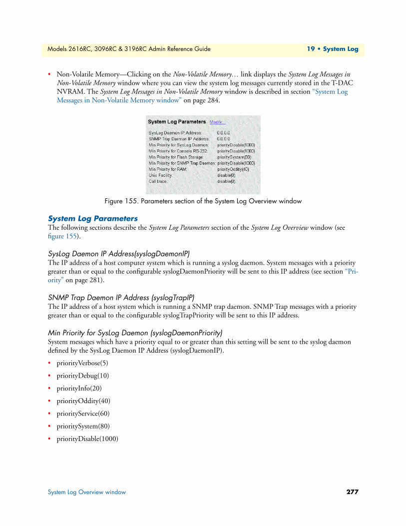
Models 2616RC, 3096RC & 3196RC Admin Reference Guide 19 • System Log
• Non-Volatile Memory—Clicking on the Non-Volatile Memory… link displays the System Log Messages in Non-Volatile Memory window where you can view the system log messages currently stored in the T-DAC NVRAM. The System Log Messages in Non-Volatile Memory window is described in section “System Log Messages in Non-Volatile Memory window” on page 284.
Figure 155. Parameters section of the System Log Overview window
System Log ParametersThe following sections describe the System Log Parameters section of the System Log Overview window (see figure 155).
SysLog Daemon IP Address(syslogDaemonIP)The IP address of a host computer system which is running a syslog daemon. System messages with a priority greater than or equal to the configurable syslogDaemonPriority will be sent to this IP address (see section “Pri-ority” on page 281).
SNMP Trap Daemon IP Address (syslogTrapIP)The IP address of a host system which is running a SNMP trap daemon. SNMP Trap messages with a priority greater than or equal to the configurable syslogTrapPriority will be sent to this IP address.
Min Priority for SysLog Daemon (syslogDaemonPriority)System messages which have a priority equal to or greater than this setting will be sent to the syslog daemon defined by the SysLog Daemon IP Address (syslogDaemonIP).
• priorityVerbose(5)
• priorityDebug(10)
• priorityInfo(20)
• priorityOddity(40)
• priorityService(60)
• prioritySystem(80)
• priorityDisable(1000)
System Log Overview window 277
Models 2616RC, 3096RC & 3196RC Admin Reference Guide 19 • System Log
Min Priority for Console RS-232 (syslogConsolePriority) System messages which have a priority equal to or greater than this setting will be sent directly to the RS-232 Config control port (RJ-45 connector labeled “Config”) on the front panel of the T-DAC. Messages will be sent regardless of the current operating state of the RS- 232 configuration port. The lower the number next to the priority listed below, the more details system logging will provide. priorityVerbose will generate the most messages, while priorityDisable will turn off all messages.
• priorityVerbose(5)
• priorityDebug(10)
• priorityInfo(20)
• priorityOddity(40)
• priorityService(60)
• prioritySystem(80)
• priorityDisable(1000)
Min Priority for Flash Storage (syslogFlashPriority)System messages which have a priority equal to or greater than this setting will be permanently stored in the Flash PROM. Due to being permanent memory, the Flash memory eventually becomes filled. When this occurs, the memory must be cleared before accepting more messages. Some maximum number of messages may be stored in the Flash PROM before this storage area must be cleared.
• prioritySystem(80)—Flash PROM will be used to store system-level messages.
• priorityDisable(1000)—No messages will be stored.
Min Priority for SNMP Trap Daemon (syslogTrapPriority)System messages which have a priority equal to or greater than this setting will be sent to the SNMP Trap Dae-mon IP Address (syslogTrapIP). The lower the number next to the priority listed below, the more details sys-tem logging will provide. Selecting priorityVerbose will generate the most messages, while selecting priorityDisable will turn off all messages.
• priorityVerbose(5)
• priorityDebug(10)
• priorityInfo(20)
• priorityOddity(40)
• priorityService(60)
• prioritySystem(80)
• priorityDisable(1000)
System Log Overview window 278
Models 2616RC, 3096RC & 3196RC Admin Reference Guide 19 • System Log
Min Priority for RAM (SyslogTablePriority)System messages which have a priority equal to or greater than this setting will appear in System Log—Volatile Memory. The lower the number next to the priority listed below, the more details system logging will provide. Selecting priorityVerbose will generate the most messages, while selecting priorityDisable will turn off all messages.
• priorityVerbose(5)
• priorityDebug(10)
• priorityInfo(20)
• priorityOddity(40)
• priorityService(60)
• prioritySystem(80)
• priorityDisable(1000)
Unix Facility (syslogUnixFacility)This setting is used when syslog messages are sent to a Unix-type syslog daemon. In this case the message will include the facility and priority coding.
Call Trace (syslogCallTrace)Enabling this will activate the call tracing utility. This is a powerful debugging utility which will log every sin-gle function call and return. At the death of a box the call trace will be printed out and can be sent to tech sup-port. This utility will take a large amount of CPU power.
• disable(0)—Disable function call tracing.
• enable(1)—Enable function call tracing.
• dump(2)—Display function call tracing on the computer monitor.
Maintain Flash Storage (syslogFlashClear)This parameter provides two functions:
• You can read the value of this parameter to learn the status of the System Log Message cache in flash mem-ory.
• You can set the value to syslogFlashClear to erase (clear) the messages in the System Log Message cache in flash memory.
The following values are defined:
• syslogFlashOK(0)—As long as the T-DAC’s flash memory is accepting system log messages, the T-DAC will set the value of syslogFlashClear(2) to syslogFlashOK(0).
• disable(0) • user(1) • mail(2) • daemon(3) • auth(4) • syslog(5)
• lpr(6) • news(7) • uucp(8) • cron(9) • authpriv(10) • ftp(11)
• local0(16) • local1(17) • local2(18) • local3(19) • local4(20) • local5(21)
• local6(22) • local7(23)
System Log Overview window 279
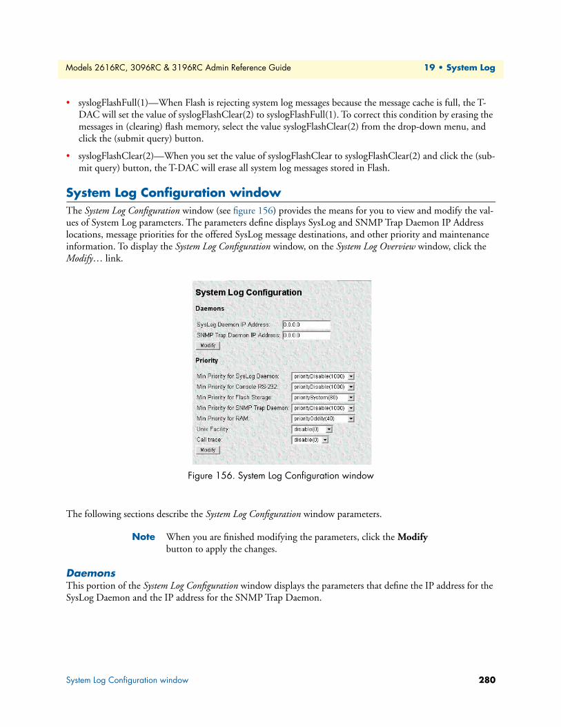
Models 2616RC, 3096RC & 3196RC Admin Reference Guide 19 • System Log
• syslogFlashFull(1)—When Flash is rejecting system log messages because the message cache is full, the T-DAC will set the value of syslogFlashClear(2) to syslogFlashFull(1). To correct this condition by erasing the messages in (clearing) flash memory, select the value syslogFlashClear(2) from the drop-down menu, and click the (submit query) button.
• syslogFlashClear(2)—When you set the value of syslogFlashClear to syslogFlashClear(2) and click the (sub-mit query) button, the T-DAC will erase all system log messages stored in Flash.
System Log Configuration windowThe System Log Configuration window (see figure 156) provides the means for you to view and modify the val-ues of System Log parameters. The parameters define displays SysLog and SNMP Trap Daemon IP Address locations, message priorities for the offered SysLog message destinations, and other priority and maintenance information. To display the System Log Configuration window, on the System Log Overview window, click the Modify… link.
Figure 156. System Log Configuration window
The following sections describe the System Log Configuration window parameters.
Note When you are finished modifying the parameters, click the Modify button to apply the changes.
DaemonsThis portion of the System Log Configuration window displays the parameters that define the IP address for the SysLog Daemon and the IP address for the SNMP Trap Daemon.
System Log Configuration window 280
Models 2616RC, 3096RC & 3196RC Admin Reference Guide 19 • System Log
SysLog Daemon IP Address(syslogDaemonIP)The IP address of a host computer system which is running a syslog daemon. System messages with a priority greater than or equal to the configurable syslogDaemonPriority will be sent to this IP address (see section “Pri-ority” on page 281).
SNMP Trap Daemon IP Address (syslogTrapIP)The IP address of a host system which is running a SNMP trap daemon. SNMP Trap messages with a priority greater than or equal to the configurable syslogTrapPriority will be sent to this IP address.
PriorityThis portion of the System Log Configuration window displays the parameters that define the Message Priority level for the System Log message destinations.
Min Priority for SysLog Daemon (syslogDaemonPriority)System messages which have a priority equal to or greater than this setting will be sent to the syslog daemon defined by the SysLog Daemon IP Address (syslogDaemonIP).
• priorityVerbose(5)
• priorityDebug(10)
• priorityInfo(20)
• priorityOddity(40)
• priorityService(60)
• prioritySystem(80)
• priorityDisable(1000)
Min Priority for Console RS-232 (syslogConsolePriority)System messages which have a priority equal to or greater than this setting will be sent directly to the RS-232 control port (RJ-45 connector labeled “Config”) on the front panel of the T-DAC. Messages will be sent regardless of the current operating state of the RS-232 configuration port. The lower the number next to the priority listed below, the more details system logging will provide. Selecting priorityVerbose will generate the most messages, while selecting priorityDisable will turn off all messages.
• priorityVerbose(5)
• priorityDebug(10)
• priorityInfo(20)
• priorityOddity(40)
• priorityService(60)
• prioritySystem(80)
• priorityDisable(1000)
System Log Configuration window 281
Models 2616RC, 3096RC & 3196RC Admin Reference Guide 19 • System Log
Min Priority for Flash Storage (syslogFlashPriority)System messages which have a priority equal to or greater than this setting will be permanently stored in the Flash PROM. Due to being permanent memory, the Flash memory eventually becomes filled. When this occurs, the memory must be cleared before accepting more messages. Some maximum number of messages may be stored in the Flash PROM before this storage area must be cleared.
• prioritySystem(80)—Flash PROM will be used to store system-level messages.
• priorityDisable(1000)—No messages will be stored.
Min Priority for SNMP Trap Daemon (syslogTrapPriority)System messages which have a priority equal to or greater than this setting will be sent to the SNMP Trap Dae-mon IP Address (syslogTrapIP). The lower the number next to the priority listed below, the more details sys-tem logging will provide. Selecting priorityVerbose will generate the most messages, while selecting priorityDisable will turn off all messages.
• priorityVerbose(5)
• priorityDebug(10)
• priorityInfo(20)
• priorityOddity(40)
• priorityService(60)
• prioritySystem(80)
• priorityDisable(1000)
Min Priority for RAM (SyslogTablePriority)System messages which have a priority equal to or greater than this setting will appear in System Log—Volatile Memory. The lower the number next to the priority listed below, the more details system logging will provide. Selecting priorityVerbose will generate the most messages, while selecting priorityDisable will turn off all messages.
• priorityVerbose(5)
• priorityDebug(10)
• priorityInfo(20)
• priorityOddity(40)
• priorityService(60)
• prioritySystem(80)
• priorityDisable(1000)
System Log Configuration window 282

Models 2616RC, 3096RC & 3196RC Admin Reference Guide 19 • System Log
Unix Facility (syslogUnixFacility)This setting is used when syslog messages are sent to a Unix-type syslog daemon. In this case the message will include the facility and priority coding.
Call Trace (syslogCallTrace)Enabling this will activate the call tracing utility. This is a powerful debugging utility which will log every sin-gle function call and return. At the death of a box the call trace will be printed out and can be sent to tech sup-port. This utility will take a large amount of CPU power.
• disable(0)—Disable function call tracing.
• enable(1)—Enable function call tracing.
• dump(2)—Display function call tracing on the computer monitor.
System Log Messages in Volatile Memory windowThe System Log Messages in Volatile Memory window (see figure 157) displays the time-stamped system log mes-sages currently stored in the T-DAC’s volatile memory. To display the System Log Messages in Volatile Memory window, on the System Log Overview window, click the Volatile Memory… hyperlink.
Figure 157. System Log—Volatile Memory window
The System Log Messages in Volatile Memory window displays information described in the following sections.
DRAM Message CacheTime (slTick)Time stamps are generated every 10 ms.
Message (slMessage)This is the message stored in RAM. If the T-DAC loses power, the messages stored in volatile RAM will be lost.
• disable(0) • user(1) • mail(2) • daemon(3) • auth(4) • syslog(5)
• lpr(6) • news(7) • uucp(8) • cron(9) • authpriv(10) • ftp(11)
• local0(16) • local1(17) • local2(18) • local3(19) • local4(20) • local5(21)
• local6(22) • local7(23)
System Log Messages in Volatile Memory window 283
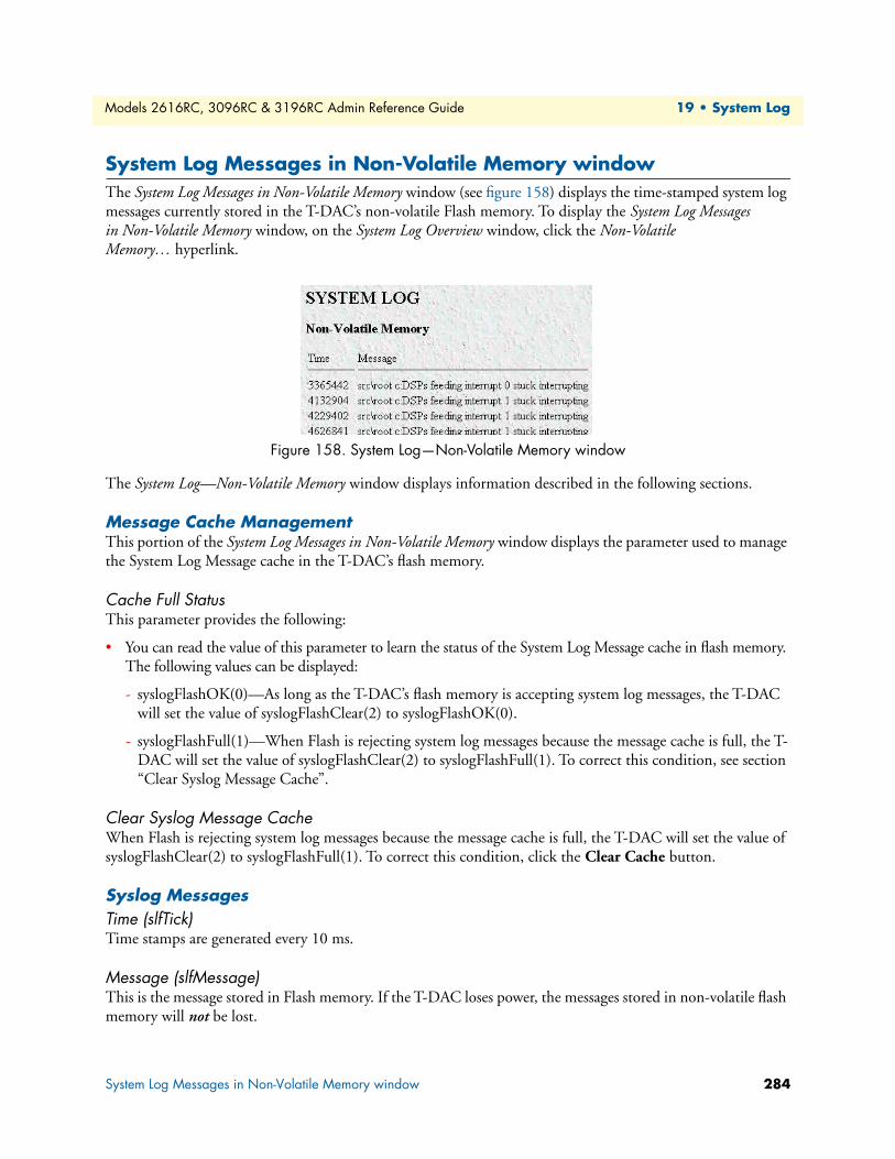
Models 2616RC, 3096RC & 3196RC Admin Reference Guide 19 • System Log
System Log Messages in Non-Volatile Memory windowThe System Log Messages in Non-Volatile Memory window (see figure 158) displays the time-stamped system log messages currently stored in the T-DAC’s non-volatile Flash memory. To display the System Log Messages in Non-Volatile Memory window, on the System Log Overview window, click the Non-Volatile Memory… hyperlink.
Figure 158. System Log—Non-Volatile Memory window
The System Log—Non-Volatile Memory window displays information described in the following sections.
Message Cache ManagementThis portion of the System Log Messages in Non-Volatile Memory window displays the parameter used to manage the System Log Message cache in the T-DAC’s flash memory.
Cache Full StatusThis parameter provides the following:
• You can read the value of this parameter to learn the status of the System Log Message cache in flash memory. The following values can be displayed:
- syslogFlashOK(0)—As long as the T-DAC’s flash memory is accepting system log messages, the T-DAC will set the value of syslogFlashClear(2) to syslogFlashOK(0).
- syslogFlashFull(1)—When Flash is rejecting system log messages because the message cache is full, the T-DAC will set the value of syslogFlashClear(2) to syslogFlashFull(1). To correct this condition, see section “Clear Syslog Message Cache”.
Clear Syslog Message CacheWhen Flash is rejecting system log messages because the message cache is full, the T-DAC will set the value of syslogFlashClear(2) to syslogFlashFull(1). To correct this condition, click the Clear Cache button.
Syslog MessagesTime (slfTick)Time stamps are generated every 10 ms.
Message (slfMessage)This is the message stored in Flash memory. If the T-DAC loses power, the messages stored in non-volatile flash memory will not be lost.
System Log Messages in Non-Volatile Memory window 284

Chapter 20 T1/E1 Link
Chapter contentsIntroduction ........................................................................................................................................................288T1/E1 Link Activity Ports window......................................................................................................................290
Link (dsx1LineIndex) ....................................................................................................................................291Type (dsx1LineType) ....................................................................................................................................291Circuit ID (dsx1CircuitIdentifier) .................................................................................................................291
Line Status (dsx1LineStatus)................................................................................................................................292Failure States .................................................................................................................................................292
Far end LOF or Yellow Alarm (Far End Alarm Failure) ..........................................................................292Near end or far end sending AIS (Alarm Indication Signal (AIS) Failure) ................................................293Near End LOF or Red Alarm (Loss of Frame Failure) .............................................................................293Near End Loss of Signal (Loss of Signal Failure) .....................................................................................293Near End is Looped (Loopback Pseudo-Failure) .....................................................................................293E1 TS16 AIS (TS16 Alarm Indication Signal Failure) .............................................................................293Far End Sending TS16 LOMF (Far End Loss of Multiframe Failure) .....................................................294Near End Sending TS16 LOMF (Loss of MultiFrame Failure) ...............................................................294Near End Detects a Test Code ................................................................................................................294Any Line Status not Defined Here ..........................................................................................................294Transmit Short ........................................................................................................................................294Transmit Open .......................................................................................................................................294
Line Status—Configuration.................................................................................................................................295Time Elapsed (dsx1TimeElapsed) .................................................................................................................295Valid Intervals (dsx1ValidIntervals) ...............................................................................................................296Receiver Quality ...........................................................................................................................................296
WAN Circuit Configuration—Modify................................................................................................................296
Line Interface Settings ...................................................................................................................................297Circuit ID (dsx1CircuitIdentifier) ...........................................................................................................297Line Type (dsx1LineType) ......................................................................................................................297Line Coding (dsx1LineCoding) ...............................................................................................................297Receive Equalizer (linkRxEqualizer) ........................................................................................................298Receiver Sensitivity (linkSensitivityLevel) ................................................................................................298Line Build Out (linkLineBuildOut) ........................................................................................................298Yellow Alarm Format (linkYellowFormat) ...............................................................................................298FDL (dsx1FDL) ......................................................................................................................................299
Test Settings .................................................................................................................................................299Force Yellow Alarm (linkYellowForce) ....................................................................................................299Loopback Configuration (dsx1LoopbackConfig) .....................................................................................299Send Code (dsx1SendCode) ....................................................................................................................299Error Injection (linkInjectError) ..............................................................................................................300Yellow Alarm Severity () ..........................................................................................................................300
285

Models 2616RC, 3096RC & 3196RC Admin Reference Guide 20 • T1/E1 Link
Red Alarm Severity () ..............................................................................................................................300WAN Circuit Configuration—Channel Assignment ...........................................................................................300Near End Line Statistics—Current ......................................................................................................................302
Errored Seconds (dsx1CurrentESs) ...............................................................................................................302Severely Errored Seconds (dsx1CurrentSESs) ................................................................................................302Severely Errored Frame Seconds (dsx1CurrentSEFSs) ...................................................................................302Unavailable Seconds (dsx1CurrentUASs) ......................................................................................................302Controlled Slip Seconds (dsx1CurrentCSSs) .................................................................................................302Path Code Violations (dsx1CurrentPCVs) ....................................................................................................302Line Errored Seconds (dsx1CurrentLESs) .....................................................................................................302Bursty ErroredSeconds (dsx1CurrentBESs) ...................................................................................................302Degraded Minutes (dsx1CurrentDMs) .........................................................................................................303Line Code Violations (dsx1CurrentLCVs) ....................................................................................................303
Near End Line Statistics—History.......................................................................................................................303Interval (dsx1IntervalNumber) ......................................................................................................................303Errored Seconds (dsx1intervaless) ..................................................................................................................303Severely Errored Seconds (dsx1IntervalSESs) ................................................................................................303Severely Errored Frame Seconds (dsx1IntervalSEFSs) ...................................................................................304Unavailable Seconds (dsx1IntervalUASs) ......................................................................................................304Controlled Slip Seconds (dsx1IntervalCSSs) .................................................................................................304Path Code Violations (dsx1IntervalPCVs) ....................................................................................................304Line Errored Seconds (dsx1IntervalLESs) ......................................................................................................304Bursty ErroredSeconds (dsx1IntervalBESs) ...................................................................................................304Degraded Minutes (dsx1IntervalDMs) ..........................................................................................................304Line Code Violations (dsx1IntervalLCVs) .....................................................................................................304
Near End Line Statistics—Totals.........................................................................................................................305Errored Seconds (dsx1TotalESs) ...................................................................................................................305Severely Errored Seconds (dsx1TotalSESs) ....................................................................................................305Severely Errored Frame Seconds (dsx1TotalSEFSs) .......................................................................................305Unavailable Seconds (dsx1TotalUASs) ..........................................................................................................305Controlled Slip Seconds (dsx1TotalCSSs) .....................................................................................................305Path Code Violations (dsx1TotalPCVs) ........................................................................................................305Line Errored Seconds (dsx1TotalLESs) .........................................................................................................305Bursty ErroredSeconds (dsx1TotalBESs) .......................................................................................................305Degraded Minutes (dsx1TotalDMs) .............................................................................................................306Line Code Violations (dsx1TotalLCVs) ........................................................................................................306
Far End Line Statistics—Current.........................................................................................................................306Time Elapsed (dsx1FarEndTimeElapsed) ......................................................................................................306Errored Seconds (dsx1FarEndCurrentESs) ....................................................................................................306Severely Errored Seconds (dsx1FarEnd CurrentSESs) ...................................................................................306Severely Errored Frame Seconds (dsx1FarEndCurrentSEFSs) .......................................................................306Unavailable Seconds (dsx1FarEndCurrentUASs) ..........................................................................................306Controlled Slip Seconds (dsx1FarEndCurrentCSSs) .....................................................................................306Line Errored Seconds (dsx1FarEndCurrentLESs) ..........................................................................................307
286
Models 2616RC, 3096RC & 3196RC Admin Reference Guide 20 • T1/E1 Link
Path Code Violations (dsx1FarEndCurrentPCVs) ........................................................................................307Bursty Errored Seconds (dsx1FarEndCurrentBESs) ......................................................................................307Degraded Minutes (dsx1FarEndCurrentDMs) ..............................................................................................307
Far End Line Statistics—History .........................................................................................................................307Interval (dsx1FarEndIntervalNumber) ..........................................................................................................307Errored Seconds (dsx1FarEndIntervalESs) ....................................................................................................308Severely Errored Seconds (dsx1FarEndIntervalSESs) .....................................................................................308Severely Errored Frame Seconds (dsx1FarEndIntervalSEFSs) ........................................................................308Unavailable Seconds (dsx1FarEndIntervalUASs) ...........................................................................................308Controlled Slip Seconds (dsx1FarEndIntervalCSSs) ......................................................................................308Line Errored Seconds (dsx1FarEndIntervalLESs) ..........................................................................................308Path Code Violations (dsx1FarEndIntervalPCVs) .........................................................................................308Bursty Errored Seconds (dsx1FarEndIntervalBESs) .......................................................................................308Degraded Minutes (dsx1FarEndIntervalDMs) ..............................................................................................308
Far End Line Statistics—Totals ...........................................................................................................................309Errored Seconds (dsx1FarEndTotalESs) ........................................................................................................309Severly Errored Seconds (dsx1FarEndTotalSESs) ..........................................................................................309Severely Errored Frame Seconds (dsx1FarEndTotalSEFSs) ...........................................................................309Unavailable Seconds (dsx1FarEndTotalUASs) ..............................................................................................309Controlled Slip Seconds (dsx1FarEndTotalCSSs) .........................................................................................309Line Errored Seconds (dsx1FarEndTotalLESs) ..............................................................................................309Path Code Violations (dsx1FarEndTotalPCVs) ............................................................................................309Bursty Errored Seconds (dsx1FarEndTotalBESs) ..........................................................................................310Degraded Minutes (dsx1FarEndTotalDMs) ..................................................................................................310
287
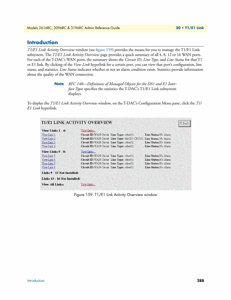
Models 2616RC, 3096RC & 3196RC Admin Reference Guide 20 • T1/E1 Link
IntroductionT1/E1 Link Activity Overview window (see figure 159) provides the means for you to manage the T1/E1 Link subsystem. The T1/E1 Link Activity Overview page provides a quick summary of all 4, 8, 12 or 16 WAN ports. For each of the T-DAC’s WAN ports, the summary shows the Circuit ID, Line Type, and Line Status for that T1 or E1 link. By clicking of the View Link hyperlink for a certain port, you can view that port’s configuration, line status, and statistics. Line Status indicates whether or not an alarm condition exists. Statistics provide information about the quality of the WAN connection.
Note RFC 140—Definitions of Managed Objects for the DS1 and E1 Inter-face Types specifies the statistics the T-DAC’s T1/E1 Link subsystem displays.
To display the T1/E1 Link Activity Overview window, on the T-DAC’s Configuration Menu pane, click the T1/E1 Link hyperlink.
Figure 159. T1/E1 Link Activity Overview window
Introduction 288

Models 2616RC, 3096RC & 3196RC Admin Reference Guide 20 • T1/E1 Link
The T1/E1 Link Activity Overview window provides links to the windows shown in figure 160.
Figure 160. T1/E1 Link Activity windows map
The T1/E1 Link Activity Overview main window contains the following items:
• View Links 1–4, View Links 5–8, View Links 9–12, and View Links 13–16. These links lead to windows that display supporting information on the WAN ports.
• View Links…. Clicking on these links display the T1/E1 Link Activity Ports windows which display Line Status, Near End Line Statistics, and Far End Line Statistics for each WAN port.
• The four groups have individual hyperlinks named View Link 1, View Link 2, … View Link 16 to windows named WAN Circuit Configuration Link: 1, … WAN Circuit Configuration Link: 16. Each of these win-dows displays the configuration settings for the T1/E1 port, the line status showing whether any alarms are present, hyperlinks to statistical data, and another hyperlink for modifying the configuration (Modify Configuration…).
T1/E1 LinkOverview
T1/E1 LinksSummary Status
T1/E1 LinksDetailed Status
T1/E1 ChannelDefinition
T1/E1 LinksConfiguration
T1/E1 LinksAlarms
T1/E1 Far-End LinkStatistics—Totals
T1/E1 Far-End LinkStatistics—History
T1/E1 Far-End LinkStatistics—Current
T1/E1 Near-End LinkStatistics—Totals
T1/E1 Near-End LinkStatistics—History
T1/E1 Near-End LinkStatistics—Current
Introduction 289
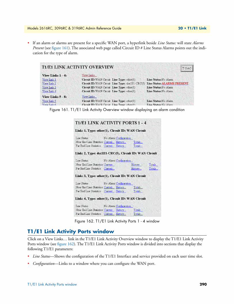
Models 2616RC, 3096RC & 3196RC Admin Reference Guide 20 • T1/E1 Link
• If an alarm or alarms are present for a specific WAN port, a hyperlink beside Line Status: will state Alarms Present (see figure 161). The associated web page called Circuit ID # Line Status Alarms points out the indi-cation for the type of alarm.
Figure 161. T1/E1 Link Activity Overview window displaying an alarm condition
Figure 162. T1/E1 Link Activity Ports 1 - 4 window
T1/E1 Link Activity Ports windowClick on a View Links… link in the T1/E1 Link Activity Overview window to display the T1/E1 Link Activity Ports window (see figure 162). The T1/E1 Link Activity Ports window is divided into sections that display the following T1/E1 parameters:
• Line Status—Shows the configuration of the T1/E1 Interface and service provided on each user time slot.
• Configuration—Links to a window where you can configure the WAN port.
T1/E1 Link Activity Ports window 290

Models 2616RC, 3096RC & 3196RC Admin Reference Guide 20 • T1/E1 Link
• Near End Line Statistics—Show error statistics collected from the near-end of the T1/E1 line.
• Far End Line Statistics—Show statistics collected from the far-end T1/E1 line. Far End Line Statistics can be used by devices that support the facility data link (FDL)
Link (dsx1LineIndex)This object identifies a DS1 Interface on a managed device. If there is an ifEntry directly associated with this DS1 interface, it must have the same value as ifIndex. Otherwise, the value exceeds ifNumber, and is assigned a unique identifier by following this rule: inside interfaces (equipment side) with even numbers and outside interfaces (net-work side) with odd numbers.
Type (dsx1LineType)This variable indicates the type of DS1 line using the circuit. The circuit type determines the bits-per-second rate that the circuit can carry and how it interprets error statistics. The values are as follows:
• Other(1)—Link is disabled
• dsx1ESF(2)—Extended Superframe DS1
• dsx1D4(3)—AT&T D4 format DS1
• dsx1E1(4)—Based on CCITT/ITU G.704 without CRC (Cyclical Redundancy Check)
• dsx1E1-CRC(5)—Based on CCITT/ITU G.704 with CRC (Cyclical Redundancy Check)
• dsx1E1-MF(6)—Based on CCIT/ITU G.704 without CRC (bit oriented signaling)
• dsx1E1-CRC-MF(7)—Based on CCIT/ITU G.704 with CRC (bit oriented signaling)
• dsx1E1-Transparent(8)—Based on CCIT/ITU G.703 without CRC (Cyclical Redundancy Check)
Circuit ID (dsx1CircuitIdentifier)This is the transmission vendor’s circuit identifier. Knowing the circuit ID can be helpful during troubleshooting.
T1/E1 Link Activity Ports window 291
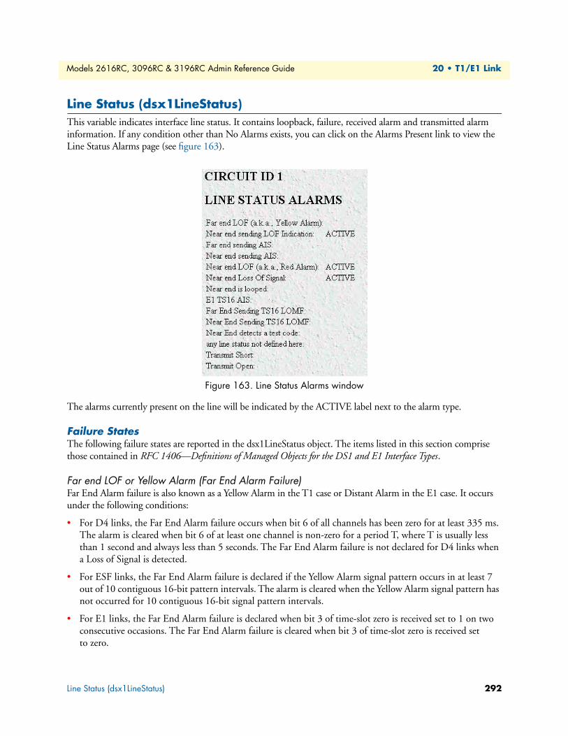
Models 2616RC, 3096RC & 3196RC Admin Reference Guide 20 • T1/E1 Link
Line Status (dsx1LineStatus)This variable indicates interface line status. It contains loopback, failure, received alarm and transmitted alarm information. If any condition other than No Alarms exists, you can click on the Alarms Present link to view the Line Status Alarms page (see figure 163).
Figure 163. Line Status Alarms window
The alarms currently present on the line will be indicated by the ACTIVE label next to the alarm type.
Failure StatesThe following failure states are reported in the dsx1LineStatus object. The items listed in this section comprise those contained in RFC 1406—Definitions of Managed Objects for the DS1 and E1 Interface Types.
Far end LOF or Yellow Alarm (Far End Alarm Failure)Far End Alarm failure is also known as a Yellow Alarm in the T1 case or Distant Alarm in the E1 case. It occurs under the following conditions:
• For D4 links, the Far End Alarm failure occurs when bit 6 of all channels has been zero for at least 335 ms. The alarm is cleared when bit 6 of at least one channel is non-zero for a period T, where T is usually less than 1 second and always less than 5 seconds. The Far End Alarm failure is not declared for D4 links when a Loss of Signal is detected.
• For ESF links, the Far End Alarm failure is declared if the Yellow Alarm signal pattern occurs in at least 7 out of 10 contiguous 16-bit pattern intervals. The alarm is cleared when the Yellow Alarm signal pattern has not occurred for 10 contiguous 16-bit signal pattern intervals.
• For E1 links, the Far End Alarm failure is declared when bit 3 of time-slot zero is received set to 1 on two consecutive occasions. The Far End Alarm failure is cleared when bit 3 of time-slot zero is received set to zero.
Line Status (dsx1LineStatus) 292

Models 2616RC, 3096RC & 3196RC Admin Reference Guide 20 • T1/E1 Link
Near end or far end sending AIS (Alarm Indication Signal (AIS) Failure)The Alarm Indication Signal failure is declared when an AIS defect is detected at the input and the AIS defect still exists after the Loss of Frame failure (which is caused by the unframed nature of the all-ones signal) is declared. The AIS failure is cleared when the Loss of Frame failure is cleared.
Near End LOF or Red Alarm (Loss of Frame Failure)Occurs under the following conditions:
• For T1 links, the Loss of Frame failure is declared when an OOF or LOS defect has persisted for T seconds, where 2 ≤ T ≤ 10. The Loss of Frame failure is cleared when there have been no OOF or LOS defects dur-ing a period T where 0 ≤ T ≤ 20. Many systems will perform hit integration within the period T before declaring or clearing the failure (for more information, see TR 62411 (16)).
• For E1 links, the Loss of Frame Failure is declared when an OOF defect is detected.
Near End Loss of Signal (Loss of Signal Failure)Occurs under the following conditions:
• For T1, the Loss of Signal failure is declared upon observing 175 ±75 contiguous pulse positions with no pulses of either positive or negative polarity. The LOS failure is cleared upon observing an average pulse density of at least 12.5% over a period of 175 ±75 contiguous pulse positions, starting with the receipt of a pulse.
• For E1 links, the Loss Of Signal failure is declared when greater than 10 consecutive zeroes are detected (see O.162 Section 3.4.4).
Near End is Looped (Loopback Pseudo-Failure)The Loopback Pseudo-Failure is declared when the near end equipment has placed a loopback (of any kind) on the DS1. This allows a management entity to determine from one object whether the DS1 can be considered to be in service or not (from the point of view of the near end equipment).
E1 TS16 AIS (TS16 Alarm Indication Signal Failure)For E1 links, the TS16 Alarm Indication Signal failure is declared when time-slot 16 is received as all ones for all frames of two consecutive multiframes (see G.732 Section 4.2.6). This condition is never declared for T1.
Line Status (dsx1LineStatus) 293

Models 2616RC, 3096RC & 3196RC Admin Reference Guide 20 • T1/E1 Link
Far End Sending TS16 LOMF (Far End Loss of Multiframe Failure)The Far End Loss of Multiframe failure is declared when bit 2 of TS16 of frame 0 is received set to one on two consecutive occasions. The Far End Loss of Multiframe failure is cleared when bit 2 of TS16 of frame 0 is received set to zero. The Far End Loss of Multiframe failure can only be declared for E1 links operating in Channel Associ-ated Signalling mode.
Near End Sending TS16 LOMF (Loss of MultiFrame Failure)The Loss Of MultiFrame failure is declared when two consecutive multiframe alignment signals (bits 4 through 7 of TS16 of frame 0) have been received with an error. The Loss of Multiframe failure is cleared when the first cor-rect multiframe alignment signal is received. The Loss of Multiframe failure can only be declared for E1 links operating with G.732 (18) framing (sometimes called Channel Associated Signaling mode).
Near End Detects a Test CodeThe Near End T1/E1 port has detected an incoming loop code. Upon detecting this loop code the T1/E1 port may enter a loop status. Any coming on the particular T1/E1 port will be transmitted back to the originator.
Any Line Status not Defined HereThe T1/E1 port has detected a condition on the line that is not defined in any of the failure modes listed on this screen.
Transmit ShortAn internal condition detected by the T1/E1 transceiver—useful for technical personnel while troubleshooting at the board level.
Transmit OpenAn internal condition detected by the T1/E1 transceiver—useful for technical personnel while troubleshooting at the board level.
Line Status (dsx1LineStatus) 294

Models 2616RC, 3096RC & 3196RC Admin Reference Guide 20 • T1/E1 Link
Line Status—ConfigurationClicking on the Line Status—Configuration hyperlink in the T1/E1 Link Activity Ports page displays the WAN Circuit Configuration hyperlink page (see figure 164). This page contains general information about the WAN interface, including the type of line (D4 Superframe or Extended Superframe), type of line coding (B8ZS or AMI), Near and Far End Line Statistics, and Line Status. On this page, is the ability to modify the Line Interface Settings and Test Settings by clicking on the Modify Configuration link as well as modifying the channel assign-ments by clicking on the Channel Assignments link. Also on this page is the ability to retrieve both Near and Far End Line Statistics by clicking on Current, History, or Totals.
Figure 164. WAN Circuit Configuration Link window
Note Click on the Modify link to change the settings of any of the follow-ing parameters (see “WAN Circuit Configuration—Modify” on page 296).
The WAN Circuit Configuration window also displays the amount of time that has passed, the number of inter-vals passed during which valid data was collected, and a measurement of received signal quality.
Time Elapsed (dsx1TimeElapsed)The number of seconds that have elapsed since the beginning of the current error-measurement period.
Line Status—Configuration 295
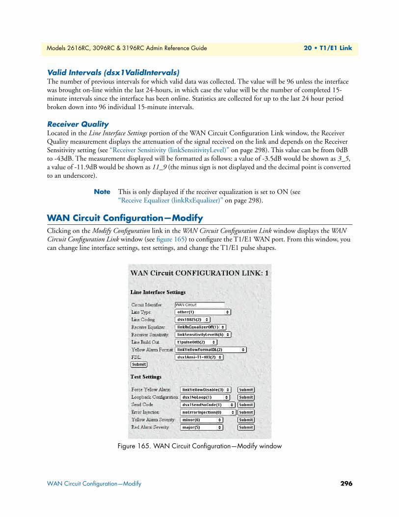
Models 2616RC, 3096RC & 3196RC Admin Reference Guide 20 • T1/E1 Link
Valid Intervals (dsx1ValidIntervals)The number of previous intervals for which valid data was collected. The value will be 96 unless the interface was brought on-line within the last 24-hours, in which case the value will be the number of completed 15-minute intervals since the interface has been online. Statistics are collected for up to the last 24 hour period broken down into 96 individual 15-minute intervals.
Receiver QualityLocated in the Line Interface Settings portion of the WAN Circuit Configuration Link window, the Receiver Quality measurement displays the attenuation of the signal received on the link and depends on the Receiver Sensitivity setting (see “Receiver Sensitivity (linkSensitivityLevel)” on page 298). This value can be from 0dB to -43dB. The measurement displayed will be formatted as follows: a value of -3.5dB would be shown as 3_5, a value of -11.9dB would be shown as 11_9 (the minus sign is not displayed and the decimal point is converted to an underscore).
Note This is only displayed if the receiver equalization is set to ON (see “Receive Equalizer (linkRxEqualizer)” on page 298).
WAN Circuit Configuration—ModifyClicking on the Modify Configuration link in the WAN Circuit Configuration Link window displays the WAN Circuit Configuration Link window (see figure 165) to configure the T1/E1 WAN port. From this window, you can change line interface settings, test settings, and change the T1/E1 pulse shapes.
Figure 165. WAN Circuit Configuration—Modify window
WAN Circuit Configuration—Modify 296
Models 2616RC, 3096RC & 3196RC Admin Reference Guide 20 • T1/E1 Link
Line Interface SettingsThis portion of the WAN Circuit Configuration window contains information described in the following sections.
Circuit ID (dsx1CircuitIdentifier)This variable contains the transmission vendor’s circuit identifier, for the purpose of facilitating troubleshooting.
Line Type (dsx1LineType)This variable indicates the type of DS1 Line implemented on this circuit. The type of circuit affects the num-ber of bits per second that the circuit can reasonably carry, as well as the interpretation of the usage and error statistics. The values, in sequence, are:
• other(1)—Link is disabled
• dsx1ESF(2)—Extended Superframe DS1
• dsx1D4(3)—AT&T D4 format DS1
• dsx1E1(4)—Based on CCITT/ITU G.704 without CRC (Cyclical Redundancy Check)
• dsx1E1-CRC(5)—Based on CCITT/ITU G.704 with CRC (Cyclical Redundancy Check)
• dsx1E1-MF(6)—Based on CCIT/ITU G.704 without CRC (bit oriented signaling)
• dsx1E1-CRC-MF(7)—Based on CCIT/ITU G.704 with CRC (bit oriented signaling)
• dsx1E1-Transparent(8)—Based on CCIT/ITU G.703 without CRC (Cyclical Redundancy Check)
Line Coding (dsx1LineCoding)This variable describes the type of Zero Code Suppression used on the link, which in turn affects a number of its characteristics.
• dsx1JBZS(1)—Jammed Bit Zero Suppression, in which the AT&T specification of at least one pulse every 8 bit periods is literally implemented by forcing a pulse in bit 8 of each channel. Thus, only seven bits per channel, or 1.344 Mbps, is available for data. This feature is not currently implemented.
• dsx1B8ZS(2)—The use of a specified pattern of normal bits and bipolar violations which are used to replace a sequence of eight zero bits. The most common coding for T1 circuits.
• dsx1HDB3(3)—This line coding is used with most E1 circuits today.
• dsx1ZBTSI(4)—May use dsx1ZBTSI, or Zero Byte Time Slot Interchange. This feature is not currently implemented.
• dsx1AMI(5)—Refers to a mode wherein no zero code suppression is present and the line encoding does not solve the problem directly. In this application, the higher layer must provide data which meets or exceeds the pulse density requirements, such as inverting HDLC data.
• other(6)—This feature is not currently supported.
WAN Circuit Configuration—Modify 297

Models 2616RC, 3096RC & 3196RC Admin Reference Guide 20 • T1/E1 Link
Receive Equalizer (linkRxEqualizer)This variable determines the equalization used on the received signal. Long haul signals should have the equal-ization set for more. Short haul signals require less equalization.
• linkRxEqualizerOff(1)
• linkRxEqualizerOn(2)
Receiver Sensitivity (linkSensitivityLevel)This variable selects the minimum voltage at which the WAN port will sense that the signal is available. The default setting is linkSensitivityLevel5.
Note This variable is only used if the receiver equalization is set to ON (see “Receive Equalizer (linkRxEqualizer)” on page 298).
• linkSensitivityLevel1(1)—Voltage threshold: 1.70V; maximum distance achievable: less than 1,000 feet (305 meters)
• linkSensitivityLevel2(2)—Voltage threshold: 0.84V; maximum distance achievable: less than 2,000 feet (610 meters)
• linkSensitivityLevel3(3)—Voltage threshold: 0.84V; maximum distance achievable: less than 3,000 feet (914 meters)
• linkSensitivityLevel4(4)—Voltage threshold: 0.45V; maximum distance achievable: less than 5,000 feet (1,524 meters)
• linkSensitivityLevel5(5)—Voltage threshold: 0.45V; maximum distance achievable: less than 5,000 feet (1,524 meters)
• linkSensitivityLevel6(6)—Voltage threshold: 0.2V; maximum distance achievable: less than 5,000 feet (1,524 meters)
• linkSensitivityLevel7(7)—Voltage threshold: 0.1V; maximum distance achievable: less than 5,000 feet (1,524 meters)
Line Build Out (linkLineBuildOut)This variable defines the T1 or E1 pulse levels used by the T1/E1 ports:
• triState(0)—When the T1/E1 port is not in use, the user may want to place the port in tri-state mode. While in this setting, the input lines to the port are placed in high impedance protection mode.
• e1pulse(1)—Used when connecting the T1/E1 port to E1 lines.
• t1pulse0dB(2)—Strong T1 pulse amplitude.
• t1pulse-7dB(3)—Medium T1 pulse amplitude.
• t1pulse-15dB(4)—Weak T1 pulse amplitude.
Yellow Alarm Format (linkYellowFormat)This variable identifies which standard will be used to transmit and identify the Yellow Alarm.
• link YellowFormatBit2(1)—Bit-2 equal zero in every channel
WAN Circuit Configuration—Modify 298
Models 2616RC, 3096RC & 3196RC Admin Reference Guide 20 • T1/E1 Link
• YellowFormatDL(2)—FF00 pattern in the Data Link
• YellowFormatFrame12FS(3)—FS bit of frame 12
FDL (dsx1FDL)This variable describes which implementation of FDL is being used, if any. FDL applies only to T1 circuits.
• other(1)—Indicates that a protocol other than one following is used.
• dsx1Ansi-T1-403(2)—Refers to the FDL exchange recommended by ANSI.
• dsx1Att-54016(3)—Refers to ESF FDL exchanges.
• dsx1Fdl-none(4)—Indicates that the device does not use the FDL.
If one of the E1 line types has been selected, this parameter is ignored.
Test SettingsThis portion of the WAN Circuit Configuration Link window contains information described in the following sections.
Force Yellow Alarm (linkYellowForce)This variable identifies which standard will be used to transmit and identify the Yellow Alarm.
• linkYellowAuto—Do not force the transmission of a yellow alarm. But, yellow alarm may be automatically transmitted.
• linkYellowOn—Force the transmission of a yellow alarm even if the received signal is in frame.
• linkYellowDisable—Do NOT transmit a yellow alarm even if the received signal is out of frame.
Loopback Configuration (dsx1LoopbackConfig)This variable represents the loopback configuration of the DS1 interface. Agents supporting read/write access should return badValue in response to a requested loopback state that the interface does not support. The val-ues mean:
• dsx1NoLoop(1)—Not in the loopback state. A device that is not capable of performing a loopback on the interface shall always return this as it's value.
• dsx1PayloadLoop(2)—The received signal at this interface is looped through the device. Typically the received signal is looped back for retransmission after it has passed through the device's framing function.
• dsx1LineLoop(3)—The received signal at this interface does not go through the device (minimum penetra-tion) but is looped back out.
• dsx1OtherLoop(4)—Loopbacks that are not defined here.
Send Code (dsx1SendCode)• This variable indicates what type of code is being sent across the DS1 interface by the device. The
values mean:
• dsx1SendNoCode(1)—Sending looped or normal data
• dsx1SendLineCode(2)—Sending a request for a line loopback
WAN Circuit Configuration—Modify 299

Models 2616RC, 3096RC & 3196RC Admin Reference Guide 20 • T1/E1 Link
• dsx1SendResetCode(4)—Sending a loopback termination request
Error Injection (linkInjectError)Force an output error to see if the other end detects it
• noErrorInjection(0)
• injectCRCerrorBurst(1)
• injectLineErrorBurst(2)
Yellow Alarm Severity ()This reference is identical to the reference on the Alarms window in the Configuration Menu. The configura-tion may be changed here or in the Alarms window.
• critical(4)
• major(5)
• minor(6)
• informational(7)
• ignore(8)
Red Alarm Severity ()This reference is identical to the reference on the Alarms page in the Configuration Menu. The configuration may be changed here or in the Alarms page.
• critical(4)
• major(5)
• minor(6)
• informational(7)
• ignore(8)
WAN Circuit Configuration—Channel AssignmentFor each T1/E1 link, the DS0s can provide two functions:
• Carrying TDM user data
• Carrying in-band management information
By factory default, the T-DAC allocates all DS0s to carry TDM user data. The WAN Circuit Channel Assign-ment window provides the means for you to allocate DS0s on a selected T1 or E1 WAN link to be used for in-band management of the T-DAC.
You can use the WAN Circuit Channel Assignment window to change selected DS0 channels to carry in-band management information over Frame Relay or PPP links. You can use the buttons at the top of the window to modify all 30 timeslots at once. Or you can use the 30 drop-down menus to modify selected timeslots individually.
WAN Circuit Configuration—Channel Assignment 300

Models 2616RC, 3096RC & 3196RC Admin Reference Guide 20 • T1/E1 Link
To display the WAN Circuit Channel Assignment window:
• Determine which T1/E1 WAN circuit you wish to use for in-band management
• Display the WAN Circuit Configuration Link page for your selected T1/E1 link
• Click the Channel Assignment hyperlink
Note After modifying the channel assignments, click Submit Query to make activate the changes.
Figure 166. WAN Circuit CHANNEL ASSIGNMENT window
WAN Circuit Configuration—Channel Assignment 301
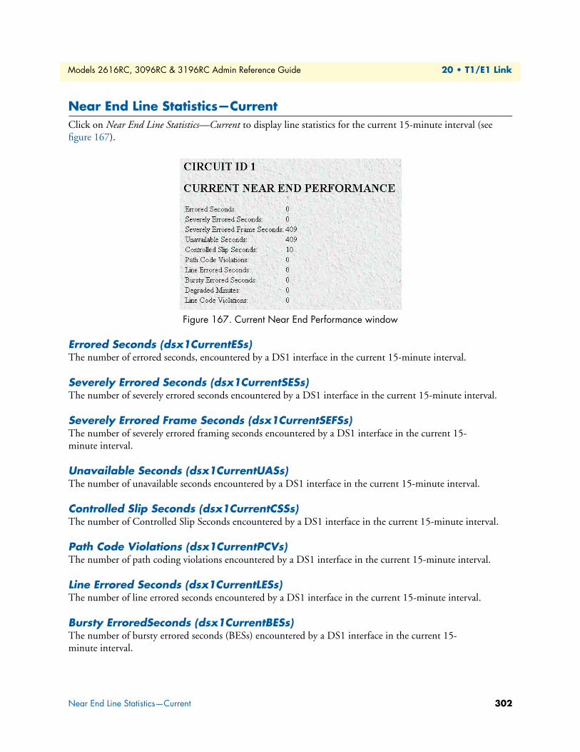
Models 2616RC, 3096RC & 3196RC Admin Reference Guide 20 • T1/E1 Link
Near End Line Statistics—CurrentClick on Near End Line Statistics—Current to display line statistics for the current 15-minute interval (see figure 167).
Figure 167. Current Near End Performance window
Errored Seconds (dsx1CurrentESs)The number of errored seconds, encountered by a DS1 interface in the current 15-minute interval.
Severely Errored Seconds (dsx1CurrentSESs)The number of severely errored seconds encountered by a DS1 interface in the current 15-minute interval.
Severely Errored Frame Seconds (dsx1CurrentSEFSs)The number of severely errored framing seconds encountered by a DS1 interface in the current 15-minute interval.
Unavailable Seconds (dsx1CurrentUASs)The number of unavailable seconds encountered by a DS1 interface in the current 15-minute interval.
Controlled Slip Seconds (dsx1CurrentCSSs)The number of Controlled Slip Seconds encountered by a DS1 interface in the current 15-minute interval.
Path Code Violations (dsx1CurrentPCVs)The number of path coding violations encountered by a DS1 interface in the current 15-minute interval.
Line Errored Seconds (dsx1CurrentLESs)The number of line errored seconds encountered by a DS1 interface in the current 15-minute interval.
Bursty ErroredSeconds (dsx1CurrentBESs)The number of bursty errored seconds (BESs) encountered by a DS1 interface in the current 15-minute interval.
Near End Line Statistics—Current 302
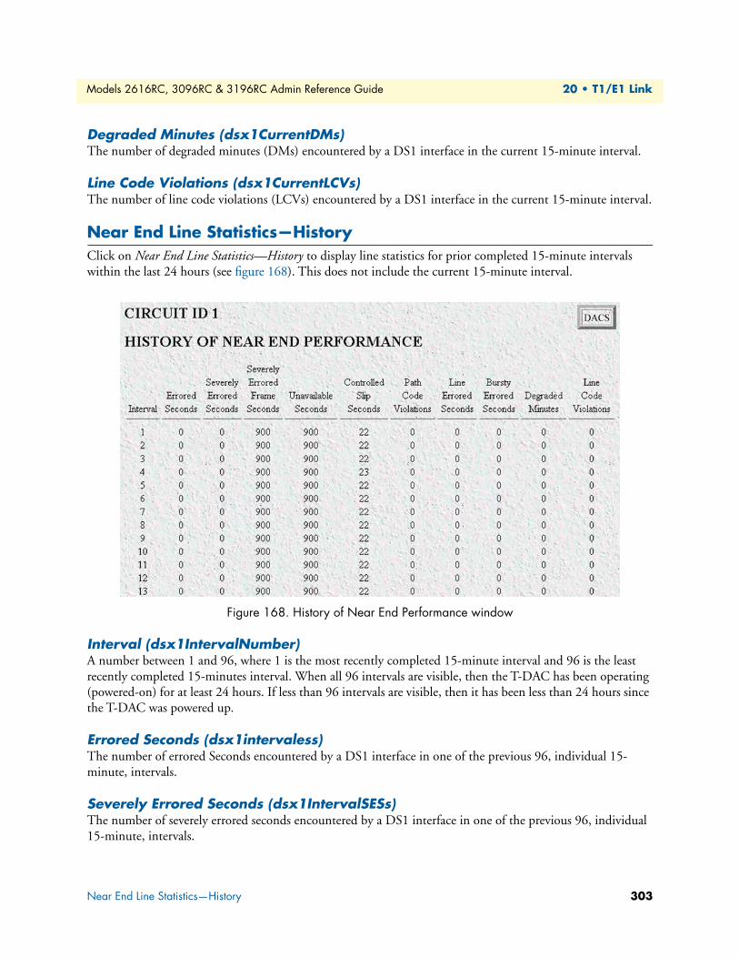
Models 2616RC, 3096RC & 3196RC Admin Reference Guide 20 • T1/E1 Link
Degraded Minutes (dsx1CurrentDMs)The number of degraded minutes (DMs) encountered by a DS1 interface in the current 15-minute interval.
Line Code Violations (dsx1CurrentLCVs)The number of line code violations (LCVs) encountered by a DS1 interface in the current 15-minute interval.
Near End Line Statistics—HistoryClick on Near End Line Statistics—History to display line statistics for prior completed 15-minute intervals within the last 24 hours (see figure 168). This does not include the current 15-minute interval.
Figure 168. History of Near End Performance window
Interval (dsx1IntervalNumber)A number between 1 and 96, where 1 is the most recently completed 15-minute interval and 96 is the least recently completed 15-minutes interval. When all 96 intervals are visible, then the T-DAC has been operating (powered-on) for at least 24 hours. If less than 96 intervals are visible, then it has been less than 24 hours since the T-DAC was powered up.
Errored Seconds (dsx1intervaless)The number of errored Seconds encountered by a DS1 interface in one of the previous 96, individual 15-minute, intervals.
Severely Errored Seconds (dsx1IntervalSESs)The number of severely errored seconds encountered by a DS1 interface in one of the previous 96, individual 15-minute, intervals.
Near End Line Statistics—History 303
Models 2616RC, 3096RC & 3196RC Admin Reference Guide 20 • T1/E1 Link
Severely Errored Frame Seconds (dsx1IntervalSEFSs)The number of severely errored framing seconds encountered by a DS1 interface in one of the previous 96, individual 15-minute, intervals.
Unavailable Seconds (dsx1IntervalUASs)The number of unavailable seconds encountered by a DS1 interface in one of the previous 96, individual 15-minute, intervals.
Controlled Slip Seconds (dsx1IntervalCSSs)The number of controlled slip seconds encountered by a DS1 interface in one of the previous 96, individual 15-minute, intervals.
Path Code Violations (dsx1IntervalPCVs)The number of path coding violations encountered by a DS1 interface in one of the previous 96, individual 15-minute, intervals.
Line Errored Seconds (dsx1IntervalLESs)The number of line errored seconds encountered by a DS1 interface in one of the previous 96, individual 15-minute, intervals.
Bursty ErroredSeconds (dsx1IntervalBESs)The number of bursty errored seconds (BESs) encountered by a DS1 interface in one of the previous 96, indi-vidual 15-minute, intervals.
Degraded Minutes (dsx1IntervalDMs)The number of degraded minutes (DMs) encountered by a DS1 interface in one of the previous 96, individual 15-minute, intervals.
Line Code Violations (dsx1IntervalLCVs)The number of line code violations (LCVs) encountered by a DS1 interface in the current 15-minute interval.
Near End Line Statistics—History 304
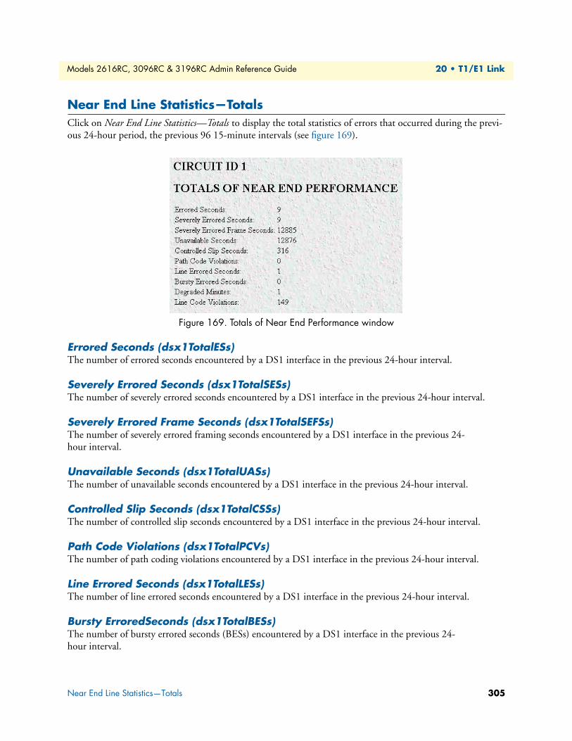
Models 2616RC, 3096RC & 3196RC Admin Reference Guide 20 • T1/E1 Link
Near End Line Statistics—TotalsClick on Near End Line Statistics—Totals to display the total statistics of errors that occurred during the previ-ous 24-hour period, the previous 96 15-minute intervals (see figure 169).
Figure 169. Totals of Near End Performance window
Errored Seconds (dsx1TotalESs)The number of errored seconds encountered by a DS1 interface in the previous 24-hour interval.
Severely Errored Seconds (dsx1TotalSESs)The number of severely errored seconds encountered by a DS1 interface in the previous 24-hour interval.
Severely Errored Frame Seconds (dsx1TotalSEFSs)The number of severely errored framing seconds encountered by a DS1 interface in the previous 24-hour interval.
Unavailable Seconds (dsx1TotalUASs)The number of unavailable seconds encountered by a DS1 interface in the previous 24-hour interval.
Controlled Slip Seconds (dsx1TotalCSSs)The number of controlled slip seconds encountered by a DS1 interface in the previous 24-hour interval.
Path Code Violations (dsx1TotalPCVs)The number of path coding violations encountered by a DS1 interface in the previous 24-hour interval.
Line Errored Seconds (dsx1TotalLESs)The number of line errored seconds encountered by a DS1 interface in the previous 24-hour interval.
Bursty ErroredSeconds (dsx1TotalBESs)The number of bursty errored seconds (BESs) encountered by a DS1 interface in the previous 24-hour interval.
Near End Line Statistics—Totals 305
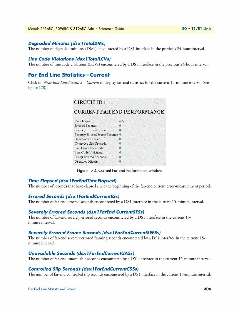
Models 2616RC, 3096RC & 3196RC Admin Reference Guide 20 • T1/E1 Link
Degraded Minutes (dsx1TotalDMs)The number of degraded minutes (DMs) encountered by a DS1 interface in the previous 24-hour interval.
Line Code Violations (dsx1TotalLCVs)The number of line code violations (LCVs) encountered by a DS1 interface in the previous 24-hour interval.
Far End Line Statistics—CurrentClick on Near End Line Statistics—Current to display far-end statistics for the current 15-minute interval (see figure 170).
Figure 170. Current Far End Performance window
Time Elapsed (dsx1FarEndTimeElapsed)The number of seconds that have elapsed since the beginning of the far-end current error-measurement period.
Errored Seconds (dsx1FarEndCurrentESs)The number of far-end errored seconds encountered by a DS1 interface in the current 15-minute interval.
Severely Errored Seconds (dsx1FarEnd CurrentSESs)The number of far-end severely errored seconds encountered by a DS1 interface in the current 15-minute interval.
Severely Errored Frame Seconds (dsx1FarEndCurrentSEFSs)The number of far-end severely errored framing seconds encountered by a DS1 interface in the current 15-minute interval.
Unavailable Seconds (dsx1FarEndCurrentUASs)The number of far-end unavailable seconds encountered by a DS1 interface in the current 15-minute interval.
Controlled Slip Seconds (dsx1FarEndCurrentCSSs)The number of far-end controlled slip seconds encountered by a DS1 interface in the current 15-minute interval.
Far End Line Statistics—Current 306
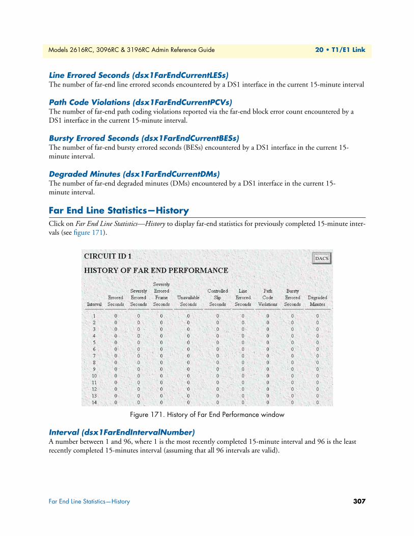
Models 2616RC, 3096RC & 3196RC Admin Reference Guide 20 • T1/E1 Link
Line Errored Seconds (dsx1FarEndCurrentLESs)The number of far-end line errored seconds encountered by a DS1 interface in the current 15-minute interval
Path Code Violations (dsx1FarEndCurrentPCVs)The number of far-end path coding violations reported via the far-end block error count encountered by a DS1 interface in the current 15-minute interval.
Bursty Errored Seconds (dsx1FarEndCurrentBESs)The number of far-end bursty errored seconds (BESs) encountered by a DS1 interface in the current 15-minute interval.
Degraded Minutes (dsx1FarEndCurrentDMs)The number of far-end degraded minutes (DMs) encountered by a DS1 interface in the current 15-minute interval.
Far End Line Statistics—HistoryClick on Far End Line Statistics—History to display far-end statistics for previously completed 15-minute inter-vals (see figure 171).
Figure 171. History of Far End Performance window
Interval (dsx1FarEndIntervalNumber)A number between 1 and 96, where 1 is the most recently completed 15-minute interval and 96 is the least recently completed 15-minutes interval (assuming that all 96 intervals are valid).
Far End Line Statistics—History 307
Models 2616RC, 3096RC & 3196RC Admin Reference Guide 20 • T1/E1 Link
Errored Seconds (dsx1FarEndIntervalESs)The number of far-end errored seconds encountered by a DS1 interface in one of the previous 96, individual 15-minute, intervals.
Severely Errored Seconds (dsx1FarEndIntervalSESs)The number of far-end severely errored seconds encountered by a DS1 interface in one of the previous 96, individual 15-minute, intervals.
Severely Errored Frame Seconds (dsx1FarEndIntervalSEFSs)The number of far-end severely errored framing seconds encountered by a DS1 interface in one of the previous 96, individual 15-minute, intervals.
Unavailable Seconds (dsx1FarEndIntervalUASs)The number of far-end unavailable seconds encountered by a DS1 interface in one of the previous 96, individ-ual 15-minute, intervals.
Controlled Slip Seconds (dsx1FarEndIntervalCSSs)The number of far-end controlled slip seconds encountered by a DS1 interface in one of the previous 96, indi-vidual 15-minute, intervals.
Line Errored Seconds (dsx1FarEndIntervalLESs)The number of far-end line errored seconds encountered by a DS1 interface in one of the previous 96, individ-ual 15-minute, intervals.
Path Code Violations (dsx1FarEndIntervalPCVs)The number of far-end path coding violations encountered by a DS1 interface in one of the previous 96, indi-vidual 15-minute, intervals.
Bursty Errored Seconds (dsx1FarEndIntervalBESs)The number of far-end bursty errored seconds (BESs) encountered by a DS1 interface in one of the previous 96, individual 15-minute, intervals.
Degraded Minutes (dsx1FarEndIntervalDMs)The number of far-end degraded minutes (DMs) encountered by a DS1 interface in one of the previous 96, individual 15-minute, intervals.
Far End Line Statistics—History 308
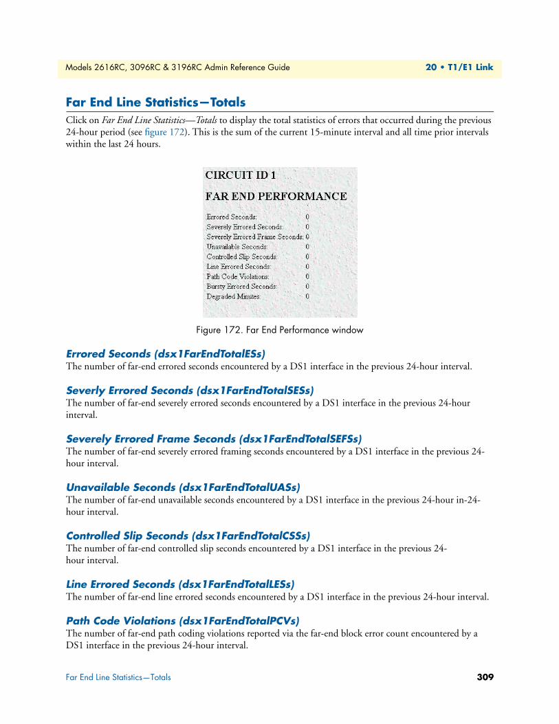
Models 2616RC, 3096RC & 3196RC Admin Reference Guide 20 • T1/E1 Link
Far End Line Statistics—TotalsClick on Far End Line Statistics—Totals to display the total statistics of errors that occurred during the previous 24-hour period (see figure 172). This is the sum of the current 15-minute interval and all time prior intervals within the last 24 hours.
Figure 172. Far End Performance window
Errored Seconds (dsx1FarEndTotalESs)The number of far-end errored seconds encountered by a DS1 interface in the previous 24-hour interval.
Severly Errored Seconds (dsx1FarEndTotalSESs)The number of far-end severely errored seconds encountered by a DS1 interface in the previous 24-hour interval.
Severely Errored Frame Seconds (dsx1FarEndTotalSEFSs)The number of far-end severely errored framing seconds encountered by a DS1 interface in the previous 24-hour interval.
Unavailable Seconds (dsx1FarEndTotalUASs)The number of far-end unavailable seconds encountered by a DS1 interface in the previous 24-hour in-24-hour interval.
Controlled Slip Seconds (dsx1FarEndTotalCSSs)The number of far-end controlled slip seconds encountered by a DS1 interface in the previous 24-hour interval.
Line Errored Seconds (dsx1FarEndTotalLESs)The number of far-end line errored seconds encountered by a DS1 interface in the previous 24-hour interval.
Path Code Violations (dsx1FarEndTotalPCVs)The number of far-end path coding violations reported via the far-end block error count encountered by a DS1 interface in the previous 24-hour interval.
Far End Line Statistics—Totals 309
Models 2616RC, 3096RC & 3196RC Admin Reference Guide 20 • T1/E1 Link
Bursty Errored Seconds (dsx1FarEndTotalBESs)The number of far-end bursty errored seconds (BESs) encountered by a DS1 interface in the previous 24-hour interval.
Degraded Minutes (dsx1FarEndTotalDMs)The number of far-end degraded minutes (DMs) encountered by a DS1 interface in the previous 24-hour interval.
Far End Line Statistics—Totals 310

Chapter 21 About
Chapter contentsIntroduction ........................................................................................................................................................312Patton Electronics Company contact information ...............................................................................................312
311

Models 2616RC, 3096RC & 3196RC Admin Reference Guide 21 • About
IntroductionThe About link displays Patton Electronics Company contact information (see “Patton Electronics Company contact information”). Click on About under the T-DAC’s Configuration Menu to display the About main win-dow (see figure 173).
Figure 173. About window
Patton Electronics Company contact informationPatton Electronics Company7622 Rickenbacker DriveGaithersburg, Maryland 20879U.S.A.
Phone: +1 (301) 975-1000
Fax: +1 (301) 869-9293
E-mail: [email protected]@patton.com
WWW: www.patton.com
Introduction 312
Chapter 22 License
Chapter contentsIntroduction ........................................................................................................................................................314End User License Agreement ...............................................................................................................................314
1. Definitions: ...............................................................................................................................................3142. Title: .........................................................................................................................................................3143. Term: ........................................................................................................................................................3144. Grant of License: .......................................................................................................................................3155. Warranty: .................................................................................................................................................3156. Termination: .............................................................................................................................................315
313
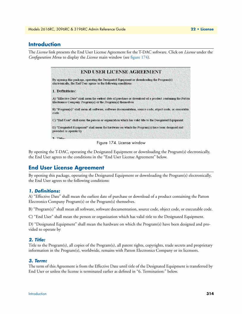
Models 2616RC, 3096RC & 3196RC Admin Reference Guide 22 • License
IntroductionThe License link presents the End User License Agreement for the T-DAC software. Click on License under the Configuration Menu to display the License main window (see figure 174).
Figure 174. License window
By opening the T-DAC, operating the Designated Equipment or downloading the Program(s) electronically, the End User agrees to the conditions in the “End User License Agreement” below.
End User License AgreementBy opening this package, operating the Designated Equipment or downloading the Program(s) electronically, the End User agrees to the following conditions:
1. Definitions:A) “Effective Date” shall mean the earliest date of purchase or download of a product containing the Patton Electronics Company Program(s) or the Program(s) themselves.
B) “Program(s)” shall mean all software, software documentation, source code, object code, or executable code.
C) “End User” shall mean the person or organization which has valid title to the Designated Equipment.
D) “Designated Equipment” shall mean the hardware on which the Program(s) have been designed and pro-vided to operate by
2. Title:Title to the Program(s), all copies of the Program(s), all patent rights, copyrights, trade secrets and proprietary information in the Program(s), worldwide, remains with Patton Electronics Company or its licensors.
3. Term:The term of this Agreement is from the Effective Date until title of the Designated Equipment is transferred by End User or unless the license is terminated earlier as defined in “6. Termination:” below.
Introduction 314
Models 2616RC, 3096RC & 3196RC Admin Reference Guide 22 • License
4. Grant of License:A) During the term of this Agreement, Patton Electronics Company grants a personal, non-transferable, non-assignable and non-exclusive license to the End User to use the Program(s) only with the Designated Equip-ment at a site owned or leased by the End User.
B) The End User may copy licensed Program(s) as necessary for backup purposes only for use with the Desig-nated Equipment that was first purchased or used or its temporary or permanent replacement.
C) The End User is prohibited from disassembling; decompiling, reverse-engineering or otherwise attempting to discover or disclose the Program(s), source code, methods or concepts embodied in the Program(s) or having the same done by another party.
D) Should End User transfer title of the Designated Equipment to a third party after entering into this license agreement, End User is obligated to inform the third party in writing that a separate End User License Agree-ment from Patton Electronics Company is required to operate the Designated Equipment.
5. Warranty:The Program(s) are provided “as is” without warranty of any kind. Patton Electronics Company and its licen-sors disclaim all warranties, either express or implied, including but not limited to the implied warranties of merchantability, fitness for a particular purpose or non-infringement. In no event shall Patton Electronics Company or its licensors be liable for any damages whatsoever (including, without limitation, damages for loss of business profits, business interruption, loss of business information, or other pecuniary loss) arising out of the use of or inability to use the Program(s), even if Patton Electronics Company has been advised of the possi-bility of such damages. Because some states do not allow the exclusion or limitation of liability for consequen-tial or incidental damages, the above limitation may not apply to you.
If the Program(s) are acquired by or on behalf of a unit or agency of the United States Government, the Gov-ernment agrees that such Program(s) are “commercial computer software” or “computer software documenta-tion” and that, absent a written agreement to the contrary, the Government’s rights with respect to such Program(s) are limited by the terms of this Agreement, pursuant to Federal Acquisition Regulations 12.212(a) and/or DEARS 227.7202-1(a) and/or sub-paragraphs (a) through (d) of the “Commercial Computer Soft-ware—Restricted Rights” clause at 48 C.F.R. 52.227-19 of the Federal Acquisition Regulations as applicable.
6. Termination:A) The End User may terminate this agreement by returning the Designated Equipment and destroying all copies of the licensed Program(s).
B) Patton Electronics Company may terminate this Agreement should End User violate any of the provisions of “4. Grant of License:” above.
C) Upon termination for A or B above or the end of the Term, End User is required to destroy all copies of the licensed Program(s)
End User License Agreement 315