Embed Size (px)
Citation preview

Schneider Electric Brands
Model 6 Export Motor Control Centers
Class 8998
CONTENTS
Description PageProduct Description . . . . . . . . . . . . . . . . . . . . . . . . . . . . . . . . . . . . . . . . . . . . . . . . . . 3Technical Overview . . . . . . . . . . . . . . . . . . . . . . . . . . . . . . . . . . . . . . . . . . . . . . . . . . 17Application and General Information. . . . . . . . . . . . . . . . . . . . . . . . . . . . . . . . . . . . . 19Dimensions . . . . . . . . . . . . . . . . . . . . . . . . . . . . . . . . . . . . . . . . . . . . . . . . . . . . . . . . 51Sample Specifications. . . . . . . . . . . . . . . . . . . . . . . . . . . . . . . . . . . . . . . . . . . . . . . . 79Appendix . . . . . . . . . . . . . . . . . . . . . . . . . . . . . . . . . . . . . . . . . . . . . . . . . . . . . . . . . . 87


Model 6 Export Motor Control CentersProduct Description
07/01
SECTION CONTENTS
SECTION 1—PRODUCT DESCRIPTION . . . . . . . . . . . . . . . . . . . . . . . . . . . . . . . . . . . . . . . . . . . . . . 4Introduction . . . . . . . . . . . . . . . . . . . . . . . . . . . . . . . . . . . . . . . . . . . . . . . . . . . . . . . . . . . . . . . . . . 4
Structural Features . . . . . . . . . . . . . . . . . . . . . . . . . . . . . . . . . . . . . . . . . . . . . . . . . . . . . . . . . . . . 6Functional (Outgoing) Unit Features . . . . . . . . . . . . . . . . . . . . . . . . . . . . . . . . . . . . . . . . . . . . . . . 8Bus Bar Features . . . . . . . . . . . . . . . . . . . . . . . . . . . . . . . . . . . . . . . . . . . . . . . . . . . . . . . . . . . . . 11
Incoming Device Features . . . . . . . . . . . . . . . . . . . . . . . . . . . . . . . . . . . . . . . . . . . . . . . . . . . . . . 13Internal Separation Features . . . . . . . . . . . . . . . . . . . . . . . . . . . . . . . . . . . . . . . . . . . . . . . . . . . . 14Options . . . . . . . . . . . . . . . . . . . . . . . . . . . . . . . . . . . . . . . . . . . . . . . . . . . . . . . . . . . . . . . . . . . . 15
3© 2001 Schneider Electric All Rights Reserved

Model 6 Export Motor Control CentersProduct Description
4
SECTION 1—PRODUCT DESCRIPTION
Introduction
The Model 6 Export Motor Control Center (MCC) from Square D is a North American Low Voltage MCC that complies with International Electrotechnical Commission (IEC) standard 60439-1. Components of the Model 6 Export MCC meet IEC standards and include devices that are available worldwide, such as:
• TELEMECANIQUE® contactors
• MERLIN GERIN® circuit breakers
• TELEMECANIQUE pilot devices
• TELEMECANIQUE relays
MERLIN GERIN COMPACT® NS Circuit Breaker
TELEMECANIQUE Contactors, Pilot Devices, and Relays
The Model 6 Export MCC is certified to be IEC compliant. Square D has modified its National Electrical Manufacturers Association (NEMA) compliant Model 6 Motor Control Center to meet the requirements of the IEC standard for MCCs—IEC 60439-1, Low voltage switchgear and controlgear assemblies.
© 2001 Schneider Electric All Rights Reserved 07/01

Model 6 Export Motor Control CentersProduct Description
07/01
North American motor control centers provide a method for grouping electrical motor control, automation, and power distribution in a compact economical package. Motor control centers consist of:
1. Totally enclosed, dead front, freestanding structures bolted together
2. Modular functional units housed and supported by the structures
3. Common bus bars for distributing main power to the functional units
4. A network of wire trough and conductor entrance areas that accommodate outgoing load and control wires
Model 6 Export MCCs include a wide range of motor starters and circuit breakers in order to meet numerous low voltage motor control and power distribution applications, including:
• Full Voltage Non-Reversing (FVNR) starters up to 300 kW
• Full Voltage Reversing (FVR) starters up to 200 kW
• Reduced Voltage Auto Transformer (RVAT) starters up to 300 kW
• Main lug compartments up to 2500 A
• Main circuit breakers up to 2000 A
• Branch circuit breakers up to 1200 A
• System voltages from 220–690 V
2
3
4
41
5© 2001 Schneider Electric All Rights Reserved

Model 6 Export Motor Control CentersProduct Description
6
Structural Features
1. Structures are totally enclosed, freestanding assemblies capable of being bolted together to form a single assembly. Standard section dimensions are 90 in. high x 15 or 20 in. deep x 20 in. wide (2286 mm high x 381 or 508 mm deep x 508 mm wide).
2. Each section provides 72 in. (1829 mm) of mounting space for functional units. Special sections are required for some units, such as autotransformer starters and some incoming main devices.
3. MCCs are constructed with a welded 12-gauge (2.6 mm) steel frame for exceptional structural rigidity.
4. Structures are coated with a durable, American National Standards Institute (ANSI) 49 medium light gray color baked exterior finish.
5. Structures and bus are braced for 50 kA rms short-time current (ICW) for one second, and for 105 kA rms peak withstand current (IPK) per IEC 60439-1.
6. The Model 6 Export MCC meets the definition of Type Tested Assemblies (TTA) in compliance with IEC 60439-1.
7. Each MCC section contains a removable top and bottom plate for better access to cut cable entry openings.
MCC Structural Features and Bus Bracing
1
2
3
4
5
7
© 2001 Schneider Electric All Rights Reserved 07/01

Model 6 Export Motor Control CentersProduct Description
07/01
Type Tested Assemblies (TTA) Certification
8. The vertical wireway spans the full depth of the MCC structure, providing maximum room for wire pulling and wire separation.
9. The exterior hardware is iridescent chromate plated, providing increased corrosion resistance.
10. The unit and wireway doors are secured by rugged quarter-turn fasteners.
Quarter-turn Fasteners and Vertical Wireway
6
8
9
10
7© 2001 Schneider Electric All Rights Reserved

Model 6 Export Motor Control CentersProduct Description
8
Functional (Outgoing) Unit Features
1. Functional units contain MERLIN GERIN® molded case circuit breakers as disconnects up to and including 600 A. Motor starter units contain magnetic trip or electronic trip circuit breakers. Branch feeder units contain thermal magnetic trip or electronic trip circuit breakers. All circuit breakers meet IEC standards.
2. Motor starter units contain TELEMECANIQUE® IEC contactors and bimetallic overloads. Solid state (LT6) overloads with serial communication are optional.
3. Starter and contactor combinations meet Type 2 coordination according to IEC 947-4-1 up to 480 V. Motor starters from 660–690 V meet Type 1 coordination.
MCC Structure with Motor Starter Units
4. The combination of MERLIN GERIN and TELEMECANIQUE components in this catalog are globally documented and available worldwide from Square D/Schneider Electric.
5. Functional units are fully compartmentalized. The interior walls of the solid bottom, side, and rear plates are painted white for optimal visibility.
6. Functional units contain finger-safe components.
7. All conducting parts on the line side of the unit disconnect are shrouded by insulating materials.
8. The twin handle cam mechanism works with the unit’s “hook and hang” feature to provide proper stab alignment. The mechanism also provides for withdrawable line connections on all starters and branch feeders up to and including 600 A.
9. All functional units contain load and auxiliary connections that are fixed—they must be disconnected by using a tool. Motor starter terminals are conveniently located next to the vertical wireway, making motor lead connection quick and easy.
10. Control power to the unit is a withdrawable connection, when the control power transformer is included in the unit. Control power is disconnected when the unit is removed from the MCC section or the unit disconnect is turned off.
1
1
5
5
8
8
© 2001 Schneider Electric All Rights Reserved 07/01
Model 6 Export Motor Control CentersProduct Description
07/01
Motor Starter Unit
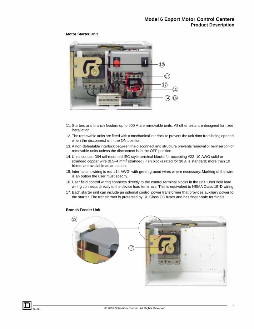
11. Starters and branch feeders up to 600 A are removable units. All other units are designed for fixed installation.
12. The removable units are fitted with a mechanical interlock to prevent the unit door from being opened when the disconnect is in the ON position.
13. A non-defeatable interlock between the disconnect and structure prevents removal or re-insertion of removable units unless the disconnect is in the OFF position.
14. Units contain DIN rail-mounted IEC style terminal blocks for accepting #22–10 AWG solid or stranded copper wire (0.5–4 mm2 stranded). Ten blocks rated for 30 A is standard; more than 10 blocks are available as an option.
15. Internal unit wiring is red #14 AWG, with green ground wires where necessary. Marking of the wire is an option the user must specify.
16. User field control wiring connects directly to the control terminal blocks in the unit. User field load wiring connects directly to the device load terminals. This is equivalent to NEMA Class 1B-D wiring.
17. Each starter unit can include an optional control power transformer that provides auxiliary power to the starter. The transformer is protected by UL Class CC fuses and has finger-safe terminals.
Branch Feeder Unit
12
14
15
17
16
17
12
13
9© 2001 Schneider Electric All Rights Reserved

Model 6 Export Motor Control CentersProduct Description
10
18. A rotary handle is used for unit disconnects 600 A and below. A toggle handle is used on units above 600 A and on COMPAC™ 6 motor starter units. All handles show a clear indication of “I” (ON), “O” (OFF), and TRIP. All handles can support up to three padlocks in the OFF position.
Rotary Handle on Unit Door
19. Tin-plated copper power stabs are spring reinforced to exert the proper clamping force when they are connected to the vertical bus. The stabs are shrouded to protect them from damage during unit maintenance.
Typical Shrouded Power Stabs
20. A first make/last break stab is used to connect functional units to the Protective Conductor (PE) or ground bus before connecting to the power bus.
21. The control station plate can support up to five 22 mm Telemecanique IEC pilot devices.
Control Station Plate
18
19
21
© 2001 Schneider Electric All Rights Reserved 07/01

Model 6 Export Motor Control CentersProduct Description
07/01
Bus Bar Features
1. The main horizontal bus is located at the top of the structure for easy installation, inspection, and maintenance. Partitions completely separate all bus bars from the rest of the assembly.
2. The main horizontal bus bars are tin-plated to make an excellent electrical connection. Current ratings can be increased from 600–2500 A by increasing the number of bars.
3. Bus bar supports meet 50 kA rms short-time current (ICW) for one second per IEC 60439-1 tests. A 70 kA rating is optional.
4. Captive horizontal splice bars have self-contained nuts and hardware to ease installation and reduce the possibility of splice bar loss.
5. The vertical bus contains distribution bus bars within each section that are rated for 600 A of outgoing unit loads. These vertical bars are made of the same material and plating as the horizontal main bus, and are partitioned from the rest of the assembly by insulating material.
6. Each section with vertical bus contains a vertical ground bus (a protective conductor per IEC 60439-1). This bus mates with ground stabs on the rear of each plug-on unit to create a positive ground connection.
7. Vertical bus barriers and wireway openings are built in 3 in. (76 mm) increments. This allows more flexibility when mounting units and decreases wasted enclosure space. The barriers and openings have removable shutters that must be manually removed and replaced.
1
Horizontal Bus Bar Partitions
4
1
3
Tin-Plated Main Horizontal Bus Bars
6
Insulated Vertical Bus in the MCC
5
7
Manual Bus Shutters
11© 2001 Schneider Electric All Rights Reserved

Model 6 Export Motor Control CentersProduct Description
12
8. Neutral bus is optional. If supplied, the neutral bus is made of the same material as the horizontal main power bus. The current rating of the neutral bus is rated at a minimum of 50% of the current rating of the main power bus.
9. At the customer’s request, the optional neutral conductor is connected to outgoing functional units by fixed cable connections wired to each unit that requires a neutral.
10. Each section includes a horizontal ground bus (as a protective conductor per IEC 60439-1) with a captive splice bar. This creates a continuous earthing point for the entire MCC assembly. All conductive structural parts, internal barriers, and units are electrically connected throughout the ground bus system. The horizontal ground bus consists of two 0.25 in. x 2 in. (6 mm x 51 mm) tin-plated copper bars. Each section’s horizontal ground bus has provisions for up to 6 copper or aluminum conductors with cross section dimensions of 10 mm2.
11. Bussing meets the temperature rise requirements of type tests per IEC 60439-1.
Neutral Bus
Horizontal Ground Bus
8
9
11
10
© 2001 Schneider Electric All Rights Reserved 07/01

Model 6 Export Motor Control CentersProduct Description
07/01
2
Main Lugs
Incoming Device Features
1. The Model 6 Export MCC contains separate partitioned compartments for incoming main power cables. All compartments have front access; rear access is not available. The incoming device compartments can be on the left or right end of the MCC line-up.
2. Circuit breakers are available for applications up to 2000 A. Main lugs with mechanical compression (cage) terminals are available for applications up to 2500 A.
3. Incoming devices can enter through the top or bottom of the structure. The compartment is located at the top of the structure in top entry, and at the bottom of the structure in bottom entry.
4. All circuit breaker disconnects 600 A and below, or 1200–2000 A, use a rotary handle. Units from 800–1000 A use a toggle handle. All types of handles clearly indicate the ON (I), OFF (O), and TRIP positions. The unit door cannot be opened while the disconnect is ON. Both rotary and toggle handles can support up to three padlocks in the OFF position.
5. Units have fixed main incoming connections, and cannot be removed or withdrawn from the structure.
6. A neutral terminal can accommodate four-wire systems.
7. Circuit breaker type incoming devices up to 600 A are equipped with MERLIN GERIN COMPACT® NS circuit breakers. Circuit breaker type incoming devices over 600 A are equipped with IEC-rated thermal magnetic circuit breakers manufactured by Square D. High interrupting circuit breakers provide circuit protection and isolation per IEC standard 60947-2.
8. Power system monitors—such as circuit monitors or power meters from POWERLOGIC®—are an option with the incoming device.
7
Thermal Magnetic Circuit Breaker
8
POWERLOGIC Circuit Monitor
13© 2001 Schneider Electric All Rights Reserved

Model 6 Export Motor Control CentersProduct Description
14
Internal Separation Features
1. The Model 6 Export MCC is divided into three areas:
— Bus bars
— Functional units
— Wireways
Terminals for external conductors are part of the functional units.
2. Internal barriers separate units, bus bars, and wireways in order to meet Forms of Separation 2b and 4a per IEC 60439-1. All barriers achieve the IP 20 degree of protection between compartments.
3. All partitions consist of either grounded metal or insulating material.
Internal Barriers of the MCC
Bus bars (behind partition)
Vertical wireway
Functional units
Top horizontal wireway
Functional unit partition
Outgoing terminals
© 2001 Schneider Electric All Rights Reserved 07/01

Model 6 Export Motor Control CentersProduct Description
07/01
Options
The following options are available with Model 6 Export MCCs.
• CE marking
• 70,000 A short-time current (ICW) rating for one second (50,000 A is standard)
• A neutral terminal in an incoming device or four-pole circuit breaker for incoming power
• A neutral conductor wired to each functional unit
• IEC symbols on electrical wiring diagrams
• LT6 solid state overloads on starter units, in place of bimetallic overloads
• Electronic trip circuit breakers with increased trip functions and alarms
• Additional IEC-style relays and timers for starter units
• Up to four auxiliary interlocks wired for remote use in starters
• Wire marking at the ends of wire, based on customer designations
• Factory interwiring and testing between units, complete with drawings
• COMPAC™ 6 starter units through 22 kW
• Automation devices—such as Programmable Logic Controllers (PLCs), remote I/O, and network compatible devices—from MODICON® brand components. These components can accommodate multiple communication protocols, such as MODBUS® PLUS, PROFIBUS®, and DeviceNet®.
COMPAC™ 6 Six-Inch (152 mm) Unit
QUANTUM™ Unit-Mounted PackagePLC Family
15© 2001 Schneider Electric All Rights Reserved

Model 6 Export Motor Control CentersProduct Description
16
© 2001 Schneider Electric All Rights Reserved 07/01
Model 6 Export Motor Control CentersTechnical Overview
07/01
SECTION CONTENTS
SECTION 2—TECHNICAL OVERVIEW . . . . . . . . . . . . . . . . . . . . . . . . . . . . . . . . . . . . . . . . . . . . . . . 18Standards . . . . . . . . . . . . . . . . . . . . . . . . . . . . . . . . . . . . . . . . . . . . . . . . . . . . . . . . . . . . . . . . . . 18
Certifications . . . . . . . . . . . . . . . . . . . . . . . . . . . . . . . . . . . . . . . . . . . . . . . . . . . . . . . . . . . . . . . . 18Rated Voltages . . . . . . . . . . . . . . . . . . . . . . . . . . . . . . . . . . . . . . . . . . . . . . . . . . . . . . . . . . . . . . 18Rated Currents . . . . . . . . . . . . . . . . . . . . . . . . . . . . . . . . . . . . . . . . . . . . . . . . . . . . . . . . . . . . . . 18
Mechanical Data . . . . . . . . . . . . . . . . . . . . . . . . . . . . . . . . . . . . . . . . . . . . . . . . . . . . . . . . . . . . . 18Service Conditions . . . . . . . . . . . . . . . . . . . . . . . . . . . . . . . . . . . . . . . . . . . . . . . . . . . . . . . . . . . . 18
17© 2001 Schneider Electric All Rights Reserved

Model 6 Export Motor Control CentersTechnical Overview
18
SECTION 2—TECHNICAL OVERVIEW
Standards
• IEC 60439-1 Type Tested Assemblies (TTA)
• EN 60439-1 Type Tested Assemblies (TTA)
• IEC 60947-1, 60947-2, 60947-3, 60947-4 (Short Circuit Ratings, Type 2)
• IEC 60529 (Enclosure Degree of Protection)
Certifications
• ASEFA, Low Voltage Agreement Group (LOVAG)
• CE Mark (optional)
Rated Voltages
Rated Currents
Mechanical Data
Service Conditions
Rated insulation voltage 690 Vac
Rated operational voltage up to 690 Vac
Rated impulse withstand voltage 12 kV
Rated frequency up to 60 Hz
Horizontal bus bar (In) 600, 800, 1200, 1600, 2000, 2500 A, ac
Vertical bus bar (In) 600 A, ac
Rated diversity factor 1.0
Rated short-time current (ICW) 50 kA rms for 1 second (70 kA optional)
Rated peak withstand current (IPK) 105 kA rms (154 kA rms optional)
Main circuit breakers 125–2000 A, ac
Main lug compartments 600–2500 A, ac
Branch feeder circuit breakers 16–1200 A, ac
Motor starters up to 500 A, ac max.
Degrees of protection (enclosure type) according to IEC 60529
IP20 (similar to NEMA Type 1)
Option for IP52 (similar to NEMA Type 12)
Option for IP24 for outdoors (similar to NEMA Type 3R)
Forms of separation according to IEC 60439-1
2b, 4a
Electrical connections according to IEC 60439-1
Motor starter units WFF (FFF for RVAT above 225 A)
Circuit breaker units WFF (up to 600 A)/FFF (800-2000 A)
Operating temperature 0 to 40° C
Storage temperature 0 to 40° C
Humidity 0–95% non-condensing
Pollution degree 3 per IEC 60947-1
Altitude 1000 m
© 2001 Schneider Electric All Rights Reserved 07/01

Model 6 Export Motor Control CentersApplication and General Information
07/01
SECTION CONTENTS
SECTION 3—APPLICATION AND GENERAL INFORMATION . . . . . . . . . . . . . . . . . . . . . . . . . . . . . 21Enclosure Types . . . . . . . . . . . . . . . . . . . . . . . . . . . . . . . . . . . . . . . . . . . . . . . . . . . . . . . . . . . . . 21
NEMA Enclosure Types . . . . . . . . . . . . . . . . . . . . . . . . . . . . . . . . . . . . . . . . . . . . . . . . . . . . 21IEC Degrees of Protection . . . . . . . . . . . . . . . . . . . . . . . . . . . . . . . . . . . . . . . . . . . . . . . . . . . . . . 22Surface Appearance and Color . . . . . . . . . . . . . . . . . . . . . . . . . . . . . . . . . . . . . . . . . . . . . . . . . . 24
Main Bus Amps and Material . . . . . . . . . . . . . . . . . . . . . . . . . . . . . . . . . . . . . . . . . . . . . . . . . . . . 25Incoming Devices . . . . . . . . . . . . . . . . . . . . . . . . . . . . . . . . . . . . . . . . . . . . . . . . . . . . . . . . . . . . 26
General Information . . . . . . . . . . . . . . . . . . . . . . . . . . . . . . . . . . . . . . . . . . . . . . . . . . . . . . . 26
Main Lug Compartments . . . . . . . . . . . . . . . . . . . . . . . . . . . . . . . . . . . . . . . . . . . . . . . . . . . 26Main Circuit Breakers . . . . . . . . . . . . . . . . . . . . . . . . . . . . . . . . . . . . . . . . . . . . . . . . . . . . . . 28Wire Size Range for Standard Mechanical Lugs . . . . . . . . . . . . . . . . . . . . . . . . . . . . . . . . . 30
Three-Phase, Four-Wire Systems . . . . . . . . . . . . . . . . . . . . . . . . . . . . . . . . . . . . . . . . . . . . . . . . 31POWERLOGIC® Monitoring . . . . . . . . . . . . . . . . . . . . . . . . . . . . . . . . . . . . . . . . . . . . . . . . . . . . 32POWERLOGIC® Power Meter . . . . . . . . . . . . . . . . . . . . . . . . . . . . . . . . . . . . . . . . . . . . . . . . . . 33
Branch Feeder Units . . . . . . . . . . . . . . . . . . . . . . . . . . . . . . . . . . . . . . . . . . . . . . . . . . . . . . . . . . 35Motor Starter Units . . . . . . . . . . . . . . . . . . . . . . . . . . . . . . . . . . . . . . . . . . . . . . . . . . . . . . . . . . . . 38
Circuit Breaker/Contactor Coordination . . . . . . . . . . . . . . . . . . . . . . . . . . . . . . . . . . . . . . . . 38
Contactor Utilization . . . . . . . . . . . . . . . . . . . . . . . . . . . . . . . . . . . . . . . . . . . . . . . . . . . . . . . . . . . 48IEC Certification . . . . . . . . . . . . . . . . . . . . . . . . . . . . . . . . . . . . . . . . . . . . . . . . . . . . . . . . . . . . . . 49ASEFA/LOVAG Certifications . . . . . . . . . . . . . . . . . . . . . . . . . . . . . . . . . . . . . . . . . . . . . . . . . . . 49
CE Marking . . . . . . . . . . . . . . . . . . . . . . . . . . . . . . . . . . . . . . . . . . . . . . . . . . . . . . . . . . . . . . . . . 50
TABLESModel 6 Export Enclosure Selections . . . . . . . . . . . . . . . . . . . . . . . . . . . . . . . . . . . . . . . . . . . . . 21IEC 60529 Enclosure Classification Designations—First Characteristic Numeral . . . . . . . . . . . 22
IEC 60529 Enclosure Classification Designations—Second Characteristic Numeral . . . . . . . . 23Structural Steel Gauge . . . . . . . . . . . . . . . . . . . . . . . . . . . . . . . . . . . . . . . . . . . . . . . . . . . . . . . . . 24Structure Options and Modifications . . . . . . . . . . . . . . . . . . . . . . . . . . . . . . . . . . . . . . . . . . . . . . 24
Bussing Options and Modifications. . . . . . . . . . . . . . . . . . . . . . . . . . . . . . . . . . . . . . . . . . . . . . . 25Top-Located Main Lug Compartments . . . . . . . . . . . . . . . . . . . . . . . . . . . . . . . . . . . . . . . . . . . . 27Bottom-Located Main Lug Compartments . . . . . . . . . . . . . . . . . . . . . . . . . . . . . . . . . . . . . . . . . . 27
Main Circuit Breaker Unit Interrupting Ratings per IEC 439 . . . . . . . . . . . . . . . . . . . . . . . . . . . . 29Top-Located Main Circuit Breakers . . . . . . . . . . . . . . . . . . . . . . . . . . . . . . . . . . . . . . . . . . . . . . . 29Bottom-Located Main Circuit Breakers . . . . . . . . . . . . . . . . . . . . . . . . . . . . . . . . . . . . . . . . . . . . 29
Main Lug Compartments . . . . . . . . . . . . . . . . . . . . . . . . . . . . . . . . . . . . . . . . . . . . . . . . . . . . . . 30Main and Branch Circuit Breaker Compartments . . . . . . . . . . . . . . . . . . . . . . . . . . . . . . . . . . . . 30Neutral Lug Terminations . . . . . . . . . . . . . . . . . . . . . . . . . . . . . . . . . . . . . . . . . . . . . . . . . . . . . . 30
Four-Wire Options . . . . . . . . . . . . . . . . . . . . . . . . . . . . . . . . . . . . . . . . . . . . . . . . . . . . . . . . . . . 31POWERLOGIC Circuit Monitor Space Requirements . . . . . . . . . . . . . . . . . . . . . . . . . . . . . . . . . 32POWERLOGIC Power Meter Space Requirements . . . . . . . . . . . . . . . . . . . . . . . . . . . . . . . . . . 34
Branch Circuit Breaker Unit Interrupting Ratings per IEC 439 . . . . . . . . . . . . . . . . . . . . . . . . . . . 36Space Requirements for Circuit Breaker Branch Feeder Units . . . . . . . . . . . . . . . . . . . . . . . . . . 37
Motor Starter Unit Interrupting Ratings per IEC 60947-4-1 . . . . . . . . . . . . . . . . . . . . . . . . . . . . . 39Control Voltage Selections . . . . . . . . . . . . . . . . . . . . . . . . . . . . . . . . . . . . . . . . . . . . . . . . . . . . . 40Full Voltage Non-Reversing (FVNR) Starters with Circuit Breaker Disconnects (kW Rated) . . . 41
19© 2001 Schneider Electric All Rights Reserved
Model 6 Export Motor Control CentersApplication and General Information
20
Full Voltage Non-Reversing (FVNR) Starters with Circuit Breaker Disconnects (HP Rated) . . . 43
Full Voltage Reversing (FVR) Starters with Circuit Breaker Disconnects (kW Rated) . . . . . . . . .44Full Voltage Reversing (FVR) Starters with Circuit Breaker Disconnects (HP Rated) . . . . . . . . .46Reduced Voltage Autotransformer (RVAT) Starters with Circuit Breaker Disconnects (kW Rated) . . . . . . . . . . . . . . . . . . . . . . . . . . . . . . . . . . . . . . . . . . . . . . . . . . . . . . . . . . . . . . . . . .47Reduced Voltage Autotransformer (RVAT) Starters with Circuit Breaker Disconnects (HP Rated) . . . . . . . . . . . . . . . . . . . . . . . . . . . . . . . . . . . . . . . . . . . . . . . . . . . . . . . . . . . . . . . . . .47Utilization Categories for Contactors Conforming to IEC 60947-4 . . . . . . . . . . . . . . . . . . . . . . . .48
© 2001 Schneider Electric All Rights Reserved 07/01

Model 6 Export Motor Control CentersApplication and General Information
07/01
SECTION 3—APPLICATION AND GENERAL INFORMATION
Enclosure Types
The Model 6 Export MCC is available in three enclosure classifications per IEC 60529: IP 20, IP 24, and IP 52. The customer should choose the enclosure classification that meets the installation requirements, considering environment and use. In addition to meeting the IEC Degrees of Protection of IP 20, IP 24, and IP 52, the Model 6 Export can meet the NEMA Enclosure Type numbers as shown in the following table.
The NEMA types meet or exceed the test requirement for the associated IEC classifications. NEMA Standards Publication 250 and the UL 50 Standard test for environmental conditions such as corrosion and rust. For this reason, and because tests and evaluations for other characteristics are not identical, the IEC enclosure classifications in the table above cannot be used to convert IEC classification designations to NEMA types.
NEMA Enclosure Types
• Type 1: Intended for indoor use only. Type 1 enclosures are primarily designed to provide protection against contact with an energized interior. Type 1 enclosures are designed for use in locations where normal service conditions exist.
• Type 3R: Intended for outdoor use only. Type 3R enclosures are primarily designed to provide protection against falling rain and sleet, and to remain undamaged by ice formation on the enclosure. They are not intended to provide protection against conditions such as dust, internal condensation, or internal icing. They are not intended for extreme weather conditions.
• Type 12: Intended for indoor use only. Type 12 enclosures are primarily designed to provide some protection against dust, falling dirt, and dripping water. They are not intended to provide protection against conditions such as internal condensation.
Model 6 Export Enclosure Selections
Meets IEC Enclosure Classification
Similar to NEMA Enclosure Type Number
Protection Characteristics
IP 20 1
Protected against the penetration of solid objects that have a diameter greater than or equal to 12.5 mm (0.5 in.) per IEC 60529 test.
Protected against direct finger contact per IEC 60529 test.
Not protected against penetration of water per IEC 60529 test.
Protected against falling dirt per UL 50 test.
Rust resistant per UL 50 test.
IP 24 3R
Protected against the penetration of solid objects that have a diameter greater than or equal to 12.5 mm (0.5 in.) per IEC 60529 test.
Protected against direct finger contact per IEC 60529 test.
Protected against splashing water per IEC 60529 test.
Rainproof per UL 50 test.
External icing per UL 50 test.
Rust resistant per UL 50 test.
IP 52 12
Dust protected per IEC 60529 test.
Protected against direct contact with a 1 mm (0.04 in.) diameter wire per IEC 60529 test.
Protected against splashing water per IEC 60529 test.
Dust tight per UL 50 test.
Drip tight per UL 50 tests.
Rust resistant per UL 50 test.
21© 2001 Schneider Electric All Rights Reserved

Model 6 Export Motor Control CentersApplication and General Information
22
IEC Degrees of Protection
IEC publication 60529, Classification of Degrees of Protection Provided by Enclosures, provides a system for specifying the enclosures of electrical equipment based on the degree of protection they provide.
The IEC designation consists of the letters “IP,” which are usually followed by two numerals (for example, “IP 55”). The first characteristic numeral indicates the degree of protection provided by the enclosure with respect to persons and solid foreign objects entering the enclosure. The second characteristic numeral indicates the degree of protection provided by the enclosure with respect to the harmful ingress of water. The following tables explain the meaning of the two classification numbers.
IEC 60529 Enclosure Classification Designations—First Characteristic Numeral
First Characteristic Numeral
Corresponds to protection of the equipment against penetration of solid objects and protection of personnel against direct contact with live parts.
Protection of the Equipment Protection of Personnel
0 Not protected Not protected
1Protected against the penetration of solid objects having a diameter greater than or equal to 50 mm (2 in.).
Protected against direct contact with the back of the hand (accidental contacts).
2Protected against the penetration of solid objects having a diameter greater than or equal to 12.5 mm (0.5 in.).
Protected against direct finger contact.
3Protected against the penetration of solid objects having a diameter greater than or equal to 2.5 mm (0.1 in.).
Protected against direct contact with a 2.5 mm (0.1 in.) diameter tool.
4Protected against the penetration of solid objects having a diameter greater than 1 mm (0.04 in.).
Protected against direct contact with a 1 mm (0.04 in.) diameter wire.
5
Dust-protected (no harmful deposits).Protected against direct contact with a 1 mm (0.04 in.) diameter wire.
6
Dust-tight.Protected against direct contact with a 1 mm (0.04 in.) diameter wire.
Ø 50 mm
Ø 12. 5 mm
Ø 2,5 mm
Ø 1 mm
© 2001 Schneider Electric All Rights Reserved 07/01

Model 6 Export Motor Control CentersApplication and General Information
07/01
IEC 60529 Enclosure Classification Designations—Second Characteristic Numeral
Second Characteristic Numeral
Corresponds to protection of equipment against penetration of water with harmful effects.
0 Not protected
1
Protected against vertical dripping water (condensation).
2 Protected against dripping water at an angle of up to 15°.
3
Protected against rain at an angle of up to 60°.
4
Protected against splashing water in all directions.
5
Protected against water jets in all directions.
6 Protected against powerful jets of water and waves.
7
Protected against the effects of temporary immersion.
8
Protected against the effects of prolonged immersion under specified conditions.
15
60°
991
mm
(39
in.)
152 mm(6 in.)min
991
mm
(39
in.)
23© 2001 Schneider Electric All Rights Reserved

Model 6 Export Motor Control CentersApplication and General Information
24
Surface Appearance and Color
All metal structural and unit parts are completely painted using an Electro-deposition process, so that interior and exterior surfaces have a complete finish coat both on and between them. The basic process consists of using an iron phosphate pretreatment to improve paint adhesion and a non-chrome sealer rinse to enhance corrosion resistance. The paint process consists of cleaning, rinses, phosphating, non-chrome sealer rinses, prepaint rinses, painting, post-paint rinse, a bake cure, and a cool down.
• Paint is UL-recognized acrylic Electro-deposition baked enamel American National Standards Institute (ANSI) 49 medium light gray.
• All painted parts are able to pass at least 300 hours of salt spray per the American Society for Testing and Materials (ASTM) b117 with less than 1/8 in. (3 mm) loss of paint from a scribed line.
Structural Steel Gauge
Part Description Thickness (Gauge) Thickness (Millimeters)
Corner channels 12 2.6
Back plates: 20–30 in. wide 16 1.4
35 in. wide 14 1.9
End closing plates 16 (Outdoor IP 24: 12 gauge) 1.4
Unit doors14 and 16 (Outdoor IP 24: 12
gauge on outer door)1.9 and 1.4
Side channels 11 2.9
Top and bottom frame 12 2.6
Top and bottom plates 14 1.9
Base channels 10 3.4
Lifting angle 7 4.6
Structure Options and Modifications
Description Standard or Optional
12-in. (305 mm) high pull box Optional
18-in. (457 mm) high pull box Optional
Bottom plate for MCC section Standard
9-in. (229 mm) wide vertical wireway(This option applies only to 25-in./ 635 mm wide sections with plug-in units.)
Optional
Wire tie retainers in vertical wireway Optional
Vertical bus barrier closing shutters Standard
Non-standard exterior color(includes one coat of paint selected by Square D)Consult the factory for specifications that detail primers, paint, thickness, and the application process.
Optional
Fishtape barrier(Prevents fishtapes that enter through the bottom of the structure from rising into the wireway.)
Standard
Rodent barriers Standard
CE Marking(Provides documentation and CE label on the MCC. The customer must choose either a Certificate for Declaration of Incorporation or a Certificate for Declaration of Conformity.)
Optional
© 2001 Schneider Electric All Rights Reserved 07/01

Model 6 Export Motor Control CentersApplication and General Information
07/01
Main Bus Amps and Material
• 600 A tin-plated copper
• 800 A tin-plated copper
• 1200 A tin-plated copper
• 1600 A tin-plated copper—20-in. (508 mm) deep structures only
• 2000 A tin-plated copper—20-in. (508 mm) deep structures only
• 2500 A tin-plated copper—20-in. (508 mm) deep and IP 20 structures only
Bussing Options and Modifications
Description Standard or Optional
600 A vertical bus — tin-plated copper Standard
Bus withstand rating (ICW)(Modifications to increase the bus system withstand to meet available fault current requirements)
50,000 A rms Standard
70,000 A rms Optional
Tin-plated copper vertical ground bus Standard
Copper horizontal ground bus — 1/4 in. x 2 in. (6 mm x 51 mm) — 2 bars Standard
2-in. (51 mm) main/horizontal bus — tin-plated copper Standard
25© 2001 Schneider Electric All Rights Reserved

Model 6 Export Motor Control CentersApplication and General Information
26
Incoming Devices
General Information
Incoming—or main—devices connect power to the motor control center. In most MCC applications, the power system is configured as 3-phase, 4-wire, and the system neutral is not connected to the MCC. If a neutral wire connection is required, a neutral option can be added at the customer’s request (see “Three-Phase, Four-Wire Systems” on page 31). The main power connection to the MCC bus is located at the top or bottom of the structure, entering from the front. Rear connections are not available.
Typically, a main lug or main circuit breaker is used to connect power to the MCC. One of these devices is connected to the horizontal or main bus with a hard bus. The incoming device must be mounted at the top or bottom of the structure, as determined by the customer and the incoming direction of the power connections. The top or bottom location orients incoming device terminals toward the incoming connection for ease of installation.
Main Lug Compartments
• Main lug compartments must be specified in the absence of other incoming line provisions.
• Three-phase, 4-wire main lugs include a neutral assembly for cable connection to other units with solid neutrals.
• Main lug unit short circuit ratings up to 70,000 (ICW) are optional, and can be included at the customer’s request.
Main Circuit Breaker Main Lugs
© 2001 Schneider Electric All Rights Reserved 07/01

Model 6 Export Motor Control CentersApplication and General Information
07/01
Top-Located Main Lug Compartments
System Amps Space (Inches) Space (Millimeters)
3-phase3-wire
6006 152
800
1200 12 305
1600 �
72 18292000 �
2500 �
3-phase4-wire
6009 229
800
1200 � 12 305
1600 �
72 18292000 �
2500 �
� 30 in. (762 mm) wide by 20 in.(508 mm) deep section
� 25 in. (635 mm) wide section with a 9 in. (229 mm) wireway
Bottom-Located Main Lug Compartments
System Amps Space (Inches) Space (Millimeters)
3-phase3-wire
600 18 457
1200 � 36 914
1600 �
72 18292000 �
2500 �
3-phase4-wire
600 18 457
1200 � 36 914
1600 �
72 18292000 �
2500 �
� 25 in. (635 mm) wide section with a 9 in. (229 mm) wireway
� 30 in. (762 mm) wide by 20 in.(508 mm) deep section
27© 2001 Schneider Electric All Rights Reserved

Model 6 Export Motor Control CentersApplication and General Information
28
MERLIN GERIN® COMPACT® NSJ400 Circuit Breaker
Main Circuit Breakers
• Main circuit breaker units are provided with MERLIN GERIN® COMPACT® NS circuit breakers up to 600 A. For circuit breakers above 600 A, Square D IEC-rated thermal magnetic circuit breakers are provided.
• Units are of fixed or removable construction as indicated in the tables on page 29.
NOTE: Removable units have line connections that are withdrawable and fixed load connections (IEC 60439-1 type WFF).
• Circuit breakers provide circuit protection and isolation per IEC standard 947-2.
• MERLIN GERIN disconnect handles are rotary. Square D circuit breaker handles are toggle (M-frame) or rotary (P-frame).
• Disconnect handles are interlocked with the door to prevent the door from opening while the circuit breaker is closed. ON (I), OFF (O), and TRIP positions are clearly indicated on the handle.
• MERLIN GERIN COMPACT NS100, NS160, NS250, and M-frame or P-frame circuit breakers include thermal magnetic trip units as standard. STR22SE electronic trip units are optional (at the customer’s request) on NS100, NS160, and NS250 circuit breakers.
• MERLIN GERIN COMPACT NS400 and NS630 circuit breakers include STR23SE electronic trip units as standard. STR53UE full function electronic trip units are optional at the customer’s request.
• MICROLOGIC® trip systems are available as an option (at the customer’s request) on Square D thermal magnetic circuit breakers.
• Interrupting ratings (ICU) for all circuit breaker units are shown in "Main Circuit Breaker Unit Interrupting Ratings per IEC 439," on page 29.
• All main circuit breakers are high interrupting type “H.”
• Main circuit breakers are 3-pole versions only.
© 2001 Schneider Electric All Rights Reserved 07/01

Model 6 Export Motor Control CentersApplication and General Information
07/01
Main Circuit Breaker Unit Interrupting Ratings per IEC 439
Circuit Breaker Type220/240 Vac
50/60 Hz380/400/415 Vac
50/60 Hz440 Vac50/60 Hz
660/690 Vac50/60 Hz
NS160H
70 kA 70 kA 65 kA
10 kANS250H
NS400H20 kA
NS630H
MH
65 kA 65 kA 65 kA �
Not available
ME
MX
PH
70 kA 70 kA 70 kA �PE
PX
� Self-certified
NOTE: All units are for 3-phase, 3-wire systems. For 3-phase, 4-wire applications, see page 31.
Top-Located Main Circuit Breakers
Circuit Breaker Trip Rating (Amps) Circuit Breaker Type Circuit Breaker FrameSpace
(Inches / Millimeters)
125NS160H 160 A 3-pole
15 / 381(removable)
160
200NS250H 250 A 3-pole
250
400 NS400H 400 A 3-pole 24 / 610(removable)600 NS630H 630 A 3-pole
800 MH/ME/MX1000 A 3-pole
72 / 1829(25W x 20D / 635W x 508D)1000 MH
1200
PH/PE/PX 2000 A 3-pole72 / 1829
(30W x 20D / 762W x 508D)1600
2000
Bottom-Located Main Circuit Breakers
CIrcuit Breaker Trip Rating (Amps) Circuit Breaker Type Circuit Breaker FrameSpace
(Inches / Millimeters)
125NS160H 160 A 3-pole
15 / 381(removable)
160
200NS250H 250 A 3-pole
250
400 NS400H 400 A 3-pole 30 / 762(removable)600 NS630H 630A 3-pole
800 MH/ME/MX1000 A 3-pole
72 / 1829(25W x 20D / 635W x 508D)1000 MH
1200
PH/PE/PX 2000 A 3-pole72 / 1829
(30W x 20D / 762W x 508D)1600
2000
29© 2001 Schneider Electric All Rights Reserved

Model 6 Export Motor Control CentersApplication and General Information
30
Wire Size Range for Standard Mechanical Lugs
Main Lug Compartments
Main Lug AmpsLug Wire Range
(mm2
AWG)Lugs Per Phase/Neutral
60085–240
3/0 AWG–500 kcmil2
80085–240
3/0 AWG–500 kcmil3
120085–240
3/0 AWG–500 kcmil4
160095–400
3/0 AWG–750 kcmil6
200095–400
3/0 AWG–750 kcmil6
250095–400
3/0 AWG–750 kcmil6
Main and Branch Circuit Breaker Compartments
Circuit Breaker Frame AmpsLug Wire Range
(mm2
AWG)
Lugs Per Phase
NS100 1001.5–9.5#16-3/0
1
NS125 125
NS160 160
NS200 200 1.5–185#16 AWG-350 kcmilNS250 250
NS400 40035–300
#2 AWG-600 kcmil
NS630 60085–240
3/0 AWG-500 kcmil2
MA/MH
80095–240
3/0 AWG-500 kcmil3
100095–400
3/0 AWG-750 kcmil
PA/PH 1200–200095–400
3/0 AWG-750 kcmil6
Neutral Lug Terminations
ApplicationLug Wire Range
(mm2
AWG)
100 A main or branch(1) 4–50
(1) #12–1/0
200/225 A main or branch(1) 25–150
(1) #4–300 kcmil
400 A main or branch(1) 50–300/(2) 50–120
(1) #1–600 kcmil/(2) #1–250 kcmil
600 A top-located main circuit breaker(3) 95–240
(3) 3/0–500 kcmil600 A branch or bottom main circuit breaker/fusible switch
800–2000 A main or branch(4) 95–300
(4) 3/0–750 kcmil
600–2500 A main lugsSee the table, "Main Lug Compartments"
above
Neutral rating 1200 A max.(4) 95–300/(1) 25–185
(4) 3/0–750 kcmil/(1) #6–300 kcmil
© 2001 Schneider Electric All Rights Reserved 07/01

Model 6 Export Motor Control CentersApplication and General Information
07/01
Three-Phase, Four-Wire Systems
If the motor control center contains only motor loads, and no future four-wire loads are anticipated, it is not necessary to bring the neutral conductor into the MCC. If the customer requests, an optional neutral lug assembly can be provided in the incoming main section in order to terminate a neutral conductor. Additional lugs can be added for connections to the neutral.
When four-wire loads are present in the MCC, solid neutral bussing can be provided in individual sections and connected to provide a continuous neutral bar. To increase accessibility, incoming and outgoing neutral conductors can be terminated at the neutral lug assembly located in each vertical wireway. Lugs are not provided, but holes are pre-drilled to accommodate user-mounted lugs.
Four-Wire Examples
Four-Wire Options
Description Application Space
Neutral lug termination �(Provides termination for the fourth wire on 3-phase/4-wire systems)
100 A branch
0
160/250 A main or branch
400 A main or branch �
600 A top main
600 A bottom main or branch
800 A main or branch
1000 A main or branch
1200 A main or branch
1600–2500 A main or branch
600–2500 A main lugs See the main lug compartment tables on
page 27.
Solid neutral bus�(Price per section—20 in. (508 mm) deep sections required)
600–800 A (1) 1.5 in. x 0.25 in. cu (38 mm x 6 mm)
01200–2500 A (2) 1.5 in. x 0.25 in. cu (38 mm x 6 mm)Max 100% rating is 1200 A
Neutral bus drop�Provides vertical extension of solid neutral bus into the vertical wireway to facilitate neutral connections from units.
� As an option, neutrals in units can factory connected at the customer’s request.
Disconnect
Cable
ABC
Cable
Disconnect
Neutral lugterminationassembly
ANBC
Figure 3
Disconnect
ABC
Figure 1 Figure 2
Neutral lugterminationassembly
Solidneutral bus
Neutral lugterminationassembly
Neutraldistributionunit
31© 2001 Schneider Electric All Rights Reserved

Model 6 Export Motor Control CentersApplication and General Information
32
POWERLOGIC® Monitoring
The POWERLOGIC Circuit Monitor from Schneider Electric is a multifunction instrumentation, data acquisition, and control device that replaces conventional metering, data acquisition, and control equipment. POWERLOGIC monitors replace discrete meters due to their ability to communicate metering information via an RS-485 (RS-422 compatible) communication channel to a personal computer, local display, PLC, or DCS system.
Circuit Monitor Model Application Space
CM-2250(3-phase, 3-wire system)
Instrumentation and waveform capture See "POWERLOGIC Circuit Monitor Space Requirements"belowCM-2350
(3-phase, 3-wire system)Instrumentation, waveform capture, and extended memory
IOM-11 I/O module with 4 status inputs, 1 KYZ pulse output
0IOM-44
I/O module with 4 status inputs, 1 KYZ pulse output, and 3 form-C relay outputs
IOM-4444-20I/O module with 4 status inputs, 1 KYZ pulse output, 3 form-C relay outputs, 4 analog inputs, and 4 analog outputs (4–20 mA dc)
POWERLOGIC Circuit Monitor Space Requirements
Main Device Type Space (Inches / Millimeters)
Main Lugs
Top- or bottom-located, 600–1200 A 15 / 381
Top- or bottom-located, 1600–2500 A 0
Main Breaker
Top- or bottom-located, 250 A 21 / 533
Top- or bottom-located, 400 A15 / 381
Top- or bottom-located, 600 A without Form U231 (neutral lug termination)
Top-located, 600 A with Form U231 (neutral lug termination) 30 / 762
Bottom-located, 600 A with Form U231 (neutral lug termination) 27 / 686
Top- or bottom-located, 800–2000 A 0
© 2001 Schneider Electric All Rights Reserved 07/01

Model 6 Export Motor Control CentersApplication and General Information
07/01
POWERLOGIC® Power Meter
The POWERLOGIC Power Meter is designed for use in basic power metering applications. It can replace conventional metering devices such as ammeters, voltmeters, and watt-hour meters, and provides powerful capabilities not offered by analog metering. The MCC Power Meter option includes the Power Meter module, front mounted display for easy viewing, required current transformers, and control power fusing. The Power Meter is available on incoming main devices or branch feeder devices. This option can offer an economical advantage in MCCs that require multiple analog meters for voltage, current, and watt-hours.
Power Meter Model Application System Space
PM600 and PMD32Power Meter display plus module with instrumentation functions and 0.25% accuracy
3PH3W MCC
See the table, "POWERLOGIC Power Meter Space Requirements," on page 34.
3PH4W MCC
PM620 and PMD32Power Meter display plus module with PM-600 functions, date/time stamp, THD/thd, neutral current, and demand values
3PH3W MCC
3PH4W MCC
PM650 and PMD32Power Meter display plus module with PM-620 functions, min./max. readings, alarm/relay functions, and event and data logging
3PH3W MCC
33© 2001 Schneider Electric All Rights Reserved

Model 6 Export Motor Control CentersApplication and General Information
34
POWERLOGIC Power Meter Space Requirements
Device TypeAdditional Space Requirements
(Inches/Millimeters)
Main Lugs
Top-located, 600–1200 A9 / 229
Bottom-located, 600–1200 A
Top- or bottom-located, 1600–2500 A 0
Main Circuit Breaker
Top-or bottom-located, 125–250 A
9 / 229Top- or bottom-located, 400 A
Top- or bottom-located, 600 A, without Form U231 (neutral lug termination)
Top-located, 600 A, with Form U231 (neutral lug termination) 6 / 152
Bottom-located, 600 A, with Form U231 (neutral lug termination) 9 / 229
Top- or bottom-located, 800–2000 A 0
Branch Circuit Breaker
16–100 A
9 / 229125–250 A
400–600 A
800–1200 A 0
© 2001 Schneider Electric All Rights Reserved 07/01

Model 6 Export Motor Control CentersApplication and General Information
07/01
Branch Feeder Units
Branch feeder units include the following features:
• MERLIN GERIN® COMPACT® NS circuit breakers up to 600 A. For circuit breakers above 600 A, Square D IEC-rated thermal magnetic circuit breakers are provided.
• Units are of fixed or removable construction as indicated in the table, "Space Requirements for Circuit Breaker Branch Feeder Units," on page 37.
NOTE: Removable units have line connections that are withdrawable and fixed load connections (IEC 60439-1 type WFF).
• Circuit breakers provide branch circuit protection and isolation per IEC standard 947-2.
• Standard interrupting ratings are shown in the table, "Branch Circuit Breaker Unit Interrupting Ratings per IEC 439," on page 36. At the customer’s request, optional high interrupting or electronic trip circuit breakers can be supplied.
• MERLIN GERIN disconnect handles are rotary. Square D circuit breaker handles are toggle (M-frame) or rotary (P-frame).
• Disconnect handles are interlocked with the door to prevent the door from opening while the circuit breaker is closed. ON (I), OFF (O), and TRIP positions are clearly indicated on the handle.
• MERLIN GERIN COMPACT NS100, NS160, NS250, and M-frame or P-frame circuit breakers include thermal magnetic trip units as standard. STR22SE electronic trip units are optional (at the customer’s request) on NS100, NS160, and NS250 circuit breakers.
• MERLIN GERIN COMPACT NS400 and NS630 circuit breakers include STR23SE electronic trip units as standard. STR53UE full function electronic trip units are optional at the customer’s request.
• MICROLOGIC® trip systems are available as an option (at the customer’s request) on Square D thermal magnetic circuit breakers.
• Interrupting ratings (ICU) for all breaker units are shown in the table, "Branch Circuit Breaker Unit Interrupting Ratings per IEC 439," on page 36.
Circuit Breaker Branch
35© 2001 Schneider Electric All Rights Reserved

Model 6 Export Motor Control CentersApplication and General Information
36
Branch Circuit Breaker Unit Interrupting Ratings per IEC 439
Circuit Breaker Type220/240 Vac
50/60 Hz380/400/415 Vac
50/60 Hz440 Vac50/60 Hz
660/690 Vac50/60 Hz
Standard Interrupting
NS100N
70 kA
25 kA 25 kA
8 kANS160N36 kA 35 kA
NS250N
NS400N45 kA 42 kA 10 kA
NS630N
MA 30 kA 30 kA 30 kA �Not available
PA 50 kA 50 kA 50 kA �
High Interrupting
NS100H �
70 kA 70 kA 65 kA
10 kANS160H �
NS250H �
NS400H �20 kA
NS630H �
MH � 65 kA 65 kA 65 kA �Not available
PH � 70 kA 70 kA 70 kA �
Standard Electronic Trip
NS100N �
70 kA
25 kA 25 kA
8 kANS160N � 36 kA 35 kA
NS250N � 36 kA 35 kA
NS400N 45 kA 42 kA
10 kA
NS630N 45 kA 42 kA
NS100H �
70 kA 65 kA
NS160H �
NS250H �
NS400H20 kA
NS630H
MX � 65 kA 65 kA 65 kA �Not available
PX � 70 kA 70 kA 70 kA �
Full Function Electronic Trip
NS400N �
70 kA
45 kA 42 kA 10 kANS630N �
NS400H �70 kA 65 kA 20 kA
NS630H �
ME � 65 kA 65 kA 65 kA �Not available
PE � 70 kA 70 kA 70 kA �
� Self-certified
� Optional feature added at the customer’s request
© 2001 Schneider Electric All Rights Reserved 07/01

Model 6 Export Motor Control CentersApplication and General Information
07/01
Space Requirements for Circuit Breaker Branch Feeder Units
Circuit Breaker Trip Rating (Amps)
Circuit Breaker Type Circuit Breaker Frame Space (Inches/Millimeters)
16
NS100N 100 A 3-pole12 / 305
(removable)
25
32
40
50
63
80
100
125NS160N 160 A 3-pole
15 / 381(removable)
160
200NS250N 250 A 3-pole
250
400 NS400N 400 A 3-pole 30 / 762(removable)600 NS630N 630 A 3-pole
800MA 1000 A 3-pole
72 / 1829(25W x 20D / 635W x 508D)1000
1200 PA 2000 A 3-pole72 / 1829
(30W x 20D / 762W x 508D)
37© 2001 Schneider Electric All Rights Reserved
Model 6 Export Motor Control CentersApplication and General Information
38
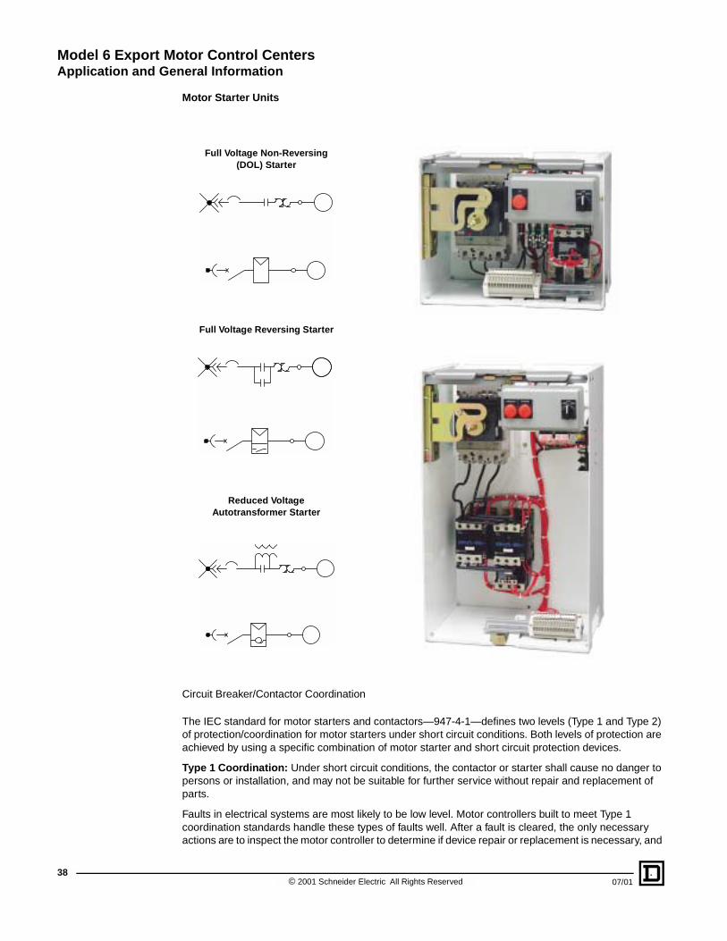
Motor Starter Units
Circuit Breaker/Contactor Coordination
The IEC standard for motor starters and contactors—947-4-1—defines two levels (Type 1 and Type 2) of protection/coordination for motor starters under short circuit conditions. Both levels of protection are achieved by using a specific combination of motor starter and short circuit protection devices.
Type 1 Coordination: Under short circuit conditions, the contactor or starter shall cause no danger to persons or installation, and may not be suitable for further service without repair and replacement of parts.
Faults in electrical systems are most likely to be low level. Motor controllers built to meet Type 1 coordination standards handle these types of faults well. After a fault is cleared, the only necessary actions are to inspect the motor controller to determine if device repair or replacement is necessary, and
Full Voltage Non-Reversing (DOL) Starter
Full Voltage Reversing Starter
Reduced Voltage Autotransformer Starter
© 2001 Schneider Electric All Rights Reserved 07/01

Model 6 Export Motor Control CentersApplication and General Information
07/01
to reset the circuit breaker or replace the fuses. In situations where available fault currents are high and any period of maintenance downtime is crucial, a higher degree of coordinated protection may be desirable.
Many industries depend on continuous operation of a critical manufacturing process. Under these conditions, Type 1 protection may not adequately prevent damage to motor starter components, and Type 2 coordination is needed.
Type 2 Coordination: Under short circuit conditions, the contactor or starter shall cause no danger to persons or installation, and shall be suitable for further use. The risk of contact welding is recognized, in which case the manufacturer shall indicate the measures to take in regards to equipment maintenance.
Type 2 coordination does not permit damage to the starter beyond light contact welding, which is easily separated by a screwdriver or several coil operations. Type 2 coordination does not allow parts replacement (except for fuses), and requires that all parts remain in service. In addition to providing basic electrical and fire protection, it also minimizes lost production and unscheduled disruptions by eliminating the downtime needed to replace or repair a starter.
To achieve Type 2 coordination in a motor starter, the manufacturer must:
• Select the proper circuit breaker, motor contactor, and overload relay according to the motor current rating.
• Select the circuit breaker according to the short circuit current that will be broken.
• Verify that the components perform properly during short circuit current breaking operations. For example, the manufacturer verifies that there is no contactor or overload relay damage in the event of a short circuit.
The Model 6 Export MCC starter units below 660 V are coordinated for Type 2 protection levels per IEC 947-4-1. The combination of starter and circuit breakers below 660 V in this catalog have undergone full scale testing, according to IEC 947-4-1 in European laboratories. The level of coordination of starters and circuit breakers meets Type 2 requirements at the level of short circuit current listed in the selection table below.
The Type 2 coordination tests have been witnessed, and IEC third parties (ASEFA/LOVAG) have certified the results.
Motor Starter Unit Interrupting Ratings per IEC 60947-4-1 �
Circuit Breaker Type220/240 Vac50/60 Hz �
380/400/415 Vac50/60 Hz �
440/480 Vac50/60 Hz �
660/690 Vac50/60 Hz
NS100N
70 kA
25 kA 25 kA
8 kANS160N36 kA 35 kA
NS250N
NS80H
70 kA 70 kA 65 kA
6 kA
NS100H
10 kANS160H
NS250H
NS400H20 kA
NS630H
� ASEFA/LOVAG certificates are available.
Note: Type N (standard interrupting) circuit breakers are supplied as standard, unless the customer’s short circuit current rating exceeds the interrupting rating listed for the Type N circuit breakers. Type H (high interrupting) circuit breakers are supplied for applications that exceed the Type N ratings. Type H circuit breakers can also be supplied as an option at the customer’s request.
39© 2001 Schneider Electric All Rights Reserved

Model 6 Export Motor Control CentersApplication and General Information
40
Starter units in the Model 6 IEC MCC include the following:
• MERLIN GERIN® COMPACT® NS magnetic circuit breakers. Optional: an electrical trip unit can be substituted for a standard magnetic-only trip unit at the customer’s request.
• TELEMECANIQUE® D-line or F-line ac contactors rated for IEC utilization category AC-3 inductive applications.
• TELEMECANIQUE LR2 or LR9 solid state overload relays rated for class 10 trip class motor protection. Optional: Class 20 or LT6 multifunction protection relays can be substituted for the standard class 10 protection at the customer’s request.
• Units below 660 V contain control power transformers for contactor control per the standard control voltage (see the table below, "Control Voltage Selections").
• UL Class CC fuses in the starter unit for primary and secondary protection of the control power transformer.
• Optional control voltages for contactor and remote control are available at the customer’s request (see the table below, "Control Voltage Selections").
• Plug-on construction that meets the definition of a removable part per IEC 60439-1. The power connections on the line side are withdrawable. External connections for the motor and control terminals are fixed connections (IEC 60439-1 Type WFF).
Control Voltage Selections
Main Voltage Standard Control Voltage Optional Control Voltage (customer request)
220/240 Vac, 50 Hz 110 V, 50 Hz220 V, 50 Hz (line to line)
24 V, 50 Hz
380/400/415 Vac, 50 Hz 110 V, 50 Hz
220 V, 50 Hz (transformer secondary)
220 V, 50 Hz (line to neutral)
24 V, 50 Hz
380 V, 50 Hz (line to line)
440 Vac, 50 Hz 110 V, 50 Hz220 V, 50 Hz (transformer secondary)
24 V, 50 Hz
660/690 Vac, 50 Hz � 110 V, 50 Hz
220 V, 50 Hz
24 V, 50 Hz
380 V, 50 Hz
480 Vac, 60 Hz 120 V, 60 Hz24 V, 60 Hz
480 V, 60 Hz (line to line)
� The customer must supply separate control power to these units.
© 2001 Schneider Electric All Rights Reserved 07/01

Model 6 Export Motor Control CentersApplication and General Information
07/01
Full Voltage Non-Reversing (FVNR) Starters with Circuit Breaker Disconnects (kW Rated)
Motor Kilowatt RatingUnit Amp
Rating
AC-3 Duty IEC Contactor
Type
Overload Relay
Circuit Breaker
TypeC/B Amps
Space (In./mm)220/230/
240 V380/400/415 V
440 V 660/690 V �
0.09/0.12 0.18/0.25 0.25 – 0.63–1
LC1D09
LR2D1305
NS080HMA
1.5
6 / 152 �
0.18 0.370.37/0.55
0.75 1–1.6 LR2D1306
2.5– – – 1 1.2–2 LR2D13X6
0.25–0.37 0.55/0.750.75/1.1
1.5 1.6–2.5 LR2D1307
– – – 2.2/32.5–4 LR2D1308
6.30.55/0.75 1.1/1.5 1.5 – LC1D18
– – – 44–6
LC1D09LR2D1310
1.1 2.2 2.2/3 – LC1D25
– – – 5.55.5–8
LC1D09LR2D1312
12.5
1.5 3 4 – LC1D32
– – – 7.57–10
LC1D12LR2D1314
2.2 4 – –LC1D32
3 5.5 5.5 – 9–12LR2D1316
– – – 10 9–13 LC1D18
25– – – 1512–18
LC1D25LR2D1321
4 7.5 7.5 –LC1D32
– – – 18.517–25 LR2D1322
50
5.5/6.3 10/11 10/11 –
LC1D40
25
7.5 15 15 – 23–32 LR2D3353
50
– – – 3030–40 LR2D3355
10 18.5 18.5/22 –
LC1D50– – – 3337–44 LR2D3357
11 22 – –
� The 660/690 V units are self-certified for Type 1 coordination per IEC 947-4-1.
� COMPAC™ 6 units
41© 2001 Schneider Electric All Rights Reserved

Model 6 Export Motor Control CentersApplication and General Information
42
0.18 0.370.37/0.55
0.75 1–1.6
LC1D09
LR2D1306
NS100-MA
2.5
12 / 305
– – – 1 1.2–2 LR2D13X6
0.25/0.37 0.55/0.750.75/1.1
1.5 1.6–2.5 LR2D1307
0.55/0.75 1.1/1.5 1.5 2.2/3 2.5–4
LC1D40
LR2D13086.3
1.1 2.2 2.2/3 4 4–6 LR2D1310
– – – 5.55.5–8 LR2D1312
12.5
1.5 3 4
– – – 7.57–10
LC1D12LR2D1314
2.2 4 –LC1D40
3 5.5 5.5 9–12LR2D1316
– – – 10 9–13 LC1D18
25– – – 1512–18
LC1D25LR2D1321
4 7.5 7.5 – LC1D40
– – – 18.517–25
LC1D32LR2D3322
50
5.5/6.3 10/11 10/11 – LC1D40 25
7.5 15 15 23–32 LC1D80 LR2D3353
50
– – – 30 30–40 LC1D40 LR2D3355
– – – 33 37–50 LC1D50 LR2D3357
10/11 18.5 18.5/22 30–40 LC1D80 LR2D3355
– – – 3737–50
LC1D65LR2D3357
– 22 – 45LC1D80
15 – – 48–50 LR2D3359
– – – 55 60–100 LC1D115 LR9D5367
100
21 / 533
18.5 30 30/37 48–64LC1D80
LR2D3359 12 / 305
22 37 45 63–76 LR2D3363
21 / 53330 45 55 75 60–100
LC1D115LR9D5367
– 55 – 90–115LR9D5369 NS160-MA 150
37/45 75 75/90 90/110 90–150 LC1D150
– – – 132/160 132–220 LC1F265
LR9F5371 NS250-MA 220 42 / 106755 90 110 132–185 LC1F185
– 110 132 132–220 LC1F225
– – – 200/220 200–320 LC1F330
LR9F7375
NS400-MA 320 48 / 121975 132 160 200–265 LC1F265
– – – 250 200–300 LC1F400 NS630-MA 500 72 / 1829
90 160 200 200–320 LC1F330 NS400-MA 320 48 / 1219
– – – 335 300–500 LC1F500
LR9F7379 NS630-MA 500 72 / 1829110 200220/250
300–400 LC1F400
132/150 220/250 300 300–500 LC1F500
Full Voltage Non-Reversing (FVNR) Starters with Circuit Breaker Disconnects (kW Rated) (Continued)
Motor Kilowatt RatingUnit Amp
Rating
AC-3 Duty IEC Contactor
Type
Overload Relay
Circuit Breaker
TypeC/B Amps
Space (In./mm)220/230/
240 V380/400/415 V
440 V 660/690 V �
� The 660/690 V units are self-certified for Type 1 coordination per IEC 947-4-1.
� COMPAC™ 6 units
© 2001 Schneider Electric All Rights Reserved 07/01

Model 6 Export Motor Control CentersApplication and General Information
07/01
NOTE: The component selections below are based on motor full load amps per the National Electrical Code Table 430-150 for 1800 rpm, NEMA Design B motors. For motors with rated speeds of 1200 rpm or lower, or non-NEMA Design B, obtain the actual motor full load amps and consult the factory.
Full Voltage Non-Reversing (FVNR) Starters with Circuit Breaker Disconnects (HP Rated)
Motor Horsepower Rating @ 480 V
Unit Amp RatingAC3 Duty IEC
Contactor TypeOverload Relay
TypeCircuit Breaker
Type �C/B
AmpsSpace
(In./mm)
0.33 0.63–1
LC1D09
LR2D1305
NS080HMA
1.5
6 / 152 �
0.5/0.75 1–1.6 LR2D13062.5
1 1.6–2.5 LR2D1307
1.5/2 2.5–4 LC1D18 LR2D13086.3
3 4–6 LC1D25 LR2D1310
5 5.5–8
LC1D32
LR2D131212.5
7.5 9–12 LR2D1316
10 12–18 LR2D132125
15 17–25LC1D40
LR2D3322
20 23–32 LR2D335350
25/30 30–40 LC1D50 LR2D3355
0.5/0.75 1–1.6LC1D09
LR2D1306
NS100-MA
2.5
12 / 305
1 1.6–2.5 LR2D1307
1.5/2 2.5–4
LC1D40
LR2D13086.3
3 4–6 LR2D1310
5 5.5–8 LR2D131212.5
7.5 9–12 LR2D1316
10 12–18 LR2D132125
15 17–25 LR2D3322
20 23–32
LC1D80
LR2D335350
25 30–40 LR2D3355
30 37–50 LR2D3357
10040 48–63 LR2D3359
50/60 63–80 LR2D3363
75 60–100 LC1D115 LR9D536721 / 533
100 90–150 LC1D150 LR9D5369 NS160-MA 150
125 132–185 LC1F185LR9F5371 NS250-MA 220 42 / 1067
150 132–220 LC1F225
200 200–265 LC1F265LR9F7375 NS400-MA 320 48 / 1219
250 200–330 LC1F330
300/350/400 300–500 LC1F500 LR9F7379 NS630-MA 500 72 / 1829
� The “–” is replaced with an “N” for standard interrupting, or “H” for high interrupting.
� COMPAC™ 6 units
43© 2001 Schneider Electric All Rights Reserved

Model 6 Export Motor Control CentersApplication and General Information
44
Full Voltage Reversing (FVR) Starters with Circuit Breaker Disconnects (kW Rated)
Motor Kilowatt RatingUnit Amp
Rating
AC3 Duty IEC Contactor
Type
Overload Relay
Circuit Breaker Type �
C/B AmpsSpace
(In./mm)220/230/240 V
380/400/415 V
440 V 660/690 V �
0.09/0.12 0.18/0.25 0.25 – 0.63–1
D09
LR2D1305
NS080HMA
1.5
6 / 152 �
0.18 0.370.37/0.55
0.75 1–1.6 LR2D1306
2.5– – – 1 1.2–2 LR2D13X6
0.25/0.37 0.55/0.75 0.75/1.1 1.5 1.6–2.5 LR2D1307
– – – 2.2/32.5–4 LR2D1308
6.30.55/0.75 1.1/1.5 1.5 – D18
– – – 44–6
D09LR2D1310
1.1 2.2 2.2/3 – D25
– – – 5.55.5–8
D09LR2D1312
12.5
1.5 3 4 – D32
– – – 7.57–10
D12LR2D1314
2.2 4 – –D32
3 5.5 5.5 – 9–12LR2D1316
– – – 10 9–13 D18
25– – – 1512–18
D25LR2D1321
4 7.5 7.5 –D32
– – – 18.5 17–25 LR2D1322 50
0.18 0.370.37/0.55
0.75 1–1.6
D09
LR2D1306
NS100–MA
2.5 12 / 305– – – 1 1.2–2 LR2D13X6
0.25/0.37 0.55/0.75 0.75/1.1 1.5 1.6–2.5 LR2D1307
0.55/0.75 1.1/1.5 1.52.5–4
D40LR2D1308
6.3
24 / 610
– – – 2.2/3 D09 12 / 305
1.1 2.2 2.2/34–6
D40LR2D1310
24 / 610
– – – 4D09 12 / 305
– – – 5.55.5–8 LR2D1312
12.5
1.5 3 4 D40 24 / 610
– – – 7.57–10
D12LR2D1314
12 / 305
2.2 4 –D40 24 / 610
3 5.5 5.5 9–12LR2D1316
– – – 10 9–13 D18
2512 / 305
– – – 1512–18
D25LR2D1321
4 7.5 7.5 – D40 24 / 610
� The 660/690 V units are self-certified for Type 1 coordination per IEC 947-4-1.
� The “–” is replaced with an “N” for standard interrupting, or “H” for high interrupting.
� COMPAC™ 6 units
© 2001 Schneider Electric All Rights Reserved 07/01

Model 6 Export Motor Control CentersApplication and General Information
07/01
– – – 18.517–25
D32 LR2D1322
NS100–MA
50 12 / 305
5.5/6.3 10/11 10/11 – D40 LR2D332225
24 / 610
7.5 15 15 23–32 D80 LR2D3353
– – – 30 30–40 D40 LR2D3355
50
– – – 33 37–50 D50 LR2D3357
10/11 18.5 18.5/22 30–40 D80 LR2D3355
– – – 3737–50
D65LR2D3357
– 22 –
D8015 – – 48–50 LR2D3359
– – – 45 37–50 LR2D3357
100– – – 55 60–100 D115 LR9D5367 30 / 762
18.5 30 30/37 48–63D80
LR2D335924 / 610
22 37 45 63–80 LR2D3363
30 45 55 75 60–100D115
LR9D5367 100
30 / 762– 55 – 90–115LR9D5369 NS160–MA 150
37/45 75 75/90 90/110 90–150 D150
– – – 132/160 132–220 F265
LR9F5371 NS250–MA 220 54 / 137255 90 110 132–185 F185
– 110 132 132–220 F225
– – – 200/220 200–320 F330
LR9F7375
NS400–MA 320
72 / 182975 132 160 200–265 F265
– – – 250 200–300 F400 NS630–MA 500
90 160 200 200–320 F330 NS400–MA 320
Full Voltage Reversing (FVR) Starters with Circuit Breaker Disconnects (kW Rated) (Continued)
Motor Kilowatt RatingUnit Amp
Rating
AC3 Duty IEC Contactor
Type
Overload Relay
Circuit Breaker Type �
C/B AmpsSpace
(In./mm)220/230/240 V
380/400/415 V
440 V 660/690 V �
� The 660/690 V units are self-certified for Type 1 coordination per IEC 947-4-1.
� The “–” is replaced with an “N” for standard interrupting, or “H” for high interrupting.
� COMPAC™ 6 units
45© 2001 Schneider Electric All Rights Reserved

Model 6 Export Motor Control CentersApplication and General Information
46
NOTE: The component selections below are based on motor full load amps per National Electrical Code Table 430-150 for 1800 rpm, NEMA Design B motors. For motors with rated speeds of 1200 rpm or lower, or non-NEMA Design B, obtain the actual full motor load amps and consult the factory.
Full Voltage Reversing (FVR) Starters with Circuit Breaker Disconnects (HP Rated)
Motor Horsepower Rating @ 480 V
Unit Amp RatingAC3 Duty IEC
Contactor TypeOverload Relay
TypeCircuit Breaker
Type �C/B Amps
Space (Inches/Millimeters)
0.33 0.63–1
D09
LR2D1305
NS080HMA
1.5
6 / 152 �
0.5/0.75 1–1.6 LR2D13062.5
1 1.6–2.5 LR2D1307
1.5/2 2.5–4 D18 LR2D13086.3
3 4–6 D25 LR2D1310
5 5.5–8
D32
LR2D131212.5
7.5 9–12 LR2D1316
10 12–18 LR2D1321 25
0.5/0.75 1–1.6D09
LR2D1306
NS100–MA
2.5 12 / 3051 1.6–2.5 LR2D1307
1.5/2 2.5–4
D40
LR2D13086.3
24 / 610
3 4–6 LR2D1310
5 5.5–8 LR2D131212.5
7.5 9–12 LR2D1316
10 12–18 LR2D132125
15 17–25 LR2D3322
20 23–32
D80
LR2D335350
25 30–40 LR2D3355
30 37–50 LR2D3357
10040 48–63 LR2D3359
50/60 63–80 LR2D3363
75 60–100 D115 LR9D536730 / 762
100 90–150 D150 LR9D5369 NS160–MA 150
125 132–185 F185 LR9F5371NS250–MA 220 54 / 1372
150 132–220 F225 LR9F7371
200 200–265 F265 LR9F7375 NS400–MA 320 72 / 1829
� The “–” is replaced with an “N” for standard interrupting, or “H” for high interrupting.
� COMPAC™ 6 units
© 2001 Schneider Electric All Rights Reserved 07/01

Model 6 Export Motor Control CentersApplication and General Information
07/01
NOTE: The component selections below are based on motor full load amps per the National Electrical Code Table 430-150 for 1800 rpm, NEMA Design B motors. For motors with rated speeds of 1200 rpm or lower, or non-NEMA Design B, obtain the actual motor full load amps and consult the factory.
Reduced Voltage Autotransformer (RVAT) Starters with Circuit Breaker Disconnects (kW Rated)
Motor Kilowatt RatingUnit Amp
RatingAC3 Duty IEC
Contactor TypeOverload
Relay Type
Circuit Breaker Type �
C/B Amps
Space (In./mm)220/230/240 V 380/400/415 V 440 V
10/11 18.5 18.5/22 30–40 LC1D80 LR2D3355
NS100-MA
50
60 / 1524(20D / 508 D)
– – –37–50
LC1D65LR2D3357
– 22 –LC1D80
15 – – 48–50 LR2D3359
– – – 60–100 LC1D115 LR9D5367
10018.5 30 30/37 48–63
LC1D80LR2D3359
22 37 45 63–80 LR2D3363
30 45 55 60–100LC1D115
LR9D5367
– 55 – 90–115LR9D5369 NS160-MA 150
37/45 75 75/90 90–150 LC1D150
– – – 132–220 LC1F265
LR9F5371 NS250-MA 22055 90 110 132–185 LC1F185 72 / 1829(20D / 508 D)– 110 – 132–220 LC1F225
75 132 132/160 200–265 LC1F265
LR9F7375
NS400–MA 320
72 / 1829(30W x 20D /
762W x 508D)
– – – 200–300 LC1F400 NS630-MA 500
90 160 200 200–320 LC1F330 NS400-MA 320
– – – 300–500 LC1F500
LR9F7379 NS630-MA 500110 200 220/250 300–400 LC1F400
132/150 220/250 300 300–500 LC1F500
� The “–” is replaced with an “N” for standard interrupting, or an “H” for high interrupting.
NOTE: Sections with RVAT starters require single shipping splits.
Reduced Voltage Autotransformer (RVAT) Starters with Circuit Breaker Disconnects (HP Rated)
Motor Horsepower Rating @ 480 V
Unit Amp RatingAC3 Duty IEC
Contactor TypeOverload Relay
TypeCircuit Breaker
Type �C/B Amps
Space (In./mm)
25 30–40
LC1D80
LR2D3355
NS100–MA
50
60 / 1524(20D / 508 D)
30 37–50 LR2D3357
10040 48–63 LR2D3359
50/60 63–80 LR2D3363
75 60–100 LC1D115 LR9D5367
100 90–150 LC1D150 LR9D5369 NS160-MA 150
125 132–185 LC1F185LR9F5371 NS250-MA 220
72 / 1829(20D / 508D)150 100–225 LC1F225
200 200–265 LC1F265LR9F7375 NS400-MA 320
72 / 1829(30W x 20D /
762W x 508D)
250 200–320 LC1F330
300 300–400 LC1F400LR9F7379 NS630-MA 500
350/400 300–500 LC1F500
� The “–” is replaced with an “N” for standard interrupting, or an “H” for high interrupting.
NOTE: Sections with RVAT starters require single shipping splits.
47© 2001 Schneider Electric All Rights Reserved

Model 6 Export Motor Control CentersApplication and General Information
48
Contactor Utilization
IEC standard 947-4-1 establishes utilization categories for contactors. The four categories (AC-1, AC-2, AC-3, and AC-4) determine the operating frequency and endurance of a contactor. The utilization category is a combination of application and duty cycle rates defined by the following:
• The type of application (inductive motor loads or resistive loads)
• The conditions under which making or breaking current takes place (motor starter or running, reversing, plugging or jogging, locked rotor, or stalled motor)
• The number of making and breaking operations (or cycles) required for the life of the contactor
The contactors in the motor starters for the Model 6 Export MCC are selected for the AC-3 utilization category. All combination starter components are sized based on average motor currents using kilowatt ratings (per IEC conventions) or horsepower ratings (per the National Electric Code). Variance in motor full load current can occur due to motor design, full load rpm rating, and efficiency rating. Refer to the actual motor nameplate for full-load current values.
Utilization Categories for Contactors Conforming to IEC 60947-4
Type of Application
Utilization Category
Definition
AC Applications
Category AC-1This category applies to AC loads with a power factor greater than or equal to 0.95 (cos � � 0.95).
Application examples: heating, distribution.
Category AC-2
This category applies to starting, plugging, and inching of slip ring motors.
On closing, the contactor makes the starting current, which is about 2.5 times the rated current of the motor. On opening, it must break the starting current at a voltage less than or equal to the main supply voltage.
Category AC-3
This category applies to squirrel cage motors with breaking during normal running of the motor.
On closing, the contactor makes the starting current, which is about 5 to 7 times the rated current of the motor. On opening, it breaks the rated current drawn by the motor; at this point, the voltage at the contactor terminals is about 20% of the main supply voltage. Breaking is light.
Application examples: all standard squirrel cage motors — such as lifts, escalators, conveyor belts, bucket elevators, compressors, pumps, mixers, and air conditioning units.
Categories AC-4 and AC-2
These categories cover applications with plugging and inching of squirrel cage and slip ring motors.
The contactor closes at a current peak which may be as high as 5 or 7 times the rated motor current. On opening, it breaks this same current at a voltage which is higher as the motor speed lessens. This voltage can be the same as the main voltage. Breaking is severe.
Application examples: printing machines, wire drawing machines, cranes, hoists, metallurgy industry.
© 2001 Schneider Electric All Rights Reserved 07/01

Model 6 Export Motor Control CentersApplication and General Information
07/01
IEC Certification
Model 6 Export Motor Control Centers are manufactured to meet the applicable IEC standards listed below:
• IEC 60439-1 Type Tested Assemblies (TTA)
• EN 60439-1 Type Tested Assemblies (TTA)
• IEC 60947-1, 60947-2, 60947-3, 60947-4 (Short Circuit Ratings, Type 2)
• IEC 60529 (Enclosure Degree of Protection)
By including IEC components, the Model 6 Export Motor Control Center provides components that meet applicable IEC component standards. Wherever reasonably practical, European standards reflect international standards (IEC). The EN standard listed above has been established in conjunction with, and approval of, the relative bodies within various CENELEC member countries (the European Economic Community, or EC, and the European Free Trade Association, or EFTA).
MERLIN GERIN circuit breakers and TELEMECANIQUE D-line and F-line contactors, overload relays, and accessories satisfy most national, European, and international standards for promoting worldwide product acceptance. These product standards precisely define the performance of the designated products (such as EN 60937 for low voltage equipment).
Square D/Schneider Electric can provide proof of conformity of its production, in accordance with the selected standards. Upon request, and depending on the situation, Schneider Electric can provide the following:
• A declaration of conformity
• A certificate of conformity
ASEFA/LOVAG Certifications
The function of ASEFA (Association des Stations d’Esais Française d’Appareils Electriques—Association of French Testing Stations for Low Voltage Industrial Electrical Equipment) is to perform tests for conformity to standards, and to issue certificates and test reports. ASEFA laboratories are authorized by the European-based National Testing Network (RNE).
ASEFA is now effectively a member of the European accord group, LOVAG (Low Voltage Agreement Group). This means that any certificates issued by LOVAG/ASEFA are recognized by all the members of the group and carry the same validity as certificates issued by and of the individual member authorities.
ASEFA/LOVAG certificates of conformity for Model 6 Export Motor Control Centers are available at the customer’s request for standard features listed in this catalog. If third party certificates are unavailable, optional features may be self-certified. Customers should specify the need for a certificate with their order.
49© 2001 Schneider Electric All Rights Reserved

Model 6 Export Motor Control CentersApplication and General Information
50
CE Marking
Optionally, at the customer’s request, the Model 6 Export Motor Control Center can be provided with CE marking and a Manufacturer’s Declaration of Conformity.
Significance of the CE marking:
• The CE marking is affixed to a product to signify the manufacturer’s certification of the product as conforming to the relevant European Directives. The marking is mandatory for a product—subject to one or more of the European Directives—before it can be freely distributed within the EC (now referred to as the European Union or EU) and EFTA.
• The CE marking is intended solely for national market control authorities within the EC.
• The CE marking should not be confused with a conformity marking.
The two areas that have agreed to abide by the same CE marking requirements are the EU and EFTA. There are 19 countries in these areas, as listed below. They are now called the European Economic Area (EEA).
Square D/Schneider Electric has taken measures to ensure that the Model 6 Export MCC conforms to the essential requirements of the following two directives:
• The Low Voltage Directive 73/23/EEC amended by the Directive 93/68/EEC
• The Electromagnetic Compatibility Directive 89/336/EEC, amended by the Directives 92/31/EEC and 93/68/EEC
EEA Countries
Austria Ireland Belgium Luxembourg Denmark
Netherlands Finland Portugal France Spain
Germany Sweden Greece United Kingdom Italy
Turkey Iceland Norway Liechtenstein
© 2001 Schneider Electric All Rights Reserved 07/01

Model 6 Export Motor Control CentersDimensions
07/01
SECTION CONTENTS
SECTION 4—DIMENSIONS . . . . . . . . . . . . . . . . . . . . . . . . . . . . . . . . . . . . . . . . . . . . . . . . . . . . . . . . 52IP 20 and IP 52 Enclosures (Similar to NEMA/EEMAC 1 and 12, Respectively) . . . . . . . . . . . . 52
IP 24 Non-Walk-In Basic Enclosures (Similar to NEMA/EEMAC Type 3R Non-Walk-In) . . . . . . 53Standard Sections—15 Inches (381 mm) Deep, Bottom View . . . . . . . . . . . . . . . . . . . . . . . . . . 54Relay Sections—15 Inches (381 mm) Deep, Bottom View . . . . . . . . . . . . . . . . . . . . . . . . . . . . . 58
Standard Sections—20 Inches (508 mm) Deep, Bottom View . . . . . . . . . . . . . . . . . . . . . . . . . . 61Relay Sections—20 Inches (508 mm) Deep, Bottom View . . . . . . . . . . . . . . . . . . . . . . . . . . . . . 65Main/Branch Devices and Relay Sections—20 Inches (508 mm) Deep, Bottom View . . . . . . . . 67
Additional Conduit Entry Information for IP 24 (Similar to NEMA/EEMAC Type 3R) Enclosures . . . . . . . . . . . . . . . . . . . . . . . . . . . . . . . . . . . . . . . . . . . . . . . . . . . . . . . . . . . . . . . . . . 70
Standard Sections—15 Inches (381 mm) Deep, Top View . . . . . . . . . . . . . . . . . . . . . . . . . . . . . 71Relay Sections—15 Inches (381 mm) Deep, Top View . . . . . . . . . . . . . . . . . . . . . . . . . . . . . . . . 73Standard Sections—20 Inches (508 mm) Deep, Top View . . . . . . . . . . . . . . . . . . . . . . . . . . . . . 75
Relay Sections—20 Inches (508 mm) Deep, Top View . . . . . . . . . . . . . . . . . . . . . . . . . . . . . . . . 77Shipping Weights . . . . . . . . . . . . . . . . . . . . . . . . . . . . . . . . . . . . . . . . . . . . . . . . . . . . . . . . . . . . . 78
51© 2001 Schneider Electric All Rights Reserved

Model 6 Export Motor Control CentersDimensions
52
72 in. (1829 mm)
Unit Mounting Space
90.002286
20.00508
1.5640
X X
20-in.(508 mm)-Wide SeStandard Vertical Wi
SECTION 4—DIMENSIONS
Standard sections contain both a vertical bus system and a vertical wireway. A relay section contains neither, but does have horizontal power and ground bus for splicing to other sections. A relay section is equipped with a relay pan for customer-mounted equipment and devices.
NOTE: All cross-hatched areas in this section represent conduit entry. Numbers in circles indicate vertical clearance (in inches and millimeters) to the nearest obstruction.
IP 20 and IP 52 Enclosures (Similar to NEMA/EEMAC 1 and 12, Respectively)
4.00102
12.00305
6.00152
1.5038
ction withreway
9.00229
12.00 305
6.00152
25.00635
1.5038
1.5640
X X
25-in.(635 mm)-Wide Section withOptional Vertical Wireway
3.0076
3.0076
15-in. (381 mm) D Right Side
View
9.10231
3.9099
3.3886 15.00
381
20-in. (508 mm) D Right Side
View
8.90226
20.00508
72 in. (1829 mm)
Unit Mounting Space
90.002286
9.10231
3.3886
3.3886
3.3886
Number of Sections Per Shipping Assembly
Dimension “X” (Inches / Millimeters)
1 1.90 / 48
2 5.00 / 127
3 10.00 / 254
Notes:
All dimensions are shown in inches (top) and millimeters (bottom).
Depths shown indicate actual depth of the structure.
Handles and door-mounted devices extend forward 2.45 inches (62 mm) or less.
Standard door swing extends forward 15.38 inches (391 mm) for unit doors. On full-section units, 20, 25, or 30 inches (508, 635, or 762 mm) is required for doors.
© 2001 Schneider Electric All Rights Reserved 07/01

Model 6 Export Motor Control CentersDimensions
07/01
IP 24 Non-Walk-In Basic Enclosures (Similar to NEMA/EEMAC Type 3R Non-Walk-In)
Combined width of sections, plus 6 in. (152 mm) per shipping split
31.6803
16.5419
32.2818Removable lifting angle
Front view
Individual exterior door provided over each
vertical section
92.92360
94.72405
26.6676
Side view
15-in. (381 mm)Deep section
27.2691 11.5
292
Side view
20-in. (508 mm)Deep section
11.3287
Standardsection depth15 or 20 in.
(381 or 508 mm)
0.37.6
Standard Section Width20, 25, or 30 in.
508, 635, or 762 mm
Floor Plan
6 in.152 mm
Front
Standard Section WidthStandard Section Width20, 25, or 30 in.
508, 635, or 762 mm20, 25, or 30 in.
508, 635, or 762 mm
53© 2001 Schneider Electric All Rights Reserved

Model 6 Export Motor Control CentersDimensions
54
Standard Sections—15 Inches (381 mm) Deep, Bottom View
� See page 70 for additional IP 24 (similar to NEMA/EEMAC Type 3R) information.
NOTE: All dimensions are shown in inches (top) and millimeters (bottom).
12305
7178
781981
2.3861
3.2683
17.22437
20.00508
3.3886
15.00381
8.24209
1.3935
902286
902286
2.3861
3.3886
15.00381
8.24209
781981
3.2683
17.22437
20.00508
1.3935
15-in. (381 mm) Deep Standard Section
IP 20 and IP 24 ����
15-in. (381 mm) Deep Standard Section with Bottom Main Lug Compartment
IP 20 and IP 24 ����
© 2001 Schneider Electric All Rights Reserved 07/01

Model 6 Export Motor Control CentersDimensions
07/01
NOTE: All dimensions are shown in inches (top) and millimeters (bottom).
1.6943
4.07103
6.86174
2.2758
15.00381
15.00381
781981
781981
902286
902286
7178
12305
3.2683
3.2683
17.22437
17.22437
20.00508
20.00508
1.6943
2.2758
6.86174
4.07103
15-in. (381 mm) Deep Standard Section
IP 52
15-in. (381 mm) Deep Standard Section with Bottom Main Lug Compartment
IP 52
55© 2001 Schneider Electric All Rights Reserved

Model 6 Export Motor Control CentersDimensions
56
�See page 70 for additional IP 24 (similar to NEMA/EEMAC Type 3R) information.
NOTE: All dimensions are shown in inches (top) and millimeters (bottom).
25.00635
22.22559
8.26210
8.24209
8.24209
15.00381
15.00381
3.3886
3.3886
2.3861
2.3861
1.3935
1.3935
781981
781981
902286
902286
8.26210
7178
12305
22.22559
25.00635
15-in. (381 mm) Deep Standard Section with 9-in. (229 mm) Vertical Wireway
IP 20 and IP 24 ����
15-in. (381 mm) Deep Standard Section with Bottom Main Lug Compartment and 9-in. (229 mm) Vertical Wireway
IP 20 and IP 24 ����
© 2001 Schneider Electric All Rights Reserved 07/01

Model 6 Export Motor Control CentersDimensions
07/01
NOTE: All dimensions are shown in inches (top) and millimeters (bottom).
25.00635
20.46520
1.6943
7.38187
4.07103
15.00381
6.86174
2.2758
12305
7178
902286
781981
902286
781981
15.00381
6.86174
4.07103
7.38187
20.46520
25.00635
1.6943
2.2758
15-in. (381 mm) Deep Standard Section with 9-in. (229 mm) Vertical Wireway
IP 52
15-in. (381 mm) Deep Standard Section with Bottom Main Lug Compartment and 9-in. (229 mm) Vertical Wireway
IP 52
57© 2001 Schneider Electric All Rights Reserved

Model 6 Export Motor Control CentersDimensions
58
Relay Sections—15 Inches (381 mm) Deep, Bottom View
�See page 70 for additional IP 24 (similar to NEMA/EEMAC Type 3R) information.
NOTE: All dimensions are shown in inches (top) and millimeters (bottom).
17.22437
20.00508
781981
2.3860
3.3886
15.00381
8.24209
1.3935
902286
3.2683
15.46393
1.6943
4.07103
6.86174
2.2758
2.3861
15.00381
781981
902286
20.00508
15-in. (381 mm) Deep/20-in. (508 mm) Wide Relay Section
IP 20 and IP 24 ����
15-in. (381 mm) Deep/20-in. (508 mm) Wide Relay Section
IP 52
© 2001 Schneider Electric All Rights Reserved 07/01

Model 6 Export Motor Control CentersDimensions
07/01
�See page 70 for additional IP 24 (similar to NEMA/EEMAC Type 3R) information.
NOTE: All dimensions are shown in inches (top) and millimeters (bottom).
22.22559
25.00635
781981
2.3861
3.3886
15.00381
8.24209
1.3935
902286
8.26210
20.46520
1.6943
4.07103
6.86174
2.2758
7.38187
15.00381
781981
902286
25.00635
15-in. (381 mm) Deep/25-in. (635 mm) Wide Relay Section
IP 20 and IP 24 ����
15-in. (381 mm) Deep/ 25-in. (635 mm) Wide Relay Section
IP 52
59© 2001 Schneider Electric All Rights Reserved

Model 6 Export Motor Control CentersDimensions
60
�See page 70 for additional IP 24 (similar to NEMA/EEMAC Type 3R) information.
NOTE: All dimensions are shown in inches (top) and millimeters (bottom).
27.22691
30.00762
781981
2.3861
3.3886
15.00381
8.24209
1.3935
902286
8.26210
25.46647
1.6943
4.07103
6.86174
2.2758
7.38187
781981
90228615.00
381
30.00762
15-in. (381 mm) Deep/30-in. (762 mm) Wide Relay Section
IP 20 and IP 24 ����
15-in. (381 mm) Deep/30-in. (762 mm) Wide Relay Section
IP 52
© 2001 Schneider Electric All Rights Reserved 07/01

Model 6 Export Motor Control CentersDimensions
07/01
Standard Sections—20 Inches (508 mm) Deep, Bottom View
�See page 70 for additional IP 24 (similar to NEMA/EEMAC Type 3R) information.
NOTE: All dimensions are shown in inches (top) and millimeters (bottom).
17.22437
7178
2.3861
3.3886
20.00508
13.24336 78
1981
3.2683
12.85326
5127
Ground bus
12305
1.3935
902286
Ground bus5127
781981
902286
20.00508
20.00508
20.00508
13.24336
3.3886
3.2683
17.22437
2.3861
1.3935
12.85326
20-in. (508 mm) Deep Standard Section
IP 20 and IP 24 ����
20-in. (508 mm) Deep Standard Section with Bottom Main Lug Compartment
IP 20 and IP 24 ����
61© 2001 Schneider Electric All Rights Reserved

Model 6 Export Motor Control CentersDimensions
62
NOTE: All dimensions are shown in inches (top) and millimeters (bottom).
15.46393
7178
1.6943
4.07103
20.00508
11.86301
2.2758
781981
902286
12.85326
2.3861
Ground bus
5127
Ground bus
7178
5127
20.00508
20.00508
20.00508
11.86301
4.07103
1.6943
2.2758
2.3861
781981
902286
12.85326
15.46393
20-in. (508 mm) Deep Standard Section
IP 52
20-in. (508 mm) Deep Standard Section with Bottom Main Lug Compartment
IP 52
© 2001 Schneider Electric All Rights Reserved 07/01

Model 6 Export Motor Control CentersDimensions
07/01
�See page 70 for additional IP 24 (similar to NEMA/EEMAC Type 3R) information.
NOTE: All dimensions are shown in inches (top) and millimeters (bottom).
22.22559
25.00635
7178
3.3886
20.00508
13.24336
12.85326
5127
Ground bus
781981
902286
2.3861
12305
1.3935
Ground bus
8.26210
20.00508
25.00635
5127
2.3861
3.3886
13.24336
8.26210
22.22559
1.3935
12.85326
781981
902286
20-in. (381 mm) Deep/25-in. (635 mm) Wide Standard Section with Bottom Main Lug Compartment
IP 20 and IP 24 ����
20-in. (381 mm) Deep/25-in. (635 mm) Wide Standard Section
IP 20 and IP 24 ����
63© 2001 Schneider Electric All Rights Reserved

Model 6 Export Motor Control CentersDimensions
64
NOTE: All dimensions are shown in inches (top) and millimeters (bottom).
20.46520
25.00635
7178
4.07103
20.00508
11.86301
1.3935
12.85326
5127
Ground bus
781981
7.38187
12305
Ground bus
902286
1.6943
5127
781981
902286
20.00508
11.86301
4.07103
20.46520
25.00635
7.38187
12.85326
1.6943
1.3935
20-in. (508 mm) Deep/25-in. (635 mm) Wide Standard Section
IP 52
20-in. (508 mm) Deep/25-in. (635 mm) Wide Standard Section with Bottom Main Lug Compartment
IP 52
© 2001 Schneider Electric All Rights Reserved 07/01
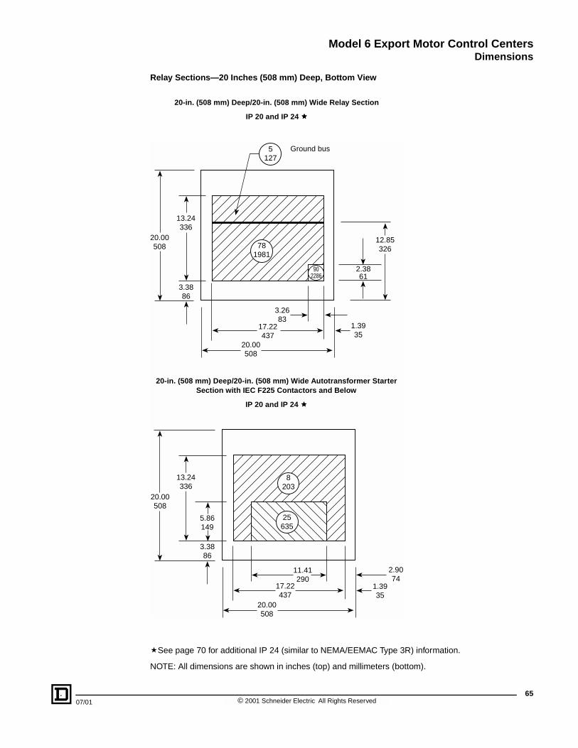
Model 6 Export Motor Control CentersDimensions
07/01
Relay Sections—20 Inches (508 mm) Deep, Bottom View
�See page 70 for additional IP 24 (similar to NEMA/EEMAC Type 3R) information.
NOTE: All dimensions are shown in inches (top) and millimeters (bottom).
17.22437
3.3886
20.00508
13.24336
1.3935
12.85326
Ground bus
902286
2.3861
3.2683
8203
11.41290
25635
5.86149
2.9074
5127
781981
20.00508
20.00508
20.00508
13.24336
3.3886
17.22437
1.3935
20-in. (508 mm) Deep/20-in. (508 mm) Wide Autotransformer Starter Section with IEC F225 Contactors and Below
IP 20 and IP 24 ����
20-in. (508 mm) Deep/20-in. (508 mm) Wide Relay Section
IP 20 and IP 24 ����
65© 2001 Schneider Electric All Rights Reserved

Model 6 Export Motor Control CentersDimensions
66
NOTE: All dimensions are shown in inches (top) and millimeters (bottom).
15.46393
4.07103
20.00508
11.86301
2.2758
12.85326
Ground bus
2.3861
11.41290
2.0251
5127
781981
902286
8203
25635
20.00508
20.00508
20.00508
11.86301
4.07103
5.86149
2.3861
15.46393
2.2758
20 -in. (508 mm) Deep/20-in. (508 mm) Wide Relay Section
IP 52
20-in. (508 mm) Deep/20-in. (508 mm) Wide Autotransformer Starter Section with IEC F225 Contactors and Below
IP 52
© 2001 Schneider Electric All Rights Reserved 07/01

Model 6 Export Motor Control CentersDimensions
07/01
Main/Branch Devices and Relay Sections—20 Inches (508 mm) Deep, Bottom View
� See page 70 for additional IP 24 (similar to NEMA/EEMAC Type 3R) information.
� When the section contains a main, branch feeder, and a switch, the vertical clearance becomes approximately 30 inches (762 mm).
NOTE: All dimensions are shown in inches (top) and millimeters (bottom).
22.22559
25.00635
3.3886
13.24336
1.3935
12.85326
Ground bus
2.3861
8.26210
5127
781981
902286
20.00508
20.46520
25.00635
4.07103
11.86301
2.2758
12.85326
Ground bus
1.6943
7.38187
5127
781981
902286
20.00508
800–1200 A Main, Branch, or 20-in. (508 mm) Deep/25-in. (635 mm) Wide Relay Section ����
IP 20 and 24 ����
800–1200A Main, Branch, or 20-in. (508 mm) Deep/25-in (625 mm) Wide Relay Section ����
IP 52
67© 2001 Schneider Electric All Rights Reserved

Model 6 Export Motor Control CentersDimensions
68
� See page 70 for additional IP 24 (similar to NEMA/EEMAC Type 3R) information.
� When the section contains a main, branch feeder, and a switch, the vertical clearance becomes approximately 30 inches (762 mm).
NOTE: All dimensions are shown in inches (top) and millimeters (bottom).
27.22691
30.00762
2.3861
3.3886
13.24336
1.3935
8.26210
1.4838
5.37136
12.85326
Ground bus5127
781981
902286
20.00508
26660 20.00
508
13.24336
3.3886
30.00762
1800–2000 A Main, Branch, or 20-in. (508 mm) Deep/30-in. (762 mm) Wide Relay Section ����
IP 20 and IP 24 ����
20-in. (508 mm) Deep Autotransformer Starter Section with IEC F265 Contactors and Above
IP 20 and IP 24 ����
© 2001 Schneider Electric All Rights Reserved 07/01

Model 6 Export Motor Control CentersDimensions
07/01
� When the section contains a main, branch feeder, and a switch, the vertical clearance becomes approximately 30 inches (762 mm).
NOTE: All dimensions are shown in inches (top) and millimeters (bottom).
25.46647
1.6943
4.07103
11.86301
2.2758
7.38187
2.2858
3.8197
12.85326
Ground bus5127
781981
902286
20.00508
20.00508
26660
30.00762
30.00762
4.07103
11.86301
600–1200 A Main, Branch, or 20-in. (508 mm) Deep/30-in. (762 mm) Wide Relay Section ����
IP 52
20-in. (508 mm) Deep SC/B Autotransformer Starter Section with IEC F265 Contactors and Above
IP 52
69© 2001 Schneider Electric All Rights Reserved

Model 6 Export Motor Control CentersDimensions
70
Additional Conduit Entry Information for IP 24 (Similar to NEMA/EEMAC Type 3R) Enclosures
NOTE: All dimensions are shown in inches (top) and millimeters (bottom).
Conduit entry area is the same as IP 20 enclosure.
Floor planconduit entry
6152
Front11.3287
0.38
Standardsection depth15 or 20 in.
381 or 508 mm
Conduit entry area is the same as IP 20 enclosure.
Conduit entry area is the same as IP 20 enclosure.
Standard Section Width20, 25, or 30 in.
508, 635, or 762 mm
Standard Section Width20, 25, or 30 in.
508, 635, or 762 mm
Standard Section Width20, 25, or 30 in.
508, 635, or 762 mm
Combined width of sections, plus 6 in. (152 mm) per shipping split
© 2001 Schneider Electric All Rights Reserved 07/01

Model 6 Export Motor Control CentersDimensions
07/01
Standard Sections—15 Inches (381 mm) Deep, Top View
� A 90-in. (2286 mm) vertical wireway area is not available for a 1200 A main lug compartment.
NOTE: All dimensions are shown in inches (top) and millimeters (bottom).
15.00381
17.22437
12305
4.14105
3.26831.62
41
11.76299
1.3935
902286
20.00508
20.00508
12305
902286
15.00381
11.76299
1.6241 17.22
437
3.2683
4.14105
1.3935
20-in. (508 mm) Wide/15-in. (381 mm) Deep Standard Section
IP 20 and IP 52
20-in. (508 mm) Wide/15-in. (381 mm) Deep Standard Section with Top-Located Main Lug Compartment ����
IP 20 and IP 52
71© 2001 Schneider Electric All Rights Reserved

Model 6 Export Motor Control CentersDimensions
72
� A 90-in. (2286 mm) vertical wireway area is not available for a 1200 A main lug compartment.
NOTE: All dimensions are shown in inches (top) and millimeters (bottom).
22.22564
8.26210
25.00635
6.25159
15.00381
12305
902286
15.00381
12305
902286
4.14105
1.6241
11.76299
1.3935
1.6241
11.76299
1.3935
22.22564
25.00635
8.26210
25-in. (635 mm) Wide/15-in. (381 mm) Deep Standard Section with 90-in. (2286) Vertical Wireway
IP 20 and IP 52
25-in. (635 mm) Wide/15-in. (381 mm) Deep Standard Section with Top-Located Main Lug Compartment ����
IP 20 and IP 52
© 2001 Schneider Electric All Rights Reserved 07/01
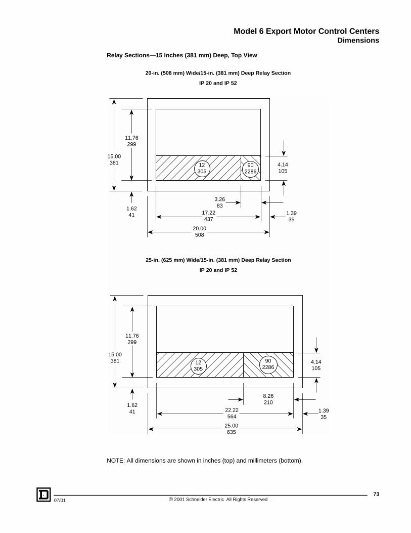
Model 6 Export Motor Control CentersDimensions
07/01
Relay Sections—15 Inches (381 mm) Deep, Top View
NOTE: All dimensions are shown in inches (top) and millimeters (bottom).
17.22437
3.2683
20.00508
22.22564
15.00381 12
30590
22864.14105
1.6241
11.76299
1.3935
25.00635
8.26210
1.3935
12305
902286
4.14105
15.00381
11.76299
1.6241
25-in. (625 mm) Wide/15-in. (381 mm) Deep Relay Section
IP 20 and IP 52
20-in. (508 mm) Wide/15-in. (381 mm) Deep Relay Section
IP 20 and IP 52
73© 2001 Schneider Electric All Rights Reserved
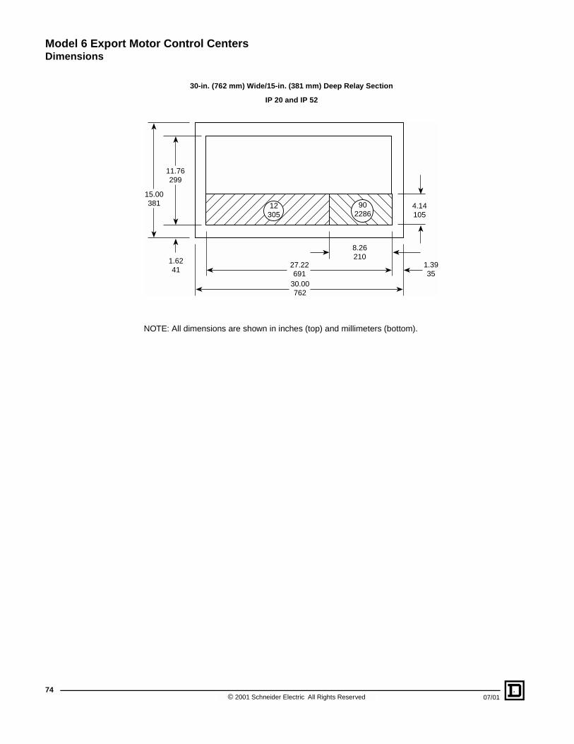
Model 6 Export Motor Control CentersDimensions
74
NOTE: All dimensions are shown in inches (top) and millimeters (bottom).
27.22691
30.00762
15.00381 12
30590
2286
1.6241
11.76299
1.3935
8.26210
4.14105
30-in. (762 mm) Wide/15-in. (381 mm) Deep Relay Section
IP 20 and IP 52
© 2001 Schneider Electric All Rights Reserved 07/01
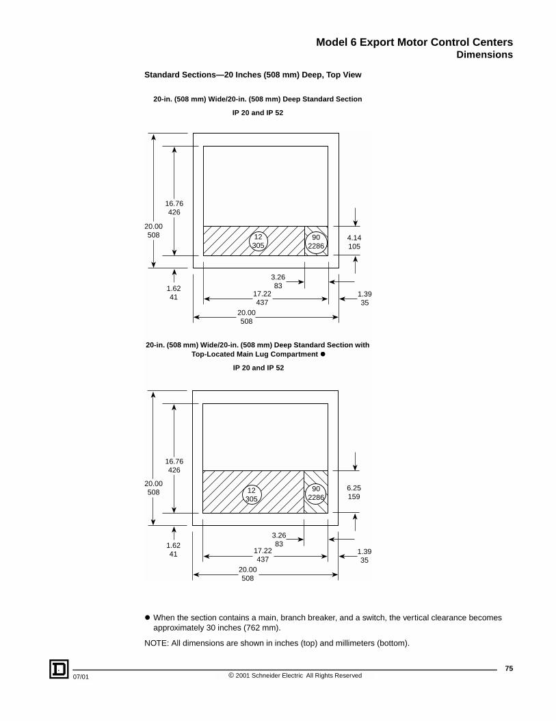
Model 6 Export Motor Control CentersDimensions
07/01
Standard Sections—20 Inches (508 mm) Deep, Top View
� When the section contains a main, branch breaker, and a switch, the vertical clearance becomes approximately 30 inches (762 mm).
NOTE: All dimensions are shown in inches (top) and millimeters (bottom).
16.76426
6.25159
17.22437
3.2683
20.00508
12305
902286
4.14105
1.6241 1.39
35
20.00508
16.76426
17.22437
3.2683
20.00508
12305
902286
1.6241 1.39
35
20.00508
20-in. (508 mm) Wide/20-in. (508 mm) Deep Standard Section
IP 20 and IP 52
20-in. (508 mm) Wide/20-in. (508 mm) Deep Standard Section with Top-Located Main Lug Compartment ����
IP 20 and IP 52
75© 2001 Schneider Electric All Rights Reserved

Model 6 Export Motor Control CentersDimensions
76
� When the section contains a main, branch breaker, and a switch, the vertical clearance becomes approximately 30 inches (762 mm).
NOTE: All dimensions are shown in inches (top) and millimeters (bottom).
20.00508
22.22564
25.00635
16.76426
6.25159
12305
902286
4.14105
1.6241
11.76299
8.26210
1.3935
12305
902286
1.6241 1.39
35
20.00508
22.22564
25.00635
8.26210
25-in. (635 mm) Wide/20-in. (508 mm) Deep Standard Section with 9-in. (229 mm) Vertical Wireway
IP 20 and IP 52
25-in. (835 mm) Wide/20-in. (508 mm) Deep Section with Top-Located Main Lug Compartment � and 9-in. (229 mm) Vertical Wireway
IP 20 and IP 52
© 2001 Schneider Electric All Rights Reserved 07/01

Model 6 Export Motor Control CentersDimensions
07/01
Relay Sections—20 Inches (508 mm) Deep, Top View
� When the section contains a main, branch breaker, and a switch, the vertical clearance becomes approximately 30 inches (762 mm).
NOTE: All dimensions are shown in inches (top) and millimeters (bottom).
16.76426
6.25159
17.22437
3.2683
20.00508 12
30590
22864.14105
1.6241 1.39
3520.00508
16.76426
20.00508
12305
902286
1.6241 1.39
3522.22564
25.00635
8.26210
20-in. (508 mm) Wide/20-in. (508 mm) Deep Relay Section ����
25-in. (635 mm) Wide/20-in. (508 mm) Deep Relay Section ����
77© 2001 Schneider Electric All Rights Reserved
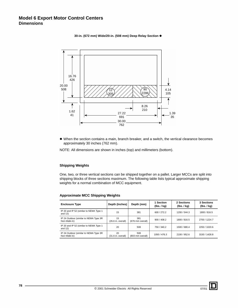
Model 6 Export Motor Control CentersDimensions
78
� When the section contains a main, branch breaker, and a switch, the vertical clearance becomes approximately 30 inches (762 mm).
NOTE: All dimensions are shown in inches (top) and millimeters (bottom).
Shipping Weights
One, two, or three vertical sections can be shipped together on a pallet. Larger MCCs are split into shipping blocks of three sections maximum. The following table lists typical approximate shipping weights for a normal combination of MCC equipment.
Approximate MCC Shipping Weights
Enclosure Type Depth (Inches) Depth (mm)1 Section (lbs. / kg)
2 Sections (lbs. / kg)
3 Sections (lbs. / kg)
IP 20 and IP 52 (similar to NEMA Type 1 and 12)
15 381 600 / 272.2 1200 / 544.3 1800 / 816.5
IP 24 Outdoor (similar to NEMA Type 3R Non-Walk-In)
15(26.6 in. overall)
381(676 mm overall)
900 / 408.2 1800 / 816.5 2700 / 1224.7
IP 20 and IP 52 (similar to NEMA Type 1 and 12)
20 508 750 / 340.2 1500 / 680.4 2250 / 1020.6
IP 24 Outdoor (similar to NEMA Type 3R Non-Walk-In)
20(31.6 in. overall)
508(803 mm overall)
1050 / 476.3 2100 / 952.6 3150 / 1428.8
27.22691
30.00762
16.76426
20.00508 12
30590
22864.14105
1.6241
1.3935
8.26210
30-in. (672 mm) Wide/20-in. (508 mm) Deep Relay Section ����
© 2001 Schneider Electric All Rights Reserved 07/01

Model 6 Export Motor Control CentersSample Specifications
07/01
SECTION CONTENTS
SECTION 5—SAMPLE SPECIFICATIONS . . . . . . . . . . . . . . . . . . . . . . . . . . . . . . . . . . . . . . . . . . . . 80Submittals . . . . . . . . . . . . . . . . . . . . . . . . . . . . . . . . . . . . . . . . . . . . . . . . . . . . . . . . . . . . . . . . . . 80
Regulatory Requirements . . . . . . . . . . . . . . . . . . . . . . . . . . . . . . . . . . . . . . . . . . . . . . . . . . . . . . 80Packing/Shipping . . . . . . . . . . . . . . . . . . . . . . . . . . . . . . . . . . . . . . . . . . . . . . . . . . . . . . . . . . . . . 80Storage . . . . . . . . . . . . . . . . . . . . . . . . . . . . . . . . . . . . . . . . . . . . . . . . . . . . . . . . . . . . . . . . . . . . 80
Warranty . . . . . . . . . . . . . . . . . . . . . . . . . . . . . . . . . . . . . . . . . . . . . . . . . . . . . . . . . . . . . . . . . . . 80Manufacturers . . . . . . . . . . . . . . . . . . . . . . . . . . . . . . . . . . . . . . . . . . . . . . . . . . . . . . . . . . . . . . . 80Materials . . . . . . . . . . . . . . . . . . . . . . . . . . . . . . . . . . . . . . . . . . . . . . . . . . . . . . . . . . . . . . . . . . . 80
MCC Finish . . . . . . . . . . . . . . . . . . . . . . . . . . . . . . . . . . . . . . . . . . . . . . . . . . . . . . . . . . . . . . . . . 81Structures . . . . . . . . . . . . . . . . . . . . . . . . . . . . . . . . . . . . . . . . . . . . . . . . . . . . . . . . . . . . . . . . . . 81Wireways . . . . . . . . . . . . . . . . . . . . . . . . . . . . . . . . . . . . . . . . . . . . . . . . . . . . . . . . . . . . . . . . . . . 81
Barriers . . . . . . . . . . . . . . . . . . . . . . . . . . . . . . . . . . . . . . . . . . . . . . . . . . . . . . . . . . . . . . . . . . . . 82Bussing . . . . . . . . . . . . . . . . . . . . . . . . . . . . . . . . . . . . . . . . . . . . . . . . . . . . . . . . . . . . . . . . . . . . 82Typical Unit Construction . . . . . . . . . . . . . . . . . . . . . . . . . . . . . . . . . . . . . . . . . . . . . . . . . . . . . . . 83
Components for Typical Units . . . . . . . . . . . . . . . . . . . . . . . . . . . . . . . . . . . . . . . . . . . . . . . . . . . 83Six-Inch (152 mm) Unit Construction . . . . . . . . . . . . . . . . . . . . . . . . . . . . . . . . . . . . . . . . . . . . . . 84Components for Six-Inch (152 mm) Units . . . . . . . . . . . . . . . . . . . . . . . . . . . . . . . . . . . . . . . . . . 85
Quality Control . . . . . . . . . . . . . . . . . . . . . . . . . . . . . . . . . . . . . . . . . . . . . . . . . . . . . . . . . . . . . . . 86Location . . . . . . . . . . . . . . . . . . . . . . . . . . . . . . . . . . . . . . . . . . . . . . . . . . . . . . . . . . . . . . . . . . . . 86
79© 2001 Schneider Electric All Rights Reserved

Model 6 Export Motor Control CentersSample Specifications
80
SECTION 5—SAMPLE SPECIFICATIONS
This section includes requirements for an IEC-based motor control center (MCC) and all required control devices as shown on the drawings and specified to be part of the MCC equipment. The MCC shall be [380V, 3-Phase, 3-Wire, 50Hz] [380V, 3-Phase, 4-Wire, 50Hz] [415V, 3-Phase, 3-wire, 50Hz] [400V, 3-Phase, 3-Wire, 50Hz] [440V, 3-Phase, 3-Wire, 50Hz] [480V, 3-Phase, 3-Wire, 60 Hz] [480V, 3-Phase, 4-Wire, 60Hz] [220V, 3-Phase, 3-Wire, 50Hz] [240V, 3-Phase, 3-Wire, 50Hz] [660V, 3-Phase, 3-Wire, 50Hz] [660V, 3-Phase, 4-Wire, 50Hz] [690v, 3-Phase, 3-Wire, 50Hz].
Submittals
Submit with the delivery of the MCC an Installation and Maintenance Manual and one (1) copy of the manufacturer's drawings per shipping block.
Regulatory Requirements
The MCC must conform to IEC Standard 60439-1 (fourth edition), IEC 60947-3 (1999), IEC 60947-4 (1990), and IEC 60529 (1989). The MCC must be manufactured in an ISO 9001 certified facility.
Packing/Shipping
The MCC shall be separated into shipping blocks no more than three vertical sections each. Shipping blocks shall be shipped on their sides to permit easier handling at the jobsite. Each shipping block shall include a removable lifting angle, which will allow an easy means of attaching an overhead crane or other suitable lifting equipment.
Storage
If the MCC cannot be placed into service reasonably soon after its receipt, store it in a clean, dry and ventilated building free from temperature extremes. Acceptable storage temperatures are from 32° F (0° C) to 104° F (40° C) .
Warranty
The MCC shall be warranted to be free from defects in materials and workmanship for a period of eighteen (18) months from the date of invoice from the manufacturer or authorized sales channel.
Manufacturers
A. Shall be Schneider Electric/Square D Company or equal.
B. Additions to existing MCCs shall be the same as the original manufacturer.
Materials
A. Steel material shall comply with UL 845 and CSA requirements.
B. Each MCC shall consist of one or more vertical sections of heavy gauge steel bolted together to form a rigid, free-standing assembly. Removable 7-gauge structural steel lifting angles shall be mounted along the full width of the MCC lineup at the top. Removable 7-gauge bottom channel sills shall be mounted underneath the front and rear of the vertical sections, extending the full width of the lineup. Vertical sections made of welded side-frame assembly shall be formed from a minimum of 12-gauge steel. Internal reinforcement structural parts shall be of 12- and 14-gauge steel to provide a strong, rigid assembly. The entire assembly shall be constructed and packaged to withstand normal stresses included in transit and during installation.
© 2001 Schneider Electric All Rights Reserved 07/01

Model 6 Export Motor Control CentersSample Specifications
07/01
MCC Finish
A. All steel parts shall be provided with UL and CSA listed acrylic/alkyd baked enamel paint finish, except plated parts used for ground connections. All painted parts shall undergo a multi-stage treatment process, followed by the finishing paint coat.
B. Pre-treatment shall include:
1. Hot alkaline cleaner to remove grease and oil.
2. Iron phosphate treatment to improve adhesion and corrosion resistance.
C. The paint shall be applied using an electro-deposition process to ensure a uniform paint coat with high adhesion.
D. The standard paint finish shall be tested to UL 50 per ASTM B117 (5% ASTM Salt Spray) with no greater than 0.125 in (3 mm) loss of paint from a scribed line.
E. Paint color shall be #49 medium light gray per ANSI standard Z55.1-967 (60-70 gloss) on all surfaces unless specified otherwise. Control station plates and escutcheon plates shall be painted a contrasting gray. All unit interior saddles shall be painted white for better visibility inside the unit.
Structures
A. Structures shall be totally enclosed, dead-front, freestanding assemblies. Structures shall be capable of being bolted together to form a single assembly.
B. The overall height of the MCC shall not exceed 90 in. (2286 mm) (not including base channel or lifting angle). Base channels of 1.5 in. (38 mm) in height, and lifting angles of 3 in. (76 mm) in height shall be removable. The total width of one section shall be 20 in. (508 mm). [Widths of 25 in. (630 mm), 30 in. (760 mm), and 35 in. (890 mm) can be used for larger devices].
C. Structures shall be IEC 60529 classification [ IP 20 (indoor general purpose) ] [ IP 52 (indoor industrial duty) ] [ IP 24 outdoor non-walk-in (rainproof)].
D. Each 20 in.- (508 mm) wide standard section shall have all the necessary hardware and bussing for modular plug-in units to be added and moved around. All unused space shall be covered by hinged blank doors and equipped to accept future units. Vertical bus openings shall be covered by manual bus shutters.
E. Each section shall include a top plate (single piece or two-piece) and shall also include a bottom plate. Top and bottom plates shall be removable for ease in cutting conduit entry openings.
Wireways
A. Structures shall contain a minimum 12 in.- (305 mm) high horizontal wireway at the top of each section and a minimum 6 in.- (152 mm) high horizontal wireway at the bottom of each section. These wireways shall run the full length of the MCC to allow room for power and control cables to connect between units in different sections.
A. A full-depth vertical wireway shall be provided in each MCC section that accepts modular plug-in units. The vertical wireway shall connect with both the top and bottom horizontal wireways and shall be isolated from unit interiors by a full-height barrier. The vertical wireway shall be 4 in. (102 mm) wide minimum with a separate hinged door. There should be a minimum of 4,000 in.3 (65, 548 cm3) of cabling space available. Access to the wireways shall not require opening control unit doors. Structures that house a single, full-section control unit are not required to have vertical wireways. Those control units must open directly into the MCC horizontal wireways.
81© 2001 Schneider Electric All Rights Reserved

Model 6 Export Motor Control CentersSample Specifications
82
Barriers
A. All power bussing and splice connections shall be isolated from the unit compartments and the wireways. The horizontal bus shall be mounted onto a glass-filled polyester support assembly that braces the bus against the forces generated during a short circuit. The horizontal bus shall be isolated from the top horizontal wireway by a two-piece plastic barrier. This barrier shall be removable to allow access to the bus and connections for maintenance.
B. The vertical bus shall be housed in a molded glass-filled polyester support that provides bus insulation and braces the bus against the forces generated during a short circuit. These supports shall have openings every 3 in. (75 mm) for unit stab-on connections. Each opening shall be provided with a manual shutter to close off the stab opening. These shutters shall be attached to the structure so that when they are removed (to allow a stab connection) they are retained in the structure and are readily accessible for use should a plug-in unit be removed from the MCC.
C. Barriers shall be provided in the vertical structure and unit designs to prevent the contact of any energized bus or terminal by a fishtape inserted through the conduit or wireway areas.
D. MCCs shall contain a system of internal partitions to meet form of separation 4a per IEC 60439-1.
Bussing
A. All bussing and connectors shall be [ tin-plated ] [ silver-plated ] copper .
B. The main horizontal bus shall be rated at [600 A] [800 A] [1200 A] [1600 A] [2000 A] [2500 A] continuous and shall extend the full length of the MCC. Bus shall be type tested assemblies (TTA) for temperature and short circuit withstand strength per IEC 60439-1. Provisions shall be provided for splicing additional sections onto either end of the MCC.
C. The horizontal bus splice bars shall be pre-assembled into a captive bus stack. This bus stack is installed into the end of the MCC power bus to allow the installation of additional sections. The main bus splice shall utilize four bolts, two on each side of the bus split, for each phase. Additional bolts must not be required when splicing higher amperage bus. The splice bolts shall secure to self-clenching nuts installed in the bus assembly. It shall be possible to maintain any bus connection with a single tool. “Nut and bolt” bus connections to the power bus shall not be permitted.
D. Each section that accepts plug-in units shall be provided with a vertical bus for distributing power from the main bus to the individual plug-in starter units. This bus shall be of the same material and plating as the main bus, and shall be rated at 600 A continuous. The vertical bus shall be connected directly to the horizontal bus stack without the use of risers or other intervening connectors. It shall be possible to maintain the vertical to horizontal bus connection with a single tool. “Nut and bolt” bus connections to the power bus shall not be permitted.
E. A tin-plated copper ground bus shall be provided that runs the entire length of the MCC. The ground bus shall consist of two (2) 0.25 in. (6.0 mm) x 1.0 in. (25 mm) bars and be rated for 600 amps. A compression lug shall be provided in the MCC for a 4/0-250 kcmil ground cable. The ground bus shall be provided with (6) 0.38 in. (10 mm) holes for each vertical section to accept customer-supplied ground lugs for any loads requiring a ground conductor.
F. Each vertical section with vertical power bus shall have a tin-plated copper vertical ground bus that is connected to the horizontal ground bus. This vertical ground bus shall be installed so that the plug-in units engage the ground bus prior to engagement of the power stabs and shall disengage only after the power stabs are disconnected upon removal of the plug-in unit.
G. The system shall be rated for an available short circuit capacity of [22,000] [42,000] [50,000] [65,000] [70,000] rms amperes, and be rated with a short-time current (ICW) of [22,000] [42,0000] [50,000] [65,000] [70,000] rms amperes for 1 second.
© 2001 Schneider Electric All Rights Reserved 07/01

Model 6 Export Motor Control CentersSample Specifications
07/01
Typical Unit Construction
A. All surfaces (back, side, and bottom plates) of the unit interior shall be painted white.
B. Units with circuit breaker disconnects through a 600 A frame shall connect to the vertical bus through a spring-reinforced stab-on connector. Units with larger disconnects shall be connected directly to the main horizontal bus with appropriately sized cable or riser bus. Stabs on all plug-on units shall be solidly bussed to the unit disconnect. Cabled stab assemblies are not permitted.
C. All conducting parts on the line side of the unit disconnect shall be shrouded by a suitable insulating material to prevent accidental contact with those parts.
D. Unit mounting shelves shall include hanger brackets to support the unit weight during installation and removal. All plug-on units shall use a twin-handle cam lever located at the top of the bucket to rack in and out the plug-on unit. The cam lever shall work in conjunction with the hanger brackets to ensure positive stab alignment.
E. A handle operator must be provided on the unit door for each disconnect. With the unit stabs engaged onto the vertical phase bus and the unit door closed, the handle mechanism shall allow complete ON/OFF control of the unit disconnect with clear indication of the disconnect’s status. All circuit breaker operators shall include a separate TRIP position to clearly indicate a circuit breaker trip condition. It shall be possible to reset a tripped circuit breaker without opening the control unit door.
F. A mechanical interlock shall prevent the operator from opening the unit door when the disconnect is in the ON position. It shall be possible for authorized personnel to defeat these interlocks.
G. A non-defeatable interlock shall be provided between the handle operator and the cam lever to prevent installing or removing a plug-on unit unless the disconnect is in the OFF position.
H. The plug-in unit shall have a grounded stab-on connector which engages the vertical ground bus prior to, and releases after, the power bus stab-on connectors.
I. Provisions shall be provided for locking all disconnects in the OFF position with up to three padlocks.
J. Unit construction shall combine with the vertical wireway isolation barrier to provide a fully compartmentalized design.
K. Internal degree of protection shall be IP 20 between units.
Components for Typical Units
A. Combination Starters
1. All combination starters shall utilize a unit disconnect as specified in the previous section. Magnetic starters shall be furnished in all combination starter units. All starters shall utilize IEC contactors rated for AC-3 duty. Starters shall be provided with a three-pole, external manual reset and [ambient compensated bimetallic] [solid state] overload relay units.
2. When provided, control circuit transformers shall include two primary protection fuses and one secondary fuse (in the non-ground secondary conductor). The transformer shall be sized to accommodate the contactor(s) and all connected control circuit loads. The transformer rating shall be fully visible from the front when the unit door is opened.
3. When a unit control circuit transformer is not provided, the disconnect shall include an electrical interlock for disconnecting externally powered control circuits.
4. Auxiliary control circuit interlocks shall be provided where indicated. Auxiliary interlocks shall be field convertible to normally open or normally closed operation.
5. Starters shall be mounted directly adjacent to the wireway so that power wiring (motor leads) shall connect directly to the starter terminals without the use of interposing terminals. Large starters shall be arranged so that power wiring may exit through the bottom of the starter cubical without entering the vertical wireway.
83© 2001 Schneider Electric All Rights Reserved

Model 6 Export Motor Control CentersSample Specifications
84
B. Terminal Blocks
1. All starter units shall be provided with unit control terminal blocks.
2. Terminal blocks shall be IEC type 600 volt, box lug type, and rated at 30 amps. All current carrying parts shall be tin-plated. Terminals shall be accessible from inside the unit when the unit door is opened. Terminal blocks shall be DIN rail-mounted and secured to the unit bottom plate. The terminals used for field connections shall face forward so they can be wired without removing the unit or any of its components.
C. Nameplates
1. Each MCC and unit compartment shall have engraved phenolic nameplates. They shall be gray background with white letters, measuring a minimum of 1.5 in (38 mm) H x 6.25 in. (159 mm) W total outside dimensions.
Six-Inch (152 mm) Unit Construction
A. Units with circuit breaker disconnects through 100 A frame shall connect to the vertical bus through a spring-reinforced stab-on connector. Stabs on all plug-on units shall be cable connected to the unit disconnect.
B. All conducting parts on the line side of the unit disconnect shall be shrouded by a suitable insulating material.
C. Unit mounting shelves shall include hanger brackets to support the unit weight during installation and removal. All six-inch plug-on units shall be installable without the assistance of a camming device so as to allow maximum accessibility with the unit installed.
D. A cast metal handle operator must be provided on each disconnect. With the unit stabs engaged into the vertical phase bus and the unit door closed, the handle mechanism shall allow complete ON/OFF control of the unit disconnect with clear indication of the disconnect’s status. All circuit breaker operators shall include a separate TRIP position to clearly indicate a circuit breaker trip condition. It shall be possible to reset a tripped circuit breaker without opening the control unit door.
1. A mechanical interlock shall prevent an operator from opening the unit door when the disconnect is in the ON position. Another mechanical interlock shall prevent an operator from placing the disconnect in the ON position while the door is open. It shall be possible for authorized personnel to defeat these interlocks.
2. A non-defeatable interlock shall be provided between the handle operator and the structure to prevent installing or removing a plug-on unit unless the disconnect is in the OFF position. The plug-on unit shall have a grounded stab-on connector which engages the vertical ground bus prior to, and releases after, the power bus stab-on connectors.
E. Provisions shall be made for locking all disconnects in the OFF position with up to three padlocks.
F. Handle mechanisms shall be located on the bottom left side of the unit and operate horizontally to encourage operators to stand to the left of the unit being switched.
G. Unit construction shall combine with the vertical wireway isolation barrier to provide a fully compartmentalized design.
H. Up to a maximum of twelve six-inch (152 mm) units can be installed per vertical section without placement restrictions in new or existing applications.
© 2001 Schneider Electric All Rights Reserved 07/01

Model 6 Export Motor Control CentersSample Specifications
07/01
Components for Six-Inch (152 mm) Units
A. Six-Inch (152 mm) Combination Starters
1. All six-inch (152 mm) combination starters shall use a unit disconnect as specified in the previous article. All starters shall use IEC contactors rated for AC-3 duty. Starter units shall be provided with a 3-pole, external manual reset and ambient compensated bimetallic motor overload protection.
2. When provided, control circuit transformers shall include two primary protection fuses and one secondary fuse (in the non-ground secondary conductor.) The transformer shall be sized to accommodate the contactor(s) and all connected control circuit loads.
3. When a unit control circuit transformer is not provided, the disconnect shall include an electrical interlock for disconnecting externally powered control circuits.
4. Auxiliary control circuit interlocks shall be provided where indicated.
5. Starters shall be mounted directly adjacent to the wireway so that power wiring (motor leads) will connect directly to the starter terminals.
B. Terminal Blocks for Six-Inch (152 mm) Units
1. All starter units shall be provided with unit control terminal blocks.
2. Terminal blocks shall be pull-apart type, 250 V, and rated for 10 amperes. All current-carrying parts shall be tin-plated. Terminals shall be accessible from inside the unit when the unit door is opened. The stationary portion of the terminal block shall be used for factory connections and will remain attached to the unit when the portion used for field connections is removed. The terminals used for field connections shall be accessible so they can be wired without removing the unit or any of its components.
C. Engraved phenolic nameplates shall be provided for each MCC and unit compartment. Each nameplate shall have a gray background, white lettering, and measure a minimum of 1.5 in. H x 6.25 in. W (38 mm H x 150 mm W) total outside dimensions.
D. Each unit to be provided with a control panel for up to four pilot devices [Pilot device control panel can be deleted if no local unit pilot devices are required.] Control panel to be removable by loosening two semi-captive fasteners for customer access.
85© 2001 Schneider Electric All Rights Reserved

Model 6 Export Motor Control CentersSample Specifications
86
Quality Control
A. The entire MCC shall go through a quality inspection before shipment. This inspection will include:
1. Physical Inspection of:
a. Structure
b. Electrical conductors, including:
1) bussing
2) general wiring
3) units
2. Electrical Tests
a. General electrical tests include:
1) power circuit phasing
2) control circuit wiring
3) instrument transformers
4) meters
5) ground fault system
6) device electrical operation
b. AC dielectric tests shall be performed on the power circuit
3. Markings/Labels, include:
a. instructional type
b. inspector's stamps
c. CE mark (if requested)
B. The manufacturer shall use integral quality control checks throughout the manufacturing process to ensure that the MCC meets operating specifications.
Location
A. Motor control centers are not to be placed in hazardous locations. The area chosen shall be well ventilated and totally free from humidity, dust and dirt. The temperature of the area shall be no less than 32° F (0° C) and no greater than 104° F (40° C). For indoor locations, protection must be provided to prevent moisture entering the enclosure .
B. Motor control centers shall be located in an area with a minimum of 3 ft. (915 mm) of free space in front of front-of-board construction. An additional 3 ft. (915 mm) should be allowed in the rear of back-to-back construction. This free space will give adequate room to remove and install units. A minimum of 0.5 in. (13 mm) space should be provided between the back of front-of-board MCCs and a wall, 6 in. (152 mm) required for damp locations.
C. The MCCs shall be assembled in the factory on a smooth level surface so that all sections are properly aligned. A similar smooth and level surface shall be provided for installation. An uneven foundation will cause misalignment of shipping blocks, units, and doors. The surface under a MCC shall be of a non-combustible material unless bottom plates are installed in each vertical section.
© 2001 Schneider Electric All Rights Reserved 07/01

Model 6 Export Motor Control CentersAppendix
07/01
SECTION CONTENTS
APPENDIX . . . . . . . . . . . . . . . . . . . . . . . . . . . . . . . . . . . . . . . . . . . . . . . . . . . . . . . . . . . . . . . . . . . . . 88Parts Lists . . . . . . . . . . . . . . . . . . . . . . . . . . . . . . . . . . . . . . . . . . . . . . . . . . . . . . . . . . . . . . . . . . 88
Main and Branch Circuit Breakers . . . . . . . . . . . . . . . . . . . . . . . . . . . . . . . . . . . . . . . . . . . . 88Starter Unit Circuit Breakers . . . . . . . . . . . . . . . . . . . . . . . . . . . . . . . . . . . . . . . . . . . . . . . . . 89Starter Unit Contactors . . . . . . . . . . . . . . . . . . . . . . . . . . . . . . . . . . . . . . . . . . . . . . . . . . . . . 91
Starter Unit Overload Relays . . . . . . . . . . . . . . . . . . . . . . . . . . . . . . . . . . . . . . . . . . . . . . . . 92Items Subject to Customer Agreement . . . . . . . . . . . . . . . . . . . . . . . . . . . . . . . . . . . . . . . . . . . . 94
87© 2001 Schneider Electric All Rights Reserved
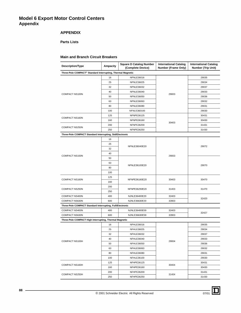
Model 6 Export Motor Control CentersAppendix
88
APPENDIX
Parts Lists
Main and Branch Circuit Breakers
Description/Type AmpacitySquare D Catalog Number
(Complete Device)International Catalog Number (Frame Only)
International Catalog Number (Trip Unit)
Three-Pole COMPACT® Standard Interrupting, Thermal Magnetic
COMPACT NS100N
16 NFNLE36016
29003
29035
25 NFNLE36025 29034
32 NFNLE36032 29037
40 NFNLE36040 29033
50 NFNLE36050 29036
63 NFNLE36063 29032
80 NFNLE36080 29031
100 NFNLE360100 29030
COMPACT NS160N125 NFNPE36125
30403
30431
160 NFNPE36160 30430
COMPACT NS250N200 NFNPE36200 31431
250 NFNPE36250 31430
Three-Pole COMPACT Standard Interrupting, Std/Electronic
COMPACT NS100N
16
NFNLE36040E20
29003
2907225
32
40
50
NFNLE36100E20 2907063
80
100
COMPACT NS160N125
NFNPE36160E20 30403 30470160
COMPACT NS250N200
NFNPE36250E20 31403 31470250
COMPACT NS400N 400 NJNLE36400E20 3240332420
COMPACT NS630N 600 NJNLE36630E20 32803
Three-Pole COMPACT Standard Interrupting, Full/Electronic
COMPACT NS400N 400 NJNLE36400E59 3240332427
COMPACT NS630N 600 NJNLE36630E59 32803
Three-Pole COMPACT High Interrupting, Thermal Magnetic
COMPACT NS100H
16 NFHLE36016
29004
29035
25 NFHLE36025 29034
32 NFHLE36032 29037
40 NFHLE36040 29033
50 NFHLE36050 29036
63 NFHLE36063 29032
80 NFHLE36080 29031
100 NFHLE36100 29030
COMPACT NS160H125 NFHPE36125
3040430431
160 NFHPE36160 30430
COMPACT NS250H200 NFHPE36200
3140431431
250 NFHPE36250 31430
© 2001 Schneider Electric All Rights Reserved 07/01

Model 6 Export Motor Control CentersAppendix
07/01
Three-Pole COMPACT High Interrupting, Std/Electronic
COMPACT NS100H
16
NFHLE36040E20
29004
2907225
32
40
50
NFHLE36100E20 2907063
80
100
COMPACT NS160H125
NFHPE36160E20 30404 30470160
COMPACT NS250H200
NFHPE36250E20 31404 31470250
COMPACT NS400H 400 NJHLE36400E59 3240432420
COMPACT NS630H 600 NJHLE36630E59 32804
Three-Pole COMPACT High Interrupting, Full/Electronic
COMPACT NS400H 400 NJHLE36400E59 3240432427
COMPACT NS630H 600 NJHLE36630E59 32803
Starter Unit Circuit Breakers
Description/Type AmpacitySquare D Catalog Number
(Complete Device)International Catalog Number (Frame Only)
International Catalog Number (Trip Unit)
Three-Pole Standard Interrupting, Magnetic Only
COMPACT NS100N
2.5 NFNLE36003M59
29003
29125
6.3 NFNLE36006M60 29124
12.5 NFNLE36013M61 29123
25 NFNLE36025M62 29122
50 NFNLE36050M63 29121
100 NFNLE36100M64 29120
COMPACT NS160N 150 NFNPE36150M52 30403 30500
COMPACT NS250N 220 NFNPE36250E53 31403 31500
Three-Pole Standard Interrupting, Electronic
COMPACT NS100N
2.5
NFNLE36040E40
29003
291736.3
12.5
25
50 NFNLE36050E40 29172
100 NFNLE36100E40 29170
COMPACT NS160N 150 NFNPE36150E40 30403 30520
COMPACT NS250N 220 NFNPE36250E40 31403 31520
COMPACT NS400N 320 NJNLE36400E48 3240332431
COMPACT NS630N 500 NJNLE36630E48 32803
Three-Pole High Interrupting, Magnetic Only
COMPACT NS80HMA
1.5 28106
2.5 28105
6.3 28104
12.5 28103
25 28102
Main and Branch Circuit Breakers (Continued)
Description/Type AmpacitySquare D Catalog Number
(Complete Device)International Catalog Number (Frame Only)
International Catalog Number (Trip Unit)
89© 2001 Schneider Electric All Rights Reserved

Model 6 Export Motor Control CentersAppendix
90
COMPACT NS80HMA50 28101
80 28100
COMPACT NS100H
2.5 NFHLE36003M59
29004
29125
6.3 NFHLE36006M60 29124
12.5 NFHLE36013M61 29123
25 NFHLE36025M62 29122
50 NFHLE36050M63 29121
100 NFHLE36100M64 29120
COMPACT NS160H 150 NFHPE36150M52 30404 30500
COMPACT NS250H 220 NFHPE36220M53 31404 31500
COMPACT NS400H 320 NJHPE36320M36 3240432430
COMPACT NS630H 500 NJHPE36500M42 32808
Three-Pole High Interrupting, Electronic
COMPACT NS100H
2.5
NFHLE36040E40
29004
291736.3
12.5
25
50 NFHLE36050E40 29172
100 NFHLE36100E40 29170
COMPACT NS160H 150 NFHPE36150E40 30404 30520
COMPACT NS250H 220 NFHPE36250E40 31404 31520
COMPACT NS400H 320 NJHLE36400E48 3240432431
COMPACT NS630H 500 NJHLE36630E48 32808
Starter Unit Circuit Breakers (Continued)
Description/Type AmpacitySquare D Catalog Number
(Complete Device)International Catalog Number (Frame Only)
International Catalog Number (Trip Unit)
© 2001 Schneider Electric All Rights Reserved 07/01

Model 6 Export Motor Control CentersAppendix
07/01
Starter Unit Contactors
Description/Type Ampacity Catalog Number �
Full Voltage Non-Reversing (DOL)
9 LC1D0910...
12 LC1D1210...
18 LC1D1810...
25 LC1D2510...
32 LC1D3210...
40 LC1D4011...
50 LC1D5011...
65 LC1D6511...
80 LC1D8011...
115 LC1D11500...
150 LC1D15000...
185 LC1F185...
225 LC1F225...
265 LC1F265...
330 LC1F330...
400 LC1F400...
500 LC1F500...
Full Voltage Reversing
9 LC2D0911...
12 LC2D1211...
18 LC2D1811...
25 LC2D2511...
32 LC2D3211...
40 LC2D4011...
50 LC2D5011...
65 LC2D6511...
80 LC2D8011...
115 LC2D11500...
150 LC2D15000...
185 (2) LC1F185...
225 (2) LC1F225...
265 (2) LC1F265...
330 (2) LC1F330...
400 (2) LC1F400...
500 (2) LC1F500...
Reduced Voltage Autotransformer
“Run” Contactor
80 LC1D8011...
115 LC1D11500...
150 LC1D15000...
185 LC1F185...
225 LC1F225...
265 LC1F265...
330 LC1F330...
400 LC1F400...
500 LC1F500...
“1S” Contactor
80 LC1D8011...
115 LC1D11500...
150 LC1D15000...
� Catalog number must be completed by adding the coil voltage suffix.
91© 2001 Schneider Electric All Rights Reserved

Model 6 Export Motor Control CentersAppendix
92
Reduced Voltage Autotransformer
185 LC1F185...
“2S” Contactor
80 LC1D8011...
115 LC1D11500...
150 LC1D15000...
185 LC1F185...
225 LC1F225...
265 LC1F265...
330 LC1F330...
400 LC1F400...
500 LC1F500...
Starter Unit Overload Relays
Description/Type Ampacity Catalog Number
Class 10 Bimetallic
0.63–1.0 LR2D1305
1.0–1.6 LR2D1306
1.25–2.0 LR2D13X6
1.6–2.5 LR2D1307
2.5–4.0 LR2D1308
4.0–6.0 LR2D1310
5.5–8.0 LR2D1312
7–10 LR2D1314
9–13 LR2D1316
12–18 LR2D1321
17–25LR2D1322
LR2D3322
23–32 LR2D3353
30–40 LR2D3355
37–50 LR2D3357
48–65 LR2D3359
63–80 LR2D3363
Class 10 Solid State
60–100LR9F5367
LR9D5367
90–150LR9D5369
LR9F5369
132–220 LR9F5371
200–330 LR9F7375
300–500 LR9F7379
Class 20 Bimetallic
0.63–1.0 LR2D1505
1.0–1.6 LR2D1506
1.25–2.0 LR2D15X6
1.6–2.5 LR2D1507
2.5–4.0 LR2D1508
4.0–6.0 LR2D1510
5.5–8.0 LR2D1512
7–10 LR2D1514
9–13 LR2D1516
12–18 LR2D1521
Starter Unit Contactors (Continued)
Description/Type Ampacity Catalog Number �
� Catalog number must be completed by adding the coil voltage suffix.
© 2001 Schneider Electric All Rights Reserved 07/01
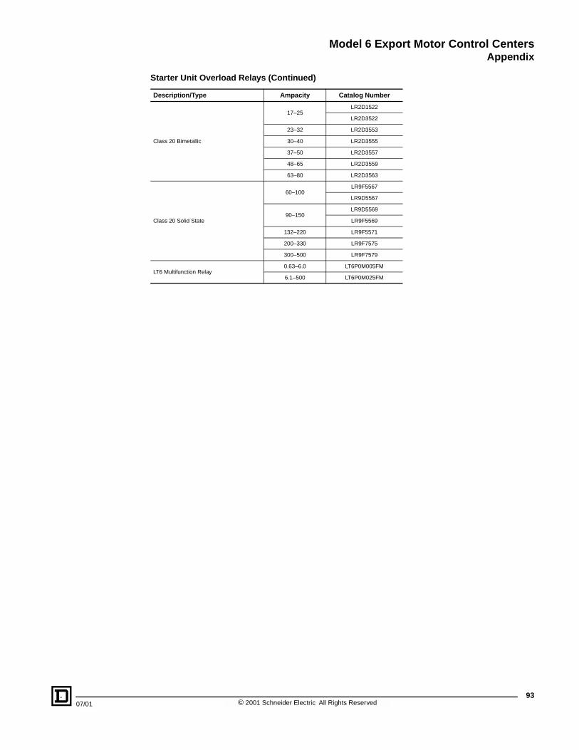
Model 6 Export Motor Control CentersAppendix
07/01
Class 20 Bimetallic
17–25LR2D1522
LR2D3522
23–32 LR2D3553
30–40 LR2D3555
37–50 LR2D3557
48–65 LR2D3559
63–80 LR2D3563
Class 20 Solid State
60–100LR9F5567
LR9D5567
90–150LR9D5569
LR9F5569
132–220 LR9F5571
200–330 LR9F7575
300–500 LR9F7579
LT6 Multifunction Relay0.63–6.0 LT6P0M005FM
6.1–500 LT6P0M025FM
Starter Unit Overload Relays (Continued)
Description/Type Ampacity Catalog Number
93© 2001 Schneider Electric All Rights Reserved

Model 6 Export Motor Control CentersAppendix
94
Items Subject to Customer Agreement
IEC Standard 60439-1 Paragraph Model 6 Export MCC Standard Agreement
4.7 Rated Diversity Factory 1.0
6.1.1.2 Suitability for arctic climateFor outdoor installations of the IP 24 enclosure, the temperature must be maintained above 0 degrees C.
6.1.3 Suitability for operation above 1000 mThe MCC is rated for operation up to and including 1000 m. The customer must request special derating for the MCC above 1000 m.
6.2 Special service conditionsNo special conditions are agreed to, other than conditions listed in the Technical Information table on page 18.
6.2.10 Electrical and radiated interferencesDesigned for EMC environment 1 per paragraph 7.10.1. Other considerations must be requested by the customer.
6.3.1 Conditions during transport storage and erection Same conditions as specified in the Technical Information table on page 18.
7.1.3 Terminals for external conductors
For power conductors of main compartments, see the tables on page 30.
Load power cables meet IEC 60439 requirements
Control connections - see output unit features beginning on page 8.
Neutral conductors connections are sized for 50% capacity
7.2.1.1 Degree of protection required for intended installation
IP 20 (indoor)
Option for indoor IP 52
Option for outdoor IP 24
7.4.2 Choice of protective measures against direct contactTool access is required to enter the external enclosure which is IP 20 minimum degree of protection, provided that installation instructions are followed.
7.4.3 Choice of protective measure against direct contactProtective circuit method via interconnected bus bar, provided that installation instructions are followed.
7.4.6 Accessibility in service by authorized personnelInternal form of separation Form 2b and 4a. Inspections, adjustments, replacements, maintenance, and extension should not be performed while the assembly is energized.
7.5.2.3 Values of prospective short circuit currentOne incoming unit is provided. Refer to short circuit withstand strength of the main device selected, and the outgoing functional units in this catalog.
7.5.4 Coordination of short circuit protection devicesOutgoing units are selectively coordinated for clearing each faulted circuit without affecting the continuity of supply for the other outgoing units.
7.6.4.1 Insertion interlock Provided for preventing insertion or removal while under load
7.6.4.3 Degree of protection after removal of a removable partAfter removal of an outgoing unit, the form of separation is not maintained unless the vertical bus cover is installed manually.
7.7 Form of separation Forms 2b and 4a
7.9.1 Input voltage variations for electronic equipment supply Voltage rating for devices is nominal supply +/- 10%
7.9.4, item b) Supply frequency variation Deviation of normal frequency of up to +/- 1%
8.2.1.6 Ambient air temperature for temperature-rise test Between +10 and +40 degrees Celsius
8.2.3.2.3, item d) Value of neutral bar current for short-circuit test Minimum of 50% of horizontal bus bar rating
8.3.1 Repetition of electrical operation test on siteFull functional test is performed at the factory. Additional site tests must be specified by the user and will be at additional charge.
© 2001 Schneider Electric All Rights Reserved 07/01

Model 6 Export Motor Control CentersIndex
07/01
BBus Bars . . . . . . . . . . . . . . . . . . . . . . . . . . . . . . . . . . . . . . . . . . . . . . . . . . . . . . . . . . . . . 11
CCE Marking . . . . . . . . . . . . . . . . . . . . . . . . . . . . . . . . . . . . . . . . . . . . . . . 15, 18, 24, 50, 86
Certification . . . . . . . . . . . . . . . . . . . . . . . . . . . . . . . . . . . . . . . . . . . . . . . . . . . . . . . . . . . 49ASEFA . . . . . . . . . . . . . . . . . . . . . . . . . . . . . . . . . . . . . . . . . . . . . . . . . . . . . 18, 39, 49
LOVAG . . . . . . . . . . . . . . . . . . . . . . . . . . . . . . . . . . . . . . . . . . . . . . . . . . . . . 18, 39, 49Type Tested Assemblies . . . . . . . . . . . . . . . . . . . . . . . . . . . . . . . . . . . . . . . . . . . . . . 6Type Tested Assemblies (TTA) . . . . . . . . . . . . . . . . . . . . . . . . . . . . . . . . . . . . . . 7, 49
Circuit Breakers . . . . . . . . . . . . . . . . . . . . . . . . . . . . . . . . . . . . . . . . . . . . . . . . . . . . . . . . 13
Branch . . . . . . . . . . . . . . . . . . . . . . . . . . . . . . . . . . . . . . . . . . . . . . . . . . . . . . . . 35–36High Interrupting . . . . . . . . . . . . . . . . . . . . . . . . . . . . . . . . . . . . . . . . . . . . . . . . . . . . 13Main . . . . . . . . . . . . . . . . . . . . . . . . . . . . . . . . . . . . . . . . . . . . . . . . . . . . . . . . . . 26, 28
Main and Branch. . . . . . . . . . . . . . . . . . . . . . . . . . . . . . . . . . . . . . . . . . . . . . . . . 88–89MERLIN GERIN COMPACT NS. . . . . . . . . . . . . . . . . . . . . . . . . 13, 28, 35, 40, 88–90Starter Unit . . . . . . . . . . . . . . . . . . . . . . . . . . . . . . . . . . . . . . . . . . . . . . . . . . 39, 89–90
Thermal Magnetic . . . . . . . . . . . . . . . . . . . . . . . . . . . . . . . . . . . . . . . . . . . 8, 13, 28, 35
Contactor Utilization. . . . . . . . . . . . . . . . . . . . . . . . . . . . . . . . . . . . . . . . . . . . . . . . . . . . . 48
ContactorsStarter Unit . . . . . . . . . . . . . . . . . . . . . . . . . . . . . . . . . . . . . . . . . . . . . . . . . . 41–48, 91
Control Power . . . . . . . . . . . . . . . . . . . . . . . . . . . . . . . . . . . . . . . . . . . . . . . . . . . . . . . . 8–9
Control Station Plate . . . . . . . . . . . . . . . . . . . . . . . . . . . . . . . . . . . . . . . . . . . . . . . . . . . . 10
Control Voltage . . . . . . . . . . . . . . . . . . . . . . . . . . . . . . . . . . . . . . . . . . . . . . . . . . . . . . . . 40
CoordinationCircuit Breaker/Contactor . . . . . . . . . . . . . . . . . . . . . . . . . . . . . . . . . . . . . . . . . . . . . 38
Type 1. . . . . . . . . . . . . . . . . . . . . . . . . . . . . . . . . . . . . . . . . . . . . . . . . . . . . . . . . . 8, 38Type 2. . . . . . . . . . . . . . . . . . . . . . . . . . . . . . . . . . . . . . . . . . . . . . . . . . . . . . . . . . 8, 39
DDimensions . . . . . . . . . . . . . . . . . . . . . . . . . . . . . . . . . . . . . . . . . . . . . . . . . . . . . . . . 51–78
EEnclosure Types . . . . . . . . . . . . . . . . . . . . . . . . . . . . . . . . . . . . . . . . . . . . . . . . . . . . . . . 21
Conduit Entry . . . . . . . . . . . . . . . . . . . . . . . . . . . . . . . . . . . . . . . . . . . . . . . . . . . 54–78
IEC . . . . . . . . . . . . . . . . . . . . . . . . . . . . . . . . . . . . . . . . . . . . . . . . . . . . . . . . . . . . . . 22IP 20 and IP 52 . . . . . . . . . . . . . . . . . . . . . . . . . . . . . . . . . . . . . . . . . . . . . . . . . . . . . 52IP 24 . . . . . . . . . . . . . . . . . . . . . . . . . . . . . . . . . . . . . . . . . . . . . . . . . . . . . . . . . . . . . 53
NEMA . . . . . . . . . . . . . . . . . . . . . . . . . . . . . . . . . . . . . . . . . . . . . . . . . . . . . . . . . . . . 21
95© 2001 Schneider Electric All Rights Reserved

Model 6 Export Motor Control CentersIndex
96
FFeatures
Bus Bar . . . . . . . . . . . . . . . . . . . . . . . . . . . . . . . . . . . . . . . . . . . . . . . . . . . . . . . . . . . 11
Functional (Outgoing) Unit . . . . . . . . . . . . . . . . . . . . . . . . . . . . . . . . . . . . . . . . . . . . . 8Incoming Device . . . . . . . . . . . . . . . . . . . . . . . . . . . . . . . . . . . . . . . . . . . . . . . . . . . . 13Internal Separation . . . . . . . . . . . . . . . . . . . . . . . . . . . . . . . . . . . . . . . . . . . . . . . . . . 14
Structural. . . . . . . . . . . . . . . . . . . . . . . . . . . . . . . . . . . . . . . . . . . . . . . . . . . . . . . . . . . 6
HHandles
Rotary . . . . . . . . . . . . . . . . . . . . . . . . . . . . . . . . . . . . . . . . . . . . . . . . . . . 10, 13, 28, 35Toggle . . . . . . . . . . . . . . . . . . . . . . . . . . . . . . . . . . . . . . . . . . . . . . . . . . . 10, 13, 28, 35
Horizontal Bus Bars . . . . . . . . . . . . . . . . . . . . . . . . . . . . . . . . . . . . . . . . . . . . . . . . . . 11, 82
Horizontal Ground Bus. . . . . . . . . . . . . . . . . . . . . . . . . . . . . . . . . . . . . . . . . . . . . . . . . . . 12
IIEC Degrees of Protection . . . . . . . . . . . . . . . . . . . . . . . . . . . . . . . . . . . . . . . . . . . . . . . .22
Publication 60529 . . . . . . . . . . . . . . . . . . . . . . . . . . . . . . . . . . . . . . . . . . . . . . . . . . . 22
Incoming Devices. . . . . . . . . . . . . . . . . . . . . . . . . . . . . . . . . . . . . . . . . . . . . . . . . . . . . . . 26
MMain Lugs. . . . . . . . . . . . . . . . . . . . . . . . . . . . . . . . . . . . . . . . . . . . . . . . . . . . . . . . . . 13, 26
MERLIN GERINCircuit Breakers . . . . . . . . . . . . . . . . . . . . . . . . . . . . . . . . . . . 4, 13, 28, 35, 40, 88–90
NNeutral Bus . . . . . . . . . . . . . . . . . . . . . . . . . . . . . . . . . . . . . . . . . . . . . . . . . . . . . . . . .12, 31
Neutral Lug Assembly . . . . . . . . . . . . . . . . . . . . . . . . . . . . . . . . . . . . . . . . . . . . . . . . . . . 31
OOptions. . . . . . . . . . . . . . . . . . . . . . . . . . . . . . . . . . . . . . . . . . . . . . . . . . . . . . . . . . . . . . . 15
Bussing . . . . . . . . . . . . . . . . . . . . . . . . . . . . . . . . . . . . . . . . . . . . . . . . . . . . . . . . . . . 25
Four-Wire . . . . . . . . . . . . . . . . . . . . . . . . . . . . . . . . . . . . . . . . . . . . . . . . . . . . . . . . . 31Structure . . . . . . . . . . . . . . . . . . . . . . . . . . . . . . . . . . . . . . . . . . . . . . . . . . . . . . . . . . 24
Overload RelaysStarter Unit . . . . . . . . . . . . . . . . . . . . . . . . . . . . . . . . . . . . . . . . . . . . . . . . . . 40, 92–93
© 2001 Schneider Electric All Rights Reserved 07/01

Model 6 Export Motor Control CentersIndex
07/01
PPOWERLOGIC
Circuit Monitor. . . . . . . . . . . . . . . . . . . . . . . . . . . . . . . . . . . . . . . . . . . . . . . . . . . 13, 32
Power Meter . . . . . . . . . . . . . . . . . . . . . . . . . . . . . . . . . . . . . . . . . . . . . . . . . . . . 13, 33
Programmable Logic Controllers (PLCs) . . . . . . . . . . . . . . . . . . . . . . . . . . . . . . . . . . . . . 15
RRelays
Starter Unit . . . . . . . . . . . . . . . . . . . . . . . . . . . . . . . . . . . . . . . . . . . . . . . . . . . . . . . . 15
SSections
Relay - 15 Inches (381 mm) Deep . . . . . . . . . . . . . . . . . . . . . . . . . . . . . 58–60, 73–74
Relay - 20 Inches (508 mm) Deep . . . . . . . . . . . . . . . . . . . . . . . . . . . . . 65–66, 77–78Autotransformer Starters . . . . . . . . . . . . . . . . . . . . . . . . . . . . . . . . . . . . . . . 67–69Main/Branch Devices. . . . . . . . . . . . . . . . . . . . . . . . . . . . . . . . . . . . . . . . . . 67–69
Standard - 15 Inches (381 mm) Deep . . . . . . . . . . . . . . . . . . . . . . . . . . 54–57, 71–72Standard - 20 Inches (508 mm) Deep . . . . . . . . . . . . . . . . . . . . . . . . . . 61–64, 75–76
SelectionsControl Voltage . . . . . . . . . . . . . . . . . . . . . . . . . . . . . . . . . . . . . . . . . . . . . . . . . . . . . 40
Enclosure . . . . . . . . . . . . . . . . . . . . . . . . . . . . . . . . . . . . . . . . . . . . . . . . . . . . . . . . . 21
Shipping Weights . . . . . . . . . . . . . . . . . . . . . . . . . . . . . . . . . . . . . . . . . . . . . . . . . . . . . . . 78
StandardsANSI . . . . . . . . . . . . . . . . . . . . . . . . . . . . . . . . . . . . . . . . . . . . . . . . . . . . . . . . . . . . . . 6ANSI Z55.1-967 . . . . . . . . . . . . . . . . . . . . . . . . . . . . . . . . . . . . . . . . . . . . . . . . . . . . 81
EN 60439-1. . . . . . . . . . . . . . . . . . . . . . . . . . . . . . . . . . . . . . . . . . . . . . . . . . . . . 18, 49IEC 439. . . . . . . . . . . . . . . . . . . . . . . . . . . . . . . . . . . . . . . . . . . . . . . . . . . . . . . . 29, 36IEC 60439-1 . . . . . . . . . . . . . . . . . . . . . . . . . . . . . . . . . . . . 4, 6, 12, 14, 18, 40, 49, 80
IEC 60529. . . . . . . . . . . . . . . . . . . . . . . . . . . . . . . . . . . . . . . . . . . . . 18, 22, 49, 80–81IEC 60947-1 . . . . . . . . . . . . . . . . . . . . . . . . . . . . . . . . . . . . . . . . . . . . . . . . . . . . 18, 49IEC 60947-2 . . . . . . . . . . . . . . . . . . . . . . . . . . . . . . . . . . . . . . . . . . . . . . . . . 13, 18, 49
IEC 60947-3 . . . . . . . . . . . . . . . . . . . . . . . . . . . . . . . . . . . . . . . . . . . . . . . . . 18, 49, 80IEC 60947-4 . . . . . . . . . . . . . . . . . . . . . . . . . . . . . . . . . . . . . . . . . . . . . . 18, 48–49, 80IEC 60947-4-1 . . . . . . . . . . . . . . . . . . . . . . . . . . . . . . . . . . . . . . . . . . . . . . . . . . . . . . 39
IEC 947-2 . . . . . . . . . . . . . . . . . . . . . . . . . . . . . . . . . . . . . . . . . . . . . . . . . . . . . . . . . 35IEC 947-4-1 . . . . . . . . . . . . . . . . . . . . . . . . . . . . . . . . . . . . . . . . . . . . . . . . . . 8, 38–39NEMA Standards Publication 250 . . . . . . . . . . . . . . . . . . . . . . . . . . . . . . . . . . . . . . 21
UL 50 . . . . . . . . . . . . . . . . . . . . . . . . . . . . . . . . . . . . . . . . . . . . . . . . . . . . . . . . . . . . 21
97© 2001 Schneider Electric All Rights Reserved

Model 6 Export Motor Control CentersIndex
98
TTELEMECANIQUE
Contactors. . . . . . . . . . . . . . . . . . . . . . . . . . . . . . . . . . . . . . . . . . . . . . . . . . . . . 4, 8, 40
Pilot Devices . . . . . . . . . . . . . . . . . . . . . . . . . . . . . . . . . . . . . . . . . . . . . . . . . . . . . 4, 10Relays . . . . . . . . . . . . . . . . . . . . . . . . . . . . . . . . . . . . . . . . . . . . . . . . . . . . . . . . . . 4, 40
Terminal Blocks . . . . . . . . . . . . . . . . . . . . . . . . . . . . . . . . . . . . . . . . . . . . . . . . . . . . . 14, 84
Three-Phase, Four-Wire Systems . . . . . . . . . . . . . . . . . . . . . . . . . . . . . . . . . . . . . . . 26, 31
Type Tested Assemblies . . . . . . . . . . . . . . . . . . . . . . . . . . . . . . . . . . . . . . . . . . . . . 6–7, 49
UUnit
Branch Feeder . . . . . . . . . . . . . . . . . . . . . . . . . . . . . . . . . . . . . . . . . . . . . . . . . . . 9, 35
COMPAC 6 . . . . . . . . . . . . . . . . . . . . . . . . . . . . . . . . . . . . . . . . . 10, 15, 41–45, 84–85Functional . . . . . . . . . . . . . . . . . . . . . . . . . . . . . . . . . . . . . . . . . . . . . . . . . . . . . . . 8, 14Motor Starter . . . . . . . . . . . . . . . . . . . . . . . . . . . . . . . . . . . . . . . . . . . . . . . . . . . . . 9, 38
Utilization Categories . . . . . . . . . . . . . . . . . . . . . . . . . . . . . . . . . . . . . . . . . . . . . . . . . 40, 48
VVertical Bus . . . . . . . . . . . . . . . . . . . . . . . . . . . . . . . . . . . . . . . . . . . . . . . . . . . . . . . . 11, 82
WWireways . . . . . . . . . . . . . . . . . . . . . . . . . . . . . . . . . . . . . . . . . . . . . . . . . . . . . . . . . . 14, 81
© 2001 Schneider Electric All Rights Reserved 07/01


Square D Company1990 Sandifer Blvd.Seneca, SC 296781-888-SquareD(1-888-778-2733)www.SquareD.com
Schneider Canada Inc.19 Waterman Avenue, M4B 1 Y2Toronto, Ontario
Catalog No. 8998CT0101 July 2001 © 2001 Schneider Electric All Rights Reserved 1-800-565-6699www.schneider-electric.ca