Embed Size (px)
Citation preview
© EMC TEST SYSTEMS, L.P. – SEPTEMBER 2002 REV E– PN 399058
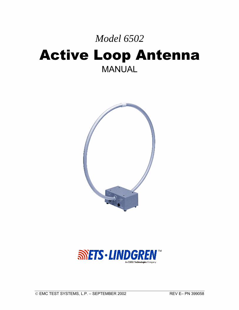
Model 6502
Active Loop Antenna MANUAL
MODEL 6502 ACTIVE LOOP ANTENNA
© EMC TEST SYSTEMS, L.P. – SEPTEMBER 2002 REV E – PN 399058
EMC Test Systems, L.P. reserves the right to make changes to any products herein to improve functioning, design, or for any other reason. Nothing contained herein shall constitute EMC Test Systems, L.P. assuming any liability whatsoever arising out of the application or use of any product or circuit described herein. EMC Test Systems, L.P. does not convey any license under its patent rights or the rights of others.
© Copyright 2002 by EMC Test Systems, L.P. All Rights Reserved. No part of this document may be copied by any means
without written permission from EMC Test Systems, L.P.
E-MAIL & INTERNET [email protected] http://www.ets-lindgren.com
USA 1301 Arrow Point Dr., Cedar Park, TX 78613 P.O. Box 80589, Austin, TX 78708-0589 Tel 512.531.6400 Fax 512.531.6500
FINLAND Euroshield OY Mekaanikontie 1 27510, Eura, Finland Tel 358.2.838.3300 Fax 358.2.865.1233
SINGAPORE Lindgren RF Enclosures Asia-Pacific 87 Beach Road #06-02 Chye Sing Building Singapore 189695 Tel 65.536.7078 Fax 65.536.7093
MODEL 6502 ACTIVE LOOP ANTENNA
© EMC TEST SYSTEMS, L.P. – SEPTEMBER 2002 REV E – PN 399058
Table of Contents
INTRODUCTION.................................................................................................................................. 1
STANDARD CONFIGURATION ......................................................................................................... 2
OPTIONS ............................................................................................................................................... 2
MOUNTING........................................................................................................................................... 3
OPERATION ......................................................................................................................................... 3
SATURATION INDICATOR ....................................................................................................................... 3 POWER INDICATOR ................................................................................................................................ 3 USE OF CALIBRATION DATA .................................................................................................................. 3
TYPICAL DATA.................................................................................................................................... 4
CALIBRATION..................................................................................................................................... 5
BATTERY CHARGER.......................................................................................................................... 5
SPECIFICATIONS ................................................................................................................................ 8
ELECTRICAL ......................................................................................................................................... 8 PHYSICAL ............................................................................................................................................. 8
MAINTENANCE ................................................................................................................................... 9
WARRANTY........................................................................................................................................ 10
EUROPEAN COMMUNITY DECLARATION OF CONFORMITY................................................ 11
MODEL 6502 ACTIVE LOOP ANTENNA
© EMC TEST SYSTEMS, L.P. – SEPTEMBER 2002 REV E – PN 399058
MODEL 6502 ACTIVE LOOP ANTENNA Introduction
© EMC TEST SYSTEMS, L.P. – SEPTEMBER 2002 1 REV E – PN 399058
INTRODUCTION The ETS-Lindgren Model 6502 is an Active Receiving Loop Antenna with a frequency range of 10 kHz to 30 MHz. This antenna is specifically designed to perform commercial emissions standards testing. The Model 6502 can be used for any magnetic testing, particularly MIL-STD 461B. A radio frequency preamplifier is built into the base of this loop antenna and provides a 50 ohm output which is used by a receiver. The preamplifier helps the loop antenna produce good sensitivity and almost constant antenna factors. Power for the preamplifier is supplied by rechargeable sealed batteries. Front panel controls and indicators for the preamplifier include a power switch, power-on indicator and a receptacle for the batter charger. The battery charger which is switch selectable for 115 VAC/230 VAC operation is included. The charger operates at 50 Hz/60 Hz.
Standard Configuration MODEL 6502 ACTIVE LOOP ANTENNA
2 © EMC TEST SYSTEMS, L.P. – SEPTEMBER 2002 REV E – PN 399058
STANDARD CONFIGURATION
• Antenna assembly • Mounting bracket designed to accept an ETS-Lindgren or
other tripod mount with standard ¼ in x 20 threads • Battery Charger • Individually calibrated per IEEE STD 291. Actual individual
calibration factors and signed Certificate of Calibration Conformance are included.
OPTIONS Remote Monitor: An optional remote monitor is available that allows you to view the power and saturation indicators from up to 10m (32.8 ft) away. Tripods: ETS-Lindgren offers two nonmetallic, non-reflective tripods for use at both indoor and outdoor EMC test sites. The Model 4-TR, constructed of linen phenolic and delrin, is designed with an adjustable center post for precise height adjustments. Maximum height for the 4-TR is 2.0 m (80.0 in), while minimum height is 94 cm (37.0 in). This tripod can support up to an 11.8 kg (26.0 lb) load. The 7-TR tripod has several different configurations, including options for manual or pneumatic polarization. This tripod provides increased stability for physically large antennas. Its unique design allows for quick assembly/disassembly and convenient storage. Quick height adjustment and locking wheels provide ease of use during testing. This tripod can support a 13.5 kg (30 lb) load. For the 7-TR series, maximum height is 2.17 m (85.8 in), with a minimum height of .8 m (31.8 in). The 7-TR is constructed of PVC and fiberglass components.
MODEL 6502 ACTIVE LOOP ANTENNA Mounting
© EMC TEST SYSTEMS, L.P. – SEPTEMBER 2002 3 REV E – PN 399058
MOUNTING The Model 6502 is fitted with a mounting bracket threaded to accept a tripod mount with standard 1/4 “ x 20 threads. To mount the loop antenna, thread a ¼” x 20 mounting knob or fixture into the base of the mounting bracket. Take care not to cross thread this connection as permanent damage to the antenna mount could occur.
OPERATION
SATURATION INDICATOR This LED illuminates when input signal intensity exceeds the 1 dB compression level of 5 volts per meter and stays on for about 1 second afterward.
POWER INDICATOR This LED illuminates to show that the loop is “on” and functional. When the charge on the battery has decreased to the point the antenna calibration is no longer valid, the LED extinguishes. Note: The antenna is still functioning and will provide reasonable output signals until the batteries are exhausted.
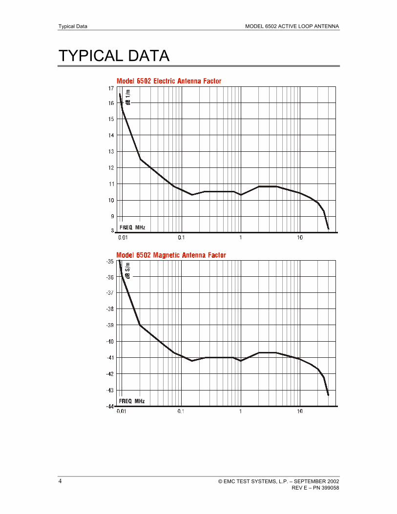
USE OF CALIBRATION DATA In order to calculate the field strength you must add the signal level + cable loss + antenna factor. The sum equals the relative field strength. Cable loss should be measured periodically for each cable used in testing.
Typical Data MODEL 6502 ACTIVE LOOP ANTENNA
4 © EMC TEST SYSTEMS, L.P. – SEPTEMBER 2002 REV E – PN 399058
TYPICAL DATA
MODEL 6502 ACTIVE LOOP ANTENNA Calibration
© EMC TEST SYSTEMS, L.P. – SEPTEMBER 2002 5 REV E – PN 399058
CALIBRATION The IEEE 291-1991 Induction-Field Method of Calibration is used on the Model 6502. By using relatively close spacing between the transmitter and the receiver at frequencies below 30 MHz, the use of free space magnetic induction field from a transmitting loop antenna is most suitable. This method yields almost no reflection from the ground or nearby objects. The value of magnetic field produced can be expressed in terms of the equivalent free-space electric component that would exist in a free space radiation field because loop antennas are used both for transmitting and receiving.
BATTERY CHARGER The Model 6502 is powered by two (2) – six (6) VDC sealed lead-acid batteries. A battery charger is supplied with the unit. The battery charging port on the front of the unit allows for easy recharging of the unit. Two (2) internal fuses protect the unit from unintentional shorting. The EMCO brand Voltage-Selectable Battery Charger is solely intended for charging the sealed lead-acid batteries found in EMCO products. The battery charger is a means of providing the necessary charge voltage and current from either a 115 or 230 VAC 50/60 Hz source. NOTE: It is necessary to select the proper input voltage PRIOR to connecting the battery charger to the power mains. The voltage selection switch is located adjacent to the power input receptacle. To maintain safety requirements, use the CSA certified power cord provided. If it is necessary to provide other means of attaching the battery charger to the power mains it is required that a type HD 21 (PVC cord) or type HD22 (rubber cord) with a nominal cross section of 0.75 mm 2 be used. The battery charger provides both fast and trickle charge operation. Switching from one charge mode to the other is provided
Battery Charger MODEL 6502 ACTIVE LOOP ANTENNA
6 © EMC TEST SYSTEMS, L.P. – SEPTEMBER 2002 REV E – PN 399058
automatically by the charger. The front panel indicator marched “Fast Charge” lights when the battery charger is in the fast charge mode. When the “Power On” light is illuminated and the “Fast Charge” light is extinguished, the batter charger is in the trickle charge mode. The antenna should be connected to the battery charger in “Trickle Charge” mode when not in use. Charging time is approximately eight hours when batteries are completely discharged. Note: The antenna is not designed to operate using that Battery Charger as a power source. Batteries should provide power to the amplifier for approximately 16 hours before recharging is required. The battery charger is protected against overcurrent by a 200 mA 250 VAC time-delay fuse. If it becomes necessary to replace the fuse, use a fuse of the same type and rating to maintain safe operations. The fuse is accessible by removing the two (2) “Phillips” head screws on the underside of the unit. Always remove main power before opening the house. The output of the battery charger is protected against overcurrent conditions by use of “fold-back” circuitry. SPECIFICATIONS Input voltage: 115/230 VAC selectable Input frequency: 50/60 Hz Input power: 20 VA max Protection class: Class II double insulated Input fuse rating: 200 mA time-delay type 5x20 mm Input power connection : IEC-320 power inlet Output voltage: 12 VDC (13.5-15 VDC) Output current: 350 mA Safety approvals: TUV, CSA
IMPORTANT The battery charger allows for the selection of either 115 or 230 VAC single phase, 50 or 60 Hz. This selection should be made prior to applying power to the battery charger.
MODEL 6502 ACTIVE LOOP ANTENNA Battery Charger
© EMC TEST SYSTEMS, L.P. – SEPTEMBER 2002 7 REV E – PN 399058
There are two LED’s on the body of the separate battery charger. The “Power On” LED illuminates when the charger is plugged into an AC outlet. (115/230 VAC user selectable). The “Fast Charge” LED illuminates when the battery is charging and turns off when the battery is fully charged. Once the battery charger has completed the “Fast Charge” cycle, the charger will automatically switch to “Trickle Charge” mode. The antenna should be connected to the battery charger in “Trickle Charge” model when not in use. Charging time is approximately eight hours when batteries are completely discharged. Note: The antenna is not designed to operate using the Battery Charger as a power source. Batteries should provide power to amplifier for approximately 16 hours before recharging is required.
Specifications MODEL 6502 ACTIVE LOOP ANTENNA
8 © EMC TEST SYSTEMS, L.P. – SEPTEMBER 2002 REV E – PN 399058
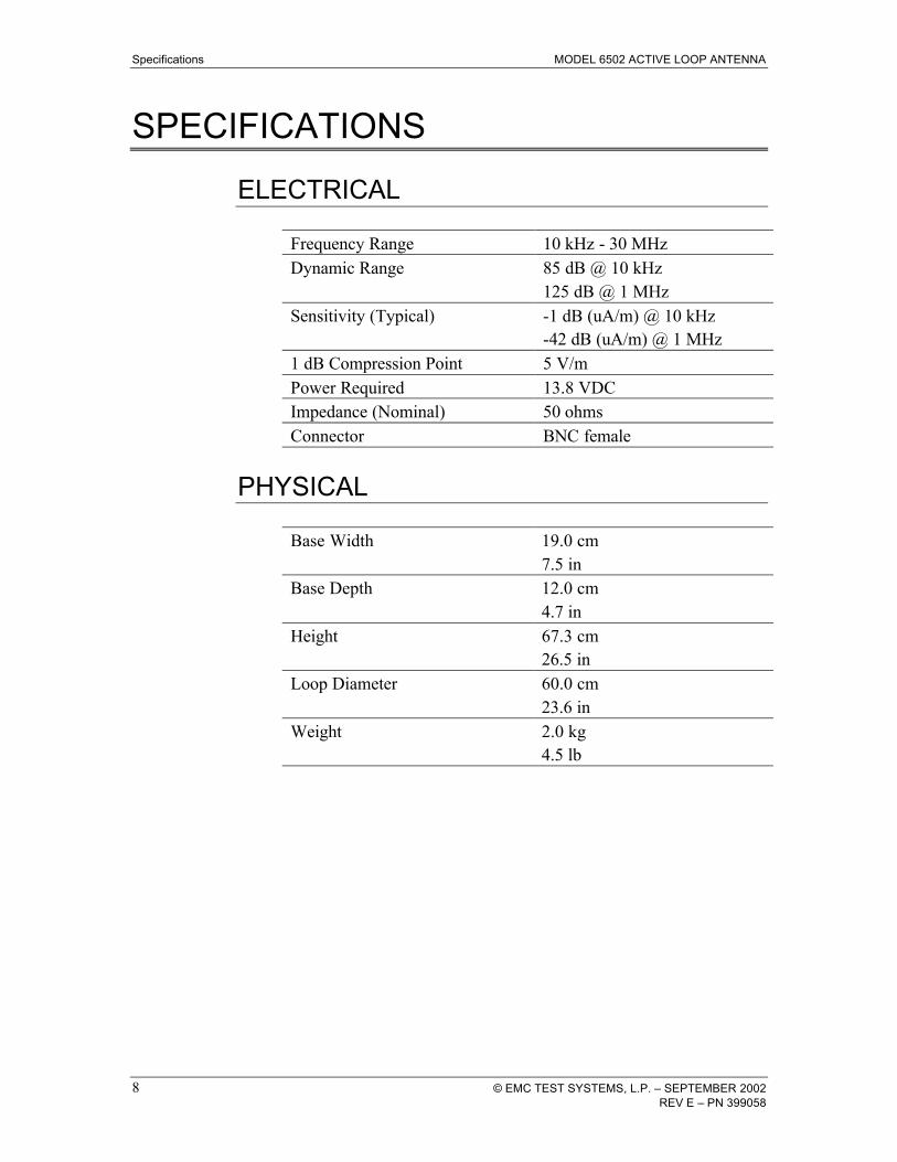
SPECIFICATIONS
ELECTRICAL Frequency Range 10 kHz - 30 MHz Dynamic Range 85 dB @ 10 kHz
125 dB @ 1 MHz Sensitivity (Typical) -1 dB (uA/m) @ 10 kHz
-42 dB (uA/m) @ 1 MHz 1 dB Compression Point 5 V/m Power Required 13.8 VDC Impedance (Nominal) 50 ohms Connector BNC female
PHYSICAL Base Width 19.0 cm
7.5 in Base Depth 12.0 cm
4.7 in Height 67.3 cm
26.5 in Loop Diameter 60.0 cm
23.6 in Weight 2.0 kg
4.5 lb
MODEL 6502 ACTIVE LOOP ANTENNA Maintenance
© EMC TEST SYSTEMS, L.P. – SEPTEMBER 2002 9 REV E – PN 399058
MAINTENANCE To ensure reliable and repeatable long-term performance, annual recalibration of your antennas by ETS-Lindgren’s experienced technicians is recommended. Our staff can recalibrate almost any type or brand of antenna. Please call to receive a service order number prior to sending an antenna to us for calibration. For more information about our calibration services or to place an order for antenna calibration visit our calibration website at http://www.antennacalibration.com/.
Warranty MODEL 6502 ACTIVE LOOP ANTENNA
10 © EMC TEST SYSTEMS, L.P. – SEPTEMBER 2002 REV E – PN 399058
WARRANTY
EMC Test Systems, L.P., hereinafter referred to as the Seller, warrants that standard EMCO products are free from defect in materials and workmanship for a period of two (2) years from date of shipment. Standard EMCO Products include the following: v Antennas, Loops, Horns v GTEM cells, TEM cells, Helmholtz Coils v LISNs, PLISNs, Rejection cavities & Networks v Towers, Turntables, Tripods & Controllers v Field Probes, Current Probes, Injection Probes
If the Buyer notifies the Seller of a defect within the warranty period, the Seller will, at the Seller’s option, either repair and/or replace those products that prove to be defective.
There will be no charge for warranty services performed at the location the Seller designates. The Buyer must, however, prepay inbound shipping costs and any duties or taxes. The Seller will pay outbound shipping cost for a carrier of the Seller’s choice, exclusive of any duties or taxes. If the Seller determines that warranty service can only be performed at the Buyer’s location, the Buyer will not be charged for the Seller’s travel related costs.
This warranty does not apply to:
v Normal wear and tear of materials v Consumable items such as fuses, batteries, etc. v Products that have been improperly installed, maintained or used v Products which have been operated outside the specifications v Products which have been modified without authorization v Calibration of products, unless necessitated by defects
THIS WARRANTY IS EXCLUSIVE. NO OTHER WARRANTY, WRITTEN OR ORAL, IS EXPRESSED OR IMPLIED, INCLUDING BUT NOT LMITED TO, THE IMPLIED WARRANTIES OF MERCHANTABILITY AND FITNESS FOR A PARTICULAR PURPOSE. THE REMEDIES PROVIDED BY THIS WARRANTY ARE THE BUYER’S SOLE AND EXCLUSIVE REMEDIES. IN NO EVENT IS THE SELLER LIABLE FOR ANY DAMAGES WHATSOEVER, INCLUDING BUT NOT LIMITED TO, DIRECT, INDIRECT, SPECIAL, INCIDENTAL, OR CONSEQUENTIAL DAMAGES, WHETHER BASED ON CONTRACT, TORT, OR ANY OTHER LEGAL THEORY.
Note: Please contact the Seller’s sales department for a Return Materials Authorization (RMA) number before shipping equipment to us.
MODEL 6502 ACTIVE LOOP ANTENNA European Community Declaration of Conformity
© EMC TEST SYSTEMS, L.P. – SEPTEMBER 2002 11 REV E – PN 399058
EUROPEAN COMMUNITY DECLARATION OF CONFORMITY
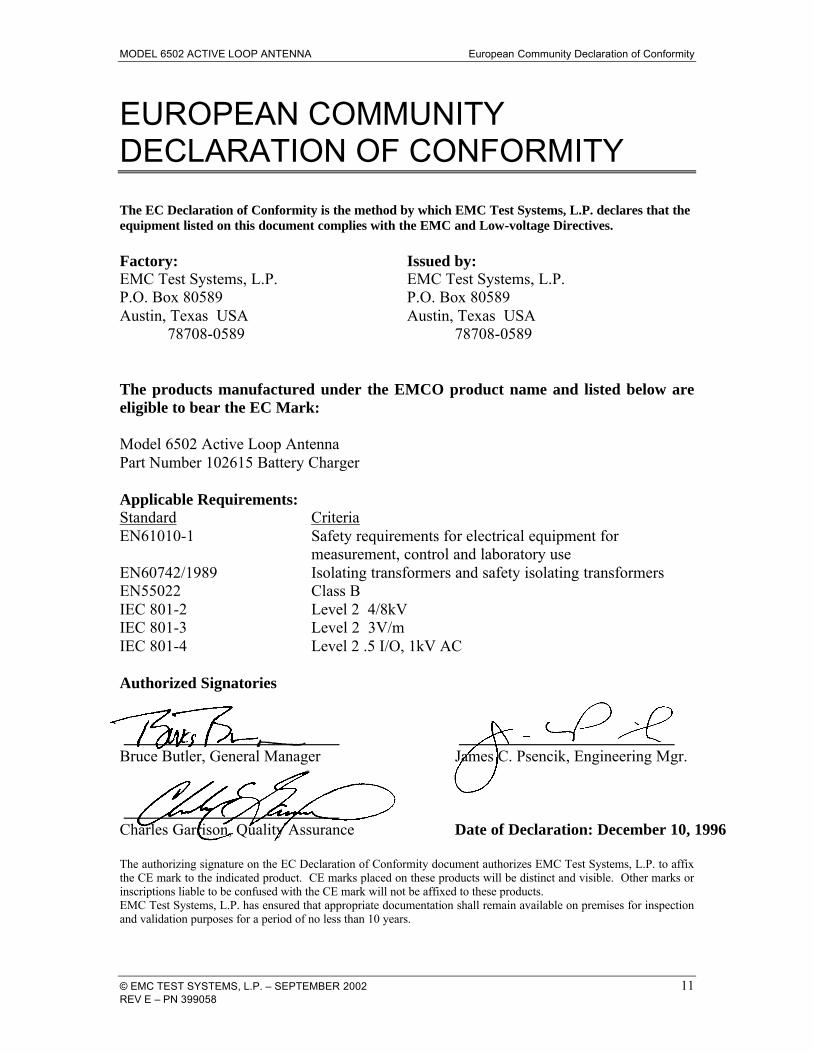
The EC Declaration of Conformity is the method by which EMC Test Systems, L.P. declares that the equipment listed on this document complies with the EMC and Low-voltage Directives. Factory: Issued by: EMC Test Systems, L.P. EMC Test Systems, L.P. P.O. Box 80589 P.O. Box 80589 Austin, Texas USA Austin, Texas USA 78708-0589 78708-0589 The products manufactured under the EMCO product name and listed below are eligible to bear the EC Mark: Model 6502 Active Loop Antenna Part Number 102615 Battery Charger Applicable Requirements: Standard Criteria EN61010-1 Safety requirements for electrical equipment for measurement, control and laboratory use EN60742/1989 Isolating transformers and safety isolating transformers EN55022 Class B IEC 801-2 Level 2 4/8kV IEC 801-3 Level 2 3V/m IEC 801-4 Level 2 .5 I/O, 1kV AC Authorized Signatories ___________________________ ___________________________ Bruce Butler, General Manager James C. Psencik, Engineering Mgr. ___________________________ Charles Garrison, Quality Assurance Date of Declaration: December 10, 1996 The authorizing signature on the EC Declaration of Conformity document authorizes EMC Test Systems, L.P. to affix the CE mark to the indicated product. CE marks placed on these products will be distinct and visible. Other marks or inscriptions liable to be confused with the CE mark will not be affixed to these products. EMC Test Systems, L.P. has ensured that appropriate documentation shall remain available on premises for inspection and validation purposes for a period of no less than 10 years.