Embed Size (px)
Citation preview
MODEL 814M
DIRECT THERMAL PRINTER
OPERATOR’S MANUAL
PART NUMBER 880047-0100
Revised 03/25 JSR © Copyright 2014 by Microcom Corporation, Lewis Center, Ohio – All rights reserved. Printed in the United States of America

ii

iii
Proprietary Statement This manual contains information proprietary to Microcom Corporation. This information is intended solely for the use of parties operating and maintaining such equipment described herein. The reproduction, disclosure and/or use of such information without the authority of Microcom Corporation to other parties is strongly prohibited. Product Enhancements Microcom Corporation is committed to the continual improvement of performance and quality in our products. For this reason, specifications are subject to change without notice. Liability Disclaimer Microcom Corporation makes every effort to assure that all information and specifications contained in this manual are accurate; however, mistakes are sometimes made. Microcom Corporation shall not be liable for any damages resulting from the use or misuse of this product. The exclusion or limitation involving consequential or incidental damage does not apply to all states, therefore, the limitation mentioned above may or may not apply. HyperTerminal® and HyperAccess® are trademarks of Hilgraeve Inc. Centronics® is a registered trademark of Data Computer Corporation. HP® and LaserJet II® are trademarks of Hewlett-Packard Company. Arial® is a registered trademark of The Monotype Corporation. TrueType® is a registered trademark of Apple Computer, Inc. Microsoft®, Windows®, Windows NT® are registered trademarks of Microsoft Corporation. Instapak® is a registered trademark of Sealed Air Corporation. Other products and company names mentioned herein may be trademarks of their respective owners.
iv
Safety Instructions Before installing and using the printer, please read the following items carefully:
• Install the printer on a flat and stable place.
• Reserve adequate space around the printer so that the operation and maintenance can be performed conveniently.
• Do not use or store the printer in direct sunlight, strong heat, high humidity or dew
condensation.
• Do not place the printer in a place exposed to vibration or impact.
• Connect the DC adapter to an appropriately grounded outlet. Avoid sharing one electrical outlet with large power motors and other devices that may cause the fluctuation of voltage.
• Take care not to spill liquids into the printer. In case this happens, turn off the power
immediately.
• Do not allow the printer to start printing when there is no paper installed, otherwise the print head and platen roller may be damaged.
• Use only recommended paper.
• Shut down the printer when connecting or disconnecting the interface connectors to
avoid damage to control board.
• Use the lowest print darkness setting possible to produce acceptable print quality to prolong printhead life.
• Disassembly of the printer should only be done by properly trained technicians.
• Keep this manual available for reference.
1
Table of Contents 1 General Description.................................................................Page 3
1.1 Introduction......................................................................................................3 1.2 Main Features .................................................................................................3
2 Specifications...........................................................................Page 4
2.1 Technical Specifications ..................................................................................4 2.2 Paper Specifications........................................................................................5
3 Structure and Functions .........................................................Page 7
3.1 Appearance .....................................................................................................7 3.2 External Dimensions .......................................................................................8 3.3 Printer Mechanism ........................................................................................11
3.3.1 Printer Mechanism (without paper holder)...............................................11 3.3.2 Printer Mechanism Explanation...............................................................11
3.4 Presenter.......................................................................................................13 3.4.1 Appearance .............................................................................................13 3.4.2 Presenter Parts Explanation....................................................................14
3.5 Paper Holder .................................................................................................14 3.5.1 Paper Holder Appearance .......................................................................14 3.5.2 Paper Holder Module Explanation...........................................................14
3.6 Interface ........................................................................................................15 4 Installation..............................................................................Page 16
4.1 Unpacking .....................................................................................................16 4.2 Assembling the Printer ..................................................................................16 4.3 Connecting the Grounding Wire ....................................................................16 4.4 Connecting the AC Power Adapter................................................................17 4.5 Connecting the Interface Cable .....................................................................17 4.6 Loading Paper Roll ........................................................................................18
4.6.1 Loading Process......................................................................................18 4.6.2 Semi-automatic Paper Loading or Manual Paper Loading ......................20
4.7 Installing the Printer.......................................................................................21 4.8 Installing Printer Driver ..................................................................................28
5 Routine Maintenance.............................................................Page 29
5.1 Cleaning Print head.......................................................................................29 5.2 Cleaning sensors...........................................................................................29
5.2.1 Cleaning paper end sensor .....................................................................29 5.2.2 Cleaning paper loading sensor................................................................30 5.2.3 Cleaning paper out sensor ......................................................................30 5.2.4 Paper Retract Sensor ..............................................................................31
5.3 Cleaning Printing Platen ................................................................................32 5.4 Resetting Cutter Manually .............................................................................32 5.5 Manual Removal of the Jammed Paper ........................................................33
2
6 Interface Signal......................................................................Page 33 6.1 RS-232 Interface........................................................................................... 33
6.1.1 Parameter ............................................................................................... 33 6.1.2 RS-232 Serial Interface Signals.............................................................. 34
6.2 IEEE 1284 Parallel Interface (optional)......................................................... 34 6.2.1 Parameters ............................................................................................. 34 6.2.2 Parallel Interface Printer Status (/FAULT pin and PE pin) ...................... 34 6.2.3 Parallel Interface Signals ........................................................................ 35 6.2.4 Time Sequence of Data Receiving ......................................................... 36
6.3 USB Interface (optional) ............................................................................... 36 6.3.1 Power Interface....................................................................................... 37
7 Troubleshooting and Maintenance ......................................Page 37
7.1 Common Errors and Settlement ................................................................... 37 7.1.1 Problems during Paper Loading ............................................................. 37 7.1.2 Problems during Printing ........................................................................ 38 7.1.3 Problems during Paper Out .................................................................... 38 7.1.4 Other Problems....................................................................................... 39
Appendix Self-test Page........................................................Page 40
3
1 General Description
1.1 Introduction The 814M is a high performance thermal printer with a cutter and optional presenter. The printer can accept up to 203mm (outer diameter) paper rolls. The maximum print width is 216mm. It is designed to be used in kiosk applications such that require Letter or A4 paper widths. The 814M printer consists of the following modules:
− Thermal printing unit, − Cutter, − Paper holder (optional), − Presenter (optional),
Depending upon the paper roll installation mode, the 814M printer can be structured for either horizontal or vertical modes. The 814M printer can be connected with host devices by serial, parallel, USB, or ethernet interfaces. Drivers are available for WINDOWS XP/Vista/7/8 and LINUX.
1.2 Main Features • Printing
− High-speed printing − Thermal print with low noise − High reliability
• Presenter
− Accommodate and present printout − Retract printout after programmable wait time − Hold printout for user to take
• Applications
− Character processing: 1-6 times enlargement vertically and horizontally, Rotation (0, 90, 180, 270°), white/black reverse, underline, inverse
− Barcode printing in both vertical and horizontal direction − Character font size (font A or font B) can be selected via a command
• Printer maintenance
− Easy paper roll loading − Easy printhead cleaning − Various features and parameters can be selected via software − Auto paper cutting − Semi-automatic paper loading − Mark identification and checkout
4
2 Specifications
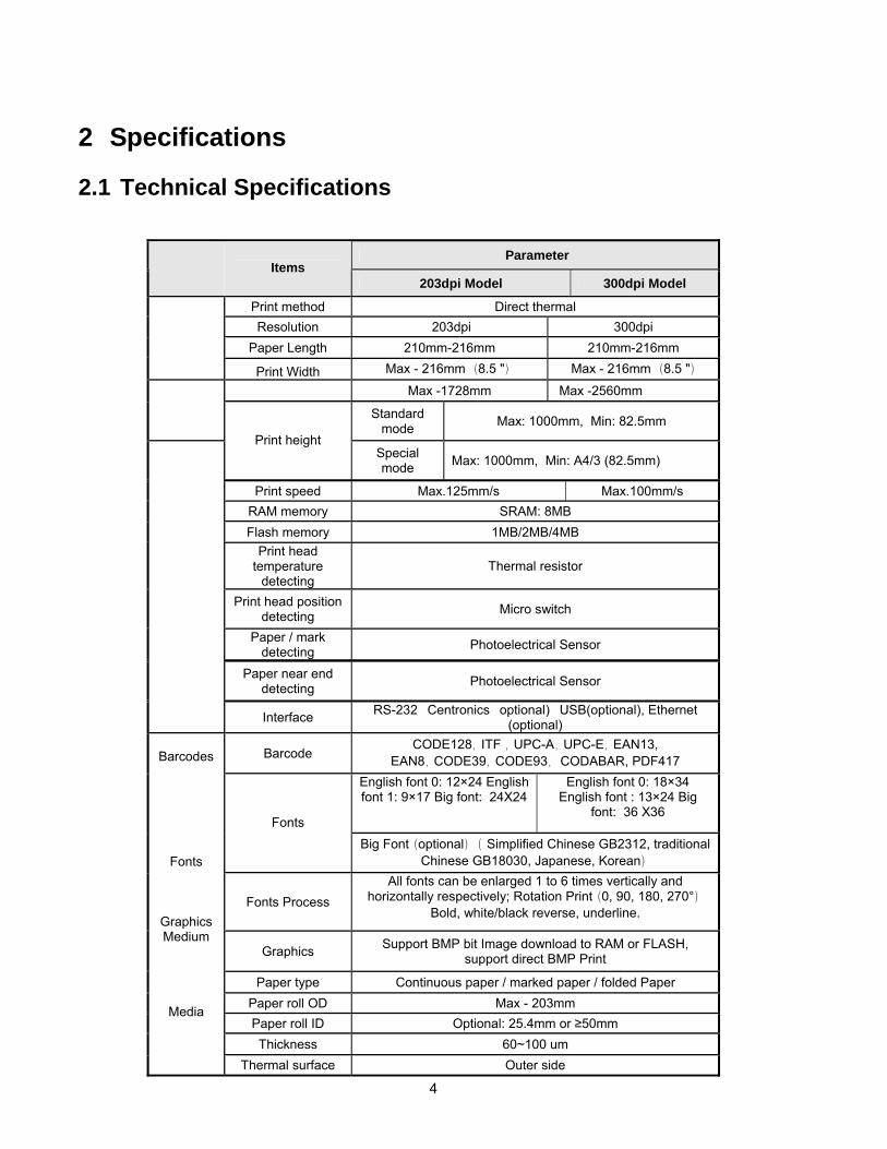
2.1 Technical Specifications
Parameter Items
203dpi Model 300dpi Model
Print method Direct thermal Resolution 203dpi 300dpi
Paper Length 210mm-216mm 210mm-216mm
Print Width Max - 216mm (8.5 ") Max - 216mm (8.5 ")
Max -1728mm Max -2560mm Standard
mode Max: 1000mm, Min: 82.5mm Print height
Special mode Max: 1000mm, Min: A4/3 (82.5mm)
Print speed Max.125mm/s Max.100mm/s RAM memory SRAM: 8MB Flash memory 1MB/2MB/4MB
Print head temperature
detecting Thermal resistor
Print head position detecting Micro switch
Paper / mark detecting Photoelectrical Sensor
Paper near end detecting Photoelectrical Sensor
Interface RS-232�Centronics�optional)�USB(optional), Ethernet (optional)
Barcode CODE128,ITF ,UPC-A,UPC-E,EAN13,
EAN8,CODE39,CODE93, CODABAR, PDF417 English font 0: 12×24 English font 1: 9×17 Big font: 24X24
English font 0: 18×34 English font : 13×24 Big
font: 36 X36 Fonts
Big Font(optional)( Simplified Chinese GB2312, traditional Chinese GB18030, Japanese, Korean)
Fonts Process All fonts can be enlarged 1 to 6 times vertically and
horizontally respectively; Rotation Print(0, 90, 180, 270°) Bold, white/black reverse, underline.
Graphics Support BMP bit Image download to RAM or FLASH, support direct BMP Print
Paper type Continuous paper / marked paper / folded Paper Paper roll OD Max - 203mm Paper roll ID Optional: 25.4mm or ≥50mm Thickness 60~100 um
Barcodes
Fonts
Graphics Medium
Media
Thermal surface Outer side
5
Note: − DPI: Dots for each inch in printing (one inch equals 25.4 mm) − Character spacing can be adjusted − Actual print speed is influenced by: data speed, print darkness, print duty ratio, commands
used and supply voltage
2.2 Paper Specifications • Paper Type: Continuous paper / marked paper • Paper Supply Method: Paper roll / folded paper • Paper Width: 210mm – 216mm • Paper Thickness: 60um – 100um • Thermal Layer: Outer side of roll • Paper Roll Specification: 50mm (inner dimension of standard core)
25.4mm or ≥ 50mm (inner dimension of optional core) 203mm (maximum paper outer dimension)
• Microcom Corporation Recommended Paper:
Parameter Items
203dpi Model 300dpi Model
Input voltage AC 120V±5%, 50/60Hz Power
Output voltage DC 24V, 2.5A Paper out speed ≥400mm/s Paper retracting
speed ≥400mm/s Presenter
Function modes Retraction/Hold/Commands control/close Print head lifetime ≥100Km
Cutter lifetime ≥500,000 (paper thickness: 0.08mm) Reliability
MTBF 360,000 hours Operation
Environment 5°C to 45°C, 20% to 90% RH (40°C) Environment
Storage Environment -40°C to 60°C, 20% to 93% RH (40°C)
Dimensions 212(L) ×294(W)×97(H) Physics Character Weight About 3.8Kg (without paper roll and paper holder)
Table 2-1 Technical Specifications
Part Number Description 709009-00018 81/2”x5”x451’ – 21#, 1” ID, Outerwound 709009-00019 81/2”x6”x595’ – 21#, 2” ID, Outerwound 709009-00020 81/2”x8”x1134’ – 21#, 2” ID, Outerwound
Table 2-2 Recommended Paper
6
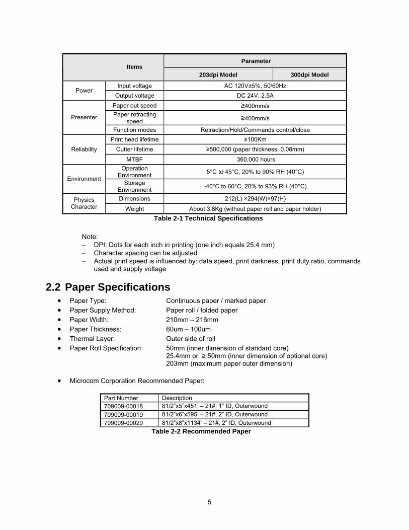
• Marked paper specification In marked paper mode, the printer determines cut position by referencing black mark position. Marked paper should meet the following requirement besides that of standard paper:
− Mark length L1: 20mm ≤ L1 − Mark height L2: 4mm ≤ L2 ≤ 8 mm − Space between adjacent Marks L3: 82.5mm ≤ L3 ≤ 305mm − Mark position on paper: Right, middle or left side on non-thermal sensitive surface of
paper. − Reflectivity: The reflectivity of black mark shall be less than 15% while the paper itself
reflectivity shall exceeds 85%. There should not be any preprint on paper, such as logos, advertisements, etc. on the area between black marks.
Note: − Mark height can be set by adjusting printer configuration, − The paper path has three positions selectable for black mark sensor installation. Only one
sensor is mounted on the right side of the paper path (default) when the printer is delivered. − Black marks are not detected when printer is idle. Paper out is not detected if paper is
removed while printer is idle.
• Folded paper specification
− When using folded paper, be sure to keep the folded line outside of the printing area to avoid paper jams,
− It is recommended to set the cutting position 0.5-2.0mm below the folding line to prevent paper jams,
− Refer to the continuous and marked paper specification to decide the position between the folding line and black mark.
Notes! − Please use the recommended paper or its equivalents. Using other paper may affect print quality
and reduce printhead life. − Do not paste the paper to the shaft core. − Thermal paper may discolor due to exposure to certain chemical, high temperature, or direct sun
light.
Figure 2-1 Mark Position Sketch Map
Figure 2-2 Paper Folding
7
3 Structure and Functions
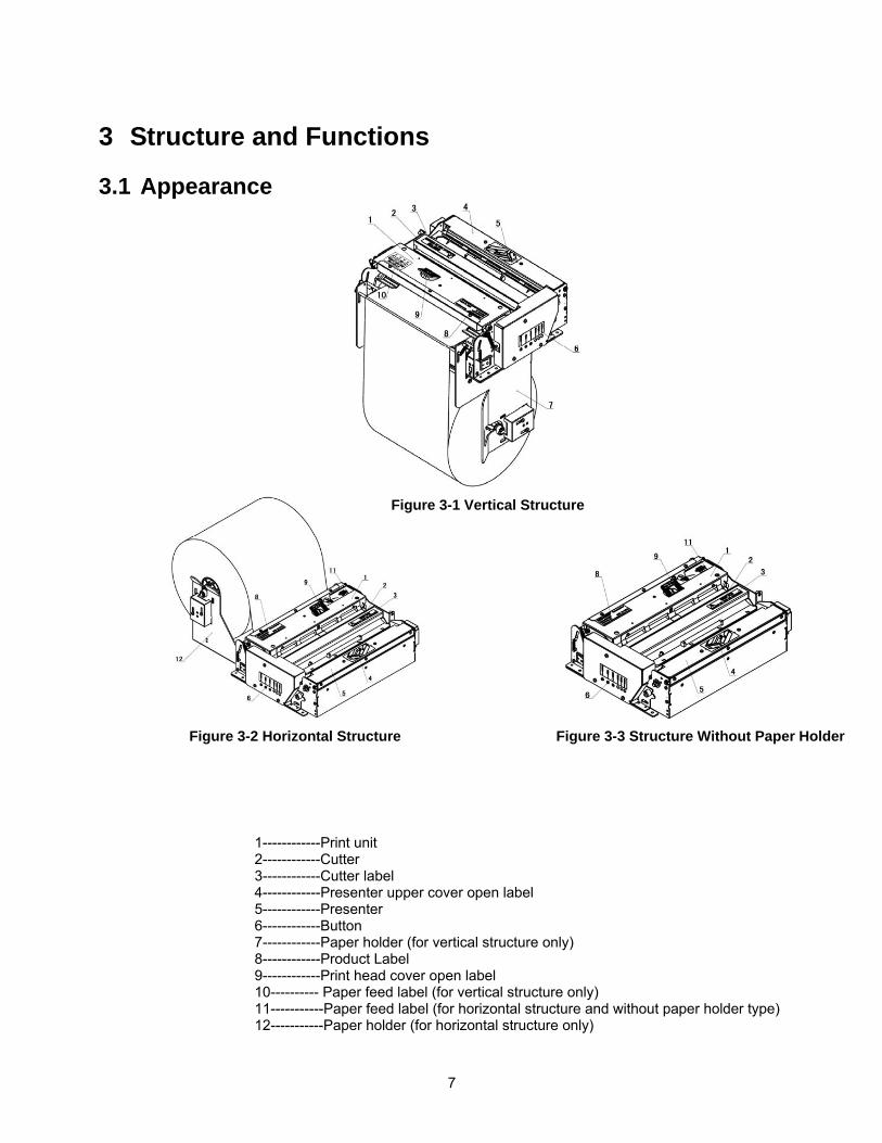
3.1 Appearance
1------------Print unit 2------------Cutter 3------------Cutter label 4------------Presenter upper cover open label 5------------Presenter 6------------Button 7------------Paper holder (for vertical structure only) 8------------Product Label 9------------Print head cover open label 10---------- Paper feed label (for vertical structure only) 11-----------Paper feed label (for horizontal structure and without paper holder type) 12-----------Paper holder (for horizontal structure only)
Figure 3-2 Horizontal Structure Figure 3-3 Structure Without Paper Holder
Figure 3-1 Vertical Structure
8
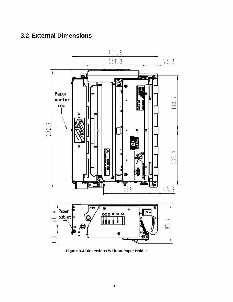
3.2 External Dimensions
Figure 3-4 Dimensions Without Paper Holder
9
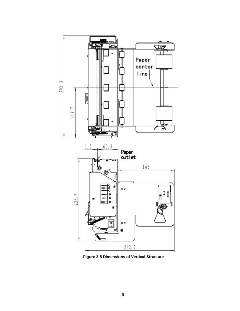
Figure 3-5 Dimensions of Vertical Structure
10
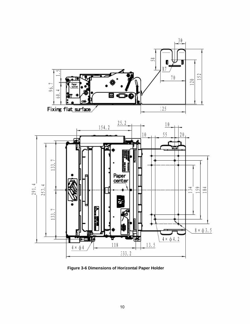
Figure 3-6 Dimensions of Horizontal Paper Holder
11
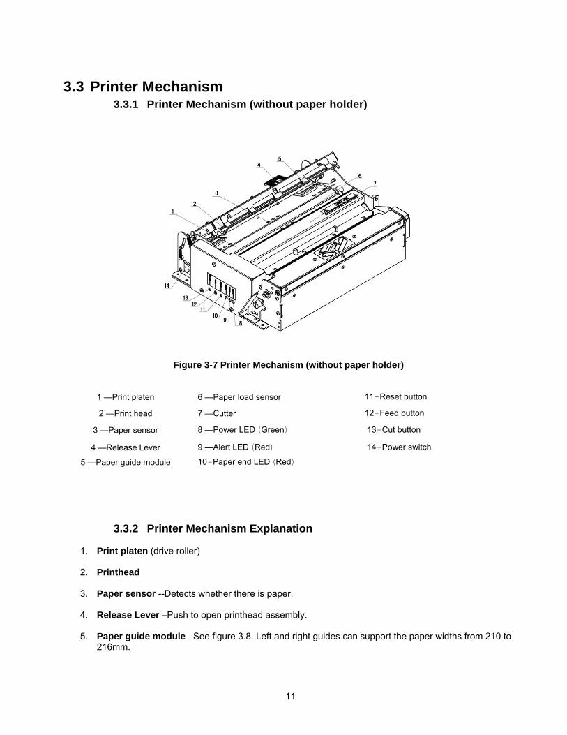
3.3 Printer Mechanism 3.3.1 Printer Mechanism (without paper holder)
3.3.2 Printer Mechanism Explanation
1. Print platen (drive roller)
2. Printhead
3. Paper sensor --Detects whether there is paper.
4. Release Lever –Push to open printhead assembly.
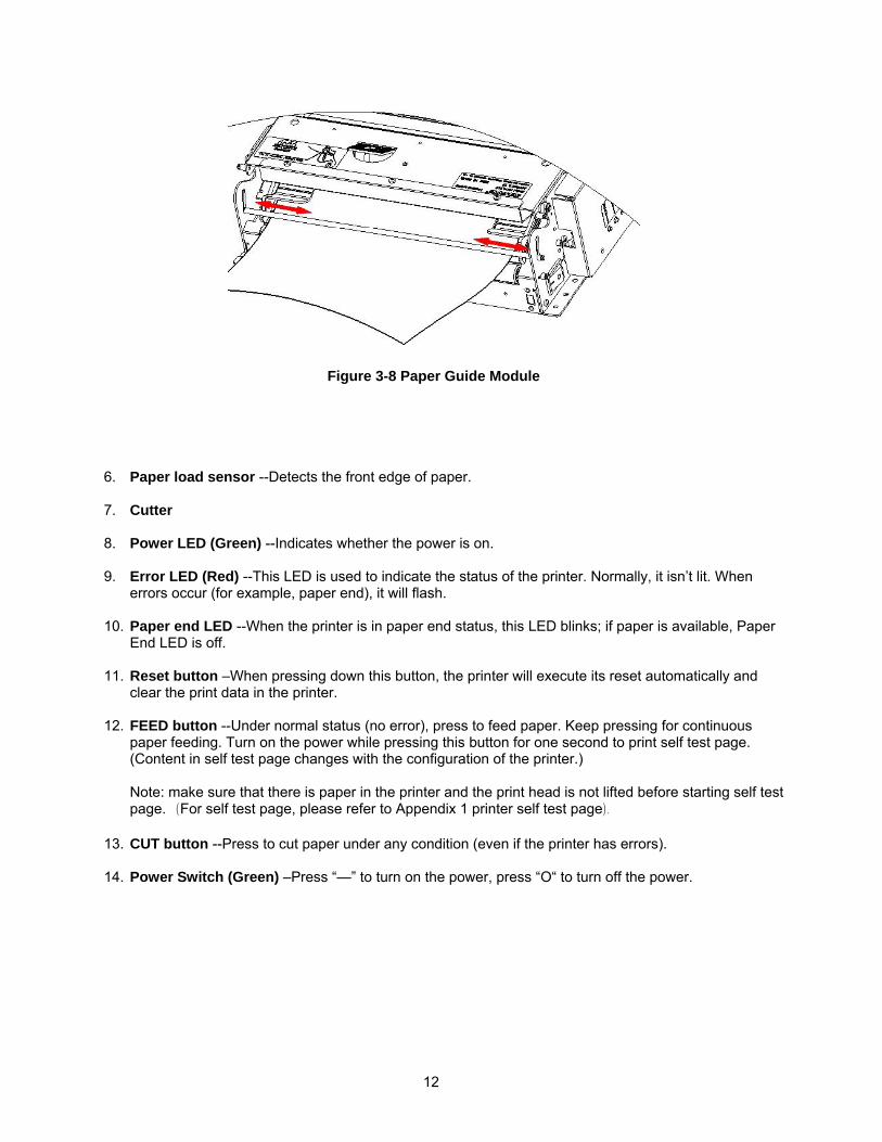
5. Paper guide module –See figure 3.8. Left and right guides can support the paper widths from 210 to 216mm.
1 —Print platen 6 —Paper load sensor 11-Reset button
2 —Print head 7 —Cutter 12-Feed button
3 —Paper sensor 8 —Power LED(Green) 13-Cut button
4 —Release Lever 9 —Alert LED(Red) 14-Power switch
5 —Paper guide module 10-Paper end LED(Red)
Figure 3-7 Printer Mechanism (without paper holder)
12
6. Paper load sensor --Detects the front edge of paper.
7. Cutter
8. Power LED (Green) --Indicates whether the power is on.
9. Error LED (Red) --This LED is used to indicate the status of the printer. Normally, it isn’t lit. When errors occur (for example, paper end), it will flash.
10. Paper end LED --When the printer is in paper end status, this LED blinks; if paper is available, Paper
End LED is off.
11. Reset button –When pressing down this button, the printer will execute its reset automatically and clear the print data in the printer.
12. FEED button --Under normal status (no error), press to feed paper. Keep pressing for continuous
paper feeding. Turn on the power while pressing this button for one second to print self test page. (Content in self test page changes with the configuration of the printer.) Note: make sure that there is paper in the printer and the print head is not lifted before starting self test page. (For self test page, please refer to Appendix 1 printer self test page).
13. CUT button --Press to cut paper under any condition (even if the printer has errors).
14. Power Switch (Green) –Press “—” to turn on the power, press “O“ to turn off the power.
Figure 3-8 Paper Guide Module
13
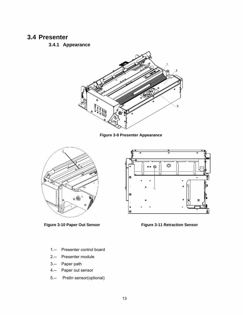
3.4 Presenter 3.4.1 Appearance
1.-- Presenter control board
2.-- Presenter module 3.-- Paper path 4.-- Paper out sensor 5.-- PrstIn sensor(optional)
Figure 3-9 Presenter Appearance
Figure 3-11 Retraction Sensor Figure 3-10 Paper Out Sensor
14
3.4.2 Presenter Parts Explanation
1. Paper loading sensor –Used to detect paper status. 2. Prsln Sensor (optional) –Used to detect whether paper is retracted.
Caution: Paper sensor may be ineffective if exposed to direct sunlight!
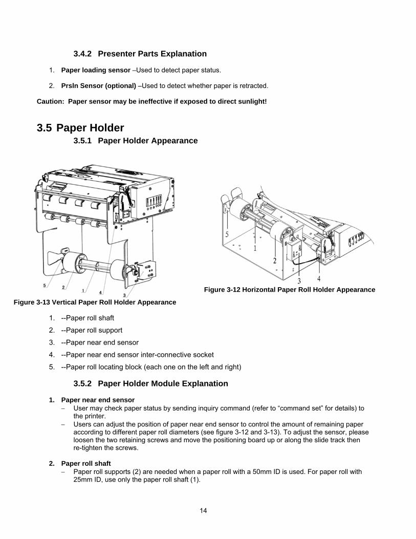
3.5 Paper Holder 3.5.1 Paper Holder Appearance
1. --Paper roll shaft
2. --Paper roll support
3. --Paper near end sensor
4. --Paper near end sensor inter-connective socket
5. --Paper roll locating block (each one on the left and right)
3.5.2 Paper Holder Module Explanation
1. Paper near end sensor − User may check paper status by sending inquiry command (refer to “command set” for details) to
the printer. − Users can adjust the position of paper near end sensor to control the amount of remaining paper
according to different paper roll diameters (see figure 3-12 and 3-13). To adjust the sensor, please loosen the two retaining screws and move the positioning board up or along the slide track then re-tighten the screws.
2. Paper roll shaft
− Paper roll supports (2) are needed when a paper roll with a 50mm ID is used. For paper roll with 25mm ID, use only the paper roll shaft (1).
Figure 3-13 Vertical Paper Roll Holder Appearance
Figure 3-12 Horizontal Paper Roll Holder Appearance
15
3. Paper Roll-Spacer Block − Install paper roll-spacer block on paper holder only when using a 210mm wide paper roll. For
216mm wide paper, remove the paper roll-spacer block. Caution: When you install or remove paper roll-locating block, you should adjust both left and right paper guide modules!
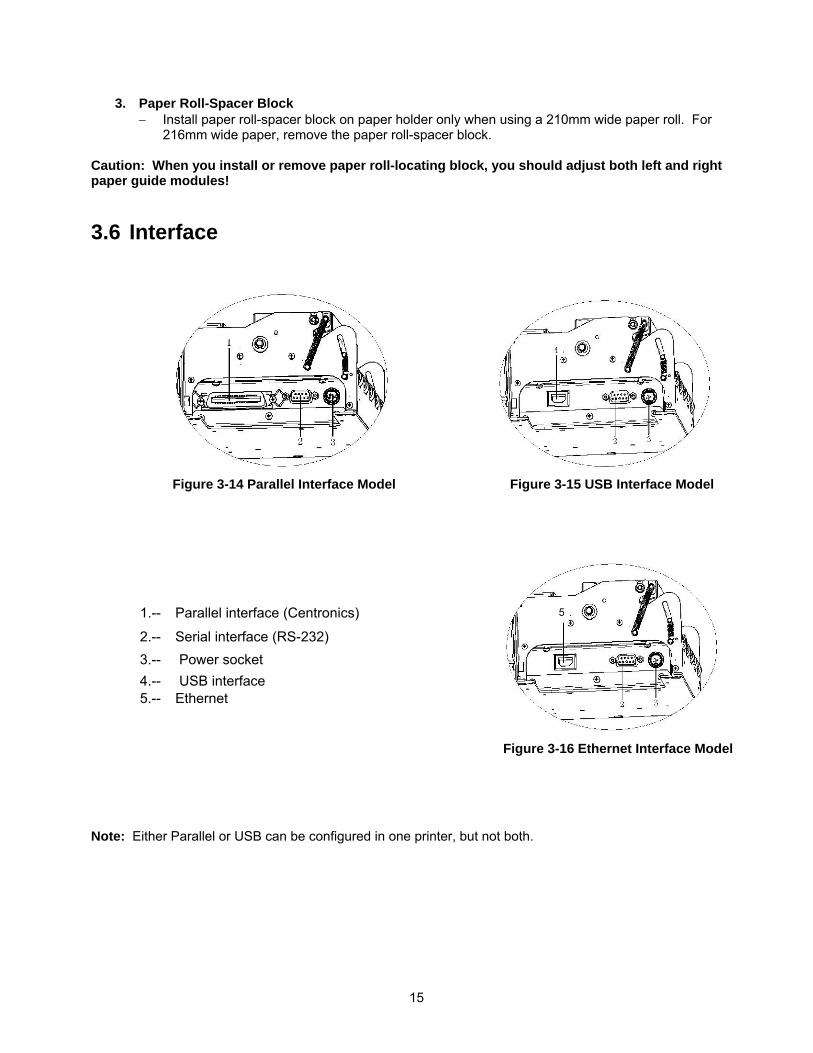
3.6 Interface
1.-- Parallel interface (Centronics)
2.-- Serial interface (RS-232) 3.-- Power socket 4.-- USB interface 5.-- Ethernet
Note: Either Parallel or USB can be configured in one printer, but not both.
Figure 3-15 USB Interface Model Figure 3-14 Parallel Interface Model
Figure 3-16 Ethernet Interface Model
5
16
4 Installation
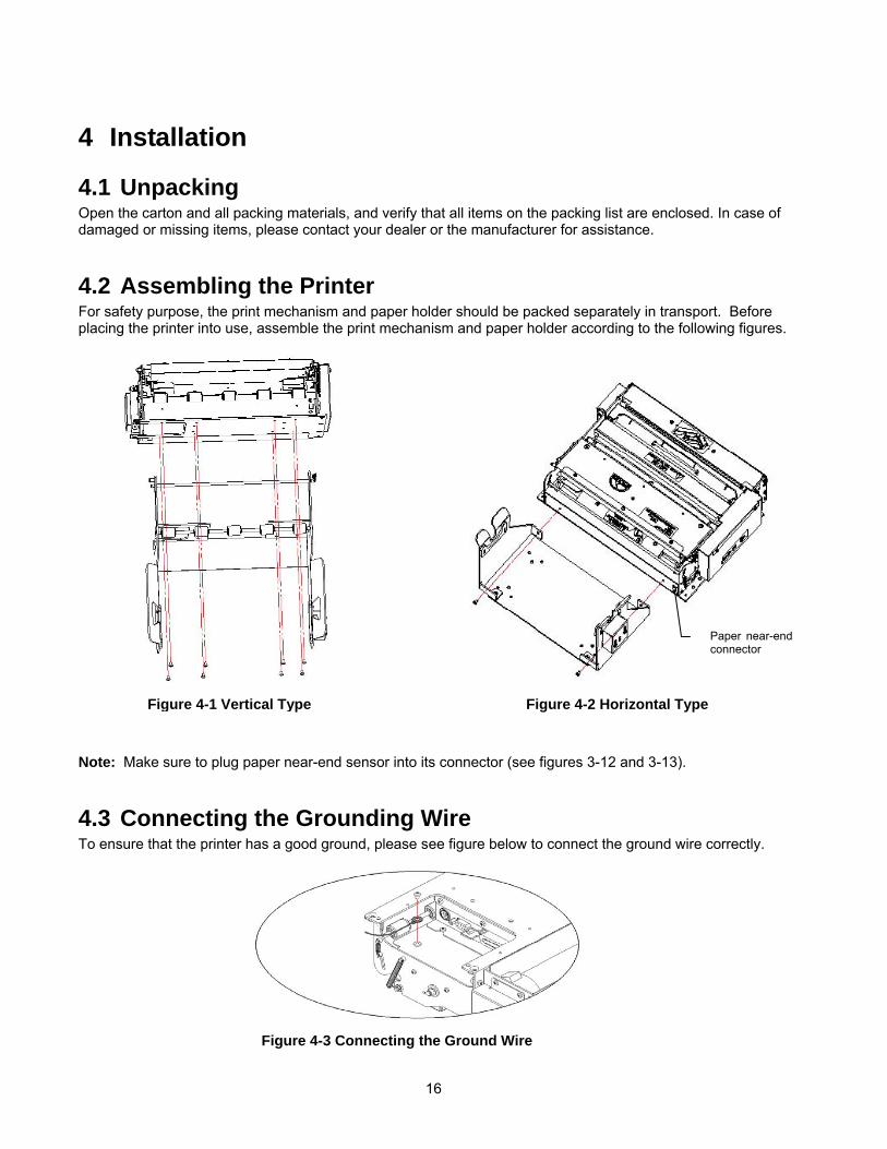
4.1 Unpacking Open the carton and all packing materials, and verify that all items on the packing list are enclosed. In case of damaged or missing items, please contact your dealer or the manufacturer for assistance.
4.2 Assembling the Printer For safety purpose, the print mechanism and paper holder should be packed separately in transport. Before placing the printer into use, assemble the print mechanism and paper holder according to the following figures. Note: Make sure to plug paper near-end sensor into its connector (see figures 3-12 and 3-13).
4.3 Connecting the Grounding Wire To ensure that the printer has a good ground, please see figure below to connect the ground wire correctly.
Figure 4-1 Vertical Type
Figure 4-3 Connecting the Ground Wire
Figure 4-2 Horizontal Type
Paper near-end connector
17
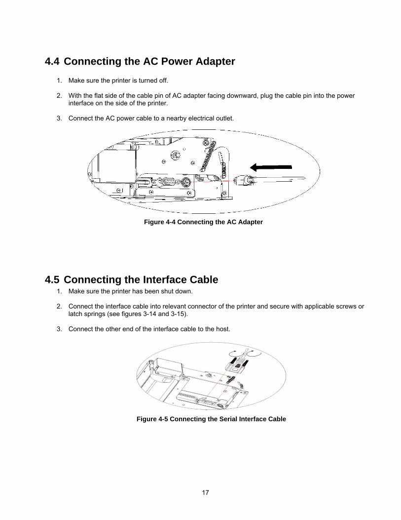
4.4 Connecting the AC Power Adapter
1. Make sure the printer is turned off. 2. With the flat side of the cable pin of AC adapter facing downward, plug the cable pin into the power
interface on the side of the printer.
3. Connect the AC power cable to a nearby electrical outlet.
4.5 Connecting the Interface Cable 1. Make sure the printer has been shut down. 2. Connect the interface cable into relevant connector of the printer and secure with applicable screws or
latch springs (see figures 3-14 and 3-15).
3. Connect the other end of the interface cable to the host.
Figure 4-4 Connecting the AC Adapter
Figure 4-5 Connecting the Serial Interface Cable
18
Notes:
− When connecting the serial interface cable, do not forget to tighten the retaining screws. For parallel interface cable, make sure to close the clips.
− When connecting or disconnecting the interface cable, make sure to hold the plug shell instead of the the cable only.
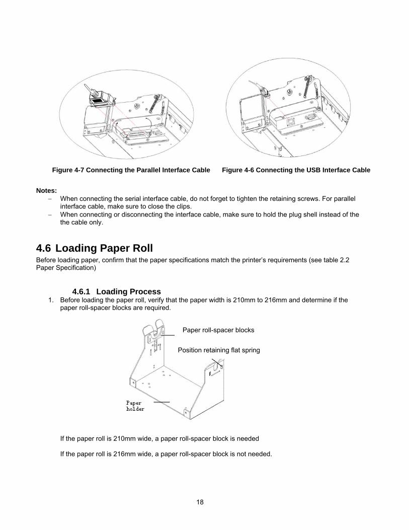
4.6 Loading Paper Roll Before loading paper, confirm that the paper specifications match the printer’s requirements (see table 2.2 Paper Specification)
4.6.1 Loading Process 1. Before loading the paper roll, verify that the paper width is 210mm to 216mm and determine if the
paper roll-spacer blocks are required.
If the paper roll is 210mm wide, a paper roll-spacer block is needed If the paper roll is 216mm wide, a paper roll-spacer block is not needed.
Figure 4-6 Connecting the USB Interface CableFigure 4-7 Connecting the Parallel Interface Cable
Paper roll-spacer blocks
Position retaining flat spring
19
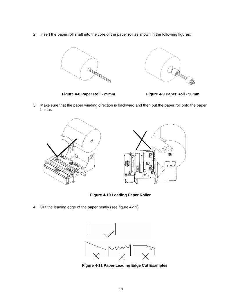
2. Insert the paper roll shaft into the core of the paper roll as shown in the following figures:
3. Make sure that the paper winding direction is backward and then put the paper roll onto the paper holder.
4. Cut the leading edge of the paper neatly (see figure 4-11).
Figure 4-9 Paper Roll - 50mm Figure 4-8 Paper Roll - 25mm
Figure 4-10 Loading Paper Roller
Figure 4-11 Paper Leading Edge Cut Examples
20
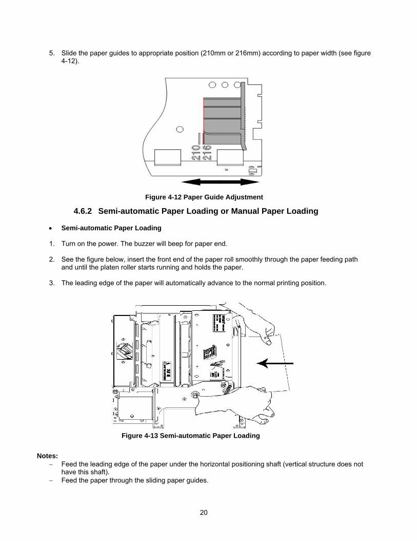
5. Slide the paper guides to appropriate position (210mm or 216mm) according to paper width (see figure 4-12).
4.6.2 Semi-automatic Paper Loading or Manual Paper Loading
• Semi-automatic Paper Loading
1. Turn on the power. The buzzer will beep for paper end. 2. See the figure below, insert the front end of the paper roll smoothly through the paper feeding path
and until the platen roller starts running and holds the paper.
3. The leading edge of the paper will automatically advance to the normal printing position. Notes:
− Feed the leading edge of the paper under the horizontal positioning shaft (vertical structure does not have this shaft).
− Feed the paper through the sliding paper guides.
Figure 4-12 Paper Guide Adjustment
Figure 4-13 Semi-automatic Paper Loading
21
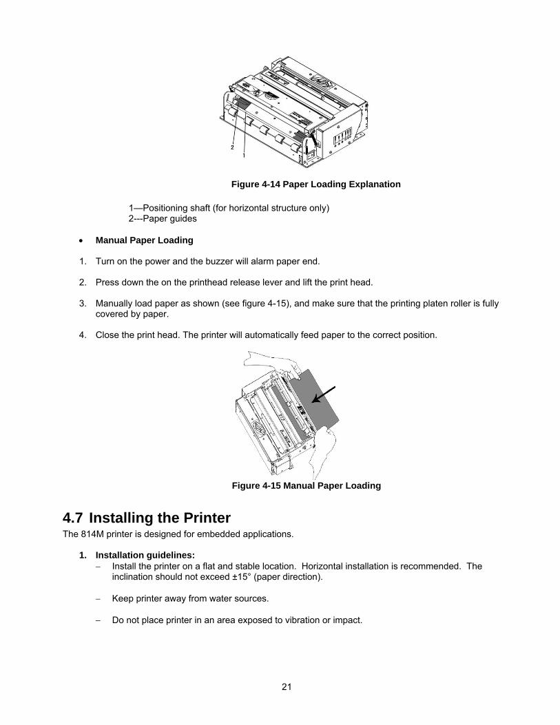
1—Positioning shaft (for horizontal structure only) 2---Paper guides
• Manual Paper Loading
1. Turn on the power and the buzzer will alarm paper end. 2. Press down the on the printhead release lever and lift the print head. 3. Manually load paper as shown (see figure 4-15), and make sure that the printing platen roller is fully
covered by paper. 4. Close the print head. The printer will automatically feed paper to the correct position.
4.7 Installing the Printer The 814M printer is designed for embedded applications.
1. Installation guidelines: − Install the printer on a flat and stable location. Horizontal installation is recommended. The
inclination should not exceed ±15° (paper direction).
− Keep printer away from water sources.
− Do not place printer in an area exposed to vibration or impact.
Figure 4-14 Paper Loading Explanation
Figure 4-15 Manual Paper Loading
22
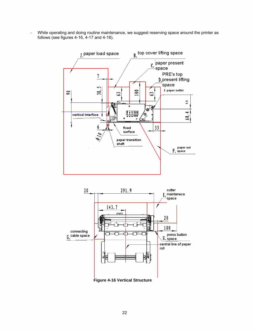
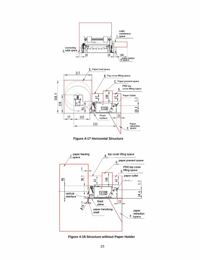
− While operating and doing routine maintenance, we suggest reserving space around the printer as follows (see figures 4-16, 4-17 and 4-18).
Figure 4-16 Vertical Structure
23
Figure 4-17 Horizontal Structure
Figure 4-18 Structure without Paper Holder
24
Notes: − Spaces in above figure include: printer working space, printer routine maintenance and printer
operating space. Specifically, printer work space includes paper accommodation and paper backing space. Printer routine maintenance space includes PRE upper cover opening and cutter access. Printer operating space includes paper loading and cable connection space.
− The dimensions given in above figures are for reference only.
− There should not be any sharp edges or corners around the space to avoid injury.
2. Spaces Explanation
− Paper loading space. Make sure to reserve enough space for semi-automatic paper loading.
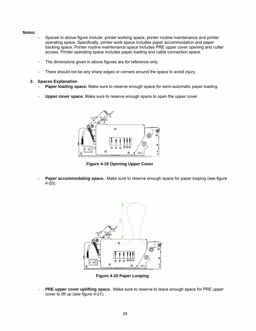
− Upper cover space. Make sure to reserve enough space to open the upper cover.
− Paper accommodating space. Make sure to reserve enough space for paper looping (see figure 4-20).
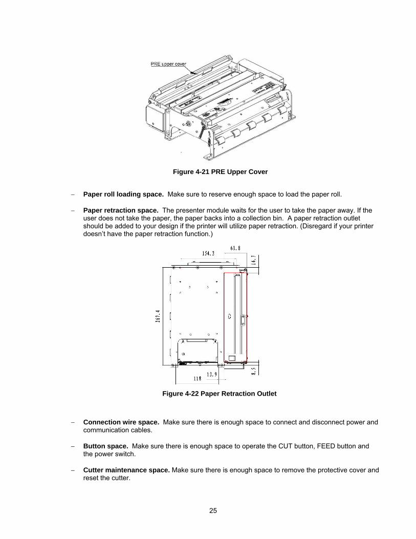
− PRE upper cover uplifting space. Make sure to reserve to leave enough space for PRE upper cover to lift up (see figure 4-21).
Figure 4-19 Opening Upper Cover
Figure 4-20 Paper Looping
25
− Paper roll loading space. Make sure to reserve enough space to load the paper roll.
− Paper retraction space. The presenter module waits for the user to take the paper away. If the user does not take the paper, the paper backs into a collection bin. A paper retraction outlet should be added to your design if the printer will utilize paper retraction. (Disregard if your printer doesn’t have the paper retraction function.)
− Connection wire space. Make sure there is enough space to connect and disconnect power and communication cables.
− Button space. Make sure there is enough space to operate the CUT button, FEED button and
the power switch.
− Cutter maintenance space. Make sure there is enough space to remove the protective cover and reset the cutter.
Figure 4-21 PRE Upper Cover
Figure 4-22 Paper Retraction Outlet
26
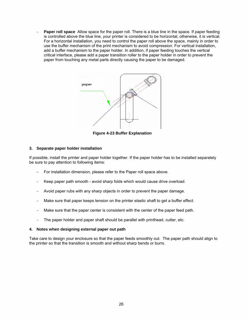
− Paper roll space Allow space for the paper roll. There is a blue line in the space. If paper feeding is controlled above the blue line, your printer is considered to be horizontal, otherwise, it is vertical. For a horizontal installation, you need to control the paper roll above the space, mainly in order to use the buffer mechanism of the print mechanism to avoid compression. For vertical installation, add a buffer mechanism to the paper holder. In addition, if paper feeding touches the vertical critical interface, please add a paper transition roller to the paper holder in order to prevent the paper from touching any metal parts directly causing the paper to be damaged.
3. Separate paper holder installation
If possible, install the printer and paper holder together. If the paper holder has to be installed separately be sure to pay attention to following items:
− For installation dimension, please refer to the Paper roll space above.
− Keep paper path smooth - avoid sharp folds which would cause drive overload.
− Avoid paper rubs with any sharp objects in order to prevent the paper damage.
− Make sure that paper keeps tension on the printer elastic shaft to get a buffer effect.
− Make sure that the paper center is consistent with the center of the paper feed path. − The paper holder and paper shaft should be parallel with printhead, cutter, etc.
4. Notes when designing external paper out path
Take care to design your enclosure so that the paper feeds smoothly out. The paper path should align to the printer so that the transition is smooth and without sharp bends or burrs.
Figure 4-23 Buffer Explanation
27
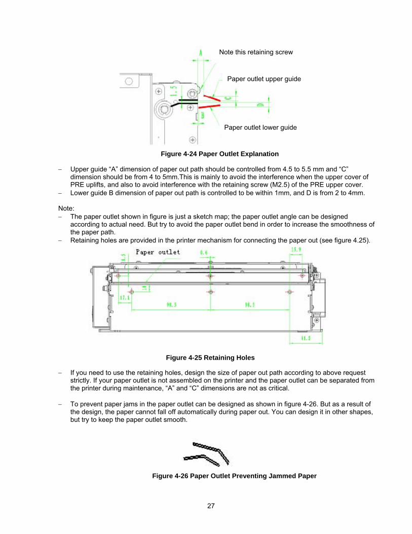
− Upper guide “A” dimension of paper out path should be controlled from 4.5 to 5.5 mm and “C” dimension should be from 4 to 5mm.This is mainly to avoid the interference when the upper cover of PRE uplifts, and also to avoid interference with the retaining screw (M2.5) of the PRE upper cover.
− Lower guide B dimension of paper out path is controlled to be within 1mm, and D is from 2 to 4mm.
Note: − The paper outlet shown in figure is just a sketch map; the paper outlet angle can be designed
according to actual need. But try to avoid the paper outlet bend in order to increase the smoothness of the paper path.
− Retaining holes are provided in the printer mechanism for connecting the paper out (see figure 4.25).
− If you need to use the retaining holes, design the size of paper out path according to above request strictly. If your paper outlet is not assembled on the printer and the paper outlet can be separated from the printer during maintenance, “A” and “C” dimensions are not as critical.
− To prevent paper jams in the paper outlet can be designed as shown in figure 4-26. But as a result of
the design, the paper cannot fall off automatically during paper out. You can design it in other shapes, but try to keep the paper outlet smooth.
Figure 4-25 Retaining Holes
Figure 4-26 Paper Outlet Preventing Jammed Paper
Figure 4-24 Paper Outlet Explanation
Note this retaining screw
Paper outlet upper guide
Paper outlet lower guide
28
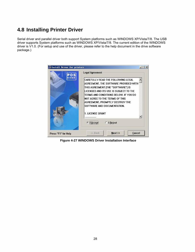
4.8 Installing Printer Driver Serial driver and parallel driver both support System platforms such as WINDOWS XP/Vista/7/8. The USB driver supports System platforms such as WINDOWS XP/Vista/7/8. The current edition of the WINDOWS driver is V1.0. (For setup and use of the driver, please refer to the help document in the drive software package.)
Figure 4-27 WINDOWS Driver Installation Interface
29
5 Routine Maintenance
Caution: − Make sure that the power is turned off before starting routine maintenance.
− Do not touch the printhead, platen roller, or sensors with sharp objects they may scratch.
− Do not clean any components of the printer with strong solvents such as gasoline, acetone,
etc.
− Use only isopropyl alcohol or other Microcom Corporation approved cleaners on the print head.
− Be sure to do follow a monthly maintenance routine (more, if printer use is severe).
5.1 Cleaning Print head The print head should be cleaned whenever the following circumstances occur:
• Print is not clear.
• Some columns are missing or are not clear.
• Paper feed is not smooth through the print head / platen roller area. To clean the print head, follow the steps below:
• Turn off the power and open the upper cover.
• Lift the print head module and allow the print head to cool down if it has recently printed.
• Wipe off the surface of the print head with a soft cotton cloth dampened with isopropyl alcohol.
• Allow isopropyl alcohol to evaporate and press print head module and close upper cover.
5.2 Cleaning sensors 5.2.1 Cleaning paper end sensor
The paper end sensor should be cleaned whenever the following circumstances occur:
• Printing stops and falsely signals paper end when there is still paper in the printer.
• The printer does not signal paper end when paper runs out during printing.
• The printer skips or incorrectly reads registration marks.
30
To clean the paper sensor, follow the steps below: • Turn off the power and open the upper cover. • Lift the print head to access the paper end sensor (see figure 3-7).
• Wipe off dust and stains on the surface of the paper end sensor with a soft cotton cloth dampened
with isopropyl alcohol.
• Allow isopropyl alcohol to evaporate, press print head module and close upper cover.
5.2.2 Cleaning paper loading sensor
The paper end sensor should be cleaned whenever the following circumstances occur:
• The paper does not retract back to normal printing position during semi-automatic paper loading.
• Print motor runs in reverse direction for an abnormally long time during semi-automatic paper loading.
• The paper does not retract to normal printing position after printing.
To clean the paper loading sensor, follow the steps below:
• Turn off the power and open the upper cover.
• Lift the print head to access the paper loading sensor (see figure 3-7).
• Wipe off dust and stains on the surface of the paper loading sensor with a soft cotton cloth dampened with isopropyl alcohol.
• Allow isopropyl alcohol to evaporate, press print head module and close upper cover.
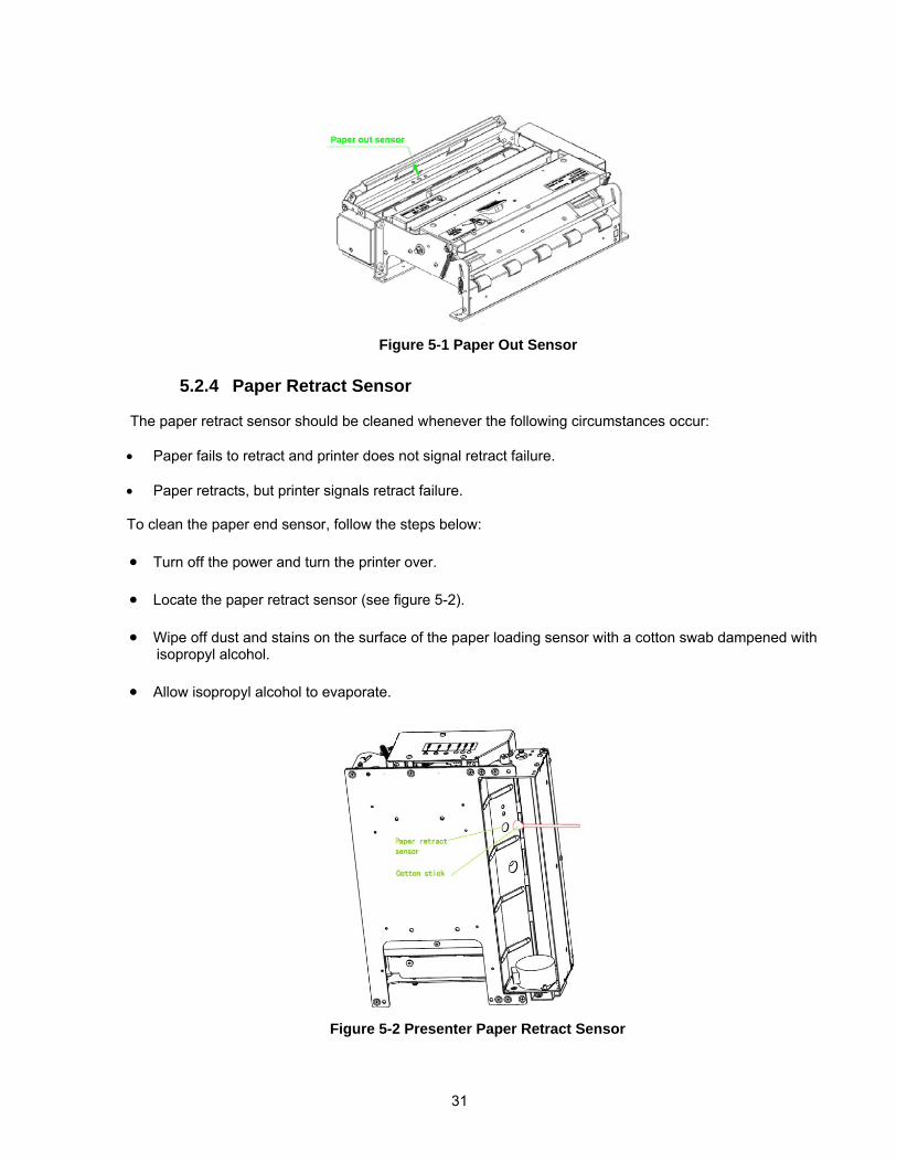
5.2.3 Cleaning paper out sensor
The paper out sensor should be cleaned whenever the following circumstances occur:
• PRESENTER cannot hold paper normally.
• PRESENTER cannot perform retracting function normally.
To clean the paper end sensor, follow the steps below: • Turn off the power and open the PRESENTER upper cover. • Locate paper out sensor (see figure 5-1).
• Wipe off dust and stains on the surface of the paper loading sensor with a soft cotton cloth dampened
with isopropyl alcohol.
• Allow isopropyl alcohol to evaporate, press print head module and close upper cover.
31
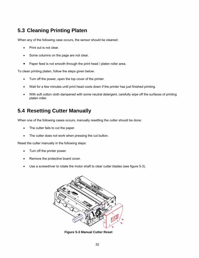
5.2.4 Paper Retract Sensor
The paper retract sensor should be cleaned whenever the following circumstances occur:
• Paper fails to retract and printer does not signal retract failure.
• Paper retracts, but printer signals retract failure.
To clean the paper end sensor, follow the steps below:
• Turn off the power and turn the printer over. • Locate the paper retract sensor (see figure 5-2).
• Wipe off dust and stains on the surface of the paper loading sensor with a cotton swab dampened with
isopropyl alcohol.
• Allow isopropyl alcohol to evaporate.
Figure 5-1 Paper Out Sensor
Figure 5-2 Presenter Paper Retract Sensor
32
5.3 Cleaning Printing Platen When any of the following case occurs, the sensor should be cleaned:
• Print out is not clear.
• Some columns on the page are not clear.
• Paper feed is not smooth through the print head / platen roller area. To clean printing platen, follow the steps given below:
• Turn off the power, open the top cover of the printer.
• Wait for a few minutes until print head cools down if the printer has just finished printing.
• With soft cotton cloth dampened with some neutral detergent, carefully wipe off the surfaces of printing platen roller.
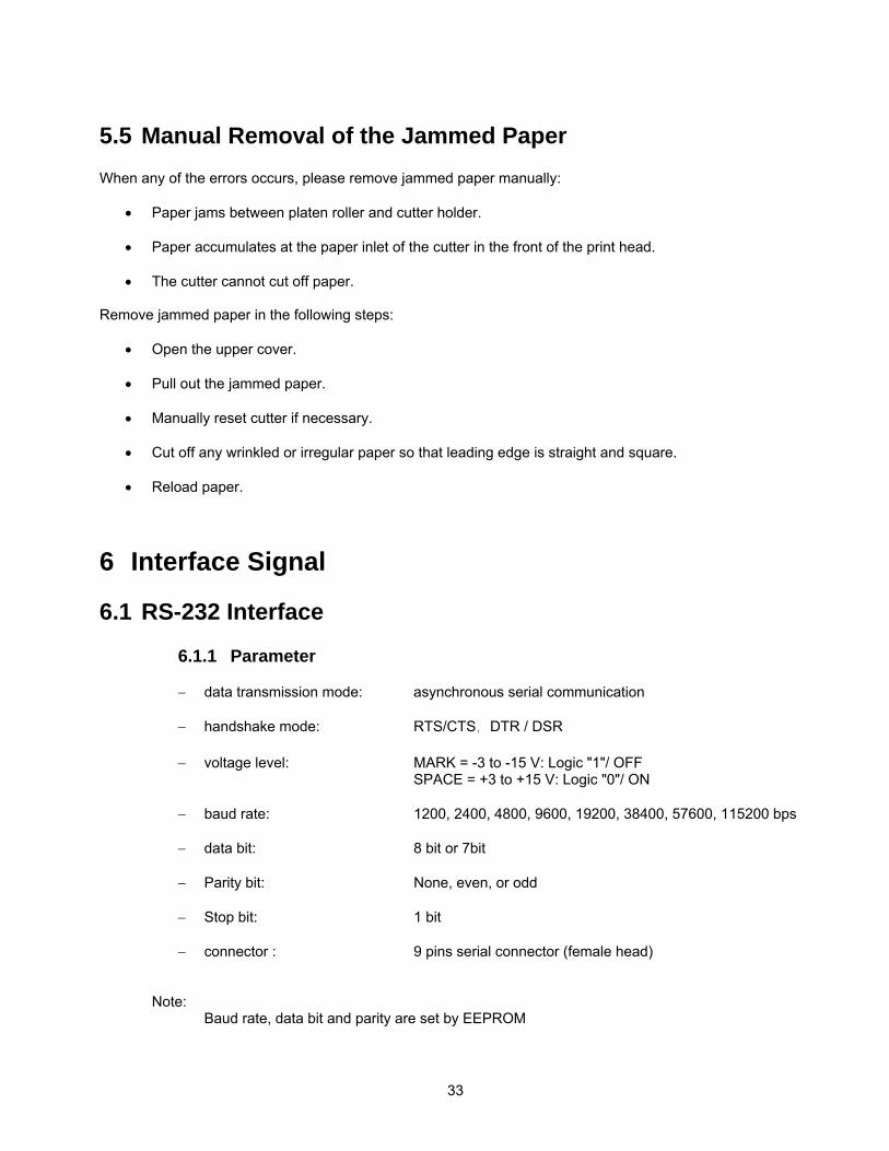
5.4 Resetting Cutter Manually When one of the following cases occurs, manually resetting the cutter should be done:
• The cutter fails to cut the paper.
• The cutter does not work when pressing the cut button.
Reset the cutter manually in the following steps:
• Turn off the printer power.
• Remove the protective board cover.
• Use a screwdriver to rotate the motor shaft to clear cutter blades (see figure 5-3).
Figure 5-3 Manual Cutter Reset
33
5.5 Manual Removal of the Jammed Paper When any of the errors occurs, please remove jammed paper manually:
• Paper jams between platen roller and cutter holder.
• Paper accumulates at the paper inlet of the cutter in the front of the print head.
• The cutter cannot cut off paper. Remove jammed paper in the following steps:
• Open the upper cover.
• Pull out the jammed paper.
• Manually reset cutter if necessary.
• Cut off any wrinkled or irregular paper so that leading edge is straight and square.
• Reload paper.
6 Interface Signal
6.1 RS-232 Interface
6.1.1 Parameter
− data transmission mode: asynchronous serial communication
− handshake mode: RTS/CTS, DTR / DSR
− voltage level: MARK = -3 to -15 V: Logic "1"/ OFF SPACE = +3 to +15 V: Logic "0"/ ON
− baud rate: 1200, 2400, 4800, 9600, 19200, 38400, 57600, 115200 bps
− data bit: 8 bit or 7bit
− Parity bit: None, even, or odd
− Stop bit: 1 bit
− connector : 9 pins serial connector (female head)
Note: Baud rate, data bit and parity are set by EEPROM
34
6.1.2 RS-232 Serial Interface Signals Printer serial port signals and status are described in the following table:
6.2 IEEE 1284 Parallel Interface (optional)
6.2.1 Parameters
− Data transmission: 8 bits Parallel
− Synchronization mode: nStrobe signal is provided by exterior
− Handshake mode: Busy signal
− Signal voltage level: TTL compatible
− Connector: 36 pin – Centronics
6.2.2 Parallel Interface Printer Status (/FAULT pin and PE pin)
PIN NO Signal name
Signal direction function
1 NO 2 RXD input Data input end
3 TXD output Data output end
4 DTR output Data terminal is ready
5 SG — Signal ground
6 DSR input Data device is ready
7 RTS output Request to send
8 CTS input Allow to send
9 FG — Frame Ground
Table 6-1 Serial Interface Signals
Status /FAULT PE
Normal high low
Paper end low high
Print head Overheated low low
Other errors low low
Table 6-2 /FAULT Pin and PE Explanation
35
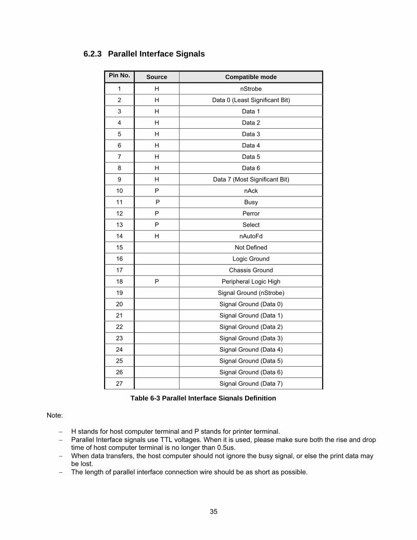
6.2.3 Parallel Interface Signals Note:
− H stands for host computer terminal and P stands for printer terminal. − Parallel Interface signals use TTL voltages. When it is used, please make sure both the rise and drop
time of host computer terminal is no longer than 0.5us. − When data transfers, the host computer should not ignore the busy signal, or else the print data may
be lost. − The length of parallel interface connection wire should be as short as possible.
Pin No. Source Compatible mode
1 H nStrobe
2 H Data 0 (Least Significant Bit)
3 H Data 1
4 H Data 2
5 H Data 3
6 H Data 4
7 H Data 5
8 H Data 6
9 H Data 7 (Most Significant Bit)
10 P nAck
11 P Busy
12 P Perror
13 P Select
14 H nAutoFd
15 Not Defined
16 Logic Ground
17 Chassis Ground
18 P Peripheral Logic High
19 Signal Ground (nStrobe)
20 Signal Ground (Data 0)
21 Signal Ground (Data 1)
22 Signal Ground (Data 2)
23 Signal Ground (Data 3)
24 Signal Ground (Data 4)
25 Signal Ground (Data 5)
26 Signal Ground (Data 6)
27 Signal Ground (Data 7)
Table 6-3 Parallel Interface Signals Definition
36
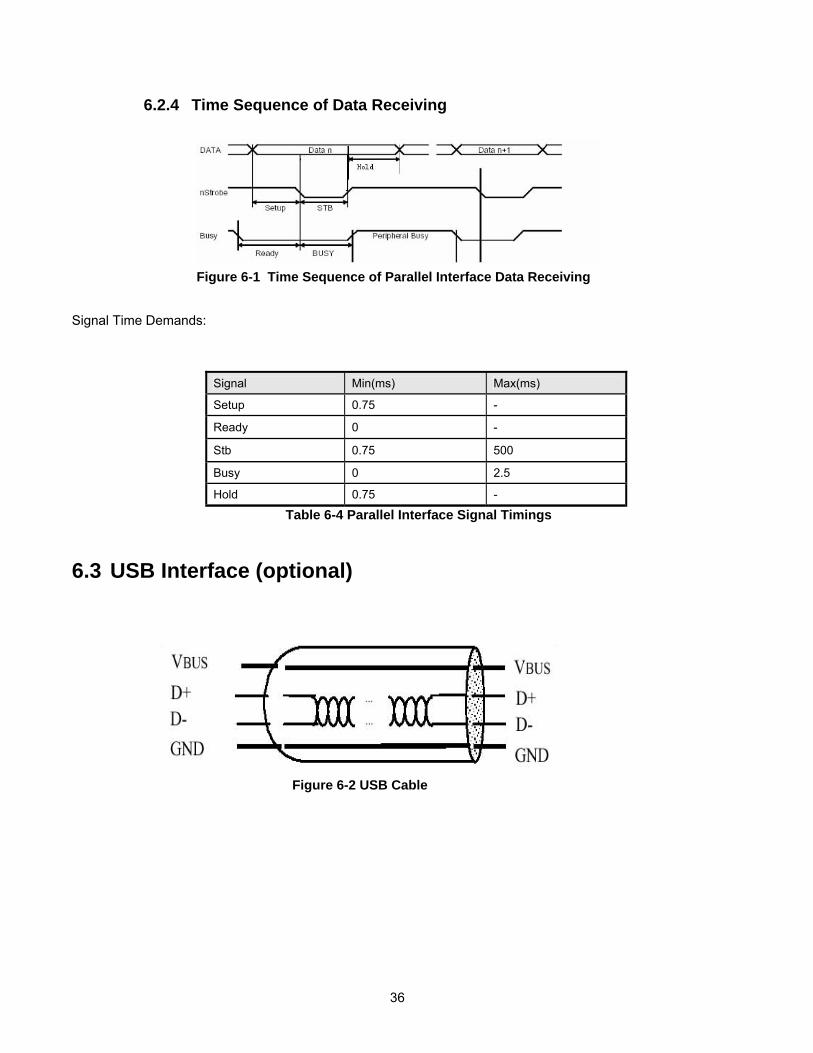
6.2.4 Time Sequence of Data Receiving Signal Time Demands:
6.3 USB Interface (optional)
Figure 6-1 Time Sequence of Parallel Interface Data Receiving
Signal Min(ms) Max(ms)
Setup 0.75 -
Ready 0 -
Stb 0.75 500
Busy 0 2.5
Hold 0.75 -
Table 6-4 Parallel Interface Signal Timings
Figure 6-2 USB Cable
37
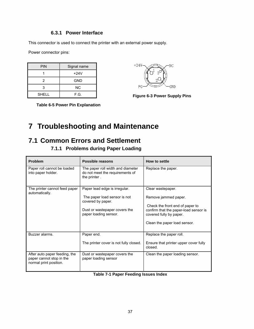
6.3.1 Power Interface This connector is used to connect the printer with an external power supply. Power connector pins:
Table 6-5 Power Pin Explanation
7 Troubleshooting and Maintenance
7.1 Common Errors and Settlement 7.1.1 Problems during Paper Loading
Problem Possible reasons How to settle
Paper roll cannot be loaded into paper holder.
The paper roll width and diameter do not meet the requirements of the printer .
Replace the paper.
The printer cannot feed paper automatically.
Paper lead edge is irregular. The paper load sensor is not covered by paper. Dust or wastepaper covers the paper loading sensor.
Clear wastepaper. Remove jammed paper. Check the front end of paper to confirm that the paper-load sensor is covered fully by paper. Clean the paper load sensor.
Buzzer alarms. Paper end. The printer cover is not fully closed.
Replace the paper roll. Ensure that printer upper cover fully closed.
After auto paper feeding, the paper cannot stop in the normal print position.
Dust or wastepaper covers the paper loading sensor
Clean the paper loading sensor.
Table 7-1 Paper Feeding Issues Index
Figure 6-3 Power Supply Pins
PIN Signal name
1 +24V
2 GND
3 NC
SHELL F.G.

38
7.1.2 Problems during Printing
Problems Possible reasons How to deal with
The receipt cannot be ejected out smoothly.
Paper jams. Open upper cover and presenter upper cover, check paper path, remove wastepaper and reload paper automatically.
Printout is not clear The thermal paper is loaded in wrong direction or of poor quality. Print head needs cleaning. Printing darkness is too low. Input voltage is too low.
Make sure the paper roll is loaded correctly. Use recommended paper or its equivalents. Adjust print darkness(*). Use the recommended power supply.
Cutter works abnormally Paper jams in cutter. Cutter is broken
Check if there is paper jammed in cutter path (*) Contact the manufacturer or your local distributor.
Printer does not print. The printer cover is closed improperly. Paper jams.
Close printer upper cover properly. Remove paper jam
Table 7-2 Print Issues Index ∗ Contact a distributor or manufacturer to adjust print darkness
7.1.3 Problems during Paper Out
Problems Possible reasons How to deal with
The printer stops printing and warns of errors during printing.
Paper end. Paper jams in cutter. Dust or wastepaper covers the paper near end sensor.
Install a new paper roll. Check if there is paper debris in cutter path. Clean the paper end sensor.
Table 7-3 Out of Paper Issues Index
39
7.1.4 Other Problems Problem Possible reasons How to deal with
No power LED and printer does not work.
The printer is not connected to the power supply correctly. The printer isn’t turned on.
Connect the printer to the power supply correctly. Turn on the printer.
The printer does not work after receiving commands.
Printer is in error status. The communication cable is not connected well. Interface settings are wrong.
Remove all errors (*). Make sure the communication cable is connected correctly. Print a self-test page and set the interface according to information on it.
∗ Paper near end alert acts only as a prompt for users, not as an error status. A print format can still be sent during a paper near end alert. ∗ If there is a jam in the cutter, first clear paper from cutter and then press the cutter button to reset the cutter.
40
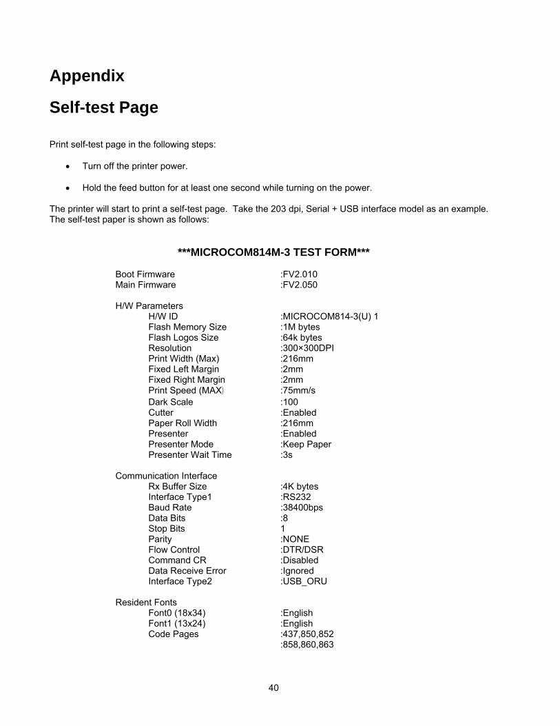
Appendix Self-test Page Print self-test page in the following steps:
• Turn off the printer power.
• Hold the feed button for at least one second while turning on the power. The printer will start to print a self-test page. Take the 203 dpi, Serial + USB interface model as an example. The self-test paper is shown as follows:
***MICROCOM814M-3 TEST FORM*** Boot Firmware :FV2.010 Main Firmware :FV2.050 H/W Parameters H/W ID :MICROCOM814-3(U) 1 Flash Memory Size :1M bytes Flash Logos Size :64k bytes Resolution :300×300DPI Print Width (Max) :216mm Fixed Left Margin :2mm Fixed Right Margin :2mm Print Speed (MAX) :75mm/s Dark Scale :100 Cutter :Enabled Paper Roll Width :216mm Presenter :Enabled Presenter Mode :Keep Paper Presenter Wait Time :3s Communication Interface Rx Buffer Size :4K bytes Interface Type1 :RS232 Baud Rate :38400bps Data Bits :8 Stop Bits 1 Parity :NONE Flow Control :DTR/DSR Command CR :Disabled Data Receive Error :Ignored Interface Type2 :USB_ORU Resident Fonts Font0 (18x34) :English Font1 (13x24) :English Code Pages :437,850,852 :858,860,863
41
:865,866,1252 :Katakana International Character :U.S.A. :France ;Germany :U.K. :Denmark l :Italy :Spain I :Japan :Norway :Denmark ll :Spain ll :Latin America Bar Code Available :UPC-A :UPC-E :EAN-8 :EAN-13 :CODE 39 :CODE 93 :ITF :CODABAR :CODE128 :PDF417 Explanation of self-test page content: Boot Firmware Printer BOOTLOADER version Main Printer monitor program version H/W Parameters Printer parameter setting H/W ID Printer ID setting Flash Memory Size Printer FLASH size Flash Logos Size Flash size for bitmap downloading Resolution Printer resolution Valid Print Width(Max) Maximum print width Fixed Left Margin Fixed left margin setting Fixed Right Margin Fixed right margin setting PrintSpeed(MAX) Print speed Dark Scale Print darkness Cutter Enable/ Disable cutter Paper Roll Width (MAX) Maximum width of paper roll PRSENTER Enable/Disable PRESENTER PRSENTER Mode PRESENTER paper out mode PRESENTER WAIT TIME Time print is presented before retraction Comm Interface Communication interface setting Rx Buffer Size Data receiving buffer zone size Interface Type Interface type Baud Rate Serial communication baud rate setting Data Bit Serial communication data bit setting Stop Bit Serial communication stop bit setting Parity Serial communication parity bit setting Handshaking Serial communication data stream mode (handshaking type) Command CR Enable/Disable CR command Data Received Error Serial receive error Interface Type2 The second interface type Resident Fonts Font setting

42
Font 0(18×34) Font 0 setting Font 1(13×24) Font 1 setting Code Pages Code page type International Character International Character type BarCode Available Printable Barcode types


![MODEL 814M DIRECT THERMAL PRINTER PROGRAMMING … · 2014. 4. 1. · 6 2. Kiosk Command Set HT [Name] [Format] [Description] [Notes] [Default] [Reference] Horizontal tab. ASCII HT](https://img.pdfslide.net/doc/110x75/607f029e60b69f32996197f0/model-814m-direct-thermal-printer-programming-2014-4-1-6-2-kiosk-command-set.jpg)