Embed Size (px)
Citation preview

MN-29756 (R e v . 4 ) • 10/16p R i N t e d i N u . s . a .
Model:
500-TH-II750-TH-II1000-TH-I1000-TH-II
767-SK1767-SK1000-SK-I1000-SK/II
• INSTALLATION
• OPERATION
• MAINTENANCE
W164 N9221 Water Street • P.O. Box 450Menomonee Falls, Wisconsin 53052-0450 U.S.A.
PHONE: 262.251.3800 • 800.558.8744 U.S.A. / CANADAFAX: 262.251.7067 • 800.329.8744 U.S.A. ONLY
www.alto-shaam.comConsult instructions
for operation and use.
1000-SK-I Sown with optional burgundy exterior
1000-TH-I
1000-TH-II
500-TH-II
1767-SK767-SK
Cook, Hold, Smoke Oven
Manual Control
MN-29756 (Rev. 4) 10/16 • TH-SK Series Cook, Hold, Smoke
Delivery . . . . . . . . . . . . . . . . . . . . . . . . . . . . . . . . . . . . . . . . . 1Unpacking . . . . . . . . . . . . . . . . . . . . . . . . . . . . . . . . . . . . . . . 1Safety Procedures and Precautions . . . . . . . . . . . . . . . . . . . . 2
InstallationInstallation Requirements . . . . . . . . . . . . . . . . . . . . . . . . 4Clearance Requirements . . . . . . . . . . . . . . . . . . . . . . . . . 4Dimension Drawings, weights & capacities . . . . . . . . . . . 5Options and Accessories . . . . . . . . . . . . . . . . . . . . . . . . 9Stacking Configurations . . . . . . . . . . . . . . . . . . . . . . . . 11Leveling . . . . . . . . . . . . . . . . . . . . . . . . . . . . . . . . . . . . 12Restraint Requirements - Mobile Equipment . . . . . . . . . 12Drip Tray Installation . . . . . . . . . . . . . . . . . . . . . . . . . . . 13Electrical Specifications . . . . . . . . . . . . . . . . . . . . . . . . 14
Operating InstructionsUser Safety Information . . . . . . . . . . . . . . . . . . . . . . . . 16Start-up Operation . . . . . . . . . . . . . . . . . . . . . . . . . . . . 16Cook/Hold/Smoke Instructions . . . . . . . . . . . . . . . . . . . 17General Holding Guidelines . . . . . . . . . . . . . . . . . . . . . . 19
Care and CleaningCare and Cleaning Instructions . . . . . . . . . . . . . . . . . . . 20Preventative Maintenance Checklist . . . . . . . . . . . . . . . 22
SanitationFood Safety . . . . . . . . . . . . . . . . . . . . . . . . . . . . . . . . . 23Internal Food Product Temperatures . . . . . . . . . . . . . . . 23
ServiceTroubleshooting - Error Codes . . . . . . . . . . . . . . . . . . . 25Cook & Hold - 500, 750, 1000-TH-II Service Views . . . . . . . . . . . . . . 26 1000-TH-I Service Views . . . . . . . . . . . . . . . . . . . . . . . 28 Electronic Components . . . . . . . . . . . . . . . . . . . . . . . . 30Cook, Hold, Smoke - 767-SK, 1000-SK/II Service Views . . . . . . . . . . . . . . . 31 1000-SK-I Service Views . . . . . . . . . . . . . . . . . . . . . . 33 Electrical Components . . . . . . . . . . . . . . . . . . . . . . . . 35
Wire DiagramsAlways refer to the wire diagram(s) included with the unit for most current version .
WarrantyTransportation Damage and Claims . . . . . . . . Back CoverLimited Warranty . . . . . . . . . . . . . . . . . . . . . . Back Cover
MN-29756 (Rev . 4) 10/16 • TH-SK Series Cook, Hold, Smoke • 1
Del i very
This Alto-Shaam appliance has been thoroughly tested and inspected to ensure only the highest quality unit is provided. Upon receipt, check for any possible shipping damage and report it at once to the delivering carrier. See Transportation Damage and Claims section located in this manual.
This appliance, complete with unattached items and accessories, may be delivered in one or more packages. Ensure all standard items and options have been received with each model as ordered.
Save all the information packed with the appliance. Register online at www.alto-shaam.com to ensure prompt service in the event of a warranty parts and labor claim.
This manual must be read and understood by all people using or installing the equipment model. Contact the Alto-Shaam Tech Team Service Department if you have any questions concerning installation, operation, or maintenance.
1-800-558-8744; [email protected]
Unpack ing
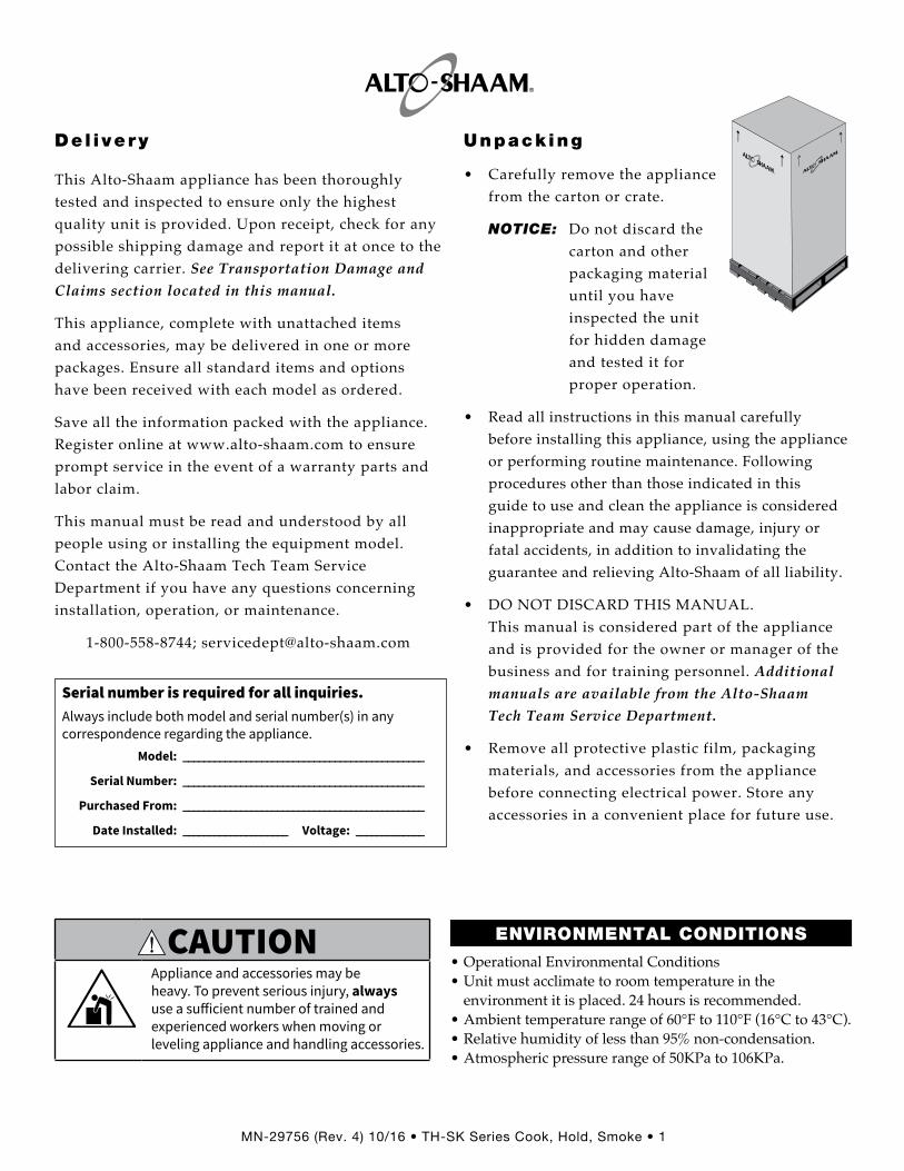
• Carefully remove the appliance from the carton or crate.
NOTICE: Do not discard the carton and other packaging material until you have inspected the unit for hidden damage and tested it for proper operation.
• Read all instructions in this manual carefully before installing this appliance, using the appliance or performing routine maintenance. Following procedures other than those indicated in this guide to use and clean the appliance is considered inappropriate and may cause damage, injury or fatal accidents, in addition to invalidating the guarantee and relieving Alto-Shaam of all liability.
• DO NOT DISCARD THIS MANUAL. This manual is considered part of the appliance and is provided for the owner or manager of the business and for training personnel. Additional manuals are available from the Alto-Shaam Tech Team Service Department.
• Remove all protective plastic film, packaging materials, and accessories from the appliance before connecting electrical power. Store any accessories in a convenient place for future use.
®
®
CAUTIONAppliance and accessories may be heavy. To prevent serious injury, always use a su� icient number of trained and experienced workers when moving or leveling appliance and handling accessories.
ENVIRONMENTAL CONDITIONS
• Operational Environmental Conditions• Unit must acclimate to room temperature in the
environment it is placed. 24 hours is recommended.• Ambient temperature range of 60°F to 110°F (16°C to 43°C).• Relative humidity of less than 95% non-condensation.• Atmospheric pressure range of 50KPa to 106KPa.
Serial number is required for all inquiries.Always include both model and serial number(s) in any correspondence regarding the appliance. Model: ______________________________________________
Serial Number: ______________________________________________
Purchased From: ______________________________________________
Date Installed: ____________________ Voltage: _____________
Delivery Unpacking

MN-29756 (Rev . 4) 10/16 • TH-SK Series Cook, Hold, Smoke • 2
CAUTIONUsed to indicate the presence of a hazard that can or will cause minor personal injury, property damage, or a potential unsafe practice if the warning included with this symbol is ignored.
CAUTIONUsed to indicate the presence of a hazard that can or will cause minor or moderate personal injury or property damage if the warning included with this symbol is ignored.
DANGERUsed to indicate the presence of a hazard that WILL cause severe personal injury, death, or substantial property damage if the warning included with this symbol is ignored.
WARNINGUsed to indicate the presence of a hazard that CAN cause personal injury, possible death, or major property damage if the warning included with this symbol is ignored.
• This appliance is intended to cook, hold or process foods for the purpose of human consumption. No other use for this appliance is authorized and is therefore considered dangerous. The appliance must not be used to cook food containing flammable materials (such as food with alcohol). Substances with a low flash point can ignite spontaneously and cause a fire.
• This appliance is intended for use in commercial establishments where all operators are familiar with the purpose, limitations, and associated hazards of this appliance. Operating instructions and warnings must be read and understood by all operators and users. We recommend regular training of your staff to avoid the risk of accident or damage to the unit. Operators must also receive regular safety instructions.
• Any trouble shooting guides, component views, and parts lists included in this manual are for general reference only and are intended for use by qualified and trained technicians.
• This manual should be considered a permanent part of this appliance. This manual and all supplied instructions, diagrams, schematics, parts lists, notices, and labels must remain with the appliance if the item is sold or moved to another location.
NOTICE: Used to notify personnel of installation, operation, or maintenance information that is important but not hazard related.
Safety Proceduresand Precautions
Knowledge of proper procedures is essential to the safe operation of electrically and/or gas energized equipment. The following hazard signal words and symbols may be used throughout this manual.
Used to indicate that referral to operating instructions is a mandatory action. If not followed the operator could suffer personal injury.
Used to indicate that referral to operating instructions is recommended to understand operation of equipment.
NOTICE: For equipment delivered for use in any location regulated by the following directive: 2012/95/EC WEEE
DO NOT dispose of electrical or electronic equipment with other municipal waste.
Safety Procedures and Precautions
MN-29756 (Rev . 4) 10/16 • TH-SK Series Cook, Hold, Smoke • 3
• To prevent serious injury, death or property damage, your appliance should be inspected and serviced at least every twelve (12) months by an authorized service partner or trained technician.
• ONLY allow an authorized service partner or trained technician to service or to repair your appliance. Installation or repairs that are not performed by an authorized service partner or trained technician, or the use of non-factory authorized parts will void the warranty and relieve Alto-Shaam of all liability.
• When working on this appliance, observe precautions in the literature, on tags, on labels attached to or shipped with the appliance and other safety precautions that may apply.
• If the appliance is installed on casters freedom of movement of the appliance must be restricted so that utility connections (including gas, water, and electricity) cannot be damaged when the unit is moved. If the appliance is moved, make sure that all utility connections are properly disconnected. If the unit is returned to its original position, make sure that any retention devices and utility connections are properly connected.
• ONLY use the appliance when it is stationary. Mobile oven racks, mobile plate racks, transport trolleys, and appliances on casters can tip over when being moved over an uneven floor or threshold and cause serious injury.
• ALWAYS apply caster brakes on mobile appliances or accessories when these are not being moved. These items could move or roll on uneven floors and cause property damage or serious injury.
• Be extremely careful when moving appliances because the food trays may contain hot fluids that may spill, causing serious injury.
• ALWAYS open the appliance door very slowly. Escaping hot vapors or steam can cause serious injury or death.
Additional Safety Procedures and Precautions
• If your gas appliance is installed under an exhaust hood, the hood must be switched ON when the oven is in use to avoid the build up of combustion gases. Failure to do so may result in serious injury, death or property damage.
• NEVER place objects near the oven exhaust vents. This area is hot and could be a potential ignition source for a fire.
• Do not allow objects to block or obstruct the area below the oven base. This may result in fire, damage to the equipment or serious injury.
• Do not use the attached hand-held hose to spray anything other than the interior of the oven compartment.
• Do not use the attached hand-held hose on the surface of a hot cooking compartment. The sudden temperature change can damage the oven interior. Allow the oven to cool to a minimum of 150°F (66°C). Failure to observe this precaution can void the warranty.
WARNINGTo prevent serious personal injury, death, or property damage:
The appliance must be cleaned thoroughly to avoid deposits of grease and or food residues inside the appliance that may catch fire. If fat deposits and/or food waste inside the appliance ignite, shut down the appliance immediately and keep the appliance door closed to extinguish the fire. If further extinguishing is required, disconnect the appliance from the main power and use a fire extinguisher (do not use water to extinguish a grease fire!). Failure to clean the appliance properly invalidates the warranty and relieves Alto-Shaam of all liability.
WARNINGThis appliance is not intended for use by persons (including children) with reduced physical, sensory or mental capabilities, or lack of experience and knowledge, unless they have been given supervision concerning use of the appliance by person responsible for their safety.
Children should be supervised to ensure that they do not play with the appliance.
MN-29756 (Rev . 4) 10/16 • TH-SK Series Cook, Hold, Smoke • 4
S ITE INSTALLATION
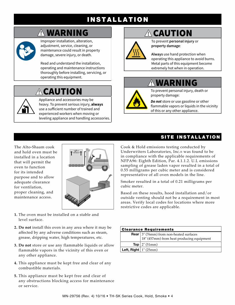
The Alto-Shaam cook and hold oven must be installed in a location that will permit the oven to function for its intended purpose and to allow adequate clearance for ventilation, proper cleaning, and maintenance access.
1. The oven must be installed on a stable and level surface.
2. Do not install this oven in any area where it may be affected by any adverse conditions such as steam, grease, dripping water, high temperatures, etc.
3. Do not store or use any flammable liquids or allow flammable vapors in the vicinity of this oven or any other appliance.
4. This appliance must be kept free and clear of any combustible materials.
5. This appliance must be kept free and clear of any obstructions blocking access for maintenance or service.
®
INSTALLATION
Cook & Hold emissions testing conducted by Underwriters Laboratories, Inc.® was found to be in compliance with the applicable requirements of NFPA96: Eighth Edition, Par. 4.1.1.2. U.L emissions sampling of grease laden vapor resulted in a total of 0.55 milligrams per cubic meter and is considered representative of all oven models in the line.
Smoker resulted in a total of 0.21 milligrams per cubic meter.
Based on these results, hood installation and/or outside venting should not be a requirement in most areas. Verify local codes for locations where more restrictive codes are applicable.
WARNINGImproper installation, alteration, adjustment, service, cleaning, or maintenance could result in property damage, severe injury, or death.
Read and understand the installation, operating and maintenance instructions thoroughly before installing, servicing, or operating this equipment.
CAUTIONAppliance and accessories may be heavy. To prevent serious injury, always use a su� icient number of trained and experienced workers when moving or leveling appliance and handling accessories.
CAUTIONTo prevent personal injury or property damage:
Always use hand protection when operating this appliance to avoid burns. Metal parts of this equipment become extremely hot when in operation.
W017Warning; Hot surface
WARNINGTo prevent personal injury, death or property damage:
Do not store or use gasoline or other flammable vapors or liquids in the vicinity of this or any other appliance.
Installation Installation Requirements Clearance Requirements
Clearance RequirementsRear 3" (76mm) from non-heated surfaces
18" (457mm) from heat producing equipmentTop 2" (51mm)
Left, Right 1" (25mm)

MN-29756 (Rev . 4) 10/16 • TH-SK Series Cook, Hold, Smoke • 5
21" (532mm)
Shown with optional bumper
29-7
/8"
(758
mm
)
41-1
/16"
(10
43m
m)
Electrical Connection
44-1
/16"
(11
18m
m)
58-1
/4"
(147
9mm
)
28-1
3/16
" (7
32m
m)
21-7/8" (556mm)16" (406mm)
31-7
/8"
(809
mm
)w
ith 2
-1/2
" (6
4mm
) ca
ster
s*
3-5/
8" (
91m
m)
18-1/16" (458mm)
Pass-ThroughOption
Pass-ThroughOption
19" (483mm)
Electrical Connection
26-3/8" (670mm)
*33-3/8" (848mm) - with optional 3-1/2" (89mm) casters*35-1/4" (894mm) - with optional 5" (127mm) casters*33-3/4" (857mm) - with optional 6" (152mm) legs
19-1/8" (486mm)14-1/2" (368mm)
29" (737mm)26-9/16" (675mm)
Electrical Connection
Cord Length120V - 5 ft. (1524mm)208-240V - 5 ft. (1524mm)230V - 8 ft. (2438mm)
Shown with optional bumper
Electrical Connection
Pass-ThroughOptionElectrical
Connection
Pass-ThroughOption
Electrical Connection
Shown with optional bumper
25-5/8" (651mm)
54-1
/8"
(137
3mm
)3-
5/8"
(91
mm
)
23-5/8" (600mm)26-5/8" (676mm)
28-1
3/16
" (7
32m
m)
24-1/8" (612mm)
17" (432mm)
34" (864mm)
31-5/8" (802mm)
28-9/16" (726mm)
79"
(200
6mm
)
34-7
/8"
(886
mm
)
*33-3/8" (848mm) - with optional 3-1/2" (89mm) casters*35-1/4" (894mm) - with optional 5" (127mm) casters*33-3/4" (857mm) - with optional 6" (152mm) legs
26-3/4" (679mm)
Cord Length120V - 5 ft. (1524mm)208-240V - 5 ft. (1524mm)230V - 8 ft. (2438mm)
31-7
/8"
(809
mm
)w
ith 2
-1/2
" (6
4mm
) ca
ster
s*
31-3/8" (797mm)
56-7
/8"
(144
4mm
)
500-TH-II 750-TH-II
S ITE INSTALLATION
INSTALLATION
Model > 500-TH-II 750-TH-II
Net Weight 130 lb (59 kg) 194 lb (88 kg)Ship Weight 166 lb (75 kg) 264 lb (120 kg)Product/Pan Capacity 40 lb (18kg) maximum
Volume maximum: 30 quarts (38 liters)100 lb (45kg) maximum
Volume maximum: 75 quarts (95 liters)
Dimension Drawings, weights & capacities
MN-29756 (Rev . 4) 10/16 • TH-SK Series Cook, Hold, Smoke • 6
S ITE INSTALLATION
INSTALLATION
34" (864mm)
25-1/16" (636mm)
22-1/2" (572mm) 17" (432mm)
51"
(129
4mm
)
72-3
/4"
(184
7mm
)
5-1/
8" (
130m
m)
40-3
/16"
(10
21m
m)
with
3-1
/2 (
89m
m)
cast
ers
37"
(940
mm
)
34-1
/2"
(876
mm
)
*38-5/8" (981mm) - with optional 2-1/2" casters*42" (1067mm) - with optional 5" casters*41-7/8" (1063mm) - with optional 6" legs
Electrical Connection
Pass-ThroughOption
Electrical Connection
20-1/2" (521mm)
23-1/2" (597mm)
31-5/8" (802mm)
26-7/8" (683mm)
Cord Length120V - 5 ft. (1524mm)230V - 8 ft. (2438mm)
23-5/8" (600mm)
Shown with optional bumper
Pass-ThroughOption
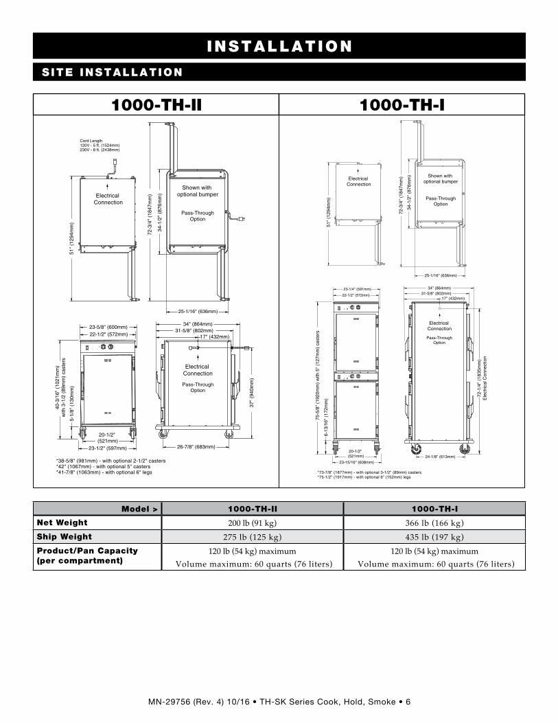
1000-TH-II
25-1/16" (636mm)
72-3
/4"
(184
7mm
)
34-1
/2"
(876
mm
)
51"
(129
4mm
)
Electrical Connection
*73-7/8" (1877mm) - with optional 3-1/2" (89mm) casters*75-1/2" (1917mm) - with optional 6" (152mm) legs
Pass-ThroughOption
Electrical Connection
34" (864mm)
17" (432mm)31-5/8" (802mm)22-1/2" (572mm)
20-1/2" (521mm)
23-15/16" (608mm)
6-13
/16"
(17
2mm
)
75-5
/8"
(192
0mm
) w
ith 5
" (1
27m
m)
cast
ers
72-1
/4"
(183
5mm
)E
lect
rical
Con
nect
ion
24-1/8" (613mm)
23-1/4" (591mm)
Shown with optional bumper
Pass-ThroughOption
1000-TH-I
Model > 1000-TH-II 1000-TH-I
Net Weight 200 lb (91 kg) 366 lb (166 kg)Ship Weight 275 lb (125 kg) 435 lb (197 kg)Product/Pan Capacity (per compartment)
120 lb (54 kg) maximumVolume maximum: 60 quarts (76 liters)
120 lb (54 kg) maximumVolume maximum: 60 quarts (76 liters)

MN-29756 (Rev . 4) 10/16 • TH-SK Series Cook, Hold, Smoke • 7
S ITE INSTALLATION
INSTALLATION
26-5/8" (676mm)
25-11/16" (651mm)
*31-11/16" (804mm) - with optional 2-1/2" casters*35-1/16" (890mm) - with optional 5" casters*33-13/16" (858mm) - with optional 6" legs
33-3
/8"
(848
mm
)w
ith 3
-1/2
" ca
ster
s*
28-5/8" (726mm)
Shown with optional bumper
34-7
/8"
(886
mm
)
56-3
/4"
(144
1mm
)
Electrical Connection
54-1
/16"
(13
73m
m)
11-5/8" (295mm)
31-5/8" (802mm)
30-3
/16"
(76
7mm
)(e
lect
rical
con
nect
ion)
24-1/8" (612mm) 23-5/8" (600mm)
5-1/
8" (
130m
m)
Cord Length120V - 5 ft. (1524mm)230V - 8 ft. (2438mm)
767-SK
27-1/16" (686mm)
25-11/16" (651mm)
23-5/8" (600mm)
Shown with optional bumper
Electrical Connection
28-5/8" (726mm)
34-7
/8"
(886
mm
)
56-3
/4"
(144
1mm
)
54-1
/16"
(13
73m
m)
11-5/8" (295mm)
31-3/4" (807mm)
24-1/8" (613mm)
58-9
/16"
(14
87m
m)
Ele
ctric
al C
onne
ctio
n
61-1
5/16
" (1
572m
m)
with
5"
(127
mm
) ca
ster
s*
6-13
/16"
(17
2mm
)
*60-11/16" (1540mm) - with optional 3-1/2" (89mm) casters*62-1/8" (1577mm) - with optional 6" (152mm) legs
32-3/4" (832mm)
1767-SK
Model > 767-SK 1767-SK
Net Weight 197 lb (89 kg) 356 lb (161 kg)Ship Weight 265 lb (120 kg) 450 lb (204 kg)Product/Pan Capacity (per compartment)
100 lb (45 kg) maximumVolume maximum: 53 quarts (67 liters)
100 lb (45 kg) maximumVolume maximum: 53 quarts (67 liters)

MN-29756 (Rev . 4) 10/16 • TH-SK Series Cook, Hold, Smoke • 8
S ITE INSTALLATION
INSTALLATION
25-1/16" (636mm)
22-1/2" (572mm)
51"
(129
4mm
)6-
13/1
6" (
172m
m)
34-1
/2"
(876
mm
)
Electrical Connection
32-1/4" (819mm)
Shown withoptional bumper
20-1/2" (521mm)
23-15/16" (608mm)
75-5
/8"
(192
0mm
) w
ith 5
(12
7mm
) ca
ster
s*
24-1/8" (613mm)
72-1
/4"
(183
5mm
) E
lect
rical
Con
nect
ion
*74-1/4" (1885mm) - with optional 3-1/2" (89mm) casters*75-1/2" (1917mm) - with optional 6" (152mm) legs
1000-SK-I
25-1/16" (636mm)
22-1/2" (572mm)
51"
(129
4mm
)5-
1/8"
(13
0mm
)
40-3
/16"
(10
21m
m)
with
3-1
/2 (
89m
m)
cast
ers
34-1
/2"
(876
mm
)
*38-1/2" (977mm) - with optional 2-1/2" casters*41-15/16" (1064mm) - with optional 5" casters*41-7/8" (1063mm) - with optional 6" legs
Electrical Connection
20-1/2" (521mm)
23-1/2" (597mm)
31-5/8" (802mm)
26-7/8" (683mm)
Cord Length230V - 8 ft. (2438mm)
37"
(940
mm
)
Shown withoptional bumper
1000-SK/II
Model > 1000-SK-I 1000-SK/II
Net Weight 377 lb (171 kg) 203 lb (92 kg) est.Ship Weight 445 lb (202 kg) est. 282 lb (101 kg) est.Product/Pan Capacity (per compartment)
120 lb (54 kg) maximumVolume maximum: 60 quarts (76 liters)
120 lb (54 kg) maximumVolume maximum: 60 quarts (76 liters)

MN-29756 (Rev . 4) 10/16 • TH-SK Series Cook, Hold, Smoke • 9
Model> 500-TH-II 750-TH-II 1000-TH-II 1000-TH-I
Bumper, Full PerimeterNot available with 2-1/2" (64mm) casters 5011161 5010371 5009767 5009767
Carving Holder, Prime rib
Steamship (cafeteria) roundHL-2635
4459HL-2635
4459HL-2635
4459HL-2635
4459
Casters - 2 rigid, 2 swivel w/brake5" (127mm)
3-1/2" (89mm) 2-1/2" (64mm)
5004862 5008017
staNdaRd
5004862 5008017
staNdaRd
5004862 staNdaRd 5008022
staNdaRd 5008017
—
Door with WindowRight-hand
Left-hand5010830 5010829
5010948 5010949
5010082 5010076
5010082 5010076
Door Lock with Key LK-22567 LK-22567 LK-22567 LK-22567
Drip Pan 1-7/8" (48mm) deep with drain
1-11/16" (43mm) deep with drain 1-5/8" (41mm) deep without drain 1-7/8" (48mm) deep without drain
4" (102mm) extra deep
— 14831
1014684 — —
— 14831
1014684 — —
5005616 — —
11906 15929
5005616 — —
11906 15929
Legs, 6" (152mm), Flanged (set of four) 5011149 5011149 5011149 5011149
Pan Grid, Wire - 18" x 26" pan insert — PN-2115 PN-2115 PN-2115
Security Panel w/ Key Lock 5013939 5013936 5013934 5013935
Shelf, Stainless SteelStainless steel, flat wire, reach-in
Stainless steel, flat wire, pass-through Chrome, flat wire, pass-through
Rib rack
SH-2326 — — —
SH-2324 —
SH-2327 SH-2743
SH-2325 SH-2346
— SH-29474
SH-2325 SH-2346
— SH-29474
Stacking Hardware - Over or under TH, SK, or S-Series
Under XL-300 Xcelerate® Under XL-400 Xcelerate®
Under CTX4-10 Combitherm®
5004864 ———
5004864501967750196785019679
50048645019677
—5019679
————
INSTALLATIONCook & Hold Options and Accessories
Options and Accessories
MN-29756 (Rev . 4) 10/16 • TH-SK Series Cook, Hold, Smoke • 10
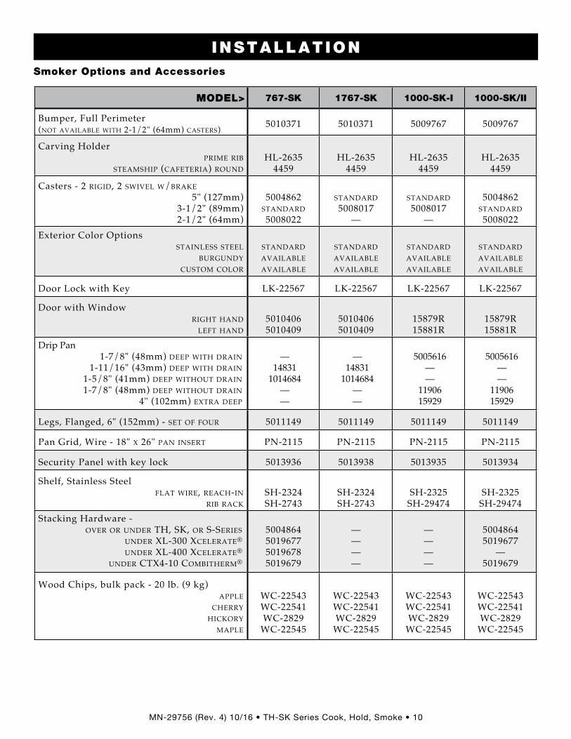
MODEL> 767-SK 1767-SK 1000-SK-I 1000-SK/II
Bumper, Full Perimeter (Not available with 2-1/2" (64mm) casteRs) 5010371 5010371 5009767 5009767
Carving HolderpRiMe Rib
steaMship (cafeteRia) RouNdHL-2635
4459HL-2635
4459HL-2635
4459HL-2635
4459
Casters - 2 Rigid, 2 swivel w/bRake5" (127mm)
3-1/2" (89mm) 2-1/2" (64mm)
5004862 staNdaRd 5008022
staNdaRd 5008017
—
staNdaRd5008017
—
5004862 staNdaRd 5008022
Exterior Color Options staiNless steel
buRguNdy custoM coloR
staNdaRd availableavailable
staNdaRd availableavailable
staNdaRd availableavailable
staNdaRd availableavailable
Door Lock with Key LK-22567 LK-22567 LK-22567 LK-22567
Door with WindowRight haNd
left haNd50104065010409
50104065010409
15879R15881R
15879R15881R
Drip Pan 1-7/8" (48mm) deep with dRaiN
1-11/16" (43mm) deep with dRaiN 1-5/8" (41mm) deep without dRaiN 1-7/8" (48mm) deep without dRaiN
4" (102mm) extRa deep
— 14831
1014684 — —
— 14831
1014684 — —
5005616 — —
11906 15929
5005616 — —
11906 15929
Legs, Flanged, 6" (152mm) - set of fouR 5011149 5011149 5011149 5011149
Pan Grid, Wire - 18" x 26" paN iNseRt PN-2115 PN-2115 PN-2115 PN-2115
Security Panel with key lock 5013936 5013938 5013935 5013934
Shelf, Stainless Steel flat wiRe, Reach-iN
Rib RackSH-2324 SH-2743
SH-2324 SH-2743
SH-2325SH-29474
SH-2325SH-29474
Stacking Hardware - oveR oR uNdeR th, sk, oR s-seRies
uNdeR xl-300 xceleRate® uNdeR xl-400 xceleRate®
uNdeR ctx4-10 coMbitheRM®
5004864 501967750196785019679
————
————
50048645019677
—5019679
Wood Chips, bulk pack - 20 lb. (9 kg) apple
cheRRy hickoRy
Maple
WC-22543 WC-22541 WC-2829
WC-22545
WC-22543 WC-22541 WC-2829
WC-22545
WC-22543 WC-22541 WC-2829
WC-22545
WC-22543 WC-22541 WC-2829
WC-22545
INSTALLATIONSmoker Options and Accessories
MN-29756 (Rev . 4) 10/16 • TH-SK Series Cook, Hold, Smoke • 11
S ITE INSTALLATION
INSTALLATION
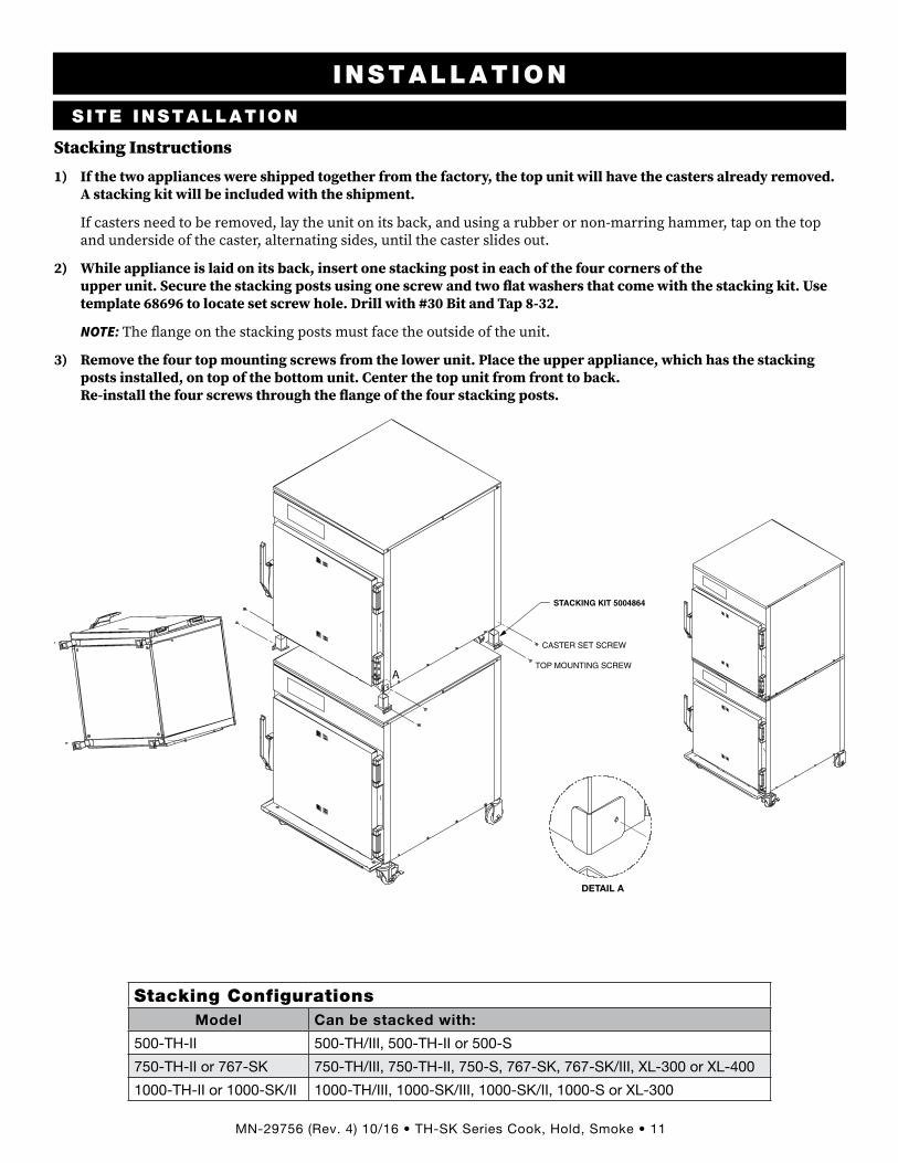
Stacking Instructions
1) If the two appliances were shipped together from the factory, the top unit will have the casters already removed. A stacking kit will be included with the shipment.
If casters need to be removed, lay the unit on its back, and using a rubber or non-marring hammer, tap on the top and underside of the caster, alternating sides, until the caster slides out.
2) While appliance is laid on its back, insert one stacking post in each of the four corners of the upper unit. Secure the stacking posts using one screw and two � at washers that come with the stacking kit. Use template 68696 to locate set screw hole. Drill with #30 Bit and Tap 8-32.
NOTE: The � ange on the stacking posts must face the outside of the unit.
3) Remove the four top mounting screws from the lower unit. Place the upper appliance, which has the stacking posts installed, on top of the bottom unit. Center the top unit from front to back. Re-install the four screws through the � ange of the four stacking posts.
DETAIL A
STACKING KIT 5004864
CASTER SET SCREW
TOP MOUNTING SCREWA
Stacking ConfigurationsModel Can be stacked with:
500-TH-II 500-TH/III, 500-TH-II or 500-S
750-TH-II or 767-SK 750-TH/III, 750-TH-II, 750-S, 767-SK, 767-SK/III, XL-300 or XL-400
1000-TH-II or 1000-SK/II 1000-TH/III, 1000-SK/III, 1000-SK/II, 1000-S or XL-300
Stacking Configurations

MN-29756 (Rev . 4) 10/16 • TH-SK Series Cook, Hold, Smoke • 12
S ITE INSTALLATION
INSTALLATION
A number of adjustments are associated with initial installation and start-up. It is important that these adjustments be conducted by a qualified service technician. Installation and start-up adjustments are the responsibility of the dealer or user. These adjustments include but are not limited to thermostat calibration, door adjustment, leveling, electrical hook-up and installation of optional casters or legs.
Leveling
Level the oven from side-to-side and front-to-back with the use of a spirit level. For ovens installed with casters, it is important that the installation surface be level due to the probability of frequent oven repositioning.
We recommend checking the level of the oven periodically to make certain the floor has not shifted nor the oven moved.
NOTICE: Failure to properly level this oven can cause improper function and will result in the uneven baking with products consisting of semi-liquid batter.
Restraint requirements — mobile equipment
Any appliance that is not furnished with a power supply cord but that includes a set of casters must be installed with a tether. Adequate means must be provided to limit the movement of this appliance without depending on or transmitting stress to the electrical conduit. The following requirements apply:
1. Casters must be a maximum height of 6" (152mm).
2. Two of the casters must be the locking type.
3. Such mobile appliances or appliances on mobile stands must be installed with the use of a flexible connector secured to the building structure.
A mounting connector for a restraining device is located on the upper back flange of the appliance. A flexible connector is not supplied by nor is it available from the factory.
WARNINGRISK OF ELECTRIC SHOCK.
Appliance must be secured to building structure. Failure to observe this precaution may result in damage to the equipment and severe personal injury.
Leveling Restraint Requirements - Mo-bile Equipment

MN-29756 (Rev . 4) 10/16 • TH-SK Series Cook, Hold, Smoke • 13
S ITE INSTALLATION
INSTALLATION
Drip tray installation instructions
Item Description Qty
A Double-Sided Tape 1
B Drip Tray Holder 1
C Screw, 8-32 x 1/4” Phil 3
D Drip Tray 1
1. Poke holes through double-sided tape A which is attached to the back of drip tray holder B .2. Remove backing on double-sided tape A .3. Put screws C through holes and attach drip tray holder B to unit .4. Optional - apply a line of food-grade silicone caulk along top edge of drip tray holder B to seal . 5. Place drip tray D in drip tray holder B .
AB
CD
Drip Tray Installation
WARNINGFailure to properly install the drip tray can or will cause major equipment damage and will result in a leakage hazard that can cause personal injury.

MN-29756 (Rev . 4) 10/16 • TH-SK Series Cook, Hold, Smoke • 14
The appliance must be installed by a qualified service technician. The oven must be properly grounded in accordance with the National Electrical Code and applicable local codes.Plug the unit into a properly grounded receptacle only, positioning the unit so that the plug is easily accessible in case of an emergency. Arcing will occur when connecting or disconnecting the unit unless all controls are in the “off” position.Proper receptacle or outlet configuration or permanent wiring for this unit must be installed by a licensed electrician in accordance with applicable local electrical codes.Cook & Hold, and Smoker models at 208-240V are dual rated units with a conversion switch mounted under an access cover on the rear of the oven, near the power cord.With the voltage conversion switch in the 200-208V (upper) position, the oven will function properly with a source voltage of between 200 and 208.With the voltage conversion switch in the 220-240V (lower) position, the unit will function properly with a source voltage of between 220 and 240.NOTICE: All 208-240V units are shipped from the
factory with the voltage conversion switch in the 220-240V position.
All 125V rated units will function properly with a source voltage of between 100 and 125, 60 Hz.The 125V rated units are provided with a cord and plug [NEMA #5-20P]. Have a licensed electrician install the proper outlet configuration as required for the unit in accordance with applicable, local electrical codes. This will assure a safe and trouble-free installation.
ELECTRICAL CONNECTION
INSTALLATION
WARNINGTo prevent serious injury, death, or property damage:
All electrical connections must be made by a qualified and trained service technician in accordance with applicable electrical codes.
This appliance must be adequately grounded in accordance with local electrical codes or, in the absence of local codes, with the current edition of the National Electrical Code ANSI/NFPA No. 70. In Canada, all electrical connections are to be made in accordance with CSA C22.1, Canadian Electrical Code Part 1 or local codes.
CE-approved appliances include an equipotential-bonding terminal marked with the symbol shown on the le� . Provisions for earthing are to be made in accordance with IEC:2010 60335-1 section 27 or local codes.
NOTICE: Where local codes and CE regulatory requirements apply, appliances must be connected to an electrical circuit that is protected by an external GFCI outlet.
Hard wired models:
Hard wired models must be equipped with a country certi� ed external allpole disconnection switch with suf� cient contact separation.If a power cord is used for the connection of the product an oil resistant cord like H05RN or H07RN or equivalent must be used.
WARNINGAppliances without a cord provided by the factory must be equipped with a cord of su� icient length to permit the appliance to be moved for cleaning.
Always use the correct AWG wire size based on the electrical requirements for the appliance.
CAUTIONPower source must match voltage identified on appliance rating tag. The rating tag provides essential technical information required for any appliance installation, maintenance or repairs. Do not remove, damage or modify the rating tag.
Electrical Specifications

MN-29756 (Rev . 4) 10/16 • TH-SK Series Cook, Hold, Smoke • 15
ELECTRICAL
INSTALLATION
ELECTRICAL SPECIFICATIONS (Wire diagrams are located inside the bonnet of the unit)
Voltage Phase Hz Amps kWNEMA 5-20P
20a-125V plugCEE 7/7
Plug rated 250VCH2-16P
Plug rated 250VBS1363
Plug rated 250VAS/NZS 3112
Plug rated 250V
500-TH-II
120 1 60 16 .0 1 .9
208 240
1 6011 .2 12 .5
2 .7 3 .0
No cord or plug
230 1 50/60 12 2 .8
750-TH-II
120 1 60 14 .2 1 .7
208 240
1 6014 .5 11 .2
3 .0 2 .7
No cord or plug
230 1 50/60 10 .4 2 .4
1000-TH-II
120 1 60 17 .0 1 .9
208 240
1 6014 .5 11 .5
3 .0 2 .7
No cord or plug
230 1 50/60 10 .5 2 .4
1000-TH-I208 240
1 6028 .9 22 .2
6 .0 5 .3
No cord or plug
230 1 50/60 21 .3 4 .9 No cord or plug
767-SK
120 1 60 16 .0 1 .9
208 240
1 6016 .0 13 .0
3 .3 3 .0
No cord or plug
230 1 50/60 12 .2 2 .8
1767-SK208 240
1 6031 .0 25 .0
6 .4 6 .0
No cord or plug
230 1 50/60 24 .3 5 .6
1000-SK-I208 240
1 6031 .4 24 .3
6 .5 5 .8
No cord or plug
230 1 50/60 24 .1 5 .5 No cord or plug
1000-SK/II208 240
1 6015 .3 12 .1
3 .2 2 .9
No cord or plug
230 1 50/60 12 .2 2 .8
Other plugs are available. Contact factory for more information.Cord Length: 120V - 6 ft. (1.8m) 208-240V - 9 ft. (2.7m) 230V - 8ft. (2.5m)
MN-29756 (Rev . 4) 10/16 • TH-SK Series Cook, Hold, Smoke • 16
OPERATING INSTRUCTIONS
USER SAFETY INFORMATION
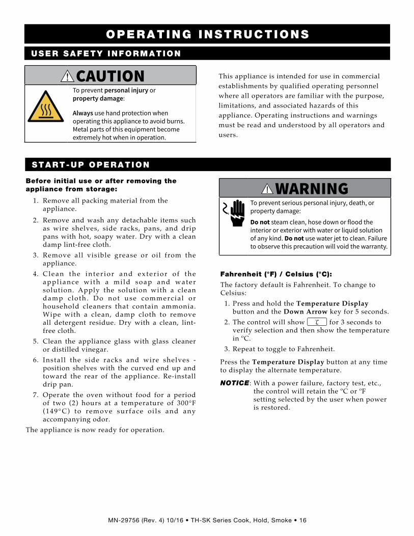
This appliance is intended for use in commercial establishments by qualified operating personnel where all operators are familiar with the purpose, limitations, and associated hazards of this appliance. Operating instructions and warnings must be read and understood by all operators and users.
START-UP OPERATION
Before initial use or after removing the appliance from storage:
1. Remove all packing material from the appliance.
2. Remove and wash any detachable items such as wire shelves, side racks, pans, and drip pans with hot, soapy water. Dry with a clean damp lint-free cloth.
3. Remove all visible grease or oil from the appliance.
4. C l e a n t h e i n t e r i o r a n d e x t e r i o r o f t h e appl iance wi th a mi ld soap and water solution. Apply the solution with a clean damp c lo th . Do not use commerc ia l or household cleaners that contain ammonia. Wipe with a clean, damp cloth to remove all detergent residue. Dry with a clean, lint-free cloth.
5. Clean the appliance glass with glass cleaner or distilled vinegar.
6. Instal l the side racks and wire shelves - position shelves with the curved end up and toward the rear of the appliance. Re-install drip pan.
7. Operate the oven without food for a period of two (2) hours at a temperature of 300°F (149°C) to remove surface o i l s and any accompanying odor.
The appliance is now ready for operation.
Fahrenheit (°F) / Celsius (°C):
The factory default is Fahrenheit. To change to Celsius: 1. Press and hold the Temperature Display
button and the Down Arrow key for 5 seconds. 2. The control will show .
C for 3 seconds to verify selection and then show the temperature in ºC.
3. Repeat to toggle to Fahrenheit.
Press the Temperature Display button at any time to display the alternate temperature.
NOTICE: With a power failure, factory test, etc., the control will retain the ºC or ºF setting selected by the user when power is restored.
CAUTIONTo prevent personal injury or property damage:
Always use hand protection when operating this appliance to avoid burns. Metal parts of this equipment become extremely hot when in operation.
W017Warning; Hot surface
WARNINGTo prevent serious personal injury, death, or property damage:
Do not steam clean, hose down or flood the interior or exterior with water or liquid solution of any kind. Do not use water jet to clean. Failure to observe this precaution will void the warranty.
Operating Instructions User Safety Information Start-up Operation

MN-29756 (Rev . 4) 10/16 • TH-SK Series Cook, Hold, Smoke • 17
OPERATING INSTRUCTIONS
I
o
I
o
Up/Down Arrow Keys
Temperature Display ButtonTime Key
Holding Indicator Light
CookingIndicator Light
On/Off Power Switch
Hold Knob Cook Knob
DigitalDisplay
Heat Indicator Light
I
o
I
o
Up/Down Arrow Keys
Temperature Display ButtonTime Key
Holding Indicator Light
CookingIndicator Light
On/Off Power Switch Hold Knob Cook Knob
DigitalDisplay
Heat Indicator Light
Smoke Timer
SmokeIndicator Light
Cook & Hold
Cook/Hold/Smoke
Cook/Hold/Smoke Instructions
MN-29756 (Rev . 4) 10/16 • TH-SK Series Cook, Hold, Smoke • 18
OPERATING INSTRUCTIONS1. Push power switch to ON (I) position.
Control will display 0°F or 0°C. 2. Set the holding temperature
- 60°F to 205°F (16°C to 96°C)• Rotate the hold knob to the desired holding
temperature. The set temperature will appear in the Digital Display 140
.F and the
Temperature Display button will illuminate. • The Holding Indicator light will illuminate
while in hold mode. 3. Set the cooking temperature
- 200°F to 325°F (94°C to 160°C)• Rotate the cook knob to the desired
temperature. The set temperature will appear in the Digital Display 250
.F and the
temperature display button will illuminate. • The Cooking Indicator light will illuminate
while in cook mode. Notice: Cooking mode not active unless timer
is running.4. Set timer.
• Press Up or Down arrows when cook knob is set to begin cooking.
• Press Up or Down arrows to adjust the time while cooking.
• Hold Timer button for 3 seconds when in cook mode to cancel timer (display shows ---- ) .
5. PREHEAT oven for 30 minutes before loading food. The Heat Indicator light will illuminate and will remain lit as long as the oven is calling for heat. When the oven temperature reaches the set temperature, the Heat Indicator light will turn off.
6. Load the oven with food and adjust cooking timer as needed.
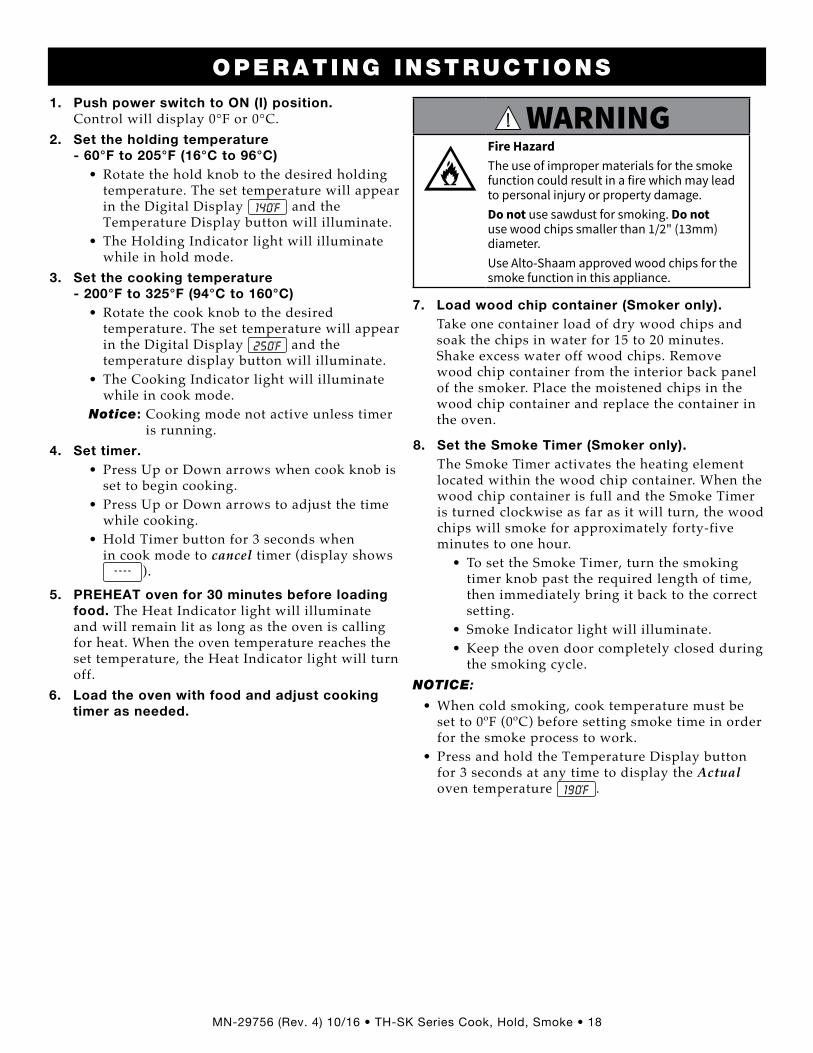
WARNINGFire HazardThe use of improper materials for the smoke function could result in a fire which may lead to personal injury or property damage. Do not use sawdust for smoking. Do not use wood chips smaller than 1/2" (13mm) diameter. Use Alto-Shaam approved wood chips for the smoke function in this appliance.
7. Load wood chip container (Smoker only). Take one container load of dry wood chips and
soak the chips in water for 15 to 20 minutes. Shake excess water off wood chips. Remove wood chip container from the interior back panel of the smoker. Place the moistened chips in the wood chip container and replace the container in the oven.
8. Set the Smoke Timer (Smoker only). The Smoke Timer activates the heating element
located within the wood chip container. When the wood chip container is full and the Smoke Timer is turned clockwise as far as it will turn, the wood chips will smoke for approximately forty-five minutes to one hour.
• To set the Smoke Timer, turn the smoking timer knob past the required length of time, then immediately bring it back to the correct setting.
• Smoke Indicator light will illuminate.• Keep the oven door completely closed during
the smoking cycle. NOTICE:
• When cold smoking, cook temperature must be set to 0ºF (0ºC) before setting smoke time in order for the smoke process to work.
• Press and hold the Temperature Display button for 3 seconds at any time to display the Actual oven temperature 190
.F .

MN-29756 (Rev . 4) 10/16 • TH-SK Series Cook, Hold, Smoke • 19
OPERATING INSTRUCTIONS
General Holding GuidelineChefs, cooks and other specialized food service personnel employ varied methods of cooking. Proper holding temperatures for a specific food product must be based on the moisture content of the product, product density, volume, and proper serving temperatures. Safe holding temperatures must also be correlated with palatability in determining the length of holding time for a specific product.
Halo Heat maintains the maximum amount of product moisture content without the addition of water, water vapor, or steam. Maintaining maximum natural product moisture preserves the natural flavor of the product and provides a more genuine taste. In addition to product moisture retention, the gentle properties of Halo Heat maintain a consistent temperature throughout the cabinet without the necessity of a heat distribution fan, thereby preventing further moisture loss due to evaporation or dehydration.
When product is removed from a high temperature cooking environment for immediate transfer into equipment with the lower temperature required for hot food holding, condensation can form on the outside of the product and on the inside of plastic containers used in self-service applications. Allowing the product to release the initial steam and heat produced by high temperature cooking can alleviate this condition. To preserve the safety and quality of freshly cooked foods, however, a maximum of 1 to 2 minutes must be the only time period allowed for the initial heat to be released from the product.
Most Halo Heat Holding Equipment is provided with a thermostat control between 60°F and 200°F (16°C to 93°C). If the unit is equipped with vents, close the vents for moist holding and open the vents for crisp holding.
Holding Temperature RangeMeat Fahrenheit Celsius
Beef Roast — Rare 130°F 54°CBeef Roast — Med/Well Done 155°F 68°CBeef Brisket 160°F–175°F 71°C–79°CCorn Beef 160°F–175°F 71°C–79°CPastrami 160°F–175°F 71°C–79°CPrime Rib — Rare 130°F 54°CSteaks — Broiled/Fried 140°F–160°F 60°C–71°CRibs — Beef Or Pork 160°F 71°CVeal 160°F–175°F 71°C–79°CHam 160°F–175°F 71°C–79°CPork 160°F–175°F 71°C–79°CLamb 160°F–175°F 71°C–79°C
PoultryChicken — Fried/Baked 160°F–175°F 71°C–79°CDuck 160°F–175°F 71°C–79°CTurkey 160°F–175°F 71°C–79°CGeneral 160°F–175°F 71°C–79°C
Fish/SeafoodFish — Baked/Fried 160°F–175°F 71°C–79°CLobster 160°F–175°F 71°C–79°CShrimp — Fried 160°F–175°F 71°C–79°C
Baked GoodsBreads/Rolls 120°F–140°F 49°C–60°C
MiscellaneousCasseroles 160°F–175°F 71°C–79°CDough — Proofing 80°F–100°F 27°C–38°CEggs — Fried 150°F–160°F 66°C–71°CFrozen Entrees 160°F–175°F 71°C–79°CHors d'oeuvres 160°F–180°F 71°C–82°CPasta 160°F–180°F 71°C–82°CPizza 160°F–180°F 71°C–82°CPotatoes 180°F 82°CPlated Meals 140°F–165°F 60°C–74°CSauces 140°F–200°F 60°C–93°CSoup 140°F–200°F 60°C–93°CVegetables 160°F–175°F 71°C–79°C
The holding temperatures listed are suggested guidelines only. All food holding should be based on internal product temperatures. Always follow local health (hygiene) regulations for all internal temperature requirements.
General Holding Guidelines

MN-29756 (Rev . 4) 10/16 • TH-SK Series Cook, Hold, Smoke • 20
CARE AND CLEANINGProtecting Stainless Steel Surfaces
It is important to guard against corrosion in the care of stainless steel
surfaces. Harsh, corrosive, or inappropriate chemicals can completely destroy the protective surface layer of stainless steel. Abrasive pads, steel wool, or metal implements
will abrade surfaces causing damage to this protective coating and will eventually result in areas of corrosion. Even water, particularly hard water that contains high to moderate concentrations of chloride, will cause oxidation and pitting that result in rust and corrosion. In addition, many acidic foods spilled and le� to remain on metal surfaces are contributing factors that will corrode surfaces.Proper cleaning agents, materials, and methods are vital to maintaining the appearance and life of this appliance. Spilled foods should be removed and the area wiped as soon as possible but at the very least, a minimum of once per day. Always thoroughly rinse surfaces a� er using a cleaning agent and wipe standing water as quickly as possible a� er rinsing.
Cleaning AgentsUse non-abrasive cleaning products designed for use on stainless steel surfaces. Cleaning agents must be chloride-free compounds and must not contain quaternary salts. Never use hydrochloric acid (muriatic acid) on stainless steel surfaces. Failure to observe this precaution will void the warranty. Always use the proper cleaning agent at the manufacturer's recommended strength. Contact your local cleaning supplier for product recommendations.
Cleaning MaterialsCleaning can usually be accomplished with the proper cleaning agent and a so� , clean cloth. When more aggressive methods are needed, use a non-abrasive scouring pad on dif� cult areas and make certain to scrub with the visible grain of surface metal to avoid surface scratches. Never use wire brushes, metal scouring pads, or scrapers to remove food residue. Failure to observe this precaution will void the warranty.
NOTICETo protect stainless steel surfaces, completely avoid the use of abrasive cleaning compounds, chloride based cleaners, or cleaners containing quaternary salts. Never use hydrochloric acid (muriatic acid) on stainless steel. Never use wire brushes, metal scouring pads or scrapers.
No
wire brushes
N
o steel pads
No scrapers
WARNINGTo prevent serious personal injury, death, or property damage:
The appliance must be cleaned thoroughly to avoid deposits of grease and or food residues inside the appliance that may catch fire. If fat deposits and/or food waste inside the appliance ignite, shut down the appliance immediately and keep the appliance door closed to extinguish the fire. If further extinguishing is required, disconnect the appliance from the main power and use a fire extinguisher (do not use water to extinguish a grease fire!). Failure to clean the appliance properly invalidates the warranty and relieves Alto-Shaam of all liability.
Care and Cleaning

MN-29756 (Rev . 4) 10/16 • TH-SK Series Cook, Hold, Smoke • 21
Clean Daily
1. Disconnect unit from power source, and let cool.
2. Remove all detachable items such as wire shelves, side racks, and drip pans. Clean these items separately.
3. Wipe the interior metal surfaces of the oven with a paper towel to remove loose food debris.
4. Clean the interior metal surfaces, door vents, and front drip tray with a damp clean cloth or sponge and any good commercial detergent.
NOTICE: Never use of abrasive cleaning compounds, chloride based cleaners, or cleaners containing quaternary salts. Never use hydrochloric acid (muriatic acid) on stainless steel.
5. Spray heavily soiled areas with a water soluble degreaser and let stand for 10 minutes, then remove soil with a plastic scouring pad.
6. Wipe control panel, door vents, door handles, and door gaskets thoroughly since these areas harbor food debris.
7. Rinse surfaces by wiping with sponge and clean warm water.
8. Remove excess water with sponge and wipe dry with a clean cloth or air dry. Leave doors open until interior is completely dry. Replace side racks and shelves.
9. Wipe door gaskets and control panel dry with a clean, soft cloth.
10. Interior can be wiped with a sanitizing solution after cleaning and rinsing. This solution must be approved for use on stainless steel food contact surfaces.
11. To help maintain the protective film coating on polished stainless steel, clean the exterior of the cabinet with a cleaner recommended for stainless steel surfaces. Spray the cleaning agent on a clean cloth and wipe with the grain of the stainless steel.
12. Clean any glass with a window cleaner.
Always follow appropriate state or local health (hygiene) regulations regarding all applicable cleaning and sanitation requirements for equipment.
Do not use oven if controls are not properly functioning
Refer to the Troubleshooting Guide located in this manual or call an authorized service technician.
CARE AND CLEANING
WARNINGTo prevent serious personal injury, death, or property damage:
Do not steam clean, hose down or flood the interior or exterior with water or liquid solution of any kind. Do not use water jet to clean. Failure to observe this precaution will void the warranty.
WARNING
To prevent serious injury, death, or property damage, always disconnect the appliance from the power source before cleaning or servicing.
Care and Cleaning Instructions

MN-29756 (Rev . 4) 10/16 • TH-SK Series Cook, Hold, Smoke • 22
Daily □ Perform daily oven cleaning as stated in this guide. □ Clean front drip tray as recommended in this guide.
Monthly □ Inspect the door gasket for signs of cracking, deformation, or damage and replace as needed. □ Inspect the door window gasket for proper seal. □ Inspect the cavity door vent slides for proper operation. □ Inspect the side racks, shelves and shelf supports for damage and replace as needed. □ Calibrate removable product probe (if applicable). □ Clean the cooling fan intake area and exhaust vents. □ Visually inspect the smoke element (if applicable). If any visual signs of deformation, cracks or breaks are seen, remove the oven from service and contact a factory authorized service technician for service.
Every 12 months (Inspection by a factory authorized technician) □ Open the control area and inspect and tighten all electrical connections. □ Inspect all electrical components. □ Inspect the smoke element and smoke element wiring (if applicable). □ Visually inspect the smoke element (if applicable). If any visual signs of deformation, cracks or breaks are seen, remove the oven from service and contact a factory authorized service technician for service.
□ Confirm proper current draw of heating elements. □ Test heating elements for electrical short to ground. Replace/repair as needed. □ Inspect the condition of the plug and cord and replace if damaged. □ Tighten the cord connection inside the appliance control area. □ Test/replace independent indicator lights (where applicable). □ Replace the control cooling fans (if applicable). □ Check the site voltage. □ Set the voltage switch (where applicable). □ Inspect and test the product probe and product probe receptacle. □ Inspect and test the control and control functions. □ Replace the control knobs. □ Visually inspect the cavity for structural integrity. □ Replace the door gasket. □ Visually inspect any door handles and hinges. Replace/repair as needed. □ Remove any loose handle and hinge screws. Apply Loctite® and then properly secure the screws. □ Inspect the perimeter bumper. Repair/replace as needed. □ Inspect the casters. Repair/replace as needed. □ Perform cavity temperature calibration per manufacturer’s recommended calibration procedures.
PREVENTATIVE MAINTENANCE CHECKLIST
Preventative Maintenance Checklist

MN-29756 (Rev . 4) 10/16 • TH-SK Series Cook, Hold, Smoke • 23
Food � avor and aroma are usually so closely related that it is dif� cult, if not impossible, to separate them. There is also an important, inseparable relationship between cleanliness and food � avor. Cleanliness, operating ef� ciency, and appearance of equipment contribute considerably to savory, appetizing foods.Most food imparts its own particular aroma and many foods also absorb existing odors. Unfortunately, during this absorption there is not a distinction between good and bad odors. The majority of objectionable � avors and odors troubling food service operations are caused by bacteria growth. Sourness, rancidity, mustiness, stale or other undesireable � avors are usually the result of germ activity.The easiest way to ensure full, natural food � avor is through comprehensive cleanliness. This means good control of both visible soil (dirt) and invisible soil (germs). A thorough approach to sanitation will provide essential cleanliness. It will ensure an attractive appearance of equipment, along with maximum ef� ciency and utility. More importantly, a good sanitation program provides one of the key elements in the prevention of food-borne illnesses.A comprehensive sanitation program should focus on the training of staff in basic sanitation procedures. This includes personal hygiene, proper handling of raw foods, cooking to a safe internal product temperature, and the routine monitoring of internal food temperatures from the time the food is received through the time the food is served.A controlled holding environment for prepared foods is just one of the important factors involved in the prevention of food-borne illnesses. Temperature monitoring and control during receiving, storage, preparation, and the service of foods are of equal importance.The most accurate method of measuring safe temperatures of both hot and cold foods is by internal product temperature. A thermometer is an effective tool for this purpose, and should be routinely used on all products that require holding at a speci� c temperature.
Internal Food Product TemperaturesHot Foods
Danger Zone 40°F to 140°F 4°C to 60°CCritical Zone 70°F to 120°F 21°C to 49°C
Safe Zone 140°F to 165°F 60°C to 74°CCold Foods
Danger Zone Above 40°F Above 4°CSafe Zone 36°F to 40°F 2°C to 4°C
Frozen FoodsDanger Zone Above 32°F Above 0°CCritical Zone 0°F to 32°F -18°C to 0°C
Safe Zone 0°F or Below -18°C or Below
Hazard Analysis (at) Critical Control Points (HACCP), is a quality control program of operating procedures to assure food integrity, quality, and safety. Taking steps necessary to augment food safety practices is both cost effective and relatively simple. Additional HACCP information is available by contacting:
Center for Food Safety and Applied NutritionFood and Drug Administration
Phone: 1-888-SAFEFOODwww.foodsafety.gov
FOOD SAFETY
Internal Food Product Temper-atures
Sanitation Food Safety

MN-29756 (Rev . 4) 10/16 • TH-SK Series Cook, Hold, Smoke • 24
SERVICE
NOTICEThis section is provided for the assistance of qualified and trained service technicians only and is not intended for use by untrained or unauthorized service personnel. Do not attempt to repair or service the oven beyond this point. Contact Alto-Shaam for the nearest authorized service agent. Repairs made by any other service agents without prior authorization by Alto-Shaam will void the warranty.
Ensure that the circuit breaker is turned “On” and your unit is receiving power before calling your Authorized Alto-Shaam Service Agent.
WARNING
To prevent serious injury, death, or property damage, always disconnect the appliance from the power source before cleaning or servicing.
DANGERTo prevent serious injury, death, or property damage, always lock-out or post breaker panel until service work has been completed.
Service

MN-29756 (Rev . 4) 10/16 • TH-SK Series Cook, Hold, Smoke • 25
TROUBLESHOOTING - ERROR CODES
SERVICE
Code Description Possible Cause s
E-10 Cavity air sensor shorted Cavity air sensor reading < 5°F (-15°C). Verify sensor integrity.See sensor test instructions below.
E-11 Cavity air sensor open Cavity air sensor reading > 517°F (269°C). Verify sensor integrity.See sensor test instructions below.
E-20Product probe is shorted
Oven will cook in time onlyProduct probe reading < 5°F (-15°C). Verify sensor integrity.See sensor test instructions below.
E-21Product probe is open
Oven will cook in time onlyProduct Probe reading > 517°F (269°C). Verify sensor integrity.See sensor test instructions below.
E-30 Under temperature Unit has been more than 25°F (14°C) below set point for longer than 90 minutes.
E-31 Over temperatureUnit has been more than 60°F (33°C) above the maximum set-point for longer than 3 minutes. Notice: Holding Cabinets with this error code are more than 145°F (81°C) above the maximum set-point.
E-32Safety switch open (Aux hi-limit switch) Contact factory.
E-38 Internal software error Contact factory.E-39 Sensor error Contact factory.E-50 Temp. measurement error Contact factory.E-51 Temp. measurement error Contact factory.E-60 Real time clock error Data set to factory default. Ensure that date and time are correct if applicable.E-61 Real time clock error Contact factory.E-64 Clock is not oscillating Contact factory.
E-70Configuration connector error (DIP switch)
Refer to wiring diagram for the particular model and ensure dip switches on the control match the settings called out on the WD. If the dip switch settings are correct according to the print replace the control.
E-78 Voltage low Voltage below 90 VAC on a 125 VAC unit, or below 190 VAC on a 208-240 VAC unit. Correct voltage.
E-79 Voltage high Voltage over 135 VAC on a 125 VAC unit, or over 250 VAC on a 208-240 VAC unit. Correct voltage.
E-80 EEPROM Error Ensure that all temperatures and times are properly set.Contact factory if problem persists.
E-81 EEPROM Error Contact factory.E-82 EEPROM Error Contact factory.E-83 EEPROM Error Contact factory.E-85 EEPROM Error All timers, if previously on, are now off. Possible bad EEPROM.
E-86 EEPROM Error Stored HACCP memory corrupted. HACCP Address reset to 1. Possible bad EEPROM. Contact factory if problem persists.
E-87 EEPROM Error Stored offsets corrupted. Offsets reset to 0. Control may need a recalibration. Possible bad EEPROM. Contact factory if problem persists.
E-88 EEPROM Error All timer set-points are reset to 1 minute. Timers, if previously on, are now off. Possible bad EEPROM.
E-90 Button stuck A button has been held down for > 60 seconds. Adjust control. Error will reset when the problem has been resolved.
E-91 Input failure Contact factory.
E-dS Datakey error Datakey digital signature incompatible. Cycle power, and install compatible Datakey if error persists.
E-dT Datakey error Datakey incompatible with control. Install compatible Datakey.E-dU Datakey unplugged Install Datakey and cycle power to control to clear error.dLto Datalogger has timed out Cycle power. Contact factory if error persists.dLSD Micro SD card not plugged in Plug in SD card and cycle power. Contact factory if error persists.
NOTICE: If in doubt, always cycle the power to the control and contact factory if the problem persists.
To test probe and air sensor:Tes t probe and air sensor by placing sensor in ice water bath and using an ohmmeter set on the ohm scale. The reading should be 100 ohms resistance. If it is more than 2 ohms higher or lower, sensor needs to be replaced.
Trouble Shooting - Error Codes

MN-29756 (Rev . 4) 10/16 • TH-SK Series Cook, Hold, Smoke • 26
SINGLE COMPARTMENT COOK & HOLD - 500-TH-II 230V sHown
SERVICE
A
2
7
9
8
35
6
1
4
27
24
28
25
26
23
15
2220
21
19
13
121411A
10
16
17
18
30
29
32
31
11B
A
33
Part numbers and drawings are subject to change without not ice .
Cook & Hold - 500, 750, 1000-TH-II Service Views
MN-29756 (Rev . 4) 10/16 • TH-SK Series Cook, Hold, Smoke • 27
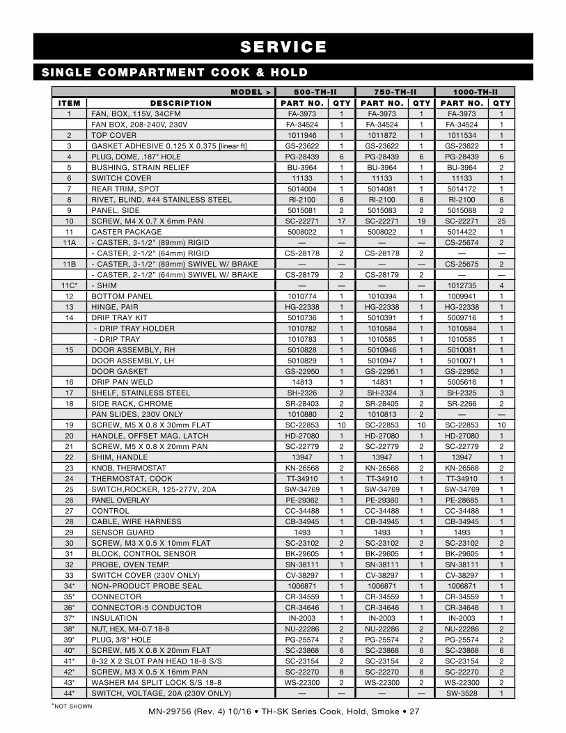
SINGLE COMPARTMENT COOK & HOLD
SERVICE
*not shown
MODEL > 500-TH-II 750-TH-II 1000-TH-II
ITEM DESCRIPTION PART NO. QTY PART NO. QTY PART NO. QTY1 FAN, BOX, 115V, 34CFM FA-3973 1 FA-3973 1 FA-3973 1
FAN BOX, 208-240V, 230V FA-34524 1 FA-34524 1 FA-34524 12 TOP COVER 1011946 1 1011872 1 1011534 13 GASKET ADHESIVE 0 .125 X 0 .375 [linear ft] GS-23622 1 GS-23622 1 GS-23622 14 PLUG, DOME, .187" HOLE PG-28439 6 PG-28439 6 PG-28439 65 BUSHING, STRAIN RELIEF BU-3964 1 BU-3964 1 BU-3964 26 SWITCH COVER 11133 1 11133 1 11133 17 REAR TRIM, SPOT 5014004 1 5014081 1 5014172 18 RIVET, BLIND, #44 STAINLESS STEEL RI-2100 6 RI-2100 6 RI-2100 69 PANEL, SIDE 5015081 2 5015083 2 5015088 210 SCREW, M4 X 0 .7 X 6mm PAN SC-22271 17 SC-22271 19 SC-22271 2511 CASTER PACKAGE 5008022 1 5008022 1 5014422 1
11A - CASTER, 3-1/2" (89mm) RIGID — — — — CS-25674 2- CASTER, 2-1/2” (64mm) RIGID CS-28178 2 CS-28178 2 — —
11B - CASTER, 3-1/2" (89mm) SWIVEL W/ BRAKE — — — — CS-25675 2- CASTER, 2-1/2” (64mm) SWIVEL W/ BRAKE CS-28179 2 CS-28179 2 — —
11C* - SHIM — — — — 1012735 412 BOTTOM PANEL 1010774 1 1010394 1 1009941 113 HINGE, PAIR HG-22338 1 HG-22338 1 HG-22338 114 DRIP TRAY KIT 5010736 1 5010391 1 5009716 1
- DRIP TRAY HOLDER 1010782 1 1010584 1 1010584 1 - DRIP TRAY 1010783 1 1010585 1 1010585 1
15 DOOR ASSEMBLY, RH 5010828 1 5010946 1 5010081 1DOOR ASSEMBLY, LH 5010829 1 5010947 1 5010071 1DOOR GASKET GS-22950 1 GS-22951 1 GS-22952 1
16 DRIP PAN WELD 14813 1 14831 1 5005616 117 SHELF, STAINLESS STEEL SH-2326 2 SH-2324 3 SH-2325 318 SIDE RACK, CHROME SR-28403 2 SR-28405 2 SR-2266 2
PAN SLIDES, 230V ONLY 1010880 2 1010813 2 — —19 SCREW, M5 X 0 .8 X 30mm FLAT SC-22853 10 SC-22853 10 SC-22853 1020 HANDLE, OFFSET MAG . LATCH HD-27080 1 HD-27080 1 HD-27080 121 SCREW, M5 X 0 .8 X 20mm PAN SC-22779 2 SC-22779 2 SC-22779 222 SHIM, HANDLE 13947 1 13947 1 13947 123 KNOB, THERMOSTAT KN-26568 2 KN-26568 2 KN-26568 224 THERMOSTAT, COOK TT-34910 1 TT-34910 1 TT-34910 125 SWITCH,ROCKER, 125-277V, 20A SW-34769 1 SW-34769 1 SW-34769 126 PANEL OVERLAY PE-29362 1 PE-29360 1 PE-28685 127 CONTROL CC-34488 1 CC-34488 1 CC-34488 128 CABLE, WIRE HARNESS CB-34945 1 CB-34945 1 CB-34945 129 SENSOR GUARD 1493 1 1493 1 1493 130 SCREW, M3 X 0 .5 X 10mm FLAT SC-23102 2 SC-23102 2 SC-23102 231 BLOCK, CONTROL SENSOR BK-29605 1 BK-29605 1 BK-29605 132 PROBE, OVEN TEMP . SN-38111 1 SN-38111 1 SN-38111 133 SWITCH COVER (230V ONLY) CV-38297 1 CV-38297 1 CV-38297 134* NON-PRODUCT PROBE SEAL 1006871 1 1006871 1 1006871 135* CONNECTOR CR-34559 1 CR-34559 1 CR-34559 136* CONNECTOR-5 CONDUCTOR CR-34646 1 CR-34646 1 CR-34646 137* INSULATION IN-2003 1 IN-2003 1 IN-2003 138* NUT, HEX, M4-0 .7 18-8 NU-22286 2 NU-22286 2 NU-22286 239* PLUG, 3/8" HOLE PG-25574 2 PG-25574 2 PG-25574 240* SCREW, M5 X 0 .8 X 20mm FLAT SC-23868 6 SC-23868 6 SC-23868 641* 8-32 X 2 SLOT PAN HEAD 18-8 S/S SC-23154 2 SC-23154 2 SC-23154 242* SCREW, M3 X 0 .5 X 16mm PAN SC-22270 8 SC-22270 8 SC-22270 243* WASHER M4 SPLIT LOCK S/S 18-8 WS-22300 2 WS-22300 2 WS-22300 244* SWITCH, VOLTAGE, 20A (230V ONLY) — — — — SW-3528 1
MN-29756 (Rev . 4) 10/16 • TH-SK Series Cook, Hold, Smoke • 28
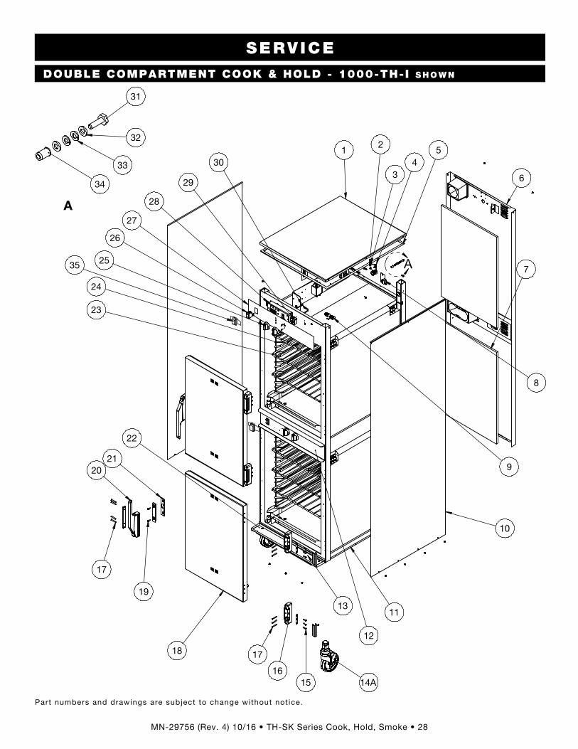
DOUBLE COMPARTMENT COOK & HOLD - 1000-TH-I sHown
SERVICE
Part numbers and drawings are subject to change without not ice .
1000-TH-I Service Views
A
6
7
1 5
10
8
28
29
27
26
25
24
23
22
11
12
1615
1718
2120
19
17
9
30
14A
43
2
A
31
32
33
34
13
35
MN-29756 (Rev . 4) 10/16 • TH-SK Series Cook, Hold, Smoke • 29
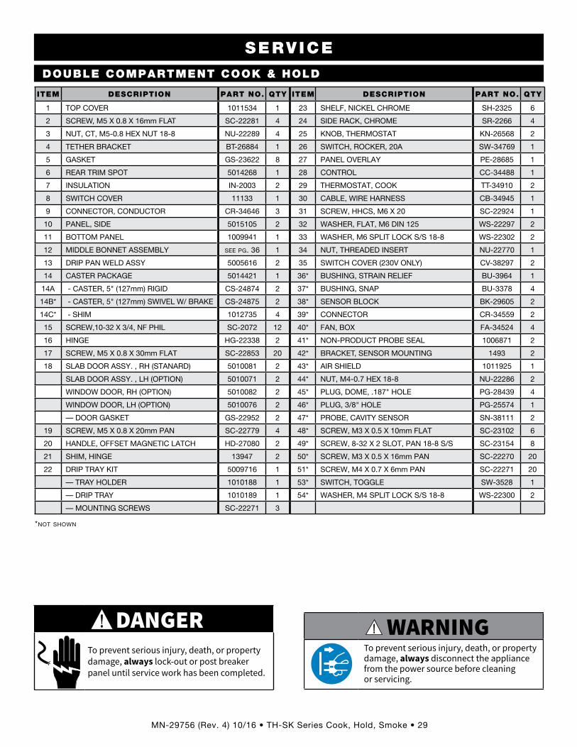
DOUBLE COMPARTMENT COOK & HOLD
SERVICE
*not shown
WARNING
To prevent serious injury, death, or property damage, always disconnect the appliance from the power source before cleaning or servicing.
DANGERTo prevent serious injury, death, or property damage, always lock-out or post breaker panel until service work has been completed.
ITEM DESCRIPTION PART NO. QTY ITEM DESCRIPTION PART NO. QTY
1 TOP COVER 1011534 1 23 SHELF, NICKEL CHROME SH-2325 6
2 SCREW, M5 X 0 .8 X 16mm FLAT SC-22281 4 24 SIDE RACK, CHROME SR-2266 4
3 NUT, CT, M5-0 .8 HEX NUT 18-8 NU-22289 4 25 KNOB, THERMOSTAT KN-26568 2
4 TETHER BRACKET BT-26884 1 26 SWITCH, ROCKER, 20A SW-34769 1
5 GASKET GS-23622 8 27 PANEL OVERLAY PE-28685 1
6 REAR TRIM SPOT 5014268 1 28 CONTROL CC-34488 1
7 INSULATION IN-2003 2 29 THERMOSTAT, COOK TT-34910 2
8 SWITCH COVER 11133 1 30 CABLE, WIRE HARNESS CB-34945 1
9 CONNECTOR, CONDUCTOR CR-34646 3 31 SCREW, HHCS, M6 X 20 SC-22924 1
10 PANEL, SIDE 5015105 2 32 WASHER, FLAT, M6 DIN 125 WS-22297 2
11 BOTTOM PANEL 1009941 1 33 WASHER, M6 SPLIT LOCK S/S 18-8 WS-22302 2
12 MIDDLE BONNET ASSEMBLY see pg. 36 1 34 NUT, THREADED INSERT NU-22770 1
13 DRIP PAN WELD ASSY 5005616 2 35 SWITCH COVER (230V ONLY) CV-38297 2
14 CASTER PACKAGE 5014421 1 36* BUSHING, STRAIN RELIEF BU-3964 1
14A - CASTER, 5" (127mm) RIGID CS-24874 2 37* BUSHING, SNAP BU-3378 4
14B* - CASTER, 5" (127mm) SWIVEL W/ BRAKE CS-24875 2 38* SENSOR BLOCK BK-29605 2
14C* - SHIM 1012735 4 39* CONNECTOR CR-34559 2
15 SCREW,10-32 X 3/4, NF PHIL SC-2072 12 40* FAN, BOX FA-34524 4
16 HINGE HG-22338 2 41* NON-PRODUCT PROBE SEAL 1006871 2
17 SCREW, M5 X 0 .8 X 30mm FLAT SC-22853 20 42* BRACKET, SENSOR MOUNTING 1493 2
18 SLAB DOOR ASSY . , RH (STANARD) 5010081 2 43* AIR SHIELD 1011925 1
SLAB DOOR ASSY . , LH (OPTION) 5010071 2 44* NUT, M4-0 .7 HEX 18-8 NU-22286 2
WINDOW DOOR, RH (OPTION) 5010082 2 45* PLUG, DOME, .187" HOLE PG-28439 4
WINDOW DOOR, LH (OPTION) 5010076 2 46* PLUG, 3/8" HOLE PG-25574 1
— DOOR GASKET GS-22952 2 47* PROBE, CAVITY SENSOR SN-38111 2
19 SCREW, M5 X 0 .8 X 20mm PAN SC-22779 4 48* SCREW, M3 X 0 .5 X 10mm FLAT SC-23102 6
20 HANDLE, OFFSET MAGNETIC LATCH HD-27080 2 49* SCREW, 8-32 X 2 SLOT, PAN 18-8 S/S SC-23154 8
21 SHIM, HINGE 13947 2 50* SCREW, M3 X 0 .5 X 16mm PAN SC-22270 20
22 DRIP TRAY KIT 5009716 1 51* SCREW, M4 X 0 .7 X 6mm PAN SC-22271 20
— TRAY HOLDER 1010188 1 53* SWITCH, TOGGLE SW-3528 1
— DRIP TRAY 1010189 1 54* WASHER, M4 SPLIT LOCK S/S 18-8 WS-22300 2
— MOUNTING SCREWS SC-22271 3

MN-29756 (Rev . 4) 10/16 • TH-SK Series Cook, Hold, Smoke • 30
Part numbers and drawings are subject to change without not ice .
SERVICE
5
4
7
6
3
2
1
8
10
9
11
1000-TH-II, 230V only
12
COOK & HOLD ELECTRONIC COMPONENTS
ITEM DESCRIPTION PART NO. QTY
1 STAR LOCK WASHER WS-2467 1
2 SCREW, 10-32 X 1/4" PAN HD GROUND SC-2190 1
3 BUSHING, 3/8" BLACK HOLE BU-3419 1
4 CONNECTOR, #16 FERRULE - 230V CR-34828 3
CONNECTOR, #12 FERRULE - 120V CR-34830 3
5 CORDSET 120V CD-3397 1
230V (CEE 7/7) CD-3922 1
230V (CH2-16P) CD-36321 1
230V (BS1363) CD-33925 1
230V (AS/NZS 3112) CD-38149 1
6 SCREW, 6-32 X 1 1/4" ROUND HD SC-2365 2
7 T-BLOCK BK-3019 1
8 LINE FILTER, 115/250V 50/60HZ - 230V ONLY FI-33225 1
9 1/2" HOLE BUSHING BU-3006 1
10 SCREW, M4 X 0 .7 X 6mm PAN SC-22271 2
11 AIR SHIELD SPOT WELD ASSB 500 5013997 1
750, 1000 5014097 1
12 SWITCH, VOLTAGE, 20A (1000-TH-II, 230V ONLY) SW-3528 1
Electronic Components View & Parts

MN-29756 (Rev . 4) 10/16 • TH-SK Series Cook, Hold, Smoke • 31
SERVICE
A
7
6
1
5
12A
9
24
23
1011
1514
16
18
A
36
35
34
332
3 4
12B
22
8
13
17
2119
20
19
B
38
37
40
39
B
27
25
26
28
29
30
3132
41
Part numbers and drawings are subject to change without not ice .
WARNING
To prevent serious injury, death, or property damage, always disconnect the appliance from the power source before cleaning or servicing.
DANGERTo prevent serious injury, death, or property damage, always lock-out or post breaker panel until service work has been completed.
SINGLE COMPARTMENT COOK/HOLD/SMOKE - 1000-sK/I I sHown
Cook, Hold, Smoke - 767-SK, 1000-SK/II Service Views

MN-29756 (Rev. 4) 10/16 • TH-SK Series Cook, Hold, Smoke • 32*not shown
SERVICEMODELS 767-SK 1000-SK/II
ITEM DESCRIPTION PART NO. QTY PART NO. QTY1 TOP COVER 1011872 1 1011534 12 GASKETS, ADHESIVE, .125 X .375 [linear ft] GS-23622 1 GS-23622 13 PLUG, HOLE 3/8" PG-25574 1 PG-25574 14 PLUG, DOME, 187" HOLE PG-28439 6 PG-28439 65 BUSHING, STRAIN RELIEF BU-3964 1 BU-3964 16 SWITCH COVER 11133 1 11133 17 INSULATION IN-2003 1 IN-2003 18 REAR TRIM, SPOT 5014137 1 5014204 19 PANEL, SIDE 5015083 2 5015088 2
10 BOTTOM PANEL 1010394 1 1009941 111 DRIP TRAY KIT 5010391 1 5009716 1
- DRIP TRAY 1010584 1 1010189 1- DRIP TRAY BRACKET 1010585 1 1010188 1
12 CASTER PACKAGE 5014422 1 5014422 112A - CASTER, 3-1/2” (89mm) RIGID CS-25674 2 CS-25674 212B - CASTER, 3-1/2” (89mm) SWIVEL WITH BRAKE CS-25675 2 CS-25675 212C* - SHIM 1012735 4 1012735 413 HINGE COVER CV-22171 2 CV-22171 214 SCREW, M5 X 0.8 X 20mm FLAT SC-23868 6 SC-23868 615 HINGE, 1-3/8" OFFSET, PAIR, CHROME HG-22338 2 HG-22338 216 SCREW, M5 X 0.8 X 30mm FLAT SC-22853 6 SC-22853 617 DRIP PAN WELD 14831 1 5005616 118 DOOR ASSEMBLY, RH (STANDARD) 5013154 1 5013154 1
DOOR ASSEMBLY, LH (OPTION) 5013155 1 5013155 1DOOR GASKET GS-22952 1 GS-22952 1
19 HANDLE, OFFSET MAGNETIC LATCH HD-27080 1 HD-27080 120 SCREW, M5 X 0.8 X 20mm PAN SC-22779 2 SC-22779 221 SHIM, HANDLE 13947 1 13947 122 SHELF, STAINLESS STEEL SH-2324 2 SH-2325 223 SHELF, RIB RACK SH-2743 1 SH-29474 124 SIDE RACKS SR-28405 2 SR-2266 2* PAN SLIDES 1010813 — — —
25 KNOB KN-26568 3 KN-26568 326 SWITCH, ROCKER, 20A SW-34769 1 SW-34769 127 PANEL OVERLAY PE-29361 1 PE-29383 128 CONTROL CC-34488 1 CC-34488 129 THERMOSTAT, COOK TT-34910 1 TT-34910 130 TIMER, 1 HR, 208-240V TR-34539 1 TR-34539 1
TIMER, 1 HR, 120V TR-34540 1 TR-34540 131 CABLE HARNESS CB-34945 1 CB-34945 132 CONNECTOR-5 CONDUCTOR CR-34646 2 CR-34646 233 NUT, THREADED INSERT, M6, 230V ONLY NU-22770 1 NU-22770 134 WASHER, M6 SPLIT LOCK S/S 18-8, 230V ONLY WS-22302 2 WS-22302 235 WASHER, FLAT, M6, DIN 125, 230V ONLY WS-22297 2 WS-22297 236 SCREW, HHCS, M6 X 20, 230V ONLY SC-22924 1 SC-22924 137 SENSOR GUARD 1493 1 1493 138 SCREW, M3 X 0.5 X 10mm FLAT SC-23102 2 SC-23102 239 BLOCK, CONTROL SENSOR BK-29605 1 BK-29605 140 PROBE, OVEN TEMP SN-38111 1 SN-38111 141 SWITCH COVER (230V ONLY) CV-38297 1 CV-38297 142* NON-PRODUCT PROBE SEAL 1006871 1 1006871 143* SMOKE ELEMENT, 208-240V, 230V EL-35022 1 EL-35022 1
SMOKE ELEMENT, 120V EL-35023 1 EL-35023 144* ELEMENT COVER, SMOKE 1010409 1 1011813 145* CHIP TRAY WELD 4652R 1 4652R 146* BRACKET, CHIP TRAY BT-29217 1 BT-29217 147* SMOKE HEATER PLATE WELD 5003782 1 5003782 148* BLOCK, SENSOR BK-29605 1 BK-29605 149* BLOCK, TERMINAL, PORCELAIN BK-33546 1 BK-33546 150* BUSHING, BLACK, 5/8" SNAP BU-3611 2 BU-3611 251* SENSOR, OVEN TEMPERATURE SN-38111 1 SN-38111 152* FAN, BOX, 120V FA-3973 1 FA-3973 1
FAN BOX, 208-240V, 230V FA-34524 1 FA-34524 153* PILOT LIGHT, 208-240V LI-3951 1 LI-3951 1
PILOT LIGHT, 120V LI-3027 1 LI-3027 154* SWITCH, TOGGLE, VOLTAGE SW-3528 1 SW-3528 155* SENSOR, OVEN TEMPERATURE SN-38111 1 SN-38111 1
MN-29756 (Rev . 4) 10/16 • TH-SK Series Cook, Hold, Smoke • 33
A
8
9
1 5
13
11
32
33
31
30
29
27
28
25
15
16
1817
19
2423
22
19
12
35
14B
6
4
3
10
7
2
37
36
26
20
2114A
A
38
39
40
41
34
42
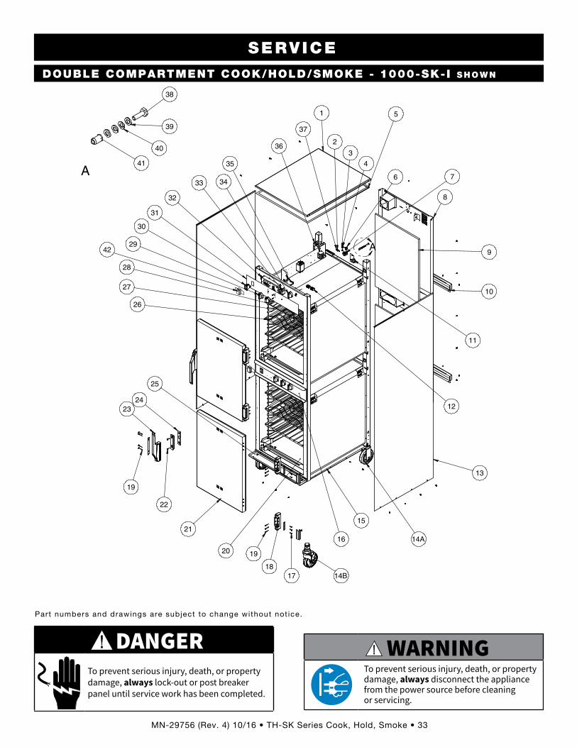
Part numbers and drawings are subject to change without not ice .
WARNING
To prevent serious injury, death, or property damage, always disconnect the appliance from the power source before cleaning or servicing.
DANGERTo prevent serious injury, death, or property damage, always lock-out or post breaker panel until service work has been completed.
SERVICE
DOUBLE COMPARTMENT COOK/HOLD/SMOKE - 1000-sK-I sHown
1000-SK-I Service Views
MN-29756 (Rev . 4) 10/16 • TH-SK Series Cook, Hold, Smoke • 34*not shown
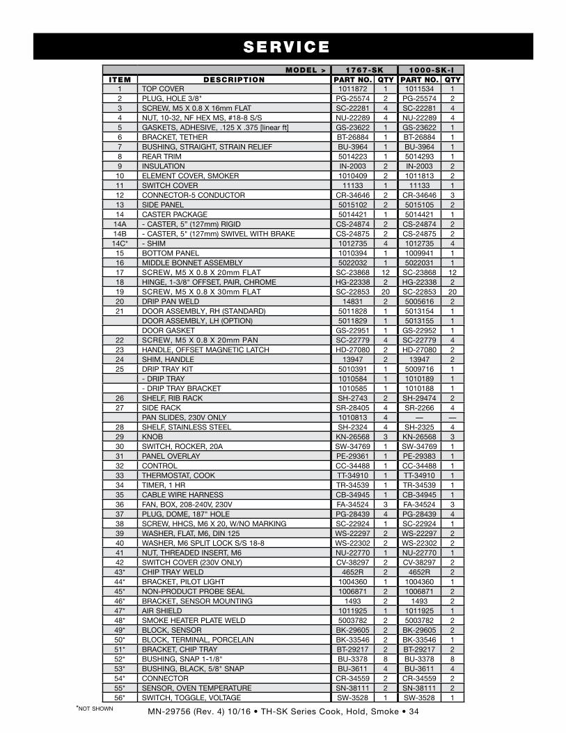
SERVICEMODEL > 1767-SK 1000-SK-I
ITEM DESCRIPTION PART NO. QTY PART NO. QTY1 TOP COVER 1011872 1 1011534 12 PLUG, HOLE 3/8" PG-25574 2 PG-25574 23 SCREW, M5 X 0 .8 X 16mm FLAT SC-22281 4 SC-22281 44 NUT, 10-32, NF HEX MS, #18-8 S/S NU-22289 4 NU-22289 45 GASKETS, ADHESIVE, .125 X .375 [linear ft] GS-23622 1 GS-23622 16 BRACKET, TETHER BT-26884 1 BT-26884 17 BUSHING, STRAIGHT, STRAIN RELIEF BU-3964 1 BU-3964 18 REAR TRIM 5014223 1 5014293 19 INSULATION IN-2003 2 IN-2003 210 ELEMENT COVER, SMOKER 1010409 2 1011813 211 SWITCH COVER 11133 1 11133 112 CONNECTOR-5 CONDUCTOR CR-34646 2 CR-34646 313 SIDE PANEL 5015102 2 5015105 214 CASTER PACKAGE 5014421 1 5014421 1
14A - CASTER, 5” (127mm) RIGID CS-24874 2 CS-24874 214B - CASTER, 5" (127mm) SWIVEL WITH BRAKE CS-24875 2 CS-24875 214C* - SHIM 1012735 4 1012735 415 BOTTOM PANEL 1010394 1 1009941 116 MIDDLE BONNET ASSEMBLY 5022032 1 5022031 117 SCREW, M5 X 0 .8 X 20mm FLAT SC-23868 12 SC-23868 1218 HINGE, 1-3/8" OFFSET, PAIR, CHROME HG-22338 2 HG-22338 219 SCREW, M5 X 0 .8 X 30mm FLAT SC-22853 20 SC-22853 2020 DRIP PAN WELD 14831 2 5005616 221 DOOR ASSEMBLY, RH (STANDARD) 5011828 1 5013154 1
DOOR ASSEMBLY, LH (OPTION) 5011829 1 5013155 1DOOR GASKET GS-22951 1 GS-22952 1
22 SCREW, M5 X 0 .8 X 20mm PAN SC-22779 4 SC-22779 423 HANDLE, OFFSET MAGNETIC LATCH HD-27080 2 HD-27080 224 SHIM, HANDLE 13947 2 13947 225 DRIP TRAY KIT 5010391 1 5009716 1
- DRIP TRAY 1010584 1 1010189 1- DRIP TRAY BRACKET 1010585 1 1010188 1
26 SHELF, RIB RACK SH-2743 2 SH-29474 227 SIDE RACK SR-28405 4 SR-2266 4
PAN SLIDES, 230V ONLY 1010813 4 — —28 SHELF, STAINLESS STEEL SH-2324 4 SH-2325 429 KNOB KN-26568 3 KN-26568 330 SWITCH, ROCKER, 20A SW-34769 1 SW-34769 131 PANEL OVERLAY PE-29361 1 PE-29383 132 CONTROL CC-34488 1 CC-34488 133 THERMOSTAT, COOK TT-34910 1 TT-34910 134 TIMER, 1 HR TR-34539 1 TR-34539 135 CABLE WIRE HARNESS CB-34945 1 CB-34945 136 FAN, BOX, 208-240V, 230V FA-34524 3 FA-34524 337 PLUG, DOME, 187" HOLE PG-28439 4 PG-28439 438 SCREW, HHCS, M6 X 20, W/NO MARKING SC-22924 1 SC-22924 139 WASHER, FLAT, M6, DIN 125 WS-22297 2 WS-22297 240 WASHER, M6 SPLIT LOCK S/S 18-8 WS-22302 2 WS-22302 241 NUT, THREADED INSERT, M6 NU-22770 1 NU-22770 142 SWITCH COVER (230V ONLY) CV-38297 2 CV-38297 243* CHIP TRAY WELD 4652R 2 4652R 244* BRACKET, PILOT LIGHT 1004360 1 1004360 145* NON-PRODUCT PROBE SEAL 1006871 2 1006871 246* BRACKET, SENSOR MOUNTING 1493 2 1493 247* AIR SHIELD 1011925 1 1011925 148* SMOKE HEATER PLATE WELD 5003782 2 5003782 249* BLOCK, SENSOR BK-29605 2 BK-29605 250* BLOCK, TERMINAL, PORCELAIN BK-33546 2 BK-33546 151* BRACKET, CHIP TRAY BT-29217 2 BT-29217 252* BUSHING, SNAP 1-1/8" BU-3378 8 BU-3378 853* BUSHING, BLACK, 5/8" SNAP BU-3611 4 BU-3611 454* CONNECTOR CR-34559 2 CR-34559 255* SENSOR, OVEN TEMPERATURE SN-38111 2 SN-38111 256* SWITCH, TOGGLE, VOLTAGE SW-3528 1 SW-3528 1

MN-29756 (Rev. 4) 10/16 • TH-SK Series Cook, Hold, Smoke • 35
6
5
7
8
4
213
13
910
11
12
Part numbers and drawings are subject to change without not ice.
ITEM DESCRIPTION PART NO. QTY ITEM DESCRIPTION PART NO. QTY1 STAR LOCK WASHER WS-2467 1 8 SCREW, 6-32 X 1-1/4" ROUND HD SC-2365 22 GROUND SCREW SC-2190 1 9 CONNECTOR, FERRULE #18 CR-34827 2**3 ELECTRIC CHASSIS 5014097 1 10 ELEMENT, SMOKE 208-240V, 230V EL-35022 1**4 BUSHING, 3/8" BLACK HOLE BU-3419 1 120V EL-35023 1**5 CONNECTOR, FERRULE #12 CR-34830 3 11 CONNECTOR, QUICK DISCONNECT CR-34638 26 CORDSET 120V (NEMA 5-20) CD-3397 1 12 PILOT LIGHT 208-240V, 230V LI-3951 1
230V (CEE 7/7) CD-3922 1 120V LI-3027 1 230V (CH2-16P) CD-36321 1 13 BUSHING, 1/2" HOLE BU-3006 1 230V (BS1363) CD-33925 1 14* LINE FILTER (230V ONLY) FI-33225 1 230V (AS/NZS 3112) CD-38149 1 15* SCREW, M4 X 0.7 X 6mm PAN SC-22271 2
7 T-BLOCK BK-3019 1
WARNING
To prevent serious injury, death, or property damage, always disconnect the appliance from the power source before cleaning or servicing.
DANGERTo prevent serious injury, death, or property damage, always lock-out or post breaker panel until service work has been completed.
*not shown **quantity per compartment
SERVICE
COOK/HOLD/SMOKE ELECTRONIC COMPONENTS
Electrical Components

MN-29756 (Rev. 4) 10/16 • TH-SK Series Cook, Hold, Smoke • 36
CABLE HEATING KITS
WARNING
To prevent serious injury, death, or property damage, always disconnect the appliance from the power source before cleaning or servicing.
DANGERTo prevent serious injury, death, or property damage, always lock-out or post breaker panel until service work has been completed.
CABLE HEATING KIT >(ONE KIT REQUIRED PER CAVITY)
#4879500, 750, 1000, 767 - 120V 500, 750 - 120V, 208-240V
#48811000, 767, 1767 - 208-240V
ALL 230V
ITEM DESCRIPTION QTY QTY
CB-3045 CABLE HEATING ELEMENT 95 FT. 210 FT.
CR-3226 RING CONNECTOR 6 12
IN-3488 INSULATION CORNER 1 FT. 1 FT.
BU-3105 SHOULDER BUSHING 6 12
BU-3106 CUP BUSHING 6 12
ST-2439 STUD 6 12
NU-2215 HEX NUT 12 24
SL-3063 INSULATING SLEEVE 6 12
TA-3540 ELECTRICAL TAPE 1 ROLL 1 ROLL
SERVICE
MID-BONNET CONTROL PANEL - 1767-SK shown
5
1 2
34
8
9
10
7
6
11
16
15
13
12
14
Part numbers and drawings are subject to change without not ice.
ITEM DESCRIPTION PART NO. QTY ITEM DESCRIPTION PART NO. QTY
1 CONTROL CC-34488 1 9 BRACKET, PILOT LIGHT MTG 1004360 1
2 NUT, M4-0.7 HEX 18-8 NU-2296 2 10 PILOT LIGHT, WHITE, 250V LI-3951 1
3 WASHER, M4 SPLIT LOCK S/S 18-8 WS-22300 2 11 CONNECTOR-5 CONDUCTOR CR-34646 2
4 CONNECTOR CR-34826 2 12 SCREW, M3 X 0.5 X 16mm PAN SC-22270 2
5 CABLE, WIRE HARNESS CB-34945 1 13 KNOB, T-STAT CONTROL KN-26568 3
6 THERMOSTAT,COOK TT-34910 1 14 SWITCH COVER (230V ONLY) CV-38297 1
7 TIMER, 1HR, 120V TR-34540 1 15 SWITCH, ROCKER, 125-277V, 20A SW-34769 1
8 NUT, HEX #8-32 NU-2296 2 16 PANEL OVERLAY PE-29441 1

MN-29756 (Rev . 4) 10/16 • TH-SK Series Cook, Hold, Smoke • 37
Wire Diagrams Always refer to the wire diagram(s) included with the unit for most current version.

MN-29756 (Rev . 4) 10/16 • TH-SK Series Cook, Hold, Smoke • 38

MN-29756 (Rev . 4) 10/16 • TH-SK Series Cook, Hold, Smoke • 39

MN-29756 (Rev . 4) 10/16 • TH-SK Series Cook, Hold, Smoke • 40
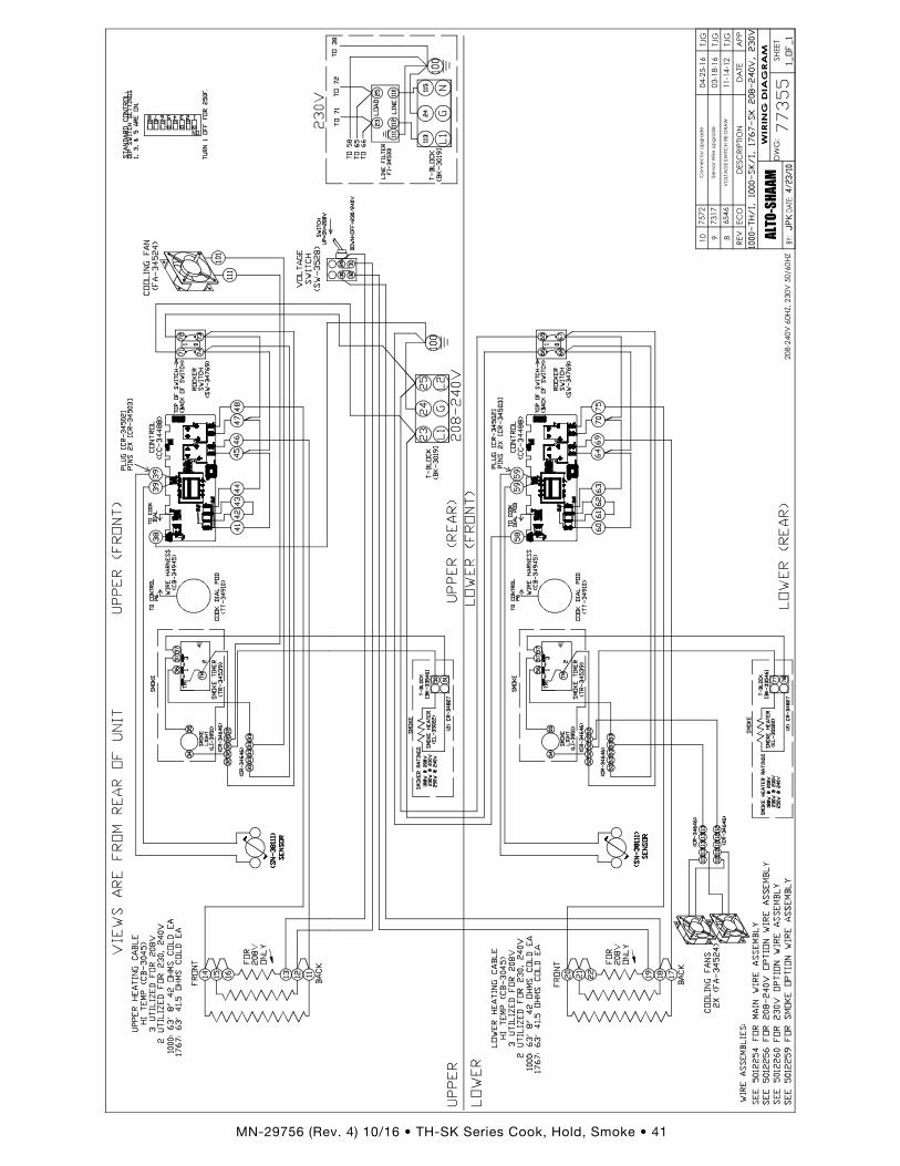
MN-29756 (Rev . 4) 10/16 • TH-SK Series Cook, Hold, Smoke • 41

TRANSPORTATION DAMAGE and CLAIMSAll Alto-Shaam equipment is sold F.O.B. shipping point, and when accepted by the carrier, such shipments become the property of the consignee.Should damage occur in shipment, do not put the appliance into service until the damage has been inspected by an authorized Alto-Shaam service provider.Should damage occur in shipment, do not put the appliance into service until the damage has been inspected by an authorized Alto-Shaam service provider.
Shipping damages are a matter between the carrier and the consignee. In such cases, the carrier is assumed to be responsible for the safe delivery of the merchandise, unless negligence can be established on the part of the shipper.
1. Make an immediate inspection while the equipment is still in the truck or immediately after it is moved to the receiving area. Do not wait until after the material is moved to a storage area.
2. Do not sign a delivery receipt or a freight bill until you have made a proper count and inspection of all merchandise received.3. Note all damage to packages directly on the carrier’s delivery receipt.4. Make certain the driver signs this receipt. If he refuses to sign, make a notation of this refusal on the receipt.5. If the driver refuses to allow inspection, write the following on the delivery receipt:
Driver refuses to allow inspection of containers for visible damage.6. Telephone the carrier’s office immediately upon finding damage, and request an inspection. Mail a written confirmation of the
time, date, and the person called.7. Save any packages and packing material for further inspection by the carrier.8. Promptly file a written claim with the carrier and attach copies of all supporting paperwork.
We will continue our policy of assisting our customers in collecting claims which have been properly filed and actively pursued. We cannot, however, file any damage claims for you, assume the responsibility of any claims, or accept deductions in payment for such claims.
LIMITED WARRANTYAlto-Shaam, Inc. warrants to the original purchaser only that any original part that is found to be defective in material or workmanship will, at Alto-Shaam's option, subject to provisions hereinafter stated, be replaced with a new or rebuilt part.The original parts warranty period is as follows: For the refrigeration compressor on Alto-Shaam Quickchillers™, five (5) years from the date of installation of appliance. For the heating element on Halo Heat® cooking and holding ovens, as long as the original purchaser owns the oven. This
excludes holding only equipment. For all other original parts, one (1) year from the date of installation of appliance or fifteen (15) months from the shipping date, whichever
occurs first. The labor warranty period is one (1) year from the date of installation or fifteen (15) months from the shipping date, whichever occurs first. Alto-Shaam will bear normal labor charges performed during standard business hours, excluding overtime, holiday rates or any
additional fees. To be valid, a warranty claim must be asserted during the applicable warranty period. This warranty is not transferable.THIS WARRANTY DOES NOT APPLY TO:
1. Calibration.2. Replacement of light bulbs, door gaskets, and/or the replacement of glass due to damage of any kind.3. Equipment damage caused by accident, shipping, improper installation or alteration.4. Equipment used under conditions of abuse, misuse, carelessness or abnormal conditions, including but not limited to, equipment
subjected to harsh or inappropriate chemicals, including but not limited to, compounds containing chloride or quaternary salts, poor water quality, or equipment with missing or altered serial numbers.
5. Damage incurred as a direct result of poor water quality, inadequate maintenance of steam generators and/or surfaces affected by water quality. Water quality and required maintenance of steam generating equipment is the responsibility of the owner/operator.
6. Damage caused by use of any cleaning agent other than Alto-Shaam's Combitherm® Cleaner, including but not limited to damage due to chlorine or other harmful chemicals. Use of Alto-Shaam's Combitherm® Cleaner on Combitherm® ovens is highly recommended.
7. Any losses or damage resulting from malfunction, including loss of product, food product, revenue, or consequential or incidental damages of any kind.
8. Equipment modified in any manner from original model, substitution of parts other than factory authorized parts, removal of any parts including legs, or addition of any parts.
This warranty is exclusive and is in lieu of all other warranties, express or implied, including the implied warranties of merchantability and fitness for a particular purpose. In no event shall Alto-Shaam be liable for loss of use, loss of revenue or profit, or loss of product, or for any indirect, special, incidental, or consequential damages. No person except an officer of Alto-Shaam, Inc. is authorized to modify this warranty or to incur on behalf of Alto-Shaam any other obligation or liability in connection with Alto-Shaam equipment.
P R I N T E D I N U . S .A .
Effective November 1, 2012
W164 N9221 Water Street • P.O. Box 450Menomonee Falls, Wisconsin 53052-0450 U.S.A.
PHONE: 262.251.3800 • 800.558.8744 U.S.A. / CANADAFAX: 262.251.7067 • 800.329.8744 U.S.A. ONLY
www.alto-shaam.com
Warranty Transportation Damage and Claims
Limited Warranty