Embed Size (px)
Citation preview
Model-based DevelopmentTool Chain at Volvo Cars
Products
MotionDesk VisualizesSimulations in 3-D
Business
Interview with thePresident of dSPACE Inc.
1/2002
FACTS . PROJECTS . EVENTSNEWSdSPACE
dSPACENEWS
1/2002
2
Editorial3 by Dr. Herbert Hanselmann,
President and CEO
Customers4 Model-based Development
Tool Chain at Volvo Cars6 C Code Reaches New Heights at
Nord-Micro8 Renault: Validation of Powertrain
ECUs10 Opel Vectra Heading for its
World Premiere12 The Relativity Mission at Stanford
University14 Paderborn University: Magnetic
Wave Moves Railway Shuttle
Products15 3-D Animation with MotionDesk15 MicroAutoBox Now at 300 MHz16 Calibration System Under Way16 Catalog 2002 and Demo CD
CONTENTS
10
Business17 Kevin Kott President of dSPACE Inc.17 User Conference in the USA18 Trip to Japan18 German User Conference19 Info and Dates
dSPACE NEWSdSPACE NEWS is published periodically by:
dSPACE GmbH . Technologiepark . 25 D-33100 PaderbornTel.: +49 5251 1 63 80 . Fax: +49 5251 6 65 [email protected] . [email protected]
Editor: Bettina HenkingLayout: Beate Eckert, Ute Bergmann
dSPACE Contributors:Robert Bevington, Günther Gruhn, Louise Hackett,Herbert Hanselmann, Susanne Köhl, Thomas Pöhlmann,Gerhard Reiß, Christine Smith
© Copyright 2002All rights reserved. Reproduction of all or parts of thispublication is permitted provided the source is stated.
Products and brand names are trademarks or registeredtrademarks of their respective holders.
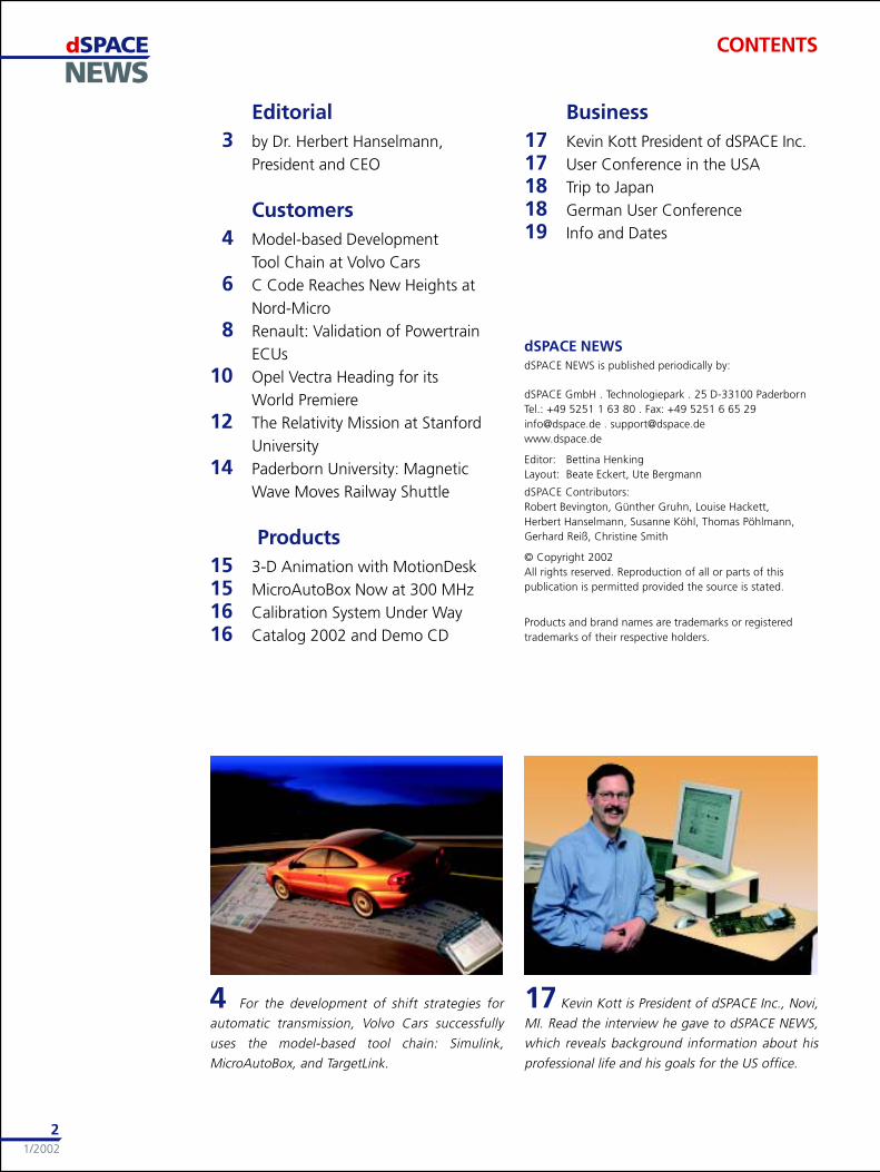
17 Kevin Kott is President of dSPACE Inc., Novi,
MI. Read the interview he gave to dSPACE NEWS,
which reveals background information about his
professional life and his goals for the US office.
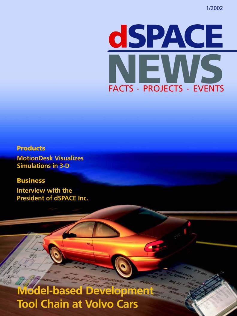
4 For the development of shift strategies for
automatic transmission, Volvo Cars successfully
uses the model-based tool chain: Simulink,
MicroAutoBox, and TargetLink.
dSPACENEWS
1/2002
3
15 Visualizing the dynamic behavior of vehicles
during hardware-in-the-loop simulation is per-
formed by MotionDesk, the new 3-D online anima-
tion tool.
16 In cooperation with automotive customers,
dSPACE Calibration System is currently being devel-
oped. This powerful tool will help you perform all
calibration and measuring tasks on ECUs.
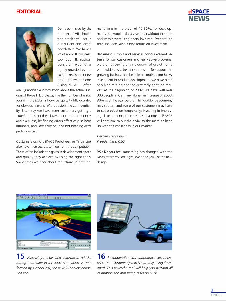
EDITORIAL
Don’t be misled by the
number of HIL simula-
tion articles you see in
our current and recent
newsletters. We have a
lot of non-HIL business,
too. But HIL applica-
tions are maybe not as
tightly guarded by our
customers as their new
product developments
(using dSPACE) often
are. Quantifiable information about the actual suc-
cess of those HIL projects, like the number of errors
found in the ECUs, is however quite tightly guarded
for obvious reasons. Without violating confidential-
ity, I can say we have seen customers getting a
100% return on their investment in three months
and even less, by finding errors effectively, in large
numbers, and very early on, and not needing extra
prototype cars.
Customers using dSPACE Prototyper or TargetLink
also have their secrets to hide from the competition.
These often include the gains in development speed
and quality they achieve by using the right tools.
Sometimes we hear about reductions in develop-
ment time in the order of 40-50%, for develop-
ments that would take a year or so without the tools
and with several engineers involved. Preparation
time included. Also a nice return on investment.
Because our tools and services bring excellent re-
turns for our customers and really solve problems,
we are not seeing any slowdown of growth on a
worldwide basis. Just the opposite. To support the
growing business and be able to continue our heavy
investment in product development, we have hired
at a high rate despite the extremely tight job mar-
ket. At the beginning of 2002, we have well over
300 people in Germany alone, an increase of about
30% over the year before. The worldwide economy
may sputter, and some of our customers may have
to cut production temporarily: investing in improv-
ing development processes is still a must. dSPACE
will continue to put the pedal-to-the-metal to keep
up with the challenges in our market.
Herbert Hanselmann
President and CEO
P.S.: Do you feel something has changed with the
Newsletter? You are right. We hope you like the new
design.
dSPACENEWS
1/2002
4
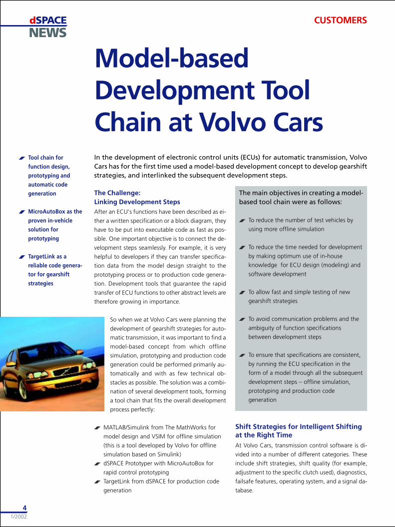
Model-basedDevelopment ToolChain at Volvo CarsIn the development of electronic control units (ECUs) for automatic transmission, VolvoCars has for the first time used a model-based development concept to develop gearshiftstrategies, and interlinked the subsequent development steps.
The Challenge:Linking Development StepsAfter an ECU’s functions have been described as ei-
ther a written specification or a block diagram, they
have to be put into executable code as fast as pos-
sible. One important objective is to connect the de-
velopment steps seamlessly. For example, it is very
helpful to developers if they can transfer specifica-
tion data from the model design straight to the
prototyping process or to production code genera-
tion. Development tools that guarantee the rapid
transfer of ECU functions to other abstract levels are
therefore growing in importance.
So when we at Volvo Cars were planning the
development of gearshift strategies for auto-
matic transmission, it was important to find a
model-based concept from which offline
simulation, prototyping and production code
generation could be performed primarily au-
tomatically and with as few technical ob-
stacles as possible. The solution was a combi-
nation of several development tools, forming
a tool chain that fits the overall development
process perfectly:
MATLAB/Simulink from The MathWorks for
model design and VSIM for offline simulation
(this is a tool developed by Volvo for offline
simulation based on Simulink)
dSPACE Prototyper with MicroAutoBox for
rapid control prototyping
TargetLink from dSPACE for production code
generation
The main objectives in creating a model-based tool chain were as follows:
To reduce the number of test vehicles by
using more offline simulation
To reduce the time needed for development
by making optimum use of in-house
knowledge for ECU design (modeling) and
software development
To allow fast and simple testing of new
gearshift strategies
To avoid communication problems and the
ambiguity of function specifications
between development steps
To ensure that specifications are consistent,
by running the ECU specification in the
form of a model through all the subsequent
development steps – offline simulation,
prototyping and production code
generation
Shift Strategies for Intelligent Shiftingat the Right TimeAt Volvo Cars, transmission control software is di-
vided into a number of different categories. These
include shift strategies, shift quality (for example,
adjustment to the specific clutch used), diagnostics,
failsafe features, operating system, and a signal da-
tabase.
Tool chain for
function design,
prototyping and
automatic code
generation
MicroAutoBox as the
proven in-vehicle
solution for
prototyping
TargetLink as a
reliable code genera-
tor for gearshift
strategies
CUSTOMERS
dSPACENEWS
1/2002
5
The new model-based development process will ini-
tially cover the development of shift strategies only.
These involve functions that ”decide” when the
transmission should perform a gearshift. Such func-
tions could include:
Cruise control: Gearshifts during constant
speed driving
Geartronic: Manual shifting with the
automatic transmission gearbox
Winter: Prevents wheelslip in slippery
conditions
HOT (Hot Oil Temperature): Prevents hardware
damage due to overheating
Quickstep: Detects ’sporty’ driving and adjusts
shift points to support this
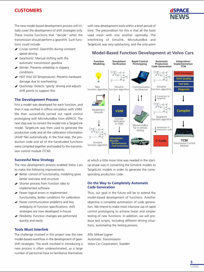
The Development ProcessFirst a model was developed for each function, and
then it was verified in offline simulation with VSIM.
We then successfully carried out rapid control
prototyping with MicroAutoBox from dSPACE. The
next step was to convert the model into a TargetLink
model. TargetLink was then used to generate the
production code and all the calibration information
(ASAP file) automatically. In the final step, the pro-
duction code and all of the handcoded functions
were compiled together and loaded to the transmis-
sion control module (TCM).
Successful New StrategyThe new development process enabled Volvo Cars
to make the following improvements:
Better control of functionality; modeling gives
better overview and structure
Shorter process from function idea to
implemented software
Fewer logical errors in implemented
functionality, better conditions for calibration
Fewer communication problems and less
ambiguity of function specifications; shift
strategies are now developed in-house
Flexibility: Function changes are performed
quickly and easily
Tools Must InterlinkThe challenge involved in this project was the new
model-based workflow in the development of gear-
shift strategies. The work involved in introducing a
new process is often underestimated, as a large
number of personnel have to familiarize themselves
with new development tools within a brief period of
time. The precondition for this is that all the tools
used mesh with one another optimally. The
interlinking of Simulink, MicroAutoBox and
TargetLink was very satisfactory, and the only point
at which a little more time was needed in the start-
up phase was in converting the Simulink models to
TargetLink models in order to generate the corre-
sponding production code.
On the Way to Completely AutomaticCode Generation
Thus, our goal in the future will be to extend the
model-based development of functions. Another
objective is complete automation of code genera-
tion. We intend to make more intensive use of rapid
control prototyping to achieve faster and simpler
testing of new functions. In addition, we will pro-
duce test scripts, including different driving situa-
tions, automating the testing process.
MSc Mikael Lygner
Automatic Transmissions
Volvo Car Corporation, Sweden
CUSTOMERS
dSPACENEWS
1/2002
6
CUSTOMERS
C Code Reaches NewHeights at Nord-Micro
Code generation
twice as fast with
TargetLink
Easy code verification
Reliable C code
production for
airborne systems
Nord-Micro develops and manufactures cabin pressure control systems (CPCS) for aircraftmanufacturers worldwide. This system includes software that has to meet the highest re-quirements regarding safety and comfort. With TargetLink, the dSPACE production codegeneration software, Nord-Micro successfully generated C code for all demanding con-trol tasks. From releasing the software requirements to the first running prototype, theteam needed only 9 months in comparison to 18 months for former projects that wereconducted without TargetLink.
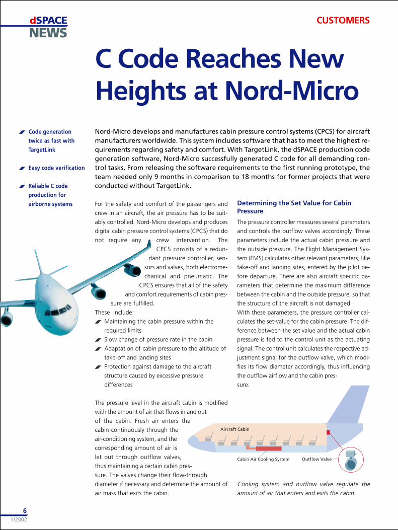
Cooling system and outflow valve regulate the
amount of air that enters and exits the cabin.
For the safety and comfort of the passengers and
crew in an aircraft, the air pressure has to be suit-
ably controlled. Nord-Micro develops and produces
digital cabin pressure control systems (CPCS) that do
not require any crew intervention. The
CPCS consists of a redun-
dant pressure controller, sen-
sors and valves, both electrome-
chanical and pneumatic. The
CPCS ensures that all of the safety
and comfort requirements of cabin pres-
sure are fulfilled.
These include:
Maintaining the cabin pressure within the
required limits
Slow change of pressure rate in the cabin
Adaptation of cabin pressure to the altitude of
take-off and landing sites
Protection against damage to the aircraft
structure caused by excessive pressure
differences
The pressure level in the aircraft cabin is modified
with the amount of air that flows in and out
of the cabin. Fresh air enters the
cabin continuously through the
air-conditioning system, and the
corresponding amount of air is
let out through outflow valves,
thus maintaining a certain cabin pres-
sure. The valves change their flow-through
diameter if necessary and determine the amount of
air mass that exits the cabin.
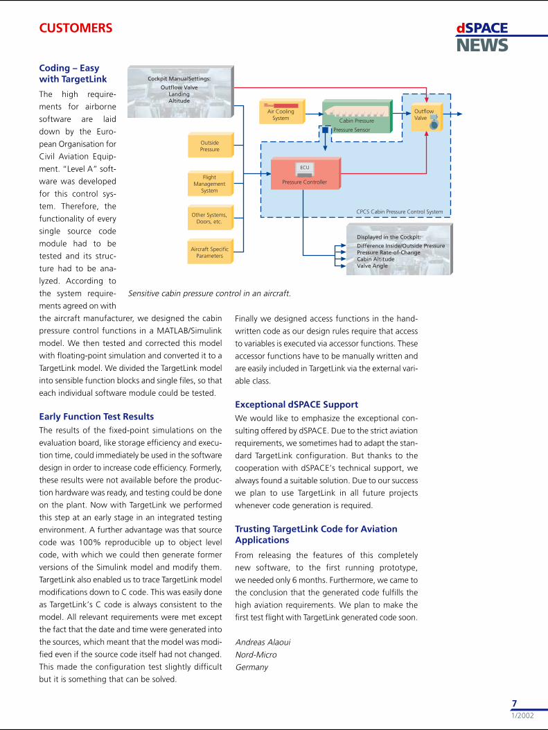
Determining the Set Value for CabinPressure
The pressure controller measures several parameters
and controls the outflow valves accordingly. These
parameters include the actual cabin pressure and
the outside pressure. The Flight Management Sys-
tem (FMS) calculates other relevant parameters, like
take-off and landing sites, entered by the pilot be-
fore departure. There are also aircraft specific pa-
rameters that determine the maximum difference
between the cabin and the outside pressure, so that
the structure of the aircraft is not damaged.
With these parameters, the pressure controller cal-
culates the set-value for the cabin pressure. The dif-
ference between the set value and the actual cabin
pressure is fed to the control unit as the actuating
signal. The control unit calculates the respective ad-
justment signal for the outflow valve, which modi-
fies its flow diameter accordingly, thus influencing
the outflow airflow and the cabin pres-
sure.
dSPACENEWS
1/2002
7
CUSTOMERS
Sensitive cabin pressure control in an aircraft.
Coding – Easywith TargetLink
The high require-
ments for airborne
software are laid
down by the Euro-
pean Organisation for
Civil Aviation Equip-
ment. “Level A” soft-
ware was developed
for this control sys-
tem. Therefore, the
functionality of every
single source code
module had to be
tested and its struc-
ture had to be ana-
lyzed. According to
the system require-
ments agreed on with
the aircraft manufacturer, we designed the cabin
pressure control functions in a MATLAB/Simulink
model. We then tested and corrected this model
with floating-point simulation and converted it to a
TargetLink model. We divided the TargetLink model
into sensible function blocks and single files, so that
each individual software module could be tested.
Early Function Test ResultsThe results of the fixed-point simulations on the
evaluation board, like storage efficiency and execu-
tion time, could immediately be used in the software
design in order to increase code efficiency. Formerly,
these results were not available before the produc-
tion hardware was ready, and testing could be done
on the plant. Now with TargetLink we performed
this step at an early stage in an integrated testing
environment. A further advantage was that source
code was 100% reproducible up to object level
code, with which we could then generate former
versions of the Simulink model and modify them.
TargetLink also enabled us to trace TargetLink model
modifications down to C code. This was easily done
as TargetLink’s C code is always consistent to the
model. All relevant requirements were met except
the fact that the date and time were generated into
the sources, which meant that the model was modi-
fied even if the source code itself had not changed.
This made the configuration test slightly difficult
but it is something that can be solved.
Finally we designed access functions in the hand-
written code as our design rules require that access
to variables is executed via accessor functions. These
accessor functions have to be manually written and
are easily included in TargetLink via the external vari-
able class.
Exceptional dSPACE SupportWe would like to emphasize the exceptional con-
sulting offered by dSPACE. Due to the strict aviation
requirements, we sometimes had to adapt the stan-
dard TargetLink configuration. But thanks to the
cooperation with dSPACE’s technical support, we
always found a suitable solution. Due to our success
we plan to use TargetLink in all future projects
whenever code generation is required.
Trusting TargetLink Code for AviationApplications
From releasing the features of this completely
new software, to the first running prototype,
we needed only 6 months. Furthermore, we came to
the conclusion that the generated code fulfills the
high aviation requirements. We plan to make the
first test flight with TargetLink generated code soon.
Andreas Alaoui
Nord-Micro
Germany
dSPACENEWS
1/2002
8
The increasing complexity of embedded software for electronic control units (ECUs) meansthat Renault needs a convenient and flexible environment for system testing. Since thecompany employs ECUs from different suppliers, the decision to switch to the indepen-dent system partner dSPACE was an easy one. The first turn-key Simulator was deliveredto Renault in early 2001. The good results achieved with this, together with positive ex-periences with the flexible dSPACE concept in other projects, prompted Renault to acquireadditional dSPACE Simulators shortly afterwards.
reduce delays in software validation and at the same
time enlarge the test range.
ECU Development at RenaultRenault gives its engine ECU suppliers not only the
written software specifications, but also some con-
troller strategies and functions. These are produced
by Renault’s development teams using specification
tools such as MATLAB/Simulink/StateFlow from The
MathWorks.
The ECU suppliers then implement the controller
functions.
By the time Renault receives the first prototype of an
ECU, the hardware has already been tested in open-
loop tests.
dSPACE SimulatorIn spring 2001, a turn-key dSPACE Simulator Full-
Size was delivered to Renault. This had been
adapted to the company’s needs and was ready to
use in all kinds of applications.
The Simulator’s modular hardware architecture is
based on a PowerPC processor board. There are
components for realistic sensor signal simulation,
simulation of electric faults and signal conditioning.
This modularity will enable Renault to add other
components later on, and even to test networked
ECUs. An ASAM-MCD 3MC interface allows the re-
mote control of external calibration tools.
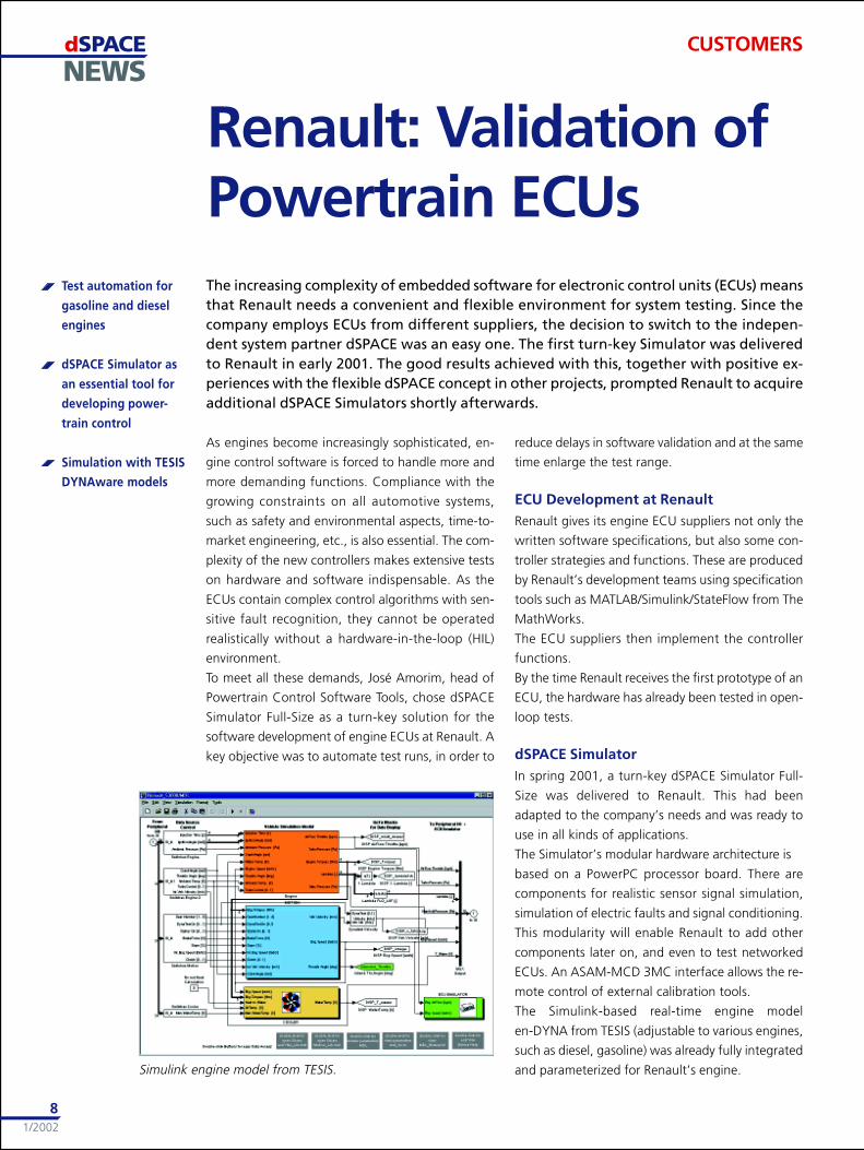
The Simulink-based real-time engine model
en-DYNA from TESIS (adjustable to various engines,
such as diesel, gasoline) was already fully integrated
and parameterized for Renault’s engine.
As engines become increasingly sophisticated, en-
gine control software is forced to handle more and
more demanding functions. Compliance with the
growing constraints on all automotive systems,
such as safety and environmental aspects, time-to-
market engineering, etc., is also essential. The com-
plexity of the new controllers makes extensive tests
on hardware and software indispensable. As the
ECUs contain complex control algorithms with sen-
sitive fault recognition, they cannot be operated
realistically without a hardware-in-the-loop (HIL)
environment.
To meet all these demands, José Amorim, head of
Powertrain Control Software Tools, chose dSPACE
Simulator Full-Size as a turn-key solution for the
software development of engine ECUs at Renault. A
key objective was to automate test runs, in order to
Renault: Validation ofPowertrain ECUs
Simulink engine model from TESIS.
Test automation for
gasoline and diesel
engines
dSPACE Simulator as
an essential tool for
developing power-
train control
Simulation with TESIS
DYNAware models
CUSTOMERS
dSPACENEWS
1/2002
9
ControlDesk is used to change parameters and
monitor the test results during real-time simulation.
Here, initial layouts were also provided. As Renault
wanted to start by using dSPACE Simulator as a plat-
form for software validation, the enhanced
ControlDesk Test Automation options were very use-
ful. With the test algorithms prepared by dSPACE
as a reference, it was easy for Renault to develop
further test sequences step-by-step, and set up an
extensive test database.
Function Development at RenaultWith en-DYNA, each engine model can be modified
to simulate a different engine (VVT, turbocharger,
etc.). This allows Renault to test newly implemented
functions on the ECU before the real engine actu-
ally exists. Once the functions have been sufficiently
validated on the Simulator, they are passed to
Renault’s supplier for implementation.
On the other hand, if an engine is already physically
available at Renault, its ECU functionality also under-
goes thorough testing with the HIL system before fi-
nal tests are run on a test bench, followed by test
drives.
The two approaches significantly reduce test and
validation runs on real-engine test benches, and
even more importantly: They allow wider test ranges
with no risk.
ECU Software Validation –Status Quo
dSPACE Simulator’s first task at Renault is software
validation. The team has already developed a series
of engine-specific tests and run them as lights-out
tests overnight and on weekends. Several common
and specific test series had been produced in an im-
pressively short time. This made it possible to find
and understand hardware-related bugs that had
previously been impossible to locate even for the
supplier. Renault’s choice of such a comprehensive
hardware-in-the-loop Simulator had proved to be a
good one.
During test drives (test bench or road), external data
measured by the ECU is collected by a calibration
tool and can be reproduced in the lab with the help
of ControlDesk’s Test Automation Library (TALib).
The advantage lies in repeatability and in the ability
to run large numbers of tests with different param-
eter settings.
Renault’s Further PlansJosé Amorim’s team will continue setting up a de-
tailed test database covering all imaginable sce-
narios. Renault has already employed standard
Rapid Control Prototyping systems (MicroAutoBox,
modular dSPACE Prototyper systems) to develop and
prototype new control functions for existing en-
gines. Now the dSPACE Simulator will be used to de-
velop new strategies for new engines and new con-
trollers. Renault has already acquired more Simula-
tors and intends to make intensive use of them in
the management of complex gasoline and diesel en-
gines, such as common rail.
They plan to perform on-board diagnostics (OBD)
tests, plus functionality and RAMS (Reliability Avail-
ability Maintainability Safety) tests. Suppliers will
also be expected to eliminate hardware and soft-
ware problems at an early stage using comprehen-
sive HIL Simulators. Moreover, Renault plans to
simulate new engines and test prototyping ECUs
with dSPACE Simulator even before the specifica-
tions go to its manufacturers, and is also about to
test networked ECUs (such as gearboxes, ABS, ESP).
HIL is an essential element in Renault’s strategy for
developing powertrain control systems.
Contact:
José Amorim, [email protected],
François Seprey, [email protected],
Powertrain Control Software Tools
France
CUSTOMERS
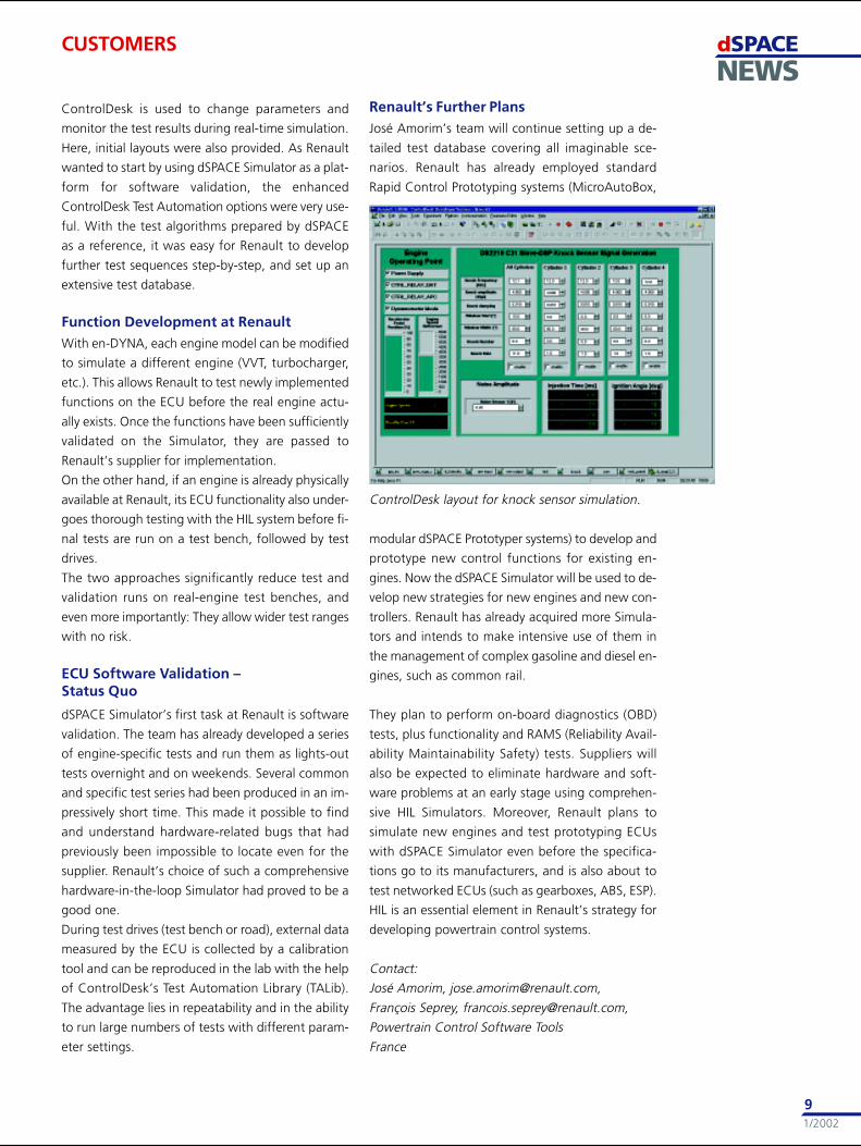
ControlDesk layout for knock sensor simulation.
dSPACENEWS
1/2002
10
dSPACE Simulator
for testing car
interior electronics
15 networked
ECUs
Extensive CAN bus
and I/O require-
ments
CUSTOMERS
Opel Vectra Headingfor its World PremiereIn January, the new Opel Vectra went into production in one of the world’s most modernautomobile plants in Rüsselsheim, Germany. Equipped with a variety of new features, thenew model will have its world premiere at the Geneva Motor Show in March. The Vectrawill feature a completely new, driver-oriented design with pioneering technology for ahigh level of safety and comfort. Thanks to positive experience made with former dSPACEsystems, Opel decided to rely on dSPACE Simulator for running the hardware-in-the-looptests on the Vectra’s new electronics systems.
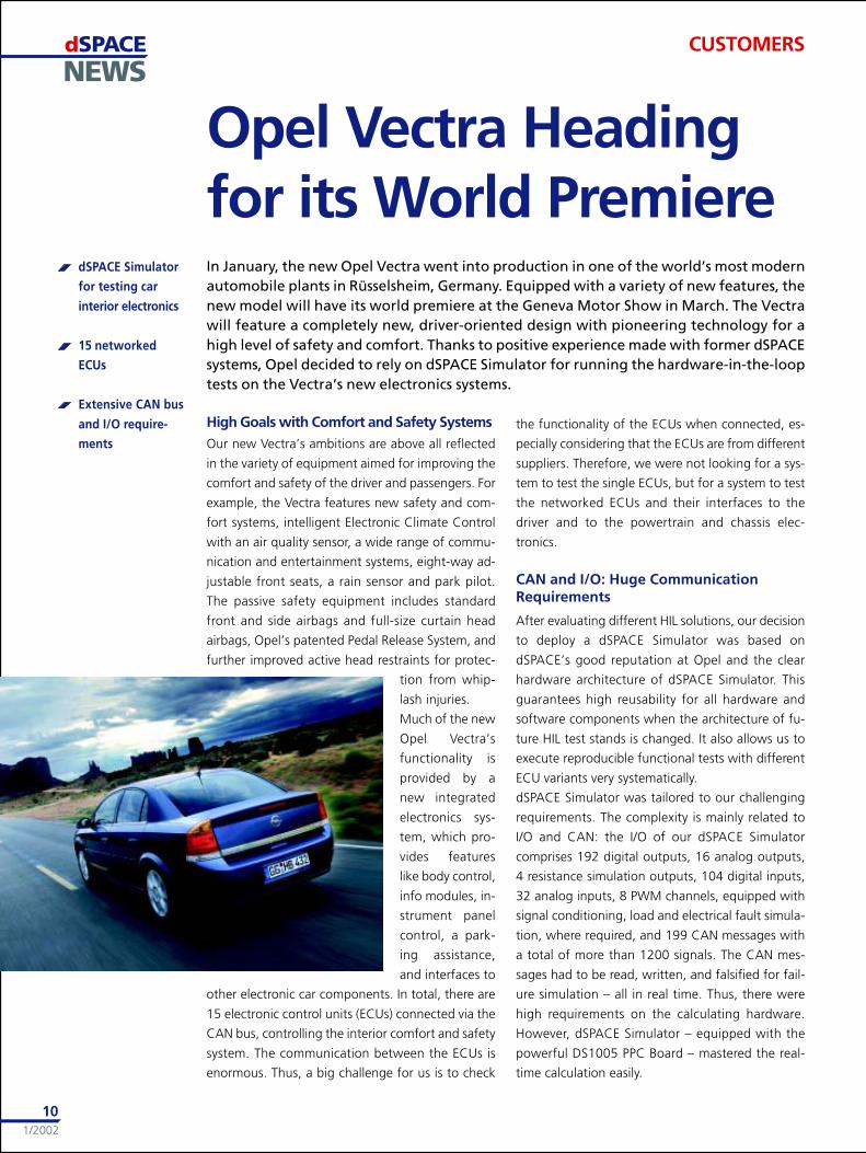
High Goals with Comfort and Safety SystemsOur new Vectra’s ambitions are above all reflected
in the variety of equipment aimed for improving the
comfort and safety of the driver and passengers. For
example, the Vectra features new safety and com-
fort systems, intelligent Electronic Climate Control
with an air quality sensor, a wide range of commu-
nication and entertainment systems, eight-way ad-
justable front seats, a rain sensor and park pilot.
The passive safety equipment includes standard
front and side airbags and full-size curtain head
airbags, Opel’s patented Pedal Release System, and
further improved active head restraints for protec-
tion from whip-
lash injuries.
Much of the new
Opel Vectra’s
functionality is
provided by a
new integrated
electronics sys-
tem, which pro-
vides features
like body control,
info modules, in-
strument panel
control, a park-
ing assistance,
and interfaces to
other electronic car components. In total, there are
15 electronic control units (ECUs) connected via the
CAN bus, controlling the interior comfort and safety
system. The communication between the ECUs is
enormous. Thus, a big challenge for us is to check
the functionality of the ECUs when connected, es-
pecially considering that the ECUs are from different
suppliers. Therefore, we were not looking for a sys-
tem to test the single ECUs, but for a system to test
the networked ECUs and their interfaces to the
driver and to the powertrain and chassis elec-
tronics.
CAN and I/O: Huge CommunicationRequirements
After evaluating different HIL solutions, our decision
to deploy a dSPACE Simulator was based on
dSPACE’s good reputation at Opel and the clear
hardware architecture of dSPACE Simulator. This
guarantees high reusability for all hardware and
software components when the architecture of fu-
ture HIL test stands is changed. It also allows us to
execute reproducible functional tests with different
ECU variants very systematically.
dSPACE Simulator was tailored to our challenging
requirements. The complexity is mainly related to
I/O and CAN: the I/O of our dSPACE Simulator
comprises 192 digital outputs, 16 analog outputs,
4 resistance simulation outputs, 104 digital inputs,
32 analog inputs, 8 PWM channels, equipped with
signal conditioning, load and electrical fault simula-
tion, where required, and 199 CAN messages with
a total of more than 1200 signals. The CAN mes-
sages had to be read, written, and falsified for fail-
ure simulation – all in real time. Thus, there were
high requirements on the calculating hardware.
However, dSPACE Simulator – equipped with the
powerful DS1005 PPC Board – mastered the real-
time calculation easily.
dSPACENEWS
1/2002
11
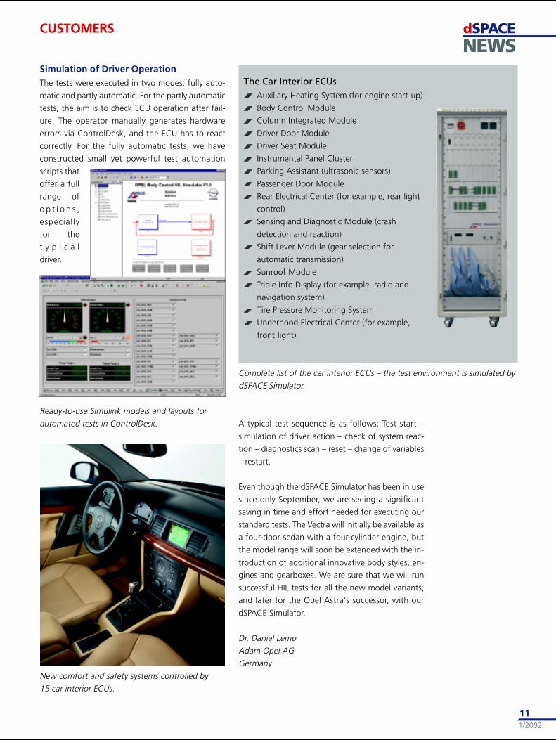
The Car Interior ECUsAuxiliary Heating System (for engine start-up)
Body Control Module
Column Integrated Module
Driver Door Module
Driver Seat Module
Instrumental Panel Cluster
Parking Assistant (ultrasonic sensors)
Passenger Door Module
Rear Electrical Center (for example, rear light
control)
Sensing and Diagnostic Module (crash
detection and reaction)
Shift Lever Module (gear selection for
automatic transmission)
Sunroof Module
Triple Info Display (for example, radio and
navigation system)
Tire Pressure Monitoring System
Underhood Electrical Center (for example,
front light)
CUSTOMERS
Simulation of Driver OperationThe tests were executed in two modes: fully auto-
matic and partly automatic. For the partly automatic
tests, the aim is to check ECU operation after fail-
ure. The operator manually generates hardware
errors via ControlDesk, and the ECU has to react
correctly. For the fully automatic tests, we have
constructed small yet powerful test automation
scripts that
offer a full
range of
o p t i o n s ,
especially
for the
t y p i c a l
driver.
A typical test sequence is as follows: Test start –
simulation of driver action – check of system reac-
tion – diagnostics scan – reset – change of variables
– restart.
Even though the dSPACE Simulator has been in use
since only September, we are seeing a significant
saving in time and effort needed for executing our
standard tests. The Vectra will initially be available as
a four-door sedan with a four-cylinder engine, but
the model range will soon be extended with the in-
troduction of additional innovative body styles, en-
gines and gearboxes. We are sure that we will run
successful HIL tests for all the new model variants,
and later for the Opel Astra’s successor, with our
dSPACE Simulator.
Dr. Daniel Lemp
Adam Opel AG
Germany
Ready-to-use Simulink models and layouts for
automated tests in ControlDesk.
New comfort and safety systems controlled by
15 car interior ECUs.
Complete list of the car interior ECUs – the test environment is simulated by
dSPACE Simulator.
dSPACENEWS
1/2002
12
American scientists calculated that according to
Einstein’s theory about space-time curvature, a ro-
tating massive body should slowly drag space and
time around with it – an effect called frame drag-
ging. This force was supposed to push a gyroscope’s
axis out of alignment as it orbits the Earth. Gravity
Probe B (GP-B) will use four gyroscopes to prove this
prediction and measure the frame-dragging effect
to a precision of 1% or better. It will also measure
the geodetic effect, a result of the warping of space-
time, with an accuracy of 0.01%.
The Physics of GyroscopesGyroscopes are not only common traditional toys,
today they are used as high-tech gyroscopes in gy-
rocompasses, like in advanced navigation systems
on the Space Shuttle. There is one feature that
makes them so interesting for that purpose: Fast ro-
tating gyroscopes tend to keep a stable spin axis. If
a force acts perpendicular to the rotation axis, the
gyroscope’s angular momentum (generated by its
own perpendicular movement) presents a strong
counterforce.
Axis Movement by a Hair’s WidthGP-B will place the incredibly precise gyroscopes in
polar Earth orbit at 400 miles. Each gyroscope spin
axis will be aligned with the inertial axis of the ro-
tating satellite. The satellite and its four gyroscopes
will point toward a distant star, which will be used
as the inertial reference. During the year, General
Relativity predicts that the gyroscopes will turn in
two directions. The geodetic effect will tend to push
the gyro axes in a direction perpendicular to the
The Relativity Missionat Stanford UniversityWhile Albert Einstein’s theory of General Relativity has been around for nearly a century,tests confirming its ideas are few and far from conclusive. Gravity Probe B is an experi-ment developed by NASA and Stanford University that will measure how space and timeare influenced by the presence of Earth. dSPACE enables a hardware-in-the-loop set-upto test the highly sensitive electronic system of the most stringent and precise test of gen-eral relativity ever done.
frame-dragging effect, which allow it to be mea-
sured separately. GP-B will keep the telescope con-
tinuously pointed at the original guide star. After a
year, Einstein’s General Theory predicts that the axis
of the gyroscope will have moved six arcseconds due
to the curvature of space-time and 42 milliarc-sec-
onds (the width of a human hair, seen from a quar-
ter mile away) due to the frame-dragging
effect.
The Gyroscope Suspension SystemThe gyroscope quartz rotors are the roundest ob-
jects ever machined. They are each about the size of
a ping-pong ball and will spin at about 10,000 rpm.
We have a Gyroscope Suspension System (GSS) that
electrostatically suspends the spherical gyroscope.
The GSS
s u s p e n d s
the rotor by
measur ing
the capaci-
tance be-
tween the
rotor sur-
face and
3 pairs of
electrodes,
and if the
rotor is cen-
tered, the rotor/electrode capacitance of a pair will
be equal. If not, the GSS capacitance bridge will out-
put an error voltage. This voltage (and the voltage
of the other 2 bridges) will be used to determine
the necessary correction voltages needed to force
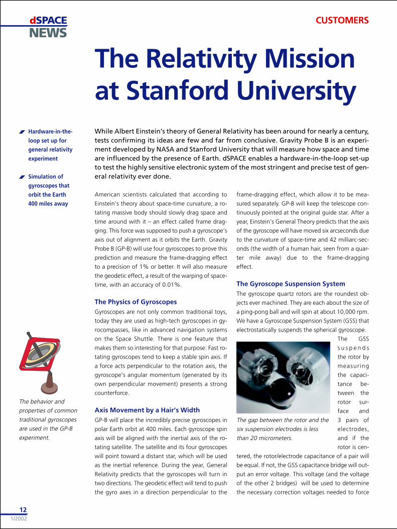
The behavior and
properties of common
traditional gyroscopes
are used in the GP-B
experiment.
CUSTOMERS
Hardware-in-the-
loop set up for
general relativity
experiment
Simulation of
gyroscopes that
orbit the Earth
400 miles away
The gap between the rotor and the
six suspension electrodes is less
than 20 micrometers.
dSPACENEWS
1/2002
13
������������
�������� ��� ���������� ��� �������� ���
�� ����� ���������
��� �������
���������
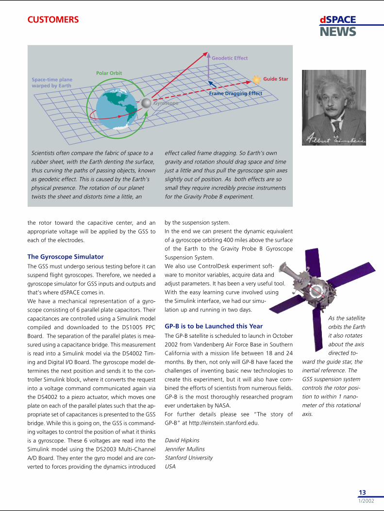
Scientists often compare the fabric of space to a
rubber sheet, with the Earth denting the surface,
thus curving the paths of passing objects, known
as geodetic effect. This is caused by the Earth’s
physical presence. The rotation of our planet
twists the sheet and distorts time a little, an
As the satellite
orbits the Earth
it also rotates
about the axis
directed to-
ward the guide star, the
inertial reference. The
GSS suspension system
controls the rotor posi-
tion to within 1 nano-
meter of this rotational
axis.
CUSTOMERS
effect called frame dragging. So Earth’s own
gravity and rotation should drag space and time
just a little and thus pull the gyroscope spin axes
slightly out of position. As both effects are so
small they require incredibly precise instruments
for the Gravity Probe B experiment.
the rotor toward the capacitive center, and an
appropriate voltage will be applied by the GSS to
each of the electrodes.
The Gyroscope SimulatorThe GSS must undergo serious testing before it can
suspend flight gyroscopes. Therefore, we needed a
gyroscope simulator for GSS inputs and outputs and
that’s where dSPACE comes in.
We have a mechanical representation of a gyro-
scope consisting of 6 parallel plate capacitors. Their
capacitances are controlled using a Simulink model
compiled and downloaded to the DS1005 PPC
Board. The separation of the parallel plates is mea-
sured using a capacitance bridge. This measurement
is read into a Simulink model via the DS4002 Tim-
ing and Digital I/O Board. The gyroscope model de-
termines the next position and sends it to the con-
troller Simulink block, where it converts the request
into a voltage command communicated again via
the DS4002 to a piezo actuator, which moves one
plate on each of the parallel plates such that the ap-
propriate set of capacitances is presented to the GSS
bridge. While this is going on, the GSS is command-
ing voltages to control the position of what it thinks
is a gyroscope. These 6 voltages are read into the
Simulink model using the DS2003 Multi-Channel
A/D Board. They enter the gyro model and are con-
verted to forces providing the dynamics introduced
by the suspension system.
In the end we can present the dynamic equivalent
of a gyroscope orbiting 400 miles above the surface
of the Earth to the Gravity Probe B Gyroscope
Suspension System.
We also use ControlDesk experiment soft-
ware to monitor variables, acquire data and
adjust parameters. It has been a very useful tool.
With the easy learning curve involved using
the Simulink interface, we had our simu-
lation up and running in two days.
GP-B is to be Launched this YearThe GP-B satellite is scheduled to launch in October
2002 from Vandenberg Air Force Base in Southern
California with a mission life between 18 and 24
months. By then, not only will GP-B have faced the
challenges of inventing basic new technologies to
create this experiment, but it will also have com-
bined the efforts of scientists from numerous fields.
GP-B is the most thoroughly researched program
ever undertaken by NASA.
For further details please see “The story of
GP-B” at http://einstein.stanford.edu.
David Hipkins
Jennifer Mullins
Stanford University
USA
dSPACENEWS
1/2002
14
CUSTOMERS
The new railway system is based on magnetic drive
technology, providing contact-free power transmis-
sion with a frictionless, lightweight drive and low
maintenance costs. Another feature is also impres-
sive: Small autonomous shuttles will take passengers
and loads to their destinations without having to
change trains.
Precise Control RequirementsThe drive module is based on a doubly-fed linear
motor, which is divided into two parts: The primary
(stator) is placed between the tracks and the sec-
ondary is placed in each individual shuttle. The drive
control is realized on board the shuttle via second-
ary currents. Only the stator segment that the
shuttle is approaching is supplied with primary cur-
rent. And the stator has to be controlled according
to the commands given by the shuttle drive control.
The electrical position of the stator current therefore
has to be controlled with great accuracy, as the syn-
chronous transition from one stator segment to the
other is very important for a homogenous stator
field. If a stator was supplied
with only a short delay, the
shuttle would jolt slightly
when passing from one sta-
tor segment to the next.
On the Test BenchTwo servo controllers supply
the secondary and there is one
for each of the stator seg-
ments. They communicate
with dSPACE Tandem-
AutoBox on the shuttle via
Magnetic Wave MovesRailway ShuttleResearchers at the University of Paderborn are developing a new mechatronic, modularrailway system, known as NeueBahntechnikPaderborn (NBP). The system combines com-fortable individual transportation with the advantages of linear drive technology, whileusing the existing railway tracks. With dSPACE Prototyper the team of NBP tested andoptimized the control strategies on the test bench at an early development stage in prepa-ration for further tests at an outdoor test site.
interface boards at-
tached to the dSPACE
DS4201 Prototyping
Board. To validate the
control model we had
produced in MATLAB/
Simulink, we divided the
stator into two sepa-
rately supplied parts in
order to examine the
switching between the two stator segments when
the shuttle is approaching and leaving. The rotor
was also divided into two parts, for longitudinal
dynamics control and for additional pitch control. It
was very easy to monitor the experiment on the host
PC with ControlDesk, which proved to be the right
experiment software for special manoeuvres and for
measuring significant parameters and fault diagnos-
tics, as we had expected.
On the Test Track with dSPACE PrototyperThe experiments on the test bench show that
dSPACE Prototyper is a time-saving development
tool for testing and optimizing the control model.
This will especially apply to further tests at our out-
door test site. Depending on the shuttle position,
the stator segments will be switched on by convert-
ers which receive the references directly from the
shuttle drive control via radio commands. We look
forward to testing and optimizing the actual rail-
way-system with dSPACE Prototyper this year.
Markus Henke, Andreas Pottharst
Institute for Power Electronics and Electrical Drives,
University of Paderborn, Germany
A German University
is developing a
magnetic railway
system
Testing and optimiz-
ing with dSPACE
Prototyper
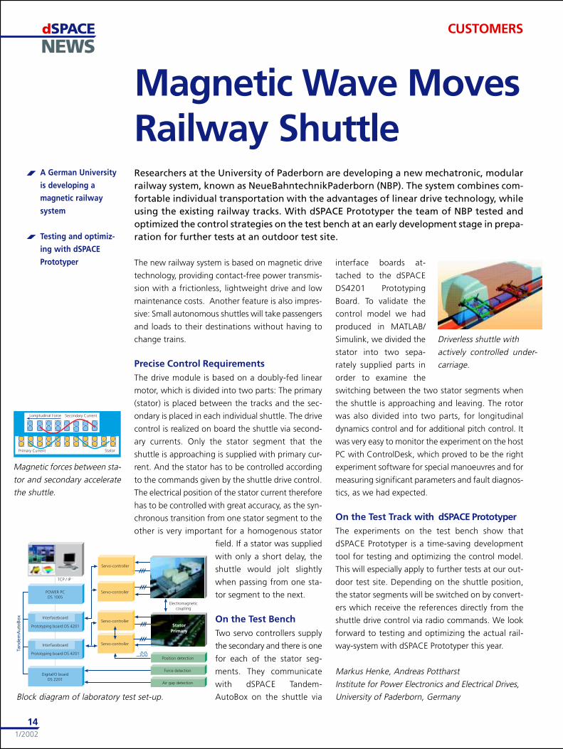
Magnetic forces between sta-
tor and secondary accelerate
the shuttle.
Driverless shuttle with
actively controlled under-
carriage.
Block diagram of laboratory test set-up.
dSPACENEWS
1/2002
15
PRODUCTS
3-D Animation with MotionDeskMotionDesk is our new tool generation for visualiz-
ing real-time simulations on your dSPACE system as
a 3-D online animation. Compared to its predeces-
sor, RealMotion, it provides much more realistic
graphics thanks to textured rendering. The new in-
teractive configuration of cameras and 3-D objects
means that developers get results fast when they set
up the visualization for ECU tests using hardware-in-
the-loop simuation.
An Easy-to-Create 3-D WorldMotionDesk is used for 3-D animations, for instance
in robotics and flight simulation, and in its main ap-
plication: the automotive field. With a high-end
hardware system, MotionDesk is the solution for
”man-in-the-loop” applications because these re-
quire a high frame rate and low latency times be-
tween simulation and visualization.
MotionDesk’s graphical user interface is similar to
other dSPACE tools. It will be easy for you to create
a virtual 3-D world by simply dragging and dropping
objects from a 3-D library to a scene. The library con-
tains the objects you need to create all the driving
scenes you can think of: roads, houses, car bodies
and wheels. Additional objects can easily be added
as the 3-D object geometries are described in the
VRML2 standard. And even existing car geometries
created with CAD systems are usable when con-
verted to VRML2.
Get Realistic Results FastExperience the jump in
3-D online animation
with MotionDesk, to
be released by mid-
March. For informa-
tion regarding migra-
tion from RealMotion
to MotionDesk, please
contact our tech-
nical sales.
If you want more gen-
eral information on
MotionDesk, please
refer to our Website
www.dspace.de.
Realistic 3-D
graphics
Intuitive scene
navigation
MicroAutoBox Now at 300 MHzMicroAutoBox, our in-vehicle hardware for rapid
control prototyping, is now available with a
300 MHz PowerPC Processor, replacing the previous
200 MHz version. This innovation speeds things up
by 10-30% - depending on the application you are
running. The faster CPU requires a slightly higher
power input of typically 9.5 W (formerly 8.5 W). The
resulting physical changes such as temperature are
within the specified limits.
Simple Switch to 300 MHzPrograms or models that were prepared and com-
piled for the 200 MHz MicroAutoBox do not need
to be recompiled. So you can enjoy a trouble-free
changeover to the new 300 MHz MicroAutoBox.
This makes it easy to take advantage of all the well-
tried features of MicroAutoBox like signal condition-
ing for automotive signal levels, bypassing interface,
automatic boot-up and complete software support
– to mention only a few. Small dimensions and the
vibration-resistant construction of MicroAutoBox
make it possible to use it just like an ECU in a real
car. In 2001 dSPACE delivered more than 300
MicroAutoBoxes.
MicroAutoBox has
been on the market
for four years and
is used at BMW,
DaimlerChrysler,
D e l p h i ,
DENSO, Fiat,
Ford, Gen-
eral Motors,
Hella, Nissan, Opel,
V i s t e o n ,
Volkswagen
and many
more.
Speed up your
application by
10-30%
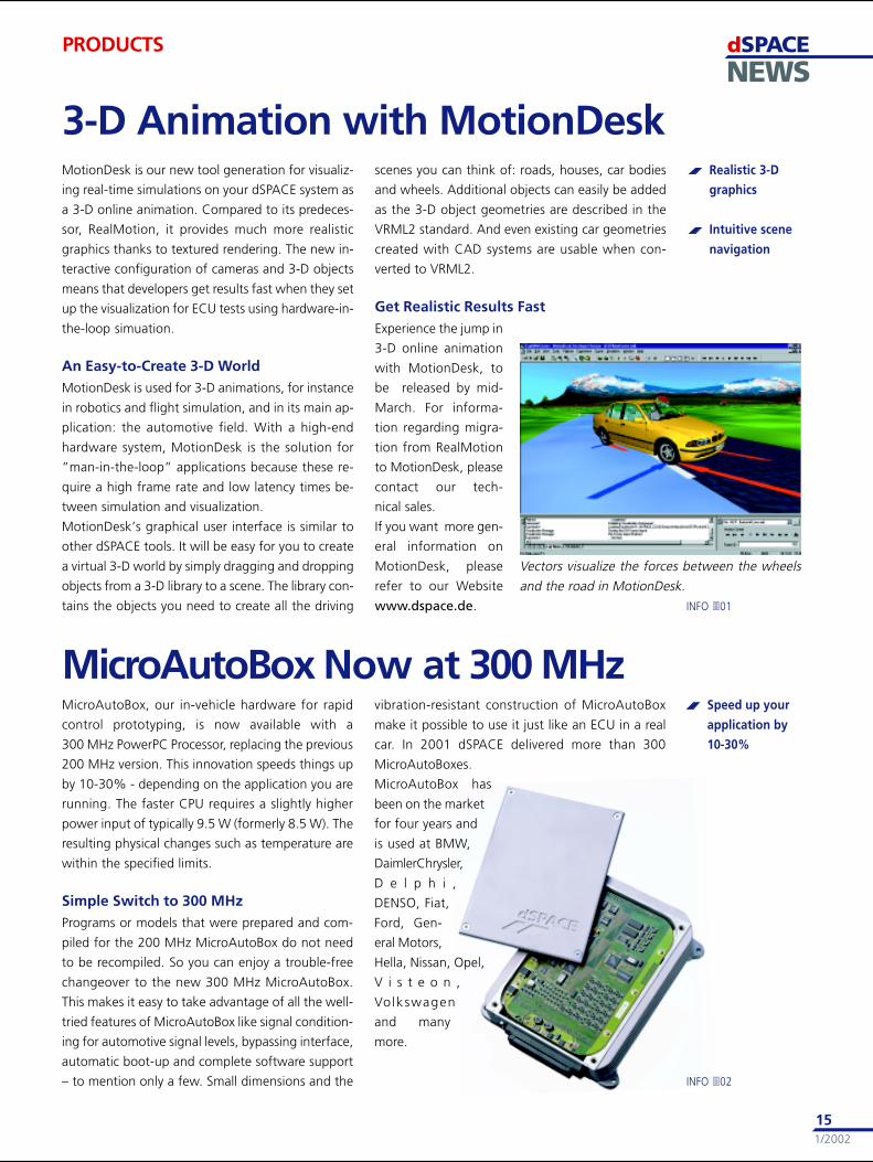
INFO �01
Vectors visualize the forces between the wheels
and the road in MotionDesk.
INFO �02
dSPACENEWS
1/2002
16
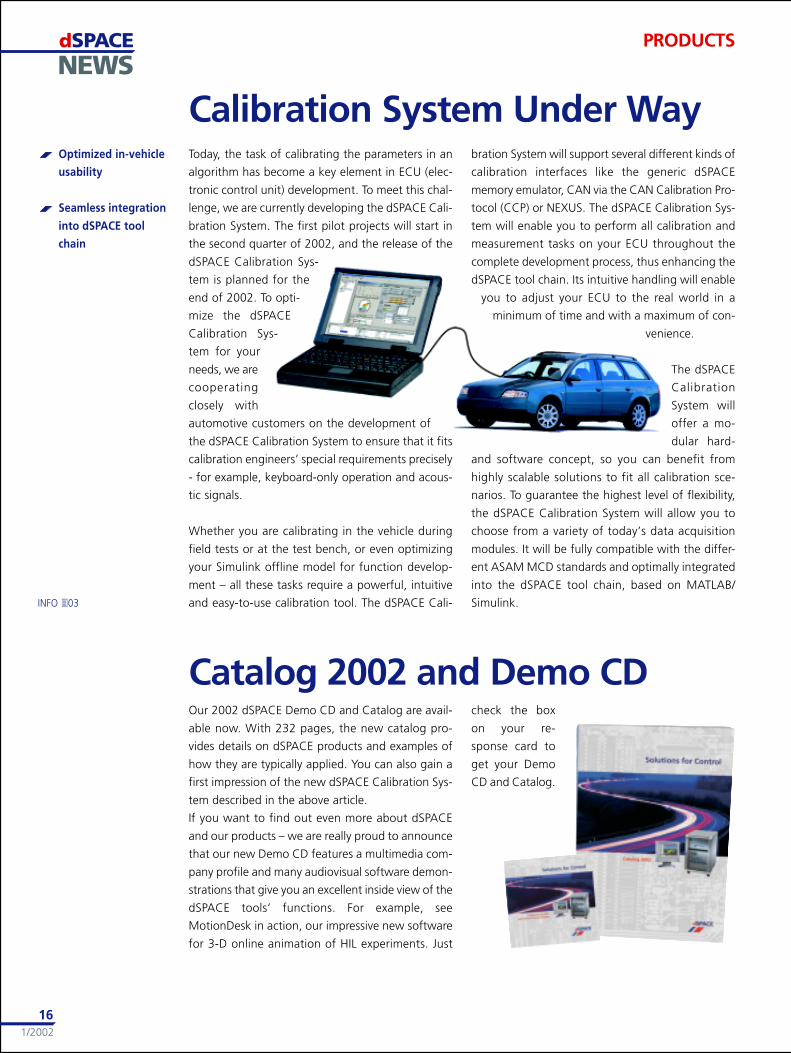
Calibration System Under Way
Catalog 2002 and Demo CD
PRODUCTS
INFO �03
Today, the task of calibrating the parameters in an
algorithm has become a key element in ECU (elec-
tronic control unit) development. To meet this chal-
lenge, we are currently developing the dSPACE Cali-
bration System. The first pilot projects will start in
the second quarter of 2002, and the release of the
dSPACE Calibration Sys-
tem is planned for the
end of 2002. To opti-
mize the dSPACE
Calibration Sys-
tem for your
needs, we are
cooperating
closely with
automotive customers on the development of
the dSPACE Calibration System to ensure that it fits
calibration engineers’ special requirements precisely
- for example, keyboard-only operation and acous-
tic signals.
Whether you are calibrating in the vehicle during
field tests or at the test bench, or even optimizing
your Simulink offline model for function develop-
ment – all these tasks require a powerful, intuitive
and easy-to-use calibration tool. The dSPACE Cali-
bration System will support several different kinds of
calibration interfaces like the generic dSPACE
memory emulator, CAN via the CAN Calibration Pro-
tocol (CCP) or NEXUS. The dSPACE Calibration Sys-
tem will enable you to perform all calibration and
measurement tasks on your ECU throughout the
complete development process, thus enhancing the
dSPACE tool chain. Its intuitive handling will enable
you to adjust your ECU to the real world in a
minimum of time and with a maximum of con-
venience.
The dSPACE
Calibration
System will
offer a mo-
dular hard-
and software concept, so you can benefit from
highly scalable solutions to fit all calibration sce-
narios. To guarantee the highest level of flexibility,
the dSPACE Calibration System will allow you to
choose from a variety of today’s data acquisition
modules. It will be fully compatible with the differ-
ent ASAM MCD standards and optimally integrated
into the dSPACE tool chain, based on MATLAB/
Simulink.
Optimized in-vehicle
usability
Seamless integration
into dSPACE tool
chain
Our 2002 dSPACE Demo CD and Catalog are avail-
able now. With 232 pages, the new catalog pro-
vides details on dSPACE products and examples of
how they are typically applied. You can also gain a
first impression of the new dSPACE Calibration Sys-
tem described in the above article.
If you want to find out even more about dSPACE
and our products – we are really proud to announce
that our new Demo CD features a multimedia com-
pany profile and many audiovisual software demon-
strations that give you an excellent inside view of the
dSPACE tools’ functions. For example, see
MotionDesk in action, our impressive new software
for 3-D online animation of HIL experiments. Just
check the box
on your re-
sponse card to
get your Demo
CD and Catalog.
dSPACENEWS
1/2002
17
BUSINESS
dSPACE Inc. is proud to announce its second North
American User Conference. It will take place on May
16-17, 2002 at the Atheneum Suite Hotel and Con-
ference Center in Detroit, MI. The conference offers
a comprehensive technical program that includes
keynote speakers, user presentations, and developer
highlights on using dSPACE products for the con-
troller development process.
The program is organized into four tracks of discus-
sion: new developments, function development
with dSPACE Prototyper, production code genera-
tion with TargetLink, and automated testing with
dSPACE Simulator. The conference will also host an
interactive panel discussion and an exhibition with
hands-on demonstrations of dSPACE’s latest prod-
ucts. Our call for papers is complete and an agenda
is now available if you have not already received
yours in the mail. Rooms are reserved, and a social
event is planned at Fishbone’s, one of America’s Top
50 Restaurants, that captures the exciting spirit of
Mardi Gras! Qualify for a 30% discount for early
registration, deadline March 29, 2002. So please
join us, contact us at [email protected], call us
at #(248)567-1300, or check out our home page
listed under EVENTS, for more information.
User Conference in the USA
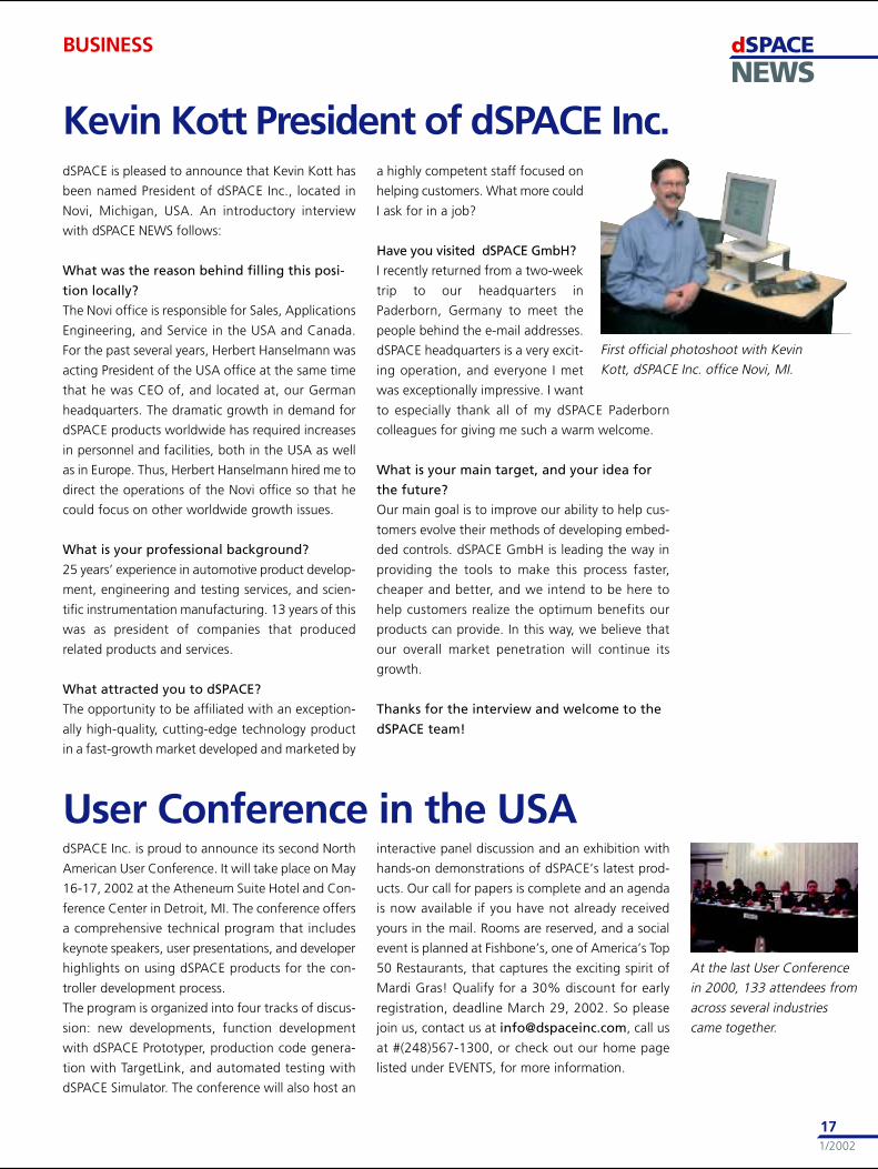
dSPACE is pleased to announce that Kevin Kott has
been named President of dSPACE Inc., located in
Novi, Michigan, USA. An introductory interview
with dSPACE NEWS follows:
What was the reason behind filling this posi-
tion locally?
The Novi office is responsible for Sales, Applications
Engineering, and Service in the USA and Canada.
For the past several years, Herbert Hanselmann was
acting President of the USA office at the same time
that he was CEO of, and located at, our German
headquarters. The dramatic growth in demand for
dSPACE products worldwide has required increases
in personnel and facilities, both in the USA as well
as in Europe. Thus, Herbert Hanselmann hired me to
direct the operations of the Novi office so that he
could focus on other worldwide growth issues.
What is your professional background?
25 years’ experience in automotive product develop-
ment, engineering and testing services, and scien-
tific instrumentation manufacturing. 13 years of this
was as president of companies that produced
related products and services.
What attracted you to dSPACE?
The opportunity to be affiliated with an exception-
ally high-quality, cutting-edge technology product
in a fast-growth market developed and marketed by
a highly competent staff focused on
helping customers. What more could
I ask for in a job?
Have you visited dSPACE GmbH?
I recently returned from a two-week
trip to our headquarters in
Paderborn, Germany to meet the
people behind the e-mail addresses.
dSPACE headquarters is a very excit-
ing operation, and everyone I met
was exceptionally impressive. I want
to especially thank all of my dSPACE Paderborn
colleagues for giving me such a warm welcome.
What is your main target, and your idea for
the future?
Our main goal is to improve our ability to help cus-
tomers evolve their methods of developing embed-
ded controls. dSPACE GmbH is leading the way in
providing the tools to make this process faster,
cheaper and better, and we intend to be here to
help customers realize the optimum benefits our
products can provide. In this way, we believe that
our overall market penetration will continue its
growth.
Thanks for the interview and welcome to the
dSPACE team!
Kevin Kott President of dSPACE Inc.
First official photoshoot with Kevin
Kott, dSPACE Inc. office Novi, MI.
At the last User Conference
in 2000, 133 attendees from
across several industries
came together.
dSPACENEWS
1/2002
18
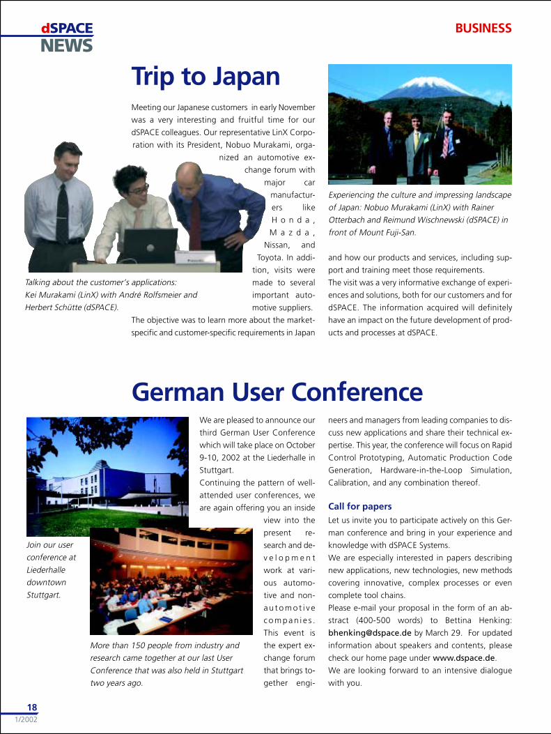
Talking about the customer’s applications:
Kei Murakami (LinX) with André Rolfsmeier and
Herbert Schütte (dSPACE).
Meeting our Japanese customers in early November
was a very interesting and fruitful time for our
dSPACE colleagues. Our representative LinX Corpo-
ration with its President, Nobuo Murakami, orga-
nized an automotive ex-
change forum with
major car
manufactur-
ers like
H o n d a ,
M a z d a ,
Nissan, and
Toyota. In addi-
tion, visits were
made to several
important auto-
motive suppliers.
The objective was to learn more about the market-
specific and customer-specific requirements in Japan
Trip to Japan
BUSINESS
Experiencing the culture and impressing landscape
of Japan: Nobuo Murakami (LinX) with Rainer
Otterbach and Reimund Wischnewski (dSPACE) in
front of Mount Fuji-San.
and how our products and services, including sup-
port and training meet those requirements.
The visit was a very informative exchange of experi-
ences and solutions, both for our customers and for
dSPACE. The information acquired will definitely
have an impact on the future development of prod-
ucts and processes at dSPACE.
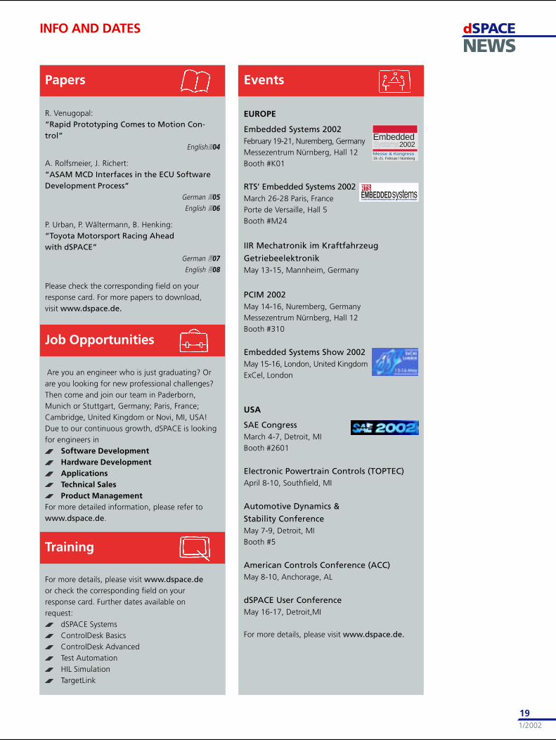
German User ConferenceWe are pleased to announce our
third German User Conference
which will take place on October
9-10, 2002 at the Liederhalle in
Stuttgart.
Continuing the pattern of well-
attended user conferences, we
are again offering you an inside
view into the
present re-
search and de-
v e l o p m e n t
work at vari-
ous automo-
tive and non-
a u t o m o t i v e
c o m p a n i e s .
This event is
the expert ex-
change forum
that brings to-
gether engi-
neers and managers from leading companies to dis-
cuss new applications and share their technical ex-
pertise. This year, the conference will focus on Rapid
Control Prototyping, Automatic Production Code
Generation, Hardware-in-the-Loop Simulation,
Calibration, and any combination thereof.
Call for papersLet us invite you to participate actively on this Ger-
man conference and bring in your experience and
knowledge with dSPACE Systems.
We are especially interested in papers describing
new applications, new technologies, new methods
covering innovative, complex processes or even
complete tool chains.
Please e-mail your proposal in the form of an ab-
stract (400-500 words) to Bettina Henking:
[email protected] by March 29. For updated
information about speakers and contents, please
check our home page under www.dspace.de.
We are looking forward to an intensive dialogue
with you.
Join our user
conference at
Liederhalle
downtown
Stuttgart.
More than 150 people from industry and
research came together at our last User
Conference that was also held in Stuttgart
two years ago.
dSPACENEWS
1/2002
19
EUROPE
Embedded Systems 2002February 19-21, Nuremberg, GermanyMessezentrum Nürnberg, Hall 12Booth #K01
RTS’ Embedded Systems 2002March 26-28 Paris, FrancePorte de Versaille, Hall 5Booth #M24
IIR Mechatronik im Kraftfahrzeug
GetriebeelektronikMay 13-15, Mannheim, Germany
PCIM 2002May 14-16, Nuremberg, GermanyMessezentrum Nürnberg, Hall 12Booth #310
Embedded Systems Show 2002May 15-16, London, United KingdomExCel, London
USA
SAE CongressMarch 4-7, Detroit, MIBooth #2601
Electronic Powertrain Controls (TOPTEC)April 8-10, Southfield, MI
Automotive Dynamics &
Stability ConferenceMay 7-9, Detroit, MIBooth #5
American Controls Conference (ACC)May 8-10, Anchorage, AL
dSPACE User ConferenceMay 16-17, Detroit,MI
For more details, please visit www.dspace.de.
INFO AND DATES
R. Venugopal:“Rapid Prototyping Comes to Motion Con-trol”
English�04
A. Rolfsmeier, J. Richert:“ASAM MCD Interfaces in the ECU SoftwareDevelopment Process”
German �05
English �06
P. Urban, P. Wältermann, B. Henking:“Toyota Motorsport Racing Aheadwith dSPACE”
German �07
English �08
Please check the corresponding field on yourresponse card. For more papers to download,visit www.dspace.de.
Are you an engineer who is just graduating? Orare you looking for new professional challenges?Then come and join our team in Paderborn,Munich or Stuttgart, Germany; Paris, France;Cambridge, United Kingdom or Novi, MI, USA!Due to our continuous growth, dSPACE is lookingfor engineers in
Software DevelopmentHardware DevelopmentApplicationsTechnical SalesProduct Management
For more detailed information, please refer towww.dspace.de.
For more details, please visit www.dspace.deor check the corresponding field on yourresponse card. Further dates available onrequest:
dSPACE SystemsControlDesk BasicsControlDesk AdvancedTest AutomationHIL SimulationTargetLink
Papers Events
Job Opportunities
Training
EmbeddedSystems2002
19.-21. Februar / NürnbergMesse & Kongress
���������������������� �������������������������������������������� ��������������������
���
USA and Canada
dSPACE Inc.28700 Cabot Drive . Suite 1100Novi . MI 48377Tel.: +1 248 567 1300Fax: +1 248 567 [email protected]
United KingdomdSPACE Ltd.2nd Floor Westminster HouseSpitfire Close . Ermine Business ParkHuntingdonCambridgeshire PE29 6XYTel.: +44 1480 410700Fax: +44 1480 [email protected]
Headquarters in Germany
dSPACE GmbHTechnologiepark 2533100 PaderbornTel.: +49 5251 1638-0Fax: +49 5251 [email protected]
FrancedSPACE SarlParc BurospaceBâtiment 17Route de la Plaine de Gisy91573 Bièvres CedexTel.: +33 1 6935 5060Fax: +33 1 6935 [email protected]
dSPACE
AustraliaCEANET Pty Ltd.Level 1, 265 Coronation DriveMiltonQueensland 4064Tel.: +61 7 3369 4499Fax: +61 7 3369 [email protected]
IndiaCranes Software Intern. Ltd.29, 7th Cross, 14th MainVasanthanagarBangalore - 560 052Tel.: +91 80 2381 740Fax: +91 80 2384 [email protected]
KoreaDarim Systems Co., Ltd.Expo VentureTown 3rd Fl.DoRyong-Dong 3-1YuSung-GuTaejonTel.: +82 431 260 4747Fax: +82 431 260 [email protected]
SwedenFENGCO Real Time Control ABHallonbergsplan 10Box 7068SE-174 07 SundbybergTel.: +46 8 6 28 03 15Fax: +46 8 96 73 [email protected]
ChinaChina HiRain Tech. Co. Ltd.Shangfang Plaza No. 27Room 620Bei San Huan Zhong Lu100029 Beijing, P.R. ChinaTel.: +86 10 82 02 19 50Fax:+86 10 62 07 36 00www.hirain.com
IsraelOmikron Delta (1927) Ltd.10 Carlebach St.Tel-Aviv 67132Tel.: +972 3 561 5151Fax:+972 3 561 [email protected]
NetherlandsTSS ConsultancyRietkraag 37NL-3121 TC SchiedamTel.: +31 10 2 47 00 31Fax: +31 10 2 47 00 [email protected]
TaiwanScientific Formosa Incorporation11th Fl. 354 Fu-Shin N. RoadTaipei, Taiwan, R.O.C.Tel.: +886 2 2505 05 25Fax: +886 2 2503 16 [email protected]
Czech and Slovak RepublicHUMUSOFT s.r.o.Novákových 6180 000 Praha 8Tel.: +420 2 84 01 17 30Fax: +420 2 84 01 17 [email protected]
JapanLinX Corporation1-13-11 Eda-nishiAoba-ku, Yokohama-shiKanagawa, 225-0014 JapanTel.: +81 45 979 0731Fax: +81 45 979 [email protected]
PolandONTul. Obozna 1130-011 KrakówTel.: +48 12 632 32 60Fax: +48 12 632 17 [email protected]