Embed Size (px)
Citation preview
Model-based Rack Force Estimation forElectric Power Steering
Steve Fankem ∗ Thomas Weiskircher ∗ Steffen Muller ∗∗
∗ Institute for Mechatronics in Mechanical and AutomotiveEngineering, University of Kaiserslautern, D-67663 Kaiserslautern,
Germany (e-mail: [email protected],[email protected]).
∗∗ Fachgebiet Kraftfahrzeuge, TU Berlin, D-10623 Berlin, Germany(e-mail: [email protected]).
Abstract: In modern cars, hydraulic power steering (HPS) is continuously substituted by theelectric power steering (EPS), active front steering (AFS) or steer-by-wire (SbW). In general,the main task of the EPS/HPS is the support of the driver in controlling the lateral position ofthe car and compensating the tyre aligning torques. These torques result in a steering rack force,which reliable long-term measurement induces disadvantages e.g. high sensor costs. Since theknowledge of the steering rack force is useful to improve various automotive control applications,the estimation of the steering rack force with real-time capable algorithms is in the focus of thisresearch. First, a non-linear dynamic 4-mass model is given and validated by a prototype EPS.Second, an algorithm for steering rack force estimation is introduced using a non-linear frictioncompensation module and a linear disturbance observer. Finally, the estimation algorithm isanalysed by means of validated numerical EPS model, a steering test bench and a real prototypecar. The results state the excellent performance of the estimation algorithm, even under realoperation conditions.
Keywords: steering rack force estimation, steering actuator design, electric power steering
1. INTRODUCTION
Considering all actuators of modern cars, the steeringsystem is the most important one to design the feedback tothe driver and the vehicle manoeuvrability. Additionally,an innovative steering device enables various driver assistfunctions e.g. lane keeping systems or side wind assist.With the additional requirements of future cars as energyconsumption, the conventional hydraulic power steeringis substituted by novel electric powered steering systems.These lead to more precise control of the steering functionsand improved energy efficiency of the steering device.Besides, various types of steering devices like active frontsteering (AFS) or steer-by-wire (SbW) must be consideredwhen new assist functions are developed. A detail analyseof the EPS structure states that extended functionality ispossible with the common steering system sensors e.g. thecurrent-based torque sensor of the power assist motor andthe steering wheel position sensor. Additional to the driverand the power assist torque of the steering system, thetyre-road contact forces are important for various applica-tions, since they include information about the tyre con-tact behaviour to the road. This information is necessaryto design a realistic steering wheel feedback, see Fankemet al. [2013], Hsu et al. [2013]. Secondly, this informationis useful for vehicle dynamics control since it supports theimprovement of road friction estimation, see Weiskircheret al. [2012], Hsu [2010]. Moreover, the knowledge of thesteering rack force is helpful to improve the SbW positioncontrol performance by the use of a closed loop controller
with disturbance rejection. To support these different func-tions, this paper presents a model-based algorithm for real-time estimation of the steering rack force. This is generatedby the tyre aligning torques and the link of the tyres tothe steering rack via the tie rods. Hence in general, twomain methods for model-based estimation of the steeringrack force are possible. The first one uses a detailed vehicledynamics model to calculate the tyre aligning torques andthe kinematic description of the linkage to the steering rackto estimate the rack force, see Koch [2010], Weiskircheret al. [2012]. The disadvantage of this method is thecomprehensive parameter requirement for the vehicle andthe complex tyre-ground interaction, e.g. vehicle mass andsuspension kinematics, tyre side stiffness, road grade, androad slope. Thus, this method is difficult to apply to pro-duction cars. Alternatively, an actuation-based estimationusing the sensors of the steering system only, is a morepromising method, as the actuator has a minor parameteruncertainty as the vehicle. Therefore, this research con-centrates on the second method and introduces a model-based estimation of the reaction force. In this paper, thewidely spread rack assist electric power steering system(EPS) is used to analyse the functionality of the estimationalgorithm. First, a detailed system description includingsystem dynamics modelling is given. The validation isdone by the help of a real prototype EPS mounted on asteering test-bench. Afterward, a non-linear algorithm toestimate the rack force is proposed. Finally, the algorithmis validated by the detailed system model, the steeringsystem test bench and a pre-production car.
Preprints of the 19th World CongressThe International Federation of Automatic ControlCape Town, South Africa. August 24-29, 2014
Copyright © 2014 IFAC 8469
electric machine
belt Tem
Fa,2
RBG
rack
torque sensor
pinion (ipi)
steering wheel
xr
Tha
tie rod
iAPA
δwh (xr)
Fx2
Ta,2
Fa,1
Fy2
(ili)
Tsen
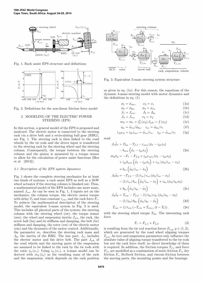
Fig. 1. Rack assist EPS structure and definitions
−0.02 0 0.02−100
−50
0
50
100
v in m/s
b
Ffin
N
−0.03 −0.02 −0.01 0 0.01 0.02−10
−5
0
5
10
v in m/s
a
Ffin
N 0.37(Fs − Fc)
Fs − Fc0.96Fc
v96 vs
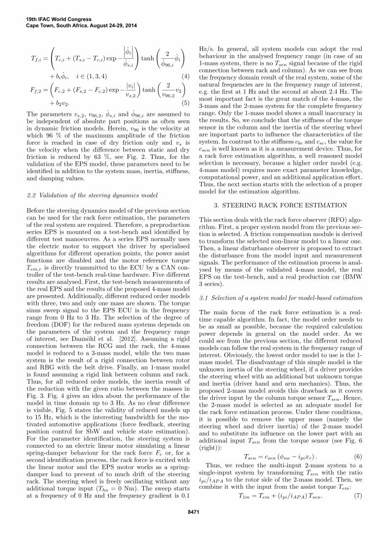
Fig. 2. Definitions for the non-linear friction force model
2. MODELING OF THE ELECTRIC POWERSTEERING (EPS)
In this section, a general model of the EPS is proposed andanalysed. The electric motor is connected to the steeringrack via a drive belt and a recirculating ball gear (RBG),see Fig. 1. The steering rack is then linked to the roadwheels by the tie rods and the driver input is transferredto the steering rack by the steering wheel and the steeringcolumn. Consequently, the torque between the steeringcolumn and the pinion is measured by a torque sensorto allow for the calculation of power assist functions (Hsuet al. [2013]).
2.1 Description of the EPS system dynamics
Fig. 1 shows the complete steering mechanics for at leasttwo kinds of systems: a rack assist EPS as well as a SbWwheel actuator if the steering column is blanked out. Thus,a mathematical model of the EPS includes one more mass,named Jsw. As can be seen in Fig. 1, 3 inputs act on themechanics: the column torque, the electric motor torquewith delay Tt and time constant τem, and the rack force Fr.To achieve the mathematical description of the steeringmodel, the equivalent 5-mass system in Fig. 3 is used.This includes all physical parts of the system: the steeringcolumn with the steering wheel (sw), the torque sensor(sen), the wheel and suspension inertia Jwh, the rack, thescrew ball (ba) and its stiffness and damping, the belt (be)stiffness and damping, the rotor (rot) of the electric motor(em) and the dynamics of the motor control. Additionally,the parameter mr describes the steering rack mass andJba the inertia of the RBG. The last part, Jro includesthe electric motor and the drive belt. The part Jwh ofthe road wheels and the moving parts of the suspensionare assumed to be linked to the rack by the tie rods withthe ratio ili (xr). Using ili (xr), a 4-mass model can bederived with m2 (ili) as the resulting mass of the rackand the suspension, which depends on the rack position
steering column
csc
rack, suspension, wheelsECU rotor screw ball
m2
Tha
Tem,r
Tem
Ta,1
δwh
Tf,wh
Ff,r
xrili
bsc
ipi
bsen
csen
Jwh
Jsw
Jba
Jro
φba
φsw
φro Tf,sw
Tf,ba
Tf,ro
isc
ibe
cbe
bsc mrTa,2
Fig. 3. Equivalent 5-mass steering system structure
as given in eq. (1e). For this reason, the equations of thedynamic 4-mass steering model with motor dynamics andthe definitions in eq. (1)
φ1 = φsw, x2 = xr (1a)
φ3 = φba, φ4 = φro (1b)
J1 = Jsw, J3 = Jba (1c)
J4 = Jro, v2 = x2 (1d)
m2 = mr + i2li (x2) Jwh = f (x2) (1e)
ibe = φro/φba, isc = φba/vr (1f)
iAPA = ibeiscr = φro/vr, ipi = φsw/vr (1g)
read
J1φ1 = Tha − Tf,1 − csen (φ1 − ipix2)
− bsen(φ1 − ipix2
)(2a)
m2x2 = −Fr − Ff,2 + ipicsen (φ1 − ipix2)
+ ipibsen
(φ1 − ipix2
)+ csc (φ3/isc − x2)
+ bsc
(φ3/isc − x2
)(2b)
J3φ3 = −Tf,3 − (1/isc) csc (φ3/isc − x2)
− (1/isc) bsc
(φ3/isc − x2
)+ cbe (φ4/ibeφ3)
+ bbe
(φ4/ibe − φ3
)(2c)
J4φ4 = Tem − Tf,4 − (1/ibe) cbe (φ4/ibe − φ3)
− (1/ibe) bbe
(φ4/ibe − φ3
)(2d)
Tem = 1/τem (−Tem + Tem,r (t− Tt)) . (2e)
with the steering wheel torque Tha. The interesting rackforce
Fr = Fa,1 + Fa,2 (3)
is resulting from the tie rod reaction forces Fa,q, q ∈ (1, 2),which are generated by the road wheel aligning torquesTa,q. As tyre and suspension parameters only influence theabsolute value of aligning torque transferred to the tie rodsbut not the rack force itself, no direct knowledge of themis required. In addition, the friction torques Tf,i and forceFf,i are modelled as a combination of static friction Fs, dryfriction Fc, Stribeck friction, and viscous friction betweenthe moving parts, the mounting points and the bearings:
19th IFAC World CongressCape Town, South Africa. August 24-29, 2014
8470
Tf,i =
Tc,i + (Ts,i − Tc,i) exp−
∣∣∣φi∣∣∣φs,i
tanh
(2
φ96,iφi
)+ biφi, i ∈ (1, 3, 4) (4)
Ff,2 =
(Fc,2 + (Fs,2 − Fc,2) exp− |vi|
vs,2
)tanh
(2
v96,2v2
)+ b2v2. (5)
The parameters vs,2, v96,2, φs,i and φ96,i are assumed tobe independent of absolute part positions as often seenin dynamic friction models. Herein, v96 is the velocity atwhich 96 % of the maximum amplitude of the frictionforce is reached in case of dry friction only and vs isthe velocity when the difference between static and dryfriction is reduced by 63 %, see Fig. 2. Thus, for thevalidation of the EPS model, these parameters need to beidentified in addition to the system mass, inertia, stiffness,and damping values.
2.2 Validation of the steering dynamics model
Before the steering dynamics model of the previous sectioncan be used for the rack force estimation, the parametersof the real system are required. Therefore, a preproductionseries EPS is mounted on a test-bench and identified bydifferent test manoeuvres. As a series EPS normally usesthe electric motor to support the driver by specialisedalgorithms for different operation points, the power assistfunctions are disabled and the motor reference torqueTem,r is directly transmitted to the ECU by a CAN con-troller of the test-bench real-time hardware. Five differentresults are analysed. First, the test-bench measurements ofthe real EPS and the results of the proposed 4-mass modelare presented. Additionally, different reduced order modelswith three, two and only one mass are shown. The torquesinus sweep signal to the EPS ECU is in the frequencyrange from 0 Hz to 3 Hz. The selection of the degree offreedom (DOF) for the reduced mass systems depends onthe parameters of the system and the frequency rangeof interest, see Dannohl et al. [2012]. Assuming a rigidconnection between the RCG and the rack, the 4-massmodel is reduced to a 3-mass model, while the two masssystem is the result of a rigid connection between rotorand RBG with the belt drive. Finally, an 1-mass modelis found assuming a rigid link between column and rack.Thus, for all reduced order models, the inertia result ofthe reduction with the given ratio between the masses inFig. 3. Fig. 4 gives an idea about the performance of themodel in time domain up to 3 Hz. As no clear differenceis visible, Fig. 5 states the validity of reduced models upto 15 Hz, which is the interesting bandwidth for the mo-tivated automotive applications (force feedback, steeringposition control for SbW and vehicle state estimation).For the parameter identification, the steering system isconnected to an electric linear motor simulating a linearspring-damper behaviour for the rack force Fr or, for asecond identification process, the rack force is excited withthe linear motor and the EPS motor works as a spring-damper load to prevent of to much drift of the steeringrack. The steering wheel is freely oscillating without anyadditional torque input (Tha = 0 Nm). The sweep startsat a frequency of 0 Hz and the frequency gradient is 0.1
Hz/s. In general, all system models can adopt the realbehaviour in the analysed frequency range (in case of an1-mass system, there is no Tsen signal because of the rigidconnection between rack and column). As we can see fromthe frequency domain result of the real system, some of thenatural frequencies are in the frequency range of interest,e.g. the first at 1 Hz and the second at about 2.4 Hz. Themost important fact is the great match of the 4-mass, the3-mass and the 2-mass system for the complete frequencyrange. Only the 1-mass model shows a small inaccuracy inthe results. So, we conclude that the stiffness of the torquesensor in the column and the inertia of the steering wheelare important parts to influence the characteristics of thesystem. In contrast to the stiffness cbe and csc, the value forcsen is well known as it is a measurement device. Thus, fora rack force estimation algorithm, a well reasoned modelselection is necessary, because a higher order model (e.g.4-mass model) requires more exact parameter knowledge,computational power, and an additional application effort.Thus, the next section starts with the selection of a propermodel for the estimation algorithm.
3. STEERING RACK FORCE ESTIMATION
This section deals with the rack force observer (RFO) algo-rithm. First, a proper system model from the previous sec-tion is selected. A friction compensation module is derivedto transform the selected non-linear model to a linear one.Then, a linear disturbance observer is proposed to extractthe disturbance from the model input and measurementsignals. The performance of the estimation process is anal-ysed by means of the validated 4-mass model, the realEPS on the test-bench, and a real production car (BMW3 series).
3.1 Selection of a system model for model-based estimation
The main focus of the rack force estimation is a real-time capable algorithm. In fact, the model order needs tobe as small as possible, because the required calculationpower depends in general on the model order. As wecould see from the previous section, the different reducedmodels can follow the real system in the frequency range ofinterest. Obviously, the lowest order model to use is the 1-mass model. The disadvantage of this simple model is theunknown inertia of the steering wheel, if a driver providesthe steering wheel with an additional but unknown torqueand inertia (driver hand and arm mechanics). Thus, theproposed 2-mass model avoids this drawback as it coversthe driver input by the column torque sensor Tsen. Hence,the 2-mass model is selected as an adequate model forthe rack force estimation process. Under these conditions,it is possible to remove the upper mass (namely thesteering wheel and driver inertia) of the 2-mass modeland to substitute its influence on the lower part with anadditional input Tsen from the torque sensor (see Fig. 6(right)):
Tsen = csen (φsw − ipixr) . (6)
Thus, we reduce the multi-input 2-mass system to asingle-input system by transforming Tsen with the ratioipi/iAPA to the rotor side of the 2-mass model. Then, wecombine it with the input from the assist torque Tem:
T1m = Tem + (ipi/iAPA)Tsen. (7)
19th IFAC World CongressCape Town, South Africa. August 24-29, 2014
8471
0 5 10 15 20 25 30−400
−200
0
200
400
time in s
rotor speed
φ4in
rpm
real4-mass3-mass2-mass1-mass
0 5 10 15 20 25 30
−5
0
5
time in s
Tsenin
Nm
sensor torque
real4-mass3-mass2-mass
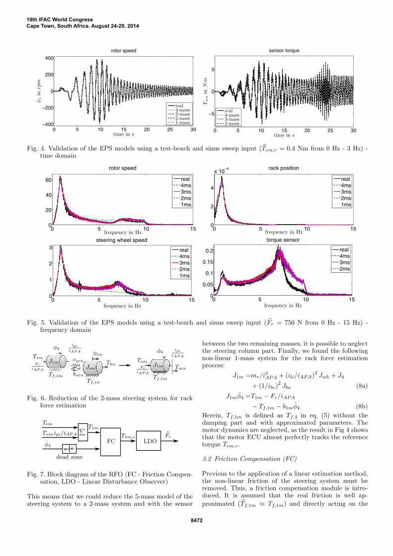
Fig. 4. Validation of the EPS models using a test-bench and sinus sweep input (Tem,r = 0.4 Nm from 0 Hz - 3 Hz) -time domain
0 5 10 150
20
40
60
frequency in Hz
rotor speed
0 5 10 150
2
4
x 10−4
frequency in Hz
rack position
0 5 10 150
1
2
3
frequency in Hz
steering wheel speed
0 5 10 150
0.05
0.1
0.15
0.2
frequency in Hz
torque sensor
real4ms3ms2ms1ms
real4ms3ms2ms1ms
real4ms3ms2ms1ms
real4ms3ms2ms
Fig. 5. Validation of the EPS models using a test-bench and sinus sweep input (Fr = 750 N from 0 Hz - 15 Hz) -frequency domain
Tem
FriAPA
ipiiAPA
bsen
csenJsw
J1m
φsw
φ4
Tf,sw
Tf,1m
TemJ1m
φ4
Tf,1m
Tsen
ipiiAPA
FriAPA
Tha
Fig. 6. Reduction of the 2-mass steering system for rackforce estimation
LDOFrT1m,c
FC
Tsenipi/iAPA
φ4
Tem ∑
dead zone
T1m
Fig. 7. Block diagram of the RFO (FC - Friction Compen-sation, LDO - Linear Disturbance Observer)
This means that we could reduce the 5-mass model of thesteering system to a 2-mass system and with the sensor
between the two remaining masses, it is possible to neglectthe steering column part. Finally, we found the followingnon-linear 1-mass system for the rack force estimationprocess:
J1m =mr/i2APA + (ili/iAPA)
2Jwh + J4
+ (1/ibe)2Jba (8a)
J1mφ4 =T1m − Fr/iAPA− Tf,1m − b1mφ4 (8b)
Herein, Tf,1m is defined as Tf,4 in eq. (5) without thedamping part and with approximated parameters. Themotor dynamics are neglected, as the result in Fig 4 showsthat the motor ECU almost perfectly tracks the referencetorque Tem,r.
3.2 Friction Compensation (FC)
Previous to the application of a linear estimation method,the non-linear friction of the steering system must beremoved. Thus, a friction compensation module is intro-duced. It is assumed that the real friction is well ap-
proximated (Tf,1m ≈ Tf,1m) and directly acting on the
19th IFAC World CongressCape Town, South Africa. August 24-29, 2014
8472
0 5 10 15 20 25 30−0.5
0
0.5
time [s]
T1m
[Nm]
input torque
T1m,real
T1m,4−mass
0 5 10 15 20 25 30−0.5
0
0.5
time [s]
observer input torque (4−mass sim)
T1m
,c[N
m]
T1m,c
Tf,1m
0 5 10 15 20 25 30
−2000
−1000
0
1000
2000
time [s]
rack force (4−mass sim)
Fr[N
]
0 5 10 15 20 25 30
−2000
−1000
0
1000
2000
time [s]
rack force (test bench)
Fr[N
]
4−massRFO
measRFO
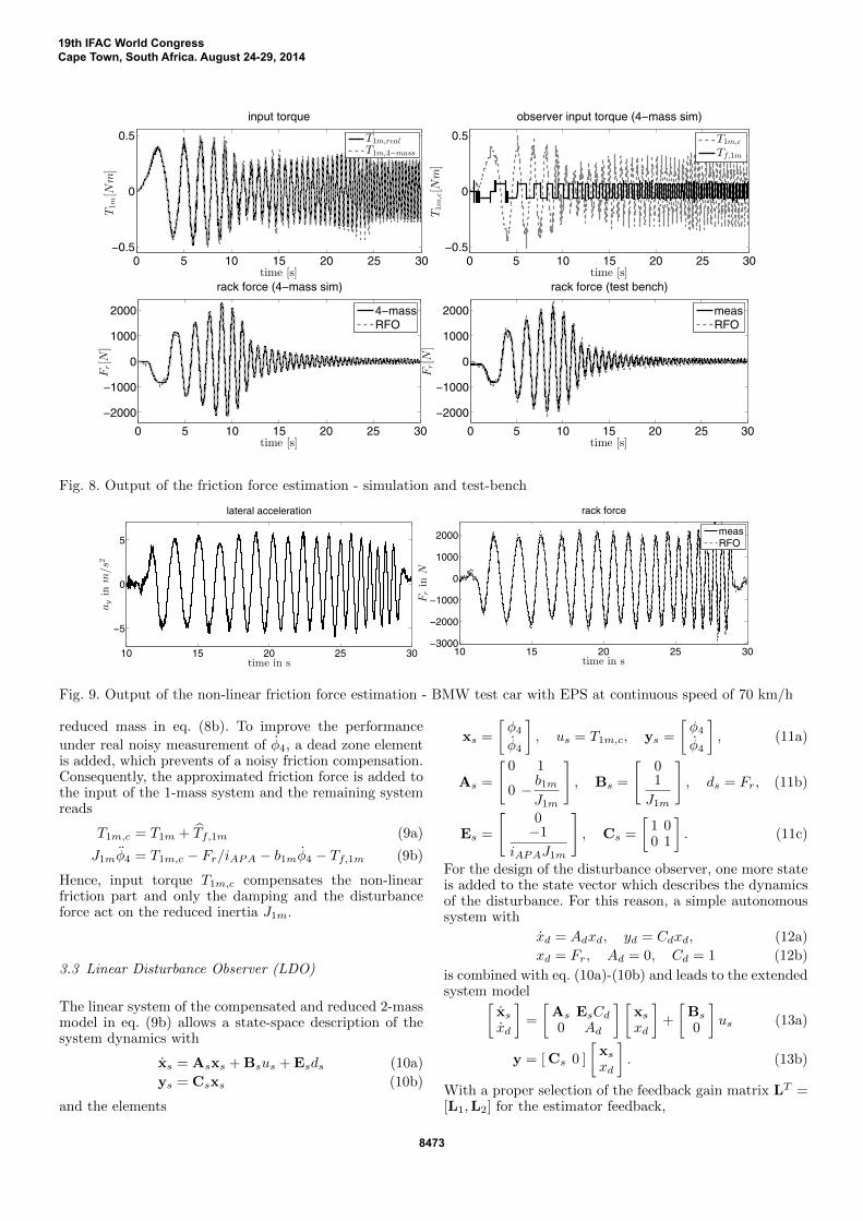
Fig. 8. Output of the friction force estimation - simulation and test-bench
10 15 20 25 30
−5
0
5
lateral acceleration
time in s
ayin
m/s2
10 15 20 25 30−3000
−2000
−1000
0
1000
2000
time in s
Frin
N
rack force
measRFO
Fig. 9. Output of the non-linear friction force estimation - BMW test car with EPS at continuous speed of 70 km/h
reduced mass in eq. (8b). To improve the performance
under real noisy measurement of φ4, a dead zone elementis added, which prevents of a noisy friction compensation.Consequently, the approximated friction force is added tothe input of the 1-mass system and the remaining systemreads
T1m,c = T1m + Tf,1m (9a)
J1mφ4 = T1m,c − Fr/iAPA − b1mφ4 − Tf,1m (9b)
Hence, input torque T1m,c compensates the non-linearfriction part and only the damping and the disturbanceforce act on the reduced inertia J1m.
3.3 Linear Disturbance Observer (LDO)
The linear system of the compensated and reduced 2-massmodel in eq. (9b) allows a state-space description of thesystem dynamics with
xs = Asxs + Bsus + Esds (10a)
ys = Csxs (10b)
and the elements
xs =
[φ4φ4
], us = T1m,c, ys =
[φ4φ4
], (11a)
As =
[0 1
0 − b1mJ1m
], Bs =
[01
J1m
], ds = Fr, (11b)
Es =
[0−1
iAPAJ1m
], Cs =
[1 00 1
]. (11c)
For the design of the disturbance observer, one more stateis added to the state vector which describes the dynamicsof the disturbance. For this reason, a simple autonomoussystem with
xd = Adxd, yd = Cdxd, (12a)
xd = Fr, Ad = 0, Cd = 1 (12b)
is combined with eq. (10a)-(10b) and leads to the extendedsystem model[
xsxd
]=
[As EsCd0 Ad
] [xsxd
]+
[Bs
0
]us (13a)
y = [ Cs 0 ]
[xsxd
]. (13b)
With a proper selection of the feedback gain matrix LT =[L1,L2] for the estimator feedback,
19th IFAC World CongressCape Town, South Africa. August 24-29, 2014
8473
ue =
[L1
L2
](y − y) , y = [ Cs 0 ]
[xsxd
](14)
the disturbance observer state-space equation with speedsensor and position sensor feedback reads[
˙xs˙xd
]=
[As − L1Cs EsCd−L2Cs Ad
] [xsxd
]+
[Bs
0
]us +
[L1
L2
]y. (15a)
A detailed derivation of this structure can be found inFranklin et al. [2010]. The feedback gain matrix is calcu-lated by the linear quadratic estimator (LQE) method toallow for an easy variation of the weighting between thestates and measurements of the system.
4. VALIDATION OF THE RACK FORCEESTIMATION
4.1 Numerical simulation results
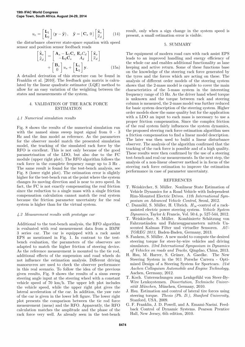
Fig. 8 shows the results of the numerical simulation runwith the named sinus sweep input signal from 0 - 3Hz and the 4ms model as reference. As the parametersfor the observer model match the presented simulationmodel, the tracking of the simulated rack force by theRFO is excellent. This is not only because of the goodparametrisation of the LDO, but also due to the FCmodule (upper right plot). The RFO algorithm follows therack force in the complete frequency range up to 3 Hz .The same result is found for the test-bench analysis, seeFig. 8 (lower right plot). The estimation error is slightlyhigher for the test-bench run at the point where the systemchanges its moving direction and is near to zero speed. Infact, the FC is not exactly compensating the real frictionsince the reduction to a single mass with a single frictioncompensation calculation cannot match the real systembecause the friction parameter uncertainty for the realsystem is higher than for the virtual system.
4.2 Measurement results with prototype car
Additional to the test-bench analysis, the RFO algorithmis evaluated with real measurement data from a BMW3 series car. The car is equipped with a rack assistEPS as mentioned in Fig. 1. In contrast to the test-bench evaluation, the parameters of the observers areadapted to match the higher friction of steering device.As the reference measurement is mounted to the tie rod,additional effects of the suspension and road wheels donot influence the estimation analysis. Different drivingmanoeuvres are used to check the observer performancein this real scenario. To follow the idea of the previousgiven results, Fig. 9 shows the results of a sinus sweepsteering angle input at the steering wheel with a constantvehicle speed of 70 km/h. The upper left plot includesthe vehicle speed, while the upper right plot gives thelateral acceleration of the car. In addition, the yaw rateof the car is given in the lower left figure. The lower rightplot presents the comparison between the tie rod forcemeasurement (meas) and the RFO. Apparently, the RFOcalculation matches the amplitude and the phase of therack force very well. As already seen in the test-bench
result, only when a sign change in the system speed ispresent, a small estimation error is visible.
5. SUMMARY
The equipment of modern road cars with rack assist EPSleads to an improved handling and energy efficiency ofthe whole car and enables additional functionality as lanekeeping and active return. Some of these functions baseon the knowledge of the steering rack force generated bythe tyres and the forces which are acting on these. Theanalysis of different order models of the steering systemshows that the 2-mass model is capable to cover the maincharacteristics of the 5-mass system in the interestingfrequency range of 15 Hz. As the driver hand wheel torqueis unknown and the torque between rack and steeringcolumn is measured, the 2-mass model was further reducedfor basic system description of the steering system. Higherorder models show the same quality but for the applicationwith a LDO an input to each mass is necessary to use aproper friction compensation. Since the complex frictionof the real system fairly influences the system dynamics,the proposed steering rack force estimation algorithm usesa friction compensation to find a linear model description.The later was then used to build a linear disturbanceobserver. The analysis of the algorithm confirmed that thetracking of the rack force is possible and of a high quality.These results were then confirmed by the use of a steeringtest-bench and real car measurements. In the next step, theanalysis of a non-linear observer method is in focus of thesteering rack force estimation to improve the estimationperformance in case of parameter uncertainty.
REFERENCES
T. Weiskircher, S. Muller. Nonlinear State Estimation ofVehicle Dynamics for a Road Vehicle with IndependentRim-Mounted Electric Drives. 11th International Sym-posium on Advanced Vehicle Control, Seoul, 2012.
C. Dannohl, S. Muller, H. Ulbrich. H∞-control of a rack-assisted electric power steering system. Vehicle SystemDynamics, Taylor & Francis, Vol. 50:4, p. 527-544, 2012.
T. Weiskircher, S. Muller. Kombinierte Schatzung vonFahrzustanden und Fahrzeugparametern mittels Un-scented Kalman Filter und virtueller Sensoren. AU-TOREG 2013, Baden-Baden, Germany, 2013.
S. Fankem, S. Muller. A new model to compute the desiredsteering torque for steer-by-wire vehicles and drivingsimulators. 23rd International Symposium in Dynamicsof Vehicles on roads and Tracks, Qingdao, China, 2013.
H. Hsu, M. Harrer, S. Gruner, A. Gaedke. The NewSteering System in the 911 Porsche Carrera - Opti-mized Design of a Steering System for Sportcars. 21stAachen Colloquium Automobile and Engine Technology,Aachen, Germany, 2012.
T. Koch. Untersuchungen zum Lenkgefuhl von Steer-By-Wire Lenksystemen. Dissertation, Technische Univer-sitat Munchen, Munchen, Germany, 2010.
J. Hsu. Estimation and control of lateral tire forces usingsteering torque. Thesis (Ph. D.), Stanford University,Stanford, USA, 2009.
G. F. Franklin, J. D. Powell, and A. Emami-Naeini. Feed-back Control of Dynamic Systems. Pearson PrenticeHall, New Jersey, 6th edition, 2010.
19th IFAC World CongressCape Town, South Africa. August 24-29, 2014
8474