Embed Size (px)
Citation preview
Model-Based Recognition in Robot Vision
ROLAND T. CHIN
Electrical and Computer Engineering Department, University of Wisconsin, Madison, Wisconsin 53706
CHARLES R. DYER
Computer Sciences Department, University of Wisconsin, Madison, Wisconsin 53706
This paper presents a comparative study and survey of model-based object-recognition algorithms for robot vision. The goal of these algorithms is to recognize the identity, position, and orientation of randomly oriented industrial parts. In one form this is commonly referred to as the “bin-picking” problem, in which the parts to be recognized are presented in a jumbled bin. The paper is organized according to 2-D, 2&D, and 3-D object representations, which are used as the basis for the recognition algorithms. Three central issues common to each category, namely, feature extraction, modeling, and matching, are examined in detail. An evaluation and comparison of existing industrial part-recognition systems and algorithms is given, providing insights for progress toward future robot vision systems.
Categories and Subject Descriptors: 1.2.9 [Artificial Intelligence]: Robotics-sensors; 1.2.10 [Artificial Intelligence]: Vision and Scene Understanding-modeling and recovery of physical attributes; 1.4.6 [Image Processing]: Segmentation; 1.4.7 [Image Processing]: Feature Measurement-inuariants; size and shape; texture; 1.4.8 [Image Processing]: Scene Analysis; 1.5.4 [Pattern Recognition]: Applications-computer vision
General Terms: Algorithms
Additional Key Words and Phrases: Bin picking, computer vision, 2-D, 2&D, and 3-D representations, feature extraction, industrial part recognition, matching, model-based image understanding, modeling, robot vision
INTRODUCTION mation do exist, their capabilities are still
Research and development in computer vision has increased dramatically over the last thirty years. Application areas that have been extensively studied include char- acter recognition, medical diagnosis, target detection, and remote sensing. Recently, machine vision for automating the manu- facturing process has received considerable attention with the growing interest in ro- botics. Although some commercial vision systems for robotics and industrial auto-
very primitive. One reason for this slow progress is that many manufacturing tasks require sophisticated visual interpretation, yet demand low cost and high speed, accu- racy, and flexibility. The following deline- ates some of these requirements:
l Speed. The processing speed of acquiring and analyzing an image must be compa- rable to the speed of execution of the specific task. Often, this “real-time” rate is less than fractions of a second per part.
Permission to copy without fee all or part of this material is granted provided that the copies are not made or distributed for direct commercial advantage, the ACM copyright notice and the title of the publication and its date appear, and notice is given that copying is by permission of the Association for Computing Machinery. To copy otherwise, or to republish, requires a fee and/or specific permission. 0 1986 ACM 0360-0300/86/0300-0067 $00.75
Computing Surveys, Vol. 18, No. 1, March 1986
68 l R. T. Chin and C. R. Dyer
CONTENTS
INTRODUCTION 1. MODEL-BASED OBJECT RECOGNITION 2. MODELS, FEATURES, AND MATCHING 3. 2-D IMAGE REPRESENTATIONS
3.1 Examples of Global Feature Methods 3.2 Examples of Structural Feature Methods 3.3 Examples of Relational Graph Methods 3.4 Comparison of the Three Methods
for 2-D Object Representation 4. 2%-D SURFACE REPRESENTATIONS
4.1 Example 1: A Relational Surface Patch Model
4.2 Example 2: A Relational Surface Boundary Model
4.3 Other Studies 5. 3-D OBJECT REPRESENTATIONS
5.1 Example 1: A Surface Patch Graph Model 5.2 Example 2: Hierarchical Generalized
Cylinders 5.3 Example 3: Multiview Feature Vectors 5.4 Example 4: Multiview Surface Orientation
Features 5.5 Other Studies
6. RELATED SURVEYS I. SUMMARY ACKNOWLEDGMENTS REFERENCES
l Accuracy. The recognition rate of objects in the scene and the accuracy in deter- mining parts’ locations and orientations must be high. Although there are in- stances where engineering solutions can be applied to improve accuracy (e.g., by controlling lighting and positional uncer- tainty), these solutions may not be real- istic in terms of the actual environment in which these tasks must be performed.
l Flexibility. The vision system must be flexible enough to accommodate varia- tions in the physical dimensions of mul- tiple copies of a given part, as well as uncertainties in part placement due to individual workstation configurations. Furthermore, many robot vision tasks are distinguished by their performance in dirty and uncontrolled environments.
To be fully effective, future robot vision systems must be able to handle complex industrial parts. This includes recognizing various types of parts and determining their position and orientation in industrial
environments. In addition, vision systems must be able to extract and locate salient features of parts in order to establish spa- tial references for assembly and handling operations and be able to verify the success of these operations.
The performance requirements indicated above are not the only factors distinguish- ing robot vision from other application areas and general computer vision research. The nature of the domain of objects must also be recognized. Most industrial parts-recognition systems are model-based systems in which recognition involves matching the input image with a set of predefined models of parts. The goal of such systems is to precompile a description of each of a known set of industrial parts, then to use these object models to recognize in an image each instance of an object and to specify its position and orientation rel- ative to the viewer. In an industrial envi- ronment the following types of constraints and properties that distinguish this prob- lem domain are usually found:
l The number of parts in a given domain is usually small (l-50).
l Parts may be exactly specified, with known tolerances on particular dimen- sions and features.
l Parts often have distinctive features (e.g., holes and corners), which are commonly found on many different types of parts.
l In scenes containing multiple parts, there are a number of possible configurations (e.g., touching parts, overlapping parts, and parts at arbitrary orientations with respect to one another and the camera).
A growing number of studies have been conducted investigating various approaches to machine recognition of industrial parts. The body of literature generated from this developing field is both vast and scattered. Numerous journal publications have dis- cussed issues involved in industrial vision system design and requirements. A sig- nificant number of research activities have been reported on the development of prototype systems for certain specific in- dustrial applications. These studies are concerned with providing pragmatic solu- tions to current problems in industrial
Computing Surveys, Vol. 18, No. 1, March 1986
Model-Based Recognition in Robot Vision 69
vision. Some of them show the adequacy of image-processing techniques and the avail- ability of technology needs for practical automation systems. Others are concerned with the development of more general parts-recognition algorithms that work in less controlled environments.
While several related survey papers have been published on the topic of robot vision and industrial-parts recognition (see Sec- tion 6), this paper presents a broader and more comprehensive approach to this subject. We concentrate on a comparative survey of techniques for model-based rec- ognition of industrial parts. Related topics that are largely or entirely omitted from this paper are (a) industrial visual inspec- tion applications, methodologies, and sys- tems; (b) machine vision applications and research activities in private industry that have not been published; (c) the role of software and hardware implementation and the use of special-purpose optical and digi- tal imaging devices; (d) the use of other sensory data (e.g., tactile data) as addi- tional aids for recognition; and (e) the examination of the economic, social, and strategic issues that justify the use of robot vision.
parts. Without using properties of the sur- face, many recognition tasks cannot be ac- complished by machine vision. It can be concluded that the dimensionality of spa- tial description and representation is highly dependent on both the particular applica- tion and its intended level of accomplish- ment. Many levels of spatial description (2-D, 3-D, and intermediate levels that fill the gap that exists between images and physical objects) are needed to fulfill var- ious tasks. See, for example, Binford [ 19821, Brady [1982b], and Tenenbaum et al. [1979] for more discussion of the limitations of current robot vision systems.
1. MODEL-BASED OBJECT RECOGNITION
Three central issues arise as a conse- quence of the problems mentioned above: (1) What features should be extracted from an image in order to describe physical prop- erties and their spatial relations in a scene adequately? (2) What constitutes an ade- quate representation of these features and their relationships for characterizing a se- mantically meaningful class of objects; that is, in what form should features be com- bined into object models such that this de- scription is appropriate for recognizing all objects in the given class? (3) How should the correspondence or matching be done between image features and object models in order to recognize the parts in a complex scene?
A number of factors limit the competence In this paper we discuss a variety of of current recognition systems for complex solutions to these issues. It is conven- industrial parts. One of the major limita- ient to categorize all industrial parts- tions is the low dimensionality in spatial recognition systems into several classes representation and description of parts. before focusing on their problems, require- Simple objects presented against a high- ments, limitations, and achievements. The contrast background with no occlusion are selected cases fall into three categories on recognized by extracting simple 2-D fea- the basis of their dimensionality of spatial tures, which are matched against 2-D object description. To be more specific, we have models. The lack of higher dimensional grouped the reported studies into three spatial descriptions (e.g., 3-D volumet- classes: 2-D, 2&D, and 3-D representations, ric representations) and their associated presented in Sections 3, 4, and 5, respec- matching and feature extraction algorithms tively. It is natural to organize the studies restrict the system’s capabilities to a lim- in this fashion since systems within each ited class of objects observed from a few class usually make similar assumptions. fixed viewpoints. The ability to recognize a The grouping is also intended to provide wide variety of rigid parts independent of the readers with an easy understanding of viewpoint demands the ability to extract the state-of-the-art technology related to view-invariant 3-D features and match industrial parts recognition. Associated them with features of 3-D object models. with each category are issues related to Another problem is the lack of descriptions feature extraction, modeling, and match- of surface characteristics of industrial ing, and these are discussed in detail.
Computing Surveys, Vol. 18, No. 1, March 1986
70 . R. T. Chin and C. R. Dyer
r \ Model-Based
Object Recognition
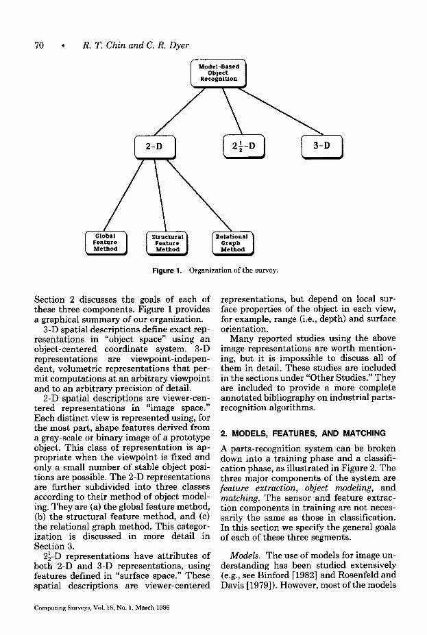
Figure 1. Organization of the survey.
Section 2 discusses the goals of each of these three components. Figure 1 provides a graphical summary of our organization.
3-D spatial descriptions define exact rep- resentations in “object space” using an object-centered coordinate system. 3-D representations are viewpoint-indepen- dent, volumetric representations that per- mit computations at an arbitrary viewpoint and to an arbitrary precision of detail.
2-D spatial descriptions are viewer-cen- tered representations in “image space.” Each distinct view is represented using, for the most part, shape features derived from a gray-scale or binary image of a prototype object. This class of representation is ap- propriate when the viewpoint is fixed and only a small number of stable object posi- tions are possible. The 2-D representations are further subdivided into three classes according to their method of object model- ing. They are (a) the global feature method, (b) the structural feature method, and (c) the relational graph method. This categor- ization is discussed in more detail in Section 3.
2$-D representations have attributes of both 2-D and 3-D representations, using features defined in “surface space.” These spatial descriptions are viewer-centered
representations, but depend on local sur- face properties of the object in each view, for example, range (i.e., depth) and surface orientation.
Many reported studies using the above image representations are worth mention- ing, but it is impossible to discuss all of them in detail. These studies are included in the sections under “Other Studies.” They are included to provide a more complete annotated bibliography on industrial parts- recognition algorithms.
2. MODELS, FEATURES, AND MATCHING
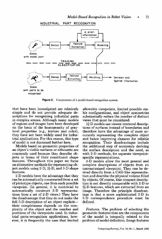
A parts-recognition system can be broken down into a training phase and a classifi- cation phase, as illustrated in Figure 2. The three major components of the system are feature extraction, object modeling, and matching. The sensor and feature extrac- tion components in training are not neces- sarily the same as those in classification. In this section we specify the general goals of each of these three segments.
Models. The use of models for image un- derstanding has been studied extensively (e.g., see Binford [ 19821 and Rosenfeld and Davis [ 19791). However, most of the models
Computing Surveys, Vol. 18, No. 1, March 1986
Model-Based Recognition in Robot Vision l 71
INDUSTRIAL PART RECOGNITION
I Feature
Extraction
t Modeling
J Scene
with model part
Scene with parts to be
recognized
Figure 2. Components of a model-based recognition system.
that have been investigated are relatively simple and do not provide adequate de- scriptions for recognizing industrial parts in complex scenes. Although many models of regions and images have been developed on the basis of the homogeneity of gray- level properties (e.g., texture and color), they have not been widely used for indus- trial applications. For this reason, this type of model is not discussed further here.
Models based on geometric properties of an object’s visible surfaces or silhouette are commonly used because they describe ob- jects in terms of their constituent shape features. Throughout this paper we focus on alternative methods for representing ob- ject models using 2-D, 2$-D, and 3-D shape features.
2-D models have the advantage that they can be automatically constructed from a set of prototype objects, one from each possible viewpoint. (In general, it is nontrivial to automatically construct 3-D representa- tions from a set of 2-D views.) They have the disadvantage that they do not make the full 3-D description of an object explicit- their completeness depends on the com- plexity of the object and the number and positions of the viewpoints used. In indus- trial parts-recognition applications, how- ever, it is frequently the case that limited
allowable viewpoints, limited possible sta- ble configurations, and object symmetries substantially reduce the number of distinct views that must be considered.
2&D models use viewer-centered descrip- tions of surfaces instead of boundaries and therefore have the advantage of more ac- curately representing the complete object and hence improving chances for reliable recognition. Their disadvantages include the additional step of accurately deriving the surface description and the need, as with 2-D methods, for separate viewpoint- specific representations.
3-D models allow the most general and complete descriptions of objects from an unconstrained viewpoint. They can be de- rived directly from a CAD-like representa- tion and describe the physical volume filled by objects. Of course, this compact descrip- tion is not directly comparable with 2-D or 2$-D features, which are extracted from an image. Therefore the principle disadvan- tage is that a more sophisticated 2-D to 3-D correspondence procedure must be defined.
Features. The problem of selecting the geometric features that are the components of the model is integrally related to the problem of model definition. Image features
Computing Surveys, Vol. 18, No. 1, March 1966
72 . R. T. Chin and C. R. Dyer
such as edge, corner, line, curve, hole, and boundary curvature define individual fea- ture components of an image. These fea- tures and their spatial relations are then combined to generate object descriptions. Because they represent specific higher level primitives that correspond to physically meaningful properties of the scene, features are less sensitive to variations than the original noisy gray-level values. Usually, the decision of what features to use is rather subjective and application specific.
The features important for industrial- image analysis are most often boundaries and geometric measurements derived from boundaries. These features can be roughly categorized into three types: global, local, and relational features. Examples of global features are perimeter, centroid, distance of contour points from the centroid, curva- ture, area, and moments of inertia. Exam- ples of local features include line segment, arc segment with constant curvature, and corner, defining pieces of an object’s boundary. Examples of relational features include a variety of distance and relative orientation measurements interrelating substructures and regions of an object.
Most existing industrial-vision systems and algorithms extract features from in- dustrial objects against a high-contrast background with controlled lighting to eliminate shadows, highlights, and noisy backgrounds. The process of feature ex- traction usually begins by generating a binary image from the original gray-scale image by choosing an appropriate thresh- old, or simply by using a sensor that pro- duces binary images. The use of a binary representation reduces the complexity of data that must be handled, but it places a serious limitation on the flexibility and ca- pabilities of the system. After thresholding, 2-D features are extracted from the binary image. Thus, in these systems features are simple functions of a part’s silhouette. A tutorial on binary image processing for robot-vision applications is given in Kitchin and Pugh [ 19831.
Most feature-extraction algorithms used in these binary imaging systems are simple outline-tracing algorithms. They detect boundaries of simple planar objects but
usually fail to detect low-contrast surface boundaries. Another limitation is that they attempt to deal with 3-D physical objects in terms of 2-D features. This simplifica- tion might meet the cost requirement of many industrial applications, but it lacks the capability and flexibility required by many other industrial-vision tasks. Finally, current systems seldom have representa- tions of physical surface properties such as surface reflectance and surface orientation (i.e., 2&D representations). Such informa- tion is lost in reducing the gray-scale image to a binary image or to a piecewise constant image. Without using these properties of the object’s surface, many important indus- trial-vision tasks that are easy for people to perform will remain beyond the compe- tence of computer-vision systems.
A few current vision systems are capable of extracting useful information from images of complex industrial parts with considerable noise caused by dirt and unfavorable lighting conditions. These systems process gray-scale images with reasonable dynamic range. The most im- portant drawback of gray-scale image pro- cessing is the slow processing rate in extracting features. Most of these systems employ sophisticated feature-extraction methods, but their matching procedures are still based on 2-D models.
Matching. Given a set of models that describes all aspects of all parts to be rec- ognized, the process of model-based rec- ognition consists of matching features extracted from a given input image with those of the models. The general problem of matching may be regarded as finding a set of features in the given image that approximately matches one model’s fea- tures. Some methods rely on total image matching using cross-correlation types of measures applied to image intensities or coefficients of some mathematical expan- sion (e.g., orthogonal expansion). They can be formulated as global optimization prob- lems to achieve great reliability, but are computationally too expensive. Moreover, the image is generally noisy, and parts within the image will be occluded and lo- cated at random positions and orientations.
Computing Surveys, Vol. 18, No. 1, March 1986
Model-Based Recognition in Robot Vision l 73
Consequently, matching algorithms of this type has little value in industrial parts- recognition systems.
Matching techniques using 2-D global, local, or relational features, or a combina- tion of these features, provide a way to recognize and locate a part on the basis of a few key features. Matching using features becomes a model-driven process in which model features control the matching pro- cess. Several model-driven matching tech- niques have been developed. Most are invariant to translation and rotation, and are not too sensitive to noise and image distortion. The choice of matching process is highly dependent on the type of model used for object representation. Models using global features are usually associ- ated with statistical pattern-recognition schemes. Models based on local features are usually associated with syntactic matching methods, and models using a combination of local and relational features are usually associated with graph-matching techniques.
Matching using 2.$-D models requires procedures that must compare sets of planar or curved surface patches. This can be done either directly by finding best- fitting regions between the image and models, or indirectly by comparing features derived from these surfaces. Matching with 3-D models requires the most extensive processing in order to make explicit the 2-D projection of the model that best matches the image features.
3. 2-D IMAGE REPRESENTATIONS
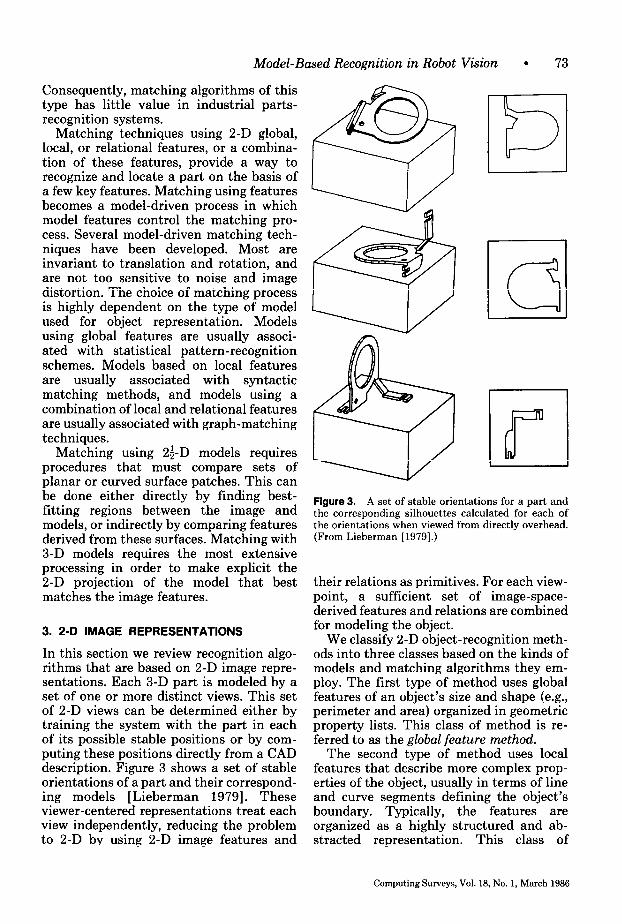
In this section we review recognition algo- rithms that are based on 2-D image repre- sentations. Each 3-D part is modeled by a set of one or more distinct views. This set of 2-D views can be determined either by training the system with the part in each of its possible stable positions or by com- puting these positions directly from a CAD description. Figure 3 shows a set of stable orientations of a part and their correspond- ing models [Lieberman 19791. These viewer-centered representations treat each view independently, reducing the problem to 2-D by using 2-D image features and
m
a
H Figure 3. A set of stable orientations for a part and the corresponding silhouettes calculated for each of the orientations when viewed from directly overhead. (From Lieberman [1979].)
their relations as primitives. For each view- point, a sufficient set of image-space- derived features and relations are combined for modeling the object.
We classify 2-D object-recognition meth- ods into three classes based on the kinds of models and matching algorithms they em- ploy. The first type of method uses global features of an object’s size and shape (e.g., perimeter and area) organized in geometric property lists. This class of method is re- ferred to as the global feature method.
The second type of method uses local features that describe more complex prop- erties of the object, usually in terms of line and curve segments defining the object’s boundary. Typically, the features are organized as a highly structured and ab- stracted representation. This class of
Computing Surveys, Vol. 18, No. 1, March 1986
74 l R. T. Chin and C. R. Dyer
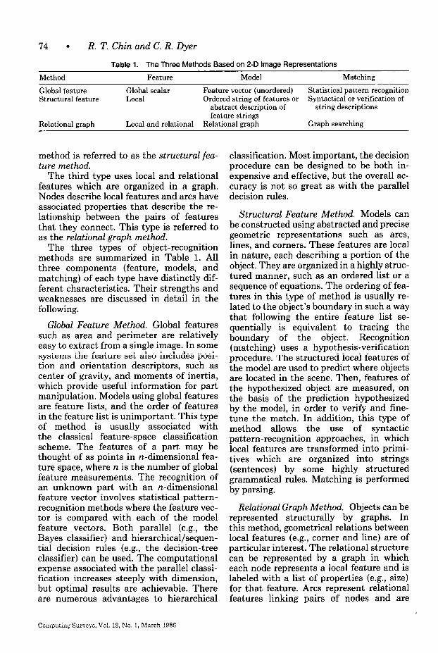
Table 1. The Three Methods Based on 2-D image Representations
Method Feature Model Matching
Global feature Structural feature
Relational graph
Global scalar Feature vector (unordered) Statistical pattern recognition Local Ordered string of features or Syntactical or verification of
abstract description of string descriptions feature strings
Local and relational Relational graph Graph searching
method is referred to as the structural fea- ture method.
The third type uses local and relational features which are organized in a graph. Nodes describe local features and arcs have associated properties that describe the re- lationship between the pairs of features that they connect. This type is referred to as the relational graph method.
The three types of object-recognition methods are summarized in Table 1. All three components (feature, models, and matching) of each type have distinctly dif- ferent characteristics. Their strengths and weaknesses are discussed in detail in the following.
Global Feature Method. Global features such as area and perimeter are relatively easy to extract from a single image. In some systems the feature set also includes posi- tion and orientation descriptors, such as center of gravity, and moments of inertia, which provide useful information for part manipulation. Models using global features are feature lists, and the order of features in the feature list is unimportant. This type of method is usually associated with the classical feature-space classification scheme. The features of a part may be thought of as points in n-dimensional fea- ture space, where n is the number of global feature measurements. The recognition of an unknown part with an n-dimensional feature vector involves statistical pattern- recognition methods where the feature vec- tor is compared with each of the model feature vectors. Both parallel (e.g., the Bayes classifier) and hierarchical/sequen- tial decision rules (e.g., the decision-tree classifier) can be used. The computational expense associated with the parallel classi- fication increases steeply with dimension, but optimal results are achievable. There are numerous advantages to hierarchical
Computing Surveys, Vol. 18, No. 1, March 1986
classification. Most important, the decision procedure can be designed to be both in- expensive and effective, but the overall ac- curacy is not so great as with the parallel decision rules.
Structural Feature Method. Models can be constructed using abstracted and precise geometric representations such as arcs, lines, and corners. These features are local in nature, each describing a portion of the object. They are organized in a highly struc- tured manner, such as an ordered list or a sequence of equations. The ordering of fea- tures in this type of method is usually re- lated to the object’s boundary in such a way that following the entire feature list se- quentially is equivalent to tracing the boundary of the object. Recognition (matching) uses a hypothesis-verification procedure. The structured local features of the model are used to predict where objects are located in the scene. Then, features of the hypothesized object are measured, on the basis of the prediction hypothesized by the model, in order to verify and fine- tune the match. In addition, this type of method allows the use of syntactic pattern-recognition approaches, in which local features are transformed into primi- tives which are organized into strings (sentences) by some highly structured grammatical rules. Matching is performed by parsing.
Relational Graph Method. Objects can be represented structurally by graphs. In this method, geometrical relations between local features (e.g., corner and line) are of particular interest. The relational structure can be represented by a graph in which each node represents a local feature and is labeled with a list of properties (e.g., size) for that feature. Arcs represent relational features linking pairs of nodes and are
Model-Based Recognition in Robot Vision l 75
labeled with lists of relation values (e.g., distance and adjacency). Recognition of the object becomes a graph-matching process. This type of method can be used to handle overlapping parts where a partially visible part corresponds to a subgraph. The match- ing reduces to one of finding the subgraph.
The remainder of this section covers ex- amples of each of these three methods in detail.
3.1 Examples of Global Feature Methods
The predominant method to date, espe- cially in commercial systems, uses a set of 2-D, global shape features describing each possible stable object view. Recognition is achieved by directly comparing features of an object with those of the model. This type of model is compact and facilitates fast matching operations because of the limited number and size of the feature vectors ex- tracted from a given image.
The major limitations of this type of model are (1) each possible 2-D view of an object must be described by a separate model; (2) all objects in an image must be extracted by a single predefined threshold (hence lighting, shadows, and highlights must be controlled); and (3) objects may not touch or overlap one another, nor may objects have significant defects. (A defec- tive object that is not sufficiently similar to any model can be recognized as a reject, but this may not be adequate in many applications.)
3.1.1 Example 1: A System Based on Connected Components
Model. The SRI Vision Module [Gleason and Agin 19791 is the prototypical system of the global feature method. The user in- teractively selects a set of global features which are used to construct an object model as a feature vector. This process is an ex- ample of the “training by showing” method of modeling. For each distinct viewpoint of each object modeled, a sample prototype is used to compute the values of each feature selected. The selection of which features are sufficient to discriminate adequately among objects is determined by trial and error. Thus, if a new object is introduced
later into the system, the complete process of feature selection must be repeated in order to discriminate properly among all of the possible objects in a scene.
Features. Each connected component in the input binary image is extracted so that each of these regions can be analyzed independently. For each connected com- ponent a number of gross scalar shape de- scriptors are computed (such as number of holes, area, perimeter, boundary chain code, compactness, number of corners, and moments of inertia). All of these features can be computed in a single pass through the image, either from the binary image representation or from the image’s run- length encoded representation (which is more compact).
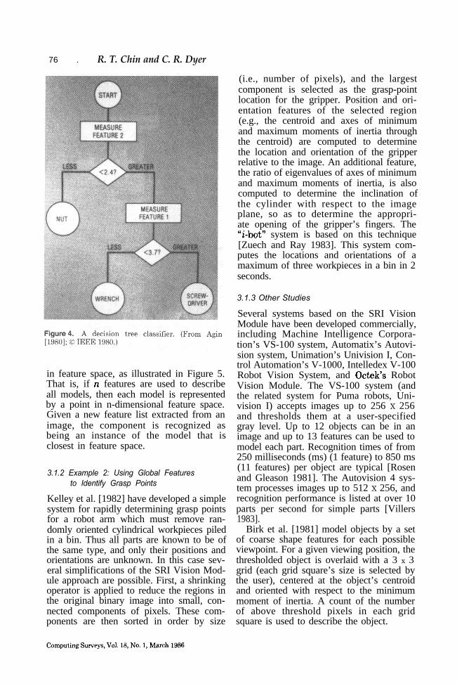
Matching. Matching uses a decision-tree method based on the list of global features associated with each model [Agin and Duda 19751. The tree is automatically con- structed from the models as follows. (1) The feature values with the largest sepa- ration for a given feature and pair of object models are found, and this feature is used to define the root node of the tree. That is, a threshold is selected for this feature that distinguishes between these two models. (2) Two children of the root node are con- structed such that all models that have a feature value less than or equal to the threshold are associated with the left child; the right child is assigned all models with a feature value greater than the threshold. (3) This procedure is repeated recursively, dividing a set of model candidates associ- ated with a node into two disjoint subsets associated with its two children. A terminal node in the tree is one that contains a single model. Figure 4 illustrates such a decision tree.
The decision-tree method has the pri- mary advantage of speed, but it also has the disadvantage of not allowing similar models to be explicitly compared with a given list of image features.
Alternatively, the best matching model to a given list of global features extracted from an object in an image is computed using statistical pattern-recognition schemes (e.g., a nearest-neighbor classifier)
Computing Surveys, Vol. 18, No. 1, March 1986
76 . R. T. Chin and C. R. Dyer
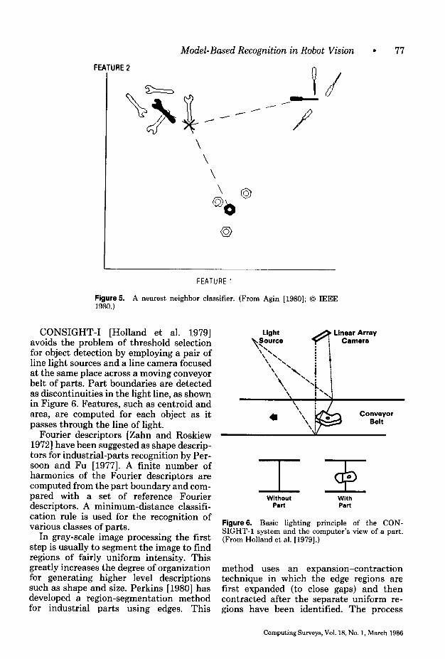
in feature space, as illustrated in Figure 5.That is, if n features are used to describeall models, then each model is representedby a point in n-dimensional feature space.Given a new feature list extracted from animage, the component is recognized asbeing an instance of the model that isclosest in feature space.
3.1.2 Example 2: Using Global Featuresto Identify Grasp Points
Kelley et al. [1982] have developed a simplesystem for rapidly determining grasp pointsfor a robot arm which must remove ran-domly oriented cylindrical workpieces piledin a bin. Thus all parts are known to be ofthe same type, and only their positions andorientations are unknown. In this case sev-eral simplifications of the SRI Vision Mod-ule approach are possible. First, a shrinkingoperator is applied to reduce the regions inthe original binary image into small, con-nected components of pixels. These com-ponents are then sorted in order by size
(i.e., number of pixels), and the largestcomponent is selected as the grasp-pointlocation for the gripper. Position and ori-entation features of the selected region(e.g., the centroid and axes of minimumand maximum moments of inertia throughthe centroid) are computed to determinethe location and orientation of the gripperrelative to the image. An additional feature,the ratio of eigenvalues of axes of minimumand maximum moments of inertia, is alsocomputed to determine the inclination ofthe cylinder with respect to the imageplane, so as to determine the appropri-ate opening of the gripper’s fingers. The“i-hot” system is based on this technique[Zuech and Ray 1983]. This system com-putes the locations and orientations of amaximum of three workpieces in a bin in 2seconds.
3.1.3 Other Studies
Several systems based on the SRI VisionModule have been developed commercially,including Machine Intelligence Corpora-tion’s VS-100 system, Automatix’s Autovi-sion system, Unimation’s Univision I, Con-trol Automation’s V-1000, Intelledex V-100Robot Vision System, and Octek’s RobotVision Module. The VS-100 system (andthe related system for Puma robots, Uni-vision I) accepts images up to 256 X 256and thresholds them at a user-specifiedgray level. Up to 12 objects can be in animage and up to 13 features can be used tomodel each part. Recognition times of from250 milliseconds (ms) (1 feature) to 850 ms(11 features) per object are typical [Rosenand Gleason 1981]. The Autovision 4 sys-tem processes images up to 512 X 256, andrecognition performance is listed at over 10parts per second for simple parts [Villers1983].
Birk et al. [1981] model objects by a setof coarse shape features for each possibleviewpoint. For a given viewing position, thethresholded object is overlaid with a 3 x 3grid (each grid square’s size is selected bythe user), centered at the object’s centroidand oriented with respect to the minimummoment of inertia. A count of the numberof above threshold pixels in each gridsquare is used to describe the object.
Model-Based Recognition in Robot Vision l 77
FEATURE 2
FEATURE1
Figure5. A nearest neighbor classifier. (From Agin [1980]; 0 IEEE 1980.)
CONSIGHT-I [Holland et al. 19791 avoids the problem of threshold selection for object detection by employing a pair of line light sources and a line camera focused at the same place across a moving conveyor belt of parts. Part boundaries are detected as discontinuities in the light line, as shown in Figure 6. Features, such as centroid and area, are computed for each object as it passes through the line of light.
\ : ,
Conveyor Belt
Fourier descriptors [Zahn and Roskiew 19721 have been suggested as shape descrip- tors for industrial-parts recognition by Per- soon and FU [1977]. A finite number of harmonics of the Fourier descriptors are computed from the part boundary and com- pared with a set of reference Fourier descriptors. A minimum-distance classifi- cation rule is used for the recognition of various classes of parts.
Without Pall
With PaIt
In gray-scale image processing the first step is usually to segment the image to find regions of fairly uniform intensity. This greatly increases the degree of organization for generating higher level descriptions such as shape and size. Perkins [1980] has developed a region-segmentation method for industrial parts using edges. This
Figure6. Basic lighting principle of the CON- SIGHT-l system and the computer’s view of a part. (From Holland et al. [1979].)
method uses an expansion-contraction technique in which the edge regions are first expanded (to close gaps) and then contracted after the separate uniform re- gions have been identified. The process
Computing Surveys, Vol. 18, No. 1, March 1986
78 . R. T. Chin and C. R. Dyer
is performed iteratively to preserve small segments.
An industrial-vision system, S.A.M., has been developed by Tropf et al. [ 19821, using binary image processing to extract global scalar features for inspection and parts rec- ognition. The system is now commercially available for flexible manufacturing assem- bly systems [Brune and Bitter 19831. A development system for machine vision based on the Machine Intelligence Corp. VS-100 has been developed and marketed [Chen and Milgram 19821. The perform- ance of the above vision system has also been evaluated by Rosen and Gleason [1981].
An experimental system has been devel- oped by Page and Pugh [1981] to manip- ulate engineering parts from random orientation. Simple global scalar features are used to identify gripper locations. Typical recognition times are in the range 0.5-3 seconds.
3.2 Examples of Structural Feature Methods
The system described in the previous sec- tion included global shape and size fea- tures, which consisted, for the most part, of simple integral or real-valued descrip- tors. In this section we describe methods that use more complex features, for the most part structural descriptions of object boundaries.
3.2.1 Example 1: Line and Arc Boundary Segment Descriptions
Model. Perkins [1978] constructs 2-D models from boundary segments, called concurves, constructed from line segments and arcs that are extracted from training images of each stable view of each part. The list of concurves comprises a structural ap- proach to describing objects that is not as sensitive to noise as most global features.
The model uses an object-centered coor- dinate system in which the origin is defined by either (a) the center of area of the largest closed concurve or (b) the center of a small closed concurve if it is sufficiently close to the center of the largest closed concurve. The axes are defined in terms of the direc-
tion of the least moment of inertia of the largest concurve.
For each concurve in the model a prop- erty list is computed, including type (circle, arc, line segment, complex curve, etc.), total length or radius of arcs, magnitude of total angular change, number of straight lines, number of arcs, bending energy, and com- pactness. In addition, rotational symme- tries of the concurve and the complete object are computed as additional descrip- tors. Rotational symmetry is computed using a correlation-like technique which determines whether a sufficient percentage of concurve “multisectors” intersects the rotated concurve. Multisectors are short line segments that are placed at equal in- tervals along the concurve and at orien- tations perpendicular to the tangent directions at these points.
Features. Concurve features are used in order to represent the 2-D shape of a part as a line drawing of its boundary. This representation is compact and, because the boundary is smoothed before the concurves are computed, relatively insensitive to noise in the imaging system and environ- ment. First, a gray-scale image is trans- formed into an edge map using the Hueckel edge operator [Hueckel 19711. Next, edge points are thinned and connected together into long chains by using knowledge of proximity, directional continuity, and gray- scale continuity.
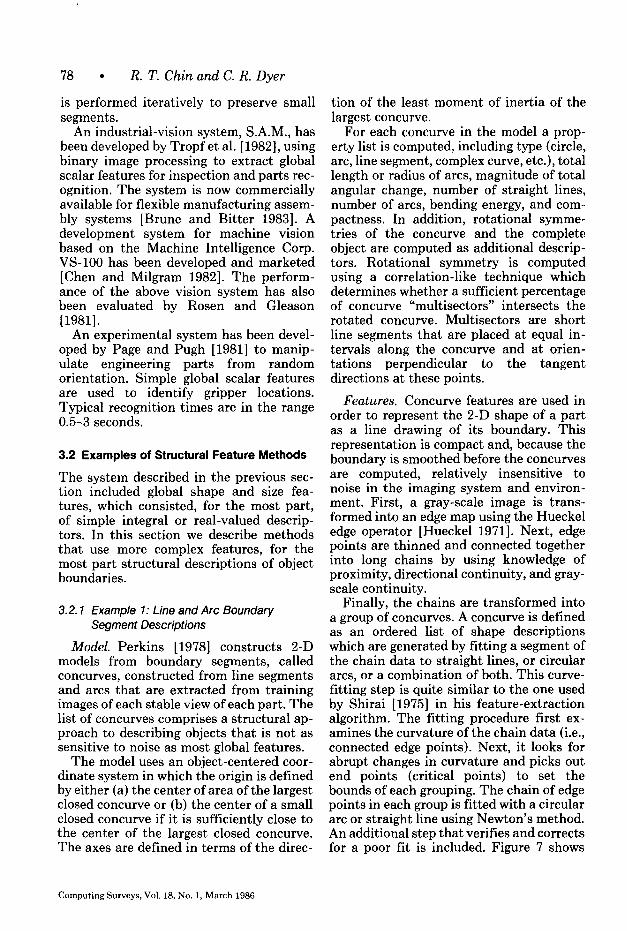
Finally, the chains are transformed into a group of concurves. A concurve is defined as an ordered list of shape descriptions which are generated by fitting a segment of the chain data to straight lines, or circular arcs, or a combination of both. This curve- fitting step is quite similar to the one used by Shirai [1975] in his feature-extraction algorithm. The fitting procedure first ex- amines the curvature of the chain data (i.e., connected edge points). Next, it looks for abrupt changes in curvature and picks out end points (critical points) to set the bounds of each grouping. The chain of edge points in each group is fitted with a circular arc or straight line using Newton’s method. An additional step that verities and corrects for a poor fit is included. Figure 7 shows
Computing Surveys, Vol. 18, No. 1, March 1986
Model-Based Recognition in Robot Vision 79
(b)
Cc) (d)
Figure 7. Concurve representation. (a) Digitized image. (b) Edge points. (c) Chains withcritical points at the ends of open chains. (d) Concurves. (From Perkins [1978]; 0 IEEE 1978.)
the various stages of extracting concurvesfrom a sample image.
Matching. The matching process is per-formed in three steps. First, scalar mea-surements (length, area, etc.) extractedfrom the model and image concurves arecompared. The comparison is an exhaustivematching procedure applied to all possiblepairings between the model concurves andthe image concurves, and the results, givenin terms of likelihood measures, are ar-ranged in an ordered list. Second, onemodel concurve is matched against oneimage concurve to determine a tentativetransformation (x, y, 8) from model to im-
age coordinates. The pair with the highestlikelihood is used first; successive pairs arecompared until a tentative transformationis found. In cases in which the model con-curve is symmetric, two matching pairs arerequired to determine the transformation.Third, a global check of the tentative trans-formation is performed by matching thecomplete model with the image. In this stepa set of model multisectors is first trans-formed using the tentative transformationdetermined in the previous step. The trans-formed multisectors of the model are thensuperimposed on the image for a final com-parison by intersecting each multisectorwith the image concurves. This matching
80 . R. T. Chin and C. R. Dyer
process is shown to be successful with pied by the object. Finally, the other lines closed concurves and has been tested with of the object are located to confirm the images containing partially overlapping recognition. parts.
3.2.2 Example 2: Hierarchical Boundary Segment Models
3.2.3 Example 3: Accumulating Local Evidence by Clustering Pairs of Image and Model Boundary Segments
Model. In the system developed by Shi- rai [1978], object models are organized as a hierarchy of features consisting of main and secondary features. These features are edges represented by a description of their curvature in terms of an equation and end- points. The main feature is the most ob- vious one found in an object, and it is used to imply the presence of the object during the initial stage of the search. Successful detection of the main feature generates clues for verifying the recognition. Second- ary features are details of the object. These are chosen on the basis of the ease with which they may be found in a scene. For recognizing a cup, for example, the main feature can be a pair of vertical edges cor- responding to the sides of a cup, and the secondary features can be other detail con- tours connected to the sides.
Model. Stockman et al. [1982] have pro- posed a method in which models of 2-D objects are defined by organizing (1) real vectors describing boundary segments and (2) abstract vectors linking primitive fea- tures (e.g., a vector connecting two holes) into a set. The set is in an object-centered coordinate system and is defined by mod- eling rules (e.g., size of the object, known a priori) to permit only certain combinations of features to be linked. The resulting model is a line-drawing version of the ob- ject, plus additional abstract vectors to al- low increased precision and control over the matching process.
Features. The features used by Shirai are similar to those used by Perkins, con- sisting of long, connected edge segments that describe pieces of an object’s bound- ary. The system first extracts edges using a conventional gradient operator. The ex- tracted edges are classified into three types according to their intensity profiles. Next, an edge kernel is located by searching for a set of edge points of the same type which have similar gradient directions. A tracking algorithm is applied in both directions of the kernel to find a smoothly curved edge and its endpoints. Several passes are ap- plied to locate all sets of smoothly con- nected edges in the scene. Finally, straight lines and elliptic curves are fit to each segment, and segments are merged to- gether, if possible.
Features. Directed edge elements (vec- tors) are used as one type of primary feature containing directional, positional, and size information. First, point features (i.e., the tip and tail of a vector) are extracted, and then vectors are formed from suitable point pairs. Straight edge detectors, curved edge detectors, circle detectors, and intersection detectors are employed to define vectors between point pairs. Holes are detected by a set of circular masks, and curves and intersections are detected by linking edges together. Details of the feature-extraction procedure are presented in Stockman [ 19801.
Matching. Recognition involves three steps. First, the main feature is located to get clues for the object. Next, a secondary feature is searched for to verify the main feature and to determine the region occu-
Matching. Matching is done using a clustering procedure. The procedure matches all possible pairs of image and model features on the basis of local evi- dence, The matching in cluster space con- sists of points, each representing a match of an image feature to a model feature. A cluster of match points in this space is a good indication that many image features are matched to corresponding model fea- tures. In order to handle randomly placed objects, a rotation, scaling, and translation transformation is derived to extract param- eters from all possible pairs of features.
Computing Surveys, Vol. 18, No. 1, March 1986
Model-Based Recognition in Robot Vision l 81
Clustering is then performed in the space of all possible transformation parameter sets. This method is believed to be more robust because the clustering procedure in- tegrates all local information before any recognition decision is made. A set of sim- ulated carburetor covers and T-hinges are used to demonstrate the method. The re- ported results indicate that this method works well with isolated objects, l%rt the success rate for recognizing overlapping parts is low.
3.2.4 Other Studies
Hattich [1982] uses contour elements, de- scribed in terms of straight-line segments, as the global structural features. Matching is done by iteratively constructing the model contour from image data.
Experiments on occluded part recogni- tion have been performed by Turney et al. [1985] using edges as the features. Recog- nition is based on template matching be- tween the model edge template and the edge image in the generalized Hough transform space [Ballard 1981a]. This algorithm is shown to be more efficient than direct tem- plate matching. Dessimoz [1978a, 1978b] recognizes overlapping parts by first map- ping the objects’ boundaries into a set of curves and then matching the curves with those in the model. Tropf [1980,1981] has developed a recognition system for overlap- ping workpieces using corner and line prim- itives and semantic labeling. Structural knowledge of workpieces is used to con- struct models. Recognition uses heuristic search to find the best match based on a similarity measure. Ayache [1983] uses bi- nary images and polygonal approximations to each connected component. Models are automatically constructed by analyzing a prototype part in its different stable posi- tions. The matching is done first by gen- erating a hypothesis of the object location and then by matching model segments to scene segments. The model location is se- quentially adjusted by evaluating each match until the best match is found.
Bhanu has developed a hierarchical re- laxation labeling technique for shape matching and has performed experiments
using 2-D occluded industrial parts [Bhanu 1983; Bhanu and Faugeras 19841. Two- dimensional shapes are used as the global structural features, and they are repre- sented by a polygonal approximation. The technique involves the maximization of an evaluation function which is based on the ambiguity and inconsistency of classifi- cation. Umetani and Taguchi [1979] use “general shapes,” defined as artificial and nonartificial shapes, to study the prop- erties and procedures for complex shape discrimination. Feature properties based on vertices, symmetry, complexity, com- pactness, and concavity have been in- vestigated. These features are chosen on the basis of some psychological experi- ments, and a procedure to discriminate random shapes has been proposed [Umetani and Taguchi 19821.
Vamos [1977] has proposed the use of syntactic pattern recognition for modeling machine parts from picture primitives: namely, straight line, arc, node, and unde- fined. A set of syntax rules is used to characterize the structural relationships of these strings of primitives describing the part. The matching process is a syntax analysis or parsing procedure involving the use of similarity measures between two grammar strings or two graphs. Jakubowski has conducted a similar study using straight lines or curves as primitives to model machine part shapes and to generate part contours [Jakubowski 1982; Jakubowski and Kasprzak 19771.
Takeyasu et al. [1977] and Kashioka et al. [1977] have developed an assembly sys- tem for vacuum cleaners using integrated visual and tactile sensory feedback. First, global scalar features of various parts of the vacuum cleaner are used to locate the cleaner. Then, structural features, such as circles and arcs, are used in a template- matching step for the assembly operation.
Foith et al. [1981] describe an object boundary with respect to the centroid of the “dominant blob” defining the 2-D binary object. Circles of prespecified radii are centered on the centroid, their intersec- tions with the object boundary are marked, and line segments are then drawn between these intersections and the centroid. The
Computing Surveys, Vol. 18, No. 1, March 1986
82 ’ R. T. Chin and C. R. Dyer
sequence of angles between successive line segments is used as a rotation-invariant model of the object boundary.
3.3 Examples of Relational Graph Methods
This class of methods is based on a graph representation of a part. The graph is con- structed in terms of locally detectable prim- itive features and the geometric relations between pairs of these features. This class of method is thus based on local rather than global features and has the following advantages: (a) local features may be cheaper to compute because they are sim- pler and can be selectively (sequentially) detected; (b) models are less sensitive to minor differences in instances of a given object type; (c) if a few local features are missing (owing to noise or occlusion), it may still be possible to recognize the object on the basis of the remaining features as- sociated with the model; and (d) since a few types of local features are often sufficient to describe a large number of complex ob- jects, it is possible to specify only a few types of local feature detectors which are applied to the image.
A disadvantage with this type of method is the fact that a large number of features must be detected and grouped together to recognize an object. Thus the matching al- gorithm used with these models must be more complex and may be somewhat slower than the matching algorithms used with the previous methods.
3.3.1 Example 1: A Two-Level Model of Coarse and Fine Features
Model. Yachida and Tsuji [1977] use a simple kind of feature graph representation plus a two-level model (for coarse-to-fine processing) to speed the search process. Each object is described by a set of models, one for each possible viewpoint. Each model contains a coarse representation of the object using global features, such as area and elongatedness, plus a description of the outer boundary (in polar coordi- nates). Each component extracted from an image is compared with each coarse model to determine whether it is sufficiently sim- ilar to warrant further comparison. Object
boundaries are compared by using cross- correlation as the measure of shape match.
The fine level of representation of each model is based on a higher resolution image and consists of a list of features such as outer boundary, holes, edges, and texture. Associated with each feature is an attribute list, location (relative to the object’s cen- troid), and the expected likelihood that the feature! can be extracted reliably. Features are ordered in the model by their reliability value.
Features. The feature-extraction process in this system is divided into several stages by using the idea of “planning”; that is, knowledge of the structure of an object guides the feature-extraction module in a top-down manner. Simple features are de- tected first in a coarse resolution image, and then more complex features are sought on the basis of the locations of the coarse features. Industrial parts used for demon- stration are parts of a gasoline engine. In the preprocessing stage, a low-resolution version of the image is analyzed and outlines of objects are detected by thresh- olding. Each outline is then analyzed sep- arately, using a high-resolution image of the region of interest to extract a finer outline of the object. By employing the method in Chow and Kaneko [1972], local histogramming and dynamic thresholding based on 11 x 11 windows are used in this step. Next, the object’s gross properties, such as size, thinness ratio, and shape, are computed. This coarse description of the object is used to select candidate models for matching and to guide the extraction of finer features for final recognition. There are four features extracted in the fine- resolution processing stage, and they in- clude circle, line, texture, and small hole. Each feature is extracted from a search region around the expected location in the gray-scale image. The circle detector uses thresholding as in the preprocessing step; the line finder, using dynamic program- ming, searches for the optimum sequence of edge points in the region that maximizes a measure of goodness; the texture detector measures edge strength per unit area and average edge direction; the small-hole
Computing Surveys, Vol. 18, No. 1, March 1986
Model-Based Recognition in Robot Vision l 83
detector uses neighbor merging to locate circular objects.
Matching. The matching process exam- ines the current information obtained from the scene and the model graphs of objects to propose the next matching step. The model relates features at a coarse resolution with more detailed features at a fine reso- lution, enabling the matching to be per- formed using simple features as cues. Given a tentative match between an image com- ponent and an object model based on the coarse model features, the fine model fea- tures are then successively compared. The object boundary matched at the coarse level determines a tentative match angle of ro- tation. For a given feature extracted from the image, a measure of the dissimilarity between it and each of the model features is computed. A cumulative dissimilarity measure is kept for each active model. When a model’s dissimilarity exceeds a threshold, the model is rejected as a possi- ble match. After the current feature has been compared with each of the remaining candidate models, a next-feature proposer analyzes the features described in these candidate models and proposes the most promising feature among them as the one to be examined next for recognizing the input object.
3.3.2 Example 2: Corner and Hole Relational Models
Model. Chen et al. [1980] estimate the position and orientation of workpieces using the 3-D locations of at least three noncollinear feature points. The location of features is computed using trigonometric relations between corresponding features from two stereo views of the workpiece. The model is in the form of a local feature graph. Each node is a (feature-type, position) pair, and arcs connect pairs of nodes when an edge connects the pair of features on the part. Feature types are corners and small holes. Feature position is specified using an object-centered coordinate system.
Features. Local image features include small holes and corners. Corner and small hole detection is based on diameter-limited
gradient direction histograms [Birk et al. 19791 in which intensity variations in sev- eral directions and various heuristic thresh- olds are examined. Detected features from the image are evaluated to eliminate redun- dant features. The resultant corner points are fine-tuned for accuracy by fitting a pair of lines in an 11 x 11 window. The inter- section of the two lines yields the final corner location. Finally, the interfeature distances between every pair of features are computed. Workpiece examples used in the experiments include simple planar indus- trial parts and 3-D block objects.
Matching. The matching is carried out by a sequential pairwise comparison algo- rithm in which a feature point is matched in turn to all model feature points of the same type. The matching process starts with the selection of the feature point that has the highest confidence. The remaining feature points are then matched with all model points. In this step feature type, interfeature distance, and edge information are used as matching criteria, and redun- dant matched points are deleted. If enough feature points are successfully matched with the model points, and a transforma- tion test, used to eliminate problems due to symmetry, is passed, a match is considered to be found. Finally, the position and ori- entation of the workpiece are computed from the correspondence between work- piece and model features.
3.3.3 Example 3: Combining Model Graphs Based on Distinctive Focus Features
Model. Bolles and Cain [1982] have de- veloped a sophisticated modeling system for 2-D objects called the local-feature- focus method. Two types of local features are used: corners and regions. An object model consists of three parts. The first is a polygonal approximation of the object’s borders. The second is a list of local fea- tures, where each is specified by a unique name, its type, position, and orientation relative to the object’s centroid, and rota- tional symmetries about the centroid. Position and orientation values also have associated allowable tolerances. Third, for each distinct feature type, an unambiguous
Computing Surveys, Vol. 18, No. 1, March 1986
84 . R. T. Chin and C. R. Dyer
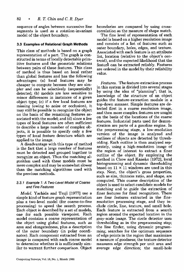
Figure 8. An example of a focus feature on a hinge. Nearby features found around a hole and their lists of possible model features. (From Bolles and Cain [1982].)
description of each possible instance of this feature type in all the models is determined. In this way each possible feature type can be used as a “focus feature.” Each structur- ally different occurrence of a given feature type has an associated feature-centered subgraph description containing a suffi- cient set of “secondary” features (and their relative locations) to uniquely identify the given focus feature and determine the po- sition and orientation of the object.
Features. A semiautomatic procedure is currently used to construct these focus fea- ture tables. First, all possible distinguish- able local feature types are determined over all stable viewpoints of all objects. The extraction of features is automatically per- formed by analysis of computer-aided design (CAD) models of the objects. Next, rotational and mirror symmetries are de- termined in order to identify all structurally equivalent features. For each structurally different feature, select a set of nearby features that uniquely identifies the focus feature and construct a graph description of these features and their relations. Fea- ture types are ranked by the size of their associated feature graphs (i.e., in increasing order of the sum of the number of second- ary features needed to describe all instances of the given focus feature).
Computing Surveys, Vol. 18, No. 1, March 1986
In extracting key features, the system locates holes by finding small regions in the binary image and extracts corners by mov- ing a jointed pair of chords around the boundaries and comparing the angle be- tween the chords with the angles defining the different types of corners. This corner finder is believed to have difficulties with rounded corners. Relational features, such as distances between features, are used to describe position and orientation of objects. Another set of useful features used in this system is the symmetries of the object. Both the rotational and mirror symmetries of binary patterns are extracted automati- cally, using the method in Bolles [1979a]. These symmetries are useful in the reduc- tion of the number of features to be consid- ered, since symmetrical objects usually have duplicate features.
Matching. The matching procedure of the local-feature-focus method uses a graph-matching technique to identify the largest cluster of image features matching a cluster of model features [Bolles 1976b]. The procedure first retrieves models of in- dustrial parts, together with the list of focus features and their nearby features. Figure 8 shows an example of a focus feature. Then, for each image, the system locates all the potentially useful local features,
Model-Based Recognition in Robot Vision -
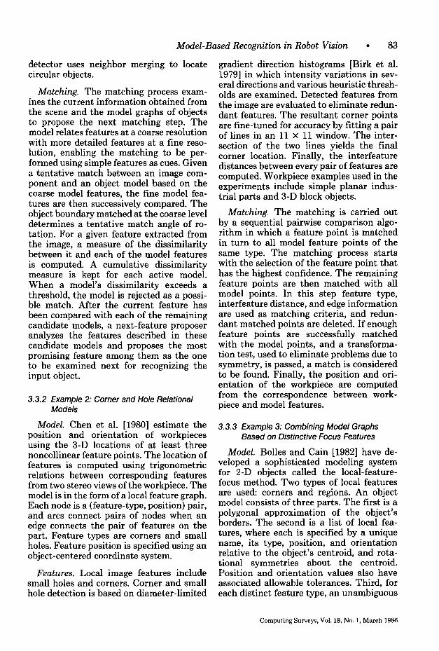
Figure 9. (a) Definitions of the model features of the hinge. (h) List of model-feature-to-image-feature assignments. (c) Graph of painvise-consistent assignments. Each node rep-resents a possible assignment of a model feature to an image feature. Two nodes areconnected if the two assignments they represent are mutually consistent. (From Belles andCain [1982].)
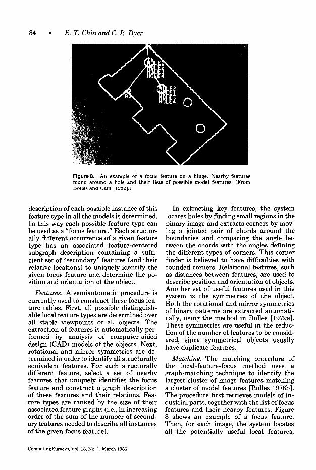
Figure 10. Image of five hinges and the recognition result. (From Belles and Cain [1982].)
forms clusters of them to hypothesize partoccurrences, and finally performs templatematches to verify these hypotheses.
After locating all the features found inthe image, the system selects one feature(the focus feature) around which it tries tofind a cluster of consistent secondary fea-tures. If this attempt fails to lead to ahypothesis, the system seeks another po-tential focus feature for a new attempt. Asit finds matching features, it builds a listof possible model-feature-to-image-featureassignments. This list is transformed intoa graph by creating a node for each assign-ment pair and adding an arc between pairs
of nodes referencing the same model; Fig-ure 9 shows the possible assignments andthe resulting graph. The result from thefirst stage of the matching algorithm is usedto hypothesize an object. At the final stage,two tests are used to verify the hypothesesby looking at other object features andchecking the boundary of the hypothesizedobject. Figure 10 shows an example.
3.3.4 Example 4: Template Feature Relations
Models. An automatic system for tran-sistor wire bonding has been implementedby Kashioka et al. [1976]. The model
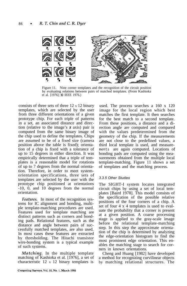
86 - R. T. Chin and C. R. Dyer
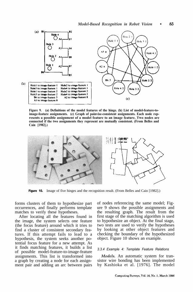
Figure 11. Nine corner templates and the recognition of the circuit positionby evaluating relations between pairs of matched templates. (From Kashiokaet al. [1976]; 0 IEEE 1976.)
consists of three sets of three 12 x 12 binarytemplates, which are selected by the userfrom three different orientations of a givenprototype chip. For each triple of patternsin a set, an associated distance and direc-tion (relative to the image’s z axis) pair iscomputed from the same binary image ofthe chip used to define the templates. Chipsare assumed to be of a fixed size (cameraposition above the table is fixed); orienta-tion of a chip is fixed with a tolerance ofup to 15 degrees in either direction. It wasempirically determined that a triple of tem-plates is a reasonable model for rotationsof up to 7 degrees from the normal orienta-tion. Therefore, in order to meet system-orientation specifications, three sets oftemplates are selected by the user with theprototype chip positioned at orientations-10, 0, and 10 degrees from the normalorientation.
Features. In most of the recognition sys-tems for IC alignment and bonding, multi-ple template-matching procedures are used.Features used for template matching aredistinct patterns such as corners and bond-ing pads. Relational features, such as thedistance and angle between pairs of suc-cessfully matched templates, are also used.In most cases these features are extractedby thresholding. The Hitachi transistorwire-bonding system is a typical exampleof such systems.
Matching. In the multiple templatematching of Kashioka et al. [1976], a set ofcharacteristic 12 x 12 binary templates is
used. The process searches a 160 x 120image for the local region which bestmatches the first template. It then searchesfor the best match to a second template.From these positions, a distance and a di-rection angle are computed and comparedwith the values predetermined from thegeometry of the chip. If the measurementsare not close to the predefined values, athird local template is used, and measure-ments are again computed. Locations ofbonding pads are computed using the mea-surements obtained from the multiple localtemplate-matching. Figure 11 shows a setof templates and the matching process.
3.3.5 Other Studies
The SIGHT-I system locates integratedcircuit chips by using a set of local tem-plates [Baird 1978]. This model consists ofthe specification of the possible relativepositions of the four corners of a chip. Aset of four 4 x 4 templates is used to eval-uate the probability that a corner is presentat a given position. A coarse processingstage is applied to the gray-scale imagebefore the relational template-matchingstep. In this step the approximate orienta-tion of the chip is determined by analyzingthe edge-orientation histogram to find themost prominent edge orientation. This en-ables the matching stage to search for cor-ners in known orientations.
Cheng and Huang [1982] have developeda method for recognizing curvilinear objectsby matching relational structures. The
Model-Based Recognition in Robot Vision l 87
boundary of an object is segmented into curve segments and then into chords. At- tributes (parallel, symmetric, adjacent, etc.) associated with the chords are used as the nodes in the relational structure represen- tation of the object. Matching is based on a star structure representation of the object [Cheng and Huang 19811. The recognition of overlapping tools has been shown.
Segen [1983] has developed a method for recognizing partially visible parts by using local features computed from an object boundary. The local features used are de- fined at points of local maximum and min- imum of contour curvature. A local feature from the image is matched with a feature from the model, and they determine a transformation (rotation and translation). All features are used in the matching, and a set of transformations is generated. The algorithm then clusters together features that imply similar transformations. The center of each cluster is used to define a candidate transformation that may possi- bly give a partial match. Finally, these can- didate transformations are tested with a point-by-point matching of the image con- tour and the transformed model contour.
Westinghouse’s gray-level robot vision system uses a simple form of the relational feature graph approach. In one of the re- ported studies [Schachter 19831, edges are used to form corners where a corner is defined as two intersecting edge vectors. The matching algorithm searches for four edge vectors forming two opposing corners such that the center of the line segment joining the corner pair coincides with the part center. The assumption that the object center and the two opposing corners are collinear restricts the applicability of the algorithm to limited types of industrial parts.
In semiconductor chip manufacturing, each die is visually inspected for the bond- ing of the die onto the package substrate and the bonding of wires from the die pads to the physically larger package leads. The process involves the recognition of the chip boundary, the determination of the chip position and orientation, and the recogni- tion of bonding pads. Conventionally, hu- man operators have to perform all of these functions. Recently, a number of automatic
die-bonding and wire-bonding systems have been developed for the manufacturing of chips. Most of these systems are based on relational features and associated matching algorithms. Some other IC rec- ognition systems include those of Horn [1975a], Hsieh and FU [1979], Igarashi et al. [ 19791, and Mese et al. [1977].
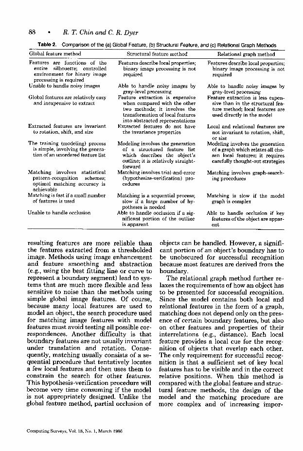
3.4 Comparison of the Three Methods for 2-D Object Representation
On the basis of the above descriptions of 2-D object-recognition algorithms, the fol- lowing general conclusions can be made about global feature, structural feature, and relational graph methods. A summary of this comparison is shown in Table 2.
Features used in the global feature method are easy to compute from binary images, and their ordering in the model is unimportant. This makes the training process a relatively simple task. Features can be computed in real-time from, for example, a run-length encoding of the im- age. This method also has the advantage that the features can often be simply de- fined to be shift and rotation invariant. That is, objects may be placed at any posi- tion and orientation, and the camera ge- ometry does not have to be fixed. In addi- tion, optimal matching accuracy can be achieved by using standard statistical pat- tern-recognition techniques. The main dis- advantage of global feature methods is the assumption that almost all of the objects must be visible in order to measure these features accurately. Thus, objects are not allowed to touch or overlap one another or contain defects. Unless the environment can be sufficiently controlled to eliminate these conditions, we are not likely to find global features because they are so large (e.g., due to occlusion).
The structural feature method is an im- provement over the global feature method in terms of capability and robustness, but its complexity requires more sophisticated training and matching processes. This makes it computationally more expensive. Local and extended boundary features are used to represent smoothed, intermediate- level symbolic descriptions. Since gray- level images are generally used, the
Computing Surveys, Vol. 18, No. 1, March 1966
88 l R. T. Chin and C. R. Dyer
Table 2. Comparison of the (a) Global Feature, (b) Structural Feature, and (c) Relational Graph Methods
Global feature method Structural feature method Relational granh method
Features are functions of the entire silhouette; controlled environment for binary image processing is required
Unable to handle noisy images
Global features are relatively easy and inexpensive to extract
Extracted features are invariant to rotation, shift, and size
The training (modeling) process is simple, involving the genera- tion of an unordered feature list
Matching involves statistical pattern-recognition schemes; optimal matching accuracy is achievable
Matching is fast if a small number of features is used
Unable to handle occlusion
Features describe local properties; binary image processing is not required
Able to handle noisy images by gray-level processing
Feature extraction is expensive when compared with the other two methods; it involves the transformation of local features into abstracted representations
Extracted features do not have the invariance properties
Modeling involves the generation of a structured feature list which describes the object’s outline; it is relatively straight- forward
Matching involves trial-and-error (hypothesize-verification) pro- cedures
Matching is a sequential process; slow if a large number of hy- potheses is needed
Able to handle occlusion if a sig- nificant portion of the outline is apparent
Features describe local properties; binary image processing is not required
Able to handle noisy images by gray-level processing
Feature extraction is less expen- sive than in the structural fea- ture method, local features are used directly in the model
Local and relational features are not invariant to rotation, shift, or size
Modeling involves the generation of a graph which relates all cho- sen local features; it requires carefully thought-out strategies
Matching involves graph-search- ing procedures
Matching is slow if the model graph is complex
Able to handle occlusion if key features of the object are appar- ent
resulting features are more reliable than the features extracted from a thresholded image. Methods using image enhancement and feature smoothing and abstraction (e.g., using the best fitting line or curve to represent a boundary segment) lead to sys- tems that are much more flexible and less sensitive to noise than the methods using simple global image features. Of course, because many local features are used to model an object, the search procedure used for matching image features with model features must avoid testing all possible cor- respondences. Another difficulty is that boundary features are not usually invariant under translation and rotation. Conse- quently, matching usually consists of a se- quential procedure that tentatively locates a few local features and then uses them to constrain the search for other features. This hypothesis-verification procedure will become very time consuming if the model is not appropriately designed. Unlike the global feature method, partial occlusion of
objects can be handled. However, a signifi- cant portion of an object’s boundary has to be unobscured for successful recognition because most features are derived from the boundary.
The relational graph method further re- laxes the requirements of how an object has to be presented for successful recognition. Since the model contains both local and relational features in the form of a graph, matching does not depend only on the pres- ence of certain boundary features, but also on other features and properties of their interrelations (e.g., distance). Each local feature provides a local cue for the recog- nition of objects that overlap each other. The only requirement for successful recog- nition is that a sufficient set of key local features has to be visible and in the correct relative positions. When this method is compared with the global feature and struc- tural feature methods, the design of the model and the matching procedure are more complex and of increasing impor-
Computing Surveys, Vol. 18, No. 1, March 1986
Model-Based Recognition in Robot Vision l 89
tance. The matching procedure involves graph-searching techniques that are com- putationally intensive and too slow with- out special-purpose hardware for many industrial applications. Hierarchical graph- searching techniques (e.g., Barrow and Tenenhaum [1981]) can reduce the time complexity of the matching process by decomposing the model into independent components.
4. 2&D SURFACE REPRESENTATIONS
The previous section presented methods based on image intensities, deriving fea- tures from gray-level or binary images to represent the projection of an object in two dimensions. In this section we present an- other class of methods, which is also viewer centered, but which is based on physical- scene characteristics of a single view of an object. This representation maintains in- formation in register with the original gray- scale image and includes intrinsic images [Barrow and Tenenbaum 19781, 2$0 sketch [Marr 19781, needle map [Horn 19791, parameter images [Ballard 1981b], and surface-orientation map [Brady 1982a]. Intrinsic scene parameters include surface range, orientation, discontinuities, reflec- tance, illumination, color, and velocity. Since this local information is obtained over a whole region within some bound- aries, it is more robust than the edge-based techniques used with many of the 2-D representations discussed in the previous section.
All of the methods in this section use scene surface properties derived from a sin- gle viewpoint to define features and con- struct models. If multiple views of an object are required, each is modeled indepen- dently. We have included range maps as part of this class of representation despite the fact that 3-D data are used. This is because the models that use these data are viewer centered and emphasize the descrip- tion of observable surface features from a single viewpoint. Models that describe a complete (viewpoint-insensitive) 3-D ob- ject are included in the next section as 3-D representations.
Most current research is focusing on the problem of how to compute these intrinsic surface maps. See, for example, Ballard and Brown [1982], Barrow and Tenenbaum [ 19781, Brady [1982a], Jarvis [1983a], and Marr [ 19821, for surveys of many applicable techniques. The present survey does not consider this “measurement” stage.
Of particular interest for applications in industrial-parts recognition is the compu- tation and use of range maps and local surface-orientation (needle) maps. Jarvis [1983a] and Poje and Delp [1982] give re- cent overviews of range-finding techniques using both active and passive methods. Ac- tive methods include ultrasonic and light time-of-flight measurement, and structured light projection using a plane or grid of light. Although early methods of these types have been slow, expensive, and of low accuracy, many recent improvements have been made [Agin and Highnam 1982; Al- tschuler et al. 1981; Jarvis 1983b; Kanade and Asada 1981; Pipitone and Marshall 1983; Popplestone et al. 19751.
Instead of extracting a range map, other researchers are focusing on obtaining local surface orientation as a descriptor of sur- face shape. This includes such direct meth- ods as shape from shading [Horn 1975b], shape from texture [Bajcsy 1973; Bajcsy and Lieberman 1976; Kender 1980; Stevens 1981; Witkin 19811, and shape from pho- tometric stereo [Woodham 19781.
One method of computing surface ori- entation that shows considerable promise for industrial-parts recognition is called photometric stereo [ Woodham 19781. Local surface orientation is computed using a re- flectance map for each of three different incident illumination directions, but from a single viewing direction. Since an object point corresponds to the same pixel in each of these three gray-level images, the surface orientation at this point can be obtained from the intersection of isobrightness con- tours in the reflectance maps associated with each light source. The method has been implemented very efficiently by in- verting the reflectance maps into a lookup table which gives surface orientation from a triple of gray levels [Silver 19801. So far
Computing Surveys, Vol. 18, No. 1, March 1986
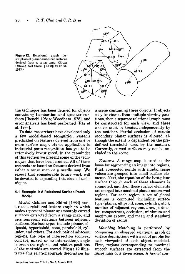
90 l R. T. Chin and C. R. Dyer
Figure 12. Relational graph de- scription of planar and curve surfaces derived from a range map. (From Oshima and Shirai [1983]; 0 IEEE 1983.)
the technique has been defined for objects containing Lambertian and specular sur- faces [Ikeuchi 1981a; Woodham 19781, and error analysis has been performed [Ray et al. 19831.
To date, researchers have developed only a few model-based recognition systems predicated on features derived from one or more surface maps. Hence application to industrial parts-recognition has yet to be extensively investigated. In the remainder of this section we present some of the tech- niques that have been studied. All of these methods are based on features derived from either a range map or a needle map. We expect that considerable future work will be devoted to expanding this class of tech- niques.
4.1 Example 1: A Relational Surface Patch Model
Model. Oshima and Shirai [1983] con- struct a relational-feature graph in which nodes represent planar or smoothly curved surfaces extracted from a range map, and arcs represent relations between adjacent surfaces. Surface types include planar, el- lipsoid, hyperboloid, cone, paraboloid, cyl- inder, and others. For each pair of adjacent regions, the type of intersection (convex, concave, mixed, or no intersection), angle between the regions, and relative positions of the centroids are stored. Figure I2 illus- trates this relational-graph description for
a scene containing three objects. If objects may be viewed from multiple viewing posi- tions, then a separate relational graph must be constructed for each view, and these models must be treated independently by the matcher. Partial occlusion of certain secondary planar surfaces is allowed, al- though the extent is dependent on the pre- defined thresholds used by the matcher. Currently, curved surfaces may not be oc- cluded in the scene.
Features. A range map is used as the basis for segmenting an image into regions. First, connected points with similar range values are grouped into small surface ele- ments. Next, the equation of the best plane surface through each of these elements is computed, and then these surface elements are merged into maximal planar and curved regions. For each region, a set of global features is computed, including surface type (planar, ellipsoid, cone, cylinder, etc.), number of adjacent regions, area, perime- ter, compactness, occlusion, minimum and maximum extent, and mean and standard deviation of radius.
Matching. Matching is performed by comparing an observed relational graph of surface descriptions with a set of graphs for each viewpoint of each object modeled. First, regions corresponding to maximal smooth surfaces are extracted from the range map of a given scene. A kernel Lm-
Computing Surveys, Vol. 18, No. 1, March 1986
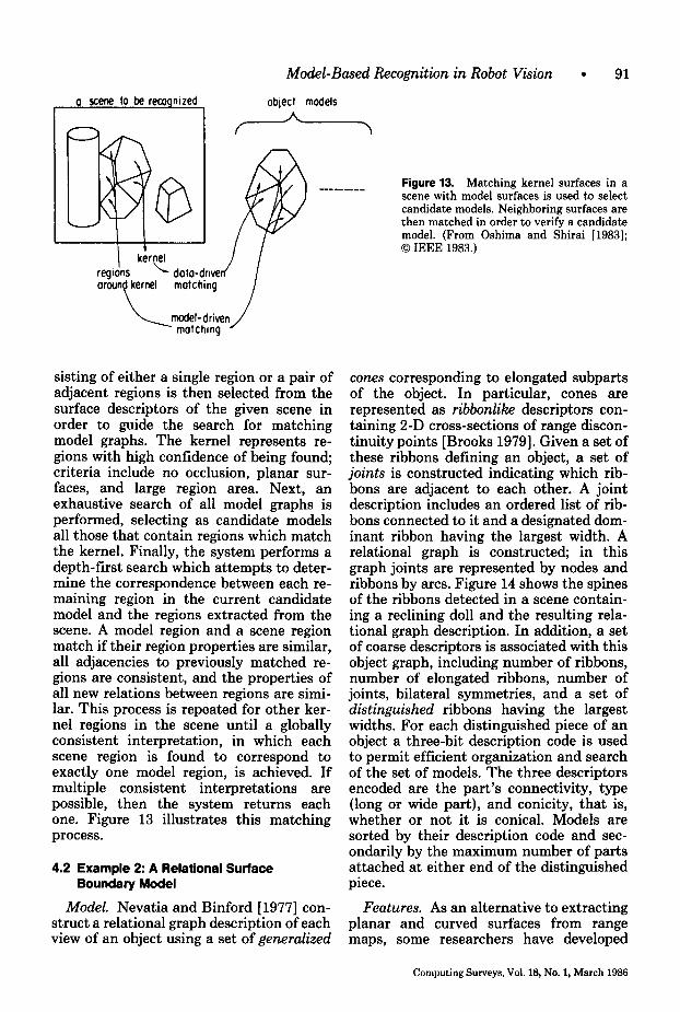
Model-Based Recognition in Robot Vision 91
a scene lo be recogmzed I
object models A
/ \
Figure 13. Matching kernel surfaces in a scene with model surfaces is used to select candidate models. Neighboring surfaces are then matched in order to verify a candidate model. (From Oshima and Shirai [1983]; 0 IEEE 1983.)
I I I t
kernel reg tons ‘I L doto-drw orcun kernel
L 1
matching
model-driven matching
sisting of either a single region or a pair of adjacent regions is then selected from the surface descriptors of the given scene in order to guide the search for matching model graphs. The kernel represents re- gions with high confidence of being found; criteria include no occlusion, planar sur- faces, and large region area. Next, an exhaustive search of all model graphs is performed, selecting as candidate models all those that contain regions which match the kernel. Finally, the system performs a depth-first search which attempts to deter- mine the correspondence between each re- maining region in the current candidate model and the regions extracted from the scene. A model region and a scene region match if their region properties are similar, all adjacencies to previously matched re- gions are consistent, and the properties of all new relations between regions are simi- lar. This process is repeated for other ker- nel regions in the scene until a globally consistent interpretation, in which each scene region is found to correspond to exactly one model region, is achieved. If multiple consistent interpretations are possible, then the system returns each one. Figure 13 illustrates this matching process.
4.2 Example 2: A Relational Surface Boundary Model
cones corresponding to elongated subparts of the object. In particular, cones are represented as ribbonlike descriptors con- taining 2-D cross-sections of range discon- tinuity points [Brooks 19791. Given a set of these ribbons defining an object, a set of joints is constructed indicating which rib- bons are adjacent to each other. A joint description includes an ordered list of rib- bons connected to it and a designated dom- inant ribbon having the largest width. A relational graph is constructed; in this graph joints are represented by nodes and ribbons by arcs. Figure 14 shows the spines of the ribbons detected in a scene contain- ing a reclining doll and the resulting rela- tional graph description. In addition, a set of coarse descriptors is associated with this object graph, including number of ribbons, number of elongated ribbons, number of joints, bilateral symmetries, and a set of distinguished ribbons having the largest widths. For each distinguished piece of an object a three-bit description code is used to permit efficient organization and search of the set of models. The three descriptors encoded are the part’s connectivity, type (long or wide part), and conicity, that is, whether or not it is conical. Models are sorted by their description code and sec- ondarily by the maximum number of parts attached at either end of the distinguished piece.
Model. Nevatia and Binford [1977] con- Features. As an alternative to extracting struct a relational graph description of each planar and curved surfaces from range view of an object using a set of generalized maps, some researchers have developed
Computing Surveys, Vol. 18, No. 1, March 1986
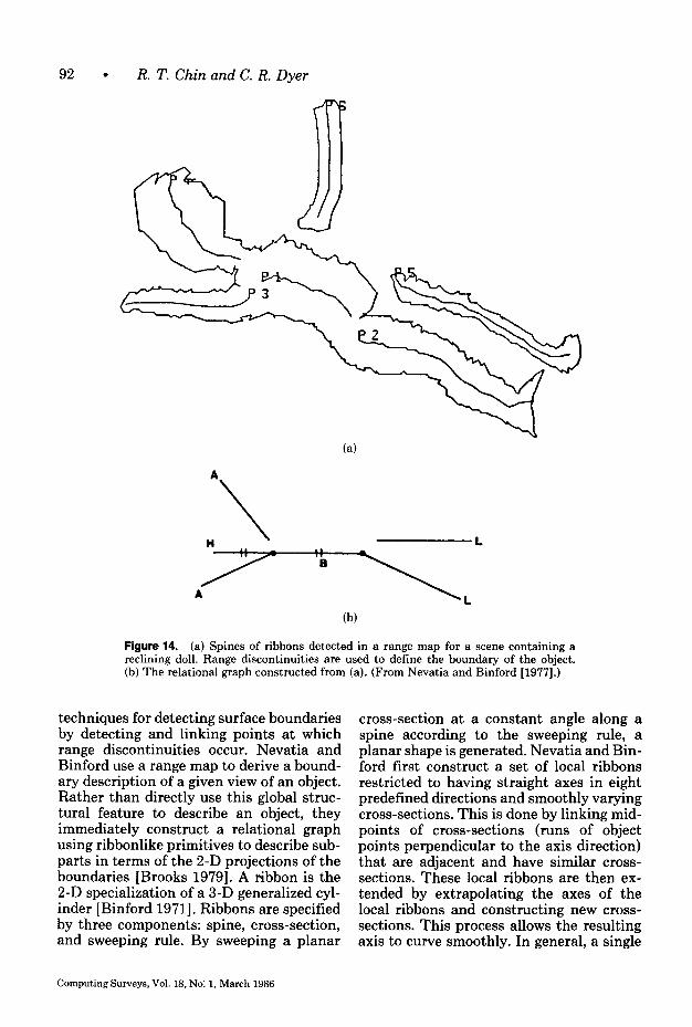
92 l R. T. Chin and C. R. Dyer
(a)
(b)
Figure 14. (a) Spines of ribbons detected in a range map for a scene containing a reclining doll. Range discontinuities are used to define the boundary of the object. (b) The relational graph constructed from (a). (From Nevatia and Binford [1977].)
techniques for detecting surface boundaries by detecting and linking points at which range discontinuities occur. Nevatia and Binford use a range map to derive a bound- ary description of a given view of an object. Rather than directly use this global struc- tural feature to describe an object, they immediately construct a relational graph using ribbonlike primitives to describe sub- parts in terms of the 2-D projections of the boundaries [Brooks 19791. A fibbon is the 2-D specialization of a 3-D generalized cyl- inder [Binford 19711. Ribbons are specified by three components: spine, cross-section, and sweeping rule. By sweeping a planar
cross-section at a constant angle along a spine according to the sweeping rule, a planar shape is generated. Nevatia and Bin- ford first construct a set of local ribbons restricted to having straight axes in eight predefined directions and smoothly varying cross-sections. This is done by linking mid- points of cross-sections (runs of object points perpendicular to the axis direction) that are adjacent and have similar cross- sections. These local ribbons are then ex- tended by extrapolating the axes of the local ribbons and constructing new cross- sections. This process allows the resulting axis to curve smoothly. In general, a single
Computing Surveys, Vol. 18, No. 1, March 1986
Model-Based Recognition in Robot Vision l 93
part of an object may be described by (part of) several overlapping ribbons. To reduce this redundancy, ribbons that are not so elongated or rectangular as other ribbons overlapping them are deleted. Each ribbon is associated with a crude description of its shape given by its axis length, average cross-section width, elongatedness, and type (conical or cylindrical).
Matching. As in the 2-D relational graph methods, matching involves comparing parts of the relational graph extracted from a given scene with each relational graph describing a model. First, a set of candidate models is determined by comparing the properties of the distinguished ribbons in the scene with those distinguished ribbons associated with each of the models. For each such candidate model a finer match is performed by comparing other ribbons, pairing a model ribbon with a scene ribbon if their properties are similar and all con- nectivity relations are consistent in the cur- rent pair of matched subgraphs. The scene graph is allowed to match a model graph, even if not all model ribbons are present in the scene graph (hence partial occlusion is permitted), but the scene graph may not contain extra ribbons that are not matched by any ribbon in the model graph.
4.3 Other Studies
Many researchers have investigated using range maps as the basis for segmenting an image into regions by grouping (merging) points into planar surfaces, cylindrical sur- faces, surfaces on generalized cylinders, and other smoothly curved surface patches [Agin and Binford 1976; Bolles 1981; Bolles and Fischler 1981; Duda et al. 1979; Hen- derson 1982; Henderson and Bhanu 1982; Milgram and Bjorklund 1980; Oshima and Shirai 1979; Popplestone et al. 1975; Shirai 19721. Alternatively, range maps can be segmented by locating discontinuities in depth. For example, Sugihara [1979] seg- ments a range map by finding such edges. To aid this process, a junction dictionary is precomputed listing all possible ways junc- tions can occur in range maps for scenes containing only trihedral objects. The dic-
tionary is then used to guide the search in the range map for edges of the appropriate types.
For the most part, however, the resulting surface and boundary descriptions have not been used to define corresponding viewer-centered object models and match- ing techniques. This is primarily be- cause object-centered 3-D models are more concise and natural representations than a set of independent 2$D models. Of course, many of the 3-D modeling and matching methods presented in Section 5 could be adapted and used for each distinct view- point.
5. 3-D OBJECT REPRESENTATIONS
If we assume that an object can occur in a scene at an arbitrary orientation in 3-space, then the model must contain a description of the object from all viewing angles. Image- space (2-D) and surface-space (2&D) rep- resentations are viewer centered, and each distinct view is represented indepen- dently. Thus, when multiple views of complicated objects are permitted (as in the general bin-picking problem), a viewpoint-independent, volumetric repre- sentation is preferred [Marr 19781. In ad- dition, in an industrial automation environ- ment in which the vision system must be integrated with objects represented in CAD databases, an object-space model may be convenient because of its compatibility. In contrast to the previous representations, a single model is used to represent an object, implicitly describing all possible views of the object.
Researchers have investigated two main types of 3-D representations. These are (1) exact representations using surface, sweep, and volume descriptions; (2) multi- view feature representations in which a set of 2-D or 2$-D descriptions are combined into a single composite model. This in- cludes the specification of a set of topolog- ically distinct views or a uniformly sampled set of 2-D viewpoints around an object. The first representation method completely describes an object’s spatial occupancy properties, whereas the second only rep- resents selected visible 2-D or 2&D surface
Computing Surveys, Vol. 18, No. 1, March 1966
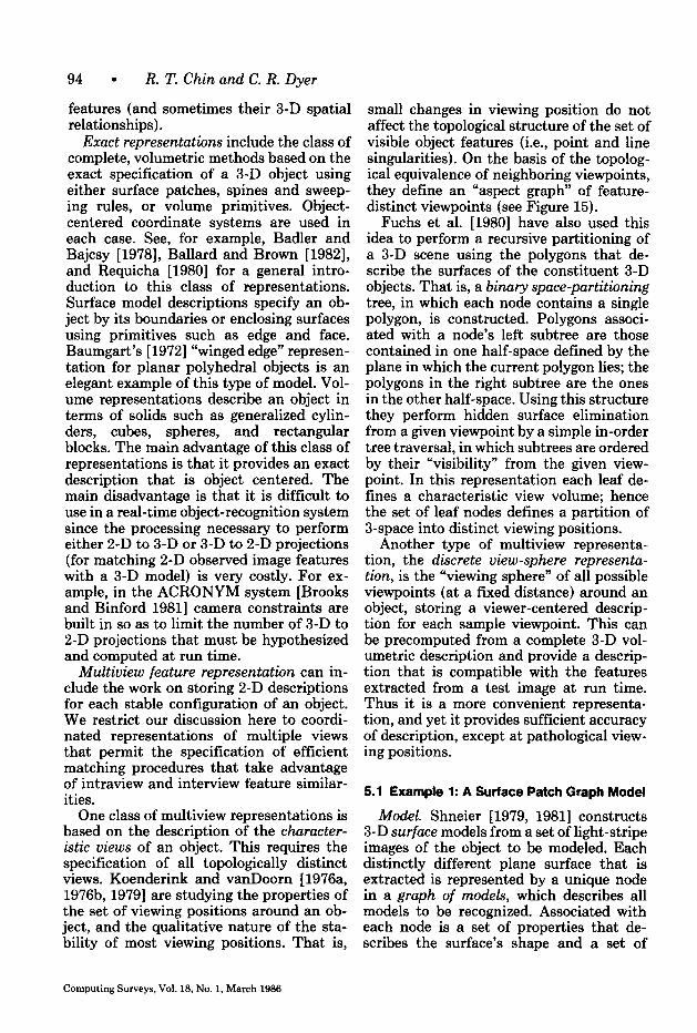
94 l R. T. Chin and C. R. Dyer
features (and sometimes their 3-D spatial relationships).
Exact representations include the class of complete, volumetric methods based on the exact specification of a 3-D object using either surface patches, spines and sweep- ing rules, or volume primitives. Object- centered coordinate systems are used in each case. See, for example, Badler and Bajcsy [ 19781, Ballard and Brown [1982], and Requicha [1980] for a general intro- duction to this class of representations. Surface model descriptions specify an ob- ject by its boundaries or enclosing surfaces using primitives such as edge and face. Baumgart’s [ 19721 “winged edge” represen- tation for planar polyhedral objects is an elegant example of this type of model. Vol- ume representations describe an object in terms of solids such as generalized cylin- ders, cubes, spheres, and rectangular blocks. The main advantage of this class of representations is that it provides an exact description that is object centered. The main disadvantage is that it is difficult to use in a real-time object-recognition system since the processing necessary to perform either 2-D to 3-D or 3-D to 2-D projections (for matching 2-D observed image features with a 3-D model) is very costly. For ex- ample, in the ACRONYM system [Brooks and Binford 19811 camera constraints are built in so as to limit the number of 3-D to 2-D projections that must be hypothesized and computed at run time.
Multiview feature representation can in- clude the work on storing 2-D descriptions for each stable configuration of an object. We restrict our discussion here to coordi- nated representations of multiple views that permit the specification of efficient matching procedures that take advantage of intraview and interview feature similar- ities.
One class of multiview representations is based on the description of the churacter- istic views of an object. This requires the specification of all topologically distinct views. Koenderink and vanDoorn [1976a, 1976b,1979] are studying the properties of the set of viewing positions around an ob- ject, and the qualitative nature of the sta- bility of most viewing positions. That is,
small changes in viewing position do not affect the topological structure of the set of visible object features (i.e., point and line singularities). On the basis of the topolog- ical equivalence of neighboring viewpoints, they define an “aspect graph” of feature- distinct viewpoints (see Figure 15).
Fuchs et al. [1980] have also used this idea to perform a recursive partitioning of a 3-D scene using the polygons that de- scribe the surfaces of the constituent 3-D objects. That is, a binary space-partitioning tree, in which each node contains a single polygon, is constructed. Polygons associ- ated with a node’s left subtree are those contained in one half-space defined by the plane in which the current polygon lies; the polygons in the right subtree are the ones in the other half-space. Using this structure they perform hidden surface elimination from a given viewpoint by a simple in-order tree traversal, in which subtrees are ordered by their “visibility” from the given view- point. In this representation each leaf de- fines a characteristic view volume; hence the set of leaf nodes defines a partition of 3-space into distinct viewing positions.
Another type of multiview representa- tion, the discrete view-sphere representa- tion, is the “viewing sphere” of all possible viewpoints (at a fixed distance) around an object, storing a viewer-centered descrip- tion for each sample viewpoint. This can be precomputed from a complete 3-D vol- umetric description and provide a descrip- tion that is compatible with the features extracted from a test image at run time. Thus it is a more convenient representa- tion, and yet it provides sufficient accuracy of description, except at pathological view- ing positions.
5.1 Example 1: A Surface Patch Graph Model
Model. Shneier [1979, 19811 constructs 3-D surface models from a set of light-stripe images of the object to be modeled. Each distinctly different plane surface that is extracted is represented by a unique node in a graph of models, which describes all models to be recognized. Associated with each node is a set of properties that de- scribes the surface’s shape and a set of
Computing Surveys, Vol. 18, No. 1, March 1986
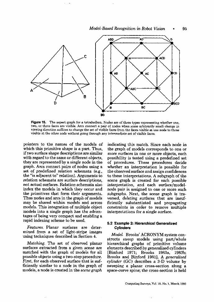
Model-Based Recognition in Robot Vision l 95
\
I
Figure 15. The aspect graph for a tetrahedron. Nodes are of three types representing whether one, two, or three faces are visible. Arcs connect a pair of nodes when some arbitrarily small change in viewing direction suffices to change the set of visible faces from the faces visible at one node to those visible at the other node without going through any intermediate set of visible faces.
pointers to the names of the models of which this primitive shape is a part. Thus, if two surface shape descriptions are similar with regard to the same or different objects, they are represented by a single node in the graph. Arcs connect pairs of nodes using a set of predefined relation schemata (e.g., the “is adjacent to” relation). Arguments to relation schemata are surface descriptions, not actual surfaces. Relation schemata also index the models in which they occur and the primitives that form their arguments. Thus nodes and arcs in the graph of models may be shared within models and across models. This integration of multiple object models into a single graph has the advan- tages of being very compact and enabling a rapid indexing scheme to be used.
Features. Planar surfaces are deter- mined from a set of light-stripe images using techniques described in Section 4.
Matching. The set of observed planar surfaces extracted from a given scene are matched with the graph of models for all possible objects using a two-step procedure. First, for each observed surface that is suf- ficiently similar to a node in the graph of models, a node is created in the scene graph
indicating this match. Since each node in the graph of models corresponds to one or more surfaces in one or more objects, each possibility is tested using a predefined set of procedures. These procedures decide whether an interpretation is possible for the observed surface and assign confidences to these interpretations. A subgraph of the scene graph is created for each possible interpretation, and each surface/model- node pair is assigned to one or more such subgraphs. Next, the scene graph is tra- versed, deleting surfaces that are insuf- ficiently substantiated and propagating constraints in order to remove multiple interpretations for a single surface.
5.2 Example 2: Hierarchical Generalized Cylinders
Model. Brooks’ ACRONYM system con- structs sweep models using part/whole hierarchical graphs of primitive volume elements described by generalized cylinders [Binford 1971; Brooks 1983a, 1983b; Brooks and Binford 19811. A generalized cylinder (GC) describes a 3-D volume by sweeping a planar cross-section along a space-curve spine; the cross-section is held
Computing Surveys, Vol. 18, No. 1, March 1986
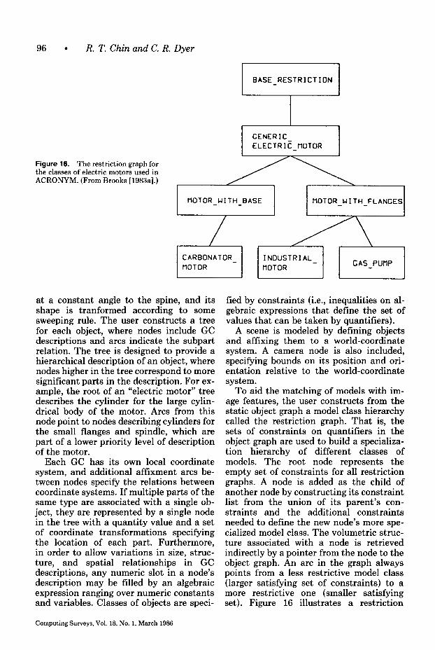
96 l R. T. Chin and C. R. Dyer
BASE RESTRICTION
Figure 16. The restriction graph for the classes of electric motors used in ACRONYM. (From Brooks [1983a].)
MOTOR WITH BASE tIOTOR WITH FLANGES
CARBONATOR tlOTOR -
INOUSTRIAL-
fIOTOR GAS PUtlP
at a constant angle to the spine, and its shape is tranformed according to some sweeping rule. The user constructs a tree for each object, where nodes include GC descriptions and arcs indicate the subpart relation. The tree is designed to provide a hierarchical description of an object, where nodes higher in the tree correspond to more significant parts in the description. For ex- ample, the root of an “electric motor” tree describes the cylinder for the large cylin- drical body of the motor. Arcs from this node point to nodes describing cylinders for the small flanges and spindle, which are part of a lower priority level of description of the motor.
Each GC has its own local coordinate system, and additional affixment arcs be- tween nodes specify the relations between coordinate systems. If multiple parts of the same type are associated with a single ob- ject, they are represented by a single node in the tree with a quantity value and a set of coordinate transformations specifying the location of each part. Furthermore, in order to allow variations in size, struc- ture, and spatial relationships in GC descriptions, any numeric slot in a node’s description may be filled by an algebraic expression ranging over numeric constants and variables. Classes of objects are speci-
Computing Surveys, Vol. 18, No. 1, March 1986
tied by constraints (i.e., inequalities on al- gebraic expressions that define the set of values that can be taken by quantifiers).
A scene is modeled by defining objects and affixing them to a world-coordinate system. A camera node is also included, specifying bounds on its position and ori- entation relative to the world-coordinate system.
To aid the matching of models with im- age features, the user constructs from the static object graph a model class hierarchy called the restriction graph. That is, the sets of constraints on quantifiers in the object graph are used to build a specializa- tion hierarchy of different classes of models. The root node represents the empty set of constraints for all restriction graphs. A node is added as the child of another node by constructing its constraint list from the union of its parent’s con- straints and the additional constraints needed to define the new node’s more spe- cialized model class. The volumetric struc- ture associated with a node is retrieved indirectly by a pointer from the node to the object graph. An arc in the graph always points from a less restrictive model class (larger satisfying set of constraints) to a more restrictive one (smaller satisfying set). Figure 16 illustrates a restriction
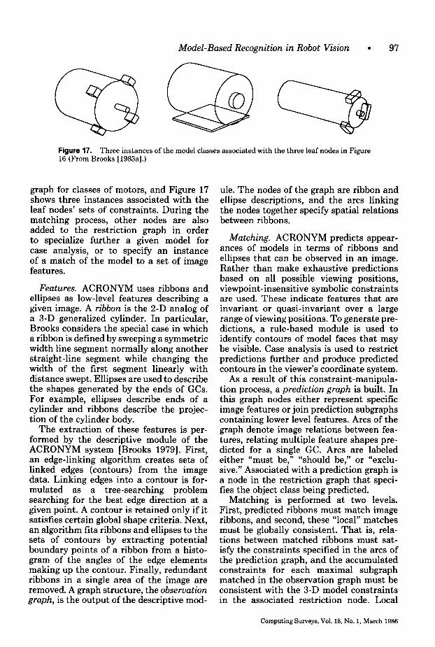
Model-Based Recognition in Robot Vision l 97
Figure 17. Three instances of the model classes associated with the three leaf nodes in Figure lf?(From Brooks [1983a].)
graph for classes of motors, and Figure 17 shows three instances associated with the leaf nodes’ sets of constraints. During the matching process, other nodes are also added to the restriction graph in order to specialize further a given model for case analysis, or to specify an instance of a match of the model to a set of image features.
Features. ACRONYM uses ribbons and ellipses as low-level features describing a given image. A ribbon is the 2-D analog of a 3-D generalized cylinder. In particular, Brooks considers the special case in which a ribbon is defined by sweeping a symmetric width line segment normally along another straight-line segment while changing the width of the first segment linearly with distance swept. Ellipses are used to describe the shapes generated by the ends of GCs. For example, ellipses describe ends of a cylinder and ribbons describe the projec- tion of the cylinder body.
The extraction of these features is per- formed by the descriptive module of the ACRONYM system [Brooks 19791. First, an edge-linking algorithm creates sets of linked edges (contours) from the image data. Linking edges into a contour is for- mulated as a tree-searching problem searching for the best edge direction at a given point. A contour is retained only if it satisfies certain global shape criteria. Next, an algorithm fits ribbons and ellipses to the sets of contours by extracting potential boundary points of a ribbon from a histo- gram of the angles of the edge elements making up the contour. Finally, redundant ribbons in a single area of the image are removed. A graph structure, the observation graph, is the output of the descriptive mod-
ule. The nodes of the graph are ribbon and ellipse descriptions, and the arcs linking the nodes together specify spatial relations between ribbons.
Matching. ACRONYM predicts appear- ances of models in terms of ribbons and ellipses that can be observed in an image. Rather than make exhaustive predictions based on all possible viewing positions, viewpoint-insensitive symbolic constraints are used. These indicate features that are invariant or quasi-invariant over a large range of viewing positions. To generate pre- dictions, a rule-based module is used to identify contours of model faces that may be visible. Case analysis is used to restrict predictions further and produce predicted contours in the viewer’s coordinate system.
As a result of this constraint-manipula- tion process, a prediction graph is built. In this graph nodes either represent specific image features or join prediction subgraphs containing lower level features. Arcs of the graph denote image relations between fea- tures, relating multiple feature shapes pre- dicted for a single GC. Arcs are labeled either “must be,” “should be,” or “exclu- sive.” Associated with a prediction graph is a node in the restriction graph that speci- fies the object class being predicted.
Matching is performed at two levels. First, predicted ribbons must match image ribbons, and second, these “local” matches must be globally consistent. That is, rela- tions between matched ribbons must sat- isfy the constraints specified in the arcs of the prediction graph, and the accumulated constraints for each maximal subgraph matched in the observation graph must be consistent with the 3-D model constraints in the associated restriction node. Local
Computing Surveys, Vol. 18, No. 1, March 1986
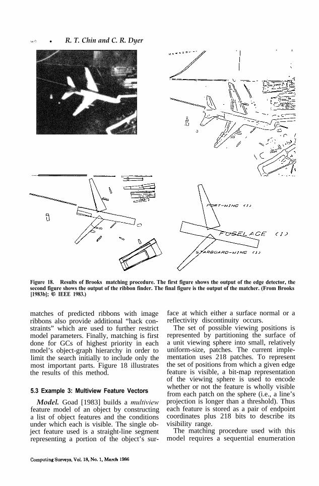
98 l R. T. Chin and C. R. Dyer
Figure 18. Results of Brooks’ matching procedure. The first figure shows the output of the edge detector, thesecond figure shows the output of the ribbon finder. The final figure is the output of the matcher. (From Brooks[1983b]; 0 IEEE 1983.)
matches of predicted ribbons with imageribbons also provide additional “hack con-straints” which are used to further restrictmodel parameters. Finally, matching is firstdone for GCs of highest priority in eachmodel’s object-graph hierarchy in order tolimit the search initially to include only themost important parts. Figure 18 illustratesthe results of this method.
5.3 Example 3: Multiview Feature Vectors
Model. Goad [1983] builds a multiviewfeature model of an object by constructinga list of object features and the conditionsunder which each is visible. The single ob-ject feature used is a straight-line segmentrepresenting a portion of the object’s sur-
face at which either a surface normal or areflectivity discontinuity occurs.
The set of possible viewing positions isrepresented by partitioning the surface ofa unit viewing sphere into small, relativelyuniform-size, patches. The current imple-mentation uses 218 patches. To representthe set of positions from which a given edgefeature is visible, a bit-map representationof the viewing sphere is used to encodewhether or not the feature is wholly visiblefrom each patch on the sphere (i.e., a line’sprojection is longer than a threshold). Thuseach feature is stored as a pair of endpointcoordinates plus 218 bits to describe itsvisibility range.
The matching procedure used with thismodel requires a sequential enumeration
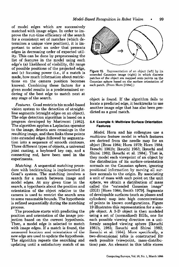
Model-Based Recognition in Robot Vision l 99
of model edges which are successively matched with image edges. In order to im- prove the run-time efficiency of the search for a consistent set of matches (which de- termines a unique view position), it is im- portant to select an order that presents edges in decreasing order of expected util- ity. This can be done by preprocessing the list of features in the model using each edge’s (a) likelihood of visibility, (b) range of possible positions of the projected edge, and (c) focusing power (i.e., if a match is made, how much information about restric- tions on the camera position becomes known). Combining these factors for a given model results in a predetermined or- dering of the best edge to match next at any stage of the search.
Features. Goad restricts his model-based vision system to the detection of straight- line segments (straight edges on an object). The edge detection algorithm is based on a program developed by Marimont [1982]. The algorithm applies a Laplacian operator to the image, detects zero crossings in the resulting image, and then links these points into extended edges followed by segmenta- tion into a sequence of smooth contours. Three different types of objects, a universal joint casting, a keyboard key cap, and a connecting rod, have been used in the experiments.
Matching. A sequential matching proce- dure with backtracking is implemented in Goad’s system. The matching involves a search for a match between image and model edges. At any given time in the search, a hypothesis about the position and orientation of the object relative to the camera is used to restrict the search area to some reasonable bounds. The hypothesis is refined sequentially during the matching process.
The procedure starts with predicting the position and orientation of the image pro- jection based on the current hypothesis. Then, a model edge is selected to match with image edges. If a match is found, the measured location and orientation of the new edge are used to update the hypothesis. The algorithm repeats the searching and updating until a satisfactory match of an
Figure 19. Representation of an object (left) by its extended Gaussian image (right) in which discrete patches of the object are mapped onto points on the Gaussian sphere based on the surface orientation of each patch. (From Horn [1984].)
object is found. If the algorithm fails to locate a predicted edge, it backtracks to use another image edge that has also been pre- dicted as a good match.
5.4 Example 4: Multiview Surface Orientation Features
Model. Horn and his colleagues use a multiview feature model in which features are derived from the needle map for an object [Brou 1984; Horn 1979; Horn 1984; Ikeuchi 1981b; Ikeuchi 1983; Ikeuchi and Shirai 1982; Ikeuchi et al. 19841. That is, they model each viewpoint of an object by the distribution of its surface-orientation normals on the Gaussian sphere, ignoring positional information by moving all sur- face normals to the origin. By associating a unit of mass with each point on the unit sphere, we obtain a distribution of mass called the “extended Gaussian image” (EGI) [Horn 1984; Smith 19791. Segments of developable surfaces (such as planes and cylinders) map into high concentrations of points in known configurations. Figure 19 illustrates this representation for a sim- ple object. A 3-D object is then modeled using a set of (normalized) EGIs, one for each possible viewing direction on a uni- formly sampled viewing sphere [Ikeuchi 1981b, 1983; Ikeuchi and Shirai 1982; Ikeuchi et al. 19841. More specifically, a two-dimensional table is constructed &r each possible (viewpoint, mass-distribu- tion) pair. An element in this table stores
Computing Surveys, Vol. 18, No. 1, March 1986
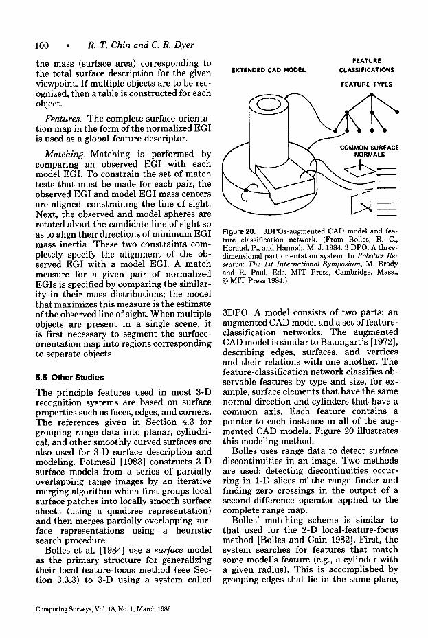
100 l R. T. Chin and C. R. Dyer
the mass (surface area) corresponding to the total surface description for the given viewpoint. If multiple objects are to be rec- ognized, then a table is constructed for each object.
Features. The complete surface-orienta- tion map in the form of the normalized EGI is used as a global-feature descriptor.
Matching. Matching is performed by comparing an observed EGI with each model EGI. To constrain the set of match tests that must be made for each pair, the observed EGI and model EGI mass centers are aligned, constraining the line of sight. Next, the observed and model spheres are rotated about the candidate line of sight so as to align their directions of minimum EGI mass inertia. These two constraints com- pletely specify the alignment of the ob- served EGI with a model EGI. A match measure for a given pair of normalized EGIs is specified by comparing the similar- ity in their mass distributions; the model that maximizes this measure is the estimate of the observed line of sight. When multiple objects are present in a single scene, it is first necessary to segment the surface- orientation map into regions corresponding to separate objects.
5.5 Other Studies
The principle features used in most 3-D recognition systems are based on surface properties such as faces, edges, and corners. The references given in Section 4.3 for grouping range data into planar, cylindri- cal, and other smoothly curved surfaces are also used for 3-D surface description and modeling. Potmesil [ 19831 constructs 3-D surface models from a series of partially overlapping range images by an iterative merging algorithm which first groups local surface patches into locally smooth surface sheets (using a quadtree representation) and then merges partially overlapping sur- face representations using a heuristic search procedure.
Bolles et al. [1984] use a surface model as the primary structure for generalizing their local-feature-focus method (see Sec- tion 3.3.3) to 3-D using a system called
EXTENDED CAD MODEL FEATURE
CLASSIFICATIONS
FEATURE TYPES
COMMON SURFACE
Figure 20. 3DPOs-augmented CAD model and fea- ture classification network. (From Bolles, R. C., Horaud, P., and Hannah, M. J. 1984.3 DPO: A three- dimensional part orientation system. In Robotics Re- search: The 1st International Symposium, M. Brady and R. Paul, Eds. MIT Press, Cambridge, Mass., 0 MIT Press 1984.)
3DP0. A model consists of two parts: an augmented CAD model and a set of feature- classification networks. The augmented CAD model is similar to Baumgart’s [ 19721, describing edges, surfaces, and vertices and their relations with one another. The feature-classification network classifies ob- servable features by type and size, for ex- ample, surface elements that have the same normal direction and cylinders that have a common axis. Each feature contains a pointer to each instance in all of the aug- mented CAD models. Figure 20 illustrates this modeling method.
Bolles uses range data to detect surface discontinuities in an image. Two methods are used: detecting discontinuities occur- ring in 1-D slices of the range finder and finding zero crossings in the output of a second-difference operator applied to the complete range map.
Bolles’ matching scheme is similar to that used for the 2-D local-feature-focus method [Bolles and Cain 19821. First, the system searches for features that match some model’s feature (e.g., a cylinder with a given radius). This is accomplished by grouping edges that lie in the same plane,
Computing Surveys, Vol. 18, No. 1, March 1986
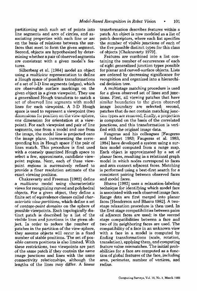
Model-Based Recognition in Robot Vision l 101
partitioning each such set of points into line segments and arcs of circles, and as- sociating properties with each line or arc on the basis of relations between the sur- faces that meet to form the given segment. Second, objects are hypothesized by deter- mining whether a pair of observed segments are consistent with a given model’s fea- tures.
Silberberg et al. [1984] model an object using a multiview representation to define a Hough space of possible transformations of a set of 3-D line segments (edges), which are observable surface markings on the given object in a given viewpoint. They use a generalized Hough transform to match a set of observed line segments with model lines for each viewpoint. A 3-D Hough space is used to represent a viewpoint (two dimensions for position on the view-sphere, one dimension for orientation at a view- point). For each viewpoint and pair of line segments, one from a model and one from the image, the model line is projected onto the image plane, incrementing the corre- sponding bin in Hough space if the pair of lines match. This procedure is first used with a coarsely quantized Hough space to select a few, approximate, candidate view- point regions. Next, each of these view- point regions is successively refined to provide a finer resolution estimate of the exact viewing position.
Chakravarty and Freeman [1982] define a multiview model using characteristic views for recognizing curved and polyhedral objects. For a given object, they define a finite set of equivalence classes called char- acteristic view partitions, which define a set of vantage-point domains on the sphere of possible viewpoints. Each topologically dis- tinct patch is described by a list of the visible lines and junctions in the given ob- ject. In order to reduce the number of patches in the partition of the view-sphere, they assume objects will occur in a fixed number of stable positions. The set of pos- sible camera positions is also limited. With these restrictions, two viewpoints are part of the same patch if they contain the same image junctions and lines with the same connectivity relationships, although the lengths of the lines may differ. A linear
transformation describes features within a patch. An object is now modeled as a list of patch descriptors, where each list specifies the number of visible junctions of each of the five possible distinct types for this class of objects [Chakravarty 19791.
Features are combined into a list con- taining the number of occurrences of each of eight generalized junction types possible for planar and curved-surface objects. Lists are ordered by decreasing significance for recognition and organized into a hierarchi- cal decision tree.
A multistage matching procedure is used for a given observed set of lines and junc- tions. First, all viewing patches that have similar boundaries to the given observed image boundary are selected; second, patches that do not contain matching junc- tion types are removed; finally, a projection is computed on the basis of the correlated junctions, and this transformation is veri- fied with the original image data.
Faugeras and his colleagues [Faugeras and Hebert 1983; Faugeras et al. 1983, 19841 have developed a system using a sur- face model computed from a range map. Each object is approximated by a set of planar faces, resulting in a relational graph model in which nodes correspond to faces and arcs connect adjacent faces. Matching is performed using a best-first search for a consistent pairing between observed faces and model faces.
Bhanu [1982] uses a relaxation-labeling technique for identifying which model face is associated with each observed image face. Range data are first merged into planar faces [Henderson and Bhanu 19821. A two- stage relaxation procedure is then used. In the first stage compatibilities between pairs of adjacent faces are used, in the second stage compatibilities between a face and two of its neighboring faces are used. The compatibility of a face in an unknown view with a face in a model is computed by finding transformations (scale, rotation, translation), applying them, and computing feature value mismatches. The initial prob- abilities for a face are computed as a func- tion of global features of the face, including area, perimeter, number of vertices, and radius.
Computing Surveys, Vol. 18, No. 1, March 1986
102 l R. T. Chin and C. R. Dyer
Grimson and Lozano-Perez [1984] define a hypothesize-and-test search procedure for matching a set of observed surface points (specified by their 3-D position and surface orientation) with a set of polyhedral models (specified by their planar faces). All feasible interpretations of the observed point data are constructed by determining consistent pairings of points to model faces (a point may be mapped into any location on the associated face). Interpretations that are locally inconsistent are rejected. That is, they exploit local constraints on nearby points involving properties such as distance, angle, and direction to rapidly reduce the candidate pairings between a given point and the model faces. For each feasible interpretation of the point data, a final consistency check is made to verify the match.
6. RELATED SURVEYS
There have been published recently a num- ber of survey papers and tutorials that provide selected information on computer vision for industrial automation and robot- ics. Most of these papers have been organ- ized as summaries of the latest robot vision systems and techniques. In contrast, this paper has attempted to present a more complete listing of results and uses a com- mon descriptive format to clarify similari- ties and differences in the approaches.
Rosen [ 19791 examined the desired func- tions and industrial requirements for machine vision that are applicable to sensor-controlled manipulation. Industrial implementations, as well as selected re- search problems, are described. Examples are grouped into bin picking, the manipu- lation of isolated parts on conveyors, the manipulation in manufacturing and assembly, and visual inspection. He also comments that present machine vision techniques are sufficiently advanced to be used in factories in a cost-effective way.
Myers [1980] presents a survey of exist- ing systems, including operational systems in manufacturing and feasibility demon- strations. He describes work done at Gen- eral Motors Research Laboratories (one of the first to apply computer vision technol-
ogy to a production line), as well as other inspection systems. Yachida and Tsuji [ 19801 survey industrial machine vision activities in Japan and present a number of successful vision systems that are now operational in Japanese manufacturing. Chin [1982] presents a bibliography on industrial vision for discrete parts.
Kruger and Thompson [1981] present a summary and survey of techniques and ap- plications relevant to the field. They look at generic examples in the areas of inspec- tion, part recognition, and discrete compo- nent assembly, and discuss sample systems that exemplify the current state of the art. The authors also make economic projec- tions and given recommendations to guide future investigations. The survey concludes with some comments on the fact that the efficacy of the techniques in any applica- tion of machine vision depends on both technical factors and economic considera- tions.
Foith et al. [ 19811 discuss selected meth- ods in image processing and analysis re- lated to industrial applications and point out why practical systems perform binary image processing. A brief survey and some specific approaches used in several state- of-the-art systems are presented.
Bolles [1981] reviews some possible ap- plications of image-understanding research to industrial automation, and compares the characteristics of current image- understanding systems with that of indus- trial automation systems. He points out a few ways in which current image-under- standing techniques may be used in the future to enhance the capabilities of indus- trial systems.
Binford [1982] presents a survey of sev- eral general-purpose, model-based image- analysis systems and points out many of the weaknesses of current systems. Besl and Jain [1985] survey general methods for three-dimensional object recognition. Brady [1982a] presents a general survey of image-understanding research.
Kinnucan [1983] briefly looks at the de- velopment of machine vision in the United States in the past twenty years and surveys the current activities of several major re- search laboratories and industries. He also
Computing Surveys, Vol. 18, NO. 1, March 1986
Model-Based Recognition in Robot Vision l 103
examines current market activities of ex- isting commercial machine vision systems.
On automated visual inspection, Jarvis [1980] uses three practical examples to il- lustrate the nature of the techniques and problems. Chin and Harlow [1982] present an extensive survey and discuss the inspec- tion of printed circuit boards, photomasks, and IC chips. Porter and Mundy [1980] provide a comprehensive list of the types of visual-inspection techniques currently in use.
Other related surveys and overviews in- clude Agin [1980], Aleksander et al. [1983], Casler [1983], FU [1983], Kelly [1983], Kelly et al. [1983], Pot et al. [1983], Pugh [1983], Ross01 [1983], Trombly [1982], Tropf et al. [1982], and West [1982].
7. SUMMARY
An extensive review of robot vision tech- niques for industrial parts recognition has been presented. The major motivation for using industrial machine vision is to in- crease flexibility and reduce cost of these tasks. Up to the present, primarily very simple techniques based on 2-D global sca- lar features have been applied in real-time manufacturing processes. More sophisti- cated techniques will have to be developed in order to deal with less structured indus- trial environments and permit more task versatility. These techniques will incorpo- rate higher level modeling (e.g., highly organized graph models containing 2$-D and 3-D descriptions), more powerful feature-extraction methods (e.g., global structural features of object boundaries, surfaces, and volumes), and more robust matching procedures for efficiently com- paring large sets of complex models with observed image features.
Recent trends indicate that multiple, dis- parate sensor types, including vision, range, and tactile sensors, will significantly im- prove the quality of the features that can be determined about a scene. The use of 3-D models is essential for reliably recog- nizing parts in the presence of significant uncertainty about their identities and positions in a robot’s workspace. The choice of a 3-D representation that can be
efficiently used with a matching procedure is still an important research question, however. As more experience is gained, sig- nificant speed improvements can be ex- pected with special-purpose hardware for performing this costly search task.
ACKNOWLEDGMENTS
This work was supported in part by the National Science Foundation under grants ECS-8352356 and ECS-8301521, and in part by the General Motors Foundation, Inc., Dearborn, Michigan.
REFERENCES
AGIN, G. J. 1980. Computer vision systems for in- dustrial inspection and assembly. Computer 13,5 (May), 11-20.
AGIN, G. J., AND BINFORD, T. 0. 1976. Computer description of curved objects. IEEE Trans. Com- put. 25, 4 (Apr.), 439-449.
AGIN, G. J., AND DUDA, R. 0. 1975. SRI vision research for advanced automation. In Proceedings of the 2nd U.S.A.-Japan Computer Conference (Tokyo, Japan, Aug.), pp. 113-117.
AGIN, G. J., AND HIGHNAM, P. T. 1982. A movable light-stripe sensor for obtaining three-dimen- sional coordinate measurements. In Proceedings of the S0ciet.y of Photo-Optical Instrumentation Engineers Cinfirence on Robotics and Industrial Znsoection (San Dieeo, Calif.. Aug.), vol. 360. SPIE, Bellingham, Wash. -
ALEKSANDER, I., STONHAM, T. J., AND WILKIE, B. A. 1983. Computer vision systems for industry: Comparisons. In Artificial-Vision for Robots, i. Aleksander. Ed. Chanman and Hall, New York. pp. 179-196. -
ALTSCHULER, M. D., POSDAMER, J. L., FRIEDER, G., ALTSCHULER, B. R., AND TABOADA, J. 1981. The numerical stereo camera. In Proceedings of the Society of Photo-Optical Instrumentation En- gineers Conference on 3-D Machine Perception (Washington, D.C., Apr.), vol. 283. SPIE, Bel- lingham, Wash., pp. 15-24.
AYACHE, N. J. 1983. A model-based vision system to identify and locate partially visible industrial parts. In Proceedings of the IEEE Computer So- ciety Conference on Computer Vision and Pattern Recoznition (Washineton. D.C.. June). IEEE, New-York, pp. 492-494
BADLER, N., AND BAJCSY, R. 1978. Three-dimen- sional representations for computer graphics and computer vision. ACM Comput. Gr. 12, 3 (Aug.), 153-160.
BAIRD, M. L. 1978. Sight I: A computer vision sys- tem for automated IC chip manufacture. IEEE Trans. Syst. Man Cybern. 8,2 (Feb.), 133-139.
Computing Surveys. Vol. 18, No. 1, March 1966
104 l R. T. Chin and C. R. Dyer
BAJCSY, R. 1973. Computer identification of visual surface. Comput. Gr. Image Process. 2, 2 (Oct.), 118130.
BAJCSY, R., AND LIEBERMAN, L. 1976. Texture gra- dient as a depth cue. Comput. Gr. Image Process. 5, 1 (Mar.), 52-67.
BALLARD, D. H. 1981a. Generalizing the Hough transform to detect arbitrary shapes. Pattern Recogn. 13, 2, 111-122.
BALLARD, D. H. 1981b. Parameter networks: To- wards a theory of low level vision. In Proceedings of the 7th International Joint Conference on Ar- tificial Intelligence (Vancouver, Canada, Aug.). Kaufmann, Los Altos, Calif., pp. 1068-1078.
BALLARD, D. H., AND BROWN, C. M. 1982. Computer Vision. Prentice-Hall, Englewood Cliffs, N.J.
BARROW, H. G., AND TENENBAUM, J. M. 1978. Recovering intrinsic scene characteristics from images. In Computer Vision &stems. A. R. Han- - , son and E. M. Riseman, Eds. Academic Press, Orlando, Fla., pp. 3-26.
BARROW, H. G., AND TENENBAUM, J. M. 1981. Computational vision. Proc. IEEE 69, 5 (May), 572-595.
BAUMGART, B. G. 1972. Winged edge polyhedron representation. Tech. Rep. AIM-179, Computer Science Dept., Stanford Univ., Stanford, Calif.
BESL, P. J., AND JAIN, R. C. 1985. Three-dimen- sional object recognition. ACM Comput. Surv. 17, 1 (Mar.), 75-145.
BHANU, B. 1982. Surface representation and shape matching of 3-D objects. In Proceedings of the IEEE Computer Society Conference on Pattern Recognition and Image Processing (Las Vegas, Nev., June). IEEE, New York, pp. 349-354.
BHANU, B. 1983. Recognition of occluded objects. In Proceedings of the 8th International Joint Confer- ence on Artificial Intelligence (Karlsruhe, West Germany, Aug.). Kaufmann, Los Altos, Calif., pp. 1136-1138.
BHANU, B., AND FAUGERAS, 0. D. 1984. Shape matching of two-dimensional objects. IEEE Trans. Pattern Anal. Mach. Zntell. 6, 2 (Mar.), 137-156.
BINFORD, T. 0. 1971. Visual perception by com- puter. In the IEEE Systems Science and Cyber- netics Conference (Miami, Fla., Dec.). IEEE, New York.
BINFORD, T. 0. 1982. Survey of model-based image analysis systems. Znt. J. Robotics Res. 1, 1 (Spring), 18-63.
BIRK, J. R., KELLEY, R. B. CHEN, N.-Y., AND WILSON, L. 1979. Image feature extraction us- ing diameter-limited gradient direction histo- grams. IEEE Trans. Pattern Anal. Mach. Intell. I, 2 (Apr.), 228-235.
BIRK, J. R., KELLEY, R. B., AND MARTINS, H. 1981. An orienting robot for feeding workpieces stored in bins. IEEE Trans. Syst. Man Cybern. 1 I, 2 (Feb.), 151-160.
BOLLES, R. C. 1979a. Symmetry analysis of two- dimensional patterns for computer vision. In Pro-
ceedings of the 6th International Joint Conference on Artificial Intelligence (Tokvo. Janan. Aue.). Kaufmann, Los Altos, Calif., pp. 70-72. ’ -
BOLLES, R. C. 1979b. Robust feature matching through maximal cliques. In Proceedings of the Society of Photo-Optical Instrumentation Engi- neers Conference on Imaging Applications for Au- tomated Industrial Inspection and Assembly (Washington, D.C., Apr.), vol. 182. SPIE, Bel- lingham, Wash., pp. 140-149.
BOLLES, R. C. 1981. Overview of applications of image understanding to industrial automation. In Proceedings of the Society of Photo-Optical Imtru- mentation Engineers Conference on Techniques and Applications of Image Understanding (Wash- ington, D.C., Apr.), vol. 281. SPIE, Bellingham, Wash., pp. 134-140.
BOLLES, R. C., AND CAIN, R. A. 1982. Recognizing and locating partially visible objects: The local- feature-focus method. Int. J. Robotics Res. 1, 3, 57-82.
BOLLES, R. C., AND FISCHLER, M. A. 1981. A RANSAC-based approach to model fitting and its application to finding cylinders in range data. In Proceedings of the 7th International Joint Conference on Artificial Intelligence (Vancouver, Canada, Aug.). Kaufmann, Los Altos, Calif., pp. 637-643.
BOLLES, R. C., HORAUD, P., AND HANNAH, M. J. 1984. 3DPO: A three-dimensional part orienta- tion system. In Robotics Research: The 1st Znter- national Symposium, M. Brady and R. Paul, Eds. MIT Press, Cambridge, Mass., pp. 413-424.
BRADY, M. 1982a. Computational approaches to im- age understanding. ACM Comput. Surv. 14, 1 (Mar.), 3-71.
BRADY, M. 1982b. Parts description and acquisition using vision. In Proceedings of the Society of Photo-Optical Instrumentation Engineers Confer- ence on Robot Vision (Arlington, Va., May), vol. 336. SPIE, Bellingham, Wash., pp. 20-28.
BROOKS, R. A. 1979. Goal-directed edge linking and ribbon finding. In Proceedings of the Image Un- derstanding Workshop (Menlo Park. Calif.. Am.). Science Applications: Arlington, Va., pp. 72-76:
BROOKS, R. A. 1983a. Symbolic reasoning among 3-D models and 2-D images, Artif. Zntell. 17. 1 (Aug.), 285-348. - .
BROOKS, R. A. 1983b. Model-based three-dimen- sional interpretations of two-dimensional images. IEEE Trans. Pattern Anal. Mach. Intell. 5, 2 (Mar.), 140-150.
BROOKS, R. A., AND BINFORD, T. 0. 1981. Geometric modeling in vision for manufacturing. In Proceedings of the Society of Photo-Optical Instrumentation Engineers Conference on Robot Vision (Washington, D.C., Apr.), vol. 281. SPIE, Bellingham, Wash., pp. 141-159.
BROU, P. 1984. Using the Gaussian image to find the orientation of objects. Znt. J. Robotics Res. 3, 4 (Winter), 89-125.
BRUNE, W., AND BITTER, K. H. 1983. S.A.M. Opto- electronic picture sensor in a flexible manufac-
Computing Surveys, Vol. 18, No. 1, March 1986
Model-Based Recognition in Robot Vision
turing system. In Robot Vision, A. Pugh, Ed. Springer-Verlag, New York, pp. 325-337.
CASLER, R. J. 1983. Vision-guided robot part acqui- sition for assembly packaging applications. Tech. Paper MS83-219, Society of Manufacturing Engineers, Dearborn, Mich.
9 105
DUDA. R. 0.. NITZAN, D., AND BARRET. P. 1979. Use of range and reflectance data to find planar sur- face reeions. IEEE Trans. Pattern Anal. Mach. Intell. 7, 3 (July), 259-271.
FAUCERAS, 0. D., AND HEBERT, M. 1983. A 3-D recognition and positioning algorithm using geo- metrical matching between primitive surfaces. In Proceedings of the 8th International Joint Confer- ence on Artificial Intelligence (Karlsruhe, West Germany, Aug.). Kaufmann, Los Altos, Calif., pp. 996-1002.
CHAKRAVARTY, I. 1979. A generalized line and junc- tion labeling scheme with applications to scene analysis. IEEE Trans. Pattern Anal. Mach. Zntell. 1, 2 (Apr.), 202-205.
CHAKRAVARTY, I., AND FREEMAN, H. 1982. Char- acteristic views as a basis for three-dimensional object recognition. In Proceedings of the Society of Photo-Optical Instrumentation Engineers Con- ference on Robot Vision (Arlington, Va., May), vol. 336. SPIE, Bellingham, Wash., pp. 37-45.
CHEN, M. J., AND MILGRAM, D. L. 1982. A devel- opment system for machine vision. In Proceed- ings of the IEEE Computer Society Conference on Pattern Recognition and Image Processing (Las Vegas, Nev., June). IEEE, New York, pp. 512-517.
CHEN, N.-Y., BIRK, J. R., AND KELLEY, R. B. 1980. Estimating workpiece pose using the fea- ture points method. IEEE Trans. Auto. Control 25,6 (Dec.), 1027-1041.
CHENG, J. K., AND HUANG, T. S. 1981. Image rec- ognition by matching relational structure. In Proceedings of the IEEE Computer Societv Con- ference on Pattern Recognition and -Image Processing (Dallas. Tex.. Aug.). IEEE. New York, pp.542-547. ’ -’ ’
CHENG, J. K., AND HUANG, T. S. 1982. Recognition of curvilinear objects by matching relational structure. In Proceedings of the IEEE Computer Society Conference on Pattern Recognition and Image Processing (Las Vegas, Nev., June). IEEE, New York, pp. 343-348.
CHIN, R. T. 1982. Machine vision for discrete part handling in industry: A survey. In Conference Record of the Workshop on Industrial Applications of Machine Vision (Research Triangle Park, N.C., May). IEEE, New York, pp. 26-32.
CHIN, R. T., AND HARLOW, C. A. 1982. Automated visual inspection: A survey. IEEE Trans. Pattern Anal. Mach. Intell. 4, 6 (Nov.), 557-573.
CHOW, C. K., AND KANEKO, T. 1972. Automatic boundary detection of the left ventricle from cineangiograms. Comput. Biomed. Res. 5, 4 (Aug.), 388-410.
DESSIMOZ, J.-D. 1978a. Visual identification and lo- cation in a multiobject environment by contour tracking and curvature description. In Proceed- ings of the 8th International Symposium on In- dustrial Robots (Stuttgart, West Germany, May), pp. 746-776.
DESSIMOZ, J.-D. 1978b. Recognition and handling HENDERSON, T. C. 1982. Efficient segmentation of overlapping industrial parts. In Proceedings of method for range data. In Proceedings of the the International Symposium on Computer Vision Society of Photo-Optical Instrumentation Engi- and Sensor-Based Robots (Warren, Mich.. Sent.). General Motors Research Symposium, Warren,
neers Conference on Robot Vision (Arlington, Va., May), vol. 336. SPIE, Bellingham, Wash.,
Mich. pp. 46-47.
FAUGERAS, 0. D., GERMAIN, F., KRYZE, G., BOISSON- NAT, J., HEBERT, M., PONCE, J., PAUCHON, E., AND AYACHE, N. 1983. Towards a flexible vision system. In Robot Vision, A. Pugh, Ed. Springer- Verlag, New York, pp. 129-142.
FAUGERAS, 0. D., HEBERT, M., PAUCHON, E., AND PONCE, J. 1984. Object representation, identi- fication, and positioning from range data. In Ro- botics Research: The First International Sympo- sium, M. Brady and R. Paul, Eds. MIT Press, Cambridge, Mass., pp. 425-446.
FOITH, J. P., EISENBARTH, C., ENDERLS,E., GEISSEL- MANN, H., RINGSHAUSER, H., AND ZIMMER- MANN, G. 1981. Real-time processing of binary images for industrial applications. In Digital Zm- age Processing Systems, L. Bolt and Z. Kulpa, Eds. Springer-Verlag, Berlin, pp. 61-168.
FU, K. S. 1983. Robot vision for machine part rec- ognition. In Proceedings of the Society of Photo- Optical Instrumentation Engineers Conference on Robotics and Robot Sensing Systems (San Diego, Calif., Aug.), vol. 442. SPIE, Bellingham, Wash.
FUCHS, H.. KEDEM, Z. M.. AND NAYLOR. B. F. 1980. .On visible surface generation by a priori tree structures. In Proceedines of SIGRAPH ‘80 (Seattle, Wash., July). ACM,’ New York, pp. 124-133.
GLEASON, G. J., AND AGIN, G. J. 1979. A modular system for sensor-controlled manipulation and inspection. In Proceedings of the 9th International Symposium on Industrial Robots (Washington, D.C., Mar.). Society of Manufacturing Engineers, Dearborn, Mich., pp. 57-70.
GOAD, C. 1983. Special-purpose automatic program- ming for 3D model-based vision. In Proceedings of the Image Understanding Workshop (Arling- ton, Va., June). Science Applications, Arlington, Va., pp. 94-104.
GRIMSON, W. E. L., AND LOZANO-PEREZ, T. 1984. Model-based recognition and localization from sparse range or tactile data. Znt. J. Robotics Res. 3, 3 (Fall), 3-35.
HATTICH, W. 1982. Recognition of overlapping workpieces by model directed construction of object contours. Digital Syst. Znd. Autom. 1, 223-239.
Computing Surveys, Vol. 18, No. 1, March 1986
106 . R. T. Chin and C. R. Dyer
HENDERSON, T. C., AND BHANU, B. 1982. Three- point seed method for the extraction of planar faces from range data. In Conference Record of the Workshop on Industrial Applications of Ma- chine Vision (Research Triangle Park, N.C., May). IEEE, New York, pp. 181-186.
HOLLAND, S. W., ROSSOL, L., AND WARD, M. R. 1979. CONSIGHT-I: A vision-controlled robot system for transferring parts from belt conveyors. In Computer Vision and Sensor-Based Robots, G. G. Dodd and L. Rossol, Eds. Plenum, New York, pp. 81-97.
HORN, B. K. P. 1975a. A problem in computer vision: Orienting silicon integrated circuit chips for lead bonding. Comput. Gr. Image Process. 4, 3 (Sept.) 294-303.
HORN, B. K. P. 197513. Obtaining shape from shad- ing information. In The Psychology of Computer Vision. P. H. Winston. Ed. McGraw-Hill. New York, pp. 115-155.
HORN, B. K. P. 1979. SEQUINS and QUILLS- Representations for surface topography. Artifi- cial Intelliaence Laboratorv Memo 536. MIT. CambridgeyMass., May. ”
I I
HORN, B. K. P. 1984. Extended Gaussian images. Proc. IEEE 72, 12 (Dec.), 1671-1686.
HSIEH, Y. Y., AND FU, K. S. 1979. A method for automatic IC chip alignment and wire bonding. In Proceedings of the IEEE Computer Society Conference on Pattern Recognition and Image Processing (Chicago, Ill., Aug.). IEEE, New York, pp. 101-108.
HUECKEL, M. F. 1971. An operator which locates edges in digitized pictures. J. ACM 18, 1 (Jan.), 113-125.
IGARASHI, K., NARUSE, M., MIYAZAKI, S., AND YAMADA, T. 1979. Fully automated integrated circuit wire bonding system. In Proceedings of the 9th International Symposium on Industrial Robots (Washington, D.C., Mar.). Society of Manufac- turing Engineers, Dearborn, Mich., pp. 87-97.
IKEUCHI, K. 1981a. Determining surface orienta- tions of specular surfaces by using the photo- metric stereo method. IEEE Trans. Pattern Anal. Mach. Zntell. 3, 6 (Nov.), 661-669.
IKEUCHI, K. 1981b. Recognition of 3-D objects using the extended Gaussian image. In Proceedings of the 7th International Joint Conference on Artifi- cial Intelligence (Vancouver, Canada, Aug.). Kaufmann, Los Altos, Calif., pp. 595-600.
IKEUCHI, K. 1983. Determining the attitude of an object from a needle map using the extended Gaussian image. Artificial Intelligence Labora- tory Memo 714, M.I.T., Cambridge, Mass., Apr.
IKEUCHI, K., AND SHIRAI, Y. 1982. A model-based vision system for recognition of machine parts. In Proceedings of the National Conference on Artificial Intelligence (Pittsburgh, Pa., Aug.). Kaufmann, Los Altos, Calif., pp. 18-21.
IKEUCHI, K., HORN, B. K. P., NAGATA, S., CALLAHAN, KOENDERINK, J. J., AND VANDOORN A. J. 1976b. T., AND FEINGOLD, 0. 1984. Picking up an ob- Visual perception of rigidity of solid shape. ject from a pile of objects. In Robotics Research: J. Math. Biol. 3, 79-85.
The First International Symposium, M. Brady and R. Paul, Eds. MIT Press, Cambridge, Mass., pp. 1399162.
JAKUBOWSKI, R. 1982. Syntactic characterization of machine parts shapes, Cybern. Syst. 13, 1 (Jan.- Mar.), l-24.
JAKUBOWSKI, R., AND KASPRZAK, A. 1977. A syn- tactic description and recognition of rotary ma- chine elements. IEEE Trans. Comput. 26, 10 (Oct.), 1039-1042.
JARVIS, J. F. 1980. Visual inspection automation. Computer 13,5 (May), 32-39.
JARVIS, R. A. 1983a. A perspective on range finding techniques. IEEE Trans. Pattern Anal. Mach. Zntell. 5, 2 (Mar.), 122-139.
JARVIS, R. A. 1983b. A laser time-of-flight range scanner for robotic vision. IEEE Trans. Pattern Anal. Mach. Zntell. 5, 5 (Sept.), 505-512.
KANADE, T., AND ASADA, H. 1981. Noncontact visual three-dimensional ranging devices. In Pro- ceedings of the Society of Photo-Optical Znstru- mentation.Engineers Conference on 3-D Machine Perception (Washington. D.C.. Am.), vol. 283. SPIE; Bellingham, Wash., pp. 48-53..
KASHIOKA, S., EJIRI, M., AND SAKAMOTO, Y. 1976. A transistor wire-bonding system utilizing mul- tiple local pattern matching techniques. IEEE Trans. Syst. Man Cybern. 6,8 (Aug.), 562-569.
KASHIOKA, S., TAKEDA, S., SHIMA, Y., UNO, T., AND HAMADA, T. 1977. An approach to the inte- grated intelligent robot with multiple sensory feedback: Visual recognition techniques. In Pro- ceedings of the 7th International Symposium on Industrial Robots (Tokyo, Japan, Oct.). Japan Industrial Robot Association, pp. 531-538.
KELLEY, R. B. 1983. Binary and gray-scale robot vision. In Proceedings of the Society of Photo- Optical Instrumentation Engineers Conference on Robotics and Robot Sensing Systems (San Diego, Calif., Aug.), vol. 442. SPIE, Bellingham, Wash.
KELLEY, R. B., BIRK, J. R., MARTINS, H. A. S., ANI) TELLA, R. 1982. A robot system which acquires cylindrical workpieces from bins. IEEE Trans. Syst. Man Cybern. 12, 2 (Mar./Apr.), 204-213.
KELLEY, R. B., MARTINS, H. A. S., BIRK, J. R., ANI) DESSIMOZ, J.-D. 1983. Three vision algorithms for acquiring workpieces from bins. Proc. IEEE 71, 7 (July), 803-820.
KENDER, J. R. 1980. Shape from texture. Ph.D. dis- sertation, Computer Science Dept., Carnegie- Mellon Univ., Pittsburgh, Pa.
KINNUCAN, P. 1983. Machines that see. High Tech- nol. 3, 4 (Apr.), 30-36.
KITCHIN, P. W., AND PUGH, A. 1983. Processing of binary images. In Robot Vision, A. Pugh, Ed. Springer-Verlag, New York, pp. 21-42.
KOENDERINK, J. J., AND VANDOORN A. J. 1976s The singularities of the visual mapping. Biol. Cybern. 24, 51-59.
Computing Surveys, Vol. 18, No. 1, March 1986
Model-Based Recognition in Robot Vision 9 107
KOENDERINK, J. J., AND VANDOORN, A. J. 1979. The internal representation of solid shape with re- spect to vision. Biol. Cybern. 32, 211-216.
KRUGER, R. P., AND THOMPSON, W. B. 1981. A technical and economic assessment of computer vision for industrial inspection and robotic as- sembly. Proc. IEEE 69, 12 (Dec.), 1524-1538.
LIEBERMAN, L. 1979. Model-driven vision for indus- trial automation. In Advances in Digital Image Processing, P. Stucki, Ed. Plenum, New York, pp. 235-246.
MARIMONT, D. H. 1982. Segmentation in Acronym. In Proceedings of the Image Understanding Work- shop (Palo Alto. Cahf.. Sept.). Science Annhca- tions, Arlington; Va., p?. 223-229. a -
MARR, D. 1978. Representing visual information. In Computer Vision Systems, A. R. Hanson and E. M. Riseman, Eds. Academic Press, Orlando, Fla., pp. 61-80.
MARR, D. 1982. Vision. Freeman, San Francisco. MESE, M., YAMAZAKI, I., AND HAMADA, T. 1977. An
automatic position recognition technique for LSI assembly. In Proceedings of the 5th International Joint Conference on Artificial Intelligence (Cam- bridge, Mass., Aug.). Kaufmann, Los Altos, Calif., pp. 685-693.
MILCRAM, D. L., AND BJORKLUND, C. M. 1980. Range image processing: Planar surface extrac- tion. In Proceedings of the 5th International Con- ference on Pattern Recognition (Miami Beach, Fla., Dec.). IEEE, New York, pp. 912-919.
MYERS, W. 1980. Industry begins to use visual pat- tern recognition. Computer 13, 5 (May), 21-31.
NEVATIA, R., AND BINFORD, T. 0. 1977. Description and recognition of curved objects. Artif. Intell. 8, 1 (Jan.), 77-98.
OSHIMA, M., AND SHIRAI, Y. 1979. A scene descrip- tion method using three-dimensional informa- tion. Pattern Recogn. 11, 1, 9-17.
OSHIMA, M., AND SHIRAI, Y. 1983. Object recogni- tion using three-dimensional information. IEEE Trans. Pattern Anal. Mach. Intell. 5, 4 (July), 353-361.
PAGE, C. J., AND PUGH, A. 1981. Visually interactive gripping of engineering parts from random ori- entation. Digital Syst. Ind. Autom. 1, 1, 11-44.
PERKINS, W. A. 1978. A model-based vision system for industrial parts. IEEE Trans. Comput 27, 2 (Feb.), 126-143.
PERKINS, W. A. 1980. Area segmentation of images using edge points. IEEE Trans. Pattern Anal. Mach. Intell. 2, 1 (Jan.), 8-15.
PERSOON, E., AND FU., K. S. 1977. Shape discrimi- nation using Fourier descriptors. IEEE Trans. Syst. Man Cybern. 7,3 (Mar.), 170-179.
PIPITONE, F. J., AND MARSHALL, T. G. 1983. A wide- field scanning triangulation rangefinder for ma- chine vision. Int. J. Robotics Res. 2, 1 (Spring), 39-49.
POJE, J. F., AND DELP, E. J. 1982. A review of techniques for obtaining depth information with applications to machine vision. Tech. Rep. RSD-
TR-2-82, Center for Robotics and Integrated Manufacturing, Univ. of Michigan, Ann Arbor.
POPPLESTONE, R. J., BROWN, C. M., AMBLER, A. P., AND CRAWFORD, G. F. 1975. Forming models of plane-and-cylinder faceted bodies from light stripes. In Proceedings of the 4th International Joint Conference on Artificial Intelligence (Tbilisi, USSR, Sept.). Kaufmann, Los Altos, Calif., pp. 664-668.
PORTER, G. B., AND MUNDY, J. L. 1980. Visual inspection system design. Computer 23, 5 (May), 40-49.
POT, J., COIFFET, P., AND RIVES, P. 1983. Com- parison of five methods for the recognition of industrial parts, In Deoelopments in Robotics, B. Rooks, Ed. Springer-Verlag, New York.
POTMESIL, M. 1983. Generating models of solid objects by matching 3D surface segments. In Proceedings of the 8th International Joint Confer- ence on Artificial Intelligence (Karlsruhe, West Gernanv, Aua.). Kaufmann, Los Altos, Calif., pp. 1089-1093:
PUGH, A., ED. 1983. Robot Vision. Springer-Verlag, New York.
RAY, R. BIRK, J., AND KELLEY, R. B. 1983. Error analysis of surface normals determined by radi- ometrv. IEEE Trans. Pattern Anal. Mach. Intell. 5, 6 (rjov.,, 631-645.
REQUICHA, A. A. G. 1980. Representations for rigid solids: Theory, methods, and systems. ACM Comput. Sure. 22, 4 (Dec.), 437-464.
ROSEN, C. A. 1979. Machine vision and robotics: Industrial requirements. In Computer Vision and Sensor-Based Robots, G. G. Dodd and L. Rossol, Eds. Plenum, New York, pp. 3-20.
ROSEN C. A., AND GLEASON, G. J. 1981. Evaluating vision system performance. Robotics Today (Fall).
ROSENFELD, A., AND DAVIS L. S. 1979. Image seg- mentation and image models. Proc. IEEE 67, 5 (May), 764-772.
ROSSOL, L. 1983. Computer vision in industry. In Robot Vision, A. Pugh, Ed. Springer-Verlag, New York, pp. 11-18.
SCHACHTER, B. J. 1983. A matching algorithm for robot vision. In Proceedings of the IEEE Com- puter Society Conference oncomputer Vision and Pattern Recognition (Washington, D.C., June). IEEE, New York, pp. 490-491.
SEGEN, J. 1983. Locating randomly oriented objects from partial views. In Proceedings of the Society of Photo-Optical Instrumentation Engineers Con- ference on- Robot Vision and Sensory Controls, (Cambridee, Mass.. Nov.). vol. 449. SPIE. Bel- lingham, Wash.
SHIRAI, Y. 1972. Recognition of polyhedrons with a range tinder. Pattern Recogn. 4, 3 (Oct.), 243-250.
SHIRAI, Y. 1975. Edge finding, segmentation of edges and recognition of complex objects. In Proceed- ings of the 4th International Joint Conference on Artificial Intelligence (Tbilisi, USSR, Sept.). Kaufmann, Los Altos, Calif., pp. 674-681.
Computing Surveys, Vol. 18, No. 1, March 1986
108 l R. T. Chin and C. R. Dyer
SHIRAI, Y. 1978. Recognition of real-world objects using edge cues. In Computer Vision Systems, A. R. Hanson and E. M. Riseman, Eds. Academic Press, New York, pp. 353-362.
SHNEIER, M. 1979. A compact relational structure representation. In Proceedings of the 6th Inter- national Joint Conference on Artificial Intelligence (Tokyo, Japan, Aug.). Kaufmann, Los Altos, Calif., pp. 818-826.
SHNEIER, M. 1981. Models and strategies for match- ine in industrial vision. Tech. Rep. TR-1073, Computer Science Dept., Univ. of Maryland, College Park, July.
SILBERBERG, T. M., DAVIS, L. S., AND HARWOOD, D. 1984. An iterative Hough procedure for three- dimensional object recognition. Pattern Recogn. I: 6,621-629.
SILVER, W. M. 1980. Determining shape and reflec- tance using multiple images. M.Sc. thesis, M.I.T., Cambridge, Mass.
SMITH, D. A. 1979. Using enhanced spherical images for object representation. Artificial Intelligence Laboratory Memo 530, M.I.T., Cambridge, Mass., May.
STEVENS, K. A. 1981. The information content of texture gradients. Bial. Cybern. 42,95-105.
STOCKMAN, G. C. 1980. Recognition of parts and their orientation for automatic machining, han- dline and insoection. ROD. NSF-SIBR-Phase I. NTIS Order PB 80-178813.
STOCKMAN, G. C., KOPSTEIN, K., AND BENEIT, S. 1982. Matching images to models for registra- tion and object detection via clustering. IEEE Trans. Pattern Anal. Mach. Intell. 4, 3 (May), 229-241.
SUGIHARA, K. 1979. Range-data analysis guided by a junction dictionary. Artif. Intell. 12, 1 (May),
.41-69. TAKEYASU, K., KASAI, M., SHIMOMURA, R., GOTO,
T., AND MATSUMOTO, Y. 1977. An approach to the integrated intelligent robot with multiple sen- sory feedback. In Proceedings of the 7th Interna- tional Symposium on Industrial Robots (Tokyo, Japan, Oct.), pp. 523-530.
TENENBAUM, J. M., BARROW, H. G., AND BOLLES, R. C. 1979. Prospects for industrial vision. In Computer Vision and Sensor-Based Robots, G. G. Dodd and L. Rossol, Eds. Plenum, New York, pp. 239-256.
TROMBLY, J. E. 1982. Recent applications of com- puter.aided vision in inspection and part sorting. In Proceedings of the Robot VI Conference (De- troit, Mich.,- Mar.). Society of Manufacturing Engineers, Dearborn, Mich.
TROPF, H. 1980. Analysis-by-synthesis search for semantic segmentation applied to workpiece rec- ognition. In Proceedings of the 5th International Conference on Pattern Recognition (Miami Beach, Fla., Dec.). IEEE, New York, pp. 241-244.
TROPF, H. 1981. Analysis-by-synthesis search to interpret degraded image data. In Proceedings of the 1st International Conference on Robot Vision and Sensory Controls (Stratford-upon- Avon, England, Apr.). IFS, Kempston, England, pp. 25-33.
TROPF, H., GEISSELMANN, H., AND FOITH, J. P. 1982. Some applications of the fast industrial vision system SAM. In Conference Record of the Workshop on Industrial ADDkatiOtLS of Machine Vision (Research Triangle Park, N.C., May). IEEE, New York, pp. 73-79.
TURNEY, J. L., MUDCE, T. N., AND VOLZ, R. A. 1985. Recognizing partially occluded parts. IEEE Trans. Pattern Anal. Mach. Intell. 7, 4 (July), 410-421.
UMETANI, Y., AND TAGUCHI, K. 1979. Feature prop- erties to discriminate complex shapes. In Pro- ceedings of the 9th International Symposium on Industrial Robots (Washington, D.C., Mar.). So- ciety of Manufacturing Engineers, Dearborn, Mich., pp. 367-378.
UMETANI, Y., AND TAGUCHI, K. 1982. Discrim- ination of general shapes by psychological feature properties. Digital Syst. Ind. Autom. 1, 2-3, 179-196.
VAMOS, T. 1977. Industrial objects and machine parts recognition. In Applications of Syntactic Pattern Recognition, K. S. FU, Ed. Springer- Verlag, New York.
VILLERS, P. 1983. Present industrial use of vision sensors for robot guidance. In Robot Vision, A. Pugh, Ed. Springer-Verlag, New York, pp. 157-168.
WEST, P. C. 1982. Overview of machine vision. Tech. Paper MS82-184, Society of Manufacturing Engineers, Dearborn, Mich.
WITKIN, A. P. 1981. Recovering surface shape and orientation from texture. Artif. Intell. 17, 1 (Aug.), 17-47.
WOODHAM, R. J. 1978. Photometric stereo: A reflec- tance map technique for determining surface ori- entation from image intensity. In Proceedings of the Society of Photo-Optical Instrumentation En- gineers Conference on Image Understanding Sys- tems and Industrial Applications (San Diego, Calif., Aug.), vol. 155. SPIE, Bellingham, Wash., pp. 136-143.
YACHIDA, M.. AND TSUJI, S. 1977. A versatile ma- chine vision system for complex industrial parts. IEEE Trans. Comput. 26.9 (Sent.). 882-894.
YACHIDA, M., AND TS~JI, S.‘1980.- Industrial com- puter vision in Japan. Computer 13, 5 (May). 50-63.
ZAHN, C. T., AND ROSKIEW, R. 2. 1972. Fourier descrintors for mane closed curves. IEEE Trans. Comput. 22, 3 (‘Mar.), 269-281.
ZUECH, N., AND RAY, R. 1983. Vision guided robotic arm control for part acquisition. In Proceedings of the Control Engineering Conference (West La- fayette, Ind.). Purdue Univ., West Lafayette, Ind.
Received January 1984; final revision accepted February 1986
Computing Surveys, Vol. 18, No. 1, March 1986


![A Speaker Recognition System Using Gaussian Mixture Model ... · parts: speech recognition, speech recognition, and speaker recognition [2]. A. Human Speech Production System Human's](https://img.pdfslide.net/doc/110x75/5fbacaa047ec3858c329a5a2/a-speaker-recognition-system-using-gaussian-mixture-model-parts-speech-recognition.jpg)