Embed Size (px)
Citation preview

Tallinn 2017
TALLINN UNIVERSITY OF TECHNOLOGY
School of Information Technologies
Eren Cizmecioglu 146675IVEM
MODEL BASED TESTING OF PLC
FACTORY AUTOMATION SOFTWARE
Masterrsquos thesis
Supervisor
Co-Supervisor
Alar Kuusik
PhD
Juumlri Vain
PhD
Tallinn 2017
TALLINNA TEHNIKAUumlLIKOOL
Infotehnoloogia teaduskond
Eren Cizmecioglu 146675IVEM
MUDELIPOtildeHINE PLC
TOumlOumlSTUSTARKVARA TESTIMINE
Magistritoumlouml
Juhendaja
Kaasjuhendaja
Alar Kuusik
PhD
Juumlri Vain
PhD
3
Authorrsquos declaration of originality
I hereby certify that I am the sole author of this thesis All the used materials references
to the literature and the work of others have been referred to This thesis has not been
presented for examination anywhere else
Author Eren Cizmecioglu
15052017
4
Abstract
This thesis describes authorrsquos developments and engineering activities in the field of
model based testing of PLC-based automation systems The work describes limitations
of PLC operation its software debugging complexity and time consumption which led
to the needs of developing newer and faster methods of PLC software testing The
particular developments were strongly relying on a real factory robot arm controller
project Its description and implementation is given to understand the model based testing
algorithm and the process A model of the robot arm system was developed within the
Uppaal software framework and system verification was completed the with Uppaal
verification tool
This thesis is written in English and is 57 pages long including 6 chapters 47 figures and
4 tables
5
Annotatsioon
Mudelipotildehine PLC Toumloumlstustarkvara Testimine
Kaumlesolev lotildeputoumlouml kirjeldab autori arendusi ja inseneritegevust programmeeritavatel
toumloumlstuskontrolleritel ehk PLC-del potildehinevate automaatikasuumlsteemide mudelipotildehise
testimise vallas Toumlouml kirjeldab PLC rakendamise ja tarkvara silumisega seotud piiranguid
ning sellest tulenevat ajamahukust mis viis vajaduseni vaumllja toumloumltada uuemad ja kiiremad
meetodid PLC tarkvara testimiseks Konkreetsed arendused tuginesid olulisel maumlaumlral
reaalsele tehase robotkaumle juhtimiskontrolleri projektile Selle kirjeldus ja teostus on toumloumls
esitatud selgitamaks mudelipotildehise testimine algoritmi ja kaumliku Robotkaumle suumlsteemi mudel
toumloumltati vaumllja Uppaal tarkvararaamistikus ja suumlsteemi verifitseerimine teostati Uppaali
verifitseerimistoumloumlriistaga
Toumlouml on kirjutatud inglise keele 57 lehekuumlljel sisaldab 6 peatuumlkki 47 joonist ja 4 tabelit
6
List of abbreviations and terms
DPI
PLC
SUT
TA
TCTL
TS
Dots per inch
Programmable Logic Controller
System Under Test
Timed Automata
Timed Computation Tree Logic
Test Station
TTU
UPTA
Tallinn University of Technology
Uppaal Timed Automata
7
Table of contents
Authorrsquos declaration of originality 3
Abstract 4
Annotatsioon Mudelipotildehine PLC Toumloumlstustarkvara Testimine 5
List of abbreviations and terms 6
Table of contents 7
List of figures 9
List of tables 11
1 Introduction 12
11 Problem statement 12
12 Implementation of factory automation systems 12
2 Industrial robots 15
21 Use examples of industrial robots 15
22 Palletizing robot of the particular automation solution 18
3 Programmable Logic Controllers and their properties 20
31 Programming logic and language types in PLC 21
32 PLC program software languages 23
33 Specific limitations of PLC programming 25
34 State-of-the-art methods to reduce PLC software errors 26
4 Implementation and testing of a PLC controlled production cell 28
41 Description of production testing cell 28
42 PLC Controller functions 31
43 PLC software implementation 31
44 Reliability experiments with the implemented system 44
5 Model Based Testing of Robot Arm Controller 50
51 Introduction to model based testing 50
52 Constructing the test model 52
53 Verifying the correctness of the test model 60
54 Generating tests from the verified test model 65
6 Summary 68
8
References 69
9
List of figures
Figure 1 Production Automation [3] 13
Figure 2 Example fragment of a ladder program [4] 14
Figure 3 Painting robot in operation [6] 15
Figure 4 Assembly robots in car industry [6] 16
Figure 5 Welding robot in operation [6] 16
Figure 6 Material handling robot [6] 17
Figure 7 Palletizing robot in operation [6] 18
Figure 8 A set up of Universal Robot UR10s [9] 19
Figure 9 Mitsubishi FX5U [10] 20
Figure 10 Scan cycle of PLC 22
Figure 11 Example of Ladder Diagram [11] 24
Figure 12 Example of Function block diagram [11] 24
Figure 13 Example of Statement list [11] 25
Figure 14 Universal Robots UR10 [18] 29
Figure 15 System relationship 29
Figure 16 Test station 30
Figure 17 GX Works3 sample screen 31
Figure 18 High speed counter settings 32
Figure 19 Response time settings 33
Figure 20 PWM setting page 33
Figure 21 General flow diagram 35
Figure 22 Ethernet settings in ladder diagram 36
Figure 23 Predefined protocol settings 37
Figure 24 Request packet setting 37
Figure 25 Response packet setting 38
Figure 26 Protocol diagram between PLC and Robot 39
Figure 27 State 999 in ladder diagram 42
Figure 28 State 1000 in ladder diagram 42
Figure 29 Details of multi states 43
10
Figure 30 Test summary comparison 48
Figure 31 Number of error reports from production 49
Figure 32 Model based testing process[19] 50
Figure 33 Example of a system of two Automata 53
Figure 34 Multi-state diagram 55
Figure 35 Declarations 56
Figure 36 Model of main program 57
Figure 37 gclock process 58
Figure 38 Input_update process 58
Figure 39 Input_update2 process 59
Figure 40 Sample of tree of computation 60
Figure 41 Simple computation tree 61
Figure 42 Deadlock verification 62
Figure 43 Time bounded deadlock verification 62
Figure 44 Verification of first query 63
Figure 45 Verification of second query 64
Figure 46 Verification of third query 65
Figure 47 Test setup with Uppaal Tron [22] 66
11
List of tables
Table 1 YY variable 40
Table 2 ZZ variable 40
Table 3 First test run 45
Table 4 Second test run 47
12
1 Introduction
11 Problem statement
The fourth industrial revolution is believed to significantly increase the productivity of
factories and industry in general [1] The essential requirement for Industry 4x is higher
level of integration of factory automation with other part of production chain including
logistics resource management and quality assurance There is also pressure to lower
manufacturing costs improve production quality and flexibility In general reducing the
amount of human labor improves the production quality and lowers the production costs
today especially in machinery and electronics production However production
flexibility requirements add challenges to factory automation software development
Because of massive use of robots shorter manufacturing cycles and simultaneous
manufacturing of several products an error free software development and feasible
solutions for validating software modification are of high demand
According to NIST report improving software testing quality would reduce the error
caused economic losses by 13 [2] Today the majority of industrial manufacturing
equipment is controlled by programmable logic controllers (PLCs) Methodologies for
PLC software testing are rather weakly developed and used which makes fast software
verification a complex task Current thesis focusses on the development of PLC software
testing methods for electronic manufacturing industry that will simplify releasing
software modifications and software debugging process An initial target was electronics
production testing cell consisting of an arm robot conveyors and a test station
12 Implementation of factory automation systems
Today the majority of factory automation systems rely on PLCs As shown in Figure 1
PLCs are used in production packaging logistics and warehousing
13
There are many factory automation system providers in the market as Festo ABB
Mitsubishi and others Typically these systems also include industrial robots Robots can
replace physical workers in almost every part of the modern production line For example
screwing picking and placing transporting goods etc It is possible to find different kind
of ready-made solutions in the market but in some cases more flexibly controlled and
adjustable solutions are needed This was the motivation for developing the custom-made
ldquoAutomated robot armrdquo system for an electronics factory Importance of more advanced
PLC software debugging methods came out in practice during the implementation of the
real robot arm system which is more complex than traditional PLC controlled solutions
In general it is easier to create robust and error free automated system controlled with
just one PLC device In the particular system PLC has to operate jointly with a PC based
Test Station and Arm Robot having its own motion controller
PLC is a relevant and robust control solution for industrial applications but its specific
problem is that the programs have to be encoded using low-level ladder diagram shown
in Figure 2 It is very hard to debug ladder program code which is quite different from
high level programming languages as C C++ Java etc
Figure 1 Production Automation [3]
14
It is hard to detect software errors and possible run-time problems if proper debugging is
impossible Especially in a case when different devices with own controller are integrated
into one system
One proposed solution is model based testing on PLC software suggested by Darvas et
al [5] Model of the system will be created and this model will be tested over the complete
state space under possible input and output conditions At the end it should be possible to
verify the software running on real hardware
Figure 2 Example fragment of a ladder program [4]
15
2 Industrial robots
21 Use examples of industrial robots
Type of work is defining the application that the robot is intended to do Different
requirements are needed for different applications For example an assembly robot will
have narrow workspace but will be quick and precise Then again a painting robot will
have a small workspace however will require wide angle and range of movement
Depending upon the objective application the robot will have a particular kind of
movement linkage measurement control law and program
Industrial robots are the core components for the modern production packaging and
assembly Some examples of industrial robots used in manufacturing process are
following
Painting robot
Painting robots have been used for long years in automotive field from the first hydraulic
versions to the latest electronic models Painting robots mostly have five or six axis
movement three for the base movements and up to three for implement orientation [6]
Figure 3 Painting robot in operation [6]
16
Assembly robot
In the manufacturing world assembly robots are widely used [6] Assembly robots
increase the quality and production speed They also save workers from boring and dull
assembly line work
Welding robot
Robot welding is commonly used for resistance spot welding and arc welding in high
production applications such as the automotive industry [6]
Figure 4 Assembly robots in car industry [6]
Figure 5 Welding robot in operation [6]
17
Material handling robot
Material handling robots can automate some of the most tedious dull and unsafe tasks
in a production line [7] They are used for task that workers cannot handle easily as
carrying heavy load in couple of seconds
Palletizing robot
Palletizing robots can be seen in numerous ventures including sustenance preparing
assembling and transporting Robots perform stacking and emptying parts boxes or
different things from or to pallets
Different end-of-arm-tooling styles permit adaptability of various sorts of robot
palletization Sack grippers include a thing and bolster it on the base while suction and
attractive grippers commonly handle more furrowed things and hold them from the top
With this robots you can expand the consistency of your stacking and emptying
processes
Figure 6 Material handling robot [6]
18
22 Palletizing robot of the particular automation solution
In this particular factory use case palletizing robot has to carry electronic boards between
picking place slots of Test Station and output conveyors Important requirements to the
particular Robot were following it should support any suitable communication protocol
to connect and sendreceive data from an external controller (PLC) device should handle
objects with weight of at least 9 kg the number of operational degrees of freedom is 180
Regarding the communication standards of the Modbus protocol CC-link and Profinet as
are widely used in industrial automation applications Modbus is one preferred protocol
because it is open and it can be easily used with products of different vendors as Siemens
Mitsubishi Delta Omron etc Modbus protocol has 2 different substandard Modbus
RTU and Modbus TCPIP are different protocols for different media solutions Modbus
RTU uses serial connection over RS485 or RS232 Nowadays it is not popular as any
more Modbus TCPIP is using Ethernet connection and conventional RJ45 cable
connectivity between devices Because Modbus TCPIP supports more features and
robust connectivity it is a good choice for robot interfacing TCPIP protocol is important
because the server-client connections can be established with many devices on same time
to implement wider network and bigger system There are several models of arm robots
directly supporting Modbus TCPIP communication
For this particular automation project Universal Robot UR10 [8] model was chosen This
is a collaborative type robot and it supports Modbus and Profinet communication
protocols It has own programming environment and over shared register space area it
Figure 7 Palletizing robot in operation [6]
19
can take orders from another device in particular case from the PLC controller Figure 8
shows Universal Robot UR10 model The robot has own Linux based operating system
and programming interface to perform movements from a way point to another way point
create and modify operations of special peripherals as gripper to vacuum boards Whole
system setup and operation is described in Chapter 41
Figure 8 A set up of Universal Robot UR10s [9]
20
3 Programmable Logic Controllers and their properties
Programmable logic controllers are widely used in industrial automation There are many
companies manufacturing PLCs Allan BradleyRockwell Mitsubishi Schneider
Electric Siemens and others Also for this particular industrial automation project it was
decided to use a PLC because it can be easily connected to the sensors motors and other
24V compliant inputs and outputs On the other hand PLCs have special built-in modules
as high speed counters and communications interfaces
Siemens and Mitsubishi devices were considered for this particular automation project
Based on comparison of price versus features stability and support Mitsubishi FX5U
that is shown in the Figure 9 was chosen Particular PLC has 64 input ndash output terminals
which is enough for this system FX5U supports Modbus protocol being it is able to
communicate with UR10 robot
Figure 9 Mitsubishi FX5U [10]
21
31 Programming logic and language types in PLC
Program processing logic in PLC
PLC controllers are based on conventional microprocessors but their programming logic
is different due to industrial needs A microcontroller has a standard software language
support as embedded C or C++ and it executes a program line by line It cannot continue
with a new command before finishing execution of a current one It is a bit different for
PLC controllers All lines of the program are working in parallel and without any
dependency from each other in continuous scan cycle
Signals from the sensor button limit switch etc connected to the inputs are read and
stored in the input memory and the control program commands loaded in the program
memory of the PLC are executed in sequence The results obtained according to the input
variables are transferred to the output memory
The information in the output memory is transferred to the outputs on the shelf to execute
the work elements connected to the PLC outputs and inputs are read again The time taken
for these operations to take place is called a scan cycle The scan cycle repeats
continuously until the power of the PLC is turned off or until it is set to the STOP position
The duration of a scan cycle depends on the PLC running speed and the length of the
control program Typically the duration of a scan cycle is between 3 ms and 10 ms If
this loop time is too long very short time input spikes may not be detected
22
Linear programming logic
Linear programming means that all commands are written in the same program area The
command is executed according to the order of writing and all commands goes to process
during a cycle In this programming format the program is organized in main program
and sub program format Subprograms are either written in the program end command
(such as END MEND) of the main program or in a special field
In linear programming when a subprogram is invoked from a subprogram constructions
can be used However this programming is usually not preferred as it compromises the
design and monitoring of the control system
The commands written in the main program can usually be used in the subprograms In
the new version software STEP 7 - Micro WIN V30 developed for the programming
of Siemens S7-200 PLC class the subprograms are written in the reserved areas for these
subprograms and therefore the main program end command (MEND) Program command
(RET) interrupt subprogram command (RETI) is not used [11] Again this software has
improved the features that allow the sub-program structured usage to work properly for
Figure 10 Scan cycle of PLC
23
the new generation processors of S7-200 class (CPU 221 CPU 222 CPU 224 and CPU
226) [11]
Linear programming is usually used in small applications and low capable systems
Advantages is you will program your application in one page without any dependency of
other code or functions and in small application it will be clear and easier way to reach
your target On the other hand it has disadvantages like in huge applications it will give
a confusing and misleading picture because of complexity of application
Structured programming logic
Structured programming is divided into functions of large-scale programs is a form of
programming that uses only one program part for tasks that provide same functionality
The GX Works3 software which is used to program the FX class PLCs produced by
Mitsubishi is suitable for both linear and structured programming For example the GX
Works3 language program contains program parts that provide various functions of
organization program and function blocks All program blocks can be thought of as
subprograms Special sub-organizational blocks are also used for cutting sub-programs
The system program executes the organizational blocks The jump commands written to
the organization block determine which blocks to execute in a program cycle
Structured programming is suitable for huge applications It gave advantages as modules
can be re-used many times thus it saves time reduces complexity and increase reliability
32 PLC program software languages
Ladder diagram (LD)
Ladder diagram [12] is a graphical programming method similar to implementing
conventional electric control circuits of relays and contactors The ladder plan has a
programming logic which is easy to come to the user in the form of energy symbol which
flows through the contacts from an energy source like the electric circuits The vertical
line on the left side of the ladder program shows the energy source Open contacts do not
allow for energy flow when closed contacts allow energy flow The ladder plan method
is suitable for those who have more electricity training and beginners Figure 11 shows a
program example written with ladder diagram method
24
Function block diagram (FBD)
The FBD [13] method is a programming scheme based on the use of logic gates and
providing a semantic representation The logic symbols used here are shown in boxes
The symbols have input signals on the left side and output signals on the right side This
method can be used more easily with digital electronics knowledge Figure 12 shows the
program example written with FBD method
Statement list (STL)
In the STL [13] method commands with the same function according to the type and
brand of the PLC but with small differences in the software form are used A command
consists of Mnemonic specifying the operation to be performed and operands indicating
Figure 11 Example of Ladder Diagram [11]
Figure 12 Example of Function block diagram [11]
25
the memory areas on which the operation is performed This method offers a wide range
of programming possibilities since the instrument is the closest to the machine code The
STL method addresses those parts that are prone to computer technology
Programs written with STL FBD and LADDER methods can be converted to each others
styles if they are written and compiled without errors Figure 13 shows the program
example written with STL method
Differences between programming languages of PLC can be concluded as follows LD is
based on relay logic and FBD is based on electronic gates Difference is you can use
function block with FBD and it will reduce of complexity in huge applications STL is
different method than others and it uses text as programming method STL doesnrsquot
support monitoring on Mitsubishi and old Siemens software environments it is making
debug harder than usual
33 Specific limitations of PLC programming
PLC controllers can be programmed with different ways It gives flexibility to choose
most comfort way to programmer Although PLCrsquos have high level of success in industry
they have also weak points and problems on programming and debugging part
IEC 61131-3 is standard of languages for PLCs published by International
Electrotechnical Commission (IEC) The IEC is an organization that prepares and
publishes international standards for all electrical electronic and related technologies
including controllers [14] This standard defines common languages for PLCs and PLC
Figure 13 Example of Statement list [11]
26
producers are following this standard Although there is a well-known standard for
programming PLC programs cannot transfer to another PLC which is different brand
This problem will be seen even between different models of same brand PLC controllers
has various function and features as built in modules for different type of models Every
brands have their own programming environment and accordingly programs are not
interchangeable among to vendors and models Solutions of similar problems for different
developers can be found easily but solution wouldnrsquot be applicable for every PLCrsquos
On the other hand Ladder diagrams are difficult to read Troubleshoot is very important
part of PLC maintenance and Ladder diagrams are hard to find root cause of problems
Most of the PLC models support monitoring future to maintenance systems but any of
them doesnrsquot support real time debugging as high level programming languages C++
Java etc Implementation is becoming increasingly complex because of short design
cycles and product specification [15] Accordingly detecting bugs errors and unstable
parts in program takes very long time and getting to be harder
34 State-of-the-art methods to reduce PLC software errors
Currently there are no widely adopted systematic logic code development methodologies
to deal with PLC based control systems [8] So the control logic design phase is usually
omitted in current PLC programming development life cycle though it is essential to
reduce logic errors in an earlier stage of automation projects before the implementation
of control logic Moreover fast customer requirement changes require flexibility of
manufacturing system To deal with these frequent configuration changes of modern
manufacturing systems it is required that logic code can be generated automatically from
the design results without considering complicated control behavior [8]
To reach error-free ladder code it is also essential to validate the designed control logic
of an automated manufacturing systems in an efficient method Among several validation
ways simulation methods are widely used as a result of mathematical formalisms have a
haul of solution area explosion because the size of system will increase However since
current simulation ways have primarily targeted on the general performance analysis of
producing systems like factory layouts resource utilization and throughput time They
have limitations with respect to the modeling capabilities of detail logic for the
inputoutput signal-level management of automated manufacturing systems [8]
27
Therefore current PLC ladder programming practices need a more integrated way to
design simulate and generate the ladder control logic
There are some solutions for improving the quality of PLC programs like scale models
simulation tools Human Machine Interfaces (HMI) or Supervisory Control and Data
Acquisition (SCADA) systems [16] Several testing methods are analyzed by Adiego et
al [17] The use of scale models of real processes is extremely costly and tough to adapt
to completely different processes There is no doubt that this is the most advanced way to
teach PLC controlled process permitting project testing in an nearly real environment
but the price and complexity usually prohibits its use The use of leds and switches sets
is very confusing end uninteresting This approach solely valid once small processes are
thought of severely reduces the motivation Some HMI and SCADA systems allow this
feature however there are very pricy not supposed for this purpose and frequently take
into account property protocols
28
4 Implementation and testing of a PLC controlled production
cell
The following chapter describes implementation and testing of a particular robotized
production testing cell at an electronics factory The system is more complex than
conventional PLC control systems because it contains other active controllers Therefore
the PLC software debug turned out to be a complex task giving a motivation for Model
Checking based software testing for the further similar applications
41 Description of production testing cell
The production test system (cell) consists of three parts Test Station (TS) Robot and
Controller Controller is a Mitsubishi FX type PLC that handles synchronization of other
controllers collects sensor readings executes all actuators except robot arm ones During
the normal operation the system has to be able to swap electronic boards in one hour each
full operation cycle should take more than 40 seconds Therefore we can say that PLC
operates as a system Controller
Significance of this robot arm is that there are electronic boards that should be tested
immediately after their composition During this test Robot arm must be communicating
with test station in real time This communication is important because it can cause wrong
results and synchronization of the test station and robot is crucial activity Figure 14
shows Universal Robot UR10 which is controlled by PLC
29
Figure 15 shows data connections between modules implemented as Modbus TCPIP
connections and connection of sensors and actuators
Figure 14 Universal Robots UR10 [18]
Figure 15 System relationship
30
Test Station is an already existing device used in the production Employees were loading
electronic assembly boards to the TS manually TS has 3 slots to test several PCB boards
simultaneously Figure 16 shows a simplified drawing of the TS
Test Station has palettes inside of slots and they are moving horizontally forward and
backward to place boards under test Slots have handles on them to lock electronic boards
on palettes properly to protect any kind of damage For one cycle of test worker should
open empty slot and then open handles to unlock place of board under test Then he can
place board to free palette and lock it by handles Finally he can close slot and start to
test
Selected Robot (see chapter 22) should be a replacement of a human in this process and
work faster and more reliably Particular Robot cannot handle all tasks of the production
testing cell
New parts as a motor to control slots motors to move handles encoders to measure exact
position of motors and end switches were added to the TS Control of the new peripheral
device is a task of Controller (PLC)
Figure 16 Test station
31
42 PLC Controller functions
PLC is main Controller handling all tasks beside Robotrsquos tasks of PCB movements
Modbus protocol over Ethernet communication is chosen to communicate between PLC-
Robot and PLC-Test Station PLC will fetch status of slots from Test Station and related
to statuses PLC will decide what to do the process It will give command to Robot to start
movements vacuum and eject processes Also the PLC has to control motors and read
sensors in system
Since the Test Station works under Windows platform a special windows service was
written to communicate with PLC using the Modbus protocol This service is also sharing
information of slot statuses and condition of test station with PLC controller
43 PLC software implementation
Controller is Mitsubishi FX5U and programming environment is ldquoGX Works3rdquo Figure
17 shows a sample screen from implementation of the program
Figure 17 GX Works3 sample screen
32
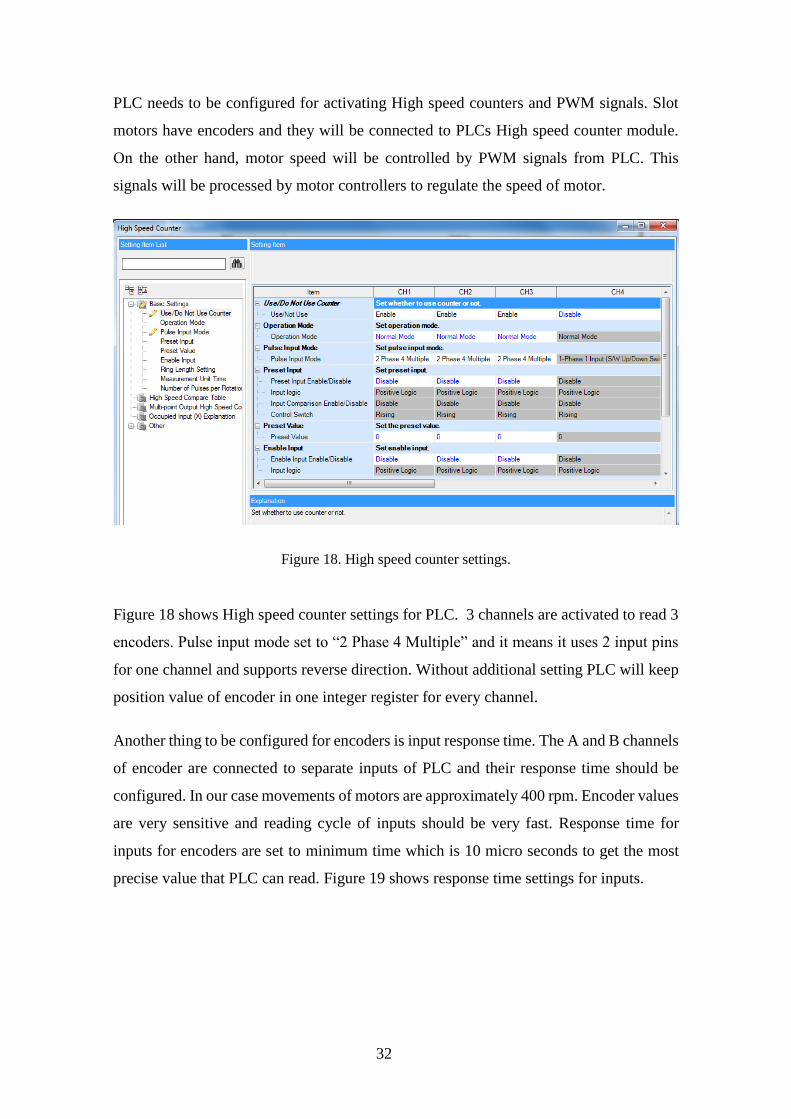
PLC needs to be configured for activating High speed counters and PWM signals Slot
motors have encoders and they will be connected to PLCs High speed counter module
On the other hand motor speed will be controlled by PWM signals from PLC This
signals will be processed by motor controllers to regulate the speed of motor
Figure 18 shows High speed counter settings for PLC 3 channels are activated to read 3
encoders Pulse input mode set to ldquo2 Phase 4 Multiplerdquo and it means it uses 2 input pins
for one channel and supports reverse direction Without additional setting PLC will keep
position value of encoder in one integer register for every channel
Another thing to be configured for encoders is input response time The A and B channels
of encoder are connected to separate inputs of PLC and their response time should be
configured In our case movements of motors are approximately 400 rpm Encoder values
are very sensitive and reading cycle of inputs should be very fast Response time for
inputs for encoders are set to minimum time which is 10 micro seconds to get the most
precise value that PLC can read Figure 19 shows response time settings for inputs
Figure 18 High speed counter settings
33
Next step is configuring PWM settings for output Output pins should be defined in
settings to activate and use them in program PWM cycle setting should be configured
also in settings page First 8 outputs support PWM outputs and 3 of them are needed to
use for 3 motors Cycle of PWM signals set to 100ms and motor controllers support this
cycle value Direction of motors are driven by another output pins Figure 20 shows PWM
setting page for output pins
Figure 19 Response time settings
Figure 20 PWM setting page
34
Flow diagram should be created firstly and it will be the basis of further implementation
According to the flow diagram skeleton of application will be created Specific functions
for Mitsubishi FX5U will be added step by step
System has 2 main loops - loading and unloading Ideal system will be focusing on
making all slots empty Unloading process has higher priority to reach his aim Even if
there is empty slot and ready product on picking place system is going to unload firstly
if there is a finished test in test station
To reach this target flow diagram is created to see big picture Figure 21 shows flow
diagram in general It contains single and multi-states Multi states will be explained later
It contains initialize state initializing blocks and then loop of load and unload processes
This diagram will be used also in section 52 for creating abstract Uppaal model of the
control program
35
Figure 21 General flow diagram
36
When PLC controller gets start input from HMI screen firstly its connections are getting
ready and registers from old sessions are clearing Connections have specific functions
To set the connection a protocol should be defined It is decided to use Modbus TCPIP
for communication between all modules and it should be configured in PLC side as a
predefined protocol
Figure 22 shows commands to open and close Ethernet connections To open a connection
ldquoSPSOCOPENrdquo function should be used It has 4 parameters U s1 s2 d This
instruction opens a connection specified in (s1) The set values used for the open
processing is selected in (s2) +0 The result of the ldquoSPSOCOPENrdquo instruction can be
checked with the completion device (d)+0 and (d)+1 To close a connection
ldquoSPSOCOPENrdquo function should be used It has same parameters as ldquoSPSOCOPENrdquo
This instruction closes a connection specified in (s1) (Disconnection of a connection)
The result of the ldquoSPSOCCLOSErdquo instruction can be checked with the completion
device (d) +0 and (d) +1
SD106800 is Boolean register that keeps status of first connection If it is true then
connection is alive SD106801 keeps status of second connection ldquostart_inputrdquo and
ldquostop_inputrdquo are directly connected to HMI screen buttons to get command from operator
to start or stop
To fetch holding registers over Modbus protocol protocol should be defined Figure 23
shows predefined protocol settings
Figure 22 Ethernet settings in ladder diagram
37
4 different Modbus protocols are defined in Figure 23 First protocol reads general outputs
from robot Second protocol sends command to robot These 2 protocols define 2-way
communication between PLC and robot Third protocol reads registers of status of slots
and errors from Test Station Fourth protocol reads special registers from Robot to detect
possible issues Figure 24 shows request packet setting of reading holding registers for
robot communication
Figure 23 Predefined protocol settings
Figure 24 Request packet setting
38
To request packet with Modbus TCPIP protocol inside of package ldquoTransaction IDrdquo
ldquoProtocol IDrdquo ldquoLengthrdquo ldquoModule IDrdquo ldquoFunction coderdquo ldquoHead holding register
numberrdquo and ldquoRead pointsrdquo should be define in correct order It is standard for Modbus
TCPIP protocol
Figure 25 shows response packet setting of reading holding registers for robot
communication To get response packet with Modbus TCPIP protocol inside of package
ldquoTransaction IDrdquo ldquoProtocol IDrdquo ldquoLengthrdquo ldquoModule IDrdquo ldquoFunction coderdquo ldquoNumber
of read bytesrdquo and ldquoDevice datardquo should be define in correct order This processes have
done for all predefined protocols
After all there is another problem PLC and robot can communicate over Modbus with
registers which are already defined in packet settings But problem is PLC and robot
doesnrsquot know anything about each other and they should have another protocol to
understand each other At that point upper level protocol comes in Figure 26 shows the
protocol diagram between PLC and Robot
Figure 25 Response packet setting
39
Figure 26 Protocol diagram between PLC and Robot
40
ldquo1YYZZrdquo is the format of command which PLC sends to robot 1 means action YY is the
first destination and ZZ is the last destination
Possible locations for YY
Command Location
01 PPP
31 Slot 1
32 Slot 2
33 Slot 3
Possible locations for ZZ
Command Location
31 Slot 1
32 Slot 2
33 Slot 3
61 Pass conveyor
62 Fail conveyor
63 Reject conveyor
To complete 1 cycle of command firstly PLC sends command in ldquo1YYZZrdquo format to
robot over register 128 When robot receives it immediately sends same command to
PLC over register 129 to prove that robot got the command properly On next state PLC
Table 1 YY variable
Table 2 ZZ variable
41
sends 0 to robot over register 128 When robot receives 0 it starts to execute command
When execution is finished robot sends 0 over register 129 to PLC to inform about the
termination of execution When PLC receives 0 cycle of process is completed This
sequence will be executed during state 1 and state 2 of PLC program
When PLC and robot are connected properly then PLC starts to initialize system It
checks sensors and motors to be sure if everything works fine Open and close sensors
for 3 slots motor movements open and close sensors for 3 slot handles and pneumatic
motor movements for slot handles should be checked during this initialization Also max
encoder value should be set dynamically during initialization
During initialization firstly slot is opening with constant speed slowly until getting the
signal from the end sensor of the slot and then it configures max encoder value Next it
opens slot handles by pneumatic motors until reach end sensor of handles Then it closes
slot handles when reaching the close sensor Finally slot closes when slot reaches the
close sensor of the slot This process repeats for all slots If there is a problem during
initialization then system stops and shows error message on the HMI screen
After initializing system goes in to loop which it begins the real processes State 999 is
the beginning of loop and after every successful cycle the system comes to state 999 In
state 999 system checks if there is something to unload PLC checks every slot status
from Test Station over Modbus communication If there is nothing to unload then system
goes to state 1000 In state 1000 PLC checks picking place sensor if there is something
to load If yes then PLC checks if there are any empty slots in Test station by Modbus
registers If yes it loads the product to empty slot else it goes back to state 999 and checks
if there is something to unload Basically in the idle mode PLC goes between state 999
and state 1000 Figure 27 shows state 999 in program And Figure 28 shows the state
1000 in program
42
Multi states represent details about unloading and loading states Figure 29 shows details
of multi states This diagram will help also to create Uppaal model in section 52 later
Figure 27 State 999 in ladder diagram
Figure 28 State 1000 in ladder diagram
43
State 1001 is executed if there is something to unload from slot 1 and according to result
it goes to deeper state If pass it goes to state 1010 if fail it goes to state 1020 and if reject
it goes to state 1030 In state 1010 it checks if M1500 is high for slot 1 If not it goes to
state 1500 to open the slot When slot movement is done M1500 Boolean register gets
true If M1500 is high then it checks if handles sensors are open If not it sets register
slot1_handle_open and when it reaches to end sensor it resets register
slot1_handle_open Then it goes to next step state 1
Figure 29 Details of multi states
44
State 1 and state 2 are communication states between PLC and robot In state one PLC
will send command 10131 according to protocol agreement and it means load from
picking place to slot 1 In state one PLC will expect to get same command back from
Robot in register 129 When PLC gets command back it will go to state 2 PLC will send
0 as command to Robot and PLC will wait for 0 as feedback from Robot Robot will load
electronic board from picking place to slot 1 and when it is done robot will send 0 to
PLC Then PLC will complete communication process successfully and goes to state
1011 This state is for closing slot PLC will check if slot1_handle_sensor is high If not
it will activate pneumatic motor to close handles When it reaches to sensor it will check
if M1501 is high If not it will go to state 1501 to close slot When close movement is
done it will go to state 1011 back and M1501 will be high
Once the cycle of unloading slot1 is completed it will go to state 999 to check if there is
unloading This process is same for every slots
44 Reliability experiments with the implemented system
Implementation is done and system correctness has to be validated by testing There are
several methods to test such systems but one of the important point is why and what
should be tested
One of the current project aims is to show that the system does not fail when operating
non-stop all day around When choosing the test method that point should be taken into
account Robot arm project team decided to make stress test on all system to prove the
robustness of software and hardware combination
Stress testing is a test method to force limits of newly developed application or newly
bought products to check the robustness of the system This method will show either
software and hardware related bugs reveal after the development increment
This test will include real scenario of using robot arm in production If it will be
successfully passed robot can be use in real production Explanation of test scenario
Firstly system will initialize itself after initialization operator will place a board to
product picking place Robot will take product from picking place and it places the
product to first empty slot In this case it will be first slot Actions should be like this for
cycle of one product in the following order opening slot opening handles picking board
45
from picking place eject board on slot closing handles closing slot test is starting test
finished open slot open handles picking board from slot eject board to correct conveyor
according to test result This cycle is expected cycle for a product but it has huge
dependencies on the working environment conditions hardware or software bugs
Summary of the first test run In this scenario target is testing 25 electronic board in a row
Automation test summary
RUN Slot Number
1 (ID) 2 (ID) 3 (ID)
1 10 PASS 9 PASS 7 Handle Error Drop Unit PASS
2 8 PASS 5 PASS
3 6 PASS
4 4 Test Fail Stucked in Conveyer
5 3
Dont fit on guiding Pins Push down manually Fail
2 PASS
6 4 Fail
7 10
Test Fail Stucked in Conveyer
1) Restart System 2) removed pins on all pallets from PTC side 3) replaced Samtec DIB saver PTC ($$$) 4) Conveyer Adjustments 5) 3rd slot drop issue fixing hellip 2 hours later
Table 3 First test run
46
8 2
Stucked inReady for Test Statushellip test PASS Fail on Conveyer (missing Target) Fixed by Said
1 PASS 5
Stucked in Ready for Test Statushellip Broken PTC in DUT ($$$)
9 4 PASS 3
Stucked inReady for Test Statushellip Broken PTC in DUT ($$$)
7 PASS
10 6 PASS
11 8 PASS 9 PASS
12 10 PASS
13 1 PASS 4 Stucked in Ready for Test Statushellip
14 2 PASS
15 7 Stucked in Ready for Test Statushellip
Andrey Called
16
The tests have been done for 25 electronic boards and summary is very bad Before testing
each unit had its own unit tests and there were not any major problems After stress tests
it is obvious that the system is not ready to go production During 8th run of slot 3 and 9th
run of slot 2 PTC connectors of boards got broken and it costs a lot Most of the errors
are related to mechanical parts and the test report summary should be analyzed carefully
to find which of the failures is related to PLC program and the algorithm
First run of slot 3 had a problem with slot handles and PLC program does not have error
handling mechanism for this problem and program crashed Root cause of the problem is
slot handle sensors for slot 3 Position of sensors are changed little bit and sensors cannot
detect correct position of handle motors It caused an endless movement command for
handle motors PLC expect to get sensor feedback when handles open until end the point
This bug should be solved
47
8th and 15th runs of slot 1 9th and 13th runs of slot 2 lastly 8th run of slot 3 have same
error ldquoStocked in ready for Test Statusrdquo It means test stations slot received electronic
board successfully and waiting slot to be closed to start testing Root cause of the problem
is a bug in the Test station but PLC program does not have error handling mechanism for
this problem as well and the program crashed PLC should raise an error message on HMI
side to inform operator about this status This feature should be added
Summary of second test run In this scenario target is testing 70 electronic boards in a row
Automation test summary
RUN Slot Number
1 (ID) 2 (ID) 3 (ID)
1 2 PASS 1 PASS 3 PASS
2 8 PASS
3 3 PASS 11 PASS
4 6 PASS 4 PASS
5 20 PASS 21 PASS
6 22 PASS 5 PASS
7 25 PASS 23 PASS 24 PASS
8 10 PASS
9 26 PASS 27 Stucked on Conveyer 48 PASS
10 28 PASS 40 PASS 29 Stucked on Conveyer
11 41 PASS Rejected (not registered)
42 PASS
12 44 PASS 43 PASS 45 PASS
13 47 PASS 46 PASS 12 PASS
14 13 PASS
15 14 Stucked on Conveyer
16 Stucked on Conveyer 17 PASS
16 Increasing the slope for Conveyer
17 47 PASS 18 Test plan didnt load
19 PASS
18 Call Andrey
19 19 PASS 47 Stucked on Conveyer 18
Rejected (not registered) Stucked on Conveyer
Table 4 Second test run
48
20 12 PASS 32 Stucked on Conveyer 31 PASS
21 33 PASS 35 PASS 34 PASS
22 15 PASS 37 PASS 36 PASS
23 38 PASS 39 PASS
24 33 PASS 32 Stucked on Conveyer
25 16 FAIL BS_PWR
26 50
Rejected (not registered) Stucked on Conveyer
33 Stucked on Conveyer 34 PASS
27 36 PASS 16 PASS 31 PASS
28
29
Second test is done after all known bugs are fixed Fixing the bugs took ca 1 week The
system was not operational during this time showing the importance of high quality
software validation Test summary shows there is a significant change between the first
test and the second test but still a lot known bugs were detected
16
64
9
11
F I R S T T E S T S E C O N D T E S T
TEST SUMMARY COMPARISON
Successful run Error
Figure 30 Test summary comparison
49
Second summary seems much better but all system is still not ready to work in production
full time Errors should be analyzed as in first test summary to get a clear picture Most
of the errors are ldquoStucked on conveyorrdquo and it is because of mechanical design problem
of conveyors Over 75 electronic board tests there was only one software error resulting
exception ldquoTest plan didnrsquot loadrdquo Root cause of the problem is because the Test Station
and PLC do not handle any error about this unexpected situation A solution is that PLC
should get loading status of test plan from Test Station and place it to reject conveyor by
directing Robot
After last tests still result is not good enough to use system in production Our target is
error free system and we cannot be sure about it by present test results Manual test
doesnrsquot give precise result there can be still bugs that we cannot predict According to
manual tests all bugs in system are fixed but there are some reports from production
operators that there are still unexpected behaviors Figure 31 shows number of reports
from operators for 1 week At this point there is a need to verify program and whole
system to find any kind of errors and bugs Proposed solution is model based testing to
create model of the system and test any kind of input output sequences to catch the errors
0
1
2
3
Day 1 Day 2 Day 3 Day 4 Day 5 Day 6 Day 7
Number of error reports
Error report
Figure 31 Number of error reports from production
50
5 Model Based Testing of Robot Arm Controller
51 Introduction to model based testing
Model-based testing automates the design of the test cases and the generation of the
traceability matrix More accurately instead of writing hundreds of test cases manually
an abstract model of the system under test is written by test designer and then the model-
based testing tool generates cases from that model The overall time of test design is
reduced besides variety of test suites from the same model can be generated simply by
using different test selection criteria The model-based testing process is divided into the
five main steps as shown in Figure 32
Figure 32 Model based testing process[19]
51
1 Modelling the SUT and its environment
2 Generating abstract tests from the model
3 Concretizing the abstract tests to make them executable
4 Executing the tests on the SUT
5 Analyzing results
In any testing process step 4 and 5 are a normal step they are even in manual testing
Step 3 is like the adaptor stage of keyword-based testing where the meaning of each
keyword is distinct The first two steps differentiate model-based testing from other type
of testing
The first step is to write a model of the system that is wanted to be tested It is called an
abstract model This is because it should be simpler and smaller than SUT itself It ought
to focus on only the key aspects that we would like to test and must omit many other
details of the SUT While writing the model it must be also annotated with requirements
to clearly specify the relationship between the requirements and the model
Afterwards it is desirable to use some tools to investigate that model is steady and has
the desired actions Most modeling systems deliver some verification tools some
interactive tools allow us to find out the model behavior and check whether it is what we
expect or not
The second step is to generate abstract tests of the model some test selection criteria must
be chosen in order to say which tests will be generated from the model because there are
an infinite number of test variations
The main output of this step is a set of abstract tests which are sequences of operations
from the model Since the model uses a simplified view of the SUT these abstract tests
lack some of the detail needed by the SUT and are not directly executable
The third step of model based testing is to transform the abstract tests into executable
concrete tests This may be done by a transformation tool which uses various templates
and mappings to translate each abstract test case into an executable test script
Alternatively it may be done by test adapter that wraps arounds the SUT and implements
52
each abstract operation in terms of the lower-level SUT facilities Either way the goal of
this step is to bridge the gap between the abstract tests and the concrete SUT by adding
in the low-level SUT details that were not mentioned in the abstract model
The fourth step is to execute the concrete tests on the system under test With online
model-based testing the tests will be executed as they are produced so the model-based
testing tool will manage the test execution process and record the results With offline
model-based testing we have just generated a set of concrete test scripts in some existing
language so we can continue to use our existing test execution tools and practices
The fifth step is to analyze the results of the test executions and take corrective action
For each test that reports a failure we must determine the fault that caused that failure
Again this is similar to the traditional test analysis process As usual when a test fails
we may find that it is due to a fault in the SUT or we may find that it is due to a fault in
the test case itself Since we are using model-based testing a fault in the test case must
be due to a fault in the adaptor code or in the model So this is another place where we
get feedback about the correctness of the model
To finish this section let us step back and take a more philosophical view of model-based
testing
It is always the case that test design is based on some kind of model of expected behavior
but with manual test design this model is usually just an informal mental model By
making the model explicit in a notation that can be used by model-based testing tools
we are able to generate tests automatically generate an arbitrary number of tests as well
as obtain more systematic coverage of the model These changes can increase both the
quality and quantity of our test suites
52 Constructing the test model
There are multiple different formalisms used for building conformance testing models
Uppaal Timed Automata (UTA) [20] is decided to be used in the light of the fact that the
53
formalism naturally supports state transitions and time and there exists a group of tools
that support model construction and verification
UTA used for the specification of the requirements are defined as a closed network of
extended timed automata that are called processes The processes are combined into a
single system by the parallel composition known from the process algebra CCS An
example of a system of two automata comprised of 3 locations and 2 transitions each is
given in Figure 33
The nodes of the automata are called locations and the directed edges transitions The
state of an automaton consists of its current location and assignments to all variables
including clocks The initial locations of the automata are graphically denoted by an
additional circle inside the location
Synchronous communication between the processes is by hand-shake synchronization
links that are called channels A channel relates a pair of edges labelled with symbols for
input actions denoted by eg chA and chB in Figure 33 and output actions denoted by
chA and chB where chA and chB are the names of the channels
In Figure 33 there is an example of a model that represents a synchronous remote
procedure call The calling process Process_i and the called process Process_j both
include three locations and two synchronized transitions Process_i initially at location
Start_i initiates the call by executing the send action chA that is synchronized with the
receive action chA in Process_j that is initially at location Start_j The location
Operation denotes the situation where Process_j computes the output y Once done the
control is returned to Process_i by the action chB
Figure 33 Example of a system of two Automata
54
The duration of the execution of the result is specified by the interval [lb ub] where the
upper bound ub is given by the invariant cllt=ub and the lower bound lb by the guard
condition clgt=lb of the transition OperationrarrStop_j The assignment cl=0 on the
transition Start_jrarrOperation ensures that the clock cl is reset when the control reaches
the location Operation The global variables x and y model the input and output arguments
of the remote procedure call and the computation itself is modelled by the function f(x)
defined in the declarations section of the Uppaal model
The inputs and outputs of the test system are modelled using channels labelled in a special
way described later Asynchronous communication between processes is modelled using
global variables accessible to all processes
Formally the Uppaal timed automata are defined as follows Let S denote a finite alphabet
of actions a b hellip and C a finite set of real-valued variables p q r denoting clocks A
guard is a conjunctive formula of atomic constraints of the form p ~ n for p ϵ C ~ϵ le ge
= gt lt and n ϵ N+ We use G(C) to denote the set of clock guards A timed automaton
A is a tuple N l0 E I where N is a finite set of locations (graphically denoted by nodes)
l0 ϵ N is the initial location E ϵ N x G(C) x sum x 2C x N is the set of edges (an edge is
denoted by an arc) and I N rarr G(C) assigns invariants to locations (here we restrict to
constraints in the form p le n or p lt n n ϵ N+ Without the loss of generality we assume
that guard conditions are in conjunctive form with conjuncts including besides clock
constraints also constraints on integer variables Similarly to clock conditions the
propositions on integer variables k are of the form k ~ n for n ϵ N ~ϵ le ge = gt lt For
the formal definition of Uppaal TA full semantics we refer the reader to [20]
According to flow diagram of Robot Arm Controller model of system can be created
Figure 21 general flow diagram and Figure 34 multi states diagram shows details of
system to create model
55
Figure 34 Multi-state diagram
56
State changes conditions and actions can be seen in diagrams First thing is creating
declarations of variables which will be used in models Figure 35 shows some part of
declarations
Sensors inputs outputs Modbus registers some registers which uses for feedback
variables and global variables for model are defined in declarations file Then model can
start to be created Figure 36 shows model of the main program
Figure 35 Declarations
57
Figure 36 Model of main program
58
Model has other processes synchronously works with it They are gclock Input_update
Input_update2 Motor1 Motor2 Robot and Test_station ldquogclockrdquo is global clock defined
5ms according to one cycle of PLC and input response sense Figure 37 shows gclock
process with TU which is time unit dependency for global clock
Input_update process is updating input array which is in use in model Source of inputs
is input_buffer array which user gives to Uppaal and it updates input array by global clock
to simulate system real time Figure 38 shows Input_update process
Ch1 is channel variable and global clock updates this channel by Ch1 action It triggers
Input_update process and other processes by Ch1 condition It provides synchronization
between all processes
Input_update2 process is updating Boolean variables which describe slot statuses of Test
station Source of process is ts_rx registers which is provided by user to Uppaal and
originally PLC fetches it over Modbus communication from Test station Figure 39 shows
Input_update2 process
Figure 37 gclock process
Figure 38 Input_update process
59
One of the most important point of the model is parameterized pattern In current flow
diagram there are some repetitive cycles for different slots and in the Uppaal model They
can be reduced to 1 action by using input parameters for processes Input_update2 process
automatically duplicate itself per every slots by parameter concrete values It gets id_t
parameter as input and it includes array of [012] This array is representation of slots
and every of them symbolize one of the slots According to input number it reproduces
variables which it uses in condition and actions On the other hand loading and unloading
flows are parameterized also In flow diagram every slot has separate action to unload
and load process In Uppaal model only one action is used for every slot and it checks
id_slot variable to process action for correct slot Lastly general inputs are parts of
parameterized pattern By one input array we read all inputs and process them by iterating
over the elements of array
Figure 39 Input_update2 process
60
53 Verifying the correctness of the test model
Model-checking is a promising method for the verification and validation of software
systems The method is applied to software requirement specification and design
specification and aims to increase the reliability and productivity from early stages of the
software development As the number of the success cases increases the method becomes
one of the basic tools for the use in the development of a wide variety of software [21]
Linear Temporal Logic (LTL) or Computation Tree Logic can be used for model
checking Uppaal verification tool supports CTL commands and we will use CTL for
verification CTL is propositional temporal logic with explicit quantification over
possible futures Figure 40 shows sample of tree of computation
Timed Computation Tree Logic (TCTL) is sufficiently expressive to allow for the
formulation of an important set of real-time system properties Formulae in TCTL are
either state or path formulae TCTL extends CTL with atomic clock the set of clocks in
the timed automaton under consideration
Figure 40 Sample of tree of computation
61
Figure 41 shows some examples how the TCTL formulas are interpreted on a simple
computation tree that represents traces of an hypothetical model M Starting from an
initial location a
Altgtϕ (inevitable) true if local condition ϕ (eg valid in yellow locations) is reachable in
all execution paths
Eltgtϕ (possible) true if local condition ϕ (eg valid in a red location) is reachable in at
least one execution path
A[]ϕ (always) is true if local condition ϕ holds in all locations of all execution paths not
valid for given example assuming the initial location is a
ϕ1048576Ψ (leads-to) is true if all paths involving a location where condition ϕ is valid include
thereafter a location where is valid
The TCTL model-checking algorithm with UPTA is built upon the method of model
checking TA Regarding to algorithm proper queries should be created to execute model
checking First we will check deadlocks in the model System shouldnrsquot have any
deadlocks Following query will provide us result of verification if there is any deadlock
in model
A[] not deadlock
Figure 41 Simple computation tree
62
Model is always in progress during its execution and even if there is not any deadlock
varication wouldnrsquot finish until manually stop it Because verification tool will check
deadlocks over infinite time horizon of the model it will stop only when this horizon is
set or verification is manually stopped Figure 42 shows verification settings screen
during deadlock verification
Another method is using time bounded deadlock check The query is shown below
Eltgt gclk lt Const imply deadlock
Additional clock gclk used to check time of verification and Const is time bound of the
verification This query checks if there is any deadlock during defined time bound and
Const defined as 500 cycle Figure 43 shows time bounded deadlock verification result
This query proves that there isnrsquot any deadlock in model and then other properties of the
model can be checked
Figure 42 Deadlock verification
Figure 43 Time bounded deadlock verification
63
Next queries will check specific states and conditions to verify model if itrsquos reaching both
conditions in some cases Following query will provide us result of verification if model
can go state 20 and TS slot 1 status should be ldquoreadyrdquo
Eltgt programs20 ampamp slot_ready[1]
State 20 has task to close slots and slot handles after loading board process And if slot 1
is ready on same time it means system is closing slot 1 after loading process Figure 44
shows verification result of query
Figure 44 Verification of first query
64
As seen in Figure 44 the query property is satisfied successfully and model can reach
this conditions simultaneously Next query will check if system can reach state 2 and
receive command 10132 from Robot
Eltgt programs2 ampamp robot_rx==10132
State 2 communicates with Robot and Robot should send back same command what PLC
sends to it so verification tool will check after PLC sends 10132 command if robot will
send it back Figure 45 shows verification result of query
As seen in Figure 45 the query property is satisfied successfully by model execution
Next query will check if system reaches state 2002 and slot handles activates for slot 3
Eltgt programs2002 ampamp slot_handle_close[2]==1
State 2002 is part of the initialization and responsible for closing slot and handles In
this state verification tool will check if slot handles for slot 3 closes correctly during
initialization Figure 46 shows verification result of query
Figure 45 Verification of second query
65
Firstly ldquoEltgt programs2002 ampamp slot_handle_close[2]==1rdquo query executed accidently
and it raised verification error Problem is 3rd slot is ldquoslot_handle_close[2]rdquo and
ldquoslot_handle_close[3]rdquo is out of range Array expects range of [012] Then with
correct query property satisfied successfully
Other properties can be verified as well when the model is refined during program
updates But for current model the most critical conditions are verified with Uppaal
verification tool as demonstrated above
54 Generating tests from the verified test model
Model-based testing is testing on a model that describes how the system is required to
behave The model built in a suitable machine interpretable formalism can be used to
automatically generate the test cases either offline or online and can also be used as an
oracle that checks if the SUT passes the tests Offline test generation means that tests are
generated before test execution and executed when needed In the case of online test
generation the model is executed in lock step with the IUT The communication between
the Tester and the SUT involves controllable inputs of the SUT and observable outputs
of the SUT For example we can command the robot to move its manipulator to specified
position and we can observe if and when the robot achieves the goal
There are multiple different formalisms used for building models of the requirements
Our choice is Uppaal timed automata (TA) [20] because the formalism naturally supports
state transitions and time and there exists the Uppaal Tron [22] tool that supports online
model-based testing The overall test setup used in the context of model-based testing
with Uppaal Tron as the test engine and dTron as the adapter generation framework is
given in Figure 47 The model contains the specifications of the SUT and the
environment The adapter is responsible for translating abstract model inputs and outputs
to program inputs and outputs The dTron layer allows the adapter to be distributed across
Figure 46 Verification of third query
66
multiple computers while ensuring that time progress in distributed tester models still
stays valid
The test configuration used in this work consists of test execution environment dTron and
one or many test adapters that transform abstract inputoutput symbols of the model to
inputoutput data of the robot The setup is outlined in Fig 1 Uppaal Tron is used as a
primary test execution engine Uppaal Tron simulates interactions between the SUT and
its environment by having two model components ndash the environment and the
implementation model The interactions between these component models are monitored
during model execution When the environment model initiates an input action i Tron
triggers input data generation in the adapter and the actual test data is written to the robot
interface In response to that the robot software produces output data that is transformed
back to model output o Thereafter the equivalence between the output returned and the
output o specified in the model is checked The run continues if there is no conformance
violation ie exists an enabled transition in the model with parameters equivalent to those
passed by the robot In addition to inputoutput conformance Uppaal Tron also checks
for timing conformance We refer the reader to [20] for the details on that relation
Generation of test runs
a) In offline test generation Uppaal model checker generates symbolic test sequences
that witness satisfaction of some property to be covered by given test case These
sequences (they include test inputs and expected outputs) are executed by test
execution environment egUppaal Tron or DTRON
Figure 47 Test setup with Uppaal Tron [22]
67
b) Alternatively for online Conformance testing random walk strategy can be used
on SUT model where the test stimuli are selected on-the-fly and the reactions
from SUT are compared with those predicted by SUT model According to the
Figure 47 an adapter is needed to convert symbolic test inputs and outputs to the
executable ones Online conformance testing suites for duration tests and is
feasible for regression testing
The test adapters for given case study can be created with proper input - output
connections between PLC and PC which runs Uppaal Tron The test passes if during
the test run the conformance relation between the test model and real behavior is not
violated Otherwise test fail is reported and the diagnostic trace exposed by Tron for
error analysis
68
6 Summary
The thesis was focusing on development model checking based PLC software testing
solution The motivation was derived from the actual needs of quicker debug of complex
PLC controlled systems
Certain industrial robot applications were described including original factory automation
solution developed by the author of thesis This particular robot system contains of Test
Station Universal Robots UR10 Mitsubishi FX5U PLC controller sensors and motors
Implementation of PLC software is described and it gives specific proprieties and
commands for Mitsubishi FX5U type PLC Test station Robot and PLC had stress test in
whole system and results showed there is a need for new solution to debug and test PLC
software
Model checking with Uppaal tool was performed Accent of work is combining formal
methods allowing to prove correctness of design against both functional and
dependability requirements The given approach is illustrated in Uppaal model It
contains PLC software and simulation processes of Test station and Robot The
correctness of the control system is successfully verified using Uppaal verification tool
Further work should focus on connecting Uppaal verification tool to real hardware For
that approach Uppaal Tron extension is needed for allowing Uppaal model to use with
other environments Additionally physical adapter is needed to connect input outputs of
the PLC controller to PC This adapter can be build according to PLC specifications With
Uppaal Tron verification can be done by comparison between Uppaal model and real-
time PLC input outputs
69
References
[1] J Bloem ldquoThe Fourth Industrial Revolution Things to Tighten the Link Between
it and otrdquo VINT Res Rep pp 1ndash39 2014
[2] M Newman ldquoSoftware errors cost US economy $595 billion annuallyrdquo NIST
Assesses Tech Needs Ind to Improv 2002
[3] ldquoAdvantech factory automationrdquo [Online] Available
httpwwwrrfloodycomAdvantechFAhtml [Accessed 15-Mar-2017]
[4] ldquoLadder Logic Examples and PLC Programming Examplesrdquo [Online] Available
httpwwwplcacademycomladder-logic-examples [Accessed 15-Mar-2017]
[5] D Darvas B Fernaacutendez Adiego A Voumlroumls T Bartha E Blanco Vintildeuela and V
M Gonzaacutelez Suaacuterez ldquoFormal Verification of Complex Properties on PLC
Programsrdquo Springer Berlin Heidelberg 2014 pp 284ndash299
[6] ldquoIndustrial robots What are the different typesrdquo [Online] Available
httpblogrobotiqcombid63528what-are-the-different-types-of-industrial-
robots [Accessed 19-Mar-2017]
[7] ldquoMaterial Handling Robotrdquo [Online] Available
httpswwwrobotscomapplicationsmaterial-handling [Accessed 19-Mar-
2017]
[8] K Hee ldquoObject-Oriented Modeling Simulation and Automatic Generation of
PLC Ladder Logicrdquo in Programmable Logic Controller InTech 2010
[9] ldquoUniversal Robotics UR10rdquo [Online] Available
httpfabcbamiteducontenttoolsuniversal_robot_armsindexhtml [Accessed
23-Apr-2017]
[10] ldquoFX5U-64MT-ESS | Mitsubishi FX5U FX5U-64MT-ESSrdquo [Online] Available
httpwww999mitsubishicommitsubishi-fx5u-fx5u-64mt-ess [Accessed 15-
Mar-2017]
[11] ldquoELEKTRIK-ELEKTRONIK TEKNOLOJISI PLC PROGRAMLAMA
TEKNIKLERI 523EO0053rdquo 2011
[12] S S Peng and M C Zhou ldquoLadder Diagram and Petri-Net-Based Discrete-
Event Control Design Methodsrdquo IEEE Trans Syst Man Cybern Part C
(Applications Rev vol 34 no 4 pp 523ndash531 Nov 2004
[13] K-H John and M Tiegelkamp IEC 61131-3 Programming industrial
automation systems concepts and programming languages requirements for
programming systems decision-making aids Springer 2010
[14] B Rexroth Corporation ldquoUnderstanding the IEC61131-3 Programming
Languagesrdquo
[15] Z Aspar M Khalil-Hani and N Shaikh-Husin ldquoDeadlock detection and
avoidance using Signal Interpreted Petri Netsrdquo in 2012 IEEE International
Conference on Circuits and Systems (ICCAS) 2012 pp 150ndash155
[16] J Martins C Lima H Martiacutenez and A Grau ldquoA MatlabSimulink framework
for PLC controlled processesrdquo
[17] B F Adiego D Darvas J C Tournier E B Vintildeuela and V M Gonzaacutelez
Suaacuterez ldquoBringing automated model checking to plc program development - A
70
CERN case studyrdquo in Advances in the Astronautical Sciences 2014 vol 12 pp
394ndash399
[18] ldquoAksIMTM supports Universal Robots for smart factory automationrdquo [Online]
Available httpwwwrenishawcomenaksim-supports-universal-robots-for-
smart-factory-automation-factory-automation--40903 [Accessed 15-Mar-2017]
[19] M Utting and B Legeard Practical model-based testing a tools approach
Morgan Kaufmann Publishers 2006
[20] J Bengtsson and W Yi ldquoTimed Automata Semantics Algorithms and Toolsrdquo
Springer Berlin Heidelberg 2004 pp 87ndash124
[21] S Nakajima ldquoModel-Checking Verification for Reliable Web Servicerdquo
[22] K G Larsen M Mikucionis B Nielsen and A Skou ldquoTesting Real-Time
Embedded Software using UPPAAL-TRON An Industrial Case Studyrdquo

Tallinn 2017
TALLINNA TEHNIKAUumlLIKOOL
Infotehnoloogia teaduskond
Eren Cizmecioglu 146675IVEM
MUDELIPOtildeHINE PLC
TOumlOumlSTUSTARKVARA TESTIMINE
Magistritoumlouml
Juhendaja
Kaasjuhendaja
Alar Kuusik
PhD
Juumlri Vain
PhD
3
Authorrsquos declaration of originality
I hereby certify that I am the sole author of this thesis All the used materials references
to the literature and the work of others have been referred to This thesis has not been
presented for examination anywhere else
Author Eren Cizmecioglu
15052017
4
Abstract
This thesis describes authorrsquos developments and engineering activities in the field of
model based testing of PLC-based automation systems The work describes limitations
of PLC operation its software debugging complexity and time consumption which led
to the needs of developing newer and faster methods of PLC software testing The
particular developments were strongly relying on a real factory robot arm controller
project Its description and implementation is given to understand the model based testing
algorithm and the process A model of the robot arm system was developed within the
Uppaal software framework and system verification was completed the with Uppaal
verification tool
This thesis is written in English and is 57 pages long including 6 chapters 47 figures and
4 tables
5
Annotatsioon
Mudelipotildehine PLC Toumloumlstustarkvara Testimine
Kaumlesolev lotildeputoumlouml kirjeldab autori arendusi ja inseneritegevust programmeeritavatel
toumloumlstuskontrolleritel ehk PLC-del potildehinevate automaatikasuumlsteemide mudelipotildehise
testimise vallas Toumlouml kirjeldab PLC rakendamise ja tarkvara silumisega seotud piiranguid
ning sellest tulenevat ajamahukust mis viis vajaduseni vaumllja toumloumltada uuemad ja kiiremad
meetodid PLC tarkvara testimiseks Konkreetsed arendused tuginesid olulisel maumlaumlral
reaalsele tehase robotkaumle juhtimiskontrolleri projektile Selle kirjeldus ja teostus on toumloumls
esitatud selgitamaks mudelipotildehise testimine algoritmi ja kaumliku Robotkaumle suumlsteemi mudel
toumloumltati vaumllja Uppaal tarkvararaamistikus ja suumlsteemi verifitseerimine teostati Uppaali
verifitseerimistoumloumlriistaga
Toumlouml on kirjutatud inglise keele 57 lehekuumlljel sisaldab 6 peatuumlkki 47 joonist ja 4 tabelit
6
List of abbreviations and terms
DPI
PLC
SUT
TA
TCTL
TS
Dots per inch
Programmable Logic Controller
System Under Test
Timed Automata
Timed Computation Tree Logic
Test Station
TTU
UPTA
Tallinn University of Technology
Uppaal Timed Automata
7
Table of contents
Authorrsquos declaration of originality 3
Abstract 4
Annotatsioon Mudelipotildehine PLC Toumloumlstustarkvara Testimine 5
List of abbreviations and terms 6
Table of contents 7
List of figures 9
List of tables 11
1 Introduction 12
11 Problem statement 12
12 Implementation of factory automation systems 12
2 Industrial robots 15
21 Use examples of industrial robots 15
22 Palletizing robot of the particular automation solution 18
3 Programmable Logic Controllers and their properties 20
31 Programming logic and language types in PLC 21
32 PLC program software languages 23
33 Specific limitations of PLC programming 25
34 State-of-the-art methods to reduce PLC software errors 26
4 Implementation and testing of a PLC controlled production cell 28
41 Description of production testing cell 28
42 PLC Controller functions 31
43 PLC software implementation 31
44 Reliability experiments with the implemented system 44
5 Model Based Testing of Robot Arm Controller 50
51 Introduction to model based testing 50
52 Constructing the test model 52
53 Verifying the correctness of the test model 60
54 Generating tests from the verified test model 65
6 Summary 68
8
References 69
9
List of figures
Figure 1 Production Automation [3] 13
Figure 2 Example fragment of a ladder program [4] 14
Figure 3 Painting robot in operation [6] 15
Figure 4 Assembly robots in car industry [6] 16
Figure 5 Welding robot in operation [6] 16
Figure 6 Material handling robot [6] 17
Figure 7 Palletizing robot in operation [6] 18
Figure 8 A set up of Universal Robot UR10s [9] 19
Figure 9 Mitsubishi FX5U [10] 20
Figure 10 Scan cycle of PLC 22
Figure 11 Example of Ladder Diagram [11] 24
Figure 12 Example of Function block diagram [11] 24
Figure 13 Example of Statement list [11] 25
Figure 14 Universal Robots UR10 [18] 29
Figure 15 System relationship 29
Figure 16 Test station 30
Figure 17 GX Works3 sample screen 31
Figure 18 High speed counter settings 32
Figure 19 Response time settings 33
Figure 20 PWM setting page 33
Figure 21 General flow diagram 35
Figure 22 Ethernet settings in ladder diagram 36
Figure 23 Predefined protocol settings 37
Figure 24 Request packet setting 37
Figure 25 Response packet setting 38
Figure 26 Protocol diagram between PLC and Robot 39
Figure 27 State 999 in ladder diagram 42
Figure 28 State 1000 in ladder diagram 42
Figure 29 Details of multi states 43
10
Figure 30 Test summary comparison 48
Figure 31 Number of error reports from production 49
Figure 32 Model based testing process[19] 50
Figure 33 Example of a system of two Automata 53
Figure 34 Multi-state diagram 55
Figure 35 Declarations 56
Figure 36 Model of main program 57
Figure 37 gclock process 58
Figure 38 Input_update process 58
Figure 39 Input_update2 process 59
Figure 40 Sample of tree of computation 60
Figure 41 Simple computation tree 61
Figure 42 Deadlock verification 62
Figure 43 Time bounded deadlock verification 62
Figure 44 Verification of first query 63
Figure 45 Verification of second query 64
Figure 46 Verification of third query 65
Figure 47 Test setup with Uppaal Tron [22] 66
11
List of tables
Table 1 YY variable 40
Table 2 ZZ variable 40
Table 3 First test run 45
Table 4 Second test run 47
12
1 Introduction
11 Problem statement
The fourth industrial revolution is believed to significantly increase the productivity of
factories and industry in general [1] The essential requirement for Industry 4x is higher
level of integration of factory automation with other part of production chain including
logistics resource management and quality assurance There is also pressure to lower
manufacturing costs improve production quality and flexibility In general reducing the
amount of human labor improves the production quality and lowers the production costs
today especially in machinery and electronics production However production
flexibility requirements add challenges to factory automation software development
Because of massive use of robots shorter manufacturing cycles and simultaneous
manufacturing of several products an error free software development and feasible
solutions for validating software modification are of high demand
According to NIST report improving software testing quality would reduce the error
caused economic losses by 13 [2] Today the majority of industrial manufacturing
equipment is controlled by programmable logic controllers (PLCs) Methodologies for
PLC software testing are rather weakly developed and used which makes fast software
verification a complex task Current thesis focusses on the development of PLC software
testing methods for electronic manufacturing industry that will simplify releasing
software modifications and software debugging process An initial target was electronics
production testing cell consisting of an arm robot conveyors and a test station
12 Implementation of factory automation systems
Today the majority of factory automation systems rely on PLCs As shown in Figure 1
PLCs are used in production packaging logistics and warehousing
13
There are many factory automation system providers in the market as Festo ABB
Mitsubishi and others Typically these systems also include industrial robots Robots can
replace physical workers in almost every part of the modern production line For example
screwing picking and placing transporting goods etc It is possible to find different kind
of ready-made solutions in the market but in some cases more flexibly controlled and
adjustable solutions are needed This was the motivation for developing the custom-made
ldquoAutomated robot armrdquo system for an electronics factory Importance of more advanced
PLC software debugging methods came out in practice during the implementation of the
real robot arm system which is more complex than traditional PLC controlled solutions
In general it is easier to create robust and error free automated system controlled with
just one PLC device In the particular system PLC has to operate jointly with a PC based
Test Station and Arm Robot having its own motion controller
PLC is a relevant and robust control solution for industrial applications but its specific
problem is that the programs have to be encoded using low-level ladder diagram shown
in Figure 2 It is very hard to debug ladder program code which is quite different from
high level programming languages as C C++ Java etc
Figure 1 Production Automation [3]
14
It is hard to detect software errors and possible run-time problems if proper debugging is
impossible Especially in a case when different devices with own controller are integrated
into one system
One proposed solution is model based testing on PLC software suggested by Darvas et
al [5] Model of the system will be created and this model will be tested over the complete
state space under possible input and output conditions At the end it should be possible to
verify the software running on real hardware
Figure 2 Example fragment of a ladder program [4]
15
2 Industrial robots
21 Use examples of industrial robots
Type of work is defining the application that the robot is intended to do Different
requirements are needed for different applications For example an assembly robot will
have narrow workspace but will be quick and precise Then again a painting robot will
have a small workspace however will require wide angle and range of movement
Depending upon the objective application the robot will have a particular kind of
movement linkage measurement control law and program
Industrial robots are the core components for the modern production packaging and
assembly Some examples of industrial robots used in manufacturing process are
following
Painting robot
Painting robots have been used for long years in automotive field from the first hydraulic
versions to the latest electronic models Painting robots mostly have five or six axis
movement three for the base movements and up to three for implement orientation [6]
Figure 3 Painting robot in operation [6]
16
Assembly robot
In the manufacturing world assembly robots are widely used [6] Assembly robots
increase the quality and production speed They also save workers from boring and dull
assembly line work
Welding robot
Robot welding is commonly used for resistance spot welding and arc welding in high
production applications such as the automotive industry [6]
Figure 4 Assembly robots in car industry [6]
Figure 5 Welding robot in operation [6]
17
Material handling robot
Material handling robots can automate some of the most tedious dull and unsafe tasks
in a production line [7] They are used for task that workers cannot handle easily as
carrying heavy load in couple of seconds
Palletizing robot
Palletizing robots can be seen in numerous ventures including sustenance preparing
assembling and transporting Robots perform stacking and emptying parts boxes or
different things from or to pallets
Different end-of-arm-tooling styles permit adaptability of various sorts of robot
palletization Sack grippers include a thing and bolster it on the base while suction and
attractive grippers commonly handle more furrowed things and hold them from the top
With this robots you can expand the consistency of your stacking and emptying
processes
Figure 6 Material handling robot [6]
18
22 Palletizing robot of the particular automation solution
In this particular factory use case palletizing robot has to carry electronic boards between
picking place slots of Test Station and output conveyors Important requirements to the
particular Robot were following it should support any suitable communication protocol
to connect and sendreceive data from an external controller (PLC) device should handle
objects with weight of at least 9 kg the number of operational degrees of freedom is 180
Regarding the communication standards of the Modbus protocol CC-link and Profinet as
are widely used in industrial automation applications Modbus is one preferred protocol
because it is open and it can be easily used with products of different vendors as Siemens
Mitsubishi Delta Omron etc Modbus protocol has 2 different substandard Modbus
RTU and Modbus TCPIP are different protocols for different media solutions Modbus
RTU uses serial connection over RS485 or RS232 Nowadays it is not popular as any
more Modbus TCPIP is using Ethernet connection and conventional RJ45 cable
connectivity between devices Because Modbus TCPIP supports more features and
robust connectivity it is a good choice for robot interfacing TCPIP protocol is important
because the server-client connections can be established with many devices on same time
to implement wider network and bigger system There are several models of arm robots
directly supporting Modbus TCPIP communication
For this particular automation project Universal Robot UR10 [8] model was chosen This
is a collaborative type robot and it supports Modbus and Profinet communication
protocols It has own programming environment and over shared register space area it
Figure 7 Palletizing robot in operation [6]
19
can take orders from another device in particular case from the PLC controller Figure 8
shows Universal Robot UR10 model The robot has own Linux based operating system
and programming interface to perform movements from a way point to another way point
create and modify operations of special peripherals as gripper to vacuum boards Whole
system setup and operation is described in Chapter 41
Figure 8 A set up of Universal Robot UR10s [9]
20
3 Programmable Logic Controllers and their properties
Programmable logic controllers are widely used in industrial automation There are many
companies manufacturing PLCs Allan BradleyRockwell Mitsubishi Schneider
Electric Siemens and others Also for this particular industrial automation project it was
decided to use a PLC because it can be easily connected to the sensors motors and other
24V compliant inputs and outputs On the other hand PLCs have special built-in modules
as high speed counters and communications interfaces
Siemens and Mitsubishi devices were considered for this particular automation project
Based on comparison of price versus features stability and support Mitsubishi FX5U
that is shown in the Figure 9 was chosen Particular PLC has 64 input ndash output terminals
which is enough for this system FX5U supports Modbus protocol being it is able to
communicate with UR10 robot
Figure 9 Mitsubishi FX5U [10]
21
31 Programming logic and language types in PLC
Program processing logic in PLC
PLC controllers are based on conventional microprocessors but their programming logic
is different due to industrial needs A microcontroller has a standard software language
support as embedded C or C++ and it executes a program line by line It cannot continue
with a new command before finishing execution of a current one It is a bit different for
PLC controllers All lines of the program are working in parallel and without any
dependency from each other in continuous scan cycle
Signals from the sensor button limit switch etc connected to the inputs are read and
stored in the input memory and the control program commands loaded in the program
memory of the PLC are executed in sequence The results obtained according to the input
variables are transferred to the output memory
The information in the output memory is transferred to the outputs on the shelf to execute
the work elements connected to the PLC outputs and inputs are read again The time taken
for these operations to take place is called a scan cycle The scan cycle repeats
continuously until the power of the PLC is turned off or until it is set to the STOP position
The duration of a scan cycle depends on the PLC running speed and the length of the
control program Typically the duration of a scan cycle is between 3 ms and 10 ms If
this loop time is too long very short time input spikes may not be detected
22
Linear programming logic
Linear programming means that all commands are written in the same program area The
command is executed according to the order of writing and all commands goes to process
during a cycle In this programming format the program is organized in main program
and sub program format Subprograms are either written in the program end command
(such as END MEND) of the main program or in a special field
In linear programming when a subprogram is invoked from a subprogram constructions
can be used However this programming is usually not preferred as it compromises the
design and monitoring of the control system
The commands written in the main program can usually be used in the subprograms In
the new version software STEP 7 - Micro WIN V30 developed for the programming
of Siemens S7-200 PLC class the subprograms are written in the reserved areas for these
subprograms and therefore the main program end command (MEND) Program command
(RET) interrupt subprogram command (RETI) is not used [11] Again this software has
improved the features that allow the sub-program structured usage to work properly for
Figure 10 Scan cycle of PLC
23
the new generation processors of S7-200 class (CPU 221 CPU 222 CPU 224 and CPU
226) [11]
Linear programming is usually used in small applications and low capable systems
Advantages is you will program your application in one page without any dependency of
other code or functions and in small application it will be clear and easier way to reach
your target On the other hand it has disadvantages like in huge applications it will give
a confusing and misleading picture because of complexity of application
Structured programming logic
Structured programming is divided into functions of large-scale programs is a form of
programming that uses only one program part for tasks that provide same functionality
The GX Works3 software which is used to program the FX class PLCs produced by
Mitsubishi is suitable for both linear and structured programming For example the GX
Works3 language program contains program parts that provide various functions of
organization program and function blocks All program blocks can be thought of as
subprograms Special sub-organizational blocks are also used for cutting sub-programs
The system program executes the organizational blocks The jump commands written to
the organization block determine which blocks to execute in a program cycle
Structured programming is suitable for huge applications It gave advantages as modules
can be re-used many times thus it saves time reduces complexity and increase reliability
32 PLC program software languages
Ladder diagram (LD)
Ladder diagram [12] is a graphical programming method similar to implementing
conventional electric control circuits of relays and contactors The ladder plan has a
programming logic which is easy to come to the user in the form of energy symbol which
flows through the contacts from an energy source like the electric circuits The vertical
line on the left side of the ladder program shows the energy source Open contacts do not
allow for energy flow when closed contacts allow energy flow The ladder plan method
is suitable for those who have more electricity training and beginners Figure 11 shows a
program example written with ladder diagram method
24
Function block diagram (FBD)
The FBD [13] method is a programming scheme based on the use of logic gates and
providing a semantic representation The logic symbols used here are shown in boxes
The symbols have input signals on the left side and output signals on the right side This
method can be used more easily with digital electronics knowledge Figure 12 shows the
program example written with FBD method
Statement list (STL)
In the STL [13] method commands with the same function according to the type and
brand of the PLC but with small differences in the software form are used A command
consists of Mnemonic specifying the operation to be performed and operands indicating
Figure 11 Example of Ladder Diagram [11]
Figure 12 Example of Function block diagram [11]
25
the memory areas on which the operation is performed This method offers a wide range
of programming possibilities since the instrument is the closest to the machine code The
STL method addresses those parts that are prone to computer technology
Programs written with STL FBD and LADDER methods can be converted to each others
styles if they are written and compiled without errors Figure 13 shows the program
example written with STL method
Differences between programming languages of PLC can be concluded as follows LD is
based on relay logic and FBD is based on electronic gates Difference is you can use
function block with FBD and it will reduce of complexity in huge applications STL is
different method than others and it uses text as programming method STL doesnrsquot
support monitoring on Mitsubishi and old Siemens software environments it is making
debug harder than usual
33 Specific limitations of PLC programming
PLC controllers can be programmed with different ways It gives flexibility to choose
most comfort way to programmer Although PLCrsquos have high level of success in industry
they have also weak points and problems on programming and debugging part
IEC 61131-3 is standard of languages for PLCs published by International
Electrotechnical Commission (IEC) The IEC is an organization that prepares and
publishes international standards for all electrical electronic and related technologies
including controllers [14] This standard defines common languages for PLCs and PLC
Figure 13 Example of Statement list [11]
26
producers are following this standard Although there is a well-known standard for
programming PLC programs cannot transfer to another PLC which is different brand
This problem will be seen even between different models of same brand PLC controllers
has various function and features as built in modules for different type of models Every
brands have their own programming environment and accordingly programs are not
interchangeable among to vendors and models Solutions of similar problems for different
developers can be found easily but solution wouldnrsquot be applicable for every PLCrsquos
On the other hand Ladder diagrams are difficult to read Troubleshoot is very important
part of PLC maintenance and Ladder diagrams are hard to find root cause of problems
Most of the PLC models support monitoring future to maintenance systems but any of
them doesnrsquot support real time debugging as high level programming languages C++
Java etc Implementation is becoming increasingly complex because of short design
cycles and product specification [15] Accordingly detecting bugs errors and unstable
parts in program takes very long time and getting to be harder
34 State-of-the-art methods to reduce PLC software errors
Currently there are no widely adopted systematic logic code development methodologies
to deal with PLC based control systems [8] So the control logic design phase is usually
omitted in current PLC programming development life cycle though it is essential to
reduce logic errors in an earlier stage of automation projects before the implementation
of control logic Moreover fast customer requirement changes require flexibility of
manufacturing system To deal with these frequent configuration changes of modern
manufacturing systems it is required that logic code can be generated automatically from
the design results without considering complicated control behavior [8]
To reach error-free ladder code it is also essential to validate the designed control logic
of an automated manufacturing systems in an efficient method Among several validation
ways simulation methods are widely used as a result of mathematical formalisms have a
haul of solution area explosion because the size of system will increase However since
current simulation ways have primarily targeted on the general performance analysis of
producing systems like factory layouts resource utilization and throughput time They
have limitations with respect to the modeling capabilities of detail logic for the
inputoutput signal-level management of automated manufacturing systems [8]
27
Therefore current PLC ladder programming practices need a more integrated way to
design simulate and generate the ladder control logic
There are some solutions for improving the quality of PLC programs like scale models
simulation tools Human Machine Interfaces (HMI) or Supervisory Control and Data
Acquisition (SCADA) systems [16] Several testing methods are analyzed by Adiego et
al [17] The use of scale models of real processes is extremely costly and tough to adapt
to completely different processes There is no doubt that this is the most advanced way to
teach PLC controlled process permitting project testing in an nearly real environment
but the price and complexity usually prohibits its use The use of leds and switches sets
is very confusing end uninteresting This approach solely valid once small processes are
thought of severely reduces the motivation Some HMI and SCADA systems allow this
feature however there are very pricy not supposed for this purpose and frequently take
into account property protocols
28
4 Implementation and testing of a PLC controlled production
cell
The following chapter describes implementation and testing of a particular robotized
production testing cell at an electronics factory The system is more complex than
conventional PLC control systems because it contains other active controllers Therefore
the PLC software debug turned out to be a complex task giving a motivation for Model
Checking based software testing for the further similar applications
41 Description of production testing cell
The production test system (cell) consists of three parts Test Station (TS) Robot and
Controller Controller is a Mitsubishi FX type PLC that handles synchronization of other
controllers collects sensor readings executes all actuators except robot arm ones During
the normal operation the system has to be able to swap electronic boards in one hour each
full operation cycle should take more than 40 seconds Therefore we can say that PLC
operates as a system Controller
Significance of this robot arm is that there are electronic boards that should be tested
immediately after their composition During this test Robot arm must be communicating
with test station in real time This communication is important because it can cause wrong
results and synchronization of the test station and robot is crucial activity Figure 14
shows Universal Robot UR10 which is controlled by PLC
29
Figure 15 shows data connections between modules implemented as Modbus TCPIP
connections and connection of sensors and actuators
Figure 14 Universal Robots UR10 [18]
Figure 15 System relationship
30
Test Station is an already existing device used in the production Employees were loading
electronic assembly boards to the TS manually TS has 3 slots to test several PCB boards
simultaneously Figure 16 shows a simplified drawing of the TS
Test Station has palettes inside of slots and they are moving horizontally forward and
backward to place boards under test Slots have handles on them to lock electronic boards
on palettes properly to protect any kind of damage For one cycle of test worker should
open empty slot and then open handles to unlock place of board under test Then he can
place board to free palette and lock it by handles Finally he can close slot and start to
test
Selected Robot (see chapter 22) should be a replacement of a human in this process and
work faster and more reliably Particular Robot cannot handle all tasks of the production
testing cell
New parts as a motor to control slots motors to move handles encoders to measure exact
position of motors and end switches were added to the TS Control of the new peripheral
device is a task of Controller (PLC)
Figure 16 Test station
31
42 PLC Controller functions
PLC is main Controller handling all tasks beside Robotrsquos tasks of PCB movements
Modbus protocol over Ethernet communication is chosen to communicate between PLC-
Robot and PLC-Test Station PLC will fetch status of slots from Test Station and related
to statuses PLC will decide what to do the process It will give command to Robot to start
movements vacuum and eject processes Also the PLC has to control motors and read
sensors in system
Since the Test Station works under Windows platform a special windows service was
written to communicate with PLC using the Modbus protocol This service is also sharing
information of slot statuses and condition of test station with PLC controller
43 PLC software implementation
Controller is Mitsubishi FX5U and programming environment is ldquoGX Works3rdquo Figure
17 shows a sample screen from implementation of the program
Figure 17 GX Works3 sample screen
32
PLC needs to be configured for activating High speed counters and PWM signals Slot
motors have encoders and they will be connected to PLCs High speed counter module
On the other hand motor speed will be controlled by PWM signals from PLC This
signals will be processed by motor controllers to regulate the speed of motor
Figure 18 shows High speed counter settings for PLC 3 channels are activated to read 3
encoders Pulse input mode set to ldquo2 Phase 4 Multiplerdquo and it means it uses 2 input pins
for one channel and supports reverse direction Without additional setting PLC will keep
position value of encoder in one integer register for every channel
Another thing to be configured for encoders is input response time The A and B channels
of encoder are connected to separate inputs of PLC and their response time should be
configured In our case movements of motors are approximately 400 rpm Encoder values
are very sensitive and reading cycle of inputs should be very fast Response time for
inputs for encoders are set to minimum time which is 10 micro seconds to get the most
precise value that PLC can read Figure 19 shows response time settings for inputs
Figure 18 High speed counter settings
33
Next step is configuring PWM settings for output Output pins should be defined in
settings to activate and use them in program PWM cycle setting should be configured
also in settings page First 8 outputs support PWM outputs and 3 of them are needed to
use for 3 motors Cycle of PWM signals set to 100ms and motor controllers support this
cycle value Direction of motors are driven by another output pins Figure 20 shows PWM
setting page for output pins
Figure 19 Response time settings
Figure 20 PWM setting page
34
Flow diagram should be created firstly and it will be the basis of further implementation
According to the flow diagram skeleton of application will be created Specific functions
for Mitsubishi FX5U will be added step by step
System has 2 main loops - loading and unloading Ideal system will be focusing on
making all slots empty Unloading process has higher priority to reach his aim Even if
there is empty slot and ready product on picking place system is going to unload firstly
if there is a finished test in test station
To reach this target flow diagram is created to see big picture Figure 21 shows flow
diagram in general It contains single and multi-states Multi states will be explained later
It contains initialize state initializing blocks and then loop of load and unload processes
This diagram will be used also in section 52 for creating abstract Uppaal model of the
control program
35
Figure 21 General flow diagram
36
When PLC controller gets start input from HMI screen firstly its connections are getting
ready and registers from old sessions are clearing Connections have specific functions
To set the connection a protocol should be defined It is decided to use Modbus TCPIP
for communication between all modules and it should be configured in PLC side as a
predefined protocol
Figure 22 shows commands to open and close Ethernet connections To open a connection
ldquoSPSOCOPENrdquo function should be used It has 4 parameters U s1 s2 d This
instruction opens a connection specified in (s1) The set values used for the open
processing is selected in (s2) +0 The result of the ldquoSPSOCOPENrdquo instruction can be
checked with the completion device (d)+0 and (d)+1 To close a connection
ldquoSPSOCOPENrdquo function should be used It has same parameters as ldquoSPSOCOPENrdquo
This instruction closes a connection specified in (s1) (Disconnection of a connection)
The result of the ldquoSPSOCCLOSErdquo instruction can be checked with the completion
device (d) +0 and (d) +1
SD106800 is Boolean register that keeps status of first connection If it is true then
connection is alive SD106801 keeps status of second connection ldquostart_inputrdquo and
ldquostop_inputrdquo are directly connected to HMI screen buttons to get command from operator
to start or stop
To fetch holding registers over Modbus protocol protocol should be defined Figure 23
shows predefined protocol settings
Figure 22 Ethernet settings in ladder diagram
37
4 different Modbus protocols are defined in Figure 23 First protocol reads general outputs
from robot Second protocol sends command to robot These 2 protocols define 2-way
communication between PLC and robot Third protocol reads registers of status of slots
and errors from Test Station Fourth protocol reads special registers from Robot to detect
possible issues Figure 24 shows request packet setting of reading holding registers for
robot communication
Figure 23 Predefined protocol settings
Figure 24 Request packet setting
38
To request packet with Modbus TCPIP protocol inside of package ldquoTransaction IDrdquo
ldquoProtocol IDrdquo ldquoLengthrdquo ldquoModule IDrdquo ldquoFunction coderdquo ldquoHead holding register
numberrdquo and ldquoRead pointsrdquo should be define in correct order It is standard for Modbus
TCPIP protocol
Figure 25 shows response packet setting of reading holding registers for robot
communication To get response packet with Modbus TCPIP protocol inside of package
ldquoTransaction IDrdquo ldquoProtocol IDrdquo ldquoLengthrdquo ldquoModule IDrdquo ldquoFunction coderdquo ldquoNumber
of read bytesrdquo and ldquoDevice datardquo should be define in correct order This processes have
done for all predefined protocols
After all there is another problem PLC and robot can communicate over Modbus with
registers which are already defined in packet settings But problem is PLC and robot
doesnrsquot know anything about each other and they should have another protocol to
understand each other At that point upper level protocol comes in Figure 26 shows the
protocol diagram between PLC and Robot
Figure 25 Response packet setting
39
Figure 26 Protocol diagram between PLC and Robot
40
ldquo1YYZZrdquo is the format of command which PLC sends to robot 1 means action YY is the
first destination and ZZ is the last destination
Possible locations for YY
Command Location
01 PPP
31 Slot 1
32 Slot 2
33 Slot 3
Possible locations for ZZ
Command Location
31 Slot 1
32 Slot 2
33 Slot 3
61 Pass conveyor
62 Fail conveyor
63 Reject conveyor
To complete 1 cycle of command firstly PLC sends command in ldquo1YYZZrdquo format to
robot over register 128 When robot receives it immediately sends same command to
PLC over register 129 to prove that robot got the command properly On next state PLC
Table 1 YY variable
Table 2 ZZ variable
41
sends 0 to robot over register 128 When robot receives 0 it starts to execute command
When execution is finished robot sends 0 over register 129 to PLC to inform about the
termination of execution When PLC receives 0 cycle of process is completed This
sequence will be executed during state 1 and state 2 of PLC program
When PLC and robot are connected properly then PLC starts to initialize system It
checks sensors and motors to be sure if everything works fine Open and close sensors
for 3 slots motor movements open and close sensors for 3 slot handles and pneumatic
motor movements for slot handles should be checked during this initialization Also max
encoder value should be set dynamically during initialization
During initialization firstly slot is opening with constant speed slowly until getting the
signal from the end sensor of the slot and then it configures max encoder value Next it
opens slot handles by pneumatic motors until reach end sensor of handles Then it closes
slot handles when reaching the close sensor Finally slot closes when slot reaches the
close sensor of the slot This process repeats for all slots If there is a problem during
initialization then system stops and shows error message on the HMI screen
After initializing system goes in to loop which it begins the real processes State 999 is
the beginning of loop and after every successful cycle the system comes to state 999 In
state 999 system checks if there is something to unload PLC checks every slot status
from Test Station over Modbus communication If there is nothing to unload then system
goes to state 1000 In state 1000 PLC checks picking place sensor if there is something
to load If yes then PLC checks if there are any empty slots in Test station by Modbus
registers If yes it loads the product to empty slot else it goes back to state 999 and checks
if there is something to unload Basically in the idle mode PLC goes between state 999
and state 1000 Figure 27 shows state 999 in program And Figure 28 shows the state
1000 in program
42
Multi states represent details about unloading and loading states Figure 29 shows details
of multi states This diagram will help also to create Uppaal model in section 52 later
Figure 27 State 999 in ladder diagram
Figure 28 State 1000 in ladder diagram
43
State 1001 is executed if there is something to unload from slot 1 and according to result
it goes to deeper state If pass it goes to state 1010 if fail it goes to state 1020 and if reject
it goes to state 1030 In state 1010 it checks if M1500 is high for slot 1 If not it goes to
state 1500 to open the slot When slot movement is done M1500 Boolean register gets
true If M1500 is high then it checks if handles sensors are open If not it sets register
slot1_handle_open and when it reaches to end sensor it resets register
slot1_handle_open Then it goes to next step state 1
Figure 29 Details of multi states
44
State 1 and state 2 are communication states between PLC and robot In state one PLC
will send command 10131 according to protocol agreement and it means load from
picking place to slot 1 In state one PLC will expect to get same command back from
Robot in register 129 When PLC gets command back it will go to state 2 PLC will send
0 as command to Robot and PLC will wait for 0 as feedback from Robot Robot will load
electronic board from picking place to slot 1 and when it is done robot will send 0 to
PLC Then PLC will complete communication process successfully and goes to state
1011 This state is for closing slot PLC will check if slot1_handle_sensor is high If not
it will activate pneumatic motor to close handles When it reaches to sensor it will check
if M1501 is high If not it will go to state 1501 to close slot When close movement is
done it will go to state 1011 back and M1501 will be high
Once the cycle of unloading slot1 is completed it will go to state 999 to check if there is
unloading This process is same for every slots
44 Reliability experiments with the implemented system
Implementation is done and system correctness has to be validated by testing There are
several methods to test such systems but one of the important point is why and what
should be tested
One of the current project aims is to show that the system does not fail when operating
non-stop all day around When choosing the test method that point should be taken into
account Robot arm project team decided to make stress test on all system to prove the
robustness of software and hardware combination
Stress testing is a test method to force limits of newly developed application or newly
bought products to check the robustness of the system This method will show either
software and hardware related bugs reveal after the development increment
This test will include real scenario of using robot arm in production If it will be
successfully passed robot can be use in real production Explanation of test scenario
Firstly system will initialize itself after initialization operator will place a board to
product picking place Robot will take product from picking place and it places the
product to first empty slot In this case it will be first slot Actions should be like this for
cycle of one product in the following order opening slot opening handles picking board
45
from picking place eject board on slot closing handles closing slot test is starting test
finished open slot open handles picking board from slot eject board to correct conveyor
according to test result This cycle is expected cycle for a product but it has huge
dependencies on the working environment conditions hardware or software bugs
Summary of the first test run In this scenario target is testing 25 electronic board in a row
Automation test summary
RUN Slot Number
1 (ID) 2 (ID) 3 (ID)
1 10 PASS 9 PASS 7 Handle Error Drop Unit PASS
2 8 PASS 5 PASS
3 6 PASS
4 4 Test Fail Stucked in Conveyer
5 3
Dont fit on guiding Pins Push down manually Fail
2 PASS
6 4 Fail
7 10
Test Fail Stucked in Conveyer
1) Restart System 2) removed pins on all pallets from PTC side 3) replaced Samtec DIB saver PTC ($$$) 4) Conveyer Adjustments 5) 3rd slot drop issue fixing hellip 2 hours later
Table 3 First test run
46
8 2
Stucked inReady for Test Statushellip test PASS Fail on Conveyer (missing Target) Fixed by Said
1 PASS 5
Stucked in Ready for Test Statushellip Broken PTC in DUT ($$$)
9 4 PASS 3
Stucked inReady for Test Statushellip Broken PTC in DUT ($$$)
7 PASS
10 6 PASS
11 8 PASS 9 PASS
12 10 PASS
13 1 PASS 4 Stucked in Ready for Test Statushellip
14 2 PASS
15 7 Stucked in Ready for Test Statushellip
Andrey Called
16
The tests have been done for 25 electronic boards and summary is very bad Before testing
each unit had its own unit tests and there were not any major problems After stress tests
it is obvious that the system is not ready to go production During 8th run of slot 3 and 9th
run of slot 2 PTC connectors of boards got broken and it costs a lot Most of the errors
are related to mechanical parts and the test report summary should be analyzed carefully
to find which of the failures is related to PLC program and the algorithm
First run of slot 3 had a problem with slot handles and PLC program does not have error
handling mechanism for this problem and program crashed Root cause of the problem is
slot handle sensors for slot 3 Position of sensors are changed little bit and sensors cannot
detect correct position of handle motors It caused an endless movement command for
handle motors PLC expect to get sensor feedback when handles open until end the point
This bug should be solved
47
8th and 15th runs of slot 1 9th and 13th runs of slot 2 lastly 8th run of slot 3 have same
error ldquoStocked in ready for Test Statusrdquo It means test stations slot received electronic
board successfully and waiting slot to be closed to start testing Root cause of the problem
is a bug in the Test station but PLC program does not have error handling mechanism for
this problem as well and the program crashed PLC should raise an error message on HMI
side to inform operator about this status This feature should be added
Summary of second test run In this scenario target is testing 70 electronic boards in a row
Automation test summary
RUN Slot Number
1 (ID) 2 (ID) 3 (ID)
1 2 PASS 1 PASS 3 PASS
2 8 PASS
3 3 PASS 11 PASS
4 6 PASS 4 PASS
5 20 PASS 21 PASS
6 22 PASS 5 PASS
7 25 PASS 23 PASS 24 PASS
8 10 PASS
9 26 PASS 27 Stucked on Conveyer 48 PASS
10 28 PASS 40 PASS 29 Stucked on Conveyer
11 41 PASS Rejected (not registered)
42 PASS
12 44 PASS 43 PASS 45 PASS
13 47 PASS 46 PASS 12 PASS
14 13 PASS
15 14 Stucked on Conveyer
16 Stucked on Conveyer 17 PASS
16 Increasing the slope for Conveyer
17 47 PASS 18 Test plan didnt load
19 PASS
18 Call Andrey
19 19 PASS 47 Stucked on Conveyer 18
Rejected (not registered) Stucked on Conveyer
Table 4 Second test run
48
20 12 PASS 32 Stucked on Conveyer 31 PASS
21 33 PASS 35 PASS 34 PASS
22 15 PASS 37 PASS 36 PASS
23 38 PASS 39 PASS
24 33 PASS 32 Stucked on Conveyer
25 16 FAIL BS_PWR
26 50
Rejected (not registered) Stucked on Conveyer
33 Stucked on Conveyer 34 PASS
27 36 PASS 16 PASS 31 PASS
28
29
Second test is done after all known bugs are fixed Fixing the bugs took ca 1 week The
system was not operational during this time showing the importance of high quality
software validation Test summary shows there is a significant change between the first
test and the second test but still a lot known bugs were detected
16
64
9
11
F I R S T T E S T S E C O N D T E S T
TEST SUMMARY COMPARISON
Successful run Error
Figure 30 Test summary comparison
49
Second summary seems much better but all system is still not ready to work in production
full time Errors should be analyzed as in first test summary to get a clear picture Most
of the errors are ldquoStucked on conveyorrdquo and it is because of mechanical design problem
of conveyors Over 75 electronic board tests there was only one software error resulting
exception ldquoTest plan didnrsquot loadrdquo Root cause of the problem is because the Test Station
and PLC do not handle any error about this unexpected situation A solution is that PLC
should get loading status of test plan from Test Station and place it to reject conveyor by
directing Robot
After last tests still result is not good enough to use system in production Our target is
error free system and we cannot be sure about it by present test results Manual test
doesnrsquot give precise result there can be still bugs that we cannot predict According to
manual tests all bugs in system are fixed but there are some reports from production
operators that there are still unexpected behaviors Figure 31 shows number of reports
from operators for 1 week At this point there is a need to verify program and whole
system to find any kind of errors and bugs Proposed solution is model based testing to
create model of the system and test any kind of input output sequences to catch the errors
0
1
2
3
Day 1 Day 2 Day 3 Day 4 Day 5 Day 6 Day 7
Number of error reports
Error report
Figure 31 Number of error reports from production
50
5 Model Based Testing of Robot Arm Controller
51 Introduction to model based testing
Model-based testing automates the design of the test cases and the generation of the
traceability matrix More accurately instead of writing hundreds of test cases manually
an abstract model of the system under test is written by test designer and then the model-
based testing tool generates cases from that model The overall time of test design is
reduced besides variety of test suites from the same model can be generated simply by
using different test selection criteria The model-based testing process is divided into the
five main steps as shown in Figure 32
Figure 32 Model based testing process[19]
51
1 Modelling the SUT and its environment
2 Generating abstract tests from the model
3 Concretizing the abstract tests to make them executable
4 Executing the tests on the SUT
5 Analyzing results
In any testing process step 4 and 5 are a normal step they are even in manual testing
Step 3 is like the adaptor stage of keyword-based testing where the meaning of each
keyword is distinct The first two steps differentiate model-based testing from other type
of testing
The first step is to write a model of the system that is wanted to be tested It is called an
abstract model This is because it should be simpler and smaller than SUT itself It ought
to focus on only the key aspects that we would like to test and must omit many other
details of the SUT While writing the model it must be also annotated with requirements
to clearly specify the relationship between the requirements and the model
Afterwards it is desirable to use some tools to investigate that model is steady and has
the desired actions Most modeling systems deliver some verification tools some
interactive tools allow us to find out the model behavior and check whether it is what we
expect or not
The second step is to generate abstract tests of the model some test selection criteria must
be chosen in order to say which tests will be generated from the model because there are
an infinite number of test variations
The main output of this step is a set of abstract tests which are sequences of operations
from the model Since the model uses a simplified view of the SUT these abstract tests
lack some of the detail needed by the SUT and are not directly executable
The third step of model based testing is to transform the abstract tests into executable
concrete tests This may be done by a transformation tool which uses various templates
and mappings to translate each abstract test case into an executable test script
Alternatively it may be done by test adapter that wraps arounds the SUT and implements
52
each abstract operation in terms of the lower-level SUT facilities Either way the goal of
this step is to bridge the gap between the abstract tests and the concrete SUT by adding
in the low-level SUT details that were not mentioned in the abstract model
The fourth step is to execute the concrete tests on the system under test With online
model-based testing the tests will be executed as they are produced so the model-based
testing tool will manage the test execution process and record the results With offline
model-based testing we have just generated a set of concrete test scripts in some existing
language so we can continue to use our existing test execution tools and practices
The fifth step is to analyze the results of the test executions and take corrective action
For each test that reports a failure we must determine the fault that caused that failure
Again this is similar to the traditional test analysis process As usual when a test fails
we may find that it is due to a fault in the SUT or we may find that it is due to a fault in
the test case itself Since we are using model-based testing a fault in the test case must
be due to a fault in the adaptor code or in the model So this is another place where we
get feedback about the correctness of the model
To finish this section let us step back and take a more philosophical view of model-based
testing
It is always the case that test design is based on some kind of model of expected behavior
but with manual test design this model is usually just an informal mental model By
making the model explicit in a notation that can be used by model-based testing tools
we are able to generate tests automatically generate an arbitrary number of tests as well
as obtain more systematic coverage of the model These changes can increase both the
quality and quantity of our test suites
52 Constructing the test model
There are multiple different formalisms used for building conformance testing models
Uppaal Timed Automata (UTA) [20] is decided to be used in the light of the fact that the
53
formalism naturally supports state transitions and time and there exists a group of tools
that support model construction and verification
UTA used for the specification of the requirements are defined as a closed network of
extended timed automata that are called processes The processes are combined into a
single system by the parallel composition known from the process algebra CCS An
example of a system of two automata comprised of 3 locations and 2 transitions each is
given in Figure 33
The nodes of the automata are called locations and the directed edges transitions The
state of an automaton consists of its current location and assignments to all variables
including clocks The initial locations of the automata are graphically denoted by an
additional circle inside the location
Synchronous communication between the processes is by hand-shake synchronization
links that are called channels A channel relates a pair of edges labelled with symbols for
input actions denoted by eg chA and chB in Figure 33 and output actions denoted by
chA and chB where chA and chB are the names of the channels
In Figure 33 there is an example of a model that represents a synchronous remote
procedure call The calling process Process_i and the called process Process_j both
include three locations and two synchronized transitions Process_i initially at location
Start_i initiates the call by executing the send action chA that is synchronized with the
receive action chA in Process_j that is initially at location Start_j The location
Operation denotes the situation where Process_j computes the output y Once done the
control is returned to Process_i by the action chB
Figure 33 Example of a system of two Automata
54
The duration of the execution of the result is specified by the interval [lb ub] where the
upper bound ub is given by the invariant cllt=ub and the lower bound lb by the guard
condition clgt=lb of the transition OperationrarrStop_j The assignment cl=0 on the
transition Start_jrarrOperation ensures that the clock cl is reset when the control reaches
the location Operation The global variables x and y model the input and output arguments
of the remote procedure call and the computation itself is modelled by the function f(x)
defined in the declarations section of the Uppaal model
The inputs and outputs of the test system are modelled using channels labelled in a special
way described later Asynchronous communication between processes is modelled using
global variables accessible to all processes
Formally the Uppaal timed automata are defined as follows Let S denote a finite alphabet
of actions a b hellip and C a finite set of real-valued variables p q r denoting clocks A
guard is a conjunctive formula of atomic constraints of the form p ~ n for p ϵ C ~ϵ le ge
= gt lt and n ϵ N+ We use G(C) to denote the set of clock guards A timed automaton
A is a tuple N l0 E I where N is a finite set of locations (graphically denoted by nodes)
l0 ϵ N is the initial location E ϵ N x G(C) x sum x 2C x N is the set of edges (an edge is
denoted by an arc) and I N rarr G(C) assigns invariants to locations (here we restrict to
constraints in the form p le n or p lt n n ϵ N+ Without the loss of generality we assume
that guard conditions are in conjunctive form with conjuncts including besides clock
constraints also constraints on integer variables Similarly to clock conditions the
propositions on integer variables k are of the form k ~ n for n ϵ N ~ϵ le ge = gt lt For
the formal definition of Uppaal TA full semantics we refer the reader to [20]
According to flow diagram of Robot Arm Controller model of system can be created
Figure 21 general flow diagram and Figure 34 multi states diagram shows details of
system to create model
55
Figure 34 Multi-state diagram
56
State changes conditions and actions can be seen in diagrams First thing is creating
declarations of variables which will be used in models Figure 35 shows some part of
declarations
Sensors inputs outputs Modbus registers some registers which uses for feedback
variables and global variables for model are defined in declarations file Then model can
start to be created Figure 36 shows model of the main program
Figure 35 Declarations
57
Figure 36 Model of main program
58
Model has other processes synchronously works with it They are gclock Input_update
Input_update2 Motor1 Motor2 Robot and Test_station ldquogclockrdquo is global clock defined
5ms according to one cycle of PLC and input response sense Figure 37 shows gclock
process with TU which is time unit dependency for global clock
Input_update process is updating input array which is in use in model Source of inputs
is input_buffer array which user gives to Uppaal and it updates input array by global clock
to simulate system real time Figure 38 shows Input_update process
Ch1 is channel variable and global clock updates this channel by Ch1 action It triggers
Input_update process and other processes by Ch1 condition It provides synchronization
between all processes
Input_update2 process is updating Boolean variables which describe slot statuses of Test
station Source of process is ts_rx registers which is provided by user to Uppaal and
originally PLC fetches it over Modbus communication from Test station Figure 39 shows
Input_update2 process
Figure 37 gclock process
Figure 38 Input_update process
59
One of the most important point of the model is parameterized pattern In current flow
diagram there are some repetitive cycles for different slots and in the Uppaal model They
can be reduced to 1 action by using input parameters for processes Input_update2 process
automatically duplicate itself per every slots by parameter concrete values It gets id_t
parameter as input and it includes array of [012] This array is representation of slots
and every of them symbolize one of the slots According to input number it reproduces
variables which it uses in condition and actions On the other hand loading and unloading
flows are parameterized also In flow diagram every slot has separate action to unload
and load process In Uppaal model only one action is used for every slot and it checks
id_slot variable to process action for correct slot Lastly general inputs are parts of
parameterized pattern By one input array we read all inputs and process them by iterating
over the elements of array
Figure 39 Input_update2 process
60
53 Verifying the correctness of the test model
Model-checking is a promising method for the verification and validation of software
systems The method is applied to software requirement specification and design
specification and aims to increase the reliability and productivity from early stages of the
software development As the number of the success cases increases the method becomes
one of the basic tools for the use in the development of a wide variety of software [21]
Linear Temporal Logic (LTL) or Computation Tree Logic can be used for model
checking Uppaal verification tool supports CTL commands and we will use CTL for
verification CTL is propositional temporal logic with explicit quantification over
possible futures Figure 40 shows sample of tree of computation
Timed Computation Tree Logic (TCTL) is sufficiently expressive to allow for the
formulation of an important set of real-time system properties Formulae in TCTL are
either state or path formulae TCTL extends CTL with atomic clock the set of clocks in
the timed automaton under consideration
Figure 40 Sample of tree of computation
61
Figure 41 shows some examples how the TCTL formulas are interpreted on a simple
computation tree that represents traces of an hypothetical model M Starting from an
initial location a
Altgtϕ (inevitable) true if local condition ϕ (eg valid in yellow locations) is reachable in
all execution paths
Eltgtϕ (possible) true if local condition ϕ (eg valid in a red location) is reachable in at
least one execution path
A[]ϕ (always) is true if local condition ϕ holds in all locations of all execution paths not
valid for given example assuming the initial location is a
ϕ1048576Ψ (leads-to) is true if all paths involving a location where condition ϕ is valid include
thereafter a location where is valid
The TCTL model-checking algorithm with UPTA is built upon the method of model
checking TA Regarding to algorithm proper queries should be created to execute model
checking First we will check deadlocks in the model System shouldnrsquot have any
deadlocks Following query will provide us result of verification if there is any deadlock
in model
A[] not deadlock
Figure 41 Simple computation tree
62
Model is always in progress during its execution and even if there is not any deadlock
varication wouldnrsquot finish until manually stop it Because verification tool will check
deadlocks over infinite time horizon of the model it will stop only when this horizon is
set or verification is manually stopped Figure 42 shows verification settings screen
during deadlock verification
Another method is using time bounded deadlock check The query is shown below
Eltgt gclk lt Const imply deadlock
Additional clock gclk used to check time of verification and Const is time bound of the
verification This query checks if there is any deadlock during defined time bound and
Const defined as 500 cycle Figure 43 shows time bounded deadlock verification result
This query proves that there isnrsquot any deadlock in model and then other properties of the
model can be checked
Figure 42 Deadlock verification
Figure 43 Time bounded deadlock verification
63
Next queries will check specific states and conditions to verify model if itrsquos reaching both
conditions in some cases Following query will provide us result of verification if model
can go state 20 and TS slot 1 status should be ldquoreadyrdquo
Eltgt programs20 ampamp slot_ready[1]
State 20 has task to close slots and slot handles after loading board process And if slot 1
is ready on same time it means system is closing slot 1 after loading process Figure 44
shows verification result of query
Figure 44 Verification of first query
64
As seen in Figure 44 the query property is satisfied successfully and model can reach
this conditions simultaneously Next query will check if system can reach state 2 and
receive command 10132 from Robot
Eltgt programs2 ampamp robot_rx==10132
State 2 communicates with Robot and Robot should send back same command what PLC
sends to it so verification tool will check after PLC sends 10132 command if robot will
send it back Figure 45 shows verification result of query
As seen in Figure 45 the query property is satisfied successfully by model execution
Next query will check if system reaches state 2002 and slot handles activates for slot 3
Eltgt programs2002 ampamp slot_handle_close[2]==1
State 2002 is part of the initialization and responsible for closing slot and handles In
this state verification tool will check if slot handles for slot 3 closes correctly during
initialization Figure 46 shows verification result of query
Figure 45 Verification of second query
65
Firstly ldquoEltgt programs2002 ampamp slot_handle_close[2]==1rdquo query executed accidently
and it raised verification error Problem is 3rd slot is ldquoslot_handle_close[2]rdquo and
ldquoslot_handle_close[3]rdquo is out of range Array expects range of [012] Then with
correct query property satisfied successfully
Other properties can be verified as well when the model is refined during program
updates But for current model the most critical conditions are verified with Uppaal
verification tool as demonstrated above
54 Generating tests from the verified test model
Model-based testing is testing on a model that describes how the system is required to
behave The model built in a suitable machine interpretable formalism can be used to
automatically generate the test cases either offline or online and can also be used as an
oracle that checks if the SUT passes the tests Offline test generation means that tests are
generated before test execution and executed when needed In the case of online test
generation the model is executed in lock step with the IUT The communication between
the Tester and the SUT involves controllable inputs of the SUT and observable outputs
of the SUT For example we can command the robot to move its manipulator to specified
position and we can observe if and when the robot achieves the goal
There are multiple different formalisms used for building models of the requirements
Our choice is Uppaal timed automata (TA) [20] because the formalism naturally supports
state transitions and time and there exists the Uppaal Tron [22] tool that supports online
model-based testing The overall test setup used in the context of model-based testing
with Uppaal Tron as the test engine and dTron as the adapter generation framework is
given in Figure 47 The model contains the specifications of the SUT and the
environment The adapter is responsible for translating abstract model inputs and outputs
to program inputs and outputs The dTron layer allows the adapter to be distributed across
Figure 46 Verification of third query
66
multiple computers while ensuring that time progress in distributed tester models still
stays valid
The test configuration used in this work consists of test execution environment dTron and
one or many test adapters that transform abstract inputoutput symbols of the model to
inputoutput data of the robot The setup is outlined in Fig 1 Uppaal Tron is used as a
primary test execution engine Uppaal Tron simulates interactions between the SUT and
its environment by having two model components ndash the environment and the
implementation model The interactions between these component models are monitored
during model execution When the environment model initiates an input action i Tron
triggers input data generation in the adapter and the actual test data is written to the robot
interface In response to that the robot software produces output data that is transformed
back to model output o Thereafter the equivalence between the output returned and the
output o specified in the model is checked The run continues if there is no conformance
violation ie exists an enabled transition in the model with parameters equivalent to those
passed by the robot In addition to inputoutput conformance Uppaal Tron also checks
for timing conformance We refer the reader to [20] for the details on that relation
Generation of test runs
a) In offline test generation Uppaal model checker generates symbolic test sequences
that witness satisfaction of some property to be covered by given test case These
sequences (they include test inputs and expected outputs) are executed by test
execution environment egUppaal Tron or DTRON
Figure 47 Test setup with Uppaal Tron [22]
67
b) Alternatively for online Conformance testing random walk strategy can be used
on SUT model where the test stimuli are selected on-the-fly and the reactions
from SUT are compared with those predicted by SUT model According to the
Figure 47 an adapter is needed to convert symbolic test inputs and outputs to the
executable ones Online conformance testing suites for duration tests and is
feasible for regression testing
The test adapters for given case study can be created with proper input - output
connections between PLC and PC which runs Uppaal Tron The test passes if during
the test run the conformance relation between the test model and real behavior is not
violated Otherwise test fail is reported and the diagnostic trace exposed by Tron for
error analysis
68
6 Summary
The thesis was focusing on development model checking based PLC software testing
solution The motivation was derived from the actual needs of quicker debug of complex
PLC controlled systems
Certain industrial robot applications were described including original factory automation
solution developed by the author of thesis This particular robot system contains of Test
Station Universal Robots UR10 Mitsubishi FX5U PLC controller sensors and motors
Implementation of PLC software is described and it gives specific proprieties and
commands for Mitsubishi FX5U type PLC Test station Robot and PLC had stress test in
whole system and results showed there is a need for new solution to debug and test PLC
software
Model checking with Uppaal tool was performed Accent of work is combining formal
methods allowing to prove correctness of design against both functional and
dependability requirements The given approach is illustrated in Uppaal model It
contains PLC software and simulation processes of Test station and Robot The
correctness of the control system is successfully verified using Uppaal verification tool
Further work should focus on connecting Uppaal verification tool to real hardware For
that approach Uppaal Tron extension is needed for allowing Uppaal model to use with
other environments Additionally physical adapter is needed to connect input outputs of
the PLC controller to PC This adapter can be build according to PLC specifications With
Uppaal Tron verification can be done by comparison between Uppaal model and real-
time PLC input outputs
69
References
[1] J Bloem ldquoThe Fourth Industrial Revolution Things to Tighten the Link Between
it and otrdquo VINT Res Rep pp 1ndash39 2014
[2] M Newman ldquoSoftware errors cost US economy $595 billion annuallyrdquo NIST
Assesses Tech Needs Ind to Improv 2002
[3] ldquoAdvantech factory automationrdquo [Online] Available
httpwwwrrfloodycomAdvantechFAhtml [Accessed 15-Mar-2017]
[4] ldquoLadder Logic Examples and PLC Programming Examplesrdquo [Online] Available
httpwwwplcacademycomladder-logic-examples [Accessed 15-Mar-2017]
[5] D Darvas B Fernaacutendez Adiego A Voumlroumls T Bartha E Blanco Vintildeuela and V
M Gonzaacutelez Suaacuterez ldquoFormal Verification of Complex Properties on PLC
Programsrdquo Springer Berlin Heidelberg 2014 pp 284ndash299
[6] ldquoIndustrial robots What are the different typesrdquo [Online] Available
httpblogrobotiqcombid63528what-are-the-different-types-of-industrial-
robots [Accessed 19-Mar-2017]
[7] ldquoMaterial Handling Robotrdquo [Online] Available
httpswwwrobotscomapplicationsmaterial-handling [Accessed 19-Mar-
2017]
[8] K Hee ldquoObject-Oriented Modeling Simulation and Automatic Generation of
PLC Ladder Logicrdquo in Programmable Logic Controller InTech 2010
[9] ldquoUniversal Robotics UR10rdquo [Online] Available
httpfabcbamiteducontenttoolsuniversal_robot_armsindexhtml [Accessed
23-Apr-2017]
[10] ldquoFX5U-64MT-ESS | Mitsubishi FX5U FX5U-64MT-ESSrdquo [Online] Available
httpwww999mitsubishicommitsubishi-fx5u-fx5u-64mt-ess [Accessed 15-
Mar-2017]
[11] ldquoELEKTRIK-ELEKTRONIK TEKNOLOJISI PLC PROGRAMLAMA
TEKNIKLERI 523EO0053rdquo 2011
[12] S S Peng and M C Zhou ldquoLadder Diagram and Petri-Net-Based Discrete-
Event Control Design Methodsrdquo IEEE Trans Syst Man Cybern Part C
(Applications Rev vol 34 no 4 pp 523ndash531 Nov 2004
[13] K-H John and M Tiegelkamp IEC 61131-3 Programming industrial
automation systems concepts and programming languages requirements for
programming systems decision-making aids Springer 2010
[14] B Rexroth Corporation ldquoUnderstanding the IEC61131-3 Programming
Languagesrdquo
[15] Z Aspar M Khalil-Hani and N Shaikh-Husin ldquoDeadlock detection and
avoidance using Signal Interpreted Petri Netsrdquo in 2012 IEEE International
Conference on Circuits and Systems (ICCAS) 2012 pp 150ndash155
[16] J Martins C Lima H Martiacutenez and A Grau ldquoA MatlabSimulink framework
for PLC controlled processesrdquo
[17] B F Adiego D Darvas J C Tournier E B Vintildeuela and V M Gonzaacutelez
Suaacuterez ldquoBringing automated model checking to plc program development - A
70
CERN case studyrdquo in Advances in the Astronautical Sciences 2014 vol 12 pp
394ndash399
[18] ldquoAksIMTM supports Universal Robots for smart factory automationrdquo [Online]
Available httpwwwrenishawcomenaksim-supports-universal-robots-for-
smart-factory-automation-factory-automation--40903 [Accessed 15-Mar-2017]
[19] M Utting and B Legeard Practical model-based testing a tools approach
Morgan Kaufmann Publishers 2006
[20] J Bengtsson and W Yi ldquoTimed Automata Semantics Algorithms and Toolsrdquo
Springer Berlin Heidelberg 2004 pp 87ndash124
[21] S Nakajima ldquoModel-Checking Verification for Reliable Web Servicerdquo
[22] K G Larsen M Mikucionis B Nielsen and A Skou ldquoTesting Real-Time
Embedded Software using UPPAAL-TRON An Industrial Case Studyrdquo

3
Authorrsquos declaration of originality
I hereby certify that I am the sole author of this thesis All the used materials references
to the literature and the work of others have been referred to This thesis has not been
presented for examination anywhere else
Author Eren Cizmecioglu
15052017
4
Abstract
This thesis describes authorrsquos developments and engineering activities in the field of
model based testing of PLC-based automation systems The work describes limitations
of PLC operation its software debugging complexity and time consumption which led
to the needs of developing newer and faster methods of PLC software testing The
particular developments were strongly relying on a real factory robot arm controller
project Its description and implementation is given to understand the model based testing
algorithm and the process A model of the robot arm system was developed within the
Uppaal software framework and system verification was completed the with Uppaal
verification tool
This thesis is written in English and is 57 pages long including 6 chapters 47 figures and
4 tables
5
Annotatsioon
Mudelipotildehine PLC Toumloumlstustarkvara Testimine
Kaumlesolev lotildeputoumlouml kirjeldab autori arendusi ja inseneritegevust programmeeritavatel
toumloumlstuskontrolleritel ehk PLC-del potildehinevate automaatikasuumlsteemide mudelipotildehise
testimise vallas Toumlouml kirjeldab PLC rakendamise ja tarkvara silumisega seotud piiranguid
ning sellest tulenevat ajamahukust mis viis vajaduseni vaumllja toumloumltada uuemad ja kiiremad
meetodid PLC tarkvara testimiseks Konkreetsed arendused tuginesid olulisel maumlaumlral
reaalsele tehase robotkaumle juhtimiskontrolleri projektile Selle kirjeldus ja teostus on toumloumls
esitatud selgitamaks mudelipotildehise testimine algoritmi ja kaumliku Robotkaumle suumlsteemi mudel
toumloumltati vaumllja Uppaal tarkvararaamistikus ja suumlsteemi verifitseerimine teostati Uppaali
verifitseerimistoumloumlriistaga
Toumlouml on kirjutatud inglise keele 57 lehekuumlljel sisaldab 6 peatuumlkki 47 joonist ja 4 tabelit
6
List of abbreviations and terms
DPI
PLC
SUT
TA
TCTL
TS
Dots per inch
Programmable Logic Controller
System Under Test
Timed Automata
Timed Computation Tree Logic
Test Station
TTU
UPTA
Tallinn University of Technology
Uppaal Timed Automata
7
Table of contents
Authorrsquos declaration of originality 3
Abstract 4
Annotatsioon Mudelipotildehine PLC Toumloumlstustarkvara Testimine 5
List of abbreviations and terms 6
Table of contents 7
List of figures 9
List of tables 11
1 Introduction 12
11 Problem statement 12
12 Implementation of factory automation systems 12
2 Industrial robots 15
21 Use examples of industrial robots 15
22 Palletizing robot of the particular automation solution 18
3 Programmable Logic Controllers and their properties 20
31 Programming logic and language types in PLC 21
32 PLC program software languages 23
33 Specific limitations of PLC programming 25
34 State-of-the-art methods to reduce PLC software errors 26
4 Implementation and testing of a PLC controlled production cell 28
41 Description of production testing cell 28
42 PLC Controller functions 31
43 PLC software implementation 31
44 Reliability experiments with the implemented system 44
5 Model Based Testing of Robot Arm Controller 50
51 Introduction to model based testing 50
52 Constructing the test model 52
53 Verifying the correctness of the test model 60
54 Generating tests from the verified test model 65
6 Summary 68
8
References 69
9
List of figures
Figure 1 Production Automation [3] 13
Figure 2 Example fragment of a ladder program [4] 14
Figure 3 Painting robot in operation [6] 15
Figure 4 Assembly robots in car industry [6] 16
Figure 5 Welding robot in operation [6] 16
Figure 6 Material handling robot [6] 17
Figure 7 Palletizing robot in operation [6] 18
Figure 8 A set up of Universal Robot UR10s [9] 19
Figure 9 Mitsubishi FX5U [10] 20
Figure 10 Scan cycle of PLC 22
Figure 11 Example of Ladder Diagram [11] 24
Figure 12 Example of Function block diagram [11] 24
Figure 13 Example of Statement list [11] 25
Figure 14 Universal Robots UR10 [18] 29
Figure 15 System relationship 29
Figure 16 Test station 30
Figure 17 GX Works3 sample screen 31
Figure 18 High speed counter settings 32
Figure 19 Response time settings 33
Figure 20 PWM setting page 33
Figure 21 General flow diagram 35
Figure 22 Ethernet settings in ladder diagram 36
Figure 23 Predefined protocol settings 37
Figure 24 Request packet setting 37
Figure 25 Response packet setting 38
Figure 26 Protocol diagram between PLC and Robot 39
Figure 27 State 999 in ladder diagram 42
Figure 28 State 1000 in ladder diagram 42
Figure 29 Details of multi states 43
10
Figure 30 Test summary comparison 48
Figure 31 Number of error reports from production 49
Figure 32 Model based testing process[19] 50
Figure 33 Example of a system of two Automata 53
Figure 34 Multi-state diagram 55
Figure 35 Declarations 56
Figure 36 Model of main program 57
Figure 37 gclock process 58
Figure 38 Input_update process 58
Figure 39 Input_update2 process 59
Figure 40 Sample of tree of computation 60
Figure 41 Simple computation tree 61
Figure 42 Deadlock verification 62
Figure 43 Time bounded deadlock verification 62
Figure 44 Verification of first query 63
Figure 45 Verification of second query 64
Figure 46 Verification of third query 65
Figure 47 Test setup with Uppaal Tron [22] 66
11
List of tables
Table 1 YY variable 40
Table 2 ZZ variable 40
Table 3 First test run 45
Table 4 Second test run 47
12
1 Introduction
11 Problem statement
The fourth industrial revolution is believed to significantly increase the productivity of
factories and industry in general [1] The essential requirement for Industry 4x is higher
level of integration of factory automation with other part of production chain including
logistics resource management and quality assurance There is also pressure to lower
manufacturing costs improve production quality and flexibility In general reducing the
amount of human labor improves the production quality and lowers the production costs
today especially in machinery and electronics production However production
flexibility requirements add challenges to factory automation software development
Because of massive use of robots shorter manufacturing cycles and simultaneous
manufacturing of several products an error free software development and feasible
solutions for validating software modification are of high demand
According to NIST report improving software testing quality would reduce the error
caused economic losses by 13 [2] Today the majority of industrial manufacturing
equipment is controlled by programmable logic controllers (PLCs) Methodologies for
PLC software testing are rather weakly developed and used which makes fast software
verification a complex task Current thesis focusses on the development of PLC software
testing methods for electronic manufacturing industry that will simplify releasing
software modifications and software debugging process An initial target was electronics
production testing cell consisting of an arm robot conveyors and a test station
12 Implementation of factory automation systems
Today the majority of factory automation systems rely on PLCs As shown in Figure 1
PLCs are used in production packaging logistics and warehousing
13
There are many factory automation system providers in the market as Festo ABB
Mitsubishi and others Typically these systems also include industrial robots Robots can
replace physical workers in almost every part of the modern production line For example
screwing picking and placing transporting goods etc It is possible to find different kind
of ready-made solutions in the market but in some cases more flexibly controlled and
adjustable solutions are needed This was the motivation for developing the custom-made
ldquoAutomated robot armrdquo system for an electronics factory Importance of more advanced
PLC software debugging methods came out in practice during the implementation of the
real robot arm system which is more complex than traditional PLC controlled solutions
In general it is easier to create robust and error free automated system controlled with
just one PLC device In the particular system PLC has to operate jointly with a PC based
Test Station and Arm Robot having its own motion controller
PLC is a relevant and robust control solution for industrial applications but its specific
problem is that the programs have to be encoded using low-level ladder diagram shown
in Figure 2 It is very hard to debug ladder program code which is quite different from
high level programming languages as C C++ Java etc
Figure 1 Production Automation [3]
14
It is hard to detect software errors and possible run-time problems if proper debugging is
impossible Especially in a case when different devices with own controller are integrated
into one system
One proposed solution is model based testing on PLC software suggested by Darvas et
al [5] Model of the system will be created and this model will be tested over the complete
state space under possible input and output conditions At the end it should be possible to
verify the software running on real hardware
Figure 2 Example fragment of a ladder program [4]
15
2 Industrial robots
21 Use examples of industrial robots
Type of work is defining the application that the robot is intended to do Different
requirements are needed for different applications For example an assembly robot will
have narrow workspace but will be quick and precise Then again a painting robot will
have a small workspace however will require wide angle and range of movement
Depending upon the objective application the robot will have a particular kind of
movement linkage measurement control law and program
Industrial robots are the core components for the modern production packaging and
assembly Some examples of industrial robots used in manufacturing process are
following
Painting robot
Painting robots have been used for long years in automotive field from the first hydraulic
versions to the latest electronic models Painting robots mostly have five or six axis
movement three for the base movements and up to three for implement orientation [6]
Figure 3 Painting robot in operation [6]
16
Assembly robot
In the manufacturing world assembly robots are widely used [6] Assembly robots
increase the quality and production speed They also save workers from boring and dull
assembly line work
Welding robot
Robot welding is commonly used for resistance spot welding and arc welding in high
production applications such as the automotive industry [6]
Figure 4 Assembly robots in car industry [6]
Figure 5 Welding robot in operation [6]
17
Material handling robot
Material handling robots can automate some of the most tedious dull and unsafe tasks
in a production line [7] They are used for task that workers cannot handle easily as
carrying heavy load in couple of seconds
Palletizing robot
Palletizing robots can be seen in numerous ventures including sustenance preparing
assembling and transporting Robots perform stacking and emptying parts boxes or
different things from or to pallets
Different end-of-arm-tooling styles permit adaptability of various sorts of robot
palletization Sack grippers include a thing and bolster it on the base while suction and
attractive grippers commonly handle more furrowed things and hold them from the top
With this robots you can expand the consistency of your stacking and emptying
processes
Figure 6 Material handling robot [6]
18
22 Palletizing robot of the particular automation solution
In this particular factory use case palletizing robot has to carry electronic boards between
picking place slots of Test Station and output conveyors Important requirements to the
particular Robot were following it should support any suitable communication protocol
to connect and sendreceive data from an external controller (PLC) device should handle
objects with weight of at least 9 kg the number of operational degrees of freedom is 180
Regarding the communication standards of the Modbus protocol CC-link and Profinet as
are widely used in industrial automation applications Modbus is one preferred protocol
because it is open and it can be easily used with products of different vendors as Siemens
Mitsubishi Delta Omron etc Modbus protocol has 2 different substandard Modbus
RTU and Modbus TCPIP are different protocols for different media solutions Modbus
RTU uses serial connection over RS485 or RS232 Nowadays it is not popular as any
more Modbus TCPIP is using Ethernet connection and conventional RJ45 cable
connectivity between devices Because Modbus TCPIP supports more features and
robust connectivity it is a good choice for robot interfacing TCPIP protocol is important
because the server-client connections can be established with many devices on same time
to implement wider network and bigger system There are several models of arm robots
directly supporting Modbus TCPIP communication
For this particular automation project Universal Robot UR10 [8] model was chosen This
is a collaborative type robot and it supports Modbus and Profinet communication
protocols It has own programming environment and over shared register space area it
Figure 7 Palletizing robot in operation [6]
19
can take orders from another device in particular case from the PLC controller Figure 8
shows Universal Robot UR10 model The robot has own Linux based operating system
and programming interface to perform movements from a way point to another way point
create and modify operations of special peripherals as gripper to vacuum boards Whole
system setup and operation is described in Chapter 41
Figure 8 A set up of Universal Robot UR10s [9]
20
3 Programmable Logic Controllers and their properties
Programmable logic controllers are widely used in industrial automation There are many
companies manufacturing PLCs Allan BradleyRockwell Mitsubishi Schneider
Electric Siemens and others Also for this particular industrial automation project it was
decided to use a PLC because it can be easily connected to the sensors motors and other
24V compliant inputs and outputs On the other hand PLCs have special built-in modules
as high speed counters and communications interfaces
Siemens and Mitsubishi devices were considered for this particular automation project
Based on comparison of price versus features stability and support Mitsubishi FX5U
that is shown in the Figure 9 was chosen Particular PLC has 64 input ndash output terminals
which is enough for this system FX5U supports Modbus protocol being it is able to
communicate with UR10 robot
Figure 9 Mitsubishi FX5U [10]
21
31 Programming logic and language types in PLC
Program processing logic in PLC
PLC controllers are based on conventional microprocessors but their programming logic
is different due to industrial needs A microcontroller has a standard software language
support as embedded C or C++ and it executes a program line by line It cannot continue
with a new command before finishing execution of a current one It is a bit different for
PLC controllers All lines of the program are working in parallel and without any
dependency from each other in continuous scan cycle
Signals from the sensor button limit switch etc connected to the inputs are read and
stored in the input memory and the control program commands loaded in the program
memory of the PLC are executed in sequence The results obtained according to the input
variables are transferred to the output memory
The information in the output memory is transferred to the outputs on the shelf to execute
the work elements connected to the PLC outputs and inputs are read again The time taken
for these operations to take place is called a scan cycle The scan cycle repeats
continuously until the power of the PLC is turned off or until it is set to the STOP position
The duration of a scan cycle depends on the PLC running speed and the length of the
control program Typically the duration of a scan cycle is between 3 ms and 10 ms If
this loop time is too long very short time input spikes may not be detected
22
Linear programming logic
Linear programming means that all commands are written in the same program area The
command is executed according to the order of writing and all commands goes to process
during a cycle In this programming format the program is organized in main program
and sub program format Subprograms are either written in the program end command
(such as END MEND) of the main program or in a special field
In linear programming when a subprogram is invoked from a subprogram constructions
can be used However this programming is usually not preferred as it compromises the
design and monitoring of the control system
The commands written in the main program can usually be used in the subprograms In
the new version software STEP 7 - Micro WIN V30 developed for the programming
of Siemens S7-200 PLC class the subprograms are written in the reserved areas for these
subprograms and therefore the main program end command (MEND) Program command
(RET) interrupt subprogram command (RETI) is not used [11] Again this software has
improved the features that allow the sub-program structured usage to work properly for
Figure 10 Scan cycle of PLC
23
the new generation processors of S7-200 class (CPU 221 CPU 222 CPU 224 and CPU
226) [11]
Linear programming is usually used in small applications and low capable systems
Advantages is you will program your application in one page without any dependency of
other code or functions and in small application it will be clear and easier way to reach
your target On the other hand it has disadvantages like in huge applications it will give
a confusing and misleading picture because of complexity of application
Structured programming logic
Structured programming is divided into functions of large-scale programs is a form of
programming that uses only one program part for tasks that provide same functionality
The GX Works3 software which is used to program the FX class PLCs produced by
Mitsubishi is suitable for both linear and structured programming For example the GX
Works3 language program contains program parts that provide various functions of
organization program and function blocks All program blocks can be thought of as
subprograms Special sub-organizational blocks are also used for cutting sub-programs
The system program executes the organizational blocks The jump commands written to
the organization block determine which blocks to execute in a program cycle
Structured programming is suitable for huge applications It gave advantages as modules
can be re-used many times thus it saves time reduces complexity and increase reliability
32 PLC program software languages
Ladder diagram (LD)
Ladder diagram [12] is a graphical programming method similar to implementing
conventional electric control circuits of relays and contactors The ladder plan has a
programming logic which is easy to come to the user in the form of energy symbol which
flows through the contacts from an energy source like the electric circuits The vertical
line on the left side of the ladder program shows the energy source Open contacts do not
allow for energy flow when closed contacts allow energy flow The ladder plan method
is suitable for those who have more electricity training and beginners Figure 11 shows a
program example written with ladder diagram method
24
Function block diagram (FBD)
The FBD [13] method is a programming scheme based on the use of logic gates and
providing a semantic representation The logic symbols used here are shown in boxes
The symbols have input signals on the left side and output signals on the right side This
method can be used more easily with digital electronics knowledge Figure 12 shows the
program example written with FBD method
Statement list (STL)
In the STL [13] method commands with the same function according to the type and
brand of the PLC but with small differences in the software form are used A command
consists of Mnemonic specifying the operation to be performed and operands indicating
Figure 11 Example of Ladder Diagram [11]
Figure 12 Example of Function block diagram [11]
25
the memory areas on which the operation is performed This method offers a wide range
of programming possibilities since the instrument is the closest to the machine code The
STL method addresses those parts that are prone to computer technology
Programs written with STL FBD and LADDER methods can be converted to each others
styles if they are written and compiled without errors Figure 13 shows the program
example written with STL method
Differences between programming languages of PLC can be concluded as follows LD is
based on relay logic and FBD is based on electronic gates Difference is you can use
function block with FBD and it will reduce of complexity in huge applications STL is
different method than others and it uses text as programming method STL doesnrsquot
support monitoring on Mitsubishi and old Siemens software environments it is making
debug harder than usual
33 Specific limitations of PLC programming
PLC controllers can be programmed with different ways It gives flexibility to choose
most comfort way to programmer Although PLCrsquos have high level of success in industry
they have also weak points and problems on programming and debugging part
IEC 61131-3 is standard of languages for PLCs published by International
Electrotechnical Commission (IEC) The IEC is an organization that prepares and
publishes international standards for all electrical electronic and related technologies
including controllers [14] This standard defines common languages for PLCs and PLC
Figure 13 Example of Statement list [11]
26
producers are following this standard Although there is a well-known standard for
programming PLC programs cannot transfer to another PLC which is different brand
This problem will be seen even between different models of same brand PLC controllers
has various function and features as built in modules for different type of models Every
brands have their own programming environment and accordingly programs are not
interchangeable among to vendors and models Solutions of similar problems for different
developers can be found easily but solution wouldnrsquot be applicable for every PLCrsquos
On the other hand Ladder diagrams are difficult to read Troubleshoot is very important
part of PLC maintenance and Ladder diagrams are hard to find root cause of problems
Most of the PLC models support monitoring future to maintenance systems but any of
them doesnrsquot support real time debugging as high level programming languages C++
Java etc Implementation is becoming increasingly complex because of short design
cycles and product specification [15] Accordingly detecting bugs errors and unstable
parts in program takes very long time and getting to be harder
34 State-of-the-art methods to reduce PLC software errors
Currently there are no widely adopted systematic logic code development methodologies
to deal with PLC based control systems [8] So the control logic design phase is usually
omitted in current PLC programming development life cycle though it is essential to
reduce logic errors in an earlier stage of automation projects before the implementation
of control logic Moreover fast customer requirement changes require flexibility of
manufacturing system To deal with these frequent configuration changes of modern
manufacturing systems it is required that logic code can be generated automatically from
the design results without considering complicated control behavior [8]
To reach error-free ladder code it is also essential to validate the designed control logic
of an automated manufacturing systems in an efficient method Among several validation
ways simulation methods are widely used as a result of mathematical formalisms have a
haul of solution area explosion because the size of system will increase However since
current simulation ways have primarily targeted on the general performance analysis of
producing systems like factory layouts resource utilization and throughput time They
have limitations with respect to the modeling capabilities of detail logic for the
inputoutput signal-level management of automated manufacturing systems [8]
27
Therefore current PLC ladder programming practices need a more integrated way to
design simulate and generate the ladder control logic
There are some solutions for improving the quality of PLC programs like scale models
simulation tools Human Machine Interfaces (HMI) or Supervisory Control and Data
Acquisition (SCADA) systems [16] Several testing methods are analyzed by Adiego et
al [17] The use of scale models of real processes is extremely costly and tough to adapt
to completely different processes There is no doubt that this is the most advanced way to
teach PLC controlled process permitting project testing in an nearly real environment
but the price and complexity usually prohibits its use The use of leds and switches sets
is very confusing end uninteresting This approach solely valid once small processes are
thought of severely reduces the motivation Some HMI and SCADA systems allow this
feature however there are very pricy not supposed for this purpose and frequently take
into account property protocols
28
4 Implementation and testing of a PLC controlled production
cell
The following chapter describes implementation and testing of a particular robotized
production testing cell at an electronics factory The system is more complex than
conventional PLC control systems because it contains other active controllers Therefore
the PLC software debug turned out to be a complex task giving a motivation for Model
Checking based software testing for the further similar applications
41 Description of production testing cell
The production test system (cell) consists of three parts Test Station (TS) Robot and
Controller Controller is a Mitsubishi FX type PLC that handles synchronization of other
controllers collects sensor readings executes all actuators except robot arm ones During
the normal operation the system has to be able to swap electronic boards in one hour each
full operation cycle should take more than 40 seconds Therefore we can say that PLC
operates as a system Controller
Significance of this robot arm is that there are electronic boards that should be tested
immediately after their composition During this test Robot arm must be communicating
with test station in real time This communication is important because it can cause wrong
results and synchronization of the test station and robot is crucial activity Figure 14
shows Universal Robot UR10 which is controlled by PLC
29
Figure 15 shows data connections between modules implemented as Modbus TCPIP
connections and connection of sensors and actuators
Figure 14 Universal Robots UR10 [18]
Figure 15 System relationship
30
Test Station is an already existing device used in the production Employees were loading
electronic assembly boards to the TS manually TS has 3 slots to test several PCB boards
simultaneously Figure 16 shows a simplified drawing of the TS
Test Station has palettes inside of slots and they are moving horizontally forward and
backward to place boards under test Slots have handles on them to lock electronic boards
on palettes properly to protect any kind of damage For one cycle of test worker should
open empty slot and then open handles to unlock place of board under test Then he can
place board to free palette and lock it by handles Finally he can close slot and start to
test
Selected Robot (see chapter 22) should be a replacement of a human in this process and
work faster and more reliably Particular Robot cannot handle all tasks of the production
testing cell
New parts as a motor to control slots motors to move handles encoders to measure exact
position of motors and end switches were added to the TS Control of the new peripheral
device is a task of Controller (PLC)
Figure 16 Test station
31
42 PLC Controller functions
PLC is main Controller handling all tasks beside Robotrsquos tasks of PCB movements
Modbus protocol over Ethernet communication is chosen to communicate between PLC-
Robot and PLC-Test Station PLC will fetch status of slots from Test Station and related
to statuses PLC will decide what to do the process It will give command to Robot to start
movements vacuum and eject processes Also the PLC has to control motors and read
sensors in system
Since the Test Station works under Windows platform a special windows service was
written to communicate with PLC using the Modbus protocol This service is also sharing
information of slot statuses and condition of test station with PLC controller
43 PLC software implementation
Controller is Mitsubishi FX5U and programming environment is ldquoGX Works3rdquo Figure
17 shows a sample screen from implementation of the program
Figure 17 GX Works3 sample screen
32
PLC needs to be configured for activating High speed counters and PWM signals Slot
motors have encoders and they will be connected to PLCs High speed counter module
On the other hand motor speed will be controlled by PWM signals from PLC This
signals will be processed by motor controllers to regulate the speed of motor
Figure 18 shows High speed counter settings for PLC 3 channels are activated to read 3
encoders Pulse input mode set to ldquo2 Phase 4 Multiplerdquo and it means it uses 2 input pins
for one channel and supports reverse direction Without additional setting PLC will keep
position value of encoder in one integer register for every channel
Another thing to be configured for encoders is input response time The A and B channels
of encoder are connected to separate inputs of PLC and their response time should be
configured In our case movements of motors are approximately 400 rpm Encoder values
are very sensitive and reading cycle of inputs should be very fast Response time for
inputs for encoders are set to minimum time which is 10 micro seconds to get the most
precise value that PLC can read Figure 19 shows response time settings for inputs
Figure 18 High speed counter settings
33
Next step is configuring PWM settings for output Output pins should be defined in
settings to activate and use them in program PWM cycle setting should be configured
also in settings page First 8 outputs support PWM outputs and 3 of them are needed to
use for 3 motors Cycle of PWM signals set to 100ms and motor controllers support this
cycle value Direction of motors are driven by another output pins Figure 20 shows PWM
setting page for output pins
Figure 19 Response time settings
Figure 20 PWM setting page
34
Flow diagram should be created firstly and it will be the basis of further implementation
According to the flow diagram skeleton of application will be created Specific functions
for Mitsubishi FX5U will be added step by step
System has 2 main loops - loading and unloading Ideal system will be focusing on
making all slots empty Unloading process has higher priority to reach his aim Even if
there is empty slot and ready product on picking place system is going to unload firstly
if there is a finished test in test station
To reach this target flow diagram is created to see big picture Figure 21 shows flow
diagram in general It contains single and multi-states Multi states will be explained later
It contains initialize state initializing blocks and then loop of load and unload processes
This diagram will be used also in section 52 for creating abstract Uppaal model of the
control program
35
Figure 21 General flow diagram
36
When PLC controller gets start input from HMI screen firstly its connections are getting
ready and registers from old sessions are clearing Connections have specific functions
To set the connection a protocol should be defined It is decided to use Modbus TCPIP
for communication between all modules and it should be configured in PLC side as a
predefined protocol
Figure 22 shows commands to open and close Ethernet connections To open a connection
ldquoSPSOCOPENrdquo function should be used It has 4 parameters U s1 s2 d This
instruction opens a connection specified in (s1) The set values used for the open
processing is selected in (s2) +0 The result of the ldquoSPSOCOPENrdquo instruction can be
checked with the completion device (d)+0 and (d)+1 To close a connection
ldquoSPSOCOPENrdquo function should be used It has same parameters as ldquoSPSOCOPENrdquo
This instruction closes a connection specified in (s1) (Disconnection of a connection)
The result of the ldquoSPSOCCLOSErdquo instruction can be checked with the completion
device (d) +0 and (d) +1
SD106800 is Boolean register that keeps status of first connection If it is true then
connection is alive SD106801 keeps status of second connection ldquostart_inputrdquo and
ldquostop_inputrdquo are directly connected to HMI screen buttons to get command from operator
to start or stop
To fetch holding registers over Modbus protocol protocol should be defined Figure 23
shows predefined protocol settings
Figure 22 Ethernet settings in ladder diagram
37
4 different Modbus protocols are defined in Figure 23 First protocol reads general outputs
from robot Second protocol sends command to robot These 2 protocols define 2-way
communication between PLC and robot Third protocol reads registers of status of slots
and errors from Test Station Fourth protocol reads special registers from Robot to detect
possible issues Figure 24 shows request packet setting of reading holding registers for
robot communication
Figure 23 Predefined protocol settings
Figure 24 Request packet setting
38
To request packet with Modbus TCPIP protocol inside of package ldquoTransaction IDrdquo
ldquoProtocol IDrdquo ldquoLengthrdquo ldquoModule IDrdquo ldquoFunction coderdquo ldquoHead holding register
numberrdquo and ldquoRead pointsrdquo should be define in correct order It is standard for Modbus
TCPIP protocol
Figure 25 shows response packet setting of reading holding registers for robot
communication To get response packet with Modbus TCPIP protocol inside of package
ldquoTransaction IDrdquo ldquoProtocol IDrdquo ldquoLengthrdquo ldquoModule IDrdquo ldquoFunction coderdquo ldquoNumber
of read bytesrdquo and ldquoDevice datardquo should be define in correct order This processes have
done for all predefined protocols
After all there is another problem PLC and robot can communicate over Modbus with
registers which are already defined in packet settings But problem is PLC and robot
doesnrsquot know anything about each other and they should have another protocol to
understand each other At that point upper level protocol comes in Figure 26 shows the
protocol diagram between PLC and Robot
Figure 25 Response packet setting
39
Figure 26 Protocol diagram between PLC and Robot
40
ldquo1YYZZrdquo is the format of command which PLC sends to robot 1 means action YY is the
first destination and ZZ is the last destination
Possible locations for YY
Command Location
01 PPP
31 Slot 1
32 Slot 2
33 Slot 3
Possible locations for ZZ
Command Location
31 Slot 1
32 Slot 2
33 Slot 3
61 Pass conveyor
62 Fail conveyor
63 Reject conveyor
To complete 1 cycle of command firstly PLC sends command in ldquo1YYZZrdquo format to
robot over register 128 When robot receives it immediately sends same command to
PLC over register 129 to prove that robot got the command properly On next state PLC
Table 1 YY variable
Table 2 ZZ variable
41
sends 0 to robot over register 128 When robot receives 0 it starts to execute command
When execution is finished robot sends 0 over register 129 to PLC to inform about the
termination of execution When PLC receives 0 cycle of process is completed This
sequence will be executed during state 1 and state 2 of PLC program
When PLC and robot are connected properly then PLC starts to initialize system It
checks sensors and motors to be sure if everything works fine Open and close sensors
for 3 slots motor movements open and close sensors for 3 slot handles and pneumatic
motor movements for slot handles should be checked during this initialization Also max
encoder value should be set dynamically during initialization
During initialization firstly slot is opening with constant speed slowly until getting the
signal from the end sensor of the slot and then it configures max encoder value Next it
opens slot handles by pneumatic motors until reach end sensor of handles Then it closes
slot handles when reaching the close sensor Finally slot closes when slot reaches the
close sensor of the slot This process repeats for all slots If there is a problem during
initialization then system stops and shows error message on the HMI screen
After initializing system goes in to loop which it begins the real processes State 999 is
the beginning of loop and after every successful cycle the system comes to state 999 In
state 999 system checks if there is something to unload PLC checks every slot status
from Test Station over Modbus communication If there is nothing to unload then system
goes to state 1000 In state 1000 PLC checks picking place sensor if there is something
to load If yes then PLC checks if there are any empty slots in Test station by Modbus
registers If yes it loads the product to empty slot else it goes back to state 999 and checks
if there is something to unload Basically in the idle mode PLC goes between state 999
and state 1000 Figure 27 shows state 999 in program And Figure 28 shows the state
1000 in program
42
Multi states represent details about unloading and loading states Figure 29 shows details
of multi states This diagram will help also to create Uppaal model in section 52 later
Figure 27 State 999 in ladder diagram
Figure 28 State 1000 in ladder diagram
43
State 1001 is executed if there is something to unload from slot 1 and according to result
it goes to deeper state If pass it goes to state 1010 if fail it goes to state 1020 and if reject
it goes to state 1030 In state 1010 it checks if M1500 is high for slot 1 If not it goes to
state 1500 to open the slot When slot movement is done M1500 Boolean register gets
true If M1500 is high then it checks if handles sensors are open If not it sets register
slot1_handle_open and when it reaches to end sensor it resets register
slot1_handle_open Then it goes to next step state 1
Figure 29 Details of multi states
44
State 1 and state 2 are communication states between PLC and robot In state one PLC
will send command 10131 according to protocol agreement and it means load from
picking place to slot 1 In state one PLC will expect to get same command back from
Robot in register 129 When PLC gets command back it will go to state 2 PLC will send
0 as command to Robot and PLC will wait for 0 as feedback from Robot Robot will load
electronic board from picking place to slot 1 and when it is done robot will send 0 to
PLC Then PLC will complete communication process successfully and goes to state
1011 This state is for closing slot PLC will check if slot1_handle_sensor is high If not
it will activate pneumatic motor to close handles When it reaches to sensor it will check
if M1501 is high If not it will go to state 1501 to close slot When close movement is
done it will go to state 1011 back and M1501 will be high
Once the cycle of unloading slot1 is completed it will go to state 999 to check if there is
unloading This process is same for every slots
44 Reliability experiments with the implemented system
Implementation is done and system correctness has to be validated by testing There are
several methods to test such systems but one of the important point is why and what
should be tested
One of the current project aims is to show that the system does not fail when operating
non-stop all day around When choosing the test method that point should be taken into
account Robot arm project team decided to make stress test on all system to prove the
robustness of software and hardware combination
Stress testing is a test method to force limits of newly developed application or newly
bought products to check the robustness of the system This method will show either
software and hardware related bugs reveal after the development increment
This test will include real scenario of using robot arm in production If it will be
successfully passed robot can be use in real production Explanation of test scenario
Firstly system will initialize itself after initialization operator will place a board to
product picking place Robot will take product from picking place and it places the
product to first empty slot In this case it will be first slot Actions should be like this for
cycle of one product in the following order opening slot opening handles picking board
45
from picking place eject board on slot closing handles closing slot test is starting test
finished open slot open handles picking board from slot eject board to correct conveyor
according to test result This cycle is expected cycle for a product but it has huge
dependencies on the working environment conditions hardware or software bugs
Summary of the first test run In this scenario target is testing 25 electronic board in a row
Automation test summary
RUN Slot Number
1 (ID) 2 (ID) 3 (ID)
1 10 PASS 9 PASS 7 Handle Error Drop Unit PASS
2 8 PASS 5 PASS
3 6 PASS
4 4 Test Fail Stucked in Conveyer
5 3
Dont fit on guiding Pins Push down manually Fail
2 PASS
6 4 Fail
7 10
Test Fail Stucked in Conveyer
1) Restart System 2) removed pins on all pallets from PTC side 3) replaced Samtec DIB saver PTC ($$$) 4) Conveyer Adjustments 5) 3rd slot drop issue fixing hellip 2 hours later
Table 3 First test run
46
8 2
Stucked inReady for Test Statushellip test PASS Fail on Conveyer (missing Target) Fixed by Said
1 PASS 5
Stucked in Ready for Test Statushellip Broken PTC in DUT ($$$)
9 4 PASS 3
Stucked inReady for Test Statushellip Broken PTC in DUT ($$$)
7 PASS
10 6 PASS
11 8 PASS 9 PASS
12 10 PASS
13 1 PASS 4 Stucked in Ready for Test Statushellip
14 2 PASS
15 7 Stucked in Ready for Test Statushellip
Andrey Called
16
The tests have been done for 25 electronic boards and summary is very bad Before testing
each unit had its own unit tests and there were not any major problems After stress tests
it is obvious that the system is not ready to go production During 8th run of slot 3 and 9th
run of slot 2 PTC connectors of boards got broken and it costs a lot Most of the errors
are related to mechanical parts and the test report summary should be analyzed carefully
to find which of the failures is related to PLC program and the algorithm
First run of slot 3 had a problem with slot handles and PLC program does not have error
handling mechanism for this problem and program crashed Root cause of the problem is
slot handle sensors for slot 3 Position of sensors are changed little bit and sensors cannot
detect correct position of handle motors It caused an endless movement command for
handle motors PLC expect to get sensor feedback when handles open until end the point
This bug should be solved
47
8th and 15th runs of slot 1 9th and 13th runs of slot 2 lastly 8th run of slot 3 have same
error ldquoStocked in ready for Test Statusrdquo It means test stations slot received electronic
board successfully and waiting slot to be closed to start testing Root cause of the problem
is a bug in the Test station but PLC program does not have error handling mechanism for
this problem as well and the program crashed PLC should raise an error message on HMI
side to inform operator about this status This feature should be added
Summary of second test run In this scenario target is testing 70 electronic boards in a row
Automation test summary
RUN Slot Number
1 (ID) 2 (ID) 3 (ID)
1 2 PASS 1 PASS 3 PASS
2 8 PASS
3 3 PASS 11 PASS
4 6 PASS 4 PASS
5 20 PASS 21 PASS
6 22 PASS 5 PASS
7 25 PASS 23 PASS 24 PASS
8 10 PASS
9 26 PASS 27 Stucked on Conveyer 48 PASS
10 28 PASS 40 PASS 29 Stucked on Conveyer
11 41 PASS Rejected (not registered)
42 PASS
12 44 PASS 43 PASS 45 PASS
13 47 PASS 46 PASS 12 PASS
14 13 PASS
15 14 Stucked on Conveyer
16 Stucked on Conveyer 17 PASS
16 Increasing the slope for Conveyer
17 47 PASS 18 Test plan didnt load
19 PASS
18 Call Andrey
19 19 PASS 47 Stucked on Conveyer 18
Rejected (not registered) Stucked on Conveyer
Table 4 Second test run
48
20 12 PASS 32 Stucked on Conveyer 31 PASS
21 33 PASS 35 PASS 34 PASS
22 15 PASS 37 PASS 36 PASS
23 38 PASS 39 PASS
24 33 PASS 32 Stucked on Conveyer
25 16 FAIL BS_PWR
26 50
Rejected (not registered) Stucked on Conveyer
33 Stucked on Conveyer 34 PASS
27 36 PASS 16 PASS 31 PASS
28
29
Second test is done after all known bugs are fixed Fixing the bugs took ca 1 week The
system was not operational during this time showing the importance of high quality
software validation Test summary shows there is a significant change between the first
test and the second test but still a lot known bugs were detected
16
64
9
11
F I R S T T E S T S E C O N D T E S T
TEST SUMMARY COMPARISON
Successful run Error
Figure 30 Test summary comparison
49
Second summary seems much better but all system is still not ready to work in production
full time Errors should be analyzed as in first test summary to get a clear picture Most
of the errors are ldquoStucked on conveyorrdquo and it is because of mechanical design problem
of conveyors Over 75 electronic board tests there was only one software error resulting
exception ldquoTest plan didnrsquot loadrdquo Root cause of the problem is because the Test Station
and PLC do not handle any error about this unexpected situation A solution is that PLC
should get loading status of test plan from Test Station and place it to reject conveyor by
directing Robot
After last tests still result is not good enough to use system in production Our target is
error free system and we cannot be sure about it by present test results Manual test
doesnrsquot give precise result there can be still bugs that we cannot predict According to
manual tests all bugs in system are fixed but there are some reports from production
operators that there are still unexpected behaviors Figure 31 shows number of reports
from operators for 1 week At this point there is a need to verify program and whole
system to find any kind of errors and bugs Proposed solution is model based testing to
create model of the system and test any kind of input output sequences to catch the errors
0
1
2
3
Day 1 Day 2 Day 3 Day 4 Day 5 Day 6 Day 7
Number of error reports
Error report
Figure 31 Number of error reports from production
50
5 Model Based Testing of Robot Arm Controller
51 Introduction to model based testing
Model-based testing automates the design of the test cases and the generation of the
traceability matrix More accurately instead of writing hundreds of test cases manually
an abstract model of the system under test is written by test designer and then the model-
based testing tool generates cases from that model The overall time of test design is
reduced besides variety of test suites from the same model can be generated simply by
using different test selection criteria The model-based testing process is divided into the
five main steps as shown in Figure 32
Figure 32 Model based testing process[19]
51
1 Modelling the SUT and its environment
2 Generating abstract tests from the model
3 Concretizing the abstract tests to make them executable
4 Executing the tests on the SUT
5 Analyzing results
In any testing process step 4 and 5 are a normal step they are even in manual testing
Step 3 is like the adaptor stage of keyword-based testing where the meaning of each
keyword is distinct The first two steps differentiate model-based testing from other type
of testing
The first step is to write a model of the system that is wanted to be tested It is called an
abstract model This is because it should be simpler and smaller than SUT itself It ought
to focus on only the key aspects that we would like to test and must omit many other
details of the SUT While writing the model it must be also annotated with requirements
to clearly specify the relationship between the requirements and the model
Afterwards it is desirable to use some tools to investigate that model is steady and has
the desired actions Most modeling systems deliver some verification tools some
interactive tools allow us to find out the model behavior and check whether it is what we
expect or not
The second step is to generate abstract tests of the model some test selection criteria must
be chosen in order to say which tests will be generated from the model because there are
an infinite number of test variations
The main output of this step is a set of abstract tests which are sequences of operations
from the model Since the model uses a simplified view of the SUT these abstract tests
lack some of the detail needed by the SUT and are not directly executable
The third step of model based testing is to transform the abstract tests into executable
concrete tests This may be done by a transformation tool which uses various templates
and mappings to translate each abstract test case into an executable test script
Alternatively it may be done by test adapter that wraps arounds the SUT and implements
52
each abstract operation in terms of the lower-level SUT facilities Either way the goal of
this step is to bridge the gap between the abstract tests and the concrete SUT by adding
in the low-level SUT details that were not mentioned in the abstract model
The fourth step is to execute the concrete tests on the system under test With online
model-based testing the tests will be executed as they are produced so the model-based
testing tool will manage the test execution process and record the results With offline
model-based testing we have just generated a set of concrete test scripts in some existing
language so we can continue to use our existing test execution tools and practices
The fifth step is to analyze the results of the test executions and take corrective action
For each test that reports a failure we must determine the fault that caused that failure
Again this is similar to the traditional test analysis process As usual when a test fails
we may find that it is due to a fault in the SUT or we may find that it is due to a fault in
the test case itself Since we are using model-based testing a fault in the test case must
be due to a fault in the adaptor code or in the model So this is another place where we
get feedback about the correctness of the model
To finish this section let us step back and take a more philosophical view of model-based
testing
It is always the case that test design is based on some kind of model of expected behavior
but with manual test design this model is usually just an informal mental model By
making the model explicit in a notation that can be used by model-based testing tools
we are able to generate tests automatically generate an arbitrary number of tests as well
as obtain more systematic coverage of the model These changes can increase both the
quality and quantity of our test suites
52 Constructing the test model
There are multiple different formalisms used for building conformance testing models
Uppaal Timed Automata (UTA) [20] is decided to be used in the light of the fact that the
53
formalism naturally supports state transitions and time and there exists a group of tools
that support model construction and verification
UTA used for the specification of the requirements are defined as a closed network of
extended timed automata that are called processes The processes are combined into a
single system by the parallel composition known from the process algebra CCS An
example of a system of two automata comprised of 3 locations and 2 transitions each is
given in Figure 33
The nodes of the automata are called locations and the directed edges transitions The
state of an automaton consists of its current location and assignments to all variables
including clocks The initial locations of the automata are graphically denoted by an
additional circle inside the location
Synchronous communication between the processes is by hand-shake synchronization
links that are called channels A channel relates a pair of edges labelled with symbols for
input actions denoted by eg chA and chB in Figure 33 and output actions denoted by
chA and chB where chA and chB are the names of the channels
In Figure 33 there is an example of a model that represents a synchronous remote
procedure call The calling process Process_i and the called process Process_j both
include three locations and two synchronized transitions Process_i initially at location
Start_i initiates the call by executing the send action chA that is synchronized with the
receive action chA in Process_j that is initially at location Start_j The location
Operation denotes the situation where Process_j computes the output y Once done the
control is returned to Process_i by the action chB
Figure 33 Example of a system of two Automata
54
The duration of the execution of the result is specified by the interval [lb ub] where the
upper bound ub is given by the invariant cllt=ub and the lower bound lb by the guard
condition clgt=lb of the transition OperationrarrStop_j The assignment cl=0 on the
transition Start_jrarrOperation ensures that the clock cl is reset when the control reaches
the location Operation The global variables x and y model the input and output arguments
of the remote procedure call and the computation itself is modelled by the function f(x)
defined in the declarations section of the Uppaal model
The inputs and outputs of the test system are modelled using channels labelled in a special
way described later Asynchronous communication between processes is modelled using
global variables accessible to all processes
Formally the Uppaal timed automata are defined as follows Let S denote a finite alphabet
of actions a b hellip and C a finite set of real-valued variables p q r denoting clocks A
guard is a conjunctive formula of atomic constraints of the form p ~ n for p ϵ C ~ϵ le ge
= gt lt and n ϵ N+ We use G(C) to denote the set of clock guards A timed automaton
A is a tuple N l0 E I where N is a finite set of locations (graphically denoted by nodes)
l0 ϵ N is the initial location E ϵ N x G(C) x sum x 2C x N is the set of edges (an edge is
denoted by an arc) and I N rarr G(C) assigns invariants to locations (here we restrict to
constraints in the form p le n or p lt n n ϵ N+ Without the loss of generality we assume
that guard conditions are in conjunctive form with conjuncts including besides clock
constraints also constraints on integer variables Similarly to clock conditions the
propositions on integer variables k are of the form k ~ n for n ϵ N ~ϵ le ge = gt lt For
the formal definition of Uppaal TA full semantics we refer the reader to [20]
According to flow diagram of Robot Arm Controller model of system can be created
Figure 21 general flow diagram and Figure 34 multi states diagram shows details of
system to create model
55
Figure 34 Multi-state diagram
56
State changes conditions and actions can be seen in diagrams First thing is creating
declarations of variables which will be used in models Figure 35 shows some part of
declarations
Sensors inputs outputs Modbus registers some registers which uses for feedback
variables and global variables for model are defined in declarations file Then model can
start to be created Figure 36 shows model of the main program
Figure 35 Declarations
57
Figure 36 Model of main program
58
Model has other processes synchronously works with it They are gclock Input_update
Input_update2 Motor1 Motor2 Robot and Test_station ldquogclockrdquo is global clock defined
5ms according to one cycle of PLC and input response sense Figure 37 shows gclock
process with TU which is time unit dependency for global clock
Input_update process is updating input array which is in use in model Source of inputs
is input_buffer array which user gives to Uppaal and it updates input array by global clock
to simulate system real time Figure 38 shows Input_update process
Ch1 is channel variable and global clock updates this channel by Ch1 action It triggers
Input_update process and other processes by Ch1 condition It provides synchronization
between all processes
Input_update2 process is updating Boolean variables which describe slot statuses of Test
station Source of process is ts_rx registers which is provided by user to Uppaal and
originally PLC fetches it over Modbus communication from Test station Figure 39 shows
Input_update2 process
Figure 37 gclock process
Figure 38 Input_update process
59
One of the most important point of the model is parameterized pattern In current flow
diagram there are some repetitive cycles for different slots and in the Uppaal model They
can be reduced to 1 action by using input parameters for processes Input_update2 process
automatically duplicate itself per every slots by parameter concrete values It gets id_t
parameter as input and it includes array of [012] This array is representation of slots
and every of them symbolize one of the slots According to input number it reproduces
variables which it uses in condition and actions On the other hand loading and unloading
flows are parameterized also In flow diagram every slot has separate action to unload
and load process In Uppaal model only one action is used for every slot and it checks
id_slot variable to process action for correct slot Lastly general inputs are parts of
parameterized pattern By one input array we read all inputs and process them by iterating
over the elements of array
Figure 39 Input_update2 process
60
53 Verifying the correctness of the test model
Model-checking is a promising method for the verification and validation of software
systems The method is applied to software requirement specification and design
specification and aims to increase the reliability and productivity from early stages of the
software development As the number of the success cases increases the method becomes
one of the basic tools for the use in the development of a wide variety of software [21]
Linear Temporal Logic (LTL) or Computation Tree Logic can be used for model
checking Uppaal verification tool supports CTL commands and we will use CTL for
verification CTL is propositional temporal logic with explicit quantification over
possible futures Figure 40 shows sample of tree of computation
Timed Computation Tree Logic (TCTL) is sufficiently expressive to allow for the
formulation of an important set of real-time system properties Formulae in TCTL are
either state or path formulae TCTL extends CTL with atomic clock the set of clocks in
the timed automaton under consideration
Figure 40 Sample of tree of computation
61
Figure 41 shows some examples how the TCTL formulas are interpreted on a simple
computation tree that represents traces of an hypothetical model M Starting from an
initial location a
Altgtϕ (inevitable) true if local condition ϕ (eg valid in yellow locations) is reachable in
all execution paths
Eltgtϕ (possible) true if local condition ϕ (eg valid in a red location) is reachable in at
least one execution path
A[]ϕ (always) is true if local condition ϕ holds in all locations of all execution paths not
valid for given example assuming the initial location is a
ϕ1048576Ψ (leads-to) is true if all paths involving a location where condition ϕ is valid include
thereafter a location where is valid
The TCTL model-checking algorithm with UPTA is built upon the method of model
checking TA Regarding to algorithm proper queries should be created to execute model
checking First we will check deadlocks in the model System shouldnrsquot have any
deadlocks Following query will provide us result of verification if there is any deadlock
in model
A[] not deadlock
Figure 41 Simple computation tree
62
Model is always in progress during its execution and even if there is not any deadlock
varication wouldnrsquot finish until manually stop it Because verification tool will check
deadlocks over infinite time horizon of the model it will stop only when this horizon is
set or verification is manually stopped Figure 42 shows verification settings screen
during deadlock verification
Another method is using time bounded deadlock check The query is shown below
Eltgt gclk lt Const imply deadlock
Additional clock gclk used to check time of verification and Const is time bound of the
verification This query checks if there is any deadlock during defined time bound and
Const defined as 500 cycle Figure 43 shows time bounded deadlock verification result
This query proves that there isnrsquot any deadlock in model and then other properties of the
model can be checked
Figure 42 Deadlock verification
Figure 43 Time bounded deadlock verification
63
Next queries will check specific states and conditions to verify model if itrsquos reaching both
conditions in some cases Following query will provide us result of verification if model
can go state 20 and TS slot 1 status should be ldquoreadyrdquo
Eltgt programs20 ampamp slot_ready[1]
State 20 has task to close slots and slot handles after loading board process And if slot 1
is ready on same time it means system is closing slot 1 after loading process Figure 44
shows verification result of query
Figure 44 Verification of first query
64
As seen in Figure 44 the query property is satisfied successfully and model can reach
this conditions simultaneously Next query will check if system can reach state 2 and
receive command 10132 from Robot
Eltgt programs2 ampamp robot_rx==10132
State 2 communicates with Robot and Robot should send back same command what PLC
sends to it so verification tool will check after PLC sends 10132 command if robot will
send it back Figure 45 shows verification result of query
As seen in Figure 45 the query property is satisfied successfully by model execution
Next query will check if system reaches state 2002 and slot handles activates for slot 3
Eltgt programs2002 ampamp slot_handle_close[2]==1
State 2002 is part of the initialization and responsible for closing slot and handles In
this state verification tool will check if slot handles for slot 3 closes correctly during
initialization Figure 46 shows verification result of query
Figure 45 Verification of second query
65
Firstly ldquoEltgt programs2002 ampamp slot_handle_close[2]==1rdquo query executed accidently
and it raised verification error Problem is 3rd slot is ldquoslot_handle_close[2]rdquo and
ldquoslot_handle_close[3]rdquo is out of range Array expects range of [012] Then with
correct query property satisfied successfully
Other properties can be verified as well when the model is refined during program
updates But for current model the most critical conditions are verified with Uppaal
verification tool as demonstrated above
54 Generating tests from the verified test model
Model-based testing is testing on a model that describes how the system is required to
behave The model built in a suitable machine interpretable formalism can be used to
automatically generate the test cases either offline or online and can also be used as an
oracle that checks if the SUT passes the tests Offline test generation means that tests are
generated before test execution and executed when needed In the case of online test
generation the model is executed in lock step with the IUT The communication between
the Tester and the SUT involves controllable inputs of the SUT and observable outputs
of the SUT For example we can command the robot to move its manipulator to specified
position and we can observe if and when the robot achieves the goal
There are multiple different formalisms used for building models of the requirements
Our choice is Uppaal timed automata (TA) [20] because the formalism naturally supports
state transitions and time and there exists the Uppaal Tron [22] tool that supports online
model-based testing The overall test setup used in the context of model-based testing
with Uppaal Tron as the test engine and dTron as the adapter generation framework is
given in Figure 47 The model contains the specifications of the SUT and the
environment The adapter is responsible for translating abstract model inputs and outputs
to program inputs and outputs The dTron layer allows the adapter to be distributed across
Figure 46 Verification of third query
66
multiple computers while ensuring that time progress in distributed tester models still
stays valid
The test configuration used in this work consists of test execution environment dTron and
one or many test adapters that transform abstract inputoutput symbols of the model to
inputoutput data of the robot The setup is outlined in Fig 1 Uppaal Tron is used as a
primary test execution engine Uppaal Tron simulates interactions between the SUT and
its environment by having two model components ndash the environment and the
implementation model The interactions between these component models are monitored
during model execution When the environment model initiates an input action i Tron
triggers input data generation in the adapter and the actual test data is written to the robot
interface In response to that the robot software produces output data that is transformed
back to model output o Thereafter the equivalence between the output returned and the
output o specified in the model is checked The run continues if there is no conformance
violation ie exists an enabled transition in the model with parameters equivalent to those
passed by the robot In addition to inputoutput conformance Uppaal Tron also checks
for timing conformance We refer the reader to [20] for the details on that relation
Generation of test runs
a) In offline test generation Uppaal model checker generates symbolic test sequences
that witness satisfaction of some property to be covered by given test case These
sequences (they include test inputs and expected outputs) are executed by test
execution environment egUppaal Tron or DTRON
Figure 47 Test setup with Uppaal Tron [22]
67
b) Alternatively for online Conformance testing random walk strategy can be used
on SUT model where the test stimuli are selected on-the-fly and the reactions
from SUT are compared with those predicted by SUT model According to the
Figure 47 an adapter is needed to convert symbolic test inputs and outputs to the
executable ones Online conformance testing suites for duration tests and is
feasible for regression testing
The test adapters for given case study can be created with proper input - output
connections between PLC and PC which runs Uppaal Tron The test passes if during
the test run the conformance relation between the test model and real behavior is not
violated Otherwise test fail is reported and the diagnostic trace exposed by Tron for
error analysis
68
6 Summary
The thesis was focusing on development model checking based PLC software testing
solution The motivation was derived from the actual needs of quicker debug of complex
PLC controlled systems
Certain industrial robot applications were described including original factory automation
solution developed by the author of thesis This particular robot system contains of Test
Station Universal Robots UR10 Mitsubishi FX5U PLC controller sensors and motors
Implementation of PLC software is described and it gives specific proprieties and
commands for Mitsubishi FX5U type PLC Test station Robot and PLC had stress test in
whole system and results showed there is a need for new solution to debug and test PLC
software
Model checking with Uppaal tool was performed Accent of work is combining formal
methods allowing to prove correctness of design against both functional and
dependability requirements The given approach is illustrated in Uppaal model It
contains PLC software and simulation processes of Test station and Robot The
correctness of the control system is successfully verified using Uppaal verification tool
Further work should focus on connecting Uppaal verification tool to real hardware For
that approach Uppaal Tron extension is needed for allowing Uppaal model to use with
other environments Additionally physical adapter is needed to connect input outputs of
the PLC controller to PC This adapter can be build according to PLC specifications With
Uppaal Tron verification can be done by comparison between Uppaal model and real-
time PLC input outputs
69
References
[1] J Bloem ldquoThe Fourth Industrial Revolution Things to Tighten the Link Between
it and otrdquo VINT Res Rep pp 1ndash39 2014
[2] M Newman ldquoSoftware errors cost US economy $595 billion annuallyrdquo NIST
Assesses Tech Needs Ind to Improv 2002
[3] ldquoAdvantech factory automationrdquo [Online] Available
httpwwwrrfloodycomAdvantechFAhtml [Accessed 15-Mar-2017]
[4] ldquoLadder Logic Examples and PLC Programming Examplesrdquo [Online] Available
httpwwwplcacademycomladder-logic-examples [Accessed 15-Mar-2017]
[5] D Darvas B Fernaacutendez Adiego A Voumlroumls T Bartha E Blanco Vintildeuela and V
M Gonzaacutelez Suaacuterez ldquoFormal Verification of Complex Properties on PLC
Programsrdquo Springer Berlin Heidelberg 2014 pp 284ndash299
[6] ldquoIndustrial robots What are the different typesrdquo [Online] Available
httpblogrobotiqcombid63528what-are-the-different-types-of-industrial-
robots [Accessed 19-Mar-2017]
[7] ldquoMaterial Handling Robotrdquo [Online] Available
httpswwwrobotscomapplicationsmaterial-handling [Accessed 19-Mar-
2017]
[8] K Hee ldquoObject-Oriented Modeling Simulation and Automatic Generation of
PLC Ladder Logicrdquo in Programmable Logic Controller InTech 2010
[9] ldquoUniversal Robotics UR10rdquo [Online] Available
httpfabcbamiteducontenttoolsuniversal_robot_armsindexhtml [Accessed
23-Apr-2017]
[10] ldquoFX5U-64MT-ESS | Mitsubishi FX5U FX5U-64MT-ESSrdquo [Online] Available
httpwww999mitsubishicommitsubishi-fx5u-fx5u-64mt-ess [Accessed 15-
Mar-2017]
[11] ldquoELEKTRIK-ELEKTRONIK TEKNOLOJISI PLC PROGRAMLAMA
TEKNIKLERI 523EO0053rdquo 2011
[12] S S Peng and M C Zhou ldquoLadder Diagram and Petri-Net-Based Discrete-
Event Control Design Methodsrdquo IEEE Trans Syst Man Cybern Part C
(Applications Rev vol 34 no 4 pp 523ndash531 Nov 2004
[13] K-H John and M Tiegelkamp IEC 61131-3 Programming industrial
automation systems concepts and programming languages requirements for
programming systems decision-making aids Springer 2010
[14] B Rexroth Corporation ldquoUnderstanding the IEC61131-3 Programming
Languagesrdquo
[15] Z Aspar M Khalil-Hani and N Shaikh-Husin ldquoDeadlock detection and
avoidance using Signal Interpreted Petri Netsrdquo in 2012 IEEE International
Conference on Circuits and Systems (ICCAS) 2012 pp 150ndash155
[16] J Martins C Lima H Martiacutenez and A Grau ldquoA MatlabSimulink framework
for PLC controlled processesrdquo
[17] B F Adiego D Darvas J C Tournier E B Vintildeuela and V M Gonzaacutelez
Suaacuterez ldquoBringing automated model checking to plc program development - A
70
CERN case studyrdquo in Advances in the Astronautical Sciences 2014 vol 12 pp
394ndash399
[18] ldquoAksIMTM supports Universal Robots for smart factory automationrdquo [Online]
Available httpwwwrenishawcomenaksim-supports-universal-robots-for-
smart-factory-automation-factory-automation--40903 [Accessed 15-Mar-2017]
[19] M Utting and B Legeard Practical model-based testing a tools approach
Morgan Kaufmann Publishers 2006
[20] J Bengtsson and W Yi ldquoTimed Automata Semantics Algorithms and Toolsrdquo
Springer Berlin Heidelberg 2004 pp 87ndash124
[21] S Nakajima ldquoModel-Checking Verification for Reliable Web Servicerdquo
[22] K G Larsen M Mikucionis B Nielsen and A Skou ldquoTesting Real-Time
Embedded Software using UPPAAL-TRON An Industrial Case Studyrdquo

9
List of figures
Figure 1 Production Automation [3] 13
Figure 2 Example fragment of a ladder program [4] 14
Figure 3 Painting robot in operation [6] 15
Figure 4 Assembly robots in car industry [6] 16
Figure 5 Welding robot in operation [6] 16
Figure 6 Material handling robot [6] 17
Figure 7 Palletizing robot in operation [6] 18
Figure 8 A set up of Universal Robot UR10s [9] 19
Figure 9 Mitsubishi FX5U [10] 20
Figure 10 Scan cycle of PLC 22
Figure 11 Example of Ladder Diagram [11] 24
Figure 12 Example of Function block diagram [11] 24
Figure 13 Example of Statement list [11] 25
Figure 14 Universal Robots UR10 [18] 29
Figure 15 System relationship 29
Figure 16 Test station 30
Figure 17 GX Works3 sample screen 31
Figure 18 High speed counter settings 32
Figure 19 Response time settings 33
Figure 20 PWM setting page 33
Figure 21 General flow diagram 35
Figure 22 Ethernet settings in ladder diagram 36
Figure 23 Predefined protocol settings 37
Figure 24 Request packet setting 37
Figure 25 Response packet setting 38
Figure 26 Protocol diagram between PLC and Robot 39
Figure 27 State 999 in ladder diagram 42
Figure 28 State 1000 in ladder diagram 42
Figure 29 Details of multi states 43
10
Figure 30 Test summary comparison 48
Figure 31 Number of error reports from production 49
Figure 32 Model based testing process[19] 50
Figure 33 Example of a system of two Automata 53
Figure 34 Multi-state diagram 55
Figure 35 Declarations 56
Figure 36 Model of main program 57
Figure 37 gclock process 58
Figure 38 Input_update process 58
Figure 39 Input_update2 process 59
Figure 40 Sample of tree of computation 60
Figure 41 Simple computation tree 61
Figure 42 Deadlock verification 62
Figure 43 Time bounded deadlock verification 62
Figure 44 Verification of first query 63
Figure 45 Verification of second query 64
Figure 46 Verification of third query 65
Figure 47 Test setup with Uppaal Tron [22] 66
11
List of tables
Table 1 YY variable 40
Table 2 ZZ variable 40
Table 3 First test run 45
Table 4 Second test run 47
12
1 Introduction
11 Problem statement
The fourth industrial revolution is believed to significantly increase the productivity of
factories and industry in general [1] The essential requirement for Industry 4x is higher
level of integration of factory automation with other part of production chain including
logistics resource management and quality assurance There is also pressure to lower
manufacturing costs improve production quality and flexibility In general reducing the
amount of human labor improves the production quality and lowers the production costs
today especially in machinery and electronics production However production
flexibility requirements add challenges to factory automation software development
Because of massive use of robots shorter manufacturing cycles and simultaneous
manufacturing of several products an error free software development and feasible
solutions for validating software modification are of high demand
According to NIST report improving software testing quality would reduce the error
caused economic losses by 13 [2] Today the majority of industrial manufacturing
equipment is controlled by programmable logic controllers (PLCs) Methodologies for
PLC software testing are rather weakly developed and used which makes fast software
verification a complex task Current thesis focusses on the development of PLC software
testing methods for electronic manufacturing industry that will simplify releasing
software modifications and software debugging process An initial target was electronics
production testing cell consisting of an arm robot conveyors and a test station
12 Implementation of factory automation systems
Today the majority of factory automation systems rely on PLCs As shown in Figure 1
PLCs are used in production packaging logistics and warehousing
13
There are many factory automation system providers in the market as Festo ABB
Mitsubishi and others Typically these systems also include industrial robots Robots can
replace physical workers in almost every part of the modern production line For example
screwing picking and placing transporting goods etc It is possible to find different kind
of ready-made solutions in the market but in some cases more flexibly controlled and
adjustable solutions are needed This was the motivation for developing the custom-made
ldquoAutomated robot armrdquo system for an electronics factory Importance of more advanced
PLC software debugging methods came out in practice during the implementation of the
real robot arm system which is more complex than traditional PLC controlled solutions
In general it is easier to create robust and error free automated system controlled with
just one PLC device In the particular system PLC has to operate jointly with a PC based
Test Station and Arm Robot having its own motion controller
PLC is a relevant and robust control solution for industrial applications but its specific
problem is that the programs have to be encoded using low-level ladder diagram shown
in Figure 2 It is very hard to debug ladder program code which is quite different from
high level programming languages as C C++ Java etc
Figure 1 Production Automation [3]
14
It is hard to detect software errors and possible run-time problems if proper debugging is
impossible Especially in a case when different devices with own controller are integrated
into one system
One proposed solution is model based testing on PLC software suggested by Darvas et
al [5] Model of the system will be created and this model will be tested over the complete
state space under possible input and output conditions At the end it should be possible to
verify the software running on real hardware
Figure 2 Example fragment of a ladder program [4]
15
2 Industrial robots
21 Use examples of industrial robots
Type of work is defining the application that the robot is intended to do Different
requirements are needed for different applications For example an assembly robot will
have narrow workspace but will be quick and precise Then again a painting robot will
have a small workspace however will require wide angle and range of movement
Depending upon the objective application the robot will have a particular kind of
movement linkage measurement control law and program
Industrial robots are the core components for the modern production packaging and
assembly Some examples of industrial robots used in manufacturing process are
following
Painting robot
Painting robots have been used for long years in automotive field from the first hydraulic
versions to the latest electronic models Painting robots mostly have five or six axis
movement three for the base movements and up to three for implement orientation [6]
Figure 3 Painting robot in operation [6]
16
Assembly robot
In the manufacturing world assembly robots are widely used [6] Assembly robots
increase the quality and production speed They also save workers from boring and dull
assembly line work
Welding robot
Robot welding is commonly used for resistance spot welding and arc welding in high
production applications such as the automotive industry [6]
Figure 4 Assembly robots in car industry [6]
Figure 5 Welding robot in operation [6]
17
Material handling robot
Material handling robots can automate some of the most tedious dull and unsafe tasks
in a production line [7] They are used for task that workers cannot handle easily as
carrying heavy load in couple of seconds
Palletizing robot
Palletizing robots can be seen in numerous ventures including sustenance preparing
assembling and transporting Robots perform stacking and emptying parts boxes or
different things from or to pallets
Different end-of-arm-tooling styles permit adaptability of various sorts of robot
palletization Sack grippers include a thing and bolster it on the base while suction and
attractive grippers commonly handle more furrowed things and hold them from the top
With this robots you can expand the consistency of your stacking and emptying
processes
Figure 6 Material handling robot [6]
18
22 Palletizing robot of the particular automation solution
In this particular factory use case palletizing robot has to carry electronic boards between
picking place slots of Test Station and output conveyors Important requirements to the
particular Robot were following it should support any suitable communication protocol
to connect and sendreceive data from an external controller (PLC) device should handle
objects with weight of at least 9 kg the number of operational degrees of freedom is 180
Regarding the communication standards of the Modbus protocol CC-link and Profinet as
are widely used in industrial automation applications Modbus is one preferred protocol
because it is open and it can be easily used with products of different vendors as Siemens
Mitsubishi Delta Omron etc Modbus protocol has 2 different substandard Modbus
RTU and Modbus TCPIP are different protocols for different media solutions Modbus
RTU uses serial connection over RS485 or RS232 Nowadays it is not popular as any
more Modbus TCPIP is using Ethernet connection and conventional RJ45 cable
connectivity between devices Because Modbus TCPIP supports more features and
robust connectivity it is a good choice for robot interfacing TCPIP protocol is important
because the server-client connections can be established with many devices on same time
to implement wider network and bigger system There are several models of arm robots
directly supporting Modbus TCPIP communication
For this particular automation project Universal Robot UR10 [8] model was chosen This
is a collaborative type robot and it supports Modbus and Profinet communication
protocols It has own programming environment and over shared register space area it
Figure 7 Palletizing robot in operation [6]
19
can take orders from another device in particular case from the PLC controller Figure 8
shows Universal Robot UR10 model The robot has own Linux based operating system
and programming interface to perform movements from a way point to another way point
create and modify operations of special peripherals as gripper to vacuum boards Whole
system setup and operation is described in Chapter 41
Figure 8 A set up of Universal Robot UR10s [9]
20
3 Programmable Logic Controllers and their properties
Programmable logic controllers are widely used in industrial automation There are many
companies manufacturing PLCs Allan BradleyRockwell Mitsubishi Schneider
Electric Siemens and others Also for this particular industrial automation project it was
decided to use a PLC because it can be easily connected to the sensors motors and other
24V compliant inputs and outputs On the other hand PLCs have special built-in modules
as high speed counters and communications interfaces
Siemens and Mitsubishi devices were considered for this particular automation project
Based on comparison of price versus features stability and support Mitsubishi FX5U
that is shown in the Figure 9 was chosen Particular PLC has 64 input ndash output terminals
which is enough for this system FX5U supports Modbus protocol being it is able to
communicate with UR10 robot
Figure 9 Mitsubishi FX5U [10]
21
31 Programming logic and language types in PLC
Program processing logic in PLC
PLC controllers are based on conventional microprocessors but their programming logic
is different due to industrial needs A microcontroller has a standard software language
support as embedded C or C++ and it executes a program line by line It cannot continue
with a new command before finishing execution of a current one It is a bit different for
PLC controllers All lines of the program are working in parallel and without any
dependency from each other in continuous scan cycle
Signals from the sensor button limit switch etc connected to the inputs are read and
stored in the input memory and the control program commands loaded in the program
memory of the PLC are executed in sequence The results obtained according to the input
variables are transferred to the output memory
The information in the output memory is transferred to the outputs on the shelf to execute
the work elements connected to the PLC outputs and inputs are read again The time taken
for these operations to take place is called a scan cycle The scan cycle repeats
continuously until the power of the PLC is turned off or until it is set to the STOP position
The duration of a scan cycle depends on the PLC running speed and the length of the
control program Typically the duration of a scan cycle is between 3 ms and 10 ms If
this loop time is too long very short time input spikes may not be detected
22
Linear programming logic
Linear programming means that all commands are written in the same program area The
command is executed according to the order of writing and all commands goes to process
during a cycle In this programming format the program is organized in main program
and sub program format Subprograms are either written in the program end command
(such as END MEND) of the main program or in a special field
In linear programming when a subprogram is invoked from a subprogram constructions
can be used However this programming is usually not preferred as it compromises the
design and monitoring of the control system
The commands written in the main program can usually be used in the subprograms In
the new version software STEP 7 - Micro WIN V30 developed for the programming
of Siemens S7-200 PLC class the subprograms are written in the reserved areas for these
subprograms and therefore the main program end command (MEND) Program command
(RET) interrupt subprogram command (RETI) is not used [11] Again this software has
improved the features that allow the sub-program structured usage to work properly for
Figure 10 Scan cycle of PLC
23
the new generation processors of S7-200 class (CPU 221 CPU 222 CPU 224 and CPU
226) [11]
Linear programming is usually used in small applications and low capable systems
Advantages is you will program your application in one page without any dependency of
other code or functions and in small application it will be clear and easier way to reach
your target On the other hand it has disadvantages like in huge applications it will give
a confusing and misleading picture because of complexity of application
Structured programming logic
Structured programming is divided into functions of large-scale programs is a form of
programming that uses only one program part for tasks that provide same functionality
The GX Works3 software which is used to program the FX class PLCs produced by
Mitsubishi is suitable for both linear and structured programming For example the GX
Works3 language program contains program parts that provide various functions of
organization program and function blocks All program blocks can be thought of as
subprograms Special sub-organizational blocks are also used for cutting sub-programs
The system program executes the organizational blocks The jump commands written to
the organization block determine which blocks to execute in a program cycle
Structured programming is suitable for huge applications It gave advantages as modules
can be re-used many times thus it saves time reduces complexity and increase reliability
32 PLC program software languages
Ladder diagram (LD)
Ladder diagram [12] is a graphical programming method similar to implementing
conventional electric control circuits of relays and contactors The ladder plan has a
programming logic which is easy to come to the user in the form of energy symbol which
flows through the contacts from an energy source like the electric circuits The vertical
line on the left side of the ladder program shows the energy source Open contacts do not
allow for energy flow when closed contacts allow energy flow The ladder plan method
is suitable for those who have more electricity training and beginners Figure 11 shows a
program example written with ladder diagram method
24
Function block diagram (FBD)
The FBD [13] method is a programming scheme based on the use of logic gates and
providing a semantic representation The logic symbols used here are shown in boxes
The symbols have input signals on the left side and output signals on the right side This
method can be used more easily with digital electronics knowledge Figure 12 shows the
program example written with FBD method
Statement list (STL)
In the STL [13] method commands with the same function according to the type and
brand of the PLC but with small differences in the software form are used A command
consists of Mnemonic specifying the operation to be performed and operands indicating
Figure 11 Example of Ladder Diagram [11]
Figure 12 Example of Function block diagram [11]
25
the memory areas on which the operation is performed This method offers a wide range
of programming possibilities since the instrument is the closest to the machine code The
STL method addresses those parts that are prone to computer technology
Programs written with STL FBD and LADDER methods can be converted to each others
styles if they are written and compiled without errors Figure 13 shows the program
example written with STL method
Differences between programming languages of PLC can be concluded as follows LD is
based on relay logic and FBD is based on electronic gates Difference is you can use
function block with FBD and it will reduce of complexity in huge applications STL is
different method than others and it uses text as programming method STL doesnrsquot
support monitoring on Mitsubishi and old Siemens software environments it is making
debug harder than usual
33 Specific limitations of PLC programming
PLC controllers can be programmed with different ways It gives flexibility to choose
most comfort way to programmer Although PLCrsquos have high level of success in industry
they have also weak points and problems on programming and debugging part
IEC 61131-3 is standard of languages for PLCs published by International
Electrotechnical Commission (IEC) The IEC is an organization that prepares and
publishes international standards for all electrical electronic and related technologies
including controllers [14] This standard defines common languages for PLCs and PLC
Figure 13 Example of Statement list [11]
26
producers are following this standard Although there is a well-known standard for
programming PLC programs cannot transfer to another PLC which is different brand
This problem will be seen even between different models of same brand PLC controllers
has various function and features as built in modules for different type of models Every
brands have their own programming environment and accordingly programs are not
interchangeable among to vendors and models Solutions of similar problems for different
developers can be found easily but solution wouldnrsquot be applicable for every PLCrsquos
On the other hand Ladder diagrams are difficult to read Troubleshoot is very important
part of PLC maintenance and Ladder diagrams are hard to find root cause of problems
Most of the PLC models support monitoring future to maintenance systems but any of
them doesnrsquot support real time debugging as high level programming languages C++
Java etc Implementation is becoming increasingly complex because of short design
cycles and product specification [15] Accordingly detecting bugs errors and unstable
parts in program takes very long time and getting to be harder
34 State-of-the-art methods to reduce PLC software errors
Currently there are no widely adopted systematic logic code development methodologies
to deal with PLC based control systems [8] So the control logic design phase is usually
omitted in current PLC programming development life cycle though it is essential to
reduce logic errors in an earlier stage of automation projects before the implementation
of control logic Moreover fast customer requirement changes require flexibility of
manufacturing system To deal with these frequent configuration changes of modern
manufacturing systems it is required that logic code can be generated automatically from
the design results without considering complicated control behavior [8]
To reach error-free ladder code it is also essential to validate the designed control logic
of an automated manufacturing systems in an efficient method Among several validation
ways simulation methods are widely used as a result of mathematical formalisms have a
haul of solution area explosion because the size of system will increase However since
current simulation ways have primarily targeted on the general performance analysis of
producing systems like factory layouts resource utilization and throughput time They
have limitations with respect to the modeling capabilities of detail logic for the
inputoutput signal-level management of automated manufacturing systems [8]
27
Therefore current PLC ladder programming practices need a more integrated way to
design simulate and generate the ladder control logic
There are some solutions for improving the quality of PLC programs like scale models
simulation tools Human Machine Interfaces (HMI) or Supervisory Control and Data
Acquisition (SCADA) systems [16] Several testing methods are analyzed by Adiego et
al [17] The use of scale models of real processes is extremely costly and tough to adapt
to completely different processes There is no doubt that this is the most advanced way to
teach PLC controlled process permitting project testing in an nearly real environment
but the price and complexity usually prohibits its use The use of leds and switches sets
is very confusing end uninteresting This approach solely valid once small processes are
thought of severely reduces the motivation Some HMI and SCADA systems allow this
feature however there are very pricy not supposed for this purpose and frequently take
into account property protocols
28
4 Implementation and testing of a PLC controlled production
cell
The following chapter describes implementation and testing of a particular robotized
production testing cell at an electronics factory The system is more complex than
conventional PLC control systems because it contains other active controllers Therefore
the PLC software debug turned out to be a complex task giving a motivation for Model
Checking based software testing for the further similar applications
41 Description of production testing cell
The production test system (cell) consists of three parts Test Station (TS) Robot and
Controller Controller is a Mitsubishi FX type PLC that handles synchronization of other
controllers collects sensor readings executes all actuators except robot arm ones During
the normal operation the system has to be able to swap electronic boards in one hour each
full operation cycle should take more than 40 seconds Therefore we can say that PLC
operates as a system Controller
Significance of this robot arm is that there are electronic boards that should be tested
immediately after their composition During this test Robot arm must be communicating
with test station in real time This communication is important because it can cause wrong
results and synchronization of the test station and robot is crucial activity Figure 14
shows Universal Robot UR10 which is controlled by PLC
29
Figure 15 shows data connections between modules implemented as Modbus TCPIP
connections and connection of sensors and actuators
Figure 14 Universal Robots UR10 [18]
Figure 15 System relationship
30
Test Station is an already existing device used in the production Employees were loading
electronic assembly boards to the TS manually TS has 3 slots to test several PCB boards
simultaneously Figure 16 shows a simplified drawing of the TS
Test Station has palettes inside of slots and they are moving horizontally forward and
backward to place boards under test Slots have handles on them to lock electronic boards
on palettes properly to protect any kind of damage For one cycle of test worker should
open empty slot and then open handles to unlock place of board under test Then he can
place board to free palette and lock it by handles Finally he can close slot and start to
test
Selected Robot (see chapter 22) should be a replacement of a human in this process and
work faster and more reliably Particular Robot cannot handle all tasks of the production
testing cell
New parts as a motor to control slots motors to move handles encoders to measure exact
position of motors and end switches were added to the TS Control of the new peripheral
device is a task of Controller (PLC)
Figure 16 Test station
31
42 PLC Controller functions
PLC is main Controller handling all tasks beside Robotrsquos tasks of PCB movements
Modbus protocol over Ethernet communication is chosen to communicate between PLC-
Robot and PLC-Test Station PLC will fetch status of slots from Test Station and related
to statuses PLC will decide what to do the process It will give command to Robot to start
movements vacuum and eject processes Also the PLC has to control motors and read
sensors in system
Since the Test Station works under Windows platform a special windows service was
written to communicate with PLC using the Modbus protocol This service is also sharing
information of slot statuses and condition of test station with PLC controller
43 PLC software implementation
Controller is Mitsubishi FX5U and programming environment is ldquoGX Works3rdquo Figure
17 shows a sample screen from implementation of the program
Figure 17 GX Works3 sample screen
32
PLC needs to be configured for activating High speed counters and PWM signals Slot
motors have encoders and they will be connected to PLCs High speed counter module
On the other hand motor speed will be controlled by PWM signals from PLC This
signals will be processed by motor controllers to regulate the speed of motor
Figure 18 shows High speed counter settings for PLC 3 channels are activated to read 3
encoders Pulse input mode set to ldquo2 Phase 4 Multiplerdquo and it means it uses 2 input pins
for one channel and supports reverse direction Without additional setting PLC will keep
position value of encoder in one integer register for every channel
Another thing to be configured for encoders is input response time The A and B channels
of encoder are connected to separate inputs of PLC and their response time should be
configured In our case movements of motors are approximately 400 rpm Encoder values
are very sensitive and reading cycle of inputs should be very fast Response time for
inputs for encoders are set to minimum time which is 10 micro seconds to get the most
precise value that PLC can read Figure 19 shows response time settings for inputs
Figure 18 High speed counter settings
33
Next step is configuring PWM settings for output Output pins should be defined in
settings to activate and use them in program PWM cycle setting should be configured
also in settings page First 8 outputs support PWM outputs and 3 of them are needed to
use for 3 motors Cycle of PWM signals set to 100ms and motor controllers support this
cycle value Direction of motors are driven by another output pins Figure 20 shows PWM
setting page for output pins
Figure 19 Response time settings
Figure 20 PWM setting page
34
Flow diagram should be created firstly and it will be the basis of further implementation
According to the flow diagram skeleton of application will be created Specific functions
for Mitsubishi FX5U will be added step by step
System has 2 main loops - loading and unloading Ideal system will be focusing on
making all slots empty Unloading process has higher priority to reach his aim Even if
there is empty slot and ready product on picking place system is going to unload firstly
if there is a finished test in test station
To reach this target flow diagram is created to see big picture Figure 21 shows flow
diagram in general It contains single and multi-states Multi states will be explained later
It contains initialize state initializing blocks and then loop of load and unload processes
This diagram will be used also in section 52 for creating abstract Uppaal model of the
control program
35
Figure 21 General flow diagram
36
When PLC controller gets start input from HMI screen firstly its connections are getting
ready and registers from old sessions are clearing Connections have specific functions
To set the connection a protocol should be defined It is decided to use Modbus TCPIP
for communication between all modules and it should be configured in PLC side as a
predefined protocol
Figure 22 shows commands to open and close Ethernet connections To open a connection
ldquoSPSOCOPENrdquo function should be used It has 4 parameters U s1 s2 d This
instruction opens a connection specified in (s1) The set values used for the open
processing is selected in (s2) +0 The result of the ldquoSPSOCOPENrdquo instruction can be
checked with the completion device (d)+0 and (d)+1 To close a connection
ldquoSPSOCOPENrdquo function should be used It has same parameters as ldquoSPSOCOPENrdquo
This instruction closes a connection specified in (s1) (Disconnection of a connection)
The result of the ldquoSPSOCCLOSErdquo instruction can be checked with the completion
device (d) +0 and (d) +1
SD106800 is Boolean register that keeps status of first connection If it is true then
connection is alive SD106801 keeps status of second connection ldquostart_inputrdquo and
ldquostop_inputrdquo are directly connected to HMI screen buttons to get command from operator
to start or stop
To fetch holding registers over Modbus protocol protocol should be defined Figure 23
shows predefined protocol settings
Figure 22 Ethernet settings in ladder diagram
37
4 different Modbus protocols are defined in Figure 23 First protocol reads general outputs
from robot Second protocol sends command to robot These 2 protocols define 2-way
communication between PLC and robot Third protocol reads registers of status of slots
and errors from Test Station Fourth protocol reads special registers from Robot to detect
possible issues Figure 24 shows request packet setting of reading holding registers for
robot communication
Figure 23 Predefined protocol settings
Figure 24 Request packet setting
38
To request packet with Modbus TCPIP protocol inside of package ldquoTransaction IDrdquo
ldquoProtocol IDrdquo ldquoLengthrdquo ldquoModule IDrdquo ldquoFunction coderdquo ldquoHead holding register
numberrdquo and ldquoRead pointsrdquo should be define in correct order It is standard for Modbus
TCPIP protocol
Figure 25 shows response packet setting of reading holding registers for robot
communication To get response packet with Modbus TCPIP protocol inside of package
ldquoTransaction IDrdquo ldquoProtocol IDrdquo ldquoLengthrdquo ldquoModule IDrdquo ldquoFunction coderdquo ldquoNumber
of read bytesrdquo and ldquoDevice datardquo should be define in correct order This processes have
done for all predefined protocols
After all there is another problem PLC and robot can communicate over Modbus with
registers which are already defined in packet settings But problem is PLC and robot
doesnrsquot know anything about each other and they should have another protocol to
understand each other At that point upper level protocol comes in Figure 26 shows the
protocol diagram between PLC and Robot
Figure 25 Response packet setting
39
Figure 26 Protocol diagram between PLC and Robot
40
ldquo1YYZZrdquo is the format of command which PLC sends to robot 1 means action YY is the
first destination and ZZ is the last destination
Possible locations for YY
Command Location
01 PPP
31 Slot 1
32 Slot 2
33 Slot 3
Possible locations for ZZ
Command Location
31 Slot 1
32 Slot 2
33 Slot 3
61 Pass conveyor
62 Fail conveyor
63 Reject conveyor
To complete 1 cycle of command firstly PLC sends command in ldquo1YYZZrdquo format to
robot over register 128 When robot receives it immediately sends same command to
PLC over register 129 to prove that robot got the command properly On next state PLC
Table 1 YY variable
Table 2 ZZ variable
41
sends 0 to robot over register 128 When robot receives 0 it starts to execute command
When execution is finished robot sends 0 over register 129 to PLC to inform about the
termination of execution When PLC receives 0 cycle of process is completed This
sequence will be executed during state 1 and state 2 of PLC program
When PLC and robot are connected properly then PLC starts to initialize system It
checks sensors and motors to be sure if everything works fine Open and close sensors
for 3 slots motor movements open and close sensors for 3 slot handles and pneumatic
motor movements for slot handles should be checked during this initialization Also max
encoder value should be set dynamically during initialization
During initialization firstly slot is opening with constant speed slowly until getting the
signal from the end sensor of the slot and then it configures max encoder value Next it
opens slot handles by pneumatic motors until reach end sensor of handles Then it closes
slot handles when reaching the close sensor Finally slot closes when slot reaches the
close sensor of the slot This process repeats for all slots If there is a problem during
initialization then system stops and shows error message on the HMI screen
After initializing system goes in to loop which it begins the real processes State 999 is
the beginning of loop and after every successful cycle the system comes to state 999 In
state 999 system checks if there is something to unload PLC checks every slot status
from Test Station over Modbus communication If there is nothing to unload then system
goes to state 1000 In state 1000 PLC checks picking place sensor if there is something
to load If yes then PLC checks if there are any empty slots in Test station by Modbus
registers If yes it loads the product to empty slot else it goes back to state 999 and checks
if there is something to unload Basically in the idle mode PLC goes between state 999
and state 1000 Figure 27 shows state 999 in program And Figure 28 shows the state
1000 in program
42
Multi states represent details about unloading and loading states Figure 29 shows details
of multi states This diagram will help also to create Uppaal model in section 52 later
Figure 27 State 999 in ladder diagram
Figure 28 State 1000 in ladder diagram
43
State 1001 is executed if there is something to unload from slot 1 and according to result
it goes to deeper state If pass it goes to state 1010 if fail it goes to state 1020 and if reject
it goes to state 1030 In state 1010 it checks if M1500 is high for slot 1 If not it goes to
state 1500 to open the slot When slot movement is done M1500 Boolean register gets
true If M1500 is high then it checks if handles sensors are open If not it sets register
slot1_handle_open and when it reaches to end sensor it resets register
slot1_handle_open Then it goes to next step state 1
Figure 29 Details of multi states
44
State 1 and state 2 are communication states between PLC and robot In state one PLC
will send command 10131 according to protocol agreement and it means load from
picking place to slot 1 In state one PLC will expect to get same command back from
Robot in register 129 When PLC gets command back it will go to state 2 PLC will send
0 as command to Robot and PLC will wait for 0 as feedback from Robot Robot will load
electronic board from picking place to slot 1 and when it is done robot will send 0 to
PLC Then PLC will complete communication process successfully and goes to state
1011 This state is for closing slot PLC will check if slot1_handle_sensor is high If not
it will activate pneumatic motor to close handles When it reaches to sensor it will check
if M1501 is high If not it will go to state 1501 to close slot When close movement is
done it will go to state 1011 back and M1501 will be high
Once the cycle of unloading slot1 is completed it will go to state 999 to check if there is
unloading This process is same for every slots
44 Reliability experiments with the implemented system
Implementation is done and system correctness has to be validated by testing There are
several methods to test such systems but one of the important point is why and what
should be tested
One of the current project aims is to show that the system does not fail when operating
non-stop all day around When choosing the test method that point should be taken into
account Robot arm project team decided to make stress test on all system to prove the
robustness of software and hardware combination
Stress testing is a test method to force limits of newly developed application or newly
bought products to check the robustness of the system This method will show either
software and hardware related bugs reveal after the development increment
This test will include real scenario of using robot arm in production If it will be
successfully passed robot can be use in real production Explanation of test scenario
Firstly system will initialize itself after initialization operator will place a board to
product picking place Robot will take product from picking place and it places the
product to first empty slot In this case it will be first slot Actions should be like this for
cycle of one product in the following order opening slot opening handles picking board
45
from picking place eject board on slot closing handles closing slot test is starting test
finished open slot open handles picking board from slot eject board to correct conveyor
according to test result This cycle is expected cycle for a product but it has huge
dependencies on the working environment conditions hardware or software bugs
Summary of the first test run In this scenario target is testing 25 electronic board in a row
Automation test summary
RUN Slot Number
1 (ID) 2 (ID) 3 (ID)
1 10 PASS 9 PASS 7 Handle Error Drop Unit PASS
2 8 PASS 5 PASS
3 6 PASS
4 4 Test Fail Stucked in Conveyer
5 3
Dont fit on guiding Pins Push down manually Fail
2 PASS
6 4 Fail
7 10
Test Fail Stucked in Conveyer
1) Restart System 2) removed pins on all pallets from PTC side 3) replaced Samtec DIB saver PTC ($$$) 4) Conveyer Adjustments 5) 3rd slot drop issue fixing hellip 2 hours later
Table 3 First test run
46
8 2
Stucked inReady for Test Statushellip test PASS Fail on Conveyer (missing Target) Fixed by Said
1 PASS 5
Stucked in Ready for Test Statushellip Broken PTC in DUT ($$$)
9 4 PASS 3
Stucked inReady for Test Statushellip Broken PTC in DUT ($$$)
7 PASS
10 6 PASS
11 8 PASS 9 PASS
12 10 PASS
13 1 PASS 4 Stucked in Ready for Test Statushellip
14 2 PASS
15 7 Stucked in Ready for Test Statushellip
Andrey Called
16
The tests have been done for 25 electronic boards and summary is very bad Before testing
each unit had its own unit tests and there were not any major problems After stress tests
it is obvious that the system is not ready to go production During 8th run of slot 3 and 9th
run of slot 2 PTC connectors of boards got broken and it costs a lot Most of the errors
are related to mechanical parts and the test report summary should be analyzed carefully
to find which of the failures is related to PLC program and the algorithm
First run of slot 3 had a problem with slot handles and PLC program does not have error
handling mechanism for this problem and program crashed Root cause of the problem is
slot handle sensors for slot 3 Position of sensors are changed little bit and sensors cannot
detect correct position of handle motors It caused an endless movement command for
handle motors PLC expect to get sensor feedback when handles open until end the point
This bug should be solved
47
8th and 15th runs of slot 1 9th and 13th runs of slot 2 lastly 8th run of slot 3 have same
error ldquoStocked in ready for Test Statusrdquo It means test stations slot received electronic
board successfully and waiting slot to be closed to start testing Root cause of the problem
is a bug in the Test station but PLC program does not have error handling mechanism for
this problem as well and the program crashed PLC should raise an error message on HMI
side to inform operator about this status This feature should be added
Summary of second test run In this scenario target is testing 70 electronic boards in a row
Automation test summary
RUN Slot Number
1 (ID) 2 (ID) 3 (ID)
1 2 PASS 1 PASS 3 PASS
2 8 PASS
3 3 PASS 11 PASS
4 6 PASS 4 PASS
5 20 PASS 21 PASS
6 22 PASS 5 PASS
7 25 PASS 23 PASS 24 PASS
8 10 PASS
9 26 PASS 27 Stucked on Conveyer 48 PASS
10 28 PASS 40 PASS 29 Stucked on Conveyer
11 41 PASS Rejected (not registered)
42 PASS
12 44 PASS 43 PASS 45 PASS
13 47 PASS 46 PASS 12 PASS
14 13 PASS
15 14 Stucked on Conveyer
16 Stucked on Conveyer 17 PASS
16 Increasing the slope for Conveyer
17 47 PASS 18 Test plan didnt load
19 PASS
18 Call Andrey
19 19 PASS 47 Stucked on Conveyer 18
Rejected (not registered) Stucked on Conveyer
Table 4 Second test run
48
20 12 PASS 32 Stucked on Conveyer 31 PASS
21 33 PASS 35 PASS 34 PASS
22 15 PASS 37 PASS 36 PASS
23 38 PASS 39 PASS
24 33 PASS 32 Stucked on Conveyer
25 16 FAIL BS_PWR
26 50
Rejected (not registered) Stucked on Conveyer
33 Stucked on Conveyer 34 PASS
27 36 PASS 16 PASS 31 PASS
28
29
Second test is done after all known bugs are fixed Fixing the bugs took ca 1 week The
system was not operational during this time showing the importance of high quality
software validation Test summary shows there is a significant change between the first
test and the second test but still a lot known bugs were detected
16
64
9
11
F I R S T T E S T S E C O N D T E S T
TEST SUMMARY COMPARISON
Successful run Error
Figure 30 Test summary comparison
49
Second summary seems much better but all system is still not ready to work in production
full time Errors should be analyzed as in first test summary to get a clear picture Most
of the errors are ldquoStucked on conveyorrdquo and it is because of mechanical design problem
of conveyors Over 75 electronic board tests there was only one software error resulting
exception ldquoTest plan didnrsquot loadrdquo Root cause of the problem is because the Test Station
and PLC do not handle any error about this unexpected situation A solution is that PLC
should get loading status of test plan from Test Station and place it to reject conveyor by
directing Robot
After last tests still result is not good enough to use system in production Our target is
error free system and we cannot be sure about it by present test results Manual test
doesnrsquot give precise result there can be still bugs that we cannot predict According to
manual tests all bugs in system are fixed but there are some reports from production
operators that there are still unexpected behaviors Figure 31 shows number of reports
from operators for 1 week At this point there is a need to verify program and whole
system to find any kind of errors and bugs Proposed solution is model based testing to
create model of the system and test any kind of input output sequences to catch the errors
0
1
2
3
Day 1 Day 2 Day 3 Day 4 Day 5 Day 6 Day 7
Number of error reports
Error report
Figure 31 Number of error reports from production
50
5 Model Based Testing of Robot Arm Controller
51 Introduction to model based testing
Model-based testing automates the design of the test cases and the generation of the
traceability matrix More accurately instead of writing hundreds of test cases manually
an abstract model of the system under test is written by test designer and then the model-
based testing tool generates cases from that model The overall time of test design is
reduced besides variety of test suites from the same model can be generated simply by
using different test selection criteria The model-based testing process is divided into the
five main steps as shown in Figure 32
Figure 32 Model based testing process[19]
51
1 Modelling the SUT and its environment
2 Generating abstract tests from the model
3 Concretizing the abstract tests to make them executable
4 Executing the tests on the SUT
5 Analyzing results
In any testing process step 4 and 5 are a normal step they are even in manual testing
Step 3 is like the adaptor stage of keyword-based testing where the meaning of each
keyword is distinct The first two steps differentiate model-based testing from other type
of testing
The first step is to write a model of the system that is wanted to be tested It is called an
abstract model This is because it should be simpler and smaller than SUT itself It ought
to focus on only the key aspects that we would like to test and must omit many other
details of the SUT While writing the model it must be also annotated with requirements
to clearly specify the relationship between the requirements and the model
Afterwards it is desirable to use some tools to investigate that model is steady and has
the desired actions Most modeling systems deliver some verification tools some
interactive tools allow us to find out the model behavior and check whether it is what we
expect or not
The second step is to generate abstract tests of the model some test selection criteria must
be chosen in order to say which tests will be generated from the model because there are
an infinite number of test variations
The main output of this step is a set of abstract tests which are sequences of operations
from the model Since the model uses a simplified view of the SUT these abstract tests
lack some of the detail needed by the SUT and are not directly executable
The third step of model based testing is to transform the abstract tests into executable
concrete tests This may be done by a transformation tool which uses various templates
and mappings to translate each abstract test case into an executable test script
Alternatively it may be done by test adapter that wraps arounds the SUT and implements
52
each abstract operation in terms of the lower-level SUT facilities Either way the goal of
this step is to bridge the gap between the abstract tests and the concrete SUT by adding
in the low-level SUT details that were not mentioned in the abstract model
The fourth step is to execute the concrete tests on the system under test With online
model-based testing the tests will be executed as they are produced so the model-based
testing tool will manage the test execution process and record the results With offline
model-based testing we have just generated a set of concrete test scripts in some existing
language so we can continue to use our existing test execution tools and practices
The fifth step is to analyze the results of the test executions and take corrective action
For each test that reports a failure we must determine the fault that caused that failure
Again this is similar to the traditional test analysis process As usual when a test fails
we may find that it is due to a fault in the SUT or we may find that it is due to a fault in
the test case itself Since we are using model-based testing a fault in the test case must
be due to a fault in the adaptor code or in the model So this is another place where we
get feedback about the correctness of the model
To finish this section let us step back and take a more philosophical view of model-based
testing
It is always the case that test design is based on some kind of model of expected behavior
but with manual test design this model is usually just an informal mental model By
making the model explicit in a notation that can be used by model-based testing tools
we are able to generate tests automatically generate an arbitrary number of tests as well
as obtain more systematic coverage of the model These changes can increase both the
quality and quantity of our test suites
52 Constructing the test model
There are multiple different formalisms used for building conformance testing models
Uppaal Timed Automata (UTA) [20] is decided to be used in the light of the fact that the
53
formalism naturally supports state transitions and time and there exists a group of tools
that support model construction and verification
UTA used for the specification of the requirements are defined as a closed network of
extended timed automata that are called processes The processes are combined into a
single system by the parallel composition known from the process algebra CCS An
example of a system of two automata comprised of 3 locations and 2 transitions each is
given in Figure 33
The nodes of the automata are called locations and the directed edges transitions The
state of an automaton consists of its current location and assignments to all variables
including clocks The initial locations of the automata are graphically denoted by an
additional circle inside the location
Synchronous communication between the processes is by hand-shake synchronization
links that are called channels A channel relates a pair of edges labelled with symbols for
input actions denoted by eg chA and chB in Figure 33 and output actions denoted by
chA and chB where chA and chB are the names of the channels
In Figure 33 there is an example of a model that represents a synchronous remote
procedure call The calling process Process_i and the called process Process_j both
include three locations and two synchronized transitions Process_i initially at location
Start_i initiates the call by executing the send action chA that is synchronized with the
receive action chA in Process_j that is initially at location Start_j The location
Operation denotes the situation where Process_j computes the output y Once done the
control is returned to Process_i by the action chB
Figure 33 Example of a system of two Automata
54
The duration of the execution of the result is specified by the interval [lb ub] where the
upper bound ub is given by the invariant cllt=ub and the lower bound lb by the guard
condition clgt=lb of the transition OperationrarrStop_j The assignment cl=0 on the
transition Start_jrarrOperation ensures that the clock cl is reset when the control reaches
the location Operation The global variables x and y model the input and output arguments
of the remote procedure call and the computation itself is modelled by the function f(x)
defined in the declarations section of the Uppaal model
The inputs and outputs of the test system are modelled using channels labelled in a special
way described later Asynchronous communication between processes is modelled using
global variables accessible to all processes
Formally the Uppaal timed automata are defined as follows Let S denote a finite alphabet
of actions a b hellip and C a finite set of real-valued variables p q r denoting clocks A
guard is a conjunctive formula of atomic constraints of the form p ~ n for p ϵ C ~ϵ le ge
= gt lt and n ϵ N+ We use G(C) to denote the set of clock guards A timed automaton
A is a tuple N l0 E I where N is a finite set of locations (graphically denoted by nodes)
l0 ϵ N is the initial location E ϵ N x G(C) x sum x 2C x N is the set of edges (an edge is
denoted by an arc) and I N rarr G(C) assigns invariants to locations (here we restrict to
constraints in the form p le n or p lt n n ϵ N+ Without the loss of generality we assume
that guard conditions are in conjunctive form with conjuncts including besides clock
constraints also constraints on integer variables Similarly to clock conditions the
propositions on integer variables k are of the form k ~ n for n ϵ N ~ϵ le ge = gt lt For
the formal definition of Uppaal TA full semantics we refer the reader to [20]
According to flow diagram of Robot Arm Controller model of system can be created
Figure 21 general flow diagram and Figure 34 multi states diagram shows details of
system to create model
55
Figure 34 Multi-state diagram
56
State changes conditions and actions can be seen in diagrams First thing is creating
declarations of variables which will be used in models Figure 35 shows some part of
declarations
Sensors inputs outputs Modbus registers some registers which uses for feedback
variables and global variables for model are defined in declarations file Then model can
start to be created Figure 36 shows model of the main program
Figure 35 Declarations
57
Figure 36 Model of main program
58
Model has other processes synchronously works with it They are gclock Input_update
Input_update2 Motor1 Motor2 Robot and Test_station ldquogclockrdquo is global clock defined
5ms according to one cycle of PLC and input response sense Figure 37 shows gclock
process with TU which is time unit dependency for global clock
Input_update process is updating input array which is in use in model Source of inputs
is input_buffer array which user gives to Uppaal and it updates input array by global clock
to simulate system real time Figure 38 shows Input_update process
Ch1 is channel variable and global clock updates this channel by Ch1 action It triggers
Input_update process and other processes by Ch1 condition It provides synchronization
between all processes
Input_update2 process is updating Boolean variables which describe slot statuses of Test
station Source of process is ts_rx registers which is provided by user to Uppaal and
originally PLC fetches it over Modbus communication from Test station Figure 39 shows
Input_update2 process
Figure 37 gclock process
Figure 38 Input_update process
59
One of the most important point of the model is parameterized pattern In current flow
diagram there are some repetitive cycles for different slots and in the Uppaal model They
can be reduced to 1 action by using input parameters for processes Input_update2 process
automatically duplicate itself per every slots by parameter concrete values It gets id_t
parameter as input and it includes array of [012] This array is representation of slots
and every of them symbolize one of the slots According to input number it reproduces
variables which it uses in condition and actions On the other hand loading and unloading
flows are parameterized also In flow diagram every slot has separate action to unload
and load process In Uppaal model only one action is used for every slot and it checks
id_slot variable to process action for correct slot Lastly general inputs are parts of
parameterized pattern By one input array we read all inputs and process them by iterating
over the elements of array
Figure 39 Input_update2 process
60
53 Verifying the correctness of the test model
Model-checking is a promising method for the verification and validation of software
systems The method is applied to software requirement specification and design
specification and aims to increase the reliability and productivity from early stages of the
software development As the number of the success cases increases the method becomes
one of the basic tools for the use in the development of a wide variety of software [21]
Linear Temporal Logic (LTL) or Computation Tree Logic can be used for model
checking Uppaal verification tool supports CTL commands and we will use CTL for
verification CTL is propositional temporal logic with explicit quantification over
possible futures Figure 40 shows sample of tree of computation
Timed Computation Tree Logic (TCTL) is sufficiently expressive to allow for the
formulation of an important set of real-time system properties Formulae in TCTL are
either state or path formulae TCTL extends CTL with atomic clock the set of clocks in
the timed automaton under consideration
Figure 40 Sample of tree of computation
61
Figure 41 shows some examples how the TCTL formulas are interpreted on a simple
computation tree that represents traces of an hypothetical model M Starting from an
initial location a
Altgtϕ (inevitable) true if local condition ϕ (eg valid in yellow locations) is reachable in
all execution paths
Eltgtϕ (possible) true if local condition ϕ (eg valid in a red location) is reachable in at
least one execution path
A[]ϕ (always) is true if local condition ϕ holds in all locations of all execution paths not
valid for given example assuming the initial location is a
ϕ1048576Ψ (leads-to) is true if all paths involving a location where condition ϕ is valid include
thereafter a location where is valid
The TCTL model-checking algorithm with UPTA is built upon the method of model
checking TA Regarding to algorithm proper queries should be created to execute model
checking First we will check deadlocks in the model System shouldnrsquot have any
deadlocks Following query will provide us result of verification if there is any deadlock
in model
A[] not deadlock
Figure 41 Simple computation tree
62
Model is always in progress during its execution and even if there is not any deadlock
varication wouldnrsquot finish until manually stop it Because verification tool will check
deadlocks over infinite time horizon of the model it will stop only when this horizon is
set or verification is manually stopped Figure 42 shows verification settings screen
during deadlock verification
Another method is using time bounded deadlock check The query is shown below
Eltgt gclk lt Const imply deadlock
Additional clock gclk used to check time of verification and Const is time bound of the
verification This query checks if there is any deadlock during defined time bound and
Const defined as 500 cycle Figure 43 shows time bounded deadlock verification result
This query proves that there isnrsquot any deadlock in model and then other properties of the
model can be checked
Figure 42 Deadlock verification
Figure 43 Time bounded deadlock verification
63
Next queries will check specific states and conditions to verify model if itrsquos reaching both
conditions in some cases Following query will provide us result of verification if model
can go state 20 and TS slot 1 status should be ldquoreadyrdquo
Eltgt programs20 ampamp slot_ready[1]
State 20 has task to close slots and slot handles after loading board process And if slot 1
is ready on same time it means system is closing slot 1 after loading process Figure 44
shows verification result of query
Figure 44 Verification of first query
64
As seen in Figure 44 the query property is satisfied successfully and model can reach
this conditions simultaneously Next query will check if system can reach state 2 and
receive command 10132 from Robot
Eltgt programs2 ampamp robot_rx==10132
State 2 communicates with Robot and Robot should send back same command what PLC
sends to it so verification tool will check after PLC sends 10132 command if robot will
send it back Figure 45 shows verification result of query
As seen in Figure 45 the query property is satisfied successfully by model execution
Next query will check if system reaches state 2002 and slot handles activates for slot 3
Eltgt programs2002 ampamp slot_handle_close[2]==1
State 2002 is part of the initialization and responsible for closing slot and handles In
this state verification tool will check if slot handles for slot 3 closes correctly during
initialization Figure 46 shows verification result of query
Figure 45 Verification of second query
65
Firstly ldquoEltgt programs2002 ampamp slot_handle_close[2]==1rdquo query executed accidently
and it raised verification error Problem is 3rd slot is ldquoslot_handle_close[2]rdquo and
ldquoslot_handle_close[3]rdquo is out of range Array expects range of [012] Then with
correct query property satisfied successfully
Other properties can be verified as well when the model is refined during program
updates But for current model the most critical conditions are verified with Uppaal
verification tool as demonstrated above
54 Generating tests from the verified test model
Model-based testing is testing on a model that describes how the system is required to
behave The model built in a suitable machine interpretable formalism can be used to
automatically generate the test cases either offline or online and can also be used as an
oracle that checks if the SUT passes the tests Offline test generation means that tests are
generated before test execution and executed when needed In the case of online test
generation the model is executed in lock step with the IUT The communication between
the Tester and the SUT involves controllable inputs of the SUT and observable outputs
of the SUT For example we can command the robot to move its manipulator to specified
position and we can observe if and when the robot achieves the goal
There are multiple different formalisms used for building models of the requirements
Our choice is Uppaal timed automata (TA) [20] because the formalism naturally supports
state transitions and time and there exists the Uppaal Tron [22] tool that supports online
model-based testing The overall test setup used in the context of model-based testing
with Uppaal Tron as the test engine and dTron as the adapter generation framework is
given in Figure 47 The model contains the specifications of the SUT and the
environment The adapter is responsible for translating abstract model inputs and outputs
to program inputs and outputs The dTron layer allows the adapter to be distributed across
Figure 46 Verification of third query
66
multiple computers while ensuring that time progress in distributed tester models still
stays valid
The test configuration used in this work consists of test execution environment dTron and
one or many test adapters that transform abstract inputoutput symbols of the model to
inputoutput data of the robot The setup is outlined in Fig 1 Uppaal Tron is used as a
primary test execution engine Uppaal Tron simulates interactions between the SUT and
its environment by having two model components ndash the environment and the
implementation model The interactions between these component models are monitored
during model execution When the environment model initiates an input action i Tron
triggers input data generation in the adapter and the actual test data is written to the robot
interface In response to that the robot software produces output data that is transformed
back to model output o Thereafter the equivalence between the output returned and the
output o specified in the model is checked The run continues if there is no conformance
violation ie exists an enabled transition in the model with parameters equivalent to those
passed by the robot In addition to inputoutput conformance Uppaal Tron also checks
for timing conformance We refer the reader to [20] for the details on that relation
Generation of test runs
a) In offline test generation Uppaal model checker generates symbolic test sequences
that witness satisfaction of some property to be covered by given test case These
sequences (they include test inputs and expected outputs) are executed by test
execution environment egUppaal Tron or DTRON
Figure 47 Test setup with Uppaal Tron [22]
67
b) Alternatively for online Conformance testing random walk strategy can be used
on SUT model where the test stimuli are selected on-the-fly and the reactions
from SUT are compared with those predicted by SUT model According to the
Figure 47 an adapter is needed to convert symbolic test inputs and outputs to the
executable ones Online conformance testing suites for duration tests and is
feasible for regression testing
The test adapters for given case study can be created with proper input - output
connections between PLC and PC which runs Uppaal Tron The test passes if during
the test run the conformance relation between the test model and real behavior is not
violated Otherwise test fail is reported and the diagnostic trace exposed by Tron for
error analysis
68
6 Summary
The thesis was focusing on development model checking based PLC software testing
solution The motivation was derived from the actual needs of quicker debug of complex
PLC controlled systems
Certain industrial robot applications were described including original factory automation
solution developed by the author of thesis This particular robot system contains of Test
Station Universal Robots UR10 Mitsubishi FX5U PLC controller sensors and motors
Implementation of PLC software is described and it gives specific proprieties and
commands for Mitsubishi FX5U type PLC Test station Robot and PLC had stress test in
whole system and results showed there is a need for new solution to debug and test PLC
software
Model checking with Uppaal tool was performed Accent of work is combining formal
methods allowing to prove correctness of design against both functional and
dependability requirements The given approach is illustrated in Uppaal model It
contains PLC software and simulation processes of Test station and Robot The
correctness of the control system is successfully verified using Uppaal verification tool
Further work should focus on connecting Uppaal verification tool to real hardware For
that approach Uppaal Tron extension is needed for allowing Uppaal model to use with
other environments Additionally physical adapter is needed to connect input outputs of
the PLC controller to PC This adapter can be build according to PLC specifications With
Uppaal Tron verification can be done by comparison between Uppaal model and real-
time PLC input outputs
69
References
[1] J Bloem ldquoThe Fourth Industrial Revolution Things to Tighten the Link Between
it and otrdquo VINT Res Rep pp 1ndash39 2014
[2] M Newman ldquoSoftware errors cost US economy $595 billion annuallyrdquo NIST
Assesses Tech Needs Ind to Improv 2002
[3] ldquoAdvantech factory automationrdquo [Online] Available
httpwwwrrfloodycomAdvantechFAhtml [Accessed 15-Mar-2017]
[4] ldquoLadder Logic Examples and PLC Programming Examplesrdquo [Online] Available
httpwwwplcacademycomladder-logic-examples [Accessed 15-Mar-2017]
[5] D Darvas B Fernaacutendez Adiego A Voumlroumls T Bartha E Blanco Vintildeuela and V
M Gonzaacutelez Suaacuterez ldquoFormal Verification of Complex Properties on PLC
Programsrdquo Springer Berlin Heidelberg 2014 pp 284ndash299
[6] ldquoIndustrial robots What are the different typesrdquo [Online] Available
httpblogrobotiqcombid63528what-are-the-different-types-of-industrial-
robots [Accessed 19-Mar-2017]
[7] ldquoMaterial Handling Robotrdquo [Online] Available
httpswwwrobotscomapplicationsmaterial-handling [Accessed 19-Mar-
2017]
[8] K Hee ldquoObject-Oriented Modeling Simulation and Automatic Generation of
PLC Ladder Logicrdquo in Programmable Logic Controller InTech 2010
[9] ldquoUniversal Robotics UR10rdquo [Online] Available
httpfabcbamiteducontenttoolsuniversal_robot_armsindexhtml [Accessed
23-Apr-2017]
[10] ldquoFX5U-64MT-ESS | Mitsubishi FX5U FX5U-64MT-ESSrdquo [Online] Available
httpwww999mitsubishicommitsubishi-fx5u-fx5u-64mt-ess [Accessed 15-
Mar-2017]
[11] ldquoELEKTRIK-ELEKTRONIK TEKNOLOJISI PLC PROGRAMLAMA
TEKNIKLERI 523EO0053rdquo 2011
[12] S S Peng and M C Zhou ldquoLadder Diagram and Petri-Net-Based Discrete-
Event Control Design Methodsrdquo IEEE Trans Syst Man Cybern Part C
(Applications Rev vol 34 no 4 pp 523ndash531 Nov 2004
[13] K-H John and M Tiegelkamp IEC 61131-3 Programming industrial
automation systems concepts and programming languages requirements for
programming systems decision-making aids Springer 2010
[14] B Rexroth Corporation ldquoUnderstanding the IEC61131-3 Programming
Languagesrdquo
[15] Z Aspar M Khalil-Hani and N Shaikh-Husin ldquoDeadlock detection and
avoidance using Signal Interpreted Petri Netsrdquo in 2012 IEEE International
Conference on Circuits and Systems (ICCAS) 2012 pp 150ndash155
[16] J Martins C Lima H Martiacutenez and A Grau ldquoA MatlabSimulink framework
for PLC controlled processesrdquo
[17] B F Adiego D Darvas J C Tournier E B Vintildeuela and V M Gonzaacutelez
Suaacuterez ldquoBringing automated model checking to plc program development - A
70
CERN case studyrdquo in Advances in the Astronautical Sciences 2014 vol 12 pp
394ndash399
[18] ldquoAksIMTM supports Universal Robots for smart factory automationrdquo [Online]
Available httpwwwrenishawcomenaksim-supports-universal-robots-for-
smart-factory-automation-factory-automation--40903 [Accessed 15-Mar-2017]
[19] M Utting and B Legeard Practical model-based testing a tools approach
Morgan Kaufmann Publishers 2006
[20] J Bengtsson and W Yi ldquoTimed Automata Semantics Algorithms and Toolsrdquo
Springer Berlin Heidelberg 2004 pp 87ndash124
[21] S Nakajima ldquoModel-Checking Verification for Reliable Web Servicerdquo
[22] K G Larsen M Mikucionis B Nielsen and A Skou ldquoTesting Real-Time
Embedded Software using UPPAAL-TRON An Industrial Case Studyrdquo

11
List of tables
Table 1 YY variable 40
Table 2 ZZ variable 40
Table 3 First test run 45
Table 4 Second test run 47
12
1 Introduction
11 Problem statement
The fourth industrial revolution is believed to significantly increase the productivity of
factories and industry in general [1] The essential requirement for Industry 4x is higher
level of integration of factory automation with other part of production chain including
logistics resource management and quality assurance There is also pressure to lower
manufacturing costs improve production quality and flexibility In general reducing the
amount of human labor improves the production quality and lowers the production costs
today especially in machinery and electronics production However production
flexibility requirements add challenges to factory automation software development
Because of massive use of robots shorter manufacturing cycles and simultaneous
manufacturing of several products an error free software development and feasible
solutions for validating software modification are of high demand
According to NIST report improving software testing quality would reduce the error
caused economic losses by 13 [2] Today the majority of industrial manufacturing
equipment is controlled by programmable logic controllers (PLCs) Methodologies for
PLC software testing are rather weakly developed and used which makes fast software
verification a complex task Current thesis focusses on the development of PLC software
testing methods for electronic manufacturing industry that will simplify releasing
software modifications and software debugging process An initial target was electronics
production testing cell consisting of an arm robot conveyors and a test station
12 Implementation of factory automation systems
Today the majority of factory automation systems rely on PLCs As shown in Figure 1
PLCs are used in production packaging logistics and warehousing
13
There are many factory automation system providers in the market as Festo ABB
Mitsubishi and others Typically these systems also include industrial robots Robots can
replace physical workers in almost every part of the modern production line For example
screwing picking and placing transporting goods etc It is possible to find different kind
of ready-made solutions in the market but in some cases more flexibly controlled and
adjustable solutions are needed This was the motivation for developing the custom-made
ldquoAutomated robot armrdquo system for an electronics factory Importance of more advanced
PLC software debugging methods came out in practice during the implementation of the
real robot arm system which is more complex than traditional PLC controlled solutions
In general it is easier to create robust and error free automated system controlled with
just one PLC device In the particular system PLC has to operate jointly with a PC based
Test Station and Arm Robot having its own motion controller
PLC is a relevant and robust control solution for industrial applications but its specific
problem is that the programs have to be encoded using low-level ladder diagram shown
in Figure 2 It is very hard to debug ladder program code which is quite different from
high level programming languages as C C++ Java etc
Figure 1 Production Automation [3]
14
It is hard to detect software errors and possible run-time problems if proper debugging is
impossible Especially in a case when different devices with own controller are integrated
into one system
One proposed solution is model based testing on PLC software suggested by Darvas et
al [5] Model of the system will be created and this model will be tested over the complete
state space under possible input and output conditions At the end it should be possible to
verify the software running on real hardware
Figure 2 Example fragment of a ladder program [4]
15
2 Industrial robots
21 Use examples of industrial robots
Type of work is defining the application that the robot is intended to do Different
requirements are needed for different applications For example an assembly robot will
have narrow workspace but will be quick and precise Then again a painting robot will
have a small workspace however will require wide angle and range of movement
Depending upon the objective application the robot will have a particular kind of
movement linkage measurement control law and program
Industrial robots are the core components for the modern production packaging and
assembly Some examples of industrial robots used in manufacturing process are
following
Painting robot
Painting robots have been used for long years in automotive field from the first hydraulic
versions to the latest electronic models Painting robots mostly have five or six axis
movement three for the base movements and up to three for implement orientation [6]
Figure 3 Painting robot in operation [6]
16
Assembly robot
In the manufacturing world assembly robots are widely used [6] Assembly robots
increase the quality and production speed They also save workers from boring and dull
assembly line work
Welding robot
Robot welding is commonly used for resistance spot welding and arc welding in high
production applications such as the automotive industry [6]
Figure 4 Assembly robots in car industry [6]
Figure 5 Welding robot in operation [6]
17
Material handling robot
Material handling robots can automate some of the most tedious dull and unsafe tasks
in a production line [7] They are used for task that workers cannot handle easily as
carrying heavy load in couple of seconds
Palletizing robot
Palletizing robots can be seen in numerous ventures including sustenance preparing
assembling and transporting Robots perform stacking and emptying parts boxes or
different things from or to pallets
Different end-of-arm-tooling styles permit adaptability of various sorts of robot
palletization Sack grippers include a thing and bolster it on the base while suction and
attractive grippers commonly handle more furrowed things and hold them from the top
With this robots you can expand the consistency of your stacking and emptying
processes
Figure 6 Material handling robot [6]
18
22 Palletizing robot of the particular automation solution
In this particular factory use case palletizing robot has to carry electronic boards between
picking place slots of Test Station and output conveyors Important requirements to the
particular Robot were following it should support any suitable communication protocol
to connect and sendreceive data from an external controller (PLC) device should handle
objects with weight of at least 9 kg the number of operational degrees of freedom is 180
Regarding the communication standards of the Modbus protocol CC-link and Profinet as
are widely used in industrial automation applications Modbus is one preferred protocol
because it is open and it can be easily used with products of different vendors as Siemens
Mitsubishi Delta Omron etc Modbus protocol has 2 different substandard Modbus
RTU and Modbus TCPIP are different protocols for different media solutions Modbus
RTU uses serial connection over RS485 or RS232 Nowadays it is not popular as any
more Modbus TCPIP is using Ethernet connection and conventional RJ45 cable
connectivity between devices Because Modbus TCPIP supports more features and
robust connectivity it is a good choice for robot interfacing TCPIP protocol is important
because the server-client connections can be established with many devices on same time
to implement wider network and bigger system There are several models of arm robots
directly supporting Modbus TCPIP communication
For this particular automation project Universal Robot UR10 [8] model was chosen This
is a collaborative type robot and it supports Modbus and Profinet communication
protocols It has own programming environment and over shared register space area it
Figure 7 Palletizing robot in operation [6]
19
can take orders from another device in particular case from the PLC controller Figure 8
shows Universal Robot UR10 model The robot has own Linux based operating system
and programming interface to perform movements from a way point to another way point
create and modify operations of special peripherals as gripper to vacuum boards Whole
system setup and operation is described in Chapter 41
Figure 8 A set up of Universal Robot UR10s [9]
20
3 Programmable Logic Controllers and their properties
Programmable logic controllers are widely used in industrial automation There are many
companies manufacturing PLCs Allan BradleyRockwell Mitsubishi Schneider
Electric Siemens and others Also for this particular industrial automation project it was
decided to use a PLC because it can be easily connected to the sensors motors and other
24V compliant inputs and outputs On the other hand PLCs have special built-in modules
as high speed counters and communications interfaces
Siemens and Mitsubishi devices were considered for this particular automation project
Based on comparison of price versus features stability and support Mitsubishi FX5U
that is shown in the Figure 9 was chosen Particular PLC has 64 input ndash output terminals
which is enough for this system FX5U supports Modbus protocol being it is able to
communicate with UR10 robot
Figure 9 Mitsubishi FX5U [10]
21
31 Programming logic and language types in PLC
Program processing logic in PLC
PLC controllers are based on conventional microprocessors but their programming logic
is different due to industrial needs A microcontroller has a standard software language
support as embedded C or C++ and it executes a program line by line It cannot continue
with a new command before finishing execution of a current one It is a bit different for
PLC controllers All lines of the program are working in parallel and without any
dependency from each other in continuous scan cycle
Signals from the sensor button limit switch etc connected to the inputs are read and
stored in the input memory and the control program commands loaded in the program
memory of the PLC are executed in sequence The results obtained according to the input
variables are transferred to the output memory
The information in the output memory is transferred to the outputs on the shelf to execute
the work elements connected to the PLC outputs and inputs are read again The time taken
for these operations to take place is called a scan cycle The scan cycle repeats
continuously until the power of the PLC is turned off or until it is set to the STOP position
The duration of a scan cycle depends on the PLC running speed and the length of the
control program Typically the duration of a scan cycle is between 3 ms and 10 ms If
this loop time is too long very short time input spikes may not be detected
22
Linear programming logic
Linear programming means that all commands are written in the same program area The
command is executed according to the order of writing and all commands goes to process
during a cycle In this programming format the program is organized in main program
and sub program format Subprograms are either written in the program end command
(such as END MEND) of the main program or in a special field
In linear programming when a subprogram is invoked from a subprogram constructions
can be used However this programming is usually not preferred as it compromises the
design and monitoring of the control system
The commands written in the main program can usually be used in the subprograms In
the new version software STEP 7 - Micro WIN V30 developed for the programming
of Siemens S7-200 PLC class the subprograms are written in the reserved areas for these
subprograms and therefore the main program end command (MEND) Program command
(RET) interrupt subprogram command (RETI) is not used [11] Again this software has
improved the features that allow the sub-program structured usage to work properly for
Figure 10 Scan cycle of PLC
23
the new generation processors of S7-200 class (CPU 221 CPU 222 CPU 224 and CPU
226) [11]
Linear programming is usually used in small applications and low capable systems
Advantages is you will program your application in one page without any dependency of
other code or functions and in small application it will be clear and easier way to reach
your target On the other hand it has disadvantages like in huge applications it will give
a confusing and misleading picture because of complexity of application
Structured programming logic
Structured programming is divided into functions of large-scale programs is a form of
programming that uses only one program part for tasks that provide same functionality
The GX Works3 software which is used to program the FX class PLCs produced by
Mitsubishi is suitable for both linear and structured programming For example the GX
Works3 language program contains program parts that provide various functions of
organization program and function blocks All program blocks can be thought of as
subprograms Special sub-organizational blocks are also used for cutting sub-programs
The system program executes the organizational blocks The jump commands written to
the organization block determine which blocks to execute in a program cycle
Structured programming is suitable for huge applications It gave advantages as modules
can be re-used many times thus it saves time reduces complexity and increase reliability
32 PLC program software languages
Ladder diagram (LD)
Ladder diagram [12] is a graphical programming method similar to implementing
conventional electric control circuits of relays and contactors The ladder plan has a
programming logic which is easy to come to the user in the form of energy symbol which
flows through the contacts from an energy source like the electric circuits The vertical
line on the left side of the ladder program shows the energy source Open contacts do not
allow for energy flow when closed contacts allow energy flow The ladder plan method
is suitable for those who have more electricity training and beginners Figure 11 shows a
program example written with ladder diagram method
24
Function block diagram (FBD)
The FBD [13] method is a programming scheme based on the use of logic gates and
providing a semantic representation The logic symbols used here are shown in boxes
The symbols have input signals on the left side and output signals on the right side This
method can be used more easily with digital electronics knowledge Figure 12 shows the
program example written with FBD method
Statement list (STL)
In the STL [13] method commands with the same function according to the type and
brand of the PLC but with small differences in the software form are used A command
consists of Mnemonic specifying the operation to be performed and operands indicating
Figure 11 Example of Ladder Diagram [11]
Figure 12 Example of Function block diagram [11]
25
the memory areas on which the operation is performed This method offers a wide range
of programming possibilities since the instrument is the closest to the machine code The
STL method addresses those parts that are prone to computer technology
Programs written with STL FBD and LADDER methods can be converted to each others
styles if they are written and compiled without errors Figure 13 shows the program
example written with STL method
Differences between programming languages of PLC can be concluded as follows LD is
based on relay logic and FBD is based on electronic gates Difference is you can use
function block with FBD and it will reduce of complexity in huge applications STL is
different method than others and it uses text as programming method STL doesnrsquot
support monitoring on Mitsubishi and old Siemens software environments it is making
debug harder than usual
33 Specific limitations of PLC programming
PLC controllers can be programmed with different ways It gives flexibility to choose
most comfort way to programmer Although PLCrsquos have high level of success in industry
they have also weak points and problems on programming and debugging part
IEC 61131-3 is standard of languages for PLCs published by International
Electrotechnical Commission (IEC) The IEC is an organization that prepares and
publishes international standards for all electrical electronic and related technologies
including controllers [14] This standard defines common languages for PLCs and PLC
Figure 13 Example of Statement list [11]
26
producers are following this standard Although there is a well-known standard for
programming PLC programs cannot transfer to another PLC which is different brand
This problem will be seen even between different models of same brand PLC controllers
has various function and features as built in modules for different type of models Every
brands have their own programming environment and accordingly programs are not
interchangeable among to vendors and models Solutions of similar problems for different
developers can be found easily but solution wouldnrsquot be applicable for every PLCrsquos
On the other hand Ladder diagrams are difficult to read Troubleshoot is very important
part of PLC maintenance and Ladder diagrams are hard to find root cause of problems
Most of the PLC models support monitoring future to maintenance systems but any of
them doesnrsquot support real time debugging as high level programming languages C++
Java etc Implementation is becoming increasingly complex because of short design
cycles and product specification [15] Accordingly detecting bugs errors and unstable
parts in program takes very long time and getting to be harder
34 State-of-the-art methods to reduce PLC software errors
Currently there are no widely adopted systematic logic code development methodologies
to deal with PLC based control systems [8] So the control logic design phase is usually
omitted in current PLC programming development life cycle though it is essential to
reduce logic errors in an earlier stage of automation projects before the implementation
of control logic Moreover fast customer requirement changes require flexibility of
manufacturing system To deal with these frequent configuration changes of modern
manufacturing systems it is required that logic code can be generated automatically from
the design results without considering complicated control behavior [8]
To reach error-free ladder code it is also essential to validate the designed control logic
of an automated manufacturing systems in an efficient method Among several validation
ways simulation methods are widely used as a result of mathematical formalisms have a
haul of solution area explosion because the size of system will increase However since
current simulation ways have primarily targeted on the general performance analysis of
producing systems like factory layouts resource utilization and throughput time They
have limitations with respect to the modeling capabilities of detail logic for the
inputoutput signal-level management of automated manufacturing systems [8]
27
Therefore current PLC ladder programming practices need a more integrated way to
design simulate and generate the ladder control logic
There are some solutions for improving the quality of PLC programs like scale models
simulation tools Human Machine Interfaces (HMI) or Supervisory Control and Data
Acquisition (SCADA) systems [16] Several testing methods are analyzed by Adiego et
al [17] The use of scale models of real processes is extremely costly and tough to adapt
to completely different processes There is no doubt that this is the most advanced way to
teach PLC controlled process permitting project testing in an nearly real environment
but the price and complexity usually prohibits its use The use of leds and switches sets
is very confusing end uninteresting This approach solely valid once small processes are
thought of severely reduces the motivation Some HMI and SCADA systems allow this
feature however there are very pricy not supposed for this purpose and frequently take
into account property protocols
28
4 Implementation and testing of a PLC controlled production
cell
The following chapter describes implementation and testing of a particular robotized
production testing cell at an electronics factory The system is more complex than
conventional PLC control systems because it contains other active controllers Therefore
the PLC software debug turned out to be a complex task giving a motivation for Model
Checking based software testing for the further similar applications
41 Description of production testing cell
The production test system (cell) consists of three parts Test Station (TS) Robot and
Controller Controller is a Mitsubishi FX type PLC that handles synchronization of other
controllers collects sensor readings executes all actuators except robot arm ones During
the normal operation the system has to be able to swap electronic boards in one hour each
full operation cycle should take more than 40 seconds Therefore we can say that PLC
operates as a system Controller
Significance of this robot arm is that there are electronic boards that should be tested
immediately after their composition During this test Robot arm must be communicating
with test station in real time This communication is important because it can cause wrong
results and synchronization of the test station and robot is crucial activity Figure 14
shows Universal Robot UR10 which is controlled by PLC
29
Figure 15 shows data connections between modules implemented as Modbus TCPIP
connections and connection of sensors and actuators
Figure 14 Universal Robots UR10 [18]
Figure 15 System relationship
30
Test Station is an already existing device used in the production Employees were loading
electronic assembly boards to the TS manually TS has 3 slots to test several PCB boards
simultaneously Figure 16 shows a simplified drawing of the TS
Test Station has palettes inside of slots and they are moving horizontally forward and
backward to place boards under test Slots have handles on them to lock electronic boards
on palettes properly to protect any kind of damage For one cycle of test worker should
open empty slot and then open handles to unlock place of board under test Then he can
place board to free palette and lock it by handles Finally he can close slot and start to
test
Selected Robot (see chapter 22) should be a replacement of a human in this process and
work faster and more reliably Particular Robot cannot handle all tasks of the production
testing cell
New parts as a motor to control slots motors to move handles encoders to measure exact
position of motors and end switches were added to the TS Control of the new peripheral
device is a task of Controller (PLC)
Figure 16 Test station
31
42 PLC Controller functions
PLC is main Controller handling all tasks beside Robotrsquos tasks of PCB movements
Modbus protocol over Ethernet communication is chosen to communicate between PLC-
Robot and PLC-Test Station PLC will fetch status of slots from Test Station and related
to statuses PLC will decide what to do the process It will give command to Robot to start
movements vacuum and eject processes Also the PLC has to control motors and read
sensors in system
Since the Test Station works under Windows platform a special windows service was
written to communicate with PLC using the Modbus protocol This service is also sharing
information of slot statuses and condition of test station with PLC controller
43 PLC software implementation
Controller is Mitsubishi FX5U and programming environment is ldquoGX Works3rdquo Figure
17 shows a sample screen from implementation of the program
Figure 17 GX Works3 sample screen
32
PLC needs to be configured for activating High speed counters and PWM signals Slot
motors have encoders and they will be connected to PLCs High speed counter module
On the other hand motor speed will be controlled by PWM signals from PLC This
signals will be processed by motor controllers to regulate the speed of motor
Figure 18 shows High speed counter settings for PLC 3 channels are activated to read 3
encoders Pulse input mode set to ldquo2 Phase 4 Multiplerdquo and it means it uses 2 input pins
for one channel and supports reverse direction Without additional setting PLC will keep
position value of encoder in one integer register for every channel
Another thing to be configured for encoders is input response time The A and B channels
of encoder are connected to separate inputs of PLC and their response time should be
configured In our case movements of motors are approximately 400 rpm Encoder values
are very sensitive and reading cycle of inputs should be very fast Response time for
inputs for encoders are set to minimum time which is 10 micro seconds to get the most
precise value that PLC can read Figure 19 shows response time settings for inputs
Figure 18 High speed counter settings
33
Next step is configuring PWM settings for output Output pins should be defined in
settings to activate and use them in program PWM cycle setting should be configured
also in settings page First 8 outputs support PWM outputs and 3 of them are needed to
use for 3 motors Cycle of PWM signals set to 100ms and motor controllers support this
cycle value Direction of motors are driven by another output pins Figure 20 shows PWM
setting page for output pins
Figure 19 Response time settings
Figure 20 PWM setting page
34
Flow diagram should be created firstly and it will be the basis of further implementation
According to the flow diagram skeleton of application will be created Specific functions
for Mitsubishi FX5U will be added step by step
System has 2 main loops - loading and unloading Ideal system will be focusing on
making all slots empty Unloading process has higher priority to reach his aim Even if
there is empty slot and ready product on picking place system is going to unload firstly
if there is a finished test in test station
To reach this target flow diagram is created to see big picture Figure 21 shows flow
diagram in general It contains single and multi-states Multi states will be explained later
It contains initialize state initializing blocks and then loop of load and unload processes
This diagram will be used also in section 52 for creating abstract Uppaal model of the
control program
35
Figure 21 General flow diagram
36
When PLC controller gets start input from HMI screen firstly its connections are getting
ready and registers from old sessions are clearing Connections have specific functions
To set the connection a protocol should be defined It is decided to use Modbus TCPIP
for communication between all modules and it should be configured in PLC side as a
predefined protocol
Figure 22 shows commands to open and close Ethernet connections To open a connection
ldquoSPSOCOPENrdquo function should be used It has 4 parameters U s1 s2 d This
instruction opens a connection specified in (s1) The set values used for the open
processing is selected in (s2) +0 The result of the ldquoSPSOCOPENrdquo instruction can be
checked with the completion device (d)+0 and (d)+1 To close a connection
ldquoSPSOCOPENrdquo function should be used It has same parameters as ldquoSPSOCOPENrdquo
This instruction closes a connection specified in (s1) (Disconnection of a connection)
The result of the ldquoSPSOCCLOSErdquo instruction can be checked with the completion
device (d) +0 and (d) +1
SD106800 is Boolean register that keeps status of first connection If it is true then
connection is alive SD106801 keeps status of second connection ldquostart_inputrdquo and
ldquostop_inputrdquo are directly connected to HMI screen buttons to get command from operator
to start or stop
To fetch holding registers over Modbus protocol protocol should be defined Figure 23
shows predefined protocol settings
Figure 22 Ethernet settings in ladder diagram
37
4 different Modbus protocols are defined in Figure 23 First protocol reads general outputs
from robot Second protocol sends command to robot These 2 protocols define 2-way
communication between PLC and robot Third protocol reads registers of status of slots
and errors from Test Station Fourth protocol reads special registers from Robot to detect
possible issues Figure 24 shows request packet setting of reading holding registers for
robot communication
Figure 23 Predefined protocol settings
Figure 24 Request packet setting
38
To request packet with Modbus TCPIP protocol inside of package ldquoTransaction IDrdquo
ldquoProtocol IDrdquo ldquoLengthrdquo ldquoModule IDrdquo ldquoFunction coderdquo ldquoHead holding register
numberrdquo and ldquoRead pointsrdquo should be define in correct order It is standard for Modbus
TCPIP protocol
Figure 25 shows response packet setting of reading holding registers for robot
communication To get response packet with Modbus TCPIP protocol inside of package
ldquoTransaction IDrdquo ldquoProtocol IDrdquo ldquoLengthrdquo ldquoModule IDrdquo ldquoFunction coderdquo ldquoNumber
of read bytesrdquo and ldquoDevice datardquo should be define in correct order This processes have
done for all predefined protocols
After all there is another problem PLC and robot can communicate over Modbus with
registers which are already defined in packet settings But problem is PLC and robot
doesnrsquot know anything about each other and they should have another protocol to
understand each other At that point upper level protocol comes in Figure 26 shows the
protocol diagram between PLC and Robot
Figure 25 Response packet setting
39
Figure 26 Protocol diagram between PLC and Robot
40
ldquo1YYZZrdquo is the format of command which PLC sends to robot 1 means action YY is the
first destination and ZZ is the last destination
Possible locations for YY
Command Location
01 PPP
31 Slot 1
32 Slot 2
33 Slot 3
Possible locations for ZZ
Command Location
31 Slot 1
32 Slot 2
33 Slot 3
61 Pass conveyor
62 Fail conveyor
63 Reject conveyor
To complete 1 cycle of command firstly PLC sends command in ldquo1YYZZrdquo format to
robot over register 128 When robot receives it immediately sends same command to
PLC over register 129 to prove that robot got the command properly On next state PLC
Table 1 YY variable
Table 2 ZZ variable
41
sends 0 to robot over register 128 When robot receives 0 it starts to execute command
When execution is finished robot sends 0 over register 129 to PLC to inform about the
termination of execution When PLC receives 0 cycle of process is completed This
sequence will be executed during state 1 and state 2 of PLC program
When PLC and robot are connected properly then PLC starts to initialize system It
checks sensors and motors to be sure if everything works fine Open and close sensors
for 3 slots motor movements open and close sensors for 3 slot handles and pneumatic
motor movements for slot handles should be checked during this initialization Also max
encoder value should be set dynamically during initialization
During initialization firstly slot is opening with constant speed slowly until getting the
signal from the end sensor of the slot and then it configures max encoder value Next it
opens slot handles by pneumatic motors until reach end sensor of handles Then it closes
slot handles when reaching the close sensor Finally slot closes when slot reaches the
close sensor of the slot This process repeats for all slots If there is a problem during
initialization then system stops and shows error message on the HMI screen
After initializing system goes in to loop which it begins the real processes State 999 is
the beginning of loop and after every successful cycle the system comes to state 999 In
state 999 system checks if there is something to unload PLC checks every slot status
from Test Station over Modbus communication If there is nothing to unload then system
goes to state 1000 In state 1000 PLC checks picking place sensor if there is something
to load If yes then PLC checks if there are any empty slots in Test station by Modbus
registers If yes it loads the product to empty slot else it goes back to state 999 and checks
if there is something to unload Basically in the idle mode PLC goes between state 999
and state 1000 Figure 27 shows state 999 in program And Figure 28 shows the state
1000 in program
42
Multi states represent details about unloading and loading states Figure 29 shows details
of multi states This diagram will help also to create Uppaal model in section 52 later
Figure 27 State 999 in ladder diagram
Figure 28 State 1000 in ladder diagram
43
State 1001 is executed if there is something to unload from slot 1 and according to result
it goes to deeper state If pass it goes to state 1010 if fail it goes to state 1020 and if reject
it goes to state 1030 In state 1010 it checks if M1500 is high for slot 1 If not it goes to
state 1500 to open the slot When slot movement is done M1500 Boolean register gets
true If M1500 is high then it checks if handles sensors are open If not it sets register
slot1_handle_open and when it reaches to end sensor it resets register
slot1_handle_open Then it goes to next step state 1
Figure 29 Details of multi states
44
State 1 and state 2 are communication states between PLC and robot In state one PLC
will send command 10131 according to protocol agreement and it means load from
picking place to slot 1 In state one PLC will expect to get same command back from
Robot in register 129 When PLC gets command back it will go to state 2 PLC will send
0 as command to Robot and PLC will wait for 0 as feedback from Robot Robot will load
electronic board from picking place to slot 1 and when it is done robot will send 0 to
PLC Then PLC will complete communication process successfully and goes to state
1011 This state is for closing slot PLC will check if slot1_handle_sensor is high If not
it will activate pneumatic motor to close handles When it reaches to sensor it will check
if M1501 is high If not it will go to state 1501 to close slot When close movement is
done it will go to state 1011 back and M1501 will be high
Once the cycle of unloading slot1 is completed it will go to state 999 to check if there is
unloading This process is same for every slots
44 Reliability experiments with the implemented system
Implementation is done and system correctness has to be validated by testing There are
several methods to test such systems but one of the important point is why and what
should be tested
One of the current project aims is to show that the system does not fail when operating
non-stop all day around When choosing the test method that point should be taken into
account Robot arm project team decided to make stress test on all system to prove the
robustness of software and hardware combination
Stress testing is a test method to force limits of newly developed application or newly
bought products to check the robustness of the system This method will show either
software and hardware related bugs reveal after the development increment
This test will include real scenario of using robot arm in production If it will be
successfully passed robot can be use in real production Explanation of test scenario
Firstly system will initialize itself after initialization operator will place a board to
product picking place Robot will take product from picking place and it places the
product to first empty slot In this case it will be first slot Actions should be like this for
cycle of one product in the following order opening slot opening handles picking board
45
from picking place eject board on slot closing handles closing slot test is starting test
finished open slot open handles picking board from slot eject board to correct conveyor
according to test result This cycle is expected cycle for a product but it has huge
dependencies on the working environment conditions hardware or software bugs
Summary of the first test run In this scenario target is testing 25 electronic board in a row
Automation test summary
RUN Slot Number
1 (ID) 2 (ID) 3 (ID)
1 10 PASS 9 PASS 7 Handle Error Drop Unit PASS
2 8 PASS 5 PASS
3 6 PASS
4 4 Test Fail Stucked in Conveyer
5 3
Dont fit on guiding Pins Push down manually Fail
2 PASS
6 4 Fail
7 10
Test Fail Stucked in Conveyer
1) Restart System 2) removed pins on all pallets from PTC side 3) replaced Samtec DIB saver PTC ($$$) 4) Conveyer Adjustments 5) 3rd slot drop issue fixing hellip 2 hours later
Table 3 First test run
46
8 2
Stucked inReady for Test Statushellip test PASS Fail on Conveyer (missing Target) Fixed by Said
1 PASS 5
Stucked in Ready for Test Statushellip Broken PTC in DUT ($$$)
9 4 PASS 3
Stucked inReady for Test Statushellip Broken PTC in DUT ($$$)
7 PASS
10 6 PASS
11 8 PASS 9 PASS
12 10 PASS
13 1 PASS 4 Stucked in Ready for Test Statushellip
14 2 PASS
15 7 Stucked in Ready for Test Statushellip
Andrey Called
16
The tests have been done for 25 electronic boards and summary is very bad Before testing
each unit had its own unit tests and there were not any major problems After stress tests
it is obvious that the system is not ready to go production During 8th run of slot 3 and 9th
run of slot 2 PTC connectors of boards got broken and it costs a lot Most of the errors
are related to mechanical parts and the test report summary should be analyzed carefully
to find which of the failures is related to PLC program and the algorithm
First run of slot 3 had a problem with slot handles and PLC program does not have error
handling mechanism for this problem and program crashed Root cause of the problem is
slot handle sensors for slot 3 Position of sensors are changed little bit and sensors cannot
detect correct position of handle motors It caused an endless movement command for
handle motors PLC expect to get sensor feedback when handles open until end the point
This bug should be solved
47
8th and 15th runs of slot 1 9th and 13th runs of slot 2 lastly 8th run of slot 3 have same
error ldquoStocked in ready for Test Statusrdquo It means test stations slot received electronic
board successfully and waiting slot to be closed to start testing Root cause of the problem
is a bug in the Test station but PLC program does not have error handling mechanism for
this problem as well and the program crashed PLC should raise an error message on HMI
side to inform operator about this status This feature should be added
Summary of second test run In this scenario target is testing 70 electronic boards in a row
Automation test summary
RUN Slot Number
1 (ID) 2 (ID) 3 (ID)
1 2 PASS 1 PASS 3 PASS
2 8 PASS
3 3 PASS 11 PASS
4 6 PASS 4 PASS
5 20 PASS 21 PASS
6 22 PASS 5 PASS
7 25 PASS 23 PASS 24 PASS
8 10 PASS
9 26 PASS 27 Stucked on Conveyer 48 PASS
10 28 PASS 40 PASS 29 Stucked on Conveyer
11 41 PASS Rejected (not registered)
42 PASS
12 44 PASS 43 PASS 45 PASS
13 47 PASS 46 PASS 12 PASS
14 13 PASS
15 14 Stucked on Conveyer
16 Stucked on Conveyer 17 PASS
16 Increasing the slope for Conveyer
17 47 PASS 18 Test plan didnt load
19 PASS
18 Call Andrey
19 19 PASS 47 Stucked on Conveyer 18
Rejected (not registered) Stucked on Conveyer
Table 4 Second test run
48
20 12 PASS 32 Stucked on Conveyer 31 PASS
21 33 PASS 35 PASS 34 PASS
22 15 PASS 37 PASS 36 PASS
23 38 PASS 39 PASS
24 33 PASS 32 Stucked on Conveyer
25 16 FAIL BS_PWR
26 50
Rejected (not registered) Stucked on Conveyer
33 Stucked on Conveyer 34 PASS
27 36 PASS 16 PASS 31 PASS
28
29
Second test is done after all known bugs are fixed Fixing the bugs took ca 1 week The
system was not operational during this time showing the importance of high quality
software validation Test summary shows there is a significant change between the first
test and the second test but still a lot known bugs were detected
16
64
9
11
F I R S T T E S T S E C O N D T E S T
TEST SUMMARY COMPARISON
Successful run Error
Figure 30 Test summary comparison
49
Second summary seems much better but all system is still not ready to work in production
full time Errors should be analyzed as in first test summary to get a clear picture Most
of the errors are ldquoStucked on conveyorrdquo and it is because of mechanical design problem
of conveyors Over 75 electronic board tests there was only one software error resulting
exception ldquoTest plan didnrsquot loadrdquo Root cause of the problem is because the Test Station
and PLC do not handle any error about this unexpected situation A solution is that PLC
should get loading status of test plan from Test Station and place it to reject conveyor by
directing Robot
After last tests still result is not good enough to use system in production Our target is
error free system and we cannot be sure about it by present test results Manual test
doesnrsquot give precise result there can be still bugs that we cannot predict According to
manual tests all bugs in system are fixed but there are some reports from production
operators that there are still unexpected behaviors Figure 31 shows number of reports
from operators for 1 week At this point there is a need to verify program and whole
system to find any kind of errors and bugs Proposed solution is model based testing to
create model of the system and test any kind of input output sequences to catch the errors
0
1
2
3
Day 1 Day 2 Day 3 Day 4 Day 5 Day 6 Day 7
Number of error reports
Error report
Figure 31 Number of error reports from production
50
5 Model Based Testing of Robot Arm Controller
51 Introduction to model based testing
Model-based testing automates the design of the test cases and the generation of the
traceability matrix More accurately instead of writing hundreds of test cases manually
an abstract model of the system under test is written by test designer and then the model-
based testing tool generates cases from that model The overall time of test design is
reduced besides variety of test suites from the same model can be generated simply by
using different test selection criteria The model-based testing process is divided into the
five main steps as shown in Figure 32
Figure 32 Model based testing process[19]
51
1 Modelling the SUT and its environment
2 Generating abstract tests from the model
3 Concretizing the abstract tests to make them executable
4 Executing the tests on the SUT
5 Analyzing results
In any testing process step 4 and 5 are a normal step they are even in manual testing
Step 3 is like the adaptor stage of keyword-based testing where the meaning of each
keyword is distinct The first two steps differentiate model-based testing from other type
of testing
The first step is to write a model of the system that is wanted to be tested It is called an
abstract model This is because it should be simpler and smaller than SUT itself It ought
to focus on only the key aspects that we would like to test and must omit many other
details of the SUT While writing the model it must be also annotated with requirements
to clearly specify the relationship between the requirements and the model
Afterwards it is desirable to use some tools to investigate that model is steady and has
the desired actions Most modeling systems deliver some verification tools some
interactive tools allow us to find out the model behavior and check whether it is what we
expect or not
The second step is to generate abstract tests of the model some test selection criteria must
be chosen in order to say which tests will be generated from the model because there are
an infinite number of test variations
The main output of this step is a set of abstract tests which are sequences of operations
from the model Since the model uses a simplified view of the SUT these abstract tests
lack some of the detail needed by the SUT and are not directly executable
The third step of model based testing is to transform the abstract tests into executable
concrete tests This may be done by a transformation tool which uses various templates
and mappings to translate each abstract test case into an executable test script
Alternatively it may be done by test adapter that wraps arounds the SUT and implements
52
each abstract operation in terms of the lower-level SUT facilities Either way the goal of
this step is to bridge the gap between the abstract tests and the concrete SUT by adding
in the low-level SUT details that were not mentioned in the abstract model
The fourth step is to execute the concrete tests on the system under test With online
model-based testing the tests will be executed as they are produced so the model-based
testing tool will manage the test execution process and record the results With offline
model-based testing we have just generated a set of concrete test scripts in some existing
language so we can continue to use our existing test execution tools and practices
The fifth step is to analyze the results of the test executions and take corrective action
For each test that reports a failure we must determine the fault that caused that failure
Again this is similar to the traditional test analysis process As usual when a test fails
we may find that it is due to a fault in the SUT or we may find that it is due to a fault in
the test case itself Since we are using model-based testing a fault in the test case must
be due to a fault in the adaptor code or in the model So this is another place where we
get feedback about the correctness of the model
To finish this section let us step back and take a more philosophical view of model-based
testing
It is always the case that test design is based on some kind of model of expected behavior
but with manual test design this model is usually just an informal mental model By
making the model explicit in a notation that can be used by model-based testing tools
we are able to generate tests automatically generate an arbitrary number of tests as well
as obtain more systematic coverage of the model These changes can increase both the
quality and quantity of our test suites
52 Constructing the test model
There are multiple different formalisms used for building conformance testing models
Uppaal Timed Automata (UTA) [20] is decided to be used in the light of the fact that the
53
formalism naturally supports state transitions and time and there exists a group of tools
that support model construction and verification
UTA used for the specification of the requirements are defined as a closed network of
extended timed automata that are called processes The processes are combined into a
single system by the parallel composition known from the process algebra CCS An
example of a system of two automata comprised of 3 locations and 2 transitions each is
given in Figure 33
The nodes of the automata are called locations and the directed edges transitions The
state of an automaton consists of its current location and assignments to all variables
including clocks The initial locations of the automata are graphically denoted by an
additional circle inside the location
Synchronous communication between the processes is by hand-shake synchronization
links that are called channels A channel relates a pair of edges labelled with symbols for
input actions denoted by eg chA and chB in Figure 33 and output actions denoted by
chA and chB where chA and chB are the names of the channels
In Figure 33 there is an example of a model that represents a synchronous remote
procedure call The calling process Process_i and the called process Process_j both
include three locations and two synchronized transitions Process_i initially at location
Start_i initiates the call by executing the send action chA that is synchronized with the
receive action chA in Process_j that is initially at location Start_j The location
Operation denotes the situation where Process_j computes the output y Once done the
control is returned to Process_i by the action chB
Figure 33 Example of a system of two Automata
54
The duration of the execution of the result is specified by the interval [lb ub] where the
upper bound ub is given by the invariant cllt=ub and the lower bound lb by the guard
condition clgt=lb of the transition OperationrarrStop_j The assignment cl=0 on the
transition Start_jrarrOperation ensures that the clock cl is reset when the control reaches
the location Operation The global variables x and y model the input and output arguments
of the remote procedure call and the computation itself is modelled by the function f(x)
defined in the declarations section of the Uppaal model
The inputs and outputs of the test system are modelled using channels labelled in a special
way described later Asynchronous communication between processes is modelled using
global variables accessible to all processes
Formally the Uppaal timed automata are defined as follows Let S denote a finite alphabet
of actions a b hellip and C a finite set of real-valued variables p q r denoting clocks A
guard is a conjunctive formula of atomic constraints of the form p ~ n for p ϵ C ~ϵ le ge
= gt lt and n ϵ N+ We use G(C) to denote the set of clock guards A timed automaton
A is a tuple N l0 E I where N is a finite set of locations (graphically denoted by nodes)
l0 ϵ N is the initial location E ϵ N x G(C) x sum x 2C x N is the set of edges (an edge is
denoted by an arc) and I N rarr G(C) assigns invariants to locations (here we restrict to
constraints in the form p le n or p lt n n ϵ N+ Without the loss of generality we assume
that guard conditions are in conjunctive form with conjuncts including besides clock
constraints also constraints on integer variables Similarly to clock conditions the
propositions on integer variables k are of the form k ~ n for n ϵ N ~ϵ le ge = gt lt For
the formal definition of Uppaal TA full semantics we refer the reader to [20]
According to flow diagram of Robot Arm Controller model of system can be created
Figure 21 general flow diagram and Figure 34 multi states diagram shows details of
system to create model
55
Figure 34 Multi-state diagram
56
State changes conditions and actions can be seen in diagrams First thing is creating
declarations of variables which will be used in models Figure 35 shows some part of
declarations
Sensors inputs outputs Modbus registers some registers which uses for feedback
variables and global variables for model are defined in declarations file Then model can
start to be created Figure 36 shows model of the main program
Figure 35 Declarations
57
Figure 36 Model of main program
58
Model has other processes synchronously works with it They are gclock Input_update
Input_update2 Motor1 Motor2 Robot and Test_station ldquogclockrdquo is global clock defined
5ms according to one cycle of PLC and input response sense Figure 37 shows gclock
process with TU which is time unit dependency for global clock
Input_update process is updating input array which is in use in model Source of inputs
is input_buffer array which user gives to Uppaal and it updates input array by global clock
to simulate system real time Figure 38 shows Input_update process
Ch1 is channel variable and global clock updates this channel by Ch1 action It triggers
Input_update process and other processes by Ch1 condition It provides synchronization
between all processes
Input_update2 process is updating Boolean variables which describe slot statuses of Test
station Source of process is ts_rx registers which is provided by user to Uppaal and
originally PLC fetches it over Modbus communication from Test station Figure 39 shows
Input_update2 process
Figure 37 gclock process
Figure 38 Input_update process
59
One of the most important point of the model is parameterized pattern In current flow
diagram there are some repetitive cycles for different slots and in the Uppaal model They
can be reduced to 1 action by using input parameters for processes Input_update2 process
automatically duplicate itself per every slots by parameter concrete values It gets id_t
parameter as input and it includes array of [012] This array is representation of slots
and every of them symbolize one of the slots According to input number it reproduces
variables which it uses in condition and actions On the other hand loading and unloading
flows are parameterized also In flow diagram every slot has separate action to unload
and load process In Uppaal model only one action is used for every slot and it checks
id_slot variable to process action for correct slot Lastly general inputs are parts of
parameterized pattern By one input array we read all inputs and process them by iterating
over the elements of array
Figure 39 Input_update2 process
60
53 Verifying the correctness of the test model
Model-checking is a promising method for the verification and validation of software
systems The method is applied to software requirement specification and design
specification and aims to increase the reliability and productivity from early stages of the
software development As the number of the success cases increases the method becomes
one of the basic tools for the use in the development of a wide variety of software [21]
Linear Temporal Logic (LTL) or Computation Tree Logic can be used for model
checking Uppaal verification tool supports CTL commands and we will use CTL for
verification CTL is propositional temporal logic with explicit quantification over
possible futures Figure 40 shows sample of tree of computation
Timed Computation Tree Logic (TCTL) is sufficiently expressive to allow for the
formulation of an important set of real-time system properties Formulae in TCTL are
either state or path formulae TCTL extends CTL with atomic clock the set of clocks in
the timed automaton under consideration
Figure 40 Sample of tree of computation
61
Figure 41 shows some examples how the TCTL formulas are interpreted on a simple
computation tree that represents traces of an hypothetical model M Starting from an
initial location a
Altgtϕ (inevitable) true if local condition ϕ (eg valid in yellow locations) is reachable in
all execution paths
Eltgtϕ (possible) true if local condition ϕ (eg valid in a red location) is reachable in at
least one execution path
A[]ϕ (always) is true if local condition ϕ holds in all locations of all execution paths not
valid for given example assuming the initial location is a
ϕ1048576Ψ (leads-to) is true if all paths involving a location where condition ϕ is valid include
thereafter a location where is valid
The TCTL model-checking algorithm with UPTA is built upon the method of model
checking TA Regarding to algorithm proper queries should be created to execute model
checking First we will check deadlocks in the model System shouldnrsquot have any
deadlocks Following query will provide us result of verification if there is any deadlock
in model
A[] not deadlock
Figure 41 Simple computation tree
62
Model is always in progress during its execution and even if there is not any deadlock
varication wouldnrsquot finish until manually stop it Because verification tool will check
deadlocks over infinite time horizon of the model it will stop only when this horizon is
set or verification is manually stopped Figure 42 shows verification settings screen
during deadlock verification
Another method is using time bounded deadlock check The query is shown below
Eltgt gclk lt Const imply deadlock
Additional clock gclk used to check time of verification and Const is time bound of the
verification This query checks if there is any deadlock during defined time bound and
Const defined as 500 cycle Figure 43 shows time bounded deadlock verification result
This query proves that there isnrsquot any deadlock in model and then other properties of the
model can be checked
Figure 42 Deadlock verification
Figure 43 Time bounded deadlock verification
63
Next queries will check specific states and conditions to verify model if itrsquos reaching both
conditions in some cases Following query will provide us result of verification if model
can go state 20 and TS slot 1 status should be ldquoreadyrdquo
Eltgt programs20 ampamp slot_ready[1]
State 20 has task to close slots and slot handles after loading board process And if slot 1
is ready on same time it means system is closing slot 1 after loading process Figure 44
shows verification result of query
Figure 44 Verification of first query
64
As seen in Figure 44 the query property is satisfied successfully and model can reach
this conditions simultaneously Next query will check if system can reach state 2 and
receive command 10132 from Robot
Eltgt programs2 ampamp robot_rx==10132
State 2 communicates with Robot and Robot should send back same command what PLC
sends to it so verification tool will check after PLC sends 10132 command if robot will
send it back Figure 45 shows verification result of query
As seen in Figure 45 the query property is satisfied successfully by model execution
Next query will check if system reaches state 2002 and slot handles activates for slot 3
Eltgt programs2002 ampamp slot_handle_close[2]==1
State 2002 is part of the initialization and responsible for closing slot and handles In
this state verification tool will check if slot handles for slot 3 closes correctly during
initialization Figure 46 shows verification result of query
Figure 45 Verification of second query
65
Firstly ldquoEltgt programs2002 ampamp slot_handle_close[2]==1rdquo query executed accidently
and it raised verification error Problem is 3rd slot is ldquoslot_handle_close[2]rdquo and
ldquoslot_handle_close[3]rdquo is out of range Array expects range of [012] Then with
correct query property satisfied successfully
Other properties can be verified as well when the model is refined during program
updates But for current model the most critical conditions are verified with Uppaal
verification tool as demonstrated above
54 Generating tests from the verified test model
Model-based testing is testing on a model that describes how the system is required to
behave The model built in a suitable machine interpretable formalism can be used to
automatically generate the test cases either offline or online and can also be used as an
oracle that checks if the SUT passes the tests Offline test generation means that tests are
generated before test execution and executed when needed In the case of online test
generation the model is executed in lock step with the IUT The communication between
the Tester and the SUT involves controllable inputs of the SUT and observable outputs
of the SUT For example we can command the robot to move its manipulator to specified
position and we can observe if and when the robot achieves the goal
There are multiple different formalisms used for building models of the requirements
Our choice is Uppaal timed automata (TA) [20] because the formalism naturally supports
state transitions and time and there exists the Uppaal Tron [22] tool that supports online
model-based testing The overall test setup used in the context of model-based testing
with Uppaal Tron as the test engine and dTron as the adapter generation framework is
given in Figure 47 The model contains the specifications of the SUT and the
environment The adapter is responsible for translating abstract model inputs and outputs
to program inputs and outputs The dTron layer allows the adapter to be distributed across
Figure 46 Verification of third query
66
multiple computers while ensuring that time progress in distributed tester models still
stays valid
The test configuration used in this work consists of test execution environment dTron and
one or many test adapters that transform abstract inputoutput symbols of the model to
inputoutput data of the robot The setup is outlined in Fig 1 Uppaal Tron is used as a
primary test execution engine Uppaal Tron simulates interactions between the SUT and
its environment by having two model components ndash the environment and the
implementation model The interactions between these component models are monitored
during model execution When the environment model initiates an input action i Tron
triggers input data generation in the adapter and the actual test data is written to the robot
interface In response to that the robot software produces output data that is transformed
back to model output o Thereafter the equivalence between the output returned and the
output o specified in the model is checked The run continues if there is no conformance
violation ie exists an enabled transition in the model with parameters equivalent to those
passed by the robot In addition to inputoutput conformance Uppaal Tron also checks
for timing conformance We refer the reader to [20] for the details on that relation
Generation of test runs
a) In offline test generation Uppaal model checker generates symbolic test sequences
that witness satisfaction of some property to be covered by given test case These
sequences (they include test inputs and expected outputs) are executed by test
execution environment egUppaal Tron or DTRON
Figure 47 Test setup with Uppaal Tron [22]
67
b) Alternatively for online Conformance testing random walk strategy can be used
on SUT model where the test stimuli are selected on-the-fly and the reactions
from SUT are compared with those predicted by SUT model According to the
Figure 47 an adapter is needed to convert symbolic test inputs and outputs to the
executable ones Online conformance testing suites for duration tests and is
feasible for regression testing
The test adapters for given case study can be created with proper input - output
connections between PLC and PC which runs Uppaal Tron The test passes if during
the test run the conformance relation between the test model and real behavior is not
violated Otherwise test fail is reported and the diagnostic trace exposed by Tron for
error analysis
68
6 Summary
The thesis was focusing on development model checking based PLC software testing
solution The motivation was derived from the actual needs of quicker debug of complex
PLC controlled systems
Certain industrial robot applications were described including original factory automation
solution developed by the author of thesis This particular robot system contains of Test
Station Universal Robots UR10 Mitsubishi FX5U PLC controller sensors and motors
Implementation of PLC software is described and it gives specific proprieties and
commands for Mitsubishi FX5U type PLC Test station Robot and PLC had stress test in
whole system and results showed there is a need for new solution to debug and test PLC
software
Model checking with Uppaal tool was performed Accent of work is combining formal
methods allowing to prove correctness of design against both functional and
dependability requirements The given approach is illustrated in Uppaal model It
contains PLC software and simulation processes of Test station and Robot The
correctness of the control system is successfully verified using Uppaal verification tool
Further work should focus on connecting Uppaal verification tool to real hardware For
that approach Uppaal Tron extension is needed for allowing Uppaal model to use with
other environments Additionally physical adapter is needed to connect input outputs of
the PLC controller to PC This adapter can be build according to PLC specifications With
Uppaal Tron verification can be done by comparison between Uppaal model and real-
time PLC input outputs
69
References
[1] J Bloem ldquoThe Fourth Industrial Revolution Things to Tighten the Link Between
it and otrdquo VINT Res Rep pp 1ndash39 2014
[2] M Newman ldquoSoftware errors cost US economy $595 billion annuallyrdquo NIST
Assesses Tech Needs Ind to Improv 2002
[3] ldquoAdvantech factory automationrdquo [Online] Available
httpwwwrrfloodycomAdvantechFAhtml [Accessed 15-Mar-2017]
[4] ldquoLadder Logic Examples and PLC Programming Examplesrdquo [Online] Available
httpwwwplcacademycomladder-logic-examples [Accessed 15-Mar-2017]
[5] D Darvas B Fernaacutendez Adiego A Voumlroumls T Bartha E Blanco Vintildeuela and V
M Gonzaacutelez Suaacuterez ldquoFormal Verification of Complex Properties on PLC
Programsrdquo Springer Berlin Heidelberg 2014 pp 284ndash299
[6] ldquoIndustrial robots What are the different typesrdquo [Online] Available
httpblogrobotiqcombid63528what-are-the-different-types-of-industrial-
robots [Accessed 19-Mar-2017]
[7] ldquoMaterial Handling Robotrdquo [Online] Available
httpswwwrobotscomapplicationsmaterial-handling [Accessed 19-Mar-
2017]
[8] K Hee ldquoObject-Oriented Modeling Simulation and Automatic Generation of
PLC Ladder Logicrdquo in Programmable Logic Controller InTech 2010
[9] ldquoUniversal Robotics UR10rdquo [Online] Available
httpfabcbamiteducontenttoolsuniversal_robot_armsindexhtml [Accessed
23-Apr-2017]
[10] ldquoFX5U-64MT-ESS | Mitsubishi FX5U FX5U-64MT-ESSrdquo [Online] Available
httpwww999mitsubishicommitsubishi-fx5u-fx5u-64mt-ess [Accessed 15-
Mar-2017]
[11] ldquoELEKTRIK-ELEKTRONIK TEKNOLOJISI PLC PROGRAMLAMA
TEKNIKLERI 523EO0053rdquo 2011
[12] S S Peng and M C Zhou ldquoLadder Diagram and Petri-Net-Based Discrete-
Event Control Design Methodsrdquo IEEE Trans Syst Man Cybern Part C
(Applications Rev vol 34 no 4 pp 523ndash531 Nov 2004
[13] K-H John and M Tiegelkamp IEC 61131-3 Programming industrial
automation systems concepts and programming languages requirements for
programming systems decision-making aids Springer 2010
[14] B Rexroth Corporation ldquoUnderstanding the IEC61131-3 Programming
Languagesrdquo
[15] Z Aspar M Khalil-Hani and N Shaikh-Husin ldquoDeadlock detection and
avoidance using Signal Interpreted Petri Netsrdquo in 2012 IEEE International
Conference on Circuits and Systems (ICCAS) 2012 pp 150ndash155
[16] J Martins C Lima H Martiacutenez and A Grau ldquoA MatlabSimulink framework
for PLC controlled processesrdquo
[17] B F Adiego D Darvas J C Tournier E B Vintildeuela and V M Gonzaacutelez
Suaacuterez ldquoBringing automated model checking to plc program development - A
70
CERN case studyrdquo in Advances in the Astronautical Sciences 2014 vol 12 pp
394ndash399
[18] ldquoAksIMTM supports Universal Robots for smart factory automationrdquo [Online]
Available httpwwwrenishawcomenaksim-supports-universal-robots-for-
smart-factory-automation-factory-automation--40903 [Accessed 15-Mar-2017]
[19] M Utting and B Legeard Practical model-based testing a tools approach
Morgan Kaufmann Publishers 2006
[20] J Bengtsson and W Yi ldquoTimed Automata Semantics Algorithms and Toolsrdquo
Springer Berlin Heidelberg 2004 pp 87ndash124
[21] S Nakajima ldquoModel-Checking Verification for Reliable Web Servicerdquo
[22] K G Larsen M Mikucionis B Nielsen and A Skou ldquoTesting Real-Time
Embedded Software using UPPAAL-TRON An Industrial Case Studyrdquo

16
Assembly robot
In the manufacturing world assembly robots are widely used [6] Assembly robots
increase the quality and production speed They also save workers from boring and dull
assembly line work
Welding robot
Robot welding is commonly used for resistance spot welding and arc welding in high
production applications such as the automotive industry [6]
Figure 4 Assembly robots in car industry [6]
Figure 5 Welding robot in operation [6]
17
Material handling robot
Material handling robots can automate some of the most tedious dull and unsafe tasks
in a production line [7] They are used for task that workers cannot handle easily as
carrying heavy load in couple of seconds
Palletizing robot
Palletizing robots can be seen in numerous ventures including sustenance preparing
assembling and transporting Robots perform stacking and emptying parts boxes or
different things from or to pallets
Different end-of-arm-tooling styles permit adaptability of various sorts of robot
palletization Sack grippers include a thing and bolster it on the base while suction and
attractive grippers commonly handle more furrowed things and hold them from the top
With this robots you can expand the consistency of your stacking and emptying
processes
Figure 6 Material handling robot [6]
18
22 Palletizing robot of the particular automation solution
In this particular factory use case palletizing robot has to carry electronic boards between
picking place slots of Test Station and output conveyors Important requirements to the
particular Robot were following it should support any suitable communication protocol
to connect and sendreceive data from an external controller (PLC) device should handle
objects with weight of at least 9 kg the number of operational degrees of freedom is 180
Regarding the communication standards of the Modbus protocol CC-link and Profinet as
are widely used in industrial automation applications Modbus is one preferred protocol
because it is open and it can be easily used with products of different vendors as Siemens
Mitsubishi Delta Omron etc Modbus protocol has 2 different substandard Modbus
RTU and Modbus TCPIP are different protocols for different media solutions Modbus
RTU uses serial connection over RS485 or RS232 Nowadays it is not popular as any
more Modbus TCPIP is using Ethernet connection and conventional RJ45 cable
connectivity between devices Because Modbus TCPIP supports more features and
robust connectivity it is a good choice for robot interfacing TCPIP protocol is important
because the server-client connections can be established with many devices on same time
to implement wider network and bigger system There are several models of arm robots
directly supporting Modbus TCPIP communication
For this particular automation project Universal Robot UR10 [8] model was chosen This
is a collaborative type robot and it supports Modbus and Profinet communication
protocols It has own programming environment and over shared register space area it
Figure 7 Palletizing robot in operation [6]
19
can take orders from another device in particular case from the PLC controller Figure 8
shows Universal Robot UR10 model The robot has own Linux based operating system
and programming interface to perform movements from a way point to another way point
create and modify operations of special peripherals as gripper to vacuum boards Whole
system setup and operation is described in Chapter 41
Figure 8 A set up of Universal Robot UR10s [9]
20
3 Programmable Logic Controllers and their properties
Programmable logic controllers are widely used in industrial automation There are many
companies manufacturing PLCs Allan BradleyRockwell Mitsubishi Schneider
Electric Siemens and others Also for this particular industrial automation project it was
decided to use a PLC because it can be easily connected to the sensors motors and other
24V compliant inputs and outputs On the other hand PLCs have special built-in modules
as high speed counters and communications interfaces
Siemens and Mitsubishi devices were considered for this particular automation project
Based on comparison of price versus features stability and support Mitsubishi FX5U
that is shown in the Figure 9 was chosen Particular PLC has 64 input ndash output terminals
which is enough for this system FX5U supports Modbus protocol being it is able to
communicate with UR10 robot
Figure 9 Mitsubishi FX5U [10]
21
31 Programming logic and language types in PLC
Program processing logic in PLC
PLC controllers are based on conventional microprocessors but their programming logic
is different due to industrial needs A microcontroller has a standard software language
support as embedded C or C++ and it executes a program line by line It cannot continue
with a new command before finishing execution of a current one It is a bit different for
PLC controllers All lines of the program are working in parallel and without any
dependency from each other in continuous scan cycle
Signals from the sensor button limit switch etc connected to the inputs are read and
stored in the input memory and the control program commands loaded in the program
memory of the PLC are executed in sequence The results obtained according to the input
variables are transferred to the output memory
The information in the output memory is transferred to the outputs on the shelf to execute
the work elements connected to the PLC outputs and inputs are read again The time taken
for these operations to take place is called a scan cycle The scan cycle repeats
continuously until the power of the PLC is turned off or until it is set to the STOP position
The duration of a scan cycle depends on the PLC running speed and the length of the
control program Typically the duration of a scan cycle is between 3 ms and 10 ms If
this loop time is too long very short time input spikes may not be detected
22
Linear programming logic
Linear programming means that all commands are written in the same program area The
command is executed according to the order of writing and all commands goes to process
during a cycle In this programming format the program is organized in main program
and sub program format Subprograms are either written in the program end command
(such as END MEND) of the main program or in a special field
In linear programming when a subprogram is invoked from a subprogram constructions
can be used However this programming is usually not preferred as it compromises the
design and monitoring of the control system
The commands written in the main program can usually be used in the subprograms In
the new version software STEP 7 - Micro WIN V30 developed for the programming
of Siemens S7-200 PLC class the subprograms are written in the reserved areas for these
subprograms and therefore the main program end command (MEND) Program command
(RET) interrupt subprogram command (RETI) is not used [11] Again this software has
improved the features that allow the sub-program structured usage to work properly for
Figure 10 Scan cycle of PLC
23
the new generation processors of S7-200 class (CPU 221 CPU 222 CPU 224 and CPU
226) [11]
Linear programming is usually used in small applications and low capable systems
Advantages is you will program your application in one page without any dependency of
other code or functions and in small application it will be clear and easier way to reach
your target On the other hand it has disadvantages like in huge applications it will give
a confusing and misleading picture because of complexity of application
Structured programming logic
Structured programming is divided into functions of large-scale programs is a form of
programming that uses only one program part for tasks that provide same functionality
The GX Works3 software which is used to program the FX class PLCs produced by
Mitsubishi is suitable for both linear and structured programming For example the GX
Works3 language program contains program parts that provide various functions of
organization program and function blocks All program blocks can be thought of as
subprograms Special sub-organizational blocks are also used for cutting sub-programs
The system program executes the organizational blocks The jump commands written to
the organization block determine which blocks to execute in a program cycle
Structured programming is suitable for huge applications It gave advantages as modules
can be re-used many times thus it saves time reduces complexity and increase reliability
32 PLC program software languages
Ladder diagram (LD)
Ladder diagram [12] is a graphical programming method similar to implementing
conventional electric control circuits of relays and contactors The ladder plan has a
programming logic which is easy to come to the user in the form of energy symbol which
flows through the contacts from an energy source like the electric circuits The vertical
line on the left side of the ladder program shows the energy source Open contacts do not
allow for energy flow when closed contacts allow energy flow The ladder plan method
is suitable for those who have more electricity training and beginners Figure 11 shows a
program example written with ladder diagram method
24
Function block diagram (FBD)
The FBD [13] method is a programming scheme based on the use of logic gates and
providing a semantic representation The logic symbols used here are shown in boxes
The symbols have input signals on the left side and output signals on the right side This
method can be used more easily with digital electronics knowledge Figure 12 shows the
program example written with FBD method
Statement list (STL)
In the STL [13] method commands with the same function according to the type and
brand of the PLC but with small differences in the software form are used A command
consists of Mnemonic specifying the operation to be performed and operands indicating
Figure 11 Example of Ladder Diagram [11]
Figure 12 Example of Function block diagram [11]
25
the memory areas on which the operation is performed This method offers a wide range
of programming possibilities since the instrument is the closest to the machine code The
STL method addresses those parts that are prone to computer technology
Programs written with STL FBD and LADDER methods can be converted to each others
styles if they are written and compiled without errors Figure 13 shows the program
example written with STL method
Differences between programming languages of PLC can be concluded as follows LD is
based on relay logic and FBD is based on electronic gates Difference is you can use
function block with FBD and it will reduce of complexity in huge applications STL is
different method than others and it uses text as programming method STL doesnrsquot
support monitoring on Mitsubishi and old Siemens software environments it is making
debug harder than usual
33 Specific limitations of PLC programming
PLC controllers can be programmed with different ways It gives flexibility to choose
most comfort way to programmer Although PLCrsquos have high level of success in industry
they have also weak points and problems on programming and debugging part
IEC 61131-3 is standard of languages for PLCs published by International
Electrotechnical Commission (IEC) The IEC is an organization that prepares and
publishes international standards for all electrical electronic and related technologies
including controllers [14] This standard defines common languages for PLCs and PLC
Figure 13 Example of Statement list [11]
26
producers are following this standard Although there is a well-known standard for
programming PLC programs cannot transfer to another PLC which is different brand
This problem will be seen even between different models of same brand PLC controllers
has various function and features as built in modules for different type of models Every
brands have their own programming environment and accordingly programs are not
interchangeable among to vendors and models Solutions of similar problems for different
developers can be found easily but solution wouldnrsquot be applicable for every PLCrsquos
On the other hand Ladder diagrams are difficult to read Troubleshoot is very important
part of PLC maintenance and Ladder diagrams are hard to find root cause of problems
Most of the PLC models support monitoring future to maintenance systems but any of
them doesnrsquot support real time debugging as high level programming languages C++
Java etc Implementation is becoming increasingly complex because of short design
cycles and product specification [15] Accordingly detecting bugs errors and unstable
parts in program takes very long time and getting to be harder
34 State-of-the-art methods to reduce PLC software errors
Currently there are no widely adopted systematic logic code development methodologies
to deal with PLC based control systems [8] So the control logic design phase is usually
omitted in current PLC programming development life cycle though it is essential to
reduce logic errors in an earlier stage of automation projects before the implementation
of control logic Moreover fast customer requirement changes require flexibility of
manufacturing system To deal with these frequent configuration changes of modern
manufacturing systems it is required that logic code can be generated automatically from
the design results without considering complicated control behavior [8]
To reach error-free ladder code it is also essential to validate the designed control logic
of an automated manufacturing systems in an efficient method Among several validation
ways simulation methods are widely used as a result of mathematical formalisms have a
haul of solution area explosion because the size of system will increase However since
current simulation ways have primarily targeted on the general performance analysis of
producing systems like factory layouts resource utilization and throughput time They
have limitations with respect to the modeling capabilities of detail logic for the
inputoutput signal-level management of automated manufacturing systems [8]
27
Therefore current PLC ladder programming practices need a more integrated way to
design simulate and generate the ladder control logic
There are some solutions for improving the quality of PLC programs like scale models
simulation tools Human Machine Interfaces (HMI) or Supervisory Control and Data
Acquisition (SCADA) systems [16] Several testing methods are analyzed by Adiego et
al [17] The use of scale models of real processes is extremely costly and tough to adapt
to completely different processes There is no doubt that this is the most advanced way to
teach PLC controlled process permitting project testing in an nearly real environment
but the price and complexity usually prohibits its use The use of leds and switches sets
is very confusing end uninteresting This approach solely valid once small processes are
thought of severely reduces the motivation Some HMI and SCADA systems allow this
feature however there are very pricy not supposed for this purpose and frequently take
into account property protocols
28
4 Implementation and testing of a PLC controlled production
cell
The following chapter describes implementation and testing of a particular robotized
production testing cell at an electronics factory The system is more complex than
conventional PLC control systems because it contains other active controllers Therefore
the PLC software debug turned out to be a complex task giving a motivation for Model
Checking based software testing for the further similar applications
41 Description of production testing cell
The production test system (cell) consists of three parts Test Station (TS) Robot and
Controller Controller is a Mitsubishi FX type PLC that handles synchronization of other
controllers collects sensor readings executes all actuators except robot arm ones During
the normal operation the system has to be able to swap electronic boards in one hour each
full operation cycle should take more than 40 seconds Therefore we can say that PLC
operates as a system Controller
Significance of this robot arm is that there are electronic boards that should be tested
immediately after their composition During this test Robot arm must be communicating
with test station in real time This communication is important because it can cause wrong
results and synchronization of the test station and robot is crucial activity Figure 14
shows Universal Robot UR10 which is controlled by PLC
29
Figure 15 shows data connections between modules implemented as Modbus TCPIP
connections and connection of sensors and actuators
Figure 14 Universal Robots UR10 [18]
Figure 15 System relationship
30
Test Station is an already existing device used in the production Employees were loading
electronic assembly boards to the TS manually TS has 3 slots to test several PCB boards
simultaneously Figure 16 shows a simplified drawing of the TS
Test Station has palettes inside of slots and they are moving horizontally forward and
backward to place boards under test Slots have handles on them to lock electronic boards
on palettes properly to protect any kind of damage For one cycle of test worker should
open empty slot and then open handles to unlock place of board under test Then he can
place board to free palette and lock it by handles Finally he can close slot and start to
test
Selected Robot (see chapter 22) should be a replacement of a human in this process and
work faster and more reliably Particular Robot cannot handle all tasks of the production
testing cell
New parts as a motor to control slots motors to move handles encoders to measure exact
position of motors and end switches were added to the TS Control of the new peripheral
device is a task of Controller (PLC)
Figure 16 Test station
31
42 PLC Controller functions
PLC is main Controller handling all tasks beside Robotrsquos tasks of PCB movements
Modbus protocol over Ethernet communication is chosen to communicate between PLC-
Robot and PLC-Test Station PLC will fetch status of slots from Test Station and related
to statuses PLC will decide what to do the process It will give command to Robot to start
movements vacuum and eject processes Also the PLC has to control motors and read
sensors in system
Since the Test Station works under Windows platform a special windows service was
written to communicate with PLC using the Modbus protocol This service is also sharing
information of slot statuses and condition of test station with PLC controller
43 PLC software implementation
Controller is Mitsubishi FX5U and programming environment is ldquoGX Works3rdquo Figure
17 shows a sample screen from implementation of the program
Figure 17 GX Works3 sample screen
32
PLC needs to be configured for activating High speed counters and PWM signals Slot
motors have encoders and they will be connected to PLCs High speed counter module
On the other hand motor speed will be controlled by PWM signals from PLC This
signals will be processed by motor controllers to regulate the speed of motor
Figure 18 shows High speed counter settings for PLC 3 channels are activated to read 3
encoders Pulse input mode set to ldquo2 Phase 4 Multiplerdquo and it means it uses 2 input pins
for one channel and supports reverse direction Without additional setting PLC will keep
position value of encoder in one integer register for every channel
Another thing to be configured for encoders is input response time The A and B channels
of encoder are connected to separate inputs of PLC and their response time should be
configured In our case movements of motors are approximately 400 rpm Encoder values
are very sensitive and reading cycle of inputs should be very fast Response time for
inputs for encoders are set to minimum time which is 10 micro seconds to get the most
precise value that PLC can read Figure 19 shows response time settings for inputs
Figure 18 High speed counter settings
33
Next step is configuring PWM settings for output Output pins should be defined in
settings to activate and use them in program PWM cycle setting should be configured
also in settings page First 8 outputs support PWM outputs and 3 of them are needed to
use for 3 motors Cycle of PWM signals set to 100ms and motor controllers support this
cycle value Direction of motors are driven by another output pins Figure 20 shows PWM
setting page for output pins
Figure 19 Response time settings
Figure 20 PWM setting page
34
Flow diagram should be created firstly and it will be the basis of further implementation
According to the flow diagram skeleton of application will be created Specific functions
for Mitsubishi FX5U will be added step by step
System has 2 main loops - loading and unloading Ideal system will be focusing on
making all slots empty Unloading process has higher priority to reach his aim Even if
there is empty slot and ready product on picking place system is going to unload firstly
if there is a finished test in test station
To reach this target flow diagram is created to see big picture Figure 21 shows flow
diagram in general It contains single and multi-states Multi states will be explained later
It contains initialize state initializing blocks and then loop of load and unload processes
This diagram will be used also in section 52 for creating abstract Uppaal model of the
control program
35
Figure 21 General flow diagram
36
When PLC controller gets start input from HMI screen firstly its connections are getting
ready and registers from old sessions are clearing Connections have specific functions
To set the connection a protocol should be defined It is decided to use Modbus TCPIP
for communication between all modules and it should be configured in PLC side as a
predefined protocol
Figure 22 shows commands to open and close Ethernet connections To open a connection
ldquoSPSOCOPENrdquo function should be used It has 4 parameters U s1 s2 d This
instruction opens a connection specified in (s1) The set values used for the open
processing is selected in (s2) +0 The result of the ldquoSPSOCOPENrdquo instruction can be
checked with the completion device (d)+0 and (d)+1 To close a connection
ldquoSPSOCOPENrdquo function should be used It has same parameters as ldquoSPSOCOPENrdquo
This instruction closes a connection specified in (s1) (Disconnection of a connection)
The result of the ldquoSPSOCCLOSErdquo instruction can be checked with the completion
device (d) +0 and (d) +1
SD106800 is Boolean register that keeps status of first connection If it is true then
connection is alive SD106801 keeps status of second connection ldquostart_inputrdquo and
ldquostop_inputrdquo are directly connected to HMI screen buttons to get command from operator
to start or stop
To fetch holding registers over Modbus protocol protocol should be defined Figure 23
shows predefined protocol settings
Figure 22 Ethernet settings in ladder diagram
37
4 different Modbus protocols are defined in Figure 23 First protocol reads general outputs
from robot Second protocol sends command to robot These 2 protocols define 2-way
communication between PLC and robot Third protocol reads registers of status of slots
and errors from Test Station Fourth protocol reads special registers from Robot to detect
possible issues Figure 24 shows request packet setting of reading holding registers for
robot communication
Figure 23 Predefined protocol settings
Figure 24 Request packet setting
38
To request packet with Modbus TCPIP protocol inside of package ldquoTransaction IDrdquo
ldquoProtocol IDrdquo ldquoLengthrdquo ldquoModule IDrdquo ldquoFunction coderdquo ldquoHead holding register
numberrdquo and ldquoRead pointsrdquo should be define in correct order It is standard for Modbus
TCPIP protocol
Figure 25 shows response packet setting of reading holding registers for robot
communication To get response packet with Modbus TCPIP protocol inside of package
ldquoTransaction IDrdquo ldquoProtocol IDrdquo ldquoLengthrdquo ldquoModule IDrdquo ldquoFunction coderdquo ldquoNumber
of read bytesrdquo and ldquoDevice datardquo should be define in correct order This processes have
done for all predefined protocols
After all there is another problem PLC and robot can communicate over Modbus with
registers which are already defined in packet settings But problem is PLC and robot
doesnrsquot know anything about each other and they should have another protocol to
understand each other At that point upper level protocol comes in Figure 26 shows the
protocol diagram between PLC and Robot
Figure 25 Response packet setting
39
Figure 26 Protocol diagram between PLC and Robot
40
ldquo1YYZZrdquo is the format of command which PLC sends to robot 1 means action YY is the
first destination and ZZ is the last destination
Possible locations for YY
Command Location
01 PPP
31 Slot 1
32 Slot 2
33 Slot 3
Possible locations for ZZ
Command Location
31 Slot 1
32 Slot 2
33 Slot 3
61 Pass conveyor
62 Fail conveyor
63 Reject conveyor
To complete 1 cycle of command firstly PLC sends command in ldquo1YYZZrdquo format to
robot over register 128 When robot receives it immediately sends same command to
PLC over register 129 to prove that robot got the command properly On next state PLC
Table 1 YY variable
Table 2 ZZ variable
41
sends 0 to robot over register 128 When robot receives 0 it starts to execute command
When execution is finished robot sends 0 over register 129 to PLC to inform about the
termination of execution When PLC receives 0 cycle of process is completed This
sequence will be executed during state 1 and state 2 of PLC program
When PLC and robot are connected properly then PLC starts to initialize system It
checks sensors and motors to be sure if everything works fine Open and close sensors
for 3 slots motor movements open and close sensors for 3 slot handles and pneumatic
motor movements for slot handles should be checked during this initialization Also max
encoder value should be set dynamically during initialization
During initialization firstly slot is opening with constant speed slowly until getting the
signal from the end sensor of the slot and then it configures max encoder value Next it
opens slot handles by pneumatic motors until reach end sensor of handles Then it closes
slot handles when reaching the close sensor Finally slot closes when slot reaches the
close sensor of the slot This process repeats for all slots If there is a problem during
initialization then system stops and shows error message on the HMI screen
After initializing system goes in to loop which it begins the real processes State 999 is
the beginning of loop and after every successful cycle the system comes to state 999 In
state 999 system checks if there is something to unload PLC checks every slot status
from Test Station over Modbus communication If there is nothing to unload then system
goes to state 1000 In state 1000 PLC checks picking place sensor if there is something
to load If yes then PLC checks if there are any empty slots in Test station by Modbus
registers If yes it loads the product to empty slot else it goes back to state 999 and checks
if there is something to unload Basically in the idle mode PLC goes between state 999
and state 1000 Figure 27 shows state 999 in program And Figure 28 shows the state
1000 in program
42
Multi states represent details about unloading and loading states Figure 29 shows details
of multi states This diagram will help also to create Uppaal model in section 52 later
Figure 27 State 999 in ladder diagram
Figure 28 State 1000 in ladder diagram
43
State 1001 is executed if there is something to unload from slot 1 and according to result
it goes to deeper state If pass it goes to state 1010 if fail it goes to state 1020 and if reject
it goes to state 1030 In state 1010 it checks if M1500 is high for slot 1 If not it goes to
state 1500 to open the slot When slot movement is done M1500 Boolean register gets
true If M1500 is high then it checks if handles sensors are open If not it sets register
slot1_handle_open and when it reaches to end sensor it resets register
slot1_handle_open Then it goes to next step state 1
Figure 29 Details of multi states
44
State 1 and state 2 are communication states between PLC and robot In state one PLC
will send command 10131 according to protocol agreement and it means load from
picking place to slot 1 In state one PLC will expect to get same command back from
Robot in register 129 When PLC gets command back it will go to state 2 PLC will send
0 as command to Robot and PLC will wait for 0 as feedback from Robot Robot will load
electronic board from picking place to slot 1 and when it is done robot will send 0 to
PLC Then PLC will complete communication process successfully and goes to state
1011 This state is for closing slot PLC will check if slot1_handle_sensor is high If not
it will activate pneumatic motor to close handles When it reaches to sensor it will check
if M1501 is high If not it will go to state 1501 to close slot When close movement is
done it will go to state 1011 back and M1501 will be high
Once the cycle of unloading slot1 is completed it will go to state 999 to check if there is
unloading This process is same for every slots
44 Reliability experiments with the implemented system
Implementation is done and system correctness has to be validated by testing There are
several methods to test such systems but one of the important point is why and what
should be tested
One of the current project aims is to show that the system does not fail when operating
non-stop all day around When choosing the test method that point should be taken into
account Robot arm project team decided to make stress test on all system to prove the
robustness of software and hardware combination
Stress testing is a test method to force limits of newly developed application or newly
bought products to check the robustness of the system This method will show either
software and hardware related bugs reveal after the development increment
This test will include real scenario of using robot arm in production If it will be
successfully passed robot can be use in real production Explanation of test scenario
Firstly system will initialize itself after initialization operator will place a board to
product picking place Robot will take product from picking place and it places the
product to first empty slot In this case it will be first slot Actions should be like this for
cycle of one product in the following order opening slot opening handles picking board
45
from picking place eject board on slot closing handles closing slot test is starting test
finished open slot open handles picking board from slot eject board to correct conveyor
according to test result This cycle is expected cycle for a product but it has huge
dependencies on the working environment conditions hardware or software bugs
Summary of the first test run In this scenario target is testing 25 electronic board in a row
Automation test summary
RUN Slot Number
1 (ID) 2 (ID) 3 (ID)
1 10 PASS 9 PASS 7 Handle Error Drop Unit PASS
2 8 PASS 5 PASS
3 6 PASS
4 4 Test Fail Stucked in Conveyer
5 3
Dont fit on guiding Pins Push down manually Fail
2 PASS
6 4 Fail
7 10
Test Fail Stucked in Conveyer
1) Restart System 2) removed pins on all pallets from PTC side 3) replaced Samtec DIB saver PTC ($$$) 4) Conveyer Adjustments 5) 3rd slot drop issue fixing hellip 2 hours later
Table 3 First test run
46
8 2
Stucked inReady for Test Statushellip test PASS Fail on Conveyer (missing Target) Fixed by Said
1 PASS 5
Stucked in Ready for Test Statushellip Broken PTC in DUT ($$$)
9 4 PASS 3
Stucked inReady for Test Statushellip Broken PTC in DUT ($$$)
7 PASS
10 6 PASS
11 8 PASS 9 PASS
12 10 PASS
13 1 PASS 4 Stucked in Ready for Test Statushellip
14 2 PASS
15 7 Stucked in Ready for Test Statushellip
Andrey Called
16
The tests have been done for 25 electronic boards and summary is very bad Before testing
each unit had its own unit tests and there were not any major problems After stress tests
it is obvious that the system is not ready to go production During 8th run of slot 3 and 9th
run of slot 2 PTC connectors of boards got broken and it costs a lot Most of the errors
are related to mechanical parts and the test report summary should be analyzed carefully
to find which of the failures is related to PLC program and the algorithm
First run of slot 3 had a problem with slot handles and PLC program does not have error
handling mechanism for this problem and program crashed Root cause of the problem is
slot handle sensors for slot 3 Position of sensors are changed little bit and sensors cannot
detect correct position of handle motors It caused an endless movement command for
handle motors PLC expect to get sensor feedback when handles open until end the point
This bug should be solved
47
8th and 15th runs of slot 1 9th and 13th runs of slot 2 lastly 8th run of slot 3 have same
error ldquoStocked in ready for Test Statusrdquo It means test stations slot received electronic
board successfully and waiting slot to be closed to start testing Root cause of the problem
is a bug in the Test station but PLC program does not have error handling mechanism for
this problem as well and the program crashed PLC should raise an error message on HMI
side to inform operator about this status This feature should be added
Summary of second test run In this scenario target is testing 70 electronic boards in a row
Automation test summary
RUN Slot Number
1 (ID) 2 (ID) 3 (ID)
1 2 PASS 1 PASS 3 PASS
2 8 PASS
3 3 PASS 11 PASS
4 6 PASS 4 PASS
5 20 PASS 21 PASS
6 22 PASS 5 PASS
7 25 PASS 23 PASS 24 PASS
8 10 PASS
9 26 PASS 27 Stucked on Conveyer 48 PASS
10 28 PASS 40 PASS 29 Stucked on Conveyer
11 41 PASS Rejected (not registered)
42 PASS
12 44 PASS 43 PASS 45 PASS
13 47 PASS 46 PASS 12 PASS
14 13 PASS
15 14 Stucked on Conveyer
16 Stucked on Conveyer 17 PASS
16 Increasing the slope for Conveyer
17 47 PASS 18 Test plan didnt load
19 PASS
18 Call Andrey
19 19 PASS 47 Stucked on Conveyer 18
Rejected (not registered) Stucked on Conveyer
Table 4 Second test run
48
20 12 PASS 32 Stucked on Conveyer 31 PASS
21 33 PASS 35 PASS 34 PASS
22 15 PASS 37 PASS 36 PASS
23 38 PASS 39 PASS
24 33 PASS 32 Stucked on Conveyer
25 16 FAIL BS_PWR
26 50
Rejected (not registered) Stucked on Conveyer
33 Stucked on Conveyer 34 PASS
27 36 PASS 16 PASS 31 PASS
28
29
Second test is done after all known bugs are fixed Fixing the bugs took ca 1 week The
system was not operational during this time showing the importance of high quality
software validation Test summary shows there is a significant change between the first
test and the second test but still a lot known bugs were detected
16
64
9
11
F I R S T T E S T S E C O N D T E S T
TEST SUMMARY COMPARISON
Successful run Error
Figure 30 Test summary comparison
49
Second summary seems much better but all system is still not ready to work in production
full time Errors should be analyzed as in first test summary to get a clear picture Most
of the errors are ldquoStucked on conveyorrdquo and it is because of mechanical design problem
of conveyors Over 75 electronic board tests there was only one software error resulting
exception ldquoTest plan didnrsquot loadrdquo Root cause of the problem is because the Test Station
and PLC do not handle any error about this unexpected situation A solution is that PLC
should get loading status of test plan from Test Station and place it to reject conveyor by
directing Robot
After last tests still result is not good enough to use system in production Our target is
error free system and we cannot be sure about it by present test results Manual test
doesnrsquot give precise result there can be still bugs that we cannot predict According to
manual tests all bugs in system are fixed but there are some reports from production
operators that there are still unexpected behaviors Figure 31 shows number of reports
from operators for 1 week At this point there is a need to verify program and whole
system to find any kind of errors and bugs Proposed solution is model based testing to
create model of the system and test any kind of input output sequences to catch the errors
0
1
2
3
Day 1 Day 2 Day 3 Day 4 Day 5 Day 6 Day 7
Number of error reports
Error report
Figure 31 Number of error reports from production
50
5 Model Based Testing of Robot Arm Controller
51 Introduction to model based testing
Model-based testing automates the design of the test cases and the generation of the
traceability matrix More accurately instead of writing hundreds of test cases manually
an abstract model of the system under test is written by test designer and then the model-
based testing tool generates cases from that model The overall time of test design is
reduced besides variety of test suites from the same model can be generated simply by
using different test selection criteria The model-based testing process is divided into the
five main steps as shown in Figure 32
Figure 32 Model based testing process[19]
51
1 Modelling the SUT and its environment
2 Generating abstract tests from the model
3 Concretizing the abstract tests to make them executable
4 Executing the tests on the SUT
5 Analyzing results
In any testing process step 4 and 5 are a normal step they are even in manual testing
Step 3 is like the adaptor stage of keyword-based testing where the meaning of each
keyword is distinct The first two steps differentiate model-based testing from other type
of testing
The first step is to write a model of the system that is wanted to be tested It is called an
abstract model This is because it should be simpler and smaller than SUT itself It ought
to focus on only the key aspects that we would like to test and must omit many other
details of the SUT While writing the model it must be also annotated with requirements
to clearly specify the relationship between the requirements and the model
Afterwards it is desirable to use some tools to investigate that model is steady and has
the desired actions Most modeling systems deliver some verification tools some
interactive tools allow us to find out the model behavior and check whether it is what we
expect or not
The second step is to generate abstract tests of the model some test selection criteria must
be chosen in order to say which tests will be generated from the model because there are
an infinite number of test variations
The main output of this step is a set of abstract tests which are sequences of operations
from the model Since the model uses a simplified view of the SUT these abstract tests
lack some of the detail needed by the SUT and are not directly executable
The third step of model based testing is to transform the abstract tests into executable
concrete tests This may be done by a transformation tool which uses various templates
and mappings to translate each abstract test case into an executable test script
Alternatively it may be done by test adapter that wraps arounds the SUT and implements
52
each abstract operation in terms of the lower-level SUT facilities Either way the goal of
this step is to bridge the gap between the abstract tests and the concrete SUT by adding
in the low-level SUT details that were not mentioned in the abstract model
The fourth step is to execute the concrete tests on the system under test With online
model-based testing the tests will be executed as they are produced so the model-based
testing tool will manage the test execution process and record the results With offline
model-based testing we have just generated a set of concrete test scripts in some existing
language so we can continue to use our existing test execution tools and practices
The fifth step is to analyze the results of the test executions and take corrective action
For each test that reports a failure we must determine the fault that caused that failure
Again this is similar to the traditional test analysis process As usual when a test fails
we may find that it is due to a fault in the SUT or we may find that it is due to a fault in
the test case itself Since we are using model-based testing a fault in the test case must
be due to a fault in the adaptor code or in the model So this is another place where we
get feedback about the correctness of the model
To finish this section let us step back and take a more philosophical view of model-based
testing
It is always the case that test design is based on some kind of model of expected behavior
but with manual test design this model is usually just an informal mental model By
making the model explicit in a notation that can be used by model-based testing tools
we are able to generate tests automatically generate an arbitrary number of tests as well
as obtain more systematic coverage of the model These changes can increase both the
quality and quantity of our test suites
52 Constructing the test model
There are multiple different formalisms used for building conformance testing models
Uppaal Timed Automata (UTA) [20] is decided to be used in the light of the fact that the
53
formalism naturally supports state transitions and time and there exists a group of tools
that support model construction and verification
UTA used for the specification of the requirements are defined as a closed network of
extended timed automata that are called processes The processes are combined into a
single system by the parallel composition known from the process algebra CCS An
example of a system of two automata comprised of 3 locations and 2 transitions each is
given in Figure 33
The nodes of the automata are called locations and the directed edges transitions The
state of an automaton consists of its current location and assignments to all variables
including clocks The initial locations of the automata are graphically denoted by an
additional circle inside the location
Synchronous communication between the processes is by hand-shake synchronization
links that are called channels A channel relates a pair of edges labelled with symbols for
input actions denoted by eg chA and chB in Figure 33 and output actions denoted by
chA and chB where chA and chB are the names of the channels
In Figure 33 there is an example of a model that represents a synchronous remote
procedure call The calling process Process_i and the called process Process_j both
include three locations and two synchronized transitions Process_i initially at location
Start_i initiates the call by executing the send action chA that is synchronized with the
receive action chA in Process_j that is initially at location Start_j The location
Operation denotes the situation where Process_j computes the output y Once done the
control is returned to Process_i by the action chB
Figure 33 Example of a system of two Automata
54
The duration of the execution of the result is specified by the interval [lb ub] where the
upper bound ub is given by the invariant cllt=ub and the lower bound lb by the guard
condition clgt=lb of the transition OperationrarrStop_j The assignment cl=0 on the
transition Start_jrarrOperation ensures that the clock cl is reset when the control reaches
the location Operation The global variables x and y model the input and output arguments
of the remote procedure call and the computation itself is modelled by the function f(x)
defined in the declarations section of the Uppaal model
The inputs and outputs of the test system are modelled using channels labelled in a special
way described later Asynchronous communication between processes is modelled using
global variables accessible to all processes
Formally the Uppaal timed automata are defined as follows Let S denote a finite alphabet
of actions a b hellip and C a finite set of real-valued variables p q r denoting clocks A
guard is a conjunctive formula of atomic constraints of the form p ~ n for p ϵ C ~ϵ le ge
= gt lt and n ϵ N+ We use G(C) to denote the set of clock guards A timed automaton
A is a tuple N l0 E I where N is a finite set of locations (graphically denoted by nodes)
l0 ϵ N is the initial location E ϵ N x G(C) x sum x 2C x N is the set of edges (an edge is
denoted by an arc) and I N rarr G(C) assigns invariants to locations (here we restrict to
constraints in the form p le n or p lt n n ϵ N+ Without the loss of generality we assume
that guard conditions are in conjunctive form with conjuncts including besides clock
constraints also constraints on integer variables Similarly to clock conditions the
propositions on integer variables k are of the form k ~ n for n ϵ N ~ϵ le ge = gt lt For
the formal definition of Uppaal TA full semantics we refer the reader to [20]
According to flow diagram of Robot Arm Controller model of system can be created
Figure 21 general flow diagram and Figure 34 multi states diagram shows details of
system to create model
55
Figure 34 Multi-state diagram
56
State changes conditions and actions can be seen in diagrams First thing is creating
declarations of variables which will be used in models Figure 35 shows some part of
declarations
Sensors inputs outputs Modbus registers some registers which uses for feedback
variables and global variables for model are defined in declarations file Then model can
start to be created Figure 36 shows model of the main program
Figure 35 Declarations
57
Figure 36 Model of main program
58
Model has other processes synchronously works with it They are gclock Input_update
Input_update2 Motor1 Motor2 Robot and Test_station ldquogclockrdquo is global clock defined
5ms according to one cycle of PLC and input response sense Figure 37 shows gclock
process with TU which is time unit dependency for global clock
Input_update process is updating input array which is in use in model Source of inputs
is input_buffer array which user gives to Uppaal and it updates input array by global clock
to simulate system real time Figure 38 shows Input_update process
Ch1 is channel variable and global clock updates this channel by Ch1 action It triggers
Input_update process and other processes by Ch1 condition It provides synchronization
between all processes
Input_update2 process is updating Boolean variables which describe slot statuses of Test
station Source of process is ts_rx registers which is provided by user to Uppaal and
originally PLC fetches it over Modbus communication from Test station Figure 39 shows
Input_update2 process
Figure 37 gclock process
Figure 38 Input_update process
59
One of the most important point of the model is parameterized pattern In current flow
diagram there are some repetitive cycles for different slots and in the Uppaal model They
can be reduced to 1 action by using input parameters for processes Input_update2 process
automatically duplicate itself per every slots by parameter concrete values It gets id_t
parameter as input and it includes array of [012] This array is representation of slots
and every of them symbolize one of the slots According to input number it reproduces
variables which it uses in condition and actions On the other hand loading and unloading
flows are parameterized also In flow diagram every slot has separate action to unload
and load process In Uppaal model only one action is used for every slot and it checks
id_slot variable to process action for correct slot Lastly general inputs are parts of
parameterized pattern By one input array we read all inputs and process them by iterating
over the elements of array
Figure 39 Input_update2 process
60
53 Verifying the correctness of the test model
Model-checking is a promising method for the verification and validation of software
systems The method is applied to software requirement specification and design
specification and aims to increase the reliability and productivity from early stages of the
software development As the number of the success cases increases the method becomes
one of the basic tools for the use in the development of a wide variety of software [21]
Linear Temporal Logic (LTL) or Computation Tree Logic can be used for model
checking Uppaal verification tool supports CTL commands and we will use CTL for
verification CTL is propositional temporal logic with explicit quantification over
possible futures Figure 40 shows sample of tree of computation
Timed Computation Tree Logic (TCTL) is sufficiently expressive to allow for the
formulation of an important set of real-time system properties Formulae in TCTL are
either state or path formulae TCTL extends CTL with atomic clock the set of clocks in
the timed automaton under consideration
Figure 40 Sample of tree of computation
61
Figure 41 shows some examples how the TCTL formulas are interpreted on a simple
computation tree that represents traces of an hypothetical model M Starting from an
initial location a
Altgtϕ (inevitable) true if local condition ϕ (eg valid in yellow locations) is reachable in
all execution paths
Eltgtϕ (possible) true if local condition ϕ (eg valid in a red location) is reachable in at
least one execution path
A[]ϕ (always) is true if local condition ϕ holds in all locations of all execution paths not
valid for given example assuming the initial location is a
ϕ1048576Ψ (leads-to) is true if all paths involving a location where condition ϕ is valid include
thereafter a location where is valid
The TCTL model-checking algorithm with UPTA is built upon the method of model
checking TA Regarding to algorithm proper queries should be created to execute model
checking First we will check deadlocks in the model System shouldnrsquot have any
deadlocks Following query will provide us result of verification if there is any deadlock
in model
A[] not deadlock
Figure 41 Simple computation tree
62
Model is always in progress during its execution and even if there is not any deadlock
varication wouldnrsquot finish until manually stop it Because verification tool will check
deadlocks over infinite time horizon of the model it will stop only when this horizon is
set or verification is manually stopped Figure 42 shows verification settings screen
during deadlock verification
Another method is using time bounded deadlock check The query is shown below
Eltgt gclk lt Const imply deadlock
Additional clock gclk used to check time of verification and Const is time bound of the
verification This query checks if there is any deadlock during defined time bound and
Const defined as 500 cycle Figure 43 shows time bounded deadlock verification result
This query proves that there isnrsquot any deadlock in model and then other properties of the
model can be checked
Figure 42 Deadlock verification
Figure 43 Time bounded deadlock verification
63
Next queries will check specific states and conditions to verify model if itrsquos reaching both
conditions in some cases Following query will provide us result of verification if model
can go state 20 and TS slot 1 status should be ldquoreadyrdquo
Eltgt programs20 ampamp slot_ready[1]
State 20 has task to close slots and slot handles after loading board process And if slot 1
is ready on same time it means system is closing slot 1 after loading process Figure 44
shows verification result of query
Figure 44 Verification of first query
64
As seen in Figure 44 the query property is satisfied successfully and model can reach
this conditions simultaneously Next query will check if system can reach state 2 and
receive command 10132 from Robot
Eltgt programs2 ampamp robot_rx==10132
State 2 communicates with Robot and Robot should send back same command what PLC
sends to it so verification tool will check after PLC sends 10132 command if robot will
send it back Figure 45 shows verification result of query
As seen in Figure 45 the query property is satisfied successfully by model execution
Next query will check if system reaches state 2002 and slot handles activates for slot 3
Eltgt programs2002 ampamp slot_handle_close[2]==1
State 2002 is part of the initialization and responsible for closing slot and handles In
this state verification tool will check if slot handles for slot 3 closes correctly during
initialization Figure 46 shows verification result of query
Figure 45 Verification of second query
65
Firstly ldquoEltgt programs2002 ampamp slot_handle_close[2]==1rdquo query executed accidently
and it raised verification error Problem is 3rd slot is ldquoslot_handle_close[2]rdquo and
ldquoslot_handle_close[3]rdquo is out of range Array expects range of [012] Then with
correct query property satisfied successfully
Other properties can be verified as well when the model is refined during program
updates But for current model the most critical conditions are verified with Uppaal
verification tool as demonstrated above
54 Generating tests from the verified test model
Model-based testing is testing on a model that describes how the system is required to
behave The model built in a suitable machine interpretable formalism can be used to
automatically generate the test cases either offline or online and can also be used as an
oracle that checks if the SUT passes the tests Offline test generation means that tests are
generated before test execution and executed when needed In the case of online test
generation the model is executed in lock step with the IUT The communication between
the Tester and the SUT involves controllable inputs of the SUT and observable outputs
of the SUT For example we can command the robot to move its manipulator to specified
position and we can observe if and when the robot achieves the goal
There are multiple different formalisms used for building models of the requirements
Our choice is Uppaal timed automata (TA) [20] because the formalism naturally supports
state transitions and time and there exists the Uppaal Tron [22] tool that supports online
model-based testing The overall test setup used in the context of model-based testing
with Uppaal Tron as the test engine and dTron as the adapter generation framework is
given in Figure 47 The model contains the specifications of the SUT and the
environment The adapter is responsible for translating abstract model inputs and outputs
to program inputs and outputs The dTron layer allows the adapter to be distributed across
Figure 46 Verification of third query
66
multiple computers while ensuring that time progress in distributed tester models still
stays valid
The test configuration used in this work consists of test execution environment dTron and
one or many test adapters that transform abstract inputoutput symbols of the model to
inputoutput data of the robot The setup is outlined in Fig 1 Uppaal Tron is used as a
primary test execution engine Uppaal Tron simulates interactions between the SUT and
its environment by having two model components ndash the environment and the
implementation model The interactions between these component models are monitored
during model execution When the environment model initiates an input action i Tron
triggers input data generation in the adapter and the actual test data is written to the robot
interface In response to that the robot software produces output data that is transformed
back to model output o Thereafter the equivalence between the output returned and the
output o specified in the model is checked The run continues if there is no conformance
violation ie exists an enabled transition in the model with parameters equivalent to those
passed by the robot In addition to inputoutput conformance Uppaal Tron also checks
for timing conformance We refer the reader to [20] for the details on that relation
Generation of test runs
a) In offline test generation Uppaal model checker generates symbolic test sequences
that witness satisfaction of some property to be covered by given test case These
sequences (they include test inputs and expected outputs) are executed by test
execution environment egUppaal Tron or DTRON
Figure 47 Test setup with Uppaal Tron [22]
67
b) Alternatively for online Conformance testing random walk strategy can be used
on SUT model where the test stimuli are selected on-the-fly and the reactions
from SUT are compared with those predicted by SUT model According to the
Figure 47 an adapter is needed to convert symbolic test inputs and outputs to the
executable ones Online conformance testing suites for duration tests and is
feasible for regression testing
The test adapters for given case study can be created with proper input - output
connections between PLC and PC which runs Uppaal Tron The test passes if during
the test run the conformance relation between the test model and real behavior is not
violated Otherwise test fail is reported and the diagnostic trace exposed by Tron for
error analysis
68
6 Summary
The thesis was focusing on development model checking based PLC software testing
solution The motivation was derived from the actual needs of quicker debug of complex
PLC controlled systems
Certain industrial robot applications were described including original factory automation
solution developed by the author of thesis This particular robot system contains of Test
Station Universal Robots UR10 Mitsubishi FX5U PLC controller sensors and motors
Implementation of PLC software is described and it gives specific proprieties and
commands for Mitsubishi FX5U type PLC Test station Robot and PLC had stress test in
whole system and results showed there is a need for new solution to debug and test PLC
software
Model checking with Uppaal tool was performed Accent of work is combining formal
methods allowing to prove correctness of design against both functional and
dependability requirements The given approach is illustrated in Uppaal model It
contains PLC software and simulation processes of Test station and Robot The
correctness of the control system is successfully verified using Uppaal verification tool
Further work should focus on connecting Uppaal verification tool to real hardware For
that approach Uppaal Tron extension is needed for allowing Uppaal model to use with
other environments Additionally physical adapter is needed to connect input outputs of
the PLC controller to PC This adapter can be build according to PLC specifications With
Uppaal Tron verification can be done by comparison between Uppaal model and real-
time PLC input outputs
69
References
[1] J Bloem ldquoThe Fourth Industrial Revolution Things to Tighten the Link Between
it and otrdquo VINT Res Rep pp 1ndash39 2014
[2] M Newman ldquoSoftware errors cost US economy $595 billion annuallyrdquo NIST
Assesses Tech Needs Ind to Improv 2002
[3] ldquoAdvantech factory automationrdquo [Online] Available
httpwwwrrfloodycomAdvantechFAhtml [Accessed 15-Mar-2017]
[4] ldquoLadder Logic Examples and PLC Programming Examplesrdquo [Online] Available
httpwwwplcacademycomladder-logic-examples [Accessed 15-Mar-2017]
[5] D Darvas B Fernaacutendez Adiego A Voumlroumls T Bartha E Blanco Vintildeuela and V
M Gonzaacutelez Suaacuterez ldquoFormal Verification of Complex Properties on PLC
Programsrdquo Springer Berlin Heidelberg 2014 pp 284ndash299
[6] ldquoIndustrial robots What are the different typesrdquo [Online] Available
httpblogrobotiqcombid63528what-are-the-different-types-of-industrial-
robots [Accessed 19-Mar-2017]
[7] ldquoMaterial Handling Robotrdquo [Online] Available
httpswwwrobotscomapplicationsmaterial-handling [Accessed 19-Mar-
2017]
[8] K Hee ldquoObject-Oriented Modeling Simulation and Automatic Generation of
PLC Ladder Logicrdquo in Programmable Logic Controller InTech 2010
[9] ldquoUniversal Robotics UR10rdquo [Online] Available
httpfabcbamiteducontenttoolsuniversal_robot_armsindexhtml [Accessed
23-Apr-2017]
[10] ldquoFX5U-64MT-ESS | Mitsubishi FX5U FX5U-64MT-ESSrdquo [Online] Available
httpwww999mitsubishicommitsubishi-fx5u-fx5u-64mt-ess [Accessed 15-
Mar-2017]
[11] ldquoELEKTRIK-ELEKTRONIK TEKNOLOJISI PLC PROGRAMLAMA
TEKNIKLERI 523EO0053rdquo 2011
[12] S S Peng and M C Zhou ldquoLadder Diagram and Petri-Net-Based Discrete-
Event Control Design Methodsrdquo IEEE Trans Syst Man Cybern Part C
(Applications Rev vol 34 no 4 pp 523ndash531 Nov 2004
[13] K-H John and M Tiegelkamp IEC 61131-3 Programming industrial
automation systems concepts and programming languages requirements for
programming systems decision-making aids Springer 2010
[14] B Rexroth Corporation ldquoUnderstanding the IEC61131-3 Programming
Languagesrdquo
[15] Z Aspar M Khalil-Hani and N Shaikh-Husin ldquoDeadlock detection and
avoidance using Signal Interpreted Petri Netsrdquo in 2012 IEEE International
Conference on Circuits and Systems (ICCAS) 2012 pp 150ndash155
[16] J Martins C Lima H Martiacutenez and A Grau ldquoA MatlabSimulink framework
for PLC controlled processesrdquo
[17] B F Adiego D Darvas J C Tournier E B Vintildeuela and V M Gonzaacutelez
Suaacuterez ldquoBringing automated model checking to plc program development - A
70
CERN case studyrdquo in Advances in the Astronautical Sciences 2014 vol 12 pp
394ndash399
[18] ldquoAksIMTM supports Universal Robots for smart factory automationrdquo [Online]
Available httpwwwrenishawcomenaksim-supports-universal-robots-for-
smart-factory-automation-factory-automation--40903 [Accessed 15-Mar-2017]
[19] M Utting and B Legeard Practical model-based testing a tools approach
Morgan Kaufmann Publishers 2006
[20] J Bengtsson and W Yi ldquoTimed Automata Semantics Algorithms and Toolsrdquo
Springer Berlin Heidelberg 2004 pp 87ndash124
[21] S Nakajima ldquoModel-Checking Verification for Reliable Web Servicerdquo
[22] K G Larsen M Mikucionis B Nielsen and A Skou ldquoTesting Real-Time
Embedded Software using UPPAAL-TRON An Industrial Case Studyrdquo
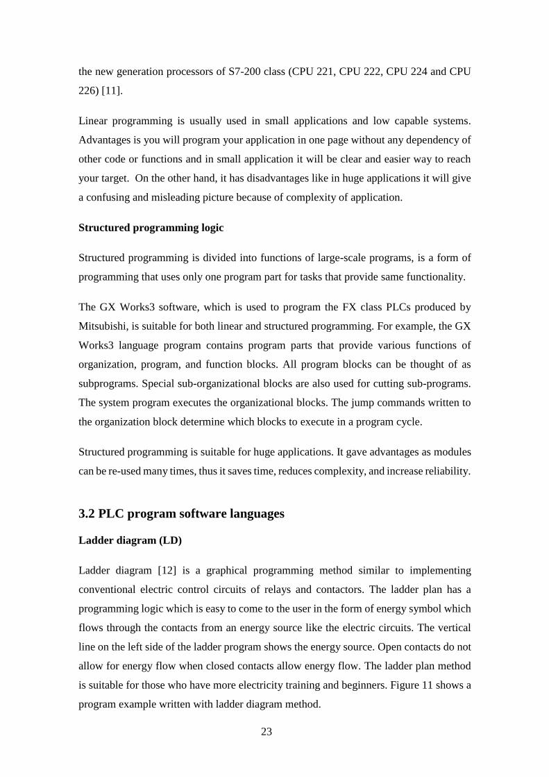

28
4 Implementation and testing of a PLC controlled production
cell
The following chapter describes implementation and testing of a particular robotized
production testing cell at an electronics factory The system is more complex than
conventional PLC control systems because it contains other active controllers Therefore
the PLC software debug turned out to be a complex task giving a motivation for Model
Checking based software testing for the further similar applications
41 Description of production testing cell
The production test system (cell) consists of three parts Test Station (TS) Robot and
Controller Controller is a Mitsubishi FX type PLC that handles synchronization of other
controllers collects sensor readings executes all actuators except robot arm ones During
the normal operation the system has to be able to swap electronic boards in one hour each
full operation cycle should take more than 40 seconds Therefore we can say that PLC
operates as a system Controller
Significance of this robot arm is that there are electronic boards that should be tested
immediately after their composition During this test Robot arm must be communicating
with test station in real time This communication is important because it can cause wrong
results and synchronization of the test station and robot is crucial activity Figure 14
shows Universal Robot UR10 which is controlled by PLC
29
Figure 15 shows data connections between modules implemented as Modbus TCPIP
connections and connection of sensors and actuators
Figure 14 Universal Robots UR10 [18]
Figure 15 System relationship
30
Test Station is an already existing device used in the production Employees were loading
electronic assembly boards to the TS manually TS has 3 slots to test several PCB boards
simultaneously Figure 16 shows a simplified drawing of the TS
Test Station has palettes inside of slots and they are moving horizontally forward and
backward to place boards under test Slots have handles on them to lock electronic boards
on palettes properly to protect any kind of damage For one cycle of test worker should
open empty slot and then open handles to unlock place of board under test Then he can
place board to free palette and lock it by handles Finally he can close slot and start to
test
Selected Robot (see chapter 22) should be a replacement of a human in this process and
work faster and more reliably Particular Robot cannot handle all tasks of the production
testing cell
New parts as a motor to control slots motors to move handles encoders to measure exact
position of motors and end switches were added to the TS Control of the new peripheral
device is a task of Controller (PLC)
Figure 16 Test station
31
42 PLC Controller functions
PLC is main Controller handling all tasks beside Robotrsquos tasks of PCB movements
Modbus protocol over Ethernet communication is chosen to communicate between PLC-
Robot and PLC-Test Station PLC will fetch status of slots from Test Station and related
to statuses PLC will decide what to do the process It will give command to Robot to start
movements vacuum and eject processes Also the PLC has to control motors and read
sensors in system
Since the Test Station works under Windows platform a special windows service was
written to communicate with PLC using the Modbus protocol This service is also sharing
information of slot statuses and condition of test station with PLC controller
43 PLC software implementation
Controller is Mitsubishi FX5U and programming environment is ldquoGX Works3rdquo Figure
17 shows a sample screen from implementation of the program
Figure 17 GX Works3 sample screen
32
PLC needs to be configured for activating High speed counters and PWM signals Slot
motors have encoders and they will be connected to PLCs High speed counter module
On the other hand motor speed will be controlled by PWM signals from PLC This
signals will be processed by motor controllers to regulate the speed of motor
Figure 18 shows High speed counter settings for PLC 3 channels are activated to read 3
encoders Pulse input mode set to ldquo2 Phase 4 Multiplerdquo and it means it uses 2 input pins
for one channel and supports reverse direction Without additional setting PLC will keep
position value of encoder in one integer register for every channel
Another thing to be configured for encoders is input response time The A and B channels
of encoder are connected to separate inputs of PLC and their response time should be
configured In our case movements of motors are approximately 400 rpm Encoder values
are very sensitive and reading cycle of inputs should be very fast Response time for
inputs for encoders are set to minimum time which is 10 micro seconds to get the most
precise value that PLC can read Figure 19 shows response time settings for inputs
Figure 18 High speed counter settings
33
Next step is configuring PWM settings for output Output pins should be defined in
settings to activate and use them in program PWM cycle setting should be configured
also in settings page First 8 outputs support PWM outputs and 3 of them are needed to
use for 3 motors Cycle of PWM signals set to 100ms and motor controllers support this
cycle value Direction of motors are driven by another output pins Figure 20 shows PWM
setting page for output pins
Figure 19 Response time settings
Figure 20 PWM setting page
34
Flow diagram should be created firstly and it will be the basis of further implementation
According to the flow diagram skeleton of application will be created Specific functions
for Mitsubishi FX5U will be added step by step
System has 2 main loops - loading and unloading Ideal system will be focusing on
making all slots empty Unloading process has higher priority to reach his aim Even if
there is empty slot and ready product on picking place system is going to unload firstly
if there is a finished test in test station
To reach this target flow diagram is created to see big picture Figure 21 shows flow
diagram in general It contains single and multi-states Multi states will be explained later
It contains initialize state initializing blocks and then loop of load and unload processes
This diagram will be used also in section 52 for creating abstract Uppaal model of the
control program
35
Figure 21 General flow diagram
36
When PLC controller gets start input from HMI screen firstly its connections are getting
ready and registers from old sessions are clearing Connections have specific functions
To set the connection a protocol should be defined It is decided to use Modbus TCPIP
for communication between all modules and it should be configured in PLC side as a
predefined protocol
Figure 22 shows commands to open and close Ethernet connections To open a connection
ldquoSPSOCOPENrdquo function should be used It has 4 parameters U s1 s2 d This
instruction opens a connection specified in (s1) The set values used for the open
processing is selected in (s2) +0 The result of the ldquoSPSOCOPENrdquo instruction can be
checked with the completion device (d)+0 and (d)+1 To close a connection
ldquoSPSOCOPENrdquo function should be used It has same parameters as ldquoSPSOCOPENrdquo
This instruction closes a connection specified in (s1) (Disconnection of a connection)
The result of the ldquoSPSOCCLOSErdquo instruction can be checked with the completion
device (d) +0 and (d) +1
SD106800 is Boolean register that keeps status of first connection If it is true then
connection is alive SD106801 keeps status of second connection ldquostart_inputrdquo and
ldquostop_inputrdquo are directly connected to HMI screen buttons to get command from operator
to start or stop
To fetch holding registers over Modbus protocol protocol should be defined Figure 23
shows predefined protocol settings
Figure 22 Ethernet settings in ladder diagram
37
4 different Modbus protocols are defined in Figure 23 First protocol reads general outputs
from robot Second protocol sends command to robot These 2 protocols define 2-way
communication between PLC and robot Third protocol reads registers of status of slots
and errors from Test Station Fourth protocol reads special registers from Robot to detect
possible issues Figure 24 shows request packet setting of reading holding registers for
robot communication
Figure 23 Predefined protocol settings
Figure 24 Request packet setting
38
To request packet with Modbus TCPIP protocol inside of package ldquoTransaction IDrdquo
ldquoProtocol IDrdquo ldquoLengthrdquo ldquoModule IDrdquo ldquoFunction coderdquo ldquoHead holding register
numberrdquo and ldquoRead pointsrdquo should be define in correct order It is standard for Modbus
TCPIP protocol
Figure 25 shows response packet setting of reading holding registers for robot
communication To get response packet with Modbus TCPIP protocol inside of package
ldquoTransaction IDrdquo ldquoProtocol IDrdquo ldquoLengthrdquo ldquoModule IDrdquo ldquoFunction coderdquo ldquoNumber
of read bytesrdquo and ldquoDevice datardquo should be define in correct order This processes have
done for all predefined protocols
After all there is another problem PLC and robot can communicate over Modbus with
registers which are already defined in packet settings But problem is PLC and robot
doesnrsquot know anything about each other and they should have another protocol to
understand each other At that point upper level protocol comes in Figure 26 shows the
protocol diagram between PLC and Robot
Figure 25 Response packet setting
39
Figure 26 Protocol diagram between PLC and Robot
40
ldquo1YYZZrdquo is the format of command which PLC sends to robot 1 means action YY is the
first destination and ZZ is the last destination
Possible locations for YY
Command Location
01 PPP
31 Slot 1
32 Slot 2
33 Slot 3
Possible locations for ZZ
Command Location
31 Slot 1
32 Slot 2
33 Slot 3
61 Pass conveyor
62 Fail conveyor
63 Reject conveyor
To complete 1 cycle of command firstly PLC sends command in ldquo1YYZZrdquo format to
robot over register 128 When robot receives it immediately sends same command to
PLC over register 129 to prove that robot got the command properly On next state PLC
Table 1 YY variable
Table 2 ZZ variable
41
sends 0 to robot over register 128 When robot receives 0 it starts to execute command
When execution is finished robot sends 0 over register 129 to PLC to inform about the
termination of execution When PLC receives 0 cycle of process is completed This
sequence will be executed during state 1 and state 2 of PLC program
When PLC and robot are connected properly then PLC starts to initialize system It
checks sensors and motors to be sure if everything works fine Open and close sensors
for 3 slots motor movements open and close sensors for 3 slot handles and pneumatic
motor movements for slot handles should be checked during this initialization Also max
encoder value should be set dynamically during initialization
During initialization firstly slot is opening with constant speed slowly until getting the
signal from the end sensor of the slot and then it configures max encoder value Next it
opens slot handles by pneumatic motors until reach end sensor of handles Then it closes
slot handles when reaching the close sensor Finally slot closes when slot reaches the
close sensor of the slot This process repeats for all slots If there is a problem during
initialization then system stops and shows error message on the HMI screen
After initializing system goes in to loop which it begins the real processes State 999 is
the beginning of loop and after every successful cycle the system comes to state 999 In
state 999 system checks if there is something to unload PLC checks every slot status
from Test Station over Modbus communication If there is nothing to unload then system
goes to state 1000 In state 1000 PLC checks picking place sensor if there is something
to load If yes then PLC checks if there are any empty slots in Test station by Modbus
registers If yes it loads the product to empty slot else it goes back to state 999 and checks
if there is something to unload Basically in the idle mode PLC goes between state 999
and state 1000 Figure 27 shows state 999 in program And Figure 28 shows the state
1000 in program
42
Multi states represent details about unloading and loading states Figure 29 shows details
of multi states This diagram will help also to create Uppaal model in section 52 later
Figure 27 State 999 in ladder diagram
Figure 28 State 1000 in ladder diagram
43
State 1001 is executed if there is something to unload from slot 1 and according to result
it goes to deeper state If pass it goes to state 1010 if fail it goes to state 1020 and if reject
it goes to state 1030 In state 1010 it checks if M1500 is high for slot 1 If not it goes to
state 1500 to open the slot When slot movement is done M1500 Boolean register gets
true If M1500 is high then it checks if handles sensors are open If not it sets register
slot1_handle_open and when it reaches to end sensor it resets register
slot1_handle_open Then it goes to next step state 1
Figure 29 Details of multi states
44
State 1 and state 2 are communication states between PLC and robot In state one PLC
will send command 10131 according to protocol agreement and it means load from
picking place to slot 1 In state one PLC will expect to get same command back from
Robot in register 129 When PLC gets command back it will go to state 2 PLC will send
0 as command to Robot and PLC will wait for 0 as feedback from Robot Robot will load
electronic board from picking place to slot 1 and when it is done robot will send 0 to
PLC Then PLC will complete communication process successfully and goes to state
1011 This state is for closing slot PLC will check if slot1_handle_sensor is high If not
it will activate pneumatic motor to close handles When it reaches to sensor it will check
if M1501 is high If not it will go to state 1501 to close slot When close movement is
done it will go to state 1011 back and M1501 will be high
Once the cycle of unloading slot1 is completed it will go to state 999 to check if there is
unloading This process is same for every slots
44 Reliability experiments with the implemented system
Implementation is done and system correctness has to be validated by testing There are
several methods to test such systems but one of the important point is why and what
should be tested
One of the current project aims is to show that the system does not fail when operating
non-stop all day around When choosing the test method that point should be taken into
account Robot arm project team decided to make stress test on all system to prove the
robustness of software and hardware combination
Stress testing is a test method to force limits of newly developed application or newly
bought products to check the robustness of the system This method will show either
software and hardware related bugs reveal after the development increment
This test will include real scenario of using robot arm in production If it will be
successfully passed robot can be use in real production Explanation of test scenario
Firstly system will initialize itself after initialization operator will place a board to
product picking place Robot will take product from picking place and it places the
product to first empty slot In this case it will be first slot Actions should be like this for
cycle of one product in the following order opening slot opening handles picking board
45
from picking place eject board on slot closing handles closing slot test is starting test
finished open slot open handles picking board from slot eject board to correct conveyor
according to test result This cycle is expected cycle for a product but it has huge
dependencies on the working environment conditions hardware or software bugs
Summary of the first test run In this scenario target is testing 25 electronic board in a row
Automation test summary
RUN Slot Number
1 (ID) 2 (ID) 3 (ID)
1 10 PASS 9 PASS 7 Handle Error Drop Unit PASS
2 8 PASS 5 PASS
3 6 PASS
4 4 Test Fail Stucked in Conveyer
5 3
Dont fit on guiding Pins Push down manually Fail
2 PASS
6 4 Fail
7 10
Test Fail Stucked in Conveyer
1) Restart System 2) removed pins on all pallets from PTC side 3) replaced Samtec DIB saver PTC ($$$) 4) Conveyer Adjustments 5) 3rd slot drop issue fixing hellip 2 hours later
Table 3 First test run
46
8 2
Stucked inReady for Test Statushellip test PASS Fail on Conveyer (missing Target) Fixed by Said
1 PASS 5
Stucked in Ready for Test Statushellip Broken PTC in DUT ($$$)
9 4 PASS 3
Stucked inReady for Test Statushellip Broken PTC in DUT ($$$)
7 PASS
10 6 PASS
11 8 PASS 9 PASS
12 10 PASS
13 1 PASS 4 Stucked in Ready for Test Statushellip
14 2 PASS
15 7 Stucked in Ready for Test Statushellip
Andrey Called
16
The tests have been done for 25 electronic boards and summary is very bad Before testing
each unit had its own unit tests and there were not any major problems After stress tests
it is obvious that the system is not ready to go production During 8th run of slot 3 and 9th
run of slot 2 PTC connectors of boards got broken and it costs a lot Most of the errors
are related to mechanical parts and the test report summary should be analyzed carefully
to find which of the failures is related to PLC program and the algorithm
First run of slot 3 had a problem with slot handles and PLC program does not have error
handling mechanism for this problem and program crashed Root cause of the problem is
slot handle sensors for slot 3 Position of sensors are changed little bit and sensors cannot
detect correct position of handle motors It caused an endless movement command for
handle motors PLC expect to get sensor feedback when handles open until end the point
This bug should be solved
47
8th and 15th runs of slot 1 9th and 13th runs of slot 2 lastly 8th run of slot 3 have same
error ldquoStocked in ready for Test Statusrdquo It means test stations slot received electronic
board successfully and waiting slot to be closed to start testing Root cause of the problem
is a bug in the Test station but PLC program does not have error handling mechanism for
this problem as well and the program crashed PLC should raise an error message on HMI
side to inform operator about this status This feature should be added
Summary of second test run In this scenario target is testing 70 electronic boards in a row
Automation test summary
RUN Slot Number
1 (ID) 2 (ID) 3 (ID)
1 2 PASS 1 PASS 3 PASS
2 8 PASS
3 3 PASS 11 PASS
4 6 PASS 4 PASS
5 20 PASS 21 PASS
6 22 PASS 5 PASS
7 25 PASS 23 PASS 24 PASS
8 10 PASS
9 26 PASS 27 Stucked on Conveyer 48 PASS
10 28 PASS 40 PASS 29 Stucked on Conveyer
11 41 PASS Rejected (not registered)
42 PASS
12 44 PASS 43 PASS 45 PASS
13 47 PASS 46 PASS 12 PASS
14 13 PASS
15 14 Stucked on Conveyer
16 Stucked on Conveyer 17 PASS
16 Increasing the slope for Conveyer
17 47 PASS 18 Test plan didnt load
19 PASS
18 Call Andrey
19 19 PASS 47 Stucked on Conveyer 18
Rejected (not registered) Stucked on Conveyer
Table 4 Second test run
48
20 12 PASS 32 Stucked on Conveyer 31 PASS
21 33 PASS 35 PASS 34 PASS
22 15 PASS 37 PASS 36 PASS
23 38 PASS 39 PASS
24 33 PASS 32 Stucked on Conveyer
25 16 FAIL BS_PWR
26 50
Rejected (not registered) Stucked on Conveyer
33 Stucked on Conveyer 34 PASS
27 36 PASS 16 PASS 31 PASS
28
29
Second test is done after all known bugs are fixed Fixing the bugs took ca 1 week The
system was not operational during this time showing the importance of high quality
software validation Test summary shows there is a significant change between the first
test and the second test but still a lot known bugs were detected
16
64
9
11
F I R S T T E S T S E C O N D T E S T
TEST SUMMARY COMPARISON
Successful run Error
Figure 30 Test summary comparison
49
Second summary seems much better but all system is still not ready to work in production
full time Errors should be analyzed as in first test summary to get a clear picture Most
of the errors are ldquoStucked on conveyorrdquo and it is because of mechanical design problem
of conveyors Over 75 electronic board tests there was only one software error resulting
exception ldquoTest plan didnrsquot loadrdquo Root cause of the problem is because the Test Station
and PLC do not handle any error about this unexpected situation A solution is that PLC
should get loading status of test plan from Test Station and place it to reject conveyor by
directing Robot
After last tests still result is not good enough to use system in production Our target is
error free system and we cannot be sure about it by present test results Manual test
doesnrsquot give precise result there can be still bugs that we cannot predict According to
manual tests all bugs in system are fixed but there are some reports from production
operators that there are still unexpected behaviors Figure 31 shows number of reports
from operators for 1 week At this point there is a need to verify program and whole
system to find any kind of errors and bugs Proposed solution is model based testing to
create model of the system and test any kind of input output sequences to catch the errors
0
1
2
3
Day 1 Day 2 Day 3 Day 4 Day 5 Day 6 Day 7
Number of error reports
Error report
Figure 31 Number of error reports from production
50
5 Model Based Testing of Robot Arm Controller
51 Introduction to model based testing
Model-based testing automates the design of the test cases and the generation of the
traceability matrix More accurately instead of writing hundreds of test cases manually
an abstract model of the system under test is written by test designer and then the model-
based testing tool generates cases from that model The overall time of test design is
reduced besides variety of test suites from the same model can be generated simply by
using different test selection criteria The model-based testing process is divided into the
five main steps as shown in Figure 32
Figure 32 Model based testing process[19]
51
1 Modelling the SUT and its environment
2 Generating abstract tests from the model
3 Concretizing the abstract tests to make them executable
4 Executing the tests on the SUT
5 Analyzing results
In any testing process step 4 and 5 are a normal step they are even in manual testing
Step 3 is like the adaptor stage of keyword-based testing where the meaning of each
keyword is distinct The first two steps differentiate model-based testing from other type
of testing
The first step is to write a model of the system that is wanted to be tested It is called an
abstract model This is because it should be simpler and smaller than SUT itself It ought
to focus on only the key aspects that we would like to test and must omit many other
details of the SUT While writing the model it must be also annotated with requirements
to clearly specify the relationship between the requirements and the model
Afterwards it is desirable to use some tools to investigate that model is steady and has
the desired actions Most modeling systems deliver some verification tools some
interactive tools allow us to find out the model behavior and check whether it is what we
expect or not
The second step is to generate abstract tests of the model some test selection criteria must
be chosen in order to say which tests will be generated from the model because there are
an infinite number of test variations
The main output of this step is a set of abstract tests which are sequences of operations
from the model Since the model uses a simplified view of the SUT these abstract tests
lack some of the detail needed by the SUT and are not directly executable
The third step of model based testing is to transform the abstract tests into executable
concrete tests This may be done by a transformation tool which uses various templates
and mappings to translate each abstract test case into an executable test script
Alternatively it may be done by test adapter that wraps arounds the SUT and implements
52
each abstract operation in terms of the lower-level SUT facilities Either way the goal of
this step is to bridge the gap between the abstract tests and the concrete SUT by adding
in the low-level SUT details that were not mentioned in the abstract model
The fourth step is to execute the concrete tests on the system under test With online
model-based testing the tests will be executed as they are produced so the model-based
testing tool will manage the test execution process and record the results With offline
model-based testing we have just generated a set of concrete test scripts in some existing
language so we can continue to use our existing test execution tools and practices
The fifth step is to analyze the results of the test executions and take corrective action
For each test that reports a failure we must determine the fault that caused that failure
Again this is similar to the traditional test analysis process As usual when a test fails
we may find that it is due to a fault in the SUT or we may find that it is due to a fault in
the test case itself Since we are using model-based testing a fault in the test case must
be due to a fault in the adaptor code or in the model So this is another place where we
get feedback about the correctness of the model
To finish this section let us step back and take a more philosophical view of model-based
testing
It is always the case that test design is based on some kind of model of expected behavior
but with manual test design this model is usually just an informal mental model By
making the model explicit in a notation that can be used by model-based testing tools
we are able to generate tests automatically generate an arbitrary number of tests as well
as obtain more systematic coverage of the model These changes can increase both the
quality and quantity of our test suites
52 Constructing the test model
There are multiple different formalisms used for building conformance testing models
Uppaal Timed Automata (UTA) [20] is decided to be used in the light of the fact that the
53
formalism naturally supports state transitions and time and there exists a group of tools
that support model construction and verification
UTA used for the specification of the requirements are defined as a closed network of
extended timed automata that are called processes The processes are combined into a
single system by the parallel composition known from the process algebra CCS An
example of a system of two automata comprised of 3 locations and 2 transitions each is
given in Figure 33
The nodes of the automata are called locations and the directed edges transitions The
state of an automaton consists of its current location and assignments to all variables
including clocks The initial locations of the automata are graphically denoted by an
additional circle inside the location
Synchronous communication between the processes is by hand-shake synchronization
links that are called channels A channel relates a pair of edges labelled with symbols for
input actions denoted by eg chA and chB in Figure 33 and output actions denoted by
chA and chB where chA and chB are the names of the channels
In Figure 33 there is an example of a model that represents a synchronous remote
procedure call The calling process Process_i and the called process Process_j both
include three locations and two synchronized transitions Process_i initially at location
Start_i initiates the call by executing the send action chA that is synchronized with the
receive action chA in Process_j that is initially at location Start_j The location
Operation denotes the situation where Process_j computes the output y Once done the
control is returned to Process_i by the action chB
Figure 33 Example of a system of two Automata
54
The duration of the execution of the result is specified by the interval [lb ub] where the
upper bound ub is given by the invariant cllt=ub and the lower bound lb by the guard
condition clgt=lb of the transition OperationrarrStop_j The assignment cl=0 on the
transition Start_jrarrOperation ensures that the clock cl is reset when the control reaches
the location Operation The global variables x and y model the input and output arguments
of the remote procedure call and the computation itself is modelled by the function f(x)
defined in the declarations section of the Uppaal model
The inputs and outputs of the test system are modelled using channels labelled in a special
way described later Asynchronous communication between processes is modelled using
global variables accessible to all processes
Formally the Uppaal timed automata are defined as follows Let S denote a finite alphabet
of actions a b hellip and C a finite set of real-valued variables p q r denoting clocks A
guard is a conjunctive formula of atomic constraints of the form p ~ n for p ϵ C ~ϵ le ge
= gt lt and n ϵ N+ We use G(C) to denote the set of clock guards A timed automaton
A is a tuple N l0 E I where N is a finite set of locations (graphically denoted by nodes)
l0 ϵ N is the initial location E ϵ N x G(C) x sum x 2C x N is the set of edges (an edge is
denoted by an arc) and I N rarr G(C) assigns invariants to locations (here we restrict to
constraints in the form p le n or p lt n n ϵ N+ Without the loss of generality we assume
that guard conditions are in conjunctive form with conjuncts including besides clock
constraints also constraints on integer variables Similarly to clock conditions the
propositions on integer variables k are of the form k ~ n for n ϵ N ~ϵ le ge = gt lt For
the formal definition of Uppaal TA full semantics we refer the reader to [20]
According to flow diagram of Robot Arm Controller model of system can be created
Figure 21 general flow diagram and Figure 34 multi states diagram shows details of
system to create model
55
Figure 34 Multi-state diagram
56
State changes conditions and actions can be seen in diagrams First thing is creating
declarations of variables which will be used in models Figure 35 shows some part of
declarations
Sensors inputs outputs Modbus registers some registers which uses for feedback
variables and global variables for model are defined in declarations file Then model can
start to be created Figure 36 shows model of the main program
Figure 35 Declarations
57
Figure 36 Model of main program
58
Model has other processes synchronously works with it They are gclock Input_update
Input_update2 Motor1 Motor2 Robot and Test_station ldquogclockrdquo is global clock defined
5ms according to one cycle of PLC and input response sense Figure 37 shows gclock
process with TU which is time unit dependency for global clock
Input_update process is updating input array which is in use in model Source of inputs
is input_buffer array which user gives to Uppaal and it updates input array by global clock
to simulate system real time Figure 38 shows Input_update process
Ch1 is channel variable and global clock updates this channel by Ch1 action It triggers
Input_update process and other processes by Ch1 condition It provides synchronization
between all processes
Input_update2 process is updating Boolean variables which describe slot statuses of Test
station Source of process is ts_rx registers which is provided by user to Uppaal and
originally PLC fetches it over Modbus communication from Test station Figure 39 shows
Input_update2 process
Figure 37 gclock process
Figure 38 Input_update process
59
One of the most important point of the model is parameterized pattern In current flow
diagram there are some repetitive cycles for different slots and in the Uppaal model They
can be reduced to 1 action by using input parameters for processes Input_update2 process
automatically duplicate itself per every slots by parameter concrete values It gets id_t
parameter as input and it includes array of [012] This array is representation of slots
and every of them symbolize one of the slots According to input number it reproduces
variables which it uses in condition and actions On the other hand loading and unloading
flows are parameterized also In flow diagram every slot has separate action to unload
and load process In Uppaal model only one action is used for every slot and it checks
id_slot variable to process action for correct slot Lastly general inputs are parts of
parameterized pattern By one input array we read all inputs and process them by iterating
over the elements of array
Figure 39 Input_update2 process
60
53 Verifying the correctness of the test model
Model-checking is a promising method for the verification and validation of software
systems The method is applied to software requirement specification and design
specification and aims to increase the reliability and productivity from early stages of the
software development As the number of the success cases increases the method becomes
one of the basic tools for the use in the development of a wide variety of software [21]
Linear Temporal Logic (LTL) or Computation Tree Logic can be used for model
checking Uppaal verification tool supports CTL commands and we will use CTL for
verification CTL is propositional temporal logic with explicit quantification over
possible futures Figure 40 shows sample of tree of computation
Timed Computation Tree Logic (TCTL) is sufficiently expressive to allow for the
formulation of an important set of real-time system properties Formulae in TCTL are
either state or path formulae TCTL extends CTL with atomic clock the set of clocks in
the timed automaton under consideration
Figure 40 Sample of tree of computation
61
Figure 41 shows some examples how the TCTL formulas are interpreted on a simple
computation tree that represents traces of an hypothetical model M Starting from an
initial location a
Altgtϕ (inevitable) true if local condition ϕ (eg valid in yellow locations) is reachable in
all execution paths
Eltgtϕ (possible) true if local condition ϕ (eg valid in a red location) is reachable in at
least one execution path
A[]ϕ (always) is true if local condition ϕ holds in all locations of all execution paths not
valid for given example assuming the initial location is a
ϕ1048576Ψ (leads-to) is true if all paths involving a location where condition ϕ is valid include
thereafter a location where is valid
The TCTL model-checking algorithm with UPTA is built upon the method of model
checking TA Regarding to algorithm proper queries should be created to execute model
checking First we will check deadlocks in the model System shouldnrsquot have any
deadlocks Following query will provide us result of verification if there is any deadlock
in model
A[] not deadlock
Figure 41 Simple computation tree
62
Model is always in progress during its execution and even if there is not any deadlock
varication wouldnrsquot finish until manually stop it Because verification tool will check
deadlocks over infinite time horizon of the model it will stop only when this horizon is
set or verification is manually stopped Figure 42 shows verification settings screen
during deadlock verification
Another method is using time bounded deadlock check The query is shown below
Eltgt gclk lt Const imply deadlock
Additional clock gclk used to check time of verification and Const is time bound of the
verification This query checks if there is any deadlock during defined time bound and
Const defined as 500 cycle Figure 43 shows time bounded deadlock verification result
This query proves that there isnrsquot any deadlock in model and then other properties of the
model can be checked
Figure 42 Deadlock verification
Figure 43 Time bounded deadlock verification
63
Next queries will check specific states and conditions to verify model if itrsquos reaching both
conditions in some cases Following query will provide us result of verification if model
can go state 20 and TS slot 1 status should be ldquoreadyrdquo
Eltgt programs20 ampamp slot_ready[1]
State 20 has task to close slots and slot handles after loading board process And if slot 1
is ready on same time it means system is closing slot 1 after loading process Figure 44
shows verification result of query
Figure 44 Verification of first query
64
As seen in Figure 44 the query property is satisfied successfully and model can reach
this conditions simultaneously Next query will check if system can reach state 2 and
receive command 10132 from Robot
Eltgt programs2 ampamp robot_rx==10132
State 2 communicates with Robot and Robot should send back same command what PLC
sends to it so verification tool will check after PLC sends 10132 command if robot will
send it back Figure 45 shows verification result of query
As seen in Figure 45 the query property is satisfied successfully by model execution
Next query will check if system reaches state 2002 and slot handles activates for slot 3
Eltgt programs2002 ampamp slot_handle_close[2]==1
State 2002 is part of the initialization and responsible for closing slot and handles In
this state verification tool will check if slot handles for slot 3 closes correctly during
initialization Figure 46 shows verification result of query
Figure 45 Verification of second query
65
Firstly ldquoEltgt programs2002 ampamp slot_handle_close[2]==1rdquo query executed accidently
and it raised verification error Problem is 3rd slot is ldquoslot_handle_close[2]rdquo and
ldquoslot_handle_close[3]rdquo is out of range Array expects range of [012] Then with
correct query property satisfied successfully
Other properties can be verified as well when the model is refined during program
updates But for current model the most critical conditions are verified with Uppaal
verification tool as demonstrated above
54 Generating tests from the verified test model
Model-based testing is testing on a model that describes how the system is required to
behave The model built in a suitable machine interpretable formalism can be used to
automatically generate the test cases either offline or online and can also be used as an
oracle that checks if the SUT passes the tests Offline test generation means that tests are
generated before test execution and executed when needed In the case of online test
generation the model is executed in lock step with the IUT The communication between
the Tester and the SUT involves controllable inputs of the SUT and observable outputs
of the SUT For example we can command the robot to move its manipulator to specified
position and we can observe if and when the robot achieves the goal
There are multiple different formalisms used for building models of the requirements
Our choice is Uppaal timed automata (TA) [20] because the formalism naturally supports
state transitions and time and there exists the Uppaal Tron [22] tool that supports online
model-based testing The overall test setup used in the context of model-based testing
with Uppaal Tron as the test engine and dTron as the adapter generation framework is
given in Figure 47 The model contains the specifications of the SUT and the
environment The adapter is responsible for translating abstract model inputs and outputs
to program inputs and outputs The dTron layer allows the adapter to be distributed across
Figure 46 Verification of third query
66
multiple computers while ensuring that time progress in distributed tester models still
stays valid
The test configuration used in this work consists of test execution environment dTron and
one or many test adapters that transform abstract inputoutput symbols of the model to
inputoutput data of the robot The setup is outlined in Fig 1 Uppaal Tron is used as a
primary test execution engine Uppaal Tron simulates interactions between the SUT and
its environment by having two model components ndash the environment and the
implementation model The interactions between these component models are monitored
during model execution When the environment model initiates an input action i Tron
triggers input data generation in the adapter and the actual test data is written to the robot
interface In response to that the robot software produces output data that is transformed
back to model output o Thereafter the equivalence between the output returned and the
output o specified in the model is checked The run continues if there is no conformance
violation ie exists an enabled transition in the model with parameters equivalent to those
passed by the robot In addition to inputoutput conformance Uppaal Tron also checks
for timing conformance We refer the reader to [20] for the details on that relation
Generation of test runs
a) In offline test generation Uppaal model checker generates symbolic test sequences
that witness satisfaction of some property to be covered by given test case These
sequences (they include test inputs and expected outputs) are executed by test
execution environment egUppaal Tron or DTRON
Figure 47 Test setup with Uppaal Tron [22]
67
b) Alternatively for online Conformance testing random walk strategy can be used
on SUT model where the test stimuli are selected on-the-fly and the reactions
from SUT are compared with those predicted by SUT model According to the
Figure 47 an adapter is needed to convert symbolic test inputs and outputs to the
executable ones Online conformance testing suites for duration tests and is
feasible for regression testing
The test adapters for given case study can be created with proper input - output
connections between PLC and PC which runs Uppaal Tron The test passes if during
the test run the conformance relation between the test model and real behavior is not
violated Otherwise test fail is reported and the diagnostic trace exposed by Tron for
error analysis
68
6 Summary
The thesis was focusing on development model checking based PLC software testing
solution The motivation was derived from the actual needs of quicker debug of complex
PLC controlled systems
Certain industrial robot applications were described including original factory automation
solution developed by the author of thesis This particular robot system contains of Test
Station Universal Robots UR10 Mitsubishi FX5U PLC controller sensors and motors
Implementation of PLC software is described and it gives specific proprieties and
commands for Mitsubishi FX5U type PLC Test station Robot and PLC had stress test in
whole system and results showed there is a need for new solution to debug and test PLC
software
Model checking with Uppaal tool was performed Accent of work is combining formal
methods allowing to prove correctness of design against both functional and
dependability requirements The given approach is illustrated in Uppaal model It
contains PLC software and simulation processes of Test station and Robot The
correctness of the control system is successfully verified using Uppaal verification tool
Further work should focus on connecting Uppaal verification tool to real hardware For
that approach Uppaal Tron extension is needed for allowing Uppaal model to use with
other environments Additionally physical adapter is needed to connect input outputs of
the PLC controller to PC This adapter can be build according to PLC specifications With
Uppaal Tron verification can be done by comparison between Uppaal model and real-
time PLC input outputs
69
References
[1] J Bloem ldquoThe Fourth Industrial Revolution Things to Tighten the Link Between
it and otrdquo VINT Res Rep pp 1ndash39 2014
[2] M Newman ldquoSoftware errors cost US economy $595 billion annuallyrdquo NIST
Assesses Tech Needs Ind to Improv 2002
[3] ldquoAdvantech factory automationrdquo [Online] Available
httpwwwrrfloodycomAdvantechFAhtml [Accessed 15-Mar-2017]
[4] ldquoLadder Logic Examples and PLC Programming Examplesrdquo [Online] Available
httpwwwplcacademycomladder-logic-examples [Accessed 15-Mar-2017]
[5] D Darvas B Fernaacutendez Adiego A Voumlroumls T Bartha E Blanco Vintildeuela and V
M Gonzaacutelez Suaacuterez ldquoFormal Verification of Complex Properties on PLC
Programsrdquo Springer Berlin Heidelberg 2014 pp 284ndash299
[6] ldquoIndustrial robots What are the different typesrdquo [Online] Available
httpblogrobotiqcombid63528what-are-the-different-types-of-industrial-
robots [Accessed 19-Mar-2017]
[7] ldquoMaterial Handling Robotrdquo [Online] Available
httpswwwrobotscomapplicationsmaterial-handling [Accessed 19-Mar-
2017]
[8] K Hee ldquoObject-Oriented Modeling Simulation and Automatic Generation of
PLC Ladder Logicrdquo in Programmable Logic Controller InTech 2010
[9] ldquoUniversal Robotics UR10rdquo [Online] Available
httpfabcbamiteducontenttoolsuniversal_robot_armsindexhtml [Accessed
23-Apr-2017]
[10] ldquoFX5U-64MT-ESS | Mitsubishi FX5U FX5U-64MT-ESSrdquo [Online] Available
httpwww999mitsubishicommitsubishi-fx5u-fx5u-64mt-ess [Accessed 15-
Mar-2017]
[11] ldquoELEKTRIK-ELEKTRONIK TEKNOLOJISI PLC PROGRAMLAMA
TEKNIKLERI 523EO0053rdquo 2011
[12] S S Peng and M C Zhou ldquoLadder Diagram and Petri-Net-Based Discrete-
Event Control Design Methodsrdquo IEEE Trans Syst Man Cybern Part C
(Applications Rev vol 34 no 4 pp 523ndash531 Nov 2004
[13] K-H John and M Tiegelkamp IEC 61131-3 Programming industrial
automation systems concepts and programming languages requirements for
programming systems decision-making aids Springer 2010
[14] B Rexroth Corporation ldquoUnderstanding the IEC61131-3 Programming
Languagesrdquo
[15] Z Aspar M Khalil-Hani and N Shaikh-Husin ldquoDeadlock detection and
avoidance using Signal Interpreted Petri Netsrdquo in 2012 IEEE International
Conference on Circuits and Systems (ICCAS) 2012 pp 150ndash155
[16] J Martins C Lima H Martiacutenez and A Grau ldquoA MatlabSimulink framework
for PLC controlled processesrdquo
[17] B F Adiego D Darvas J C Tournier E B Vintildeuela and V M Gonzaacutelez
Suaacuterez ldquoBringing automated model checking to plc program development - A
70
CERN case studyrdquo in Advances in the Astronautical Sciences 2014 vol 12 pp
394ndash399
[18] ldquoAksIMTM supports Universal Robots for smart factory automationrdquo [Online]
Available httpwwwrenishawcomenaksim-supports-universal-robots-for-
smart-factory-automation-factory-automation--40903 [Accessed 15-Mar-2017]
[19] M Utting and B Legeard Practical model-based testing a tools approach
Morgan Kaufmann Publishers 2006
[20] J Bengtsson and W Yi ldquoTimed Automata Semantics Algorithms and Toolsrdquo
Springer Berlin Heidelberg 2004 pp 87ndash124
[21] S Nakajima ldquoModel-Checking Verification for Reliable Web Servicerdquo
[22] K G Larsen M Mikucionis B Nielsen and A Skou ldquoTesting Real-Time
Embedded Software using UPPAAL-TRON An Industrial Case Studyrdquo

29
Figure 15 shows data connections between modules implemented as Modbus TCPIP
connections and connection of sensors and actuators
Figure 14 Universal Robots UR10 [18]
Figure 15 System relationship
30
Test Station is an already existing device used in the production Employees were loading
electronic assembly boards to the TS manually TS has 3 slots to test several PCB boards
simultaneously Figure 16 shows a simplified drawing of the TS
Test Station has palettes inside of slots and they are moving horizontally forward and
backward to place boards under test Slots have handles on them to lock electronic boards
on palettes properly to protect any kind of damage For one cycle of test worker should
open empty slot and then open handles to unlock place of board under test Then he can
place board to free palette and lock it by handles Finally he can close slot and start to
test
Selected Robot (see chapter 22) should be a replacement of a human in this process and
work faster and more reliably Particular Robot cannot handle all tasks of the production
testing cell
New parts as a motor to control slots motors to move handles encoders to measure exact
position of motors and end switches were added to the TS Control of the new peripheral
device is a task of Controller (PLC)
Figure 16 Test station
31
42 PLC Controller functions
PLC is main Controller handling all tasks beside Robotrsquos tasks of PCB movements
Modbus protocol over Ethernet communication is chosen to communicate between PLC-
Robot and PLC-Test Station PLC will fetch status of slots from Test Station and related
to statuses PLC will decide what to do the process It will give command to Robot to start
movements vacuum and eject processes Also the PLC has to control motors and read
sensors in system
Since the Test Station works under Windows platform a special windows service was
written to communicate with PLC using the Modbus protocol This service is also sharing
information of slot statuses and condition of test station with PLC controller
43 PLC software implementation
Controller is Mitsubishi FX5U and programming environment is ldquoGX Works3rdquo Figure
17 shows a sample screen from implementation of the program
Figure 17 GX Works3 sample screen
32
PLC needs to be configured for activating High speed counters and PWM signals Slot
motors have encoders and they will be connected to PLCs High speed counter module
On the other hand motor speed will be controlled by PWM signals from PLC This
signals will be processed by motor controllers to regulate the speed of motor
Figure 18 shows High speed counter settings for PLC 3 channels are activated to read 3
encoders Pulse input mode set to ldquo2 Phase 4 Multiplerdquo and it means it uses 2 input pins
for one channel and supports reverse direction Without additional setting PLC will keep
position value of encoder in one integer register for every channel
Another thing to be configured for encoders is input response time The A and B channels
of encoder are connected to separate inputs of PLC and their response time should be
configured In our case movements of motors are approximately 400 rpm Encoder values
are very sensitive and reading cycle of inputs should be very fast Response time for
inputs for encoders are set to minimum time which is 10 micro seconds to get the most
precise value that PLC can read Figure 19 shows response time settings for inputs
Figure 18 High speed counter settings
33
Next step is configuring PWM settings for output Output pins should be defined in
settings to activate and use them in program PWM cycle setting should be configured
also in settings page First 8 outputs support PWM outputs and 3 of them are needed to
use for 3 motors Cycle of PWM signals set to 100ms and motor controllers support this
cycle value Direction of motors are driven by another output pins Figure 20 shows PWM
setting page for output pins
Figure 19 Response time settings
Figure 20 PWM setting page
34
Flow diagram should be created firstly and it will be the basis of further implementation
According to the flow diagram skeleton of application will be created Specific functions
for Mitsubishi FX5U will be added step by step
System has 2 main loops - loading and unloading Ideal system will be focusing on
making all slots empty Unloading process has higher priority to reach his aim Even if
there is empty slot and ready product on picking place system is going to unload firstly
if there is a finished test in test station
To reach this target flow diagram is created to see big picture Figure 21 shows flow
diagram in general It contains single and multi-states Multi states will be explained later
It contains initialize state initializing blocks and then loop of load and unload processes
This diagram will be used also in section 52 for creating abstract Uppaal model of the
control program
35
Figure 21 General flow diagram
36
When PLC controller gets start input from HMI screen firstly its connections are getting
ready and registers from old sessions are clearing Connections have specific functions
To set the connection a protocol should be defined It is decided to use Modbus TCPIP
for communication between all modules and it should be configured in PLC side as a
predefined protocol
Figure 22 shows commands to open and close Ethernet connections To open a connection
ldquoSPSOCOPENrdquo function should be used It has 4 parameters U s1 s2 d This
instruction opens a connection specified in (s1) The set values used for the open
processing is selected in (s2) +0 The result of the ldquoSPSOCOPENrdquo instruction can be
checked with the completion device (d)+0 and (d)+1 To close a connection
ldquoSPSOCOPENrdquo function should be used It has same parameters as ldquoSPSOCOPENrdquo
This instruction closes a connection specified in (s1) (Disconnection of a connection)
The result of the ldquoSPSOCCLOSErdquo instruction can be checked with the completion
device (d) +0 and (d) +1
SD106800 is Boolean register that keeps status of first connection If it is true then
connection is alive SD106801 keeps status of second connection ldquostart_inputrdquo and
ldquostop_inputrdquo are directly connected to HMI screen buttons to get command from operator
to start or stop
To fetch holding registers over Modbus protocol protocol should be defined Figure 23
shows predefined protocol settings
Figure 22 Ethernet settings in ladder diagram
37
4 different Modbus protocols are defined in Figure 23 First protocol reads general outputs
from robot Second protocol sends command to robot These 2 protocols define 2-way
communication between PLC and robot Third protocol reads registers of status of slots
and errors from Test Station Fourth protocol reads special registers from Robot to detect
possible issues Figure 24 shows request packet setting of reading holding registers for
robot communication
Figure 23 Predefined protocol settings
Figure 24 Request packet setting
38
To request packet with Modbus TCPIP protocol inside of package ldquoTransaction IDrdquo
ldquoProtocol IDrdquo ldquoLengthrdquo ldquoModule IDrdquo ldquoFunction coderdquo ldquoHead holding register
numberrdquo and ldquoRead pointsrdquo should be define in correct order It is standard for Modbus
TCPIP protocol
Figure 25 shows response packet setting of reading holding registers for robot
communication To get response packet with Modbus TCPIP protocol inside of package
ldquoTransaction IDrdquo ldquoProtocol IDrdquo ldquoLengthrdquo ldquoModule IDrdquo ldquoFunction coderdquo ldquoNumber
of read bytesrdquo and ldquoDevice datardquo should be define in correct order This processes have
done for all predefined protocols
After all there is another problem PLC and robot can communicate over Modbus with
registers which are already defined in packet settings But problem is PLC and robot
doesnrsquot know anything about each other and they should have another protocol to
understand each other At that point upper level protocol comes in Figure 26 shows the
protocol diagram between PLC and Robot
Figure 25 Response packet setting
39
Figure 26 Protocol diagram between PLC and Robot
40
ldquo1YYZZrdquo is the format of command which PLC sends to robot 1 means action YY is the
first destination and ZZ is the last destination
Possible locations for YY
Command Location
01 PPP
31 Slot 1
32 Slot 2
33 Slot 3
Possible locations for ZZ
Command Location
31 Slot 1
32 Slot 2
33 Slot 3
61 Pass conveyor
62 Fail conveyor
63 Reject conveyor
To complete 1 cycle of command firstly PLC sends command in ldquo1YYZZrdquo format to
robot over register 128 When robot receives it immediately sends same command to
PLC over register 129 to prove that robot got the command properly On next state PLC
Table 1 YY variable
Table 2 ZZ variable
41
sends 0 to robot over register 128 When robot receives 0 it starts to execute command
When execution is finished robot sends 0 over register 129 to PLC to inform about the
termination of execution When PLC receives 0 cycle of process is completed This
sequence will be executed during state 1 and state 2 of PLC program
When PLC and robot are connected properly then PLC starts to initialize system It
checks sensors and motors to be sure if everything works fine Open and close sensors
for 3 slots motor movements open and close sensors for 3 slot handles and pneumatic
motor movements for slot handles should be checked during this initialization Also max
encoder value should be set dynamically during initialization
During initialization firstly slot is opening with constant speed slowly until getting the
signal from the end sensor of the slot and then it configures max encoder value Next it
opens slot handles by pneumatic motors until reach end sensor of handles Then it closes
slot handles when reaching the close sensor Finally slot closes when slot reaches the
close sensor of the slot This process repeats for all slots If there is a problem during
initialization then system stops and shows error message on the HMI screen
After initializing system goes in to loop which it begins the real processes State 999 is
the beginning of loop and after every successful cycle the system comes to state 999 In
state 999 system checks if there is something to unload PLC checks every slot status
from Test Station over Modbus communication If there is nothing to unload then system
goes to state 1000 In state 1000 PLC checks picking place sensor if there is something
to load If yes then PLC checks if there are any empty slots in Test station by Modbus
registers If yes it loads the product to empty slot else it goes back to state 999 and checks
if there is something to unload Basically in the idle mode PLC goes between state 999
and state 1000 Figure 27 shows state 999 in program And Figure 28 shows the state
1000 in program
42
Multi states represent details about unloading and loading states Figure 29 shows details
of multi states This diagram will help also to create Uppaal model in section 52 later
Figure 27 State 999 in ladder diagram
Figure 28 State 1000 in ladder diagram
43
State 1001 is executed if there is something to unload from slot 1 and according to result
it goes to deeper state If pass it goes to state 1010 if fail it goes to state 1020 and if reject
it goes to state 1030 In state 1010 it checks if M1500 is high for slot 1 If not it goes to
state 1500 to open the slot When slot movement is done M1500 Boolean register gets
true If M1500 is high then it checks if handles sensors are open If not it sets register
slot1_handle_open and when it reaches to end sensor it resets register
slot1_handle_open Then it goes to next step state 1
Figure 29 Details of multi states
44
State 1 and state 2 are communication states between PLC and robot In state one PLC
will send command 10131 according to protocol agreement and it means load from
picking place to slot 1 In state one PLC will expect to get same command back from
Robot in register 129 When PLC gets command back it will go to state 2 PLC will send
0 as command to Robot and PLC will wait for 0 as feedback from Robot Robot will load
electronic board from picking place to slot 1 and when it is done robot will send 0 to
PLC Then PLC will complete communication process successfully and goes to state
1011 This state is for closing slot PLC will check if slot1_handle_sensor is high If not
it will activate pneumatic motor to close handles When it reaches to sensor it will check
if M1501 is high If not it will go to state 1501 to close slot When close movement is
done it will go to state 1011 back and M1501 will be high
Once the cycle of unloading slot1 is completed it will go to state 999 to check if there is
unloading This process is same for every slots
44 Reliability experiments with the implemented system
Implementation is done and system correctness has to be validated by testing There are
several methods to test such systems but one of the important point is why and what
should be tested
One of the current project aims is to show that the system does not fail when operating
non-stop all day around When choosing the test method that point should be taken into
account Robot arm project team decided to make stress test on all system to prove the
robustness of software and hardware combination
Stress testing is a test method to force limits of newly developed application or newly
bought products to check the robustness of the system This method will show either
software and hardware related bugs reveal after the development increment
This test will include real scenario of using robot arm in production If it will be
successfully passed robot can be use in real production Explanation of test scenario
Firstly system will initialize itself after initialization operator will place a board to
product picking place Robot will take product from picking place and it places the
product to first empty slot In this case it will be first slot Actions should be like this for
cycle of one product in the following order opening slot opening handles picking board
45
from picking place eject board on slot closing handles closing slot test is starting test
finished open slot open handles picking board from slot eject board to correct conveyor
according to test result This cycle is expected cycle for a product but it has huge
dependencies on the working environment conditions hardware or software bugs
Summary of the first test run In this scenario target is testing 25 electronic board in a row
Automation test summary
RUN Slot Number
1 (ID) 2 (ID) 3 (ID)
1 10 PASS 9 PASS 7 Handle Error Drop Unit PASS
2 8 PASS 5 PASS
3 6 PASS
4 4 Test Fail Stucked in Conveyer
5 3
Dont fit on guiding Pins Push down manually Fail
2 PASS
6 4 Fail
7 10
Test Fail Stucked in Conveyer
1) Restart System 2) removed pins on all pallets from PTC side 3) replaced Samtec DIB saver PTC ($$$) 4) Conveyer Adjustments 5) 3rd slot drop issue fixing hellip 2 hours later
Table 3 First test run
46
8 2
Stucked inReady for Test Statushellip test PASS Fail on Conveyer (missing Target) Fixed by Said
1 PASS 5
Stucked in Ready for Test Statushellip Broken PTC in DUT ($$$)
9 4 PASS 3
Stucked inReady for Test Statushellip Broken PTC in DUT ($$$)
7 PASS
10 6 PASS
11 8 PASS 9 PASS
12 10 PASS
13 1 PASS 4 Stucked in Ready for Test Statushellip
14 2 PASS
15 7 Stucked in Ready for Test Statushellip
Andrey Called
16
The tests have been done for 25 electronic boards and summary is very bad Before testing
each unit had its own unit tests and there were not any major problems After stress tests
it is obvious that the system is not ready to go production During 8th run of slot 3 and 9th
run of slot 2 PTC connectors of boards got broken and it costs a lot Most of the errors
are related to mechanical parts and the test report summary should be analyzed carefully
to find which of the failures is related to PLC program and the algorithm
First run of slot 3 had a problem with slot handles and PLC program does not have error
handling mechanism for this problem and program crashed Root cause of the problem is
slot handle sensors for slot 3 Position of sensors are changed little bit and sensors cannot
detect correct position of handle motors It caused an endless movement command for
handle motors PLC expect to get sensor feedback when handles open until end the point
This bug should be solved
47
8th and 15th runs of slot 1 9th and 13th runs of slot 2 lastly 8th run of slot 3 have same
error ldquoStocked in ready for Test Statusrdquo It means test stations slot received electronic
board successfully and waiting slot to be closed to start testing Root cause of the problem
is a bug in the Test station but PLC program does not have error handling mechanism for
this problem as well and the program crashed PLC should raise an error message on HMI
side to inform operator about this status This feature should be added
Summary of second test run In this scenario target is testing 70 electronic boards in a row
Automation test summary
RUN Slot Number
1 (ID) 2 (ID) 3 (ID)
1 2 PASS 1 PASS 3 PASS
2 8 PASS
3 3 PASS 11 PASS
4 6 PASS 4 PASS
5 20 PASS 21 PASS
6 22 PASS 5 PASS
7 25 PASS 23 PASS 24 PASS
8 10 PASS
9 26 PASS 27 Stucked on Conveyer 48 PASS
10 28 PASS 40 PASS 29 Stucked on Conveyer
11 41 PASS Rejected (not registered)
42 PASS
12 44 PASS 43 PASS 45 PASS
13 47 PASS 46 PASS 12 PASS
14 13 PASS
15 14 Stucked on Conveyer
16 Stucked on Conveyer 17 PASS
16 Increasing the slope for Conveyer
17 47 PASS 18 Test plan didnt load
19 PASS
18 Call Andrey
19 19 PASS 47 Stucked on Conveyer 18
Rejected (not registered) Stucked on Conveyer
Table 4 Second test run
48
20 12 PASS 32 Stucked on Conveyer 31 PASS
21 33 PASS 35 PASS 34 PASS
22 15 PASS 37 PASS 36 PASS
23 38 PASS 39 PASS
24 33 PASS 32 Stucked on Conveyer
25 16 FAIL BS_PWR
26 50
Rejected (not registered) Stucked on Conveyer
33 Stucked on Conveyer 34 PASS
27 36 PASS 16 PASS 31 PASS
28
29
Second test is done after all known bugs are fixed Fixing the bugs took ca 1 week The
system was not operational during this time showing the importance of high quality
software validation Test summary shows there is a significant change between the first
test and the second test but still a lot known bugs were detected
16
64
9
11
F I R S T T E S T S E C O N D T E S T
TEST SUMMARY COMPARISON
Successful run Error
Figure 30 Test summary comparison
49
Second summary seems much better but all system is still not ready to work in production
full time Errors should be analyzed as in first test summary to get a clear picture Most
of the errors are ldquoStucked on conveyorrdquo and it is because of mechanical design problem
of conveyors Over 75 electronic board tests there was only one software error resulting
exception ldquoTest plan didnrsquot loadrdquo Root cause of the problem is because the Test Station
and PLC do not handle any error about this unexpected situation A solution is that PLC
should get loading status of test plan from Test Station and place it to reject conveyor by
directing Robot
After last tests still result is not good enough to use system in production Our target is
error free system and we cannot be sure about it by present test results Manual test
doesnrsquot give precise result there can be still bugs that we cannot predict According to
manual tests all bugs in system are fixed but there are some reports from production
operators that there are still unexpected behaviors Figure 31 shows number of reports
from operators for 1 week At this point there is a need to verify program and whole
system to find any kind of errors and bugs Proposed solution is model based testing to
create model of the system and test any kind of input output sequences to catch the errors
0
1
2
3
Day 1 Day 2 Day 3 Day 4 Day 5 Day 6 Day 7
Number of error reports
Error report
Figure 31 Number of error reports from production
50
5 Model Based Testing of Robot Arm Controller
51 Introduction to model based testing
Model-based testing automates the design of the test cases and the generation of the
traceability matrix More accurately instead of writing hundreds of test cases manually
an abstract model of the system under test is written by test designer and then the model-
based testing tool generates cases from that model The overall time of test design is
reduced besides variety of test suites from the same model can be generated simply by
using different test selection criteria The model-based testing process is divided into the
five main steps as shown in Figure 32
Figure 32 Model based testing process[19]
51
1 Modelling the SUT and its environment
2 Generating abstract tests from the model
3 Concretizing the abstract tests to make them executable
4 Executing the tests on the SUT
5 Analyzing results
In any testing process step 4 and 5 are a normal step they are even in manual testing
Step 3 is like the adaptor stage of keyword-based testing where the meaning of each
keyword is distinct The first two steps differentiate model-based testing from other type
of testing
The first step is to write a model of the system that is wanted to be tested It is called an
abstract model This is because it should be simpler and smaller than SUT itself It ought
to focus on only the key aspects that we would like to test and must omit many other
details of the SUT While writing the model it must be also annotated with requirements
to clearly specify the relationship between the requirements and the model
Afterwards it is desirable to use some tools to investigate that model is steady and has
the desired actions Most modeling systems deliver some verification tools some
interactive tools allow us to find out the model behavior and check whether it is what we
expect or not
The second step is to generate abstract tests of the model some test selection criteria must
be chosen in order to say which tests will be generated from the model because there are
an infinite number of test variations
The main output of this step is a set of abstract tests which are sequences of operations
from the model Since the model uses a simplified view of the SUT these abstract tests
lack some of the detail needed by the SUT and are not directly executable
The third step of model based testing is to transform the abstract tests into executable
concrete tests This may be done by a transformation tool which uses various templates
and mappings to translate each abstract test case into an executable test script
Alternatively it may be done by test adapter that wraps arounds the SUT and implements
52
each abstract operation in terms of the lower-level SUT facilities Either way the goal of
this step is to bridge the gap between the abstract tests and the concrete SUT by adding
in the low-level SUT details that were not mentioned in the abstract model
The fourth step is to execute the concrete tests on the system under test With online
model-based testing the tests will be executed as they are produced so the model-based
testing tool will manage the test execution process and record the results With offline
model-based testing we have just generated a set of concrete test scripts in some existing
language so we can continue to use our existing test execution tools and practices
The fifth step is to analyze the results of the test executions and take corrective action
For each test that reports a failure we must determine the fault that caused that failure
Again this is similar to the traditional test analysis process As usual when a test fails
we may find that it is due to a fault in the SUT or we may find that it is due to a fault in
the test case itself Since we are using model-based testing a fault in the test case must
be due to a fault in the adaptor code or in the model So this is another place where we
get feedback about the correctness of the model
To finish this section let us step back and take a more philosophical view of model-based
testing
It is always the case that test design is based on some kind of model of expected behavior
but with manual test design this model is usually just an informal mental model By
making the model explicit in a notation that can be used by model-based testing tools
we are able to generate tests automatically generate an arbitrary number of tests as well
as obtain more systematic coverage of the model These changes can increase both the
quality and quantity of our test suites
52 Constructing the test model
There are multiple different formalisms used for building conformance testing models
Uppaal Timed Automata (UTA) [20] is decided to be used in the light of the fact that the
53
formalism naturally supports state transitions and time and there exists a group of tools
that support model construction and verification
UTA used for the specification of the requirements are defined as a closed network of
extended timed automata that are called processes The processes are combined into a
single system by the parallel composition known from the process algebra CCS An
example of a system of two automata comprised of 3 locations and 2 transitions each is
given in Figure 33
The nodes of the automata are called locations and the directed edges transitions The
state of an automaton consists of its current location and assignments to all variables
including clocks The initial locations of the automata are graphically denoted by an
additional circle inside the location
Synchronous communication between the processes is by hand-shake synchronization
links that are called channels A channel relates a pair of edges labelled with symbols for
input actions denoted by eg chA and chB in Figure 33 and output actions denoted by
chA and chB where chA and chB are the names of the channels
In Figure 33 there is an example of a model that represents a synchronous remote
procedure call The calling process Process_i and the called process Process_j both
include three locations and two synchronized transitions Process_i initially at location
Start_i initiates the call by executing the send action chA that is synchronized with the
receive action chA in Process_j that is initially at location Start_j The location
Operation denotes the situation where Process_j computes the output y Once done the
control is returned to Process_i by the action chB
Figure 33 Example of a system of two Automata
54
The duration of the execution of the result is specified by the interval [lb ub] where the
upper bound ub is given by the invariant cllt=ub and the lower bound lb by the guard
condition clgt=lb of the transition OperationrarrStop_j The assignment cl=0 on the
transition Start_jrarrOperation ensures that the clock cl is reset when the control reaches
the location Operation The global variables x and y model the input and output arguments
of the remote procedure call and the computation itself is modelled by the function f(x)
defined in the declarations section of the Uppaal model
The inputs and outputs of the test system are modelled using channels labelled in a special
way described later Asynchronous communication between processes is modelled using
global variables accessible to all processes
Formally the Uppaal timed automata are defined as follows Let S denote a finite alphabet
of actions a b hellip and C a finite set of real-valued variables p q r denoting clocks A
guard is a conjunctive formula of atomic constraints of the form p ~ n for p ϵ C ~ϵ le ge
= gt lt and n ϵ N+ We use G(C) to denote the set of clock guards A timed automaton
A is a tuple N l0 E I where N is a finite set of locations (graphically denoted by nodes)
l0 ϵ N is the initial location E ϵ N x G(C) x sum x 2C x N is the set of edges (an edge is
denoted by an arc) and I N rarr G(C) assigns invariants to locations (here we restrict to
constraints in the form p le n or p lt n n ϵ N+ Without the loss of generality we assume
that guard conditions are in conjunctive form with conjuncts including besides clock
constraints also constraints on integer variables Similarly to clock conditions the
propositions on integer variables k are of the form k ~ n for n ϵ N ~ϵ le ge = gt lt For
the formal definition of Uppaal TA full semantics we refer the reader to [20]
According to flow diagram of Robot Arm Controller model of system can be created
Figure 21 general flow diagram and Figure 34 multi states diagram shows details of
system to create model
55
Figure 34 Multi-state diagram
56
State changes conditions and actions can be seen in diagrams First thing is creating
declarations of variables which will be used in models Figure 35 shows some part of
declarations
Sensors inputs outputs Modbus registers some registers which uses for feedback
variables and global variables for model are defined in declarations file Then model can
start to be created Figure 36 shows model of the main program
Figure 35 Declarations
57
Figure 36 Model of main program
58
Model has other processes synchronously works with it They are gclock Input_update
Input_update2 Motor1 Motor2 Robot and Test_station ldquogclockrdquo is global clock defined
5ms according to one cycle of PLC and input response sense Figure 37 shows gclock
process with TU which is time unit dependency for global clock
Input_update process is updating input array which is in use in model Source of inputs
is input_buffer array which user gives to Uppaal and it updates input array by global clock
to simulate system real time Figure 38 shows Input_update process
Ch1 is channel variable and global clock updates this channel by Ch1 action It triggers
Input_update process and other processes by Ch1 condition It provides synchronization
between all processes
Input_update2 process is updating Boolean variables which describe slot statuses of Test
station Source of process is ts_rx registers which is provided by user to Uppaal and
originally PLC fetches it over Modbus communication from Test station Figure 39 shows
Input_update2 process
Figure 37 gclock process
Figure 38 Input_update process
59
One of the most important point of the model is parameterized pattern In current flow
diagram there are some repetitive cycles for different slots and in the Uppaal model They
can be reduced to 1 action by using input parameters for processes Input_update2 process
automatically duplicate itself per every slots by parameter concrete values It gets id_t
parameter as input and it includes array of [012] This array is representation of slots
and every of them symbolize one of the slots According to input number it reproduces
variables which it uses in condition and actions On the other hand loading and unloading
flows are parameterized also In flow diagram every slot has separate action to unload
and load process In Uppaal model only one action is used for every slot and it checks
id_slot variable to process action for correct slot Lastly general inputs are parts of
parameterized pattern By one input array we read all inputs and process them by iterating
over the elements of array
Figure 39 Input_update2 process
60
53 Verifying the correctness of the test model
Model-checking is a promising method for the verification and validation of software
systems The method is applied to software requirement specification and design
specification and aims to increase the reliability and productivity from early stages of the
software development As the number of the success cases increases the method becomes
one of the basic tools for the use in the development of a wide variety of software [21]
Linear Temporal Logic (LTL) or Computation Tree Logic can be used for model
checking Uppaal verification tool supports CTL commands and we will use CTL for
verification CTL is propositional temporal logic with explicit quantification over
possible futures Figure 40 shows sample of tree of computation
Timed Computation Tree Logic (TCTL) is sufficiently expressive to allow for the
formulation of an important set of real-time system properties Formulae in TCTL are
either state or path formulae TCTL extends CTL with atomic clock the set of clocks in
the timed automaton under consideration
Figure 40 Sample of tree of computation
61
Figure 41 shows some examples how the TCTL formulas are interpreted on a simple
computation tree that represents traces of an hypothetical model M Starting from an
initial location a
Altgtϕ (inevitable) true if local condition ϕ (eg valid in yellow locations) is reachable in
all execution paths
Eltgtϕ (possible) true if local condition ϕ (eg valid in a red location) is reachable in at
least one execution path
A[]ϕ (always) is true if local condition ϕ holds in all locations of all execution paths not
valid for given example assuming the initial location is a
ϕ1048576Ψ (leads-to) is true if all paths involving a location where condition ϕ is valid include
thereafter a location where is valid
The TCTL model-checking algorithm with UPTA is built upon the method of model
checking TA Regarding to algorithm proper queries should be created to execute model
checking First we will check deadlocks in the model System shouldnrsquot have any
deadlocks Following query will provide us result of verification if there is any deadlock
in model
A[] not deadlock
Figure 41 Simple computation tree
62
Model is always in progress during its execution and even if there is not any deadlock
varication wouldnrsquot finish until manually stop it Because verification tool will check
deadlocks over infinite time horizon of the model it will stop only when this horizon is
set or verification is manually stopped Figure 42 shows verification settings screen
during deadlock verification
Another method is using time bounded deadlock check The query is shown below
Eltgt gclk lt Const imply deadlock
Additional clock gclk used to check time of verification and Const is time bound of the
verification This query checks if there is any deadlock during defined time bound and
Const defined as 500 cycle Figure 43 shows time bounded deadlock verification result
This query proves that there isnrsquot any deadlock in model and then other properties of the
model can be checked
Figure 42 Deadlock verification
Figure 43 Time bounded deadlock verification
63
Next queries will check specific states and conditions to verify model if itrsquos reaching both
conditions in some cases Following query will provide us result of verification if model
can go state 20 and TS slot 1 status should be ldquoreadyrdquo
Eltgt programs20 ampamp slot_ready[1]
State 20 has task to close slots and slot handles after loading board process And if slot 1
is ready on same time it means system is closing slot 1 after loading process Figure 44
shows verification result of query
Figure 44 Verification of first query
64
As seen in Figure 44 the query property is satisfied successfully and model can reach
this conditions simultaneously Next query will check if system can reach state 2 and
receive command 10132 from Robot
Eltgt programs2 ampamp robot_rx==10132
State 2 communicates with Robot and Robot should send back same command what PLC
sends to it so verification tool will check after PLC sends 10132 command if robot will
send it back Figure 45 shows verification result of query
As seen in Figure 45 the query property is satisfied successfully by model execution
Next query will check if system reaches state 2002 and slot handles activates for slot 3
Eltgt programs2002 ampamp slot_handle_close[2]==1
State 2002 is part of the initialization and responsible for closing slot and handles In
this state verification tool will check if slot handles for slot 3 closes correctly during
initialization Figure 46 shows verification result of query
Figure 45 Verification of second query
65
Firstly ldquoEltgt programs2002 ampamp slot_handle_close[2]==1rdquo query executed accidently
and it raised verification error Problem is 3rd slot is ldquoslot_handle_close[2]rdquo and
ldquoslot_handle_close[3]rdquo is out of range Array expects range of [012] Then with
correct query property satisfied successfully
Other properties can be verified as well when the model is refined during program
updates But for current model the most critical conditions are verified with Uppaal
verification tool as demonstrated above
54 Generating tests from the verified test model
Model-based testing is testing on a model that describes how the system is required to
behave The model built in a suitable machine interpretable formalism can be used to
automatically generate the test cases either offline or online and can also be used as an
oracle that checks if the SUT passes the tests Offline test generation means that tests are
generated before test execution and executed when needed In the case of online test
generation the model is executed in lock step with the IUT The communication between
the Tester and the SUT involves controllable inputs of the SUT and observable outputs
of the SUT For example we can command the robot to move its manipulator to specified
position and we can observe if and when the robot achieves the goal
There are multiple different formalisms used for building models of the requirements
Our choice is Uppaal timed automata (TA) [20] because the formalism naturally supports
state transitions and time and there exists the Uppaal Tron [22] tool that supports online
model-based testing The overall test setup used in the context of model-based testing
with Uppaal Tron as the test engine and dTron as the adapter generation framework is
given in Figure 47 The model contains the specifications of the SUT and the
environment The adapter is responsible for translating abstract model inputs and outputs
to program inputs and outputs The dTron layer allows the adapter to be distributed across
Figure 46 Verification of third query
66
multiple computers while ensuring that time progress in distributed tester models still
stays valid
The test configuration used in this work consists of test execution environment dTron and
one or many test adapters that transform abstract inputoutput symbols of the model to
inputoutput data of the robot The setup is outlined in Fig 1 Uppaal Tron is used as a
primary test execution engine Uppaal Tron simulates interactions between the SUT and
its environment by having two model components ndash the environment and the
implementation model The interactions between these component models are monitored
during model execution When the environment model initiates an input action i Tron
triggers input data generation in the adapter and the actual test data is written to the robot
interface In response to that the robot software produces output data that is transformed
back to model output o Thereafter the equivalence between the output returned and the
output o specified in the model is checked The run continues if there is no conformance
violation ie exists an enabled transition in the model with parameters equivalent to those
passed by the robot In addition to inputoutput conformance Uppaal Tron also checks
for timing conformance We refer the reader to [20] for the details on that relation
Generation of test runs
a) In offline test generation Uppaal model checker generates symbolic test sequences
that witness satisfaction of some property to be covered by given test case These
sequences (they include test inputs and expected outputs) are executed by test
execution environment egUppaal Tron or DTRON
Figure 47 Test setup with Uppaal Tron [22]
67
b) Alternatively for online Conformance testing random walk strategy can be used
on SUT model where the test stimuli are selected on-the-fly and the reactions
from SUT are compared with those predicted by SUT model According to the
Figure 47 an adapter is needed to convert symbolic test inputs and outputs to the
executable ones Online conformance testing suites for duration tests and is
feasible for regression testing
The test adapters for given case study can be created with proper input - output
connections between PLC and PC which runs Uppaal Tron The test passes if during
the test run the conformance relation between the test model and real behavior is not
violated Otherwise test fail is reported and the diagnostic trace exposed by Tron for
error analysis
68
6 Summary
The thesis was focusing on development model checking based PLC software testing
solution The motivation was derived from the actual needs of quicker debug of complex
PLC controlled systems
Certain industrial robot applications were described including original factory automation
solution developed by the author of thesis This particular robot system contains of Test
Station Universal Robots UR10 Mitsubishi FX5U PLC controller sensors and motors
Implementation of PLC software is described and it gives specific proprieties and
commands for Mitsubishi FX5U type PLC Test station Robot and PLC had stress test in
whole system and results showed there is a need for new solution to debug and test PLC
software
Model checking with Uppaal tool was performed Accent of work is combining formal
methods allowing to prove correctness of design against both functional and
dependability requirements The given approach is illustrated in Uppaal model It
contains PLC software and simulation processes of Test station and Robot The
correctness of the control system is successfully verified using Uppaal verification tool
Further work should focus on connecting Uppaal verification tool to real hardware For
that approach Uppaal Tron extension is needed for allowing Uppaal model to use with
other environments Additionally physical adapter is needed to connect input outputs of
the PLC controller to PC This adapter can be build according to PLC specifications With
Uppaal Tron verification can be done by comparison between Uppaal model and real-
time PLC input outputs
69
References
[1] J Bloem ldquoThe Fourth Industrial Revolution Things to Tighten the Link Between
it and otrdquo VINT Res Rep pp 1ndash39 2014
[2] M Newman ldquoSoftware errors cost US economy $595 billion annuallyrdquo NIST
Assesses Tech Needs Ind to Improv 2002
[3] ldquoAdvantech factory automationrdquo [Online] Available
httpwwwrrfloodycomAdvantechFAhtml [Accessed 15-Mar-2017]
[4] ldquoLadder Logic Examples and PLC Programming Examplesrdquo [Online] Available
httpwwwplcacademycomladder-logic-examples [Accessed 15-Mar-2017]
[5] D Darvas B Fernaacutendez Adiego A Voumlroumls T Bartha E Blanco Vintildeuela and V
M Gonzaacutelez Suaacuterez ldquoFormal Verification of Complex Properties on PLC
Programsrdquo Springer Berlin Heidelberg 2014 pp 284ndash299
[6] ldquoIndustrial robots What are the different typesrdquo [Online] Available
httpblogrobotiqcombid63528what-are-the-different-types-of-industrial-
robots [Accessed 19-Mar-2017]
[7] ldquoMaterial Handling Robotrdquo [Online] Available
httpswwwrobotscomapplicationsmaterial-handling [Accessed 19-Mar-
2017]
[8] K Hee ldquoObject-Oriented Modeling Simulation and Automatic Generation of
PLC Ladder Logicrdquo in Programmable Logic Controller InTech 2010
[9] ldquoUniversal Robotics UR10rdquo [Online] Available
httpfabcbamiteducontenttoolsuniversal_robot_armsindexhtml [Accessed
23-Apr-2017]
[10] ldquoFX5U-64MT-ESS | Mitsubishi FX5U FX5U-64MT-ESSrdquo [Online] Available
httpwww999mitsubishicommitsubishi-fx5u-fx5u-64mt-ess [Accessed 15-
Mar-2017]
[11] ldquoELEKTRIK-ELEKTRONIK TEKNOLOJISI PLC PROGRAMLAMA
TEKNIKLERI 523EO0053rdquo 2011
[12] S S Peng and M C Zhou ldquoLadder Diagram and Petri-Net-Based Discrete-
Event Control Design Methodsrdquo IEEE Trans Syst Man Cybern Part C
(Applications Rev vol 34 no 4 pp 523ndash531 Nov 2004
[13] K-H John and M Tiegelkamp IEC 61131-3 Programming industrial
automation systems concepts and programming languages requirements for
programming systems decision-making aids Springer 2010
[14] B Rexroth Corporation ldquoUnderstanding the IEC61131-3 Programming
Languagesrdquo
[15] Z Aspar M Khalil-Hani and N Shaikh-Husin ldquoDeadlock detection and
avoidance using Signal Interpreted Petri Netsrdquo in 2012 IEEE International
Conference on Circuits and Systems (ICCAS) 2012 pp 150ndash155
[16] J Martins C Lima H Martiacutenez and A Grau ldquoA MatlabSimulink framework
for PLC controlled processesrdquo
[17] B F Adiego D Darvas J C Tournier E B Vintildeuela and V M Gonzaacutelez
Suaacuterez ldquoBringing automated model checking to plc program development - A
70
CERN case studyrdquo in Advances in the Astronautical Sciences 2014 vol 12 pp
394ndash399
[18] ldquoAksIMTM supports Universal Robots for smart factory automationrdquo [Online]
Available httpwwwrenishawcomenaksim-supports-universal-robots-for-
smart-factory-automation-factory-automation--40903 [Accessed 15-Mar-2017]
[19] M Utting and B Legeard Practical model-based testing a tools approach
Morgan Kaufmann Publishers 2006
[20] J Bengtsson and W Yi ldquoTimed Automata Semantics Algorithms and Toolsrdquo
Springer Berlin Heidelberg 2004 pp 87ndash124
[21] S Nakajima ldquoModel-Checking Verification for Reliable Web Servicerdquo
[22] K G Larsen M Mikucionis B Nielsen and A Skou ldquoTesting Real-Time
Embedded Software using UPPAAL-TRON An Industrial Case Studyrdquo