Embed Size (px)
Citation preview
Part # 464043
®
**WARNING**
Disconnect and secure all electrical power to the“OFF” position prior to inspection or servicing.Failure to comply with this safety precaution
could result in serious injury or death.
**IMPORTANT**All factory provided lifting lugs must be used when lifting any unit. Failure to comply with this safety
precaution could result in property damage, serious injury or death.
FOR YOUR SAFETY
If you smell gas1. Open windows2. Don’t touch electrical switches3. Extinguish any open flames4. Immediately call your gas supplier
Report any damaged equipment to the shipper immediately!All units are shipped on a skid or packaged to minimize damage during shipment. The transporting carrier hasthe responsibility of delivering all items in their original condition as received from Greenheck. The individualreceiving the equipment is responsible for inspecting the unit for obvious or hidden damage, recording anydamage on the bill of lading before acceptance and filing a claim (if required) with the final carrier. Someaccessory items are stored inside the unit during shipping. Care must be taken during installation to preventdamage to units.
FOR YOUR SAFETY
The use and storage of gasoline or otherflammable vapors and liquids in open
containers in the vicinity of this applianceis hazardous.
**WARNING**Improper installation, adjustment, alteration,service or maintenance can cause property
damage, injury or death. Read the installation,operating, and maintenance instructions
thoroughly before installing or servicing thisequipment.
Maintenance
Tro
ublesho
oting
Op
eration
Start-U
pInstallatio
nR
eference
MODEL DG / DGX (Direct Spark Ignition)Make-Up Air Unit
Installation, Operation and Maintenance Manual
2
TABLE OF CONTENTS
InstallationClearance to Combustibles &
Service Clearances . . . . . . . . . . . . . . . .2Unit - Indoor . . . . . . . . . . . . . . . . . . . . . . .3Unit - Arrangement DB/HZ . . . . . . . . . . . .4Unit - Arrangement DBC . . . . . . . . . . . .5-6Evaporative Module . . . . . . . . . . . . . . . . . .7Electrical Wiring . . . . . . . . . . . . . . . . . . .8-9Direct Gas Piping . . . . . . . . . . . . . . . .10-11Evaporative Cooler Piping . . . . . . . . .12-13Water Wizard™ . . . . . . . . . . . . . . . . . . . .14Direct Expansion (DX) Coil Piping . . .15-16Chilled Water Coil Piping . . . . . . . . . . . .17Building Pressure Control . . . . . . . . . . . .18
I
Start-UpBlower . . . . . . . . . . . . . . . . . . . . . . . . .19-20Direct Gas . . . . . . . . . . . . . . . . . . . . . .21-25Evaporative Cooling . . . . . . . . . . . . . . . .26Water Wizard™ . . . . . . . . . . . . . . . . .27-28
S
OperationVAV and Recirculation Units . . . . . . .29-30Electrical . . . . . . . . . . . . . . . . . . . . . . . . .31Water Wizard™ . . . . . . . . . . . . . . . . . . . .32
O
TroubleshootingBlower . . . . . . . . . . . . . . . . . . . . . . . . . . .33Heater . . . . . . . . . . . . . . . . . . . . . . . . .34-35Evaporative Cooling . . . . . . . . . . . . . . . .36Water Wizard™ . . . . . . . . . . . . . . . . . . . .37Vibration . . . . . . . . . . . . . . . . . . . . . . . . . .38
T
ReferenceGas Train Layout . . . . . . . . . . . . . . . . . . .44Control Center Layout . . . . . . . . . . . . . . .45Dirty Filter Switch . . . . . . . . . . . . . . . . . .45Start-Up Checklist . . . . . . . . . . . . . . . . . .46Maintenance Log . . . . . . . . . . . . . . . . . . .47Warranty . . . . . . . . . . . . . . . . . .Backcover
MaintenanceRoutine . . . . . . . . . . . . . . . . . . . . . . . .39-41Fall . . . . . . . . . . . . . . . . . . . . . . . . .42-43
M
R
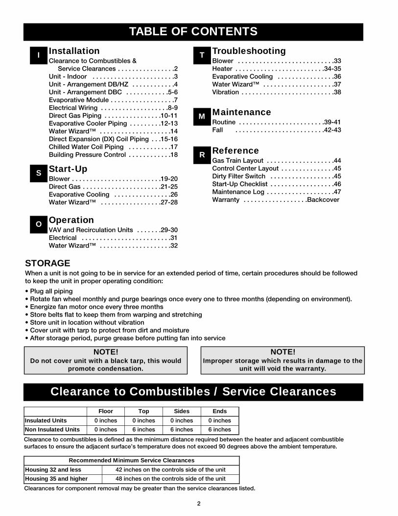
STORAGEWhen a unit is not going to be in service for an extended period of time, certain procedures should be followedto keep the unit in proper operating condition:
• Plug all piping• Rotate fan wheel monthly and purge bearings once every one to three months (depending on environment).• Energize fan motor once every three months• Store belts flat to keep them from warping and stretching• Store unit in location without vibration• Cover unit with tarp to protect from dirt and moisture• After storage period, purge grease before putting fan into service
NOTE!Do not cover unit with a black tarp, this would
promote condensation.
NOTE!Improper storage which results in damage to the
unit will void the warranty.
Clearance to Combustibles / Service Clearances
Floor Top Sides Ends
Insulated Units 0 inches 0 inches 0 inches 0 inches
Non Insulated Units 0 inches 6 inches 6 inches 6 inches
Clearance to combustibles is defined as the minimum distance required between the heater and adjacent combustiblesurfaces to ensure the adjacent surface’s temperature does not exceed 90 degrees above the ambient temperature.
Recommended Minimum Service Clearances
Housing 32 and less 42 inches on the controls side of the unit
Housing 35 and higher 48 inches on the controls side of the unit
Clearances for component removal may be greater than the service clearances listed.
3
Installation - Indoor InstallationInstallatio
n
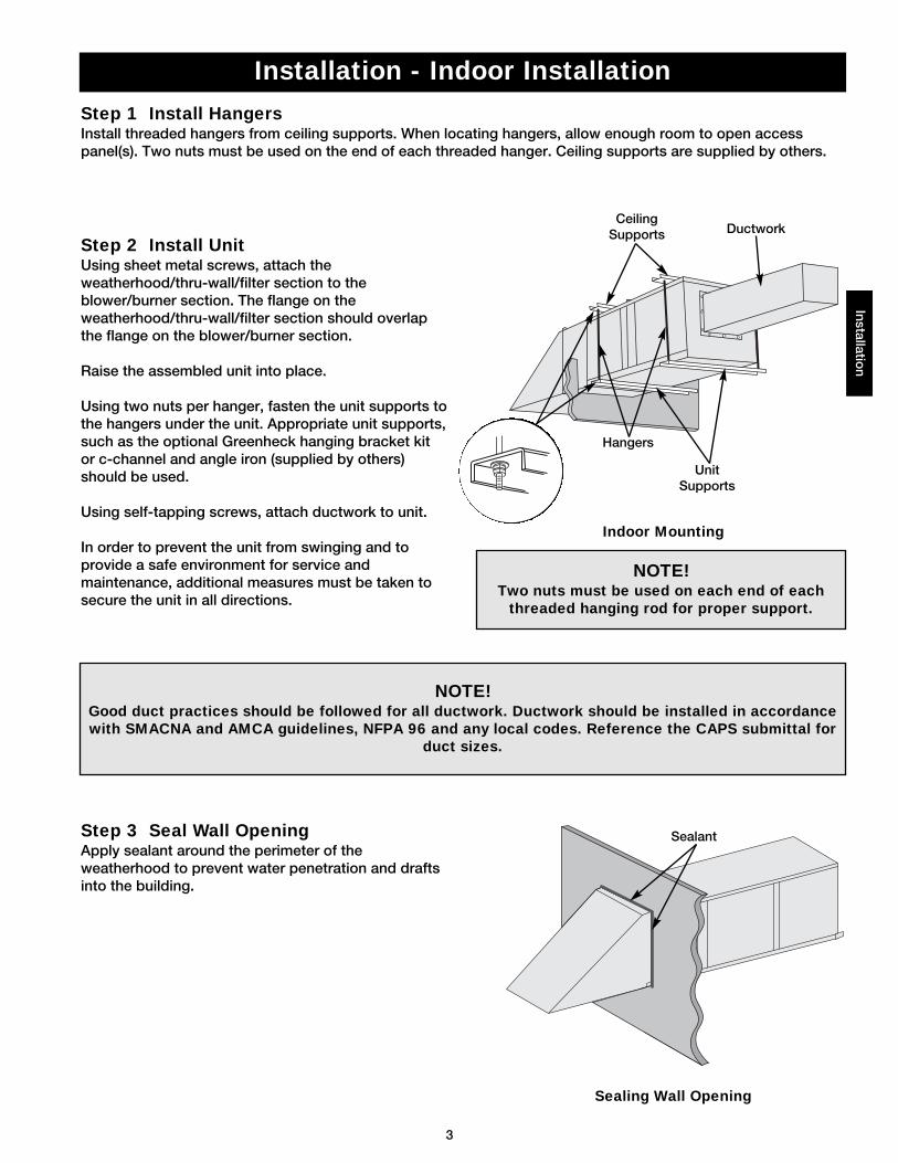
Step 1 Install HangersInstall threaded hangers from ceiling supports. When locating hangers, allow enough room to open accesspanel(s). Two nuts must be used on the end of each threaded hanger. Ceiling supports are supplied by others.
Step 2 Install UnitUsing sheet metal screws, attach theweatherhood/thru-wall/filter section to theblower/burner section. The flange on theweatherhood/thru-wall/filter section should overlapthe flange on the blower/burner section.
Raise the assembled unit into place.
Using two nuts per hanger, fasten the unit supports tothe hangers under the unit. Appropriate unit supports,such as the optional Greenheck hanging bracket kitor c-channel and angle iron (supplied by others)should be used.
Using self-tapping screws, attach ductwork to unit.
In order to prevent the unit from swinging and toprovide a safe environment for service andmaintenance, additional measures must be taken tosecure the unit in all directions.
Step 3 Seal Wall OpeningApply sealant around the perimeter of theweatherhood to prevent water penetration and draftsinto the building.
NOTE!Two nuts must be used on each end of each
threaded hanging rod for proper support.
NOTE!Good duct practices should be followed for all ductwork. Ductwork should be installed in accordancewith SMACNA and AMCA guidelines, NFPA 96 and any local codes. Reference the CAPS submittal for
duct sizes.
Sealant
UnitSupports
CeilingSupports
Hangers
Ductwork
Indoor Mounting
Sealing Wall Opening
4
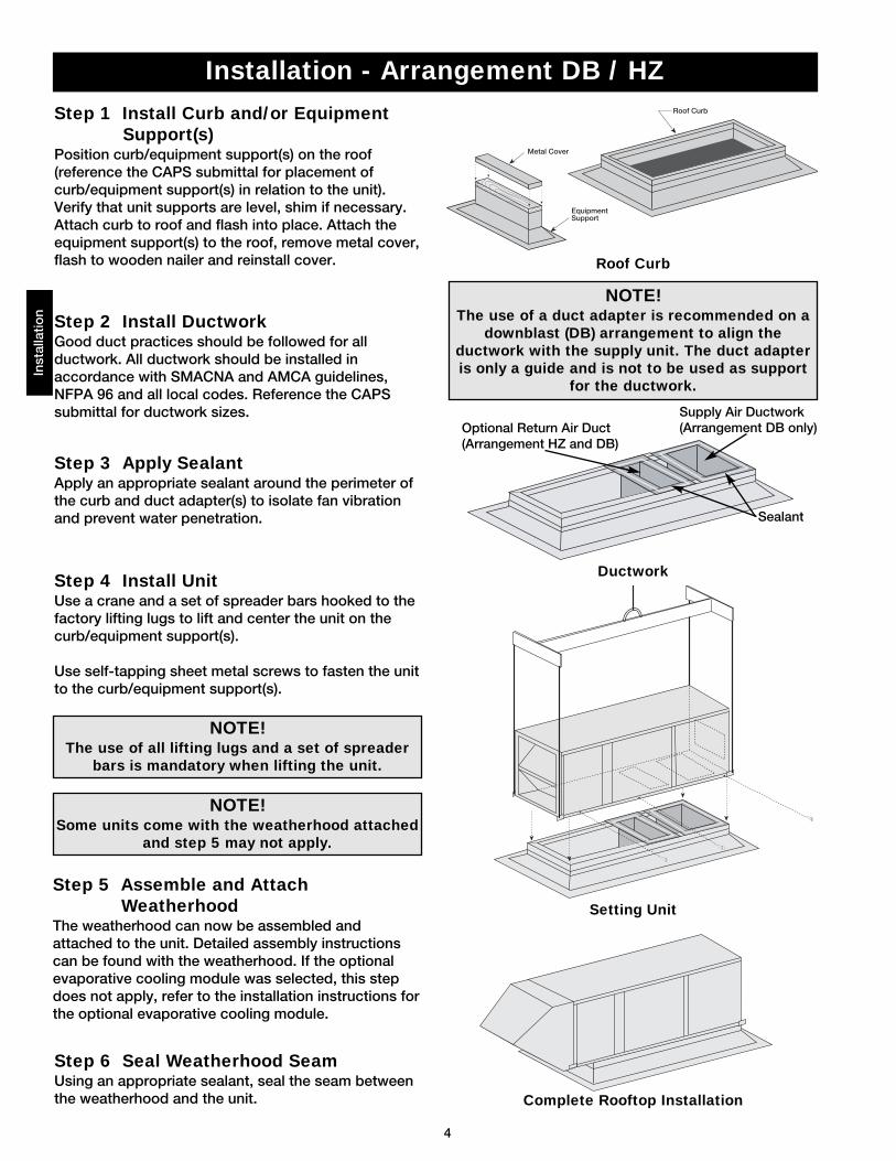
Step 6 Seal Weatherhood SeamUsing an appropriate sealant, seal the seam betweenthe weatherhood and the unit.
Step 3 Apply SealantApply an appropriate sealant around the perimeter ofthe curb and duct adapter(s) to isolate fan vibrationand prevent water penetration.
Step 1 Install Curb and/or EquipmentSupport(s)
Position curb/equipment support(s) on the roof(reference the CAPS submittal for placement ofcurb/equipment support(s) in relation to the unit).Verify that unit supports are level, shim if necessary.Attach curb to roof and flash into place. Attach theequipment support(s) to the roof, remove metal cover,flash to wooden nailer and reinstall cover.
Step 2 Install DuctworkGood duct practices should be followed for allductwork. All ductwork should be installed inaccordance with SMACNA and AMCA guidelines,NFPA 96 and all local codes. Reference the CAPSsubmittal for ductwork sizes.
Step 4 Install UnitUse a crane and a set of spreader bars hooked to thefactory lifting lugs to lift and center the unit on thecurb/equipment support(s).
Use self-tapping sheet metal screws to fasten the unitto the curb/equipment support(s).
Step 5 Assemble and AttachWeatherhood
The weatherhood can now be assembled andattached to the unit. Detailed assembly instructionscan be found with the weatherhood. If the optionalevaporative cooling module was selected, this stepdoes not apply, refer to the installation instructions forthe optional evaporative cooling module.
Supply Air Ductwork(Arrangement DB only)Optional Return Air Duct
(Arrangement HZ and DB)
Sealant
Installation - Arrangement DB / HZIn
stal
latio
n
NOTE! The use of all lifting lugs and a set of spreader
bars is mandatory when lifting the unit.
NOTE! Some units come with the weatherhood attached
and step 5 may not apply.
NOTE!The use of a duct adapter is recommended on a
downblast (DB) arrangement to align theductwork with the supply unit. The duct adapteris only a guide and is not to be used as support
for the ductwork.
Metal Cover
EquipmentSupport
Roof Curb
Roof Curb
Ductwork
Setting Unit
Complete Rooftop Installation
5
Supply Duct with DuctAdapter Installed
Exhaust Duct Installed
Sealant
SupplyDuctworkby Others
ExhaustDuctworkby Others
Metal Cover
EquipmentSupport
Roof Curb
Exhaust
Supply
1 inch InsideFlange
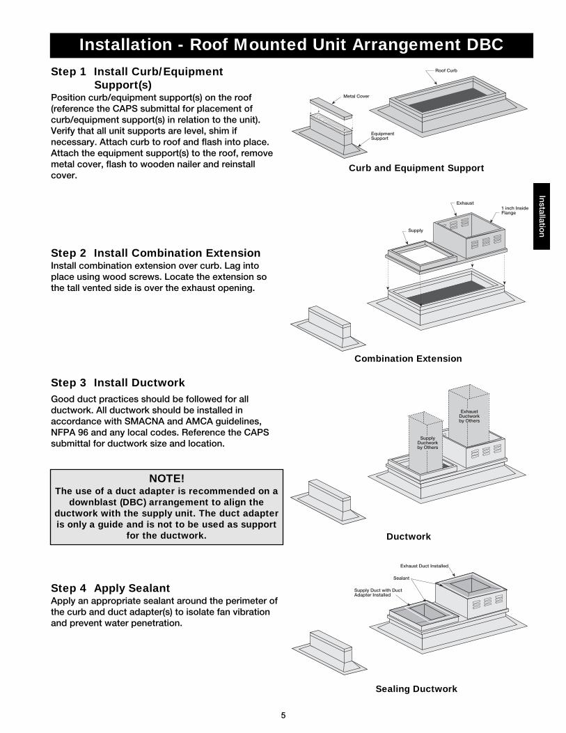
Step 1 Install Curb/EquipmentSupport(s)
Position curb/equipment support(s) on the roof(reference the CAPS submittal for placement ofcurb/equipment support(s) in relation to the unit).Verify that all unit supports are level, shim ifnecessary. Attach curb to roof and flash into place.Attach the equipment support(s) to the roof, removemetal cover, flash to wooden nailer and reinstallcover.
Step 2 Install Combination Extension Install combination extension over curb. Lag intoplace using wood screws. Locate the extension sothe tall vented side is over the exhaust opening.
Installation - Roof Mounted Unit Arrangement DBCInstallatio
n
Step 4 Apply SealantApply an appropriate sealant around the perimeter ofthe curb and duct adapter(s) to isolate fan vibrationand prevent water penetration.
NOTE!The use of a duct adapter is recommended on a
downblast (DBC) arrangement to align theductwork with the supply unit. The duct adapteris only a guide and is not to be used as support
for the ductwork.
Step 3 Install DuctworkGood duct practices should be followed for allductwork. All ductwork should be installed inaccordance with SMACNA and AMCA guidelines,NFPA 96 and any local codes. Reference the CAPSsubmittal for ductwork size and location.
Curb and Equipment Support
Combination Extension
Ductwork
Sealing Ductwork
6
Model CUBEExhaust Fan
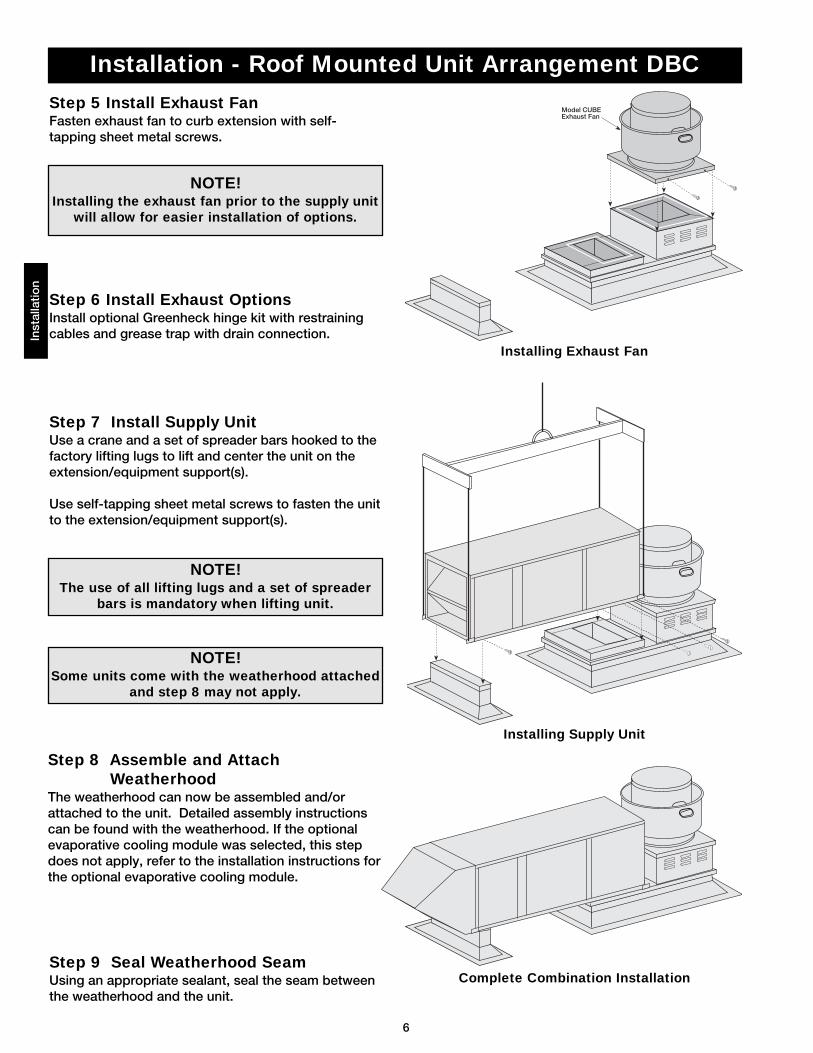
Step 5 Install Exhaust FanFasten exhaust fan to curb extension with self-tapping sheet metal screws.
Step 6 Install Exhaust OptionsInstall optional Greenheck hinge kit with restrainingcables and grease trap with drain connection.
Step 7 Install Supply UnitUse a crane and a set of spreader bars hooked to thefactory lifting lugs to lift and center the unit on theextension/equipment support(s).
Use self-tapping sheet metal screws to fasten the unitto the extension/equipment support(s).
Installation - Roof Mounted Unit Arrangement DBC
Step 8 Assemble and AttachWeatherhood
The weatherhood can now be assembled and/orattached to the unit. Detailed assembly instructionscan be found with the weatherhood. If the optionalevaporative cooling module was selected, this stepdoes not apply, refer to the installation instructions forthe optional evaporative cooling module.
Inst
alla
tion
NOTE!Installing the exhaust fan prior to the supply unit
will allow for easier installation of options.
NOTE!The use of all lifting lugs and a set of spreader
bars is mandatory when lifting unit.
Step 9 Seal Weatherhood SeamUsing an appropriate sealant, seal the seam betweenthe weatherhood and the unit.
NOTE! Some units come with the weatherhood attached
and step 8 may not apply.
Installing Exhaust Fan
Installing Supply Unit
Complete Combination Installation
7
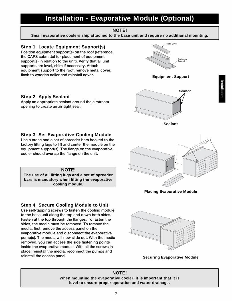
NOTE!When mounting the evaporative cooler, it is important that it is
level to ensure proper operation and water drainage.
Installation - Evaporative Module (Optional)Installatio
n
Step 1 Locate Equipment Support(s)Position equipment support(s) on the roof (referencethe CAPS submittal for placement of equipmentsupport(s) in relation to the unit). Verify that all unitsupports are level, shim if necessary. Attachequipment support to the roof, remove metal cover,flash to wooden nailer and reinstall cover.
Step 2 Apply SealantApply an appropriate sealant around the airstreamopening to create an air tight seal.
Step 3 Set Evaporative Cooling ModuleUse a crane and a set of spreader bars hooked to thefactory lifting lugs to lift and center the module on theequipment support(s). The flange on the evaporativecooler should overlap the flange on the unit.
Step 4 Secure Cooling Module to UnitUse self-tapping screws to fasten the cooling moduleto the base unit along the top and down both sides.Fasten at the top through the flanges. To fasten thesides, the media must be removed. To remove themedia, first remove the access panel on theevaporative module and disconnect the evaporativepump(s). The media will now slide out. With the mediaremoved, you can access the side fastening pointsinside the evaporative module. With all the screws inplace, reinstall the media, reconnect the pumps andreinstall the access panel.
NOTE!Small evaporative coolers ship attached to the base unit and require no additional mounting.
NOTE!The use of all lifting lugs and a set of spreaderbars is mandatory when lifting the evaporative
cooling module.
Metal Cover
EquipmentSupport
Sealant
Equipment Support
Sealant
Placing Evaporative Module
Securing Evaporative Module
8
Step 4 Wire the Optional Convenience OutletThe convenience outlet requires a separate 115V power supply circuit. The circuit must include short circuitprotection which may need to be supplied by others.
Step 3 Connect the Main PowerConnect the main power lines to the disconnect switch and main grounding lug(s). Torque field connections to20 in-lbs. See the control center layout in the reference section for main disconnect and grounding lug(s)locations.
Installation - Electrical Wiring
CAUTION!If replacement wire is required, it must have a
temperature rating of at least 105°C, except forenergy cut-off or sensor lead wire which must be
rated to 150°C.
CAUTION!Any wiring deviations may result in personal injury or property damage. Greenheck is not responsible
for any damage to, or failure of the unit caused by incorrect final wiring.
Inst
alla
tion
DANGER!High voltage electrical input is needed for this
equipment. This work should be performed by aqualified electrician.
IMPORTANT!All wiring should be done in accordance with the
latest edition of the National Electrical CodeANSI/NFPA-70 and any local codes that mayapply. In Canada, wiring should be done in
accordance with the Canadian Electrical Code.
IMPORTANT!The equipment must be properly grounded.Any wiring running through the unit in the
airstream must be protected by metal conduit,metal clad cable or raceways.
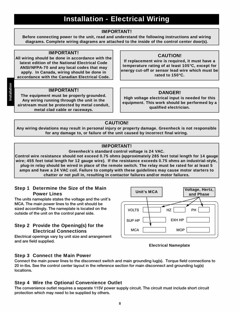
Step 1 Determine the Size of the MainPower Lines
The units nameplate states the voltage and the unit’sMCA. The main power lines to the unit should besized accordingly. The nameplate is located on theoutside of the unit on the control panel side.
Step 2 Provide the Opening(s) for theElectrical Connections
Electrical openings vary by unit size and arrangementand are field supplied.
Voltage, Hertz,and Phase
Unit’s MCA
IMPORTANT!Before connecting power to the unit, read and understand the following instructions and wiring
diagrams. Complete wiring diagrams are attached to the inside of the control center door(s).
IMPORTANT!Greenheck’s standard control voltage is 24 VAC.
Control wire resistance should not exceed 0.75 ohms (approximately 285 feet total length for 14 gaugewire; 455 feet total length for 12 gauge wire). If the resistance exceeds 0.75 ohms an industrial-style,
plug-in relay should be wired in place of the remote switch. The relay must be rated for at least 5amps and have a 24 VAC coil. Failure to comply with these guidelines may cause motor starters to
chatter or not pull in, resulting in contactor failures and/or motor failures.
Electrical Nameplate
SUP HP
MCA
EXH HP
MOP
VOLTS HZ PH
9
Step 5 Wire the AccessoriesReference the ladder diagram on the inside of thecontrol center door for correct wiring of the followingaccessories:
Step 6 Wire the Optional EvaporativeCooler
Reference the ladder diagram on the inside of thecontrol center door for correct wiring of the pump andthe optional auto-drain and flush.
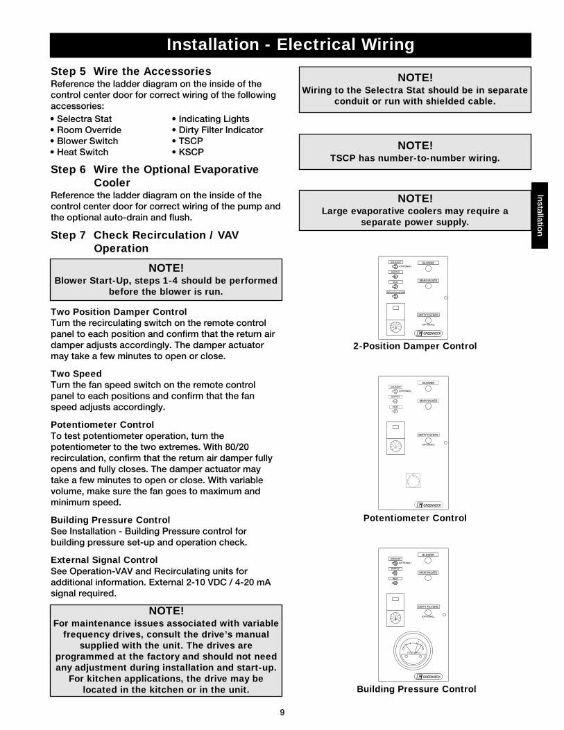
Step 7 Check Recirculation / VAVOperation
Two Position Damper ControlTurn the recirculating switch on the remote controlpanel to each position and confirm that the return airdamper adjusts accordingly. The damper actuatormay take a few minutes to open or close.
Two SpeedTurn the fan speed switch on the remote controlpanel to each positions and confirm that the fanspeed adjusts accordingly.
Potentiometer ControlTo test potentiometer operation, turn thepotentiometer to the two extremes. With 80/20recirculation, confirm that the return air damper fullyopens and fully closes. The damper actuator maytake a few minutes to open or close. With variablevolume, make sure the fan goes to maximum andminimum speed.
Building Pressure ControlSee Installation - Building Pressure control forbuilding pressure set-up and operation check.
External Signal ControlSee Operation-VAV and Recirculating units foradditional information. External 2-10 VDC / 4-20 mAsignal required.
NOTE! Large evaporative coolers may require a
separate power supply.
NOTE! TSCP has number-to-number wiring.
NOTE! Wiring to the Selectra Stat should be in separate
conduit or run with shielded cable.
Installation - Electrical WiringInstallatio
n
NOTE!For maintenance issues associated with variable
frequency drives, consult the drive’s manualsupplied with the unit. The drives are
programmed at the factory and should not needany adjustment during installation and start-up.
For kitchen applications, the drive may belocated in the kitchen or in the unit.
NOTE!Blower Start-Up, steps 1-4 should be performed
before the blower is run.
• Selectra Stat• Room Override• Blower Switch• Heat Switch
• Indicating Lights• Dirty Filter Indicator • TSCP• KSCP
7065
75
80
85
90
60
55
(OPTIONAL)
BLOWER
DIRTY FILTERS
MAIN VALVES
EXHAUST
SUPPLY
HEAT
(OPTIONAL)
GREENHECK®
PHOTOHELIC
7065
75
80
85
90
60
55
(OPTIONAL)
BLOWER
DIRTY FILTERS
MAIN VALVES
EXHAUST
SUPPLY
HEAT
(OPTIONAL)
GREENHECK®
7065
75
80
85
90
60
55
GREENHECK®
(OPTIONAL)
BLOWER
DIRTY FILTERS
MAIN VALVES
RECIRCULATION
EXHAUST
SUPPLY
HEAT
(OPTIONAL)
2-Position Damper Control
Potentiometer Control
Building Pressure Control
10
Installation - Direct Gas PipingIn
stal
latio
n
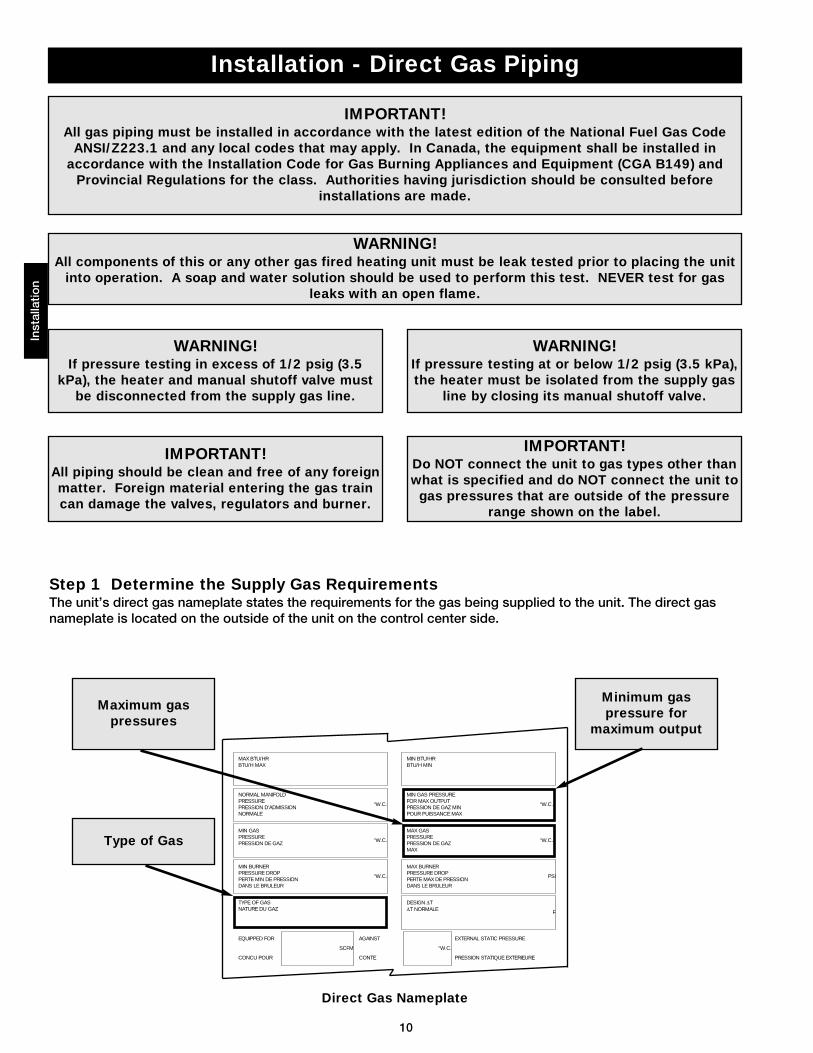
Step 1 Determine the Supply Gas RequirementsThe unit’s direct gas nameplate states the requirements for the gas being supplied to the unit. The direct gasnameplate is located on the outside of the unit on the control center side.
IMPORTANT!All gas piping must be installed in accordance with the latest edition of the National Fuel Gas Code
ANSI/Z223.1 and any local codes that may apply. In Canada, the equipment shall be installed inaccordance with the Installation Code for Gas Burning Appliances and Equipment (CGA B149) and
Provincial Regulations for the class. Authorities having jurisdiction should be consulted beforeinstallations are made.
WARNING!All components of this or any other gas fired heating unit must be leak tested prior to placing the unit
into operation. A soap and water solution should be used to perform this test. NEVER test for gasleaks with an open flame.
WARNING!If pressure testing in excess of 1/2 psig (3.5
kPa), the heater and manual shutoff valve mustbe disconnected from the supply gas line.
WARNING!If pressure testing at or below 1/2 psig (3.5 kPa),the heater must be isolated from the supply gas
line by closing its manual shutoff valve.
IMPORTANT!All piping should be clean and free of any foreignmatter. Foreign material entering the gas traincan damage the valves, regulators and burner.
“W.C.
“W.C.
“W.C.
F
PSI
“W.C.
“W.C.
MAX BTU/HRBTU/H MAX
NORMAL MANIFOLDPRESSUREPRESSION D’ADMISSIONNORMALE
MIN GASPRESSUREPRESSION DE GAZ
MIN BURNERPRESSURE DROPPERTE MIN DE PRESSIONDANS LE BRULEUR
TYPE OF GASNATURE DU GAZ
MIN BTU/HRBTU/H MIN
MIN GAS PRESSUREFOR MAX OUTPUTPRESSION DE GAZ MINPOUR PUISSANCE MAX
MAX BURNERPRESSURE DROPPERTE MAX DE PRESSIONDANS LE BRULEUR
MAX GASPRESSUREPRESSION DE GAZMAX
DESIGN ∆T∆T NORMALE
EQUIPPED FOR
CONCU POUR
SCFM “W.C.
EXTERNAL STATIC PRESSURE
PRESSION STATIQUE EXTERIEURE
AGAINST
CONTE
Maximum gaspressures
Minimum gaspressure for
maximum output
Type of Gas
IMPORTANT!Do NOT connect the unit to gas types other thanwhat is specified and do NOT connect the unit togas pressures that are outside of the pressure
range shown on the label.
Direct Gas Nameplate
11
Installation - Direct Gas PipingInstallatio
n
ToControls
Gas Cock
FromGas
Supply
6 in. Trap
1/8 in. Plugged Tap
Ground Joint Union
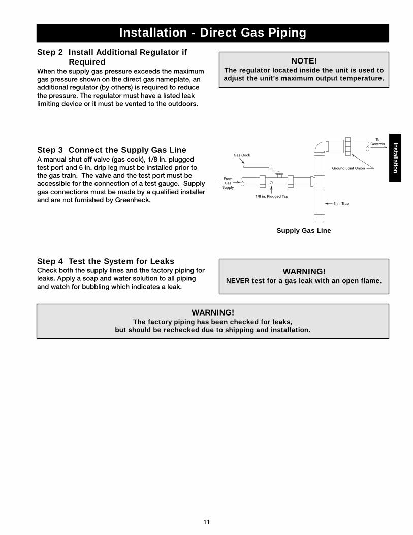
Step 3 Connect the Supply Gas LineA manual shut off valve (gas cock), 1/8 in. pluggedtest port and 6 in. drip leg must be installed prior tothe gas train. The valve and the test port must beaccessible for the connection of a test gauge. Supplygas connections must be made by a qualified installerand are not furnished by Greenheck.
Step 2 Install Additional Regulator ifRequired
When the supply gas pressure exceeds the maximumgas pressure shown on the direct gas nameplate, anadditional regulator (by others) is required to reducethe pressure. The regulator must have a listed leaklimiting device or it must be vented to the outdoors.
Step 4 Test the System for LeaksCheck both the supply lines and the factory piping forleaks. Apply a soap and water solution to all pipingand watch for bubbling which indicates a leak.
WARNING!The factory piping has been checked for leaks,
but should be rechecked due to shipping and installation.
WARNING!NEVER test for a gas leak with an open flame.
NOTE!The regulator located inside the unit is used toadjust the unit’s maximum output temperature.
Supply Gas Line
12
Installation - Evaporative Cooling Piping (Optional)
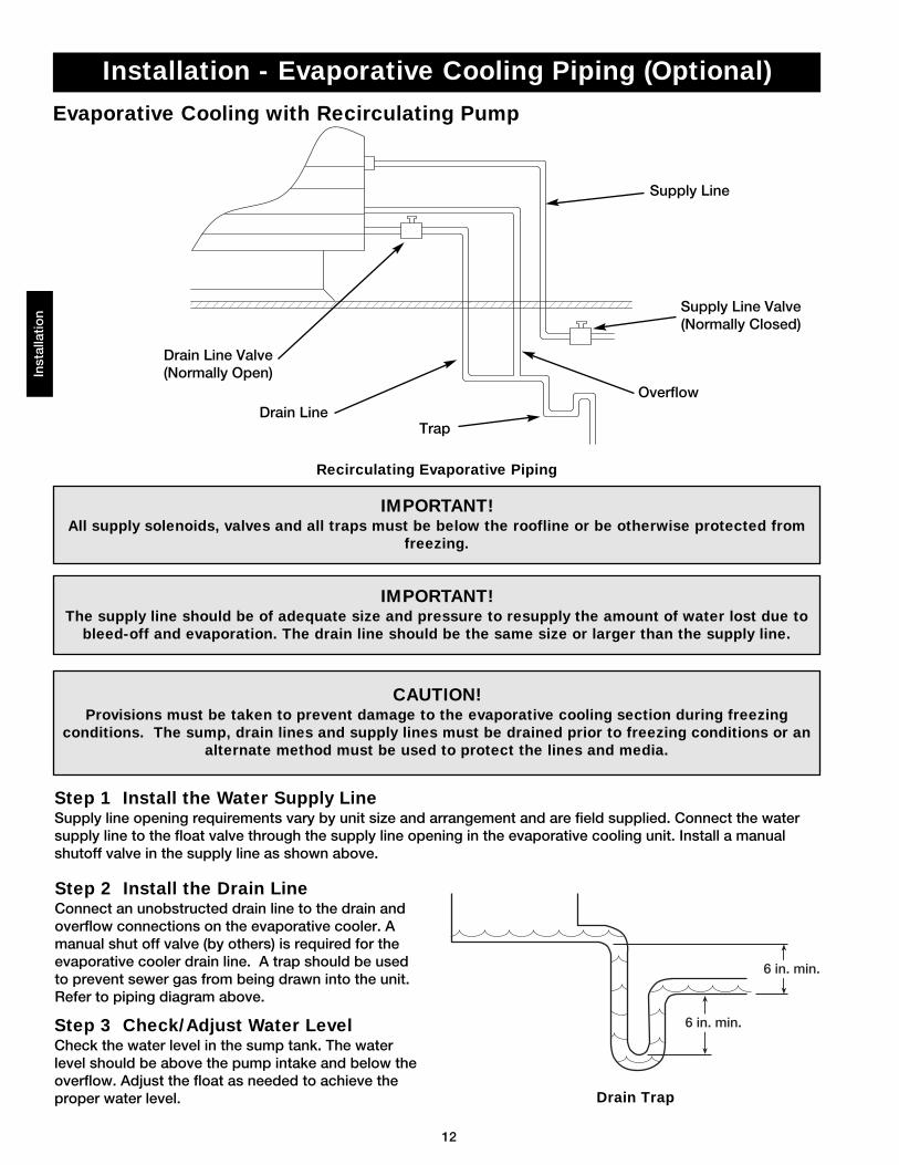
Evaporative Cooling with Recirculating Pump
Inst
alla
tion
IMPORTANT!The supply line should be of adequate size and pressure to resupply the amount of water lost due to
bleed-off and evaporation. The drain line should be the same size or larger than the supply line.
Step 1 Install the Water Supply LineSupply line opening requirements vary by unit size and arrangement and are field supplied. Connect the watersupply line to the float valve through the supply line opening in the evaporative cooling unit. Install a manualshutoff valve in the supply line as shown above.
Step 2 Install the Drain LineConnect an unobstructed drain line to the drain andoverflow connections on the evaporative cooler. Amanual shut off valve (by others) is required for theevaporative cooler drain line. A trap should be usedto prevent sewer gas from being drawn into the unit.Refer to piping diagram above.
Step 3 Check/Adjust Water LevelCheck the water level in the sump tank. The waterlevel should be above the pump intake and below theoverflow. Adjust the float as needed to achieve theproper water level.
CAUTION!Provisions must be taken to prevent damage to the evaporative cooling section during freezing
conditions. The sump, drain lines and supply lines must be drained prior to freezing conditions or analternate method must be used to protect the lines and media.
IMPORTANT!All supply solenoids, valves and all traps must be below the roofline or be otherwise protected from
freezing.
6 in. min.
6 in. min.
Supply Line
Overflow
Trap
Drain Line Valve(Normally Open)
Drain Line
Supply Line Valve(Normally Closed)
Recirculating Evaporative Piping
Drain Trap
13
Installation - Evaporative Cooler Piping (Optional)Installatio
n
IMPORTANT!The supply line should be of adequate size and pressure to resupply the amount of water lost due to
bleed-off and evaporation. The drain line should be the same size or larger than the supply line.
CAUTION!All solenoids valves and traps must be installedbelow the roof to protect the supply water linefrom freezing. If they cannot be installed belowthe roof, an alternative method must be used to
protect the lines from freezing
IMPORTANT!The supply solenoid (Valve A) is NOT the same asthe drain solenoids (Valve B and Valve C). Make
sure to use the proper solenoid for eachlocation. Check you local code requirements for
proper installation of this type of system.
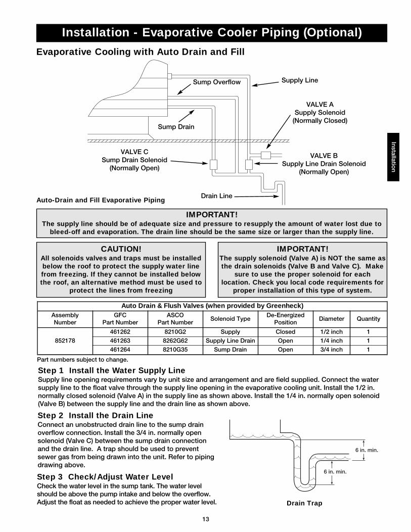
Step 1 Install the Water Supply LineSupply line opening requirements vary by unit size and arrangement and are field supplied. Connect the watersupply line to the float valve through the supply line opening in the evaporative cooling unit. Install the 1/2 in.normally closed solenoid (Valve A) in the supply line as shown above. Install the 1/4 in. normally open solenoid(Valve B) between the supply line and the drain line as shown above.
Step 2 Install the Drain LineConnect an unobstructed drain line to the sump drainoverflow connection. Install the 3/4 in. normally opensolenoid (Valve C) between the sump drain connectionand the drain line. A trap should be used to preventsewer gas from being drawn into the unit. Refer to pipingdrawing above.
Evaporative Cooling with Auto Drain and Fill
Step 3 Check/Adjust Water LevelCheck the water level in the sump tank. The water levelshould be above the pump intake and below the overflow.Adjust the float as needed to achieve the proper water level.
6 in. min.
6 in. min.
Auto-Drain and Fill Evaporative Piping
Drain Trap
Auto Drain & Flush Valves (when provided by Greenheck)AssemblyNumber
GFCPart Number
ASCOPart Number
Solenoid TypeDe-Energized
PositionDiameter Quantity
852178
461262 8210G2 Supply Closed 1/2 inch 1
461263 8262G62 Supply Line Drain Open 1/4 inch 1
461264 8210G35 Sump Drain Open 3/4 inch 1
Supply Line
VALVE BSupply Line Drain Solenoid
(Normally Open)
Sump Overflow
Sump Drain
VALVE CSump Drain Solenoid
(Normally Open)
VALVE ASupply Solenoid
(Normally Closed)
Drain Line
Part numbers subject to change.
14
Inst
alla
tion
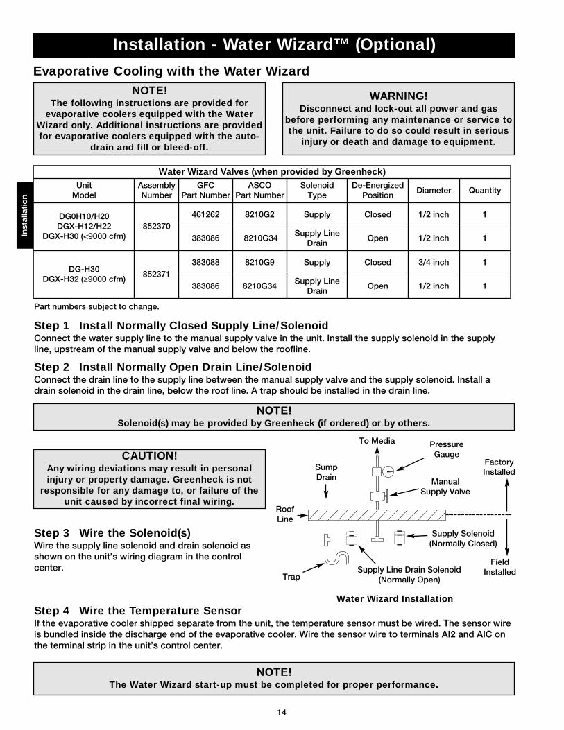
Evaporative Cooling with the Water Wizard
Installation - Water Wizard™ (Optional)
Step 3 Wire the Solenoid(s)Wire the supply line solenoid and drain solenoid asshown on the unit’s wiring diagram in the controlcenter.
Step 4 Wire the Temperature SensorIf the evaporative cooler shipped separate from the unit, the temperature sensor must be wired. The sensor wireis bundled inside the discharge end of the evaporative cooler. Wire the sensor wire to terminals AI2 and AIC onthe terminal strip in the unit’s control center.
Step 1 Install Normally Closed Supply Line/SolenoidConnect the water supply line to the manual supply valve in the unit. Install the supply solenoid in the supplyline, upstream of the manual supply valve and below the roofline.
Step 2 Install Normally Open Drain Line/SolenoidConnect the drain line to the supply line between the manual supply valve and the supply solenoid. Install adrain solenoid in the drain line, below the roof line. A trap should be installed in the drain line.
CAUTION!Any wiring deviations may result in personalinjury or property damage. Greenheck is not
responsible for any damage to, or failure of theunit caused by incorrect final wiring.
NOTE!The Water Wizard start-up must be completed for proper performance.
NOTE!Solenoid(s) may be provided by Greenheck (if ordered) or by others.
WARNING!Disconnect and lock-out all power and gas
before performing any maintenance or service tothe unit. Failure to do so could result in serious
injury or death and damage to equipment.
NOTE!The following instructions are provided for
evaporative coolers equipped with the WaterWizard only. Additional instructions are providedfor evaporative coolers equipped with the auto-
drain and fill or bleed-off.
Water Wizard Valves (when provided by Greenheck)Unit
ModelAssemblyNumber
GFCPart Number
ASCOPart Number
SolenoidType
De-EnergizedPosition
Diameter Quantity
DG0H10/H20DGX-H12/H22
DGX-H30 (<9000 cfm)852370
461262 8210G2 Supply Closed 1/2 inch 1
383086 8210G34Supply Line
DrainOpen 1/2 inch 1
DG-H30DGX-H32 (≥9000 cfm)
852371383088 8210G9 Supply Closed 3/4 inch 1
383086 8210G34Supply Line
DrainOpen 1/2 inch 1
Supply Line Drain Solenoid(Normally Open)
Supply Solenoid(Normally Closed)
ManualSupply Valve
PressureGauge
To Media
SumpDrain
RoofLine
Trap
Water Wizard Installation
FactoryInstalled
FieldInstalled
Part numbers subject to change.
15
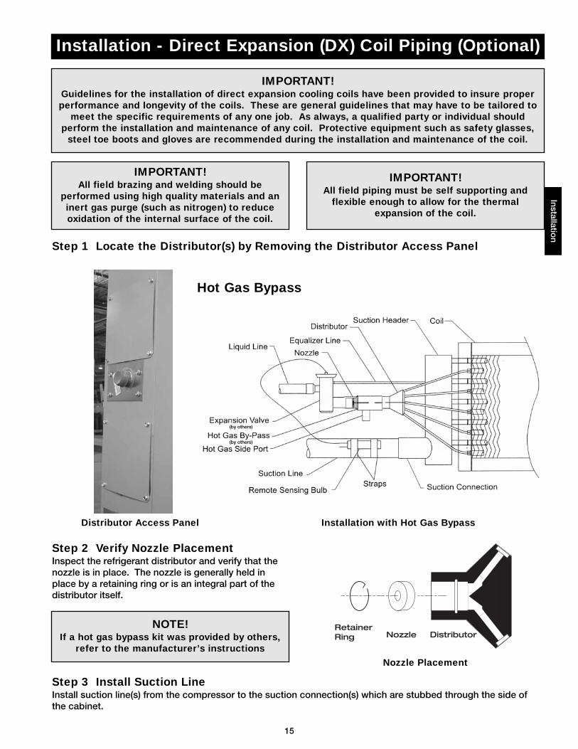
Installation - Direct Expansion (DX) Coil Piping (Optional)Installatio
n
IMPORTANT!Guidelines for the installation of direct expansion cooling coils have been provided to insure properperformance and longevity of the coils. These are general guidelines that may have to be tailored to
meet the specific requirements of any one job. As always, a qualified party or individual shouldperform the installation and maintenance of any coil. Protective equipment such as safety glasses,
steel toe boots and gloves are recommended during the installation and maintenance of the coil.
IMPORTANT!All field brazing and welding should be
performed using high quality materials and aninert gas purge (such as nitrogen) to reduceoxidation of the internal surface of the coil.
IMPORTANT!All field piping must be self supporting and
flexible enough to allow for the thermalexpansion of the coil.
Hot Gas Bypass
(by others)
Step 1 Locate the Distributor(s) by Removing the Distributor Access Panel
(by others)
Installation with Hot Gas Bypass
Step 2 Verify Nozzle PlacementInspect the refrigerant distributor and verify that thenozzle is in place. The nozzle is generally held inplace by a retaining ring or is an integral part of thedistributor itself.
RetainerRing Nozzle Distributor
NOTE!If a hot gas bypass kit was provided by others,
refer to the manufacturer’s instructions
Nozzle Placement
Step 3 Install Suction LineInstall suction line(s) from the compressor to the suction connection(s) which are stubbed through the side ofthe cabinet.
Distributor Access Panel
16
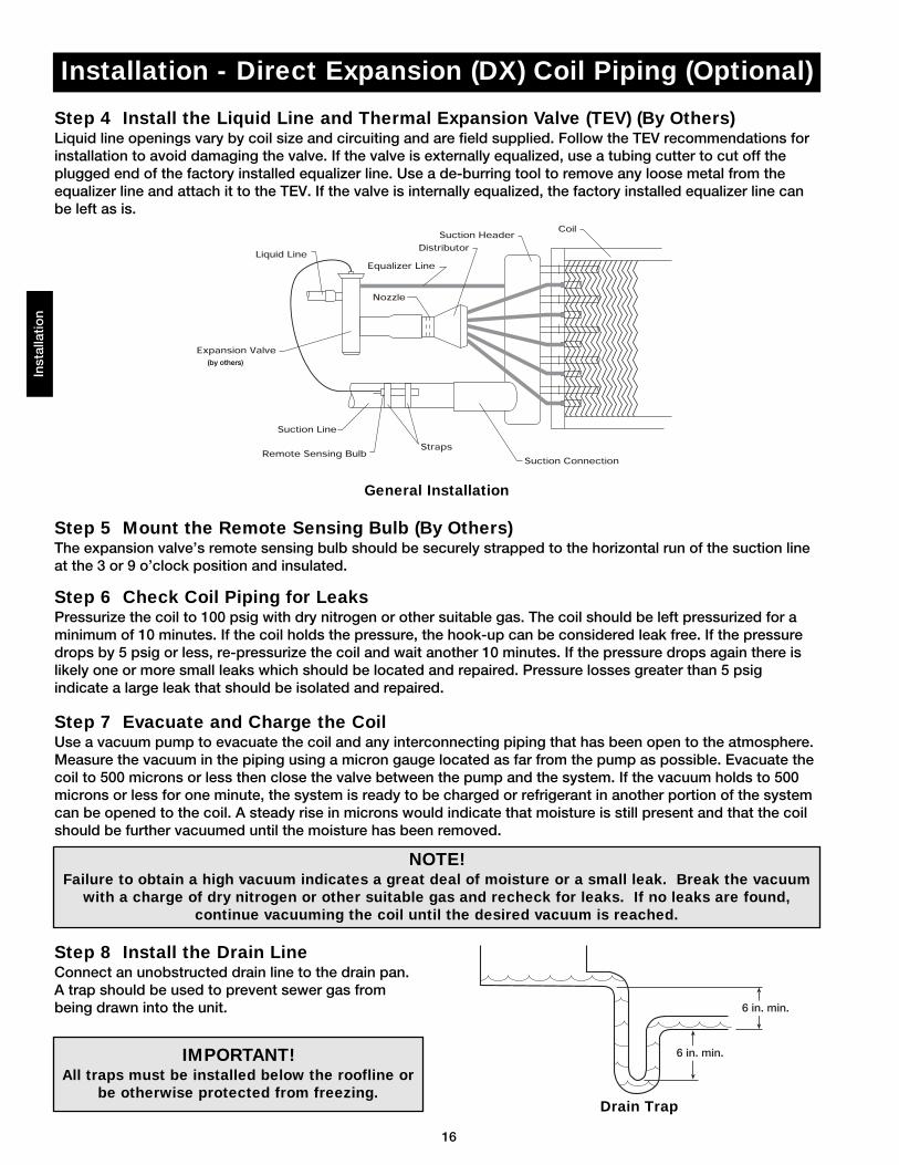
Installation - Direct Expansion (DX) Coil Piping (Optional)In
stal
latio
n
Step 7 Evacuate and Charge the CoilUse a vacuum pump to evacuate the coil and any interconnecting piping that has been open to the atmosphere.Measure the vacuum in the piping using a micron gauge located as far from the pump as possible. Evacuate thecoil to 500 microns or less then close the valve between the pump and the system. If the vacuum holds to 500microns or less for one minute, the system is ready to be charged or refrigerant in another portion of the systemcan be opened to the coil. A steady rise in microns would indicate that moisture is still present and that the coilshould be further vacuumed until the moisture has been removed.
6 in. min.
6 in. min.
Step 8 Install the Drain LineConnect an unobstructed drain line to the drain pan.A trap should be used to prevent sewer gas frombeing drawn into the unit.
NOTE! Failure to obtain a high vacuum indicates a great deal of moisture or a small leak. Break the vacuum
with a charge of dry nitrogen or other suitable gas and recheck for leaks. If no leaks are found,continue vacuuming the coil until the desired vacuum is reached.
Step 6 Check Coil Piping for LeaksPressurize the coil to 100 psig with dry nitrogen or other suitable gas. The coil should be left pressurized for aminimum of 10 minutes. If the coil holds the pressure, the hook-up can be considered leak free. If the pressuredrops by 5 psig or less, re-pressurize the coil and wait another 10 minutes. If the pressure drops again there islikely one or more small leaks which should be located and repaired. Pressure losses greater than 5 psigindicate a large leak that should be isolated and repaired.
Step 4 Install the Liquid Line and Thermal Expansion Valve (TEV) (By Others)Liquid line openings vary by coil size and circuiting and are field supplied. Follow the TEV recommendations forinstallation to avoid damaging the valve. If the valve is externally equalized, use a tubing cutter to cut off theplugged end of the factory installed equalizer line. Use a de-burring tool to remove any loose metal from theequalizer line and attach it to the TEV. If the valve is internally equalized, the factory installed equalizer line can be left as is.
Step 5 Mount the Remote Sensing Bulb (By Others)The expansion valve’s remote sensing bulb should be securely strapped to the horizontal run of the suction lineat the 3 or 9 o’clock position and insulated.
IMPORTANT!All traps must be installed below the roofline or
be otherwise protected from freezing.Drain Trap
CoilSuction Header
Distributor
Equalizer Line
Nozzle
Liquid Line
Expansion Valve
Suction Line
Remote Sensing BulbStraps
Suction Connection
General Installation
(by others)
17
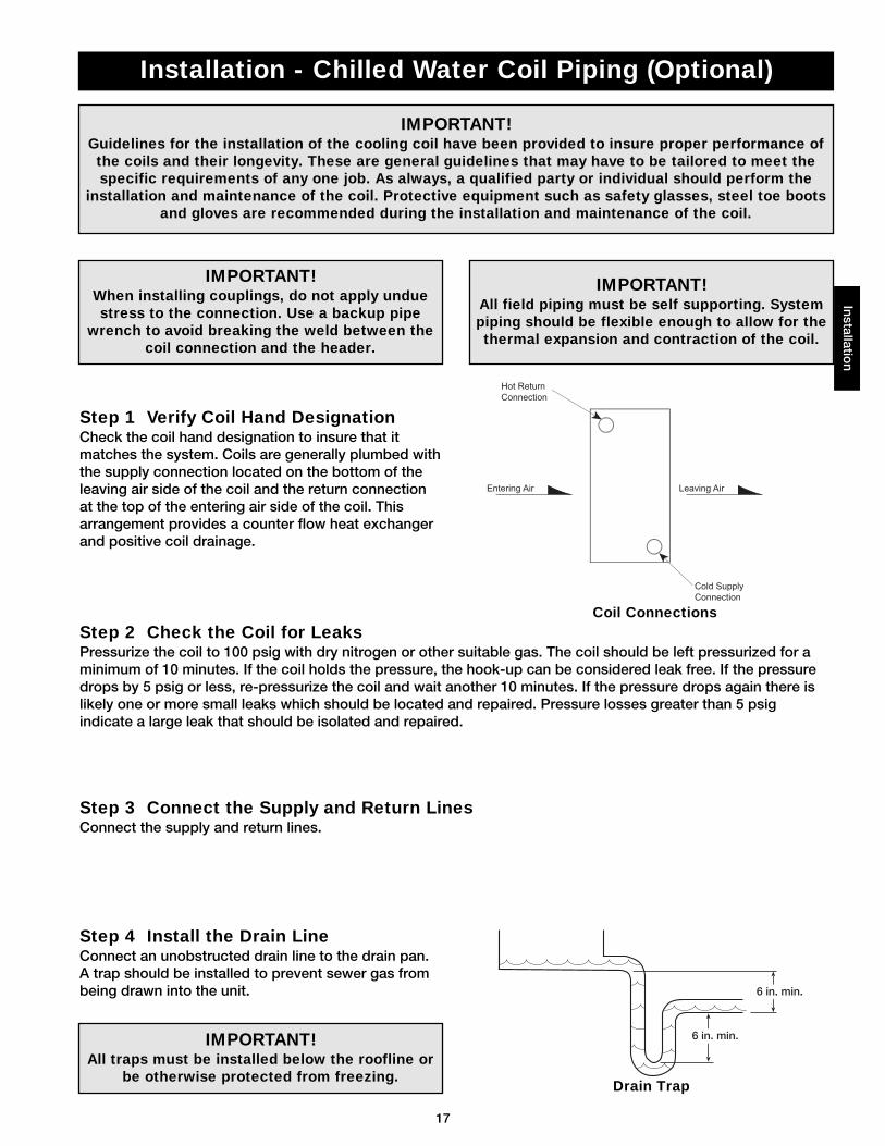
Step 1 Verify Coil Hand DesignationCheck the coil hand designation to insure that itmatches the system. Coils are generally plumbed withthe supply connection located on the bottom of theleaving air side of the coil and the return connectionat the top of the entering air side of the coil. Thisarrangement provides a counter flow heat exchangerand positive coil drainage.
Step 2 Check the Coil for LeaksPressurize the coil to 100 psig with dry nitrogen or other suitable gas. The coil should be left pressurized for aminimum of 10 minutes. If the coil holds the pressure, the hook-up can be considered leak free. If the pressuredrops by 5 psig or less, re-pressurize the coil and wait another 10 minutes. If the pressure drops again there islikely one or more small leaks which should be located and repaired. Pressure losses greater than 5 psigindicate a large leak that should be isolated and repaired.
Step 3 Connect the Supply and Return LinesConnect the supply and return lines.
Installation - Chilled Water Coil Piping (Optional)
IMPORTANT!Guidelines for the installation of the cooling coil have been provided to insure proper performance ofthe coils and their longevity. These are general guidelines that may have to be tailored to meet thespecific requirements of any one job. As always, a qualified party or individual should perform the
installation and maintenance of the coil. Protective equipment such as safety glasses, steel toe bootsand gloves are recommended during the installation and maintenance of the coil.
IMPORTANT!When installing couplings, do not apply unduestress to the connection. Use a backup pipe
wrench to avoid breaking the weld between thecoil connection and the header.
IMPORTANT!All field piping must be self supporting. Systempiping should be flexible enough to allow for thethermal expansion and contraction of the coil.
Step 4 Install the Drain LineConnect an unobstructed drain line to the drain pan.A trap should be installed to prevent sewer gas frombeing drawn into the unit.
Hot Return
Connection
Cold Supply
Connection
Entering Air Leaving Air
IMPORTANT!All traps must be installed below the roofline or
be otherwise protected from freezing.
6 in. min.
6 in. min.
Installation
Coil Connections
Drain Trap
18
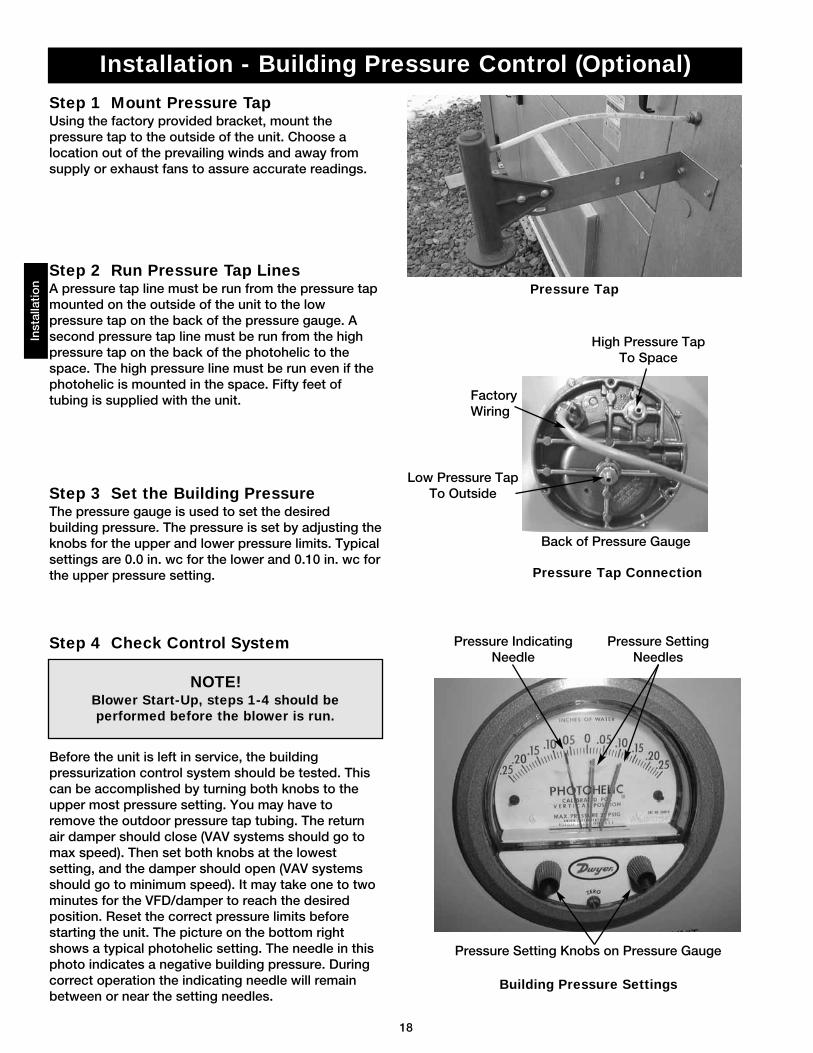
Step 1 Mount Pressure TapUsing the factory provided bracket, mount thepressure tap to the outside of the unit. Choose alocation out of the prevailing winds and away fromsupply or exhaust fans to assure accurate readings.
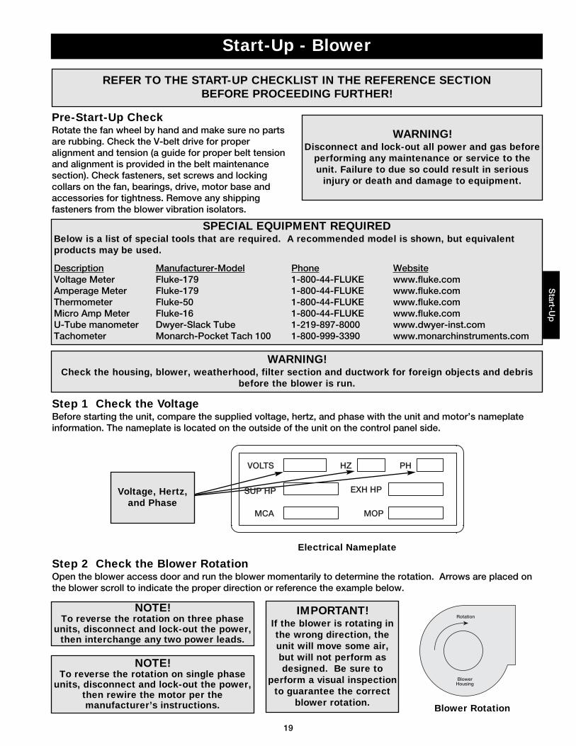
Step 2 Run Pressure Tap LinesA pressure tap line must be run from the pressure tapmounted on the outside of the unit to the lowpressure tap on the back of the pressure gauge. Asecond pressure tap line must be run from the highpressure tap on the back of the photohelic to thespace. The high pressure line must be run even if thephotohelic is mounted in the space. Fifty feet oftubing is supplied with the unit.
Step 3 Set the Building PressureThe pressure gauge is used to set the desiredbuilding pressure. The pressure is set by adjusting theknobs for the upper and lower pressure limits. Typicalsettings are 0.0 in. wc for the lower and 0.10 in. wc forthe upper pressure setting.
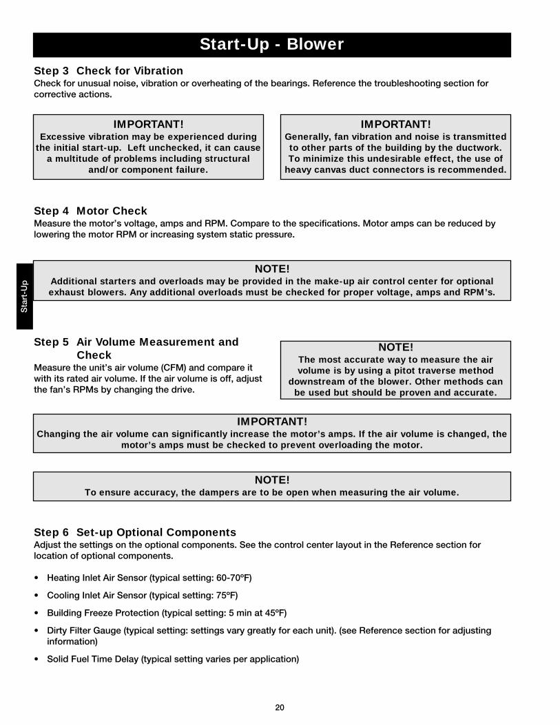
Step 4 Check Control System
Before the unit is left in service, the buildingpressurization control system should be tested. Thiscan be accomplished by turning both knobs to theupper most pressure setting. You may have toremove the outdoor pressure tap tubing. The returnair damper should close (VAV systems should go tomax speed). Then set both knobs at the lowestsetting, and the damper should open (VAV systemsshould go to minimum speed). It may take one to twominutes for the VFD/damper to reach the desiredposition. Reset the correct pressure limits beforestarting the unit. The picture on the bottom rightshows a typical photohelic setting. The needle in thisphoto indicates a negative building pressure. Duringcorrect operation the indicating needle will remainbetween or near the setting needles.
Installation - Building Pressure Control (Optional)
Low Pressure TapTo Outside
High Pressure TapTo Space
FactoryWiring
Pressure Setting Knobs on Pressure Gauge
Pressure SettingNeedles
Pressure IndicatingNeedle
Inst
alla
tion
NOTE!Blower Start-Up, steps 1-4 should beperformed before the blower is run.
Pressure Tap
Building Pressure Settings
Pressure Tap Connection
Back of Pressure Gauge
19
Start-Up - BlowerS
tart-Up
Voltage, Hertz,and Phase
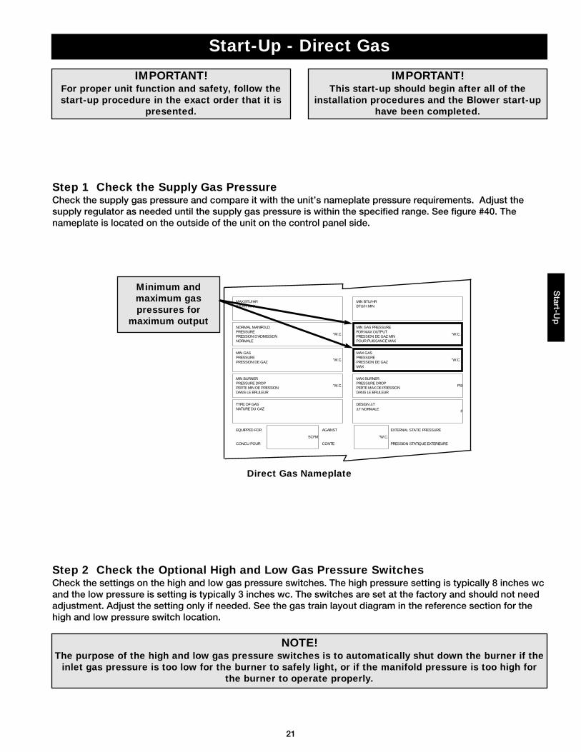
Step 1 Check the VoltageBefore starting the unit, compare the supplied voltage, hertz, and phase with the unit and motor’s nameplateinformation. The nameplate is located on the outside of the unit on the control panel side.
Step 2 Check the Blower RotationOpen the blower access door and run the blower momentarily to determine the rotation. Arrows are placed onthe blower scroll to indicate the proper direction or reference the example below.
IMPORTANT!If the blower is rotating inthe wrong direction, theunit will move some air,but will not perform asdesigned. Be sure to
perform a visual inspectionto guarantee the correct
blower rotation.
Blower
Rotation
Housing
SPECIAL EQUIPMENT REQUIREDBelow is a list of special tools that are required. A recommended model is shown, but equivalentproducts may be used.
Description Manufacturer-Model Phone WebsiteVoltage Meter Fluke-179 1-800-44-FLUKE www.fluke.comAmperage Meter Fluke-179 1-800-44-FLUKE www.fluke.comThermometer Fluke-50 1-800-44-FLUKE www.fluke.comMicro Amp Meter Fluke-16 1-800-44-FLUKE www.fluke.comU-Tube manometer Dwyer-Slack Tube 1-219-897-8000 www.dwyer-inst.comTachometer Monarch-Pocket Tach 100 1-800-999-3390 www.monarchinstruments.com
WARNING!Disconnect and lock-out all power and gas before
performing any maintenance or service to theunit. Failure to due so could result in serious
injury or death and damage to equipment.
Pre-Start-Up CheckRotate the fan wheel by hand and make sure no partsare rubbing. Check the V-belt drive for properalignment and tension (a guide for proper belt tensionand alignment is provided in the belt maintenancesection). Check fasteners, set screws and lockingcollars on the fan, bearings, drive, motor base andaccessories for tightness. Remove any shippingfasteners from the blower vibration isolators.
NOTE!To reverse the rotation on three phase
units, disconnect and lock-out the power,then interchange any two power leads.
NOTE!To reverse the rotation on single phase
units, disconnect and lock-out the power,then rewire the motor per themanufacturer’s instructions.
Electrical Nameplate
Blower Rotation
WARNING!Check the housing, blower, weatherhood, filter section and ductwork for foreign objects and debris
before the blower is run.
REFER TO THE START-UP CHECKLIST IN THE REFERENCE SECTIONBEFORE PROCEEDING FURTHER!
SUP HP
MCA
EXH HP
MOP
VOLTS HZ PH
20
Start-Up - BlowerS
tart
-Up
Step 4 Motor CheckMeasure the motor’s voltage, amps and RPM. Compare to the specifications. Motor amps can be reduced bylowering the motor RPM or increasing system static pressure.
Step 5 Air Volume Measurement andCheck
Measure the unit’s air volume (CFM) and compare itwith its rated air volume. If the air volume is off, adjustthe fan’s RPMs by changing the drive.
Step 6 Set-up Optional ComponentsAdjust the settings on the optional components. See the control center layout in the Reference section forlocation of optional components.
• Heating Inlet Air Sensor (typical setting: 60-70ºF)
• Cooling Inlet Air Sensor (typical setting: 75ºF)
• Building Freeze Protection (typical setting: 5 min at 45ºF)
• Dirty Filter Gauge (typical setting: settings vary greatly for each unit). (see Reference section for adjustinginformation)
• Solid Fuel Time Delay (typical setting varies per application)
NOTE!The most accurate way to measure the airvolume is by using a pitot traverse method
downstream of the blower. Other methods canbe used but should be proven and accurate.
NOTE!To ensure accuracy, the dampers are to be open when measuring the air volume.
IMPORTANT!Changing the air volume can significantly increase the motor’s amps. If the air volume is changed, the
motor’s amps must be checked to prevent overloading the motor.
Step 3 Check for VibrationCheck for unusual noise, vibration or overheating of the bearings. Reference the troubleshooting section forcorrective actions.
IMPORTANT!Excessive vibration may be experienced during
the initial start-up. Left unchecked, it can causea multitude of problems including structural
and/or component failure.
NOTE!Additional starters and overloads may be provided in the make-up air control center for optionalexhaust blowers. Any additional overloads must be checked for proper voltage, amps and RPM’s.
IMPORTANT!Generally, fan vibration and noise is transmittedto other parts of the building by the ductwork.To minimize this undesirable effect, the use of
heavy canvas duct connectors is recommended.
21
Step 1 Check the Supply Gas PressureCheck the supply gas pressure and compare it with the unit’s nameplate pressure requirements. Adjust thesupply regulator as needed until the supply gas pressure is within the specified range. See figure #40. Thenameplate is located on the outside of the unit on the control panel side.
Start-U
p
IMPORTANT!For proper unit function and safety, follow thestart-up procedure in the exact order that it is
presented.
“W.C.
“W.C.
“W.C.
F
PSI
“W.C.
“W.C.
MAX BTU/HRBTU/H MAX
NORMAL MANIFOLDPRESSUREPRESSION D’ADMISSIONNORMALE
MIN GASPRESSUREPRESSION DE GAZ
MIN BURNERPRESSURE DROPPERTE MIN DE PRESSIONDANS LE BRULEUR
TYPE OF GASNATURE DU GAZ
MIN BTU/HRBTU/H MIN
MIN GAS PRESSUREFOR MAX OUTPUTPRESSION DE GAZ MINPOUR PUISSANCE MAX
MAX BURNERPRESSURE DROPPERTE MAX DE PRESSIONDANS LE BRULEUR
MAX GASPRESSUREPRESSION DE GAZMAX
DESIGN ∆T∆T NORMALE
EQUIPPED FOR
CONCU POUR
SCFM “W.C.
EXTERNAL STATIC PRESSURE
PRESSION STATIQUE EXTERIEURE
AGAINST
CONTE
Minimum andmaximum gaspressures for
maximum output
IMPORTANT!This start-up should begin after all of the
installation procedures and the Blower start-uphave been completed.
Start-Up - Direct Gas
Step 2 Check the Optional High and Low Gas Pressure Switches Check the settings on the high and low gas pressure switches. The high pressure setting is typically 8 inches wcand the low pressure is setting is typically 3 inches wc. The switches are set at the factory and should not needadjustment. Adjust the setting only if needed. See the gas train layout diagram in the reference section for thehigh and low pressure switch location.
NOTE!The purpose of the high and low gas pressure switches is to automatically shut down the burner if the
inlet gas pressure is too low for the burner to safely light, or if the manifold pressure is too high forthe burner to operate properly.
Direct Gas Nameplate
22
7
60.625 - 0.675 in. wc
Start-Up - Direct GasS
tart
-Up
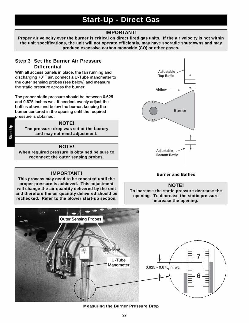
Step 3 Set the Burner Air PressureDifferential
With all access panels in place, the fan running anddischarging 70°F air, connect a U-Tube manometer tothe outer sensing probes (see below) and measurethe static pressure across the burner.
The proper static pressure should be between 0.625and 0.675 inches wc. If needed, evenly adjust thebaffles above and below the burner, keeping theburner centered in the opening until the requiredpressure is obtained.
Outer Sensing Probes
U-TubeManometer
AdjustableTop Baffle
Airflow
Burner
AdjustableBottom Baffle
IMPORTANT!Proper air velocity over the burner is critical on direct fired gas units. If the air velocity is not withinthe unit specifications, the unit will not operate efficiently, may have sporadic shutdowns and may
produce excessive carbon monoxide (CO) or other gases.
NOTE!To increase the static pressure decrease the
opening. To decrease the static pressureincrease the opening.
IMPORTANT!This process may need to be repeated until theproper pressure is achieved. This adjustment
will change the air quantity delivered by the unitand therefore the air quantity delivered should berechecked. Refer to the blower start-up section.
NOTE!When required pressure is obtained be sure to
reconnect the outer sensing probes.
NOTE!The pressure drop was set at the factory
and may not need adjustment.
Burner and Baffles
Measuring the Burner Pressure Drop
23
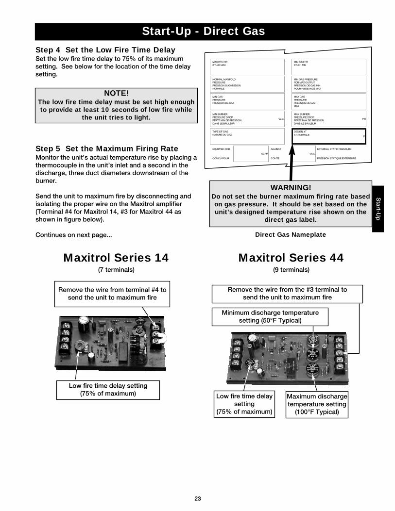
Remove the wire from terminal #4 tosend the unit to maximum fire
Start-Up - Direct GasS
tart-Up
Low fire time delay setting(75% of maximum)
Remove the wire from the #3 terminal to send the unit to maximum fire
Maximum dischargetemperature setting
(100°F Typical)
Minimum discharge temperaturesetting (50°F Typical)
Low fire time delaysetting
(75% of maximum)
Step 5 Set the Maximum Firing RateMonitor the unit’s actual temperature rise by placing athermocouple in the unit’s inlet and a second in thedischarge, three duct diameters downstream of theburner.
Send the unit to maximum fire by disconnecting andisolating the proper wire on the Maxitrol amplifier(Terminal #4 for Maxitrol 14, #3 for Maxitrol 44 asshown in figure below).
Continues on next page...
Step 4 Set the Low Fire Time DelaySet the low fire time delay to 75% of its maximumsetting. See below for the location of the time delaysetting.
WARNING!Do not set the burner maximum firing rate basedon gas pressure. It should be set based on theunit’s designed temperature rise shown on the
direct gas label.
“W.C.
F
PSI
MAX BTU/HRBTU/H MAX
NORMAL MANIFOLDPRESSUREPRESSION D’ADMISSIONNORMALE
MIN GASPRESSUREPRESSION DE GAZ
MIN BURNERPRESSURE DROPPERTE MIN DE PRESSIONDANS LE BRULEUR
TYPE OF GASNATURE DU GAZ
MIN BTU/HRBTU/H MIN
MIN GAS PRESSUREFOR MAX OUTPUTPRESSION DE GAZ MINPOUR PUISSANCE MAX
MAX BURNERPRESSURE DROPPERTE MAX DE PRESSIONDANS LE BRULEUR
MAX GASPRESSUREPRESSION DE GAZMAX
DESIGN ∆T∆T NORMALE
EQUIPPED FOR
CONCU POUR
SCFM “W.C.
EXTERNAL STATIC PRESSURE
PRESSION STATIQUE EXTERIEURE
AGAINST
CONTE
Direct Gas Nameplate
NOTE!The low fire time delay must be set high enoughto provide at least 10 seconds of low fire while
the unit tries to light.
Maxitrol Series 44(9 terminals)
Maxitrol Series 14(7 terminals)
24
Start-Up - Direct Gas
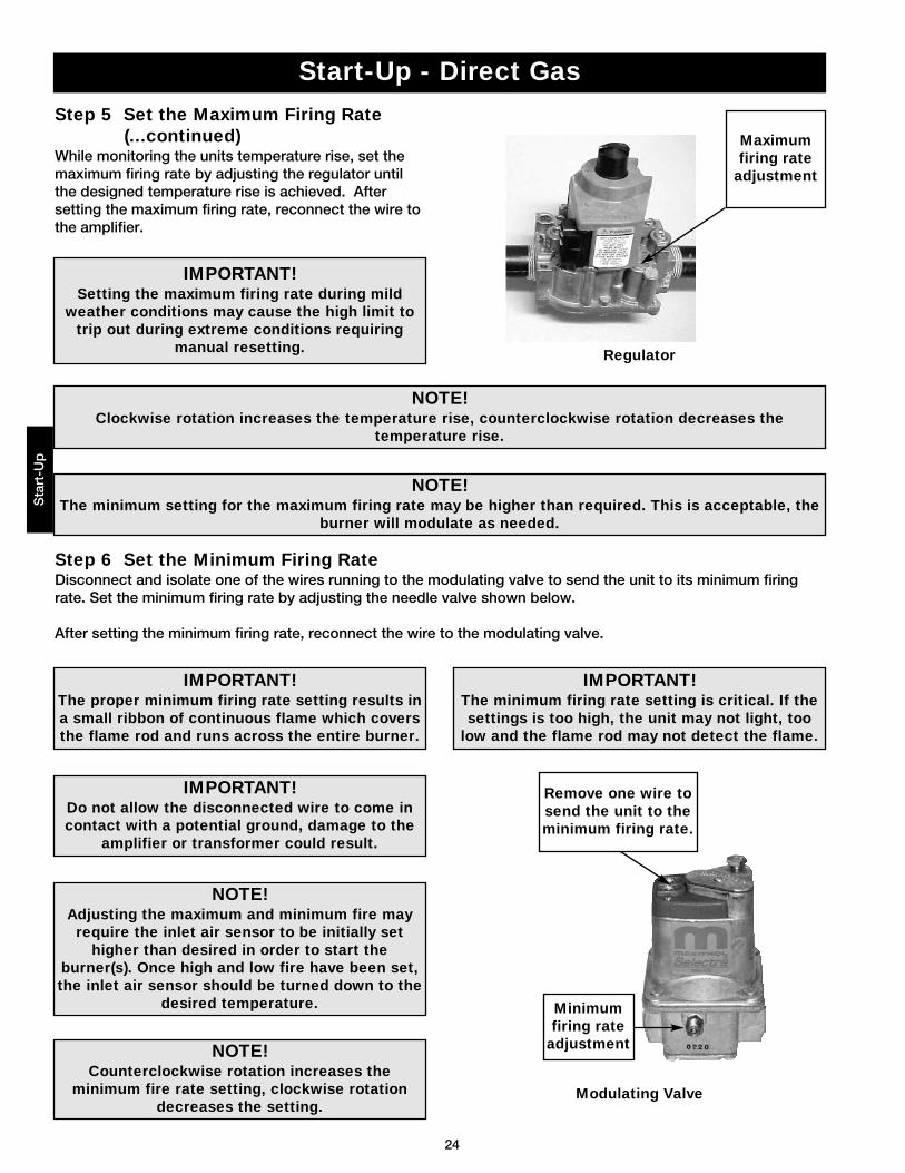
Step 6 Set the Minimum Firing RateDisconnect and isolate one of the wires running to the modulating valve to send the unit to its minimum firingrate. Set the minimum firing rate by adjusting the needle valve shown below.
After setting the minimum firing rate, reconnect the wire to the modulating valve.
Minimumfiring rate
adjustment
Remove one wire tosend the unit to theminimum firing rate.
IMPORTANT!The proper minimum firing rate setting results ina small ribbon of continuous flame which coversthe flame rod and runs across the entire burner.
IMPORTANT!The minimum firing rate setting is critical. If thesettings is too high, the unit may not light, too
low and the flame rod may not detect the flame.
IMPORTANT!Do not allow the disconnected wire to come incontact with a potential ground, damage to the
amplifier or transformer could result.
Sta
rt-U
p
NOTE!Adjusting the maximum and minimum fire mayrequire the inlet air sensor to be initially set
higher than desired in order to start theburner(s). Once high and low fire have been set,the inlet air sensor should be turned down to the
desired temperature.
NOTE!Counterclockwise rotation increases the
minimum fire rate setting, clockwise rotationdecreases the setting.
Step 5 Set the Maximum Firing Rate(...continued)
While monitoring the units temperature rise, set themaximum firing rate by adjusting the regulator untilthe designed temperature rise is achieved. Aftersetting the maximum firing rate, reconnect the wire tothe amplifier.
IMPORTANT!Setting the maximum firing rate during mild
weather conditions may cause the high limit totrip out during extreme conditions requiring
manual resetting.
NOTE!Clockwise rotation increases the temperature rise, counterclockwise rotation decreases the
temperature rise.
NOTE!The minimum setting for the maximum firing rate may be higher than required. This is acceptable, the
burner will modulate as needed.
Maximumfiring rate
adjustment
Regulator
Modulating Valve
25
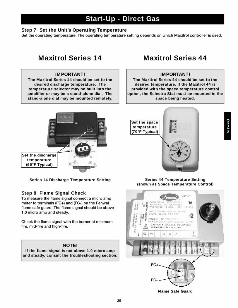
Step 8 Flame Signal Check To measure the flame signal connect a micro ampmeter to terminals (FC+) and (FC-) on the Fenwalflame safe guard. The flame signal should be above1.0 micro amp and steady.
Check the flame signal with the burner at minimumfire, mid-fire and high-fire.
NOTE!If the flame signal is not above 1.0 micro amp
and steady, consult the troubleshooting section.
Start-Up - Direct Gas
Step 7 Set the Unit’s Operating TemperatureSet the operating temperature. The operating temperature setting depends on which Maxitrol controller is used.
Maxitrol Series 14
Set the dischargetemperature (65°F Typical)
IMPORTANT!The Maxitrol Series 14 should be set to the
desired discharge temperature. Thetemperature selector may be built into theamplifier or may be a stand-alone dial. Thestand-alone dial may be mounted remotely.
Maxitrol Series 44
IMPORTANT!The Maxitrol Series 44 should be set to thedesired temperature. If the Maxitrol 44 is
provided with the space temperature controloption, the Selectra Stat must be mounted in the
space being heated.
Set the spacetemperature (70°F Typical)
Start-U
p
Series 14 Discharge Temperature Setting Series 44 Temperature Setting(shown as Space Temperature Control)
Flame Safe Guard
FC+
FC-
26
Step 6 Adjust the Water Bleed-Off RateThe water bleed-off rate is dependent on the water’s mineral content. The bleed-off should be adjusted basedon the media’s mineral deposits after two weeks of service.
Step 8 Put the Unit into ServiceRemove the jumper, and energize the blower(s). Verify proper operation.
Sta
rt-U
p
Start-Up - Evaporative Cooling Recirculating (Optional)
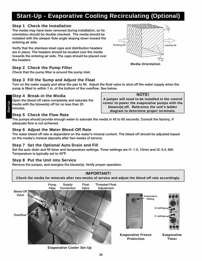
Step 1 Check the InstallationThe media may have been removed during installation, so itsorientation should be double checked. The media should beinstalled with the steeper flute angle sloping down toward theentering air side.
Verify that the stainless steel caps and distribution headersare in place. The headers should be located over the mediatowards the entering air side. The caps should be placed overthe headers.
Leaving AirEntering Air
45°
15°
Step 2 Check the Pump FilterCheck that the pump filter is around the pump inlet.
Step 3 Fill the Sump and Adjust the FloatTurn on the water supply and allow the pan to fill. Adjust the float valve to shut-off the water supply when thesump is filled to within 1 in. of the bottom of the overflow. See below.
Step 5 Check the Flow RateThe pumps should provide enough water to saturate the media in 45 to 60 seconds. Consult the factory, ifadequate flow is not achieved.
Bleed-OffValve
Overflow
PumpFilter
Threaded FloatAdjustment
SupplyConnection
FloatValve
Step 7 Set the Optional Auto Drain and FillSet the auto drain and fill timer and temperature settings. Timer settings are t1: 1.0, 10min and t2: 0.4, 60hTemperature is typically set to 45ºF.
IMPORTANT!Check the media for minerals after two weeks of service and adjust the bleed-off rate accordingly.
NOTE!A jumper will need to be installed in the controlcenter to power the evaporative pumps with the
blower(s) off. Reference the unit’s ladderdiagram to determine proper terminals.
EvaporativeTimer
t2 settings
t1 settings
Evaporative FreezeProtection
TemperatureSetting
Step 4 Break-in the MediaOpen the bleed-off valve completely and saturate themedia with the blower(s) off for no less than 20minutes.
Media Orientation
Evaporative Cooler Set-Up
27
NOTE!The minimum cooling temperature is preset to the factory recommended 75ºF. Steps 5-7 should only
be complete if the minimum cooling temperature needs adjustment.
NOTE!The inlet air sensor function overrides and shuts down the evaporative cooler if the outside
temperature falls below the minimum cooling temperature.
Step 5 Enter Program ModePress and hold the Enter Key for three
seconds. The display will read “Pro” whenProgram Mode is active.
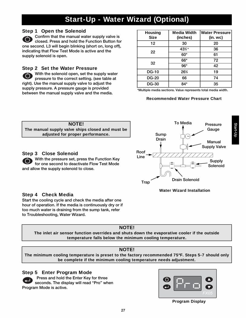
Start-Up - Water Wizard (Optional)
NOTE!The manual supply valve ships closed and must be
adjusted for proper performance.
Step 2 Set the Water PressureWith the solenoid open, set the supply waterpressure to the correct setting. (see table at
right). Use the manual supply valve to adjust thesupply pressure. A pressure gauge is providedbetween the manual supply valve and the media.
Step 3 Close SolenoidWith the pressure set, press the Function Keyfor one second to deactivate Flow Test Mode
and allow the supply solenoid to close.
Step 4 Check MediaStart the cooling cycle and check the media after onehour of operation. If the media is continuously dry or iftoo much water is draining from the sump tank, referto Troubleshooting, Water Wizard.
Step 1 Open the SolenoidConfirm that the manual water supply valve isclosed. Press and hold the Function Button for
one second. L3 will begin blinking (short on, long off),indicating that Flow Test Mode is active and thesupply solenoid is open.
Program Display
Drain Solenoid
SupplySolenoid
ManualSupply Valve
PressureGauge
To Media
SumpDrain
RoofLine
Trap
Water Wizard Installation
Start-U
p
Recommended Water Pressure Chart
HousingSize
Media Width(inches)
Water Pressure(in. wc)
12 30 20
22433⁄4 * 3660* 61
3266* 7296* 42
DG-10 263⁄4 19
DG-20 66 74
DG-30 84* 35*Multiple media sections. Value represents total media width.
28
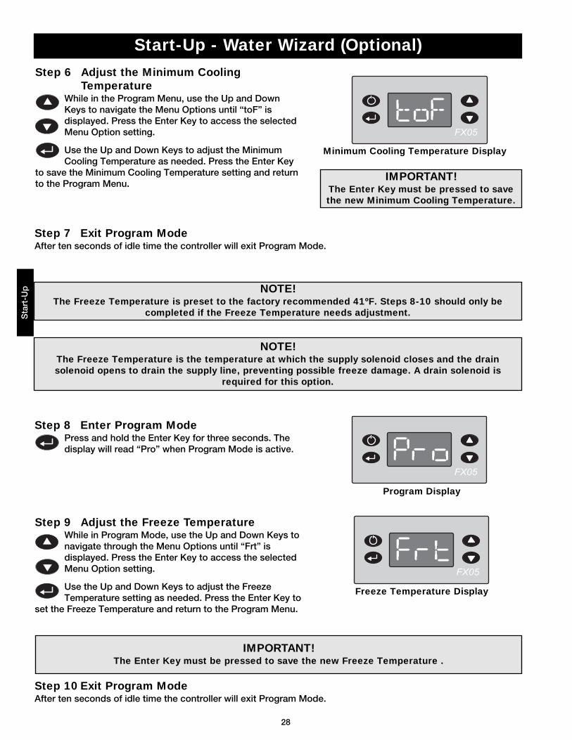
Step 8 Enter Program ModePress and hold the Enter Key for three seconds. Thedisplay will read “Pro” when Program Mode is active.
Step 9 Adjust the Freeze TemperatureWhile in Program Mode, use the Up and Down Keys tonavigate through the Menu Options until “Frt” isdisplayed. Press the Enter Key to access the selectedMenu Option setting.
Use the Up and Down Keys to adjust the FreezeTemperature setting as needed. Press the Enter Key to
set the Freeze Temperature and return to the Program Menu.
Step 10 Exit Program ModeAfter ten seconds of idle time the controller will exit Program Mode.
Step 7 Exit Program ModeAfter ten seconds of idle time the controller will exit Program Mode.
NOTE!The Freeze Temperature is the temperature at which the supply solenoid closes and the drainsolenoid opens to drain the supply line, preventing possible freeze damage. A drain solenoid is
required for this option.
NOTE!The Freeze Temperature is preset to the factory recommended 41ºF. Steps 8-10 should only be
completed if the Freeze Temperature needs adjustment.
Step 6 Adjust the Minimum CoolingTemperature
While in the Program Menu, use the Up and DownKeys to navigate the Menu Options until “toF” isdisplayed. Press the Enter Key to access the selectedMenu Option setting.
Use the Up and Down Keys to adjust the MinimumCooling Temperature as needed. Press the Enter Key
to save the Minimum Cooling Temperature setting and returnto the Program Menu.
IMPORTANT!The Enter Key must be pressed to save the new Freeze Temperature .
IMPORTANT!The Enter Key must be pressed to savethe new Minimum Cooling Temperature.
Start-Up - Water Wizard (Optional)
Minimum Cooling Temperature Display
Program Display
Freeze Temperature Display
Sta
rt-U
p
29
Operation - VAV / Recirculating UnitsO
peratio
n
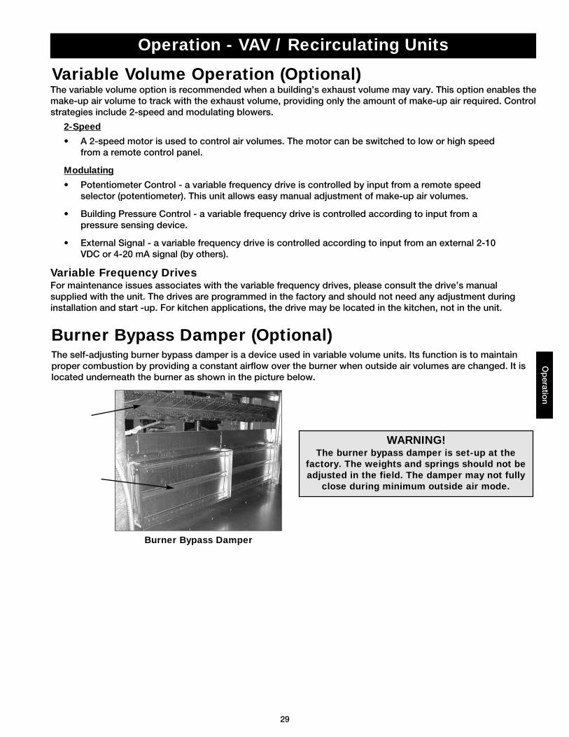
The self-adjusting burner bypass damper is a device used in variable volume units. Its function is to maintainproper combustion by providing a constant airflow over the burner when outside air volumes are changed. It islocated underneath the burner as shown in the picture below.
Variable Volume Operation (Optional)
WARNING!The burner bypass damper is set-up at the
factory. The weights and springs should not beadjusted in the field. The damper may not fully
close during minimum outside air mode.
The variable volume option is recommended when a building’s exhaust volume may vary. This option enables themake-up air volume to track with the exhaust volume, providing only the amount of make-up air required. Controlstrategies include 2-speed and modulating blowers.
2-Speed
• A 2-speed motor is used to control air volumes. The motor can be switched to low or high speedfrom a remote control panel.
Modulating
• Potentiometer Control - a variable frequency drive is controlled by input from a remote speedselector (potentiometer). This unit allows easy manual adjustment of make-up air volumes.
• Building Pressure Control - a variable frequency drive is controlled according to input from apressure sensing device.
• External Signal - a variable frequency drive is controlled according to input from an external 2-10VDC or 4-20 mA signal (by others).
Variable Frequency DrivesFor maintenance issues associates with the variable frequency drives, please consult the drive’s manualsupplied with the unit. The drives are programmed in the factory and should not need any adjustment duringinstallation and start -up. For kitchen applications, the drive may be located in the kitchen, not in the unit.
Burner Bypass Damper (Optional)
Burner Bypass Damper
30
Op
erat
ion
Operation - VAV / Recirculating Units
Recirculation Operation (Optional)The recirculation operation option is recommended when the ventilation equipment provides the primary sourceof heating for the space. A minimum of 20% outdoor air is mixed with up to 80% filtered recirculated air. Controlstrategies include 2-position and modulating dampers.
2-Position Damper
• A 2-position spring return actuator is used to control the return air amounts. The damper movesfrom open to closed. If power is cut to the unit, the outdoor air damper will fail close.
Modulating
• Potentiometer Control - a modulating spring return actuator is used to control the return airamounts. The return air damper modulates from fully open to fully closed based on a signal from aremote potentiometer.
• Building Pressure Control - a modulating spring return actuator is used to control the return airamounts. The return air damper modulates from fully open to fully closed based on a signal from aremote pressure sensing device.
• External Signal - a modulating spring return actuator is used to control the return air amounts.Return air damper modulates from fully open to fully closed based on an external 2-10 VDC or 4-20mA signal (by others).
31
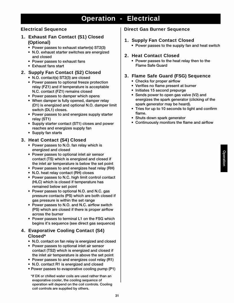
Operation - Electrical
1. Exhaust Fan Contact (S1) Closed(Optional)• Power passes to exhaust starter(s) ST2(3)• N.O. exhaust starter switches are energized
and closed• Power passes to exhaust fans• Exhaust fans start
2. Supply Fan Contact (S2) Closed• N.O. contact(s) ST2(3) are closed• Power passes to optional freeze protection
relay (FZ1) and if temperature is acceptableN.C. contact (FZ1) remains closed
• Power passes to damper which opens• When damper is fully opened, damper relay
(D1) is energized and optional N.O. damper limitswitch (DL1) closes.
• Power passes to and energizes supply starterrelay (ST1)
• Supply starter contact (ST1) closes and powerreaches and energizes supply fan
• Supply fan starts
4. Evaporative Cooling Contact (S4)Closed*• N.O. contact on fan relay is energized and closed• Power passes to optional inlet air sensor
contact (TS2) which is energized and closed ifthe inlet air temperature is above the set point
• Power passes to and energizes cool relay (R1)• N.O. contact R1 is energized and closed • Power passes to evaporative cooling pump (P1)
*If DX or chilled water coils are used rather than anevaporative cooler, the cooling sequence ofoperation will depend on the coil controls. Coolingcoil controls are supplied by others.
3. Heat Contact (S4) Closed• Power passes to N.O. fan relay which is
energized and closed• Power passes to optional inlet air sensor
contact (TS) which is energized and closed ifthe inlet air temperature is below the set point
• Power passes to and energizes heat relay (RH)• N.O. heat relay contact (RH) closes• Power passes to N.C. high limit control contact
(HLC) which is closed if temperature hasremained below set point
• Power passes to optional N.O. and N.C. gaspressure contacts (PS) which are both closed ifgas pressure is within the set range
• Power passes to N.O. and N.C. airflow switch(PS) which are closed if there is proper airflowacross the burner
• Power passes to terminal L1 on the FSG whichbegins it’s sequence (see direct gas sequence)
1. Supply Fan Contact Closed• Power passes to the supply fan and heat switch
2. Heat Contact Closed• Power passes to the heat relay then to the
Flame Safe Guard
3. Flame Safe Guard (FSG) Sequence• Checks for proper airflow• Verifies no flame present at burner• Initiates 15 second prepurge• Sends power to open gas valve (V2) and
energizes the spark generator (clicking of thespark generator may be heard).
• Tries for up to 10 seconds to light and confirmflame.
• Shuts down spark generator• Continuously monitors the flame and airflow
Electrical Sequence Direct Gas Burner Sequence
Op
eration
32
Op
eration
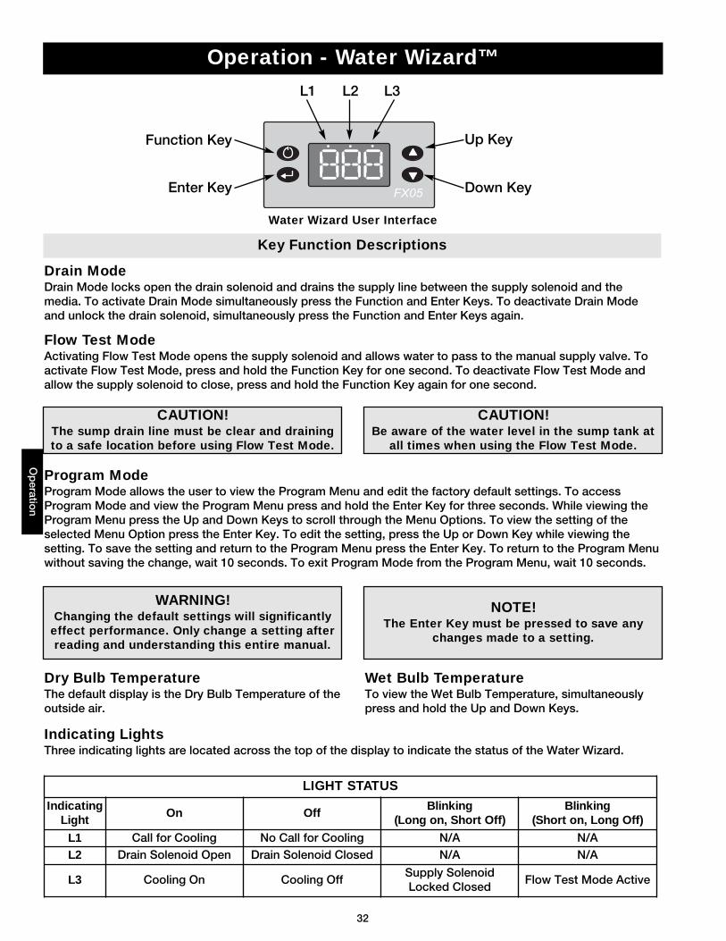
Operation - Water Wizard™
Function Key
L1 L2 L3
Enter Key
Up Key
Down Key
Flow Test ModeActivating Flow Test Mode opens the supply solenoid and allows water to pass to the manual supply valve. Toactivate Flow Test Mode, press and hold the Function Key for one second. To deactivate Flow Test Mode andallow the supply solenoid to close, press and hold the Function Key again for one second.
Program ModeProgram Mode allows the user to view the Program Menu and edit the factory default settings. To accessProgram Mode and view the Program Menu press and hold the Enter Key for three seconds. While viewing theProgram Menu press the Up and Down Keys to scroll through the Menu Options. To view the setting of theselected Menu Option press the Enter Key. To edit the setting, press the Up or Down Key while viewing thesetting. To save the setting and return to the Program Menu press the Enter Key. To return to the Program Menuwithout saving the change, wait 10 seconds. To exit Program Mode from the Program Menu, wait 10 seconds.
Drain ModeDrain Mode locks open the drain solenoid and drains the supply line between the supply solenoid and themedia. To activate Drain Mode simultaneously press the Function and Enter Keys. To deactivate Drain Modeand unlock the drain solenoid, simultaneously press the Function and Enter Keys again.
Dry Bulb TemperatureThe default display is the Dry Bulb Temperature of theoutside air.
Wet Bulb TemperatureTo view the Wet Bulb Temperature, simultaneouslypress and hold the Up and Down Keys.
CAUTION!The sump drain line must be clear and drainingto a safe location before using Flow Test Mode.
NOTE!The Enter Key must be pressed to save any
changes made to a setting.
WARNING!Changing the default settings will significantlyeffect performance. Only change a setting afterreading and understanding this entire manual.
CAUTION!Be aware of the water level in the sump tank at
all times when using the Flow Test Mode.
Indicating LightsThree indicating lights are located across the top of the display to indicate the status of the Water Wizard.
Water Wizard User Interface
Key Function Descriptions
LIGHT STATUS
IndicatingLight
On OffBlinking
(Long on, Short Off)Blinking
(Short on, Long Off)
L1 Call for Cooling No Call for Cooling N/A N/AL2 Drain Solenoid Open Drain Solenoid Closed N/A N/A
L3 Cooling On Cooling OffSupply SolenoidLocked Closed
Flow Test Mode Active
33
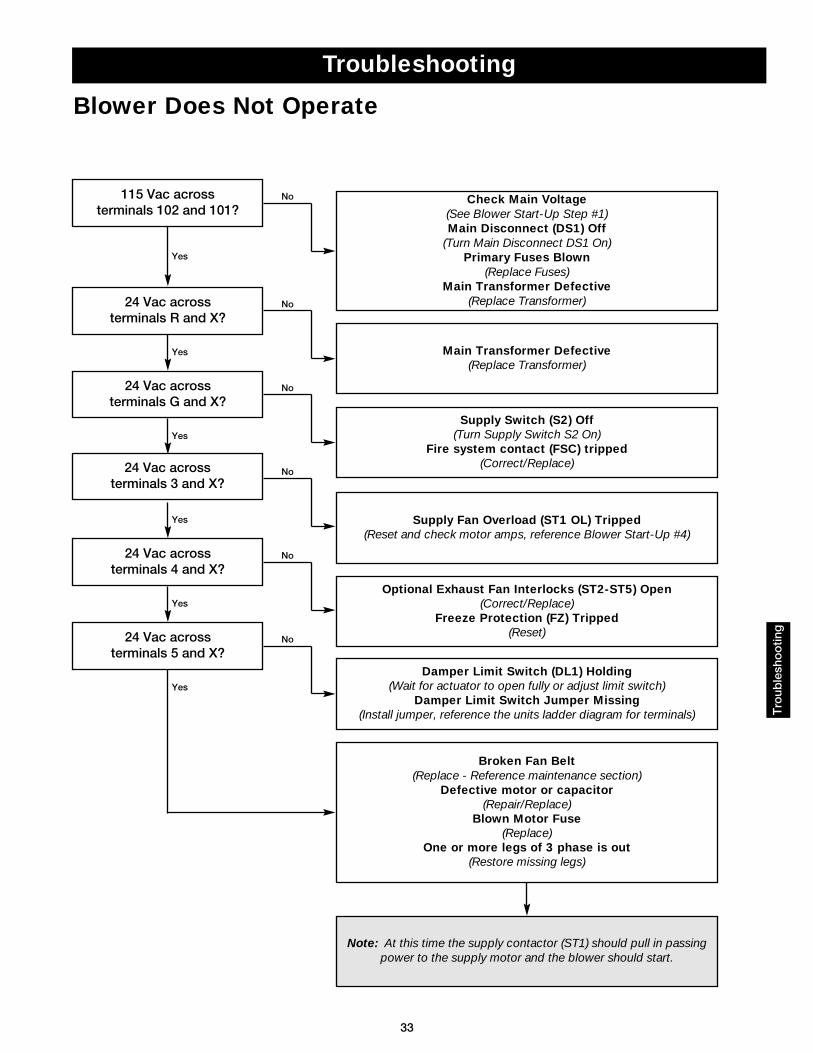
Troubleshooting
115 Vac across terminals 102 and 101?
Check Main Voltage(See Blower Start-Up Step #1)Main Disconnect (DS1) Off
(Turn Main Disconnect DS1 On)Primary Fuses Blown
(Replace Fuses)Main Transformer Defective
(Replace Transformer)24 Vac across terminals R and X?
Main Transformer Defective(Replace Transformer)
24 Vac acrossterminals 5 and X?
24 Vac acrossterminals 4 and X?
24 Vac acrossterminals G and X?
Supply Switch (S2) Off(Turn Supply Switch S2 On)
Fire system contact (FSC) tripped(Correct/Replace)
No
No
No
No
No
No
Yes
Yes
Yes
Yes
Yes
Note: At this time the supply contactor (ST1) should pull in passingpower to the supply motor and the blower should start.
Yes
Blower Does Not Operate
Broken Fan Belt(Replace - Reference maintenance section)
Defective motor or capacitor(Repair/Replace)
Blown Motor Fuse(Replace)
One or more legs of 3 phase is out(Restore missing legs)
Tro
uble
sho
otin
g
24 Vac acrossterminals 3 and X?
Supply Fan Overload (ST1 OL) Tripped(Reset and check motor amps, reference Blower Start-Up #4)
Damper Limit Switch (DL1) Holding(Wait for actuator to open fully or adjust limit switch)
Damper Limit Switch Jumper Missing(Install jumper, reference the units ladder diagram for terminals)
Optional Exhaust Fan Interlocks (ST2-ST5) Open(Correct/Replace)
Freeze Protection (FZ) Tripped(Reset)
34
Tro
uble
sho
otin
g
Troubleshooting
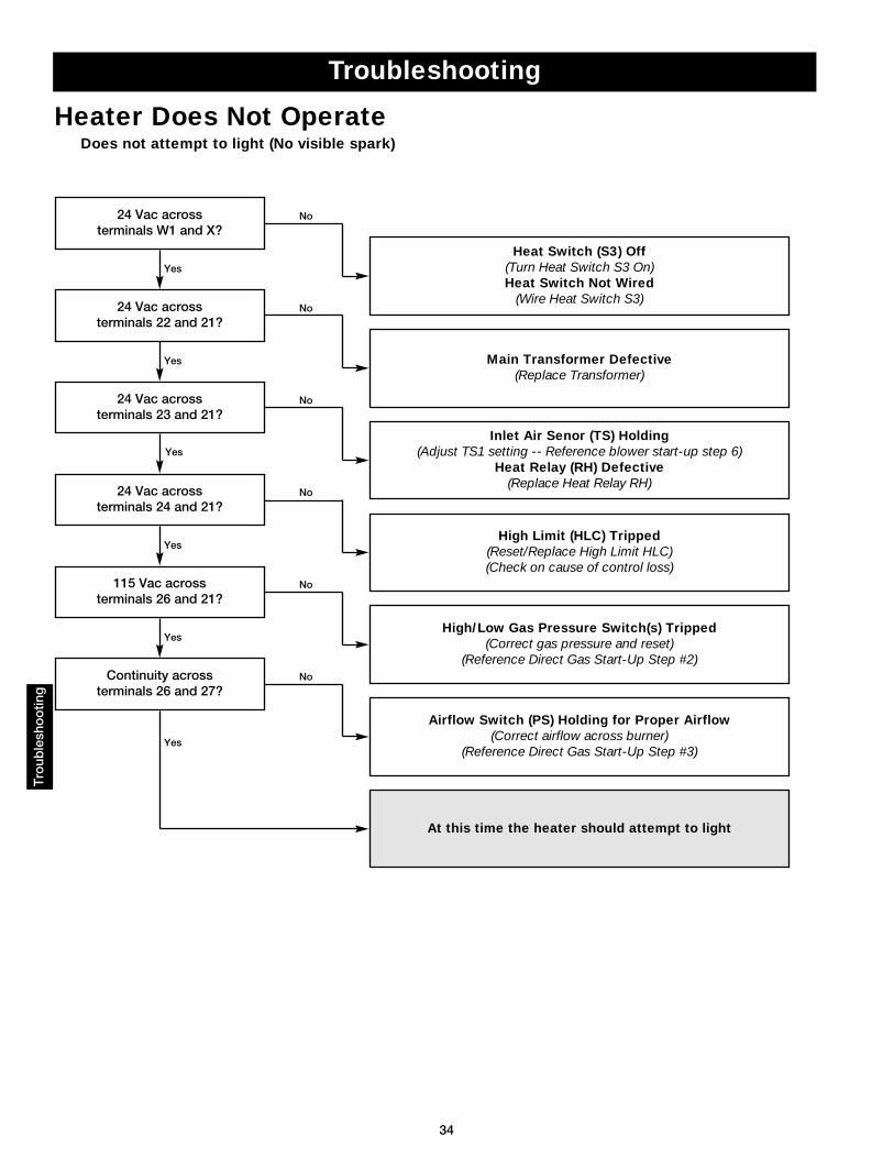
24 Vac across terminals W1 and X?
Heat Switch (S3) Off (Turn Heat Switch S3 On)Heat Switch Not Wired
(Wire Heat Switch S3)24 Vac across
terminals 22 and 21?
Main Transformer Defective(Replace Transformer)
115 Vac across terminals 26 and 21?
High/Low Gas Pressure Switch(s) Tripped(Correct gas pressure and reset)
(Reference Direct Gas Start-Up Step #2)
24 Vac across terminals 24 and 21?
High Limit (HLC) Tripped(Reset/Replace High Limit HLC)(Check on cause of control loss)
Continuity across terminals 26 and 27?
24 Vac across terminals 23 and 21?
Inlet Air Senor (TS) Holding(Adjust TS1 setting -- Reference blower start-up step 6)
Heat Relay (RH) Defective(Replace Heat Relay RH)
No
No
No
No
No
No
Yes
Yes
Yes
Yes
Yes
Airflow Switch (PS) Holding for Proper Airflow(Correct airflow across burner)
(Reference Direct Gas Start-Up Step #3)
Yes
At this time the heater should attempt to light
Heater Does Not OperateDoes not attempt to light (No visible spark)
35
Troubleshooting
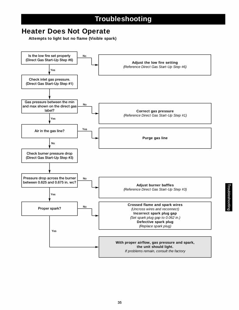
Check inlet gas pressure.(Direct Gas Start-Up Step #1)
Is the low fire set properly(Direct Gas Start-Up Step #6)
Gas pressure between the minand max shown on the direct gas
label? Correct gas pressure(Reference Direct Gas Start-Up Step #1)
Proper spark?Crossed flame and spark wires
(Uncross wires and reconnect)Incorrect spark plug gap
(Set spark plug gap to 0.062 in.)Defective spark plug
(Replace spark plug)
Pressure drop across the burnerbetween 0.625 and 0.675 in. wc?
Adjust burner baffles(Reference Direct Gas Start-Up Step #3)
Check burner pressure drop(Direct Gas Start-Up Step #3)
Air in the gas line?
Purge gas line
No
Yes
No
No
Yes
Yes
No
Heater Does Not OperateAttempts to light but no flame (Visible spark)
Yes
With proper airflow, gas pressure and spark, the unit should light.
If problems remain, consult the factory
Adjust the low fire setting(Reference Direct Gas Start-Up Step #6)
No
Yes
Tro
ublesho
oting
36
Tro
uble
sho
otin
g
Troubleshooting
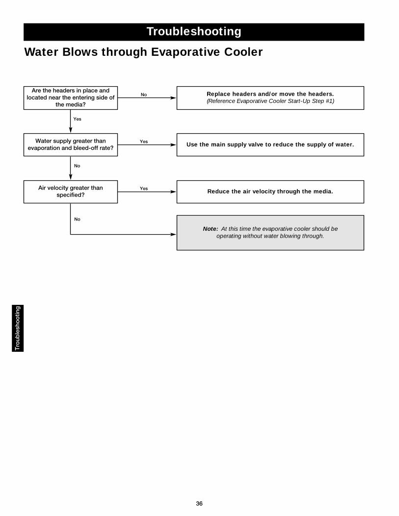
Water Blows through Evaporative Cooler
Water supply greater thanevaporation and bleed-off rate?
Use the main supply valve to reduce the supply of water.
Air velocity greater thanspecified?
Reduce the air velocity through the media.
Are the headers in place andlocated near the entering side of
the media?
Replace headers and/or move the headers.(Reference Evaporative Cooler Start-Up Step #1)
Yes
No
Yes
Yes
No
No
Note: At this time the evaporative cooler should be operating without water blowing through.
37
Troubleshooting
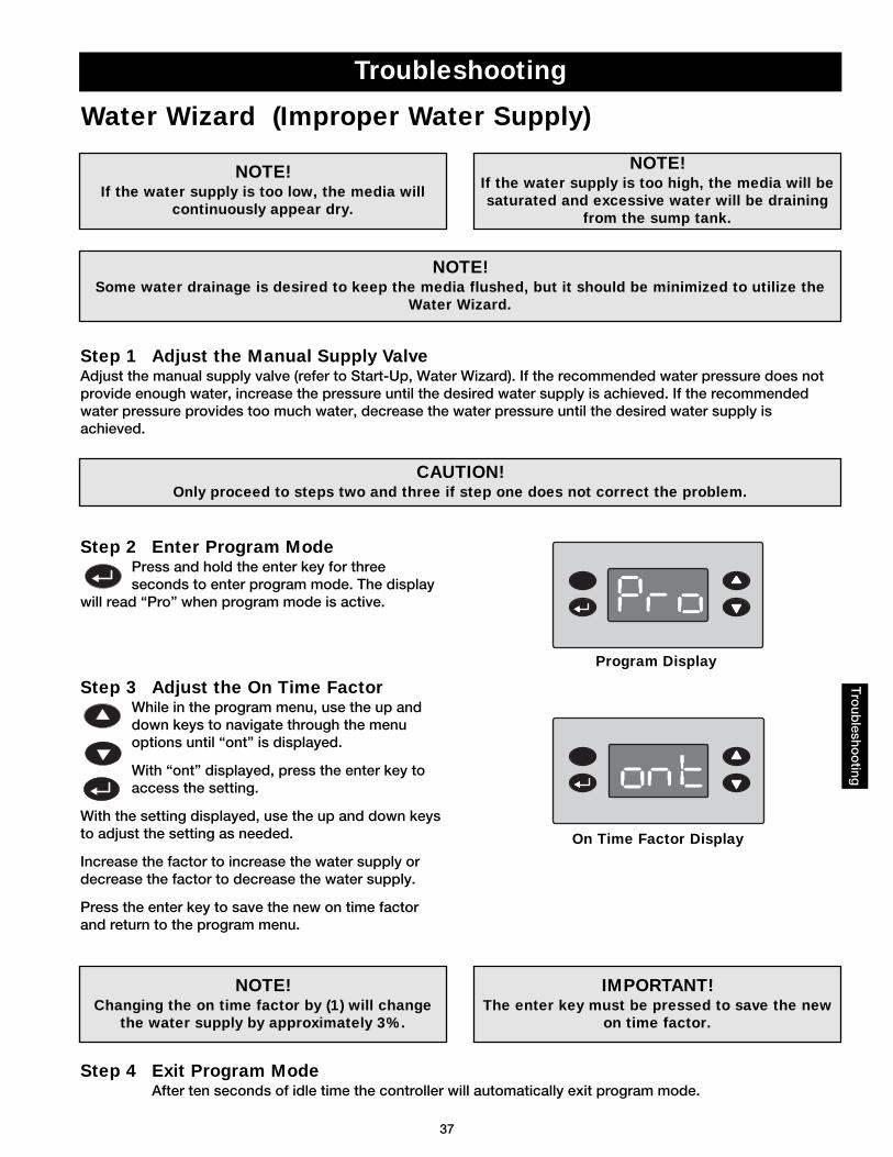
Water Wizard (Improper Water Supply)
Tro
ublesho
oting
CAUTION!Only proceed to steps two and three if step one does not correct the problem.
Step 2 Enter Program ModePress and hold the enter key for threeseconds to enter program mode. The display
will read “Pro” when program mode is active.
Step 1 Adjust the Manual Supply ValveAdjust the manual supply valve (refer to Start-Up, Water Wizard). If the recommended water pressure does notprovide enough water, increase the pressure until the desired water supply is achieved. If the recommendedwater pressure provides too much water, decrease the water pressure until the desired water supply isachieved.
Step 3 Adjust the On Time FactorWhile in the program menu, use the up anddown keys to navigate through the menuoptions until “ont” is displayed.
With “ont” displayed, press the enter key toaccess the setting.
With the setting displayed, use the up and down keysto adjust the setting as needed.
Increase the factor to increase the water supply ordecrease the factor to decrease the water supply.
Press the enter key to save the new on time factorand return to the program menu.
Step 4 Exit Program ModeAfter ten seconds of idle time the controller will automatically exit program mode.
NOTE!If the water supply is too low, the media will
continuously appear dry.
NOTE!Changing the on time factor by (1) will change
the water supply by approximately 3%.
NOTE!If the water supply is too high, the media will besaturated and excessive water will be draining
from the sump tank.
NOTE!Some water drainage is desired to keep the media flushed, but it should be minimized to utilize the
Water Wizard.
IMPORTANT!The enter key must be pressed to save the new
on time factor.
Program Display
On Time Factor Display
38
Tro
uble
sho
otin
g
Troubleshooting
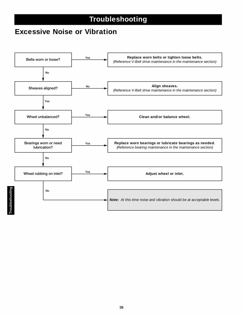
Excessive Noise or Vibration
Note: At this time noise and vibration should be at acceptable levels.
Sheaves aligned?Align sheaves.
(Reference V-Belt drive maintenance in the maintenance section)
Wheel unbalanced? Clean and/or balance wheel.
Belts worn or loose?Replace worn belts or tighten loose belts.
(Reference V-Belt drive maintenance in the maintenance section)
Yes
Yes
No
No
Yes
Bearings worn or needlubrication?
Replace worn bearings or lubricate bearings as needed.(Reference bearing maintenance in the maintenance section)
Yes
No
Wheel rubbing on inlet? Adjust wheel or inlet.Yes
No
No
39
Maintenance - Routine
CAUTION!Lock-out the gas and the electrical power to the unit before performing any maintenance or service
operations to this unit.
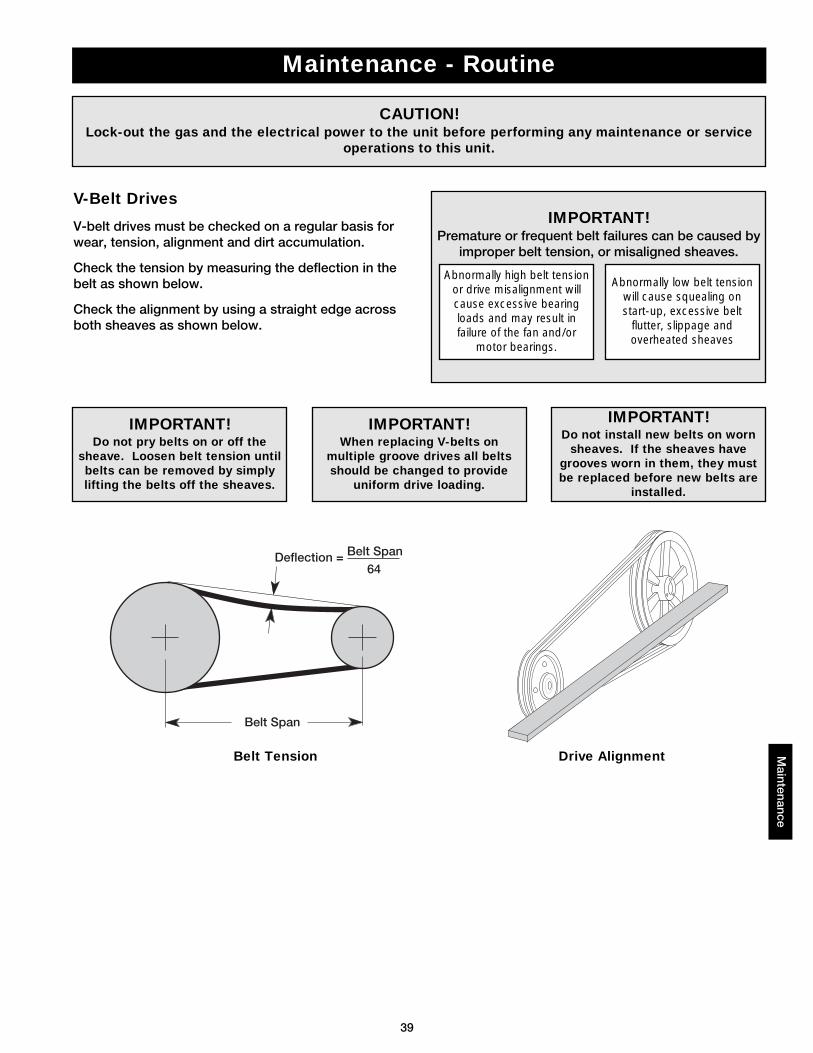
IMPORTANT!Do not install new belts on worn
sheaves. If the sheaves havegrooves worn in them, they mustbe replaced before new belts are
installed.
IMPORTANT!Premature or frequent belt failures can be caused by
improper belt tension, or misaligned sheaves.
Abnormally low belt tensionwill cause squealing onstart-up, excessive belt
flutter, slippage andoverheated sheaves
Abnormally high belt tensionor drive misalignment willcause excessive bearingloads and may result infailure of the fan and/or
motor bearings.
IMPORTANT!When replacing V-belts on
multiple groove drives all beltsshould be changed to provide
uniform drive loading.
Belt Span
Deflection = Belt Span64
IMPORTANT!Do not pry belts on or off the
sheave. Loosen belt tension untilbelts can be removed by simplylifting the belts off the sheaves.
V-Belt Drives
V-belt drives must be checked on a regular basis forwear, tension, alignment and dirt accumulation.
Check the tension by measuring the deflection in thebelt as shown below.
Check the alignment by using a straight edge acrossboth sheaves as shown below.
Maintenance
Belt Tension Drive Alignment
40
Mai
nten
ance
Maintenance - Routine
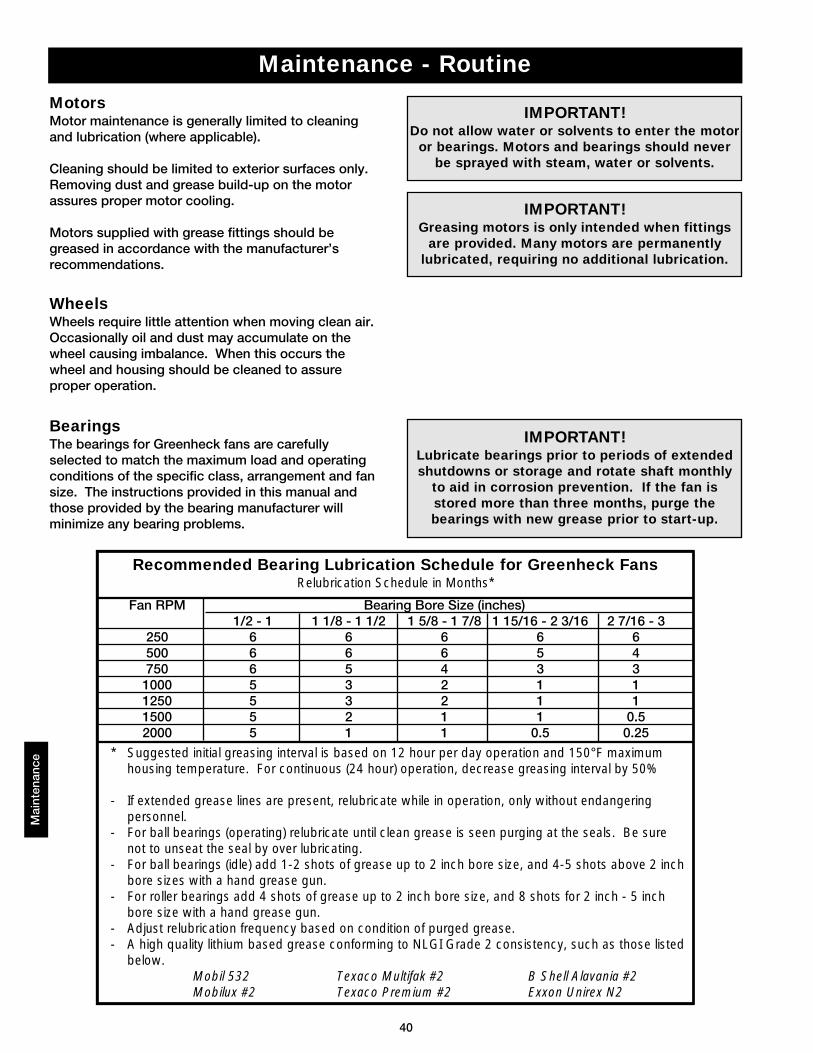
Recommended Bearing Lubrication Schedule for Greenheck FansRelubrication Schedule in Months*
BearingsThe bearings for Greenheck fans are carefullyselected to match the maximum load and operatingconditions of the specific class, arrangement and fansize. The instructions provided in this manual andthose provided by the bearing manufacturer willminimize any bearing problems.
Fan RPM Bearing Bore Size (inches)1/2 - 1 1 1/8 - 1 1/2 1 5/8 - 1 7/8 1 15/16 - 2 3/16 2 7/16 - 3
250 6 6 6 6 6500 6 6 6 5 4750 6 5 4 3 31000 5 3 2 1 11250 5 3 2 1 11500 5 2 1 1 0.52000 5 1 1 0.5 0.25
* Suggested initial greasing interval is based on 12 hour per day operation and 150°F maximum housing temperature. For continuous (24 hour) operation, decrease greasing interval by 50%
- If extended grease lines are present, relubricate while in operation, only without endangering personnel.
- For ball bearings (operating) relubricate until clean grease is seen purging at the seals. Be sure not to unseat the seal by over lubricating.
- For ball bearings (idle) add 1-2 shots of grease up to 2 inch bore size, and 4-5 shots above 2 inchbore sizes with a hand grease gun.
- For roller bearings add 4 shots of grease up to 2 inch bore size, and 8 shots for 2 inch - 5 inch bore size with a hand grease gun.
- Adjust relubrication frequency based on condition of purged grease.- A high quality lithium based grease conforming to NLGI Grade 2 consistency, such as those listed
below.Mobil 532 Texaco Multifak #2 B Shell Alavania #2Mobilux #2 Texaco Premium #2 Exxon Unirex N2
IMPORTANT!Lubricate bearings prior to periods of extendedshutdowns or storage and rotate shaft monthly
to aid in corrosion prevention. If the fan isstored more than three months, purge thebearings with new grease prior to start-up.
MotorsMotor maintenance is generally limited to cleaningand lubrication (where applicable).
Cleaning should be limited to exterior surfaces only.Removing dust and grease build-up on the motorassures proper motor cooling.
Motors supplied with grease fittings should begreased in accordance with the manufacturer’srecommendations.
IMPORTANT!Do not allow water or solvents to enter the motor
or bearings. Motors and bearings should neverbe sprayed with steam, water or solvents.
IMPORTANT!Greasing motors is only intended when fittings
are provided. Many motors are permanentlylubricated, requiring no additional lubrication.
WheelsWheels require little attention when moving clean air.Occasionally oil and dust may accumulate on thewheel causing imbalance. When this occurs thewheel and housing should be cleaned to assureproper operation.
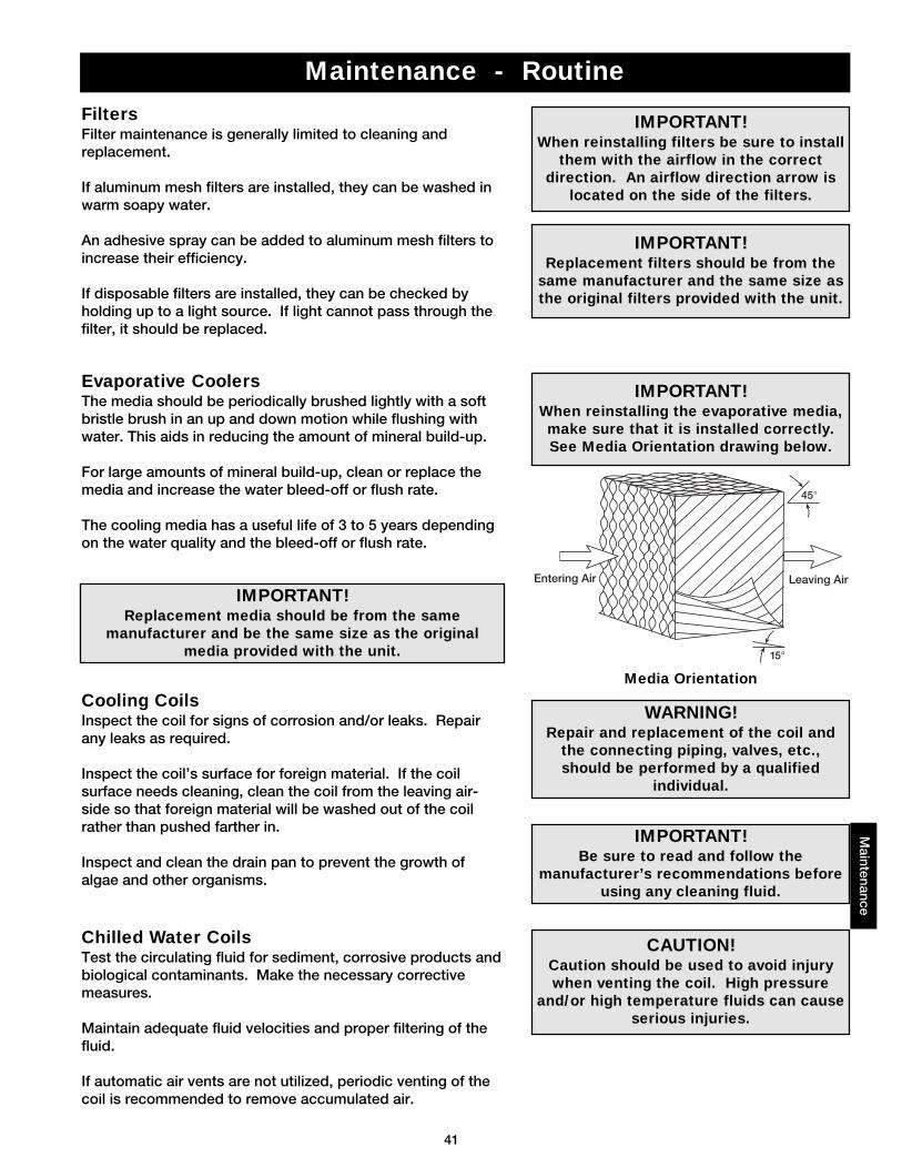
41
Maintenance - Routine
FiltersFilter maintenance is generally limited to cleaning andreplacement.
If aluminum mesh filters are installed, they can be washed inwarm soapy water.
An adhesive spray can be added to aluminum mesh filters toincrease their efficiency.
If disposable filters are installed, they can be checked byholding up to a light source. If light cannot pass through thefilter, it should be replaced.
IMPORTANT!When reinstalling filters be sure to install
them with the airflow in the correctdirection. An airflow direction arrow is
located on the side of the filters.
IMPORTANT!Replacement filters should be from the
same manufacturer and the same size asthe original filters provided with the unit.
Evaporative CoolersThe media should be periodically brushed lightly with a softbristle brush in an up and down motion while flushing withwater. This aids in reducing the amount of mineral build-up.
For large amounts of mineral build-up, clean or replace themedia and increase the water bleed-off or flush rate.
The cooling media has a useful life of 3 to 5 years dependingon the water quality and the bleed-off or flush rate.
Leaving AirEntering Air
45°
15°
IMPORTANT!Replacement media should be from the same
manufacturer and be the same size as the originalmedia provided with the unit.
IMPORTANT!When reinstalling the evaporative media,make sure that it is installed correctly.See Media Orientation drawing below.
Cooling CoilsInspect the coil for signs of corrosion and/or leaks. Repairany leaks as required.
Inspect the coil’s surface for foreign material. If the coilsurface needs cleaning, clean the coil from the leaving air-side so that foreign material will be washed out of the coilrather than pushed farther in.
Inspect and clean the drain pan to prevent the growth ofalgae and other organisms.
IMPORTANT!Be sure to read and follow the
manufacturer’s recommendations beforeusing any cleaning fluid.
WARNING!Repair and replacement of the coil and
the connecting piping, valves, etc.,should be performed by a qualified
individual.
Chilled Water CoilsTest the circulating fluid for sediment, corrosive products andbiological contaminants. Make the necessary correctivemeasures.
Maintain adequate fluid velocities and proper filtering of thefluid.
If automatic air vents are not utilized, periodic venting of thecoil is recommended to remove accumulated air.
CAUTION!Caution should be used to avoid injurywhen venting the coil. High pressure
and/or high temperature fluids can causeserious injuries.
Media Orientation
Maintenance
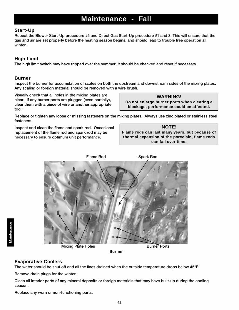
42
Mai
nten
ance
Maintenance - Fall
Start-UpRepeat the Blower Start-Up procedure #5 and Direct Gas Start-Up procedure #1 and 3. This will ensure that thegas and air are set properly before the heating season begins, and should lead to trouble free operation allwinter.
High LimitThe high limit switch may have tripped over the summer, it should be checked and reset if necessary.
BurnerInspect the burner for accumulation of scales on both the upstream and downstream sides of the mixing plates.Any scaling or foreign material should be removed with a wire brush.
Visually check that all holes in the mixing plates areclear. If any burner ports are plugged (even partially),clear them with a piece of wire or another appropriatetool.
Replace or tighten any loose or missing fasteners on the mixing plates. Always use zinc plated or stainless steelfasteners.
Inspect and clean the flame and spark rod. Occasionalreplacement of the flame rod and spark rod may benecessary to ensure optimum unit performance.
Evaporative CoolersThe water should be shut off and all the lines drained when the outside temperature drops below 45°F.
Remove drain plugs for the winter.
Clean all interior parts of any mineral deposits or foreign materials that may have built-up during the coolingseason.
Replace any worn or non-functioning parts.
WARNING!Do not enlarge burner ports when clearing a
blockage, performance could be affected.
NOTE!Flame rods can last many years, but because ofthermal expansion of the porcelain, flame rods
can fail over time.
Burner
Flame Rod
Mixing Plate Holes Burner Ports
Spark Rod
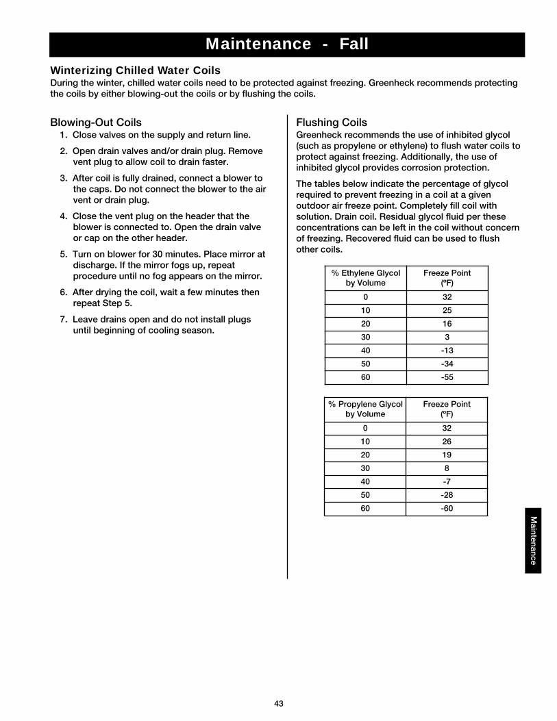
43
Maintenance - Fall
Winterizing Chilled Water CoilsDuring the winter, chilled water coils need to be protected against freezing. Greenheck recommends protectingthe coils by either blowing-out the coils or by flushing the coils.
Maintenance
% Ethylene Glycolby Volume
Freeze Point(ºF)
0 32
10 25
20 16
30 3
40 -13
50 -34
60 -55
% Propylene Glycolby Volume
Freeze Point(ºF)
0 32
10 26
20 19
30 8
40 -7
50 -28
60 -60
Blowing-Out Coils1. Close valves on the supply and return line.
2. Open drain valves and/or drain plug. Removevent plug to allow coil to drain faster.
3. After coil is fully drained, connect a blower tothe caps. Do not connect the blower to the airvent or drain plug.
4. Close the vent plug on the header that theblower is connected to. Open the drain valveor cap on the other header.
5. Turn on blower for 30 minutes. Place mirror atdischarge. If the mirror fogs up, repeatprocedure until no fog appears on the mirror.
6. After drying the coil, wait a few minutes thenrepeat Step 5.
7. Leave drains open and do not install plugsuntil beginning of cooling season.
Flushing CoilsGreenheck recommends the use of inhibited glycol(such as propylene or ethylene) to flush water coils toprotect against freezing. Additionally, the use ofinhibited glycol provides corrosion protection.
The tables below indicate the percentage of glycolrequired to prevent freezing in a coil at a givenoutdoor air freeze point. Completely fill coil withsolution. Drain coil. Residual glycol fluid per theseconcentrations can be left in the coil without concernof freezing. Recovered fluid can be used to flushother coils.
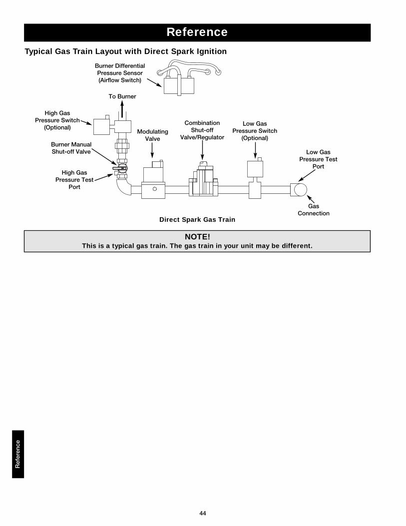
44
Ref
eren
ce
Reference
Typical Gas Train Layout with Direct Spark Ignition
Burner DifferentialPressure Sensor(Airflow Switch)
Burner ManualShut-off Valve
High GasPressure Test
Port
High GasPressure Switch
(Optional)Modulating
Valve
To Burner
CombinationShut-off
Valve/Regulator
Low GasPressure Test
Port
Low GasPressure Switch
(Optional)
GasConnection
NOTE!This is a typical gas train. The gas train in your unit may be different.
Direct Spark Gas Train
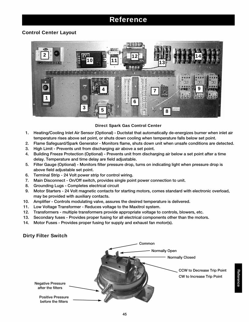
45
Reference
Control Center Layout
1. Heating/Cooling Inlet Air Sensor (Optional) - Ductstat that automatically de-energizes burner when inlet air temperature rises above set point, or shuts down cooling when temperature falls below set point.
2. Flame Safeguard/Spark Generator - Monitors flame, shuts down unit when unsafe conditions are detected.3. High Limit - Prevents unit from discharging air above a set point.4. Building Freeze Protection (Optional) - Prevents unit from discharging air below a set point after a time
delay. Temperature and time delay are field adjustable.5. Filter Gauge (Optional) - Monitors filter pressure drop, turns on indicating light when pressure drop is
above field adjustable set point.6. Terminal Strip - 24 Volt power strip for control wiring.7. Main Disconnect - On/Off switch, provides single point power connection to unit.8. Grounding Lugs - Completes electrical circuit9. Motor Starters - 24 Volt magnetic contacts for starting motors, comes standard with electronic overload,
may be provided with auxiliary contacts. 10. Amplifier - Controls modulating valve, assures the desired temperature is delivered.11. Low Voltage Transformer - Reduces voltage to the Maxitrol system.12. Transformers - multiple transformers provide appropriate voltage to controls, blowers, etc.13. Secondary fuses - Provides proper fusing for all electrical components other than the motors.14. Motor Fuses - Provides proper fusing for supply and exhaust fan motor(s).
Direct Spark Gas Control Center
1
210
3
4
6
1112
5
Reference
Dirty Filter Switch
1314
97
8
Negative Pressureafter the filters
Common
Normally Open
Normally Closed
CCW to Decrease Trip Point
CW to Increase Trip Point
Positive Pressurebefore the filters
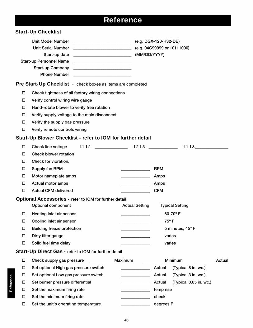
46
Ref
eren
ce
Unit Model Number ____________________________ (e.g. DGX-120-H32-DB)
Unit Serial Number ____________________________ (e.g. 04C99999 or 10111000)
Start-up date ____________________________ (MM/DD/YYYY)
Start-up Personnel Name ____________________________
Start-up Company ____________________________
Phone Number ____________________________
Pre Start-Up Checklist - check boxes as items are completed
Check tightness of all factory wiring connections
Verify control wiring wire gauge
Hand-rotate blower to verify free rotation
Verify supply voltage to the main disconnect
Verify the supply gas pressure
Verify remote controls wiring
Start-Up Blower Checklist - refer to IOM for further detail
Check line voltage L1-L2 ________________ L2-L3 ______________ L1-L3 ________________
Check blower rotation
Check for vibration.
Supply fan RPM ______________ RPM
Motor nameplate amps ______________ Amps
Actual motor amps ______________ Amps
Actual CFM delivered ______________ CFM
Optional Accessories - refer to IOM for further detail
Optional component Actual Setting Typical Setting
Heating inlet air sensor ______________ 60-70º F
Cooling inlet air sensor ______________ 75º F
Building freeze protection ______________ 5 minutes; 45º F
Dirty filter gauge ______________ varies
Solid fuel time delay ______________ varies
Start-Up Direct Gas - refer to IOM for further detail
Check supply gas pressure ____________Maximum __________ Minimum __________Actual
Set optional High gas pressure switch ______________ Actual (Typical 8 in. wc.)
Set optional Low gas pressure switch ______________ Actual (Typical 3 in. wc.)
Set burner pressure differential ______________ Actual (Typical 0.65 in. wc.)
Set the maximum firing rate ______________ temp rise
Set the minimum firing rate ______________ check
Set the unit’s operating temperature ______________ degrees F
ReferenceStart-Up Checklist
47
Maintenance - LogR
eference
Date Time Notes
WarrantyGreenheck warrants this equipment to be free from defects in material and workmanship for a period of one year fromthe purchase date. Any units or parts which prove defective during the warranty period will be replaced at our optionwhen returned to our factory, transportation prepaid.
Motors are warranted by the motor manufacturer for a period of one year. Should motors furnished by Greenheckprove defective during this period, they should be returned to the nearest authorized motor service station. Greenheckwill not be responsible for any removal or installation costs.
As a result of our commitment to continuous improvement, Greenheck reserves the right to change specifications without notice.
This manual is the property of the owner, and is required for future maintenance.Please leave it with the owner when you complete the job.
#464043 IOM DG/DGX (Direct Spark) FS Rev. 3, March 2006
Copyright © 2006 Greenheck Fan Corp.