Embed Size (px)
Citation preview

Model DPV-1 Dry Pipe Valve Model ACC-1 Dry Pipe Valve Accelerator European Conformity Valve Trim
Page 1 of 20 AUGUST 2018 TFP1090
Worldwide Contacts www.tyco-fire.com
IMPORTANTRefer to Technical Data Sheet TFP2300 for warnings pertaining to regulatory and health information.
AcceleratorThe optional TYCO Model ACC-1 Dry Pipe Valve Accelerator is a quick opening device that is intended to reduce the time for valve operation fol-lowing the operation of one or more automatic sprinklers. The Model ACC-1 Accelerator automatically adjusts to both small and slow changes in system pressure, but trips when there is a rapid and steady drop in pressure (as in the case of a sprinkler operation). Upon tripping, the Accelerator transmits system air pressure to the intermediate chamber of the Model DPV-1 Dry Pipe Valve. This neutralizes the differen-tial pressure holding the Model DPV-1 Dry Pipe Valve closed and permits it to open.
The Model ACC-1 Dry Pipe Valve Accelerator has a unique, positive action, internal anti-flood device and a ball float which combine to prevent water and water borne debris from entering the more sensitive operating areas of the accelerator. The anti-flood device seals and latches immediately upon operation of the Model ACC-1 Dry Pipe Valve Accelerator without waiting for a pressure build-up in the intermedi-ate chamber of the Dry Pipe Valve. The latching feature keeps the anti-flood device sealed, even while the system is being drained. The ball float seals the pilot chamber inlet port if there is an inadvertent trip of the Dry Pipe Valve, due for example, to an air compressor failure combined with a slow loss in system air pressure due to a leak.
NOTICEThe Model DPV-1 Dry Pipe Valves and Model ACC-1 Dry Pipe Valve Accelera-tors described herein must be installed and maintained in compliance with this document and the standards recog-nized by the Approval agency, in addi-tion to any other authorities having jurisdiction. Failure to do so may impair the performance of these devices.
The owner is responsible for maintain-ing their fire protection system and devices in proper operating condition. The installing contractor or manufac-turer should be contacted with any questions.
Technical DataApprovalsModel DPV-1 Dry Pipe Valves with or without the TYCO Model ACC-1 Dry Pipe Valve Accelerator are FM, LPCB, VdS, and CE Approved with European Conformity Valve Trim (Ref. Figures 7 thru 14).
For more information on Agency Approvals, contact Johnson Controls at the following office:
Kopersteden 1 7547 TJ Enschede The Netherlands Tel: +31-(0)53-428-4444 Fax: +31-(0)53-428-3377
General DescriptionDry Pipe ValveThe DN100 and DN150 TYCO Model DPV-1 Dry Pipe Valves are differential valves used to automatically control the flow of water into dry pipe fire protec-tion sprinkler systems upon operation of one or more automatic sprinklers. The Model DPV-1 Dry Pipe Valve also provides for actuation of fire alarms upon system operation. Features for the Model DPV-1 Dry Pipe Valve are as follows:
• External reset
• 16 bar pressure rating
• Unique offset single clapper design enabling a simple compact valve to minimize installation labor
• Ductile iron construction to ensure a lightweight valve to minimize ship-ping cost
• A variety of inlet and outlet connections
• Simple reset procedure through the elimination of priming water
Dry pipe sprinkler systems are used in unheated warehouses, parking garages, store windows, attic spaces, loading docks, and other areas exposed to freezing temperatures, where water filled pipe cannot be uti-lized. When set for service, the dry pipe sprinkler system is pressurized with air (or nitrogen). The loss of pres-sure through an operated automatic sprinkler in response to heat from a fire permits the Model DPV-1 Dry Pipe Valve to open and allow a flow of water into the sprinkler system piping. Table B establishes the minimum required system air pressure that includes a safety factor to help prevent false oper-ations that occur due to water supply fluctuations.
Nominal Valve Size
Alarm Test Valve
With Accelerator Figure
DN100
Three Way
7
✓ 11
Standard9
✓ 13
DN150
Three Way
8
✓ 12
Standard10
✓ 14
TABLE A EUROPEAN CONFORMITY
VALVE TRIM CONFIGURATIONS

TFP1090Page 2 of 20
Dry Pipe ValveThe DN100 and DN150, Model DPV-1 Dry Pipe Valves are for vertical installa-tions (flow going up), and they are rated for use at a maximum service pressure of 16 bar (VdS approval range of supply pressure is 3 to 16 bar). The nominal pressure loss versus flow is shown in Graph A, and the valve take-out dimen-sions are shown in Figure 2.
Flange connections are drilled per ISO 2084 (PN10/16) or ANSI B16.1 (Class 125). The grooved outlet connections, as applicable, are cut in accordance with standard groove specifications for steel pipe. They are suitable for use
with grooved end pipe couplings that are listed or approved for fire protec-tion system service.
Threaded port connections per ISO 7-1 readily accept trim arrangements described in Figures 7 through 14.
Components of Model DPV-1 Valve assemblies are shown in Figure 1A for the DN100 valve and in Figure 1B for the DN150 valve. The Body and Hand-hole Cover are ductile iron. The Hand-hole Cover Gasket is neoprene, and the Clapper Facing is EPDM. The Air/Water Seat Ring is brass, the Clapper is copper, and both the Clapper Retaining Plate and Latch are bronze. The Hinge
Pin is aluminum bronze, and the fasten-ers for the Handhole Cover are carbon steel.
Valve TrimValve trim arrangements are shown in Figures 7 through 14 (Ref. Table A). The Valve Trim forms a part of the labora-tory approval of the Model DPV-1 Dry Pipe Valve and is necessary for the proper operation of the Model DPV-1 Dry Pipe Valve. Each package of trim includes the following items:
• Water Supply Pressure Gauge
• System Air Pressure Gauge
• Main Drain Valve
12
3
678
101112
15
17
18
4
5
1314
16
(a)
(b)
(c)
9
Valve Body NR
NRNR
See (a)See (a) or (b)
See (c)
Air and Water
Handhole Cover
ClapperClapper Facing
Screw
Clapper Hinge PinReset KnobReset Spring
Reset Latch
Seat
Retaining Plate
1/4-20 UNC x 1/2"
Handhole CoverSee (b)Gasket
Hex Head Cap Screw CH
Clapper FacingSee (a)
1/2-13 UNC x 1"
See (c)Reset Bushing See (c)Reset Bushing
See (b) or (c)O-RingReset Plunger
See (b) or (c)O-RingReset Plunger See (c)
Dow Corning FS3452
See (b) or (c)Grease, 1.5 gFlourosilicone
Subassembly See (c)
NO. DESCRIPTION REP. PART
Clapper Assembly
Repair Parts Kit
Reset Plunger Parts KitIncludes Items 11-18
Includes Items 6-10
Includes Items4, 7, 14, 15, & 18
92-310-1-405
CH
Socket Head Cap
See (a)
NR: Not ReplaceableCH: Common Hardware
NO. DESCRIPTION P/NREPLACEMENT PARTS
92-309-2-403
92-309-1-404
See (a)
1
11
11
1
1
1
11
1
11
1
1
QTY.
6
71
. . . .
. . . . . .
. . . . . . . . . . . .
. . . . . . .
. . .
. . . . . . . . . .
. . . . . . . . . .
. . . .
. . . . .. . . .
. . . . . . . . . . .
. . . . . . . . . .. . . . .
. . . . .
. . . . .
. .
. . .
. .
. . .
. . . . .
. .
5
3
4
1
9
11
12
13
14
15, 18
16
17
2
6
7
8
10
CLAPPERASSEMBLY
RESETPLUNGER
PARTS
FIGURE 1A DN100 MODEL DPV-1 DRY PIPE VALVE
ASSEMBLY

TFP1090Page 3 of 20
111
11
1
1
6
1
9
11
1
11
1
QTY.
1
8
QTY.
1
1QTY.
1. . . .
. . . . . .
. . . . .
. . .. . . . . . . . . .
. .
. . . . . . . . . .
. . .
. . . .
. .
. . . . .. . . .
. . . . . . . . . . .
. . . . . . . . . . .. . . . .
. . . . .
. . . .
. . .
. . . . . . . . . .
. . . . . . .
. . . . . . . . . . . .
. .
. . .
. . . . . .
91011
12
131415
18
20
7
8
1617
19
21
52
3
1
4
6
(a)
(b)
(c)
NRSee (a)See (a) or (b)
See (a)See (c)
Handhole CoverClapperClapper Facing
Socket Head Cap
Clapper Hinge PinReset KnobReset Spring
Reset LatchSubassembly See (c)
Retaining Plate
Screw
Handhole CoverSee (b)Gasket
Hex Head Cap ScrewCH5/8-11 UNC x 1"
Clapper FacingSee (a)
See (a)1/4-20 UNC x 1/2"
See (c)Reset Bushing See (c)Reset Bushing
See (b) or (c)O-RingReset Plunger
See (b) or (c)O-RingReset Plunger See (c)
Dow Corning FS3452
See (b) or (c)Grease, 1.5 gFlourosilicone
NO. DESCRIPTION REP. PART
NRAir Seal O-Ring
Socket Head CapScrew
NR3/8-16 UNC x 1"
NO. DESCRIPTION REP. PART
Air and Water
Water SealO-Ring NR
Valve Body NRNO. DESCRIPTION REP. PART
NRSeat
NR: Not ReplaceableCH: Common Hardware
Clapper Assembly
Repair Parts Kit
Reset Plunger Parts KitIncludes Items 14-21
Includes Items 9-13
Includes Items7, 10, 17, 18, 21
92-310-1-405
NO. DESCRIPTION P/NREPLACEMENT PARTS
92-309-2-603
92-309-1-604
4
6
7
8
2
35
13
14
15
16
17
18, 21
19
20
9
10
11
12
1
CLAPPERASSEMBLY
RESETPLUNGER
PARTS
FIGURE 1B DN150 MODEL DPV-1 DRY PIPE VALVE
ASSEMBLY

TFP1090Page 4 of 20
• Low Body Drain Valve
• Alarm Test Valve
• Automatic Drain Valve
• Provision For An Optional Accelerator
Air SupplyTable B provides system air pressure requirements as a function of the water supply pressure. The air (or nitrogen) pressure in the sprinkler system is rec-ommended to be automatically main-tained by using one of the following pressure maintenance devices, as appropriate:
• Model AMD-1 Air Maintenance Device (pressure reducing type) refer to Technical Data Sheet TFP1221
• Model AMD-2 Air Maintenance Device (compressor control type) refer to Technical Data Sheet TFP1231
• Model AMD-3 Nitrogen Maintenance Device (high pressure reducing type) refer to Technical Data Sheet TFP1241
Quick Opening DeviceAs an option, the Model DPV-1 Dry Pipe Valve may be acquired with the Model ACC-1 Dry Pipe Valve Accelera-tor (Ref. Figure 4). The Model ACC-1 Dry Pipe Valve Accelerator is used to reduce the time to valve actuation fol-lowing the operation of one or more automatic sprinklers.
Operating PrinciplesDry Pipe Valve OperationThe TYCO Model DPV-1 Dry Pipe Valve is a differential type valve that utilizes a substantially lower system (air or nitro-gen) pressure than the supply (water) pressure, to maintain the set position
shown in Figure 3A. The differential nature of the Model DPV-1 Dry Pipe Valve is based on the area difference between the air seat and the water seat in combination with the ratio of the radial difference from the Hinge Pin to the center of the Water Seat and the Hinge Pin to the center of the Air Seat. The difference is such that the Model DPV-1 has a nominal trip ratio of 5.5:1 (water to air).
Table B establishes the minimum required system air pressure that includes a safety factor to help prevent false operations that occur due to water supply fluctuations.
The Intermediate Chamber of the Model DPV-1 Dry Pipe Valve is formed by the area between the Air Seat and Water Seat as shown in Figure 3B. The Inter-mediate Chamber normally remains at atmospheric pressure through the Alarm Port connection and the valve trim to the normally open Automatic Drain Valve (Ref. Figures 7 through 14). Having the Intermediate Chamber, Figure 3B, open to atmosphere is criti-cal to the Model DPV-1 Valve remain-ing set, otherwise the full resulting pressure of the system air pressure on top of the Clapper Assembly cannot be realized. For example, if the system air pressure is 1,7 bar and there was 1,0 bar pressure trapped in the Interme-diate Chamber, the resulting pressure across the top of the Clapper would only be 0,7 bar. This pressure would be insufficient to hold the Clapper Assem-bly closed against a water supply pres-sure of 6,9 bar.
When one or more automatic sprin-klers operate in response to a fire, air pressure within the system piping is relieved through the open sprin-klers. When the air pressure is suf-ficiently reduced, the water pressure overcomes the differential holding the Clapper Assembly closed and the
Clapper Assembly swings clear of the water seat, as shown in Figure 3C. This action permits water flow into the system piping and subsequently to be discharged from any open sprinklers. Also, with the Clapper Assembly open, the intermediate chamber is pressur-ized and water flows through the Alarm Port (Ref. Figure 3B) at the rear of the Model DPV-1 Dry Pipe Valve. As the flow through the Alarm Port exceeds the drain capacity of the Automatic Drain Valve, the alarm line is pres-surized to actuate system water flow alarms.
After a valve actuation and upon subse-quent closing of a system Main Control Valve to stop water flow, the Clapper Assembly will latch open as shown in Figure 3D. Latching open of the Model DPV-1 Dry Pipe Valve will permit com-plete draining of the system (including any loose scale) through the main drain port.
During the valve resetting procedure and after the system is completely drained, the external reset knob can be easily depressed to externally unlatch the Clapper Assembly as shown in Figure 3E. As such, the Clapper Assembly is returned to its normal set position to facilitate setting of the dry pipe sprinkler system, without having to remove the Handhole Cover.
Accelerator OperationThe Inlet Chamber of the TYCO Model ACC-1 Dry Pipe Accelerator (Ref. Figure 5), is pressurized via its connection to the system. The Pilot Chamber is, in turn, pressurized through its inlet port which is formed by the annular opening around the lower tip of the Anti-Flood Valve. As the Pilot Chamber increases in pressure, the Differential Chamber is pressurized through the Restriction.
The Accelerator is in its set position while it is being pressurized as well as after the Inlet, Pilot Chamber and Differential Chamber pressures have equalized. When in the Set position, the Outlet Chamber is sealed off by the Exhaust Valve which is held against its seat by a combination of the Spring pushing up against the Lever and the net downward force exerted by the pressure in the Pilot Chamber.
Both small and slow changes in system pressure are accommodated by flow through the Restriction. When, however, there is a rapid and steady drop in system (that is, Inlet and Pilot Chamber) pressure, the pressure in the Differential Chamber reduces at a substantially lower rate. This condi-tion creates a net downward force on the Plunger which rotates the Lever. As the Lever is rotated (Ref. Figure 6), the Relief Valve is raised out of the
DN100 DN150
FxF, FxG,406 mm
or GxGFxG 348 mmFxF 346 mm
GxG 349 mm
FIGURE 2 DN100 AND DN150 MODEL DPV-1 DRY PIPE VALVE
TAKE-OUT DIMENSIONS

TFP1090Page 5 of 20
Relief Port and the Anti-Flood Valve is depressed downward into the Pilot Chamber Inlet Port, venting the Pilot Chamber.
The system pressure in the Inlet Chamber then forces (raises) the Exhaust Valve off its seat. This contin-ues the rotation of the Lever into the tripped (latched) position (Ref. Figure 6). As the Exhaust Valve is raised off its seat, system pressure is transmit-ted to the intermediate chamber of the Dry Pipe Valve which neutralizes the differential pressure holding the valve closed.
Water and any water borne debris such as silt is prevented from entering the Pilot Chamber by virtue of the Anti-Flood Valve having sealed off its inlet port.
After the accelerator/Dry Pipe Valve has tripped and the sprinkler system has been drained, the piping from the system to the Accelerator must also be drained and the Accelerator reset/inspected according to the instructions given in the Valve Setting Procedure section.
The rate-of-flow through the Restric-tion has been set such that the Model ACC-1 Dry Pipe Valve Accelerator pro-vides the maximum practical sensitiv-ity to a loss in system pressure due to a sprinkler operation while still being capable of automatically compensating for normal variations in system pres-sure such as are caused by environ-mental temperature changes. A test for verifying that the rate-of-flow through the Restriction is within the range for optimum Accelerator performance is given in the Valve Setting Procedure section.
InstallationNOTICE
Alteration of the trim may prevent the Model DPV-1 Valve from functioning properly, as well as void approvals and the manufacturer’s warranties.
Failure to latch open the Clapper Assembly prior to a system hydro-static test may result in damage to the Clapper Assembly.
The Model DPV-1 Valve must be installed in a readily visible and acces-sible location.
The DPV-1 Valve and associated trim must be maintained at a minimum tem-perature of 4°C.
Heat tracing of the Model DPV-1 Valve or its associated trim is not permit-ted. Heat tracing can result in the for-
mation of hardened mineral deposits that are capable of preventing proper operation.
Install TYCO Model DPV-1 Dry Pipe Valves in accordance with the follow-ing criteria:
Step 1. The Model DPV-1 Dry Pipe Valve must be installed with factory assembled trim.
Step 2. Suitable provision must be made for disposal of drain water. Drain-age water must be directed such that it will not cause accidental damage to property or danger to persons.
Step 3. Installation of an Air Mainte-nance Device, as described in the Tech-nical Data Section, is recommended.
Step 4. An Inspector’s Test Connec-tion must be provided on the system piping at the most remote location from the Model DPV-1 Dry Pipe Valve.
Step 5. Conduit and electrical con-nections are to be made in accordance with the requirements of the authority having jurisdiction.
Step 6. Before a system hydro-static test is performed in accordance with the standards recognized by the Approval agency, in addition to any other authorities having jurisdiction, the Clapper Assembly is to be man-ually latched open (Ref. Figure 3D); the Automatic Drain Valve (Ref. Fig-ures 7 through 14) is to be temporar-ily plugged; and, the Handhole Cover Bolts are to be tightened using a cross-draw sequence.
2000 3000 10000
0,08
0,03
0,04
0,06
0,10
0,20
0,30
0,40
0,60
1000
0,02
0,01600 4000 6000
NO
MIN
AL
PR
ES
SU
RE
DR
OP
IN B
AR
FLOW RATE IN LITERS PER MINUTE (LPM)
DN
100
DN
150
GRAPH A DN100 AND DN150 MODEL DPV-1 DRY PIPE VALVE
NOMINAL PRESSURE LOSS VERSUS FLOW

TFP1090Page 6 of 20
CLAPPERASSEMBLY
FULLY OPEN
DRAIN POSITION
SET POSITION
WATER SUPPLYSHUT OFF
FROMWATER SUPPLY
LOWBODYDRAINPORT
CLAPPERASSEMBLYLATCHED
OPEN
CLAPPERLATCH
RESETASSEMBLY
SET POSITIONINTERMEDIATE
CHAMBER
AIR PRESSURETO SYSTEM
AIRSUPPLYPORT
WATERSUPPLY
PRESSURE& ALARM
TEST PORT
CLAPPERASSEMBLYRESEATED
ALARM PORTWATERFLOW
TO ALARM
RESET POSITION
WATER SUPPLYSHUT OFF
OPERATED POSITION
CLAPPERLATCH
PIVOTS TOUNLATCHCLAPPER
ASSEMBLY
FROMWATER SUPPLY
WATERFLOWTO SYSTEM
CLAPPER LATCHPIVOTS TO ALLOW
CLAPPER ASSEMBLYTO FULLY OPEN
ALARM PORTOPEN TO
ATMOSPHERE
RESETKNOB
DRAIN FROMSYSTEM
COMPLETEDRAIN FROM
SYSTEM
CLAPPERASSEMBLY
IN SETPOSITION
PUSH HERETO RESET
VALVE
INTERMEDIATECHAMBER
WATERSEAT
VALVEWATERWAY
CLAPPERASSEMBLY
ALARMPORT
AIRSEAT
MAINDRAINPORT
FIGURE 3D
FIGURE 3A
FIGURE 3B
FIGURE 3E
FIGURE 3C
FIGURE 3 (PART 1 OF 2) DN100 MODEL DPV-1 DRY PIPE VALVE
PHASES OF OPERATION

TFP1090Page 7 of 20
FIGURE 3A
FIGURE 3D
FIGURE 3B
FIGURE 3E
FIGURE 3C
CLAPPERASSEMBLY
FULLY OPEN
WATER SUPPLYSHUT OFF
FROMWATER SUPPLY
LOWBODYDRAINPORT
CLAPPERASSEMBLYLATCHED
OPEN
CLAPPERLATCH
RESETASSEMBLY
SET POSITIONINTERMEDIATE
CHAMBER
AIR PRESSURETO SYSTEM
AIRSUPPLYPORT
WATERSUPPLY
PRESSURE& ALARM
TEST PORT
CLAPPERASSEMBLYRESEATED
ALARM PORTWATERFLOW
TO ALARM
WATER SUPPLYSHUT OFF
CLAPPERLATCH
PIVOTS TOUNLATCHCLAPPER
ASSEMBLY
FROMWATER SUPPLY
WATERFLOWTO SYSTEM
CLAPPER LATCHPIVOTS TO ALLOW
CLAPPER ASSEMBLYTO FULLY OPEN
ALARM PORTOPEN TO
ATMOSPHERE
RESETKNOB
DRAIN FROMSYSTEM
COMPLETEDRAIN FROM
SYSTEM
CLAPPERASSEMBLY
IN SETPOSITION
PUSH HERETO RESET
VALVE
INTERMEDIATECHAMBER
WATERSEAT
VALVEWATERWAY
CLAPPERASSEMBLY
ALARMPORT
AIRSEAT
MAINDRAINPORT
SET POSITION
DRAIN POSITION RESET POSITION
OPERATED POSITION
FIGURE 3 (PART 2 OF 2) DN150 MODEL DPV-1 DRY PIPE VALVE
PHASES OF OPERATION

TFP1090Page 8 of 20
NO. DESCRIPTION QTY. P/N1 Base 1 NR2 Cover 1 NR3 Upper Diaphragm
Plate 1 See (c)
4 Pivot Plate Assembly 1 See (b)4a Spirol Pin 14b Pivot Plate 1
5 Plunger 1 See (a)5a Pan Hd. Machine Screw 15b Upper Diaphragm
Retaining Ring 25c Upper Diaphragm 15d Jam Nut 1
6 Exhaust Valve 1 See (a)6a Upper Plug 16b Washer 16c Lower Diaphragm 16d Lower Plug 16e O-Ring* 16f O-Ring Retainer 16g Exhaust Valve Screw 1
7 Rd. Head Machine Screw 1/4˝-20 UNC x 5/8˝ 6
See (c)
8 Cover Gasket 1 See (a)9 Vent Plug 1 See (c)
10 O-Ring* 1 See (a)11 Restriction 1 See (a)12 Restriction Access Plug 1 See (c)13 Pan Hd. Machine Screw
10-32 UNF x 5/8˝ 4 See (b)
14 Cotter Pin 1 See (b)15 Lever 1 See (b)16 Retaining Ring 1 See (b)17 Anti-Flood Valve 1 See (b)18 Relief Valve 1 See (b)19 Spring 1 See (b)20 Relief Valve Seat 1 See (b)21 O-Ring* 1 See (b)22 Seal Washer 1 See (b)23 Latch 1 See (a)24 Fillister Hd. Machine
Screw 1/4”-20 UNC x 1-1/2˝ 8
See (c)
25 Plug Seat 1 See (c)26 O-Ring* 1 See (c)27 O-Ring* 1 See (a)28 Reset Knob 1 See (c)29 Anti-Flood Seat
Assembly w/Ball Float 1 See (b)
29a Insert 129b Seal 129c Guide 129d Ball 129e Clip 129f O-Ring* 1
* Requires thin film of FS3452 Fluorosilicone Grease
NR: Not Replaceable
Replacement Part Kits
Kit Description P/NRepair Parts Kit (a)
Includes Items 5, 6, 8, 10, 11, 23, 27 & 1.5 grams of FS3452 92-311-1-116
Replacement Parts Kit (b)
Include Items 4, 13-22, 29 & 1.5 grams of FS3452 92-311-1-117
Replacement Parts Kit (c)
Includes Items 3, 7, 9, 12, 24-26, 28, & 1.5 grams of FS3452 92-311-1-118
29b
29a
29c
29d
29e
29f
13
15
16
19
29
17
6
21
20
22 23
144a
4b
4
16
18
10
1112
9
(RESTRICTIONACCESS PLUG)
(VENTPLUG
8
2
6a
6g
6f
6e
6d
6c
6b
3
55a5b
5c5b
5d
7
28 (RESETKNOB)
2724
1
25
26
5 3
FIGURE 4 MODEL ACC-1 DRY PIPE VALVE ACCELERATOR
ASSEMBLY

TFP1090Page 9 of 20
Valve Setting ProcedurePerform this procedure when initially setting the Model DPV-1 Dry Pipe Valve; after an operational test of the fire protection system; or, after system operation due to a fire.
Refer to Figures 7 through 14 as appli-cable for the given riser arrangement and proceed as follows:
Step 1. Close the Main Control Valve, and close the Air Supply Control Valve. If the Model DPV-1 Dry Pipe Valve is equipped with a Dry Pipe Valve Accel-erator, close the Accelerator Control Valve.
Step 2. Open the Main Drain Valve and all auxiliary drains in the system. Close the auxiliary drain valves after water ceases to discharge. Leave the Main Drain Valve open.
Step 3. As applicable, place the Three-Way Alarm Control Valve in the open position.
Step 4. Verify that the Automatic Drain Valve has stopped draining to deter-mine the Model DPV-1 Valve is com-pletely drained.
Step 5. As necessary, replace all sprinklers that have operated. Replace-ment sprinklers must be of the same type and temperature rating as those which have operated.
NOTICEIn order to prevent the possibility of a subsequent operation of an over-heated solder type sprinkler, any solder type sprinklers which were possibly exposed to a temperature greater than their maximum rated ambient must be replaced.
Step 6. Push down on the Reset Knob (Figure 3E) to allow the Clapper Assem-bly to reseat.
Step 7. Pressurize the system with air (or nitrogen) to 0,7 bar, and then individually open all auxiliary drain valves in the system piping to drain any remaining water in trapped sec-tions. Close each drain valve as soon as water ceases to discharge. Also par-tially open the Low Body Drain Valve in the valve trim to assure that the riser is completely drained. Close the Low Body Drain Valve as soon as water ceases to discharge.
Step 8. Refer to Table B and then restore the system to the normal sys-tem air pressure as necessary to hold the Model DPV-1 Valve closed.
Step 9. Verify that there is not any air discharging from the Automatic Drain Valve.
The absence of air discharging from the Automatic Drain Valve is an indica-tion of a properly set air seat within the Model DPV-1 Valve. If air is discharg-ing, refer to the Care and Maintenance section under Automatic Drain Valve Inspection to determine/correct the cause of the leakage problem.
Step 10. If the Model DPV-1 is equipped with a Dry Pipe Valve Accel-erator, reset the Dry Pipe Valve Accel-erator in accordance with Steps 10A through 10H. Otherwise, proceed to Step 11.
Step 10A. While holding the plunger of the Automatic Drain Valve depressed, open the Accelera-tor Control Valve one-quarter turn and allow the water in the Acceler-ator piping to blow out. After water spray stops discharging, close the
Accelerator Control Valve and then release the plunger.
Step 10B. Slowly remove the Vent Plug located in the front of the Accel-erator Cover and bleed off any resid-ual air pressure in the Differential Chamber.
Step 10C. Unscrew (counter-clock-wise rotation) the knurled Reset Knob at the front of the Accelera-tor until it resists further turning. A click, which is the sound of the Lever snapping back into the Set Position, may be heard. Screw the Reset Knob back in until it is finger tight.
NOTICEDo not wrench on the Reset Knob, since damage may result. The Reset Knob will turn with finger torque only.
1/4" NPT GAUGECONNECTION
DIFFERENTIALCHAMBER
RESTRICTION
SPRING
BALL FLOAT
1/2" NPT INLET
PILOT CHAMBERINLET PORT
INLET CHAMBER
1/2" NPT OUTLET
PILOTCHAMBER
EXHAUST VALVE
OUTLETCHAMBER
RELIEF VALVE
ANTI-FLOODVALVE
PLUNGER
LEVER
LATCH
RESET KNOB
RELIEF PORT
FROMSYSTEMPIPING
TO DRY PIPE VALVEINTERMEDIATE
CHAMBER
FIGURE 5 MODEL ACC-1 DRY PIPE VALVE ACCELERATOR
IN SET POSITION
FIGURE 6 MODEL ACC-1 DRY PIPE VALVE ACCELERATOR
IN TRIPPED POSITION

TFP1090Page 10 of 20
Step 10D. Replace the Vent Plug.
Step 10E. Verify that the system air pressure has returned to normal.
Step 10F. Using a watch, note the time for the pressure in the Differen-tial Chamber of the Accelerator to increase to 0,7 bar after the Accel-erator Control Valve is opened. The time should be within the range of values indicated in Table C for opti-mum performance of the Accelerator.
If the time to pressurize the Differen-tial Chamber to 0,7 bar is not within the range of values given in the Table C, then the Accelerator Control Valve should be closed and the corrective procedure described in the Care and Maintenance Section of ACC-1 Tech-nical Data Sheet TFP1112 should be followed.
Step 10G. When the air pressure in the Differential Chamber of the Accelerator is equal to that in the system, then the Accelerator is set and ready for service.
Step 10H. Close the Accelerator Control Valve and then slowly open the Low Body Drain Valve in the trim, to bleed off any excess water trapped above the Dry Pipe Valve Clapper. Close the Low Body Drain Valve, return system pressure to its normal value, and then re-open the Accelerator Control Valve.
Step 11. Partially open the Main Con-trol Valve. Slowly close the Main Drain Valve as soon as water discharges from the drain connection.
Verify that there is not any water dis-charging from the Automatic Drain Valve.
The absence of water discharging from the Automatic Drain Valve is an indica-tion of a properly set water seat within the Model DPV-1 Dry Pipe Valve. If water is discharging, refer to the Care and Maintenance section under the Automatic Drain Valve Inspection to determine/correct the cause of the leakage problem.
If there are no leaks, the Model DPV-1 Dry Pipe Valve is ready to be placed in service and the Main Control Valve must then be fully opened.
After setting a fire protection system, notify the proper authorities and advise those responsible for monitoring pro-prietary and/or central station alarms.
Step 12. Once a week after a valve is reset following an operational test or system operation, the Low Body Drain Valve (and any low point drain valves) should be partially opened (and then subsequently closed) to relieve drain-back water. Continue this procedure until drain-back water is no longer present.
Care and MaintenanceThe following procedures and inspec-tions should be performed as indicated, in addition to any specific require-ments of any authority having jurisdic-tion. Impairments must be immediately corrected.
The owner is responsible for the inspection, testing, and maintenance of their fire protection system and devices in compliance with this document, as well as with the applicable standards of any authority having jurisdiction. The installing contractor or product manu-facturer should be contacted relative to any questions.
Automatic sprinkler systems are rec-ommended to be inspected, tested, and maintained by a qualified Inspec-tion Service.
NOTICEThe operational test procedure and waterflow pressure alarm test pro-cedure will result in operation of the associated alarms. Consequently, notification must first be given to the owner and the fire department, central station, or other signal station to which the alarms are connected.
Before closing a fire protection system Main Control Valve for maintenance work on the fire protection system that it controls, obtain permission to shut down the affected fire protection systems must first be obtained from the proper authorities and notify all person-nel who may be affected by this deci-sion must be notified.
Annual Operation Test ProcedureProper operation of the Model DPV-1 Dry Pipe Valve (that is, opening of the Model DPV-1 Dry Pipe Valve during a fire condition) should be verified at least once a year as follows:
Step 1. If water must be prevented from flowing beyond the riser, perform the following steps:
• Close the Main Control Valve.
• Open the Main Drain Valve.
• Open the Main Control Valve one turn beyond the position at which water just begins to flow from the Main Drain Valve.
• Close the Main Drain Valve.
Step 2. Open the system’s Inspector’s Test Connection.
Step 3. Verify that the Model DPV-1 Dry Pipe Valve has operated, as indi-cated by the flow of water into the system and that all waterflow alarms operate properly.
Step 4. Close the system’s Main Con-trol Valve.
Step 5. Reset the Model DPV-1 Dry Pipe Valve in accordance with the Valve Setting Procedure.
The inside of the valve is recommended to be inspected at this time and prior to resetting the Model DPV-1 Dry Pipe Valve. Refer to Steps 2 through 5 in the Inspection Procedure section on the Automatic Drain Valve for instruc-tions on the inspection of the Clapper Facing.
Water Supply Pressure, bar
System Air Pressure
Range, bar
1,4 0,7
4,1 1,0 - 1,6
5,5 1,4 - 1,9
6,9 1,7 - 2,3
8,3 2,1 - 2,6
10,0 2,4 - 3,0
11,4 2,8 - 3,3
12,8 3,1 - 3,7
14,1 3,4 - 4,0
15,5 3,8 - 4,3
16,0 4,1 - 4,6
Pressure (bar)
Minimum (sec.)
Maximum (sec.)
1,4 24 160
1,7 18 116
2,1 15 92
2,8 10 60
3,5 8 48
4,1 6 36
TABLE C ACCELERATOR
DIFFERENTIAL CHAMBER FILL TIMES TO 0,7 BAR
TABLE B SYSTEM AIR PRESSURE
REQUIREMENTS

TFP1090Page 11 of 20
Periodic Waterflow Alarm Test ProcedureTesting of the system waterflow alarms should be performed periodi-cally based on the requirements of the authority having jurisdiction. To test the waterflow alarm, place the Three-way Alarm Test Valve in the “Test” posi-tion or open the Standard Alarm Test Valve, as applicable, which will allow a flow of water to the Waterflow Pres-sure Alarm Switch and/or Water Motor Alarm. Upon satisfactory completion of the test, place the Three-way Alarm Test Valve in the “Open” position or close the Standard Alarm Test Valve, as applicable.
Water Pressure Inspection ProcedureThe Water Pressure Gauge is to be inspected periodically based on the requirements of the authority having jurisdiction to ensure that normal system water pressure is being maintained.
Air Pressure Inspection ProcedureThe Air Pressure Gauge is to be inspected periodically based on the requirements of the author-ity having jurisdiction to ensure that normal system air pressure is being maintained.
Automatic Drain Valve Inspection ProcedureThe Automatic Drain Valve should be inspected periodically based on the requirements of the authority having jurisdiction by depressing the plunger and checking to ensure that the Auto-matic Drain Valve is not discharging water and/or air. A discharge of water and/or air is an indication that the air and/or water seats are leaking, which could subsequently cause a false oper-ation should the intermediate chamber become inadvertently pressurized.
If leakage is present, take the Model DPV-1 Valve out of service (that is, close the Main Control Valve, open the Main Drain Valve, close the Air Supply Control Valve, remove the Dry Pipe Valve Accelerator from service, as applicable, by closing the Accelerator Control Valve, and open the Inspector’s Test Connection to relieve the system air pressure to 0 psig as indicated on the System Air Pressure Gauge), and then after removing the Handhole Cover, perform the following steps:
Step 1. Make sure that the Seat Ring is clean and free of any nicks or signifi-cant scratches.
Step 2. Remove the Clapper Assem-bly from the valve by first pulling out the Hinge Pin.
Step 3. Disassemble the Clapper Fac-ing Retainer from the Clapper so that the Clapper Facing can be removed and inspected. Make sure that the Clapper Facing does not show signs of compression set, damage, etc. Replace the Clapper Facing if there is any signs of wear.
Step 4. Clean the Clapper Facing, Clapper, and Clapper Facing Retainer, and then reassemble the Clapper Assembly.
Step 5. Reinstall the Clapper Assem-bly with its Hinge Pin.I
Step 6. Install Handhole Cover:
a. Align Handhole Cover Gasket and Handhole Cover in proper orien-tation with valve body (Ref. Figure 1) and hold in place
b. Apply LOCTITE No. 242 (or equiv-alent) to Hex Bolt threads
c. Insert Hex Bolts through Hand-hole Cover Gasket and Handhole Cover, hand-tighten into valve body
d. Using crossdraw sequence to assure uniformity, wrench-tighten Hex Bolts to appropriate torque values (Ref. Table D)
e. Inspect to assure all Hex Bolts are securely tightened
Accelerator Inspection ProcedureIt is recommended that the Accelera-tor be inspected periodically based on the requirements of the authority having jurisdiction to determine proper operation of the Accelerator without having to trip the Dry Pipe Valve. This procedure must also be used whenever flooding the system would expose the water to freezing conditions.
Refer to Technical Data Sheet TFP1112 for guidance with regard to trouble shooting of the Model ACC-1 Dry Pipe Valve Accelerator.
Step 1. Verify that the Reset Knob is screwed in.
Step 2. Close the system’s Main Con-trol Valve and open the Main Drain Valve to relieve the supply pressure to the Dry Pipe Valve.
Step 3. Verify that the Accelerator Control Valve is open.
Step 4. Open the Inspector’s Test Connection. Verify that the time to Accelerator trip is essentially the same as in previous tests. A momentary burst of air from the Automatic Drain Valve indicates that the Accelerator has tripped.
As the system pressure is decreasing, check for any sign of water being dis-charged from the Accelerator Relief Port.
Step 5. Depress the plunger of the Automatic Drain Valve. A steady stream of exhausting air indicates that the Accelerator has properly latched in the Tripped position.
Step 6. Close the Accelerator Con-trol Valve and the Inspector’s Test Connection.
Step 7. After the system automatically restores itself to its normal air pressure, reset the Accelerator and Dry Pipe Valve in accordance with the Valve Set-ting Procedure Steps 10 and 11.
Nominal Valve Sizes
DN
Torque Nm
DN100 41
DN150 75
TABLE D HANDHOLE COVER BOLTS
MAXIMUM TORQUE

TFP1090Page 12 of 20
QTY.QTY.
113
12
11
3
1
2
122
11
1
21
11
11
111
2
1
11
12
11
11
11
1
. . . . . . . . . . . . . . . . . . . . . . . . . . . . . . . . .
. . . . . . . . . . . . . . . . . . . . . . . .
. . . . . . . . . . . . . . . . . . . . . . . . . . . . .
. . . . . . . . . . . . . . . . . . . . . . . .. . . . . . . . . . . . . . . . . . . . . . . . . .
. . . . . . . . . . . . . . . . . . .. . . . .
. . . . . . . . . . . . . . . .
. . . . . . . . . . . . . . . .
. . . . . . .
. . . . . . .
. . . . . . .
. . . . . . . .
. . . . . . . . . . . . . .
. . . . . . . . . . . . . .
. . . . . . . . . . . .
. . . . . . . . . . . .
. . . . .
. . . . . . . . . . . . . . . . . . . . . . . . . . . .
. . . . . . . . . . . . . . . . . . . . . . . . . . . . . . . . . .
. . . . . . . . . . . . . . . . . . . . . . . . . . . . . . . . . .
. . . . . . . . . . . . . . . . . . . . . . . . . .. . . . . . . . . . . . . . . . . . . . . . . . . . . . . . . . . .
. . . . . . . . . . . . . . . . . . . . . . . . . . . . . . . . .
. . . . . . . . . . . . . . . . . .
. . . . . . . . . .
. . . . . . . . . . . . . . . . . . . . . . .
. . . . . . . . . . . . . . . . . . . . . .
. . . . . . . . . . . . . . . . . . . . . .. . . . . . . . . . . . . . . . . . . . . . . .
. . . . . . . . . . . . . . . . . . . . . . . . . . . . . . . . . . .. . . . . . . . . . . . . . . . . . . . . . . . . . . . . . .
. . . . . . . . . . . . . . . . . . . . . . . . . . .
. . . . . . . . . . . . . . . . . . . . .
. . . . . . . . . . . . . .
. . . . . .
. . . . . . . . . . . . . . . . . . . . .
. . . . . . . . . . . . . . . . . . . . .
NO.
171819
1213
1516
14
78
119
65
4
23
1
NO.
3839
3334
373635
32
25
2829
3130
2627
2324
222120
DN15 Male Thd x DN15 Male Thd x DN15 Female Thd
DN15 Male Thd x DN15 Female Thd x DN15 Female Thd
Adapter Reducer, DN15 Male Thd x DN8 Female ThdReducer, DN20 Female Thd x DN15 Male Thd
Adapter Tee, DN15 x DN15 x DN15 Female Thd
Pressure Relief Hose, Transparent, 3 x 6 x 1.2 m
Reducer, DN20 Male Thd x DN15 Female Thd
1" BSP Female Thd, 3 x 1/2" BSP Female Thd Outlets
Adapter Fitting, DN15 x DN15 Male Thd
Elbow, DN15 Male Thd x DN15 Female ThdElbow, DN20 Male Thd x DN20 Female Thd
Adapter Fitting, DN15 Female Thd x 15 mm Compression
Adapter Elbow, DN15 Male Thd x 15 mm Compression
DESCRIPTION
Ball Valve, 3-way, 1/2" BSP
Elbow, DN15 x DN15 Female ThdElbow, DN15 x DN15 Male Thd
Copper Tube, 15 x 1 mm, Type B
Adapter Tee,
Manifold,Plug, DN15 Male Thd
Adapter Tee,
P/N DESCRIPTION
Air Pressure Gauge, 250 PSI
Pipe Nipple, 2" BSP ThdPlug, 3/4" BSP Thd
Ball Valve, DN15 ThdBall Valve, DN20 ThdBall Valve, DN50 Thd
Elbow WES 3 mm/m5
Pressure Alarm Switch, PS10-1
1/2" Self-Closing Drain Valve
Pipe Nipple, 2" BSP Thd x 120 mm
Reducing Tee, 2" x 2" x 1/2", BSP Female Thd
Pipe Nipple, 1/2" BSP Thd x 100 mmPipe Nipple, 3/4" BSP Thd x 100 mm
Water Pressure Gauge, 300 PSI / 21 bar
Check Valve, DN15 Male Thd x DN15 Female Thd
Model DPV-1 Dry Pipe Valve, DN100, Groove x GrooveBall Valve, DN15 with m5 Vent Hole
Pipe Nipple, 1/2" BSP Thd x 180 mmPipe Nipple, 1/2" BSP Thd x 60 mmPipe Nipple, 1" BSP Thd x 80 mm
ETDMDFNETDMCONETDDMN
K00128MANIF3WAY
ETEMEFN
ATDDMNATDFCONETDDFN
TTDMDDFN
WS00000004WS00000082
TTDDDFN
RTDMBFNRTDMEFNRTEMDFN
PTDN
TTDDMDFN
P/N
0260025500013
3051052162156
406012
16100002701610000210
1610000600
AP100D4
59304FO
A280I2A291E2
A130RIID2923431012
523091923
AP120I2AP100E4
AP180D4AP60D4AP80F2
ORDERED SEPARATELY.
SUPERVISION MANDATORYFOR VDS.
ORDERED SEPARATELY.
ALARM/TEST VALVE,P/N WS00000011 TO BE
SUPERVISORY SWITCH
SUPERVISION MANDATORYWITH PRESSURE SWITCHFOR VDS.
LOW PRESSURE SWITCH KIT,P/N CEDPV1LPS TO BE
39
14
34
21
17
38
26
7
25
18
1
5
3
15
12
436
24
22
13
11
19
8
14
13
16
33
37 4
2
9
32
30
196
29
20
35
27
31
23
2
19
30
28
328
914
FIGURE 7 MODEL DPV-1 DRY PIPE VALVE EUROPEAN CONFORMITY TRIM
WITH THREE-WAY ALARM TEST VALVE DN100

TFP1090Page 13 of 20
QTY.QTY.
1
31
11
2
1
2
2
11
22
2
12
1
1
11111
1
1
1212
11
11
11
1
. . . . . . . . . . . . . . . . . . . . . . . . . . . . . . . . .
. . . . . . . . . . . . . . . . . . . . . . . .. . . . . . . . . . . . . . . . . . . . . . . . . . . . .
. . . . . . . . . . . . . . . . . . . . . . . .
. . . . . . . . . . . . . . . . . . . . . . . . . .
. . . . . . . . . . . . . . . .
. . . . . . . . . . . . . . . . . . .
. . . . . . . . . . . . . . . . .
. . . . . . .
. . . . .
. . . . . . . . . . . .
. . . . . . . .. . . . . . . . . . . . . .
. . . . . . . . . . . . . . . .. . . . . . .
. . . . . . . . . . . .
. . . . . . .
. . . . . . . . . . . . . . . . . . . . . . . . . . . .
. . . . . . . . . . . . . . . . . . . . . . . . . .. . . . . . . . . . . . . . . . . . . . . . . . . . . . . . . . . .
. . . . . . . . . . . . . . . . . . . . . . . . . . . . . . . . . .
. . . . . . . . . . . . . . . . . . . . . . . . . . . . . . . . . .
. . . . . . . . . . . . . . . . . .
. . . . . . . . . .
. . . . . . . . . . . . . . . . . . . . . . .
. . . . . . . . . . . . . . . . . . . . . .
. . . . . . . . . . . . . . . . . . . . . .
. . . . . . . . . . . . . . . . . . . . . . . . . . . . . . . . . . .
. . . . . . . . . . . . . . . . . . . . . . . . . . .
. . . . . . . . . . . . . . . . . . . . . . . . . . . . . . . . .
. . . . . . . . . . . . . . . . . . . . . . . . . . . . . . .. . . . . . . . . . . . . .
. . . . . .
. . . . . . . . . . . . . . . . . . . . .
. . . . . . . . . . . . . . . . . . . . .
. . . . . . . . . . . . . . . . . . . . .
NO.
18
1314
1615
17
12
5
810
11
67
4
23
1
NO.
37
32
3433
3536
31
24
27
2928
30
2526
2223
192021
Adapter Tee, DN15 x DN15 x DN15 Female ThdReducer, DN20 Female Thd x DN15 Male ThdAdapter Reducer, DN15 Male Thd x DN8 Female Thd
Elbow, DN20 Male Thd x DN20 Female Thd
DN15 Male Thd x DN15 Male Thd x DN15 Female Thd
1" BSP Female Thd, 3 x 1/2" BSP Female Thd Outlets
Adapter Elbow, DN15 Male Thd x 15 mm Compression
Adapter Fitting, DN15 Female Thd x 15 mm Compression
Elbow, DN15 Male Thd x DN15 Female Thd
Adapter Fitting, DN15 x DN15 Male Thd
Elbow, DN20 Male Thd x DN20 Male Thd
Pressure Relief Hose, Transparent, 3 x 6 x 1.2 m
DESCRIPTION
Pipe Nipple, 1" BSP Thd x 80 mm
Elbow, DN15 x DN15 Male Thd
Adapter Tee,
Plug, DN15 Male ThdManifold,
Ball Valve, 3-way, 1/2" BSP Copper Tube, 15 x 1 mm, Type B
P/N DESCRIPTION
Pipe Nipple, 2" BSP Thd
Air Pressure Gauge, 250 PSI
Elbow WES 3 mm/m5
Plug, 3/4" BSP Thd
1/2" Self-Closing Drain ValveBall Valve, DN50 ThdBall Valve, DN20 ThdBall Valve, DN15 ThdPressure Alarm Switch, PS10-1
Pipe Nipple, 3/4" BSP Thd x 120 mmPipe Nipple, 2" BSP Thd x 100 mmPipe Nipple, 1/2" BSP Thd x 100 mm
Reducing Tee, 2" x 2" x 1/2", BSP Female Thd
Ball Valve, DN15 with m5 Vent HoleModel DPV-1 Dry Pipe Valve, DN150, Groove x Groove
Pipe Nipple, 1/2" BSP Thd x 60 mmPipe Nipple, 1/2" BSP Thd x 180 mm
Water Pressure Gauge, 300 PSI / 21 bar
Check Valve, DN15 Male Thd x DN15 Female Thd
ETDDMNETDMCON
ATDFCONATDDMN
ETDMDFNETEEMN
AP80F2
TTDDMDFN
K00128WS00000082WS00000004
PTDN
RTDMEFNRTDMBFN
ETEMEFNMANIF3WAY
TTDDDFN
P/N
025500013
2162156
0260
305105
1610000600
16100002101610000270
A291E2
59304FO
406012
A280I2
923431012
523091925
A130RIID2
AP100I2AP100D4
AP180D4AP120E4
AP60D4
ORDERED SEPARATELY.
SUPERVISION MANDATORY
SUPERVISORY SWITCH
P/N WS00000011 TO BEALARM/TEST VALVE,
ORDERED SEPARATELY.
WITH PRESSURE SWITCHSUPERVISION MANDATORY
FOR VDS.
FOR VDS.
LOW PRESSURE SWITCH KIT,P/N CEDPV1LPS TO BE
14
10
30
3
33
26
25
13
31
13
15
35 4
18
19
3
13
28
37
7
34
23
127
8
22
30
11
28
17
27
8
5
21
6
29
20
4
32
24
6
1
5
17
16 36
2
FIGURE 8 MODEL DPV-1 DRY PIPE VALVE EUROPEAN CONFORMITY TRIM
WITH THREE-WAY ALARM TEST VALVE DN150

TFP1090Page 14 of 20
2 2
231
11
1
1
32
1
1
21
3
1
111
11
3
1
21
12
1
111
11
1
11
QTY.
13
QTY.
. . . . . . . . . . . . . . . . . . . . . . . . . . . . . . . . . .. . . . . . . . . . . . . . . . . . . .
. . . . . . . . . . . . . . . . . . . . . . . . . . . . . . . . .
. . . . . . . . . . . . . . . . . . . . . . . . . .. . . . . . . . . . . . . . . . . . . . . . . .
. . . . . . . . . . . . . . . .
. . . . . . . . . . . . . . . .
. . . . . . .. . . . .
. . . . . . . . . . . . . .
. . . . . . . .. . . . . . . . . . . . . .
. . . . . . .
. . . . . . . . . . . .. . . . . . .
. . . . .
. . . . . . . . . . . . . . . . . . . . . . . . . . . .. . . . . . . . . . . . . . . . . . . . . . . . . . . . . . . . . .. . . . . . . . . . . . . . . . . . . . . . . . . . . . . . . . . .
. . . . . . . . . . . . . . . . . . . . . . . . . .. . . . . . . . . . . . . . . . . . . . . . . . . . . . . . . . . .
. . . . . . . . . . . . . . . . . .
. . . . . . . . . . . . . . . . . . . . . . .. . . . . . . . . . . . . . . . . . . . . .
. . . . . . . . . . . . . . . . . . . . . . .
. . . . . . . . . . . . . . . . . . . . . . . . . . . . . . . . . . .. . . . . . . . . . . . . . . . . . . . . . . . . . . . . . .
. . . . . . . . . . . . . . . . . . . . . . . . . . . . . . . . .
. . . . . . . . . . . . . . . . . . . . . . . . . . .
. . . . . . . . . .
. . . . . .
. . . . . . . . . . . . . .
. . . . . . . . . . . . . . . . . . . . .
. . . . . . . . . . . . . . . . . . . . .
. . . . . . . . . . . . . . . . . . . . . . . . . . . . . .. . . . . . . . . . . . . . . . . . . . . . . .
. . . . . . . . . . . . . . . . . . . . . . . .. . . . . . . . . . . . . . . . . . .
3 21
131415
1718
16
8
101112
9
6
7
54
343536
3839
37
28
3031
3332
29
252627
2324
22
NO.
21
2019
NO.
Pressure Relief Hose, Transparent, 3 x 6 x 1.2 m Pipe Nipple, 1/2" BSP Thd x 60 mmWS00000004 AP60D4
Adapter Fitting, DN15 Male Thd x 15 mm Compression
Reducer, DN20 Male Thd x DN15 Female Thd
Adapter Fitting, DN15 Female Thd x 15 mm Compression
Adapter Tee, DN15 x DN15 x DN15 Female Thd
Reducer, DN20 Female Thd x DN15 Male ThdAdapter Reducer, DN15 Male Thd x DN8 Female Thd
Elbow, DN20 Male Thd x DN20 Female ThdElbow, DN15 Male Thd x DN15 Female Thd
DN15 Male Thd x DN15 Female Thd x DN15 Female Thd
DN15 Male Thd x DN15 Male Thd x DN15 Female Thd
1" BSP Female Thd, 3 x 1/2" BSP Female Thd Outlets
Elbow, DN15 x DN15 Male ThdElbow, DN15 x DN15 Female Thd
Spring Loaded Check Valve, 1/2" NPT
Adapter Tee,
Plug, DN15 Male ThdManifold,
Adapter Tee,
Pipe Nipple, 2" BSP Thd
Elbow WES 3 mm/m5
Air Pressure Gauge, 250 PSI
Plug, 3/4" BSP Thd
Ball Valve, DN50 ThdBall Valve, DN20 ThdBall Valve, DN15 ThdPressure Alarm Switch, PS10-1
1/2" Self-Closing Drain Valve
Anti Flood Fitting, 3/32" Restriction
Pipe Nipple, 2" BSP Thd x 120 mmPipe Nipple, 3/4" BSP Thd x 100 mmPipe Nipple, 1/2" BSP Thd x 100 mm
Ball Valve, DN15 with m5 Vent Hole
Check Valve, DN15 Male Thd x DN15 Female Thd
Water Pressure Gauge, 300 PSI / 21 bar
Reducing Tee, 2" x 2" x 1/2", BSP Female Thd
Model DPV-1 Dry Pipe Valve, DN100, Groove x Groove
ETEMEFN
ETDDMNETDMDFN
ATDMCONATDFCON
ETDDFN
TTDDMDFNTTDDDFN
V923221002
TTDMDDFN
PTDNRTDMBFN
MANIF3WAY
RTDMEFNRTEMDFN
2162156
0260
16100006001610000270
025500013
1610000210
923431012
59304FO
305105406012523091923
920321002
A291E2A280I2
AP100E4AP100D4
AP120I2
A130RIID2
Copper Tube, 15 x 1 mm, Type BCopper Tube, 1 mm x 1 m
DESCRIPTION DESCRIPTION
Pipe Nipple, 1" BSP Thd x 80 mmAdapter Fitting, DN15 x DN15 Male Thd
P/N
WS00000082WS00000008 AP80F2
ATDDMN
P/N
WATER MOTOR ALARM,
FOR VDS.
P/N SUPSWITCHBI2DN15TO BE ORDERED SEPARATELY.SUPERVISION MANDATORY
SUPERVISORY SWITCH,
ORDERED SEPARATELY. SUPERVISION MANDATORYLOW PRESSURE SWITCH KIT, P/N CEDPV1LPS TO BE
WITH PRESSURE SWITCH FOR FM/VDS/LPCB.
3825
9
37
16
21
17
4
18
1
7
11
5
34
216
5
1436
23
37
24
13
12
3910
19
10
14
13
33
15
37 6
3
11
32
30
219
29
28
8
20
35
26
31
22
3
1927
30
3210
5
14
FIGURE 9 MODEL DPV-1 DRY PIPE VALVE EUROPEAN CONFORMITY TRIM
WITH STANDARD ALARM TEST VALVE DN100

TFP1090Page 15 of 20
2 1
13
1
11
1
2
2
11
3
12
3
1
11
11
3
1
1
11
2
2
1
11
11
1
11
QTY.
21
QTY.
. . . . . . . . . . . . . . . . . . . . . . . . . . . . . . . . .. . . . . . . . . . . . . . . . . . . .
. . . . . . . . . . . . . . . . . . . . . . . . . . . . . . . . .
. . . . . . . . . . . . . . . . . . . . . . . . . .
. . . . . . . . . . . . . . . . .. . . . . . . . . . . . . . . .
. . . . . . . . . . . . . . . . . . .
. . . . . . .. . . . .
. . . . . . . . . . . . . .. . . . . . . .
. . . . . . . . . . . . . . . .. . . . . . .
. . . . . . . . . . . .. . . . . . .
. . . . .
. . . . . . . . . . . . . . . . . . . . . . . . . . . . . . . . . .
. . . . . . . . . . . . . . . . . . . . . . . . . . . . . . . . . .
. . . . . . . . . . . . . . . . . . . . . . . . . .. . . . . . . . . . . . . . . . . . . . . . . . . . . . . . . . . .
. . . . . . . . . . . . . . . . . .
. . . . . . . . . . . . . . . . . . . . . .. . . . . . . . . . . . . . . . . . . . . . .
. . . . . . . . . . . . . . . . . . . . . . .. . . . . . . . . . . . . . . . . . . . . . . . . . . . . . . . . . .
. . . . . . . . . . . . . . . . . . . . . . . . . . . . . . .
. . . . . . . . . . . . . . . . . . . . . . . . . . .
. . . . . . . . . . . . . . . . . . . . . . . . . . . .
. . . . . . . . . . . . . . . . . . . . . . . . . . . . . . . . .. . . . . . . . . .
. . . . . .
. . . . . . . . . . . . . .
. . . . . . . . . . . . . . . . . . . . .
. . . . . . . . . . . . . . . . . . . . . . . .. . . . . . . . . . . . . . . . . . . . . . . . . . . . . . . . . . . . . . . . . . . . . . . . . . . .
. . . . . . . . . . . . . . . . . . . . . . . .
3 21
1314
16
1817
15
8
10
12
11
9
6
7
54
3435
383736
28
30
333231
29
25
2726
242322
NO.
21
20
NO.
19
Pipe Nipple, 3/4" BSP Thd x 120 mmPressure Relief Hose, Transparent, 3 x 6 x 1.2 m WS00000004 AP120E4
1" BSP Female Thd, 3 x 1/2" BSP Female Thd Outlets
DN15 Male Thd x DN15 Male Thd x DN15 Female Thd
Adapter Reducer, DN15 Male Thd x DN8 Female ThdReducer, DN20 Female Thd x DN15 Male ThdAdapter Tee, DN15 x DN15 x DN15 Female Thd
Adapter Fitting, DN15 Male Thd x 15 mm Compression
DN15 Male Thd x DN15 Female Thd x DN15 Female Thd
Adapter Fitting, DN15 x DN15 Male Thd
Elbow, DN15 Male Thd x DN15 Female ThdElbow, DN20 Male Thd x DN20 Male Thd
Adapter Fitting, DN15 Female Thd x 15 mm Compression
Elbow, DN20 Male Thd x DN20 Female Thd
Elbow, DN15 x DN15 Male Thd
Spring Loaded Check Valve, 1/2" NPT
Adapter Tee,
Manifold,Plug, DN15 Male Thd
Adapter Tee,
Air Pressure Gauge, 250 PSI
Pipe Nipple, 2" BSP Thd
1/2" Self-Closing Drain Valve
Elbow WES 3 mm/m5
Plug, 3/4" BSP Thd
Pressure Alarm Switch, PS10-1Ball Valve, DN15 ThdBall Valve, DN20 ThdBall Valve, DN50 Thd
Ball Valve, DN15 with m5 Vent Hole
Pipe Nipple, 2" BSP Thd x 100 mmPipe Nipple, 1/2" BSP Thd x 120 mm
Model DPV-1 Dry Pipe Valve, DN150, Groove x Groove
Reducing Tee, 2" x 2" x 1/2", BSP Female Thd
Water Pressure Gauge, 300 PSI / 21 bar
Check Valve, DN15 Male Thd x DN15 Female Thd
Anti Flood Fitting, 3/32" Restriction
ETEEMNETDMDFN
ATDMCON
ATDDMNATDFCON
ETDDMN
TTDDDFNTTDDMDFN
TTDMDDFN
V923221002
RTDMBFNPTDN
ETEMEFNMANIF3WAY
RTDMEFN
1610000600
0260
1610000270
025500013
1610000210
920321002
2162156305105406012
59304FO523091925
A280I2
AP120D4AP100I2A291E2
923431012A130RIID2
Copper Tube, 15 x 1 mm, Type BCopper Tube, 1 mm x 1 m
DESCRIPTION DESCRIPTION
Pipe Nipple, 1/2" BSP Thd x 60 mmPipe Nipple, 1" BSP Thd x 80 mm
P/N
WS00000088WS00000008 AP60D4
P/N
AP80F2
SUPERVISION MANDATORY
P/N SUPSWITCHBI2DN15TO BE ORDERED SEPARATELY.
WATER MOTOR ALARM,SUPERVISORY SWITCH,
FOR VDS.
FOR FM/VDS/LPCB.WITH PRESSURE SWITCHSUPERVISION MANDATORY
LOW PRESSURE SWITCH KIT,
ORDERED SEPARATELY.P/N CEDPV1LPS TO BE
3538
34
26
25
14
20
3
14
29
9
31
11
3
14
36
32
15
6
37164
29
10
23
31
12
19
18
28
9
27
5
10
13
2
9
21
8
5
22
30
36
8
206
33
5
7
1
1724
36
FIGURE 10 MODEL DPV-1 DRY PIPE VALVE EUROPEAN CONFORMITY TRIM
WITH STANDARD ALARM TEST VALVE DN150

TFP1090Page 16 of 20
QTY.
11
13
11
242
1
11
21
2
2
1
11
QTY.
12
11
12
111
1
1
11
22
11
11
3
21
. . . . . . .
. . . . . . .
. . . . . . .
. . . . . . . . . . . . . . . . . . . . . . . . . .
. . . . . . . . . . . . . . . . . . . . . . . . . . . . .. . . . . . . . . . . . . . . .. . . . . . . . . . . . . . . .
. . . . . . . . . . . . . . . . . . . . . . . .
. . . . .
. . . . . . .
. . . . . . . .
. . . . . . . . . . . .
. . . . . . . . . . . .
. . . . . . . . . . . . . . . . . . . . . . . .
. . . . . . . . . . . . . . . . . . . . . . . .
. . . . . . . . . . . . . . . . . . . . . . . .
. . . . . . . . . . . . . .
. . . . . . . . . . . . . .
. . . . .
. . . . . . . . . . . . . . . . . . . . .
. . . . . . . . . . . . . . . . . . . . .
. . . . . . . . . . . . . . . . . . . . .
. . . . . . . . . . . . . . . . . . . . . . . . . . . . . . .
. . . . . . . . . . . . . . . . . . . . . . .
. . . . . . . . . . . . . . . . . . . . . . . . . . . . . . . . . . .
. . . . . . . . . . . . . . . . . . . . . .. . . . . . . . . . . . . . . . . . . . . . . . . . .
. . . . . . . . . . . . . .
. . . . . . . . . . . . . . . . . . . . . . . .. . . . . . . . . . . . . . . . . . . . . .
. . . . . . . . . . . . . . . . . . .
. . . . . . . . . .
. . . . . . . . . . . . . . . . . .
. . . . . . . . . . . . . . . . . . . . . . . . . . . .
. . . . . . . . . . . . . . . . . . . . . . . . . . . . . . . . .
. . . . . . . . . . . . . . . . . . . . . . . . . . . . . . . . . .
. . . . . . . . . . . . . . . . . . . . . . . . . . . . . . . . . .
. . . . . . . . . . . . . . . . . . . . . . . . . . . . . . . . . .
. . . . . . . . . . . . . . . . . .. . . . . . . . . . . . . . . . . . . . . . . . . .
. . . . . .
NO.
12
151413
11
17
1918
16
10
789
6
45
1
32
NO.
3839
4140
3334
373635
32
25
2829
3130
2627
2324
20
2221
P/NDESCRIPTION
Pressure Relief Hose, Transparent, 3 x 6 x 1.2 m
Adapter Tee, DN15 x DN15 x DN15 Female Thd
Reducer, DN20 Female Thd x DN15 Male ThdReducer, DN20 Male Thd x DN15 Female Thd
Copper Tube, 15 x 1 mm, Type D
Copper Tube, 15 x 1 mm, Type BCopper Tube, 15 x 1 mm, Type C
Elbow, DN20 Male Thd x DN20 Female ThdElbow, DN15 Male Thd x DN15 Female Thd
Ball Valve, 3-way, 1/2" BSP
Elbow, DN15 x DN15 Male ThdElbow, DN15 x DN15 Female Thd
DN15 Male Thd x DN15 Female Thd x DN15 Female Thd
DN15 Male Thd x DN15 Male Thd x DN15 Female Thd
Adapter Elbow, DN15 Male Thd x 15 mm Compression
1" BSP Female Thd, 3 x 1/2" BSP Female Thd Outlets
Adapter Reducer, DN15 Male Thd x DN8 Female Thd
Adapter Fitting, DN15 Female Thd x 15 mm CompressionAdapter Fitting, DN15 Male Thd x 15 mm Compression
Manifold,
Adapter Tee,
Adapter Tee,
ETDDMNETDDFN
ATDFCONATDMCON
MANIF3WAYK00128
ETDMCONETDMDFNETEMEFN
TTDMDDFN
TTDDDFNRTEMDFN
RTDMBFNRTDMEFN
TTDDMDFN
WS00000004
WS00000086
WS00000082WS00000083
DESCRIPTION P/N
Model DPV-1 Dry Pipe Valve, DN100, Groove x GrooveModel ACC-1 Dry Pipe Valve Accelerator
Check Valve, DN15 Male Thd x DN15 Female Thd1/2" Self-Closing Drain Valve
Water Pressure Gauge, 300 PSI / 21 barPressure Alarm Switch, PS10-1
Ball Valve, DN20 ThdBall Valve, DN15 Thd
Ball Valve, DN50 Thd
Elbow WES 3 mm/m5
Pipe Nipple, 1/2" BSP Thd x 180 mmPipe Nipple, 2" BSP Thd x 120 mmPipe Nipple, 3/4" BSP Thd x 100 mmPipe Nipple, 1/2" BSP Thd x 100 mm
Pipe Nipple, 2" BSP Thd
Air Pressure Gauge, 250 PSIBall Valve, DN15 with m5 Vent Hole
Reducing Tee, 2" x 2" x 1/2", BSP Female Thd
Adapter Fitting, DN15 x DN15 Male Thd
Pipe Nipple, 1/2" BSP Thd x 60 mmPipe Nipple, 1" BSP Thd x 80 mm
Plug, 3/4" BSP Thd
1610000270
02550001302601610000210
523091923406012
2162156305105
523111001
1610000600
AP100E4
A130RIID2923431012
A280I2
59304FO
AP100D4A291E2
AP180D4AP120I2
ATDDMN
AP60D4AP80F2
ORDERED SEPARATELY. SUPERVISION MANDATORYWITH PRESSURE SWITCH FOR VDS.
SUPERVISION MANDATORYFOR VDS.
TO BE ORDERED SEPARATELY.SUPERVISION MANDATORY FOR VDS.
CONTROL VALVE, P/N SUPSWITCHBI2DN15,SUPERVISORY SWITCH, ACCELERATOR
SUPERVISORY SWITCH
P/N WS00000011 TO BEALARM/TEST VALVE,
ORDERED SEPARATELY.
LOW PRESSURE SWITCH KIT, P/N CEDPV1LPS TO BE
12
3416
22
40
17
27
25
36
15
6
23
38
13
914
5
35
39
22
13
6
4
14
3
7
826
19
20
39
18
14
2
14
11
20
21
31
37
28
3318
10
30
1
18
15
24 20
34
4
32
30
31
29
10
41
FIGURE 11 MODEL DPV-1 DRY PIPE VALVE EUROPEAN CONFORMITY TRIM
WITH THREE-WAY ALARM TEST VALVE AND MODEL ACC-1 ACCELERATOR DN100

TFP1090Page 17 of 20
QTY.
1
12
1
3
21
4
1
2
1
2
22
12
111
QTY.
11
1
1
21
1
2
1
2
11
2
11
11
112
. . . . . . . . . . . .
. . . . . . . . . . . .
. . . . . . . . . . . . . . . . . . . . . . . .
. . . . . . . . . . . . . .
. . . . . . . . . . . . . . . . . . . . . . . .
. . . . . . . . . . . . . . . . . . . . . . . .. . . . . . . . . . . . . . . . . . . . . . . . . . . . .
. . . . . . . . . . . . . . . . . . . . . . . .
. . . . . . . . . . . . . . . . . . . . . . . . . .
. . . . . . . . . . . . . . . . .
. . . . . . . . . . . . . . . . . . .
. . . . . . . . . . . . . . . .
. . . . . . . . . . . . . . . .
. . . . .. . . . . . .
. . . . . . .
. . . . . . .
. . . . . . . .
. . . . . . .. . . . . . . . . . . . . . . . . . . . . . . . . . . . . . . . .
. . . . . . . . . . . . . . . . . . . . . . . . . . . .. . . . . . . . . . . . . . . . . . . . . . . . . . . . . . . . . .
. . . . . . . . . . . . . . . . . . . . . . . . . . . . . . . . . .
. . . . . . . . . . . . . . . . . . . . . . . . . . . . . . . . . .
. . . . . . . . . . . . . . . . . . . . . . . . . .. . . . . . . . . . . . . . . . . .
. . . . . . . . . .
. . . . . . . . . . . . . .
. . . . . . . . . . . . . . . . . . . . . . .
. . . . . . . . . . . . . . . . . . . . . . . . . . . . . . .
. . . . . . . . . . . . . . . . . . . . . . . . . . .
. . . . . . . . . . . . . . . . . . . . . . . . . . . . . . . . . . .
. . . . . . . . . . . . . . . . . .. . . . . . . . . . . . . . . . . . . . . .
. . . . . . . . . . . . . . . . . . . . .
. . . . . . . . . . . . . . . . . . . . .
. . . . . . . . . . . . . . . . . . . . . .. . . . . . . . . . . . . . . . . . . . .
. . . . . .
NO.NO.
17
1918
12
14
1615
13
11
6
8
109
7
45
321
3839
33
353637
34
32
25
28
3031
29
2627
2324
2122
20
Pipe Nipple, 2" BSP Thd x 100 mm
Model ACC-1 Dry Pipe Valve AcceleratorBall Valve, DN15 with m5 Vent Hole
Pipe Nipple, 1/2" BSP Thd x 100 mm
Pipe Nipple, 2" BSP Thd
Air Pressure Gauge, 250 PSI
Pipe Nipple, 1/2" BSP Thd x 180 mmPipe Nipple, 1/2" BSP Thd x 60 mm
Pipe Nipple, 3/4" BSP Thd x 120 mm
Water Pressure Gauge, 300 PSI / 21 barPressure Alarm Switch, PS10-1Ball Valve, DN15 ThdBall Valve, DN20 ThdBall Valve, DN50 Thd1/2" Self-Closing Drain Valve
Elbow WES 3 mm/m5Check Valve, DN15 Male Thd x DN15 Female Thd
Model DPV-1 Dry Pipe Valve, DN150, Groove x Groove
Reducing Tee, 2" x 2" x 1/2", BSP Female Thd
DESCRIPTIONDESCRIPTION P/N
Adapter Fitting, DN15 Male Thd x 15 mm Compression
DN15 Male Thd x DN15 Male Thd x DN15 Female Thd
Adapter Elbow, DN15 Male Thd x 15 mm Compression
Adapter Fitting, DN15 Female Thd x 15 mm Compression
1" BSP Female Thd, 3 x 1/2" BSP Female Thd Outlets
Adapter Reducer, DN15 Male Thd x DN8 Female Thd
Elbow, DN20 Male Thd x DN20 Male ThdElbow, DN20 Male Thd x DN20 Female Thd
Elbow, DN15 Male Thd x DN15 Female Thd
Adapter Fitting, DN15 x DN15 Male ThdPipe Nipple, 1" BSP Thd x 80 mm
Elbow, DN15 x DN15 Male Thd
Copper Tube, 15 x 1 mm, Type D
Reducer, DN20 Female Thd x DN15 Male ThdAdapter Tee, DN15 x DN15 x DN15 Female Thd
Pressure Relief Hose, Transparent, 3 x 6 x 1.2 m
Copper Tube, 15 x 1 mm, Type C
Ball Valve, 3-way, 1/2" BSP Copper Tube, 15 x 1 mm, Type B
Adapter Tee,
Manifold,
ATDFCON
AP80F2ATDDMN
ETEEMN
ATDMCON
ETDMCONETDDMN
ETDMDFN
ETEMEFN
RTDMEFNRTDMBFN
TTDDDFN
MANIF3WAY
TTDDMDFN
K00128
WS00000086WS00000004
WS00000087WS00000088
Plug, 3/4" BSP Thd
P/N
0260025500013
2162156305105406012
16100002701610000210
1610000600
A291E2A280I2
523111001523091925
59304FO923431012A130RIID2
AP100I2
AP60D4
AP120E4
AP100D4
AP180D4
ORDERED SEPARATELY.
WITH PRESSURE SWITCHSUPERVISION MANDATORY
FOR VDS.
LOW PRESSURE SWITCH KIT,P/N CEDPV1LPS TO BE
SUPERVISORY SWITCH,
SUPERVISION MANDATORY FOR
VALVE, P/N SUPSWITCHBI2DN15,ACCELERATOR CONTROL
TO BE ORDERED SEPARATELY.
VDS.
SUPERVISION MANDATORYFOR VDS.
ORDERED SEPARATELY.
ALARM/TEST VALVE,P/N WS00000011 TO BE
SUPERVISORY SWITCH
26
35
13
13
20
13
27
23
32
6
10
5
9
32
11
5
9
29
39
1936
18
29
12
15
37 33 28
20
16
3
16
37
16
7
8
22
17
24
4
14
28
13 30
134
31
21
8
6
25
38
18
14
7
2
FIGURE 12 MODEL DPV-1 DRY PIPE VALVE EUROPEAN CONFORMITY TRIM
WITH THREE-WAY ALARM TEST VALVE AND MODEL ACC-1 ACCELERATOR DN150

TFP1090Page 18 of 20
1 1
4
1
1
14
1
2
2
1
131
1
3
121
2
1
1
1
11
1
4
1
1
11
2
2
1
11
3
11
11
QTY.
3
QTY.
1
. . . . . . . . . . . . . . . . . . . . . . . . . . . . . . . . . . . . . . . . . . . . . . . .
. . . . . . . . . . . . . . . . . . . . . . . . . . . . . . .
. . . . . . .
. . . . . . .
. . . . . . .
. . . . . . . . . . . . . . . .
. . . . . . . . . . . . . . . .
. . . . . . . . . . . . . . . . . . . . . . . . . .. . . . . . . . . . . . . . . . . . . . . . . .
. . . . . . . .
. . . . . . .
. . . . . . . . . . . .. . . . . . . . . . . . . . . . . . . . . . . . . . . . . .
. . . . . . . . . . . . . . . . . . . .
. . . . . . . . . . . . . .
. . . . . . . . . . . . . .. . . . . . . . . . . .
. . . . .
. . . . . . . . . . . . . . . . . . . . . . .
. . . . . . . . . . . . . . . . . . . . .
. . . . . . . . . . . . . . . . . . . . .
. . . . . . . . . . . . . . . . . . . . . .
. . . . . . . . . . . . . . . . . .
. . . . . . . . . . . . . . . . . . . . . . .. . . . . . . . . . . . . . . . . . . . . .
. . . . . . . . . . . . . . . . . . . . . . . . . . . . . . .
. . . . . . . . . . . . . . . . . . . . . . . . . . .. . . . . . . . . . . . . .
. . . . . . . . . . . . . . . . . . . . . . . . . . . . . . . . . . .
. . . . . . . . . .
. . . . . . . . . . . . . . . . . . . . . . . . . . . . . . . . . .
. . . . . . . . . . . . . . . . . .. . . . . . . . . . . . . . . . . . . . . . . . . .
. . . . . . . . . . . . . . . . . . . . . . . . . . . . . . . . . .
. . . . . . . . . . . . . . . . . . . . . . . . . . . . . . . . . .
. . . . . . . . . . . . . . . . . . . . . . . . . . . .
. . . . . . . . . . . . . . . . . . . . . . . . . . . . . . . . .. . . . . .
. . . . . . . . . . . . . . . . . . . . . . . .
. . . . . . . . . . . . . . . . . . . . . . . .. . . . . . . . . . . . . . . . . . .
. . . . .
3 23
14
19
1716
18
15
20
10
1213
11
9
7
8
456
36
43
37
42
3940
38
41
30
32
3435
33
31
27
2928
24
2625
NO.
21
22
NO.
21
Copper Tube, 15 x 1 mm, Type B Pipe Nipple, 1" BSP Thd x 80 mmWS00000082 AP80F2
Reducer, DN20 Female Thd x DN15 Male Thd
Adapter Tee, DN15 x DN15 x DN15 Female ThdReducer, DN20 Male Thd x DN15 Female Thd
Pressure Relief Hose, Transparent, 3 x 6 x 1.2 mCopper Tube, 1 mm x 1 m
Spring Loaded Check Valve, 1/2" NPT
Elbow, DN20 Male Thd x DN20 Female ThdElbow, DN15 Male Thd x DN15 Female Thd
Elbow, DN15 x DN15 Male ThdElbow, DN15 x DN15 Female Thd
Adapter Elbow, DN15 Male Thd x 15 mm Compression
DN15 Male Thd x DN15 Male Thd x DN15 Female Thd
Adapter Reducer, DN15 Male Thd x DN8 Female Thd
1" BSP Female Thd, 3 x 1/2" BSP Female Thd Outlets
Adapter Fitting, DN15 Male Thd x 15 mm Compression
DN15 Male Thd x DN15 Female Thd x DN15 Female Thd
Manifold,Plug, DN15 Female Thd
Adapter Tee,
Adapter Tee,
ATDMCON
MANIF3WAY
ETDDFN
ETDMCONETDMDFN
ETDDMN
ETEMEFN
TTDDMDFN
RTEMDFN
RTDMBFNPCTDN
RTDMEFN
TTDDDFN
TTDMDDFN
WS00000008WS00000004V923221002
Model DPV-1 Dry Pipe Valve, DN100, Groove x GrooveElbow WES 3 mm/m5Check Valve, DN15 Male Thd x DN15 Female Thd1/2" Self-Closing Drain Valve
Pressure Alarm Switch, PS10-1Water Pressure Gauge, 300 PSI / 21 bar
Ball Valve, DN50 ThdBall Valve, DN20 ThdBall Valve, DN15 Thd
Pipe Nipple, 1/2" BSP Thd x 100 mm
Model ACC-1 Dry Pipe Valve Accelerator
Anti Flood Fitting, 3/32" RestrictionBall Valve, DN15 with m5 Vent Hole
Reducing Tee, 2" x 2" x 1/2", BSP Female ThdAir Pressure Gauge, 250 PSI
Pipe Nipple, 2" BSP Thd
Pipe Nipple, 3/4" BSP Thd x 100 mmPipe Nipple, 2" BSP Thd x 120 mmPipe Nipple, 1/2" BSP Thd x 60 mm
Plug, 3/4" BSP Thd
406012
025500013
305105
0260
2162156161000060016100002701610000210
A130RIID2
523111001
923431012
523091923
92032100259304FO
AP100D4
A280I2A291E2
AP60D4
AP100E4AP120I2
Copper Tube, 15 x 1 mm, Type CCopper Tube, 15 x 1 mm, Type D
DESCRIPTION
WS00000083WS00000086
P/N
Adapter Fitting, DN15 Female Thd x 15 mm CompressionAdapter Fitting, DN15 x DN15 Male Thd
DESCRIPTION
ATDFCONATDDMN
P/N
ORDERED SEPARATELY. SUPERVISION MANDATORYWITH PRESSURE SWITCH FOR FM/VDS/LPCB.
LOW PRESSURE SWITCH KIT, P/N CEDPV1LPS TO BE
WATER MOTOR ALARM,SUPERVISORY SWITCH,
SUPERVISION MANDATORYTO BE ORDERED SEPARATELY.P/N SUPSWITCHBI2DN15
FOR VDS.
SUPERVISION MANDATORY FOR VDS.
SUPERVISORY SWITCH, ACCELERATORCONTROL VALVE, P/N SUPSWITCHBI2DN15,TO BE ORDERED SEPARATELY.
841
38
28
11
41
15
19
24
24
42
16
7
8
41
7
40
37
15
26
24
5
16
21
20
3
18
622
4
41
36
10
32
9
16
7
2
20
12 16
33
27
22
14
23
39
36
3531
12
20
20
1
25 32
5
17
31
34
30
29
12
33
43
FIGURE 13 MODEL DPV-1 DRY PIPE VALVE EUROPEAN CONFORMITY TRIM
WITH STANDARD ALARM TEST VALVE AND MODEL ACC-1 ACCELERATOR DN100

TFP1090Page 19 of 20
1 3
1
141
141
2
1
1
32
3
121
1
411
111
2
12
1
12
11
1111
1
QTY.
1
QTY.
11
. . . . . . . . . . . . . . . . . . . . . . . . . . . . . . . . . . . . . . . . . . . . . .
. . . . . . . . . . . .
. . . . . . . . . . . .
. . . . . . . . . . . . . . . . . . . . . . . . . . . . . .
. . . . . . . . . . . . . . . . . . . .
. . . . . . . . . . . . . .
. . . . . . . . . . . . . . . .. . . . . . . . . . . . . . . . .
. . . . . . . . . . . . . . . . . . . . . . . . . .
. . . . . . . . . . . . . . . .
. . . . . . .. . . . .
. . . . . . .
. . . . . . .
. . . . . . .
. . . . . . . .
. . . . .
. . . . . . . . . .
. . . . . . . . . . . . . . . . . . . . . . . . . .
. . . . . . . . . . . . . . . . . . . . . . . . . . . .
. . . . . . . . . . . . . . . . . . . . . . . . . . . . . . . . . .
. . . . . . . . . . . . . . . . . . . . . . . . . . . . . . . . . .
. . . . . . . . . . . . . . . . . . . . . . . . . . . . . . . . . .
. . . . . . . . . . . . . . . . . .
. . . . . . . . . . . . . .
. . . . . . . . . . . . . . . . . . . . . . . . . . . . . . . . .
. . . . . . . . . . . . . . . . . . . . .. . . . . . . . . . . . . . . . . . . . . . .
. . . . . . . . . . . . . . . . . . . . .
. . . . . . . . . . . . . . . . . . . . . . .. . . . . . . . . . . . . . . . . . . . . .
. . . . . . . . . . . . . . . . . . . . . . . . . . .
. . . . . . . . . . . . . . . . . . . . . . . . . . . . . . .. . . . . . . . . . . . . . . . . . . . . . . . . . . . . . . . . . .
. . . . . . . . . . . . . . . . . .. . . . . .
. . . . . . . . . . . . . . . . . . . . . . . .
. . . . . . . . . . . . . . . . . . . . . . . .. . . . . . . . . . . . . . . . . . . . . . . .
. . . . . . . . . . . . . . . . . . .
3 22
13
171819
161514
12
9
1110
8
4567
35
394041
383736
29
3334
30
3231
2728
23
2524
26
2
NO.
121
NO.
20
WS00000086Copper Tube, 15 x 1 mm, Type D Pipe Nipple, 1/2" BSP Thd x 60 mm AP60D4
Elbow WES 3 mm/m5
Model ACC-1 Dry Pipe Valve Accelerator
Pipe Nipple, 3/4" BSP Thd x 120 mm
Pipe Nipple, 2" BSP Thd x 100 mmPipe Nipple, 1/2" BSP Thd x 120 mm
Air Pressure Gauge, 250 PSI
Pipe Nipple, 2" BSP Thd
Anti Flood Fitting, 3/32" RestrictionBall Valve, DN15 with m5 Vent Hole
Water Pressure Gauge, 300 PSI / 21 bar
Ball Valve, DN20 ThdBall Valve, DN15 Thd
Ball Valve, DN50 Thd1/2" Self-Closing Drain Valve
Pressure Alarm Switch, PS10-1
Model DPV-1 Dry Pipe Valve, DN150, Groove x Groove
Check Valve, DN15 Male Thd x DN15 Female Thd
Reducing Tee, 2" x 2" x 1/2", BSP Female Thd
Adapter Fitting, DN15 Female Thd x 15 mm Compression
1" BSP Female Thd, 3 x 1/2" BSP Female Thd Outlets
Adapter Fitting, DN15 Male Thd x 15 mm Compression
Adapter Elbow, DN15 Male Thd x 15 mm Compression
Adapter Reducer, DN15 Male Thd x DN8 Female Thd
DN15 Male Thd x DN15 Male Thd x DN15 Female Thd
DN15 Male Thd x DN15 Female Thd x DN15 Female Thd
Elbow, DN20 Male Thd x DN20 Female Thd
Elbow, DN15 x DN15 Male Thd
Elbow, DN20 Male Thd x DN20 Male ThdElbow, DN15 Male Thd x DN15 Female Thd
Pressure Relief Hose, Transparent, 3 x 6 x 1.2 mSpring Loaded Check Valve, 1/2" NPT
Adapter Tee, DN15 x DN15 x DN15 Female ThdReducer, DN20 Female Thd x DN15 Male Thd
Copper Tube, 1 mm x 1 m
Manifold,
Adapter Tee,
Adapter Tee,
ETEMEFN
ETDDMNATDMCONATDFCON
ETDMCONETDMDFNETEEMN
TTDDMDFNTTDDDFN
RTDMBFNRTDMEFN
MANIF3WAY
V923221002WS00000004WS00000008
TTDMDDFNPlug, 3/4" BSP Thd
305105
0260
2162156
1610000210
025500013
16100002701610000600
923431012
406012523091925523111001
92032100259304FO
A280I2A291E2AP100I2
A130RIID2
AP120E4AP120D4
Adapter Fitting, DN15 x DN15 Male ThdPipe Nipple, 1" BSP Thd x 80 mm
Copper Tube, 15 x 1 mm, Type BCopper Tube, 15 x 1 mm, Type C
DESCRIPTION P/N
WS00000088WS00000087
DESCRIPTION
AP80F2
P/N
ATDDMN
FOR FM/VDS/LPCB.
SUPERVISION MANDATORY
LOW PRESSURE SWITCH KIT,
ORDERED SEPARATELY.
WITH PRESSURE SWITCH
P/N CEDPV1LPS TO BE
SUPERVISION MANDATORYFOR VDS.
P/N SUPSWITCHBI2DN15TO BE ORDERED SEPARATELY.
WATER MOTOR ALARM,SUPERVISORY SWITCH,
VALVE, P/N SUPSWITCHBI2DN15,TO BE ORDERED SEPARATELY.SUPERVISION MANDATORY FORVDS.
ACCELERATOR CONTROLSUPERVISORY SWITCH,
37
22
34
28
27
15
25
12
8
5
34
5
15
31
41
11
38
31
20
21
1333
24
7
18
17
39 35
15
29
11
22
18
18
2
199
11
18
14
4
30
7
23
6
10
16
3
39
15 32
29
39
39
22
10
36
8
7
40
1
26
FIGURE 14 MODEL DPV-1 DRY PIPE VALVE EUROPEAN CONFORMITY TRIM
WITH STANDARD ALARM TEST VALVE AND MODEL ACC-1 ACCELERATOR DN150
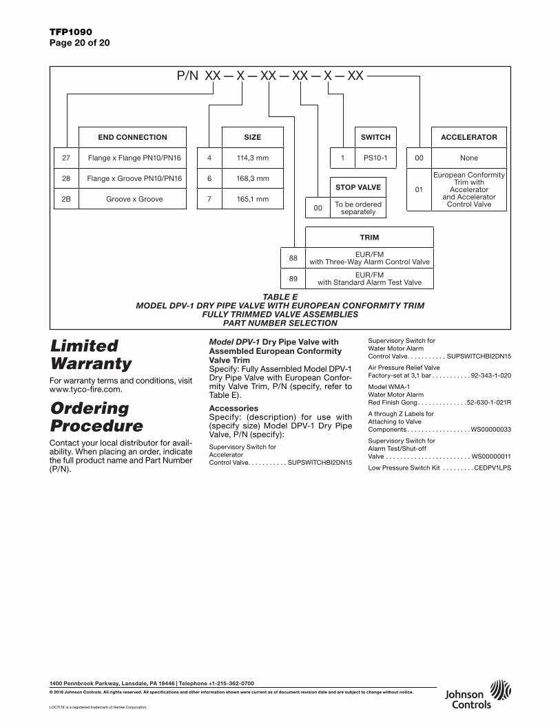
TFP1090Page 20 of 20
LOCTITE is a registered trademark of Henkel Corporation
1400 Pennbrook Parkway, Lansdale, PA 19446 | Telephone +1-215-362-0700
© 2018 Johnson Controls. All rights reserved. All specifications and other information shown were current as of document revision date and are subject to change without notice.
Limited WarrantyFor warranty terms and conditions, visit www.tyco-fire.com.
Ordering ProcedureContact your local distributor for avail-ability. When placing an order, indicate the full product name and Part Number (P/N).
Model DPV-1 Dry Pipe Valve with Assembled European Conformity Valve TrimSpecify: Fully Assembled Model DPV-1 Dry Pipe Valve with European Confor-mity Valve Trim, P/N (specify, refer to Table E).
AccessoriesSpecify: (description) for use with (specify size) Model DPV-1 Dry Pipe Valve, P/N (specify):Supervisory Switch forAcceleratorControl Valve . . . . . . . . . . . SUPSWITCHBI2DN15
Supervisory Switch forWater Motor AlarmControl Valve . . . . . . . . . . . SUPSWITCHBI2DN15
Air Pressure Relief ValveFactory-set at 3,1 bar . . . . . . . . . . . 92-343-1-020
Model WMA-1Water Motor AlarmRed Finish Gong . . . . . . . . . . . . . .52-630-1-021R
A through Z Labels forAttaching to ValveComponents . . . . . . . . . . . . . . . . . . WS00000033
Supervisory Switch forAlarm Test/Shut-offValve . . . . . . . . . . . . . . . . . . . . . . . . WS00000011
Low Pressure Switch Kit . . . . . . . . .CEDPV1LPS
SIZE
4 114,3 mm
6 168,3 mm
7 165,1 mm
TRIM
88 EUR/FM with Three-Way Alarm Control Valve
89 EUR/FM with Standard Alarm Test Valve
STOP VALVE
00 To be ordered separately
SWITCH
1 PS10-1
END CONNECTION
27 Flange x Flange PN10/PN16
28 Flange x Groove PN10/PN16
2B Groove x Groove
P/N XX — X — XX — XX — X — XX
ACCELERATOR
00 None
01
European Conformity Trim with
Accelerator and Accelerator
Control Valve
TABLE E MODEL DPV-1 DRY PIPE VALVE WITH EUROPEAN CONFORMITY TRIM
FULLY TRIMMED VALVE ASSEMBLIES PART NUMBER SELECTION

Appendix A of TFP1090 (08/2018) Summary Instructions (if problems occur, consult full document) DN100, Model DPV-1 Dry Pipe Valve with Three-Way Alarm Test Valve, without Model ACC-1 Accelerator
I. Normal Conditions• The Main Control Valve (A) is opened
and locked.
• The sprinkler system is filled with air and is pressurized.
• The Main Drain Valve (F), and Low Body Drain Valve (L) are closed.
• The Three-Way Alarm Control Valve (E) is in the open position.
• The Pressure Gauge Valves (B) and (C) are open.
• The Pressure Switch Valve (J) is open.
• The Air Supply Control Valve (K) is open.
• System Air Pressure Gauge (G) reads downstream air pressure.
• Water Supply Pressure Gauge (H) reads the upstream water pressure.
II. OperationWhen one or more sprinklers are acti-vated, air pressure is reduced down-stream of the Dry Pipe Valve. When the air pressure is sufficiently reduced, the water pressure overcomes the differen-tial holding the Dry Pipe Valve closed and the Dry Pipe Valve opens to per-mit water flow into the system piping and to be discharged from any open sprinklers. Also, with the Dry Pipe Valve open, water flows through the Alarm Port at the rear of the Dry Pipe Valve to actuate the Waterflow Pressure Alarm Switch (M) and, as applicable, the Water Motor Alarm.
III. Removing System From ServiceStep 1. Close the Main Control Valve (A), close the Air Supply Control Valve (K), and place the Three-Way Alarm Control Valve (E) in the closed position.
Step 2. Drain the system with the Main Drain Valve (F) and by opening all auxil-iary drain valves in the system to make sure that cross-mains and branch lines are drained.
IV. Placing the System Back in ServiceStep 1. Close the auxiliary drain valves after water ceases to discharge, and leave the Main Drain Valve (F) open.
Step 2. Place the Three-Way Alarm Control Valve (E) in the open position.
Step 3. Replace the sprinklers that have operated and the sprinklers close to the fire.
Step 4. Push down on the reset knob (P) to allow the Dry Pipe Valve (D) to re-seat.
Step 5. Via the Air Supply Control Valve (K), pressurize the system with air to 0,7 bar, and then open and close each auxiliary drain valves in the sys-tem piping to drain any remaining water in trapped sections. Also, partially open the Low Body Drain Valve (L) to assure that the riser is completely drained. Close the Low Body Drain Valve (L) as soon as water ceases to discharge.
Step 6. Open the Air Supply Control Valve (K) to restore the system to the normal system air pressure.
Step 7. Partially open the Main Control Valve (A), and then slowly close the Main Drain Valve (F).
Step 8. Fully open the Main Control Valve (A) and lock it open.
Step 9. Reset the fire alarm panel and notify the central alarm station.
V. Weekly TestImportant: Prior to closing any valves or activating any alarms, notify local se-curity guards and the central alarm sta-tion if applicable.
Step 1. Place the Three-Way Alarm Control Valve (E) in the test position, verify that the alarm signal created by the Waterflow Pressure Alarm Switch (M) is visible at the fire panel. If appli-cable, check the sound of the Water Motor Alarm — it must be clear and steady.
Step 2. Place the Three-Way Alarm Control Valve (E) in the open position and verify that the normal supply and system pressures are restored. If the supply pressure is below the normal, use the instructions from the water sup-ply to obtain the usual pressure.
Step 3. Close the Pressure Switch Valve (J) and verify operation of the low air pressure Alarm Switch (N).
Step 4. Return the Pressure Switch Valve (J) to the normally open position after verifying that the alarm signal is visible at the fire panel.
395 mmA
M
L
E
K
J H
376 mm
F
B
G C D P
185 mm
440 mm
N

Appendix B of TFP1090 (08/2018) Summary Instructions (if problems occur, consult full document) DN150, Model DPV-1 Dry Pipe Valve with Three-Way Alarm Test Valve, without Model ACC-1 Accelerator
I. Normal Conditions• The Main Control Valve (A) is opened
and locked.
• The sprinkler system is filled with air and is pressurized.
• The Main Drain Valve (F), and Low Body Drain Valve (L) are closed.
• The Three-Way Alarm Control Valve (E) is in the open position.
• The Pressure Gauge Valves (B) and (C) are open.
• The Pressure Switch Valve (J) is open.
• The Air Supply Control Valve (K) is open.
• System Air Pressure Gauge (G) reads downstream air pressure.
• Water Supply Pressure Gauge (H) reads the upstream water pressure.
II. OperationWhen one or more sprinklers are acti-vated, air pressure is reduced down-stream of the Dry Pipe Valve. When the air pressure is sufficiently reduced, the water pressure overcomes the differen-tial holding the Dry Pipe Valve closed and the Dry Pipe Valve opens to per-mit water flow into the system piping and to be discharged from any open sprinklers. Also, with the Dry Pipe Valve open, water flows through the Alarm Port at the rear of the Dry Pipe Valve to actuate the Waterflow Pressure Alarm Switch (M) and, as applicable, the Water Motor Alarm.
III. Removing System From ServiceStep 1. Close the Main Control Valve (A), close the Air Supply Control Valve (K), and place the Three-Way Alarm Control Valve (E) in the closed position.
Step 2. Drain the system with the Main Drain Valve (F) and by opening all auxil-iary drain valves in the system to make sure that cross-mains and branch lines are drained.
IV. Placing the System Back in ServiceStep 1. Close the auxiliary drain valves after water ceases to discharge, and leave the Main Drain Valve (F) open.
Step 2. Place the Three-Way Alarm Control Valve (E) in the open position.
Step 3. Replace the sprinklers that have operated and the sprinklers close to the fire.
Step 4. Push down on the reset knob (P) to allow the Dry Pipe Valve (D) to re-seat.
Step 5. Via the Air Supply Control Valve (K), pressurize the system with air to 0,7 bar, and then open and close each auxiliary drain valves in the sys-tem piping to drain any remaining water in trapped sections. Also, partially open the Low Body Drain Valve (L) to assure that the riser is completely drained. Close the Low Body Drain Valve (L) as soon as water ceases to discharge.
Step 6. Open the Air Supply Control Valve (K) to restore the system to the normal system air pressure.
Step 7. Partially open the Main Control Valve (A), and then slowly close the Main Drain Valve (F).
Step 8. Fully open the Main Control Valve (A) and lock it open.
Step 9. Reset the fire alarm panel and notify the central alarm station.
V. Weekly TestImportant: Prior to closing any valves or activating any alarms, notify local se-curity guards and the central alarm sta-tion if applicable.
Step 1. Place the Three-Way Alarm Control Valve (E) in the test position, verify that the alarm signal created by the Waterflow Pressure Alarm Switch (M) is visible at the fire panel. If appli-cable, check the sound of the Water Motor Alarm — it must be clear and steady.
Step 2. Place the Three-Way Alarm Control Valve (E) in the open position and verify that the normal supply and system pressures are restored. If the supply pressure is below the normal, use the instructions from the water sup-ply to obtain the usual pressure.
Step 3. Close the Pressure Switch Valve (J) and verify operation of the low air pressure Alarm Switch (N).
Step 4. Return the Pressure Switch Valve (J) to the normally open position after verifying that the alarm signal is visible at the fire panel.
346 mm399 mmA
B
L
F
H
K
J
G C
191 mm
E
M
D
P
480 mm
N

Appendix C of TFP1090 (08/2018) Summary Instructions (if problems occur, consult full document) DN100, Model DPV-1 Dry Pipe Valve with Standard Alarm Test Valve, without Model ACC-1 Accelerator
I. Normal Conditions• The Main Control Valve (A) is opened
and locked.
• The sprinkler system is filled with air and is pressurized.
• The Main Drain Valve (F), and Low Body Drain Valve (L) are closed.
• The Alarm Test Valve (E) is in the closed position.
• The Pressure Gauge Valves (B) and (C) are open.
• The Pressure Switch Valve (J) is open.
• The Air Supply Control Valve (K) is open.
• System Air Pressure Gauge (G) reads downstream air pressure.
• Water Supply Pressure Gauge (H) reads the upstream water pressure.
II. OperationWhen one or more sprinklers are acti-vated, air pressure is reduced down-stream of the Dry Pipe Valve. When the air pressure is sufficiently reduced, the water pressure overcomes the differen-tial holding the Dry Pipe Valve closed and the Dry Pipe Valve opens to per-mit water flow into the system piping and to be discharged from any open sprinklers. Also, with the Dry Pipe Valve open, water flows through the Alarm Port at the rear of the Dry Pipe Valve to actuate the Waterflow Pressure Alarm Switch (M) and, as applicable, the Water Motor Alarm.
Step 7. Fully open the Main Control Valve (A) and lock it open.
Step 8. Reset the fire alarm panel and notify the central alarm station.
V. Weekly TestImportant: Prior to closing any valves or activating any alarms, notify local se-curity guards and the central alarm sta-tion if applicable.
Step 1. Open the Alarm Test Valve (E), verify that the alarm signal created by the Waterflow Pressure Alarm Switch (M) is visible at the fire panel. If appli-cable, check the sound of the Water Motor Alarm — it must be clear and steady.
Step 2. Close the Alarm Test Valve (E), verify that the normal supply and sys-tem pressures are restored. If the sup-ply pressure is below the normal, use the instructions from the water supply to obtain the usual pressure.
Step 3. Close the Pressure Switch Valve (J) and verify operation of the low air pressure Alarm Switch (N).
Step 4. Return the Pressure Switch Valve (J) to the normally open position after verifying that the alarm signal is visible at the fire panel.
III. Removing System From ServiceStep 1. Close the Main Control Valve (A), and close the Air Supply Control Valve (K).
Step 2. Drain the system with the Main Drain Valve (F) and by opening all auxil-iary drain valves in the system to make sure that cross-mains and branch lines are drained.
IV. Placing the System Back in ServiceStep 1. Close the auxiliary drain valves after water ceases to discharge, and leave the Main Drain Valve (F) open.
Step 2. Replace the sprinklers that have operated and the sprinklers close to the fire.
Step 3. Push down on the reset knob (P) to allow the Dry Pipe Valve (D) to re-seat.
Step 4. Via the Air Supply Control Valve (K), pressurize the system with air to 0,7 bar, and then open and close each auxiliary drain valves in the sys-tem piping to drain any remaining water in trapped sections. Also, partially open the Low Body Drain Valve (L) to assure that the riser is completely drained. Close the Low Body Drain Valve (L) as soon as water ceases to discharge.
Step 5. Open the Air Supply Control Valve (K) to restore the system to the normal system air pressure.
Step 6. Partially open the Main Control Valve (A), and then slowly close the Main Drain Valve (F).
407 mm 376 mm 193 mm
H
F
B
PDG C
A
M
L
E
K
JN
440 mm

Appendix D of TFP1090 (08/2018) Summary Instructions (if problems occur, consult full document) DN150, Model DPV-1 Dry Pipe Valve with Standard Alarm Test Valve, without Model ACC-1 Accelerator
I. Normal Conditions• The Main Control Valve (A) is opened
and locked.
• The sprinkler system is filled with air and is pressurized.
• The Main Drain Valve (F), and Low Body Drain Valve (L) are closed.
• The Alarm Test Valve (E) is in the closed position.
• The Pressure Gauge Valves (B) and (C) are open.
• The Pressure Switch Valve (J) is open.
• The Air Supply Control Valve (K) is open.
• System Air Pressure Gauge (G) reads downstream air pressure.
• Water Supply Pressure Gauge (H) reads the upstream water pressure.
II. OperationWhen one or more sprinklers are acti-vated, air pressure is reduced down-stream of the Dry Pipe Valve. When the air pressure is sufficiently reduced, the water pressure overcomes the differen-tial holding the Dry Pipe Valve closed and the Dry Pipe Valve opens to per-mit water flow into the system piping and to be discharged from any open sprinklers. Also, with the Dry Pipe Valve open, water flows through the Alarm Port at the rear of the Dry Pipe Valve to actuate the Waterflow Pressure Alarm Switch (M) and, as applicable, the Water Motor Alarm.
III. Removing System From ServiceStep 1. Close the Main Control Valve (A), and close the Air Supply Control Valve (K).
Step 2. Drain the system with the Main Drain Valve (F) and by opening all auxil-iary drain valves in the system to make sure that cross-mains and branch lines are drained.
IV. Placing the System Back in ServiceStep 1. Close the auxiliary drain valves after water ceases to discharge, and leave the Main Drain Valve (F) open.
Step 2. Replace the sprinklers that have operated and the sprinklers close to the fire.
Step 3. Push down on the reset knob (P) to allow the Dry Pipe Valve (D) to re-seat.
Step 4. Via the Air Supply Control Valve (K), pressurize the system with air to 0,7 bar, and then open and close each auxiliary drain valves in the sys-tem piping to drain any remaining water in trapped sections. Also, partially open the Low Body Drain Valve (L) to assure that the riser is completely drained. Close the Low Body Drain Valve (L) as soon as water ceases to discharge.
Step 5. Open the Air Supply Control Valve (K) to restore the system to the normal system air pressure.
Step 6. Partially open the Main Control Valve (A), and then slowly close the Main Drain Valve (F).
Step 7. Fully open the Main Control Valve (A) and lock it open.
Step 8. Reset the fire alarm panel and notify the central alarm station.
V. Weekly TestImportant: Prior to closing any valves or activating any alarms, notify local se-curity guards and the central alarm sta-tion if applicable.
Step 1. Open the Alarm Test Valve (E), verify that the alarm signal created by the Waterflow Pressure Alarm Switch (M) is visible at the fire panel. If appli-cable, check the sound of the Water Motor Alarm — it must be clear and steady.
Step 2. Close the Alarm Test Valve (E), verify that the normal supply and sys-tem pressures are restored. If the sup-ply pressure is below the normal, use the instructions from the water supply to obtain the usual pressure.
Step 3. Close the Pressure Switch Valve (J) and verify operation of the low air pressure Alarm Switch (N).
Step 4. Return the Pressure Switch Valve (J) to the normally open position after verifying that the alarm signal is visible at the fire panel.
H
A 399 mm
F
B
L
375 mm
K
J
G C
E
193 mm
M
P
D
480 mm
N

Appendix E of TFP1090 (08/2018) Summary Instructions (if problems occur, consult full document) DN100, Model DPV-1 Dry Pipe Valve with Three-Way Alarm Test Valve, with Model ACC-1 Accelerator
I. Normal Conditions• The Main Control Valve (A) is opened
and locked, and the Accelerator Control Valve (S) and Air Supply Control Valve (K) are open.
• The sprinkler system is filled with air and is pressurized.
• The Main Drain Valve (F), and Low Body Drain Valve (L) are closed.
• The Three-Way Alarm Control Valve (E) is in the open position.
• The Pressure Gauge Valves (B) and (C) are open.
• The Pressure Switch Valve (J) is open.
• System Air Pressure Gauge (G) reads downstream air pressure, Water Supply Pressure Gauge (H) reads the upstream water pressure, and Accelerator Air Pressure Gauge (R) reads the accelerator pressure.
II. OperationWhen one or more sprinklers are acti-vated, the accelerator operates to per-mit system air pressure into the Dry Pipe Valve intermediate chamber. Doing so will immediately overcome the ability of the system air pressure to hold the Dry Pipe Valve closed without having to wait for system air pressure to de-cay to approximately 20% of the water supply. The Dry Pipe Valve immediately opens to permit water flow into the sys-tem piping and to be discharged from any open sprinklers. Also, with the Dry Pipe Valve open, water flows to actuate the Waterflow Pressure Alarm Switch (M) and, as applicable, the Water Motor Alarm.
III. Removing System From ServiceStep 1. Close the Main Control Valve (A), close the Air Supply Control Valve (K), close the Accelerator Control Valve (R), and place the Three-Way Alarm Control Valve (E) in the closed position.
Step 2. Drain the system with the Main Drain Valve (F) and by opening all auxil-iary drain valves in the system to make sure that cross-mains and branch lines are drained.
IV. Placing the System Back in ServiceStep 1. Close the auxiliary drain valves after water ceases to discharge, and leave the Main Drain Valve (F) open.
Step 2. Place the Three-Way Alarm Control Valve (E) in the open position.
Step 3. Replace the sprinklers that have operated and the sprinklers close to the fire.
Step 4. Push down on the reset knob (P) to allow the Dry Pipe Valve (D) to re-seat.
Step 5. Via the Air Supply Control Valve (K), pressurize the system with air to 0,7 bar, and then open and close each auxiliary drain valves in the sys-tem piping to drain any remaining water in trapped sections. Also, partially open the Low Body Drain Valve (L) to assure that the riser is completely drained. Close the Low Body Drain Valve (L) as soon as water ceases to discharge.
Step 6. Open the Air Supply Control Valve (K) to restore the system to the normal system air pressure.
Step 7. Reset accelerator (Q) using the instruction on its resetting label.
Step 8. Partially open the Main Control Valve (A), and then slowly close the Main Drain Valve (F).
Step 9. Fully open the Main Control Valve (A) and lock it open.
Step 10. Reset the fire alarm panel and notify the central alarm station.
V. Weekly TestImportant: Prior to closing any valves or activating any alarms, notify local se-curity guards and the central alarm sta-tion if applicable.
Step 1. Place the Three-Way Alarm Control Valve (E) in the test position, verify that the alarm signal created by the Waterflow Pressure Alarm Switch (M) is visible at the fire panel. If appli-cable, check the sound of the Water Motor Alarm — it must be clear and steady.
Step 2. Place the Three-Way Alarm Control Valve (E) in the open position and verify that the normal supply and system pressures are restored. If the supply pressure is below the normal, use the instructions from the water sup-ply to obtain the usual pressure.
Step 3. Close the Pressure Switch Valve (J) and verify operation of the low air pressure Alarm Switch (N).
Step 4. Return the Pressure Switch Valve (J) to the normally open position after verifying that the alarm signal is visible at the fire panel.
395 mmA
M
L
E
K
J
Q
S
R
H
376 mm
F
B
G C D P
790 mm
185 mm
N

Appendix F of TFP1090 (08/2018) Summary Instructions (If problems occur, consult full document) DN150, Model DPV-1 Dry Pipe Valve with Three-Way Alarm Test Valve, with Model ACC-1 Accelerator
I. Normal Conditions• The Main Control Valve (A) is opened
and locked, and the Accelerator Control Valve (S) and Air Supply Control Valve (K) are open.
• The sprinkler system is filled with air and is pressurized.
• The Main Drain Valve (F), and Low Body Drain Valve (L) are closed.
• The Three-Way Alarm Control Valve (E) is in the open position.
• The Pressure Gauge Valves (B) and (C) are open.
• The Pressure Switch Valve (J) is open.
• System Air Pressure Gauge (G) reads downstream air pressure, Water Supply Pressure Gauge (H) reads the upstream water pressure, and Accelerator Air Pressure Gauge (R) reads the accelerator pressure.
II. OperationWhen one or more sprinklers are acti-vated, the accelerator operates to per-mit system air pressure into the Dry Pipe Valve intermediate chamber. Doing so will immediately overcome the ability of the system air pressure to hold the Dry Pipe Valve closed without having to wait for system air pressure to de-cay to approximately 20% of the water supply. The Dry Pipe Valve immediately opens to permit water flow into the sys-tem piping and to be discharged from any open sprinklers. Also, with the Dry Pipe Valve open, water flows to actuate the Waterflow Pressure Alarm Switch (M) and, as applicable, the Water Motor Alarm.
III. Removing System From ServiceStep 1. Close the Main Control Valve (A), close the Air Supply Control Valve (K), close the Accelerator Control Valve (R), and place the Three-Way Alarm Control Valve (E) in the closed position.
Step 2. Drain the system with the Main Drain Valve (F) and by opening all auxil-iary drain valves in the system to make sure that cross-mains and branch lines are drained.
IV. Placing the System Back in ServiceStep 1. Close the auxiliary drain valves after water ceases to discharge, and leave the Main Drain Valve (F) open.
Step 2. Place the Three-Way Alarm Control Valve (E) in the open position.
Step 3. Replace the sprinklers that have operated and the sprinklers close to the fire.
Step 4. Push down on the reset knob (P) to allow the Dry Pipe Valve (D) to re-seat.
Step 5. Via the Air Supply Control Valve (K), pressurize the system with air to 0,7 bar, and then open and close each auxiliary drain valves in the sys-tem piping to drain any remaining water in trapped sections. Also, partially open the Low Body Drain Valve (L) to assure that the riser is completely drained. Close the Low Body Drain Valve (L) as soon as water ceases to discharge.
Step 6. Open the Air Supply Control Valve (K) to restore the system to the normal system air pressure.
Step 7. Reset accelerator (Q) using the instruction on its resetting label.
Step 8. Partially open the Main Control Valve (A), and then slowly close the Main Drain Valve (F).
Step 9. Fully open the Main Control Valve (A) and lock it open.
Step 10. Reset the fire alarm panel and notify the central alarm station.
V. Weekly TestImportant: Prior to closing any valves or activating any alarms, notify local se-curity guards and the central alarm sta-tion if applicable.
Step 1. Place the Three-Way Alarm Control Valve (E) in the test position, verify that the alarm signal created by the Waterflow Pressure Alarm Switch (M) is visible at the fire panel. If appli-cable, check the sound of the Water Motor Alarm — it must be clear and steady.
Step 2. Place the Three-Way Alarm Control Valve (E) in the open position and verify that the normal supply and system pressures are restored. If the supply pressure is below the normal, use the instructions from the water sup-ply to obtain the usual pressure.
Step 3. Close the Pressure Switch Valve (J) and verify operation of the low air pressure Alarm Switch (N).
Step 4. Return the Pressure Switch Valve (J) to the normally open position after verifying that the alarm signal is visible at the fire panel.
399 mmA
B
L
F
H
K
Q
J
S
R
346 mm
E
M
G C D
P
191 mm
824 mm
N

Appendix G of TFP1090 (08/2018) Summary Instructions (If problems occur, consult full document) DN100, Model DPV-1 Dry Pipe Valve with Standard Alarm Test Valve, with Model ACC-1 Accelerator
I. Normal Conditions• The Main Control Valve (A) is opened
and locked, and the Accelerator Control Valve (S) and Air Supply Control Valve (K) are open.
• The sprinkler system is filled with air and is pressurized.
• The Main Drain Valve (F), and Low Body Drain Valve (L) are closed.
• The Alarm Test Valve (E) is in the closed position.
• The Pressure Gauge Valves (B) and (C) are open.
• The Pressure Switch Valve (J) is open.
• System Air Pressure Gauge (G) reads downstream air pressure, Water Supply Pressure Gauge (H) reads the upstream water pressure, and Accelerator Air Pressure Gauge (R) reads the accelerator pressure.
II. OperationWhen one or more sprinklers are acti-vated, the accelerator operates to per-mit system air pressure into the Dry Pipe Valve intermediate chamber. Doing so will immediately overcome the ability of the system air pressure to hold the Dry Pipe Valve closed without having to wait for system air pressure to de-cay to approximately 20% of the water supply. The Dry Pipe Valve immediately opens to permit water flow into the sys-tem piping and to be discharged from any open sprinklers. Also, with the Dry Pipe Valve open, water flows to actuate the Waterflow Pressure Alarm Switch (M) and, as applicable, the Water Motor Alarm.
III. Removing System From ServiceStep 1. Close the Main Control Valve (A), close the Air Supply Control Valve (K), and close the Accelerator Control Valve (R).
Step 2. Drain the system with the Main Drain Valve (F) and by opening all auxil-iary drain valves in the system to make sure that cross-mains and branch lines are drained.
IV. Placing the System Back in ServiceStep 1. Close the auxiliary drain valves after water ceases to discharge, and leave the Main Drain Valve (F) open.
Step 2. Replace the sprinklers that have operated and the sprinklers close to the fire.
Step 3. Push down on the reset knob (P) to allow the Dry Pipe Valve (D) to re-seat.
Step 4. Via the Air Supply Control Valve (K), pressurize the system with air to 0,7 bar, and then open and close each auxiliary drain valves in the sys-tem piping to drain any remaining water in trapped sections. Also, partially open the Low Body Drain Valve (L) to assure that the riser is completely drained. Close the Low Body Drain Valve (L) as soon as water ceases to discharge.
Step 5. Open the Air Supply Control Valve (K) to restore the system to the normal system air pressure.
Step 6. Reset accelerator (Q) using the instruction on its resetting label.
Step 7. Partially open the Main Control Valve (A), and then slowly close the Main Drain Valve (F).
Step 8. Fully open the Main Control Valve (A) and lock it open.
Step 9. Reset the fire alarm panel and notify the central alarm station.
V. Weekly TestImportant: Prior to closing any valves or activating any alarms, notify local se-curity guards and the central alarm sta-tion if applicable.
Step 1. Open the Alarm Test Valve (E), verify that the alarm signal created by the Waterflow Pressure Alarm Switch (M) is visible at the fire panel. If appli-cable, check the sound of the Water Motor Alarm — it must be clear and steady.
Step 2. Close the Alarm Test Valve (E), verify that the normal supply and sys-tem pressures are restored. If the sup-ply pressure is below the normal, use the instructions from the water supply to obtain the usual pressure.
Step 3. Close the Pressure Switch Valve (J) and verify operation of the low air pressure Alarm Switch (N).
Step 4. Return the Pressure Switch Valve (J) to the normally open position after verifying that the alarm signal is visible at the fire panel.
407 mm 376 mm 193 mm
790 mmH
F
B
PDG C
A
M
L
E
K
J
S
Q
R
N

Appendix H of TFP1090 (08/2018) Summary Instructions (if problems occur, consult full document) DN150, Model DPV-1 Dry Pipe Valve with Standard Alarm Test Valve, with Model ACC-1 Accelerator
I. Normal Conditions• The Main Control Valve (A) is opened
and locked, and the Accelerator Control Valve (S) and Air Supply Control Valve (K) are open.
• The sprinkler system is filled with air and is pressurized.
• The Main Drain Valve (F), and Low Body Drain Valve (L) are closed.
• The Alarm Test Valve (E) is in the closed position.
• The Pressure Gauge Valves (B) and (C) are open.
• The Pressure Switch Valve (J) is open.
• System Air Pressure Gauge (G) reads downstream air pressure, Water Supply Pressure Gauge (H) reads the upstream water pressure, and Accelerator Air Pressure Gauge (R) reads the accelerator pressure.
II. OperationWhen one or more sprinklers are acti-vated, the accelerator operates to per-mit system air pressure into the Dry Pipe Valve intermediate chamber. Doing so will immediately overcome the ability of the system air pressure to hold the Dry Pipe Valve closed without having to wait for system air pressure to de-cay to approximately 20% of the water supply. The Dry Pipe Valve immediately opens to permit water flow into the sys-tem piping and to be discharged from any open sprinklers. Also, with the Dry Pipe Valve open, water flows to actuate the Waterflow Pressure Alarm Switch (M) and, as applicable, the Water Motor Alarm.
III. Removing System From ServiceStep 1. Close the Main Control Valve (A), close the Air Supply Control Valve (K), and close the Accelerator Control Valve (R).
Step 2. Drain the system with the Main Drain Valve (F) and by opening all auxil-iary drain valves in the system to make sure that cross-mains and branch lines are drained.
IV. Placing the System Back in ServiceStep 1. Close the auxiliary drain valves after water ceases to discharge, and leave the Main Drain Valve (F) open.
Step 2. Replace the sprinklers that have operated and the sprinklers close to the fire.
Step 3. Push down on the reset knob (P) to allow the Dry Pipe Valve (D) to re-seat.
Step 4. Via the Air Supply Control Valve (K), pressurize the system with air to 0,7 bar, and then open and close each auxiliary drain valves in the sys-tem piping to drain any remaining water in trapped sections. Also, partially open the Low Body Drain Valve (L) to assure that the riser is completely drained. Close the Low Body Drain Valve (L) as soon as water ceases to discharge.
Step 5. Open the Air Supply Control Valve (K) to restore the system to the normal system air pressure.
Step 6. Reset accelerator (Q) using the instruction on its resetting label.
Step 7. Partially open the Main Control Valve (A), and then slowly close the Main Drain Valve (F).
Step 8. Fully open the Main Control Valve (A) and lock it open.
Step 9. Reset the fire alarm panel and notify the central alarm station.
V. Weekly TestImportant: Prior to closing any valves or activating any alarms, notify local se-curity guards and the central alarm sta-tion if applicable.
Step 1. Open the Alarm Test Valve (E), verify that the alarm signal created by the Waterflow Pressure Alarm Switch (M) is visible at the fire panel. If appli-cable, check the sound of the Water Motor Alarm — it must be clear and steady.
Step 2. Close the Alarm Test Valve (E), verify that the normal supply and sys-tem pressures are restored. If the sup-ply pressure is below the normal, use the instructions from the water supply to obtain the usual pressure.
Step 3. Close the Pressure Switch Valve (J) and verify operation of the low air pressure Alarm Switch (N).
Step 4. Return the Pressure Switch Valve (J) to the normally open position after verifying that the alarm signal is visible at the fire panel.
H
A 399 mm
F
B
L
375 mm
K
J
S
R
Q
G C
E
193 mm
M
P
D
824 mm
N