Embed Size (px)
Citation preview
Model Driven Development for Embedded Systems
KUNIHIHIKO ITO
Department of Electronics Engineering and Computer Science, Graduate School of Engineering
Shibaura Institute of Technology
307 Fukasaku, Minuma-ku, Saitama-City, Saitama 337-8570, Japan
SAEKO MATSUURA
Department of Electronic Information Systems, College of System Engineering and Science
Shibaura Institute of Technology
307 Fukasaku Minuma-ku, Saitama-City, Saitama 337-8570, Japan
Abstract: - It is important for developing enterprise systems to fully analyze at an early stage the business
workflows that describe interactions involving systems and their users. This is also important when developing
embedded systems, which consist of various hardware components, their environment, and control software.
Many combinations of sensors and actuators can be used to implement the requirements, and the control software
will be different for every combination. At the requirements analysis phase, it is difficult to adequately test all
possible combinations of hardware components. Recently, MDD (Model Driven Development) has become a
promising approach for system development. Many researchers actively apply UML (Unified Modeling
Language) to embedded systems, and model transformation is expected to determine the best combinations of
modeling elements that depend on both the hardware architecture and the system environment. Executable UML is
a key technology for expressing application domains in a platform-independent manner with formal action
semantics using techniques such as class diagrams and state machine diagrams. This paper proposes a
development method for embedded systems based on MDD in which the models are executable and testable. The
effectiveness of our method is demonstrated through the development of a maze robot.
Key-Words: - Model-driven development, Unified modeling language, Embedded systems, Executable UML,
Simulation, Model transformation
1 Introduction It is important for developing enterprise systems to
fully analyze at an early stage the business workflows
that describe interactions involving systems and their
users. This is also important when developing
embedded systems, which consist of various hardware
components, their environment, and control software.
Many combinations of sensors and actuators can be
used to implement the requirements, and the control
software will be different for every combination. At
the requirements analysis phase, it is difficult to
adequately test all possible combinations of hardware
components. Recently, MDD (Model Driven
Development) has become a promising approach for
system development. Many researchers actively apply
UML (Unified Modeling Language) to embedded
systems, and model transformation is expected to
determine the best combinations of modeling elements
that depend on both the hardware architecture and the
system environment. Executable UML [3] is a key
technology for expressing application domains in a
platform-independent manner with formal action
semantics using techniques such as class diagrams and
state machine diagrams. This paper proposes a
development method for embedded systems based on
MDD in which the models are executable and testable.
The effectiveness of our method is demonstrated
through the development of a maze robot.
The remainder of the paper is organized as follows.
Section 2 presents the challenges in current
development methods for embedded systems in UML.
Section 3 describes our development method for an
embedded system based on MDD by applying it to the
development of a maze robot. Section 4 discusses the
effectiveness of our method and the need for future
research.
RECENT ADVANCES in SOFTWARE ENGINEERING, PARALLEL and DISTRIBUTED SYSTEMS
ISSN: 1790-5117 102 ISBN: 978-960-474-156-4
2 Challenges In Embedded Systems
Development In UML Executable UML, which is an extension of UML that
executes models directly, is widely used as a tool for
MDD. It is a key technology for expressing
application domains in a platform-independent
manner with formal action semantics using techniques
such as class diagrams and state machine diagrams.
However, it shares with object-oriented analysis the
problem that it is difficult for developers to extract
appropriate classes that satisfy the system
requirements.
Use-case analysis specifies the requirements of
enterprise systems by analyzing the business
workflows that describe the interactions of systems
and their users. In embedded system development, the
system consists of various hardware components, their
environment, and control software. The interactions
are difficult to specify unless the software interface
between the hardware components and their
environment is already determined. Moreover, the
performance of the specified hardware components
can seriously affect the control software. Executable
UML can validate the adequacy of the system
requirements by simulating not the code level but the
model level. However, to test various combinations of
the hardware components and their environment, we
need a systematic method for extracting classes.
For example, a maze robot is an autonomous mobile
robot that can travel through a maze and exit from it.
In other words, the robot is required to implement a
maze-solving algorithm. Such a robot can be
constructed using various hardware components such
as different types and numbers of sensors. However, at
the requirements analysis phase, it is difficult to
adequately test all possible combinations of hardware
components. Moreover, if the design rationale is
unclear, it is difficult to easily deal with changes in the
requirements.
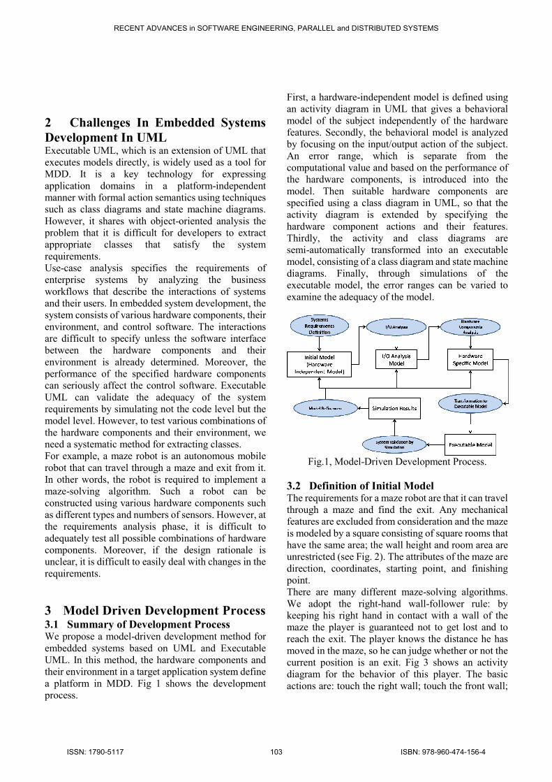
3 Model Driven Development Process 3.1 Summary of Development Process We propose a model-driven development method for
embedded systems based on UML and Executable
UML. In this method, the hardware components and
their environment in a target application system define
a platform in MDD. Fig 1 shows the development
process.
First, a hardware-independent model is defined using
an activity diagram in UML that gives a behavioral
model of the subject independently of the hardware
features. Secondly, the behavioral model is analyzed
by focusing on the input/output action of the subject.
An error range, which is separate from the
computational value and based on the performance of
the hardware components, is introduced into the
model. Then suitable hardware components are
specified using a class diagram in UML, so that the
activity diagram is extended by specifying the
hardware component actions and their features.
Thirdly, the activity and class diagrams are
semi-automatically transformed into an executable
model, consisting of a class diagram and state machine
diagrams. Finally, through simulations of the
executable model, the error ranges can be varied to
examine the adequacy of the model.
Fig.1, Model-Driven Development Process.
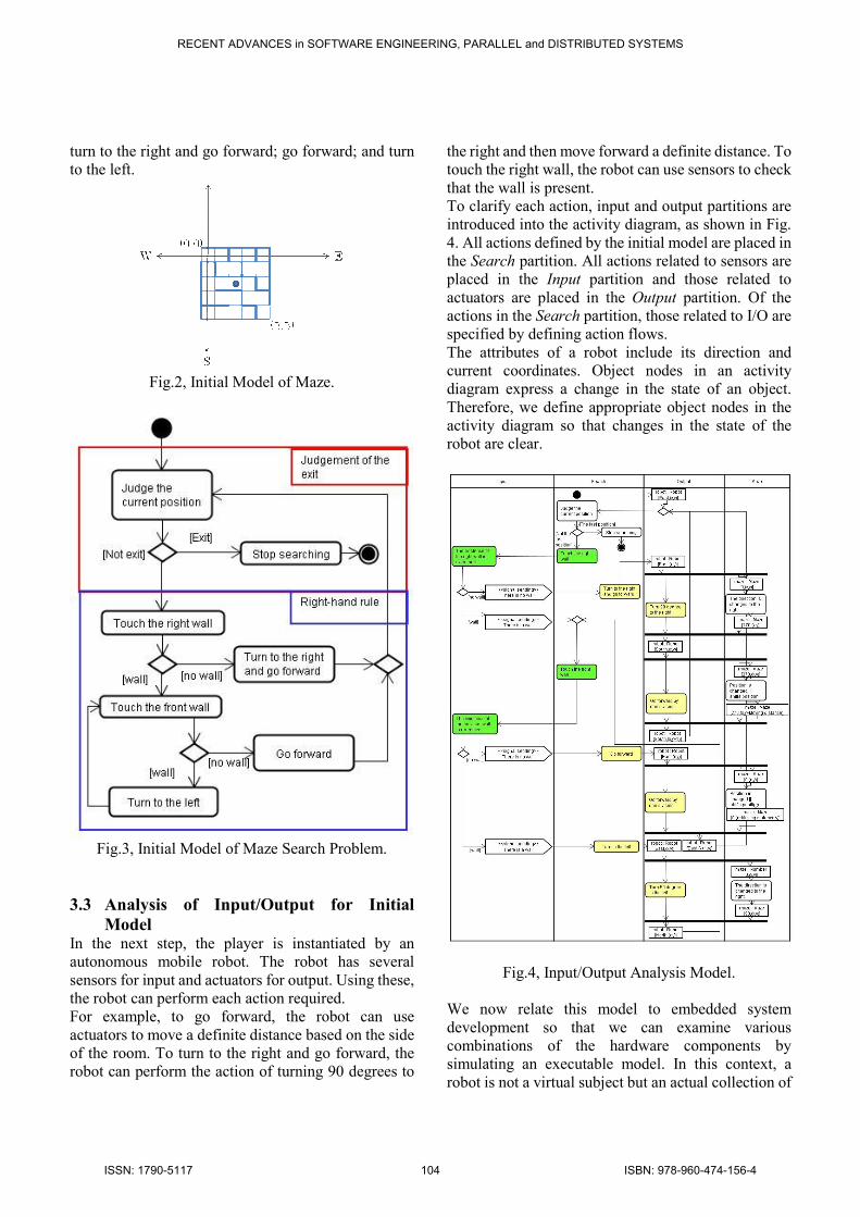
3.2 Definition of Initial Model The requirements for a maze robot are that it can travel
through a maze and find the exit. Any mechanical
features are excluded from consideration and the maze
is modeled by a square consisting of square rooms that
have the same area; the wall height and room area are
unrestricted (see Fig. 2). The attributes of the maze are
direction, coordinates, starting point, and finishing
point.
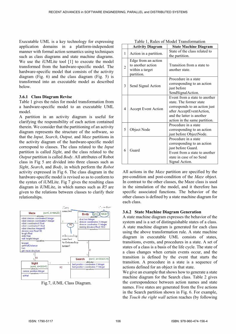
There are many different maze-solving algorithms.
We adopt the right-hand wall-follower rule: by
keeping his right hand in contact with a wall of the
maze the player is guaranteed not to get lost and to
reach the exit. The player knows the distance he has
moved in the maze, so he can judge whether or not the
current position is an exit. Fig 3 shows an activity
diagram for the behavior of this player. The basic
actions are: touch the right wall; touch the front wall;
RECENT ADVANCES in SOFTWARE ENGINEERING, PARALLEL and DISTRIBUTED SYSTEMS
ISSN: 1790-5117 103 ISBN: 978-960-474-156-4
turn to the right and go forward; go forward; and turn
to the left.
Fig.2, Initial Model of Maze.
Fig.3, Initial Model of Maze Search Problem.
3.3 Analysis of Input/Output for Initial
Model In the next step, the player is instantiated by an
autonomous mobile robot. The robot has several
sensors for input and actuators for output. Using these,
the robot can perform each action required.
For example, to go forward, the robot can use
actuators to move a definite distance based on the side
of the room. To turn to the right and go forward, the
robot can perform the action of turning 90 degrees to
the right and then move forward a definite distance. To
touch the right wall, the robot can use sensors to check
that the wall is present.
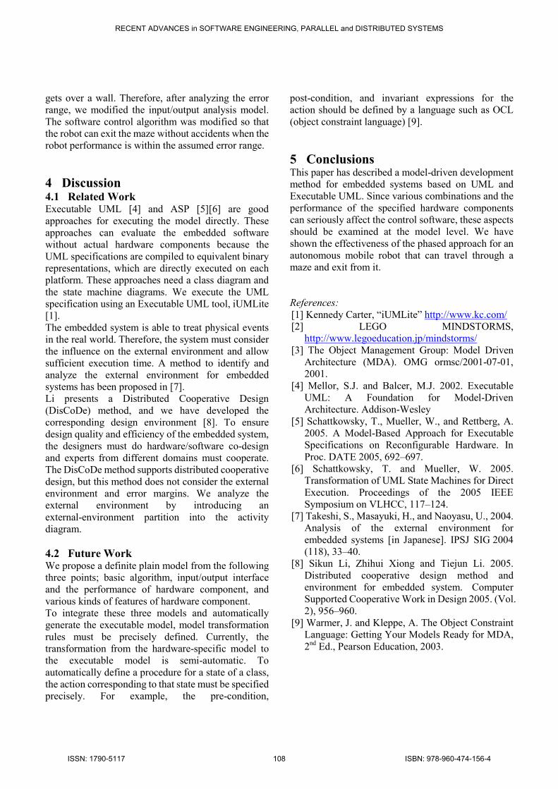
To clarify each action, input and output partitions are
introduced into the activity diagram, as shown in Fig.
4. All actions defined by the initial model are placed in
the Search partition. All actions related to sensors are
placed in the Input partition and those related to
actuators are placed in the Output partition. Of the
actions in the Search partition, those related to I/O are
specified by defining action flows.
The attributes of a robot include its direction and
current coordinates. Object nodes in an activity
diagram express a change in the state of an object.
Therefore, we define appropriate object nodes in the
activity diagram so that changes in the state of the
robot are clear.
Fig.4, Input/Output Analysis Model.
We now relate this model to embedded system
development so that we can examine various
combinations of the hardware components by
simulating an executable model. In this context, a
robot is not a virtual subject but an actual collection of
RECENT ADVANCES in SOFTWARE ENGINEERING, PARALLEL and DISTRIBUTED SYSTEMS
ISSN: 1790-5117 104 ISBN: 978-960-474-156-4

hardware components. Therefore, even if the software
interface between the hardware components and their
environment is determined, the performance of the
components can seriously affect the control software.
In other words, the difference between the
computational output value and the output result
produced by an actual robot should be modeled in the
activity diagram and needs to be examined. We
introduce a Maze partition into the activity diagram to
specify error ranges based on the performance of the
hardware components. Moreover, a Maze class is
added to the class diagram, and this class has attributes
such as direction and coordinates, which are closely
related to the attributes in the Robot class. When a
robot uses actuators to move a definite distance, the
Maze object records a value and the error range.
However, this paper does not discuss the error ranges
of the input components.
3.4 Selection of Suitable Hardware
Components In this experiment, the robot is constructed by LEGO
MINDSTORMS NXT [2], which has four types of
sensors: touch, ultrasonic, sound, and light. The sensor
must be able to check for the presence of a wall, so
only the touch and ultrasonic sensors are suitable. We
will use an ultrasonic sensor.
The robot must be able to go forward a specified
distance and turn to the right or to the left. Thus, it is
designed similarly to a front-wheel-drive car.
At this stage, we have the following constraints on the
attributes of the hardware components and their
environment. It suffices for the robot to satisfy these
constraints:
- The side distance of the maze is greater
than or equal to the width of the robot.
- The wall height is greater than or equal to
the height of the sensor on the robot.
- The side distance equals the moving
distance of the robot.
Based on the above analysis, the class diagram shown
in Fig 5 is extended. The robot class has ten attributes.
Of these, division coordinatesX, division coordinatesY,
and direction change their values when certain actions
are performed. Direction is expressed by an
enumeration type as shown in Fig. 5. The other
attributes, which are set at the system start, are
invariant.
The Maze class also has ten attributes. Of these, robot
division coordinatesX, robot division coordinatesY,
and robot direction are absolute values and include an
error range based on the performance of the hardware
components. Robot direction is expressed as an angle
from 0 to 360 degrees.
- maze structure : int[][]
- wall height : int
- side : double
- length : double
- division size : double
- robot direction : Angle
- robot coordinatesY : double
- robot coordinatesX : double
- robot division coordinatesY : int
- robot division coordinatesX : int
Maze
- sensor position : int
- length : int
- height : int
- width : int
- moving distance : double
- last position coordinatesY : int
- last position coordinatesX : int
- direction : Direction
- division coordinatesY : int
- division coordinatesX : int
Robot
+ south : int = 270
+ west : int = 180
+ north : int = 90
+ east : int = 0
Angle
+ WEST
+ SOUTH
+ NORTH
+ EAST
<<enumeration>>
Direction
Fig.5, Class Diagram for Hardware Components.
3.5 Definition of Hardware-Specific Model The hardware-specific model is defined by
transforming the I/O analysis model shown in Fig. 4.
Fig 6 shows the hardware-specific model when an
ultrasonic sensor is selected as the input device of the
robot. Because an ultrasonic sensor can sense that
there is a wall without touching it, the robot does not
need to go forward when checking for the presence of
a wall. However, the sensor has to be fitted on the front
of the body and to satisfy the constraint relating to the
wall height. To touch the right wall, the robot has to
turn 90 degrees to the right and then measure the
distance to the wall.
BodySearchInput
Touch the right
wall[The distance to
the wall >= one
division size]
[The distance to the
wall < one division size]
Turn 90 degree
to the right
Go forward by
one division
The distance to the
wall is measured
<<signal sending>>
There is a wall
<<signal sending>>
There is no wall
<<signal receipt>>
There is no wall
<<signal receipt>>
There is a wall
Touch the front
wallTurn 90 degree
to the left
Judge the current
position
[Not exit]
Stop searching[Exit]
Go forward
[North,(x,y)]
robot : Robot
[East,(x,y)]
robot : Robot
[East,(x+1,y)]
robot : Robot
[North,(x,y)]
robot : Robot
[division coordinatesX,division coordinatesY]
robot : Robot
Fig.6, Hardware-Specific Model.
3.6 Transformation to Executable UML
Model
RECENT ADVANCES in SOFTWARE ENGINEERING, PARALLEL and DISTRIBUTED SYSTEMS
ISSN: 1790-5117 105 ISBN: 978-960-474-156-4
Executable UML is a key technology for expressing
application domains in a platform-independent
manner with formal action semantics using techniques
such as class diagrams and state machine diagrams.
We use the iUMLite tool [1] to execute the model
transformed from the hardware-specific model. The
hardware-specific model that consists of the activity
diagram (Fig. 6) and the class diagram (Fig. 5) is
transformed into an executable model as described
below.
3.6.1 Class Diagram Revise
Table 1 gives the rules for model transformation from
a hardware-specific model to an executable UML
model.
A partition in an activity diagram is useful for
clarifying the responsibility of each action contained
therein. We consider that the partitioning of an activity
diagram represents the structure of the software, so
that the Input, Search, Output, and Maze partitions in
the activity diagram of the hardware-specific model
correspond to classes. The class related to the Input
partition is called Sight, and the class related to the
Output partition is called Body. All attributes of Robot
class in Fig 5 are divided into three classes such as
Sight, Search, and Body, in which perform the Robot
activity expressed in Fig 6. The class diagram in the
hardware-specific model is revised so as to conform to
the syntax of iUMLite. Fig 7 gives the resulting class
diagram in iUMLite, in which names such as R5 are
given to the relations between classes to clarify their
relationships.
Fig.7, iUML Class Diagram.
Table 1, Rules of Model Transformation Activity Diagram State Machine Diagram
1 Action in a partition. State of the class related to
the partition.
2
Edge from an action
to another action
within a target
partition.
Transition from a state to
another state.
3 Send Signal Action
Procedure in a state
corresponding to an action
just before
SendSignalAction.
4 Accept Event Action
Event from a state to another
state. The former state
corresponds to an action just
after AcceptEventAction,
and the latter is another
action in the same partition.
5 Object Node
Procedure in a state
corresponding to an action
just before ObjectNode.
6 Guard
Procedure in a state
corresponding to an action
just before Guard.
Event from a state to another
state in case of no Send
Signal Action.
All actions in the Maze partition are specified by the
pre-condition and post-condition of the Maze object.
In contrast to the other classes, the Maze class is used
in the simulation of the model, and it therefore has
specific associated functions. The behavior of the
other classes is defined by a state machine diagram for
each class.
3.6.2 State Machine Diagram Generation
A state machine diagram expresses the behavior of the
system and is a set of distinguishable states of a class.
A state machine diagram is generated for each class
using the above transformation rule. A state machine
diagram in executable UML consists of states,
transitions, events, and procedures in a state. A set of
states of a class is a basis of the life cycle. The state of
a class changes when certain events occur, and the
transition is defined by the event that starts the
transition. A procedure in a state is a sequence of
actions defined for an object in that state.
We give an example that shows how to generate a state
machine diagram for the Search class. Table 2 gives
the correspondence between action names and state
names. Five states are generated from the five actions
in the Search partition shown in Fig. 6. For example,
the Touch the right wall action reaches (by following
RECENT ADVANCES in SOFTWARE ENGINEERING, PARALLEL and DISTRIBUTED SYSTEMS
ISSN: 1790-5117 106 ISBN: 978-960-474-156-4

the edges) both Go forward and Touch the front wall.
Therefore, two transitions named noWall() and wall()
are generated. These names are generated from Accept
Event Action according to Rule 4 in Table 1. An event
that causes the transition is The distance to the wall is
measured in the Input partition. Go forward is a
transition from the RightTouch state to the Forward
state, and Touch the front wall is a transition from the
RightTouch state to the ForwardTouch state.
Table 2. Name Transformation
Action State
Judge the current position CheckingGoal
Stop searching Stop
Touch the right wall RightTouch
Go forward Forward
Touch the front wall ForwardTouch
Fig.8, State Machine Diagram for Search Class.
As shown in Rule 4 in Table 1, Send Signal Action is
transformed to a procedure of a state. As shown in Fig.
6, The distance of the wall is measured becomes a state
named Checking Wall in the Sight class and the action
generates two kinds of events according to the sensor
value. These events cause the above transitions in the
state machine diagram of the Search class. Fig 9 gives
the definition of Checking Wall.
Rule 5 generates a procedure in a state if the
corresponding action is specified by the pre-condition
and post-condition of the object.
According to Rule 6, the state corresponding to Judge
the current position has a procedure specified by the
Guard conditions (see the CheckingGoal state in Fig.
8).
Fig.9, State Machine Diagram for Sight Class.
3.7 Verification by Execution of Model To simulate the generated executable UML model, we
must define methods to initialize and test the system.
The initializing method involves operations specified
by the action description language, such as instance
creation, field initialization, and instance relationship.
The testing method involves a sequence of operations
that examine the adequacy of the model by varying the
error range. The iUMLite tool provides information
such as instance field values and the states of any
object. Moreover, the execution history is recorded for
our investigation, so that we can examine the effects of
varying values within the error range. This error is
caused by the difference of the current coordinates
between the Robot object and the Maze object. The
difference, which depends on a value within the error
range, leads a wrong judgment of the action "The
existence of the right wall is examined" in the Input
partition of Fig 4.
In the simulation environment, we can test the
maze-solving algorithm by assuming that the error
range is empty. This test makes it clear that the
algorithm is adequately defined.
After we have confirmed the correctness of the
algorithm, the robot behavior is examined by changing
the values of the Maze object. We showed that an
impossible state occurs by confirming that the robot
RECENT ADVANCES in SOFTWARE ENGINEERING, PARALLEL and DISTRIBUTED SYSTEMS
ISSN: 1790-5117 107 ISBN: 978-960-474-156-4
gets over a wall. Therefore, after analyzing the error
range, we modified the input/output analysis model.
The software control algorithm was modified so that
the robot can exit the maze without accidents when the
robot performance is within the assumed error range.
4 Discussion 4.1 Related Work Executable UML [4] and ASP [5][6] are good
approaches for executing the model directly. These
approaches can evaluate the embedded software
without actual hardware components because the
UML specifications are compiled to equivalent binary
representations, which are directly executed on each
platform. These approaches need a class diagram and
the state machine diagrams. We execute the UML
specification using an Executable UML tool, iUMLite
[1].
The embedded system is able to treat physical events
in the real world. Therefore, the system must consider
the influence on the external environment and allow
sufficient execution time. A method to identify and
analyze the external environment for embedded
systems has been proposed in [7].
Li presents a Distributed Cooperative Design
(DisCoDe) method, and we have developed the
corresponding design environment [8]. To ensure
design quality and efficiency of the embedded system,
the designers must do hardware/software co-design
and experts from different domains must cooperate.
The DisCoDe method supports distributed cooperative
design, but this method does not consider the external
environment and error margins. We analyze the
external environment by introducing an
external-environment partition into the activity
diagram.
4.2 Future Work We propose a definite plain model from the following
three points; basic algorithm, input/output interface
and the performance of hardware component, and
various kinds of features of hardware component.
To integrate these three models and automatically
generate the executable model, model transformation
rules must be precisely defined. Currently, the
transformation from the hardware-specific model to
the executable model is semi-automatic. To
automatically define a procedure for a state of a class,
the action corresponding to that state must be specified
precisely. For example, the pre-condition,
post-condition, and invariant expressions for the
action should be defined by a language such as OCL
(object constraint language) [9].
5 Conclusions This paper has described a model-driven development
method for embedded systems based on UML and
Executable UML. Since various combinations and the
performance of the specified hardware components
can seriously affect the control software, these aspects
should be examined at the model level. We have
shown the effectiveness of the phased approach for an
autonomous mobile robot that can travel through a
maze and exit from it.
References:
[1] Kennedy Carter, “iUMLite” http://www.kc.com/
[2] LEGO MINDSTORMS,
http://www.legoeducation.jp/mindstorms/
[3] The Object Management Group: Model Driven
Architecture (MDA). OMG ormsc/2001-07-01,
2001.
[4] Mellor, S.J. and Balcer, M.J. 2002. Executable
UML: A Foundation for Model-Driven
Architecture. Addison-Wesley
[5] Schattkowsky, T., Mueller, W., and Rettberg, A.
2005. A Model-Based Approach for Executable
Specifications on Reconfigurable Hardware. In
Proc. DATE 2005, 692–697.
[6] Schattkowsky, T. and Mueller, W. 2005.
Transformation of UML State Machines for Direct
Execution. Proceedings of the 2005 IEEE
Symposium on VLHCC, 117–124.
[7] Takeshi, S., Masayuki, H., and Naoyasu, U., 2004.
Analysis of the external environment for
embedded systems [in Japanese]. IPSJ SIG 2004
(118), 33–40.
[8] Sikun Li, Zhihui Xiong and Tiejun Li. 2005.
Distributed cooperative design method and
environment for embedded system. Computer
Supported Cooperative Work in Design 2005. (Vol.
2), 956–960.
[9] Warmer, J. and Kleppe, A. The Object Constraint
Language: Getting Your Models Ready for MDA,
2nd Ed., Pearson Education, 2003.
RECENT ADVANCES in SOFTWARE ENGINEERING, PARALLEL and DISTRIBUTED SYSTEMS
ISSN: 1790-5117 108 ISBN: 978-960-474-156-4